760 SERIES OPTICAL FLAME DETECTORS - Otis … SERIES OPTICAL FLAME DETECTORS ... the electronic...
16
760 SERIES OPTICAL FLAME DETECTORS Installation and operating service manual
-
Upload
truongnguyet -
Category
Documents
-
view
225 -
download
1
Transcript of 760 SERIES OPTICAL FLAME DETECTORS - Otis … SERIES OPTICAL FLAME DETECTORS ... the electronic...

760 SERIES OPTICALFLAME DETECTORSInstallation and operating service manual

2 ©Firefly AB (Oktober 2016)
Table of contents
Description . . . . . . . . . . . . . . . . . . . . . . . . . . . . . . . . . . . . . . . . . . . . . . . . . . . . . . . . . . . . . . . . . . . . . . . . . . .3
Theory of operation . . . . . . . . . . . . . . . . . . . . . . . . . . . . . . . . . . . . . . . . . . . . . . . . . . . . . . . . . . . . . . . . . . .5
Specifications . . . . . . . . . . . . . . . . . . . . . . . . . . . . . . . . . . . . . . . . . . . . . . . . . . . . . . . . . . . . . . . . . . . . . . . . .6
Applications . . . . . . . . . . . . . . . . . . . . . . . . . . . . . . . . . . . . . . . . . . . . . . . . . . . . . . . . . . . . . . . . . . . . . . . . . .7
Installation . . . . . . . . . . . . . . . . . . . . . . . . . . . . . . . . . . . . . . . . . . . . . . . . . . . . . . . . . . . . . . . . . . . . . . . . . . . .7
Electronics . . . . . . . . . . . . . . . . . . . . . . . . . . . . . . . . . . . . . . . . . . . . . . . . . . . . . . . . . . . . . . . . . . . . . . . . . . . .7
Maintenance and troubleshooting . . . . . . . . . . . . . . . . . . . . . . . . . . . . . . . . . . . . . . . . . . . . . . . . . . . .11
Service and Repair . . . . . . . . . . . . . . . . . . . . . . . . . . . . . . . . . . . . . . . . . . . . . . . . . . . . . . . . . . . . . . . . . . .12
Warranty . . . . . . . . . . . . . . . . . . . . . . . . . . . . . . . . . . . . . . . . . . . . . . . . . . . . . . . . . . . . . . . . . . . . . . . . . . . . .12
Part Number Key . . . . . . . . . . . . . . . . . . . . . . . . . . . . . . . . . . . . . . . . . . . . . . . . . . . . . . . . . . . . . . . . . . . . .13
Wiring Diagram . . . . . . . . . . . . . . . . . . . . . . . . . . . . . . . . . . . . . . . . . . . . . . . . . . . . . . . . . . . . . . . . . . . . . .13
CAUTION!
Electrostatic Discharge: A discharge of static electricity from an ungrounded source, including the human body, may damage the electronic circuitry of the Omniguard® Series 760 Flame Detectors . Use one or more of the following methods when handling or installing electrostatic sensitive parts:
• A wrist strap connected by a ground cord to an earth ground source
• Heel straps, toe straps, or boot straps at standing workstations
• Conductive field service tools
• A portable field service kit with a static-dissipating work mat

3©Firefly AB (Oktober 2016)
Description The Omniguard® 760 flame detector is an optically based, self-contained, microprocessor controlled, multi-spectrum infrared (IR5) flame detector . The 760 flame detector utilizes the patented Fire Event Analysis (FEA)™ discrimination technology . This flame detector is compatible with most alarm panels without the need for a controller . All electronics are housed within a copper-free aluminum, high temperature, TGIC-Polyester coated enclosure with a ¾-14NPT or M20-1 .5 conduit entry .
The Model 760 flame detector is suitable for use in Class I, Division 1, Groups B, C and D (explosion-proof) areas . The housings are Type 4X, dust-tight and watertight . The detectors are approved for both indoor and outdoor installations .
Standard features • Microprocessor Based .
• User adjustable time delays .
• User adjustable latching or non-latching fire relay .
• User adjustable sensitivity .
• User adjustable NO or NC relay outputs .
• LED indication: fire (red), normal (green flashing), fault (amber) .
• Transient voltage (surge) protection .
• RS485 addressable user interface using MODBUS RTU .
• Terminal block accepts 22 to 12 AWG wire .
• 0 to 20 mA output .
• Relay contacts rated at 2 Amps @ 30 VDC .
Approval:• FM
• SIL 2
• CSA
• Russian Fire Certificate
• IECEx
• ATEX
• EMC
• LVD
• CSFM
Fire Detection PerformanceThe Model 760 flame detector is designed to function properly when operated under the conditions outlined in the “fire detetion performance”, “false alarm immunity” and “fire detection in the presence of false alarm sources” sections of this manual . Exposing a 760 detector to any IR sources within the specified field of view at distances less than 3 .5 feet may cause the detector to either false alarm or alter the detector’s abiltiy to meet other stated performance parameters during the exposure .
Note: All performance tests listed below were performed outdoors and were third party certified for performance . The “*“ indicates a pre-burn condition .
Normal Sensitivity:
• 1 ft2 n-Heptane fire at 75 ft in < 1 sec .
• 1 ft2 gasoline fire at 75 ft in < 1 sec .
• 1 ft2 Isopropyl Alcohol fire at 75 ft in < 1 sec .
• 1 ft2 Propane fire at 75 ft in < 1 sec .
• ½ lb of office paper fire at 75 ft in < 1 sec .*
• 0 .75 inch diameter orifice with a flow rate of 1 .5 SCFM hydrogen plume at 50 ft < 1 sec .
• 1 ft2 Diesel fire at 75 ft in < 1 sec .*
Enhanced Setting:
• 1 ft2 n-Heptane fire at 100 ft in < 1 sec .
• 1 ft2 gasoline fire at 100 ft in < 1 sec .
• 1 ft2 Isopropyl Alcohol fire at 100 ft in < 1sec .
• 1 ft2 Propane fire at 100 ft in < 1 sec .
• ½ lb of office paper fire at 100 ft in < 1 sec .*
• 1 ft2 Diesel fire at 75 ft in < 1 sec .*
Long Distance Setting:
• 1 ft2 n-Heptane fire at 200 ft in < 1 sec .*
• 1 ft2 gasoline fire at 200 ft in < 1 sec .
• 1 ft2 Propane fire at 200 ft in < 1 sec .
• 4 ft2 JP5 fire at 200 ft in < 5 sec .*
• 4 ft2 Diesel fire at 200 ft in < 5 sec .*
Note: Detector response times and distances can be influenced by wind, smoke and viewing angle . Consult Firefly AB applications engineers for specific details .

4 ©Firefly AB (Oktober 2016)
False Alarm ImmunityAll tests were performed outdoors and third party certified for no response at the recommended distances . These distances should be used as a guide when installing the detectors .
Normal Sensitivity:
• Sunlight
• 1500 Watt ribbon heater at 5 ft .
• 100 Watt incandescent bulb in a work-light fixture at 3 .5 ft .
• 500 Watt quartz halogen lighting fixture at 4 ft .
• 40 Watt fluorescent bulb at 4 ft .
• Welding at 20 ft .
Enhanced Sensitivity:
• Sunlight
• 1500 Watt ribbon heater at 7 ft .
• 100 Watt incandescent bulb in a work-light fixture at 5 ft .
• 500 Watt quartz halogen lighting fixture at 4 ft .
• 40 Watt fluorescent bulb at 4 ft .
• Welding at 20 ft .
Long Distance Sensitivity:
• Sunlight
• 1500 Watt ribbon heater at 10 ft . (unmodulated)
• 1500 Watt ribbon heater at 20 ft . (modulated)
• 100 Watt incandescent bulb in a work-light fixture at 10 ft .
• 500 Watt quartz halogen lighting fixture at 5 ft .
• 40 Watt fluorescent bulb at 4 ft .
• Welding at 40 ft .
Note: Unless otherwise specified the method of testing for sunlight was both direct and indirect and for the other sources was both modulated and unmodulated .
Fire Detection Performance in the Presence of False Alarm SourcesAll tests were performed outside and third party certified for response to a 1 ft2 Propane fire at 75 ft for the Normal setting, at 100 ft for the Enhanced setting and at 200 ft for the Long Distance setting with the false alarm sources at the recommended distances . In all cases the detector response was less then 1 second . These distances should be used as a guide when installing the detectors .
Normal Sensitivity:
• Sunlight
• 1500 Watt ribbon heater at 5 ft .
• 100 Watt incandescent bulb in a work-light fixture at 3 .5 ft .
• 500 Watt quartz halogen lighting fixture at 4 ft .
• 40 Watt fluorescent bulb at 4 ft .
• Welding at 20 ft .
Enhanced Sensitivity:
• Sunlight
• 1500 Watt ribbon heater at 10 ft .
• 100 Watt incandescent bulb in a work-light fixture at 5 ft .
• 500 Watt quartz halogen lighting fixture at 4 ft .
• 40 Watt fluorescent bulb at 4 ft .
• Welding at 20 ft .
Long Distance Sensitivity:
• Sunlight
• 1500 Watt ribbon heater at 20 ft .
• 100 Watt incandescent bulb in a work-light fixture at 10 ft .
• 500 Watt quartz halogen lighting fixture at 5 ft .
• 40 Watt fluorescent bulb at 4 ft .
• Welding at 40 ft .
Note: Unless otherwise specified the method of testing for sunlight was both direct and indirect and for the other sources was unmodulated only .
(Fig 1) Field of View for JP-5
(Fig 2) Field of View for Diesel
(Fig 3) Field of View for all other Tested Fuels

5©Firefly AB (Oktober 2016)
Theory of operationThe Omniguard® 760 flame detector is a multi-spectrum, infrared sensing, fire detector . The principle of operation is based on the patented Fire Event Analysis (FEA) detection algorithm proven to be both successful and reliable since its inception in 1984 . The newly developed 760 Flame Detector utilizes the fundamental concept of the original FEA scheme while incorporating improvements afforded by advances in microprocessor technology .
Sensors located behind two separate windows sample 5 separate wavelength regions within the infrared (IR) portion of the electromagnetic spectrum . These sensors are continuously interrogated to ensure the proper operation of the fire detector .
The fire channel senses radiation in two discrete regions of the IR, which are common to the CO2 and H2O emission bands generated as by-products in conjunction with most combustion processes . The non-fire channel senses radiant energy in three additional discrete regions of the IR, which are exclusive of those associated with the fire channel . The outputs from these sensors, combined with a sophisticated algorithm, results in a highly reliable means with which to detect fires fueled by both hydrocarbon and certain non-hydrocarbon materials while maintaining a high degree of false alarm immunity .
The automatic self-test feature of the Model 760 flame detector verifies the proper function of the electronics, sensors and optical surfaces . This self-interrogation process is implemented a minimum of four times per hour, thereby providing vital fire detection reliability . This is accomplished by channeling the calibrated output of an internally mounted incandescent lamp, through optical light guides, to both fire detector windows and finally the sensors . Failure of this process will generate a fault indication . Upon receipt of a fault, an inspection process is required in order to determine whether the windows have become contaminated to a level that is likely to impair the detector’s ability to adequately sense fires .
A self-test fault condition will result when a sensor’s response has degraded significantly over that established during the original factory calibration of the fire detector . Alternatively, in the event of a self-test fault where windows are found to be free of films, the fault will be an indication that another part of the detector has failed .
The 760 flame detector has three sensitivity settings: Normal, Enhanced and Long Distance . For performance attributes associated with these settings please refer to section for User Selectable Interface (USI) Options .
Note: Reference Figure 4 for appropriate sensor wavelength regions to be used in Zeta calculations per NFPA 72 edition 2002 or later .
(Fig 4) Typical Hydrocarbon Fire Spectrum (Wavelengths in Micrometers)

6 ©Firefly AB (Oktober 2016)
SpecificationsEnvironmental
• Suitable for use in hazardous locations: Class I, Division 1, Groups B, C & D Class II, Division 1, Groups E, F & G Type 4X rated .
• European Rating – ll 2 G/D Exd IIB + H2 T5 Gb for gas
Ex tb IIIC T100°C Db IP66 for dust
• Operating Temperature: -40°F to 194°F (-40°C to 85°C)
• Storage Temperature: -40°F to 212°F (-40°C to 100°C)
• Humidity: 0 to 95% relative humidity at 140°F (60°C)
• Shock: Mil-Std-810E Method 516 .4 Procedure I, Figure 516 .4-4, 20 G’s, 11ms
• Vibration: Mil-Std-810E Category 10, Method 514 .4 Test Procedure 1, Test Condition I-3 .4 .9, Figure 514 .4-17 . Modified 20 to 500 HZ . 20 minute sweep to 3 Hrs Max per Axis in all three Axes .
Electical Interface• Nominal voltage input – 24 Vdc (20 Min/30 Max) .
• Maximum allowable ripple voltage – 240 mV
• Maximum Current Draw (@ 30Vdc):
Standby Alarm Manual Test Auto Test
80 mA 100 mA 160 mA 160 mA
• Relay Contact rating: 2 Amps @ 30 Vdc (Resistive) Note: The detector contains two relays: (1) Fire, (1) Fault
• Current Loop Output (0 to 20 mA) (For details see Table 2)
• RS485 Half-duplex, Addressable, User Interface Baud Rate 9600 bits per second 1 start bit, 8 data bits and 2 stop bits .
• Maximum Power consumption (@ 30 Vdc)
Standby Alarm Manual Test Auto Test
2 .40 W 3 .00 W 4 .80 W 4 .80 W
Mechanical Specification (Figure 5 Shows Nominal Dimensions)Depth: 4 .9 inches [124 .97 mm](Max)
Height: 4 .8 inches [122 .43 mm](Max)
Width: 5 .5 inches [140 .21 mm](Max)
Weights: (installed)
Aluminum Housing 5 lbs (2 .4 kg) Stainless Steel 13 lbs (6 .3 kg)
Shipping weight:
Aluminum Housing 6 lbs (2 .8 kg) Stainless Steel 14 lbs (6 .7 kg)
Optional Accessories Swivel Mount - 20856(1) (Used with aluminum enclosure) 70991(2) (Used with stainless steel enclosure) Air Shield Kit - 19796
Rain Shield - 23546
Portable test unit - Model 545
(Fig 5) Mechanical Dimensions
(Fig 6) Swivel mount installation

(Fig 5) Mechanical Dimensions
ApplicationsThe Model 760 flame detector is designed for fire detection applications where sudden fires from hydrocarbon and specified non-hydrocarbon fuels, may occur . This detector is not recommended for detection of smoldering materials .
The following is a partial list of materials which when burned, can emit infrared radiation in the wavelengths common to the detection bands of the 760 . Response times and detection distances will vary . Contact a Firefly AB applications engineer for assistance:
Hydrocarbon:
• Petroleum based materials such as liquid fuels, solvents, gases, or solid compounds
• Wood products
Non-Hydrocarbon:
• Hydrogen, silane, hydrazine
The rugged, weatherproof construction and the operating temperature range of the detectors will accommodate a variety of indoor and outdoor applications .
All installations should comply with local fire codes and regulations .
Do not proceed with the installation if you do not understand the installation procedure or operation of the detectors . Firefly AB applications engineers are available to assist you .
InstallationTo ensure trouble-free operation and reliable fire protection, follow these installation guidelines:
1 . Locate the Detector(s) in an area where they will have an unobstructed view of the area to be protected . The detector(s) must be accessible for periodic cleaning . Failure to maintain clean sensor windows and self-test optics will impair the performance of the detector .
2 . Separate the base from the housing by removing the four M8 X 1 .25 cap screws . This will require a 6mm hex key . Store the housing assembly, containing the electronics, in a clean and dry environment while installing the base .
3 . Mount the detector base to a previously installed swivel mount or other appropriate support structure so that the detector has an unobstructed view of the area to be protected . Position the base such that the conduit opening faces down . It will be necessary to seal the conduit within 18 inches of the fire detector enclosure . This will insure that water and airborne moisture do not enter the detector housing through the conduit . Provide conduit drains as necessary to prevent moisture from collecting inside the conduit .
4 . Determine the critical areas where fires are most likely to occur . Use these areas as focal points for aiming the detectors . The detectors have a conical field-of-vision as shown earlier in Figures 1 and 2 . The type of fuel and the size of the fire will determine the range of detection . Aim the detector at a point equal to or below horizontal so that water, dust and dirt will not accumulate on the optical surfaces of the detector . As a general rule, mount the detector so that it will view the base of the area to be protected . The aiming of the detectors becomes increasingly critical the greater the detection distance becomes . There should be few if any obstructions between the detector and the area to be protected .
5 . Complete the installation by wiring the detector according to the wiring diagram located inside the rear cover . Before assembling the detector housing to the base, verify that the terminal block assembly is plugged in all the way and is located at the top . Insure that the wires are arranged so as not to interfere with the main electronics module . If a Torque wrench is available, it is recommended that the four cap screws be tightened to a value of 35 to 40 in-lbs . (3 .95 to 4 .52 NM) .
Note: The electronics module contains no re-useable parts . It should never be removed from the housing assembly . This will result in the voiding of the warranty .
6 . Use a 20 to 30 Vdc regulated and filtered power supply, with a ripple not exceeding 1 percent . The detectors should be protected from induced and transient voltages as well as radio frequency interference (RFI) . To ensure compliance to CE requirements, a dedicated conduit is highly recommended for the detector wiring . Connect every detector base to earth ground via an independent wire . Earth ground and -24 VDC RTN should be isolated and not connected anywhere in the installation .
ElectronicsUser Selectable Factory SettingsThe electronic module has been factory configured to provide the user with the following:
Time Delay: 3 Seconds (fire) 35 Seconds (Warning)
Sensitivity: Normal
Relays: Fire: Normally Open, Latching . Fault: Normally Open, Non-latching (Relay is failsafe, it closes upon application of power to detector and will clear after a successful test) .
Optical Self-Test: Automatic
0 to 20 mA: “OFF”
RS485: “OFF” MODBUS RTU
User Selectable Interface (USI) OptionsRefer to Figure 8 for locations of User Selectable Interface Options . Figure 7 provides the user with a quick reference of switch setting options for the various models . The text following these figures describes in more detail the function of each switch setting .
SPST dip switch (S1) located on rear I/O board
Option Off On
Automatic & Manual Test Activated 1, 2
No Test Feature 1, 2
Manual Test Only 2 1
Automatic Test Only* 1 2
Sensitivity — Long Distance 3, 4
— Enhanced 3 4
— Normal 4 3
— (Reserved) 3, 4
Warning Alarm5 5
No Warning Alarm* 5
Fire Output Latching* 6
Fire Output Non-latching 6
0 to 20 mA 7
No 0 to 20 mA* 7
RS485 MODBUS RTU 8
No RS485 MODBUS RTU* 8
Program 9
No Program* 9
*Denotes factory settings for auto test units only
(Fig 7) Switch Options For the User Selectable Interface
7©Firefly AB (Oktober 2016)

8 ©Firefly AB (Oktober 2016)
(Fig 8) User Selectable Options
Fire Time DelayThe fire outputs can be configured to delay for up to 25 seconds before annunciation of a fire . If the fire were to extinguish anytime prior to the end of the set delay time, the detector would not declare a fire . The factory setting for this delay time is 3 seconds . To adjust the fire delay time, use Potentiometer (Pot) R49 . Turning the Pot counterclockwise (CCW) will decrease the time delay . One turn equals approximately 1 .25 seconds .
WarningSwitch position 5 is used to enable the Warning Output . If switch position 5 is “ON”, this option is activated . If switch position 5 is “OFF”, this option is not activated . This option will alert the user to the presence of elevated levels of IR within the field-of-view of either sensor .
Warning Time DelayThe warning outputs can be configured to delay for up to 60 seconds before annunciating the presence of elevated IR levels . If the warning signal disappears prior to the end of the set time delay, then the detector would not allow the outputs to toggle “ON” . The factory setting is 35 seconds . To adjust the warning time delay, use Pot R48 . Turning the Pot CCW will decrease the time delay . One turn equals approximately three seconds .
Note: Always reset power to the detector after adjusting the pots . The detector will not recognize any new setting unless it is reset .
Sensitivity Levels(Table 1): Switch positions 3 and 4 adjust the sensitivity to four different levels . The “Long Distance” setting is the most sensitive to infrared radiation and the most susceptible to false alarms . The “Normal” setting is the factory setting and is recommended for most applications . The following are the settings for the two switch positions:
Table 1: Sensitivity Settings
Sensitivity Level Position 3 Position 4
Long Distance Off Off
Enhanced Off On
Normal On Off
(Reserved) On On
Note: The “Reserved” setting will provide the same level as the “Normal” setting .
Relay AdjustmentsThere are two relays and configuration option jumpers, JP1 and JP2, located on the exposed surface of the printed circuit board (PCB) in the housing assembly . Using these jumpers, the relays may be configured as normally open or closed . The factory will ship the detectors with the following settings . Relay Adjustments
There are two relays and configuration option jumpers, JP1 and JP2, located on the exposed surface of the printed circuit board (PCB) in the housing assembly . Using these jumpers, the relays may be configured as normally open or closed . The factory will ship the detectors with the following settings .
1 .) Fire relay (K2) – normally open: -will close when there is a fire continuously present beyond the fire time delay setting .
-will close when manual test is activated beyond the length of time for the fire delay time setting .
Note: The red light emitting diode (LED) will illuminate when relay closes .
2 .) Fault relay (K1) – normally open:
-will close within 8 seconds when power is applied .
-will open when power is lost or fuse F1(located on the PCB) opens .
-will open when detector fails automatic test .
-will open when detector fails manual test .
-will open when switch 7 is on and no loop is present .
Note: The amber LED will be illuminated when relay opens, unless there is a loss of power .
Note: Any adjustments to the user options listed above should be done with the power “OFF” . The detectors will not recognize any changes until the microprocessor is reset . Removing the power allows a reset to occur .
Caution: Upon applying power, insure that the detector remains on for at least 8 seconds to allow for complete initialization to take place .
Fire Outputs Latching or Non-LatchingSwitch position 6 selects the latching or non-latching Fire Outputs option . To select latching, the switch position 6 must be toggled “ON” . Upon detecting a fire, the Fire Outputs signal will remain engaged as long as power remains “ON” or until the detector is reset through the RS485 User Interface (UI) . If you select non-latching by toggling switch position 6 to “OFF”, the Fire Outputs signal will disengage after a fire is extinguished .
Optical Self-TestThe Model 760 flame detector makes use of a self contained “through-the-lens” optical clarity-checking feature . The factory setting is for automatic test only, switch position 1 is “OFF” and switch position 2 is “ON” . (See Figure 6 for location of the switches and Figure 5 that describe the switch settings for the user selectable interface .) If the addition of the manual test feature is desired, then toggle switch position 1 to “ON” . If only the manual test feature is needed, then toggle the switch position 1 “ON” and switch position 2 “OFF” . If no optical testing is preferred then ensure that both of these switches are “OFF” .
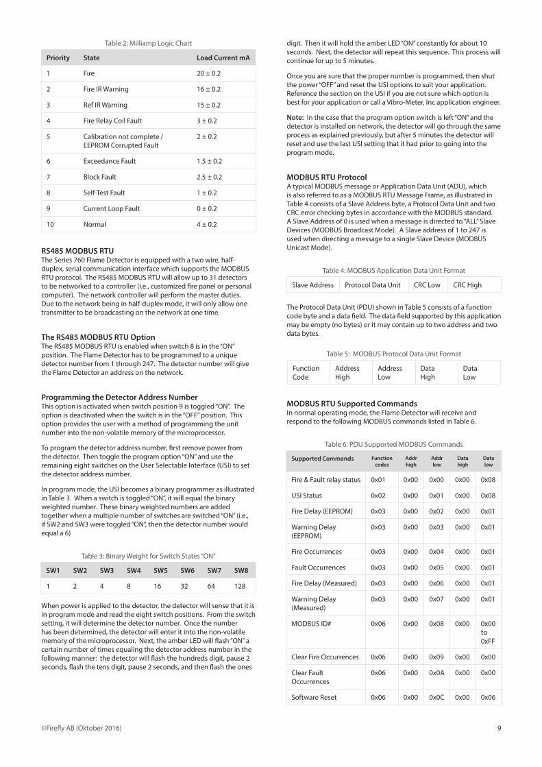
0 to 20 mA OutputSwitch position 7 selects the 0 to 20 mA output option . If this output is utilized, then switch position 7 must be “ON” . Otherwise, if this output is not used, switch position 7 must be kept “OFF” or it will cause the Fault Outputs to turn “ON” . Table 2 illustrates the order of priority .
9©Firefly AB (Oktober 2016)
Table 2: Milliamp Logic Chart
Priority State Load Current mA
1 Fire 20 ± 0 .2
2 Fire IR Warning 16 ± 0 .2
3 Ref IR Warning 15 ± 0 .2
4 Fire Relay Coil Fault 3 ± 0 .2
5 Calibration not complete / EEPROM Corrupted Fault
2 ± 0 .2
6 Exceedance Fault 1 .5 ± 0 .2
7 Block Fault 2 .5 ± 0 .2
8 Self-Test Fault 1 ± 0 .2
9 Current Loop Fault 0 ± 0 .2
10 Normal 4 ± 0 .2
RS485 MODBUS RTUThe Series 760 Flame Detector is equipped with a two wire, half-duplex, serial communication interface which supports the MODBUS RTU protocol . The RS485 MODBUS RTU will allow up to 31 detectors to be networked to a controller (i .e ., customized fire panel or personal computer) . The network controller will perform the master duties . Due to the network being in half-duplex mode, it will only allow one transmitter to be broadcasting on the network at one time .
The RS485 MODBUS RTU OptionThe RS485 MODBUS RTU is enabled when switch 8 is in the “ON” position . The Flame Detector has to be programmed to a unique detector number from 1 through 247 . The detector number will give the Flame Detector an address on the network .
Programming the Detector Address NumberThis option is activated when switch position 9 is toggled “ON” . The option is deactivated when the switch is in the “OFF” position . This option provides the user with a method of programming the unit number into the non-volatile memory of the microprocessor .
To program the detector address number, first remove power from the detector . Then toggle the program option “ON” and use the remaining eight switches on the User Selectable Interface (USI) to set the detector address number .
In program mode, the USI becomes a binary programmer as illustrated in Table 3 . When a switch is toggled “ON”, it will equal the binary weighted number . These binary weighted numbers are added together when a multiple number of switches are switched “ON” (i .e ., if SW2 and SW3 were toggled “ON”, then the detector number would equal a 6)
Table 3: Binary Weight for Switch States “ON”
SW1 SW2 SW3 SW4 SW5 SW6 SW7 SW8
1 2 4 8 16 32 64 128
When power is applied to the detector, the detector will sense that it is in program mode and read the eight switch positions . From the switch setting, it will determine the detector number . Once the number has been determined, the detector will enter it into the non-volatile memory of the microprocessor . Next, the amber LED will flash “ON” a certain number of times equaling the detector address number in the following manner: the detector will flash the hundreds digit, pause 2 seconds, flash the tens digit, pause 2 seconds, and then flash the ones
digit . Then it will hold the amber LED “ON” constantly for about 10 seconds . Next, the detector will repeat this sequence . This process will continue for up to 5 minutes .
Once you are sure that the proper number is programmed, then shut the power “OFF” and reset the USI options to suit your application . Reference the section on the USI if you are not sure which option is best for your application or call a Vibro-Meter, Inc application engineer .
Note: In the case that the program option switch is left “ON” and the detector is installed on network, the detector will go through the same process as explained previously, but after 5 minutes the detector will reset and use the last USI setting that it had prior to going into the program mode .
MODBUS RTU ProtocolA typical MODBUS message or Application Data Unit (ADU), which is also referred to as a MODBUS RTU Message Frame, as illustrated in Table 4 consists of a Slave Address byte, a Protocol Data Unit and two CRC error checking bytes in accordance with the MODBUS standard . A Slave Address of 0 is used when a message is directed to “ALL” Slave Devices (MODBUS Broadcast Mode) . A Slave address of 1 to 247 is used when directing a message to a single Slave Device (MODBUS Unicast Mode) .
Table 4: MODBUS Application Data Unit Format
Slave Address Protocol Data Unit CRC Low CRC High
The Protocol Data Unit (PDU) shown in Table 5 consists of a function code byte and a data field . The data field supported by this application may be empty (no bytes) or it may contain up to two address and two data bytes .
Table 5: MODBUS Protocol Data Unit Format
Function Code
Address High
Address Low
Data High
Data Low
MODBUS RTU Supported CommandsIn normal operating mode, the Flame Detector will receive and respond to the following MODBUS commands listed in Table 6 .
Table 6: PDU Supported MODBUS Commands
Supported Commands Function codes
Addr high
Addr low
Data high
Data low
Fire & Fault relay status 0x01 0x00 0x00 0x00 0x08
USI Status 0x02 0x00 0x01 0x00 0x08
Fire Delay (EEPROM) 0x03 0x00 0x02 0x00 0x01
Warning Delay (EEPROM)
0x03 0x00 0x03 0x00 0x01
Fire Occurrences 0x03 0x00 0x04 0x00 0x01
Fault Occurrences 0x03 0x00 0x05 0x00 0x01
Fire Delay (Measured) 0x03 0x00 0x06 0x00 0x01
Warning Delay (Measured)
0x03 0x00 0x07 0x00 0x01
MODBUS ID# 0x06 0x00 0x08 0x00 0x00 to 0xFF
Clear Fire Occurrences 0x06 0x00 0x09 0x00 0x00
Clear Fault Occurrences
0x06 0x00 0x0A 0x00 0x00
Software Reset 0x06 0x00 0x0C 0x00 0x06

10 ©Firefly AB (Oktober 2016)
MODBUS RTU ResponseBased on the commands from Table 6, the read functions from the Flame Detector are functions 1, 2, 3 and 7 . In response to these commands the Flame Detector will follow the PDU format illustrated in Table 7 . For function 6, the Flame Detector will simply echo the received PDU to acknowledge that the specified command was performed .
Note: The second PDU byte contains either the number of data bytes that follow or, in the case of the Exception Status Word, Variable Data as supplied by the main micro-controller .
Table 7: PDU Formats for Transmission of MODBUS Read Results
Read Command
Function Code
See Note
Variable Data
Variable Data
Fire & Fault relay status
0x 01 0x01 See Table 8
Not Used
USI Status 0x 02 0x01 See Table 9
Not Used
Fire Delay (EEPROM)
0x 03 0x02 See Table 10
See Table 11
Warning Delay (EEPROM)
0x 03 0x02 See Table 10
See Table 11
Fire Occurrences
0x 03 0x02 Hi Byte Lo Byte
Fault Occurrences
0x 03 0x02 Hi Byte Lo Byte
Fire Delay (Measured)
0x 03 0x02 See Table 10
See Table 11
Warning Delay (Measured)
0x03 0x02 See Table 10
See Table 11
Exception Status Word
0x 07 See Table 12
Not Used Not Used
As illustrated in Table 8, if the relay is energized, the corresponding bit will be set (1, high) . If the relay is de-energized, the corresponding bit will be cleared (0, low) .
Table 8: MODBUS Function 0x01 Read Coil Response
Bit 7:2 Bit 1 Bit 0
Always 0 (Cleared) Fault Relay Status Fire Relay Status
As depicted in Table 9, if the option is active, the corresponding bit will be set . If the option is not active, the corresponding bit will be cleared .
Table 9: USI Status Bit Definition
Bit 7 Bit 6 Bit 5 Bit 4 Bit 3:2 Bit 1 Bit 0
RS-485 ENQ
0 to 20 mA Output
Fire Output Latch-ing
War-ning Indica-tion
Sensiti-vity
Manual Test
Auto-matic Test
Table 10: Byte Definition for Delay Time Whole Number
Bit 7:4 Bit 3:0
BCD of 10’s digit BCD of 1’s digit
Table 11: Byte Definition for Delay Time Decimal
Bit 7:4 Bit 3:0
BCD of tenth’s digit Always cleared
Note: An example using Table 10 and 11; if the delay time is 25 .3 seconds, the two bytes transmitted would be 0x25 and 0x30 .
As shown in Table 12, the status word has seven alarm bits and one valid transmission bit . When bits 0 through 6 are at a logic zero, the alarms are “OFF” . When bits 0 through 6 are at a logic one, the alarms are “ON” . Bit 7 is always “ON” . If bits 4 through 7 are set to logic one then the relay coil is open . If bits 3 through 7 are set to logic one then the non-volatile memory has been corrupted .
If the bits 1, 3 through 7 are all set to a logic one then the fire channel is in exceedance due to saturation either from excessive heating or cooling . If bits 2, 3 through 7 are all set to a logic one, then the reference channel is in exceedance due to saturation either from excessive heating or cooling . If bits 1, 4 and 7 are all set to a logic one, then the fire window is being blocked or the sensor is producing an illogical signal level as compared to the reference channel . If bits 2, 5 through 7 are set to a logic one, then the reference channel window is being blocked or the sensor is producing an illogical signal level as compared to the fire channel .
Table 12: Status Word Definition
Bit 7 Bit 6 Bit 5 Bit 4 Bit 3 Bit 2 Bit 1 Bit 0
Always On
Manual Test Fault
Auto Test Ref IR Fault
Auto Test Fire IR Fault
Milli-amp Fault
Ref IR Warn-ing
Fire IR Warn-ing
Fire
MODBUS RTU Exception HandlingAn exception is an error detected by the Flame Detector . If an error should occur from the received command, the Flame Detector will respond with a PDU in the form of Table 13 .
Table 13: PDU Format for MODBUS Exception Reporting
Exception Function Code Exception Code
(0x80 + MODBUS Function Code) See Table 14
When assembling the PDU to annunciate an error, the Flame Detector will calculate an Exception Function Code equal to 0x80 plus the received MODBUS Function Code, i .e . if the MODBUS function was 0x03, the Exception Function Code is 0x83 . Table 14 contains the supported Exception Codes that will be returned depending on the type of error detected .
Table 14: Supported Exception Codes
Exception Exception Code
Reporting Priority
Illegal function requested 0x01 1
Illegal address specified 0x02 2
Illegal data specified 0x03 3
Fire Detector Request failure
0x04 4

11©Firefly AB (Oktober 2016)
Maintenance and troubleshootingNote: It is recommended that when cleaning or servicing the Flame Detector, that any suppression or alarm systems be disabled .
Omniguard® 760 Series Flame Detector is designed for years of trouble-free operation with minimal attention . Periodic cleaning of the optical surfaces is essential, however, for maintaining reliable fire protection . The frequency of required cleaning will be determined by the environmental conditions in and around the installation . The detectors should be regularly inspected for a build-up of dust or other contaminants on the optical surfaces .
The detection specifications presented in this manual are predicated on performance with clean sensor windows . Contaminants such as dust, oil and paint will reduce sensitivity . Severe contamination on the light guides or sensor windows will cause a failure of the self-test . A detector that fails self-test due to dirty optical surfaces may be capable of detecting fire, but its effectiveness will be limited to 30 to 50% of its specified range .
Cleaning Procedure:Locate the following optical surfaces: (Figure 9)
1 . Fire IR Window
2 . Fire Light Guide End
3 . Reference IR Window
4 . Reference Light Guide End
Clean the optical surfaces with a cotton swab wetted with commercial liquid glass cleaner, ammonia, methanol, or isopropyl alcohol . Rinse with clean water and dry with lens quality cloth . Repeat with methanol if needed to remove smudges .
Caution: Wiping with excessive force or inappropriate materials may scratch the optical surfaces and impair performance .
Troubleshooting:
*WARNING* Do not attempt to repair a detector . Study these troubleshooting guidelines and review the referenced sections of the manual prior to performing maintenance on the fire detection system .
New Installations:When the detectors are in operational mode, a green LED will be visible for one second approximately every ten seconds . If any or all the detectors fail to operate, check the system wiring and power supply . Tight, reliable wiring connections are essential, as are low-resistance connections from every detector housing to earth ground . Measure the voltage between terminals 8 and 10 at the detector locations to verify that the supply voltage is within range .
Note: Voltage at detectors installed farthest from power source will be lower than the no-load supply voltage due to line losses . Maximum load condition occurs during manual test .
The Omniguard® 760 Series Flame Detectors employ sensitive and sophisticated electronic circuitry . Power line transients or excessive power supply ripple may therefore cause erratic or intermittent operation . DC-powered detectors function best with ripple-free (less than 1 percent) supply voltage; power supply filtering may be necessary to improve performance . In areas that are unprotected from shielding and have the potential for conducted RFI/EMI directly into the power lines, it is highly recommended to use a Corcom Filter P/N 15DCB6F or equivalent on the power lines .
Note: For reliable operation, the instantaneous supply voltage at the input to any detector must not fall below 20 Vdc or exceed 30 Vdc .
Failure To Alarm:Upon detection of fire, the fire outputs will activate and the red LED, visible through the LED window, will turn “ON” .
If during testing a detector fails to alarm, inspect the sensor windows for cleanliness . Clean sensor windows are essential for effective optical fire detection . Clean all the optical surfaces per the cleaning procedures previously described and retest the detector .
Should the detector continue to be inoperative, check the supply voltage and all associated wiring . Incorrect power supply voltage or loose connections will cause marginal or intermittent performance .
Alarm Condition – No Fire Present:A detector in alarm condition when no fire is present may be caused by an inadvertent actuation of the manual test . The Series 760 Flame Detectors feature a manually initiated self-test feature of the optical and electronic systems . If the light guides are continuously illuminated, check the manual test wiring and the test switch for broken, loose, or intermittent connections . Repair or tighten any faulty connections . If the light guides are not illuminated, then contact your Firefly AB representative .
Confidence Condition:The Model 760 Flame Detectors are equipped with a fault relay to annunciate a change in the operational status of the detector . When power is applied to the detector, the fault relay will energize within 8 seconds under normal environmental conditions . A loss of power will cause the relay to de-energize .
If the fault relay output fails to change state within 8 seconds after power-up and the amber LED fails to illuminate, then there may be no power reaching the detector’s electronic module . Check the supply voltage, the condition of the fuse located at F1 on the PCB and the wiring to terminals 8 and 10 . Also, inspect the wiring to the fault relay terminals 6 and 7 and the jumper JP1 that sets the fault relay option .
Note: Model 760 Flame Detectors are equipped with a 0 to 20 mA option . A loss of power will result in a constant 0 mA output .
If the fault relay output continues to be inoperative, isolate the relay contacts by disconnecting the external wiring to the fault relay terminals . Connect an Ohmmeter across the fault relay terminals and monitor for an actuation of the relay . Repair the external wiring if necessary .
Fault Condition:Note: During environmental conditions that cause a large thermal transient such as moving a detector from inside a warm building to outside in the cold, the detector will be inoperable until it stabilizes to the new thermal condition . The fault relay will remain off and the Amber LED will flash at a 2 Hz rate due to the exceedance until the detector acclimates to the environment . This will be an indication of an Exceedance Fault .
Model 760 Flame Detectors are equipped with a 0 to 20 mA output . When the 0 to 20 mA option is not used, make sure that the 0 to 20 mA option is “OFF” on the USI . If the 0 to 20 mA option is “ON” and at any time the driveline opens or the current sense is not at the proper level, it will cause the activation of the fault outputs . Check the wire terminal 15 and insure that a good signal ground is present at terminal 10 or 11 . To insure that the 0 to 20 mA option causes the fault
(Fig 9) Optical Surfaces

12 ©Firefly AB (Oktober 2016)
condition, toggle the option on the USI “OFF” and reset the detector by toggling the power off then on . If the fault condition continues to be activated, then the problem is in a different section .
Note: If the Model 760 is placed near a grey body source with the equivalence of the object being at a minimum temperature of 150°F (65°C) from a distance of 22 in . [55 .9 cm] and if one of the IR sensor window is blocked while the other one remains unblocked then the Amber LED will flash at the rate of 4 Hz until the blockage is removed from the window’s viewing area . This will be an indication of a Block Fault
Model 760 Flame Detectors are equipped with automatic self-test in addition to the manual test . Approximately every 15 minutes the automatic self-test is actuated, and for a brief time interval, the optics and electronics are checked for functionality . A failure of the automatic self-test is annunciated by the activation of the Fault Outputs . If a detector goes into a fault condition, the optical surfaces should be checked for cleanliness . Clean sensor windows and light guide ends are necessary for the detector(s) to pass self-test .
After the optical surfaces have been inspected and cleaned, reset the detector . If the detector is wired for manual test, perform the manual test . The typical response time should be to approximately 0 .6 seconds beyond the actual fire output time delay .
*WARNING* During Manual Test, the fire outputs will be actuated . Always disable fire suppression and alarm systems before testing .
If the detector continues to go into a fault condition following a cleaning of the optical surfaces, check the supply voltage and wiring at terminals 8 or 9 and 10 or 11 . Look for loose or intermittent connections .
During normal operation, the fault outputs will change state on power-up . The output will return to its original state if power to the detector is removed . If the fault output is intermittent or erratic, check the supply voltage and wiring to terminals 8 or 9 and 10 or 11 . Inspect the fault relay wiring on the detectors . Repair or tighten any loose connections .
If the Warning option is “ON”, the fault relay will be flashing at a 1 Hz rate whenever a fault conditions exists .
Manual Test Failure:*WARNING* This will activate the fire outputs . Always disable extinguishing circuits before testing .
A manual test is activated by connecting the test circuit terminal 12 to the plus terminal of the detector’s input power supply (terminal 8 or 9) . During manual test, the optical and electronic systems of detector are checked . Upon successful completion of the test, the fire outputs will be activated . Also, the red LED inside the detector, visible through the LED window, will turn “ON” . The typical response time is 0 .6 seconds beyond the actual fire output time delay . If the detector fails to respond to a manual test, check to see if the USI manual test option is “ON” (switch position 1) .
If the detector fails manual test and activates the fault outputs or if the response time is longer than expected, the optical surfaces of the detector may require cleaning . Clean the sensor windows and light guide ends . After cleaning, initiate the manual test .
If the detector again fails manual test, check the wiring to the supply voltage terminals 8 or 9 and 10 or 11 . The detector may not be receiving enough power; the wiring connections may be loose or intermittent . If the red LED is illuminated and there is no fire output, then check all connections to the fire alarm panel or annunciating devices . A defective test switch may prevent the test circuit from initializing . Initiate the manual test by connecting a wire from the test switch terminals to the positive terminal of the input power supply . Replace the switch if the manual test operates when the wire is connected .
Warning:In addition to detecting fire, the Omniguard® 760 Series Flame Detector will annunciate a warning of potentially hazardous conditions that could cause a fire .
When the detector senses a persistent source of infrared radiation from heat sources the Warning Outputs will change state . To enable the Warning Outputs for the relay, the Warning option (switch position 5) must be “ON” . When the Warning Outputs are activated, it will cause the fault relay to be “OFF” and the amber LED to be “ON” constantly . If the 0 to 20 mA is “ON”, it will set the output to 16 mA for the Fire IR Warning and 15 mA for the Reference IR Warning . The Warning Outputs are non-latching and will change states if the problem source is removed .
This Warning alarm is used as a tool to help prevent unwanted Fire alarms . By identifying problem heat sources in the detector’s field-of-view and making appropriate changes, i .e . shielding or re-aiming of the detector, potential false fire alarms can be avoided . A Warning should always be investigated with caution . Inspect the protected area . If no radiation sources are apparent, cover the detector with opaque material to test whether the Warning disappears when the sensor windows are blocked . If the Warning does not disappear after blocking the windows, a sensor channel may be faulty and in need of repair .
RS485 User Interface (UI)If no communication has been established, check the wiring to be sure that the polarity is not reversed on the two wires . The network can be daisy chained, but it does require two 120Ω terminating resistors in order to minimize reflections . One resistor should be placed at the network controller or master device . The other resistor should be placed at the farthest location from the network controller or master device . RS485 allows up to 4000 feet or 24 AWG twisted-pair wire driving into 120Ω loads . Line polarization should be implemented at the network controller or master device .
Service and repairContact Firefly AB or your Firefly AB distributor for details on our customer support and repair services . Prior to returning defective material, please contact the Firefly AB service and repair department for additional procedural information .
Omniguard® 760 Series Flame Detectors are not field-serviceable and the flameproof joints are not intended to be repaired . . An unauthorized attempt to repair or re-calibrate a detector will void the warranty .
Detectors should be carefully packaged to avoid damage from shock, moisture and dust . When shipping detectors back to Firefly AB, use the original shipping carton, if available . If the original packing material is not available, wrap the detector in plastic and ample packing material to cushion the detector .
WarrantyThe warranty period is thirty-six (36) months for the Omniguard® 760 Series Flame Detectors and five (5) years for the IR Sensors . Firefly AB will, at its option, repair and return without charge (freight prepaid) any Omniguard® product, used in accordance with Firefly AB ratings and instructions and confirmed by Firefly AB to be defective in workmanship or materials . This warranty shall be valid only if the product is returned, within the applicable warranty period, to the factory at Stockholm, Sweden properly packed and with all transportation charges prepaid .
All warranty periods commence from the date the product is shipped to the end user, provided that delivery is within six (6) months of the date the product was originally shipped from the factory . There are no warranties of merchantability, fitness, or implied warranties of any kind, or representations for any other Firefly AB product, except the warranty specified herein . In no event shall Firefly AB be liable for any consequential, special, or other damages attributable to our product . The buyer is solely responsible for the proper installation, maintenance and use of the Omniguard® Flame Detectors, and agrees Firefly AB is not in any way liable for any special incidental or consequential damages whatsoever .

13©Firefly AB (Oktober 2016)
Ordering information
Fire type 0 Hydrocarbon/non-hydrocarbon 1 Hydrocarbon (only available with Approval 3) Housing material/conduit entry 0 Aluminium, 3/4-14 NPT (white) 2 Stainless Steel, 3/4-14 NPT 3 Aluminium, M20-1 .5 (white) 5 Stainless Steel, M20-1 .5 Test feature 1 Auto self-test
Type: Omniguard® model 760
Ordering number: 760 - X X X X X
Approval 0 FM, SIL2, CSA, Russian Fire Certificate, IECEx, ATEX, EMC, LVD, CSFM 3 SIL2, IECEx, ATEX, EMC, LVD Fire relay configuration 0 Latching 1 Non-Latching
Designation: Multi-spectrum infrared flame detector
To order, please specify

14 ©Firefly AB (Oktober 2016)
Notes

15©Firefly AB (Oktober 2016)

Firefly ABPhone: +46 (0)8 449 25 00Fax: +46 (0)8 449 25 01E-mail: omniguardsales@firefly .se www .omniguardbyfirefly .se
AddressHeliosgatan 3120 30 StockholmSwedenPublication No . 1031231 Rev . D