

750-183 OM Boilermate June10
51
Cleaver-Brooks Operation, Maintenance, and Parts Manual Spraymaster ® Deaerator Boilermate ® Deaerator Deaerator and Surge Controls $25.00 CB-750-183 Cleaver Brooks ® Performance Proven Worldwide
-
Upload
elio-santana-gonzenbach -
Category
Documents
-
view
58 -
download
4
Transcript of 750-183 OM Boilermate June10
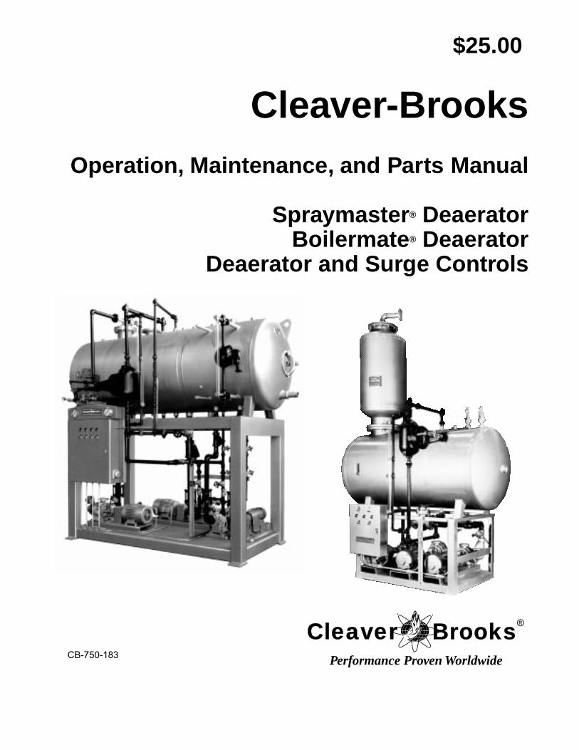
Cleaver-Brooks
Operation, Maintenance, and Parts Manual
Spraymaster
®
DeaeratorBoilermate
®
Deaerator Deaerator and Surge Controls
$25.00
CB-750-183
Cleaver Brooks®
Performance Proven Worldwide
TO:
Owners, Operators and/or Maintenance Personnel
This operating manual presents information that will help to properly operate and care for the equipment. Study its contents carefully. The unit will provide good service and continued operation if proper operating and maintenance instructions are fol-lowed. No attempt should be made to operate the unit until the principles of operation and all of the components are thoroughly understood.
It is the responsibility of the owner to train and advise not only his or her personnel, but the contractors' personnel who are ser-vicing, repairing, or operating the equipment, in all safety aspects.
Cleaver-Brooks equipment is designed and engineered to give long life and excellent service on the job. The electrical and me-chanical devices supplied as part of the unit were chosen because of their known ability to perform; however, proper operating techniques and maintenance procedures must be followed at all times.
Any "automatic" features included in the design do not relieve the attendant of any responsibility. Such features merely free him of certain repetitive chores and give him more time to devote to the proper upkeep of equipment.
It is solely the operator’s responsibility to properly operate and maintain the equipment. No amount of written instructions can replace intelligent thinking and reasoning and this manual is not intended to relieve the operating personnel of the responsibility for proper operation. On the other hand, a thorough understanding of this manual is required before attempting to operate, main-tain, service, or repair this equipment.
Operating controls will normally function for long periods of time and we have found that some operators become lax in their daily or monthly testing, assuming that normal operation will continue indefinitely. Malfunctions of controls lead to uneconom-ical operation and damage and, in most cases, these conditions can be traced directly to carelessness and deficiencies in testing and maintenance.
The operation of this equipment by the owner and his operating personnel must comply with all requirements or regulations of his insurance company and/or other authority having jurisdiction. In the event of any conflict or inconsistency between such requirements and the warnings or instructions contained herein, please contact Cleaver-Brooks before proceeding.
Cleaver-Brooks
Operation, Maintenance, and Parts ManualSpraymaster
®
DeaeratorBoilermate
®
Deaerator Deaerator and Surge Controls
Manual Part No. 750-1835/98
© Aqua-Chem, Inc., 1998
Please direct purchase orders for replacement manuals to your local Cleaver-Brooks authorized representative
Printed in U.S.A.

Notes
Table of Contents
Section 1 – Deaerators
1.1 GENERAL . . . . . . . . . . . . . . . . . . . . . . . . . . . . . . . . . . . . . . . . . . . . . . . . . . . . . . . . . . . . . . . . . 1-1 1.2 DESCRIPTION AND PRINCIPLES OF OPERATION . . . . . . . . . . . . . . . . . . . . . . . . . . . . . 1-2
1.2.2 Spraymaster Deaerator . . . . . . . . . . . . . . . . . . . . . . . . . . . . . . . . . . . . . . . . . . . . . . . . . . . 1-31.2.3 Boilermate Deaerator . . . . . . . . . . . . . . . . . . . . . . . . . . . . . . . . . . . . . . . . . . . . . . . . . . . . 1-3
1.3 SYSTEM LAY-OUT . . . . . . . . . . . . . . . . . . . . . . . . . . . . . . . . . . . . . . . . . . . . . . . . . . . . . . . . . 1-81.3.1 General . . . . . . . . . . . . . . . . . . . . . . . . . . . . . . . . . . . . . . . . . . . . . . . . . . . . . . . . . . . . . . . 1-81.3.2 Plan A . . . . . . . . . . . . . . . . . . . . . . . . . . . . . . . . . . . . . . . . . . . . . . . . . . . . . . . . . . . . . . . 1-81.3.3 Plan B . . . . . . . . . . . . . . . . . . . . . . . . . . . . . . . . . . . . . . . . . . . . . . . . . . . . . . . . . . . . . . . . 1-8
1.4 OPERATING INSTRUCTIONS . . . . . . . . . . . . . . . . . . . . . . . . . . . . . . . . . . . . . . . . . . . . . . . . 1-111.4.1 Installation 1-111.4.2 Water Pumps . . . . . . . . . . . . . . . . . . . . . . . . . . . . . . . . . . . . . . . . . . . . . . . . . . . . . . . . . . . 1-111.4.3 Flexible Coupling Alignment . . . . . . . . . . . . . . . . . . . . . . . . . . . . . . . . . . . . . . . . . . . . . . 1-121.4.4 Initial Startup . . . . . . . . . . . . . . . . . . . . . . . . . . . . . . . . . . . . . . . . . . . . . . . . . . . . . . . . . . 1-131.4.5 Operation and Adjustments . . . . . . . . . . . . . . . . . . . . . . . . . . . . . . . . . . . . . . . . . . . . . . . . 1-13
1.5 MAINTENANCE . . . . . . . . . . . . . . . . . . . . . . . . . . . . . . . . . . . . . . . . . . . . . . . . . . . . . . . . . . . 1-16
Section 2 – Pressure Reducing Valve
START-UP AND SETTING . . . . . . . . . . . . . . . . . . . . . . . . . . . . . . . . . . . . . . . . . . . . . . . . . . . . . . 2-1HYDROSTATIC TEST PROCEDURE . . . . . . . . . . . . . . . . . . . . . . . . . . . . . . . . . . . . . . . . . . . . . 2-1TROUBLE SHOOTING . . . . . . . . . . . . . . . . . . . . . . . . . . . . . . . . . . . . . . . . . . . . . . . . . . . . . . . . . 2-1
Failure to Open, or Sagging Delivery Pressure . . . . . . . . . . . . . . . . . . . . . . . . . . . . . . . . . . . . . 2-1Failure to Close, or Over-Riding Delivery Pressure . . . . . . . . . . . . . . . . . . . . . . . . . . . . . . . . . 2-1
MAINTENANCE . . . . . . . . . . . . . . . . . . . . . . . . . . . . . . . . . . . . . . . . . . . . . . . . . . . . . . . . . . . . . . 2-2Inspection . . . . . . . . . . . . . . . . . . . . . . . . . . . . . . . . . . . . . . . . . . . . . . . . . . . . . . . . . . . . . . . . . . 2-2Dismantling Main Valve . . . . . . . . . . . . . . . . . . . . . . . . . . . . . . . . . . . . . . . . . . . . . . . . . . . . . . 2-2Replacing Seat Rings . . . . . . . . . . . . . . . . . . . . . . . . . . . . . . . . . . . . . . . . . . . . . . . . . . . . . . . . . 2-2Grinding In . . . . . . . . . . . . . . . . . . . . . . . . . . . . . . . . . . . . . . . . . . . . . . . . . . . . . . . . . . . . . . . . 2-2Valve Setting . . . . . . . . . . . . . . . . . . . . . . . . . . . . . . . . . . . . . . . . . . . . . . . . . . . . . . . . . . . . . . . 2-2
SPACE CONSIDERATIONS FOR REDUCING STATIONS . . . . . . . . . . . . . . . . . . . . . . . . . . . . 2-2PRESSURE REDUCING STATIONS GENERAL SPECIFICATIONS . . . . . . . . . . . . . . . . . . . . 2-2PLANNING THE INSTALLATION . . . . . . . . . . . . . . . . . . . . . . . . . . . . . . . . . . . . . . . . . . . . . . . 2-4IF IS NOISE A FACTOR . . . . . . . . . . . . . . . . . . . . . . . . . . . . . . . . . . . . . . . . . . . . . . . . . . . . . . . . 2-4
Section 3- Parts

Notes
54
1
13
9
2
7
8
39
36
38
26
27
43
41
40
3
42
35
29
33
30
31
32
22
24 25
2321
14
18
19 2017
16
15
12
11
6
10
28
H20
37
34
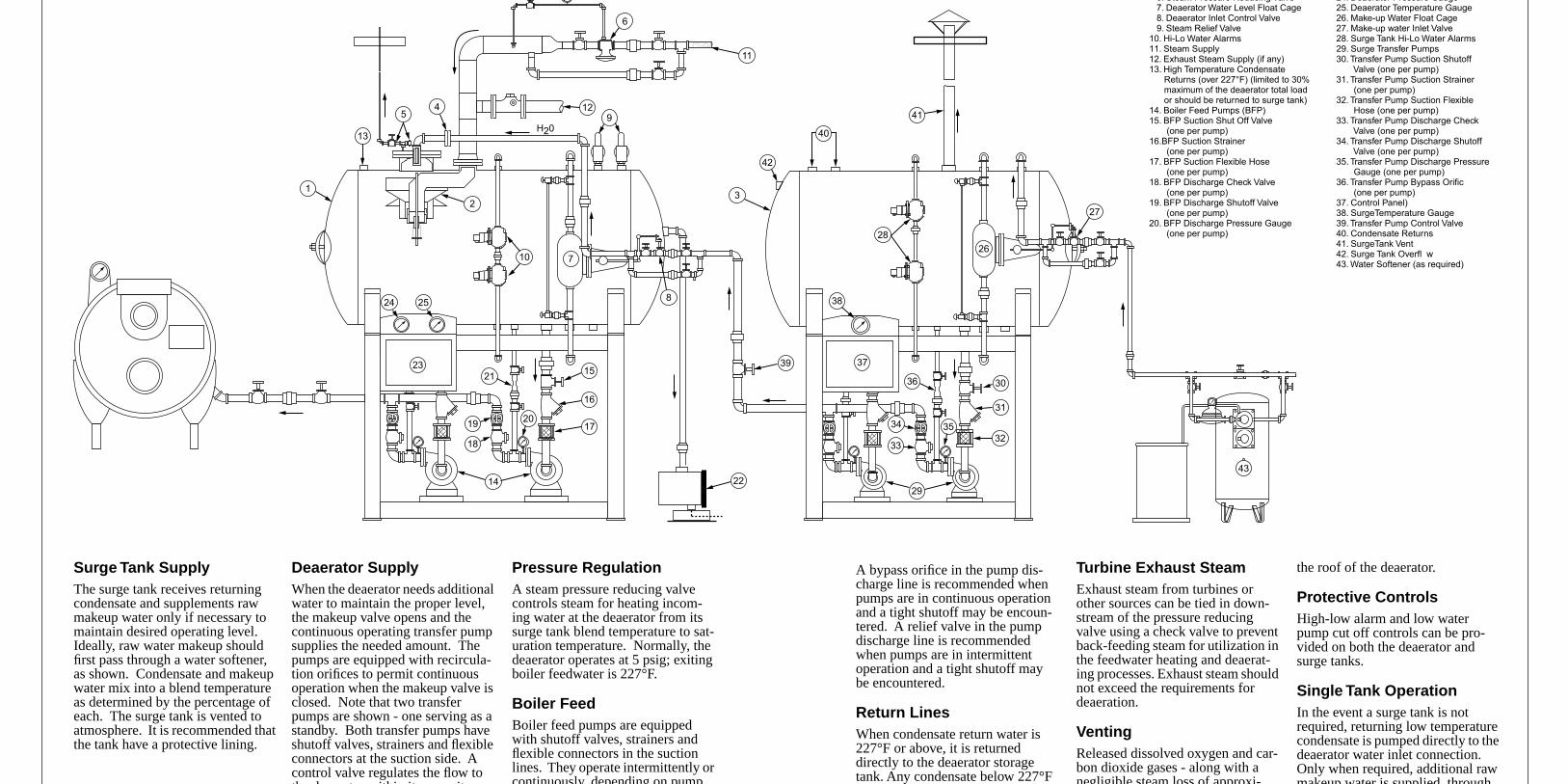
Surge Tank Supply
The surge tank receives returning condensate and supplements raw makeup water only if necessary to maintain desired operating level. Ideally, raw water makeup should first pass through a water softener, as shown. Condensate and makeup water mix into a blend temperature as determined by the percentage of each. The surge tank is vented to atmosphere. It is recommended that the tank have a protective lining.
Deaerator Supply
When the deaerator needs additional water to maintain the proper level, the makeup valve opens and the continuous operating transfer pump supplies the needed amount. The pumps are equipped with recircula-tion orifices to permit continuous operation when the makeup valve is closed. Note that two transfer pumps are shown - one serving as a standby. Both transfer pumps have shutoff valves, strainers and flexible connectors at the suction side. A control valve regulates the flow to th d t ithi it it
Pressure Regulation
A steam pressure reducing valve controls steam for heating incom-ing water at the deaerator from its surge tank blend temperature to sat-uration temperature. Normally, the deaerator operates at 5 psig; exiting boiler feedwater is 227°F.
Boiler Feed
Boiler feed pumps are equipped with shutoff valves, strainers and flexible connectors in the suction lines. They operate intermittently or continuously depending on pump
A bypass orifice in the pump dis-charge line is recommended when pumps are in continuous operation and a tight shutoff may be encoun-tered. A relief valve in the pump discharge line is recommended when pumps are in intermittent operation and a tight shutoff may be encountered.
Return Lines
When condensate return water is 227°F or above, it is returned directly to the deaerator storage tank. Any condensate below 227°F
Turbine Exhaust Steam
Exhaust steam from turbines or other sources can be tied in down-stream of the pressure reducing valve using a check valve to prevent back-feeding steam for utilization in the feedwater heating and deaerat-ing processes. Exhaust steam should not exceed the requirements for deaeration.
Venting
Released dissolved oxygen and car-bon dioxide gases - along with a negligible steam loss of approxi-
the roof of the deaerator.
Protective Controls
High-low alarm and low water pump cut off controls can be pro-vided on both the deaerator and surge tanks.
Single Tank Operation
In the event a surge tank is not required, returning low temperature condensate is pumped directly to the deaerator water inlet connection. Only when required, additional raw makeup water is supplied through
6. Steam Pressure Reducing Valve 7. Deaerator Water Level Float Cage 8. Deaerator Inlet Control Valve 9. Steam Relief Valve10. Hi-Lo Water Alarms11. Steam Supply12. Exhaust Steam Supply (if any)13. High Temperature Condensate Returns (over 227°F) (limited to 30% maximum of the deaerator total load or should be returned to surge tank)14. Boiler Feed Pumps (BFP)15. BFP Suction Shut Off Valve (one per pump)16.BFP Suction Strainer (one per pump)17. BFP Suction Flexible Hose (one per pump)18. BFP Discharge Check Valve (one per pump)19. BFP Discharge Shutoff Valve (one per pump)20. BFP Discharge Pressure Gauge (one per pump)
24. Deaerator Pressure Gauge25. Deaerator Temperature Gauge26. Make-up Water Float Cage27. Make-up water Inlet Valve28. Surge Tank Hi-Lo Water Alarms29. Surge Transfer Pumps30. Transfer Pump Suction Shutoff Valve (one per pump)31. Transfer Pump Suction Strainer (one per pump)32. Transfer Pump Suction Flexible Hose (one per pump)33. Transfer Pump Discharge Check Valve (one per pump)34. Transfer Pump Discharge Shutoff Valve (one per pump)35. Transfer Pump Discharge Pressure Gauge (one per pump)36. Transfer Pump Bypass Orific (one per pump)37. Control Panel)38. SurgeTemperature Gauge39. Transfer Pump Control Valve40. Condensate Returns41. SurgeTank Vent42. Surge Tank Overfl w43. Water Softener (as required)
750-183 1-1
Section 1
Deaerators
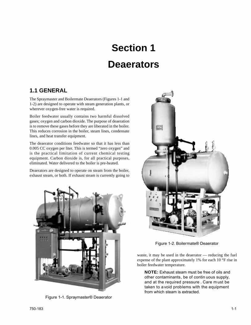
1.1 GENERAL
The Spraymaster and Boilermate Deaerators (Figures 1-1 and1-2) are designed to operate with steam generation plants, orwherever oxygen-free water is required.
Boiler feedwater usually contains two harmful dissolvedgases; oxygen and carbon dioxide. The purpose of deaerationis to remove these gases before they are liberated in the boiler.This reduces corrosion in the boiler, steam lines, condensatelines, and heat transfer equipment.
The deaerator conditions feedwater so that it has less than0.005 CC oxygen per liter. This is termed “zero oxygen” andis the practical limitation of current chemical testingequipment. Carbon dioxide is, for all practical purposes,eliminated. Water delivered to the boiler is pre-heated.
Deaerators are designed to operate on steam from the boiler,exhaust steam, or both. If exhaust steam is currently going to
waste, it may be used in the deaerator — reducing the fuelexpense of the plant approximately 1% for each 10 °F rise inboiler feedwater temperature.
NOTE:
Exhaust steam must be free of oils andother contaminants, be of contin uous supply,and at the required pressure . Care m ust betaken to a void problems with the equipmentfrom which steam is extracted.
Figure 1-1. Spraymaster® Deaerator
Figure 1-2. Boilermate® Deaerator
Deaerators
1-2 750-183
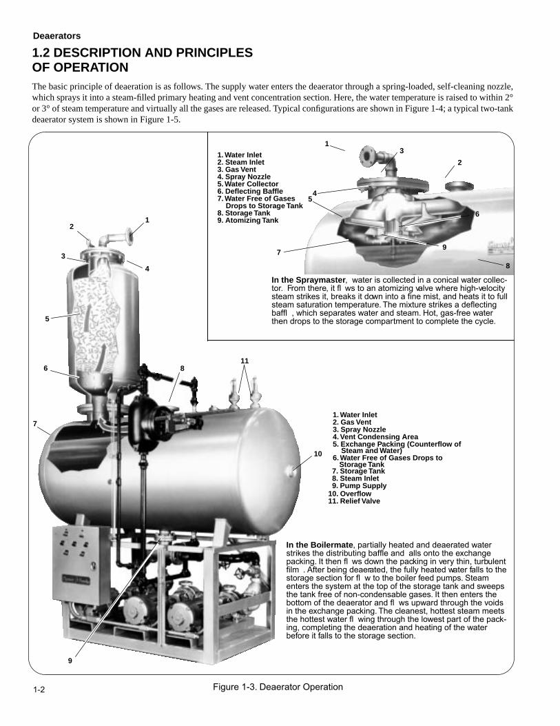
1.2 DESCRIPTION AND PRINCIPLESOF OPERATION
The basic principle of deaeration is as follows. The supply water enters the deaerator through a spring-loaded, self-cleaning nozzle,which sprays it into a steam-filled primary heating and vent concentration section. Here, the water temperature is raised to within 2°or 3° of steam temperature and virtually all the gases are released. Typical configurations are shown in Figure 1-4; a typical two-tankdeaerator system is shown in Figure 1-5.
In the Boilermate
, partially heated and deaerated water strikes the distributing baffle and alls onto the exchange packing. It then fl ws down the packing in very thin, turbulent film . After being deaerated, the fully heated water falls to the storage section for fl w to the boiler feed pumps. Steam enters the system at the top of the storage tank and sweeps the tank free of non-condensable gases. It then enters the bottom of the deaerator and fl ws upward through the voids in the exchange packing. The cleanest, hottest steam meets the hottest water fl wing through the lowest part of the pack-ing, completing the deaeration and heating of the water before it falls to the storage section.
In the Spraymaster
, water is collected in a conical water collec-tor. From there, it fl ws to an atomizing valve where high-velocity steam strikes it, breaks it down into a fine mist, and heats it to fullsteam saturation temperature. The mixture strikes a deflectingbaffl , which separates water and steam. Hot, gas-free water then drops to the storage compartment to complete the cycle.
Figure 1-3. Deaerator Operation
1
2
3
45
6
7
8
9
1. Water Inlet2. Steam Inlet3. Gas Vent4. Spray Nozzle5. Water Collector6. Deflecting Baffle7. Water Free of Gases
8. Storage Tank9. Atomizing Tank
Drops to Storage Tank
12
3
4
5
6
7
8
9
11
10
1. Water Inlet2. Gas Vent3. Spray Nozzle4. Vent Condensing Area5. Exchange Packing (Counterflow of
6. Water Free of Gases Drops to
7. Storage Tank8. Steam Inlet9. Pump Supply
10. Overflow11. Relief Valve
Steam and Water)
Storage Tank
Deaerators
750-183 1-3
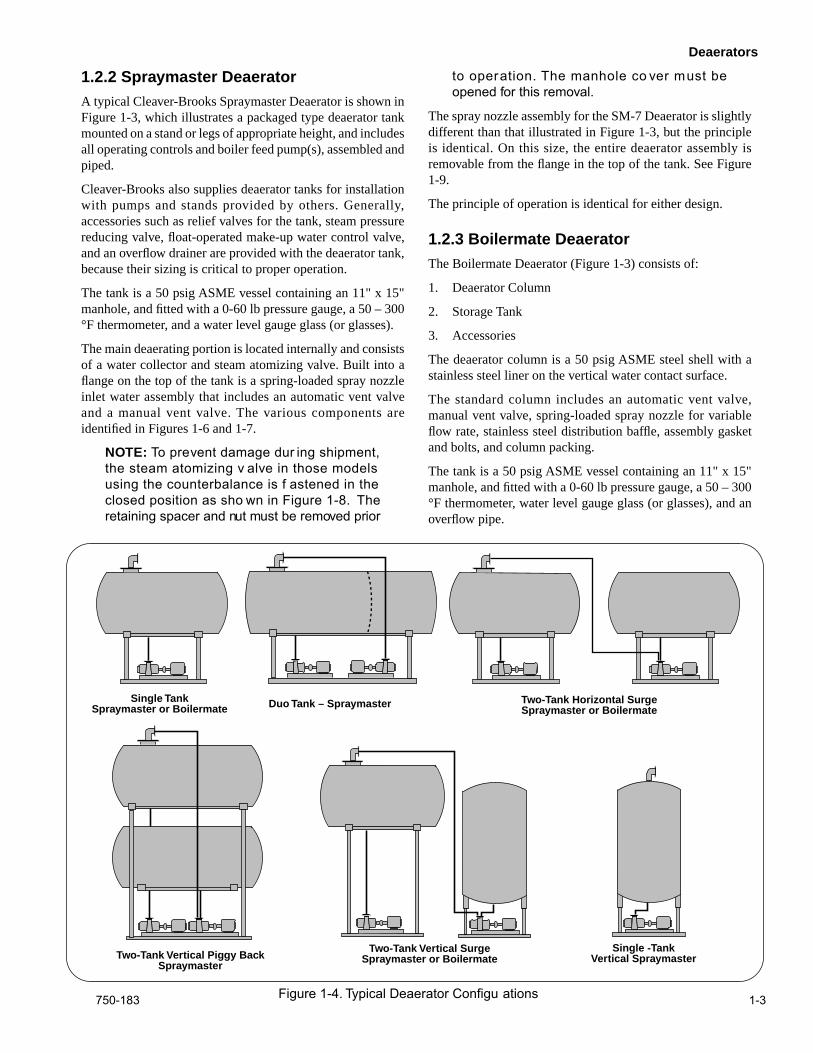
1.2.2 Spraymaster Deaerator
A typical Cleaver-Brooks Spraymaster Deaerator is shown inFigure 1-3, which illustrates a packaged type deaerator tankmounted on a stand or legs of appropriate height, and includesall operating controls and boiler feed pump(s), assembled andpiped.
Cleaver-Brooks also supplies deaerator tanks for installationwith pumps and stands provided by others. Generally,accessories such as relief valves for the tank, steam pressurereducing valve, float-operated make-up water control valve,and an overflow drainer are provided with the deaerator tank,because their sizing is critical to proper operation.
The tank is a 50 psig ASME vessel containing an 11" x 15"manhole, and fitted with a 0-60 lb pressure gauge, a 50 – 300°F thermometer, and a water level gauge glass (or glasses).
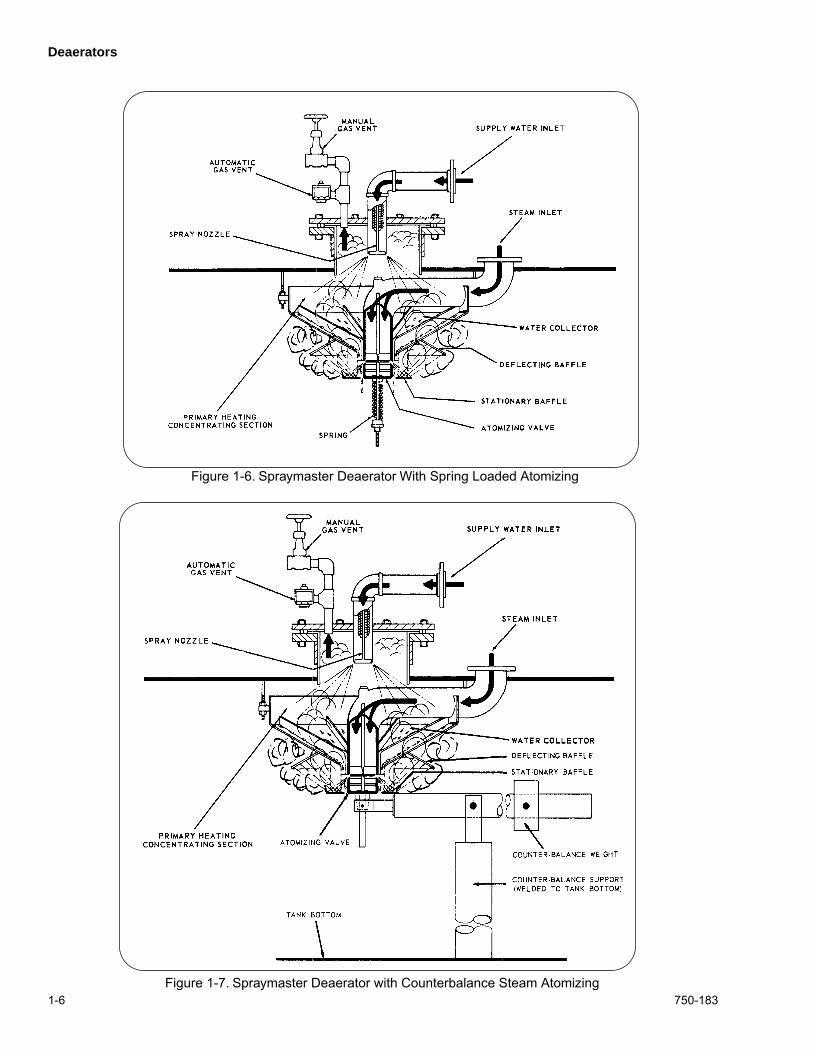
The main deaerating portion is located internally and consistsof a water collector and steam atomizing valve. Built into aflange on the top of the tank is a spring-loaded spray nozzleinlet water assembly that includes an automatic vent valveand a manual vent valve. The various components areidentified in Figures 1-6 and 1-7.
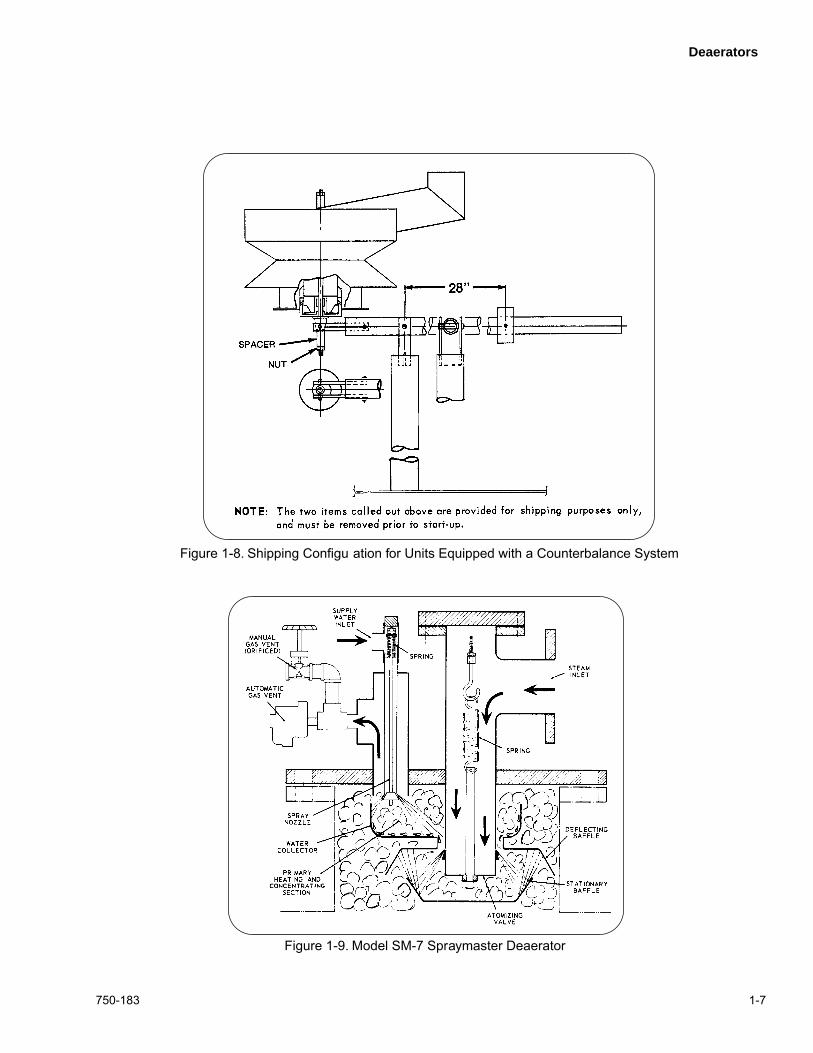
NOTE:
To prevent damage dur ing shipment,the steam atomizing v alve in those modelsusing the counterbalance is f astened in theclosed position as sho wn in Figure 1-8. Theretaining spacer and nut must be removed prior
to operation. The manhole co ver must beopened for this removal.
The spray nozzle assembly for the SM-7 Deaerator is slightlydifferent than that illustrated in Figure 1-3, but the principleis identical. On this size, the entire deaerator assembly isremovable from the flange in the top of the tank. See Figure1-9.
The principle of operation is identical for either design.
1.2.3 Boilermate Deaerator
The Boilermate Deaerator (Figure 1-3) consists of:
1. Deaerator Column
2. Storage Tank
3. Accessories
The deaerator column is a 50 psig ASME steel shell with astainless steel liner on the vertical water contact surface.
The standard column includes an automatic vent valve,manual vent valve, spring-loaded spray nozzle for variableflow rate, stainless steel distribution baffle, assembly gasketand bolts, and column packing.
The tank is a 50 psig ASME vessel containing an 11" x 15"manhole, and fitted with a 0-60 lb pressure gauge, a 50 – 300°F thermometer, water level gauge glass (or glasses), and anoverflow pipe.
Single TankSpraymaster or Boilermate Duo Tank – Spraymaster Two-Tank Horizontal Surge
Spraymaster or Boilermate
Two-Tank Vertical Piggy BackSpraymaster
Two-Tank Vertical SurgeSpraymaster or Boilermate
Figure 1-4. Typical Deaerator Configu ations
Single -TankVertical Spraymaster

Deaerators
1-4 750-183

Deaerators
750-183 1-5
Deaerators
1-6 750-183
Figure 1-7. Spraymaster Deaerator with Counterbalance Steam Atomizing
Figure 1-6. Spraymaster Deaerator With Spring Loaded Atomizing
Deaerators
750-183 1-7
Figure 1-8. Shipping Configu ation for Units Equipped with a Counterbalance System
Figure 1-9. Model SM-7 Spraymaster Deaerator
Deaerators
1-8 750-183
Accessories generally provided with the assembly are reliefvalve(s) for the tank, overflow drainer, steam pressurereducing valve, and float-operated make-up water controlvalve.
1.3 SYSTEM LAY-OUT
1.3.1 General
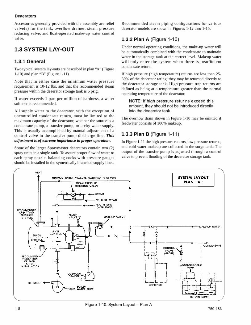
Two typical system lay-outs are described in plan “A” (Figure1-10) and plan “B” (Figure 1-11).
Note that in either case the minimum water pressurerequirement is 10-12 lbs, and that the recommended steampressure within the deaerator storage tank is 5 psig.
If water exceeds 1 part per million of hardness, a watersoftener is recommended.
All supply water to the deaerator, with the exception ofuncontrolled condensate return, must be limited to themaximum capacity of the deaerator, whether the source is acondensate pump, a transfer pump, or a city water supply.This is usually accomplished by manual adjustment of acontrol valve in the transfer pump discharge line.
Thisadjustment is of extreme importance to proper operation
.
Some of the larger Spraymaster deaerators contain two (2)spray units in a single tank. To assure proper flow of water toeach spray nozzle, balancing cocks with pressure gaugesshould be installed in the symetrically branched supply lines.
Recommended steam piping configurations for variousdeaerator models are shown in Figures 1-12 thru 1-15.
1.3.2 Plan A
(Figure 1-10)
Under normal operating conditions, the make-up water willbe automatically combined with the condensate to maintainwater in the storage tank at the correct level. Makeup waterwill only enter the system when there is insufficientcondensate return.
If high pressure (high temperature) returns are less than 25-30% of the deaerator rating, they may be returned directly tothe deaerator storage tank. High pressure trap returns aredefined as being at a temperature greater than the normaloperating temperature of the deaerator.
NOTE:
If high pressure retur ns exceed thisamount, they should not be introduced directlyinto the deaerator tank.
The overflow drain shown in Figure 1-10 may be omitted iffeedwater consists of 100% makeup.
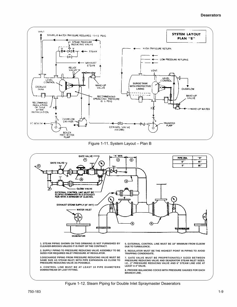
1.3.3 Plan B
(Figure 1-11)
In Figure 1-11 the high pressure returns, low pressure returns,and cold water makeup are collected in the surge tank. Theoutput of the transfer pump is adjusted through a controlvalve to prevent flooding of the deaerator storage tank.
Figure 1-10. System Layout – Plan A
Deaerators
750-183 1-9
Figure 1-11. System Layout – Plan B
Figure 1-12. Steam Piping for Double Inlet Spraymaster Deaerators
SURGE TANKWITH PROTECTIVE
LINING
1. STEAM PIPING SHOWN ON THIS DRWAING IS NOT FURNISHED BYCLEAVER-BROOKS UNLESS IT IS PART OF THE CONTRACT.
2. SUPPLY PIPING TO PRESSURE REDUCING VALVE ASSEMBLY TO BESIZED FOR REQUIRED INLET PRESSURE AT REGULATOR.
3.DISCHARGE PIPING FROM PRESSURE REDUCING VALVE MUST BESAME SIZE AS STEAM INLET, WITH PIPE EXPANSION AS CLOSE TOPRESSURE REDUCING VALVE AS POSSIBLE.
4. CONTROL LINE MUST BE AT LEAST 10 PIPE DIAMETERSDOWNSTREAM OF LAST FITTING.
5. EXTERNAL CONTROL LINE MUST BE 18” MINIMUM FROM ELBOWDUE TO TURBULENCE.
6. REGULATOR MUST BE THE HIGHEST POINT IN PIPING TO AVOIDTRAPPING CONDENSATE.
7. GATE VALVE MUST BE PROPRTIONATELY SIZED BETWEENPRESSURE REDUCING VALVE AND DEAERATOR STEAM INLET SIZES;I.E., 2” PRESSURE REDUCING VALVE AND 6” STEAM LINE USE ATLEAST A 4” VALVE.
8. PROVIDE BALANCING COCKS WITH PRESSURE GAUGES FOR EACHBRANCH LINE.
Deaerators
1-10 750-183
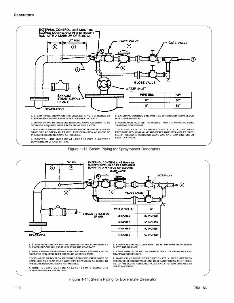
Figure 1-13. Steam Piping for Spraymaster Deaerators
1. STEAM PIPING SHOWN ON THIS DRWAING IS NOT FURNISHED BYCLEAVER-BROOKS UNLESS IT IS PART OF THE CONTRACT.
2. SUPPLY PIPING TO PRESSURE REDUCING VALVE ASSEMBLY TO BESIZED FOR REQUIRED INLET PRESSURE AT REGULATOR.
3.DISCHARGE PIPING FROM PRESSURE REDUCING VALVE MUST BESAME SIZE AS STEAM INLET, WITH PIPE EXPANSION AS CLOSE TOPRESSURE REDUCING VALVE AS POSSIBLE.
4. CONTROL LINE MUST BE AT LEAST 10 PIPE DIAMETERSDOWNSTREAM OF LAST FITTING.
5. EXTERNAL CONTROL LINE MUST BE 18” MINIMUM FROM ELBOWDUE TO TURBULENCE.
6. REGULATOR MUST BE THE HIGHEST POINT IN PIPING TO AVOIDTRAPPING CONDENSATE.
7. GATE VALVE MUST BE PROPRTIONATELY SIZED BETWEENPRESSURE REDUCING VALVE AND DEAERATOR STEAM INLET SIZES;I.E., 2” PRESSURE REDUCING VALVE AND 6” STEAM LINE USE ATLEAST A 4” VALVE.
Figure 1-14. Steam Piping for Boilermate Deaerator
1. STEAM PIPING SHOWN ON THIS DRWAING IS NOT FURNISHED BYCLEAVER-BROOKS UNLESS IT IS PART OF THE CONTRACT.
2. SUPPLY PIPING TO PRESSURE REDUCING VALVE ASSEMBLY TO BESIZED FOR REQUIRED INLET PRESSURE AT REGULATOR.
3.DISCHARGE PIPING FROM PRESSURE REDUCING VALVE MUST BESAME SIZE AS STEAM INLET, WITH PIPE EXPANSION AS CLOSE TOPRESSURE REDUCING VALVE AS POSSIBLE.
4. CONTROL LINE MUST BE AT LEAST 10 PIPE DIAMETERSDOWNSTREAM OF LAST FITTING.
5. EXTERNAL CONTROL LINE MUST BE 18” MINIMUM FROM ELBOWDUE TO TURBULENCE.
6. REGULATOR MUST BE THE HIGHEST POINT IN PIPING TO AVOIDTRAPPING CONDENSATE.
7. GATE VALVE MUST BE PROPRTIONATELY SIZED BETWEENPRESSURE REDUCING VALVE AND DEAERATOR STEAM INLET SIZES;I.E., 2” PRESSURE REDUCING VALVE AND 6” STEAM LINE USE ATLEAST A 4” VALVE.
Deaerators
750-183 1-11
1.4 OPERATING INSTRUCTIONS
1.4.1 Installation
This manual contains information on typical accessoryequipment such as water controls and steam reducing valves.Some installations may use specialized controls not coveredin this manual. In such cases, refer to the Manufacturer’sliterature. Familiarize yourself with the instructions for theparticular items furnished.
Installation should conform to the manufacturer’s printssupplied for the system. Check all piping for properconnections. Check all valves and controls to be sure they areinstalled with proper direction of flow.
Refer to Figures at the end of this section for appropriatepiping arrangements of controls.
IMPORTANT:
The steam pressure reducingvalve should be installed as near as practical tothe deaerator tank. Installation should be madein accordance with instr uctions of the v alvemanufacturer. The downstream piping MUSTbe the same size as the tapping in the tank. Theexternal control line MUST be installed to agreewith the man ufacturer’s recommendation.These recommendations will ensure the correctvolume of steam supplied to the deaerator.
The manual vent valve supplied with the deaerator has anorifice of a predetermined size drilled in its gate; since it isused for continuous venting, the discharge should be piped toatmosphere with no obstructions or resistance. The piping
must at least be the same size as the valve. See Table 1-1 forvalve and orifice sizes.
! DANGERCAUTION
Do not substitute or replace the man ual ventvalve. If there is any doubt, verify that the valvehas a dr illed gate pr ior to placing the unit intooperation.
The automatic vent valve may be piped to the outside,although it does not necessarily have to be. This valveprovides a faster means of venting at startup, or should therebe a sudden build up of gases.
NOTE: In the Boiler mate Deaerator, thepacking (stainless steel r ings) should becarefully dumped onto the suppor t grid, beingcareful to prevent damaging the grid. Be sure toachieve a unif orm distr ibution to maximiz eefficiency and thoroughness of deae ation.
! DANGERCAUTION
Wear suitable gloves when handling the rings toprevent cuts from sharp edges.
1.4.2 Water Pumps
If a “packaged” type system was provided, the height of thedeaerator storage tank above the boiler feed pumps will havebeen predetermined to obtain proper NPSH (Net PumpSuction Head); this height must be adhered to.
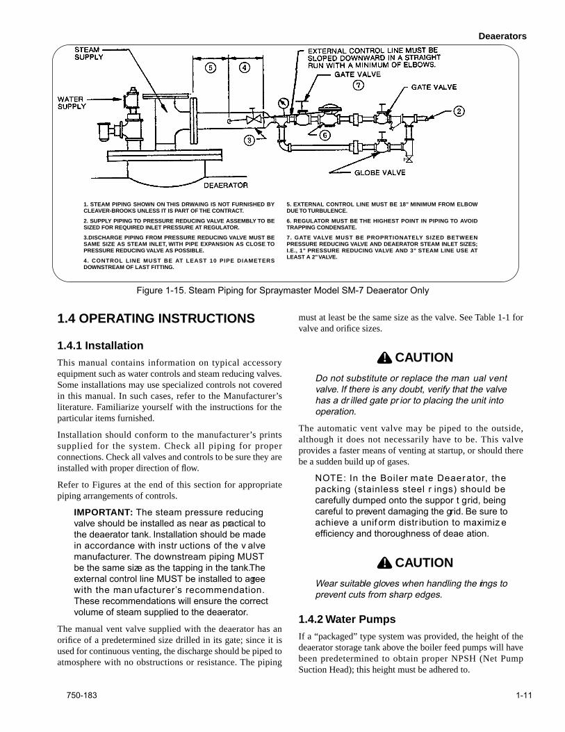
Figure 1-15. Steam Piping for Spraymaster Model SM-7 Deaerator Only
1. STEAM PIPING SHOWN ON THIS DRWAING IS NOT FURNISHED BYCLEAVER-BROOKS UNLESS IT IS PART OF THE CONTRACT.
2. SUPPLY PIPING TO PRESSURE REDUCING VALVE ASSEMBLY TO BESIZED FOR REQUIRED INLET PRESSURE AT REGULATOR.
3.DISCHARGE PIPING FROM PRESSURE REDUCING VALVE MUST BESAME SIZE AS STEAM INLET, WITH PIPE EXPANSION AS CLOSE TOPRESSURE REDUCING VALVE AS POSSIBLE.
4. CONTROL LINE MUST BE AT LEAST 10 PIPE DIAMETERSDOWNSTREAM OF LAST FITTING.
5. EXTERNAL CONTROL LINE MUST BE 18” MINIMUM FROM ELBOWDUE TO TURBULENCE.
6. REGULATOR MUST BE THE HIGHEST POINT IN PIPING TO AVOIDTRAPPING CONDENSATE.
7. GATE VALVE MUST BE PROPRTIONATELY SIZED BETWEENPRESSURE REDUCING VALVE AND DEAERATOR STEAM INLET SIZES;I.E., 1” PRESSURE REDUCING VALVE AND 3” STEAM LINE USE ATLEAST A 2” VALVE.
Deaerators
1-12 750-183
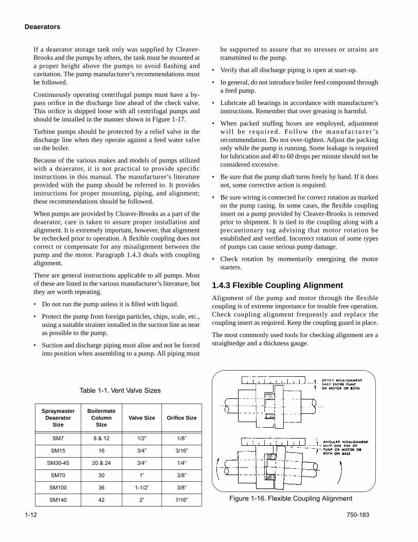
Table 1-1. Vent Valve Sizes
Spraymaster Deaerator
Size
Boilermate Column
SIzeValve Size Orifice Size
SM7 8 & 12 1/2” 1/8”
SM15 16 3/4” 3/16”
SM30-45 20 & 24 3/4” 1/4”
SM70 30 1” 3/8”
SM100 36 1-1/2” 3/8”
SM140 42 2” 7/16”
If a deaerator storage tank only was supplied by Cleaver-Brooks and the pumps by others, the tank must be mounted ata proper height above the pumps to avoid flashing andcavitation. The pump manufacturer’s recommendations mustbe followed.
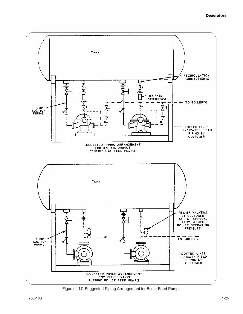
Continuously operating centrifugal pumps must have a by-pass orifice in the discharge line ahead of the check valve.This orifice is shipped loose with all centrifugal pumps andshould be installed in the manner shown in Figure 1-17.
Turbine pumps should be protected by a relief valve in thedischarge line when they operate against a feed water valveon the boiler.
Because of the various makes and models of pumps utilizedwith a deaerator, it is not practical to provide specificinstructions in this manual. The manufacturer’s literatureprovided with the pump should be referred to. It providesinstructions for proper mounting, piping, and alignment;these recommendations should be followed.
When pumps are provided by Cleaver-Brooks as a part of thedeaerator, care is taken to assure proper installation andalignment. It is extremely important, however, that alignmentbe rechecked prior to operation. A flexible coupling does notcorrect or compensate for any misalignment between thepump and the motor. Paragraph 1.4.3 deals with couplingalignment.
There are general instructions applicable to all pumps. Mostof these are listed in the various manufacturer’s literature, butthey are worth repeating.
• Do not run the pump unless it is filled with liquid.
• Protect the pump from foreign particles, chips, scale, etc.,using a suitable strainer installed in the suction line as nearas possible to the pump.
• Suction and discharge piping must aline and not be forcedinto position when assembling to a pump. All piping must
be supported to assure that no stresses or strains aretransmitted to the pump.
• Verify that all discharge piping is open at start-up.
• In general, do not introduce boiler feed compound througha feed pump.
• Lubricate all bearings in accordance with manufacturer’sinstructions. Remember that over greasing is harmful.
• When packed stuffing boxes are employed, adjustmentw i l l be requ i red . Fo l low the manufac tu re r ’srecommendation. Do not over-tighten. Adjust the packingonly while the pump is running. Some leakage is requiredfor lubrication and 40 to 60 drops per minute should not beconsidered excessive.
• Be sure that the pump shaft turns freely by hand. If it doesnot, some corrective action is required.
• Be sure wiring is connected for correct rotation as markedon the pump casing. In some cases, the flexible couplinginsert on a pump provided by Cleaver-Brooks is removedprior to shipment. It is tied to the coupling along with aprecautionary tag advising that motor rotation beestablished and verified. Incorrect rotation of some typesof pumps can cause serious pump damage.
• Check rotation by momentarily energizing the motorstarters.
1.4.3 Flexible Coupling Alignment
Alignment of the pump and motor through the flexiblecoupling is of extreme importance for trouble free operation.Check coupling alignment frequently and replace thecoupling insert as required. Keep the coupling guard in place.
The most commonly used tools for checking alignment are astraightedge and a thickness gauge.
Figure 1-16. Flexible Coupling Alignment
Deaerators
750-183 1-13
The coupling must be checked for both parallel (offset)a l ignment and angular (gap) a l ignment . Paral le lmisalignment occurs when shaft axes are parallel but notconcentric (see Figure 1-16). Angular misalignment is thereverse situation - shaft axes concentric but not parallel.
Align the coupling following instruction sheets provided withthe pump. If instructions are not available, the followingprocedure may be used.
Checking parallel alignment, both horizontal and vertical, canbe accomplished by laying a straightedge across the couplinghalves and checking with a thickness gauge to obtain theamount of misalignment. This check should be performed ontop of the coupling, and at least at one 90° interval. Ifpossible, checking at four 90° intervals is best. A useful hintis to hold a flashlight behind the straightedge so that any gapcan
readily be seen.
Shim stock of appropriate thickness and area is then usedunder either the feet of the pump or the motor to establishparallel alignment 0.008" tolerance is generally a permissiblelimit.
After parallel alignment is established, check for angularalignment. This is done by checking the gap betweencoupling halves.
Set the spacing between the halves at one point by using athickness gauge and then rotate the coupling slowly by handto be sure that the halves are the same distance apart at allpoints. Adjust to obtain proper gap by loosening the hold-down bolts and shifting either the pump or the motor asrequired. Generally, lightly tapping on either the front or rearlegs is all that is needed to obtain lateral adjustment. Rear legsmay require shimming for vertical correction. Tighten thehold-down bolts after adjustments are made.
Calipers can also be used to check angular alignment.Measure the overall distance of the outer ends of the couplinghalves at 90° intervals. Shift the pump or motor, as required,so that the ends of the coupling are equal distance apart at allpoints. The coupling will then have proper angular alignment.
Remember that alignment in one direction may alter thealignment in another. Recheck thoroughly both angular andparallel alignment procedures after making any alteration.
A properly aligned coupling will last a long time and willprovide trouble-free mechanical operation.
1.4.4 Initial Startup
Open the gauge glass shut-off cocks and the vent cock on thedrainer. The manual vent valve may be opened to providefaster venting. Open the valves in the supply line to the steampressure regulator and close the by-pass valve.
If the boiler is empty and will be filled from this tank, closethe pump discharge shut-off valve. Be sure that the pump isturned off
.
Start water flow, but at a controlled rate so that capacity of thedeaerator is not exceeded.
NOTE:
All supply w ater to the deaer ator mustbe limited to the maxim um capacity of thedeaerator whether the source be from acondensate pump, a tr ansfer pump, or a citywater supply. This is usually accomplished b ymanual adjustment of a control v alve in thedischarge line.
This adjustment is of extremeimportance to proper operation.
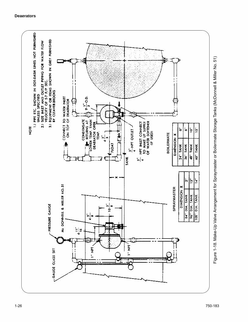
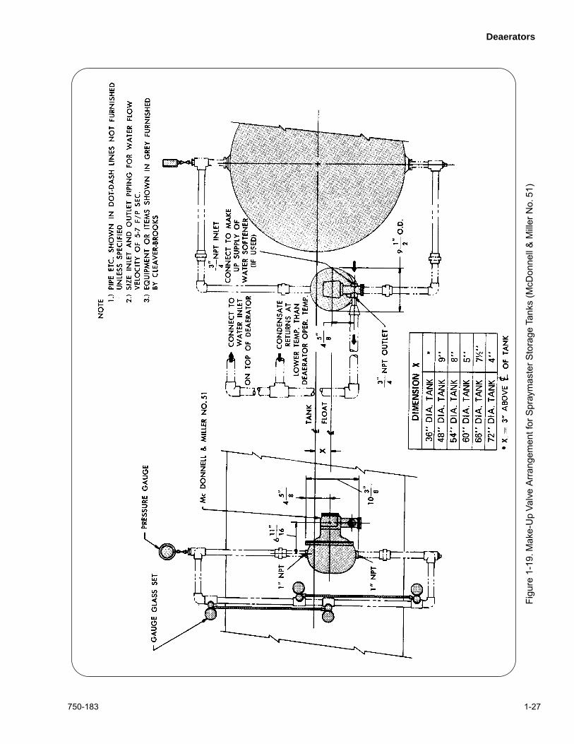
The turnbuckle linking the level regulator to the make-upvalve must be adjusted to close the valve at the proper waterlevel. Refer to Figures 1-18 and 1-19 to determine the desiredwater level for the particular size tank.
When the correct water level is reached, open the pumpvalves and start the feed water pump to fill the boiler. Observethe water level during this process to assure that the pumpdoes not run dry.
Fire the boiler and bring it up to operating pressure inaccordance with good practice and the boiler manufacturer'srecommendations.
When normal operating pressure is obtained, adjust the steampressure reducing valve to provide 5 psig within the tank. Seeadjustment procedures.
Close the vent cock on the drainer when steam begins to flowfrom it.
If the manual vent valve was opened, it should now be closedto provide the desired rate of venting. The orifice in the valvegate will provide a predetermined and sufficient vent rate.
! DANGERCAUTION
Be sure that the orifice ent valve supplied withthe unit is installed. Damage to the equipmentcould result.
1.4.5 Operation and Adjustments
For deaeration to occur, it is necessary to raise thetemperature of the incoming water to a point where oxygenand carbon dioxide are released from the water. This isaccomplished by spraying the water into a steam filledchamber and through a spray of high velocity steam.
Suitable deaeration will take place if the operating pressurewithin the tank is maintained at 5 psig and 227° F.
NOTE
: 227° F is the satur ation temperature ofsteam at 5 psig. Although operation is possible
Deaerators
1-14 750-183
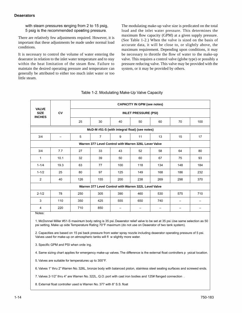
VALVE SIZE
INCHESCV
CAPACITY IN GPM (see notes)
INLET PRESSURE (PSI)
25 30 40 50 60 70 100
McD-M #51-S (with integral float) (see notes)
3/4 – 5 7 9 11 13 15 17
Warren 377 Level Control with Warren 326L Lever Valve
3/4 7.7 27 33 43 52 58 64 80
1 10.1 32 39 50 60 67 75 93
1-1/4 19.3 63 77 100 118 134 148 184
1-1/2 25 80 97 125 149 168 186 232
2 40 126 155 200 238 269 298 370
Warren 377 Level Control with Warren 322L Level Valve
2-1/2 78 250 305 390 460 530 575 710
3 110 350 425 555 650 740 – –
4 220 710 850 – – – – –Notes:
1. McDonnel Miller #51-S maximum body rating is 35 psi. Deaerator relief valve to be set at 35 psi. Use same selection as 50 psi setting. Make up side Temperature Rating 70°F maximum (do not use on Deaerator of two tank system).
2. Capacities are based on 15 psi back pressure from water spray nozzle including deaerator operating pressure of 5 psi. Valves used for make-up on atmospheric tanks will fl w slightly more water.
3. Specific GPM and PSI when orde ing.
4. Same sizing chart applies for emergency make-up valves. The difference is the external float controllers p ysical location.
5. Valves are suitable for temperatures up to 300°F.
6. Valves 1” thru 2” Warren No. 326L, bronze body with balanced piston, stainless steel seating surfaces and screwed ends.
7. Valves 2-1/2” thru 4” are Warren No. 322L, Q.O. port with cast iron bodies and 125# flanged connection .
8. External float controller used is Warren No. 377 with 8” S.S. float
with steam pressures ranging from 2 to 15 psig,5 psig is the recommended operating pressure.
There are relatively few adjustments required. However, it isimportant that these adjustments be made under normal loadconditions.
It is necessary to control the volume of water entering thedeaerator in relation to the inlet water temperature and to staywithin the heat limitation of the steam flow. Failure tomaintain the desired operating pressure and temperature cangenerally be attributed to either too much inlet water or toolittle steam.
The modulating make-up valve size is predicated on the totalload and the inlet water pressure. This determines themaximum flow capacity (GPM) at a given supply pressure.(See Table 1-2.) When the valve is sized on the basis ofaccurate data, it will be close to, or slightly above, themaximum requirement. Depending upon conditions, it maybe necessary to throttle the flow of water to the make-upvalve. This requires a control valve (globe type) or possibly apressure reducing valve. This valve may be provided with thesystem, or it may be provided by others.
Table 1-2. Modulating Make-Up Valve Capacity
Deaerators
750-183 1-15
When throttling is necessary, an initial adjustment madewhen the boiler, or boilers, are operating at capacity isnormally sufficient. Manually adjust the control valve so thata fairly stable water level will be maintained under themaximum load. The make-up valve will modulate to maintaina relatively constant level under other load conditions.
Always observe the water level in the gauge glass and makeany necessary re-adjustment to maintain the desired level.
If the flow of “cool” water is too great, it will quicklycondense the incoming steam making it difficult to maintainthe desired pressure and temperature.
If the flow is insufficient, due to over-throttling the controlvalve, or from lower than anticipated water pressure, it ispossible for low water to occur. This can cause pumpcavitation – possibly damaging the pump – and eventualboiler shut down.
When the water flow is established under normal loadconditions, adjust the steam pressure regulator to maintain a5 psig pressure within the tank. Adjustment should beperformed in accordance with the recommendation of theregulator manufacturer.
Once the unit has leveled out under normal operatingconditions and the liquid level control is operating
automatically, operation is essentially automatic. No furtheradjustments should be required unless there is a change inoperating conditions. Log book recording of all pressures andtemperatures on a daily basis will alert operating personnel todeviations and the need for adjustments.
If adjustments to make-up or steam flows are necessaryduring normal operation, make the adjustments smoothly insmall increments in order to maintain a good heat balance.
Normally there are no re-adjustments required whenbeginning from a cold start, for example after a week-endshut down.
For a normal shut down, such as a week-end, it is usually onlynecessary to secure the necessary supply, drain, or shut-offvalves and the pumps. Depending upon the installation, itmay be advisable to turn off the boiler feed pump during thisshut down and to close the pump discharge valve. This wi11help prevent any vacuum caused by the cooling boiler waterfrom pulling water from the deaerator, or from draining waterfrom an elevated tank to equalize water levels between theboiler and the tank, or to possibly flood the boilers.
Before resuming operation, verify that all valves are returnedto their normal operating position.
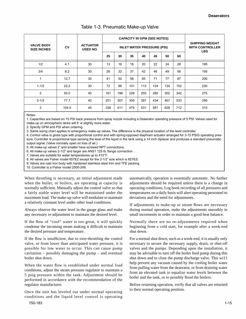
VALVE BODY SIZE INCHES
CVACTUATOR USED NO.
CAPACITY IN GPM (SEE NOTES)
SHIPPING WEIGHT WITH CONTROLLER
LBSINLET WATER PRESSURE (PSI)
25 30 35 40 45 50 60
1/2 4.1 30 13 16 18 20 22 24 28 195
3/4 8.2 30 26 32 37 42 46 49 56 195
1 12.7 30 41 50 58 65 71 77 87 200
1-1/2 22.2 30 72 88 101 113 124 134 152 230
2 50.0 40 161 198 228 255 280 302 342 275
2-1/2 77.7 40 251 307 355 397 434 467 533 290
3 104.0 45 336 411 475 531 581 628 712 315
Notes:1. Capacities are based on 15 PSI back pressure from spray nozzle including a Deaerator operating pressure of 5 PSI. Valves used for make-up on atmospheric tanks will fl w slightly more water.2. Specify GPM and PSI when ordering.3. Same sizing chart applies to emergency make-up valves. The difference is the physical location of the level controller.4. Control valve is globe type with proportional control and with spring-opposed diaphram actuator arranged for 3-15 PSIG operating pres-sure. Controller is proportional type sensing the level of the liquid in the tank using a 14 inch diplacer and produces a standard pneumatic output signal. (Valve normally open on loss of air.)5. All make-up valves 2” and smaller have screwed NPT connections.6. All make-up valves 2-1/2” and larger are ANS1 125 lb. flange connection .7. Valves are suitable for water temperatures up to 410°F.8. All valves are Fisher model 657EZ except for the 2-1/2” size which is 657ES.9. Valves are cast iron body with hardened stainless steel trim and TFE packing.10. Controller is a Fisher model 2500-249.
Table 1-3. Pneumatic Make-up Valve
Deaerators
1-16 750-183
Depending upon conditions, ambient temperature, length ofshut down, etc. the water temperature in the deaerator tankmay have cooled considerably. Because of the advantage offeeding hot deaerated water to the boiler as soon as possible,it may be desirable to speed up heating of the water morequickly than normal operation will accomplish. This can bedone as soon as steam is available by manually operating thedrain valve to dump water so that make-up water and steamwill enter. Care must be taken not to overload the system or tostarve the pump. When the desired operating temperature andpressure are obtained be sure to tightly shut the drain valve.
During shut downs, especially seasonal or extended periods,chemical treatment of the water in the deaerator isrequired.Your feedwater consultant’s recommendationsregarding the use of an oxygen scavenger should be followed.
1.5 MAINTENANCE
Cleaver-Brooks equipment is designed, engineered, and builtto provide long life and excellent service on the job. Goodoperating practices and conscientious maintenance and carewill obtain efficiency and economy from their operation andcontribute to long years of performance.
A well planned maintenance program avoids unnecessarydown time or costly repairs, promotes safety, and aids boilercode and local inspectors. An inspection schedule with al ist ing of procedures should be establ ished. I t isrecommended that a boiler room log, or record, bemaintained. Recording of daily, weekly, monthly and yearlymaintenance activities provides a valuable guide and aids inobtaining economies and length of service from Cleaver-Brooks equipment.
Even though the deaerator has electrical and mechanicaldevices that make it operate automatically, these devicesrequire systematic and periodic maintenance. Any“automatic” features do not relieve the operator fromresponsibility, but rather free him of some repetitive chores,providing time to devote to maintenance.
Only trained and authorized personnel should be permitted tooperate, adjust or repair the boiler and its related equipment.
Good housekeeping helps maintain a professional appearingboiler room. The boiler room should be kept free of allmaterial and equipment not necessary to the operation of theboiler or heating system.
Alertness in recognizing unusual noises, improper gaugereading, leaks, etc., can make the operator aware of adeveloping malfunction, permitting prompt corrective actionthat may prevent extensive repairs or unexpected down time.Any steam, water or fuel leaks should be repaired as soon asthey are noticed. These are wasteful as well as hazardous.Include in the program preventive maintenance measuressuch as regularly checking the tightness of connections,locknuts, setscrews, packing glands, etc.
Insurance regulations or local laws may require a periodicinspection of the pressure vessel by an authorized inspector.
Inspections of this type are usually, though not necessarily,scheduled for periods of normal boiler down time such as anoff season. This major inspection can often be used toaccomplish maintenance, replacements, or repairs that cannoteasily be done at other
times. This also serves as a good basisfor establishing a schedule for annual, monthly, or otherperiodic maintenance programs.
While this inspection pertains primarily to the waterside andfireside surfaces of the boiler, it provides an excellentopportunity for detailed inspection and checking of allcomponents of the system including piping, valves, pumps,gaskets, softener, etc. Comprehensive cleaning, spot paintingor re-painting, and the replacement of expendable items,should be planned for and taken care of during this time. Anymajor repairs or replacements that may be required shouldalso, if possible, be coordinated with this period of boilershutdown.
Replacement spare parts, if not on hand, should be orderedsufficiently prior to shutdown.
Water and steam passing through the deaerator are normallyof high purity. The necessity for cleaning should beinfrequent. The internal parts of the spray nozzle, the steamatomizing valve, and the water collector are constructed ofstainless steel and normally require no maintenance orcleaning. Nevertheless, the interior of the tank and the sprayassembly should be inspected at least annually for anyevidence of corrosion, scaling or other damage.
In the event there is an accumulation of sediment, sand,gravel, etc. in the bottom of the tank, it should be removed,analyzed, and an effort made to eliminate the source.
Should scale be present, the method of cleaning, eithermechanical or chemical, will be governed by the compositionof the scale and its location. If cleaning is required, it issuggested that the cleaning problem be referred to a companythat is versed in this type of cleaning. They will be able todetermine the composition of the scale and will select theproper chemicals to be employed in the cleaning process.
Periodic checks for water softness should be maintained. Ifhardness exceeds three grains per gallon, a water softenershould be used to prevent build up of mineral deposits on theinternal parts of the deaerator.
The water spray nozzle is of the self-cleaning type. Cloggingor wearing seldom occurs, however, it is a possibility thatshould be checked in the event problems are encountered.This is a spring-loaded valve and it is factory pre-set. Shoulddisassembly or adjustment become necessary, tighten thespring with the spray disc closed, compressing it 3/16". Besure that the jam nut locks tightly against the adjusting nut.
Deaerators
750-183 1-17
NOTE: For the Spraymaster only!
Spring compression for the steam atomizingvalve (on deaerators so equipped) is factory setand does not nor mally require alter ation. Ifpossible, this dimension should be rechec kedwhen the deaerator is installed, and again priorto operation since the adjusting nuts may havevibrated loose during shipment or installation. Itshould be rechec ked dur ing an inter nalinspection or if an y problem is encountered.The compressed spring length is as follows:
The lock nut on the top end of the v alve rodshould fit tightly against the steam duct so thathe valve seat is held in the proper position
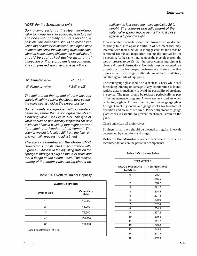
Some models are equipped with a counter-balanced, rather than a spr ing-loaded steamatomizing valve. (See Figure 1-7). This type ofvalve should be per iodically inspected for anyevidence of scale b uild up that might pre venttight closing or freedom of mo vement. Thecounter weight is located 28" from the fulcr umand normally requires no adjustment.
The spray assembly for the Model SM-7Deaerator is constr ucted in accordance withFigure 1-9. Access to the adjusting nuts on thesprings is through a plug on the water valve andthru a flange on the steam alve. The tensionsetting of the steam v alve spr ing should be
sufficient to just close the alve against a 20 lbweight. The compression adjustment of thewater valve spring should permit it to just closeagainst a 1 pound weight.
Float-operated controls should be blown down or drainedroutinely to assure against build up of sediment that mayinterfere with their function. It is suggested that the heads beremoved for visual inspection during the annual boilerinspection. At the same time, remove the pipe plugs from thetees or crosses to verify that the cross connecting piping isclean and free of obstructions. Controls must be mounted in aplumb position for proper performance. Determine thatpiping is vertically aligned after shipment and installation,and throughout life of equipment.
The water gauge glass should be kept clean. Check while coolfor etching thinning or damage. If any deterioration is found,replace glass immediately to avoid the possibility of breakagein service. The glass should be replaced periodically as partof the maintenance program. Always use new gaskets whenreplacing a glass. Do not over tighten water gauge glassfittings. Check try-cocks and gauge cocks for freedom ofoperation and clean as required. Proper alignment of gaugeglass cocks is essential to prevent mechanical strain on theglass.
Check and clean all drain valves.
Strainers in all lines should be cleaned at regular intervalsdetermined by conditions and usage.
Refer to the Manufacturer’s l i terature for servicerecommendations on the particular components.
6" diameter valve 6" ± 1/8"
8" diameter valve 7-5/8" ± 1/8"
WARREN TYPE 313
Drainer SizeCapacity in
lb/hr
1” 10,000
2” 45,000
3” 78,500
4” 138,000
6” 293,000
Based on differential of 5 psi
Table 1-4. Overfl w Drainer Capacity
STEAM TABLE
GAUGE PRESSURE LB/SQ IN.
TEMPERATURE °F
0 212.1 215.52 218.73 221.74 224.55 227.36 229.97 232.48 234.99 237.210 239.511 241.712 243.813 245.914 247.915 249.8
Table 1-5. Steam Table
Deaerators
1-18 750-183
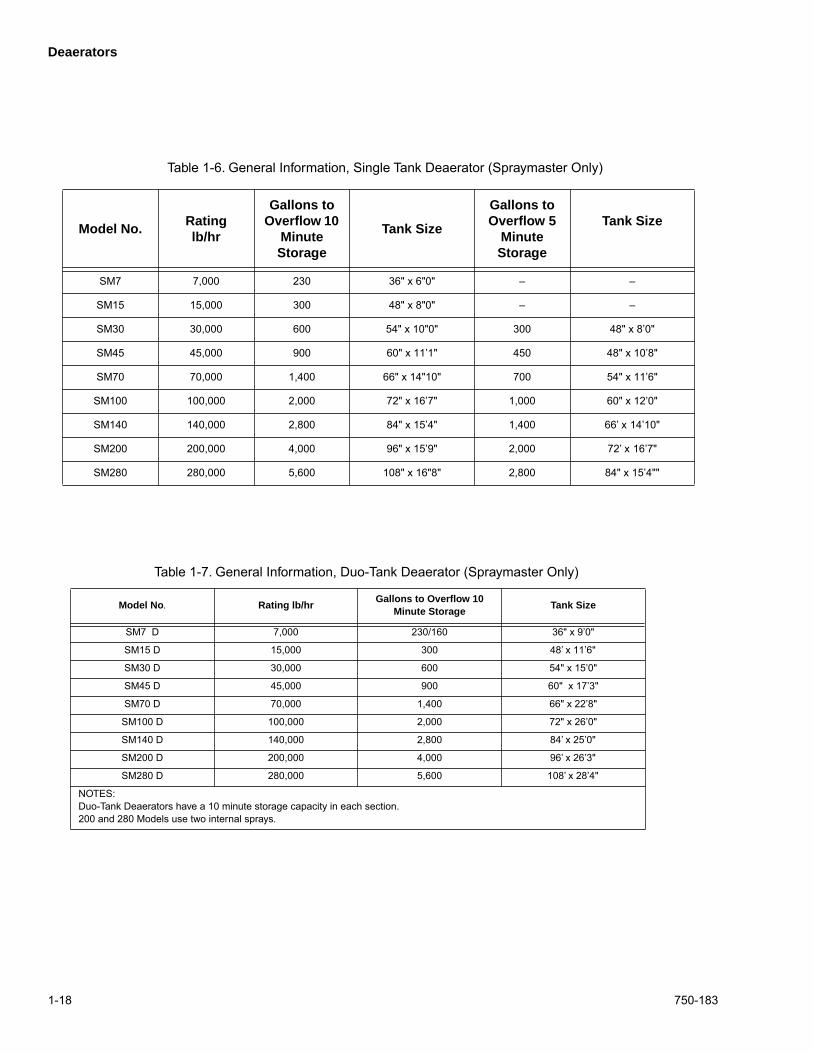
Model No.Rating lb/hr
Gallons to Overflow 10
Minute Storage
Tank Size
Gallons to Overflow 5
Minute Storage
Tank Size
SM7 7,000 230 36" x 6"0" – –
SM15 15,000 300 48" x 8"0" – –
SM30 30,000 600 54" x 10"0" 300 48" x 8’0"
SM45 45,000 900 60" x 11’1" 450 48" x 10’8"
SM70 70,000 1,400 66" x 14"10" 700 54" x 11’6"
SM100 100,000 2,000 72" x 16’7" 1,000 60" x 12’0"
SM140 140,000 2,800 84" x 15’4" 1,400 66’ x 14’10"
SM200 200,000 4,000 96" x 15’9" 2,000 72’ x 16’7"
SM280 280,000 5,600 108" x 16"8" 2,800 84" x 15’4""
Table 1-6. General Information, Single Tank Deaerator (Spraymaster Only)
Model No
.
Rating lb/hrGallons to Overflow 10
Minute StorageTank Size
SM7 D 7,000 230/160 36" x 9’0"
SM15 D 15,000 300 48’ x 11’6"
SM30 D 30,000 600 54" x 15’0"
SM45 D 45,000 900 60" x 17’3"
SM70 D 70,000 1,400 66" x 22’8"
SM100 D 100,000 2,000 72" x 26’0"
SM140 D 140,000 2,800 84’ x 25’0"
SM200 D 200,000 4,000 96’ x 26’3"
SM280 D 280,000 5,600 108’ x 28’4"
NOTES:Duo-Tank Deaerators have a 10 minute storage capacity in each section.200 and 280 Models use two internal sprays.
Table 1-7. General Information, Duo-Tank Deaerator (Spraymaster Only)
Deaerators
750-183 1-19
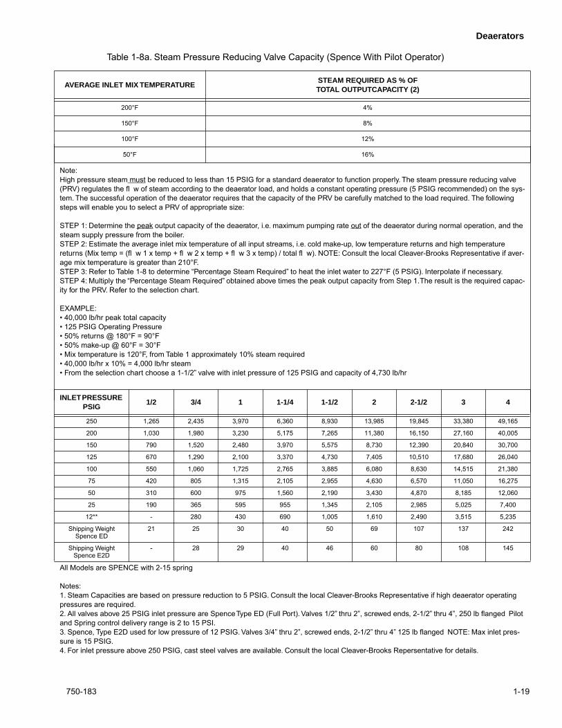
AVERAGE INLET MIX TEMPERATURESTEAM REQUIRED AS % OF TOTAL OUTPUTCAPACITY (2)
200°F 4%
150°F 8%
100°F 12%
50°F 16%
Note:High pressure steam must be reduced to less than 15 PSIG for a standard deaerator to function properly. The steam pressure reducing valve (PRV) regulates the fl w of steam according to the deaerator load, and holds a constant operating pressure (5 PSIG recommended) on the sys-tem. The successful operation of the deaerator requires that the capacity of the PRV be carefully matched to the load required. The following steps will enable you to select a PRV of appropriate size:
STEP 1: Determine the peak output capacity of the deaerator, i.e. maximum pumping rate out of the deaerator during normal operation, and the steam supply pressure from the boiler.STEP 2: Estimate the average inlet mix temperature of all input streams, i.e. cold make-up, low temperature returns and high temperature returns (Mix temp = (fl w 1 x temp + fl w 2 x temp + fl w 3 x temp) / total fl w). NOTE: Consult the local Cleaver-Brooks Representative if aver-age mix temperature is greater than 210°F.STEP 3: Refer to Table 1-8 to determine “Percentage Steam Required” to heat the inlet water to 227°F (5 PSIG). Interpolate if necessary.STEP 4: Multiply the “Percentage Steam Required” obtained above times the peak output capacity from Step 1. The result is the required capac-ity for the PRV. Refer to the selection chart.
EXAMPLE:• 40,000 lb/hr peak total capacity• 125 PSIG Operating Pressure• 50% returns @ 180°F = 90°F• 50% make-up @ 60°F = 30°F• Mix temperature is 120°F, from Table 1 approximately 10% steam required• 40,000 lb/hr x 10% = 4,000 lb/hr steam• From the selection chart choose a 1-1/2” valve with inlet pressure of 125 PSIG and capacity of 4,730 lb/hr
Table 1-8a. Steam Pressure Reducing Valve Capacity (Spence With Pilot Operator)
INLET PRESSURE PSIG
1/2 3/4 1 1-1/4 1-1/2 2 2-1/2 3 4
250 1,265 2,435 3,970 6,360 8,930 13,985 19,845 33,380 49,165
200 1,030 1,980 3,230 5,175 7,265 11,380 16,150 27,160 40,005
150 790 1,520 2,480 3,970 5,575 8,730 12,390 20,840 30,700
125 670 1,290 2,100 3,370 4,730 7,405 10,510 17,680 26,040
100 550 1,060 1,725 2,765 3,885 6,080 8,630 14,515 21,380
75 420 805 1,315 2,105 2,955 4,630 6,570 11,050 16,275
50 310 600 975 1,560 2,190 3,430 4,870 8,185 12,060
25 190 365 595 955 1,345 2,105 2,985 5,025 7,400
12** - 280 430 690 1,005 1,610 2,490 3,515 5,235
Shipping Weight Spence ED
21 25 30 40 50 69 107 137 242
Shipping Weight Spence E2D
- 28 29 40 46 60 80 108 145
All Models are SPENCE with 2-15 spring
Notes:1. Steam Capacities are based on pressure reduction to 5 PSIG. Consult the local Cleaver-Brooks Representative if high deaerator operating pressures are required.2. All valves above 25 PSIG inlet pressure are Spence Type ED (Full Port). Valves 1/2” thru 2”, screwed ends, 2-1/2” thru 4”, 250 lb flanged Pilot and Spring control delivery range is 2 to 15 PSI.3. Spence, Type E2D used for low pressure of 12 PSIG. Valves 3/4” thru 2”, screwed ends, 2-1/2” thru 4” 125 lb flanged NOTE: Max inlet pres-sure is 15 PSIG.4. For inlet pressure above 250 PSIG, cast steel valves are available. Consult the local Cleaver-Brooks Repersentative for details.
Deaerators
1-20 750-183
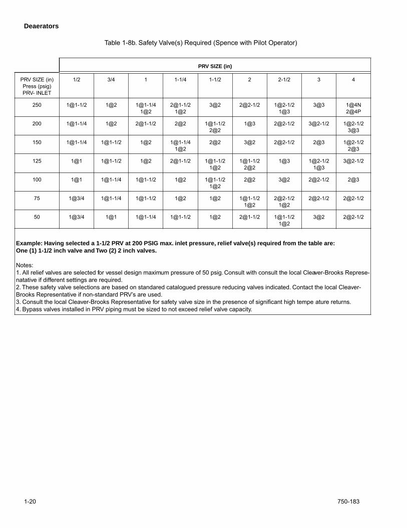
PRV SIZE (in)
PRV SIZE (in)Press (psig)PRV- INLET
1/2 3/4 1 1-1/4 1-1/2 2 2-1/2 3 4
250 1@1-1/2 1@2 1@1-1/41@2
2@1-1/21@2
3@2 2@2-1/2 1@2-1/21@3
3@3 1@4N2@4P
200 1@1-1/4 1@2 2@1-1/2 2@2 1@1-1/22@2
1@3 2@2-1/2 3@2-1/2 1@2-1/23@3
150 1@1-1/4 1@1-1/2 1@2 1@1-1/41@2
2@2 3@2 2@2-1/2 2@3 1@2-1/22@3
125 1@1 1@1-1/2 1@2 2@1-1/2 1@1-1/21@2
1@1-1/22@2
1@3 1@2-1/21@3
3@2-1/2
100 1@1 1@1-1/4 1@1-1/2 1@2 1@1-1/21@2
2@2 3@2 2@2-1/2 2@3
75 1@3/4 1@1-1/4 1@1-1/2 1@2 1@2 1@1-1/21@2
2@2-1/21@2
2@2-1/2 2@2-1/2
50 1@3/4 1@1 1@1-1/4 1@1-1/2 1@2 2@1-1/2 1@1-1/21@2
3@2 2@2-1/2
Example: Having selected a 1-1/2 PRV at 200 PSIG max. inlet pressure, relief valve(s) required from the table are:One (1) 1-1/2 inch valve and Two (2) 2 inch valves.
Notes: 1. All relief valves are selected for vessel design maximum pressure of 50 psig. Consult with consult the local Cleaver-Brooks Represe-natative if different settings are required.2. These safety valve selections are based on standared catalogued pressure reducing valves indicated. Contact the local Cleaver-Brooks Representative if non-standard PRV’s are used.3. Consult the local Cleaver-Brooks Representative for safety valve size in the presence of significant high tempe ature returns.4. Bypass valves installed in PRV piping must be sized to not exceed relief valve capacity.
Table 1-8b. Safety Valve(s) Required (Spence with Pilot Operator)
Deaerators
750-183 1-21
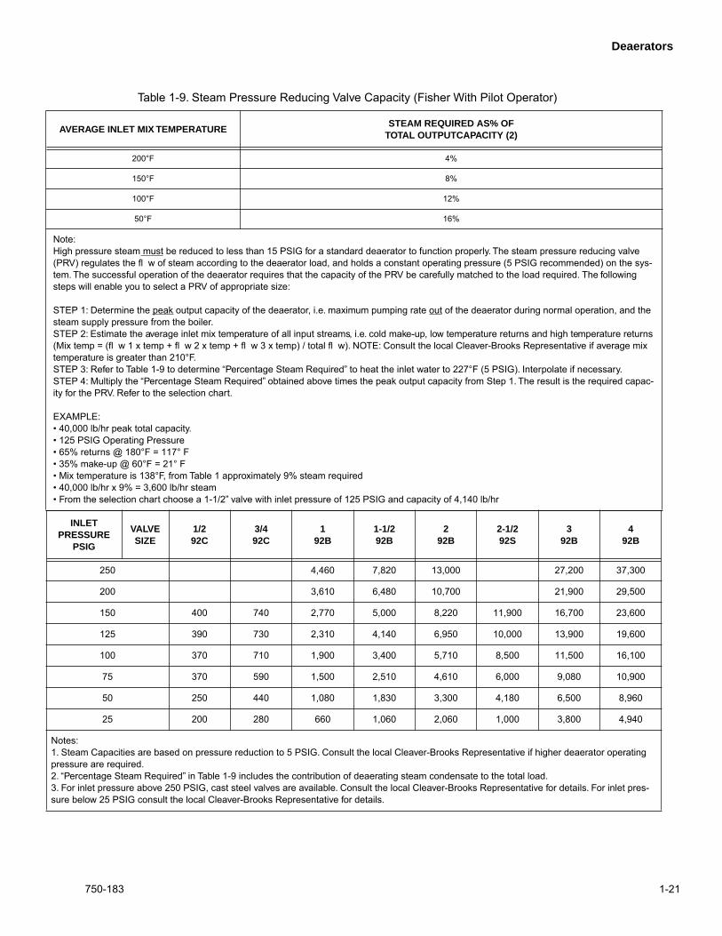
AVERAGE INLET MIX TEMPERATURESTEAM REQUIRED AS% OF
TOTAL OUTPUTCAPACITY (2)
200°F 4%
150°F 8%
100°F 12%
50°F 16%
Note:High pressure steam must be reduced to less than 15 PSIG for a standard deaerator to function properly. The steam pressure reducing valve (PRV) regulates the fl w of steam according to the deaerator load, and holds a constant operating pressure (5 PSIG recommended) on the sys-tem. The successful operation of the deaerator requires that the capacity of the PRV be carefully matched to the load required. The following steps will enable you to select a PRV of appropriate size:
STEP 1: Determine the peak output capacity of the deaerator, i.e. maximum pumping rate out of the deaerator during normal operation, and the steam supply pressure from the boiler.STEP 2: Estimate the average inlet mix temperature of all input streams, i.e. cold make-up, low temperature returns and high temperature returns (Mix temp = (fl w 1 x temp + fl w 2 x temp + fl w 3 x temp) / total fl w). NOTE: Consult the local Cleaver-Brooks Representative if average mix temperature is greater than 210°F.STEP 3: Refer to Table 1-9 to determine “Percentage Steam Required” to heat the inlet water to 227°F (5 PSIG). Interpolate if necessary.STEP 4: Multiply the “Percentage Steam Required” obtained above times the peak output capacity from Step 1. The result is the required capac-ity for the PRV. Refer to the selection chart.
EXAMPLE:• 40,000 lb/hr peak total capacity.• 125 PSIG Operating Pressure• 65% returns @ 180°F = 117° F• 35% make-up @ 60°F = 21° F• Mix temperature is 138°F, from Table 1 approximately 9% steam required• 40,000 lb/hr x 9% = 3,600 lb/hr steam• From the selection chart choose a 1-1/2” valve with inlet pressure of 125 PSIG and capacity of 4,140 lb/hr
Table 1-9. Steam Pressure Reducing Valve Capacity (Fisher With Pilot Operator)
INLET PRESSURE
PSIG
VALVESIZE
1/292C
3/492C
192B
1-1/292B
292B
2-1/292S
392B
492B
250 4,460 7,820 13,000 27,200 37,300
200 3,610 6,480 10,700 21,900 29,500
150 400 740 2,770 5,000 8,220 11,900 16,700 23,600
125 390 730 2,310 4,140 6,950 10,000 13,900 19,600
100 370 710 1,900 3,400 5,710 8,500 11,500 16,100
75 370 590 1,500 2,510 4,610 6,000 9,080 10,900
50 250 440 1,080 1,830 3,300 4,180 6,500 8,960
25 200 280 660 1,060 2,060 1,000 3,800 4,940
Notes:1. Steam Capacities are based on pressure reduction to 5 PSIG. Consult the local Cleaver-Brooks Representative if higher deaerator operating pressure are required.2. “Percentage Steam Required” in Table 1-9 includes the contribution of deaerating steam condensate to the total load.3. For inlet pressure above 250 PSIG, cast steel valves are available. Consult the local Cleaver-Brooks Representative for details. For inlet pres-sure below 25 PSIG consult the local Cleaver-Brooks Representative for details.
Deaerators
1-22 750-183
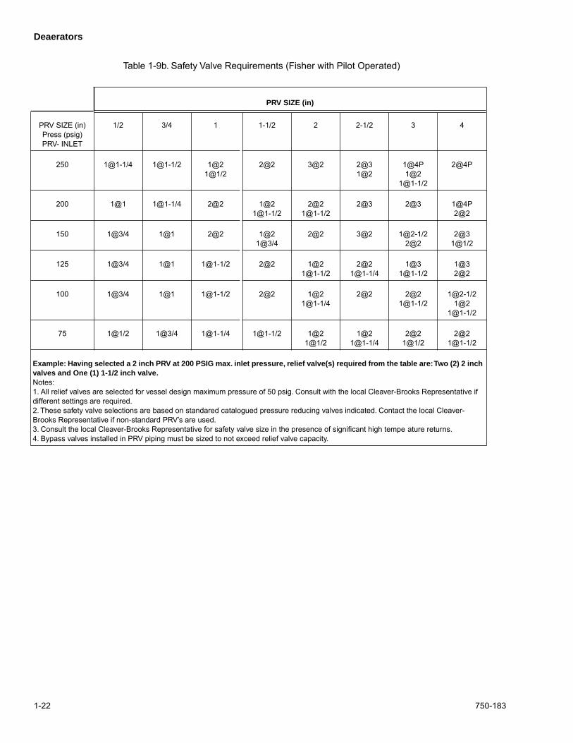
PRV SIZE (in)
PRV SIZE (in)Press (psig)PRV- INLET
1/2 3/4 1 1-1/2 2 2-1/2 3 4
250 1@1-1/4 1@1-1/2 1@21@1/2
2@2 3@2 2@31@2
1@4P1@2
1@1-1/2
2@4P
200 1@1 1@1-1/4 2@2 1@21@1-1/2
2@21@1-1/2
2@3 2@3 1@4P2@2
150 1@3/4 1@1 2@2 1@21@3/4
2@2 3@2 1@2-1/22@2
2@31@1/2
125 1@3/4 1@1 1@1-1/2 2@2 1@21@1-1/2
2@21@1-1/4
1@31@1-1/2
1@32@2
100 1@3/4 1@1 1@1-1/2 2@2 1@21@1-1/4
2@2 2@21@1-1/2
1@2-1/21@2
1@1-1/2
75 1@1/2 1@3/4 1@1-1/4 1@1-1/2 1@21@1/2
1@21@1-1/4
2@21@1/2
2@21@1-1/2
Example: Having selected a 2 inch PRV at 200 PSIG max. inlet pressure, relief valve(s) required from the table are: Two (2) 2 inch valves and One (1) 1-1/2 inch valve.
Notes: 1. All relief valves are selected for vessel design maximum pressure of 50 psig. Consult with the local Cleaver-Brooks Representative if different settings are required.2. These safety valve selections are based on standared catalogued pressure reducing valves indicated. Contact the local Cleaver-Brooks Representative if non-standard PRV’s are used.3. Consult the local Cleaver-Brooks Representative for safety valve size in the presence of significant high tempe ature returns.4. Bypass valves installed in PRV piping must be sized to not exceed relief valve capacity.
Table 1-9b. Safety Valve Requirements (Fisher with Pilot Operated)
Deaerators
750-183 1-23
InletPressPSIG
Valve Body Size 1" 1-1/2" 2" 2-1/2" 3" 4"
Orifice Si e 1/2" 3/4" 1 1-1/2 1-1/2 2-7/8" 3 4
Inst. Air Req’d
3 – 15 6 – 30
300 2100Size 30
4500Size 30
7000Size 30
12500Size 34
30000Size 45
45000Size 70
275 1900Size 30
4000Size 30
6500Size 30
11000Size 34
28000Size 45
42000Size 70
250 1750Size 30
3750Size 30
5900Size 30
10000Size 34
25000Size 45
38000Size 70
225 1600Size 30
3400Size 30
5300Size 30
9300Size 34
23000Size 45
35000Size 70
44000Size 70
200 1400Size 30
3100Size 30
4800Size 30
8500Size 34
20500Size 45
27000Size 70
44000Size 70
175 1250Size 30
2700Size 30
4200Size 30
7400Size 34
18000Size 45
27000Size 70
35000Size 70
150 1100Size 30
2350Size 30
3700Side 30
6500Size 34
15500Size 45
23500Size 45
30000Size 70
100 940Size 30
1950Size 30
3000Size 30
5500Size 34
13000Size 45
20000Size 45
26000Side 45
42500Size 70
75 740Size 30
1600Size 30
2500Size 30
4500Size 34
11000Size 40
16500Size 45
21000Size 45
35000Size 70
55 580Size 30
1200Size 30
1900Size 30
3400Size 34
8400Size 40
12500Size 45
16000Size 45
27000Size 70
50 420Size 30
900Size 30
1400Size 30
2300Size 34
6000Size 40
9000Size 45
11500Size 45
19000Size 70
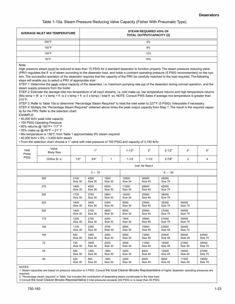
NOTES:1. Steam capacities are based on pressure reduction to 5 PSIG. Consult
the local Cleaver-Brooks Representative
of higher deaerator operating pressures are required.2. “Percentage steam required” in Table 10a includes the contribution of deaerating steam condensate to the total load.3.Consult
the local Cleaver-Brooks Representative
if inlet pressures exceeds 300 PSIG or is lower than 50 PSIG.
AVERAGE INLET MIX TEMPERATURESTEAM REQUIRED AS% OF
TOTAL OUTPUTCAPACITY (2)
200°F 4%
150°F 8%
100°F 12%
50°F 16%
Note:High pressure steam must be reduced to less than 15 PSIG for a standard deaerator to function properly. The steam pressure reducing valve (PRV) regulates the fl w of steam according to the deaerator load, and holds a constant operating pressure (5 PSIG recommended) on the sys-tem. The successful operation of the deaerator requires that the capacity of the PRV be carefully matched to the load required. The following steps will enable you to select a PRV of appropriate size:STEP 1: Determine the peak output capacity of the deaerator, i.e. maximum pumping rate out of the deaerator during normal operation, and the steam supply pressure from the boiler.STEP 2: Estimate the average inlet mix temperature of all input streams, i.e. cold make-up, low temperature returns and high temperature returns (Mix temp = (fl w 1 x temp + fl w 2 x temp + fl w 3 x temp) / total fl w). NOTE: Consult PWS Sales if average mix temperature is greater than 210°F.STEP 3: Refer to Table 10a to determine “Percentage Steam Required” to heat the inlet water to 227°F (5 PSIG). Interpolate if necessary.STEP 4: Multiply the “Percentage Steam Required” obtained above times the peak output capacity from Step 1. The result is the required capac-ity for the PRV. Refer to the selection chart.EXAMPLE:• 40,000 lb/hr peak total capacity • 150 PSIG Operating Pressure • 65% returns @ 180°F= 117° F• 35% make-up @ 60°F = 21° F• Mix temperature is 138°F, from Table 1 approximately 9% steam required• 40,000 lb/hr x 9% = 3,600 lb/hr steam• From the selection chart choose a 1” valve with inlet pressure of 150 PSIG and capacity of 3,740 lb/hr
Table 1-10a. Steam Pressure Reducing Valve Capacity (Fisher With Pneumatic Type)
Deaerators
1-24 750-183
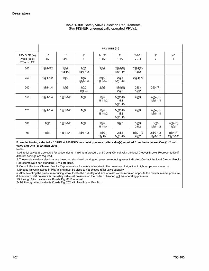
PRV SIZE (in)
PRV SIZE (in)Press (psig)PRV- INLET
1”1/2
1”3/4
1”1
1-1/2”1-1/2
2”1-1/2
2-1/2”2-7/8
3”3
4”4
300 1@1-/12 1@21@1/2
1@21@1-1/2
3@2 2@4(N)1@1-1/4
2@4(P)1@2
250 1@1-1/2 1@2 1@21@1-1/4
2@21@1-1/4
2@31@1-1/4
2@4(P)
200 1@1-1/4 1@2 1@21@3/4
2@2 1@4(N)2@2
2@31@2
2@4(P)
150 1@1-1/4 1@1-1/2 1@2 1@21@1-1/2
1@2-1/21@2
1@1-1/2
2@3 2@4(N)1@1-1/4
125 1@1-1/4 1@1-1/2 1@2 1@21@1-1/2
1@2-1/21@2
1@1-1/2
2@3 2@4(N)1@1-1/4
100 1@1 1@1-1/2 1@2 1@21@1-1/4
3@2 1@32@2
3@31@1-1/2
2@4(P)1@1
75 1@1 1@1-1/4 1@1-1/2 1@21@1/2
2@21@1-1/2
1@2-1/22@2
2@2-1/21@1-1/2
1@4(P)2@2-1/2
Example: Having selected a 1” PRV at 200 PSIG max. inlet pressure, relief valve(s) required from the table are: One (1) 2 inch valve and One (1) 3/4 inch valve.
Notes: 1. All relief valves are selected for vessel design maximum pressure of 50 psig. Consult with the local Cleaver-Brooks Representative if different settings are required.2. These safety valve selections are based on standared catalogued pressure reducing valves indicated. Contact the local Cleaver-Brooks Representative if non-standard PRV’s are used.3. Consult the local Cleaver-Brooks Representative for safety valve size in the presence of significant high tempe ature returns.4. Bypass valves installed in PRV piping must be sized to not exceed relief valve capacity.5. After selecting the pressure reducing valve, locate the quantity and size of relief valves required opposite the maximum inlet pressure.6. Maximum inlet pressure is the safety valve set pressure on the boiler or header, not the operating pressure.1/2 through 2 inch valves are Kunkle Fig. 6010 or equal.2- 1/2 through 4 inch valve is Kunkle Fig. 252 with N-orifice or P-o ific .
Table 1-10b. Safety Valve Selection Requirements(For FISHER pneumatically operated PRV’s).
Deaerators
750-183 1-25
Figure 1-17. Suggested Piping Arrangement for Boiler Feed Pump
Deaerators
1-26 750-183
Figu
re 1
-18.
Mak
e-U
p Va
lve
Arra
ngem
ent f
or S
pray
mas
ter o
r Boi
lerm
ate
Sto
rage
Tan
ks (M
cDon
nell
& M
iller
No.
51)
SP
RAY
MA
ST
ER
BO
ILE
RM
ATE
Deaerators
750-183 1-27
Figu
re 1
-19.
Mak
e-U
p Va
lve
Arra
ngem
ent f
or S
pray
mas
ter S
tora
ge T
anks
(McD
onne
ll &
Mill
er N
o. 5
1)
Deaerators
1-28 750-183
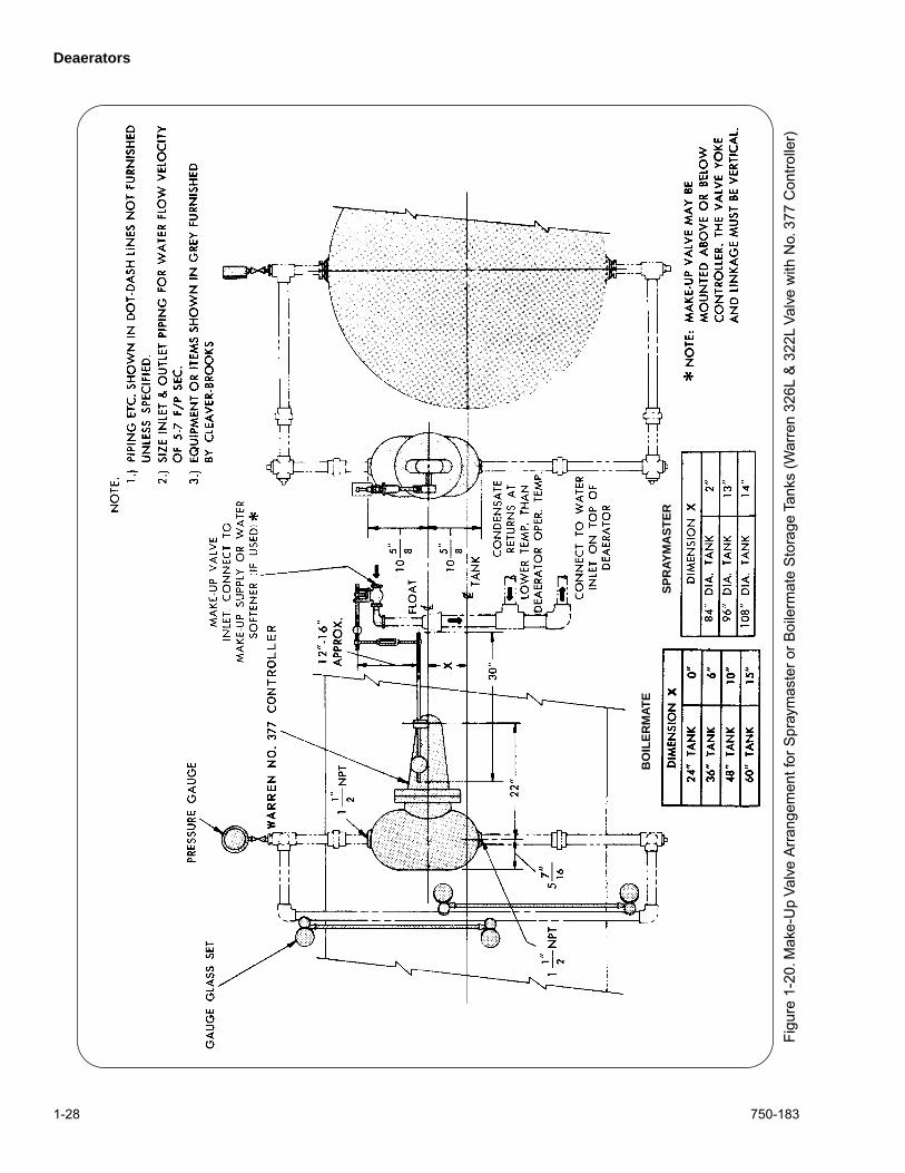
Figu
re 1
-20.
Mak
e-U
p Va
lve
Arra
ngem
ent f
or S
pray
mas
ter o
r Boi
lerm
ate
Sto
rage
Tan
ks (W
arre
n 32
6L &
322
L Va
lve
with
No.
377
Con
trolle
r)
SP
RAY
MA
ST
ER
BO
ILE
RM
ATE
Deaerators
750-183 1-29
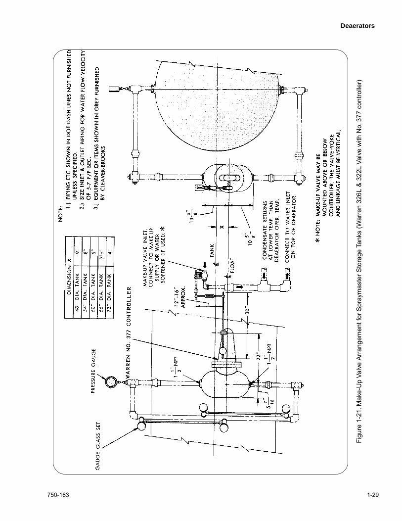
Figu
re 1
-21.
Mak
e-U
p Va
lve
Arra
ngem
ent f
or S
pray
mas
ter S
tora
ge T
anks
(War
ren
326L
& 3
22L
Valv
e w
ith N
o. 3
77 c
ontro
ller)
Deaerators
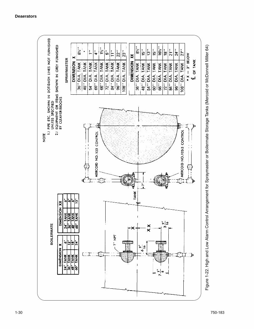
1-30 750-183
Figu
re 1
-22.
Hig
h an
d Lo
w A
larm
Con
trol A
rrang
emen
t for
Spr
aym
aste
r or B
oile
rmat
e S
tora
ge T
anks
(Mer
coid
or M
cDon
nell
Mill
er 6
4)
SP
RAY
MA
ST
ER
BO
ILE
RM
ATE
Pressure Reducing Valves
750-183 2-1
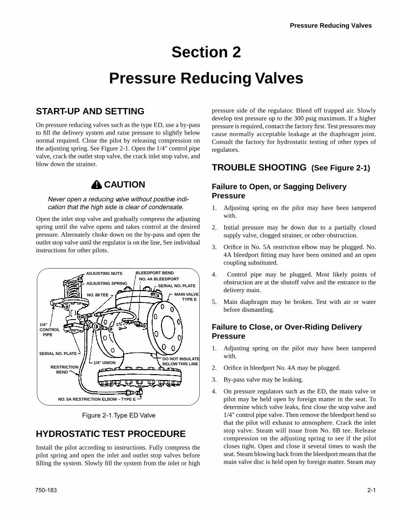
START-UP AND SETTING
On pressure reducing valves such as the type ED, use a by-passto fill the delivery system and raise pressure to slightly belownormal required. Close the pilot by releasing compression onthe adjusting spring. See Figure 2-1. Open the 1/4" control pipevalve, crack the outlet stop valve, the crack inlet stop valve, andblow down the strainer.
! DANGERCAUTION
Never open a reducing valve without positive indi-cation that the high side is clear of condensate.
Open the inlet stop valve and gradually compress the adjustingspring until the valve opens and takes control at the desiredpressure. Alternately choke down on the by-pass and open theoutlet stop valve until the regulator is on the line, See individualinstructions for other pilots.
HYDROSTATIC TEST PROCEDURE
Install the pilot according to instructions. Fully compress thepilot spring and open the inlet and outlet stop valves beforefilling the system. Slowly fill the system from the inlet or high
pressure side of the regulator. Bleed off trapped air. Slowlydevelop test pressure up to the 300 psig maximum. If a higherpressure is required, contact the factory first. Test pressures maycause normally acceptable leakage at the diaphragm joint.Consult the factory for hydrostatic testing of other types ofregulators.
TROUBLE SHOOTING
(See Figure 2-1)
Failure to Open, or Sagging Delivery Pressure
1. Adjusting spring on the pilot may have been tamperedwith.
2. Initial pressure may be down due to a partially closedsupply valve, clogged strainer, or other obstruction.
3. Orifice in No. 5A restriction elbow may be plugged. No.4A bleedport fitting may have been omitted and an opencoupling substituted.
4. Control pipe may be plugged. Most likely points ofobstruction are at the shutoff valve and the entrance to thedelivery main.
5. Main diaphragm may be broken. Test with air or waterbefore dismantling.
Failure to Close, or Over-Riding Delivery Pressure
1. Adjusting spring on the pilot may have been tamperedwith.
2. Orifice in bleedport No. 4A may be plugged.
3. By-pass valve may be leaking.
4. On pressure regulators such as the ED, the main valve orpilot may be held open by foreign matter in the seat. Todetermine which valve leaks, first close the stop valve and1/4" control pipe valve. Then remove the bleedport bend sothat the pilot will exhaust to atmosphere. Crack the inletstop valve. Steam will issue from No. 8B tee. Releasecompression on the adjusting spring to see if the pilotcloses tight. Open and close it several times to wash theseat. Steam blowing back from the bleedport means that themain valve disc is held open by foreign matter. Steam may
ADJUSTING NUTS
ADJUSTING SPRING
NO. 88 TEE
NO. 4A BLEEDPORT
BLEEDPORT BEND
SERIAL NO. PLATE
MAIN VALVE TYPE E
1/4"CONTROL PIPE
SERIAL NO. PLATE
RESTRICTION BEND
1/4" UNION
NO. 5A RESTRICTION ELBOW – TYPE E
DO NOT INSULATE BELOW THIS LINE
Figure 2-1.Type ED Valve
Section 2
Pressure Reducing Valves
Pressure Reducing Valves
2-2 750-183
wash the obstruction from the seat if the valve is made toopen wide. This can be accomplished, even at light loads,if the control point is beyond the outlet stop valve.Reassemble the bleedport bend and place the regulator inoperation. Then, slowly open and close the outlet stopvalve.
MAINTENANCE
Inspection
Under normal conditions, complete dismantling at regularintervals is not recommended. A valve kept relatively free ofdirt will function for years with minimum attention.
After the first few days of operation and twice a year, thefollowing should be checked.
1. Inspect for dirt collected at bleedport No. 4A andrestriction elbow No. 5A (see Figure 2-1).
2. Inspect all joints for leakage. Keep bolts tight. Never allowa leak to persist.
Notes:
750-183 3-1
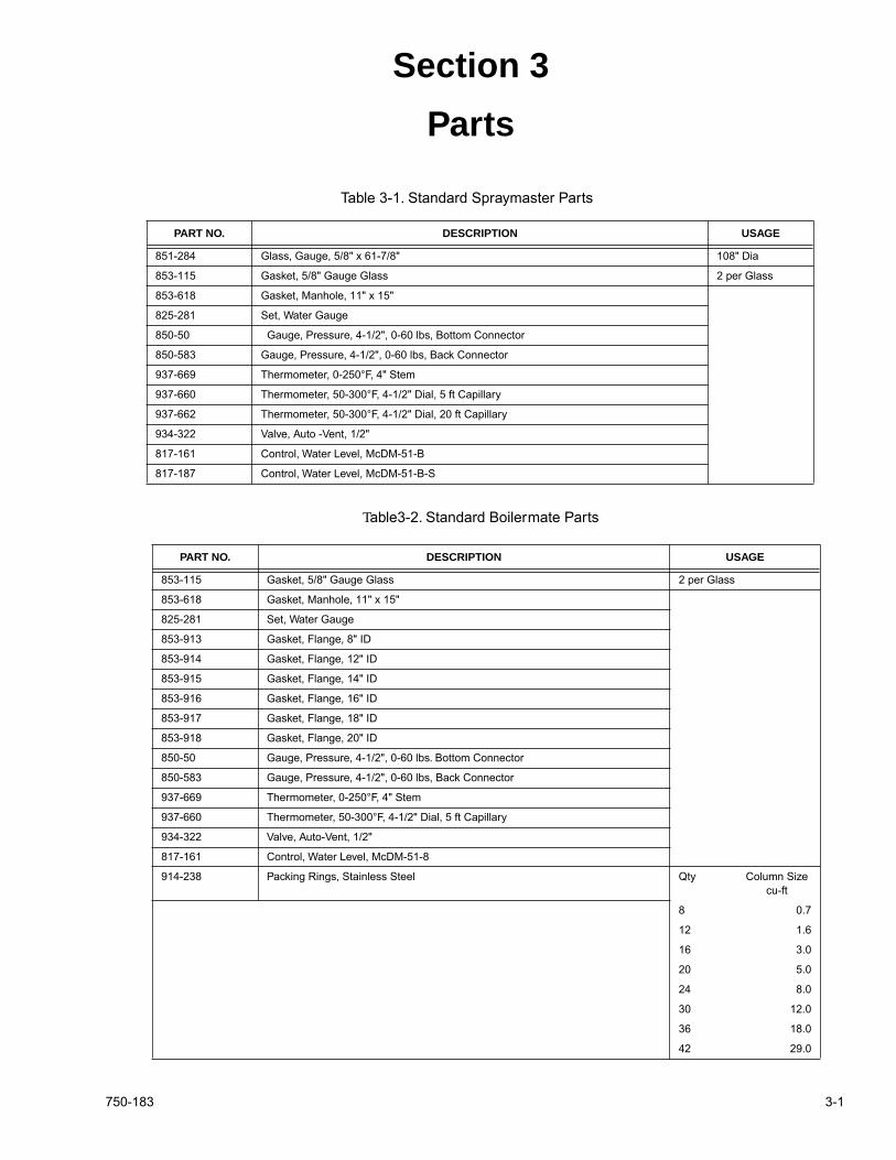
Section 3
Parts
PART NO. DESCRIPTION USAGE
851-284 Glass, Gauge, 5/8" x 61-7/8" 108" Dia
853-115 Gasket, 5/8" Gauge Glass 2 per Glass
853-618 Gasket, Manhole, 11" x 15"
825-281 Set, Water Gauge
850-50 Gauge, Pressure, 4-1/2", 0-60 lbs, Bottom Connector
850-583 Gauge, Pressure, 4-1/2", 0-60 lbs, Back Connector
937-669 Thermometer, 0-250°F, 4" Stem
937-660 Thermometer, 50-300°F, 4-1/2" Dial, 5 ft Capillary
937-662 Thermometer, 50-300°F, 4-1/2" Dial, 20 ft Capillary
934-322 Valve, Auto -Vent, 1/2"
817-161 Control, Water Level, McDM-51-B
817-187 Control, Water Level, McDM-51-B-S
Table 3-1. Standard Spraymaster Parts
T
able3-2. Standard Boilermate Parts
PART NO. DESCRIPTION USAGE
853-115 Gasket, 5/8" Gauge Glass 2 per Glass
853-618 Gasket, Manhole, 11" x 15"
825-281 Set, Water Gauge
853-913 Gasket, Flange, 8" ID
853-914 Gasket, Flange, 12" ID
853-915 Gasket, Flange, 14" ID
853-916 Gasket, Flange, 16" ID
853-917 Gasket, Flange, 18" ID
853-918 Gasket, Flange, 20" ID
850-50 Gauge, Pressure, 4-1/2", 0-60 lbs. Bottom Connector
850-583 Gauge, Pressure, 4-1/2", 0-60 lbs, Back Connector
937-669 Thermometer, 0-250°F, 4" Stem
937-660 Thermometer, 50-300°F, 4-1/2" Dial, 5 ft Capillary
934-322 Valve, Auto-Vent, 1/2"
817-161 Control, Water Level, McDM-51-8
914-238 Packing Rings, Stainless Steel Qty Column Sizecu-ft
8 0.7
12 1.6
16 3.0
20 5.0
24 8.0
30 12.0
36 18.0
42 29.0
Parts
3-2 750-183
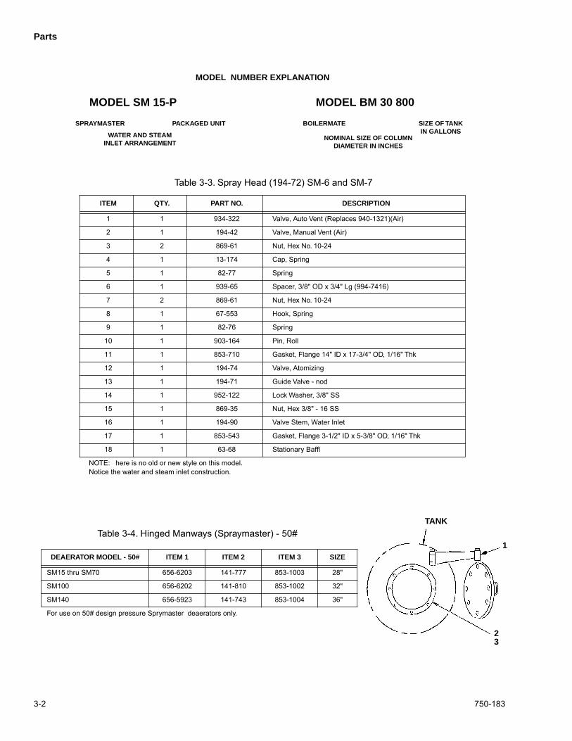
MODEL SM 15-P MODEL BM 30 800
SPRAYMASTER
WATER AND STEAMINLET ARRANGEMENT
PACKAGED UNIT BOILERMATE
NOMINAL SIZE OF COLUMNDIAMETER IN INCHES
SIZE OF TANKIN GALLONS
ITEM QTY. PART NO. DESCRIPTION
1 1 934-322 Valve, Auto Vent (Replaces 940-1321)(Air)
2 1 194-42 Valve, Manual Vent (Air)
3 2 869-61 Nut, Hex No. 10-24
4 1 13-174 Cap, Spring
5 1 82-77 Spring
6 1 939-65 Spacer, 3/8" OD x 3/4" Lg (994-7416)
7 2 869-61 Nut, Hex No. 10-24
8 1 67-553 Hook, Spring
9 1 82-76 Spring
10 1 903-164 Pin, Roll
11 1 853-710 Gasket, Flange 14" ID x 17-3/4" OD, 1/16" Thk
12 1 194-74 Valve, Atomizing
13 1 194-71 Guide Valve - nod
14 1 952-122 Lock Washer, 3/8" SS
15 1 869-35 Nut, Hex 3/8" - 16 SS
16 1 194-90 Valve Stem, Water Inlet
17 1 853-543 Gasket, Flange 3-1/2" ID x 5-3/8" OD, 1/16" Thk
18 1 63-68 Stationary Baffl
NOTE: here is no old or new style on this model. Notice the water and steam inlet construction.
Table 3-3. Spray Head (194-72) SM-6 and SM-7
DEAERATOR MODEL - 50# ITEM 1 ITEM 2 ITEM 3 SIZE
SM15 thru SM70 656-6203 141-777 853-1003 28"
SM100 656-6202 141-810 853-1002 32"
SM140 656-5923 141-743 853-1004 36"
For use on 50# design pressure Sprymaster deaerators only.
Table 3-4. Hinged Manways (Spraymaster) - 50#
MODEL NUMBER EXPLANATION
1
23
TANK
Parts
750-183 3-3
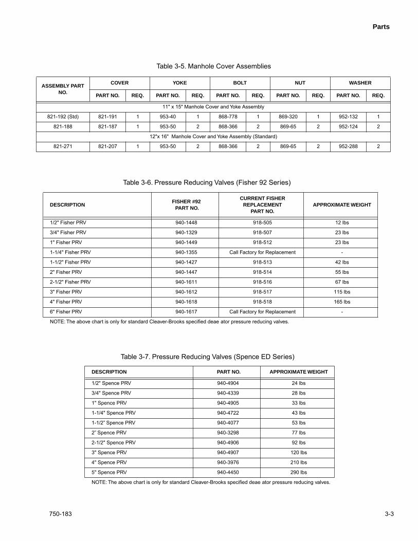
DESCRIPTIONFISHER #92 PART NO.
CURRENT FISHER REPLACEMENT
PART NO.APPROXIMATE WEIGHT
1/2" Fisher PRV 940-1448 918-505 12 lbs
3/4" Fisher PRV 940-1329 918-507 23 lbs
1" Fisher PRV 940-1449 918-512 23 lbs
1-1/4" Fisher PRV 940-1355 Call Factory for Replacement -
1-1/2" Fisher PRV 940-1427 918-513 42 lbs
2" Fisher PRV 940-1447 918-514 55 lbs
2-1/2" Fisher PRV 940-1611 918-516 67 lbs
3" Fisher PRV 940-1612 918-517 115 lbs
4" Fisher PRV 940-1618 918-518 165 lbs
6" Fisher PRV 940-1617 Call Factory for Replacement -
NOTE: The above chart is only for standard Cleaver-Brooks specified deae ator pressure reducing valves.
Table 3-6. Pressure Reducing Valves (Fisher 92 Series)
ASSEMBLY PART NO.
COVER YOKE BOLT NUT WASHER
PART NO. REQ. PART NO. REQ. PART NO. REQ. PART NO. REQ. PART NO. REQ.
11" x 15" Manhole Cover and Yoke Assembly
821-192 (Std) 821-191 1 953-40 1 868-778 1 869-320 1 952-132 1
821-188 821-187 1 953-50 2 868-366 2 869-65 2 952-124 2
12"x 16" Manhole Cover and Yoke Assembly (Standard)
821-271 821-207 1 953-50 2 868-366 2 869-65 2 952-288 2
Table 3-5. Manhole Cover Assemblies
DESCRIPTION PART NO. APPROXIMATE WEIGHT
1/2" Spence PRV 940-4904 24 lbs
3/4" Spence PRV 940-4339 28 lbs
1" Spence PRV 940-4905 33 lbs
1-1/4" Spence PRV 940-4722 43 lbs
1-1/2” Spence PRV 940-4077 53 lbs
2” Spence PRV 940-3298 77 lbs
2-1/2" Spence PRV 940-4906 92 lbs
3" Spence PRV 940-4907 120 lbs
4" Spence PRV 940-3976 210 lbs
5" Spence PRV 940-4450 290 lbs
NOTE: The above chart is only for standard Cleaver-Brooks specified deae ator pressure reducing valves.
Table 3-7. Pressure Reducing Valves (Spence ED Series)
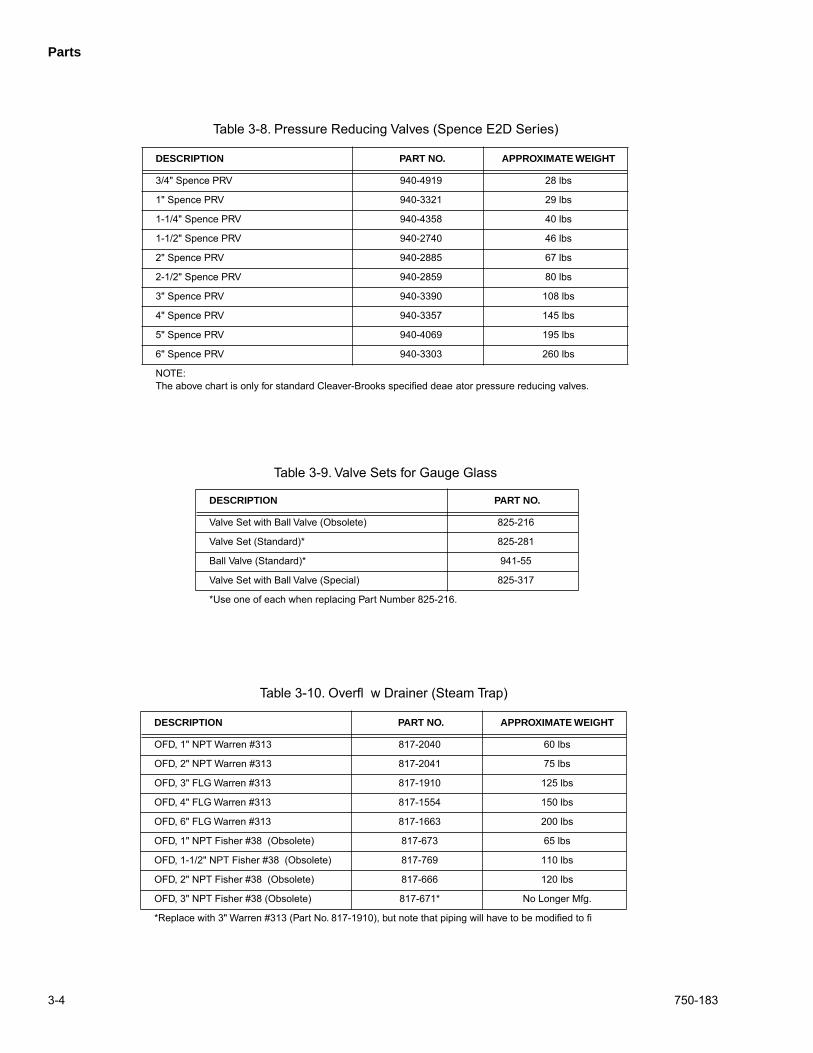
Parts
3-4 750-183
DESCRIPTION PART NO. APPROXIMATE WEIGHT
3/4" Spence PRV 940-4919 28 lbs
1" Spence PRV 940-3321 29 lbs
1-1/4" Spence PRV 940-4358 40 lbs
1-1/2" Spence PRV 940-2740 46 lbs
2" Spence PRV 940-2885 67 lbs
2-1/2" Spence PRV 940-2859 80 lbs
3" Spence PRV 940-3390 108 lbs
4" Spence PRV 940-3357 145 lbs
5" Spence PRV 940-4069 195 lbs
6" Spence PRV 940-3303 260 lbs
NOTE:The above chart is only for standard Cleaver-Brooks specified deae ator pressure reducing valves.
Table 3-8. Pressure Reducing Valves (Spence E2D Series)
DESCRIPTION PART NO.
Valve Set with Ball Valve (Obsolete) 825-216
Valve Set (Standard)* 825-281
Ball Valve (Standard)* 941-55
Valve Set with Ball Valve (Special) 825-317
*Use one of each when replacing Part Number 825-216.
Table 3-9. Valve Sets for Gauge Glass
DESCRIPTION PART NO. APPROXIMATE WEIGHT
OFD, 1" NPT Warren #313 817-2040 60 lbs
OFD, 2" NPT Warren #313 817-2041 75 lbs
OFD, 3" FLG Warren #313 817-1910 125 lbs
OFD, 4" FLG Warren #313 817-1554 150 lbs
OFD, 6" FLG Warren #313 817-1663 200 lbs
OFD, 1" NPT Fisher #38 (Obsolete) 817-673 65 lbs
OFD, 1-1/2" NPT Fisher #38 (Obsolete) 817-769 110 lbs
OFD, 2" NPT Fisher #38 (Obsolete) 817-666 120 lbs
OFD, 3" NPT Fisher #38 (Obsolete) 817-671* No Longer Mfg.
*Replace with 3" Warren #313 (Part No. 817-1910), but note that piping will have to be modified to fi
Table 3-10. Overfl w Drainer (Steam Trap)
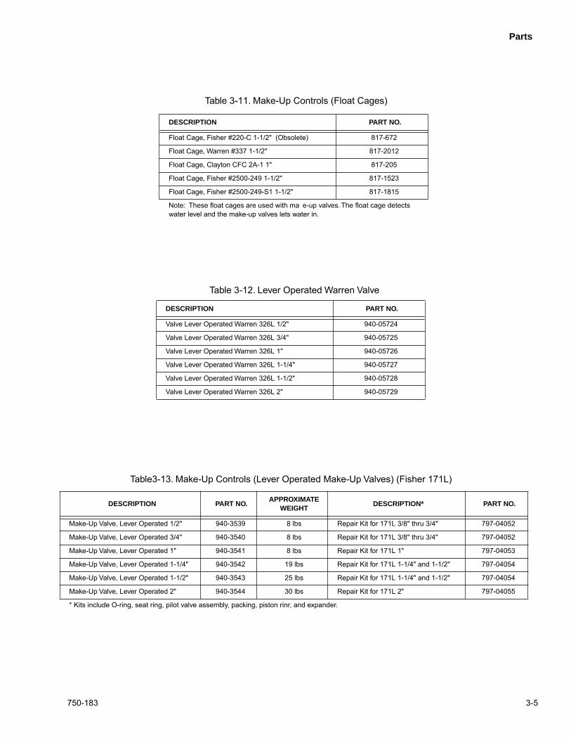
Parts
750-183 3-5
DESCRIPTION PART NO.
Float Cage, Fisher #220-C 1-1/2" (Obsolete) 817-672
Float Cage, Warren #337 1-1/2" 817-2012
Float Cage, Clayton CFC 2A-1 1" 817-205
Float Cage, Fisher #2500-249 1-1/2" 817-1523
Float Cage, Fisher #2500-249-S1 1-1/2" 817-1815
Note: These float cages are used with ma e-up valves. The float cage detectswater level and the make-up valves lets water in.
Table 3-11. Make-Up Controls (Float Cages)
DESCRIPTION PART NO.APPROXIMATE
WEIGHTDESCRIPTION* PART NO.
Make-Up Valve, Lever Operated 1/2" 940-3539 8 lbs Repair Kit for 171L 3/8" thru 3/4" 797-04052
Make-Up Valve, Lever Operated 3/4" 940-3540 8 lbs Repair Kit for 171L 3/8" thru 3/4" 797-04052
Make-Up Valve, Lever Operated 1" 940-3541 8 lbs Repair Kit for 171L 1" 797-04053
Make-Up Valve, Lever Operated 1-1/4" 940-3542 19 lbs Repair Kit for 171L 1-1/4" and 1-1/2" 797-04054
Make-Up Valve, Lever Operated 1-1/2" 940-3543 25 lbs Repair Kit for 171L 1-1/4" and 1-1/2" 797-04054
Make-Up Valve, Lever Operated 2" 940-3544 30 lbs Repair Kit for 171L 2" 797-04055
* Kits include O-ring, seat ring, pilot valve assembly, packing, piston rinr, and expander.
Table3-13. Make-Up Controls (Lever Operated Make-Up Valves) (Fisher 171L)
DESCRIPTION PART NO.
Valve Lever Operated Warren 326L 1/2" 940-05724
Valve Lever Operated Warren 326L 3/4" 940-05725
Valve Lever Operated Warren 326L 1" 940-05726
Valve Lever Operated Warren 326L 1-1/4" 940-05727
Valve Lever Operated Warren 326L 1-1/2" 940-05728
Valve Lever Operated Warren 326L 2" 940-05729
Table 3-12. Lever Operated Warren Valve
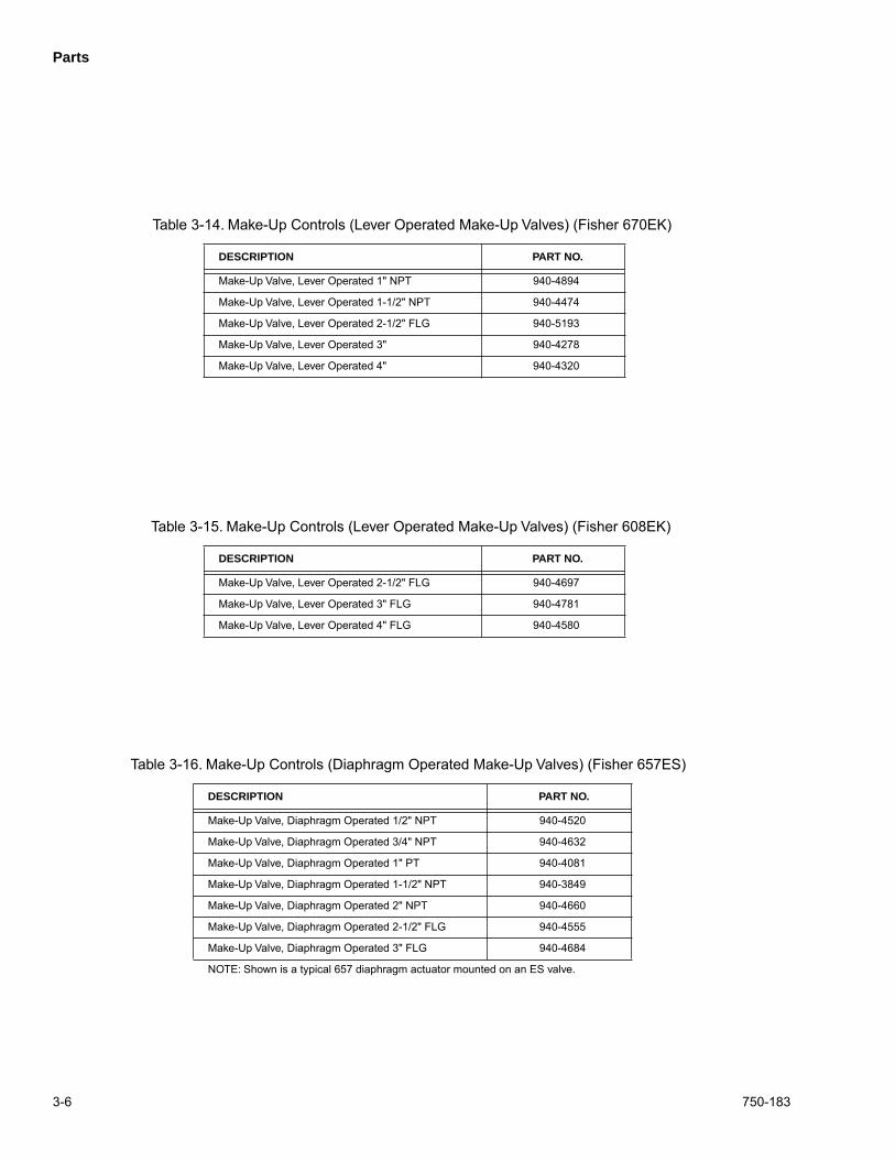
Parts
3-6 750-183
DESCRIPTION PART NO.
Make-Up Valve, Diaphragm Operated 1/2" NPT 940-4520
Make-Up Valve, Diaphragm Operated 3/4" NPT 940-4632
Make-Up Valve, Diaphragm Operated 1" PT 940-4081
Make-Up Valve, Diaphragm Operated 1-1/2" NPT 940-3849
Make-Up Valve, Diaphragm Operated 2" NPT 940-4660
Make-Up Valve, Diaphragm Operated 2-1/2" FLG 940-4555
Make-Up Valve, Diaphragm Operated 3" FLG 940-4684
NOTE: Shown is a typical 657 diaphragm actuator mounted on an ES valve.
Table 3-16. Make-Up Controls (Diaphragm Operated Make-Up Valves) (Fisher 657ES)
DESCRIPTION PART NO.
Make-Up Valve, Lever Operated 2-1/2" FLG 940-4697
Make-Up Valve, Lever Operated 3" FLG 940-4781
Make-Up Valve, Lever Operated 4" FLG 940-4580
Table 3-15. Make-Up Controls (Lever Operated Make-Up Valves) (Fisher 608EK)
DESCRIPTION PART NO.
Make-Up Valve, Lever Operated 1" NPT 940-4894
Make-Up Valve, Lever Operated 1-1/2" NPT 940-4474
Make-Up Valve, Lever Operated 2-1/2" FLG 940-5193
Make-Up Valve, Lever Operated 3" 940-4278
Make-Up Valve, Lever Operated 4" 940-4320
Table 3-14. Make-Up Controls (Lever Operated Make-Up Valves) (Fisher 670EK)
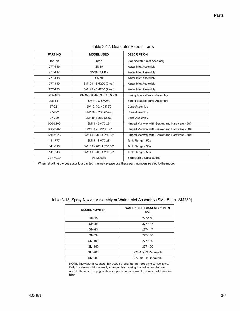
Parts
750-183 3-7
MODEL NUMBER WATER INLET ASSEMBLY PART
NO.
SM-15 277-116
SM-30 277-117
SM-45 277-117
SM-70 277-118
SM-100 277-119
SM-140 277-120
SM-200 277-119 (2 Required)
SM-280 277-120 (2 Required)
NOTE: The water inlet assembly does not change from old style to new style. Only the steam inlet assembly changed from spring loaded to counter bal-anced. The next fi e pages shows a parts break down of the water inlet assem-blies.
T
able 3-18. Spray Nozzle Assembly or Water Inlet Assembly (SM-15 thru SM280)
PART NO. MODEL USED DESCRIPTION
194-72 SM7 Steam/Water Inlet Assembly
277-116 SM15 Water Inlet Assembly
277-117 SM30 - SM45 Water Inlet Assembly
277-118 SM70 Water Inlet Assembly
277-119 SM100 - SM200 (2 ea.) Water Inlet Assembly
277-120 SM140 - SM280 (2 ea.) Water Inlet Assembly
295-109 SM15, 30, 45, 70, 100 & 200 Spring Loaded Valve Assembly
295-111 SM140 & SM280 Spring Loaded Valve Assembly
97-221 SM15, 30, 45 & 70 Cone Assembly
97-222 SM100 & 200 (2 ea.) Cone Assembly
97-239 SM140 & 280 (2 ea.) Cone Assembly
656-6203 SM15 - SM70 28" Hinged Manway with Gasket and Hardware - 50#
656-6202 SM100 - SM200 32" Hinged Manway with Gasket and Hardware - 50#
656-5923 SM140 - 200 & 280 36" Hinged Manway with Gasket and Hardware - 50#
141-777 SM15 - SM70 28" Tank Flange - 50#
141-810 SM100 - 200 & 280 32" Tank Flange - 50#
141-743 SM140 - 200 & 280 36" Tank Flange - 50#
797-4039 All Models Engineering Calculations
When retrofiting the deae ator to a davited manway, please use these part numbers related to the model.
Table 3-17. Deaerator Retrofit arts
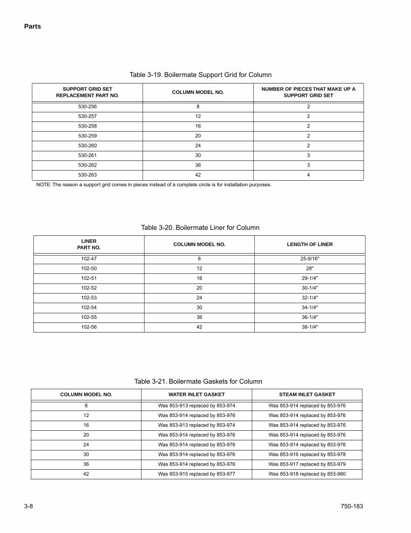
Parts
3-8 750-183
LINERPART NO.
COLUMN MODEL NO. LENGTH OF LINER
102-47 8 25-9/16"
102-50 12 28"
102-51 16 29-1/4"
102-52 20 30-1/4"
102-53 24 32-1/4"
102-54 30 34-1/4"
102-55 36 36-1/4"
102-56 42 38-1/4"
Table 3-20. Boilermate Liner for Column
COLUMN MODEL NO. WATER INLET GASKET STEAM INLET GASKET
8 Was 853-913 replaced by 853-974 Was 853-914 replaced by 853-976
12 Was 853-914 replaced by 853-976 Was 853-914 replaced by 853-976
16 Was 853-913 replaced by 853-974 Was 853-914 replaced by 853-976
20 Was 853-914 replaced by 853-976 Was 853-914 replaced by 853-976
24 Was 853-914 replaced by 853-976 Was 853-914 replaced by 853-976
30 Was 853-914 replaced by 853-976 Was 853-916 replaced by 853-978
36 Was 853-914 replaced by 853-976 Was 853-917 replaced by 853-979
42 Was 853-915 replaced by 853-977 Was 853-918 replaced by 853-980
Table 3-21. Boilermate Gaskets for Column
SUPPORT GRID SETREPLACEMENT PART NO.
COLUMN MODEL NO.NUMBER OF PIECES THAT MAKE UP A
SUPPORT GRID SET
530-256 8 2
530-257 12 2
530-258 16 2
530-259 20 2
530-260 24 2
530-261 30 3
530-262 36 3
530-263 42 4
NOTE: The reason a support grid comes in pieces instead of a complete circle is for installation purposes.
Table 3-19. Boilermate Support Grid for Column
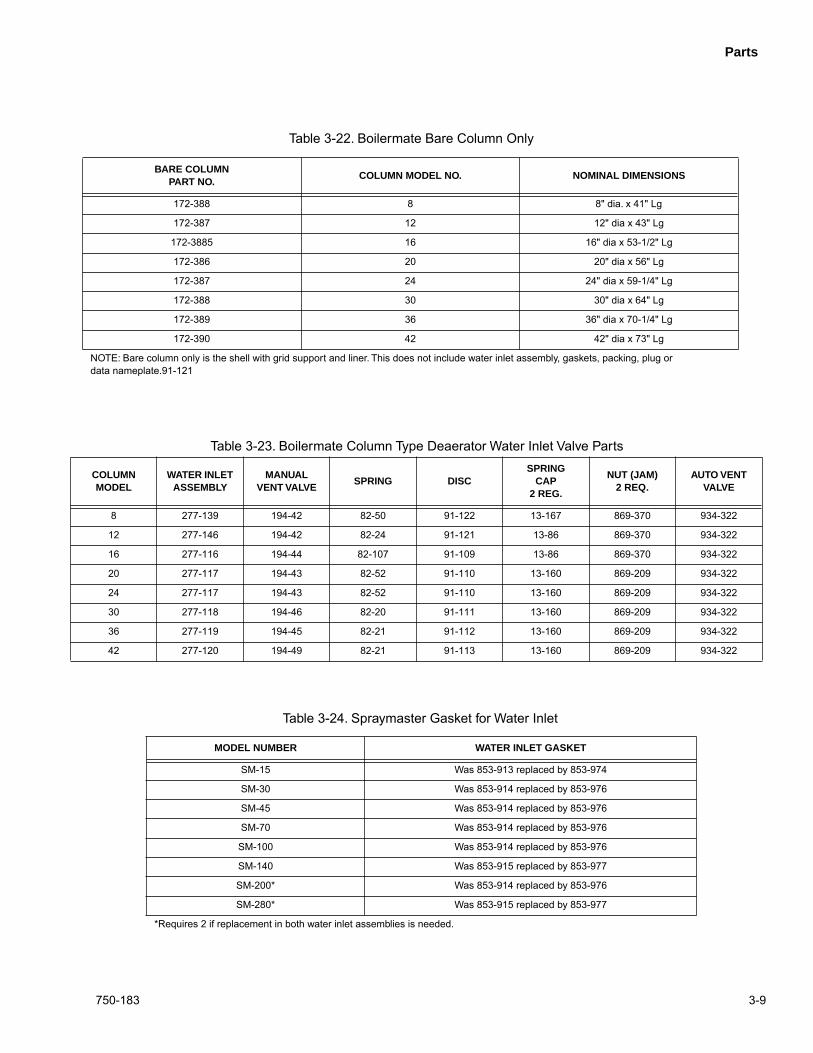
Parts
750-183 3-9
COLUMN MODEL
WATER INLET ASSEMBLY
MANUAL VENT VALVE
SPRING DISCSPRING
CAP 2 REG.
NUT (JAM)2 REQ.
AUTO VENT VALVE
8 277-139 194-42 82-50 91-122 13-167 869-370 934-322
12 277-146 194-42 82-24 91-121 13-86 869-370 934-322
16 277-116 194-44 82-107 91-109 13-86 869-370 934-322
20 277-117 194-43 82-52 91-110 13-160 869-209 934-322
24 277-117 194-43 82-52 91-110 13-160 869-209 934-322
30 277-118 194-46 82-20 91-111 13-160 869-209 934-322
36 277-119 194-45 82-21 91-112 13-160 869-209 934-322
42 277-120 194-49 82-21 91-113 13-160 869-209 934-322
Table 3-23. Boilermate Column Type Deaerator Water Inlet Valve Parts
MODEL NUMBER WATER INLET GASKET
SM-15 Was 853-913 replaced by 853-974
SM-30 Was 853-914 replaced by 853-976
SM-45 Was 853-914 replaced by 853-976
SM-70 Was 853-914 replaced by 853-976
SM-100 Was 853-914 replaced by 853-976
SM-140 Was 853-915 replaced by 853-977
SM-200* Was 853-914 replaced by 853-976
SM-280* Was 853-915 replaced by 853-977
*Requires 2 if replacement in both water inlet assemblies is needed.
Table 3-24. Spraymaster Gasket for Water Inlet
BARE COLUMNPART NO.
COLUMN MODEL NO. NOMINAL DIMENSIONS
172-388 8 8" dia. x 41" Lg
172-387 12 12" dia x 43" Lg
172-3885 16 16" dia x 53-1/2" Lg
172-386 20 20" dia x 56" Lg
172-387 24 24" dia x 59-1/4" Lg
172-388 30 30" dia x 64" Lg
172-389 36 36" dia x 70-1/4" Lg
172-390 42 42" dia x 73" Lg
NOTE: Bare column only is the shell with grid support and liner. This does not include water inlet assembly, gaskets, packing, plug or data nameplate.91-121
Table 3-22. Boilermate Bare Column Only

Parts
3-10 750-183
NOTES

NOTES