747e, Driescher - Indoor Vacuum Circuit-Breaker · Design and principle of operation of the vacuum...
12
24kV KUF V12- DRIESCHER - Indoor Vacuum Circuit-Breaker • Rated voltage 12 kV up to 38,5 kV • Rated current 630 A up to 2500 A 747 ELEKTROTECHNISCHE WERKE FRITZ DRIESCHER & SÖHNE GMBH D-85366 MOOSBURG • TEL. +49 87 61 6 81-0 • FAX +49 87 61 68 12 30 http://www.driescher.com [email protected]
Transcript of 747e, Driescher - Indoor Vacuum Circuit-Breaker · Design and principle of operation of the vacuum...

24kV
KU
F
V12-
DRIESCHER - Indoor
Vacuum Circuit-Breaker
• Rated voltage
12 kV up to 38,5 kV
• Rated current
630 A up to 2500 A
747
ELEKTROTECHNISCHE WERKEFRITZ DRIESCHER & SÖHNE GMBHD-85366 MOOSBURG • TEL. +49 87 61 6 81-0 • FAX +49 87 61 68 12 30http://www.driescher.com [email protected]

2
from 0 to 100 km/hin 0,03 seconds
DRIESCHER - Indoor Vacuum Circuit-Breaker
747
Category for capacitive current breaking C2Category for mechanical switching cycles M2
Rated voltage 12 kV 24 kV * 36 kV ** 38,5 kV
Rated short-time circuit current 20 kA 25 kA 31,5 kA 40 kA 20 kA 25 kA 31,5 kA 20 kA 31,5 kA 20 kA
Rated current
630 A
1250 A
1600 A
2000 A
2500 A
* this type with rated voltage 24 kV, was tested with a test voltage of 25 kV (On/Off test).** this type with rated voltage 36kV, was tested with a test voltage of 38,5 kV (On/Off test).

3
Operating conditions
The breakers are designed for normal operating con-
ditions in compliance with EN 62271-1, class „minus 5
indoors“. A reliable operation is still guaranteed at
minus temperatures of -15°.
The maximum ambient temperature is 40°C; the
mean value over 24 hours is max. 35°C. The values
on insulation strength are - corresponding to DIN
VDE 0671 Part 1 - related to sea level.
For installations at altitudes of up to 1000 m any
reduction in insulation caused by the reduced insula-
ting property of the air is insignificant and can be
ignored. For installation at altitudes > 1000 m it is
necessary to correct the values given for the rated
power-frequency withstand voltage and the rated
impulse withstand voltage (e.g. the insulating pro-
perty of the clearance at an altitude of 2000 m above
sea level is reduced by the factor 0,8).
The new DRIESCHER vacuum circuit-breaker is a
technological development of the well- proven vacu-
um circuit-breaker series 746.
These three-pole indoor circuit-breakers are desi-
gned for rated voltages of 12 kV up to 38,5 kV and
rated currents of 630 A up to 2500 A.
All specified circuit-breakers are delivered for front
panel installation.
General
Maintenance
These new DRIESCHER circuit-breakers boast extre-
mely low-maintenance. We recommend an visual ins-
pection and occasional cleaning of the insulating
parts. It is only necessary to lubricate the operating
mechanism.
DRIESCHER - Indoor Vacuum Circuit-Breaker
according to EN 62271-100
• 2 Overview
• 3 General, operating conditions, maintenance
• 4 Design and principle of operation of the circuit-breaker
• 5 Schematic diagram of the design
• 6 Technical data, type designation
• 7 Schematic diagram of release mechanism, motor-operated mechanism
• 8 Vacuum circuit-breaker; Ur 12 kV
• 9 Vacuum circuit-breaker; Ur 24 kV
• 10 Vacuum circuit-breaker; Ur 36 kV and 38,5 kV
• 11 Vacuum circuit-breaker V36-2500-31,5 KUF
• 12 Sample wiring diagram, accessories
747

4
Design and principle of operation of the vacuum circuit-breaker
The new DRIESCHER vacuum circuit-breaker is a
technical further development of our well-proven
vacuum circuit-breaker series 746.
This vacuum circuit-breaker is made up of the fol-
lowing five (refer also to page 5) sub-assemblies
which are coordinated with maximum precision:
Via operating mechnism the coil-spring energy
storage mechanism is manually or electrically char-
ged. Should the supply voltage fail, the coil-spring
energy storage mechanism can be charged via the
operating shaft using a crank.
Feature:
- an overload blocking in the operating mechanism
prevents any overloading of the energy storage
mechanism.
The coil-spring energy storage mechnism com-
prises three coil springs and an end position dam-
ping. This stores the energy (display), precisely
controls the energy transmission and permits con-
stant operating speeds.
Feature:
- The energy is stored for 3 switching operations
- The adjusted end position damping permits an
optimal switching operation. The mechanism is
therefore extremely low in wear, low in main-
tenance, and has a long service life.
Via the switching module it is possible to operate
the circuit-breaker manually by pressing the push-but-
tons or it can be operated electrically (release mecha-
nism). The motor of the operating mechanism imme-
diately recharges the coil-spring energy storage
mechanism after operation. In addition to the release
mechanisms the switching module also includes the
locking mechanisms.
Feature:
- The last possible switching operation is always and
OFF switching operation
- For further electrical operations a second OFF
release can be installed
The electrical components with their displays
(operations counter, switch position) operate the cir-
cuit-breaker depending on the wiring diagram (e.g.
auto reclosing). The 70-pin female connector (11) is
positioned on the top of the breaker frame.
The male connector (10) ist part of the delivery or
part of the corresponding panel.
The operating shaft assembled in the breaker
frame transmits the operating energy via insula-
ting bars (8) to the vacuum interrupters.
Advantage of the breaker frame:
- compact design possible
- very lightweight and stable
The high quality vaccum tubes are housed in moul-
ded parts of Duroplast insulating material (9).
The current in the breaker pole flows from the upper
terminal (1) to the fixed contact (2) of the vacuum
tube.
The laminated contact ribbon (4) is screwed to the
moving contact (3) of the vacuum tube. The spring
(5) provides the required contact pressure and com-
pensates the permissible contact burn (M) during
the entire service life. The burn of the contacts in the
vacuum tube can be monitored using the "M" mark.
This can be carried out without necessitating dis-
mantling. The pressure welded end of the contact rib-
bon forms the lower pole contact surface (7) which is
supported by the contact arm (6).
Advantage:
- the vacuum tubes are protected against
extreme ambient conditions and damage
- the entire pole can be removed as one piece
Summary:
The sub-assemblies and their optimal arrangement
have made it possible to provide an extremely
compact design.
This circuit-breaker is therefore extremely fle-
xible in its application and meets all customer
requirements to the full.
This new, optimised mechanical design also per-
mits a minimum amount of maintenance and gua-
rantees an extremely long service life.
1
5
2
3
4
747
5
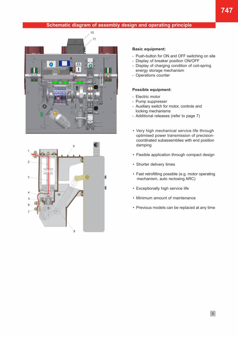
Schematic diagram of assembly design and operating principle
• Very high mechanical service life through
optimised power transmission of precision-
coordinated subassemblies with end position
damping
• Flexible application through compact design
• Shorter delivery times
• Fast retrofitting possible (e.g. motor operating
mechanism, auto reclosing ARC)
• Exceptionally high service life
• Minimum amount of maintenance
• Previous models can be replaced at any time
Basic equipment:
- Push-button for ON and OFF switching on site
- Display of breaker position ON/OFF
- Display of charging condition of coil-spring
energy storage mechanism
- Operations counter
Possible equipment:
- Electric motor
- Pump suppresser
- Auxiliary switch for motor, controls and
locking mechanisms
- Additional releases (refer to page 7)1
2
34
5
11
10
747

6
Technical data
Type designation
Examples: V12-630-20 F-BK V24-1250-25 KUF
Vacuum circuit breaker V V
Rated current (12 kV or 24 kV) 12 24
Rated voltage (630 A or 1250 A) 630 1250
Rated short-circuit breaking current (kA) 20 25
Design for front-panel mounting (e.g. on switchgear truck) F
- with coil-spring energy storage mechanism BK
Design for front-panel mounting (e.g. on switchgear truck) F
- with coil-spring energy storage mechanism and suitable for auto-reclosing (ARC) KU
Types:
V....BK-EA with coil spring stored energy mechanism, front-panel mounting for manual operation, ON and OFF
V....F-BK with coil spring stored energy mechanism, front-panel mounting for manual operation
V....KUF with coil spring stored energy mechanism and suitable for automatic reclosing (ARC),
front-panel mounting for motorised operation
O - 0,3s - CO - 15s - CO for motorised actuator
O - 3 min - CO for manual actuator
Rated switching action sequence:
747
Ur
fr
Ir
Ik
tk
Ip
Up
Ud
ms
ms
ms
%
Isc
Ic
12 kV
50 Hz
630 ... 2500 A8)
20 ... 40 kA
3 s
50 ... 100 kA
75 kV
28 kV
65
<17
60
23
20 ... 40 kA
50 ... 100 kA
25 A
100
10.000
C2
M2
S1
24 kV
50 Hz
630 ... 2500 A8)
20 ... 31,5 kA
3 s
50 ... 80 kA
125 kV
50 kV
65
<17
65
23
20 ... 31,5 kA
50 ... 80 kA
31,5 A
100
10.000
C2
M2
S1
36 kV
50 Hz
630 ... 2500 A8)
20 ... 31,5 kA
3 s
50 ... 80 kA
170 kV
70 kV
65
<17
70
23
20 ... 31,5 kA
50 ... 80 kA
50 A
100
10.000
C2
M2
S1
38,5 kV
50 Hz
630 ...1250 A
20 kA
3 s
50 kA
180 kV
80 kV
65
<17
70
23
20 kA
50 kA
50 A
100
10.000
C2
M2
S1
8) for application in metal-encapsulated panels, are additional ventilation and cooling measures necessary, from 1600 A
Rated voltage
Rated frequency
Rated current
Rated short-time current
Rated short-circuit duration
Rated peak withstand current
Rated impulse withstand voltage
Rated power frequency withstand voltage
Closing time approx.
Arcing time
Opening time approx.
Direct current component
Rated short circuit breaking current
Rated short circuit making current
Rated cable charging breaking current
Operating cycles
- of the vacuum tube at rated short circuit breaking current
- of the breaker mechanism
Cable charging switching class
Mechanical life
Application class

7
Motor-operated mechanism
Motors can optionally be delivered for AC or DC
systems.
The motors operate in short-time duty (S2).
The supply voltage should not deviate from the rated
supply voltage by more than -15% to +10%.
Motor protection switchCurrent input
(A)
2,2
1,2
8,8
4,5
4,5
2,2
1,3
Consumption
(VA)
242
276
Consumption
(W)
211
216
270
242
286
Charging time
(s)
8,2
7,8
9,3
7,3
5,7
8,2
8,8
..A
2,5 - 4
1 - 1,6
6,3 - 10
4 - 6,3
4 - 6,3
2,5 - 4
1 - 1,6
(A)
2,5
1
9
4,4
4,6
3
1,1
Motor voltage
(V)
110 AC
230 AC
24 DC
48 DC
60 DC
110 DC
220 DC
Schematic diagram of release mechanism
ASA
ASA
ASA
ASA
ASA
ASA
RSA
RSA
RSA
RSA
RSA
WSA
WSA
WSA
0,5
1,0
5,0
12
24
48
60
110
220
24
48
60
110
220
-
-
-
-
-
-
-
100/110
230
-
-
100/110
-
230
-
-
-
-
-
-
-
772 03110
772 03220
-
-
772 05110
-
772 05220
772 06005
772 06010
772 06050
56
56
88
56
57
50
10
10
10
10
10
-
-
-
-
-
-
-
105
110
-
-
19,5
-
19,5
18
18
18
772 04012
772 04024
772 04048
772 04060
772 04110
772 04220
772 05024
772 05048
772 05060
772 05115
772 05225
-
-
-
Type Rated current
(A)
Rated voltage
(V)
AC operation DC operation
Rated voltage
(V)Consumption
(W)
Consumption
(VA)Part no.Part no.
• Shunt release
• Under-voltage release
• Transformer-operated release
Manual operation (only in type ASA and WSA)
Striker-pin arresting bolt
M 5 only in Type RSA
(remove for commissioning !)
747

8
V12-630-20 KUF
V12-630-20 KUF
V12-630-25 KUF
V12-630-25 KUF
V12-800-20 KUF
V12-800-20 KUF
V12-800-25 KUF
V12-1250-20 KUF
V12-1250-20 KUF
V12-1250-25 KUF
V12-1250-25 KUF
V12-1600-31,5 KUF
V12-2500-31,5 KUF
V12-2500-40-BK-EA
12 kV
12 kV
12 kV
12 kV
12 kV
12 kV
12 kV
12 kV
12 kV
12 kV
12 kV
12 kV
12 kV
12 kV
100
103
100
103
102
105
102
105
110
105
110
110
112
130
630 A
630 A
630 A
630 A
800 A
800 A
800 A
1250 A
1250 A
1250 A
1250 A
1600 A8)
2500 A8)
2500 A8)
103293-001
103294-001
094237-001
096848-001
103295-001
105151-001
097092-001
103296-001
103297-001
096849-001
096850-001
119267-001
104762-001
117081-001
Type
Rated
voltage
Pole distance
p (mm)
Weight
approx. (kg)Rated
current Drawing no.lH
20 kA
20 kA
25 kA
25 kA
20 kA
20 kA
25 kA
20 kA
20 kA
25 kA
25 kA
31,5 kA
31,5 kA
40 kA
25
25
25
25
25
25
25
29
29
29
29
38
38
36
1556)
210
1556)
210
1556)
210
1556)
1556)
210
1556)
210
2505)
2505)
2505)
464,5
464,5
464,5
464,5
464,5
464,5
464,5
470,5
470,5
470,5
470,5
482,5
482,5
477
747 0400x
747 1400x
747 0401x
747 1401x
747 0410x
747 1410x
747 0411x
747 0420x
747 1420x
747 0421x
747 1421x
747 2432x
747 9152x
747 2152x
460
550
460
550
460
550
460
460
550
460
550
620
620
620
Part no.4)
420
510
420
510
420
510
420
420
510
420
510
500
500
500
c
23
23
23
23
23
23
23
23
23
23
23
60
60
60
c d
Vacuum circuit-breaker Ur 12 kV
Rated short circuit
breaking current 1
The vacuum circuit-breakers of type KUF listed here are equipped with a motor actuator and are suitable for
auto-reclosing (ARC). All breakers are also available as type F-BK, manually operated circuit-breakers.
All types are also available as 1-pole design.
1) hexagon bolt M12x40 (from 1600 A; M12x50) with nut, washer and lock washer
2) threaded pin (fixed) with nut, washer and lock washer
3) for 1250 A two connecting bolts and one connectiing bar, from 1600 A two connecting bolts and two connecting bars!
4) the last digit of the part numbers indicates the respective motor voltage:
747 xxxx1 = 230 V AC
747 xxxx2 = 110 V AC
747 xxxx3 = 220 V DC
747 xxxx4 = 110 V DC
747 xxxx5 = 60 V DC
747 xxxx6 = 48 V DC
747 xxxx7 = 24 V DC
5) appropriate extra insulation is required
6) appropriate bar support is required
7) press-in nuts M12 at the top and bottom for mounting switchgear, refer also to c and c
8) for application in metal-encapsulated panels, are additional ventilation and cooling measures necessary1
Manual emer-
gency charging
of energy stora-
ge mechanism
Typeplate
Counter ON-OFF Display
ON
OFF
Display for number of
operations available
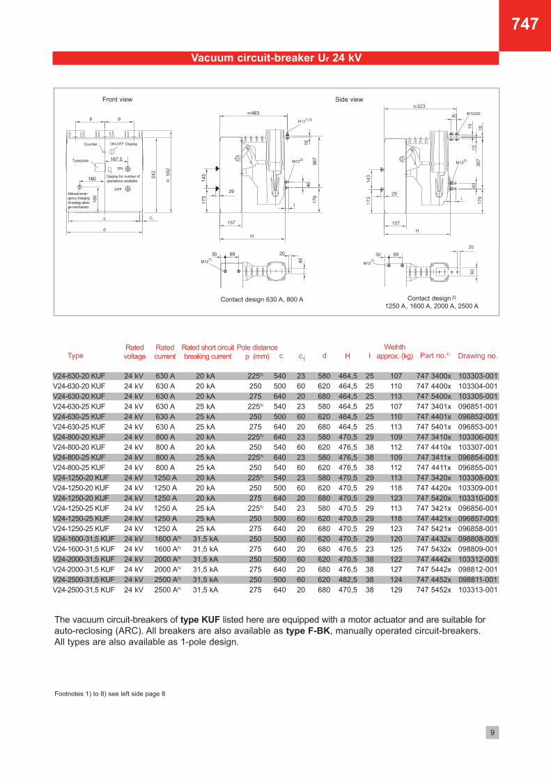
Front view Side view
Contact design 3)
1250 A, 1600 A, 2000 A, 2500 AContact design 630 A, 800 A
747
8)
8)
9
V24-630-20 KUF
V24-630-20 KUF
V24-630-20 KUF
V24-630-25 KUF
V24-630-25 KUF
V24-630-25 KUF
V24-800-20 KUF
V24-800-20 KUF
V24-800-25 KUF
V24-800-25 KUF
V24-1250-20 KUF
V24-1250-20 KUF
V24-1250-20 KUF
V24-1250-25 KUF
V24-1250-25 KUF
V24-1250-25 KUF
V24-1600-31,5 KUF
V24-1600-31,5 KUF
V24-2000-31,5 KUF
V24-2000-31,5 KUF
V24-2500-31,5 KUF
V24-2500-31,5 KUF
24 kV
24 kV
24 kV
24 kV
24 kV
24 kV
24 kV
24 kV
24 kV
24 kV
24 kV
24 kV
24 kV
24 kV
24 kV
24 kV
24 kV
24 kV
24 kV
24 kV
24 kV
24 kV
630 A
630 A
630 A
630 A
630 A
630 A
800 A
800 A
800 A
800 A
1250 A
1250 A
1250 A
1250 A
1250 A
1250 A
1600 A8)
1600 A8)
2000 A8)
2000 A8)
2500 A8)
2500 A8)
103303-001
103304-001
103305-001
096851-001
096852-001
096853-001
103306-001
103307-001
096854-001
096855-001
103308-001
103309-001
103310-001
096856-001
096857-001
096858-001
098808-001
098809-001
103312-001
098812-001
098811-001
103313-001
TypeRated
voltage
Rated short circuit
breaking current
Pole distance
p (mm)
Rated
current Drawing no.l
20 kA
20 kA
20 kA
25 kA
25 kA
25 kA
20 kA
20 kA
25 kA
25 kA
20 kA
20 kA
20 kA
25 kA
25 kA
25 kA
31,5 kA
31,5 kA
31,5 kA
31,5 kA
31,5 kA
31,5 kA
25
25
25
25
25
25
29
38
38
38
29
29
29
29
29
29
29
23
38
38
38
38
2255)
250
275
2255)
250
275
2255)
250
2255)
250
2255)
250
275
2255)
250
275
250
275
250
275
250
275
464,5
464,5
464,5
464,5
464,5
464,5
470,5
476,5
476,5
476,5
470,5
470,5
470,5
470,5
470,5
470,5
470,5
476,5
470,5
476,5
482,5
470,5
747 3400x
747 4400x
747 5400x
747 3401x
747 4401x
747 5401x
747 3410x
747 4410x
747 3411x
747 4411x
747 3420x
747 4420x
747 5420x
747 3421x
747 4421x
747 5421x
747 4432x
747 5432x
747 4442x
747 5442x
747 4452x
747 5452x
580
620
680
580
620
680
580
620
580
620
580
620
680
580
620
680
620
680
620
680
620
680
Part no.4)
540
500
640
540
500
640
640
540
640
540
540
500
640
540
500
640
500
640
500
640
500
640
c d H
23
60
20
23
60
20
23
60
23
60
23
60
20
23
60
20
60
20
60
20
60
20
c1
Vacuum circuit-breaker Ur 24 kV
Footnotes 1) to 8) see left side page 8
107
110
113
107
110
113
109
112
109
112
113
118
123
113
118
123
120
125
122
127
124
129
Weihth
approx. (kg)
The vacuum circuit-breakers of type KUF listed here are equipped with a motor actuator and are suitable for
auto-reclosing (ARC). All breakers are also available as type F-BK, manually operated circuit-breakers.
All types are also available as 1-pole design.
Manual emer-
gency charging
of energy stora-
ge mechanism
Typeplate
Counter ON-OFF Display
ON
OFF
Display for number of
operations available
Front view Side view
Contact design 3)
1250 A, 1600 A, 2000 A, 2500 AContact design 630 A, 800 A
747
10
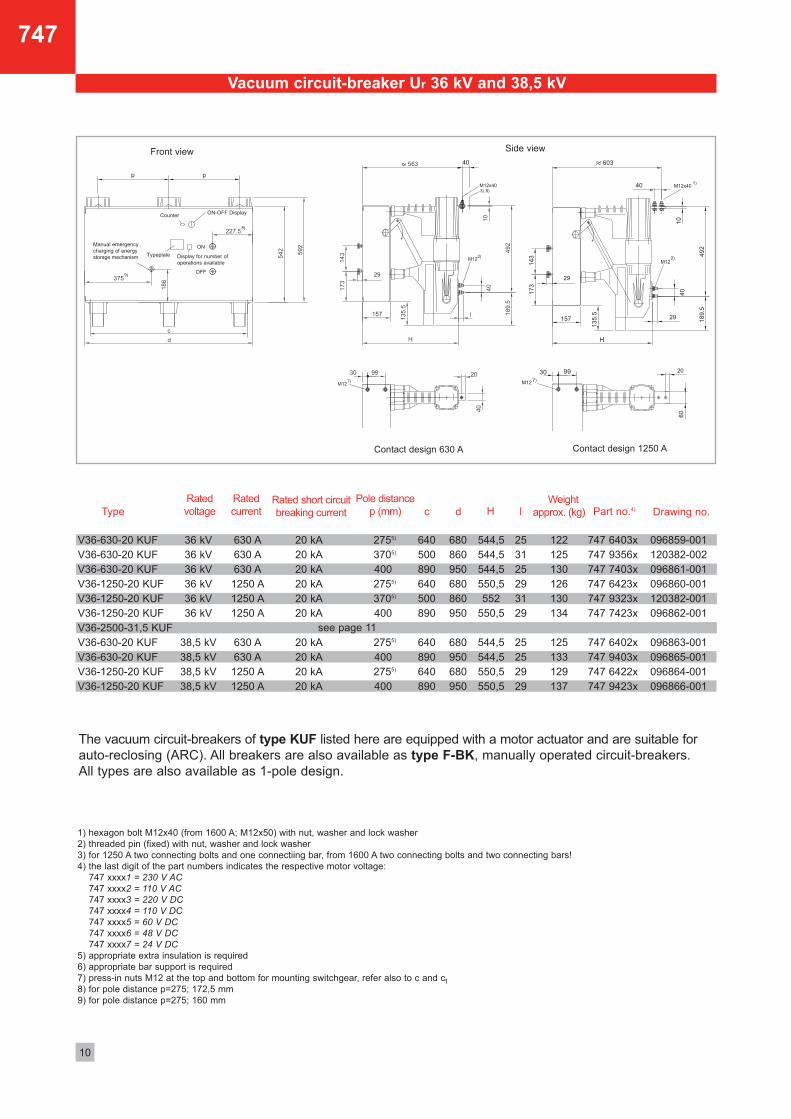
1) hexagon bolt M12x40 (from 1600 A; M12x50) with nut, washer and lock washer
2) threaded pin (fixed) with nut, washer and lock washer
3) for 1250 A two connecting bolts and one connectiing bar, from 1600 A two connecting bolts and two connecting bars!
4) the last digit of the part numbers indicates the respective motor voltage:
747 xxxx1 = 230 V AC
747 xxxx2 = 110 V AC
747 xxxx3 = 220 V DC
747 xxxx4 = 110 V DC
747 xxxx5 = 60 V DC
747 xxxx6 = 48 V DC
747 xxxx7 = 24 V DC
5) appropriate extra insulation is required
6) appropriate bar support is required
7) press-in nuts M12 at the top and bottom for mounting switchgear, refer also to c and c
8) for pole distance p=275; 172,5 mm
9) for pole distance p=275; 160 mm
1
Rated short circuit
breaking current
V36-630-20 KUF
V36-630-20 KUF
V36-630-20 KUF
V36-1250-20 KUF
V36-1250-20 KUF
V36-1250-20 KUF
V36-2500-31,5 KUF
V36-630-20 KUF
V36-630-20 KUF
V36-1250-20 KUF
V36-1250-20 KUF
36 kV
36 kV
36 kV
36 kV
36 kV
36 kV
38,5 kV
38,5 kV
38,5 kV
38,5 kV
630 A
630 A
630 A
1250 A
1250 A
1250 A
630 A
630 A
1250 A
1250 A
096859-001
120382-002
096861-001
096860-001
120382-001
096862-001
096863-001
096865-001
096864-001
096866-001
Type
Rated
voltage
Pole distance
p (mm)
Rated
current Drawing no.l
20 kA
20 kA
20 kA
20 kA
20 kA
20 kA
20 kA
20 kA
20 kA
20 kA
25
31
25
29
31
29
25
25
29
29
2755)
3705)
400
2755)
3705)
400
2755)
400
2755)
400
544,5
544,5
544,5
550,5
552
550,5
544,5
544,5
550,5
550,5
747 6403x
747 9356x
747 7403x
747 6423x
747 9323x
747 7423x
747 6402x
747 9403x
747 6422x
747 9423x
680
860
950
680
860
950
680
950
680
950
Part no.4)
640
500
890
640
500
890
640
890
640
890
c d
Vacuum circuit-breaker Ur 36 kV and 38,5 kV
H
122
125
130
126
130
134
125
133
129
137
Weight
approx. (kg)
Contact design 1250 AContact design 630 A
Front view Side view
Typeplate
OFF
ON
ON-OFF DisplayCounter
Display for number of
operations available
Manual emergency
charging of energy
storage mechanism
747
see page 11
The vacuum circuit-breakers of type KUF listed here are equipped with a motor actuator and are suitable for
auto-reclosing (ARC). All breakers are also available as type F-BK, manually operated circuit-breakers.
All types are also available as 1-pole design.
11
747
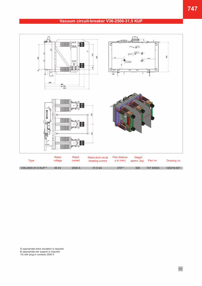
Vacuum circuit-breaker V36-2500-31,5 KUF
5) appropriate extra insulation is required
6) appropriate bar support is required
10) with plug-in contacts 2500 A
Rated short circuit
breaking current
V36-2500-31,5 KUF10) 36 kV 2500 A 120216-001
Type
Rated
voltage
Pole distance
p in (mm)
Rated
current Drawing no.
31,5 kA 3705,6) 747 93553
Part no.
300
Weight
approx. (kg)

Order No. 3-81707471 • 10-16
ELEKTROTECHNISCHE WERKEFRITZ DRIESCHER & SÖHNE GMBHD-85366 MOOSBURG • TEL. +49 87 61 6 81-0 • FAX +49 87 61 68 12 30http://www.driescher.com [email protected]
Our range of products includes:
Medium-voltage systems• Single-busbar and duplicate-busbar switchgear• Fixed mounting, withdrawable design and truck-type units• Compact switchgear assemblies• Customer-specific models• Industrial switchgear• Power factor correction and filter equipment
Medium-voltage switches• Indoor load-break switches, disconnectors, and earthing switches (single and triple pole)• Indoor circuit breakers (low oil content and vacuum)• Outdoor load-break switches, disconnectors, and earthing switches (single and triple pole)• Railway switches for power supply and catenary• High-voltage high-breaking-capacity fuses• Customer-specific switches
Low-voltage systems• Open-framework design• Enclosed switchgear (up to 6.300 A)• Motor Control Center (MCC)• Cable and fixed-station distribution cabinets
Low-voltage switches• Switch disconnectors• Switching strips and fuse blocks
Compact sub-station• Concrete construction• Container construction
Driving gear• Hand-operated and motor-operated mechanisms
for indoor and outdoor application
Accessories• For medium and low voltage• For station equipment• Insulators (0,5 kV - 38,5 kV)• Plastic and glass fibre-reinforced plastic screening
Service• Maintenance and Service of all switches and switchgear• Training courses and seminars• Thermography; Live-line working
STROM • SICHER • SCHALTEN
Dimensions, weights , diagrams and descriptions in the list are non-binding. Subject to change without notice.
747
The accessories for the vacuum circuit-breaker con-
sists of a emergeny hand-crank for the energy stora-
ge mechanism.
More accessories for the application in switchgears,
for e.g. withdrawable trucks with and without motor
actuator, auxiliary truck or service truck, can be find
in brochure 785, switchpanels in withdrawable
design Type WEL or E2K, E3K.
Accessories
Sample wiring diagram
Drawing no.
096793-001
096793-002
096793-003
096793-004
096793-005
Application
integral mounting 12, 24, 36 kV
integral mounting 12, 24, 36 kV
withdrawable-unit design range 300 mm
withdrawable-unit design range 200 mm
integral mounting 36 and 38,5 kV
A
50
210
410
310
100
B
184
344
544
444
234
Part no.
770 60113
770 60114
770 60115
770 60116
770 60117
����������������������
���� ����������������������
12.01.2010 Heindl
18.09.2006
��
LS4
Radlmaier 3D Zeichnunge 12.01.2010
FormatMaßstab 2:
Auftraggeber:
Maßstab 1:
Norm
Gepr.
Bearb.
Datum Name Art der Änderung
Entstanden aus:
Ersatz für:
Ersetzt durch:
Index
Kommisions Nr.:
Zeichnungs-Nr. Index
Blatt
Pos.
Diese Zeichnung ist unter
Vorbehalt aller Rechte
geschützt und darf weder
vervielfältigt noch Dritten,
insbesondere
Wettbewerbern zugänglich
gemacht werden.
Driescher Moosburg
85368 Moosburg / Isar
Fritz Driescher & Söhne GmbHElektrotechnische Werke
������������ !"����� ���# �$�%�&'(�
$��)� *���+����$��%� �096793 e
������
Änd.
Änd.
LS4-096793/2d
- -
Teile-Nr.2-77060114
OBJEKT ANZAHL TEILE-NR. BEZEICHNUNG BAUTEIL-NR.
1 1 2-61703520 Handkurbel 096793-B01-
2 1 2-63108080 Hülse 096794-001-
3 1 1-21289138 Spannstift ISO 8752 - 5x28 N01116-000-00
4 1 2-63108060 Distanzstück 096795-001-
5 1 1-21289136 Spannstift ISO 8752 - 5x24 A N00044-000-
210
130
344
26�
25�
�16,2
160
B
A
Sample