742/762 Control 255 and Performa Series Valves...
64
For Sales & Service questions please contact your dealer: Your local dealer is: 742/762 Control 255 and Performa Series Valves (263, 268, 268FA) Operation Manual
Transcript of 742/762 Control 255 and Performa Series Valves...
25
742/762 Control5 and Performa Series Valves
For Sales & Service questions please contact your dealer:
Your local dealer is:
(263, 268, 268FA)
Operation Manual

TABLE OF CONTENTS
LOGIX™ SERIES INSTALLER QUICK-START SHEET 3
MANUAL OVERVIEW 8
How To Use This Manual
EQUIPMENT INSTALLATION 9
General Warnings And Safety InformationPerformance Data SheetsValve FeaturesLocation SelectionWater Line ConnectionDrain Line ConnectionOverflow Line ConnectionRegenerant Line ConnectionElectrical ConnectionValve Camshaft
SYSTEM DISINFECTION 30
Disinfection Of Water Conditioners
DETERMINING IF YOU HAVE A 742 OR 762 CONTROL 32
GENERAL 700 SERIES INSTRUCTIONS 33
Display Icons 700 ControllerKeypad — ButtonsRegeneration Modes742/762 Series Initial Power-UpInitial Start-up Step-By-Step Instructions
PLACING CONDITIONER INTO OPERATION (turning on the water) 42
PROGRAMMING THE 700 FOR 5-CYCLE FILTER APPLICATIONS 45
Manganese Greensand Systems
742/762 SERIES ADVANCED PROGRAMMING 48
742/762 Level II Professional Programming 49
PARTS AND ACCESSORIES 52
255 Valve Exploded View255 Valve Parts ListPerforma Exploded ViewPerforma Parts ListLogix 700 Series Controllers Parts List
TROUBLESHOOTING 58
2 Rev J
QU
ICK
STA
RT
LOGIX™ SERIES INSTALLER QUICK-START SHEET
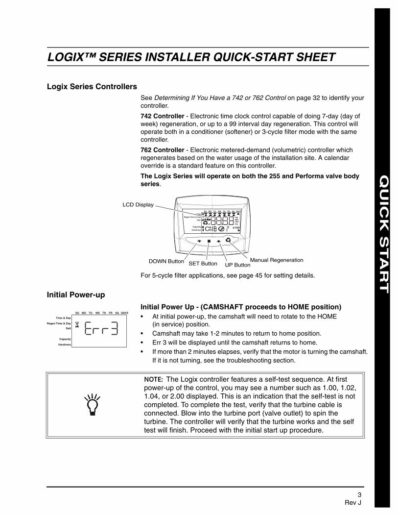
Logix Series ControllersSee Determining If You Have a 742 or 762 Control on page 32 to identify your controller.
742 Controller - Electronic time clock control capable of doing 7-day (day of week) regeneration, or up to a 99 interval day regeneration. This control will operate both in a conditioner (softener) or 3-cycle filter mode with the same controller.
762 Controller - Electronic metered-demand (volumetric) controller which regenerates based on the water usage of the installation site. A calendar override is a standard feature on this controller.
The Logix Series will operate on both the 255 and Performa valve body series.
For 5-cycle filter applications, see page 45 for setting details.
Initial Power-up
Initial Power Up - (CAMSHAFT proceeds to HOME position)• At initial power-up, the camshaft will need to rotate to the HOME
(in service) position.• Camshaft may take 1-2 minutes to return to home position.• Err 3 will be displayed until the camshaft returns to home.• If more than 2 minutes elapses, verify that the motor is turning the camshaft.
If it is not turning, see the troubleshooting section.
Time & Day
Regen Time & Day
Salt
SU MO TU WE TH FR SA DAYS
LBS
PMMIN
KG
x100x2
PHC
Capacity
Hardness
Manual RegenerationUP ButtonSET ButtonDOWN Button
LCD Display
Time & Day
Regen Time & Day
Salt
Capacity
Hardness
SU MO TU WE TH FR SA DAYS
NOTE: The Logix controller features a self-test sequence. At first power-up of the control, you may see a number such as 1.00, 1.02, 1.04, or 2.00 displayed. This is an indication that the self-test is not completed. To complete the test, verify that the turbine cable is connected. Blow into the turbine port (valve outlet) to spin the turbine. The controller will verify that the turbine works and the self test will finish. Proceed with the initial start up procedure.
3Rev J
QU
ICK
STA
RT
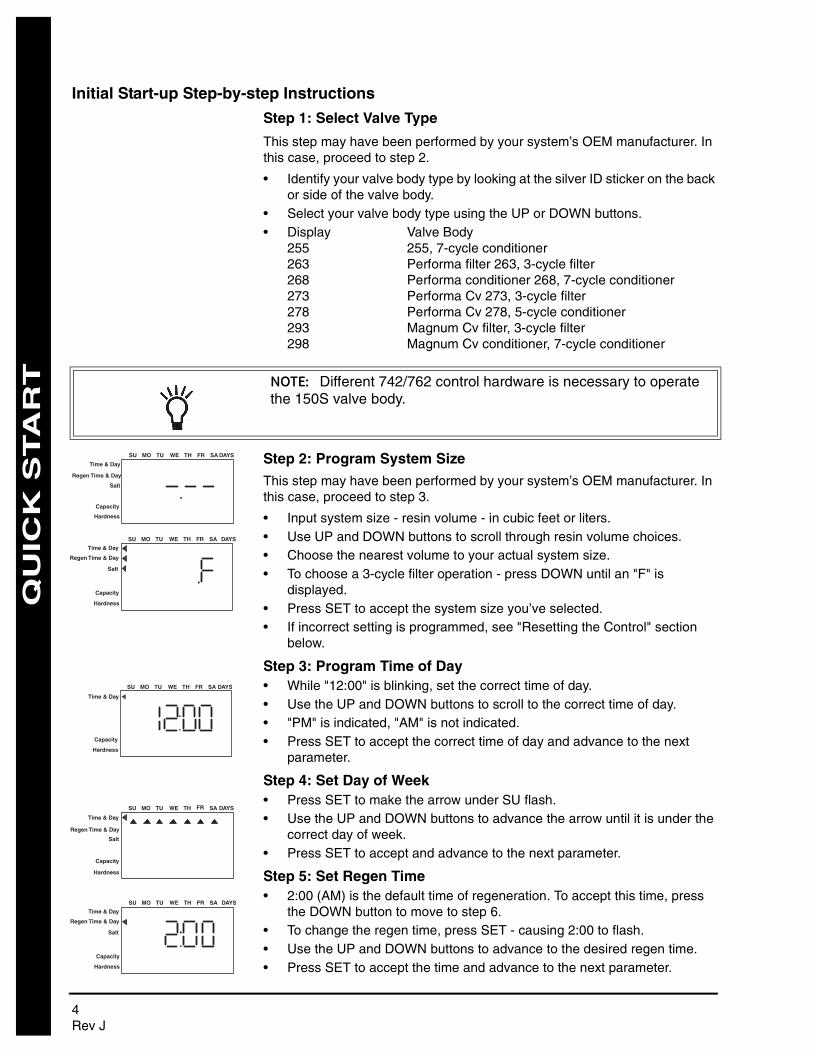
Initial Start-up Step-by-step Instructions
Step 1: Select Valve Type
This step may have been performed by your system’s OEM manufacturer. In this case, proceed to step 2.
• Identify your valve body type by looking at the silver ID sticker on the back or side of the valve body.
• Select your valve body type using the UP or DOWN buttons.• Display Valve Body
255 255, 7-cycle conditioner263 Performa filter 263, 3-cycle filter268 Performa conditioner 268, 7-cycle conditioner273 Performa Cv 273, 3-cycle filter278 Performa Cv 278, 5-cycle conditioner293 Magnum Cv filter, 3-cycle filter298 Magnum Cv conditioner, 7-cycle conditioner
Step 2: Program System Size
This step may have been performed by your system’s OEM manufacturer. In this case, proceed to step 3.
• Input system size - resin volume - in cubic feet or liters.• Use UP and DOWN buttons to scroll through resin volume choices.• Choose the nearest volume to your actual system size.• To choose a 3-cycle filter operation - press DOWN until an "F" is
displayed.• Press SET to accept the system size you’ve selected.• If incorrect setting is programmed, see "Resetting the Control" section
below.
Step 3: Program Time of Day• While "12:00" is blinking, set the correct time of day.• Use the UP and DOWN buttons to scroll to the correct time of day.• "PM" is indicated, "AM" is not indicated.• Press SET to accept the correct time of day and advance to the next
parameter.
Step 4: Set Day of Week• Press SET to make the arrow under SU flash.• Use the UP and DOWN buttons to advance the arrow until it is under the
correct day of week.• Press SET to accept and advance to the next parameter.
Step 5: Set Regen Time• 2:00 (AM) is the default time of regeneration. To accept this time, press
the DOWN button to move to step 6.• To change the regen time, press SET - causing 2:00 to flash.• Use the UP and DOWN buttons to advance to the desired regen time.• Press SET to accept the time and advance to the next parameter.
NOTE: Different 742/762 control hardware is necessary to operate the 150S valve body.
Time & Day
Regen Time & Day
Salt
SU MO TU WE TH FR SA DAYS
Capacity
Hardness
Time & Day
Regen Time & Day
Salt
SU MO TU WE TH FR SA DAYS
Capacity
Hardness
Time & Day
SU MO TU WE TH FR SA DAYS
Capacity
Hardness
Time & Day
Regen Time & Day
Salt
SU MO TU WE TH FR SA DAYS
Capacity
Hardness
Time & Day
Regen Time & Day
Salt
SU MO TU WE TH FR SA DAYS
Capacity
Hardness
4 Rev J

QU
ICK
STA
RT
Step 6: Set Days to Regenerate (742 Time-clock Control Only)• If using 762 control - proceed to step 6a.• Set number of days between time-clock regeneration (regen frequency).• Default time is 3 days.• Days can be adjusted from 1/2 (.5) to 99 days.• To change, press SET to make the "3" flash.• Use the UP and DOWN buttons to change to the number of days desired.• Press SET to accept the regen frequency, and advance to the next cycle.
To use the 7-day timer option - see full Dealer Installation Manual.
Step 6a: Set Calendar Override (762 Demand Control Only)• If using 742 control - proceed to step 7.• Set number of days for calendar override on demand control.• "0" days is the default for calendar override.• Days can be adjusted from 1/2 (.5) to 99 days.• To change, press SET to make the "0" flash.• Use the UP or DOWN buttons to change to the number of days desired.• Press SET to accept the regen frequency, and advance to the next cycle.
Step 7: Set Salt Amount (Regenerant Amount)• Default setting is "9 pounds per ft3 (110 g/L)".• Use UP or DOWN to select regenerant amount.• Press SET to accept the setting and advance to next parameter.
See page 39 for more complete information on regenerant settings for different system sizes, capacities and expected efficiencies.
Step 8: Estimated Capacity• System capacity is displayed in total kilograins or kilograms of hardness
removed before a regeneration is necessary.• Value is derived from the system’s resin volume input, and salt amount
input.• The capacity displayed is a suggested value - as recommended by resin
manufacturers.• Capacity is only displayed for information purposes on 742 control - it
does not (and cannot) need to be changed.• To change capacity on 762 control, press SET to make the default
capacity flash. Use the UP and DOWN buttons to increment to the desired capacity.
• Press SET to accept the setting and advance to the next parameter.
If using 742 control, programming is complete. The control will return you to the normal operation mode.
Time & Day
Regen Time & Day
Salt
SU MO TU WE TH FR SA DAYS
Capacity
Hardness
Time & Day
Regen Time & Day
Salt
SU MO TU WE TH FR SA DAYS
Capacity
Hardness
Time & Day
Regen Time & Day
Backwash Time
SU MO TU WE TH FR SA DAYS
Capacity
Hardness
KG
Time & Day
Regen Time & Day
Salt
SU MO TU WE TH FR SA DAYS
Capacity
Hardness
5Rev J
QU
ICK
STA
RT
Step 9: Enter Hardness (762 Demand Control Only)• Enter inlet water hardness at installation site.• Default hardness setting is 25 grains (25 ppm for metric)• To change hardness, press SET to make the setting flash. Use the UP
and DOWN buttons to scroll to the correct hardness.• Press SET to accept the entered hardness value.• The control will return you to the normal operation mode.
Initial system programming is now complete. The control will return to normal operation mode, if a button is not pushed for 30 seconds.
For system start-up procedure, including: purging the mineral tank, refilling the regenerant tank, and drawing regenerant, see Initial Startup Step-By-Step Instructions on page 37.
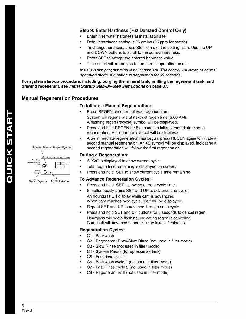
Manual Regeneration Procedures
To Initiate a Manual Regeneration:• Press REGEN once for delayed regeneration.
System will regenerate at next set regen time (2:00 AM).A flashing regen (recycle) symbol will be displayed.
• Press and hold REGEN for 5 seconds to initiate immediate manual regeneration. A solid regen symbol will be displayed.
• After immediate regeneration has begun, press REGEN again to initiate a second manual regeneration. An X2 symbol will be displayed, indicating a second regeneration will follow the first regeneration.
During a Regeneration:• A "C#" is displayed to show current cycle.• Total regen time remaining is displayed on screen.• Press and hold SET to show current cycle time remaining.
To Advance Regeneration Cycles:• Press and hold SET - showing current cycle time.• Simultaneously press SET and UP to advance one cycle.
An hourglass will display while cam is advancing.When cam reaches next cycle, "C2" will be displayed.
• Repeat SET and UP to advance through each cycle.• Press and hold SET and UP buttons for 5 seconds to cancel regen.
Hourglass will begin flashing, indicating regen is cancelled.Camshaft will advance to home - may take 1-2 minutes.
Regeneration Cycles:• C1 - Backwash• C2 - Regenerant Draw/Slow Rinse (not used in filter mode)• C3 - Slow Rinse (not used in filter mode)• C4 - System Pause (to repressurize tank)• C5 - Fast rinse cycle 1• C6 - Backwash cycle 2 (not used in filter mode)• C7 - Fast Rinse cycle 2 (not used in filter mode)• C8 - Regenerant refill (not used in filter mode)
Time & Day
Regen Time & Day
Salt
SU MO TU WE TH FR SA DAYS
CCapacity
Hardness
MIN
x2
Cycle IndicatorRegen Symbol
Second Manual Regen Symbol
6 Rev J
QU
ICK
STA
RT
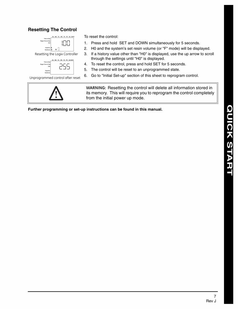
Resetting The ControlTo reset the control:
1. Press and hold SET and DOWN simultaneously for 5 seconds.2. H0 and the system’s set resin volume (or "F" mode) will be displayed.3. If a history value other than "H0" is displayed, use the up arrow to scroll
through the settings until "H0" is displayed.4. To reset the control, press and hold SET for 5 seconds.5. The control will be reset to an unprogrammed state.
6. Go to "Initial Set-up" section of this sheet to reprogram control.
Further programming or set-up instructions can be found in this manual.
Unprogrammed control after reset
Resetting the Logix Controller
Time & Day
Regen Time & Day
Salt
SU MO TU WE TH FR SA DAYS
HCapacity
Hardness
Time & Day
Regen Time & Day
Salt
SU MO TU WE TH FR SA DAYS
Capacity
Hardness
WARNING: Resetting the control will delete all information stored in its memory. This will require you to reprogram the control completely from the initial power up mode.
7Rev J

MANUAL OVERVIEW
How To Use This ManualThis installation manual is designed to guide the installer through the process of installing and starting conditioners featuring the 700 Logix series controllers.
This manual is a reference and will not include every system installation situation. The person installing this equipment should have:
• Training in the 700 Logix series controllers and water conditioner installation
• Knowledge of water conditioning and how to determine proper control settings
• Basic plumbing skills• The directional instructions "left" and “right" are determined by looking at
the front of the unit.
Icons That Appear In This Manual
Left Side Right Side
WARNING: Failure to follow this instruction can result in personal injury or damage to the equipment.
NOTE: This will make the process easier if followed.
8 How To Use This ManualRev J

EQUIPMENT INSTALLATION
General Warnings And Safety Information
The systems below have been Tested and Certified by WQA to NSF/ANSI Std. 44 and NSF/ANSI 372 for “Lead Free” compliance.
The 255 valve and 268 valve have been Tested and Certified by WQA to NSF/ANSI Std 61 Section 8 Mechanical Devices.
WQA Certified 255 Valve Systems WQA Certified 268 Valve Systems
255-742-075-844 268-742-948
255-742-100-948 268-742-150-1054
255-742-100-1040 268-742-200-1248
255-742-150-1054 268-762-948
255-762-075-844 268-762-150-1054
255-762-100-948 268-768-200-1248
255-762-100-1040
255-762-150-1054
TEST
EDAND CERTIF
IED
UNDER
INDUSTRY ST
AN
DARDS
General Warnings And Safety Information 9Rev J
W
ATE
R S
OFT
EN
ER
PE
RFO
RM
AN
CE
DA
TA S
HE
ET
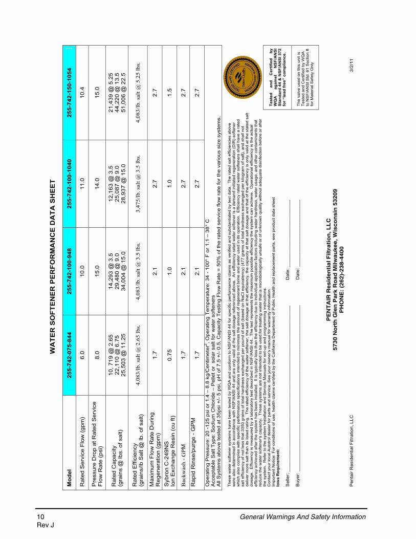
Mod
el25
5-74
2-07
5-84
4
255-
742-
100-
948
25
5-74
2-10
0-10
40
255-
742-
150-
1054
Rat
ed S
ervi
ce F
low
(gp
m)
6.0
10.0
11.0
10.4
Pre
ssur
e D
rop
at R
ated
Ser
vice
F
low
Rat
e (p
si)
8.0
15.0
14.0
15.0
Rat
ed C
apac
ity
(g
rain
s @
lbs.
of s
alt)
10, 7
19 @
2.6
5 22
,110
@ 6
.75
25,5
03 @
11.
25
14,2
93 @
3.5
29
,480
@ 9
.0
34,0
04 @
15.
0
12,1
63 @
3.5
25
,087
@ 9
.0
28,9
37 @
15.
0
21,4
39 @
5.2
5 44
,220
@ 1
3.5
51,0
06 @
22.
5
Rat
ed E
ffici
ency
(g
rain
s/lb
Sal
t @ lb
. of s
alt)
4,
083/
lb. s
alt @
2.6
5 lb
s.
4,08
3/lb
. sal
t @ 3
.5 lb
s.
3,47
5/lb
. sal
t @ 3
.5 lb
s.
4,08
3/lb
. sal
t @ 5
.25
lbs.
Max
imum
Flo
w R
ate
Dur
ing
Reg
ener
atio
n (g
pm)
1.7
2.1
2.7
2.7
Syb
ron
C-2
49N
S
Ion
Exc
hang
e R
esin
(cu
ft)
0.75
1.0
1.0
1.5
Bac
kwas
h - G
PM1.
72.
12.
72.
7
Rap
id R
inse
/pur
ge -
GP
M
1.7
2.1
2.7
2.7
Ope
ratin
g P
ress
ure:
20
-125
psi
or
1.4
– 8.
8 kg
/Cen
timet
er2 , O
pera
ting
Tem
pera
ture
: 34
- 10
0° F
or
1.1
– 38
° C
Acc
epta
ble
Sal
t Typ
e: S
odiu
m C
hlor
ide
– P
elle
t or
sol
ar s
alt f
or w
ater
sof
tene
rs
All
Sys
tem
s ab
ove
test
ed a
t 35p
si +
/- 5
psi
, pH
of 7
.5 +
/- 0
.5, C
apac
ity T
estin
g F
low
Rat
e =
50%
of t
he r
ated
ser
vice
flow
rat
e fo
r th
e va
rious
siz
e sy
stem
s.
Test
ed
and
Cer
tifie
d by
W
QA
ag
ains
t N
SF/
AN
SI
Sta
ndar
d 44
& N
SF/
AN
SI 3
72
for
“lea
d fr
ee”
com
plia
nce.
The
se w
ater
sof
tene
r sy
stem
s ha
ve b
een
test
ed b
y W
QA
and
con
form
to N
SF
/AN
SI 4
4 fo
r spe
cific
per
form
ance
cla
ims
as v
erifi
ed a
nd s
ubst
antia
ted
by te
st d
ata.
The
rat
ed s
alt e
ffici
enci
es a
bove
w
ere
also
det
erm
ined
in a
ccor
danc
e w
ith N
SF/
AN
SI 4
4 an
d ar
e on
ly v
alid
at t
he s
alt d
osag
e re
fere
nced
abo
ve.
An
effic
ienc
y ra
ted
wat
er s
ofte
ner
is a
dem
and
initi
ated
reg
ener
atio
n (D
IR) s
ofte
ner
whi
ch a
lso
com
plie
s w
ith s
peci
fic p
erfo
rman
ce s
peci
ficat
ions
inte
nded
to m
inim
ize
the
amou
nt o
f reg
ener
ant b
rine
and
wat
er u
sed
in it
s op
erat
ion.
Effi
cien
cy r
ated
wat
er s
ofte
ners
sha
ll ha
ve a
rat
ed
salt
effic
ienc
y of
not
less
that
335
0 gr
ains
of t
otal
har
dnes
s ex
chan
ged
per
poun
d of
sal
t (ba
sed
on N
aCl e
quiv
alen
cy)
(477
gra
ms
of to
tal h
ardn
ess
exch
ange
d pe
r kilo
gram
of s
alt),
and
sha
ll no
t de
liver
mor
e sa
lt th
an it
s lis
ted
ratin
g. T
he r
ated
effi
cien
cy o
f the
wat
er s
ofte
ner,
the
salt
dosa
ge a
t tha
t effi
cien
cy, t
he c
apac
ity a
t tha
t sal
t dos
age
and
that
of t
he e
ffici
ency
is o
nly
valid
at t
he s
tate
d sa
lt do
sage
. E
ffici
ency
is m
easu
red
by a
labo
rato
ry te
st d
escr
ibed
in N
SF
/AN
SI 4
4. T
he te
st r
epre
sent
s th
e m
axim
um p
ossi
ble
effic
ienc
y th
e sy
stem
can
ach
ieve
. O
pera
tiona
l effi
cien
cy is
the
actu
al
effic
ienc
y ac
hiev
ed a
fter
the
syst
em h
as b
een
inst
alle
d. I
t is
typi
cally
less
than
the
effic
ienc
y du
e to
indi
vidu
al a
pplic
atio
n fa
ctor
s in
clud
ing
wat
er h
ardn
ess,
wat
er u
sage
, and
oth
er c
onta
min
ants
that
re
duce
the
wat
er s
ofte
ner’s
cap
acity
. T
hese
sys
tem
s ar
e no
t int
ende
d to
be
used
for t
reat
ing
wat
er th
at is
mic
robi
olog
ical
ly u
nsaf
e or
of u
nkno
wn
qual
ity w
ithou
t ade
quat
e di
sinf
ectio
n be
fore
or
afte
r th
e sy
stem
. R
efer
to th
e sy
stem
Inst
alla
tion
and
Ser
vice
Man
uals
for s
et-u
p an
d pr
ogra
mm
ing
inst
ruct
ions
. C
onta
ct y
our
loca
l Aut
otro
l dea
ler
for
part
s an
d se
rvic
e. S
ee y
our
owne
r’s m
anua
l for
war
rant
y in
form
atio
n.
Impo
rtan
t Not
ice:
For
con
ditio
ns o
f use
, hea
lth c
laim
s ce
rtifi
ed b
y th
e C
alifo
rnia
Dep
artm
ent o
f Pub
lic H
ealth
and
rep
lace
men
t par
ts, s
ee p
rodu
ct d
ata
shee
t Io
wa
Req
uire
men
t:
Sel
ler:
___
____
____
____
____
____
____
____
____
____
____
____
____
____
____
___
Dat
e: _
____
____
____
____
____
____
Buy
er: _
____
____
____
____
____
____
____
____
____
____
____
____
____
____
____
_
D
ate:
___
____
____
____
____
____
__
The
val
ve u
sed
on th
is u
nit i
s T
este
d an
d C
ertif
ied
by W
QA
to
NS
F/A
NS
I Std
. 61
Sec
tion
8 fo
r M
ater
ial S
afet
y O
nly
PE
NT
AIR
Resid
en
tial F
iltr
ati
on
, L
LC
5730 N
ort
h G
len
Park
Ro
ad
Milw
au
kee, W
isco
ns
in 5
3209
PH
ON
E:
(262
)-2
38-4
400
Pen
tair
Res
iden
tial F
iltra
tion,
LLC
3
/2/1
1
10 General Warnings And Safety InformationRev J
WA
TER
SO
FTEN
ER P
ERFO
RM
AN
CE
DA
TA S
HEE
T
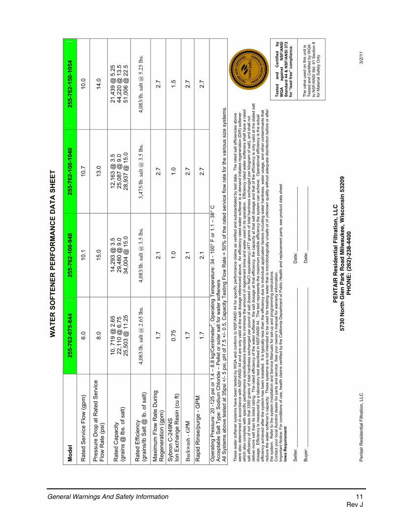
Mod
el25
5-76
2-07
5-84
4
255-
762-
100-
948
25
5-76
2-10
0-10
40
255-
762-
150-
1054
Rat
ed S
ervi
ce F
low
(gpm
) 6.
010
.110
.710
.0
Pre
ssur
e D
rop
at R
ated
Ser
vice
Fl
ow R
ate
(psi
) 8.
015
.013
.014
.0
Rat
ed C
apac
ity
(g
rain
s @
lbs.
of s
alt)
10, 7
19 @
2.6
5 22
,110
@ 6
.75
25,5
03 @
11.
25
14,2
93 @
3.5
29
,480
@ 9
.0
34,0
04 @
15.
0
12,1
63 @
3.5
25
,087
@ 9
.0
28,9
37 @
15.
0
21,4
39 @
5.2
5 44
,220
@ 1
3.5
51,0
06 @
22.
5
Rat
ed E
ffici
ency
(g
rain
s/lb
Sal
t @ lb
. of s
alt)
4,08
3/lb
. sal
t @ 2
.65
lbs.
4,08
3/lb
. sal
t @ 3
.5 lb
s. 3,
475/
lb. s
alt @
3.5
lbs.
4,08
3/lb
. sal
t @ 5
.25
lbs.
Max
imum
Flo
w R
ate
Dur
ing
Reg
ener
atio
n (g
pm)
1.7
2.1
2.7
2.7
Syb
ron
C-2
49N
S
Ion
Exc
hang
e R
esin
(cu
ft)
0.75
1.0
1.0
1.5
Bac
kwas
h - G
PM1.
72.
12.
72.
7
Rap
id R
inse
/pur
ge -
GP
M
1.7
2.1
2.7
2.7
Ope
ratin
g P
ress
ure:
20
-125
psi
or 1
.4 –
8.8
kg/
Cen
timet
er2 , O
pera
ting
Tem
pera
ture
: 34
- 100
° F
or 1
.1 –
38°
C
A
ccep
tabl
e S
alt T
ype:
Sod
ium
Chl
orid
e –
Pel
let o
r sol
ar s
alt f
or w
ater
sof
tene
rs
All
Sys
tem
s ab
ove
test
ed a
t 35p
si +
/- 5
psi,
pH o
f 7.5
+/-
0.5,
Cap
acity
Tes
ting
Flow
Rat
e =
50%
of t
he ra
ted
serv
ice
flow
rate
for t
he v
ario
us s
ize
syst
ems.
Test
ed
and
Cer
tifie
d by
W
QA
ag
ains
t N
SF/A
NSI
St
anda
rd 4
4 &
NSF
/AN
SI 3
72
for “
lead
free
” co
mpl
ianc
e.
Thes
e w
ater
sof
tene
r sys
tem
s ha
ve b
een
test
ed b
y W
QA
and
con
form
to N
SF/
AN
SI 4
4 fo
r spe
cific
per
form
ance
cla
ims
as v
erifi
ed a
nd s
ubst
antia
ted
by te
st d
ata.
The
rate
d sa
lt ef
ficie
ncie
s ab
ove
wer
e al
so d
eter
min
ed in
acc
orda
nce
with
NS
F/A
NS
I 44
and
are
only
val
id a
t the
sal
t dos
age
refe
renc
ed a
bove
. A
n ef
ficie
ncy
rate
d w
ater
sof
tene
r is
a de
man
d in
itiat
ed re
gene
ratio
n (D
IR) s
ofte
ner
whi
ch a
lso
com
plie
s w
ith s
peci
fic p
erfo
rman
ce s
peci
ficat
ions
inte
nded
to m
inim
ize
the
amou
nt o
f reg
ener
ant b
rine
and
wat
er u
sed
in it
s op
erat
ion.
Effi
cien
cy ra
ted
wat
er s
ofte
ners
sha
ll ha
ve a
rate
d sa
lt ef
ficie
ncy
of n
ot le
ss th
at 3
350
grai
ns o
f tot
al h
ardn
ess
exch
ange
d pe
r pou
nd o
f sal
t (ba
sed
on N
aCl e
quiv
alen
cy) (
477
gram
s of
tota
l har
dnes
s ex
chan
ged
per k
ilogr
am o
f sal
t), a
nd s
hall
not
deliv
er m
ore
salt
than
its
liste
d ra
ting.
The
rate
d ef
ficie
ncy
of th
e w
ater
sof
tene
r, th
e sa
lt do
sage
at t
hat e
ffici
ency
, the
cap
acity
at t
hat s
alt d
osag
e an
d th
at o
f the
effi
cien
cy is
onl
y va
lid a
t the
sta
ted
salt
dosa
ge.
Effi
cien
cy is
mea
sure
d by
a la
bora
tory
test
des
crib
ed in
NS
F/A
NS
I 44.
The
test
repr
esen
ts th
e m
axim
um p
ossi
ble
effic
ienc
y th
e sy
stem
can
ach
ieve
. O
pera
tiona
l effi
cien
cy is
the
actu
al
effic
ienc
y ac
hiev
ed a
fter t
he s
yste
m h
as b
een
inst
alle
d. I
t is
typi
cally
less
than
the
effic
ienc
y du
e to
indi
vidu
al a
pplic
atio
n fa
ctor
s in
clud
ing
wat
er h
ardn
ess,
wat
er u
sage
, and
oth
er c
onta
min
ants
that
re
duce
the
wat
er s
ofte
ner’s
cap
acity
. Th
ese
syst
ems
are
not i
nten
ded
to b
e us
ed fo
r tre
atin
g w
ater
that
is m
icro
biol
ogic
ally
uns
afe
or o
f unk
now
n qu
ality
with
out a
dequ
ate
disi
nfec
tion
befo
re o
r afte
r th
e sy
stem
. R
efer
to th
e sy
stem
Inst
alla
tion
and
Ser
vice
Man
uals
for s
et-u
p an
d pr
ogra
mm
ing
inst
ruct
ions
. C
onta
ct y
our l
ocal
Aut
otro
l dea
ler f
or p
arts
and
ser
vice
. See
you
r ow
ner’s
man
ual f
or w
arra
nty
info
rmat
ion.
Im
porta
nt N
otic
e: F
or c
ondi
tions
of u
se, h
ealth
cla
ims
certi
fied
by th
e C
alifo
rnia
Dep
artm
ent o
f Pub
lic H
ealth
and
repl
acem
ent p
arts
, see
pro
duct
dat
a sh
eet
Iow
a R
equi
rem
ent:
Sel
ler:
____
____
____
____
____
____
____
____
____
____
____
____
____
____
____
__
D
ate:
___
____
____
____
____
____
__
Buy
er: _
____
____
____
____
____
____
____
____
____
____
____
____
____
____
____
_
D
ate:
___
____
____
____
____
____
__
The
valv
e us
ed o
n th
is u
nit i
s Te
sted
and
Cer
tifie
d by
WQ
A
to N
SF/
AN
SI S
td. 6
1 S
ectio
n 8
for M
ater
ial S
afet
y O
nly
PE
NT
AIR
Res
iden
tial
Filt
rati
on
, LL
C
5730
No
rth
Gle
n P
ark
Ro
ad M
ilwau
kee,
Wis
con
sin
532
09
PH
ON
E:
(262
)-23
8-44
00
Pen
tair
Res
iden
tial F
iltra
tion,
LLC
3
/2/1
1
General Warnings And Safety Information 11Rev J
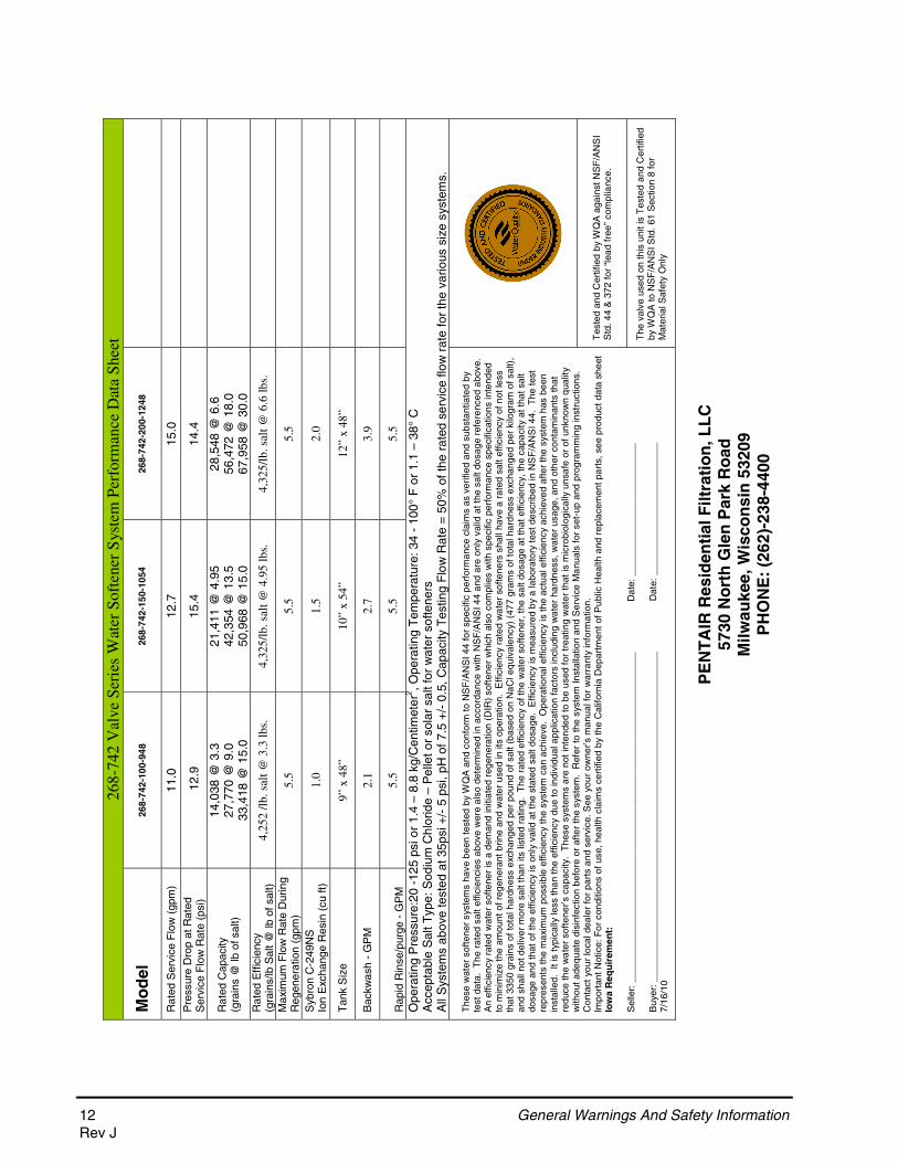
268-
742
Val
ve S
erie
s W
ater
Sof
tene
r S
yste
m P
erfo
rman
ce D
ata
Shee
t
Mo
del
268-
742-
100-
948
268-
742-
150-
1054
268-
742-
200-
1248
Rat
ed S
ervi
ce F
low
(gp
m)
11.0
12
.7
15.0
Pre
ssur
e D
rop
at R
ated
S
ervi
ce F
low
Rat
e (p
si)
12.
9 15
.4
14.4
Rat
ed C
apac
ity
(g
rain
s @
lb o
f sal
t)
14,0
38 @
3.3
27
,770
@ 9
.0
33,4
18 @
15.
0
21,4
11 @
4.9
5 42
,354
@ 1
3.5
50,9
68 @
15.
0
28,5
48 @
6.6
56
,472
@ 1
8.0
67,9
58 @
30.
0
Rat
ed E
ffici
ency
(gra
ins/
lb S
alt @
lb o
f sal
t)
4,25
2 /l
b. s
alt @
3.3
lbs.
4,
325/
lb. s
alt @
4.9
5 lb
s.
4,32
5/lb
. sal
t @ 6
.6 lb
s.
Max
imum
Flo
w R
ate
Dur
ing
Reg
ener
atio
n (g
pm)
5.5
5.5
5.5
Syb
ron
C-2
49N
S
Io
n E
xcha
nge
Res
in (
cu ft
) 1.
0 1.
5 2.
0
Tan
k S
ize
9� x
48�
10
� x
54�
12�
x 48
�
Bac
kwas
h -
GP
M
2.1
2.7
3.9
R
apid
Rin
se/p
urge
- G
PM
5.
5 5.
5 5.
5
Ope
ratin
g P
ress
ure:
20 -
125
psi o
r 1.
4 –
8.8
kg/C
entim
eter
2 , Ope
ratin
g T
empe
ratu
re: 3
4 -
100°
F o
r 1.
1 –
38°
C
Acc
epta
ble
Sal
t Typ
e: S
odiu
m C
hlor
ide
– P
elle
t or
sola
r sa
lt fo
r w
ater
sof
tene
rs
All
Sys
tem
s ab
ove
test
ed a
t 35p
si +
/- 5
psi
, pH
of 7
.5 +
/- 0
.5, C
apac
ity T
estin
g F
low
Rat
e =
50%
of t
he r
ated
ser
vice
flow
rat
e fo
r th
e va
rious
siz
e sy
stem
s.
Tes
ted
and
Cer
tifie
d by
WQ
A a
gain
st N
SF
/AN
SI
Std
. 44
& 3
72 fo
r “le
ad fr
ee”
com
plia
nce.
The
se w
ater
sof
tene
r sy
stem
s ha
ve b
een
test
ed b
y W
QA
and
con
form
to N
SF
/AN
SI 4
4 fo
r sp
ecifi
c pe
rfor
man
ce c
laim
s as
ver
ified
and
sub
stan
tiate
d by
te
st d
ata.
The
rat
ed s
alt e
ffici
enci
es a
bove
wer
e al
so d
eter
min
ed in
acc
orda
nce
with
NS
F/A
NS
I 44
and
are
only
val
id a
t the
sal
t dos
age
refe
renc
ed a
bove
. A
n ef
ficie
ncy
rate
d w
ater
sof
tene
r is
a d
eman
d in
itiat
ed r
egen
erat
ion
(DIR
) so
ftene
r w
hich
als
o co
mpl
ies
with
spe
cific
per
form
ance
spe
cific
atio
ns in
tend
ed
to m
inim
ize
the
amou
nt o
f reg
ener
ant b
rine
and
wat
er u
sed
in it
s op
erat
ion.
Effi
cien
cy r
ated
wat
er s
ofte
ners
sha
ll ha
ve a
rat
ed s
alt e
ffici
ency
of n
ot le
ss
that
335
0 gr
ains
of t
otal
har
dnes
s ex
chan
ged
per
poun
d of
sal
t (ba
sed
on N
aCl e
quiv
alen
cy)
(477
gra
ms
of to
tal h
ardn
ess
exch
ange
d pe
r ki
logr
am o
f sal
t),
and
shal
l not
del
iver
mor
e sa
lt th
an it
s lis
ted
ratin
g. T
he r
ated
effi
cien
cy o
f the
wat
er s
ofte
ner,
the
salt
dosa
ge a
t tha
t effi
cien
cy, t
he c
apac
ity a
t tha
t sal
t do
sage
and
that
of t
he e
ffici
ency
is o
nly
valid
at t
he s
tate
d sa
lt do
sage
. E
ffici
ency
is m
easu
red
by
a la
bora
tory
test
des
crib
ed in
NS
F/A
NS
I 44.
The
test
re
pres
ents
the
max
imum
pos
sibl
e ef
ficie
ncy
the
syst
em c
an a
chie
ve.
Ope
ratio
nal e
ffici
ency
is th
e ac
tual
effi
cien
cy a
chie
ved
afte
r th
e sy
stem
has
bee
n in
stal
led.
It
is ty
pica
lly le
ss th
an th
e ef
ficie
ncy
due
to in
divi
dual
app
licat
ion
fact
ors
incl
udin
g w
ater
har
dnes
s, w
ater
usa
ge, a
nd o
ther
con
tam
inan
ts th
at
redu
ce th
e w
ater
sof
tene
r’s c
apac
ity.
The
se s
yste
ms
are
not i
nten
ded
to b
e us
ed fo
r tr
eatin
g w
ater
that
is m
icro
biol
ogic
ally
uns
afe
or o
f unk
now
n qu
ality
w
ithou
t ade
quat
e di
sinf
ectio
n be
fore
or
afte
r th
e sy
stem
. R
efer
to th
e sy
stem
Inst
alla
tion
and
Ser
vice
Man
uals
for
set-
up a
nd p
rogr
amm
ing
inst
ruct
ions
. C
onta
ct y
our
loca
l dea
ler
for
part
s an
d se
rvic
e. S
ee y
our
owne
r’s m
anua
l for
war
rant
y in
form
atio
n.
Impo
rtan
t Not
ice:
For
con
ditio
ns o
f use
, hea
lth c
laim
s ce
rtifi
ed b
y th
e C
alifo
rnia
Dep
artm
ent o
f Pub
lic H
ealth
and
rep
lace
men
t par
ts, s
ee p
rodu
ct d
ata
shee
t Io
wa
Req
uir
emen
t:
Sel
ler:
___
____
____
____
____
____
____
____
____
____
____
____
____
____
____
___
Dat
e: _
____
____
____
____
____
____
B
uyer
: ___
____
____
____
____
____
____
____
____
____
____
____
____
____
____
___
Dat
e: _
____
____
____
____
____
____
7/
16/1
0
The
val
ve u
sed
on th
is u
nit i
s T
este
d an
d C
ertif
ied
by W
QA
to N
SF
/AN
SI S
td. 6
1 S
ectio
n 8
for
Mat
eria
l Saf
ety
Onl
y
P
EN
TA
IR R
esid
enti
al F
iltra
tio
n, L
LC
57
30 N
ort
h G
len
Par
k R
oad
M
ilwau
kee,
Wis
con
sin
532
09
PH
ON
E:
(262
)-23
8-44
00
12 General Warnings And Safety InformationRev J
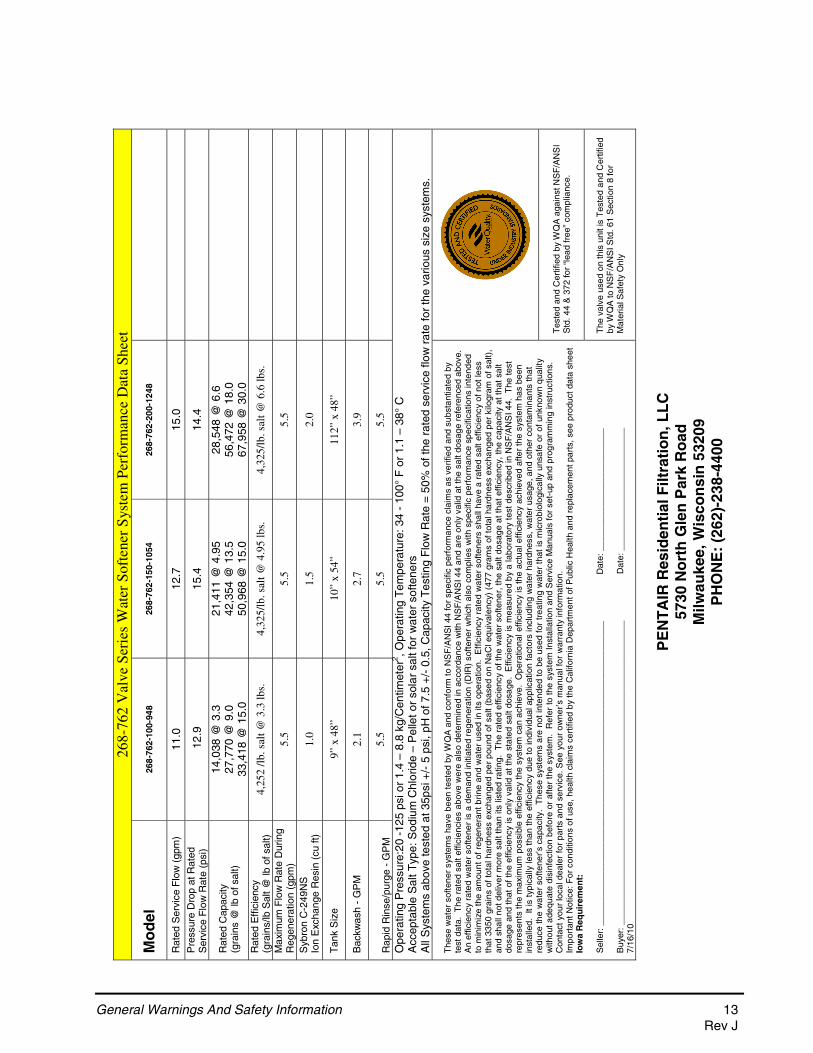
268-
762
Val
ve S
erie
s W
ater
Sof
tene
r S
yste
m P
erfo
rman
ce D
ata
Shee
t
Mo
del
268-
762-
100-
948
268-
762-
150-
1054
268-
762-
200-
1248
Rat
ed S
ervi
ce F
low
(gp
m)
11.0
12
.7
15.0
Pre
ssur
e D
rop
at R
ated
S
ervi
ce F
low
Rat
e (p
si)
12.
9 15
.4
14.4
Rat
ed C
apac
ity
(g
rain
s @
lb o
f sal
t)
14,0
38 @
3.3
27
,770
@ 9
.0
33,4
18 @
15.
0
21,4
11 @
4.9
5 42
,354
@ 1
3.5
50,9
68 @
15.
0
28,5
48 @
6.6
56
,472
@ 1
8.0
67,9
58 @
30.
0
Rat
ed E
ffici
ency
(gra
ins/
lb S
alt @
lb o
f sal
t)
4,25
2 /l
b. s
alt @
3.3
lbs.
4,
325/
lb. s
alt @
4.9
5 lb
s.
4,32
5/lb
. sal
t @ 6
.6 lb
s.
Max
imum
Flo
w R
ate
Dur
ing
Reg
ener
atio
n (g
pm)
5.5
5.5
5.5
Syb
ron
C-2
49N
S
Io
n E
xcha
nge
Res
in (
cu ft
) 1.
0 1.
5 2.
0
Tan
k S
ize
9� x
48�
10
� x
54�
112�
x 4
8�
Bac
kwas
h -
GP
M
2.1
2.7
3.9
R
apid
Rin
se/p
urge
- G
PM
5.
5 5.
5 5.
5
Ope
ratin
g P
ress
ure:
20 -
125
psi o
r 1.
4 –
8.8
kg/C
entim
eter
2 , Ope
ratin
g T
empe
ratu
re: 3
4 -
100°
F o
r 1.
1 –
38°
C
Acc
epta
ble
Sal
t Typ
e: S
odiu
m C
hlor
ide
– P
elle
t or
sola
r sa
lt fo
r w
ater
sof
tene
rs
All
Sys
tem
s ab
ove
test
ed a
t 35p
si +
/- 5
psi
, pH
of 7
.5 +
/- 0
.5, C
apac
ity T
estin
g F
low
Rat
e =
50%
of t
he r
ated
ser
vice
flow
rat
e fo
r th
e va
rious
siz
e sy
stem
s.
Tes
ted
and
Cer
tifie
d by
WQ
A a
gain
st N
SF
/AN
SI
Std
. 44
& 3
72 fo
r “le
ad fr
ee”
com
plia
nce.
The
se w
ater
sof
tene
r sy
stem
s ha
ve b
een
test
ed b
y W
QA
and
con
form
to N
SF
/AN
SI 4
4 fo
r sp
ecifi
c pe
rfor
man
ce c
laim
s as
ver
ified
and
sub
stan
tiate
d by
te
st d
ata.
The
rat
ed s
alt e
ffici
enci
es a
bove
wer
e al
so d
eter
min
ed in
acc
orda
nce
with
NS
F/A
NS
I 44
and
are
only
val
id a
t the
sal
t dos
age
refe
renc
ed a
bove
. A
n ef
ficie
ncy
rate
d w
ater
sof
tene
r is
a d
eman
d in
itiat
ed r
egen
erat
ion
(DIR
) so
ftene
r w
hich
als
o co
mpl
ies
with
spe
cific
per
form
ance
spe
cific
atio
ns in
tend
ed
to m
inim
ize
the
amou
nt o
f reg
ener
ant b
rine
and
wat
er u
sed
in it
s op
erat
ion.
Effi
cien
cy r
ated
wat
er s
ofte
ners
sha
ll ha
ve a
rat
ed s
alt e
ffici
ency
of n
ot le
ss
that
335
0 gr
ains
of t
otal
har
dnes
s ex
chan
ged
per
poun
d of
sal
t (ba
sed
on N
aCl e
quiv
alen
cy)
(477
gra
ms
of to
tal h
ardn
ess
exch
ange
d pe
r ki
logr
am o
f sal
t),
and
shal
l not
del
iver
mor
e sa
lt th
an it
s lis
ted
ratin
g. T
he r
ated
effi
cien
cy o
f the
wat
er s
ofte
ner,
the
salt
dosa
ge a
t tha
t effi
cien
cy, t
he c
apac
ity a
t tha
t sal
t do
sage
and
that
of t
he e
ffici
ency
is o
nly
valid
at t
he s
tate
d sa
lt do
sage
. E
ffici
ency
is m
easu
red
by
a la
bora
tory
test
des
crib
ed in
NS
F/A
NS
I 44.
The
test
re
pres
ents
the
max
imum
pos
sibl
e ef
ficie
ncy
the
syst
em c
an a
chie
ve.
Ope
ratio
nal e
ffici
ency
is th
e ac
tual
effi
cien
cy a
chie
ved
afte
r th
e sy
stem
has
bee
n in
stal
led.
It
is ty
pica
lly le
ss th
an th
e ef
ficie
ncy
due
to in
divi
dual
app
licat
ion
fact
ors
incl
udin
g w
ater
har
dnes
s, w
ater
usa
ge, a
nd o
ther
con
tam
inan
ts th
at
redu
ce th
e w
ater
sof
tene
r’s c
apac
ity.
The
se s
yste
ms
are
not i
nten
ded
to b
e us
ed fo
r tr
eatin
g w
ater
that
is m
icro
biol
ogic
ally
uns
afe
or o
f unk
now
n qu
ality
w
ithou
t ade
quat
e di
sinf
ectio
n be
fore
or
afte
r th
e sy
stem
. R
efer
to th
e sy
stem
Inst
alla
tion
and
Ser
vice
Man
uals
for
set-
up a
nd p
rogr
amm
ing
inst
ruct
ions
. C
onta
ct y
our
loca
l dea
ler
for
part
s an
d se
rvic
e. S
ee y
our
owne
r’s m
anua
l for
war
rant
y in
form
atio
n.
Impo
rtan
t Not
ice:
For
con
ditio
ns o
f use
, hea
lth c
laim
s ce
rtifi
ed b
y th
e C
alifo
rnia
Dep
artm
ent o
f Pub
lic H
ealth
and
rep
lace
men
t par
ts, s
ee p
rodu
ct d
ata
shee
t Io
wa
Req
uir
emen
t:
Sel
ler:
___
____
____
____
____
____
____
____
____
____
____
____
____
____
____
___
Dat
e: _
____
____
____
____
____
____
B
uyer
: ___
____
____
____
____
____
____
____
____
____
____
____
____
____
____
___
Dat
e: _
____
____
____
____
____
____
7/
16/1
0
The
val
ve u
sed
on th
is u
nit i
s T
este
d an
d C
ertif
ied
by W
QA
to N
SF
/AN
SI S
td. 6
1 S
ectio
n 8
for
Mat
eria
l Saf
ety
Onl
y
P
EN
TA
IR R
esid
enti
al F
iltra
tio
n, L
LC
57
30 N
ort
h G
len
Par
k R
oad
M
ilwau
kee,
Wis
con
sin
532
09
PH
ON
E:
(262
)-23
8-44
00
General Warnings And Safety Information 13Rev J
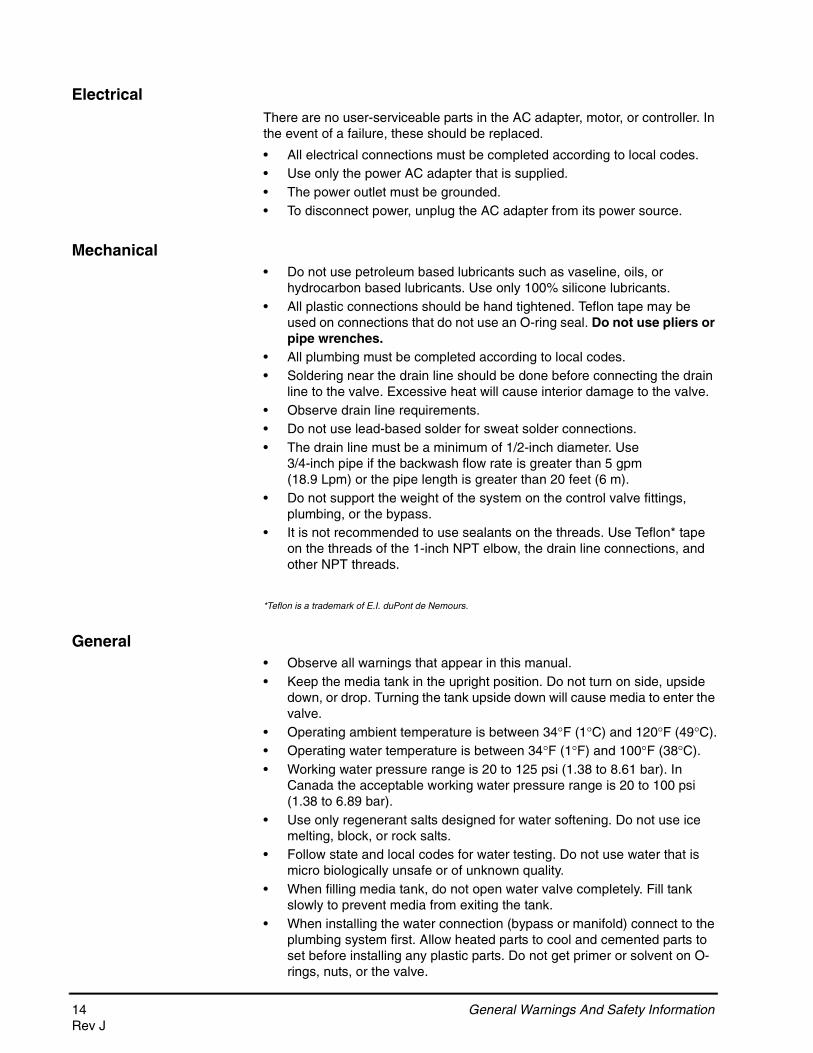
ElectricalThere are no user-serviceable parts in the AC adapter, motor, or controller. In the event of a failure, these should be replaced.
• All electrical connections must be completed according to local codes.• Use only the power AC adapter that is supplied.• The power outlet must be grounded.• To disconnect power, unplug the AC adapter from its power source.
Mechanical• Do not use petroleum based lubricants such as vaseline, oils, or
hydrocarbon based lubricants. Use only 100% silicone lubricants.• All plastic connections should be hand tightened. Teflon tape may be
used on connections that do not use an O-ring seal. Do not use pliers or pipe wrenches.
• All plumbing must be completed according to local codes.• Soldering near the drain line should be done before connecting the drain
line to the valve. Excessive heat will cause interior damage to the valve.• Observe drain line requirements.• Do not use lead-based solder for sweat solder connections.• The drain line must be a minimum of 1/2-inch diameter. Use
3/4-inch pipe if the backwash flow rate is greater than 5 gpm (18.9 Lpm) or the pipe length is greater than 20 feet (6 m).
• Do not support the weight of the system on the control valve fittings, plumbing, or the bypass.
• It is not recommended to use sealants on the threads. Use Teflon* tape on the threads of the 1-inch NPT elbow, the drain line connections, and other NPT threads.
*Teflon is a trademark of E.I. duPont de Nemours.
General• Observe all warnings that appear in this manual.• Keep the media tank in the upright position. Do not turn on side, upside
down, or drop. Turning the tank upside down will cause media to enter the valve.
• Operating ambient temperature is between 34F (1C) and 120F (49C).• Operating water temperature is between 34F (1F) and 100F (38C).• Working water pressure range is 20 to 125 psi (1.38 to 8.61 bar). In
Canada the acceptable working water pressure range is 20 to 100 psi (1.38 to 6.89 bar).
• Use only regenerant salts designed for water softening. Do not use ice melting, block, or rock salts.
• Follow state and local codes for water testing. Do not use water that is micro biologically unsafe or of unknown quality.
• When filling media tank, do not open water valve completely. Fill tank slowly to prevent media from exiting the tank.
• When installing the water connection (bypass or manifold) connect to the plumbing system first. Allow heated parts to cool and cemented parts to set before installing any plastic parts. Do not get primer or solvent on O-rings, nuts, or the valve.
14 General Warnings And Safety InformationRev J

System Regeneration Cycles (7-Cycle Operation)1. Service (Downflow) — Cycle C0:
Untreated water is directed down through the resin bed and up through the riser tube. The hardness ions attach themselves to the resin and are removed from the water. The water is conditioned as it passes through the resin bed.
2. Backwash (Upflow) — Cycles C1, C6:
The flow of water is reversed by the control valve and directed down the riser tube and up through the resin bed. During the backwash cycle, the bed is expanded and debris is flushed to the drain.
3. Brine/Slow Rinse (Downflow) — Cycles C2, C3:
The control directs water through the brine injector and brine is drawn from the regenerant tank. The brine is then directed down through the resin bed and up through the riser tube to the drain. The hardness ions are displaced by sodium ions and are sent to the drain. The resin is regenerated during the brine cycle. Brine draw is completed when the air check closes.
4. Repressurize Cycle (Hard Water Bypass Flapper Open) — Cycle C4:
This cycle allows the air and water to hydraulically balance in the valve before continuing the regeneration.
5. Fast Rinse (Downflow) — Cycles C5, C7:
The control directs water down through the resin bed and up through the riser tube to the drain. Any remaining brine residual is rinsed from the resin bed.
6. Brine Refill — Cycle C8:
Brine refill occurs during a portion of the fast rinse cycle. Water is directed to the regenerant tank at a controlled rate, to create brine for the next regeneration.
General Warnings And Safety Information 15Rev J
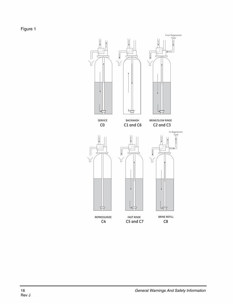
Figure 1
SERVICE BACKWASH BRINE/SLOW RINSE
FAST RINSE
From RegenerantTank
To Regenerant Tank
BRINE REFILLREPRESSURIZE
C0 C1 and C6 C2 and C3
C4 C5 and C7 C8
16 General Warnings And Safety InformationRev J
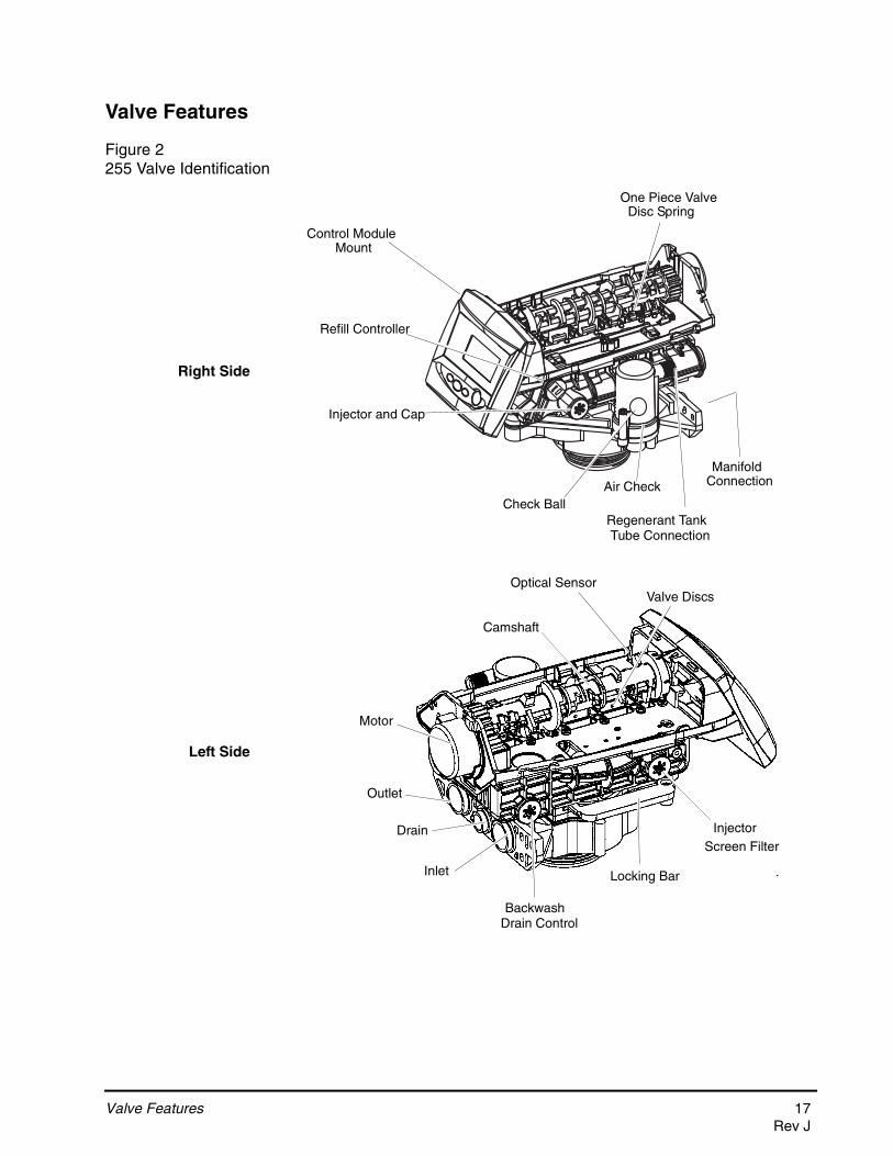
Valve Features
Figure 2255 Valve Identification
Check BallAir Check
Regenerant Tank
Refill Controller
Injector and Cap
Outlet
Inlet
Drain
Backwash
Locking Bar
Injector
Valve Discs
Camshaft
Drain Control
Screen Filter
Manifold
Motor
Optical Sensor
Control ModuleMount
One Piece Valve
Tube Connection
Connection
Disc Spring
Right Side
Left Side
Valve Features 17Rev J
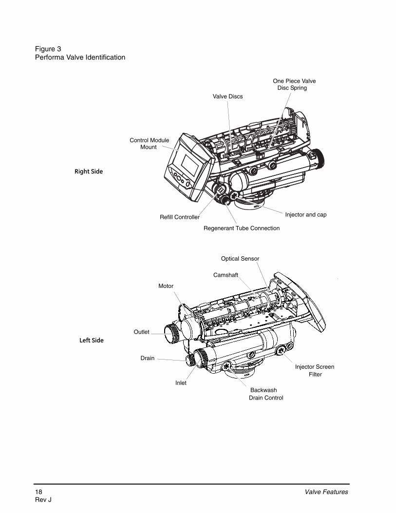
Figure 3Performa Valve Identification
Refill Controller
Regenerant Tube Connection
Injector and cap
Valve Discs
Outlet
Drain
InletBackwash
Injector Screen
Camshaft
Drain Control
Filter
Control ModuleMount
One Piece ValveDisc Spring
Motor
Optical Sensor
Right Side
Left Side
18 Valve FeaturesRev J

Figure 4700 Series Controller Identification
Location SelectionLocation of a water treatment system is important. The following conditions are required:
• Level platform or floor• Room to access equipment for maintenance and adding regenerant (salt)
to tank.• Ambient temperatures over 34F (1C) and below 120F (49C).• Water pressure below 125 psi (8.61 bar) and above 20 psi
(1.4 bar).• In Canada the water pressure must be below 100 psi (6.89 bar).• Constant electrical supply to operate the controller.• Total minimum pipe run to water heater of ten feet (three meters) to
prevent backup of hot water into system.• Local drain for discharge as close as possible.• Water line connections with shutoff or bypass valves.• Must meet any local and state codes for site of installation.• Valve is designed for minor plumbing misalignments. Do not support
weight of system on the plumbing.• Be sure all soldered pipes are fully cooled before attaching plastic valve
to the plumbing.
Outdoor LocationsWhen the water conditioning system is installed outdoors, several items must be considered.
Time & Day
Regen Time & Day
Salt
SU MO TU WE TH FR SA DAYS
LBS
PMMIN
KG
x100x2
PHC
Capacity
Hardness
LCD Display
Manual Regen ButtonDown Button
Set Button Up Button
742/762 Turbine Input or Dry Contact Signal Input
Main Motor & Optical Sensor Connection
AC Adapter (low voltage) Input
No Salt DetectorConnection
Front
Back
Location Selection 19Rev J
• Moisture — The valve and 700 controller are rated for NEMA 3 locations. Falling water should not affect performance.The system is not designed to withstand extreme humidity or water spray from below. Examples are: constant heavy mist, near corrosive environment, upwards spray from sprinkler.
• Direct Sunlight — The materials used will fade or discolor over time in direct sunlight. The integrity of the materials will not degrade to cause system failures.If it is necessary to locate the conditioner in direct sunlight, a protective outdoor cover (P/N 1267811) over the valve and controller is necessary.
• Temperature — Extreme hot or cold temperatures may cause damage to the valve or controller.Freezing temperatures will freeze the water in the valve. This will cause physical damage to the internal parts as well as the plumbing.High temperatures will affect the controller. The display may become unreadable but the controller should continue to function. When the temperature drops down into normal operating limits the display will return to normal. A protective cover, P/N 1267811, should assist with high temperature applications.
• Insects — The controller and valve have been designed to keep all but the smallest insects out of the critical areas. Any holes in the top plate can be covered with a metal foil duct work tape. The top cover should be installed securely in place.
• Wind — The Logix cover is designed to withstand a 30 mph (48 Kph) wind when properly installed on the valve.
Water Line ConnectionA bypass valve system should be installed on all water conditioning systems. Bypass valves isolate the conditioner from the water system and allow unconditioned water to be used. Service or routine maintenance procedures may also require that the system is bypassed. Figures 5, 6, and 7 show the three common bypass methods.
20 Water Line ConnectionRev J

Figure 5Series 256 bypass for use with 255 valve body
Figure 6Series 1265 bypass for use with Performa valve bodies
Figure 7Typical Globe Valve Bypass System
Normal Operation In Bypass
BYPASS BYPASS
BY
PA
SS
BY
PA
SS
In Out In Out
Normal Operation In Bypass
BYPASSBYPASS
BY
PA
SS
BY
PA
SS
WaterConditioner
In Out
WaterConditioner
In Out
WaterC
WaterC di i
Normal Operation In Bypass
WaterConditioner
WaterConditioner
Water Line Connection 21Rev J
Drain Line Connection
1. The unit should be above and not more than 20 feet (6.1 m) from the drain. Use an appropriate adapter fitting to connect 1/2-inch (1.3 cm) plastic tubing to the drain line connection of the control valve.
2. If the backwash flow rate exceeds 5 gpm (22.7 Lpm) or if the unit is located 20-40 feet (6.1-12.2 m) from drain, use 3/4-inch (1.9 cm) tubing. Use appropriate fittings to connect the 3/4-inch tubing to the3/4-inch NPT drain connection on valve.
3. The drain line may be elevated up to 6 feet (1.8 m) providing the run does not exceed 15 feet (4.6 m) and water pressure at the conditioner is not less than 40 psi (2.76 bar). Elevation can increase by 2 feet (61 cm) for each additional 10 psi (.69 bar) of water pressure at the drain connector.
4. Where the drain line is elevated but empties into a drain below the level of the control valve, form a 7-inch (18-cm) loop at the far end of the line so that the bottom of the loop is level with the drain line connection. This will provide an adequate siphon trap.
Where the drain empties into an overhead sewer line, a sink-type trap must be used.
Secure the end of the drain line to prevent it from moving.
WARNING: The inlet water must be connected to the inlet port of the valve. When replacing non-Pentair Water valves, the inlet and outlet may be reversed. It is also possible for the plumbing to be installed in an opposite order.Do not solder pipes with lead-based solder.
WARNING: Do not use tools to tighten plastic fittings. Over time, stress may break the connections. When the 1265 or 256 bypass valve is used, only hand tighten the plastic nuts.
WARNING: Do not use petroleum grease on gaskets when connecting bypass plumbing. Use only 100% silicone grease products when installing any plastic valve. Non-silicone grease may cause plastic components to fail over time.
NOTE: Standard commercial practices are expressed here. Local codes may require changes to the following suggestions. Check with local authorities before installing a system.
22 Drain Line ConnectionRev J
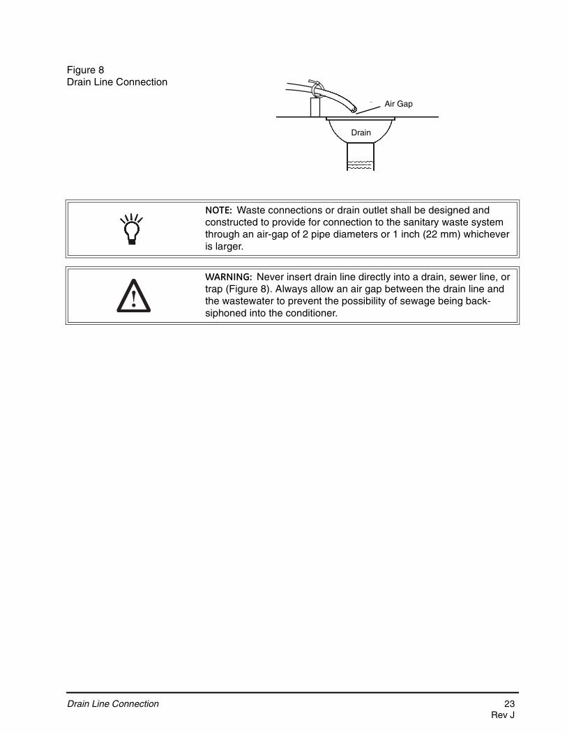
Figure 8Drain Line Connection
Right WayAir Gap
Drain
NOTE: Waste connections or drain outlet shall be designed and constructed to provide for connection to the sanitary waste system through an air-gap of 2 pipe diameters or 1 inch (22 mm) whichever is larger.
WARNING: Never insert drain line directly into a drain, sewer line, or trap (Figure 8). Always allow an air gap between the drain line and the wastewater to prevent the possibility of sewage being back-siphoned into the conditioner.
Drain Line Connection 23Rev J

Overflow Line Connection (not used with 3-cycle filter system)
In the event of a malfunction, the regenerant TANK OVERFLOW will direct “overflow” to the drain instead of spilling on the floor. This fitting should be on the side of the cabinet or regenerant tank. Most tank manufacturers include a post for the tank overflow connector.
To connect the overflow line, locate hole on side of tank. Insert overflow fitting into tank and tighten with plastic thumb nut and gasket as shown (Figure 9). Attach length of 1/2-inch (1.3-cm) I.D. tubing (not supplied) to fitting and run to drain. Do not elevate overflow line higher than overflow fitting.
Do not tie into drain line of control unit. Overflow line must be a direct, separate line from overflow fitting to drain, sewer or tub. Allow an air gap as per drain line instructions.
Figure 9Overflow Line Connection
Overflow Fitting
Drain Tubing
Air Gap
Drain
Secure hose in place
24 Overflow Line ConnectionRev J

Regenerant Line Connection (not used with 3-cycle filter system)
The regenerant line from the tank connects to the valve. Make the connections and hand tighten. Be sure that the regenerant line is secure and free from air leaks. Even a small leak may cause the regenerant line to drain out, and the conditioner will not draw regenerant from the tank. This may also introduce air into the valve causing problems with valve operation.
Most installations utilize a tank check valve. This is not necessary when using the 255 valve with the built-in aircheck. Using a tank check valve with the 255 valve with aircheck will result in premature checking of the aircheck valve, before the tank is empty.
Figure 10Air Check for 255 valve
Figure 11Regenerant Connection for Performa Valve
Regenerant Line Connection
Regenerant Line ConnectionNOTE: Be sure to use a 3/8 inch NPT plumbing connection when attaching regenerant line to the Performa valve.
Regenerant Line Connection 25Rev J
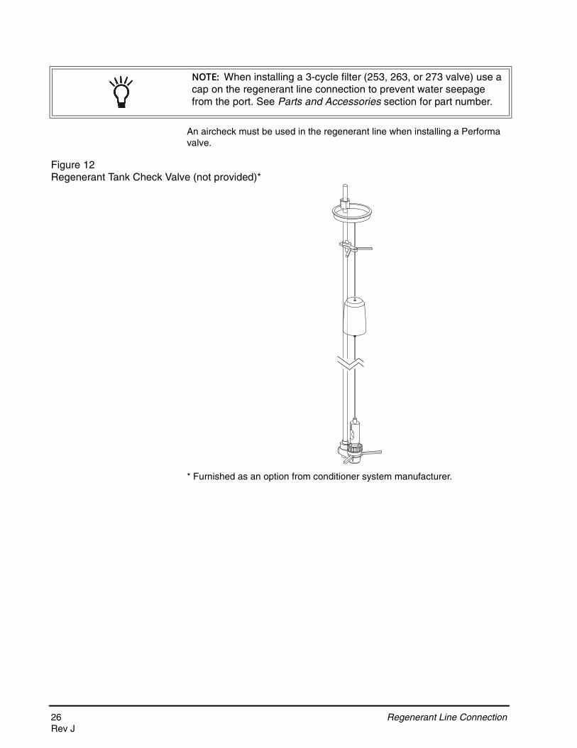
An aircheck must be used in the regenerant line when installing a Performa valve.
Figure 12 Regenerant Tank Check Valve (not provided)*
* Furnished as an option from conditioner system manufacturer.
NOTE: When installing a 3-cycle filter (253, 263, or 273 valve) use a cap on the regenerant line connection to prevent water seepage from the port. See Parts and Accessories section for part number.
26 Regenerant Line ConnectionRev J

Electrical Connection
CAUTION: This valve and control are for dry location use only unless used with a Listed Class 2 power supply suitable for outdoor use.
All 700 Series controllers operate on 12-volt alternating current power supply. This requires use of the supplied AC adapter. A variety of AC adapters are available for different applications. These AC adapters are available from your supplier. They include:
100 VAC, 120 VAC and 230 VAC AC Adapters:Make sure power source matches the rating printed on the AC adapter.
The 700 Series controller is available in two power configurations. The North American controller operates on 60 Hz. If the incoming power is 50 Hz, the "North American" controller will not function. The error code "ERR 2" will show on the display.
The "World" controller will sense the input power as 50 or 60 Hz and operate accordingly.
Controller LocationThe 700 Series controllers are designed to be mounted on the valve or attached to a flat surface. Installations that do not provide easy access to the valve can have the controller mounted for remote operation.
A remote mount connection, P/N 1256257, is available for the 700 Series controller.
AC AdapterInput
VoltageApplication Part Number
Standard wall-mount AC adapter
120V 60HzStandard indoor
application1000811
Outdoor rated AC adapter
120V 60HzUL listed for
outdoor installations
1235448
International option AC adapters
Varies based on country
Standard indoor application
See Parts Lists Section
NOTE: The power source should be constant. Be certain the AC adapter is not on a switched outlet. Power interruptions longer than 8 hours may cause the controller to lose the time and day settings. When power is restored, the day and time settings must then be re-entered.
Electrical Connection 27Rev J
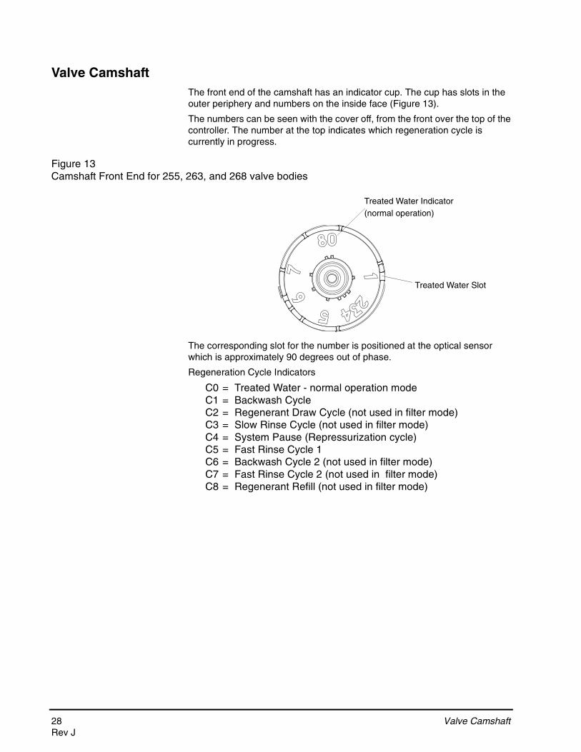
Valve CamshaftThe front end of the camshaft has an indicator cup. The cup has slots in the outer periphery and numbers on the inside face (Figure 13).
The numbers can be seen with the cover off, from the front over the top of the controller. The number at the top indicates which regeneration cycle is currently in progress.
Figure 13Camshaft Front End for 255, 263, and 268 valve bodies
The corresponding slot for the number is positioned at the optical sensor which is approximately 90 degrees out of phase.
Regeneration Cycle Indicators
C0 = Treated Water - normal operation modeC1 = Backwash CycleC2 = Regenerant Draw Cycle (not used in filter mode)C3 = Slow Rinse Cycle (not used in filter mode)C4 = System Pause (Repressurization cycle)C5 = Fast Rinse Cycle 1C6 = Backwash Cycle 2 (not used in filter mode)C7 = Fast Rinse Cycle 2 (not used in filter mode)C8 = Regenerant Refill (not used in filter mode)
Treated Water Slot
Treated Water Indicator(normal operation)
28 Valve CamshaftRev J

Valve Disc Operation
Figure 14 - 255 Valve
Figure 15 - Performa Valve (263, 268, 278)
1 Regenerant2 Inlet
4 Bypass3 Outlet
5 Rinse Drain
6 Backwash/Drain
1 Regenerant Valve
2 Bypass Valve
3 Inlet Valve
4 Outlet Valve
5 Refill Valve
7 Backwash Drain Valves
6 Rinse Drain
Valve Camshaft 29Rev J
SYSTEM DISINFECTION
Disinfection Of Water ConditionersThe materials of construction of the modern water conditioner will not support bacterial growth, nor will these materials contaminate a water supply. During normal use, a conditioner may become fouled with organic matter, or in some cases with bacteria from the water supply. This may result in an off-taste or odor in the water.
Some conditioners may need to be disinfected after installation and some conditioners will require periodic disinfection during their normal life.
Depending upon the conditions of use, the style of conditioner, the type of ion exchanger, and the disinfectant available, a choice can be made among the following methods.
Sodium or Calcium Hypochlorite
Application
These materials are satisfactory for use with polystyrene resins, synthetic gel zeolite, greensand and bentonites.
5.25% Sodium Hypochlorite
These solutions are available under trade names such as Clorox*. If stronger solutions are used, such as those sold for commercial laundries, adjust the dosage accordingly.
1. DosageA. Polystyrene resin; 1.2 fluid ounce (35.5 mL) per cubic foot.
B. Non-resinous exchangers; 0.8 fluid ounce (23.7 mL) per cubic foot.
2. Brine tank conditionersA. Backwash the conditioner and add the required amount of hypochlorite
solution to the well of the regenerant tank. The regenerant tank should have water in it to permit the solution to be carried into the conditioner.
B. Proceed with the normal regeneration.
*Clorox is a trademark of the Clorox Company.
30 Disinfection Of Water ConditionersRev J
Calcium Hypochlorite
Calcium hypochlorite, 70% available chlorine, is available in several forms including tablets and granules. These solid materials may be used directly without dissolving before use.
1. DosageA. Two grains (approximately 0.1 ounce [3 mL]) per cubic foot.
2. Regenerant tank conditionersA. Backwash the conditioner and add the required amount of hypochlorite
to the well of the regenerant tank. The regenerant tank should have water in it to permit the chlorine solution to be carried into the conditioner.
B. Proceed with the normal regeneration.
Disinfection Of Water Conditioners 31Rev J
DETERMINING IF YOU HAVE A 742 OR 762 CONTROL
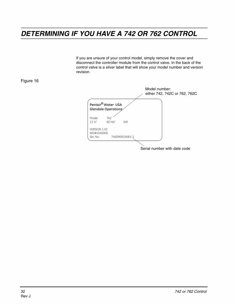
742 or 762 ControlIf you are unsure of your control model, simply remove the cover and disconnect the controller module from the control valve. In the back of the control valve is a silver label that will show your model number and version revision.
Figure 16
Model 76212 V/ 60 Hz/ 4W
VERSION 1.02WO#4340000Ser. No: 740090052683-3
Pentair Water USAGlendale Operations
®
Model number:either 742, 742C or 762, 762C
Serial number with date code
32 742 or 762 ControlRev J

GENERAL 700 SERIES INSTRUCTIONS
Display Icons 700 Controller
Figure 17
1. Days of the week. The flag immediately below the day will appear when that day has been programmed as a day the system should regenerate (used with 7-day timer programming).
2. See #3
3. This cursor is displayed when the days between regeneration are being programmed (used with .5 to 99 day regeneration programming).
4. One of these cursors will be displayed to indicate which day will be programmed into the controller.
5. "PM" indicates that the time displayed is between 12:00 noon and 12:00 midnight (there is no AM indicator). PM indicator is not used if clock mode is set to 24-hour.
6. When "MIN" is displayed, the value entered is in minute increments.
7. When g/L is displayed, the value for regenerant amount entered is in grams/Liter.
8. When "Kg" is displayed, the value entered is in kilograms or kilograins.
9. Four digits used to display the time or program value. Also used for error codes.
10. Colon flashes as part of the time display. Indicates normal operation (742 only).
g/L
PMMIN
KGx2
Time & Day
Regen Time & Day
Salt
SU MO TU WE TH FR SA DAYS
x100PHCCapacity
Hardness Lbs/ft3
1 2
3
4
5
6
7
8
9
1011
1213
14
15
16
17 18
1920
212223242526
27
28
NOTE: In normal operation and during programming, only a few of the icons will actually be displayed.
Display Icons 700 Controller 33Rev J
11. Locked/unlocked indicator. In Level I programming this is displayed when the current parameter is locked-out. It is also used in Level II programming to indicate if the displayed parameter will be locked (icon will flash) when controller is in Level I.
12. When "x2" is displayed, a second regeneration has been called for.
13. The recycle sign is displayed (flashing) when a regeneration at the next time of regeneration has been called for. Also displayed (continuous) when in regeneration.
14. The display cursor is next to "SALT" when programming the amount of regenerant. If the controller is on a 3-cycle filter then backwash time is programmed.
15. The display cursor is next to "REGEN TIME & DAY" when programming the time of regeneration and the days of regeneration.
16. The display cursor is next to "TIME & DAY" when programming the current time and day.
17. The hourglass is displayed when the motor is running. The camshaft should be turning.
18. These cursors will appear next to the item that is currently displayed.
19. X100 multiplier for large values.
20. When Lbs/ft3 is displayed the value for regenerant amount entered is in pounds/cubic foot.
21. Faucet is displayed when the current flow rate is displayed. Control may show the faucet and "0", indicating no flow.
22. Maintenance interval display turns on if the months in service exceed the value programmed in P11.
23. Used with #24, #25, and #26. Displays a sequence number or a value.
24. History Values (H). The number displayed by #23 identifies which history value is currently displayed.
25. Parameter (P). Displayed only in Level II Programming. The number displayed by #23 identifies which parameter is currently displayed.
26. Cycle (C). The number displayed by #23 is the current cycle in the regeneration sequence.
27. Hardness setting—only used with 760 and 762 controllers.
28. Capacity display—shows estimated system capacity.
34 Display Icons 700 ControllerRev J
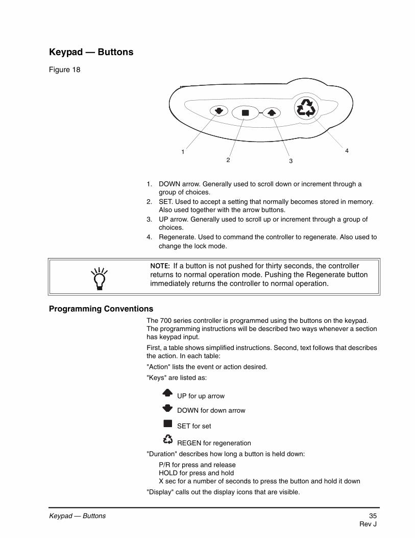
Keypad — Buttons
Figure 18
1. DOWN arrow. Generally used to scroll down or increment through a group of choices.
2. SET. Used to accept a setting that normally becomes stored in memory. Also used together with the arrow buttons.
3. UP arrow. Generally used to scroll up or increment through a group of choices.
4. Regenerate. Used to command the controller to regenerate. Also used to change the lock mode.
Programming ConventionsThe 700 series controller is programmed using the buttons on the keypad. The programming instructions will be described two ways whenever a section has keypad input.
First, a table shows simplified instructions. Second, text follows that describes the action. In each table:
"Action" lists the event or action desired.
"Keys" are listed as:
UP for up arrow
DOWN for down arrow
SET for set
REGEN for regeneration
"Duration" describes how long a button is held down:
P/R for press and releaseHOLD for press and holdX sec for a number of seconds to press the button and hold it down
"Display" calls out the display icons that are visible.
21
3
4
NOTE: If a button is not pushed for thirty seconds, the controller returns to normal operation mode. Pushing the Regenerate button immediately returns the controller to normal operation.
Keypad — Buttons 35Rev J
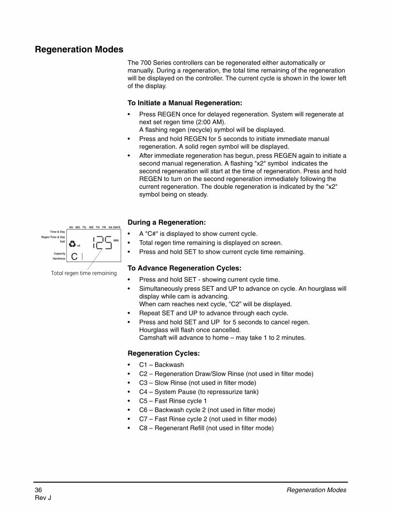
Regeneration ModesThe 700 Series controllers can be regenerated either automatically or manually. During a regeneration, the total time remaining of the regeneration will be displayed on the controller. The current cycle is shown in the lower left of the display.
To Initiate a Manual Regeneration:
• Press REGEN once for delayed regeneration. System will regenerate at next set regen time (2:00 AM).A flashing regen (recycle) symbol will be displayed.
• Press and hold REGEN for 5 seconds to initiate immediate manual regeneration. A solid regen symbol will be displayed.
• After immediate regeneration has begun, press REGEN again to initiate a second manual regeneration. A flashing "x2" symbol indicates the second regeneration will start at the time of regeneration. Press and hold REGEN to turn on the second regeneration immediately following the current regeneration. The double regeneration is indicated by the "x2" symbol being on steady.
During a Regeneration:
• A "C#" is displayed to show current cycle.• Total regen time remaining is displayed on screen.• Press and hold SET to show current cycle time remaining.
To Advance Regeneration Cycles:
• Press and hold SET - showing current cycle time.• Simultaneously press SET and UP to advance on cycle. An hourglass will
display while cam is advancing.When cam reaches next cycle, "C2” will be displayed.
• Repeat SET and UP to advance through each cycle.• Press and hold SET and UP for 5 seconds to cancel regen.
Hourglass will flash once cancelled.Camshaft will advance to home – may take 1 to 2 minutes.
Regeneration Cycles:
• C1 – Backwash• C2 – Regeneration Draw/Slow Rinse (not used in filter mode)• C3 – Slow Rinse (not used in filter mode)• C4 – System Pause (to repressurize tank)• C5 – Fast Rinse cycle 1• C6 – Backwash cycle 2 (not used in filter mode)• C7 – Fast Rinse cycle 2 (not used in filter mode)• C8 – Regenerant Refill (not used in filter mode)
Time & Day
Regen Time & Day
Salt
SU MO TU WE TH FR SA DAYS
CCapacity
Hardness
MIN
x2
Total regen time remaining
36 Regeneration ModesRev J
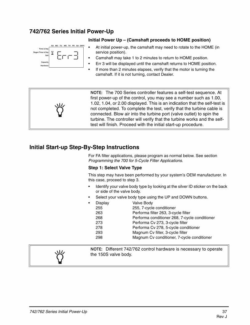
742/762 Series Initial Power-UpInitial Power Up – (Camshaft proceeds to HOME position)
• At initial power-up, the camshaft may need to rotate to the HOME (in service position).
• Camshaft may take 1 to 2 minutes to return to HOME position.• Err 3 will be displayed until the camshaft returns to HOME position.• If more than 2 minutes elapses, verify that the motor is turning the
camshaft. If it is not turning, contact Dealer.
Initial Start-up Step-By-Step InstructionsFor FA filter applications, please program as normal below. See section Programming the 700 for 5-Cycle Filter Applications.
Step 1: Select Valve Type
This step may have been performed by your system’s OEM manufacturer. In this case, proceed to step 3.
• Identify your valve body type by looking at the silver ID sticker on the back or side of the valve body.
• Select your valve body type using the UP and DOWN buttons.• Display Valve Body
255 255, 7-cycle conditioner263 Performa filter 263, 3-cycle filter268 Performa conditioner 268, 7-cycle conditioner273 Performa Cv 273, 3-cycle filter278 Performa Cv 278, 5-cycle conditioner293 Magnum Cv filter, 3-cycle filter298 Magnum Cv conditioner, 7-cycle conditioner
Time & Day
Regen Time & Day
Salt
Capacity
Hardness
SU MO TU WE TH FR SA DAYS
NOTE: The 700 Series controller features a self-test sequence. At first power-up of the control, you may see a number such as 1.00, 1.02, 1.04, or 2.00 displayed. This is an indication that the self-test is not completed. To complete the test, verify that the turbine cable is connected. Blow air into the turbine port (valve outlet) to spin the turbine. The controller will verify that the turbine works and the self-test will finish. Proceed with the initial start-up procedure.
NOTE: Different 742/762 control hardware is necessary to operate the 150S valve body.
742/762 Series Initial Power-Up 37Rev J
Step 2: Program System Size
This step may have been performed by your system’s OEM manufacturer. In this case, proceed to step 3.
• Input system size – media volume (For FA filters, choose your closest media volume) – in cubic feet or liters.
• Use UP and DOWN buttons to scroll through resin volume choices.• Choose the nearest volume to your actual system size.• Press SET to accept the system size you’ve selected.• If incorrect setting is programmed, see “Resetting the Control” section
below.
Set 3: Program Time of Day
• While “12:00” is blinking, set the correct time of day.• Use the UP and DOWN buttons to scroll to the correct time of day.• “PM” is indicated, “AM” is not indicated.• Press SET to accept the correct time of day and advance to the next
parameter.
Step 4: Set Day of Week
• Press SET to make the arrow under “SU” flash.• Use the UP and DOWN buttons to advance the arrow until it is under the
correct day of week.• Press SET to accept and advance to the next parameter.
After steps 1-4, the controller will operate most systems. Proceed to step 5 if further adjustments to your system’s programming is needed.
Step 5: Set Regen Time
• 2:00 (AM) is the default time of regeneration. To accept this time, press the DOWN button to move to step 6.
• To change the regen time, press SET – causing “2:00” to flash.• Use the UP and DOWN buttons to advance to the desired regen time.• Press SET to accept the time and advance to the next parameter.
Time & Day
Regen Time & Day
Salt
SU MO TU WE TH FR SA DAYS
Capacity
Hardness
NOTE: Capacity is the result of the amount of media in the tank and the salt setting. The default capacity will be changed by selecting a different regenerant setting.
NOTE: If the controller was incorrectly set to the wrong valve body, press the DOWN button and SET button for five seconds to display resin volume in "HO". Press and hold the SET button for five seconds to reset the controller. Use the UP or DOWN buttons to increment the display to the correct valve body. Press SET.
Time & Day
SU MO TU WE TH FR SA DAYS
Capacity
Hardness
Time & Day
Regen Time & Day
Salt
SU MO TU WE TH FR SA DAYS
Capacity
Hardness
Time & Day
Regen Time & Day
Salt
SU MO TU WE TH FR SA DAYS
Capacity
Hardness
38 Initial Start-up Step-By-Step InstructionsRev J
Step 6: Set Days to Regenerate (742 Time-Clock Control Only)
• If using 762 control – proceed to step 6a.• Set number of days between time-clock regeneration (regen frequency).• Default time is 3 days.• Days can be adjusted from ½ (.5) to 99 days.• To change, press SET to make the “3” flash.• Use the UP and DOWN buttons to change the number of days desired.• Press SET to accept the regen frequency, and advance to the next cycle.
• To use the 7-day timer option –see Dealer Installation Manual.
Step 6a: Set Calendar Override (762 Demand Control Only)
• If using 742 control – proceed to step 7.• Set number of days for calendar override on demand control.• “0” days is the default for calendar override.• Days can be adjusted from ½ (.5) to 99 days.• To change, press SET to make the “0” flash.• Use the UP and DOWN buttons to change to the number of days desired.
Press SET to accept the regen frequency, and advance to the next cycle.
Step 7: Amount of Regenerant used per Regeneration
If the installation is a filter, skip to Filter Backwash Time. The amount of regenerant does not apply.
• Select regenerant amount.
• The default setting is 9 lbs of salt per ft3 of resin (110 grams/Liter).• The 255 and 268 valves will follow the high efficiency settings. See
Table 1
Time & Day
Regen Time & Day
Salt
SU MO TU WE TH FR SA DAYS
Capacity
Hardness
WARNING: 742 only: Setting days between regeneration to zero will cause the system to not regenerate. This setting is used for selecting regeneration on specific days or to use with a remote regeneration input.
Time & Day
Regen Time & Day
Salt
SU MO TU WE TH FR SA DAYS
Capacity
Hardness
Initial Start-up Step-By-Step Instructions 39Rev J
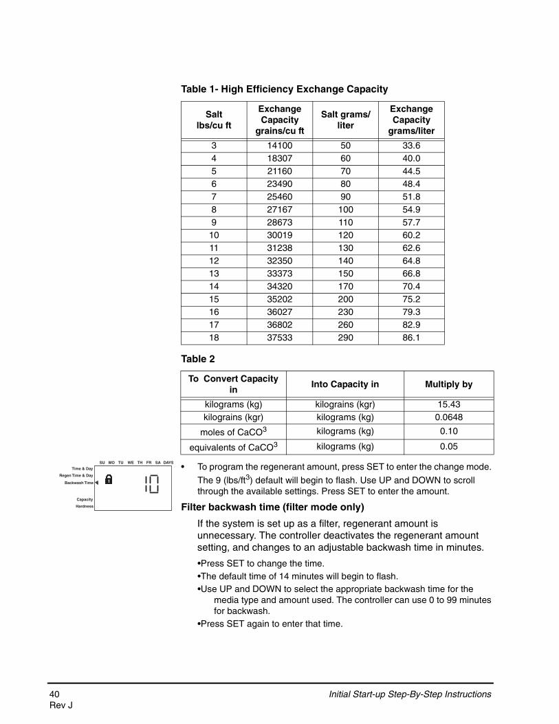
• To program the regenerant amount, press SET to enter the change mode.
The 9 (lbs/ft3) default will begin to flash. Use UP and DOWN to scroll through the available settings. Press SET to enter the amount.
Filter backwash time (filter mode only)
If the system is set up as a filter, regenerant amount is unnecessary. The controller deactivates the regenerant amount setting, and changes to an adjustable backwash time in minutes.
•Press SET to change the time. •The default time of 14 minutes will begin to flash. •Use UP and DOWN to select the appropriate backwash time for the
media type and amount used. The controller can use 0 to 99 minutes for backwash.
•Press SET again to enter that time.
Table 1- High Efficiency Exchange Capacity
Salt lbs/cu ft
Exchange Capacity
grains/cu ft
Salt grams/liter
Exchange Capacity
grams/liter
3 14100 50 33.64 18307 60 40.05 21160 70 44.56 23490 80 48.47 25460 90 51.88 27167 100 54.99 28673 110 57.710 30019 120 60.211 31238 130 62.612 32350 140 64.813 33373 150 66.814 34320 170 70.415 35202 200 75.216 36027 230 79.317 36802 260 82.918 37533 290 86.1
Table 2
To Convert Capacity in
Into Capacity in Multiply by
kilograms (kg) kilograins (kgr) 15.43kilograins (kgr) kilograms (kg) 0.0648
moles of CaCO3 kilograms (kg) 0.10
equivalents of CaCO3 kilograms (kg) 0.05
Time & Day
Regen Time & Day
Backwash Time
SU MO TU WE TH FR SA DAYS
Capacity
Hardness
40 Initial Start-up Step-By-Step InstructionsRev J
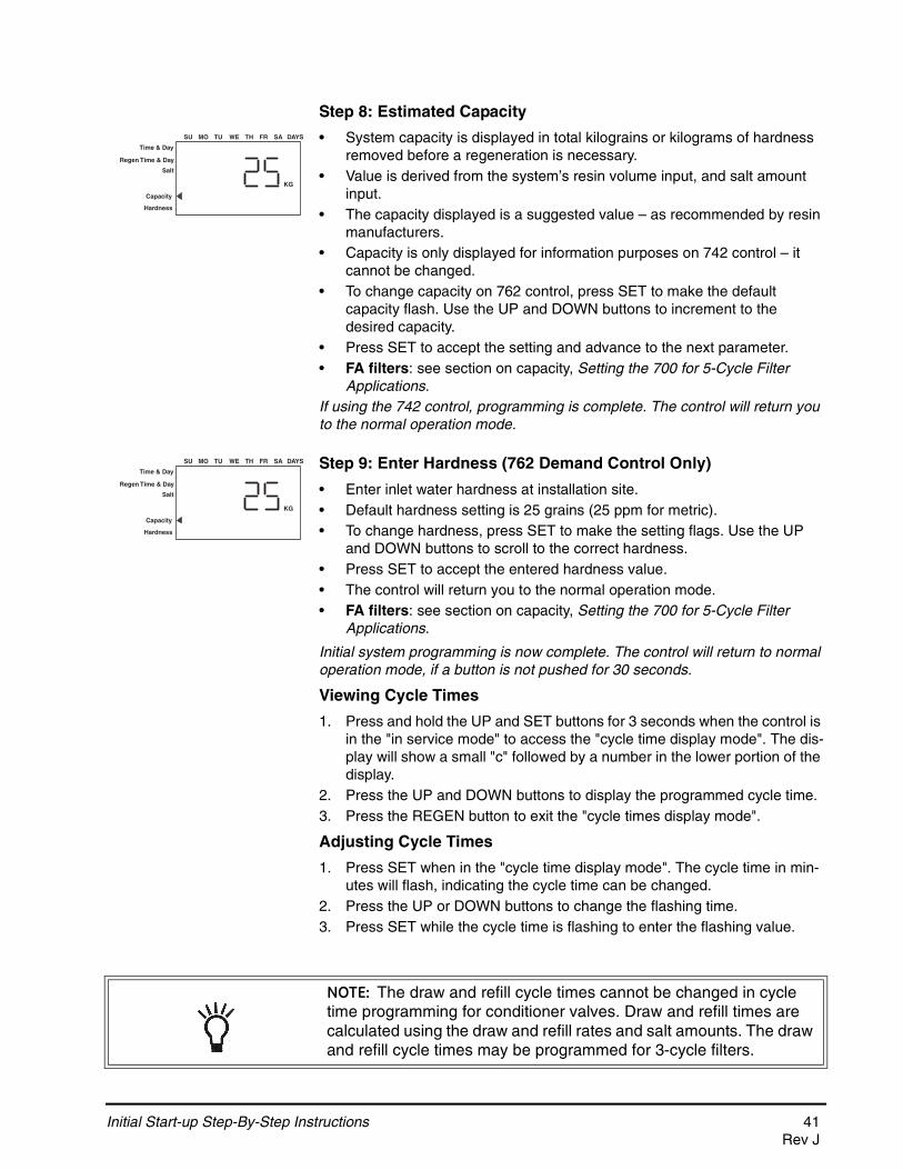
Step 8: Estimated Capacity
• System capacity is displayed in total kilograins or kilograms of hardness removed before a regeneration is necessary.
• Value is derived from the system’s resin volume input, and salt amount input.
• The capacity displayed is a suggested value – as recommended by resin manufacturers.
• Capacity is only displayed for information purposes on 742 control – it cannot be changed.
• To change capacity on 762 control, press SET to make the default capacity flash. Use the UP and DOWN buttons to increment to the desired capacity.
• Press SET to accept the setting and advance to the next parameter.• FA filters: see section on capacity, Setting the 700 for 5-Cycle Filter
Applications.If using the 742 control, programming is complete. The control will return you to the normal operation mode.
Step 9: Enter Hardness (762 Demand Control Only)
• Enter inlet water hardness at installation site.• Default hardness setting is 25 grains (25 ppm for metric).• To change hardness, press SET to make the setting flags. Use the UP
and DOWN buttons to scroll to the correct hardness.• Press SET to accept the entered hardness value.• The control will return you to the normal operation mode.• FA filters: see section on capacity, Setting the 700 for 5-Cycle Filter
Applications.
Initial system programming is now complete. The control will return to normal operation mode, if a button is not pushed for 30 seconds.
Viewing Cycle Times
1. Press and hold the UP and SET buttons for 3 seconds when the control is in the "in service mode" to access the "cycle time display mode". The dis-play will show a small "c" followed by a number in the lower portion of the display.
2. Press the UP and DOWN buttons to display the programmed cycle time.3. Press the REGEN button to exit the "cycle times display mode".
Adjusting Cycle Times
1. Press SET when in the "cycle time display mode". The cycle time in min-utes will flash, indicating the cycle time can be changed.
2. Press the UP or DOWN buttons to change the flashing time.3. Press SET while the cycle time is flashing to enter the flashing value.
KG
Time & Day
Regen Time & Day
Salt
SU MO TU WE TH FR SA DAYS
Capacity
Hardness
KG
Time & Day
Regen Time & Day
Salt
SU MO TU WE TH FR SA DAYS
Capacity
Hardness
NOTE: The draw and refill cycle times cannot be changed in cycle time programming for conditioner valves. Draw and refill times are calculated using the draw and refill rates and salt amounts. The draw and refill cycle times may be programmed for 3-cycle filters.
Initial Start-up Step-By-Step Instructions 41Rev J
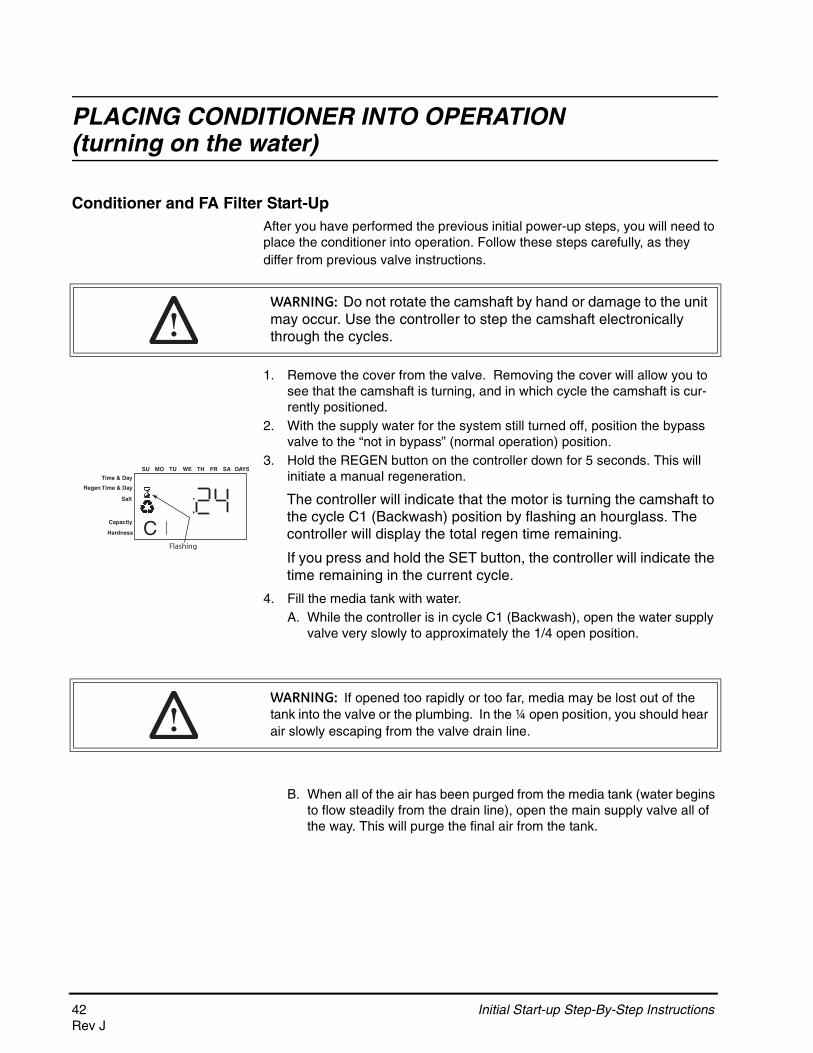
PLACING CONDITIONER INTO OPERATION (turning on the water)
Conditioner and FA Filter Start-UpAfter you have performed the previous initial power-up steps, you will need to place the conditioner into operation. Follow these steps carefully, as they differ from previous valve instructions.
1. Remove the cover from the valve. Removing the cover will allow you to see that the camshaft is turning, and in which cycle the camshaft is cur-rently positioned.
2. With the supply water for the system still turned off, position the bypass valve to the “not in bypass” (normal operation) position.
3. Hold the REGEN button on the controller down for 5 seconds. This will initiate a manual regeneration.
The controller will indicate that the motor is turning the camshaft to the cycle C1 (Backwash) position by flashing an hourglass. The controller will display the total regen time remaining.
If you press and hold the SET button, the controller will indicate the time remaining in the current cycle.
4. Fill the media tank with water.A. While the controller is in cycle C1 (Backwash), open the water supply
valve very slowly to approximately the 1/4 open position.
B. When all of the air has been purged from the media tank (water begins to flow steadily from the drain line), open the main supply valve all of the way. This will purge the final air from the tank.
WARNING: Do not rotate the camshaft by hand or damage to the unit may occur. Use the controller to step the camshaft electronically through the cycles.
Time & Day
Regen Time & Day
Salt
SU MO TU WE TH FR SA DAYS
CCapacity
Hardness
Flashing
WARNING: If opened too rapidly or too far, media may be lost out of the tank into the valve or the plumbing. In the ¼ open position, you should hear air slowly escaping from the valve drain line.
42 Initial Start-up Step-By-Step InstructionsRev J
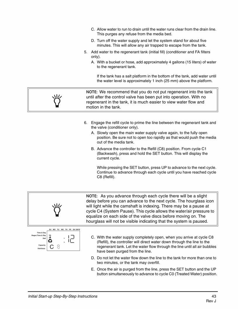
C. Allow water to run to drain until the water runs clear from the drain line. This purges any refuse from the media bed.
D. Turn off the water supply and let the system stand for about five minutes. This will allow any air trapped to escape from the tank.
5. Add water to the regenerant tank (initial fill) (conditioner and FA filters only).A. With a bucket or hose, add approximately 4 gallons (15 liters) of water
to the regenerant tank.
If the tank has a salt platform in the bottom of the tank, add water until the water level is approximately 1 inch (25 mm) above the platform.
6. Engage the refill cycle to prime the line between the regenerant tank and the valve (conditioner only).A. Slowly open the main water supply valve again, to the fully open
position. Be sure not to open too rapidly as that would push the media out of the media tank.
B. Advance the controller to the Refill (C8) position. From cycle C1 (Backwash), press and hold the SET button. This will display the current cycle.
While pressing the SET button, press UP to advance to the next cycle. Continue to advance through each cycle until you have reached cycle C8 (Refill).
C. With the water supply completely open, when you arrive at cycle C8 (Refill), the controller will direct water down through the line to the regenerant tank. Let the water flow through the line until all air bubbles have been purged from the line.
D. Do not let the water flow down the line to the tank for more than one to two minutes, or the tank may overfill.
E. Once the air is purged from the line, press the SET button and the UP button simultaneously to advance to cycle C0 (Treated Water) position.
NOTE: We recommend that you do not put regenerant into the tank until after the control valve has been put into operation. With no regenerant in the tank, it is much easier to view water flow and motion in the tank.
NOTE: As you advance through each cycle there will be a slight delay before you can advance to the next cycle. The hourglass icon will light while the camshaft is indexing. There may be a pause at cycle C4 (System Pause). This cycle allows the water/air pressure to equalize on each side of the valve discs before moving on. The hourglass will not be visible indicating that the system is paused.
Time & Day
Regen Time & Day
Salt
SU MO TU WE TH FR SA DAYS
CCapacity
Hardness
Initial Start-up Step-By-Step Instructions 43Rev J

7. Draw water from the regenerant tank.A. From the treated water position (cycle C0), advance the valve to the
draw regenerant position. Hold the REGEN button down for five seconds.
The controller will begin a manual regen, and advance the control valve to the cycle C1 (Backwash). Press the SET and UP button to advance to cycle C2 (Draw).
B. With the controller in this position, check to see that the water in the regenerant tank is being drawn out of the tank. The water level in the tank should recede very slowly.
C. Observe the water being drawn from the regenerant tank for at least three minutes. If the water level does not recede, or goes up, check all hose connections. C2 should be displayed.
8. If the water level is receding from the regenerant tank you can then advance the controller back to the treated water (C0) position by pressing SET and the UP buttons simultaneously to advance the controller to the C0 position.
9. Finally, turn on a faucet plumbed after the water conditioner. Run the faucet until the water runs clear.
44 Initial Start-up Step-By-Step InstructionsRev J
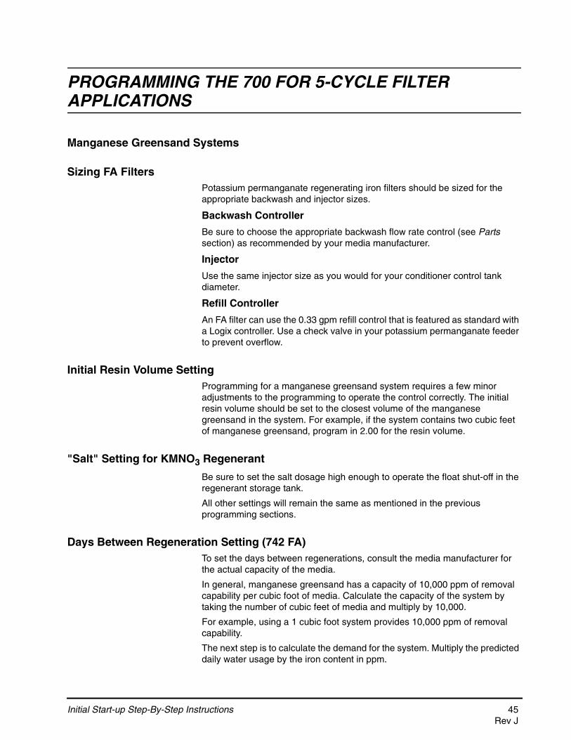
PROGRAMMING THE 700 FOR 5-CYCLE FILTER APPLICATIONS
Manganese Greensand Systems
Sizing FA FiltersPotassium permanganate regenerating iron filters should be sized for the appropriate backwash and injector sizes.
Backwash Controller
Be sure to choose the appropriate backwash flow rate control (see Parts section) as recommended by your media manufacturer.
Injector
Use the same injector size as you would for your conditioner control tank diameter.
Refill Controller
An FA filter can use the 0.33 gpm refill control that is featured as standard with a Logix controller. Use a check valve in your potassium permanganate feeder to prevent overflow.
Initial Resin Volume SettingProgramming for a manganese greensand system requires a few minor adjustments to the programming to operate the control correctly. The initial resin volume should be set to the closest volume of the manganese greensand in the system. For example, if the system contains two cubic feet of manganese greensand, program in 2.00 for the resin volume.
"Salt" Setting for KMNO3 Regenerant
Be sure to set the salt dosage high enough to operate the float shut-off in the regenerant storage tank.
All other settings will remain the same as mentioned in the previous programming sections.
Days Between Regeneration Setting (742 FA)To set the days between regenerations, consult the media manufacturer for the actual capacity of the media.
In general, manganese greensand has a capacity of 10,000 ppm of removal capability per cubic foot of media. Calculate the capacity of the system by taking the number of cubic feet of media and multiply by 10,000.
For example, using a 1 cubic foot system provides 10,000 ppm of removal capability.
The next step is to calculate the demand for the system. Multiply the predicted daily water usage by the iron content in ppm.
Initial Start-up Step-By-Step Instructions 45Rev J
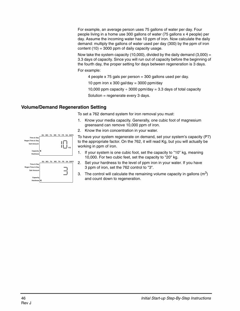
For example, an average person uses 75 gallons of water per day. Four people living in a home use 300 gallons of water (75 gallons x 4 people) per day. Assume the incoming water has 10 ppm of iron. Now calculate the daily demand: multiply the gallons of water used per day (300) by the ppm of iron content (10) = 3000 ppm of daily capacity usage.
Now take the system capacity (10,000), divided by the daily demand (3,000) = 3.3 days of capacity. Since you will run out of capacity before the beginning of the fourth day, the proper setting for days between regeneration is 3 days.
For example:
4 people x 75 gals per person = 300 gallons used per day.
10 ppm iron x 300 gal/day = 3000 ppm/day
10,000 ppm capacity 3000 ppm/day = 3.3 days of total capacity
Solution = regenerate every 3 days.
Volume/Demand Regeneration SettingTo set a 762 demand system for iron removal you must:
1. Know your media capacity. Generally, one cubic foot of magnesium greensand can remove 10,000 ppm of iron.
2. Know the iron concentration in your water.
To have your system regenerate on demand, set your system’s capacity (P7) to the appropriate factor. On the 762, it will read Kg, but you will actually be working in ppm of iron.
1. If your system is one cubic foot, set the capacity to "10" kg, meaning 10,000. For two cubic feet, set the capacity to "20" kg.
2. Set your hardness to the level of ppm iron in your water. If you have 3 ppm of iron, set the 762 control to "3".
3. The control will calculate the remaining volume capacity in gallons (m3) and count down to regeneration.
Time & Day
Regen Time & Day
Salt Amount
SU MO TU WE TH FR SA DAYS
Capacity
Hardness
KG
Time & Day
Regen Time & Day
Salt Amount
SU MO TU WE TH FR SA DAYS
Capacity
Hardness
46 Initial Start-up Step-By-Step InstructionsRev J
Things You Might Need to Know
• When the controller is first plugged in, it may display a flashing hourglass and the message Err 3, this means that the controller is rotating to the home position. If the Err 2 is displayed, check that the incoming power frequency matches the controller. The North American controller will not run with 50 Hz input.
• The preset default time of regeneration is 2:00 AM. • English or Metric? The World controller senses the electrical input and
decides which is needed. The North American controller only runs on 60 Hz and defaults to English units.
• The 700 Series controller can be programmed to regenerate on specific days of the week.
• If electrical power is not available, the camshaft can be rotated counterclockwise by hand if the motor is removed.
• The 700 Series controllers send commands to the motor for camshaft movement. However, water pressure/flow are required during the regeneration cycle for backwash, purge and refill, and brine draw to actually take place.
• Make sure control power source is plugged in. The transformer should be connected to a non-switched power source.
• You can start programming at the beginning by resetting the amount of media. When viewing H0 (History Value) push and hold SET for five seconds. The display reverts back to --- and any programmed information is lost. Return to 700 Series Initial Power Up.
Initial Start-up Step-By-Step Instructions 47Rev J
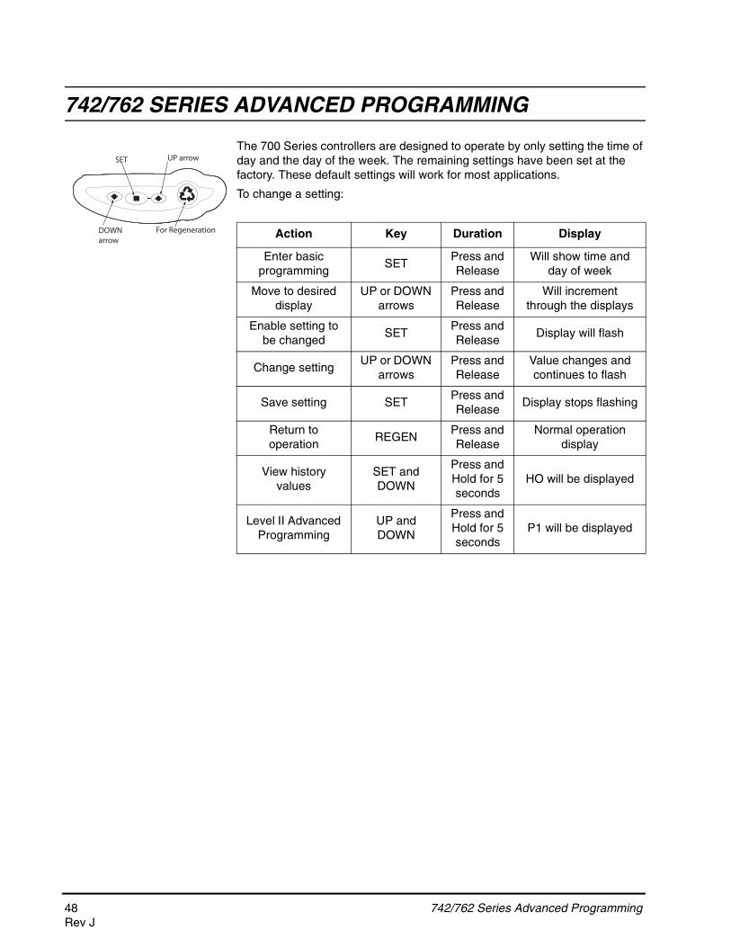
742/762 SERIES ADVANCED PROGRAMMING
The 700 Series controllers are designed to operate by only setting the time of day and the day of the week. The remaining settings have been set at the factory. These default settings will work for most applications.
To change a setting:
742/762 Series Advanced Programming
Action Key Duration Display
Enter basic programming
SETPress and Release
Will show time and day of week
Move to desired display
UP or DOWN arrows
Press and Release
Will increment through the displays
Enable setting to be changed
SETPress and Release
Display will flash
Change setting UP or DOWN
arrowsPress and Release
Value changes and continues to flash
Save setting SETPress and Release
Display stops flashing
Return to operation
REGENPress and Release
Normal operation display
View history values
SET and DOWN
Press and Hold for 5 seconds
HO will be displayed
Level II Advanced Programming
UP and DOWN
Press and Hold for 5 seconds
P1 will be displayed
For Regeneration
SET UP arrow
DOWNarrow
48 742/762 Series Advanced ProgrammingRev J

742/762 Level II Professional ProgrammingThe 742/762 features a special programming level that allows the installing dealer to make changes to the control for more demanding applications. The home owner/end user should never have to access this level.
To enter Level II programming press and hold UP and DOWN for 5 seconds. A "P" value will be displayed indicating Level II.
Level II menus include:
P1 = Time of day
P2 = Day of week
P3 = Time of regeneration
P4 = Number of days between regeneration (99 day calendar override)
P5 = Not used (742 only)
P6 = Amount of regenerant used per regeneration or filter backwash time (salt setting)
P7 = System capacity
P8 = Hardness
P9 = Units of measure
P10 = Clock mode
P11 = Service interval
P12 = Remote regeneration switch delay
P13 = Refill sensor control (conditioner only)
0 = Off1 = Salt detector only2 = Chlorine generation
P14 = Refill rate (conditioner only)
P15 = Draw rate (conditioner only)
P16 = Reserve type
P17 = Initial average or fixed reserve
P18 = Flow sensor select
P19 = K-factor or pulse equivalent
Pr = Refill First option
Pd = Remote switch operation (742 only)
See the Logix Professional dealers manual for further details on setting Level II parameters.
Time & Day
Regen Time & Day
Salt Amount
SU MO TU WE TH FR SA DAYS
PCapacity
Hardness
P Value
742/762 Level II Professional Programming 49Rev J
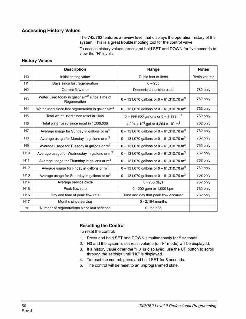
Accessing History ValuesThe 742/762 features a review level that displays the operation history of the system. This is a great troubleshooting tool for the control valve.
To access history values, press and hold SET and DOWN for five seconds to view the "H" levels.
History Values
Resetting the ControlTo reset the control:
1. Press and hold SET and DOWN simultaneously for 5 seconds.2. H0 and the system’s set resin volume (or “F” mode) will be displayed.3. If a history value other the “H0” is displayed, use the UP button to scroll
through the settings until “H0” is displayed.4. To reset the control, press and hold SET for 5 seconds.5. The control will be reset to an unprogrammed state.
Description Range Notes
H0 Initial setting value Cubic feet or liters Resin volume
H1 Days since last regeneration 0 – 255
H2 Current flow rate Depends on turbine used 762 only
H3 Water used today in gallons/m3 since Time of Regeneration
0 – 131,070 gallons or 0 – 61,310.70 m3 762 only
H4 Water used since last regeneration in gallons/m3 0 – 131,070 gallons or 0 – 61,310.70 m3 762 only
H5 Total water used since reset in 100s 0 – 999,900 gallons or 0 – 9,999 m3 762 only
H6 Total water used since reset in 1,000,000 4,294 x 106 gal or 4,264 x 104 m3 762 only
H7 Average usage for Sunday in gallons or m3 0 – 131,070 gallons or 0 – 61,310.70 m3 762 only
H8 Average usage for Monday in gallons or m3 0 – 131,070 gallons or 0 – 61,310.70 m3 762 only
H9 Average usage for Tuesday in gallons or m3 0 – 131,070 gallons or 0 – 61,310.70 m3 762 only
H10 Average usage for Wednesday in gallons or m3 0 – 131,070 gallons or 0 – 61,310.70 m3 762 only
H11 Average usage for Thursday in gallons or m3 0 – 131,070 gallons or 0 – 61,310.70 m3 762 only
H12 Average usage for Friday in gallons or m3 0 – 131,070 gallons or 0 – 61,310.70 m3 762 only
H13 Average usage for Saturday in gallons or m3 0 – 131,070 gallons or 0 – 61,310.70 m3 762 only
H14 Average service cycle 0 - 255 days 762 only
H15 Peak flow rate 0 - 200 gpm or 1,000 Lpm 762 only
H16 Day and time of peak flow rate Time and day that peak flow occurred 762 only
H17 Months since service 0 - 2,184 months
Hr Number of regenerations since last serviced 0 - 65,536
50 742/762 Level II Professional ProgrammingRev J
6. Go to “Initial Set-up” section to reprogram control.
All further advance programming or set-up instructions can be found in the Dealer Installation and Service Manual, P/N 1255652.
WARNING: Resetting the control will delete all information stored in its memory, except time and day. This will require you to reprogram the control completely from the initial power-up mode.
742/762 Level II Professional Programming 51Rev J

PARTS AND ACCESSORIES
255 Valve Exploded View
1
2
3
4
5
6
7
8
9
11
12
14
15
16
10
18A*
20
13
17
19
13
18B
*Warning: Do not use flow control ball with #18A.
21
21
22
52 255 Valve Exploded ViewRev J

255 Valve Parts List
*Not Shown
Code
Part
No. Description Qty. Code
Part
No. Description Qty.1 1244650 255 Valve Assembly, w/o Flow Controls 1 16 1000269 Injector Cap with O-Ring 1
2 1033784 255 Tank Adapter New Style 1 17 Drain Control Assembly with O-Ring 1
3 1010429 O-Ring BN 1 1000209 No. 7 (1.3 gpm; 4.9 Lpm)
4 1010428 O-Ring EP 1000210 No. 8 (1.7 gpm; 6.4 Lpm)
5 1235340 Top Plate, 255 Valve, 700/860 Series 1 1000211 No. 9 (2.2 gpm; 8.3 Lpm)
Controller 1000212 No. 10 (2.7 gpm; 10.2 Lpm)
6 1235341 Spring, One Piece, 255 Valve 1 1002130 No. 12 (3.9 gpm; 14.76 Lpm)
7 1236246* Cover, Valve, 255/Performa, 700/860 1 1000214 No. 13 (4.5 gpm; 17 Lpm)
Series Controller 1000215 No. 14 (5.3 gpm; 20 Lpm)
8 1001404 O-Ring Group: Tank Adapter 1 18A 1000222 Regenerant Refill Controller, No Ball, 0.33 gal. 1
9 1040459 O-Ring Group: Piping Boss 1 18B 1243510 Regenerant Refill Controller
10 1001986 13/16 inch Rubber Insert (Optional) 1 19 Air Check Kit 1
* 1000250 Valve Disk Kit - Standard 1 1032416 Air Check Kit 3/8-inch male
* 1239760 Blending Valve Kit 900/700 Series 1 1032417 Air Check Kit 1/4-inch male
11 Locking Bar 1 20 1235373 Module, Sensor, Photo Interrupter 1
1031402 English Language Locking Bar 21 1030502 Ball, Flow Control 1
1031403 French Language Locking Bar * 1033066 New to Old Style Aircheck Adapter 1
1031404 German Language Locking Bar 22 1235446 Turbine Cable 1
1031405 Italian Language Locking/Bar * 1233187 Motor Locking Pin
1031406 Japanese Language Locking Bar * 1244336 Chlorine Generator Kit, 0.33 gpm
1031407 Spanish Language Locking Bar * 1242411 Extension Cord for Cabinet
1006093 Locking Bar Screw - No. 8-9/16 inch * 1239711 Service Kit, Front Mount, 0.1 amp
12 Camshaft Options 1 * 1239752 Service Kit, Front Mount, 5 amp
1235353 Cam 255/700-860 Series Valve, STD, * 1239753 Service Kit, Top Plate Mount, 0.1 amp
Black * 1239754 Service Kit, Top Plate Mount, 5 amp
1236251 Cam 255/700-860 Series Valve, TWIN,
Tan (insert)
13 1235361 Motor/Optical Cable Assembly 1
14 1000226 Screen/Cap Assembly w/ O-Ring 1
15 Injector (High Efficiency) Options 1
1035730 “E” Injector (HIgh Efficiency) - Yellow
(6-inch tank)
1035731 “F” Injector (High Efficiency) - Peach
(7-inch tank)
1035732 “G” Injector (High Efficiency) - Tan
(8-inch tank)
1035733 “H” Injector (High Efficiency) - Lt Purple
(9-inch tank)
1035734 “J” Injector (High Efficiency) - Lt Blue
(10-inch tank)
1035735 “K” Injector (High Efficiency) - Pink
(12-inch tank)
1035736 “L” Injector (High Efficiency) - Orange
(13 - 14-inch tank)
255 Valve Parts List 53Rev J

255 Valve Parts List (Continued)
*Not Shown
Code
Part
No. Description Qty. Code
Part
No. Description Qty.* Piping Boss Tube Adapter Kits
Piping Boss Kit (includes hardware): * 1001606 3/4-inch Copper Tube Adapter Kit 1
1040277 3/4-inch NPT, Brass 3/8-inch NPT Drain * 1001670 1-inch Copper Tube Adapter Kit 1
1040278 1-inch NPT, Brass 1/2-inch NPT Drain * 1001608 22-mm Copper Tube Adapter Kit 1
1040281 3/4-inch BSPT, Brass 3/8-inch BSPT * 1001613 3/4-inch CPVC Tube Adapter Kit 1
Drain * 1001614 1-inch CPVC Tube Adapter Kit 1
1040282 1-inch BSPT, Brass 1/2-inch BSPT Drain * 1001615 25-mm CPVC Tube Adapter Kit 1
1040279 3/4-inch NPT, Plastic 1/2-inch NPT Drain * 1001769 3/4-inch NPT Plastic Pipe Adapter Kit 1
1040280 1-inch NPT, Plastic 1/2-inch NPT Drain * 1001603 1-inch NPT Plastic Pipe Adapter Kit 1
1040283 3/4-inch BSPT, Plastic 1/2-inch BSPT * 1001604 3/4-inch BSPT Plastic Pipe Adapter Kit 1
Drain * 1001605 1-inch BSPT Plastic Pipe Adapter Kit 1
1040284 1-inch BSPT, Plastic 1/2-inch BSPT Drain
* 1001611 3/4-inch BSPT Brass Pipe Adapter Kit 1
* 1040339 Piping Boss Installation Kit 1 * 1001610 1-inch NPT Brass Pipe Adapter Kit 1
* Meter Adapter * 1001612 1-inch BSPT Brass Pipe Adapter Kit 1
1032350 Kit, Meter Adapter 1
1032351 Meter Install Kit 1
* Bypass Valve
1040769 Bypass Body Assembly with Install Kit 1
1040524 Bypass Installation Kit 1
54 255 Valve Parts ListRev J
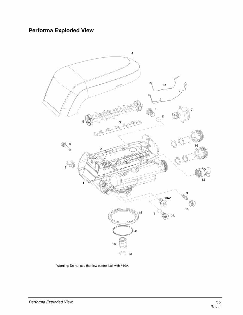
Performa Exploded View
2
1
3
4
5
6
7
8
9
10A*
11
12
13
14
16
17
7
15
18
10B11
*Warning: Do not use the flow control ball with #10A.
19
20
Performa Exploded View 55Rev J
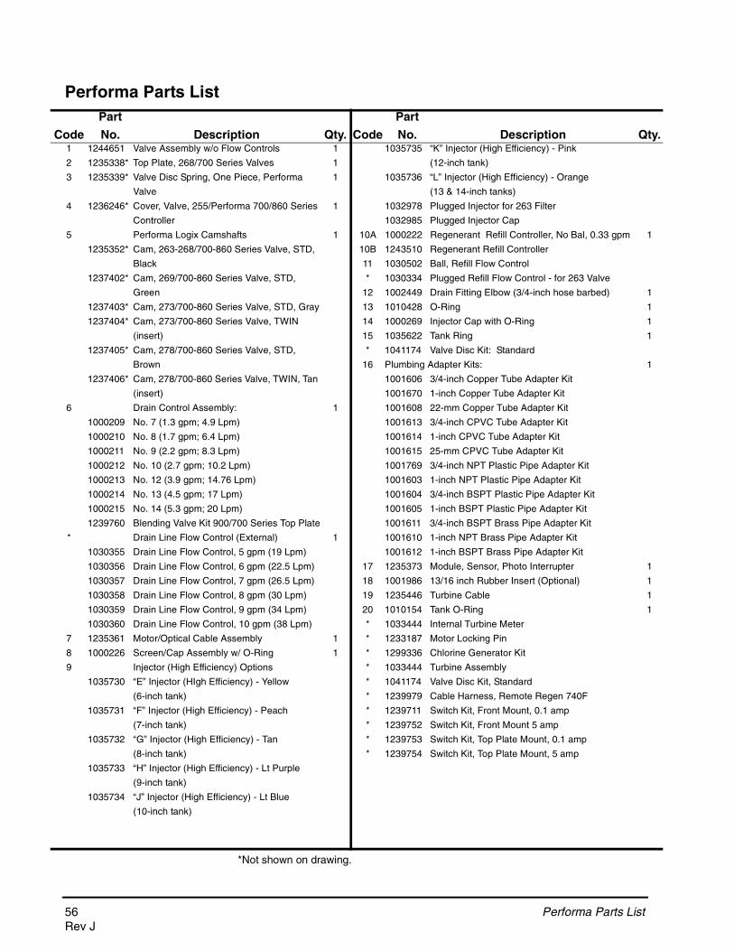
C
Performa Parts List
*Not shown on drawing.
ode
Part
No. Description Qty. Code
Part
No. Description Qty.1 1244651 Valve Assembly w/o Flow Controls 1 1035735 “K” Injector (High Efficiency) - Pink
2 1235338* Top Plate, 268/700 Series Valves 1 (12-inch tank)
3 1235339* Valve Disc Spring, One Piece, Performa 1 1035736 “L” Injector (High Efficiency) - Orange
Valve (13 & 14-inch tanks)
4 1236246* Cover, Valve, 255/Performa 700/860 Series 1 1032978 Plugged Injector for 263 Filter
Controller 1032985 Plugged Injector Cap
5 Performa Logix Camshafts 1 10A 1000222 Regenerant Refill Controller, No Bal, 0.33 gpm 1
1235352* Cam, 263-268/700-860 Series Valve, STD, 10B 1243510 Regenerant Refill Controller
Black 11 1030502 Ball, Refill Flow Control
1237402* Cam, 269/700-860 Series Valve, STD, * 1030334 Plugged Refill Flow Control - for 263 Valve
Green 12 1002449 Drain Fitting Elbow (3/4-inch hose barbed) 1
1237403* Cam, 273/700-860 Series Valve, STD, Gray 13 1010428 O-Ring 1
1237404* Cam, 273/700-860 Series Valve, TWIN 14 1000269 Injector Cap with O-Ring 1
(insert) 15 1035622 Tank Ring 1
1237405* Cam, 278/700-860 Series Valve, STD, * 1041174 Valve Disc Kit: Standard
Brown 16 Plumbing Adapter Kits: 1
1237406* Cam, 278/700-860 Series Valve, TWIN, Tan 1001606 3/4-inch Copper Tube Adapter Kit
(insert) 1001670 1-inch Copper Tube Adapter Kit
6 Drain Control Assembly: 1 1001608 22-mm Copper Tube Adapter Kit
1000209 No. 7 (1.3 gpm; 4.9 Lpm) 1001613 3/4-inch CPVC Tube Adapter Kit
1000210 No. 8 (1.7 gpm; 6.4 Lpm) 1001614 1-inch CPVC Tube Adapter Kit
1000211 No. 9 (2.2 gpm; 8.3 Lpm) 1001615 25-mm CPVC Tube Adapter Kit
1000212 No. 10 (2.7 gpm; 10.2 Lpm) 1001769 3/4-inch NPT Plastic Pipe Adapter Kit
1000213 No. 12 (3.9 gpm; 14.76 Lpm) 1001603 1-inch NPT Plastic Pipe Adapter Kit
1000214 No. 13 (4.5 gpm; 17 Lpm) 1001604 3/4-inch BSPT Plastic Pipe Adapter Kit
1000215 No. 14 (5.3 gpm; 20 Lpm) 1001605 1-inch BSPT Plastic Pipe Adapter Kit
1239760 Blending Valve Kit 900/700 Series Top Plate 1001611 3/4-inch BSPT Brass Pipe Adapter Kit
* Drain Line Flow Control (External) 1 1001610 1-inch NPT Brass Pipe Adapter Kit
1030355 Drain Line Flow Control, 5 gpm (19 Lpm) 1001612 1-inch BSPT Brass Pipe Adapter Kit
1030356 Drain Line Flow Control, 6 gpm (22.5 Lpm) 17 1235373 Module, Sensor, Photo Interrupter 1
1030357 Drain Line Flow Control, 7 gpm (26.5 Lpm) 18 1001986 13/16 inch Rubber Insert (Optional) 1
1030358 Drain Line Flow Control, 8 gpm (30 Lpm) 19 1235446 Turbine Cable 1
1030359 Drain Line Flow Control, 9 gpm (34 Lpm) 20 1010154 Tank O-Ring 1
1030360 Drain Line Flow Control, 10 gpm (38 Lpm) * 1033444 Internal Turbine Meter
7 1235361 Motor/Optical Cable Assembly 1 * 1233187 Motor Locking Pin
8 1000226 Screen/Cap Assembly w/ O-Ring 1 * 1299336 Chlorine Generator Kit
9 Injector (High Efficiency) Options * 1033444 Turbine Assembly
1035730 “E” Injector (HIgh Efficiency) - Yellow * 1041174 Valve Disc Kit, Standard
(6-inch tank) * 1239979 Cable Harness, Remote Regen 740F
1035731 “F” Injector (High Efficiency) - Peach * 1239711 Switch Kit, Front Mount, 0.1 amp
(7-inch tank) * 1239752 Switch Kit, Front Mount 5 amp
1035732 “G” Injector (High Efficiency) - Tan * 1239753 Switch Kit, Top Plate Mount, 0.1 amp
(8-inch tank) * 1239754 Switch Kit, Top Plate Mount, 5 amp
1035733 “H” Injector (High Efficiency) - Lt Purple
(9-inch tank)
1035734 “J” Injector (High Efficiency) - Lt Blue
(10-inch tank)
56 Performa Parts ListRev J

Logix 700 Series Controllers Parts List
742/762 Control
Time & Day
Regen Time & Day
Salt
SU MO TU WE TH FR SA DAYS
LBS
PMMIN
KG
x100x2
PHC
Capacity
Hardness
AC Adapter
Time/Day
Su Mo Tu We Th Fr Sa DAYS
Regeneration Time/DaySalt Amount
700 Control Overlays
Code
Part
No. Description Qty. Code
Part
No. Description Qty.Electronics Modules/Controllers 1 AC Adapter
1242150 Logix 742 Controller 1000810 Japanese
1242162 Logix 742 F Controller 1000811 North American
1242168 Logix 762 Controller 1000812 Australian
1242170 Logix 762F Controller 1000813 British
Electrical Components 1000814 European
1235373 Module, Sensor, Photo Interrupter 1030234 Transformer Extension Cord 15 foot (4.5m)
1235361 Motor w/Spacer & Pinion, 700 Series 1235448 North American Outdoor AC Adapter
Controller 12V, 50/60 Hz Overlays
1244336 Refill Sensor Probe for Salt Detector 1238472 Overlay, 716 Controller, English
Applications 1238476 Overlay, 740C/742C Controller, English
1256257 Remote Mount Kit
Logix 700 Series Controllers Parts List 57Rev J
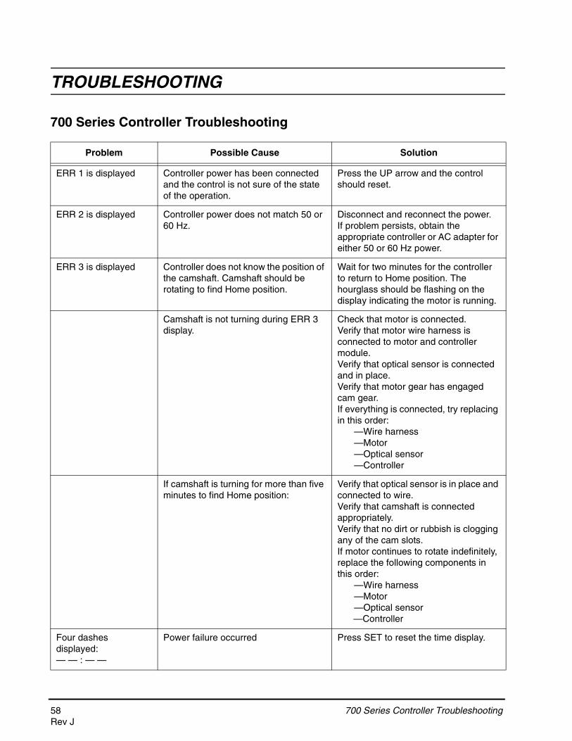
TROUBLESHOOTING
700 Series Controller Troubleshooting
Problem Possible Cause Solution
ERR 1 is displayed Controller power has been connected and the control is not sure of the state of the operation.
Press the UP arrow and the control should reset.
ERR 2 is displayed Controller power does not match 50 or 60 Hz.
Disconnect and reconnect the power.If problem persists, obtain the appropriate controller or AC adapter for either 50 or 60 Hz power.
ERR 3 is displayed Controller does not know the position of the camshaft. Camshaft should be rotating to find Home position.
Wait for two minutes for the controller to return to Home position. The hourglass should be flashing on the display indicating the motor is running.
Camshaft is not turning during ERR 3 display.
Check that motor is connected.Verify that motor wire harness is connected to motor and controller module.Verify that optical sensor is connected and in place. Verify that motor gear has engaged cam gear.If everything is connected, try replacing in this order:
—Wire harness—Motor—Optical sensor—Controller
If camshaft is turning for more than five minutes to find Home position:
Verify that optical sensor is in place and connected to wire.Verify that camshaft is connected appropriately.Verify that no dirt or rubbish is clogging any of the cam slots.If motor continues to rotate indefinitely, replace the following components in this order:
—Wire harness—Motor—Optical sensor—Controller
Four dashes displayed:— — : — —
Power failure occurred Press SET to reset the time display.
58 700 Series Controller TroubleshootingRev J

System TroubleshootingProblem Possible Cause Solution
1. Brine tank overflow.
a. Uncontrolled brine refill flow rate.
b. Air leak in brine line to air check.
c. Drain control clogged with resin or other debris.
a. Remove brine control to clean ball and seat.
b. Check all connections in brine line for leaks. Refer to instructions.
c. Clean drain control.
2. Flowing or dripping water at drain or brine line after regeneration.
a. Valve stem return spring weak.b. Debris is preventing valve disc
from closing.
a. Replace spring. (Contact dealer.)b. Remove debris.
3. Hard water leakage after regeneration.
a. Improper regeneration.
b. Leaking of external bypass valve.
c. O-ring around riser pipe damaged.
d. Incorrect capacity.
a. Repeat regeneration after making certain correct salt dosage was set.
b. Replace bypass valve. (Contact dealer.)
c. Replace O-ring. (Contact dealer.)
d. Verify appropriate salt amount and system capacity. (Contact dealer.)
4. Control will not draw brine.
a. Low water pressure.
b. Restricted drain line.c. Injector plugged.d. Injector defective.
e. Valve disc 2 and/or 3 not closed.
f. Air check valve prematurely closed.
a. Make correct setting according to instructions.
b. Remove restriction.c. Clean injector and screen.d. Replace injector and cap. (Contact
dealer.)e. Remove foreign matter from disc and
check disc for closing by pushing in on stem. Replace if needed. (Contact dealer.)
f. Put control momentarily into brine refill, C8. Replace or repair air check if needed. (Contact dealer.)
5. Control will not regenerate automatically.
a. AC adapter or motor not connected.
b. Defective motor.
a. Connect power.
b. Replace motor. (Contact dealer.)6. Control
regenerates at wrong time of day.
a. Controller set incorrectly. a. Correct time setting according to instructions.
7. Valve will not draw brine.
a. Low water pressure.b. Restricted drain line.c. Injector plugged.d. Injector defective.e. Air check valve closes
prematurely on 255 valve or brine pickup tube.
a. Set pump to maintain 20 psi at softener.b. Change drain to remove restriction.c. Clean injector and screen.d. Replace injector. (Contact dealer.)e. Put control momentarily into brine/slow
rinse, C2. Replace or repair air check if needed. (Contact dealer.)
700 Series Controller Troubleshooting 59Rev J
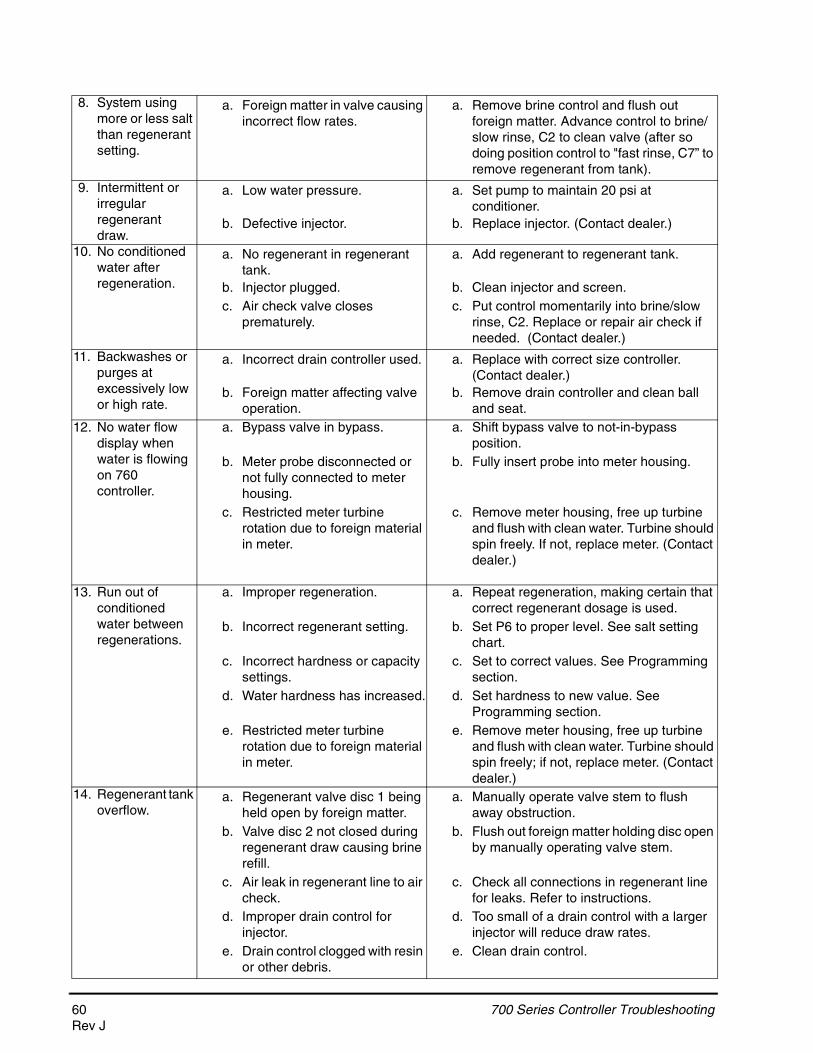
8. System using more or less salt than regenerant setting.
a. Foreign matter in valve causing incorrect flow rates.
a. Remove brine control and flush out foreign matter. Advance control to brine/slow rinse, C2 to clean valve (after so doing position control to "fast rinse, C7” to remove regenerant from tank).
9. Intermittent or irregular regenerant draw.
a. Low water pressure.
b. Defective injector.
a. Set pump to maintain 20 psi at conditioner.
b. Replace injector. (Contact dealer.)
10. No conditioned water after regeneration.
a. No regenerant in regenerant tank.
b. Injector plugged.c. Air check valve closes
prematurely.
a. Add regenerant to regenerant tank.
b. Clean injector and screen.c. Put control momentarily into brine/slow
rinse, C2. Replace or repair air check if needed. (Contact dealer.)
11. Backwashes or purges at excessively low or high rate.
a. Incorrect drain controller used.
b. Foreign matter affecting valve operation.
a. Replace with correct size controller. (Contact dealer.)
b. Remove drain controller and clean ball and seat.
12. No water flow display when water is flowing on 760 controller.
a. Bypass valve in bypass.
b. Meter probe disconnected or not fully connected to meter housing.
c. Restricted meter turbine rotation due to foreign material in meter.
a. Shift bypass valve to not-in-bypass position.
b. Fully insert probe into meter housing.
c. Remove meter housing, free up turbine and flush with clean water. Turbine should spin freely. If not, replace meter. (Contact dealer.)
13. Run out of conditioned water between regenerations.
a. Improper regeneration.
b. Incorrect regenerant setting.
c. Incorrect hardness or capacity settings.
d. Water hardness has increased.
e. Restricted meter turbine rotation due to foreign material in meter.
a. Repeat regeneration, making certain that correct regenerant dosage is used.
b. Set P6 to proper level. See salt setting chart.
c. Set to correct values. See Programming section.
d. Set hardness to new value. See Programming section.
e. Remove meter housing, free up turbine and flush with clean water. Turbine should spin freely; if not, replace meter. (Contact dealer.)
14. Regenerant tank overflow.
a. Regenerant valve disc 1 being held open by foreign matter.
b. Valve disc 2 not closed during regenerant draw causing brine refill.
c. Air leak in regenerant line to air check.
d. Improper drain control for injector.
e. Drain control clogged with resin or other debris.
a. Manually operate valve stem to flush away obstruction.
b. Flush out foreign matter holding disc open by manually operating valve stem.
c. Check all connections in regenerant line for leaks. Refer to instructions.
d. Too small of a drain control with a larger injector will reduce draw rates.
e. Clean drain control.
60 700 Series Controller TroubleshootingRev J

700 Series Controller Troubleshooting 61Rev J

62 700 Series Controller TroubleshootingRev J

700 Series Controller Troubleshooting 63Rev J

© 2011 Pentair Residential Filtration, LLCP/N 3000440 Rev. J JE11