
733 Tech Manual
92
Product Manual 26344 (Revision C) Original Instructions RESTRICTED—NOT FOR GENERAL DISTRIBUTION 733 and 766 Digital Controls Installation Manual
-
Upload
metalshock -
Category
Documents
-
view
214 -
download
13
description
Woodward 733 Digital Controller
Transcript of 733 Tech Manual

Product Manual 26344(Revision C)
Original Instructions
RESTRICTED—NOT FOR GENERAL DISTRIBUTION
733 and 766 Digital Controls
Installation Manual

DEFINITIONS
This is the safety alert symbol. It is used to alert you to potential personal injury hazards. Obey all safety messages that follow this symbol to avoid possible injury or death.
DANGER—Indicates a hazardous situation which, if not avoided, will result in death or serious injury.
WARNING—Indicates a hazardous situation which, if not avoided, could result in death or serious injury.
CAUTION—Indicates a hazardous situation which, if not avoided, could result in minor or moderate injury.
NOTICE—Indicates a hazard that could result in property damage only (including damage to the control).
IMPORTANT—Designates an operating tip or maintenance suggestion.
The engine, turbine, or other type of prime mover should be equipped with an overspeed shutdown device to protect against runaway or damage to the prime mover with possible personal injury, loss of life, or property damage.
The overspeed shutdown device must be totally independent of the prime mover control system. An overtemperature or overpressure shutdown device may also be needed for safety, as appropriate.
Read this entire manual and all other publications pertaining to the work to be performed before installing, operating, or servicing this equipment. Practice all plant and safety instructions and precautions. Failure to follow instructions can cause personal injury and/or property damage.
This publication may have been revised or updated since this copy was produced. To verify that you have the latest revision, be sure to check the publications page on the Woodward website:
www.woodward.com/searchpublications.aspx The current revision of all publications is shown in file "current.pdf". The latest version of most publications is available on the publications page. If your publication is not there, please contact your customer service representative to get the latest copy.
Any unauthorized modifications to or use of this equipment outside its specified mechanical, electrical, or other operating limits may cause personal injury and/or property damage, including damage to the equipment. Any such unauthorized modifications: (i) constitute "misuse" and/or "negligence" within the meaning of the product warranty thereby excluding warranty coverage for any resulting damage, and (ii) invalidate product certifications or listings.
To prevent damage to a control system that uses an alternator or battery-charging device, make sure the charging device is turned off before disconnecting the battery from the system.
To prevent damage to electronic components caused by improper handling, read and observe the precautions in Woodward manual 82715, Guide for Handling and Protection of Electronic Controls, Printed Circuit Boards, and Modules.
Revisions—Text changes are indicated by a black line alongside the text. Woodward reserves the right to update any portion of this publication at any time. Information provided by Woodward is believed to be correct and reliable. However, no responsibility is assumed by Woodward unless otherwise expressly undertaken.
© Woodward 2006 All Rights Reserved

Manual 26344 733 & 766 Digital Controls
Woodward i
Contents
REGULATORY COMPLIANCE ........................................................................ V
ELECTROSTATIC DISCHARGE AWARENESS .................................................VII
CHAPTER 1. GENERAL INFORMATION ........................................................... 1 Introduction ............................................................................................................. 1 Input/Output Arrangement ...................................................................................... 1 Control Specifications ............................................................................................. 2
CHAPTER 2. INSTALLATION.......................................................................... 5 Introduction ............................................................................................................. 5 Unpacking the Shipping Carton .............................................................................. 5 General Installation Notes and Warnings ............................................................... 5 On-Engine Mounting ............................................................................................... 6 Off-Engine Mounting ............................................................................................... 7 Temperature Specifications .................................................................................... 9 Electrical Connections ............................................................................................ 9 Grounding for Protection Against Electrical Shock .............................................. 10 Grounding for Protection Against Electrical Noise ............................................... 11 733 Wiring Diagrams ............................................................................................ 13 Input Power .......................................................................................................... 16 MPU and Proximity Sensor Inputs ....................................................................... 19 Analog Inputs ........................................................................................................ 23 Actuator Output #1 ............................................................................................... 25 Actuator Output #2 ............................................................................................... 27 Analog Outputs ..................................................................................................... 29 Boolean and Frequency Inputs ............................................................................ 30 Boolean Inputs ...................................................................................................... 35 Boolean and PWM Outputs .................................................................................. 37 Serial Communication Ports ................................................................................. 41 CAN Communication Ports................................................................................... 47
CHAPTER 3. SERIAL COMMUNICATIONS ..................................................... 54 Modbus Communication ....................................................................................... 54 Port Adjustments .................................................................................................. 56
CHAPTER 4. PROGRAMMING AND SERVICE TOOLS ..................................... 57 Introduction ........................................................................................................... 57 Connecting the 733 to a PC ................................................................................. 58 Loading Woodward Software Tools on the PC .................................................... 58 Applying Power to the 733.................................................................................... 58 Toolkit Software Instructions ................................................................................ 58 Watch Window Software Instructions ................................................................... 63 Using Watch Window ........................................................................................... 68
CHAPTER 5. SERVICE OPTIONS ................................................................. 69 Product Service Options ....................................................................................... 69 Woodward Factory Servicing Options .................................................................. 70 Returning Equipment for Repair ........................................................................... 70 Replacement Parts ............................................................................................... 71 Engineering Services ............................................................................................ 71 How to Contact Woodward ................................................................................... 72 Technical Assistance ............................................................................................ 72

733 & 766 Digital Controls Manual 26344
ii Woodward
Contents
APPENDIX A. CONNECTOR INFORMATION ................................................... 73 Delphi-Packard Mating Connectors ...................................................................... 73 Cinch Mating Connectors ..................................................................................... 74 Recommended Wire Size and Types ................................................................... 75 Wire Gauge—AWG to Metric Comparison ........................................................... 75
APPENDIX B. COMMISSIONING PROCEDURE ............................................... 76 Control I/O Commissioning ................................................................................... 76
APPENDIX C. PROXIMITY SENSORS ............................................................ 77 Metric Proximity Sensor ........................................................................................ 78 SAE Proximity Sensor .......................................................................................... 78
APPENDIX D. PART NUMBER INFORMATION ................................................ 79
733 CONTROL SPECIFICATIONS ................................................................. 80
DECLARATIONS ......................................................................................... 81
Illustrations and Tables Figure 1-1. 733 Outline Drawing ............................................................................. 3 Figure 1-2. 766 Outline Drawing ............................................................................. 4 Figure 2-1. Vibration Isolator Installation ................................................................ 6 Figure 2-2. Control Panel Installation ..................................................................... 8 Figure 2-3. I/O Isolation ........................................................................................ 13 Figure 2-4. J1/J3 Pin Out ...................................................................................... 14 Figure 2-5. J2/J4 Pin Out ...................................................................................... 15 Figure 2-6. J3/J4 Location View ........................................................................... 15 Figure 2-7. Input Power Wiring Diagram .............................................................. 18 Figure 2-8. Input Power Connector View ............................................................. 18 Figure 2-9. Duty Cycle .......................................................................................... 20 Figure 2-10. MPU Wiring Diagram ....................................................................... 21 Figure 2-11. MPU Connector View ....................................................................... 21 Figure 2-12. Proximity Sensor Wiring Diagram .................................................... 22 Figure 2-13. Proximity Sensor Connector View ................................................... 22 Figure 2-14. Analog Input Wiring Diagram; Loop Powered .................................. 24 Figure 2-15. Analog Current Input Wiring Diagram; Self-Powered ...................... 24 Figure 2-16. Analog Voltage Input Wiring Diagram; Self-Powered ...................... 25 Figure 2-17. Analog Input Connector View .......................................................... 25 Figure 2-18. Actuator #1 Wiring Diagram ............................................................. 27 Figure 2-19. Actuator #1 Connector View ............................................................ 27 Figure 2-20. Actuator #2 Wiring Diagram ............................................................. 28 Figure 2-21. Actuator #2 Connector View ............................................................ 28 Figure 2-22. Analog Output Wiring Diagram ........................................................ 30 Figure 2-23. Analog Output Connector View ........................................................ 30 Figure 2-24. Boolean Usage ................................................................................. 31 Figure 2-25. PWM Usage ..................................................................................... 32 Figure 2-26. Proximity Sensor Wiring Diagram .................................................... 33

Manual 26344 733 & 766 Digital Controls
Woodward iii
Illustrations and Tables Figure 2-27. Proximity Sensor Connector View ................................................... 33 Figure 2-28. PWM Input Wiring Diagram ............................................................. 34 Figure 2-29. Boolean Input Wiring Diagram ......................................................... 35 Figure 2-30. Boolean Input Connector View ........................................................ 35 Figure 2-31. Boolean Input Wiring Diagram ......................................................... 36 Figure 2-32. Boolean Input Connector View ........................................................ 36 Figure 2-33. PWM Output Wiring Diagram for L-series, FCV, Flo-Tech .............. 39 Figure 2-34. PWM Output Wiring Diagram for ProAct Digital Plus ...................... 39 Figure 2-35. PWM Output Wiring Diagram for General Application ..................... 39 Figure 2-36. PWM Output Connector View .......................................................... 40 Figure 2-37. Boolean Output Wiring Diagram ...................................................... 41 Figure 2-38. Boolean Output Connector View...................................................... 41 Figure 2-39. RS-232 Wiring Diagram ................................................................... 43 Figure 2-40. RS-232 Connector View .................................................................. 44 Figure 2-41. RS-485 Wiring Diagram ................................................................... 47 Figure 2-42. RS-485 Connector View .................................................................. 47 Figure 2-43. CAN cable cross-section .................................................................. 49 Figure 2-44. CAN System Wiring Example .......................................................... 50 Figure 2-45. CAN-1 Wiring Diagram .................................................................... 52 Figure 2-46. CAN-1 Connector View .................................................................... 52 Figure 2-47. CAN-2 and CAN-3 Wiring Diagram ................................................. 53 Figure 2-48. CAN-2 and CAN-3 Connector View ................................................. 53 Figure 3-1. ASCII/RTU Representation of 3 ......................................................... 54 Figure 3-2. Modbus Frame Definition ................................................................... 55 Figure 4-1. Connecting the 733 to a PC ............................................................... 58 Figure C-1. Prox Sensor Schematic ..................................................................... 77 Figure C-2. Metric Proximity Sensor .................................................................... 78 Figure C-3. SAE Proximity Sensor ....................................................................... 78 Table 1-1. Input/Output Arrangement ..................................................................... 1 Table 2-1. Wiring Types ......................................................................................... 9 Table 2-2. Power Input Specifications .................................................................. 16 Table 2-3. Power Monitor Specifications .............................................................. 18 Table 2-4. Speed Input Specification ................................................................... 19 Table 2-5. Speed Sensor Connections ................................................................ 22 Table 2-6. Proximity Power Specifications ........................................................... 23 Table 2-7. Proximity Probe Power Monitor Specifications ................................... 23 Table 2-8. Analog Input Specification ................................................................... 23 Table 2-9. Analog Input Connections ................................................................... 25 Table 2-10. Actuator Output #1 Specification ...................................................... 26 Table 2-11. Actuator Output #2 Specification ...................................................... 27 Table 2-12. Analog Outputs Specification ............................................................ 29 Table 2-13. Analog Output Connections .............................................................. 30 Table 2-14. Discrete and Frequency Inputs Specification .................................... 31 Table 2-15. Discrete Input Connections ............................................................... 33 Table 2-16. Boolean Inputs Specification ............................................................. 36 Table 2-17. Boolean and PWM Outputs Specification ......................................... 37 Table 2-18. Discrete Output Connections ............................................................ 40 Table 2-19. RS-232 Specification ......................................................................... 42 Table 2-20. RS-485 Specification ......................................................................... 44 Table 2-21. RS-485 Signal Converters ................................................................ 45 Table 2-22. Serial Cable Requirements ............................................................... 45 Table 2-23. CAN Specification ............................................................................. 48

733 & 766 Digital Controls Manual 26344
iv Woodward
Illustrations and Tables Table 2-24. Cable Specification ............................................................................ 49 Table 2-25. CAN-1 Wiring Limitations .................................................................. 52 Table 2-26. Engine CAN Connections ................................................................. 53 Table 3-1. ASCII vs. RTU Modbus ....................................................................... 54 Table 3-2. Modbus Function Codes ..................................................................... 55 Table 3-3. Modbus Error Codes ........................................................................... 56 Table 3-4. Modbus Communication Port Adjustments ......................................... 56 Table A-1. Mating Connector Comparison ........................................................... 73 Table A-2. Delphi-Packard Parts .......................................................................... 74 Table A-3. Cinch Parts ......................................................................................... 74 Table A-4. Wire Sizes ........................................................................................... 75 Table A-5. Wire Gauge Comparison .................................................................... 75

Manual 26344 733 & 766 Digital Controls
Woodward v
Regulatory Compliance European Compliance for CE Marking These listings are limited only to those units bearing the CE Marking. EMC Directive: 2004/108/EC COUNCIL DIRECTIVE of 15 December
2004 on the approximation of the laws of the Member States relating to electromagnetic compatibility and all applicable amendments.
ATEX – Potentially Declared to 94/9/EEC COUNCIL DIRECTIVE of 23 Explosive March 1994 on the approximation of the laws of the Atmospheres Member States concerning equipment and protective Directive: systems intended for use in potentially explosive
atmospheres. Zone 2, Category 3, Group II G, EEx nA II T3 X North American Compliance These listings are limited only to those units bearing the CSA agency identification. CSA: CSA Certified for Class I, Division 2, Groups A, B, C &
D, T3C with application-defined temperature limits. For use in Canada and the United States.
Certificate 1525170 Marine Compliance Det Norske Veritas: Standard for Certification No. 2.4, 2006: Temperature
Class A, Humidity Class B, Vibration Class B, and EMC Class A
Lloyd’s Register of LR Type Approval Test Specification No. 1, 2002 for Shipping: Environmental Categories ENV1, ENV2, ENV3, and
ENV4 Special Conditions for Safe Use: This product is certified as a component for use in other equipment. The final combination is subject to acceptance by CSA International or local inspection. The 733 is suitable for use in Class I, Division 2, Groups A, B, C, D per CSA for Canada and US or non-hazardous locations only. The 733 is suitable for use in European Zone 2, Group II environments per self-declaration to EN 60079-15. Wiring must be in accordance with North American Class I, Division 2 and European Zone 2 wiring methods as applicable, and in accordance with the authority having jurisdiction. Field Wiring must be suitable for at least 120 °C. Grounding is required to the input PE terminal. Product listings are limited only to those units bearing the CSA, or CE logos. Special conditions for safe use: The IP rating depends on the proper use of the mating connector.

733 & 766 Digital Controls Manual 26344
vi Woodward
EXPLOSION HAZARD—Do not remove covers or connect/disconnect electrical connectors unless power has been switched off or the area is known to be non-hazardous.
Substitution of components may impair suitability for Class I, Division 2.
Do not use any test points on the power supply or control boards unless the work area these will be used in is known to be a non-hazardous location.
RISQUE D’EXPLOSION—Ne pas enlever les couvercles, ni raccorder / débrancher les prises électriques, sans vous en assurez auparavant que le système a bien été mis hors tension; ou que vous vous situez bien dans une zone non explosive.
Le remplacement de composants peut rendre ce matériel inacceptable pour des applications de Classe I, Division 2.
Ne pas utiliser aucun points-test de l'alimentation ou des cartes de controle à moins que l'atmosphere soit non dangereuse.
HIGH VOLTAGE—Before doing any maintenance, always disconnect power and any hazardous voltages that may be connected, and follow all appropriate lockout/lockdown procedures.
ELECTROCUTION HAZARD—To reduce the risk of electric shock, Protective Earth (PE) must be connected to the termination point on
the backside of the unit next to the label with the symbol (or 1 of 3 other like termination points without a label).
This connection will be made using a nut on the back of a thread-forming screw. The conductor providing the connection must have a properly sized ring lug and wire gauge larger than or equal to 4 mm² (12 AWG). The ring lug should be placed between the nut and star washer. The calibration and checkout procedure should only be performed by authorized personnel. To be authorized personnel, personnel must be knowledgeable of the risks posed by live electrical equipment.
The installation must include the following: The power supply mains should be properly fused according to
the installation instructions and the appropriate wiring requirements.
A switch or circuit breaker must be included in the installation. It must be in close proximity to the equipment, within easy reach of the operator. It must be clearly marked as the disconnecting device for the equipment power. The switch or circuit breaker will only need to remove power to the unit. Since hazardous voltages may still be connected to other terminals on the unit, appropriate actions must be taken for other voltages.
This unit is not qualified for use in residential installations due to EMC compliance. It is only allowed in non-residential applications.

Manual 26344 733 & 766 Digital Controls
Woodward vii
Electrostatic Discharge Awareness All electronic equipment is static-sensitive, some components more than others. To protect these components from static damage, you must take special precautions to minimize or eliminate electrostatic discharges. Follow these precautions when working with or near the control. 1. Before doing maintenance on the electronic control, discharge the static
electricity on your body to ground by touching and holding a grounded metal object (pipes, cabinets, equipment, etc.).
2. Avoid the build-up of static electricity on your body by not wearing clothing
made of synthetic materials. Wear cotton or cotton-blend materials as much as possible because these do not store static electric charges as much as synthetics.
3. Keep plastic, vinyl, and Styrofoam materials (such as plastic or Styrofoam
cups, cup holders, cigarette packages, cellophane wrappers, vinyl books or folders, plastic bottles, and plastic ash trays) away from the control, the modules, and the work area as much as possible.
4. Do not remove the printed circuit board (PCB) from the control cabinet
unless absolutely necessary. If you must remove the PCB from the control cabinet, follow these precautions:
Do not touch any part of the PCB except the edges. Do not touch the electrical conductors, the connectors, or the
components with conductive devices or with your hands. When replacing a PCB, keep the new PCB in the plastic antistatic
protective bag it comes in until you are ready to install it. Immediately after removing the old PCB from the control cabinet, place it in the antistatic protective bag.
To prevent damage to electronic components caused by improper handling, read and observe the precautions in Woodward manual 82715, Guide for Handling and Protection of Electronic Controls, Printed Circuit Boards, and Modules.

733 & 766 Digital Controls Manual 26344
viii Woodward

Manual 26344 733 & 766 Digital Controls
Woodward 1
Chapter 1. General Information
Introduction This manual describes the installation procedures for the Woodward 733 Digital Control. The 733 provides control for gas and diesel reciprocating engines and sub-system control of gas or steam turbines. Via the use of expanded I/O on the CAN networks, many additional engine monitoring and protection functions can be provided. Expanded I/O may be provided via additional 733 controls, third party products, or I/O modules from Woodward. The 733 has a very small footprint designed to be installed directly on the engine. On engine mounting minimizes wiring cost by minimizing wiring length and the number of junctions. This manual also describes the installation criteria for the Woodward 766 Digital Control. The 766 is essentially two 733 controls within the same enclosure but not electrically connected to each other. Most references in this manual will only mention the 733 but all apply equally to the 766 unless specifically stated otherwise.
Input/Output Arrangement The standard I/O (input/output) for this product is:
Type of Input # of Inputs Options/Details DC Power Input Power Input 1 18–32 Vdc, protected from reverse polarity
Analog Inputs Function Configurable Inputs 4 Current (4–20 mA) MPU / Proximity Speed Sensor 2 10 –25000 Hz (general purpose use)
10–6000 Hz (when used as fuel injection “speed” input)
Analog Outputs Actuator output 1 Current (either 4–20 mA or 20–160 mA)Function Configurable outputs 3 Current (4–20 mA)
Discrete Inputs Configurable Switch, PWM, or Prox inputs 4 Switch to return pins to activateConfigurable Switch or Contact inputs 4 Switch to return pins to activate
Discrete Outputs Configurable Relay Driver or PWM Outputs 4 Low side drivers
Communication Ports Serial Ports 2 (1)—RS-232, (1)—RS-485 CAN Ports 3 (1)—Isolated, (2)—On-Engine use
Table 1-1. Input/Output Arrangement

733 & 766 Digital Controls Manual 26344
2 Woodward
Control Specifications The 733 I/O accuracies and environmental specifications are listed inside the back cover of this installation manual. Control CPU The 733 control uses a GAP programmable processing core that provides all the necessary functions in a single CPU. The below listed specifications give some insight to the processor capability relative to other Woodward controls.
Processor type Motorola MPC565Clock frequency 56 MHz
Math support Floating point CPUReal time clock Built into CPURTC accuracy 1 Minute / monthFlash memory 1 Mbyte
RAM 512 KbytesEEPROM 32 Kbytes
The Real Time Clock (RTC) is a part of the CPU. It is not a software clock but it does not have battery backup. The RTC clock will function as long as power is applied to the control. A temperature monitor is also provided inside the control housing on the circuit board. It provides the internal control temperature to the application with 2 °C accuracy. The GAP application engineer is encouraged to use this temperature to warn operators of conditions above the control rating. Such conditions can occur when ambient temperature is higher than normal. A temperature limit of 94 °C or lower should be used as the warning temperature. Applications and Functions Typical applications of the 733 include engine control, engine monitoring, and/or engine protection for reciprocating engine systems. The 733 may also be used for gas fuel system control on small gas turbines or for steam turbine control. Using the Controller Area Network (CAN) communication ports, it is possible to increase functionality by measuring additional sensors and controlling additional actuators, valves, ignition equipment, and system components. Using the CAN communication links to expand functionality and control creates a networked engine with less wiring, thereby increasing reliability.

Manual 26344 733 & 766 Digital Controls
Woodward 3
Figure 1-1. 733 Outline Drawing (Dimensions are shown in inches)

733 & 766 Digital Controls Manual 26344
4 Woodward
Figure 1-2. 766 Outline Drawing (Dimensions are shown in inches)

Manual 26344 733 & 766 Digital Controls
Woodward 5
Chapter 2. Installation
Introduction This chapter provides the general information for selecting a mounting location, installation, and wiring of the 733 digital control. Information, on hardware dimensions for mounting, electrical ratings, and application requirements, is given in this section.
Unpacking the Shipping Carton Before unpacking the control, refer to the inside front cover and pages v through vii of this manual for WARNINGS and NOTICES, including the Electrostatic Discharge Awareness procedures, before handling the 733 control. Be careful when unpacking the control. Check for signs of damage such as bent or dented panels, scratches, bent connector pins and loose or broken parts. If any damage is found, immediately notify the shipper. The 733 was shipped from the factory in an anti-static, foam-lined, carton. This carton should always be used for transport of the 733 when it is not installed. Check for and remove all manuals, connectors, mounting screws, and other items before discarding (storing) the shipping box.
General Installation Notes and Warnings When selecting a location for mounting the 733 control, consider the following: Protect the unit from direct exposure to exhaust manifolds. Mount low on the
engine. The control operating temperature range Do not install near high-voltage or high-current devices. Allow adequate space around the unit for servicing. Ground the chassis for proper safety and EMI shielding. When installing on the engine, provide vibration isolation. Mount the unit to a solid metal mounting plate, grounded to the engine
structure, so the rear facing side does not have access. The 733 is an integrated control package. All control hardware is contained in one compact enclosure. All field wiring connects to the 733 through sealed connectors located on the end. Installation placement of the 733 must allow sufficient room for wiring access and harness strain relief. The 733 weighs approximately 1.8 kg (4 pounds). The 766 weighs approximately 2.18 kg (4.8 pounds).

733 & 766 Digital Controls Manual 26344
6 Woodward
On-Engine Mounting The vibration isolator kit (8928-7064) should be used when the 733 is mounted on the engine in a location that does not include vibration isolation. For example, when mounting to a plate directly on a side or end of the engine, the vibration isolators are used. If the 733 is mounted inside a secondary enclosure, and that enclosure has vibration isolators, it is not necessary to use additional isolators on the 733 within the secondary enclosure. To install the 733 using the vibration isolators, first install the isolators onto the 733. Then install the 733 with isolators onto the mounting plate. Attach a ground strap as described in the GROUNDING sections following. Vibration isolator kit contents: (8) M6 washers (4) M6 locking nuts (4) M6 locking washers (4) M6 x 70 bolts (4) isolation mounts When installing the vibration isolators, use 6 Nm (53 lb-in) torque to install the bolt into the isolator and the same torque to install the nut onto the bottom of the isolator. Do not over-torque as this can damage the isolator. While tightening, restrain the isolator with a soft surface to avoid damaging the rubber.
Figure 2-1. Vibration Isolator Installation

Manual 26344 733 & 766 Digital Controls
Woodward 7
The 733 should be mounted vertically with the connectors facing left or right to prevent moisture entry. A vertical orientation will have the edge with a diagonal seam facing up. If the 733 is mounted inside another watertight enclosure, any vertical orientation is acceptable. Horizontal orientations are not recommended due to internal heat flow that causes temperature increases within the control. A minimum clearance of 15 cm (6 inches) in all directions except to the mounting plate should be left free around the control to allow a free airflow and heat dissipation. Wiring harnesses should have strain relief no further than 30 cm (12 inches) from the control. Cabling for the 733/766 is limited to 30 m. The 733 has a finish coat of glossy black epoxy paint. Further painting of the control is not necessary for environmental protection. If the control is to be painted (such as during engine painting), care must be taken to minimize paint thickness and to mask all labels so they are readable after painting. Thick layers of paint will inhibit the thermal transfer and can cause overheating of the control.
To prevent damage to the 733, do not use any electrostatic painting process.
The 733 was designed for on-engine installation. It is suitably protected against water and dust entry, thermal cycles, and exposure to oils, coolant, and fuels. The mating wiring harnesses must be installed to complete the moisture seal. Pressure washing of the engine will not harm the 733 but care should be taken to avoid long-term exposure to high pressure water at the connector interface.
Off-Engine Mounting If the 733 must be mounted off the engine, it must be located so that no wire or cable (except CAN 1 and RS-485) in the 733 harness exceeds 30 meters in total length. Cabling for the 733/766 is limited to 30 m. All wiring between the 733 and the engine must be enclosed in metal conduit. All wiring must be in accordance with national wiring codes and the authority having jurisdiction. Once wiring is on the engine, conduit is no longer required unless by regulations affecting the specific installation. Assuming the 733 is mounted inside a control cabinet, it should be mounted vertically. Any vertical orientation is acceptable but mounting with the connectors facing left or right is preferred to avoid the possibility of metal shavings falling on the terminals. A typical vertical orientation will have the edge with a diagonal seam facing up. Horizontal orientations are not recommended due to internal heat flow that causes temperature increases within the control. If the 733 is not mounted inside another protective enclosure, it must be mounted vertically with the connectors facing left or right to prevent moisture entry. A minimum clearance of 15 cm (6 inches) in all directions except toward the mounting plate should be left free around the control to allow a free airflow and heat dissipation.

733 & 766 Digital Controls Manual 26344
8 Woodward
Wiring harnesses should have strain relief no further than 30 cm (12 inches) from the control.
When mounting into an enclosure, make sure the enclosure is vented to atmosphere through a Type 4 vent tube or unsealed conduit. The venting should provide sufficient airflow to keep the ambient air temperature below the control rating.
Figure 1-1 shows a physical outline drawing with dimensions of the 733 for reference during the construction of mounting panels, etc. The enclosure size is 186 mm high x 251 mm wide x 57 mm deep (7.339 inches H x 9.887 inches W x inches 2.238 D). Each corner of the control includes a mounting location sized for a M6 or ¼” bolt. Bolt length depends on the plate thickness the 733 is installed onto. However, typically a length of 80 mm (3.15”) is enough. See Figure 2-2 for installation instructions.
Figure 2-2. Control Panel Installation

Manual 26344 733 & 766 Digital Controls
Woodward 9
Temperature Specifications The 733 control may be used in applications with an ambient temperature from –40 to +100 °C (–40 to +212°F). The 766 control may be used in applications with an ambient temperature from –40 to +85 °C (–40 to +185°F).
Electrical Connections The 733 is not shipped with mating connectors because many applications may have a standard wiring harness or it is desirable to have the mating connectors in advance to use when wiring. However, for service and convenience, Woodward also carries 733 connector kits containing all of the mating terminal blocks used on the 733. See Appendix A for mating connector usage instructions. Only Kit 8928-7039 is necessary for the 733 control. Two separate kits are necessary for the 766. Kit 8928-7039 provides connection for the control signals via the black connectors. Kit 8928-7040 provides connection for the control signals via the white connectors. Kit 8928-7039 contains 1 each of the 2 black connectors (30 signals each),
65 hand crimp sockets, and 1 removal tool. Use this kit for J1 and J2. Kit 8928-7040 contains 1 each of the 2 white connectors (30 signals each),
65 hand crimp sockets, and sealing plugs for all unused terminals. Use this kit for J3 and J4.
The sealed connectors on the 733 are not designed for removal by hand. After input power is disconnected, the connectors can be removed using a ¼” inch nut driver. Individual wires can be removed using an extraction tool (included in kit above). See Appendix A for instructions. Noise interactions can affect the accuracy of the control. To facilitate noise confinement, it is recommend that: All low-current wires should be separated from all high-current wires when
routing from the 733 to the engine components. Discrete wiring (such as relay outputs or Boolean inputs) may be routed
separately or with the analog wiring. Table 2-1 shows the wiring types for each signal type:
Signal type Wiring type CommentAnalog input Shielded, twisted pair Use 0.8 mm2 (18 AWG) or larger for engine vibration
durability Analog output Shielded, twisted pair Use 0.8 mm2 (18 AWG) or larger for engine vibration
durability PWM input Shielded, twisted pair Use 0.8 mm2 (18 AWG) or larger for engine vibration
durability PWM output Shielded, twisted pair Use 0.8 mm2 (18 AWG) or larger for engine vibration
durability Discrete input No requirement Use appropriate return pin – do NOT return to B– Discrete output No requirement Use appropriate return pin – do NOT return to B– MPU or Proximity input
Shielded, twisted pair Use 0.8 mm2 (18 AWG) or larger for engine vibration durability
RS-232 or RS-485 Shielded, twisted pair Must use serial cable (see serial section for details) CAN Shielded, twisted pair Must use CAN cable (See CAN section for details)
Table 2-1. Wiring Types

733 & 766 Digital Controls Manual 26344
10 Woodward
Splicing Individual returns are not provided for each signal. Some signals share a common return pin. In these cases, harness splicing will be necessary (when a harness is used). When wiring is done through terminal strips, it may be desirable to “splice” using jumper-type terminal blocks. Regardless of how the splicing is accomplished, signal routing is still very important. A signal should always be routed together with its return. Signals using twisted pair must have wires in close proximity and separations through the splice should be minimized to the greatest extent possible. Wiring for discrete signals must be done so that the signal wire and the return are always in the same cable bundle. They should never take different paths between the 733 and the sensor. This requirement is for signal integrity and EMI/EMC purposes. Harness splicing should always be done using hot solder-crimp splices. The solder is necessary for good signal conductivity at all frequencies. The crimp is necessary for strength and protection in the on-engine environment. Cold crimp joints alone are not sufficient signal joints and are unreliable in a high vibration environment. Splicing of shielded, twisted pair wiring is not recommended. These signals should have a single origin and destination. Breaking the signal path or shield is not desirable as it provides an opportunity for EMI or EMC interference and reduced signal integrity.
Grounding for Protection Against Electrical Shock Protective Earth (PE) must be connected to the termination point on the side of
the unit next to the label with the symbol (or 1 of 2 other like termination points without a label) to reduce the risk of electric shock. This connection will be made using a nut on the end of an already provided thread-forming screw. The conductor providing the connection must have a properly sized ring lug and wire larger than or equal to 4 mm² (12 AWG). The ring lug should be placed between the nut and star washer. Recommended Grounding Practices Providing a proper ground for the 733 is important. Improper connection of the 733 chassis to the ground plane may affect accuracy of I/O and immunity to noise. Differences in potential between the chassis and the ground reference result in an equalizing current flow. The current flow produces unacceptably high common mode noise voltages. Common mode voltages may result in improper readings for analog and speed inputs or even damage to the 733 in extreme cases. To minimize this problem, it is necessary to provide a low resistance (impedance) path between ground and the chassis of the 733. Typically a single ground point is designated for the engine and all related equipment.

Manual 26344 733 & 766 Digital Controls
Woodward 11
Grounding for Protection Against Electrical Noise A proper ground strap must be connected to the chassis termination point or 1 of 2 other like termination points without a label to provide a low impedance path for EMI. The strap providing the connection must have a properly sized ring lug and be constructed of ½ inch wide, flat, hollow braid no more than 12 inches long or any strap that is equivalent at DC to RF frequencies. (Example braid: International Wire, Continental Cordage Corp. P/N 233/2, Woodward P/N 2008-957) This strap may be used in place of the PE grounding conductor if desired. In such cases, this strap becomes both the EMI ground strap AND the protective earth connection. Shields and Grounding Signals that require shielding include speed inputs, analog inputs, analog outputs, PWM signals, and communications links. Relay outputs, contact inputs, and power supply wiring does not normally require shielding, but can be shielded if desired. All shielded cable must be a twisted conductor pair. Do not attempt to tin (solder) the braided shield prior to crimping it into the socket or splice. The solder will affect the crimp strength and create vibration susceptibility. Shield terminations are provided through the 733 connectors for each of the signals requiring shielding. In some cases, a single connection point on the 733 is provided for use with multiple signal shields. In these cases, all the similarly designated shield wires should be connected to the same socket. Often multiple shield termination wires can fit in a single crimp socket without the use of splicing and this is an acceptable, encouraged procedure.
It is important that only the shield pin designated for a specific type of signal be used. Do not substitute shield pin connections between different groups. Not all shields are connected the same way within the 733 control.
Signal lines are shielded to prevent picking up stray signals from adjacent equipment. Injector wiring is shielded to suppress emissions that can affect other wiring and equipment. Wire exposed beyond the shield should be as short as possible, not exceeding 50 mm (2 inches). In most cases, one end of the shields must be left open and insulated from any other conductor. Typically the shield at the end opposite of the control is un-terminated, but not always. The sections of this manual describing wiring for each I/O point will indicate the best shielding methods for the given signal type. The 733 is designed for shield termination to only the designated shield connections on the 733. If intervening terminal blocks are used in routing a signal, the shield should be continued through the terminal block without a local ground connection. If a shield grounding point is desired at the terminal block, it should be ac coupled to earth via a capacitor. A 1000 pF capacitor, rated at ≥500 V, is usually sufficient, however cables >30 m should use a capacitor rated at ≥1500 V. The intent of ac coupling is to provide a low impedance path to earth for the shield at frequencies of 150 kHz and up. Multiple, direct or capacitive, connections of a shield to earth increases the risk of high levels of current to flow within the shield below 150 kHz so care should be taken in choosing ground schemes. It may be beneficial for all additional shield terminations, except at the 733, to be ac coupled to earth through a capacitor or not connected to earth at all.

733 & 766 Digital Controls Manual 26344
12 Woodward
Where shielded cable and shield termination is required, cut the cable to the desired length and prepare the cable as instructed below. 1. Strip outer insulation, exposing the braided or spiral wrapped shield. Do not
cut the shield or nick the wire inside the shield. 2. Using a sharply pointed tool carefully spread the strands of the braided
shield. 3. Pull inner conductor(s) out of the shield. If the shield is the braided type,
twist it to prevent fraying. 4. Remove 6 mm (1/4 inch) of insulation from the inner conductors. 5. Connect wiring and shield as shown in plant wiring diagram. 6. If a shield connection is not required or desired, fold back and secure or
remove the excess shield as needed. For noise suppression reasons, it is recommend that: All low-current wires should be separated from all high-current wires. The input power ground terminal should also be wired to earth ground at a
single point near the power source. Installations with severe electromagnetic interference (EMI) may require additional shielding precautions, such as wire run in conduit or double shielding. Contact Woodward for more information. Shields can be grounded at both ends (733 and load) if the cable length is sufficiently short to prevent ground loop current in the shield. Cables remaining within the same cabinet as the control is an example of this. Connecting the shield at both ends without a capacitor has the potential to create an undesirable ground loop via the engine ground, but may be done if grounds are short enough that no ground currents can flow. To ground the shield at both ends, there must be no low frequency or dc current flow, i.e. the grounds are at the some potential and the shield resistance is greater than or equal to the ground resistance between the two points. (Grounding shields at both ends may improve noise immunity performance, but if ground loops are present, they may degrade I/O performance, like analog inputs.). Shields can also be ac grounded at one end and hard grounded at the opposite end to improve shielding effectiveness. Shielding Terminations for 733 Cabinet Installations: If the 733 is installed in a cabinet, shielded I/O can be appropriately terminated to the cabinet (earth ground) at the entry to the cabinet or at the 733. Shield grounding can be a determinative process, specific applications and RF environments require different shield grounding schemes be followed. See Woodward application note 50532, Interference Control in Electronic Governing Systems, for more complete information. Isolation Figure 2-3 shows how the I/O is isolated with regard the main system power supply and other I/O types. Each wiring diagram also shows how an input or output type is isolated in more detail.

Manual 26344 733 & 766 Digital Controls
Woodward 13
This isolation diagram is shown so that the power and return wiring can be properly grouped and so that ground loops can be avoided. Isolation is not a substitution for proper grounding techniques. Each input and output section contains information regarding proper shielding and grounding for the specific I/O type. These guidelines must be followed in order to maintain compliance with the marked or certified standards as well as to provide high operating reliability. Do not defeat isolation by connecting returns of different isolation groups together.
733
Prox Power SupplyOutput
Discrete / PWMOutputs 1 - 4
CAN 1
CAN 2
RS485
SpeedInputs
AnalogOutputs
AnalogInputs
DiscreteInputs 5-8
PowerInput
IsolationGroup 1
IsolationGroup 2 (SELV)
IsolationGroup 3
IsolationGroup 4 (SELV)
Not Isolated(all circuits common)
CAN 3
RS232
Discrete / PWMInputs 1-4
IsolationGroup 5
SELV is per EN 50178
Unless marked, allcircuits are consideredHazardous Live (up to
power input rating)
Figure 2-3. I/O Isolation
733 Wiring Diagrams Terminal Locations All connections are located on the smallest ends of the 733. See Figure 1-1 for reference of connector location.

733 & 766 Digital Controls Manual 26344
14 Woodward
733 Wiring Pin Out
Speed Inputs MPU/Proximity 1 (+) G3 MPU/Proximity 2 (+) G1 MPU/Proximity 1 (–) F3 MPU/Proximity 2 (–) F1 MPU/Proximity 1 shield F2 MPU/Proximity 2 shield F2 Digital Inputs Digital / PWM Input 1 E3 Digital / PWM Input 3 E1 Digital / PWM Input 2 E2 Digital / PWM Input 4 D3 Digital / PWM Return D2 Boolean Input 1 C3 Boolean Input 2 C2 Boolean Input 3 C1 Boolean Input 4 B1 Boolean Input Return B2 Analog Outputs Analog Output 1 (+) B3 Analog Output 2 (+) A1 Analog Output 1 (–) A3 Analog Output 2 (–) A2 Actuator Outputs Actuator Output 1 (+) H3 Actuator Output 2 (+) H1 Actuator Output 1 (–) G2 Actuator Output 2 (–) H2 Power Outputs Proximity Power (+) D1 Proximity Power (–) D2 Digital Outputs Digital / PWM Output 1 K3 Digital / PWM Output 3 K1 Digital / PWM Output 2 J3 Digital / PWM Output 4 J1 DO Circuit Power Input J2 Digital / PWM Output Return K2
Figure 2-4. J1/J3 Pin Out

Manual 26344 733 & 766 Digital Controls
Woodward 15
Analog Inputs Analog Input 1 (+) P2 Analog Input 3 (+) L1 Analog Input 1 (–) N3 Analog Input 3 (–) M2 Analog Input 2 (+) N1 Analog Input 4 (+) M3 Analog Input 2 (–) M1 Analog Input 4 (–) L3 Analog Input 1&2 Shield N2 Analog Input 3&4 Shield L2 Power Input Power (+) Y3 Power (–) Y1 CAN Communications CAN 1 High S1 CAN 1 Low S3 CAN 1 Common T2 CAN 1 shield S2 CAN 2 High P3 CAN 3 High P1 CAN 2 Low R3 CAN 3 Low R1 CAN 2&3 shield R2 CAN 2&3 shield R2 RS-485 Communications RS-485 (+) X3 RS-485 (–) X1 RS-485 Common Y2 RS-232/485 shield W2 Termination jumper (+) W3 Termination jumper (–) W1 RS-232 Communications RS-232 TX T3 RS-232 RX T1 RS-232Common X2 RS-232/485 shield W2
Figure 2-5. J2/J4 Pin Out 766 Second Board Wiring Pin Out
Figure 2-6. J3/J4 Location View

733 & 766 Digital Controls Manual 26344
16 Woodward
Input Power The main input to the power supply must be of a low impedance type for proper operation of the control. DO NOT power a control from a high voltage source containing dropping resistors and zener diodes. If batteries are used for operating power, an alternator or other battery-charging device is necessary to maintain a stable supply voltage. Events such as alternator load dump or actuator inductive kickback on the power buss are not suppressed inside the 733. Since the 733 may be connected to an alternator or other battery-charging device via the input power, care should be taken to provide central suppression of surge events at the system level if such events could occur.
Input power must be applied to the 733 control at least 5 seconds prior to expected use. The control must have time to run its power up diagnostics to become operational. Failure of the diagnostics will disable control function.
ELECTROCUTION HAZARD—The 733 must have all power removed before installing or removing any connectors or wiring. This also includes Digital Output power.
This equipment is suitable for use in Class 1, Division 2, Groups A, B, C, and D, or non-hazardous locations only.
The 733 is suitable for use in European Zone 2, Group II environments per self-declaration to EN 60079-15.
Wiring must be in accordance with Class I, Division 2 and European Zone 2 wiring methods and in accordance with the authority having jurisdiction.
Do not connect more than one power supply to any one fuse or circuit breaker.
Input Power Ratings
Voltage Range 18–32 Vdc Maximum Voltage 40 Vdc
Input Current 0.625 A @ 32 Vdc 0.833A @ 24 Vdc 1.111A @ 18 Vdc
Maximum Input Power 20 W Typical Input Power 12 W @ 24 Vdc
Reverse Polarity Protection -42 Vdc Hold up Voltage 9.6 Vdc for 10 ms
Cranking Voltage 12 Vdc for 30 sec Input Wire Size 16 AWG (1.5 mm²)
Input Fuse Rating 3 A
Table 2-2. Power Input Specifications Significant inrush currents are possible when current is applied to the 733 control. The magnitude of the inrush current depends on the power source impedance, so Woodward cannot specify the maximum inrush current. Time-delay fuses or circuit breakers must be used to avoid nuisance trips.

Manual 26344 733 & 766 Digital Controls
Woodward 17
Power Supply Grounding The following guidelines must be observed for the 733 power source connections. The 24V power supply negative lead should be bonded to protective Earth
(PE) at a single point. The bond strap should be relatively short compared to the total length of the
power leads, ≤1 m (39.4 in). The negative lead should not be bonded to PE at the control. The negative lead should be bonded to PE relatively close to the supply or
at the point the supply voltages arrive at the PE structure used for the control.
Note: Since the control has shielded wiring that requires grounding, care must be taken to provide proper installation. Specific requirements for this control are listed in the individual sections, i.e. proximity sensor, CAN, etc. Grounding and shield termination is application specific; see Woodward grounding document application note number 51204, “Grounding and Shielding Termination”. Application note 51204 gives a general overview to help apply sound techniques to specific installations.
Input Power Wiring The installation of this equipment must include over current protection between the power source and the 733. This over current protection may be accomplished by series connection of properly rated fuses or circuit breakers. Branch circuit protection of no more than 250% of the maximum 733 power supply input current rating must be provided. Maximum fuse rating must meet the 250% UL listing requirements. The use of properly sized UL class CC, J, T, G, RK1, or RK5 fuses meet the requirements for branch circuit protection. Do not connect more than one 733 to any one fuse. Use the largest wire size possible for the chosen connectors that also meets local code requirements. Time delay fuses should be used to prevent nuisance trips.
1.5 mm² (16 AWG) is the largest wire gauge size that can be connected to the control power input terminal blocks when using Cinch connectors. 1.0 mm² (18 AWG) is the largest wire gauge size that can be connected to the control power input terminal blocks when using Delphi (Packard) connectors.
The control’s power supplies are not equipped with input power switches. For this reason, some means of disconnecting input power to each main power supply must be provided for installation and servicing.

733 & 766 Digital Controls Manual 26344
18 Woodward
733
J2-Y3
J2-Y1
+B
Battery Monitor
PGND
24V
Figure 2-7. Input Power Wiring Diagram
J2
B+
B-
Figure 2-8. Input Power Connector View Power Supply Monitoring Circuit Monitors the power input. In GAP this value is found in the MCU_STATUS block as “MON_24”.
Maximum voltage measured 34 Vdc Measured voltage filter 1 pole at 0.6 ms Resolution 10 bits (55 mVdc) Accuracy Better than ±1% of full scale typical Temperature drift Better than ±1% of full scale (0.34 V) typical
Better than ±2.4% of full scale (1.33 V) worst case
Table 2-3. Power Monitor Specifications A very minimal filter is provided for the power input monitor. This is done on purpose so that it may be possible to perform battery diagnostics by observing the minimum voltage during the initial periods of engine cranking (only applicable for electric start engines). However, for normal monitoring of the voltage input and charging voltage determination, a software filter should be added in application code (GAP). The filter should be a lag block using Tau ≥ 0.5.

Manual 26344 733 & 766 Digital Controls
Woodward 19
MPU and Proximity Sensor Inputs The 733 accepts passive magnetic pickup (MPU) sensors or active proximity probe (Hall effect) sensors. When proximity sensors are used, power for the sensor is provided by the 733. The speed inputs can be used for detecting speed, angular position, or both with a missing tooth flywheel or camshaft gear. Detection of a single tooth, or a bolt head for angular position (TDC or Phase) must be done with a proximity sensor. Detection of a hole cast or drilled into a gear wheel for TDC or Phase is not recommended. Proximity sensors can be prone to EMC susceptibility issues, for best results with Hall effect proximity sensors, use only Woodward proximity sensors. The Woodward proximity sensor is a “NPN-PNP” sensor meaning that it forces the return voltage to the supply (+) or supply (–) depending on the presence of a tooth. The supply voltage never gets pulled to the supply (+) or (–) using only pull-up/down resistors. The sensor also has built-in protection from mis-wiring and has been tested for EMC compliance. See Appendix C for sensor details.
Sensor part number Size1689-1056 M16-1.51689-1058 5/8-18
For speed sensor application and selection, refer to Woodward publication 82510. The publication discusses sensor selection, application, and installation. There are two inputs on the 733 dedicated to speed sensor signals. Each can be used with either a MPU (passive VR sensor) or a Proximity (active Hall effect) sensor.
Input frequency 10 Hz – 25 kHz 10 Hz – 6 kHz when used for fuel injection
Input amplitude 1.4–70 V peak-to-peak for MPU 5–28 Vdc for Proximity Probe “HIGH” 0–1 Vdc for Proximity Probe “LOW”
Input impedance 8.88 k Isolation voltage None
Input common mode range
±37 Vdc
Resolution Dependent on frequency, 13 bit minimum at maximum speed
Accuracy ±0.08% full scale from –40 to +125 °C internal temperature MPU Duty Cycle 1–99% up to 1 kHz
5–95% up to 5 kHz 10–90% up to 10 kHz 20–80% up to 25 kHz
Prox Duty Cycle 10–90% up to 10 kHz 20–80% from 10 kHz up to 25 kHz 10 µs minimum period
Table 2-4. Speed Input Specification
In GAP, speed input #1 is found in the MCU Module block as “SS_1”. Speed input #2 is found in the MCU Module block as “SS_2”. Any of the GAP blocks “AI_MPU_ENG”, “TDC”, or “PHASE” may be used with this input.
733 & 766 Digital Controls Manual 26344
20 Woodward
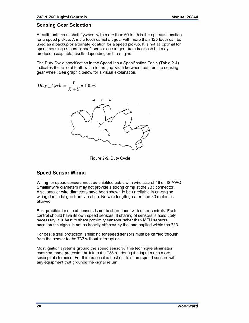
Sensing Gear Selection A multi-tooth crankshaft flywheel with more than 60 teeth is the optimum location for a speed pickup. A multi-tooth camshaft gear with more than 120 teeth can be used as a backup or alternate location for a speed pickup. It is not as optimal for speed sensing as a crankshaft sensor due to gear train backlash but may produce acceptable results depending on the engine. The Duty Cycle specification in the Speed Input Specification Table (Table 2-4) indicates the ratio of tooth width to the gap width between teeth on the sensing gear wheel. See graphic below for a visual explanation.
%100_
YX
YCycleDuty
X
Y
Figure 2-9. Duty Cycle Speed Sensor Wiring Wiring for speed sensors must be shielded cable with wire size of 16 or 18 AWG. Smaller wire diameters may not provide a strong crimp at the 733 connector. Also, smaller wire diameters have been shown to be unreliable in on-engine wiring due to fatigue from vibration. No wire length greater than 30 meters is allowed. Best practice for speed sensors is not to share them with other controls. Each control should have its own speed sensors. If sharing of sensors is absolutely necessary, it is best to share proximity sensors rather than MPU sensors because the signal is not as heavily affected by the load applied within the 733. For best signal protection, shielding for speed sensors must be carried through from the sensor to the 733 without interruption. Most ignition systems ground the speed sensors. This technique eliminates common mode protection built into the 733 rendering the input much more susceptible to noise. For this reason it is best not to share speed sensors with any equipment that grounds the signal return.

Manual 26344 733 & 766 Digital Controls
Woodward 21
There are multiple techniques in use for shield connections of speed sensors. Each technique has varying results depending on the noise present in the area. In general, the most effective shield for a proximity or MPU sensor is carried through to the sensor body via the connector and also connected to the 733 shield pin. Unfortunately terminating both ends of the shield can create ground loops at lower frequencies. The recommended practice is to tie the cable shield to the designated shield pin on the control and leave the opposite end of the shield un-terminated but insulated. Alternatively, a capacitor may be used to connect the sensor body to the shield in addition to connecting the shield to the 733. Connecting the shield at both ends without a capacitor has the potential to create an undesirable ground loop via the engine ground, but may be done if grounds are short enough that no ground currents can flow. To ground the shield at both ends, there must be no low frequency or dc current flow, i.e. the grounds are at the some potential and the shield resistance is greater than or equal to the ground resistance between the two points. (Grounding shields at both ends will improve proximity sensor performance, but if ground loops are present, may degrade other I/O performance, like analog inputs.) If it is not possible to connect the shield to the 733, it should be connected to the sensor instead, but without a capacitor. Shield grounding can be a determinative process, specific applications and RF environments require different shield grounding schemes be followed. See Woodward application note 50532, Interference Control in Electronic Governing Systems, for more complete information. The following diagram shows how to connect a passive, magnetic pickup. Connection to speed input #1 is shown. Speed input #2 is similar. Both inputs share a shield connection. Connections are made to J1.
G3
F3
F2
Passive MPU
+
+
SN
-
Twisted,Shielded cable
733
SS #1
Figure 2-10. MPU Wiring Diagram
MPU1-
J1
MPU1+
MPU2-
MPU2+Shld
Figure 2-11. MPU Connector View

733 & 766 Digital Controls Manual 26344
22 Woodward
Connection SS_1 SS_2Input (+) J1–G3 J1–G1 Input (–) J1–F3 J1–F1 Prox Power (+) J1–D1 J1–D1 Prox Power Common J1–D2 J1–D2 Shield J1–F2 J1–F2
Table 2-5. Speed Sensor Connections
The following diagram shows how to connect an active proximity sensor. Connection to speed input #1 is shown. Speed input #2 is similar. Both inputs share a shield connection. Connections are made to J1. See Table 2-5 for pin out of both speed sensor inputs. The Woodward active proximity sensor is shown. The 733 supplied proximity power should always be used for signal isolation.
733
G3
F3
D1
WoodwardActive Prox
D2
F2
Prox PS+
ProxCommon
A
B
C
+-
s
SN
Twisted,Shielded cable
SS #1
Figure 2-12. Proximity Sensor Wiring Diagram
Px1-
J1
Px1+
Px2-
Px2+Shld
Com
Pwr
Figure 2-13. Proximity Sensor Connector View

Manual 26344 733 & 766 Digital Controls
Woodward 23
Proximity Probe Power Supply A power supply is provided for the proximity probes. This supply must be used to power the probes.
Output Type Voltage source Output Voltage 17 Vdc 20% Output Current 60 mA
Protection Output is protected from short circuit
Table 2-6. Proximity Power Specifications Proximity Probe Power Supply Monitoring Circuit The proximity probe power supply voltage level is monitored for the purpose of application diagnostics. In GAP this value is found in the MCU_STATUS block as “MON_PRX”.
Maximum voltage measured 55 Vdc Measured voltage filter 1 pole at 0.5 ms
Resolution 10 bits (55 mVdc) Accuracy ±1% of full scale typical steady-state
Temperature drift ±1% of full scale (0.55 V) typical ±2.4% of full scale (1.32 V) worst case
Table 2-7. Proximity Probe Power Monitor Specifications
Analog Inputs There are four inputs on the 733 dedicated to analog transducer signals. The Analog Inputs accept a 4–20 mA signal. The Analog Inputs may be used with a two-wire ungrounded (loop powered) transducer or an isolated (self-powered) transducer. It is also possible that some units will be factory configured with 1–5 V Analog Inputs instead of current inputs. This is a factory option that cannot be changed in the field. If interfacing to a non-isolated device that may have the potential of reaching over 20 Vdc with respect to the control’s common, the use of a loop isolator is recommended to break any return current paths, which could produce erroneous readings. Loop power must be provided from an external source. See transducer wiring below for typical wiring. Loop power should always be fused with a 100 mA (or smaller) fuse. This fuse prevents damage to the sensor or to the 733 due to wiring errors or shorts.
Input type 4–20 mA or 1–5 V (factory option) Max. Input current 22 mA ±5%
Common mode rejection 56 dB typical 48 dB worst case
Input common mode range ±20 Vdc Input impedance 200 (±1%) Anti-aliasing filter 2 poles at 0.94 ms and 0.47 ms
Resolution 12 bits Accuracy @ 25 °C ±0.5% of full scale typical
±1.3% of full scale worst case Temperature Drift ±0.4% of full scale (0.08 mA) typical
±1.1% of full scale (0.22 mA) worst case
Table 2-8. Analog Input Specification

733 & 766 Digital Controls Manual 26344
24 Woodward
In GAP, analog input #1 is found in the MCU Module block as “AI_1”. Analog input #2 is “AI_2”. Analog input #3 is “AI_3”. Analog input #4 is “AI_4”. The GAP block “AN_IN” should always be used with these inputs. As these are current inputs, the “IN_TYPE” configuration field should always be set to “1” for 4–20 mA. Application logic should be included to flag errors and take action when input current or any channel is below 4mA or above 20 mA. The input will detect currents outside this valid range so that such diagnostics are possible. Analog Input Wiring Wiring for analog inputs must be shielded cable with wire size of 16 or 18 AWG. Smaller wire diameters may not provide a strong crimp at the 733 connector. Also, smaller wire diameters have been shown to be unreliable in on-engine wiring due to fatigue from vibration. No wire length greater than 30 meters is allowed. Shielding should be unbroken between the sensor and the 733. Shielding should not be grounded anywhere in the system along the cable length. The shield should be connected to the correct Analog Input shield pin on the 733. The shield may be connected to the sensor with an optional capacitor or left unconnected. It is best not to connect both ends of the shield without the use of a capacitor unless the sensor is completely floating with respect to ground. Note that the control’s power supplies are not equipped with input power switches. For this reason, some means of disconnecting input power to each main power supply must be provided for installation and servicing.
External loop powered transducers must be individually protected with a 100 mA (or smaller) fuse on each channel.
733
P2
N3
N2
Transducer+
4-20 mALoop Powered
LoopPwr
AI #1
100mA-
Twisted,Shielded cable
Figure 2-14. Analog Input Wiring Diagram; Loop Powered
733
P2
N3
N2
Transducer+
4-20 mASelf-Powered
AI #1
Isolated Transducer(or power supplygrounded at samepoint as 733 powersupply)
Twisted,Shielded cable
Figure 2-15. Analog Current Input Wiring Diagram; Self-Powered

Manual 26344 733 & 766 Digital Controls
Woodward 25
Most 733 controls will have 4–20 mA inputs. Some may be configured from the factory with 1–5 V inputs instead. In this case, they are wired as shown below.
733
P2
N3
N2
AI #1
Transducer+
1-5 VSelf-Powered
Isolated Transducer(or power supplygrounded at same pointas 733 power supply)
Twisted,Shielded cable
Figure 2-16. Analog Voltage Input Wiring Diagram; Self-Powered
J2
AI-4- AI-4
+
3&4Shld
AI-3+
AI-2-
AI-2+
AI-1-
AI-1+
1&2Shld
AI-3-
Figure 2-17. Analog Input Connector View
Connection AI_1 AI_2 AI_3 AI_4 Input (+) J2–P2 J2–N1 J2–L1 J2–M3 Input (–) J2–N3 J2–M1 J2–M2 J2–L3 Shield J2–N2 J2–N2 J2–L2 J2–L2
Table 2-9. Analog Input Connections
Actuator Output #1 The actuator output may be used with a two-wire ungrounded device or an isolated device. If interfacing to a non-isolated device, the use of a loop isolator is required. This output can be software configured as a 4–20 mA output or a 20–160 mA output. Both configurations also allow operation from 0 mA. Source and return current metering are provided for diagnostic purposes. The current metering is hardware filtered for anti-aliasing. It is also software filtered with a lag filter for the fault outputs, but the analog values provided for the feedback are not software filtered.

733 & 766 Digital Controls Manual 26344
26 Woodward
Actuator Type Proportional
Output Type 4–20 mA or 20–160 mA software selectable
Isolation None
Max current output 22.5 mA ±5% 200 mA ±5%
(4–20 mA range) (20–160 mA range)
Max load resistance 750 (at 20 mA) 80 (at 160 mA)
(4–20 mA range) (20–160 mA range)
Min load resistance 2 8
(4–20 mA range) (20–160 mA range)
Resolution 12 bits Typical Accuracy @ 25°C ±0.8% of full scale (0.16 mA)
±1.1% of full scale (1.76 mA) (4–20 mA range) (20–160 mA range)
Worst Case Accuracy @ 25°C ±2.1% of full scale (0.42 mA) ±3.3% of full scale (5.28 mA)
(4–20 mA range) (20–160 mA range)
Temperature Drift ±0.5% of full scale (0.16 mA) ±1.1% of full scale (1.76 mA)
(4–20 mA range) (20–160 mA range)
Table 2-10. Actuator Output #1 Specification
In GAP, actuator output #1 is found in the MCU Module block as “ACT_1”. The GAP block “ACT_OUT” should always be used with this output. Both the output current and the return current are measured by the 733 circuitry and made available to the GAP application. The current monitoring is provided for diagnostic purposes and should not be used for control. The output current is reported as “RDBK_SRC” in the “ACT_OUT” block. The return current is reported as “RDBK_RET” also in the “ACT_OUT” block. Neither readback currents are software filtered. If either value is to be used in the application for diagnostic purposes, an application filter of 2 rate groups should be added. The block will perform the appropriate diagnostics itself using filtered versions of the readback currents and provides Boolean outputs to indicate error conditions. Actuator Output Wiring Shielding is required for actuator output wiring. Like other analog signals, the shield should be continuous and ungrounded along its length. There is no connection at the 733 for the shield. The shield should be connected at the receiving end for maximum benefit. Like other signals on the 733, maximum wiring length is limited to less than 30 meters. All cabling should be 18 or 16 AWG for proper crimp strength at the 733 connector and for engine vibration durability.

Manual 26344 733 & 766 Digital Controls
Woodward 27
733
H3
G2
+V
Readback
ACT #1
Readback
+
4-20 mA or20-160mA
ProportionalActuator
Twisted,Shielded cable
DGND
Figure 2-18. Actuator #1 Wiring Diagram
J1
Act-1
-
Act-1
+
Figure 2-19. Actuator #1 Connector View
Actuator Output #2 The actuator output may be used with a two-wire ungrounded device or an isolated device. If interfacing to a non-isolated device, the use of a loop isolator is required. This output is a 4–20 mA output. Source and return current metering are provided for diagnostic purposes. The current metering is hardware filtered for anti-aliasing. It is also software filtered with a lag filter for the fault outputs but the analog values provided for the feedback are not software filtered.
Actuator Type Proportional Output Type 4–20 mA
Isolation None Max current output 22.5 mA ±5%
Max load resistance 410 s at 20 mA Min load resistance 2
Resolution 12 bits Accuracy @ 25°C Better than ±0.5% of full scale typical (±0.10 mA)
Better than ±1.3% of full scale worst case (±0.26 mA) Temperature Drift Better than ±0.9% of full scale typical (±0.18 mA)
Better than ±2.5% of full scale worst case (±0.50 mA)
Table 2-11. Actuator Output #2 Specification

733 & 766 Digital Controls Manual 26344
28 Woodward
In GAP, actuator output #2 is found in the MCU Module block as “ACT_2”. The GAP block “ACT_OUT” should always be used with this output. Both the output current and the return current are measured by the 733 circuitry and made available to the GAP application. The current measurement is provided for diagnostic purposes and should not be used for control. The output current is reported as “RDBK_SRC” in the “ACT_OUT” block. The return current is reported as “RDBK_RET” also in the “ACT_OUT” block. Neither is software filtered. If either value is to be used in the application for diagnostic purposes, an application filter of 2 rate groups should be added. The block will perform the appropriate diagnostics itself, using filtered versions of the readback currents and provides Boolean outputs to indicate error conditions. Actuator Output Wiring Shielding is required for actuator output wiring. Like other analog signals, the shield should be continuous and ungrounded along its length. There is no connection at the 733 for the shield. The shield should be connected at the receiving end for maximum benefit. Like other signals on the 733, maximum wiring length is limited to less than 30 meters. All cabling should be 18 or 16 AWG for proper crimp strength at the 733 connector and for engine vibration durability.
733
H1
H2
+V
Readback
ACT #2
Readback
+
4-20mA controlledelectronic actuator
A
Twisted,Shielded cable
DGND
Figure 2-20. Actuator #2 Wiring Diagram
J1
Act-2
-
Act-2
+
Figure 2-21. Actuator #2 Connector View

Manual 26344 733 & 766 Digital Controls
Woodward 29
Analog Outputs There are two analog outputs in addition to the actuator outputs for general use. Each output is a 4–20 mA current source. The Analog Outputs may be used with a two-wire ungrounded device or an isolated device. If interfacing to a non-isolated device, the use of a loop isolator is required. Source current metering is provided for diagnostic purposes. The current metering is hardware filtered for anti-aliasing. It is also software filtered with a lag filter for the fault outputs but the analog value provided for the feedback is not software filtered.
Number of channels 2 Output type 4–20 mA
Isolation None Max current output 22.5 mA ±5%
Max load resistance 420 at 20 mA Min. load resistance 2
Resolution 12 bits Accuracy @ 25°C Better than ±0.5% of full scale typical (±0.10 mA)
Better than ±1.3% of full scale worst case (±0.26 mA) Temperature Drift Better than ±0.9% of full scale typical (±0.18 mA)
Better than ±2.5% of full scale worst case (±0.50 mA)
Table 2-12. Analog Outputs Specification In GAP, analog output #1 is found in the MCU Module block as “AO_1”. Likewise, analog output #2 is found as “AO_2”. The output current is measured by the 733 circuitry and made available to the GAP application through the AN_OUT_420 block. The GAP block “AN_OUT_420” should always be used with this output. The current measurement is provided for diagnostic purposes and should not be used for control. It is not software filtered. If this value is to be used in the application for diagnostic purposes, an application filter of 2 rate groups should be added. The output current is reported as “READBACK” in the AN_OUT_420 block. The block will perform the appropriate diagnostics itself using a filtered version of the readback current and provide a Boolean output to indicate an error condition. Analog Output Wiring Each analog output has identical circuitry. There is no isolation between outputs and no isolation to the digital circuitry of the 733. Wiring for Analog Output #1 is shown below. Only the terminal numbers change for Analog Output #2. Shielding is required for analog output wiring. Like other analog signals, the shield should be continuous and ungrounded along its length. There is no connection at the 733 for the shield. It should be connected at the receiving end for maximum benefit. Like other signals on the 733, maximum wiring length is limited to 30 meters. All cabling should be 18 or 16 AWG for proper crimp strength at the 733 connector and for engine vibration durability.
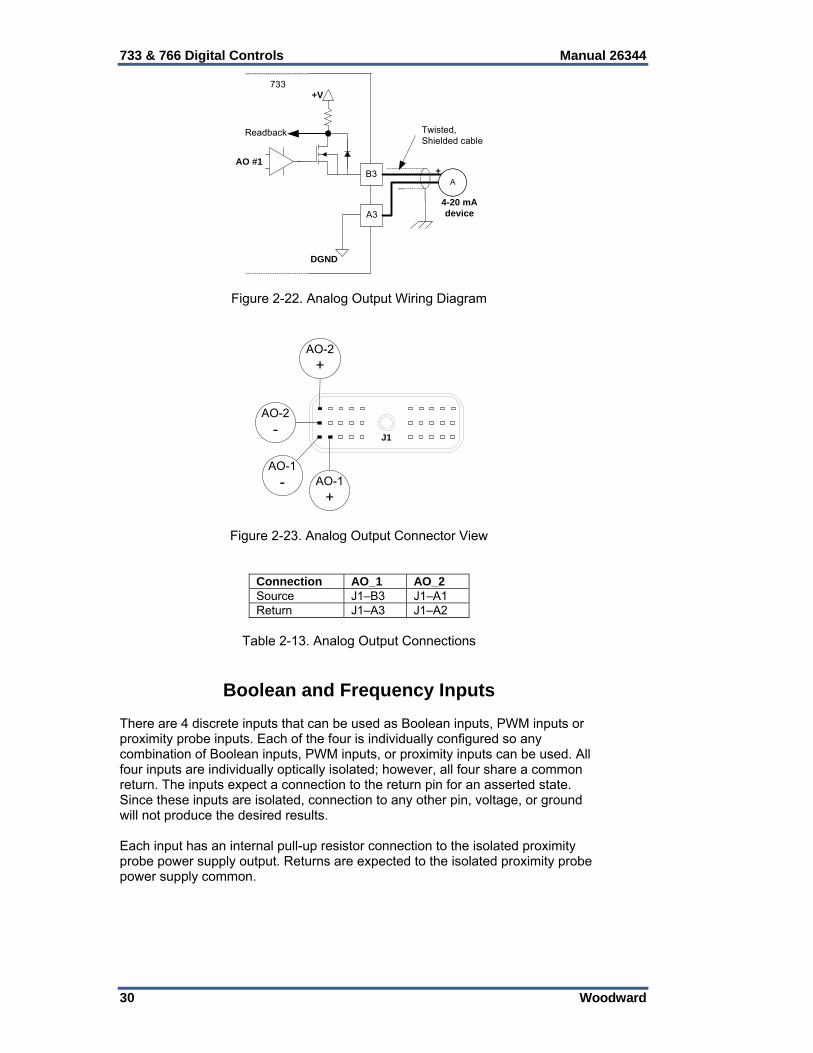
733 & 766 Digital Controls Manual 26344
30 Woodward
733
B3
A3
+
4-20 mAdevice
A
+V
Readback
AO #1
Twisted,Shielded cable
DGND
Figure 2-22. Analog Output Wiring Diagram
AO-1
-
J1
AO-1
+
AO-2
-
AO-2
+
Figure 2-23. Analog Output Connector View
Connection AO_1 AO_2Source J1–B3 J1–A1 Return J1–A3 J1–A2
Table 2-13. Analog Output Connections
Boolean and Frequency Inputs There are 4 discrete inputs that can be used as Boolean inputs, PWM inputs or proximity probe inputs. Each of the four is individually configured so any combination of Boolean inputs, PWM inputs, or proximity inputs can be used. All four inputs are individually optically isolated; however, all four share a common return. The inputs expect a connection to the return pin for an asserted state. Since these inputs are isolated, connection to any other pin, voltage, or ground will not produce the desired results. Each input has an internal pull-up resistor connection to the isolated proximity probe power supply output. Returns are expected to the isolated proximity probe power supply common.

Manual 26344 733 & 766 Digital Controls
Woodward 31
Number of channels 4 Input type Sinking input
Isolation 500 Vdc isolation from the other I/O and circuits Input thresholds > 7 Vdc = “OFF” (internal pull-up to prox supply output)
< 1 Vdc = “ON” Input impedance 15 k
Max input voltage 28 Vdc PWM input frequency 100–1000 Hz
PWM duty cycle 5–95% at 300 Hz 10–90% at 1000 Hz
PWM resolution > 12 bits at 100 Hz to > 10 bits at 450 Hz > 15 bits at 451 Hz to > 14 bits at 1000 Hz
PWM accuracy ±2% for both frequency and duty cycle determination Prox input frequency 10 Hz – 7 kHz
Prox duty cycle 10–90% up to 3 kHz 20–80% from 3 kHz – 7 kHz 20 µs minimum period
Prox resolution > 21 bits at 10 Hz to >11 bits at 7 kHz Prox accuracy ±2% of point
Table 2-14. Discrete and Frequency Inputs Specification
In GAP, discrete input #1 is found in the MCU Module block as “DI_1”. Discrete input #2 is “DI_2”. Discrete input #3 is “DI_3”. Discrete input #4 is “DI_4”. The GAP block “BOOL_IN” should always be used with this input if it is to be used as a Boolean input. The GAP block “AI_PWM” should always be used with this input if it is to be used as a PWM input. Any of the GAP blocks “AI_MPU_ENG”, “TDC”, or “PHASE” may be used with this input if it is to be used as a proximity input. Signal Application To understand the proper application of Boolean, PWM, and Speed signals into the discrete inputs on the 733, it will help to understand how they are used. Since the input is a sinking input, the active condition is actually 0 volts as referenced to the return pin. This is the condition where the input is actively shorted to the return pin thus it is the active state. See the below diagrams for visualization. Note that for speed input usage, the 733 triggers based on the falling edge of the signal.
Pull-up level (~14V)
0V
Signal connected toProx CommonTRUE in GAP
Signal “floating”FALSE in GAP
Figure 2-24. Boolean Usage

733 & 766 Digital Controls Manual 26344
32 Woodward
Pull-up level (~14V)
0V
Signal “floating” 40%of the time
Signal “sinking”60% of the time
Result is that GAP reports 40% duty cycle
Figure 2-25. PWM Usage Proximity Sensor Wiring There are 4 inputs that can be used for connection to proximity sensors. Each input has identical circuitry. Wiring for discrete input #1 is shown below. Only the terminal numbers change for discrete inputs #2, 3, and 4. The input circuitry is internally powered by an isolated source. Proximity probes used with these inputs should be powered from the 733 proximity probe power output. The power source is limited to 60 mA and produces a voltage near 20 Vdc. The power source is current limited for protection from overloading or short circuit connections. Best practice for proximity sensors is not to share them with other controls. Each control should have its own sensors. Shielding is required for proximity sensor wiring. Like other speed signals, the shield should be continuous and ungrounded along its length. For best signal protection, shielding for proximity sensors must be carried through from the sensor to the 733 without interruption. There are multiple techniques for shield connections of proximity sensors. Each technique has varying results depending on the noise present in the area. In general, the recommended practice is to use the 733 shield pin for terminating the shield and leave the sensor end isolated. The shield should NOT be grounded anywhere along the path between the sensor and the 733. Alternatively, a capacitor may be used to connect the sensor body to the shield in addition to connecting the shield to the 733. Connecting the shield at both ends without a capacitor has the potential to create an undesirable ground loop via the engine ground, but may be done if grounds are short enough that no ground currents can flow. To ground the shield at both ends, there must be no low frequency or dc current flow, i.e. the grounds are at the some potential and the shield resistance is greater than or equal to the ground resistance between the two points. (Grounding shields at both ends will improve proximity sensor performance, but if ground loops are present, may degrade other I/O performance, like analog inputs.) If it is not possible to connect the shield to the 733, it should be connected to the sensor instead but without a capacitor. Like other signals on the 733, maximum wiring length is limited to less than 30 meters. All cabling should be 18 or 16 AWG for proper crimp strength at the 733 connector and for engine vibration durability.

Manual 26344 733 & 766 Digital Controls
Woodward 33
E3
D2
D1
WoodwardActive Prox
F2
Prox PS+
A
B
C
+-
s
SN
Twisted,Shielded cable
733
ProxCommon
DI #1
Figure 2-26. Proximity Sensor Wiring Diagram
Com DI-4 DI-1
DI-3 DI-2
J1
+
Figure 2-27. Proximity Sensor Connector View
Connection DI_1 DI_2 DI_3 DI_4 Input J1–E3 J1–E2 J1–E1 J1–D3 Return J1–D2 J1–D2 J1–D2 J1–D2 Prox Power (+) J1–D1 J1–D1 J1–D1 J1–D1 Prox Power Common J1–D2 J1–D2 J1–D2 J1–D2 Shield J1–F2 J1–F2 J1–F2 J1–F2
Table 2-15. Discrete Input Connections
PWM Wiring There are 4 inputs that can be used for connection to PWM devices. Each input has identical circuitry. Wiring for discrete input #1 is shown below. Only the terminal numbers change for discrete inputs #2, 3, and 4. PWM signals may originate from a sensor or from another electronic control. If the signal is provided from a sensor, consider powering the sensor from the 733 proximity power supply output. The power supply output current limit must be evaluated in this case to determine if there is enough power available. The voltage level should also be considered. Where it is not feasible to power the PWM source from the proximity power supply output, it should be an isolated source to avoid creating a connection from the PWM input circuitry back to B- and avoid ground referencing the circuits. The PWM source must be referenced to the proximity power supply common return pin for proper application.

733 & 766 Digital Controls Manual 26344
34 Woodward
Like other signals on the 733, maximum wiring length is limited to less than 30 meters. All cabling should be 18 or 16 AWG for proper crimp strength at the 733 connector and for engine vibration durability. Shielding should be unbroken between the sensor / control device and the 733. Shielding should not be grounded along its length anywhere in the system. The shield should be connected to the MPU shield pin on the 733. The shield may be connected at the source device with a capacitor or left unconnected. It is best not to connect both ends without the use of a capacitor unless the source is completely floating with respect to ground.
ProxCommon
+ProxPwr
E3
D2
733
DI #1
PWM reference(required)
F2
ShieldedTwisted Pair
PWMdevice
Figure 2-28. PWM Input Wiring Diagram Boolean Input Wiring There are 4 inputs that can be used as isolated Boolean inputs. Each input has identical circuitry. Wiring for using all inputs as Boolean is shown below. If some of the inputs are used for PWM or proximity sensors, ignore their connections in the diagram. Like other signals on the 733, maximum wiring length is limited to less than 30 meters. All cabling should be 18 or 16 AWG for proper crimp strength at the 733 connector and for engine vibration durability. Due to the signal isolation of the discrete inputs in this group, it is generally recommended to use one or more of these 4 Boolean inputs for connection to a fast-stop button if such a connection is to be provided. These inputs are preferred over the un-isolated Boolean inputs in the next section purely because of the isolation. In the event of a wire insulation failure to ground, this input will not activate since ground is not the correct return path (this assumes no other wiring errors exist that ground reference the input). These inputs are intended to monitor the fast-stop but they are not certified to perform critical safety functions. Another general recommendation for fast-stop inputs is to use a normally closed contact at the fast-stop button.

Manual 26344 733 & 766 Digital Controls
Woodward 35
ProxCommon
+ProxPwr
E3
D2
733
+ProxPwr
E2
+ProxPwr
E1
+ProxPwr
D3
DI #1
DI #2
DI #3
DI #4
Figure 2-29. Boolean Input Wiring Diagram
Com DI-4 DI-1
DI-3
J1
DI-2
Figure 2-30. Boolean Input Connector View
Boolean Inputs There are 4 strictly Boolean inputs. All four inputs are un-isolated and are designed for use with nearby dry contacts. The inputs expect a connection to the return pin for an asserted state. The return pin is NOT the same return pin used for the 4 configurable discrete inputs described above. Making connections to the wrong return pin will not provide the desired results. It is recommended to use the isolated discrete inputs for critical functions as they tolerate more wiring failure modes than these unisolated Boolean inputs. The Boolean input return should not be connected to any other devices. For best results, connect to the contact of a relay and do not share the contact with other devices.

733 & 766 Digital Controls Manual 26344
36 Woodward
Number of channels 4 Input type Sinking input
Isolation voltage None Input thresholds > 7 Vdc = “OFF” (internal pull-up to proximity supply output)
< 1 Vdc = “ON” Input impedance 15 k
Max input voltage 28 Vdc
Table 2-16. Boolean Inputs Specification In GAP, Boolean input #5 is found in the MCU Module block as “BI_5”. Boolean input #6 is “BI_6”. Boolean input #7 is “BI_7”. Boolean input #8 is “BI_8”. The GAP block “BOOL_IN” should always be used with this input. Boolean Input Wiring Like other signals on the 733, maximum wiring length is limited to less than 30 meters. All cabling should be 18 or 16 AWG for proper crimp strength at the 733 connector and for engine vibration durability.
+V
C3
B2BICommon
733
+V
C2
+V
C1
+V
B1
BI #5
BI #6
BI #7
BI #8
Figure 2-31. Boolean Input Wiring Diagram
Com DI-5
DI-7 DI-6
J1
DI-8
Figure 2-32. Boolean Input Connector View

Manual 26344 733 & 766 Digital Controls
Woodward 37
Boolean and PWM Outputs There are 4 discrete outputs. Each of the outputs can be used as a Boolean output or as a low frequency PWM output. The PWM capability is useful as a controlling signal for some actuators in place of a 4–20 mA signal. Another common use is to drive an analog dashboard meter indicating pressure or temperature. All four outputs are individually optically isolated. However, all four share a common power supply and return circuit. Each output uses a thermally protected MOSFET that will pulse the circuit if the current limit is exceeded. An over-current condition on one output will not affect the other discrete outputs. The output will be pulsed continuously until the current requirement is reduced, allowing the output to operate normally again. No feedback is provided to the software application regarding this condition. Since no feedback is provided for output wiring failures, any output used for a critical function should be duplicated (use 2 outputs) or a fail-safe method should be employed.
Critical outputs should be duplicated (redundant wiring either in series or parallel) or an external means should be used for wiring failure detection. Alternatively, a separate means can be provided for actuating the critical function.
Number of channels 4 Output type Low-side driver with short circuit and over voltage
protection Current drive rating <500 mA used for Boolean purpose
<125 mA used for PWM purpose Discrete Output supply voltage 12-32 Vdc
Isolation voltage 500 Vac, all channels are isolated from the other I/O
Table 2-17. Boolean and PWM Outputs Specification
In GAP, discrete output #1 is found in the MCU Module block as “PWM_DO_1”. Discrete output #2 is “PWM_DO_2”. Discrete output #3 is “PWM_DO_3”. Discrete output #4 is “PWM_DO_4”. The GAP block “BOOL_OUT” should be used with this output when Boolean application is desired. The GAP block “AO_PWM” should be used with the output when PWM application is desired. This is not a current controlled output and no current feedback is provided. An external 12–32 Vdc power source must be provided to source the circuit voltage switched by the 733 discrete outputs. Due to circuit isolation, the external power supply common must be connected to the 733 as shown in the wiring diagrams below. There is no internal isolated supply to power this circuitry. The proximity probe power output should NOT be used for this purpose. It does not have enough capacity and its use would violate the desired input to output isolation needed for noise immunity. If the 733 power input is common to the discrete output power supply then the loads should be isolated. Load isolation can be provided by simply adding relays to the Boolean outputs. If any outputs are used as PWM outputs, an isolated repeater will be necessary unless the load is isolated.

733 & 766 Digital Controls Manual 26344
38 Woodward
PWM Wiring When using discrete outputs as PWM outputs, there is not a pull-up resistor internal to the 733 DO source voltage. Therefore, unless the receiving end has an internal pull-up resistor at the input, one must be provided in the wiring harness or at the terminals of the receiving device (not at the 733 terminals). The PWM output closes a connection between the PWM output pin and DO_RTN. The pull-up resistor should have a low resistance value considering power dissipation and the 150 mA maximum rating on the PWM outputs. Lower resistance values result in faster output slew rates and better immunity to noise. The discrete output slew rate will be the product of the pull-up resistance and the capacitance of the wiring. For example: 30 meters of wiring, at 300 pF per meter and a 1 k pull up resistor will result in a rise time of 9 µs.
skm
pFm 91
30030
The output FETS cannot switch faster than about 10 µs, so typically there is no reason for a pull-up resistor value less than 1 k. Woodward products that may be used with PWM position commands are listed here for reference: The Woodward L-series actuators and FCV (Diesel Common Rail Fuel
Control Valve) have internal pull-up resistors that are activated using a software configuration parameter.
Some Woodward Flo-Tech™ actuators have an internal resistor. Check the
product documentation for your model. All Woodward ProAct™ Digital Plus actuators will require an external pull-up
resistor at the terminals. Like other signals on the 733, maximum wiring length is limited to less than 30 meters. All cabling should be 18 or 16 AWG for proper crimp strength at the 733 connector and for engine vibration durability. Shielding should be unbroken between the 733 and the receiving device. Shielding should not be grounded anywhere in the system along the cables length. The shield should be connected to the receiving device as required in the product manual for that device. Do not make any shield connections for the PWM outputs at the 733.

Manual 26344 733 & 766 Digital Controls
Woodward 39
733
K3
DO #1
DO PwrJ2
K2DOCommon
24V
+
ActuatorPwr
-L-series(FCV)
Figure 2-33. PWM Output Wiring Diagram for L-series, FCV, Flo-Tech
733
K3
DO #1
DO PwrJ2
K2
24V
+
-DOCommon
ActuatorPwr
PWM reference(required)
ProActDig +
+
Figure 2-34. PWM Output Wiring Diagram for ProAct Digital Plus
733
K3
DO #1
DO PwrJ2
K2DOCommon
24V
+
ActuatorPwr
PWM reference
-
PWMcontrolledelectronicactuator
Figure 2-35. PWM Output Wiring Diagram for General Application

733 & 766 Digital Controls Manual 26344
40 Woodward
DO-1
DO-3
ComJ1
DO-4
+ DO-2
Figure 2-36. PWM Output Connector View
Connection DO_1 DO_2 DO_3 DO_4Output J1–K3 J1–J3 J1–K1 J1–J1 Return / DO Power Common
J1–K2 J1–K2 J1–K2 J1–K2
DO Circuit Power (+) J1–J2 J1–J2 J1–J2 J1–J2
Table 2-18. Discrete Output Connections Boolean Output Wiring There are 4 outputs that can be used as Boolean outputs. Each output has identical circuitry. Wiring for all outputs is shown below. If some of the outputs are used for PWM as above, ignore their terminals in the diagram. The discrete outputs are generally designed for connection to a small indicating lamp (LED or incandescent) or a relay coil. The output cannot be synchronized to engine position (crank angle). Like other signals on the 733, maximum wiring length is limited to less than 30 meters. All cabling should be 18 or 16 AWG for proper crimp strength at the 733 connector and for engine vibration durability.

Manual 26344 733 & 766 Digital Controls
Woodward 41
733
K3
J3
K1
DO #1
J1
DO #2
DO #4
DO #3
DO PwrJ2
K2
24V
+
-DOCommon
DO Pwr
Figure 2-37. Boolean Output Wiring Diagram
Figure 2-38. Boolean Output Connector View Note that since the discrete outputs can be used as PWM or Boolean outputs, care should be taken on wiring the Discrete Output power source to avoid loops.
Serial Communication Ports There are two serial ports on the 733. They may both be used simultaneously and may both be configured independently. Performance of any one port will depend on how many ports are in use and the port traffic. Both serial ports share a common isolation. They are isolated from all other circuits, but not from each other. The isolation conforms with SELV Product Safety requirements. Since both ports are common, if they are to be used simultaneously at least one of the ports, at the receiving end, should be isolated from the other so that a ground loop is not created between the two communicating devices via the serial network.

733 & 766 Digital Controls Manual 26344
42 Woodward
These ports are intended as service and monitoring ports; no critical functions should be attributed to them. Data is sent in a free-run mode such that the port is serviced when the microprocessor has extra time. RS-232 Configuration Port RS-232 is an ANSI (American National Standards Institute) standard definition of electrical, functional and mechanical connections for communications between DTE (Data Terminal Equipment) and DCE (Data Communications Equipment) such as connection of a computer to a modem. It has gained wide usage in short-distance applications (15 m/50 ft). In practice, the standard is largely ignored beyond the most rudimentary implementation of electrical signals (±3 to ±15 volts). Woodward’s implementation will support speeds up to 115 K baud. The actual specification allows 19.2K baud at up to 15 m (50 ft).
Transceiver type RS-232C Isolation voltage 500 Vdc SELV rated (common to the RS-485 port)
Baud rates supported 9.6, 19.2, 38.4, 57.6, 115.2 kbps Protocols supported Woodward ServLink, Modbus RTU, Modbus ASCII
Table 2-19. RS-232 Specification
In GAP, the RS-232 port is found in the MCU Module block as “COMM_1”. One of the GAP blocks “SIO_PORT” or “MOD_PORT” should be used with this port. Use “SIO_PORT” for Woodward ServLink (service tool) application. Use “MOD_PORT” for Modbus® * protocols.
*—Modbus is a trademark of Schneider Automation Inc. RS-232 Serial Wiring The connected wiring should meet the requirements of EIA RS-232. This standard states a maximum cable length of 15 m (50 ft) with a total capacitance less than 2500 pF and a data rate not exceeding 56 kbps. The 733 serial port may be configured for data rates up to 115200 bps but may not function properly at this high data rate when a full 15 meters of cable length is used. Since this port is the only serial port that can be used to download application code, we recommend that this port be used exclusively as a Woodward ServLink port. Its intended primary purpose is for configuration using a PC. ServLink is a proprietary Woodward service tool protocol. Configuration can be done using a PC with Woodward’s Watch Window or Merlin service tools. However, it may also be connected to a PC based Human Machine Interface (HMI) for local configuration and monitoring. The port configuration is defined in the GAP program and sets configuration for kbps, parity, data, and stop bits as well as protocol choice. PC’s usually tie the RS-232 signal common to chassis and protective earth; this can allow an unintended current loop to be formed and defeat the protective isolation in the control. Occasionally the current path formed by connecting signal common to chassis can cause damage to the control, or to the un-isolated PC. The typical problems encountered are noise sources, such as surges, or broken power returns damaging the PC. For this reason, the RS-232 signal common is isolated in the 733; however, if RS-485 is used, the signal common may also be grounded at another device on the RS-485 link. If the RS-485 port is being used, it is recommended that an isolator or careful consideration of the system wiring be used prior to connecting a PC to the control.

Manual 26344 733 & 766 Digital Controls
Woodward 43
When not in use, the cable should be disconnected from this port. The RS-232 transceiver has temperature limitations and cannot be used when the 733 is at full operating temperature on a hot engine. Disconnecting the serial cable allows the transceiver to shut down so it is not damaged from the high temperature.
The RS-232 serial cable must be disconnected when not in use or when the 733 is used at full operating temperature. This is also critical for on engine applications. Failure to disconnect the cable can result in damage to the RS-232 transceiver inside the 733.
Interface Cable Characteristics Please refer to INTERFACE CABLE CHARACTERISTICS in the RS-485 Serial Port section elsewhere in this manual. Shielding Shielded RS-232 cable is required between the 733 and any other devices. Unshielded or improperly shielded cables are likely to cause communication problems and unreliable control operation. The shield must always be ac-coupled (connected through a capacitor) at one end and connected directly to earth on the opposite end for proper operation. Improper shield termination to ground can also cause communication problems and unreliable control operation. The 733 has been constructed so that the serial port shield connections are ac coupled to chassis ground (chassis ground must be tied directly to earth). Devices connected to the opposite end of the cable must provide for the direct ground shield connection or a direct ground must be applied at the 733, external to the control’s shield connector pin.
733
W2
X2
T1
T3
SerialCommon
+5VComm
1 596
Connect toT3Connect to
T1Connect toX2
ShieldedNull Modem
Cable
RS 232CTransceiver
RXB
TXB
PC
RXBTXBGND
235
23
5
Figure 2-39. RS-232 Wiring Diagram

733 & 766 Digital Controls Manual 26344
44 Woodward
ShldTX
RX
Gnd
J2
Figure 2-40. RS-232 Connector View RS-485 Serial Port RS-485 is also an ANSI standard definition of electrical connections for communications between devices. Because it uses balanced drivers, it can communicate over long distances (900 m/3000 ft) at high baud rates (115K). This protocol is implemented identically to “RS-422” with the exception that only one twisted pair is required. Both transmitted and received data use the same pair of wires. A common wire is still required since the output ground is isolated. The port supports up to 32 devices as a half duplex, multi-drop communications network. This allows more than one device to be connected to the common bus with a single master requesting data. It requires one twisted pair and common to operate. This port may be used as a Modbus RTU, Modbus ASCII, or ServLink port. All messaging can be independent from the RS-232 port above. This port supports multi-drop communications on all protocols.
Transceiver type RS-485 half duplex Isolation voltage 500 Vdc SELV rated (common to the RS-232 port)
Baud rates supported 9.6, 19.2, 38.4, 57.6, 115.2 kbps Protocols supported Woodward ServLink, Modbus RTU, Modbus ASCII
Table 2-20. RS-485 Specification
In GAP, the RS-485 port is found in the MCU Module block as “COMM_2”. One of the GAP blocks “SIO_PORT” or “MOD_PORT” should be used with this port. Use “SIO_PORT” for Woodward ServLink (service tool) application. Use “MOD_PORT” for Modbus protocols. RS-485 Converters The following table shows a short list of RS-485 converters that have been verified to function correctly with the Woodward In-Pulse™ II control. This is not a complete list, and many other manufacturers and/or models may be perfectly acceptable for use, but at the time of this manual update, they had not been tested.

Manual 26344 733 & 766 Digital Controls
Woodward 45
Description Woodward P/N
Manufacturer Manufacturer P/N
Notes
RS-232 to RS-485
B&B Electronics
485SD9R Port Powered, DB9 Female to DB9 Female
RS-232 to RS-485
1784-1038 B&B Electronics
485SD9TB Port Powered, DB9 Female to Terminal Block
USB to RS-485
B&B Electronics
USOPTL4 Optically Isolated
USB to RS-485
B&B Electronics
USPTL4
Table 2-21. RS-485 Signal Converters
Interface Cable Characteristics When choosing a cable for RS-485, it is necessary to examine the required distance of the cable run and the data rate of the system. Beyond the obvious traits such as number of conductors and wire gauge, cable specifications include a handful of less intuitive terms. Characteristic Impedance (ohms)—A value based on the inherent conductance, resistance, capacitance, and inductance of a cable that represents the impedance of an infinitely long cable. When the cable is cut to any length and terminated with this Characteristic Impedance, measurements of the cable will be identical to values obtained from the infinite length cable. Therefore, termination of the cable with this impedance gives the cable the appearance of being infinite length, allowing no reflections of the transmitted signal. When termination is required in a system, the termination impedance value should match the Characteristic Impedance of the cable. Shunt Capacitance (pF/ft)—The amount of equivalent capacitive load of the cable, typically listed in a per foot or per meter basis (1 pF/ft = 3.28 pF/m). One of the factors limiting total cable length is the capacitive load. Systems with long lengths benefit from using low capacitance cable. Propagation velocity (% of c)—The speed at which an electrical signal travels in the cable. The value given typically must be multiplied by the speed of light (c, 3x10⁸
m/s) to obtain units of meters per second. For example, a cable that lists a propagation velocity of 67% gives a velocity of 0.67 x 3x108
= 2.01x10⁸ m/s. The
higher the percentage, the smaller the signal delay. General recommendations, for serial cable, are listed in Table 2-22.
Impedance 100 ±20% Cable capacitance 49.2 pF/m (15.0 pF/ft) at 1 kHz Propagation Velocity 67.0% Data Pairs 0.8 mm² (18 AWG) tinned copper Signal attenuation 6.0 dB maximum
Table 2-22. Serial Cable Requirements

733 & 766 Digital Controls Manual 26344
46 Woodward
Network Construction While there are a number of different ways to physically connect devices on a network, for best performance, Woodward recommends that multi-drop networks be constructed using a “daisy chain” configuration or a “backbone with stubs”. In a daisy chain configuration, wires are run from device one to device two to device three, etc. In a backbone with stubs configuration, a main trunk line is run between the two devices that are physically farthest apart and have the physically longest cable. Stub lines are run from the intermediate devices to the trunk line. Stubs should be kept as short as possible. See Figure 2-44 for a graphical representation. The RS-485 specification states that a common wire is needed if there is no other ground path between units. The preferred method for isolated ports is to include a separate common wire in the cable that connects the circuit commons together. Non-isolated nodes may not have a signal common available. If a signal common is not available, use the alternate wiring scheme of connecting all circuit commons of isolated nodes to the shield, and connecting the shield to earth ground at a non-isolated node. Termination To achieve best performance with RS-485 serial communication networks, it is necessary to terminate the network to prevent interference caused by signal reflections. (RS-232 networks are short enough that termination is not required.) Woodward has provided, built-in, network termination resistors for the RS-485 serial port to ease network setup and configuration. The resistor network used is a special design intended to provide maximum noise immunity. The same design should be used at the opposite end of the network. See the circuit diagram (Figure 2-41). This termination network is necessary due to limitations of the Modbus protocol. To activate the termination resistors, external jumpers must be placed at the connector. See Figures 2-41 and 2-42 for jumper locations. As a rule, no matter how many units are on a network, there should never be more than two network terminations installed. Termination resistors must be installed only on the two units that are at the physical ends of the network. Terminating more than two units can overload the network and put it into a cyclic thermal shutdown mode. Shielding Shielded RS-485 cable is required between the 733 and any other devices. Unshielded or improperly shielded cables are likely to cause communication problems and unreliable control operation. The shield must always be ac-coupled (connected through a capacitor) at one end and connected directly to earth on the opposite end for proper operation. Improper shield termination to ground can also cause communication problems and unreliable control operation.

Manual 26344 733 & 766 Digital Controls
Woodward 47
The 733 has been constructed so that the serial port Shield connections are ac coupled to chassis ground (chassis ground must be tied directly to earth). Devices connected to the opposite end of the cable must provide for the direct ground shield connection or a direct ground must be applied at the 733, external to the control’s termination connector pin.
733
X1
W3
W1
Y2
W2
X3
RS 485Transceiver
-
+
SerialCommon
RS 485Device
-+
ShieldedTwisted
Pair
+5VComm
243
140
243
+5VComm
C
Figure 2-41. RS-485 Wiring Diagram
Shld+
-
Gnd
J2
Jumper to applyterminationnetwork
Jumper to applyterminationnetwork
Keepjumpers
short
Figure 2-42. RS-485 Connector View
CAN Communication Ports There are 3 CAN ports for distributed I/O, distributed control, and Human Machine Interface (HMI) purposes. Each port operates independently. Communications is controlled via GAP rate groups and is deterministic. Care should be given to the choice of devices used on each network. HMI devices should generally not be put on distributed control networks with real time control requirements.

733 & 766 Digital Controls Manual 26344
48 Woodward
Port 1 is electrically isolated from all other circuits in the 733. It may be used for on-engine or off-engine communications. Isolation used on this port is SELV rated with respect to product safety requirements. Ports 2 and 3 are partially isolated as a single group; both CAN ports share a common isolation. They are isolated from most other circuits but not from each other and not from the power input. The isolation does NOT conform to product safety SELV requirements and is considered to be hazardous live. Neither port should be used for communication off the engine. They are designed for on-engine distributed control. Each of the 3 ports support SAE J1939 and CiA CANopen network protocols. Either protocol may be used on any port.
Transceiver type CAN 2.0B Isolation voltage 500 Vdc SELV rated (port #1)
500 Vdc hazardous live rated (ports #2 and #3) Baud rates supported 125, 250, 500, and 1000 kbps
Protocols supported CANopen, SAE J1939
Table 2-23. CAN Specification In GAP, the CAN ports are found in the MCU Module block as “CAN1_PORT”, “CAN2_PORT”, and “CAN3_PORT” respectively. The GAP block “CAN_PORT” must be used with these ports. Recommended Bulk Cable Use shielded CAN compatible cabling for all CAN networks. “DeviceNet” cable is a good example of CAN cable for use with isolated CAN ports, but caution should be used as most DeviceNet cables are not rated for on-engine temperatures. It is typically suitable for wiring between switchgear cabinets and an engine junction box where the temperatures are lower. Also, both the “thick” and “thin” DeviceNet cables have wire insulation and wire size that is not compatible with the 733 connectors. When using DeviceNet cables outside a vibration damped enclosure, use the “Thick” or “Trunk” cable. The “Thin” or “Drop” cables have very small wire sizes that fatigue easily. Below are two DeviceNet CAN cables that are compatible with isolated CAN use off engine. Part Number Description Belden 7896A PVC, 18 AWG shielded data pair, 16 AWG shielded power pair.
NEC/UL TC-ER, CSA I/II, A/B. Lapp Cable 2710-250
Halogen free, 18 AWG shielded data pair, 15 AWG shielded power pair. UL and CSA approved.
“J1939” cable is a good example of CAN cable for use with un-isolated CAN ports and for on-engine use. This cable does not include the extra wire used to carry the common reference. It is suitable for use with CAN2 and CAN3 on the 733. It can also be used with CAN1 (the isolated port) if an extra wire is used for CAN common. Raychem makes a compatible cable as do many other manufacturers. Part Number Description Raychem 2019D0301
Cheminax, J1939-11, 0.75 mm2, 120 characteristic impedance, 10.5 pF/ft mutual capacitance, 74% velocity of propagation

Manual 26344 733 & 766 Digital Controls
Woodward 49
The basic cable requirements are listed below. When selecting other cables, be sure they meet these requirements. Data pair impedance 120 ±10% at 1 MHz
Cable capacitance 12 pF/ft at 1kHz (nominal) Capacitive unbalance
1200 pF/1000 ft at 1 kHz (nominal)
Propagation delay 1.36 ns/ft (maximum) DC Resistance 6.9 / 1000 ft @ 20C (maximum)
Data Pair 0.75 mm2 – 1.0 mm² corresponds to 20 – 18 AWG, individually tinned, 3 twists/foot
Power Pair (DeviceNet only)
0.75 mm2 – 1.5 mm² corresponds to 20 – 16 AWG, individually tinned, 3 twists/foot
Drain / Shield Wire 0.75 mm2 – 1.0 mm² Tinned Copper drain wire inside a braid or foil shield
Signal attenuation 0.13 dB/100 ft @ 125 kHz (maximum) 0.25 dB/100 ft @ 500 kHz (maximum) 0.40 dB/100 ft @ 1000 kHz (maximum)
Table 2-24. Cable Specification
Figure 2-43 illustrates what the DeviceNet cables will look like including shielding. There is a foil tape around each conductor pair as well as a braided shield around the entire group of conductors. J1939 cables will not include the DC power pair and related extra shielding.
Figure 2-43. CAN cable cross-section Network Construction There are a number of different ways to physically connect devices on a CAN network. Woodward recommends that multi-drop networks be constructed using either a “daisy chain” configuration (also called zero length drop line) or a “backbone” with very short drop lines for best performance. In a daisy chain configuration, wires are run from one device to the next device without drop lines.

733 & 766 Digital Controls Manual 26344
50 Woodward
In a backbone with stubs configuration, a main trunk line is run between the two devices that are physically farthest apart and have the physically longest cable. Stub lines are run from the intermediate devices to the trunk line. Stubs should be kept as short as possible and may never exceed 6 m (20 ft). As shown in Figure 2-44, it is acceptable to mix both methods on the same network.
Figure 2-44. CAN System Wiring Example A daisy chain (zero drop length) connection is not feasible at the 733 connection due to the sealed connector design. The next best alternative is to use a very short drop line from the trunk into the 733. Special ‘T’ connectors (Tap in the diagram above) are available from multiple manufacturers to ease the wiring harness manufacture. Also available from the same manufacturers, are termination resistors that plug directly into the ‘T’ connectors for the network ends. Due to the port isolation on port 1, a common wire is needed between all units on the network. The preferred method for isolated ports is to include a separate wire within the CAN cable. This keeps the communications and ground reference at the same potential at all times. The DeviceNet cables listed in this manual have the common wire feature. Non-isolated nodes may not have a signal common available for connection. If a signal common is not available, use the alternate wiring scheme of connecting the CAN ground wire from the isolated nodes to the B- terminal at a non-isolated node. B- is typically the signal reference for CAN if isolation is not provided. The CAN common wire should not be grounded. The only exception to this rule is if one of the devices on the link is not isolated, then connecting CAN common to B- on that device may create a connection to the B- power supply ground, assuming the power supply has a connection to ground. Otherwise, no other connections to ground or physical earth should be provided.

Manual 26344 733 & 766 Digital Controls
Woodward 51
Termination It is necessary to terminate the network to prevent interference caused by signal reflections. Depending on network length, many CAN networks will not operate without proper termination. In order to allow the possibility of removing and inserting a unit onto a running network, the CAN termination network is not included inside the 733 control. An external CAN termination network must be provided. As a rule, no matter how many units are on a network, there should never be more than two network terminations installed. Termination resistors must be installed only for the two units that are at the physical ends of the network. Terminating more than two units can overload the network and stop all communications. Termination is a simple 121 Ohm, ¼ watt, 1% metal film resistor placed between CAN high and CAN low terminals at the two end units, a differential termination. Do not connect the termination resistor to anything besides the CAN high and CAN low wires. Shielding Shielded CAN cable is required between the 733 and any other devices. Unshielded or improperly shielded cables are likely to cause communication problems and unreliable control operation. Improper shield termination to ground can also cause communication problems and unreliable control operation. The standard for CAN networks is that each device will have an ac-coupled shield connection (ac-coupled: connected through a capacitor). Additionally a single direct network shield ground location may be provided in some situations. Typically the direct shield grounding location does not have to be at a unit connector, it can be any convenient place in the system. The 733 has been constructed so that the CAN port #1 shield connection is ac coupled to chassis ground, chassis ground must be tied directly to earth ground. The 733 has been constructed so that the CAN ports #2 & #3 shield connection is directly coupled to chassis ground, chassis ground must be tied directly to earth ground. CAN port #1 may also have the CAN cable’s shield tied directly to ground, but care must be taken in how this is accomplished, see Figure 2-45 below. It is expected that each network have one direct connection to chassis ground. The chassis grounding point should be choose for its proximity to ground noise generators and node connections. CAN Port 1 Wiring CAN Port #1 may be used for off-engine wiring to control rooms. It is electrically isolated from all other circuits in the 733. Isolation used on this port is SELV rated for product safety requirements.

733 & 766 Digital Controls Manual 26344
52 Woodward
Wiring length restrictions depend on the baud rate used. Table 2-25 is appropriate for CANopen, at the 4 supported baud rates. The “Trunk” is the length between the two units that are at the physical ends of the network. The “Cumulative Drop” is the added length of all drop wires from the trunk to the devices. This only applies to “backbone” type networks since Daisy chain networks do not have drops. The “Maximum Drop” is the maximum allowed for any 1 drop. Any network configured for 1000 kbps should use the daisy chain topology to reduce the possibility of reflections. SAE J1939 protocol is restricted to 250 kbps and the SAE J1939 standard limits wiring distances to 40 meters, when un-isolated controls are connected on the link. The limits below are the maximum allowed by the CAN standard. To maintain a high level of reliability in practice, shorter lengths are highly recommended.
Baud Rate Trunk Length Cumulative Drop Maximum Drop125 kbps 500 m (1640 ft) 156 m (512 ft) 6 m (20 ft) 250 kbps 250 m (820 ft) 78 m (256 ft) 6 m (20 ft) 500 kbps 100 m (328 ft) 39 m (128 ft) 6 m (20 ft) 1000 kbps 25 m (82 ft) Not recommended Not recommended
Table 2-25. CAN-1 Wiring Limitations
733
S2
S1
S3
+5VCAN-1
T2CAN-1 Com
CANTransceiver
H
L
ShieldedCAN Cable withCommon wire
(Termination resistorsnot shown)
CANDevice
H
L
Com
Figure 2-45. CAN-1 Wiring Diagram
CAN1L
J2
CAN1H ComShld
Figure 2-46. CAN-1 Connector View

Manual 26344 733 & 766 Digital Controls
Woodward 53
CAN Ports 2 and 3 Wiring CAN Ports 2 and 3 are partially isolated as a common group. They are isolated from most other circuits but not from each other and not from the power input. The isolation does not conform to SELV product safety requirements and is considered to be hazardous live. Neither port should be used for communication off the engine. They are designed for on-engine distributed control. As a result of the isolation style for these ports, they must be limited to 30 meters or less wiring length between the two devices at the physical ends of the network. This limit is further reduced to 25 meters if 1000 kbps baud rate is used. Both CAN port #2 and CAN port #3 have identical circuit designs. Only the pin out for CAN port #2 is shown. The pin out for CAN port #3 is similar except with different terminal numbers for CAN high and low signals. Both ports share the same shield pin.
733
P3
R3
+5VCAN-2/3
Y1CAN-2/3 Com
CANTransceiver
H
L
ShieldedCAN Cable
(Termination resistorsnot shown)
CANDevice
H
L
Com
R2
B- B-
Figure 2-47. CAN-2 and CAN-3 Wiring Diagram
CAN2H
J2
CAN3L
Com
CAN2L
CAN3H
Shld
Figure 2-48. CAN-2 and CAN-3 Connector View
Connection CAN_2 CAN_3 CAN High J2–P3 J2–P1 CAN Low J2–R3 J2–R1 CAN Common J2–Y1 J2–Y1 Shield J2–R2 J2–R2
Table 2-26. Engine CAN Connections

733 & 766 Digital Controls Manual 26344
54 Woodward
Chapter 3. Serial Communications
Modbus Communication The 733 can communicate with plant distributed control systems (DCS) and/or CRT-based operator control panels through Modbus communication ports. These ports support communications using ASCII or RTU MODBUS transmission protocols. Modbus uses a master/slave protocol. This protocol determines how a communication network’s master and slave devices establish and break contact, how a sender is identified, how messages are exchanged, and how errors are detected. The 733 supports two Modbus transmission modes. The mode defines the individual units of information within a message and the numbering system used to transmit the data. Only one mode per Modbus network is allowed. The supported modes are ASCII (American Standard Code for Information Interchange), and RTU (Remote Terminal Unit). These modes are defined in Table 3-1.
CHARACTERISTIC ASCII RTUCoding System hexadecimal (uses 8-bit binary ASCII printable binary characters: 0-9, A-F) Start Bits 1 1 Data Bits per Char 7 8 Parity even, odd, or none even, odd, or none Stop Bits 1, 1.5, or 2 1, 1.5, or 2 Baud Rate 110, 300, 600, 1200, 110,300, 600, 1200, 1800,2400, 4800, 9600, 1800, 2400, 4800, 9600, 19200, 38400, or 57600 19200, 38400, or 57600 Error Checking LRC (Longitudinal CRC (Cyclical Redundancy Check) Redundancy Check)
Table 3-1. ASCII vs. RTU Modbus
In the RTU mode, data is sent in 8-bit binary characters and transmitted in a continuous stream. In the ASCII mode, each binary character is divided into two 4-bit parts (high order and low order), changed to be represented by a hexadecimal equivalent, then transmitted, with breaks of up to 1 second possible. Because of these differences, data transmission with the ASCII mode is typically slower (see Figure 3-1).
Figure 3-1. ASCII/RTU Representation of 3

Manual 26344 733 & 766 Digital Controls
Woodward 55
The Modbus protocol allows one master and up to 247 slaves on a common network. Each slave is assigned a fixed, unique device address in the range of 1 to 247. With the Modbus protocol, only the network master can initiate a transaction. A transaction consists of a request from the master to a slave unit and the slave’s response. The 733 can directly communicate with a DCS or other Modbus supporting device on a single communications link, or through a multi-dropped network. If multi-dropping is used, up to 246 devices (733 or other devices) can be connected to one Master device on a single network. Each message to or from a master has a defined structure called the message “frame”. A frame consists of the slave device address, a code defining the requested data, and error checking information (see Figure 3-2).
BEGINNING OF FRAME
SLAVE ADDRESS
FUNCTION CODE
DATA ERROR CHECK CODE
END OF FRAME
ASCII
: 2 CHARS 8 BITS
2 CHARS 8 BITS
4 BITS DATA PER CHAR
2 CHARS 8 BITS
CR LF
RTU
3-CHAR DEAD TIME
1 CHAR 8 BITS
1 CHAR 8 BITS
8 BITS DATA PER CHAR
2 CHAR 16 BITS
3 CHAR DEAD TIME
Figure 3-2. Modbus Frame Definition
The Modbus function code tells the addressed slaves what function to perform. Table 3-2 lists the function codes supported by this control. Modbus Function Codes
CODE DEFINITION REFERENCE ADDRESS
01 Read Digital Outputs 0XXXX (Raise/Lower and Enable/Disable Commands)
02 Read Digital Inputs 1XXXX (Status Indications / Alarms and Trips)
03 Read Analog Outputs 4XXXX
04 Read Analog Inputs 3XXXX (Speed, Setpt, etc)
05 Write Single Discrete Output 0XXXX (Raise/Lower and Enable/Disable Commands)
06 Write Single Register 4XXXX (Enter Setpt Directly)
08 Loopback Diagnostic Test N/A (supports subfunction 0 only)
15 Write Digital Outputs 0XXXX
16 Write Analog Outputs 4XXXX
Table 3-2. Modbus Function Codes

733 & 766 Digital Controls Manual 26344
56 Woodward
When a Modbus message is received, it is checked for any errors or invalid data. If there is invalid data in the message, an error code is sent back to the master and the master issues an alarm message. The error codes are defined in Table 3-3. Modbus Slave Exception Error Codes
CODE ERROR MESSAGE TO MASTER DESCRIPTION
0 No Error 0 No Error.
1 Bad Modbus function 1 The specified function is not supported for this control.
2 Bad Modbus data address
2 The Modbus value address is not valid for this control.
3 Bad Modbus data value
3 Too many values requested or the on/off indicator in function code 5 is invalid.
9 Bad Modbus checksum
None Message checksum did not match.
10 Bad Modbus message
None Message could not be decoded.
n/a Lost Modbus link None No messages received for the configured time-out period
Table 3-3. Modbus Error Codes
Port Adjustments Before the 733 will communicate with another device, the communication parameters must be verified. These values are set in the GAP™ program, and the GAP programmer may also make these values tunable if desired.
PARAMETER ADJUSTMENT RANGE
Baud Rate 110 TO 57600
Parity NONE, ODD, or EVEN Stop Bits 1 TO 2
Driver RS-232, RS-422, or RS-485
Table 3-4. Modbus Communication Port Adjustments

Manual 26344 733 & 766 Digital Controls
Woodward 57
Chapter 4. Programming and Service Tools
Introduction Two program download and service tools are available for the 733 control. The Woodward Toolkit is the primary service software. The alternate service software is the Woodward Watch Window system. Both software tools run on a PC that is connected to the control with a RS-232 serial cable. When Watch Window is used, also running on the same PC is the Woodward ServLink server software that allows Watch Window to access selected application variables that were generated in the GAP™ application program. The details of the specific GAP application programming are beyond the scope of this manual, but Woodward publication number 80018 is available to assist the application engineer in this process. Two versions of Toolkit are available for use with the 733: 1. Toolkit Professional is a licensed software tool that enables the application
engineer to modify or create new screens for service configuration. At the point of creating new screens, Toolkit Professional is used to: Configure the control software to the specific site or application needs Monitor and tune system variables that were selected in the GAP
application program Trend variables Upload and download all tunable and configuration variables from the
control 2. The standard Toolkit is a software tool that does not have the capability to
modify screens. Otherwise, it provides the same functionality as Toolkit Professional.
Two versions of Watch Window are available for use with the 733: 1. Watch Window Professional is a licensed software tool that enables the
GAP-generated application program to be downloaded into the control. Watch Window Professional is used from the point a GAP-generated program is downloaded to: Configure the control software to the specific site or application needs Monitor and tune system variables that were selected in the GAP
application program Upload and download all tunable and configuration variables from the
control 2. Watch Window Standard is a software tool that does not have the capability
to download application software. Otherwise, it provides the same functionality as Watch Window Professional
This chapter covers the following procedures: Connecting the 733 to a PC Loading the Watch Window System or Toolkit software on the PC Applying power to the control Opening communications with the control Downloading the GAP-generated application software to the 733 Using software to view variables and to tune the control Uploading and downloading tunable and configuration variables from/to the
733

733 & 766 Digital Controls Manual 26344
58 Woodward
Connecting the 733 to a PC Connection of a generic PC to the 733 is required in order to load application software and view/tune within that software application. Figure 4-1 shows the connection details. (Also see the Serial Communication Ports, RS-232 Serial Wiring section for cautions and warnings.)
159 6
J2
ShieldedNull Modem
Cable
Figure 4-1. Connecting the 733 to a PC
Loading Woodward Software Tools on the PC Woodward’s Toolkit, Watch Window Standard, and Watch Window Professional tools may be downloaded from the Woodward website (www.woodward.com/software/). Alternatively, a Toolkit CD Install Kit or Watch Window CD Install Kit may be purchased from your Woodward distributor. Once downloaded, the kit’s Setup.exe program will guide the user through the installation of Toolkit or Watch Window and ServLink software on the PC hard drive.
Applying Power to the 733 At power-up, the 733 runs through its boot-up routine and performs a set of initial diagnostics to verify CPU, memory, and bus health. This boot-up routine takes up to 5 seconds to execute. When boot-up is complete, the application program (if loaded) will begin running, the control’s outputs will be enabled, and system control will begin.
Toolkit Software Instructions Establishing Communications with the 733 Step 1 – Opening a Project File Before communications can begin between the Toolkit software and the 733, a Project File should be opened. To open a project file, select Open Project in the File menu. Toolkit project files have a .WPRJ file extension. The file browser will open in your default location for projects as configured in Toolkit Defaults. You do not need to be connected to a control to open a project file.

Manual 26344 733 & 766 Digital Controls
Woodward 59
Step 2 – Connecting to the 733 1. Make sure that all other programs or devices that may access your
computer’s communication port are shut down. 2. Select Connect from the Communication menu in Toolkit. The user must
select the COM port (unless the correct port is configured as the default in the Options… dialog of the Tools menu). Toolkit automatically detects the baud rate of the control.
3. Once connected to the control, the project association (SID file version) will be compared to the application in the control. The default project association file is automatically loaded with the Project File in step 1. If the default SID file does not match the application in the control, a warning similar to the following will be displayed.
For proper operation, open the correct Project File from the File menu. 4. If connection is successful, the login window may be opened. If no
password requirements are set in the control, the login window will not appear.
5. If the login prompt is canceled or the login level used does not have
sufficient security level to view a parameter, a lock symbol will appear next to the secure parameters with the words “Not Authorized” in the field.

733 & 766 Digital Controls Manual 26344
60 Woodward
Downloading the GAP Application Code The 733 may be shipped from the factory with a default GAP program. If no application is loaded or a new application needs to be loaded, the application can be downloaded by selecting the option Load Application from the File menu. This will start the Load Application Wizard. Toolkit will prompt the user to make a connection to the control if one does not already exist. If any changes to the settings in the control have been made that should be saved, they should be saved before performing the application download. All settings will be modified to what is stored in the application file with the download. After the download is complete the user can then reload the proper settings.
The engine must be shut down prior to starting download of a new application.
Download the Application File 1. Select the option Load Application from the File menu.

Manual 26344 733 & 766 Digital Controls
Woodward 61
2. A warning screen will ask that the user make sure the prime mover is shut down before downloading. When the warning screen has been addressed by clicking Next >, the application file (SCP) to load into the 733 must be selected.
3. Once the file is selected, click Next > to begin the download. The 733 will
automatically reboot and start a boot loader to accept the new program.
After the new connection is established (automatically) the new application
download will begin. A progress meter indicates the download status. The download should not be interrupted or canceled. If it is, there will be no
valid application in the 733. Another attempt to download will be possible, but the previous application version will not be available for use.

733 & 766 Digital Controls Manual 26344
62 Woodward
4. When downloading is complete, the control will reboot automatically. When reboot is completed, the control will begin execution of the new application program.
5. After downloading an application, the user may desire to reload the application settings (if applicable). See the online help in Toolkit for instructions on using settings files.
Be sure the engine is shut down before downloading. Damage to the engine or other serious problems can result if the engine is running during the download procedure.
Using Toolkit Here are brief instructions for using the Toolkit to view and tune the variables for your 733. These instructions are meant to be introductory. Full on-line help is available in Toolkit. There are three basic types of control parameters within Toolkit. These are: Non-adjustable parameters Adjustable parameters Adaptive parameters Non-adjustable Parameter A non-adjustable parameter is shown in a white, frameless box or in a graphic format. See below for an example of non-adjustable parameters.

Manual 26344 733 & 766 Digital Controls
Woodward 63
Adjustable Parameter Adjustable control parameters come in three types: calibration, tunable, and configurable. These three types of adjustable parameters appear the same. Adjustable control parameters are displayed in a sunken box, as shown below, or sometimes as a check box or enumerated list in a drop down.
To change an adjustable parameter, either click the box for a Boolean, select from a drop down list, or click within the cell for an analog or integer. Every adjustable parameter has limits associated with it. The limit can be found when the cursor is within an adjustable parameter box by looking at the bottom of the screen as shown below. This sample parameter has a minimum limit of 100 and a maximum limit of 800.
Also if the user types a value outside the range allowed, the following prompt will be displayed.
When a value is modified the change immediately takes effect in the control. To save the changes permanently, select Save Values from the Device menu. A configurable parameter is a special type of parameter that is changed but not used until the next reboot. When the 733 is rebooted, the new value will take effect. Adaptive Parameter The third type of control parameter is an adaptive point. This is a special tunable that can be modified by the control software and the user simultaneously.
Watch Window Software Instructions Opening Communications with the 733 Initial 733 Communications Before communications can begin between the Watch Window software and the 733, a Network Definition file must be created. Once this file is created and saved, it never has to be recreated unless a new GAP application program is installed.

733 & 766 Digital Controls Manual 26344
64 Woodward
Create the Network Definition File 1. Make sure that all other programs that may access your computer’s
communication port are shut down and you know which comm port the control is located on.
2. Start the ServLink software by selecting Start> Programs> Woodward> Watch Window Professional (or Watch Window Standard)> ServLink Server on the PC. Then select File> New on the ServLink dialog window. In the dialog window (shown below) select the proper COM port for your computer, select POINT TO POINT communications mode, and set the baud rate to 38400. This is the factory default baud rate. If the control has been re-programmed after leaving the factory, the user may need to contact the entity that supplied the new program to determine the correct baud rate.
If a previous download activity was interrupted before completion of the download, the control will have no installed program. In this instance, after the control is reset and the boot-up period has elapsed, the control will continuously scan COM1 port at 57600 and 115200 baud looking for a connection to ServLink. The user may have to hit <Retry> a few times until the control and ServLink baud rates are matched and communications are established.
3. Select OK. If everything is working correctly there will be an animated
graphic of a string of “1”s and “0’s flying from the control to the PC on the screen. Once this transfer is completed, a Network Definition file whose default name is NET1.NET will have been generated. This file should be saved by using the ‘File> Save As’ feature on the PC. Link this name to the control part number since it will only work with that application. For example, if the control part number is 8273-040, one can save the Network Definition file as 8273040.NET. See example below. Do not disconnect the server.

Manual 26344 733 & 766 Digital Controls
Woodward 65
4. In the ServLink window there will be another dialog window entitled “your
filename.NET”. Unless the user has given the control a serial number (or name) with the SLSN.EXE program, this name will display as “<unidentified>”. The user should note this name. See example below.

733 & 766 Digital Controls Manual 26344
66 Woodward
Downloading the GAP Application Code The 733 may be shipped from the factory with a default GAP program. In order to download a new GAP-generated application program it is necessary to use the Watch Window Professional service tool. The following steps are required for this program downloading process. Download the Application File 1. Start the Watch Window program by selecting Start> Programs>
Woodward> Watch Window Professional> Watch Window Professional on the PC. It will ask for a .NET file that corresponds with the application in the control. Open the previously saved file. Under the title bar in the Explorer section of the screen, a tab with the Network Definition filename and the Control ID will be displayed. Right click on this tab to display a pop-up menu and select LOAD APPLICATION. See example screen below.

Manual 26344 733 & 766 Digital Controls
Woodward 67
2. Once the Load Application selection has been made, the Inspector window will close and a new window will appear. In this new window the user enters the name of the file that is to be downloaded into the control. Once the filename is correct, click on the Open button. See example below
3. A warning screen will ask that the user make sure the prime mover is shut
down before downloading. When the warning screens have been addressed, the downloading will commence automatically. This may take several minutes depending on the size of the application. When downloading is complete, the control will reboot automatically. When reboot is completed control will begin execution of the new application program. All associated settings, actuators etc. must be ready to execute the new software.
4. At the end of the download process, an Information window will appear in Watch Window (see below) to alert the user to the fact that a new Network Definition file must be created that matches the new program that has been downloaded. The same procedure that was used initially to create a Network Definition file can be used again.
Be sure the engine is shut down before downloading. Damage to the engine or other serious problems can result if the engine is running during the download procedure.

733 & 766 Digital Controls Manual 26344
68 Woodward
Using Watch Window Here are brief instructions for using the Watch Window in conjunction with ServLink to view and tune the variables for your 733. These instructions are meant to be introductory. Full on-line help is available in each application. It is assumed that you already have ServLink and Watch Window installed. The default installation location can be found by clicking the START icon (Microsoft Windows 95 or later) on the main menu bar and then clicking the PROGRAMS menu item. Look for an icon called WOODWARD WATCH WINDOW. 1. Make sure that all other programs that may access your computer
communications port are shut down and you know the communication port connected to the control.
2. Start the ServLink server and open a new file. Select the proper COM port for your PC, verify that POINT TO POINT communications mode is selected, and verify that the baud rate matches the baud rate of the 733 control. See the on-line help file if you have been changing the port settings of your control.
3. Select OK. If everything is working right, you should see an animated picture of a string of “1”s and “0”s flying from the control to the PC on your screen. You now have a network definition file whose default name is NET1. You should save this file as “your filename.net” (use FILE/SAVE AS). Link this name to your control part number since it will work only with that application. For instance, if the upper level control number is 8273-040, you could save the file as 8273040.NET. Do not disconnect the server.
4. In the ServLink window you will now have another dialog window titled “your filename.net”. In this window you will see a ballhead icon and a control identifier name. Unless you have given the control a serial number (or name) with the SLSN.EXE program, this name will display as “<unidentified>”.
5. Start the Watch Window application. When Watch executes, you will have a screen displaying three windows entitled Watch Window, Explorer, and Inspector.
6. The Explorer window will have two groups displayed, SERVICE and CONFIGURE. Double clicking on either of these will expand them to show groups of values. Explorer is used only to locate a tunable or monitor value. In order to change a value or monitor a value, you must drag and drop a value from the Explorer window into the Inspector window.
7. Once a value is displayed in the Inspector, you can see several blocks of information. The most important blocks for a tunable value are the FIELD and VALUE blocks. The FIELD block is used to identify a particular value, and the VALUE block displays the current value of a variable. There are two types of values available in Watch. One is a monitor value, which is marked in the INSPECTOR window with a pair of glasses. This means it may only be looked at. The other value is a read/write value, which is marked with a pencil. The read/write type may be modified using the up and down arrows in the value block.

Manual 26344 733 & 766 Digital Controls
Woodward 69
Chapter 5. Service Options
Product Service Options If you are experiencing problems with the installation, or unsatisfactory performance of a Woodward product, the following options are available: Consult the troubleshooting guide in the manual. Contact the manufacturer or packager of your system. Contact the Woodward Full Service Distributor serving your area. Contact Woodward technical assistance (see “How to Contact Woodward”
later in this chapter) and discuss your problem. In many cases, your problem can be resolved over the phone. If not, you can select which course of action to pursue based on the available services listed in this chapter.
OEM and Packager Support: Many Woodward controls and control devices are installed into the equipment system and programmed by an Original Equipment Manufacturer (OEM) or Equipment Packager at their factory. In some cases, the programming is password-protected by the OEM or packager, and they are the best source for product service and support. Warranty service for Woodward products shipped with an equipment system should also be handled through the OEM or Packager. Please review your equipment system documentation for details. Woodward Business Partner Support: Woodward works with and supports a global network of independent business partners whose mission is to serve the users of Woodward controls, as described here:
A Full Service Distributor has the primary responsibility for sales, service, system integration solutions, technical desk support, and aftermarket marketing of standard Woodward products within a specific geographic area and market segment.
An Authorized Independent Service Facility (AISF) provides authorized service that includes repairs, repair parts, and warranty service on Woodward's behalf. Service (not new unit sales) is an AISF's primary mission.
A Recognized Engine Retrofitter (RER) is an independent company that does retrofits and upgrades on reciprocating gas engines and dual-fuel conversions, and can provide the full line of Woodward systems and components for the retrofits and overhauls, emission compliance upgrades, long term service contracts, emergency repairs, etc.
A Recognized Turbine Retrofitter (RTR) is an independent company that does both steam and gas turbine control retrofits and upgrades globally, and can provide the full line of Woodward systems and components for the retrofits and overhauls, long term service contracts, emergency repairs, etc.
A current list of Woodward Business Partners is available by searching on "25225" or "worldwide directory" at:
www.woodward.com/searchpublications.aspx

733 & 766 Digital Controls Manual 26344
70 Woodward
Woodward Factory Servicing Options The following factory options for servicing Woodward products are available through your local Full-Service Distributor or the OEM or Packager of the equipment system, based on the standard Woodward Product and Service Warranty (5-01-1205) that is in effect at the time the product is originally shipped from Woodward or a service is performed: Replacement/Exchange (24-hour service) Flat Rate Repair Flat Rate Remanufacture Replacement/Exchange: Replacement/Exchange is a premium program designed for the user who is in need of immediate service. It allows you to request and receive a like-new replacement unit in minimum time (usually within 24 hours of the request), providing a suitable unit is available at the time of the request, thereby minimizing costly downtime. This is a flat-rate program and includes the full standard Woodward product warranty (Woodward Product and Service Warranty 5-01-1205). This option allows you to call your Full-Service Distributor in the event of an unexpected outage, or in advance of a scheduled outage, to request a replacement control unit. If the unit is available at the time of the call, it can usually be shipped out within 24 hours. You replace your field control unit with the like-new replacement and return the field unit to the Full-Service Distributor. Charges for the Replacement/Exchange service are based on a flat rate plus shipping expenses. You are invoiced the flat rate replacement/exchange charge plus a core charge at the time the replacement unit is shipped. If the core (field unit) is returned within 60 days, a credit for the core charge will be issued. Flat Rate Repair: Flat Rate Repair is available for the majority of standard products in the field. This program offers you repair service for your products with the advantage of knowing in advance what the cost will be. All repair work carries the standard Woodward service warranty (Woodward Product and Service Warranty 5-01-1205) on replaced parts and labor. Flat Rate Remanufacture: Flat Rate Remanufacture is very similar to the Flat Rate Repair option with the exception that the unit will be returned to you in “like-new” condition and carry with it the full standard Woodward product warranty (Woodward Product and Service Warranty 5-01-1205). This option is applicable to mechanical products only.
Returning Equipment for Repair If a control (or any part of an electronic control) is to be returned for repair, please contact your Full-Service Distributor in advance to obtain Return Authorization and shipping instructions. When shipping the item(s), attach a tag with the following information: return authorization number; name and location where the control is installed; name and phone number of contact person; complete Woodward part number(s) and serial number(s); description of the problem; instructions describing the desired type of repair.

Manual 26344 733 & 766 Digital Controls
Woodward 71
Packing a Control Use the following materials when returning a complete control: protective caps on any connectors; antistatic protective bags on all electronic modules; packing materials that will not damage the surface of the unit; at least 100 mm (4 inches) of tightly packed, industry-approved packing
material; a packing carton with double walls; a strong tape around the outside of the carton for increased strength.
To prevent damage to electronic components caused by improper handling, read and observe the precautions in Woodward manual 82715, Guide for Handling and Protection of Electronic Controls, Printed Circuit Boards, and Modules.
Replacement Parts When ordering replacement parts for controls, include the following information: the part number(s) (XXXX-XXXX) that is on the enclosure nameplate; the unit serial number, which is also on the nameplate.
Engineering Services Woodward offers various Engineering Services for our products. For these services, you can contact us by telephone, by email, or through the Woodward website. Technical Support Product Training Field Service Technical Support is available from your equipment system supplier, your local Full-Service Distributor, or from many of Woodward’s worldwide locations, depending upon the product and application. This service can assist you with technical questions or problem solving during the normal business hours of the Woodward location you contact. Emergency assistance is also available during non-business hours by phoning Woodward and stating the urgency of your problem. Product Training is available as standard classes at many of our worldwide locations. We also offer customized classes, which can be tailored to your needs and can be held at one of our locations or at your site. This training, conducted by experienced personnel, will assure that you will be able to maintain system reliability and availability. Field Service engineering on-site support is available, depending on the product and location, from many of our worldwide locations or from one of our Full-Service Distributors. The field engineers are experienced both on Woodward products as well as on much of the non-Woodward equipment with which our products interface. For information on these services, please contact us via telephone, email us, or use our website: www.woodward.com.

733 & 766 Digital Controls Manual 26344
72 Woodward
How to Contact Woodward For assistance, call one of the following Woodward facilities to obtain the address and phone number of the facility nearest your location where you will be able to get information and service.
Electrical Power Systems Facility ---------------- Phone Number Brazil ------------- +55 (19) 3708 4800 China ----------- +86 (512) 6762 6727 Germany --------- +49 (0) 21 52 14 51 India --------------- +91 (129) 4097100 Japan -------------- +81 (43) 213-2191 Korea -------------- +82 (51) 636-7080 Poland --------------- +48 12 295 13 00 United States ---- +1 (970) 482-5811
Engine Systems Facility ---------------- Phone Number Brazil ------------- +55 (19) 3708 4800 China ----------- +86 (512) 6762 6727 Germany ---------- +49 (711) 78954-0 India --------------- +91 (129) 4097100 Japan -------------- +81 (43) 213-2191 Korea -------------- +82 (51) 636-7080 The Netherlands - +31 (23) 5661111 United States ---- +1 (970) 482-5811
Turbine Systems Facility ---------------- Phone Number Brazil ------------- +55 (19) 3708 4800 China ----------- +86 (512) 6762 6727 India --------------- +91 (129) 4097100 Japan -------------- +81 (43) 213-2191 Korea -------------- +82 (51) 636-7080 The Netherlands - +31 (23) 5661111 Poland --------------- +48 12 295 13 00 United States ---- +1 (970) 482-5811
You can also contact the Woodward Customer Service Department or consult our worldwide directory (search on "25225" or "worldwide directory" at: www.woodward.com/searchpublications.aspx) for the name of your nearest Woodward distributor or service facility.
Technical Assistance If you need to telephone for technical assistance, you will need to provide the following information. Please write it down here before phoning:
Your Name
Site Location
Phone Number
Fax Number
Engine/Turbine Model Number Manufacturer
Number of Cylinders (if applicable)
Type of Fuel (gas, gaseous, steam, etc)
Rating
Application
Control/Governor #1 Woodward Part Number & Rev. Letter
Control Description or Governor Type
Serial Number
Control/Governor #2 Woodward Part Number & Rev. Letter
Control Description or Governor Type
Serial Number
Control/Governor #3 Woodward Part Number & Rev. Letter
Control Description or Governor Type
Serial Number
If you have an electronic or programmable control, please have the adjustment setting positions or the menu settings written down and with you at the time of the call.

Manual 26344 733 & 766 Digital Controls
Woodward 73
Appendix A. Connector Information
The 733 is not shipped with mating connectors because many applications may have a standard wiring harness or it is desirable to have the mating connectors in advance for wiring harness wiring. However, for service and convenience, Woodward also carries 733 connector kits that contain all of the mating terminal blocks used on the 733. A single kit (8928-7039) is necessary for the 733 control. Two separate kits are necessary for the 766. Kit 8928-7039 provides connection for the control signals via the black connectors. Kit 8928-7040 provides connection for the control signals via the white connectors. These kits use the Delphi-Packard connectors. Kit 8928-7039 contains 1 each of the 2 black connectors (30 signals each),
65 hand crimp sockets, and 1 removal tool Kit 8928-7040 contains 1 each of the 2 white connectors (30 signals each),
65 hand crimp sockets, and sealing plugs for all unused terminals. The sealed connectors on the 733 are not designed for removal by hand. After input power is disconnected, the connectors can be removed using a ¼” inch nut driver. When reinstalling the connectors, use 1.7–2.3 Nm (15–20 lb-in) torque for the jackscrew. Using the correct torque is required to both avoid damage and provide proper force on the gasket for a moisture seal. Two manufacturers make connectors that will mate with the 733. Each manufacturer has different application limitations. A comparison of each is provided in the table below to assist in proper selection. The connectors from both manufacturers match the color of the 733 headers and have matching polarization keys.
Manufacturer Insulation Diameter Range Wire Size Range Notes (mm) (inches) (mm) (AWG)
Delphi-Packard 2.0 – 2.4 0.079 – 0.095 0.8 – 1.0 20 – 18 Single terminal size Cinch 1.96 – 2.64 0.077 – 0.104 0.5 – 0.8
0.8 – 1.3 20 – 18 18 – 16
18TXL/20GXL type 16TXL&GXL/18GXL type
Table A-1. Mating Connector Comparison
Delphi-Packard Mating Connectors These connectors use a “pull-to-seat” design. To use the connectors, it is first necessary to pull each wire through the connector, strip the wire, crimp on a terminal, and finally pull the wire back into the connector body to seat it into the connector locking mechanism. Care must be taken to align the terminal correctly with the connector when pulling it back into the connector body. If it must be removed, a special tool is necessary to avoid damage to the wire, terminal, and connector. A crimp tool is necessary for proper field crimping of the mating terminals. Use Woodward P/N 8996-2015 for this purpose. In practice, we have found that it is necessary to use the correct crimping tool to avoid damaging the terminals. If the wrong tool is used, the terminals bend easily and can break.

733 & 766 Digital Controls Manual 26344
74 Woodward
Individual wires can be removed using an extraction tool. If a wire must be removed from the connector, a removal tool is necessary to avoid damage to the connector. Use Woodward P/N 8996-2016 for this purpose. One extraction tool is provided with each control board connector kit (the kit with the black connectors). Using the wrong removal tool will very likely result in damage to the internal connector retaining clip. Insert the tool and twist about 90 degrees then pull the wire and tool out together. Those who wish to create standard harnesses may want to purchase the connectors in bulk and have the socket terminals on reels for automated assembly. In support of this need, the manufacturer part numbers are provided. Item WW P/N Delphi-Packard P/N NotesJ1 (Black) 1635-1048 1203-4398 or 15492542
The 1549254x part numbers are ROHS
compliant.
J2 (Black) 1635-1046 1203-4400 or 15492543 J3 (White) 1635-1049 1203-4404 or 15492544 J4 (White) 1635-1047 1203-4406 or 15492545 Terminals 1602-1013 1210-3881 Provided on a reel Seal plug 1223-1078 1203-4413 Use when no connection Removal 8996-2016 1209-4429 Terminal remover Tool 8996-2015 1203-9500 Crimp tool
Table A-2. Delphi-Packard Parts
Cinch Mating Connectors These connectors use a “push-to-seat” design. To use the connectors, it is first necessary to strip the wire, crimp on a terminal, and then push the wire into the connector body from the back to seat it into the connector locking mechanism. Care must be taken to align the terminal correctly with the connector when pushing it into the connector body. If it must be removed, a special tool is necessary to avoid damage to the wire, terminal, and connector. A crimp tool is necessary for proper field crimping of the mating terminals. In practice, we have found that it is necessary to use the correct crimping tool to avoid damaging the terminals. If the wrong tool is used, the terminals bend easily and can break. Individual wires can be removed using an extraction tool. If a wire must be removed from the connector, a removal tool is necessary to avoid damage to the connector. One extraction tool is provided with each control board connector kit (the kit with the black connectors). Using the wrong removal tool will very likely result in damage to the internal connector retaining clip. Insert the tool and twist about 90 degrees then pull the wire and tool out together. Those who wish to create standard harnesses may want to purchase the connectors in bulk and have the socket terminals on reels for automated assembly. In support of this need, the manufacturer part numbers are provided.
Item Cinch P/N NoteJ1 (Black) 58 1 01 30 028S J2 (Black) 58 1 01 30 029S J3 (White) 58 1 01 30 030S J4 (White) 58 1 01 30 031S Terminal 425 00 00 872 For 18AWG TXL wire and 20AWG GXL wire Terminal 425 00 00 873 For 16AWG TXL & GXL wire and 18 AWG GXL
wire Seal plug 581 00 00 011S Use when no connection
Table A-3. Cinch Parts

Manual 26344 733 & 766 Digital Controls
Woodward 75
Recommended Wire Size and Types The Society of Automotive Engineers (SAE) has a standard for on-engine cabling called J1128. It covers many wire sizes and types. For individual wiring, the TXL, GXL, and SXL wire types are common. TXL is Thin Wall, Cross Linked Polyolefin Insulated and has the thinnest insulation. GXL is General Purpose, Cross Linked Polyolefin Insulated and has a medium size insulation thickness. SXL is Special Purpose, Cross Linked Polyolefin Insulated and has a very thick insulation layer. Each type has different characteristics. In relation to the connector on the 733, the important characteristic difference between these cable types is the insulation thickness. Only the TXL and GXL wire types are recommended for use with the 733. Though SXL is a common and very good wire type, the insulation thickness is too large to be used in the 733 connectors.
Gauge (AWG) Type Use16–18 GXL or TXL, Stranded, unshielded Power Supply inputs 16–18 GXL or TXL, Stranded, unshielded Discrete I/O 16–18 Two conductor, shielded 4–20 mA, MPU, Prox, PWM, injectors 16–20 Two or three conductor stranded, twisted,
shielded, 100 Ω impedance RS-232 RS-485
16–18 Two by two conductor stranded, twisted, shielded, 121 impedance
CAN
Table A-4. Wire Sizes
Wire Gauge—AWG to Metric Comparison
Circ. Mils Equivalent Circ. Mils AWG Size
Metric Wire Size mm2
Stranding/ Wire Dia. per Strand
Approximate Overall Copper Diameter
in mm in mm
— 1020 1620 1620
— —
987 — — —
1974 1974
— 20 18 18 — —
0.50 — 0.8 0.8 1.0 1.0
1 / 0.032 7 / 0.01211 / 0.04037 / 0.01521 / 0.045 7 / 0.017
1 / 0.813 7 / 0.307 1 / 1.02
7 / 0.386 1 / 1.14
7 / 0.432
0.032 0.036 0.040 0.046 0.045 0.051
0.81 0.91 1.02 1.16 1.14 1.30
2580 2580
— —
— —
2960 2960
16 16 — —
— — 1.5 1.5
1 / 0.05087 / 0.01921 / 0.055 7 / 0.021
1 / 1.29 7 / 0.488 1 / 1.40 7 / 5.33
0.051 0.058 0.055 0.063
1.29 1.46 1.40 1.60
Table A-5. Wire Gauge Comparison
Table A-5 is intended as a guide for determining the wire size that will fit into the 733 connector(s). The wire size must also be evaluated for the maximum current rating for each connection. Most places in this manual refer to various AWG sizes as being equal to common metric sizes. For example, 20 AWG is noted the same as 0.5 mm2. Though they are not exactly the same physical sizes, their use is interchangeable.

733 & 766 Digital Controls Manual 26344
76 Woodward
Appendix B. Commissioning Procedure
The procedures below relate specific block input and output names for clarity. A specific customer application may use different names for the same functions due to inclusion of interface blocks. This procedure should be re-written by the engineer who creates the customer specific application in order to be appropriate documentation.
Control I/O Commissioning In order to verify correct installation wiring and safe starting and stopping capability, it is necessary to check all control I/O functionality. Verify wiring using current injection, digital multi-meters, visual inspection, and any other means necessary. Verify wiring polarity as well. Verify that each output point is connected to the correct device by using test modes in the software and verifying correct actuator / relay movement. Verify that each input point is connected to the correct device by using current or voltage injection in place of the devices for analog and digital inputs. Communications networks will require special communications equipment to validate.

Manual 26344 733 & 766 Digital Controls
Woodward 77
Appendix C. Proximity Sensors
Type Active, near zero speed, input voltage following Operating voltage range 6 – 28 Vdc
Normal operating current 16 mA Frequency range 0.2 – 20 kHz
Output impedance 200 typical Mis-wiring protection Protected from damage for any combination of the
3 wires incorrectly connected Air gap 0 to 0.030 typical for 20 pitch gear
0 to 0.100 typical for 8 pitch gear Where air gap is optimized based on tooth thickness 1.5708/dp and dp (diametral pitch) is (number of teeth+2)/od
Logic No tooth = +300 mV max at output Tooth present = approx. Supply Voltage at output
Temperature range –40 to +105 °C (–40 to +221 °F) Material Stainless steel
Sensor is sealed and potted internally making it oil and moisture resistant. Transient voltage protection for CE spec levels provided internally. The connector on the sensor mates with Woodward part number 1631-002 (MS3106A-10SL-3S).
HallEffect
Sensor
PIN A (+VDC)
PIN B (OUTPUT)
PIN C (COMMON)
CurrentLimit
Figure C-1. Prox Sensor Schematic

733 & 766 Digital Controls Manual 26344
78 Woodward
Metric Proximity Sensor Woodward part number: 1689-1056
Figure C-2. Metric Proximity Sensor
SAE Proximity Sensor Woodward part number: 1689-1058
Figure C-3. SAE Proximity Sensor

Manual 26344 733 & 766 Digital Controls
Woodward 79
Appendix D. Part Number Information
Old Part Number New Part Number (Marine Certified)
Description
8237-1000 8237-1177 733 Control 8237-1062 8237-1179 766 Control
Supporting Hardware
Part Number Description 8928-7064 Vibration Isolator Kit

733 Control Specifications
Input Power Voltage 18–32 Vdc (24 Vdc nominal) Power Consumption 12 W nominal, 20 W maximum Voltage Ripple (Max.) 2% of input voltage
Speed Signal Inputs (2) Speed Input Voltage Magnetic Pickup: 1.4–70.0 V peak-to-peak Proximity Switch: 5–28 Vdc Speed Input Frequency 10 Hz to 25 kHz Proximity Input Duty Cycle 10–90% to 10 kHz, 20–80% to 20 kHz Magnetic Pickup Diagnostics Open wire detection
Discrete Inputs (8) Type 4 isolated inputs configurable for PWM, Boolean, or
proximity 4 non-isolated inputs are dedicated Boolean inputs Discrete Input Type Sinking with internal pull-up Impedance 10 kΩ Proximity Probe Frequency/Duty Cycle 10 Hz – 7 kHz; 10–90% to 3 kHz, 20–80% to 7 kHz PWM Frequency/Duty Cycle 100 Hz – 1 kHz; 10–90% duty cycle
Analog Inputs (4) Type 4–20 mA, transducers externally powered Input Impedance 200 Ω Resolution 12 bits Accuracy 0.5% of 0–20 mA (0–5 V) “typical” (1 sigma) 1.3% of 0–20 mA (0–5 V) “max” (3 sigma)
Current Outputs, 4–20 mA (3) Type 4–20 mA Resolution 12 bits Accuracy 0.5% of 0–20 mA (0–5 V) “typical” (1 sigma) 1.3% of 0–20 mA (0–5 V) “max” (3 sigma) Diagnostics Current readback provided
Current Outputs, 4–20/20–160 mA (1) Type 4–20 mA or 20–160 mA Accuracy 0.8% of full scale (20 mA) “typical” (1 sigma) 2.1% of full scale “max” (3 sigma) 1.1% of full scale (160 mA) “max” (3 sigma) 3.3% of full scale “max” (3 sigma) Resolution 12 bits Diagnostics Current readback provided
Boolean/PWM Outputs (4) Type Isolated outputs sinking to dedicated return Each output can be configured as either Boolean or PWM Max Output Current 500 mA (Boolean), 150 mA (PWM) PWM Frequency Range 50–1000 Hz (configurable)
Proximity Probe Power Output (1) Voltage Level 17 Vdc, isolated Current Limit 60 mA
Environment Max Operating Temperature –40 to +100 °C (–40 to +212 °F) Storage Temperature –40 to +120 °C (–40 to +248 °F) Humidity 95% at +60 °C (+140 °F) Mechanical Vibration US MIL-STD 202F, Method 214A, TC(B) Mechanical Shock US MIL-STD 810C, Method 516.2, Procedure I CE Compliant EMC Directive, ATEX Directive (Zone 2, Group II) EMC EN 61000-6-2:2005 Immunity for Industrial Environments EN 61000-6-4:2007 Emissions for Industrial Environments Enclosure Protection IP-66

Declarations

We appreciate your comments about the content of our publications.
Send comments to: [email protected]
Please reference publication 26344C.
PO Box 1519, Fort Collins CO 80522-1519, USA 1000 East Drake Road, Fort Collins CO 80525, USA Phone +1 (970) 482-5811 Fax +1 (970) 498-3058
Email and Website—www.woodward.com
Woodward has company-owned plants, subsidiaries, and branches, as well as authorized distributors and other authorized service and sales facilities throughout the world.
Complete address / phone / fax / email information for all locations is available on our website.
2011/5/Colorado