7.16 Relief Valves—Sizing, Specification, and Installation · PDF file7.16 Relief...
27
991 7.16 Relief Valves—Sizing, Specification, and Installation E. JENETT (1969, 1982) R. V. BOYD AND B. P. GUPTA (1995) B. G. LIPTÁK (2003) * Types of Designs: Spring-loaded Weight-loaded Balanced by bellows seals Pilot-operated Design Pressure Ranges: Screwed designs from 5 PSIG [34 kPag to 10,000 PSIG (69 MPa)], higher as special Flanged steel designs, ANSI CL 150#, 300#, 600#, 900#, 1500# and 2500# ASA Flanged cast iron units in 125# and 250# Ranges of Pilot-Operated Designs Vacuum: –1.7 in. H 2 O to –14 PSIG (–43.2 mm H 2 O to –96.5 kPag) Low pressure: 3 in. H 2 O to 150 PSIG (76.2 mm H 2 O to 1034 kPag) Medium to high pressure: 50 to 6,200 PSIG (0.345 to 42.75 MPag) Design Temperature: –450 to 1000 ° F (–268 to 538 ° C) with suitable material selections for pressure parts, trim, and springs; breaks occur in the temperature ratings at 450 ° F (232 ° C) and 800 ° F (427 ° C) Inlet Connection Sizes: 0.5 to 6 in. (12.5 to 150 mm); some suppliers up to 12 in. (300 mm) for special services Pilot-operated PRVs available from 1 to 10 in. (25 to 250 mm) with double outlets starting at 2 in. (50 mm) Orifice Areas: API designated orifices: D, E, F, G, H, J, K, L, M, N, P, Q, R, and T (for orifice areas, see Figure 7.16g) Non-API orifices and full-bore orifices are available in areas up to 84 in. 2 Materials of Construction: Pressure parts: cast iron, bronze, cast steel, 300 and 400 series stainless, nickel steel, Monel, Hastelloy, high-temperature carbon steel alloys, materials in compliance with NACE MR0175; trim: basically any machinable alloy, can be cryogenic, NACE, or high-temperature trim Seat and Seal Materials: Metal to metal or soft seats Soft seat material options include Aflas, Buna-N, ethylene propylene, Kalrez, Peek, Teflon ® , Urathene, Viton ® , etc. Accessories: Backflow preventer, dual pilots, field test connection with indicator, filter, pilot lift lever, pressure spike snubber, remote blowdown, remote pressure sensor, remote valve lift indicator, valve monitor, valve position indicator Cost: See Figure 7.16o Inaccuracy: ± 2 PSI for pressures up to and including 70 psig (483 kPag) ± 3% for pressures above 70 to 300 PSIG (483 to 2068 kPag) *B. P. Gupta and W. Y. Wong should also be credited for some work on this section. Flow Sheet Symbol PRV © 2003 by Béla Lipták
Transcript of 7.16 Relief Valves—Sizing, Specification, and Installation · PDF file7.16 Relief...
991
7.16 Relief Valves—Sizing, Specification, and Installation
E. JENETT
(1969, 1982)
R. V. BOYD AND B. P. GUPTA
(1995)
B. G. LIPTÁK
(2003)
*
Types of Designs:
Spring-loadedWeight-loadedBalanced by bellows sealsPilot-operated
Design Pressure Ranges:
Screwed designs from 5 PSIG [34 kPag to 10,000 PSIG (69 MPa)], higher as specialFlanged steel designs, ANSI CL 150#, 300#, 600#, 900#, 1500# and 2500# ASAFlanged cast iron units in 125# and 250#Ranges of Pilot-Operated DesignsVacuum: –1.7 in. H
2
O to –14 PSIG (–43.2 mm H
2
O to –96.5 kPag)Low pressure: 3 in. H
2
O to 150 PSIG (76.2 mm H
2
O to 1034 kPag)Medium to high pressure: 50 to 6,200 PSIG (0.345 to 42.75 MPag)
Design Temperature:
–450 to 1000
°
F (–268 to 538
°
C) with suitable material selections for pressure parts,trim, and springs; breaks occur in the temperature ratings at 450
°
F (232
°
C) and 800
°
F(427
°
C)
Inlet Connection Sizes:
0.5 to 6 in. (12.5 to 150 mm); some suppliers up to 12 in. (300 mm) for special servicesPilot-operated PRVs available from 1 to 10 in. (25 to 250 mm) with double outletsstarting at 2 in. (50 mm)
Orifice Areas:
API designated orifices: D, E, F, G, H, J, K, L, M, N, P, Q, R, and T (for orificeareas, see Figure 7.16g)Non-API orifices and full-bore orifices are available in areas up to 84 in.
2
Materials of Construction:
Pressure parts: cast iron, bronze, cast steel, 300 and 400 series stainless, nickel steel,Monel, Hastelloy, high-temperature carbon steel alloys, materials in compliance withNACE MR0175; trim: basically any machinable alloy, can be cryogenic, NACE, orhigh-temperature trim
Seat and Seal Materials:
Metal to metal or soft seatsSoft seat material options include Aflas, Buna-N, ethylene propylene, Kalrez, Peek,Teflon
®
, Urathene, Viton
®
, etc.
Accessories:
Backflow preventer, dual pilots, field test connection with indicator, filter, pilot liftlever, pressure spike snubber, remote blowdown, remote pressure sensor, remote valvelift indicator, valve monitor, valve position indicator
Cost:
See Figure 7.16o
Inaccuracy:
±
2 PSI for pressures up to and including 70 psig (483 kPag)
±
3% for pressures above 70 to 300 PSIG (483 to 2068 kPag)
* B. P. Gupta and W. Y. Wong should also be credited for some work on this section.
Flow Sheet Symbol
PRV
© 2003 by Béla Lipták
992
Safety and Miscellaneous Sensors
±
2% for pressures from 300 to 1450 PSIG (2068 to 9997 kPag)
±
1.5% for pressures above 1450 PSIG (9997 kPag)
Partial List of Suppliers:
Anderson-Greenwood Tyco Flow Control (www.andersongreenwood.com)Circle Seal Controls (www.circle-seal.com)Conbarco Industries (www.conbarco.com)Crosby Valve of Tyco Flow Control (www.tycovalves.com)Farris Engineering, Division of Curtiss-Wright Flow Control Corp. (www.cwfc.com)Fisher Controls International Inc. (www.emersonprocess.com)Groth Corp. (www.grothcorp.com)Hydroseal Valve Co. (www.hydroseal.com)IMI Bailey Birkett Ltd. (www.imibb.co.uk)Kerr Valve (www.kerrvalve.co.za)Kunkle Valve Co. (www.kunklevalves.com)J. E. Lonergan Co. (www.kunklevalves.com)Mercer Valve Company (www.mercervalvecompanyinc.com)Rego (www.regoproducts.com)Varec Vapor Control Inc. (www.varecbiogas.com)Walworth Valves (www.walworthvalve.com)
INTRODUCTION
In Section 7.15, the various overpressure protection codesand standards were discussed along with the terminology andnomenclature that is used in connection with pressure reliefvalve (PRV) design. Some of these terms are also definedand visually illustrated in Figure 7.16a. The main purpose ofSection 7.15 was to explain the methods by which therequired relief capacities are determined. The purpose of thissection is to assume that the required capacity is known and,based on that, to determine the size, design features, andinstallation details of the required PRV.
One might note that, during recent decades, the languageused in connection with overpressure protection valves wentthrough some changes. In the past, all overpressure protectionvalves were referred to as pressure safety valves (PSVs). Then,with the passage of time, first the liquid relieving valves andthen all nonfire protection valves came to be called pressurerelief valves (PRVs). By now, in most plants, these distinctionshave disappeared, and all overpressure protection valves arereferred to as PRVs. This practice is also used in this handbook.
The Nature of PRVs
Pressure relief valves are the last line of defense in the pro-tection of personnel and equipment from the consequencesof the accumulation of energy or mass that is greater thanallowed by design limits. One of the prime responsibilitiesof process plant management is to operate in a safe manner,and one of the most important safety considerations is toprotect all equipment against overpressure.
Normally, plant operating instructions and controls keepthe operating pressures within design limits. In the event ofcontrol malfunction, emergency shutdown systems shouldserve to bring the system down in a safe and orderly manner.However, if the emergency shutdown systems malfunction, theplant design must incorporate pressure relief devices to dis-pose of the accumulated energy and thereby avoid damage.
The relative simplicity and the self-contained and self-actuating nature of the PRV valve make it the most reliabledevice short of the rupture disc (which does not, however,reclose). It is important to remember that a pressure reliefvalve is installed only to limit the pressure; it will not regu-late, reduce, or depressurize the system unless special provi-sions are incorporated.
The Purpose of PRVs
Pressure relief valves are commonly installed for one or moreof the following reasons:
1. To guarantee the safety of operating personnel2. To prevent the destruction of capital investment as a
result of overpressure3. To conserve process material from loss during and
after an overpressure-related accident4. To minimize unit downtime caused by overpressure5. To comply with local, state, national, and other court-
enforceable regulations6. To avoid civil suits resulting from property or personal
damage external to the plant caused by overpressure
By designing and installing reliable overpressure protec-tion systems, the plant will not only obtain favorable insur-ance treatment, it will minimize pollution (primarily air pol-lution) by preventing the discharge of overpressure vapors.
System Integrity and Noise
Because one of the reasons for installing a pressure reliefvalve is compliance with local codes and regulations, thedesigner must take into consideration the system integrity, inparticular the noise produced by the valve when it opens. The
© 2003 by Béla Lipták
7.16 Relief Valves—Sizing, Specification, and Installation
993
valve may relieve the required amount of process fluid, butthe vibrations caused by the sound power noise of the valvemay be beyond the maximum allowable for which the dis-charge piping was designed.
Failures in relief valve discharge piping have beenreported that can be linked to high sound power levels (SPLs)
inside
the piping downstream of the relief valve and at thepoint where the discharge piping joins the relief systemheader. There have been cases reported in which excessivevelocities in the piping immediately downstream of the reliefvalve have resulted in a “standing sonic wave” at the junctureof the valve discharge piping and the header piping, i.e.,where the first increase in pipe size occurs.
Special care must be taken to review the
actual
maximumflows that can exist in the discharge piping. Velocities mustbe calculated and noise calculations made to guard againstfatigue failures caused by excessive vibration induced by ahigh SPL. When making these calculations, it is necessary touse the actual installed capacity of the valve. This is because,in most cases, the selected valve has greater capacity than thecalculated required capacity. Under certain relieving condi-tions, at least for some time period, the actual flow corre-sponds to the size of the actual valve orifice rather than to thecalculated required capacity. This consideration is especiallyimportant for valves greater than 3 in. (75 mm) and, unfortu-nately, there is no known technique for assessing this problem.
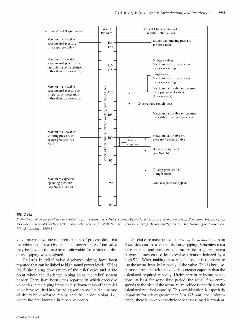
FIG. 7.16a
Definitions of terms used in connection with overpressure relief systems. (Reproduced courtesy of the American Petroleum Institute fromAPI Recommended Practice 520, Sizing, Selection, and Installation of Pressure-relieving Devices in Refineries, Part I—Sizing and Selection,7th ed., January 2000.)
Pressure Vessel RequirementsVessel
PressureTypical Characteristics of
Pressure Relief Valves
Maximum relieving pressurefor fire sizing
Multiple valvesMaximum relieving pressurefor process sizing
Single-valveMaximum relieving pressurefor process sizing
Maximum allowable set pressurefor supplemental valves(fire exposure)
Maximum allowable set pressure for single valve
Closing pressure fora single valve
Maximum allowable set pressurefor additional valves (process)
Overpressure (maximum)
Blowdown (typical)(see Note 6)
Leak test pressure (typical)
Simmer(typical)
Maximum allowableaccumulated pressure(fire exposure only)
Maximum allowableaccumulated pressure formultiple-valve installation(other than fire exposure)
Maximum allowableaccumulated pressure forsingle-valve installation(other than fire exposure)
Maximum allowableworking pressure ordesign pressure (see Note 4)
Maximum expectedoperating pressure (see Notes 5 and 6)
121120
116
115
110
105
100
95
90
85
Perc
ent o
f m
axim
um a
llow
able
wor
king
pre
ssur
e (g
auge
)
© 2003 by Béla Lipták
994
Safety and Miscellaneous Sensors
Reliability, Testing, and Redundancy
The designer may also have to consider the requirementsimposed by the insurance underwriting groups. Because thepurpose of overpressure protection is to prevent the destructionof capital investment and to provide personnel safety, suchconsiderations as toxicity, polymerization, corrosion, and dam-age to other equipment in the plant must also be consideredwhen deciding on the discharge destinations of PRVs.
Because unit downtime and loss of material are both tobe minimized, it is also important that the PRVs provide tightshutoff against maximum operating pressure while it is belowthe set point for actuation. Personnel safety and the minimi-zation of property damage lead to requirements for highreliability, both in terms of accuracy and repeatability.
A pressure-relieving valve in a chemical plant is ratherunique in that it, hopefully, will never need to operate. Fur-thermore, it is also rare that any such system would ever beoperated for test purposes, although certain of its componentsmight be tested periodically. The capability for system testingis usually not provided because of the cost of the added valvesand bypasses that would be needed. Even when such capa-bility is provided, the system test is performed only at ratherlong intervals.
A pressure relief valve is not tested weekly for its conditionas one might test an emergency generator or a fire pump. Weexpect the PRV valve to work when called upon in spite of theextended periods of stagnation while exposed to process fluids,operating temperatures, and operating pressures, plus to the fullrange of ambient conditions. This requirement that the valvework when called upon, coupled with the requirement to protectthe safety of personnel and equipment, drives the designers toconsider redundancy. Such designs are exemplified by duplicateor multiple relief valves, rupture discs plus safety valves, flarevalves backed up by pressure relief valves, etc.
Safety Checklist
Section 7.15 listed and discussed the code requirements andpractices recommended by standards that have been gener-ated by regulating. In addition, the following considerationsand options should be kept in mind:
1. The use of extra safety factors in sizing or rating overand above those established in codes, regulations, andrecommended practices
2. The provision of other protective facilities that mayresult in credits under the codes or regulations
3. The provision of credit for redundancy or other pro-tective facilities, even though such credit may not beclearly established in codes or regulations
4. Preferences, particularly in installation practices,based on operating or maintenance practices
5. The establishment of minimum design pressures forvarious types of equipment in various services (Thiswould affect the pressure-relieving systems in that oper-ating pressure may not always bear the same relationship
to design pressure and smaller relieving valves set atthe minimum design pressure may be suitable.)
6. The relationship between operating pressure andrelief valve set pressure as affected by the upsets tooperating conditions that are acceptable before pres-sure relief occurs
7. The standardization of relieving device sizes andtypes and the standardization of relieving devicemounting nozzle sizes and locations for various typesof equipment in different services
8. The inspection and test procedures established by thecompany for its pressure-relieving systems or thecomponents of those systems
9. The accounting needs and practices of the companyas they might affect flow detection and metering inthe pressure-relieving system or at the valve
10. Noise produced and maximum level of noise allowedin the discharge piping and header, depending on itsdiameter
THE SIZING OF PRVS
Before sizing the pressure relief valve, one must determineif the process material released will be vapor or gas, liquid,or a mixture of liquid and vapor (two-phase). Each of thesecases is separately discussed below.
The design engineer should also remember that PRVsizing programs are available on CDs from the manufacturers.
1
While these programs do save time, it is advisable to fullyunderstand the sizing steps and considerations. For thesereasons, both graphical methods of approximate PRV sizing andaccurate calculations will be described in the following pages.
Backpressure
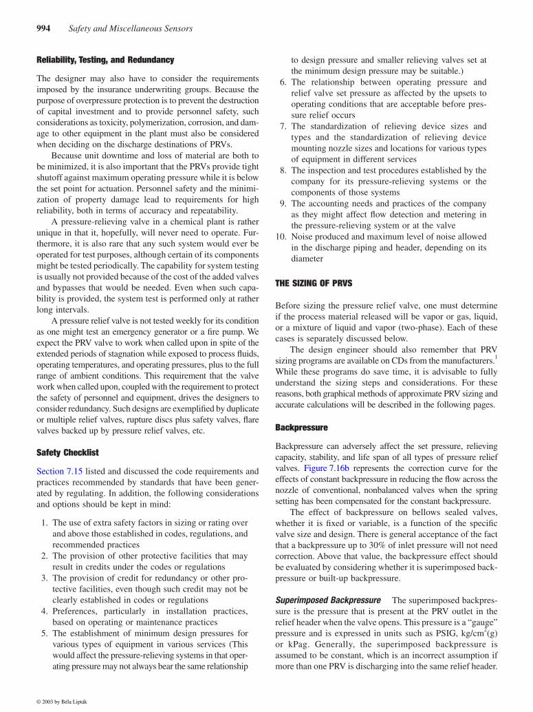
Backpressure can adversely affect the set pressure, relievingcapacity, stability, and life span of all types of pressure reliefvalves. Figure 7.16b represents the correction curve for theeffects of constant backpressure in reducing the flow across thenozzle of conventional, nonbalanced valves when the springsetting has been compensated for the constant backpressure.
The effect of backpressure on bellows sealed valves,whether it is fixed or variable, is a function of the specificvalve size and design. There is general acceptance of the factthat a backpressure up to 30% of inlet pressure will not needcorrection. Above that value, the backpressure effect shouldbe evaluated by considering whether it is superimposed back-pressure or built-up backpressure.
Superimposed Backpressure
The superimposed backpres-sure is the pressure that is present at the PRV outlet in therelief header when the valve opens. This pressure is a “gauge”pressure and is expressed in units such as PSIG, kg/cm
2
(g)or kPag. Generally, the superimposed backpressure isassumed to be constant, which is an incorrect assumption ifmore than one PRV is discharging into the same relief header.
© 2003 by Béla Lipták
7.16 Relief Valves—Sizing, Specification, and Installation
995
In reality, this pressure is variable and is changing as a func-tion of the number of PRVs relieving into the header at anyone time.
As was discussed in Section 7.15, a fire zone has an areaof 2500 to 5000 ft
2
, and a local fire might cause dischargesfrom only one PRV in that area. Similarly, if the cause of theoverpressure condition is a blocked outlet, it too might affectonly one or two PRVs. On the other hand, if the supply ofelectric power, cooling water, instrument air, or steam fails,the failure of such utilities can cause many PRVs to be reliev-ing at the same time, and this, in turn, can cause the superim-posed backpressure in the relief header to rise substantially.
Built-Up Backpressure
The built-up backpressure is thepressure drop between the PRV outlet and the end of thedischarge piping. Therefore, it is the sum of the pressurelosses in the pipe fittings, valves, and the pipe itself. Its unitscan be given in PSI, kg/cm
2
, and kPa. When choke flowoccurs, the built-up pressure can be very high.
The built-up backpressure is a function of the dischargeflow rate, the sizes of the outlet fittings and pipe, the numberof valves and other restrictions, and also by the compress-ibility of the discharging vapors and by temperature. Thebuilt-up backpressure will therefore be lower if the PRV isconnected to a short tail pipe that vents to atmosphere.
Backpressure Effects
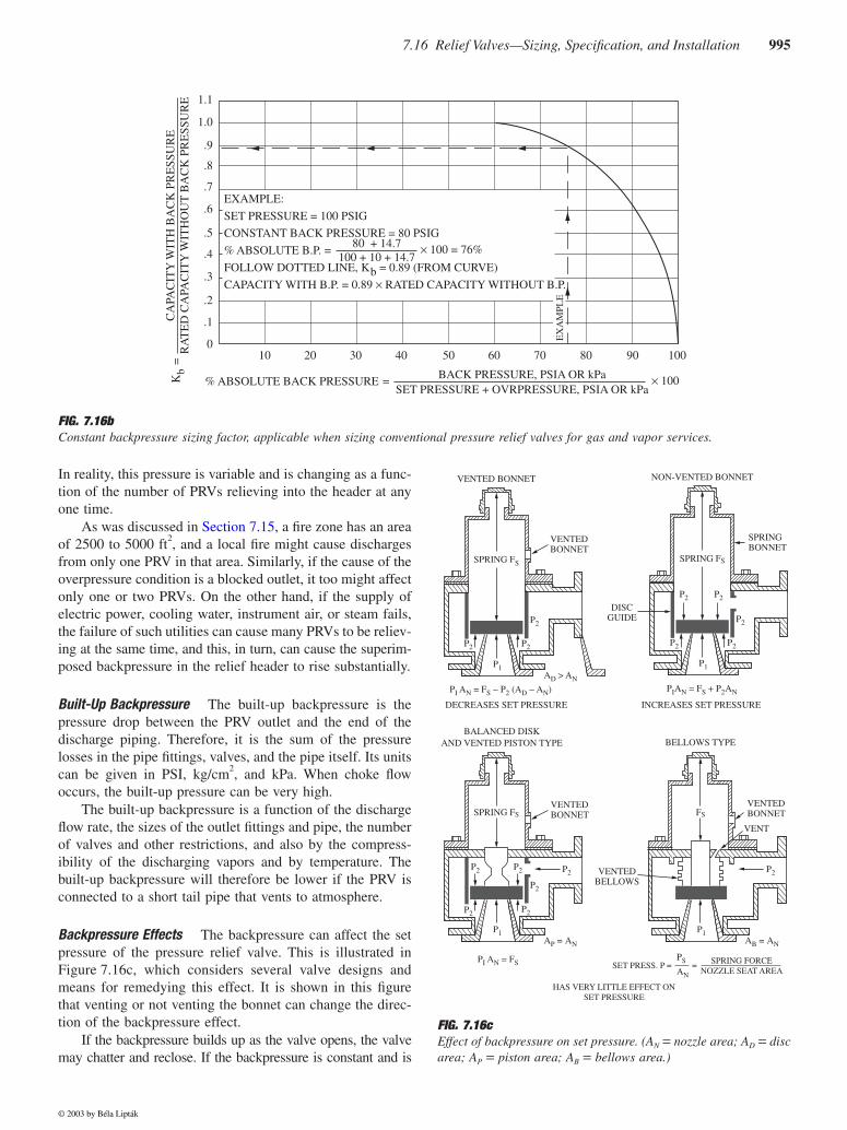
The backpressure can affect the setpressure of the pressure relief valve. This is illustrated inFigure 7.16c, which considers several valve designs andmeans for remedying this effect. It is shown in this figurethat venting or not venting the bonnet can change the direc-tion of the backpressure effect.
If the backpressure builds up as the valve opens, the valvemay chatter and reclose. If the backpressure is constant and is
FIG. 7.16b
Constant backpressure sizing factor, applicable when sizing conventional pressure relief valves for gas and vapor services.
CA
PAC
ITY
WIT
H B
AC
K P
RE
SSU
RE
RA
TE
D C
APA
CIT
Y W
ITH
OU
T B
AC
K P
RE
SSU
RE
Kb
=
1.1
1.0
.9
.8
.7
.6
.5
.4
.3
.2
.1
010 20 30 40 50 60 70 80 90 100
EXAMPLE:
SET PRESSURE = 100 PSIG
CONSTANT BACK PRESSURE = 80 PSIG
% ABSOLUTE B.P. =
FOLLOW DOTTED LINE, Kb = 0.89 (FROM CURVE)
CAPACITY WITH B.P. = 0.89 × RATED CAPACITY WITHOUT B.P.
80 + 14.7100 + 10 + 14.7
× 100 = 76%
% ABSOLUTE BACK PRESSURE =BACK PRESSURE, PSIA OR kPa
SET PRESSURE + OVRPRESSURE, PSIA OR kPa× 100
EX
AM
PLE
FIG. 7.16c
Effect of backpressure on set pressure. (A
N
=
nozzle area; A
D
=
discarea; A
P
=
piston area; A
B
=
bellows area.)
VENTED BONNET
VENTEDBONNET
DISCGUIDE
DECREASES SET PRESSURE INCREASES SET PRESSURE
SPRING FS
P2 P2
P2
P1AD > AN
PI AN = FS − P2 (AD − AN)
NON-VENTED BONNET
SPRINGBONNET
SPRING FS
P2 P2
P2
P2P2
P1
PIAN = FS + P2AN
BALANCED DISKAND VENTED PISTON TYPE BELLOWS TYPE
VENTEDBONNET
VENTEDBELLOWS
SPRING FS
P2 P2
P2P2P2
P2
P1AP = AN
PI AN = FS
VENTEDBONNET
VENT
FS
P2
P1AB = AN
HAS VERY LITTLE EFFECT ONSET PRESSURE
PS
AN
SPRING FORCENOZZLE SEAT AREA
SET PRESS. P = =
© 2003 by Béla Lipták
996
Safety and Miscellaneous Sensors
already present when the valve starts to open, it should be pos-sible (if all code and insurance requirements are fully satisfied)to compensate for it by raising or lowering the spring setting.
In conventional pressure relief valves, constant backpres-sures up to the critical pressure ratio can be compensated byspring setting without affecting the capacity. Above that setting,compensation can be used, but (as will be discussed later) anappropriate capacity reduction factor must be employed insizing. All manufacturers provide this reduction factor, andthere is virtually unanimous agreement on the factor at anygiven ratio of constant backpressure to actual relieving pres-sure for both vapors and liquids.
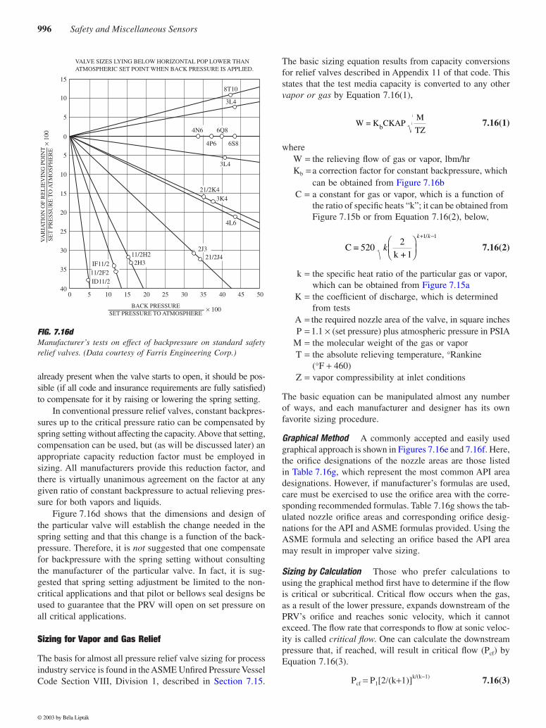
Figure 7.16d shows that the dimensions and design ofthe particular valve will establish the change needed in thespring setting and that this change is a function of the back-pressure. Therefore, it is
not
suggested that one compensatefor backpressure with the spring setting without consultingthe manufacturer of the particular valve. In fact, it is sug-gested that spring setting adjustment be limited to the non-critical applications and that pilot or bellows seal designs beused to guarantee that the PRV will open on set pressure onall critical applications.
Sizing for Vapor and Gas Relief
The basis for almost all pressure relief valve sizing for processindustry service is found in the ASME Unfired Pressure VesselCode Section VIII, Division 1, described in Section 7.15.
The basic sizing equation results from capacity conversionsfor relief valves described in Appendix 11 of that code. Thisstates that the test media capacity is converted to any other
vapor or gas
by Equation 7.16(1),
7.16(1)
whereW
=
the relieving flow of gas or vapor, lbm/hrK
b
=
a correction factor for constant backpressure, which can be obtained from Figure 7.16b
C
=
a constant for gas or vapor, which is a function of the ratio of specific heats “k”; it can be obtained from Figure 7.15b or from Equation 7.16(2), below,
7.16(2)
k
=
the specific heat ratio of the particular gas or vapor, which can be obtained from Figure 7.15a
K
=
the coefficient of discharge, which is determined from tests
A
=
the required nozzle area of the valve, in square inchesP
=
1.1
×
(set pressure) plus atmospheric pressure in PSIAM
=
the molecular weight of the gas or vaporT
=
the absolute relieving temperature,
°
Rankine (
°
F
+
460)Z
=
vapor compressibility at inlet conditions
The basic equation can be manipulated almost any numberof ways, and each manufacturer and designer has its ownfavorite sizing procedure.
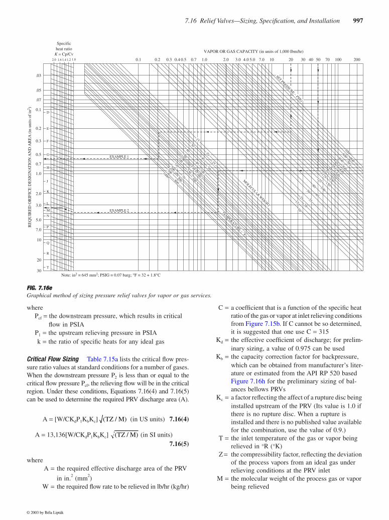
Graphical Method
A commonly accepted and easily usedgraphical approach is shown in Figures 7.16e and 7.16f. Here,the orifice designations of the nozzle areas are those listedin Table 7.16g, which represent the most common API areadesignations. However, if manufacturer’s formulas are used,care must be exercised to use the orifice area with the corre-sponding recommended formulas. Table 7.16g shows the tab-ulated nozzle orifice areas and corresponding orifice desig-nations for the API and ASME formulas provided. Using theASME formula and selecting an orifice based the API areamay result in improper valve sizing.
Sizing by Calculation
Those who prefer calculations tousing the graphical method first have to determine if the flowis critical or subcritical. Critical flow occurs when the gas,as a result of the lower pressure, expands downstream of thePRV’s orifice and reaches sonic velocity, which it cannotexceed. The flow rate that corresponds to flow at sonic veloc-ity is called
critical flow
. One can calculate the downstreampressure that, if reached, will result in critical flow (P
cf
) byEquation 7.16(3).
P
cf
=
P
1
[2
/
(k
+
1)]
k/(k
−
1)
7.16(3)
FIG. 7.16d
Manufacturer’s tests on effect of backpressure on standard safetyrelief valves. (Data courtesy of Farris Engineering Corp.)
VALVE SIZES LYING BELOW HORIZONTAL POP LOWER THANATMOSPHERIC SET POINT WHEN BACK PRESSURE IS APPLIED.
8T10
3L4
3L4
3K4
2J3
2H3
4L6
21/2K4
21/2J411/2H2
IF11/2
ID11/2 11/2F2
6Q84N6
4P6 6S8
15
10
5
5
10
15
20
25
30
35
400 5 10 15 20 25
BACK PRESSURESET PRESSURE TO ATMOSPHERE
30 35 40 45 50
× 100
0
VA
RIA
TIO
N O
F R
EL
IEV
ING
PO
INT
SET
PR
ESS
UR
E T
O A
TM
OSP
HE
RE
× 10
0
W = K CKAPM
TZb
C =2
k + 1520
1 1
kk k
+ −/
© 2003 by Béla Lipták
7.16 Relief Valves—Sizing, Specification, and Installation
997
whereP
cf
=
the downstream pressure, which results in critical flow in PSIA
P
1
=
the upstream relieving pressure in PSIAk
=
the ratio of specific heats for any ideal gas
Critical Flow Sizing
Table 7.15a lists the critical flow pres-sure ratio values at standard conditions for a number of gases.When the downstream pressure P
2
is less than or equal to thecritical flow pressure P
cf
, the relieving flow will be in the criticalregion. Under these conditions, Equations 7.16(4) and 7.16(5)can be used to determine the required PRV discharge area (A).
A
=
[W/CK
d
P
1
K
b
K
c
] (in US units)
7.16(4)
A
=
13,136[W/CK
d
P
1KbKc] (in SI units) 7.16(5)
whereA = the required effective discharge area of the PRV
in in.2 (mm2)W = the required flow rate to be relieved in lb/hr (kg/hr)
C = a coefficient that is a function of the specific heat ratio of the gas or vapor at inlet relieving conditions from Figure 7.15b. If C cannot be so determined, it is suggested that one use C = 315
Kd = the effective coefficient of discharge; for prelim-inary sizing, a value of 0.975 can be used
Kb = the capacity correction factor for backpressure, which can be obtained from manufacturer’s liter-ature or estimated from the API RP 520 based Figure 7.16h for the preliminary sizing of bal-ances bellows PRVs
Kc = a factor reflecting the affect of a rupture disc being installed upstream of the PRV (Its value is 1.0 if there is no rupture disc. When a rupture is installed and there is no published value available for the combination, use the value of 0.9.)
T = the inlet temperature of the gas or vapor being relieved in °R (°K)
Z = the compressibility factor, reflecting the deviation of the process vapors from an ideal gas under relieving conditions at the PRV inlet
M = the molecular weight of the process gas or vapor being relieved
FIG. 7.16eGraphical method of sizing pressure relief valves for vapor or gas services.
RE
QU
IRE
D O
RIF
ICE
DE
SIG
NA
TIO
N A
ND
AR
EA
(in
uni
ts o
f in
2 )
30
20
10
7.0
5.0
3.0
2.0
1.0
0.7
0.5
0.3
0.2
0.1
.07
.05
.03
T
R
Q
P
N
M
L
K
J
H
G
F
E
D
2.0 1.6 1.4 1.2 1.0 0.1 0.2 0.3 0.4 0.5 0.7 1.0 2.0 3.0 4.0 5.0 7.0 10 20 30 40 50 70 200100
EXAMPLE 2
EXAMPLE 1
VAPOR OR GAS CAPACITY (in units of 1,000 Ibm/hr)
Specificheat ratio
K = Cp/Cv
Note: in2 = 645 mm2; PSIG = 0.07 barg; °F = 32 + 1.8°C
1000
1000
800
300
500
200
350
200
250
120
100
150
200
250
300
400
500
700
900
125
175
225275
350
450
600
800
140
160
100
60
80
30
40
50
15
20
70
25
10
15
25
50
80
20
35
60
300
SET PRESSURE − PSIG
MOLECULAR W
EIGHT
TEMPERATURE − °F
(TZ / M)
(TZ / M)
© 2003 by Béla Lipták
998 Safety and Miscellaneous Sensors
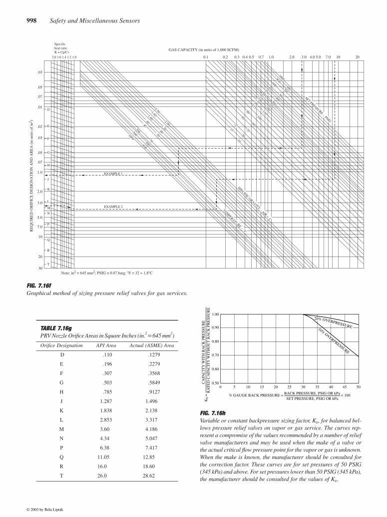
FIG. 7.16fGraphical method of sizing pressure relief valves for gas services.
RE
QU
IRE
D O
RIF
ICE
DE
SIG
NA
TIO
N A
ND
AR
EA
(in
uni
ts o
f in
2 )
.03
.05
.07
.01
.02
.03
.05
.07
1.0
2.0
3.0
5.0
7.0
10
20
30
D
H
J
K
L
M
N
P
Q
R
T
Specificheat ratioK = Cp/Cv
2.0 1.6 1.4 1.2 1.0 0.1 0.2 0.3 0.4 0.5 0.7 1.0 2.0 3.0 4.0 5.0 7.0 10 20
Note: in2 = 645 mm2; PSIG = 0.07 barg: °F = 32 + 1.8°C
GAS CAPACITY (in units of 1,000 SCFM)
EXAMPLE 2
EXAMPLE 1
1000
1000
800
100
125150
175200
225250
275
300
350
400
450
500
600700
800
900
300
200
.40
.50
.80
.60
1.00
1.60
2.50
2.001.20
70 10
15
25
50
80
20
35
60
500
E
F
G
SPECIFIC GRAVITY − AIR = 1
SET PRESSURE − PSIG
TEMPERATURE − °F
TABLE 7.16gPRV Nozzle Orifice Areas in Square Inches (in.2 = 645 mm2)
Orifice Designation API Area Actual (ASME) Area
D .110 .1279
E .196 .2279
F .307 .3568
G .503 .5849
H .785 .9127
J 1.287 1.496
K 1.838 2.138
L 2.853 3.317
M 3.60 4.186
N 4.34 5.047
P 6.38 7.417
Q 11.05 12.85
R 16.0 18.60
T 26.0 28.62
FIG. 7.16hVariable or constant backpressure sizing factor, Kb, for balanced bel-lows pressure relief valves on vapor or gas service. The curves rep-resent a compromise of the values recommended by a number of reliefvalve manufacturers and may be used when the make of a valve orthe actual critical flow pressure point for the vapor or gas is unknown.When the make is known, the manufacturer should be consulted forthe correction factor. These curves are for set pressures of 50 PSIG(345 kPa) and above. For set pressures lower than 50 PSIG (345 kPa),the manufacturer should be consulted for the values of Kb.
0 5 10 15 20 25 30 35 40 45 50
% GAUGE BACK PRESSURE = BACK PRESSURE, PSIG OR kPa × 100 SET PRESSURE, PSIG OR kPa K
b =
C
APA
CIT
Y W
ITH
BA
CK
PR
ESS
UR
E
RA
TE
D C
APA
CIT
Y W
ITH
OU
T B
AC
K P
RE
SSU
RE
1.00
0.90
0.80
0.70
0.60
0.50
10% OVERPRESSURE
20% OVERPRESSURE
© 2003 by Béla Lipták
7.16 Relief Valves—Sizing, Specification, and Installation 999
P1 = (for conventional PRVs) the set pressure × (1 + accumulation allowed by code having jurisdic-tion) + atmospheric pressure in PSIA (kPaa); (for pilot-operated PRV valves) = the set pressure plus accumulation minus ∆Pinlet in PSIA (kPaa)
∆Pinlet = the inlet pipe loss upstream to the PRV in PSI (kPa)
Subcritical Flow Sizing If the PRV is provided with bel-lows seals, the sizing for subcritical flow can be based onEquation 7.16(4) or 7.16(5), but the backpressure correctionfactor Kb should consider the subcritical flow and the tendencyof the disc of the PRV to drop to below full lift. For these reasons,the Kb factor should be obtained from the manufacturer.
When sizing conventional or pilot-operated PRVs forsubcritical conditions (P2 > Pcf), Equation 7.16(6) or 7.16(7)should be used.
A = [W/735F2KdKc] (in US units)
7.16(6)
A = 17.9[W/F2KdKc] (in SI units)
7.16(7)
whereF2 = the subcritical flow coefficient
Backpressure Effect on Capacity Backpressure affects thecapacity and thus the sizing of relieving devices. In a sense,the PRV is similar to an open control valve, because itsupstream pressure is the process pressure, and its downstreampressure is that which exists in the relieving header. However,instead of being a controlling element, it is controlled by thepressure conditions at its inlet and outlet.
Most safety valves will handle flow very similar to atheoretical nozzle as long as they are fully open (at full lift)so that the controlling flow area is established by the nozzle.The capacity of a theoretical nozzle is not affected by thedownstream pressure as long as it does not rise to the pointwhere the ∆P drops below the critical pressure drop neededto maintain sonic flow. At higher backpressures, the flowbecomes subsonic.
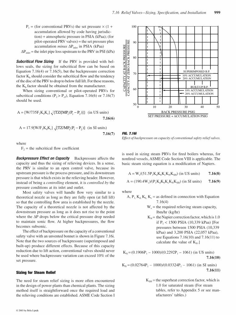
The effect of backpressure on the capacity of a conventionalsafety valve with an unvented bonnet is shown in Figure 7.16i.Note that the two sources of backpressure (superimposed andbuilt-up) produce different effects. Because of this capacityreduction due to lift action, conventional valves should neverbe used where backpressure variation can exceed 10% of theset pressure.
Sizing for Steam Relief
The need for steam relief sizing is more often encounteredin the design of power plants than chemical plants. The sizingmethod itself is straightforward once the required load andthe relieving conditions are established. ASME Code Section I
is used in sizing steam PRVs for fired boilers whereas, fornonfired vessels, ASME Code Section VIII is applicable. Thebasic steam sizing equation is a modification of Napiers.
A = Ws/(51.5P1KdKbKcKNKSH) (in US units) 7.16(8)
A = (190.4Ws)/(P1KdKbKcKNKSH) (in SI units) 7.16(9)
whereA, P1, Kd, Kb, Kc = as defined in connection with Equation
7.16(4)Ws = the required relieving steam capacity,
lbm/hr (kg/hr)KN = the Napier correction factor, which is 1.0
if P1 < 1500 PSIA (10,339 kPaa) [For pressures between 1500 PSIA (10,339 kPaa) and 3,200 PSIA (22,057 kPaa), use Equations 7.16(10) and 7.16(11) to calculate the value of KN.]
KN = (0.1906P1 – 1000)/(0.2292P1 – 1061) (in US units) 7.16(10)
KN = (0.02764P1 – 1000)/(0.03324P1 – 1061) (in SI units)7.16(11)
KSH = the superheat correction factor, which is 1.0 for saturated steam (For steam tables, refer to Appendix 5 or see man-ufacturers’ tables.)
{ /[ ( )]}TZ MP P P1 1 2−
[TZ MP P P/ ( )]1 1 2−FIG. 7.16iEffect of backpressure on capacity of conventional safety relief valves.
CA
PAC
ITY
AT
BA
CK
PR
ESS
UR
E
CA
PAC
ITY
AT
ZE
RO
BA
CK
PR
ESS
UR
E
SUPERIMPOSED B.P.
10% ACCUMULATION 20% ACCUMULATION
BUILT-UP B.P.10% ACCUMULATION 20% ACCUMULATION
0 10 20 30 40 50
100
90
80
70
60
50
BACK PRESSURE PSIGSET PRESSURE + ACCUMULATION PSIG
© 2003 by Béla Lipták
1000 Safety and Miscellaneous Sensors
Sizing for Liquid Relief
The 1986 edition of ASME UG-131 requires that, for pres-sure relief valves on incompressible fluid service, a capacitycertification test using water at a temperature between 40 and125°F be conducted. For any other fluid, the manufacturer’stables generally can be used as long as the equivalent watervolumetric rate in gpm is used to enter these tables.
Division I of the ASME Code Section VIII, since 1980,has required that liquid service PRVs be provided with capac-ity certification. This certification requires that the rated coef-ficient of discharge be based on 10% overpressure. ExistingPRVs that were manufactured before 1980, were not providedwith certification, but were sized with 25% overpressureallowance need not be replaced, but new PRVs must bedesigned for 10% overpressure operation.
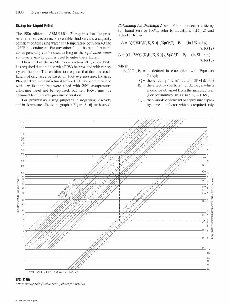
For preliminary sizing purposes, disregarding viscosityand backpressure effects, the graph in Figure 7.16j can be used.
Calculating the Discharge Area For more accurate sizingfor liquid service PRVs, refer to Equations 7.16(12) and7.16(13) below:
A = [Q/(38KdKwKcKv)] (in US units)
7.16(12)
A = [(11.78Q)/(KdKwKcKv)] (in SI units)
7.16(13)
whereA, KcP1, P2 = as defined in connection with Equation
7.16(4)Q = the relieving flow of liquid in GPM (l/min)
Kd = the effective coefficient of dicharge, whichshould be obtained from the manufacturer(For preliminary sizing use Kd = 0.65.)
Kw = the variable or constant backpressure capac-ity correction factor, which is required only
SpG P P/( 1 2−
SpG P P/( 1 2−
FIG. 7.16jApproximate relief valve sizing chart for liquids.
2000
1500
1000
800700600500
400
300
200
150
100
LIQ
UID
CA
PAC
ITY
(in
uni
ts o
f G
PM)
40
T30
20
10
8
65
4
3
2
10
8
65
4
3
2
.10D
E
F
G
H
J
K
L
MN
P
Q
R
.08
.06
.05
.04
.03
RE
QU
IRE
D O
RIF
ICE
DE
SIG
NA
TIO
N A
ND
AR
EA
(in
uni
ts o
f in
2 )
80706050
40
30
20
15
10
8765
4
3
2
1
GPM = 3.78 Ipm; PSIG = 0.07 barg: in2 = 647 mm2
GAUGE PRESSURE —
PSIG
2500
1500
2000
1000
800
400
500
300
200
100
250
150
75
35
50
25
15
20
10
1.40
1.20
SPECIFIC
GRAVIT
Y —W
ATER = 1
1.00
.50
.60
.80
.40
600
© 2003 by Béla Lipták
7.16 Relief Valves—Sizing, Specification, and Installation 1001
for bellows sealed PRV valves (Figure 7.16k)(For conventional or pilot-operated valves,or when the backpressure is atmospheric,use Kw = 1.0.)
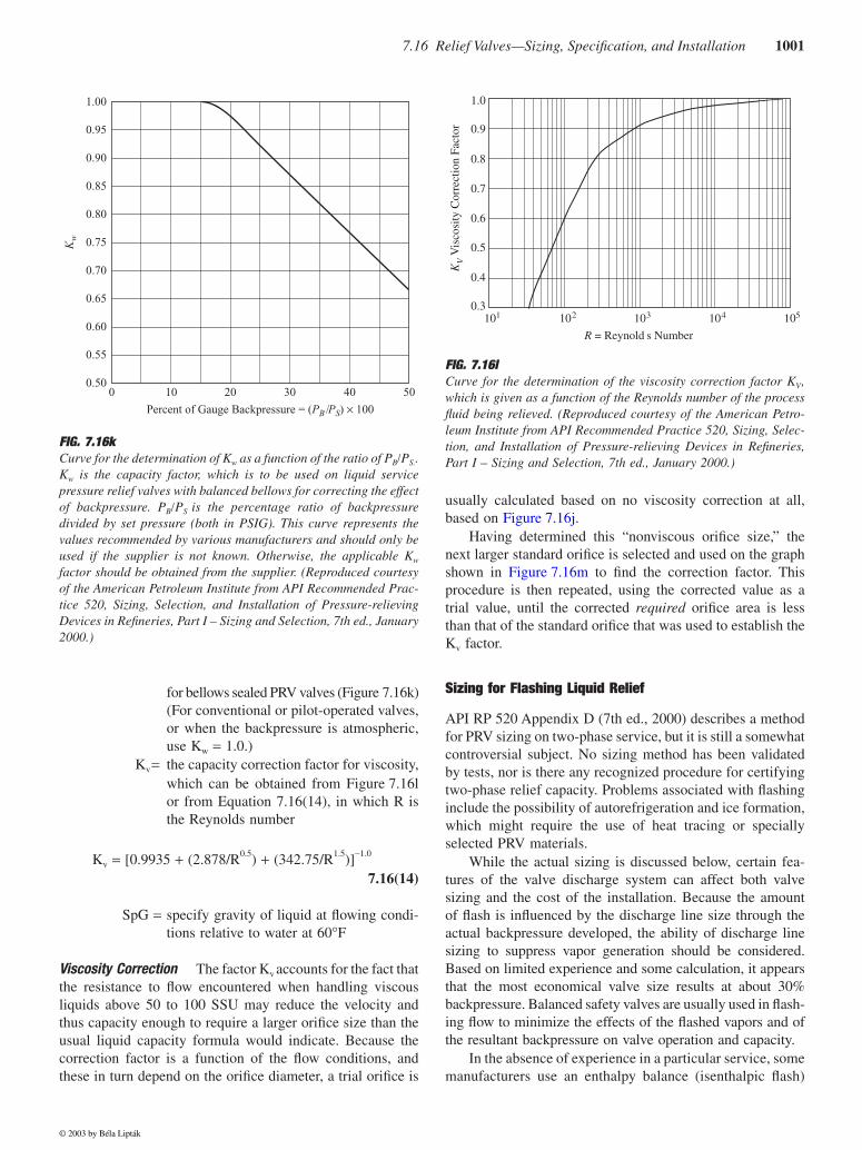
Kv = the capacity correction factor for viscosity,which can be obtained from Figure 7.16lor from Equation 7.16(14), in which R isthe Reynolds number
Kv = [0.9935 + (2.878/R0.5) + (342.75/R1.5)]−1.0
7.16(14)
SpG = specify gravity of liquid at flowing condi-tions relative to water at 60°F
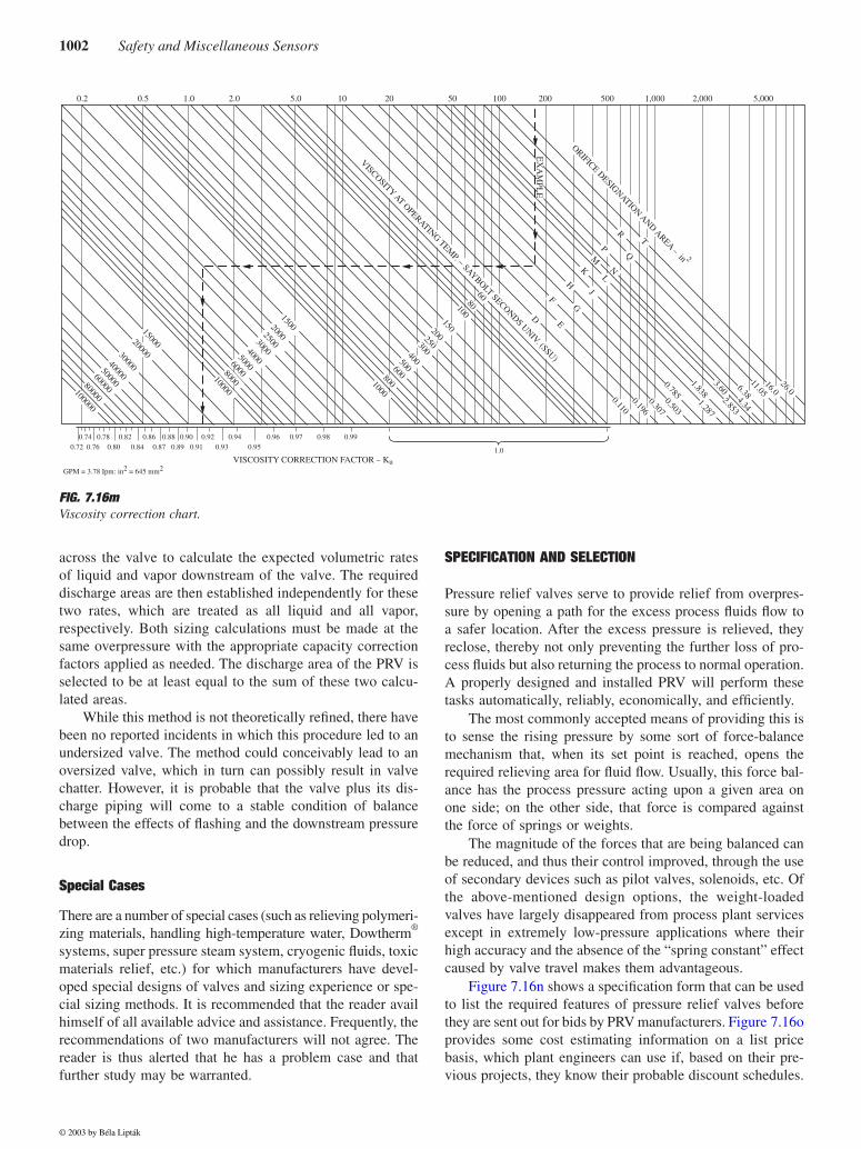
Viscosity Correction The factor Kv accounts for the fact thatthe resistance to flow encountered when handling viscousliquids above 50 to 100 SSU may reduce the velocity andthus capacity enough to require a larger orifice size than theusual liquid capacity formula would indicate. Because thecorrection factor is a function of the flow conditions, andthese in turn depend on the orifice diameter, a trial orifice is
usually calculated based on no viscosity correction at all,based on Figure 7.16j.
Having determined this “nonviscous orifice size,” thenext larger standard orifice is selected and used on the graphshown in Figure 7.16m to find the correction factor. Thisprocedure is then repeated, using the corrected value as atrial value, until the corrected required orifice area is lessthan that of the standard orifice that was used to establish theKv factor.
Sizing for Flashing Liquid Relief
API RP 520 Appendix D (7th ed., 2000) describes a methodfor PRV sizing on two-phase service, but it is still a somewhatcontroversial subject. No sizing method has been validatedby tests, nor is there any recognized procedure for certifyingtwo-phase relief capacity. Problems associated with flashinginclude the possibility of autorefrigeration and ice formation,which might require the use of heat tracing or speciallyselected PRV materials.
While the actual sizing is discussed below, certain fea-tures of the valve discharge system can affect both valvesizing and the cost of the installation. Because the amountof flash is influenced by the discharge line size through theactual backpressure developed, the ability of discharge linesizing to suppress vapor generation should be considered.Based on limited experience and some calculation, it appearsthat the most economical valve size results at about 30%backpressure. Balanced safety valves are usually used in flash-ing flow to minimize the effects of the flashed vapors and ofthe resultant backpressure on valve operation and capacity.
In the absence of experience in a particular service, somemanufacturers use an enthalpy balance (isenthalpic flash)
FIG. 7.16kCurve for the determination of Kw as a function of the ratio of PB/PS..Kw is the capacity factor, which is to be used on liquid servicepressure relief valves with balanced bellows for correcting the effectof backpressure. PB/PS is the percentage ratio of backpressuredivided by set pressure (both in PSIG). This curve represents thevalues recommended by various manufacturers and should only beused if the supplier is not known. Otherwise, the applicable Kw
factor should be obtained from the supplier. (Reproduced courtesyof the American Petroleum Institute from API Recommended Prac-tice 520, Sizing, Selection, and Installation of Pressure-relievingDevices in Refineries, Part I – Sizing and Selection, 7th ed., January2000.)
1.00
0.95
0.90
0.85
0.80
Kw 0.75
0 10 20
Percent of Gauge Backpressure = (PB /PS) × 100
30 40 50
0.70
0.65
0.60
0.55
0.50
FIG. 7.16lCurve for the determination of the viscosity correction factor KV,which is given as a function of the Reynolds number of the processfluid being relieved. (Reproduced courtesy of the American Petro-leum Institute from API Recommended Practice 520, Sizing, Selec-tion, and Installation of Pressure-relieving Devices in Refineries,Part I – Sizing and Selection, 7th ed., January 2000.)
1.0
0.9
0.8
0.7
0.6
0.5
0.4
0.3101 102 103
R = Reynold s Number
104 105
KV V
isco
sity
Cor
rect
ion
Fact
or
© 2003 by Béla Lipták
1002 Safety and Miscellaneous Sensors
across the valve to calculate the expected volumetric ratesof liquid and vapor downstream of the valve. The requireddischarge areas are then established independently for thesetwo rates, which are treated as all liquid and all vapor,respectively. Both sizing calculations must be made at thesame overpressure with the appropriate capacity correctionfactors applied as needed. The discharge area of the PRV isselected to be at least equal to the sum of these two calcu-lated areas.
While this method is not theoretically refined, there havebeen no reported incidents in which this procedure led to anundersized valve. The method could conceivably lead to anoversized valve, which in turn can possibly result in valvechatter. However, it is probable that the valve plus its dis-charge piping will come to a stable condition of balancebetween the effects of flashing and the downstream pressuredrop.
Special Cases
There are a number of special cases (such as relieving polymeri-zing materials, handling high-temperature water, Dowtherm®
systems, super pressure steam system, cryogenic fluids, toxicmaterials relief, etc.) for which manufacturers have devel-oped special designs of valves and sizing experience or spe-cial sizing methods. It is recommended that the reader availhimself of all available advice and assistance. Frequently, therecommendations of two manufacturers will not agree. Thereader is thus alerted that he has a problem case and thatfurther study may be warranted.
SPECIFICATION AND SELECTION
Pressure relief valves serve to provide relief from overpres-sure by opening a path for the excess process fluids flow toa safer location. After the excess pressure is relieved, theyreclose, thereby not only preventing the further loss of pro-cess fluids but also returning the process to normal operation.A properly designed and installed PRV will perform thesetasks automatically, reliably, economically, and efficiently.
The most commonly accepted means of providing this isto sense the rising pressure by some sort of force-balancemechanism that, when its set point is reached, opens therequired relieving area for fluid flow. Usually, this force bal-ance has the process pressure acting upon a given area onone side; on the other side, that force is compared againstthe force of springs or weights.
The magnitude of the forces that are being balanced canbe reduced, and thus their control improved, through the useof secondary devices such as pilot valves, solenoids, etc. Ofthe above-mentioned design options, the weight-loadedvalves have largely disappeared from process plant servicesexcept in extremely low-pressure applications where theirhigh accuracy and the absence of the “spring constant” effectcaused by valve travel makes them advantageous.
Figure 7.16n shows a specification form that can be usedto list the required features of pressure relief valves beforethey are sent out for bids by PRV manufacturers. Figure 7.16oprovides some cost estimating information on a list pricebasis, which plant engineers can use if, based on their pre-vious projects, they know their probable discount schedules.
FIG. 7.16mViscosity correction chart.
200003000040000
50000
6000080000
100000
15000
200025003000400050006000800010000
1500
150100
8060
R
T
ORIFICE DESIGNATION AND AREA − in 2
EX
AM
PLE
VISCOSITY AT OPERATING TEMP. − SAYBOLT SECONDS UNIV. (SSU)
16.0
11.05
6.384.34
3.602.853
1.8381.287
0.7850.503
0.307
0.196
0.110
26.0
Q
PM
NL
KJ
HG
FE
D
2002503004005006008001000
0.74 0.78 0.82 0.86 0.88 0.90 0.92 0.940.95
VISCOSITY CORRECTION FACTOR − Ku
0.2 0.5 1.0 2.0 5.0 10 20 50 100 200 500 1,000 2,000 5,000
0.930.910.890.870.840.800.760.720.96 0.97 0.98
GPM = 3.78 Ipm: in2 = 645 mm2
0.99
1.0
© 2003 by Béla Lipták

7.16 Relief Valves—Sizing, Specification, and Installation 1003
FIG. 7.16nPressure relief valve specification form.
PRESSURE RELIEF VALVESSHEET
SPEC. NO.
NO BY DATE REVISION
REV.
CONTRACT DATE
REQ.
BY CHK’D APPR.
P.O.
OF
Tag Number1.
Service2.
Line No./Vessel No.3.Full Nozzle/Semi Nozzle4.Safety or Relief5.Conv., Bellows, Pilot Op.6.Bonnet Type7.Size: Inlet Outlet8.Flange Rating or Screwed9.Type of Facing10.Body and Bonnett11.Seat and Disc12.Resilient Seat Seal13.Guide and Rings14.Spring15.Bellows16.
17.
Cap: Screwed or Bolted18.Lever: Plain or Packed19.Test Gag20.
21.22.23.
Code24.Fire25.
26.27.
Fluid and State28.Required Capacity29.Mol. Wt. Oper. sp. gr.30.Oper. Press. Set Press.31.Oper. Temp. Rel. Temp.32.
Constant33.Back Pressure Variable34.
% Allowable Overpressure36.Overpressure Factor37.Compressibility Factor38.Latent Heat of Vaporization39.Ratio of Specific Heats40.Operating Viscosity41.Barometric Pressure42.
Calc. Area sq. in.45.Selected Area46.Orifice Designation47.Manufacturer48.Model No.
Notes:
FLUID DATA
BASIS
OPTIONS
MATERIALS
CONN.
GENERAL
49.
43.44.
Total35.
© 2003 by Béla Lipták
1004 Safety and Miscellaneous Sensors
Conventional PRVs
As it is shown in Figure 7.16p, the conventional PRV is aforce balance device that is held closed by a spring when theinlet pressure is below its set pressure. When the set pressureis reached, the upward force overcomes that of the spring,and the valve opens. When the inlet pressure drops below theset pressure by some percentage (this difference is calledblowdown), the valve recloses. The housing of the spring isvented to the outlet of the PRV, and therefore the operationof the valve is directly affected by the backpressure.
The main difference in the operation of a PRV on liquidrelief service from that of a vapor relief valve is that it doesnot have “pop action.” This is because, on liquid service, theforce that lifts the disc is generated by the reactive forces(the impact of the flowing liquid stream on the disc holder)to achieve full lift. These reactive forces build slowly duringthe initial 2 to 4% of overpressure, and only after that willthe valve suddenly surge to full lift. The blowdown (thepercentage by which the inlet pressure has to drop below theset pressure for the valve to close) on liquid service is muchlarger than on gas service—around 20%.
PRV Bodies and Bonnets The basic requisite for a directspring-loaded pressure-relieving valve is a suitable valve body,which is usually an angle-type device, having an inlet connec-tion that is suitable for the inlet pressure/temperature require-ments under both normal and relieving conditions. The body,
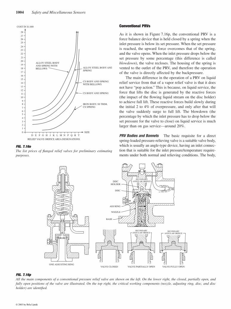
FIG. 7.16oThe list prices of flanged relief valves for preliminary estimatingpurposes.
COST IN $1.000
28
272625
2423
22
20
19
18
17
16
15
14
13
12
10
98
765
4
32
1
0
11
21
ALLOY STEEL BODY ANDSPRING
ALLOY STEEL BODYAND SPRING WITHBELLOWS
CS BODY AND SPRINGWITH BELLOWS
CS BODY AND SPRING
IRON BODY, SS TRIM,CS SPRING
D E F G H J K L M
RELIEF VALVE ORIFICE AREA DESIGNATIONS
N P Q R TSIZE
FIG. 7.16pAll the main components of a conventional pressure relief valve are shown on the left. On the lower right, the closed, partially open, andfully open positions of the valve are illustrated. On the top right, the critical working components (nozzle, adjusting ring, disc, and discholder) are identified.
SECONDARYANNULAR ORIFICE
SECONDARYANNULAR ORIFICEDISC
HOLDER
DISC
ADJ RING
NOZZLE
BASE
VALVE FULLY OPENVALVE PARTIALLY OPENVALVE CLOSEDONE ADJUSTING RING
SECONDARYANNULAR ORIFICE
© 2003 by Béla Lipták
7.16 Relief Valves—Sizing, Specification, and Installation 1005
the outlet, and the bonnet are usually designed for a lowerpressure than the process pipeline or the inlet connection ofthe PRV. Body connections can be flanged, screwed, or welded.
The bonnet is sized to accommodate the spring for themaximum pressure rating of the valve. The bonnet is usedwhen the discharging medium must be confined within thevalve body and discharge piping. All bonnet-type valves haveeither caps over the adjusting bolt or lifting levers, eitherplain or packed.
Flanged valves for steam boilers usually have an openspring with a yoke in place of a closed bonnet. The springis exposed on the steam valve, whereas the spring is totallyenclosed on the bonnet type valve. Marine boiler valves areof the yoke type except that additional cover plates must beadded and sealed to prevent tampering with the spring. Thecovers are vented (not pressure tight).
Seat and Spring The PRV inlet incorporates a valve seatwith a disc for full closure of the inlet port. The disc is usuallyspring loaded, and the spring force is applied directly on thedisc by means of a stem. The disc may be either disc guidedor top guided. A bottom (disc)-guided valve has vanes orfeathers for guiding in the valve bore (inlet port). Processvalve are usually top guided (Figure 7.16p). Boiler valvesand liquid relief valves are often disc guided.
The set pressure is determined by the selection of theproper spring and by adjusting the bolt that compresses thespring to the correct opening pressure. Springs are classed indifferent ranges so that the spring is never overstressed andso that proper clearance between the coils allows for full lift.The spring force at open position must not exceed the liftingforce of the flowing medium when the valve is fully open.The spring setting may be adjustable in a narrow range. Thisadjustment can be 30% or more on low-range springs and5% on higher-range springs. The manufacturer must be con-sulted for the acceptable range for a particular spring.
Nozzles and Blowdown Rings The inlet of the PRV may bedescribed as a bushing, semi-nozzle, or full nozzle. The bush-ing is used on bottom-guided valves. The semi-nozzle isusually found in cast iron valves. Both are screwed into thePRV’s body. The full nozzle is utilized on steel valves andis the part of the valve that is designed for the pressure ratingof the process line.
The seat, orifice, and flange facing is one piece. Theflange of the valve is used for bolting force, which is to ASAstandards. The nozzle flange construction is similar to a VanStone-type flange. The discharge area or orifice of a nozzletype valve is smaller than the nominal inlet. The convergingof the nozzle results in a high velocity, which provides thehigh kinetic energy required to obtain high lift.
Pop Action The capacity of PRVs must be accurately cal-culated, and their action must be reliable and foolproof overthe long run. Reliability is achieved by the maximum use ofsimple mechanisms such as springs and linkages, and so
forth. Accuracy in relieving capacity is achieved by conser-vatism, by treating the relief device as an orifice, and byattempting to size and install it so that it can always releasethe process fluid (and thus energy).
In Figure 7.16p, one should note that there is an adjust-able ring around the nozzle. Furthermore, the disc has eithera fixed or adjustable deflecting lip. The purpose of this lip isto form a huddling chamber, which provides the pop actionof these pressure relief valves. The inlet nozzle is used toefficiently generate the required velocity head (and thuscapacity), while the lip and the ring on the nozzle form asecondary orifice and a device for reconversion of this veloc-ity energy into static pressure to provide the pop action whensufficient vapor flow develops.
Valve Lift and Capacity Being spring-loaded, PRVs requiresome increase in force, because the movement of the springoccurs while the valve is opening. The amount of this forceincrease is determined by the spring constant and by theamount of valve lift required to achieve full capacity. MostPRVs reach their full capacity opening at about 3% abovetheir set pressure. If the pressure rises further, the area ofopening does not increase, so the increase in PRV capacityis the result only of increased valve pressure differential.
Therefore, at 3% overpressure, the valve has fully lifted.At this point, the curtain or cylinder area (huddling chamber)between nozzle and disc is greater than the cross-sectionalarea of the nozzle. The so-called low-lift valves gain morecapacity at higher pressure, because they have not reachedtheir limiting dimensions for the curtain area at the lowoverpressures. In such cases, it is not permitted under theASME Code to calculate down-ratings for valves at lowerpressure based on performance at a higher test pressure,although up-rating above test pressure is permitted, becauseit will always tend to be quite conservative.
In contrast to gas or vapor PRVs, liquid service reliefvalves generally do not reach their full capacity dimensionsuntil their full nominal rating overpressure of 10% is reached.In liquid PRVs designed prior to 1980, this overpressure was25%. Down-rating to lower pressures is permitted and pro-vided by all manufacturers. It is important to understand anddesign for this up-rating and down-rating, especially whenconsidering actual flow during maximum relief. This canaffect pressure losses in inlet and outlet piping.
Balanced PRVs
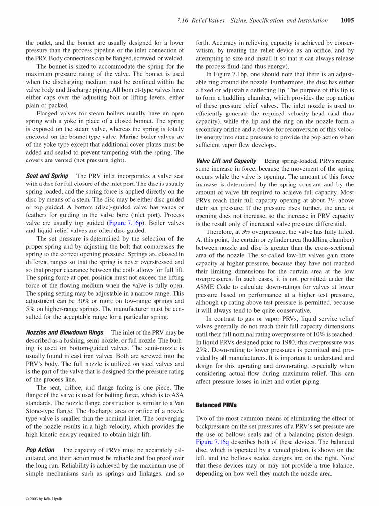
Two of the most common means of eliminating the effect ofbackpressure on the set pressures of a PRV’s set pressure arethe use of bellows seals and of a balancing piston design.Figure 7.16q describes both of these devices. The balanceddisc, which is operated by a vented piston, is shown on theleft, and the bellows sealed designs are on the right. Notethat these devices may or may not provide a true balance,depending on how well they match the nozzle area.
© 2003 by Béla Lipták
1006 Safety and Miscellaneous Sensors
The backpressure effect on the PRV’s set pressure hasalready been discussed in connection with Figure 7.16c. Thisfigure illustrated several valve designs and four differentmeans of remedying this effect. On the lower right,Figure 7.16c illustrates a PRV that is provided with ventedbellows seals. In this design, if the bellows area (AB) is thesame as the nozzle area (AN) of the PRV, the valve will bebalanced, and the backpressure will have no effect on thepressure set point at which the valve opens. Such a balancedPRV is shown on the upper right of Figure 7.16q.
If the bellows area (AB) is not the same as the nozzlearea (AN), the valve will be unbalanced, and the backpressurewill affect the set point. Even among balanced bellowsdesigns, there are differences among the Kb correction factorsof different manufacturers (Figure 7.16r). These variationsare a function of the specific valve design.
Equations 7.16(4) and 7.16(5) should be used when siz-ing balanced bellows PRVs for gas or vapor service. In theseequations, the backpressure correction factor Kb serves tocorrect for the loss in capacity resulting from subcritical flowand for the condition when the valve disc does not lift fully.For preliminary sizing estimates, Figure 7.16b can be used toobtain a Kb correction factor, but, because each manufacturer’sPRV design is a little different, the actual value of Kb shouldbe eventually obtained from the selected manufacturer.
When sizing the PRV for liquid service, it is commonpractice to use the minimum pressure drop in the standardformula [Equation 7.16(12) or 7.16(13)], which includes theKw factor for backpressure correction. For liquid applicationsas well, there is variation in this factor among vendors.
As was shown by Equation 7.16(14), viscous materialsadversely affect the capacity of relief valves. Because therequired correction depends on the Reynolds number, thepoint at which a correction is required will be a function oforifice size, flow rate, and flowing viscosity (Figure 7.16l).There is reasonably good agreement among manufacturers asto the viscosity correction, and there is also general agreementthat viscosities below 50 to 100 SSU do not require correction.
Pilot-Operated PRVs
The pilot-operated PRV shown in Figure 7.16s consists of anunbalanced floating piston type main valve and an externalor integral pilot. During normal operation, because the areaof the piston is larger on the top than on the bottom, andbecause both are exposed to the same process pressure, theresulting net force holds the PRV tightly closed. As the pro-cess pressure rises, the seating force increases with it. Thisfeature is an advantage in applications in which the maximumoperating pressure is close to the relief set pressure and it isimportant to prevent leakage.
When the set point is reached, the pilot vents the pressurefrom the top of the piston, and the piston lifts. When theprocess pressure drops below the set point of the pilot, itcloses its vent, which, in turn, reseats the piston.
The pilot can be pop-action or modulating and can beflowing or nonflowing. The modulating design can saveexpensive process fluids and can shorten the system recoverytime by relieving only as much process fluid as needed tolower the pressure below its set point. For most servicesexcept for inert gases, the nonflowing designs are preferred.
FIG. 7.16qBalancing devices include balancing pistons (on the left) and bel-lows seal (on the right), which can be placed on either balanced(top) or unbalanced (bottom) relief valves.
BONNETMUST
BEVENTED
BELLOWS DETAIL-BALANCED SAFETY
RELIEF VALVE
SAFETY RELIEF VALVEWITH BALANCED DISCAND VENTED PISTON
BELLOWS DETAIL-UNBALANCED SAFETY
RELIEF VALVE
FIG. 7.16rBackpressure capacity reduction factor (Kb) for balanced bellowsPRV valves.
1.00
.90
.80
.70
.60
.50
.40
.30
.20
.10
10 20 30 40 50 60 70 800
A-100 PSIG (690 kPa)
B-100 PSIG (690 kPa)
A-100 PSIG (690 kPa)A-10 PSIG (69 kPa)
B-11.19 PSIG (77.21 kPa)
A-10 PSIG (69 kPa)MANUFACTURER A — 20% OVERPRESSURE
MANUFACTURER A — 10% OVERPRESSURE
MANUFACTURER B — 10% OVERPRESSURE
MANUFACTURER C — 10% OVERPRESSURE
C-100 PSIG
% BACKPRESSURE = ×BACKPRESSURE
SET PRESSURE100
© 2003 by Béla Lipták
7.16 Relief Valves—Sizing, Specification, and Installation 1007
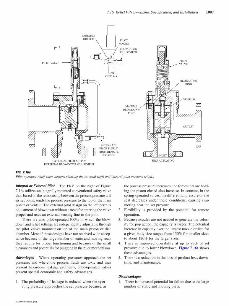
Integral or External Pilot The PRV on the right of Figure7.16s utilizes an integrally mounted conventional safety valvethat, based on the relationship between the process pressure andits set point, sends the process pressure to the top of the mainpiston or vents it. The external pilot design on the left permitsadjustment of blowdown without a need for entering the valveproper and uses an external sensing line to the pilot.
There are also pilot-operated PRVs in which the blow-down and relief settings are independently adjustable throughthe pilot valves mounted on top of the main piston or discchamber. Most of these designs have not received wide accep-tance because of the large number of static and moving sealsthey require for proper functioning and because of the smallclearances and potentials for plugging in the pilot mechanisms.
Advantages Where operating pressures approach the setpressure, and where the process fluids are toxic and thuspresent hazardous leakage problems, pilot-operated valvespresent special economic and safety advantages.
1. The probability of leakage is reduced when the oper-ating pressure approaches the set pressure because, as
the process pressure increases, the forces that are hold-ing the piston closed also increase. In contrast, in thespring-operated valves, the differential pressure on theseat decreases under these conditions, causing sim-mering near the set pressure.
2. Flexibility is provided by the potential for remoteoperation.
3. Because nozzles are not needed to generate the veloc-ity for pop action, the capacity is larger. The potentialincrease in capacity over the largest nozzle orifice fora given body size ranges from 150% for smaller sizesto about 120% for the larger sizes.
4. There is improved operability at up to 98% of setpressure due to lower blowdown. Figure 7.16t showsthese advantages.
5. There is a reduction in the loss of product loss, down-time, and maintenance.
Disadvantages1. There is increased potential for failure due to the large
number of static and moving parts.
FIG. 7.16sPilot-operated relief valve designs showing the external (left) and integral pilot versions (right).
A
PILOT VALVE
A
EXTERNAL PILOT SUPPLYEXTERNAL BLOWDOWN ADJUSTMENT
ALTERNATEPILOT SUPPLY
FROM REMOTELOCATION
MANUALBLOWDOWN
PORT
OUTLET
INLET
SELF ACTUATING
VENTURI
BLOWDOWNRING
PILOTVALVE
VARIABLEORIFICE
VIEW A-A
BLOW DOWNADJUSTMENT
PILOTNOZZLE
© 2003 by Béla Lipták
1008 Safety and Miscellaneous Sensors
2. Small clearances exist in pilot mechanisms that canbe plugged by dirty process fluids.
3. The lead lines between the process and the pilot valveand between pilot and main valve are small in size andtherefore have a higher potential for plugging.
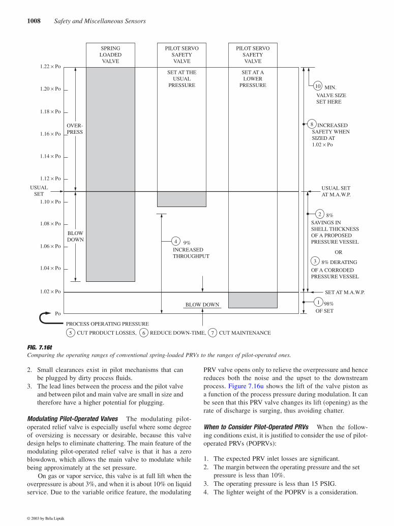
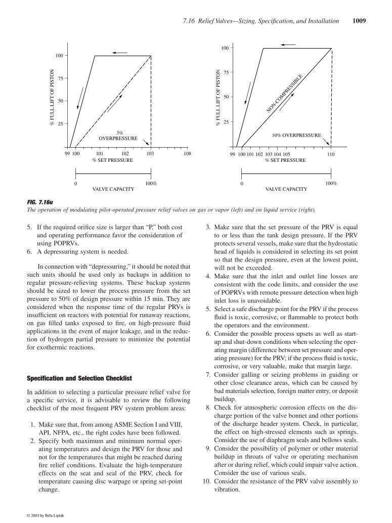
Modulating Pilot-Operated Valves The modulating pilot-operated relief valve is especially useful where some degreeof oversizing is necessary or desirable, because this valvedesign helps to eliminate chattering. The main feature of themodulating pilot-operated relief valve is that it has a zeroblowdown, which allows the main valve to modulate whilebeing approximately at the set pressure.
On gas or vapor service, this valve is at full lift when theoverpressure is about 3%, and when it is about 10% on liquidservice. Due to the variable orifice feature, the modulating
PRV valve opens only to relieve the overpressure and hencereduces both the noise and the upset to the downstreamprocess. Figure 7.16u shows the lift of the valve piston asa function of the process pressure during modulation. It canbe seen that this PRV valve changes its lift (opening) as therate of discharge is surging, thus avoiding chatter.
When to Consider Pilot-Operated PRVs When the follow-ing conditions exist, it is justified to consider the use of pilot-operated PRVs (POPRVs):
1. The expected PRV inlet losses are significant.2. The margin between the operating pressure and the set
pressure is less than 10%.3. The operating pressure is less than 15 PSIG.4. The lighter weight of the POPRV is a consideration.
FIG. 7.16tComparing the operating ranges of conventional spring-loaded PRVs to the ranges of pilot-operated ones.
USUAL SETAT M.A.W.P.
SAVINGS INSHELL THICKNESSOF A PROPOSEDPRESSURE VESSEL
SET AT M.A.W.P.
98%
PROCESS OPERATING PRESSURE
BLOW DOWN
INCREASEDTHROUGHPUT
INCREASEDSAFETY WHENSIZED AT1.02 × Po
VALVE SIZESET HERE
PILOT SERVOSAFETYVALVE
PILOT SERVOSAFETYVALVE
SET AT THEUSUAL
PRESSURE
OVER-PRESS
BLOWDOWN
1.22 × Po
1.20 × Po
1.18 × Po
1.16 × Po
1.14 × Po
1.12 × Po
1.10 × Po
1.08 × Po
1.06 × Po
1.04 × Po
1.02 × Po
SET AT ALOWER
PRESSURE
SPRINGLOADEDVALVE
USUALSET
Po
CUT PRODUCT LOSSES, REDUCE DOWN-TIME, CUT MAINTENANCE
10
8
2
3
1
765
4 9%
MIN.
8%
8% DERATING
OR
OF A CORRODEDPRESSURE VESSEL
OF SET
© 2003 by Béla Lipták
7.16 Relief Valves—Sizing, Specification, and Installation 1009
5. If the required orifice size is larger than “P,” both costand operating performance favor the consideration ofusing POPRVs.
6. A depressuring system is needed.
In connection with “depressuring,” it should be noted thatsuch units should be used only as backups in addition toregular pressure-relieving systems. These backup systemsshould be sized to lower the process pressure from the setpressure to 50% of design pressure within 15 min. They areconsidered when the response time of the regular PRVs isinsufficient on reactors with potential for runaway reactions,on gas filled tanks exposed to fire, on high-pressure fluidapplications in the event of major leakage, and in the reduc-tion of hydrogen partial pressure to minimize the potentialfor exothermic reactions.
Specification and Selection Checklist
In addition to selecting a particular pressure relief valve fora specific service, it is advisable to review the followingchecklist of the most frequent PRV system problem areas:
1. Make sure that, from among ASME Section I and VIII,API, NFPA, etc., the right codes have been followed.
2. Specify both maximum and minimum normal oper-ating temperatures and design the PRV for those andnot for the temperatures that might be reached duringfire relief conditions. Evaluate the high-temperatureeffects on the seat and seal of the PRV, check fortemperature causing disc warpage or spring set-pointchange.
3. Make sure that the set pressure of the PRV is equalto or less than the tank design pressure. If the PRVprotects several vessels, make sure that the hydrostatichead of liquids is considered in selecting its set pointso that the design pressure, even at the lowest point,will not be exceeded.
4. Make sure that the inlet and outlet line losses areconsistent with the code limits, and consider the useof POPRVs with remote pressure detection when highinlet loss is unavoidable.
5. Select a safe discharge point for the PRV if the processfluid is toxic, corrosive, or flammable to protect boththe operators and the environment.
6. Consider the possible process upsets as well as start-up and shut-down conditions when selecting the oper-ating margin (difference between set pressure and oper-ating pressure) for the PRV; if the process fluid is toxic,corrosive, or very valuable, make that margin large.
7. Consider galling or seizing problems in guiding orother close clearance areas, which can be caused bybad materials selection, foreign matter entry, or depositbuildup.
8. Check for atmospheric corrosion effects on the dis-charge portion of the valve bonnet and other portionsof the discharge header system. Check, in particular,the effect on high-stressed elements such as springs.Consider the use of diaphragm seals and bellows seals.
9. Consider the possibility of polymer or other materialbuildup in throats of valve or operating mechanismafter or during relief, which could impair valve action.Consider the use of various seals.
10. Consider the resistance of the PRV valve assembly tovibration.
FIG. 7.16uThe operation of modulating pilot-operated pressure relief valves on gas or vapor (left) and on liquid service (right).
100
75
50
25
99 100 101 102 103 108
VALVE CAPACITY VALVE CAPACITY
% SET PRESSURE % SET PRESSURE
% F
UL
L L
IFT
OF
PIST
ON
% F
UL
L L
IFT
OF
PIST
ON
100
75
50
25
99 100 101 102 103 104 105 110
3%OVERPRESSURE
10% OVERPRESSURE
0 100% 0 100%
NON-COM
PRESSIBLE
© 2003 by Béla Lipták
1010 Safety and Miscellaneous Sensors
11. Provide the valve designs that will minimize chatteron pulsating services.
12. Consider the probable condition of the valve and itsseating after exposure to external fire.
13. Evaluate whether the inlet, outlet, and/or the PRVitself requires thermal tracing, because winter tem-peratures can cause freezing of the process fluid. Eval-uate the need for steam jacketing to preventtendencies of solidification or crystallization withinthe valve. Check, in particular, the degree of steamjacketing required.
14. Make sure the features are provided to accuratelyguide the disc.
15. Check the need for valve position indicating devices.16. Check the availability and desirability of augmenting
normal disc seating forces or keeping them constantuntil the valve set point is reached so as to minimizeleakage.
17. Select seat and seal materials that are compatible with,and are not dissolved by, the process fluids. On H2Sservice, make sure that the valve materials are selectedin compliance with NACE MR0175. Also, make surethat the seat will reseat tightly after relieving on spe-cific service.
18. Make sure that the proper design features are selectedfor countering the effects of all types of backpressuresand the resulting variations in set point and blowdown.
19. Evaluate the consequences of, and provide the abilityto detect, bellows rupture.
20. Consider open-spring vs. bonneted-spring designs.21. Evaluate the degree of blowdown needed and answer
questions such as: Does blowdown have to be adjust-able? Can pop action be destroyed in adjusting blow-down?
22. Evaluate the need for special service valves such aschlorine service, toxic material, LPG storage tank,ICC approved, Coast Guard approved, etc.
23. Evaluate the need for various auxiliary features suchas test gags, lifting levers open or packed, screwedvs. bolted adjusting nut caps, etc.
24. Evaluate the level of noise produced and its effect ondischarge piping.
PRV OPERATION AND PERFORMANCE
The topics of blowdown, PRV chatter, valve tightness orleakage, and discharge system considerations are discussedin the following paragraphs.
Blowdown
The phenomenon of blowdown is caused by the use of springsin PRVs. The relieving system, when in operation, is a kineticsystem in which the PRV is at a point of high kinetic energyin contrast to the equipment that it is protecting. The valve
spring balances against a pressure that equals the pressure inthe protected tank minus the kinetic effects.
When the PRV is closed, the system is a static one, withno kinetic effects. Therefore, the pressure at the point ofspring balance is equal to that in the protected tank. Whenthe PRV is open, its inlet pressure is less than the pressurein the protected vessel because of the inlet pressure drop.This discrepancy between relieving and static conditionsrequires the allowance for blowdown.
Blowdown is the amount by which the protected tank’spressure has to drop below the PRV’s set pressure for the valveto reseat. This pressure difference is needed to ensure thatthe valve satisfies its force balance once it closes. The normalblowdown of a PRV is between 2 and 7% of set pressure.Pilot-operated PRVs can reduce the blowdown to about 2%,and engineers should always consult the supplier of a partic-ular PRV design for the actual percentage of their design.
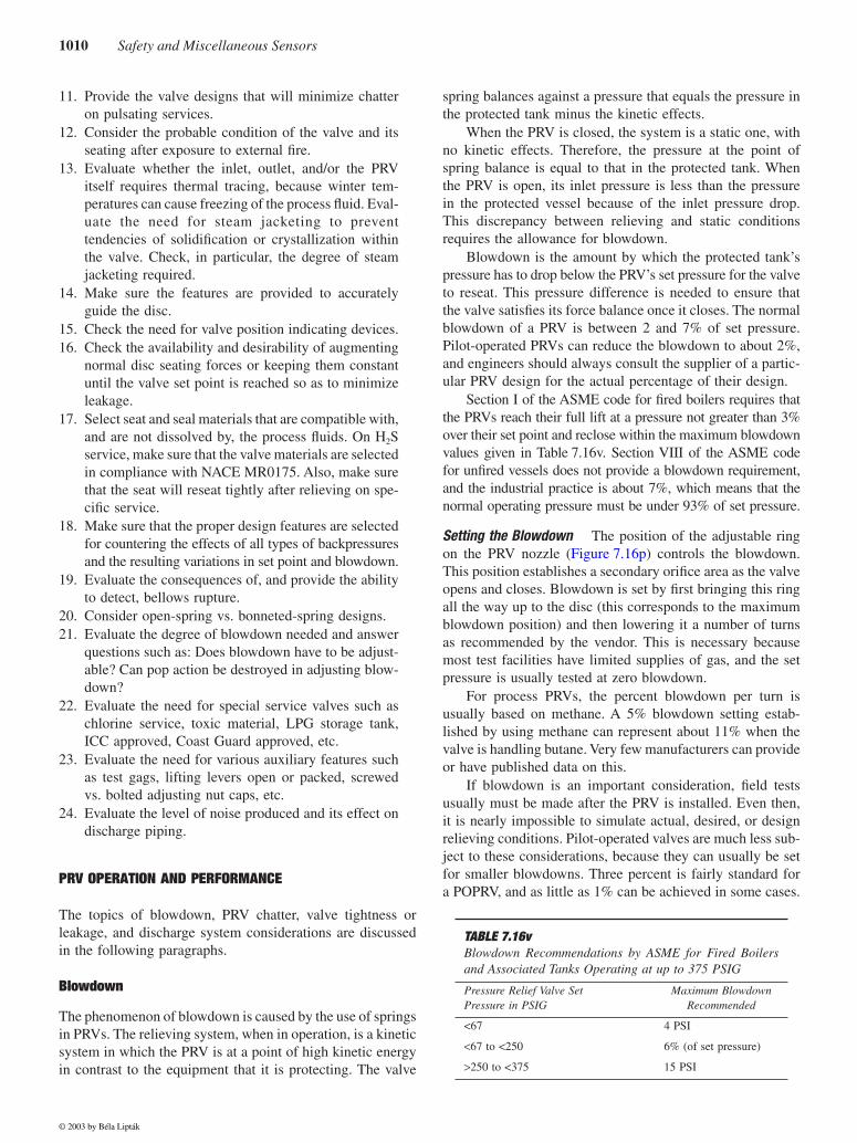
Section I of the ASME code for fired boilers requires thatthe PRVs reach their full lift at a pressure not greater than 3%over their set point and reclose within the maximum blowdownvalues given in Table 7.16v. Section VIII of the ASME codefor unfired vessels does not provide a blowdown requirement,and the industrial practice is about 7%, which means that thenormal operating pressure must be under 93% of set pressure.
Setting the Blowdown The position of the adjustable ringon the PRV nozzle (Figure 7.16p) controls the blowdown.This position establishes a secondary orifice area as the valveopens and closes. Blowdown is set by first bringing this ringall the way up to the disc (this corresponds to the maximumblowdown position) and then lowering it a number of turnsas recommended by the vendor. This is necessary becausemost test facilities have limited supplies of gas, and the setpressure is usually tested at zero blowdown.
For process PRVs, the percent blowdown per turn isusually based on methane. A 5% blowdown setting estab-lished by using methane can represent about 11% when thevalve is handling butane. Very few manufacturers can provideor have published data on this.
If blowdown is an important consideration, field testsusually must be made after the PRV is installed. Even then,it is nearly impossible to simulate actual, desired, or designrelieving conditions. Pilot-operated valves are much less sub-ject to these considerations, because they can usually be setfor smaller blowdowns. Three percent is fairly standard fora POPRV, and as little as 1% can be achieved in some cases.
TABLE 7.16vBlowdown Recommendations by ASME for Fired Boilersand Associated Tanks Operating at up to 375 PSIG
Pressure Relief Valve Set Pressure in PSIG
Maximum BlowdownRecommended
<67 4 PSI
<67 to <250 6% (of set pressure)
>250 to <375 15 PSI
© 2003 by Béla Lipták
7.16 Relief Valves—Sizing, Specification, and Installation 1011
PRV Chatter
Energy losses in the inlet piping to the PRV and the protectedtank (as well as an oversized valve) can lead to a conditionknown as chatter. Under these conditions, the PRV valverepeatedly cycles between its open and closed positions. Vari-ations in backpressure exceeding about 10% while a conven-tional PRV is relieving will also produce an unstable forcebalance condition and chatter.
Section II of API RP-520 endorses the widely used limitof 3% of set pressure as the maximum limit for the pressureloss in the inlet piping of a PRV. If, during relief, there arelosses much higher than 3%, they can drop the pressure atthe PRV seat to the reseating value. When this happens, thevalve closes, but as soon as it does, it is immediately sub-jected to a pressure rise, because closure has eliminated thekinetic effects. This rise in pressure can be enough to causethe PRV to reopen, and the cycle repeats.
Oversized valves can also cause this same condition,because a spring-loaded valve needs to have about 20 to 30%of its maximum flow to establish a stable force relationshipto maintain a stable disc position. Chatter has at least twodetrimental effects. One is that the valve’s seating conditionwill cause leakage. The other detrimental effect is that bel-lows failure can be expected if the disc chatters or flutters.
Chatter and Inlet Line Loss in POPRVs Pilot-operated valvesare not subject to chatter to the same extent, because they areopen or closed and cannot “throttle down” to flows in the 20to 30% range. Thus, if they are oversized, repeated openingsand closings may be needed to hold the system pressure, andthe net result is an action approaching chatter. Modulating pilot-operated relief valves overcome the basic problem of over-sizing and inlet pressure losses that are the causes of chatter.
As far as their set pressure is concerned, POPRVs canhave more than 3% pressure drop in their inlet line if theyare using a remote sensor (Figure 7.16s shows a local pres-sure pilot line). In such situations, the inlet line loss will stilllimit the relieving capacity of the valve. Therefore, the inletline loss should always be considered before the POPRV issized. If this is not done, when the inlet loss is calculated, itmight be found that a larger valve needs to be used. Naturally,in all high line loss cases, one should consider the relocation
of the POPRV to the point where the remote pilot line detectsthe process pressure.
Chatter on Liquid Service The subject of chatter is of spe-cial interest when relief valves are mounted on vessels thatare full of liquid. In the past, conventional valves designedfor vapor service were also used in liquid service, and thishad catastrophic results. This is because, in a liquid system,the pressure profile immediately upstream of the PRV valvecan change rapidly when the valve “pops open,” especiallyif there is a significant length of inlet piping between the valveand the vessel being protected. In that case, when the valveopens rapidly, an immediate reduction in pressure (at the inletto the valve) can make the PRV valve close prematurely. Thepressure then builds back up again quickly, the valve mustopen again, and the cycle repeats; thus, chatter ensues.
Most manufacturers offer a liquid-service trim designedspecifically to overcome this problem. The piping betweenthe inlet to the valve and the process being protected shouldbe kept to a minimum. Direct connection of the valve to theprocess vessels is preferred, if practical. Another potentialsolution is to use a pilot-operated or modulating pilot-operatedPRV valve that is provided with a remote sense line, depend-ing on the process conditions and type of process liquid.
PRV Tightness and Leakage
If fire is the only potential cause of overpressure, the valvetightness in spring-loaded valves can be markedly improvedby taking advantage of the 20% accumulated pressure thatthe ASME Code allows for this condition (Table 7.16w).
If one valve is set for 109% of maximum allowableworking pressure (MAWP), and 10% accumulation isallowed, this results in the same size valve as one set at 100%allowing 20% accumulation. However, if the operating pres-sure is at or near 90% of the maximum allowable, the firstvalve will have about twice the force keeping the seat tightat the operating pressure as that available in the case of thesecond valve (Figure 7.16x).
Using Two PRVs Another way to reduce leakage in someinstallations is to use two PRVs. This is a possibility if, in aparticular application, there is a large fire load but relatively
TABLE 7.16wASME Section VIII Provides the Following Recommendations for Maximum Set Pressures and Maximum Accu-mulated Pressures for Both Single and Multiple PRV Installations for Both Fire and Non-Fire Cases
PRV Installation Maximum Pressure
SingleSet%
SingleAccumulated%
MultipleSet%
MultipleAccumulated%
Non-Fire Case, 1st PRV 100% 110% 100% 116%
Non-Fire Case, Additional PRV N/A N/A 105% 116%
Fire Case, 1st PRV 100% 121% 100% 121%
Fire Case, Additional PRV N/A N/A 105% 121%
Fire Case, Supplemental PRV N/A N/A 110% 121%
© 2003 by Béla Lipták
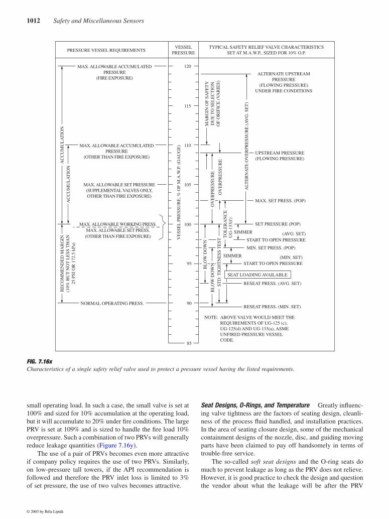
1012 Safety and Miscellaneous Sensors
small operating load. In such a case, the small valve is set at100% and sized for 10% accumulation at the operating load,but it will accumulate to 20% under fire conditions. The largePRV is set at 109% and is sized to handle the fire load 10%overpressure. Such a combination of two PRVs will generallyreduce leakage quantities (Figure 7.16y).
The use of a pair of PRVs becomes even more attractiveif company policy requires the use of two PRVs. Similarly,on low-pressure tall towers, if the API recommendation isfollowed and therefore the PRV inlet loss is limited to 3%of set pressure, the use of two valves becomes attractive.
Seat Designs, O-Rings, and Temperature Greatly influenc-ing valve tightness are the factors of seating design, cleanli-ness of the process fluid handled, and installation practices.In the area of seating closure design, some of the mechanicalcontainment designs of the nozzle, disc, and guiding movingparts have been claimed to pay off handsomely in terms oftrouble-free service.
The so-called soft seat designs and the O-ring seats domuch to prevent leakage as long as the PRV does not relieve.However, it is good practice to check the design and questionthe vendor about what the leakage will be after the PRV
FIG. 7.16xCharacteristics of a single safety relief valve used to protect a pressure vessel having the listed requirements.
PRESSURE VESSEL REQUIREMENTSVESSEL
PRESSURE
120
115
110
105
100
95
90
85
TYPICAL SAFETY RELIEF VALVE CHARACTERISTICSSET AT M.A.W.P., SIZED FOR 10% O.P.
ALTERNATE UPSTREAMPRESSURE
(FLOWING PRESSURE)UNDER FIRE CONDITIONS
ALT
ER
NA
TE
OV
ER
PRE
SSU
RE
(A
VG
. SE
T)
OV
ER
PRE
SSU
RE
VE
SSE
L P
RE
SSU
RE
, % O
F M
.A.W
.P. (
GA
UG
E)
BL
OW
DO
WN
RE
CO
MM
EN
DE
D M
AR
GIN
(10%
BU
T N
OT
LE
SS T
HA
N25
PSI
OR
172
.5 k
Pa)
AC
CU
MU
LA
TIO
NA
CC
UM
UL
AT
ION
BL
OW
DO
WN
STD
. TIG
HT
NE
SS T
EST
OV
ER
PRE
SSU
RE
MA
RG
IN O
F SA
FET
YD
UE
TO
SE
LE
CT
ION
OF
OR
IFIC
E (
VA
RIE
S)
UPSTREAM PRESSURE(FLOWING PRESSURE)
MAX. SET PRESS. (POP)
SET PRESSURE (POP)
START TO OPEN PRESSURE
MIN. SET PRESS. (POP)
START TO OPEN PRESSURE
RESEAT PRESS. (AVG. SET)
RESEAT PRESS. (MIN. SET)NORMAL OPERATING PRESS.
MAX. ALLOWABLE WORKING PRESS.MAX. ALLOWABLE SET PRESS.(OTHER THAN FIRE EXPOSURE)
MAX. ALLOWABLE SET PRESSURE(SUPPLEMENTAL VALVES ONLY,OTHER THAN FIRE EXPOSURE)
MAX. ALLOWABLE ACCUMULATEDPRESSURE
(OTHER THAN FIRE EXPOSURE)
MAX. ALLOWABLE ACCUMULATEDPRESSURE
(FIRE EXPOSURE)
NOTE: ABOVE VALVE WOULD MEET THEREQUIREMENTS OF UG-125 (c),UG-125(d) AND UG-133(a), ASMEUNFIRED PRESSURE VESSELCODE.
SEAT LOADING AVAILABLE
(AVG. SET)
(MIN. SET)
SIMMER
TO
LE
RA
NC
EU
G-1
33(f
)
SIMMER
© 2003 by Béla Lipták
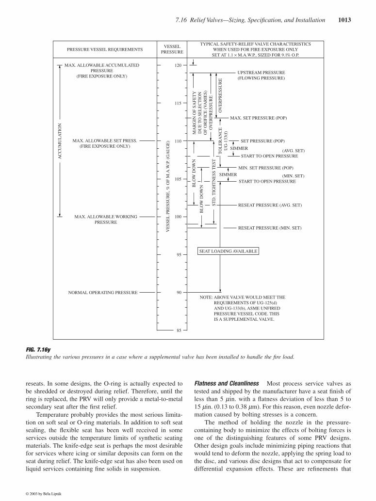
7.16 Relief Valves—Sizing, Specification, and Installation 1013
reseats. In some designs, the O-ring is actually expected tobe shredded or destroyed during relief. Therefore, until thering is replaced, the PRV will only provide a metal-to-metalsecondary seat after the first relief.
Temperature probably provides the most serious limita-tion on soft seal or O-ring materials. In addition to soft seatsealing, the flexible seat has been well received in someservices outside the temperature limits of synthetic seatingmaterials. The knife-edge seat is perhaps the most desirablefor services where icing or similar deposits can form on theseat during relief. The knife-edge seat has also been used onliquid services containing fine solids in suspension.
Flatness and Cleanliness Most process service valves astested and shipped by the manufacturer have a seat finish ofless than 5 µin. with a flatness deviation of less than 5 to15 µin. (0.13 to 0.38 µm). For this reason, even nozzle defor-mation caused by bolting stresses is a concern.
The method of holding the nozzle in the pressure-containing body to minimize the effects of bolting forces isone of the distinguishing features of some PRV designs.Other design goals include minimizing piping reactions thatwould tend to deform the nozzle, applying the spring load tothe disc, and various disc designs that act to compensate fordifferential expansion effects. These are refinements that
FIG. 7.16yIllustrating the various pressures in a case where a supplemental valve has been installed to handle the fire load.
AC
CU
MU
LA
TIO
N
TYPICAL SAFETY-RELIEF VALVE CHARACTERISTICSWHEN USED FOR FIRE EXPOSURE ONLYSET AT 1.1 × M.A.W.P., SIZED FOR 9.1% O.P.
UPSTREAM PRESSURE(FLOWING PRESSURE)
MA
RG
IN O
F SA
FET
YD
UE
TO
SE
LE
CT
ION
OF
OR
IFIC
E (
VA
RIE
S)O
VE
RPR
ESS
UR
E
OV
ER
PRE
SSU
RE
MAX. SET PRESSURE (POP)
TO
LE
RA
NC
EU
G-1
33(f
)
SIMMER
SIMMER
SET PRESSURE (POP)
MIN. SET PRESSURE (POP)
BL
OW
DO
WN
BL
OW
DO
WN
STD
. TIG
HT
NE
SS T
EST
(AVG. SET)
(MIN. SET)START TO OPEN PRESSURE
START TO OPEN PRESSURE
RESEAT PRESSURE (AVG. SET)
RESEAT PRESSURE (MIN. SET)
NORMAL OPERATING PRESSURE
MAX. ALLOWABLE WORKINGPRESSURE
MAX. ALLOWABLE SET PRESS.(FIRE EXPOSURE ONLY)
MAX. ALLOWABLE ACCUMULATEDPRESSURE
(FIRE EXPOSURE ONLY)
PRESSURE VESSEL REQUIREMENTS
120
115
110
105
100
95
90
85
SEAT LOADING AVAILABLE
NOTE: ABOVE VALVE WOULD MEET THEREQUIREMENTS OF UG-125(d)AND UG-133(b), ASME UNFIREDPRESSURE VESSEL CODE. THISIS A SUPPLEMENTAL VALVE.
VE
SSE
L P
RE
SSU
RE
, % O
F M
.A.W
.P. (
GA
UG
E)
VESSELPRESSURE
© 2003 by Béla Lipták
1014 Safety and Miscellaneous Sensors
manufacturers have developed as users demanded tighter,longer-lasting valves while the PRV service conditions grewprogressively more severe.
The influence of fluid cleanliness on PRV performanceis illustrated by contrasting the refinery or chemical industrypractices to those of missile service. In a number of refineryand chemical plant applications, experience has shown thatthe valve will leak once it has opened and reseated. In manyplants, it is accepted that you may just as well take it down,clean and lap it, reset it, and reinstall it.
Contrast this with the shop inspection requirements onsome missile service PRVs where 200 successive cyclingson clean, high-pressure nitrogen must still leave the valvevirtually bubble tight. This requirement is regularly met ona production basis.
PRV INSTALLATION
The inlet and outlet line losses of the individual PRVs arecalculated on the basis of their rated capacity, not on theirrequired relieving capacity. This approach should also beused as the basis for sizing PRV manifolds so as to minimizebuilt-up backpressure and PRV chattering.
PRV Location
Pressure relief valves should be placed close to the tank orequipment they are protecting to minimize their inlet pressurelosses. Their location should also be selected with the goalof avoiding unstable flow patterns and minimizing inlet tur-bulence. Therefore, a minimum distance of ten pipe diametersshould be provided between such fittings as orifices, elbows,valves, and flow nozzles and the PRV.
Relief valves should be located with full considerationgiven to the need for convenient maintenance access. Easyand safe access is a very important element in making surethat inspection and testing is regularly performed. If there isno convenient natural access to the valve, the installation ofa platform should be considered. PRVs should not be locatedat the end of long and stagnant horizontal pipes.
PRV Mounting
Vapor relief valves should be mounted on the top of theprotected tank and should be connected to its vapor spaceabove the liquid level or to piping that is connected to thevapor space. Liquid service PRVs should be connected belowthe normal liquid level in the tank. All PRVs should alwaysbe mounted vertically, not only because horizontal mountingcan adversely affect their operation but also because horizon-tal mounting violates the ASME code and the API recom-mended practice.
Pressure relief valves should not be mounted close tovibration or turbulence sources such as orifice plates or positive
displacement pumps/compressors. This is because the pres-sure spikes can cause premature relieving, and the pulsationcan alter the PRV’s set pressure.
PRVs should not be mounted at the end of horizontalpipes, either. This is because, when the PRV opens, debrissuch as welding slag, pipe scale, and foreign objects that arepresent in the horizontal pipe will be transported into thevalve and will either cause leaking after the PRV recloses orrequire immediate maintenance to be performed on the valve.
PRV Inlet Piping
The inlet pipe to all PRVs should be as short and direct aspossible and should be the same size or larger than the inletconnection of the valve. The inlet pipe should not connect tolocations in the process where unstable or turbulent flowpatterns exist. When the PRV is relieving vapors, it shouldbe sloped upward to the PRV so that liquid entrainment wouldbe minimal. If the line has a low point, it should be drained.
If the process is such that the inlet pipe can be plugged,it is recommended to provide a clean, nonreactive liquidpurge to keep the inlet line clean. If plugging of the inlet linecan be caused by low temperatures, such as generated by thecooling of high-viscosity polymers or by ice formation atambient temperatures, the PRV inlet line should be heattraced.
PRV Outlet Piping
The outlet pipe size should be the same as or larger than thePRV outlet connection. The outlet pipe should be sized tolimit the backpressure when the PRV is relieving so that thisbackpressure will neither shift the set pressure nor preventthe PRV from operating at its full rated capacity. In case ofconventional spring-loaded PRVs, the maximum limit forbuilt-up backpressure is 10% of the set pressure. For PRVswith balanced bellows, it is between 30 and 50%. For pilot-operated PRVs, it is 50% of the set pressure.
The outlet pipe should always be properly drained. Thepreferred choice is to provide self-draining. When that is notpossible, a low-point drain with shut-off valve should beprovided, and the drain should be piped to a closed system.
In selecting the materials of construction for the outletpipe, design engineers should evaluate the possibility ofautorefrigeration occurring during PRV relieving. If that isthe case, the expected low temperatures should be calculated,and suitable pipe materials should be selected to protectagainst fracturing the brittle metal.
When the PRV discharges to the atmosphere, long-radiuselbows should be used, and both the weight of the outlet pipeand the reaction forces should both be considered in design-ing the pipe supports. The tail pipes should be angle-cut toreduce both the relieving noise level and the reaction force.Local bylaws should be consulted in setting the allowablenoise level, which should be calculated on the basis of APIRP 521, Section 5.4.4.3.4, in the 1997 edition.
© 2003 by Béla Lipták
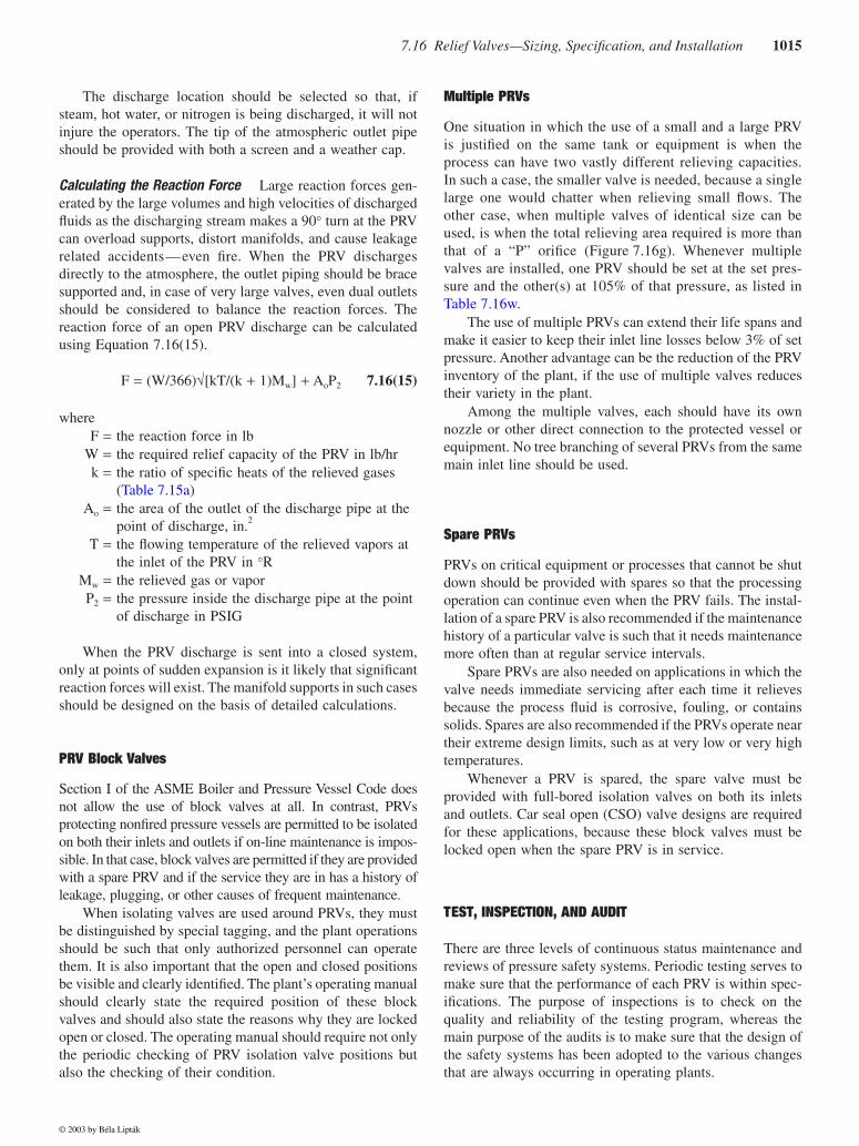
7.16 Relief Valves—Sizing, Specification, and Installation 1015
The discharge location should be selected so that, ifsteam, hot water, or nitrogen is being discharged, it will notinjure the operators. The tip of the atmospheric outlet pipeshould be provided with both a screen and a weather cap.
Calculating the Reaction Force Large reaction forces gen-erated by the large volumes and high velocities of dischargedfluids as the discharging stream makes a 90° turn at the PRVcan overload supports, distort manifolds, and cause leakagerelated accidents—even fire. When the PRV dischargesdirectly to the atmosphere, the outlet piping should be bracesupported and, in case of very large valves, even dual outletsshould be considered to balance the reaction forces. Thereaction force of an open PRV discharge can be calculatedusing Equation 7.16(15).
F = (W/366)√[kT/(k + 1)Mw] + AoP2 7.16(15)
whereF = the reaction force in lb
W = the required relief capacity of the PRV in lb/hrk = the ratio of specific heats of the relieved gases
(Table 7.15a)Ao = the area of the outlet of the discharge pipe at the
point of discharge, in.2
T = the flowing temperature of the relieved vapors at the inlet of the PRV in °R
Mw = the relieved gas or vaporP2 = the pressure inside the discharge pipe at the point
of discharge in PSIG
When the PRV discharge is sent into a closed system,only at points of sudden expansion is it likely that significantreaction forces will exist. The manifold supports in such casesshould be designed on the basis of detailed calculations.
PRV Block Valves
Section I of the ASME Boiler and Pressure Vessel Code doesnot allow the use of block valves at all. In contrast, PRVsprotecting nonfired pressure vessels are permitted to be isolatedon both their inlets and outlets if on-line maintenance is impos-sible. In that case, block valves are permitted if they are providedwith a spare PRV and if the service they are in has a history ofleakage, plugging, or other causes of frequent maintenance.
When isolating valves are used around PRVs, they mustbe distinguished by special tagging, and the plant operationsshould be such that only authorized personnel can operatethem. It is also important that the open and closed positionsbe visible and clearly identified. The plant’s operating manualshould clearly state the required position of these blockvalves and should also state the reasons why they are lockedopen or closed. The operating manual should require not onlythe periodic checking of PRV isolation valve positions butalso the checking of their condition.
Multiple PRVs
One situation in which the use of a small and a large PRVis justified on the same tank or equipment is when theprocess can have two vastly different relieving capacities.In such a case, the smaller valve is needed, because a singlelarge one would chatter when relieving small flows. Theother case, when multiple valves of identical size can beused, is when the total relieving area required is more thanthat of a “P” orifice (Figure 7.16g). Whenever multiplevalves are installed, one PRV should be set at the set pres-sure and the other(s) at 105% of that pressure, as listed inTable 7.16w.
The use of multiple PRVs can extend their life spans andmake it easier to keep their inlet line losses below 3% of setpressure. Another advantage can be the reduction of the PRVinventory of the plant, if the use of multiple valves reducestheir variety in the plant.
Among the multiple valves, each should have its ownnozzle or other direct connection to the protected vessel orequipment. No tree branching of several PRVs from the samemain inlet line should be used.
Spare PRVs
PRVs on critical equipment or processes that cannot be shutdown should be provided with spares so that the processingoperation can continue even when the PRV fails. The instal-lation of a spare PRV is also recommended if the maintenancehistory of a particular valve is such that it needs maintenancemore often than at regular service intervals.
Spare PRVs are also needed on applications in which thevalve needs immediate servicing after each time it relievesbecause the process fluid is corrosive, fouling, or containssolids. Spares are also recommended if the PRVs operate neartheir extreme design limits, such as at very low or very hightemperatures.
Whenever a PRV is spared, the spare valve must beprovided with full-bored isolation valves on both its inletsand outlets. Car seal open (CSO) valve designs are requiredfor these applications, because these block valves must belocked open when the spare PRV is in service.
TEST, INSPECTION, AND AUDIT
There are three levels of continuous status maintenance andreviews of pressure safety systems. Periodic testing serves tomake sure that the performance of each PRV is within spec-ifications. The purpose of inspections is to check on thequality and reliability of the testing program, whereas themain purpose of the audits is to make sure that the design ofthe safety systems has been adopted to the various changesthat are always occurring in operating plants.
© 2003 by Béla Lipták
1016 Safety and Miscellaneous Sensors
PRV Testing
All PRVs should be tested before their installation, after eachfire event or case of relieving dirty process fluids, and at thefrequency of the service intervals set by the plant. Certifiedtechnicians are required to perform the PRV tests. Testing isperformed either in a test workshop or, if the PRVs areprovided with field test connections, in situ.
During the test, technicians should look for signs of tam-pering, process-related damage, leakage, wear, and corrosion.They should also test the set pressure, blowdown, overpres-sure, and seat tightness of each PRV and make the requiredadjustment, if any. To test the tightness of the seat, theyshould follow API Standard 527.
After the testing is done, the staff should prepare a testreport for each PRV and mark the PRV tag with the date andtest pressure that was checked.
PRV Inspection
The purpose of the inspection is to ensure that the testingwas properly performed and that no foreign objects, weldingbeads, or rust was left inside the PRVs. The inspector willalso check for signs of tampering, leakage, erosion, wear,and corrosion and verify that the PRV flanges are clean andin good condition.
The inspectors will also make sure that the PRV’s tag isthe same one that appears on the P&ID flow sheet and thatit is securely tied to the valve. Finally, the inspectors shouldalso make sure that the performance data obtained duringtesting and reported in the test report are acceptable for theparticular PRV application.
PRV Audit
The audit evaluates the pressure safety of a complete pro-cessing unit.2 The main goal of the audit is to confirm thatthe tasks in the action list of the previous audit have beenperformed, and the maintenance strategy of the plant has beenproperly followed. Any process changes that have occurredsince the last audit are carefully evaluates in terms of theireffects on the pressure safety systems.
If, because of the process changes, PRVs can be removed,or previously acceptable ones have become oversized orundersized, the audit should reveal that. The final product ofan audit is a prioritized new action list that will serve tofurther improve the operating safety of the plant.
References
1. Farris Engineering, SizeMasterTM Mark IV, Pressure Relief Valve Engi-neering Software, Version 4.2 (http://www.avrasoft.com/sizemaster).
2. Wong, W. Y., Improve PRV audit, Hydrocarbon Process., November1998.
Bibliography
ANSI B31.1, Nonmandatory Rules for the Design of Safety Relief Installation,Power Piping, Appendix II.
API-RP-520 Parts I and II, Sizing, Selection, and Installation of Pressure-Relieving Systems in Refineries, American Petroleum Institute,Washington, D.C., 2000 and 1994, respectively.
API-RP-521, Guide for Pressure-Relieving and Depressuring Systems,American Petroleum Institute, Washington, D.C., 1990.
API Standard 526, Flanged Steel Safety Relief Valves, American PetroleumInstitute, Washington, D.C., 1984.
API Standard 527, Seat Tightness of Safety Relief Valves with Metal to MetalSeats” American Petroleum Institute, Washington, D.C., 1991.
API RP 576, Inspection of Pressure Relieving Devices, American PetroleumInstitute, Washington, D.C., 1984.
API RP 2000, Venting Atmospheric and Low-Pressure Storage Tanks, Amer-ican Petroleum Institute, Washington, D.C., 2000.
ASME Boiler and Pressure Vessel Code, Section I (Power Boilers), SectionIV (Low Pressure Heating Boilers), and Section VIII (Pressure Vessels,Division 1), American Society of Mechanical Engineers, New York.
Benedetti, R. P., NFPA 30: an update and a look into the future, ProcessSafety Prog., 17(1), Spring 1998.
Bernstein, M. D. and Bloomfield, W. J., Malfunctions of safety valves dueto flow induced vibrations, Proc.1989 ASME Pressure Vessel and Pip-ing Conference, PVP-154, 155–164.
Bilanin, A. J. and Teske, M. E., Modelling flow through spring loaded reliefvalves, Proc. 1990 ASME Pressure Vessel and Piping Conference,PVP-190, 29–36, 1990.
Brahmbhatt, S. R., Are liquid thermal relief valves needed, Chem. Eng.,International ed., 91(10), May 1984.
Burns, M. L., Jr., The practical application of flow test data for safety reliefvalves and rupture discs used in combination, Paper C380/84, I. Mech.E. Conference, 1984.
Chester, J. R., The best pressure relief valves: simple or intelligent, InTech,January 1985.
Coker, A. K., Program sizes compressible flow for discharge piping, Oil andGas J., 87(50), December 1989.
Constantinescu, S., Sizing gas pressure relief nozzles, Chem. Eng., Interna-tional ed., 92(9), April 1985.
Crozier, R. A., Jr., Sizing relief valves for fire emergencies, Chem. Eng.,International ed., 92(22), October 1985.
Ekmann, M. E., A thematic approach to system safety, Process Safety Prog.,17(3), Fall 1998.
Emerson, G. B., Pressure relief valves: some selection guidelines, InTech,33(2), February 1986.
Emerson, G. B., Pressure relief valve types and selection, HydrocarbonProcess., International ed., 67(5), May 1988.
Folcy, J. D., Tank vents offer safety protection in critical service, Chem.Process, 51(6), May 1988.
Frommann, O. and Friedel, L., Analysis of safety relief valve chatter inducedby pressure waves in gas flow, J. Loss Prev. Process Ind., 11(4), July1998.
Gano, J. C., Differential sensing direct control gas storage well safety valve,Society of Petroleum Engineers of AIME, Richardson, TX, 287–294,Proc. Conf. No. 12675, 287–294, 1989.
Garucci, V. A. and Mueller, R. T., Acoustically Induced Piping Vibrationsin High Capacity Pressure Reducing Systems, Exxon Research &Engineering Co., Florham Park, New Jersey, ASME Paper No. 82-WAS/PVP-8.
Going, W. S. and Pringle, R. E., Safety valve technology for the 1990’s,Society of Petroleum Engineers of AIME, Richardson, TX, Proc. Conf.No. 12667, 545–552, 1989.
Gruber, U., Puppich, P., Noll, E., and Mewes, D., Time dependent behaviorof the pressure in an explosion as a basis for the design of pressurevessels and apparatus, Int. Chem. Eng., 31(1), January 1991.
Hendershot, D. C., Inherently safer chemical process design, J. Loss Prev.Process Ind., 10(3), 1997.
© 2003 by Béla Lipták
7.16 Relief Valves—Sizing, Specification, and Installation 1017
Jones, B. G. and Duckett, R. C., Thermographic survey of the integrity ofa process plant pressure relief system, Plant Op. Prog., 4(3), 1985.
King, R., Safety in the Process Industries, Butterworth-Heinemann, London,1990.
Kletz, T., Learning from Disaster, Gulf Publishing, Houston, TX, 2001a.Kletz, T., Learning from Accidents, Gulf Publishing, Houston, TX, 2001b.Lai, Y. S., Design principles of safety valve on line testing device, ASME,
PWR 45, Proc. Conf. No. 13245, 6, 1989.Lai, Y. S., Conventional Spring Loaded Relief Valves Subjected to Back
Pressure, ASME Pressure Vessel and Piping Division, New York, PVP180, 1989.
Lees, F. P., Loss Prevention, Gulf Publishing, Houston, TX, 1996.Leismer, D. D., Redundant control subsurface safety systems, ASME Petro-
leum Division, New York, PD 29, Proc. Conf. No. 13045, 1990.Leung, J. C., The omega method for discharge rate evaluation, Proc. Int.
Symp. Runaway Reactions and Pressure Relief Design, 367, AmericanInstitute of Chemical Engineers, New York, 1995.
Morley, P. G., Sizing pressure relief valves for gas duty, Chem. Eng. J.(Rugby-GB), 463, August 1989.
Moss, D. R., Pressure Vessel Design Manual, Gulf Publishing, Houston,TX, 1987.
Muser, W. and Schauki, N., New Requirements for Safety and Relief Valves,ASME Pressure Vessel and Piping Division, PVP-180, 1989.
Newman, G., Careful consideration in selecting safety valves, Valves andActuators for the Process Ind., BVAMA 50th Anniv. Suppl., April1989.
Papa, D. M., How back pressure affects safety relief valves, HydrocarbonProcess., 62(5), May 1983.
Pavel, A. and Dascalu, C., Thermal design of industrial flares, part III, Chem.Eng., International ed., 30(3), July 1990.
Peicheng, H., Pusheng, Z., and Elkouh, A. F., Relief valve and safety mem-brane arrangement in lieu of surge tank, Energy Eng., 115(2), August1989.
Rodmill, F., Human Factors in Safety-Critical System, Gulf Publishing,Houston, TX, 1997.
Sallet, D. W. and Somers, G. W., Flow capacity and response of safety reliefvalves to saturated water flow, Plant Op. Prog., 4(4), October 1985.
Simiskey, P. L. and Faulkner, C. R., Better relief system design, HydrocarbonProc., 68(5), May 1989.
Simon, U., Rauffman, N., and Schafer, H., Testing of Safety Related Valvesof PWR and BWR Power Plants, ASME, Pressure Vessel and PipingDiv., P – VP-180, 1989.
Sumathipala, K., Venart, J. E. S., and Stewart, F. R., Two phase swellingand entrainment during pressure relief discharges, Haz. Mat. (Amster-dam), 25(1–2), October 1990.
Taylor, C., Designing for safer pressure relief, Process Eng. (UK), 70(12),December 1989.
Theisen, J. T., Chatter free relief valves, InTech, July 1986.Theisen, J. T., Calculating back pressure in relief valves and piping, InTech,
March 1988.Van Zijl, F. M. J., Indirect working safety valve, PT/Procestech (Netherlands),
38(11), November 1983.Watson, J., Stability of a two stage pressure relief valve, Proc. 1989
American Control Conf., 2, 1503–1507, 1989.Wong, W. Y., Safer Relief Valve Sizing, Chem. Eng., International ed., 96(5),
May 1989.Wong, W. Y., Protect plants against overpressure, Chem. Eng., June
2001.Wong, W. Y., Improve PRV audit, Hydrocarbon Process., November 1998.Woolfolk, W. and Sanders, R., Process Safety Relief Valve Testing, PPG
Industries, CEP, March 1984.
© 2003 by Béla Lipták