7044 44P Series Model 270 Service Manual
339
RS/6000 44P Series Model 270 Service Guide SA38-0572-01 IBM
-
Upload
warren-draper -
Category
Documents
-
view
158 -
download
5
description
service guide
Transcript of 7044 44P Series Model 270 Service Manual

RS/6000 44P Series Model 270
Service Guide
SA38-0572-01
IBM

Second Edition (October 2000)
Before using this information and the product it supports, read the information in “Safety Notices” on page vii,“Appendix A. Environmental Notices” on page 279, and “Appendix B. Notices” on page 281.
International Business Machines Corporation, 2000. All rights reserved. Note to U.S. Government UsersRestricted Rights--Use, duplication or disclosure restrictions by GSA ADP Schedule Contract with IBM Corp.

Contents
Safety Notices . . . . . . . . . . . . . . . . . . . . . . . . viiElectrical Safety . . . . . . . . . . . . . . . . . . . . . . . viiLaser Safety Information . . . . . . . . . . . . . . . . . . . . viii
Data Integrity and Verification . . . . . . . . . . . . . . . . . . xi
About This Book . . . . . . . . . . . . . . . . . . . . . . xiiiISO 9000 . . . . . . . . . . . . . . . . . . . . . . . . . xiiiOnline Publications . . . . . . . . . . . . . . . . . . . . . . xiiiRelated Publications . . . . . . . . . . . . . . . . . . . . . . xiiiTrademarks . . . . . . . . . . . . . . . . . . . . . . . . . xiv
Chapter 1. Reference Information . . . . . . . . . . . . . . . . . 1System Unit Locations. . . . . . . . . . . . . . . . . . . . . . 1System Cables . . . . . . . . . . . . . . . . . . . . . . . . 9Location Codes . . . . . . . . . . . . . . . . . . . . . . . . 9Specifications . . . . . . . . . . . . . . . . . . . . . . . . 17Power Cables . . . . . . . . . . . . . . . . . . . . . . . . 19Service Inspection Guide . . . . . . . . . . . . . . . . . . . . 20
Chapter 2. Diagnostics Overview . . . . . . . . . . . . . . . . . 21Maintenance Analysis Procedures (MAPs). . . . . . . . . . . . . . . 21Checkpoints . . . . . . . . . . . . . . . . . . . . . . . . . 22FRU Isolation . . . . . . . . . . . . . . . . . . . . . . . . 23Service Director for the RS/6000 . . . . . . . . . . . . . . . . . . 23Using the Service Processor and Service Director Features . . . . . . . . . 24
Chapter 3. Maintenance Analysis Procedures (MAPs) . . . . . . . . . . 27Quick Entry MAP . . . . . . . . . . . . . . . . . . . . . . . 27MAP 1020: Problem Determination . . . . . . . . . . . . . . . . . 34MAP 1240: Memory Problem Resolution . . . . . . . . . . . . . . . 39MAP 1520: Power . . . . . . . . . . . . . . . . . . . . . . . 45MAP 1540: Minimum Configuration . . . . . . . . . . . . . . . . . 50
Chapter 4. Checkpoints . . . . . . . . . . . . . . . . . . . . 71Service Processor Checkpoints . . . . . . . . . . . . . . . . . . 71Firmware Checkpoints . . . . . . . . . . . . . . . . . . . . . 75
Chapter 5. Error Code to FRU Index . . . . . . . . . . . . . . . . 93Considerations for Using this Chapter . . . . . . . . . . . . . . . . 93Firmware/POST Error Codes . . . . . . . . . . . . . . . . . . . 94Memory Problem Determination Bits . . . . . . . . . . . . . . . . 141Bus SRN to FRU Reference Table . . . . . . . . . . . . . . . . . 142Typical Boot Sequence. . . . . . . . . . . . . . . . . . . . . 143
Chapter 6. Loading the System Diagnostics . . . . . . . . . . . . . 145
iii

Performing Slow Boot . . . . . . . . . . . . . . . . . . . . . 145Standalone Diagnostics . . . . . . . . . . . . . . . . . . . . 145Online Diagnostics . . . . . . . . . . . . . . . . . . . . . . 145Default Boot List and Service Mode Boot List . . . . . . . . . . . . . 146
Chapter 7. Using the Service Processor . . . . . . . . . . . . . . 147Service Processor Menus . . . . . . . . . . . . . . . . . . . . 149General User Menu . . . . . . . . . . . . . . . . . . . . . . 150Privileged User Menus . . . . . . . . . . . . . . . . . . . . . 151Service Processor Functions . . . . . . . . . . . . . . . . . . . 171System Power-On Methods . . . . . . . . . . . . . . . . . . . 173Service Processor Call-In Security . . . . . . . . . . . . . . . . . 174Service Processor Reboot/Restart Recovery . . . . . . . . . . . . . 174Service Processor System Monitoring - Surveillance . . . . . . . . . . . 177Console Mirroring . . . . . . . . . . . . . . . . . . . . . . 179Service Processor Firmware Updates . . . . . . . . . . . . . . . . 179Service Processor Error Log . . . . . . . . . . . . . . . . . . . 180System POST Errors . . . . . . . . . . . . . . . . . . . . . 180Service Processor Operational Phases . . . . . . . . . . . . . . . 181Service Processor Procedures in Service Mode . . . . . . . . . . . . 183
Chapter 8. System Management Services . . . . . . . . . . . . . . 185Graphical System Management Services. . . . . . . . . . . . . . . 185Config . . . . . . . . . . . . . . . . . . . . . . . . . . 188Multiboot . . . . . . . . . . . . . . . . . . . . . . . . . 189Utilities . . . . . . . . . . . . . . . . . . . . . . . . . . 191Error Log . . . . . . . . . . . . . . . . . . . . . . . . . 198RIPL . . . . . . . . . . . . . . . . . . . . . . . . . . . 199SCSI ID. . . . . . . . . . . . . . . . . . . . . . . . . . 204Firmware Update. . . . . . . . . . . . . . . . . . . . . . . 205Text-Based System Management Services . . . . . . . . . . . . . . 207Display Configuration . . . . . . . . . . . . . . . . . . . . . 208Multiboot Menu . . . . . . . . . . . . . . . . . . . . . . . 208Utilities . . . . . . . . . . . . . . . . . . . . . . . . . . 212Select Language . . . . . . . . . . . . . . . . . . . . . . . 219Open Firmware . . . . . . . . . . . . . . . . . . . . . . . 220
Chapter 9. Removal and Replacement Procedures . . . . . . . . . . 221Handling Static-Sensitive Devices . . . . . . . . . . . . . . . . . 221Stopping the System Unit . . . . . . . . . . . . . . . . . . . . 222Procedure List . . . . . . . . . . . . . . . . . . . . . . . 222Covers . . . . . . . . . . . . . . . . . . . . . . . . . . 223Processor and Memory Card Cover . . . . . . . . . . . . . . . . 228Memory Cards . . . . . . . . . . . . . . . . . . . . . . . 229Memory Modules. . . . . . . . . . . . . . . . . . . . . . . 233Processor Card . . . . . . . . . . . . . . . . . . . . . . . 236Adapters . . . . . . . . . . . . . . . . . . . . . . . . . 239Internal Drives . . . . . . . . . . . . . . . . . . . . . . . 241Disk Drives . . . . . . . . . . . . . . . . . . . . . . . . 242Configuration or Unconfiguration of Disk Drives . . . . . . . . . . . . 244
iv RS/6000 44P Series Model 270 Service Guide

Battery Replacement . . . . . . . . . . . . . . . . . . . . . 245System Board. . . . . . . . . . . . . . . . . . . . . . . . 249I/O Board . . . . . . . . . . . . . . . . . . . . . . . . . 251Power Supply . . . . . . . . . . . . . . . . . . . . . . . . 254Operator Panel . . . . . . . . . . . . . . . . . . . . . . . 257Operator Panel Vital Product Data (VPD) Update Procedure . . . . . . . . 259CEC Fan . . . . . . . . . . . . . . . . . . . . . . . . . 261I/O Fan . . . . . . . . . . . . . . . . . . . . . . . . . . 262Disk Drive Cage . . . . . . . . . . . . . . . . . . . . . . . 263CD-ROM Drive, Tape Drive, Diskette Drive . . . . . . . . . . . . . . 265
Chapter 10. Parts Information . . . . . . . . . . . . . . . . . . 267Keyboards and Mouse . . . . . . . . . . . . . . . . . . . . . 272Keyboards and Mouse (Black) . . . . . . . . . . . . . . . . . . 274Power Cables. . . . . . . . . . . . . . . . . . . . . . . . 276
Appendix A. Environmental Notices . . . . . . . . . . . . . . . . 279Product Recycling and Disposal . . . . . . . . . . . . . . . . . . 279Environmental Design . . . . . . . . . . . . . . . . . . . . . 279Unit Emissions . . . . . . . . . . . . . . . . . . . . . . . 279
Appendix B. Notices . . . . . . . . . . . . . . . . . . . . . 281
Appendix C. Firmware Updates . . . . . . . . . . . . . . . . . 283Checking the Current Firmware Levels . . . . . . . . . . . . . . . 283Updating System Firmware . . . . . . . . . . . . . . . . . . . 283
Appendix D. Service Processor Setup and Test . . . . . . . . . . . 285Service Processor Setup Checklist . . . . . . . . . . . . . . . . . 285Testing the Setup . . . . . . . . . . . . . . . . . . . . . . 285
Appendix E. Modem Configurations . . . . . . . . . . . . . . . . 289Sample Modem Configuration Files . . . . . . . . . . . . . . . . 289Configuration File Selection . . . . . . . . . . . . . . . . . . . 289Transfer of a Modem Session . . . . . . . . . . . . . . . . . . 293
Appendix F. Interpreting Firmware Error Codes . . . . . . . . . . . . 311
Index . . . . . . . . . . . . . . . . . . . . . . . . . . 317
Reader’s Comments — We’d Like to Hear From You . . . . . . . . . . 321
Contents v

vi RS/6000 44P Series Model 270 Service Guide

Safety Notices
A danger notice indicates the presence of a hazard that has the potential of causingdeath or serious personal injury. Danger notices appear on the following pages:
v viii
v 45
v 45
v 221
v 254
A caution notice indicates the presence of a hazard that has the potential of causingmoderate or minor personal injury. Caution notices appear on the following pages:
v viii
v ix
v 45
v 221
v 245
v 265
For a translation of the safety notices contained in this book, see the System UnitSafety Information Manual, order number SA23–2652.
Electrical SafetyObserve the following safety instructions any time you are connecting or disconnectingdevices attached to the workstation.
vii

DANGER
An electrical outlet that is not correctly wired could place hazardous voltageon metal parts of the system or the devices that attach to the system. It is theresponsibility of the customer to ensure that the outlet is correctly wired andgrounded to prevent an electrical shock.
Before installing or removing signal cables, ensure that the power cables forthe system unit and all attached devices are unplugged.
When adding or removing any additional devices to or from the system,ensure that the power cables for those devices are unplugged before thesignal cables are connected. If possible, disconnect all power cables from theexisting system before you add a device.
Use one hand, when possible, to connect or disconnect signal cables toprevent a possible shock from touching two surfaces with different electricalpotentials.
During an electrical storm, do not connect cables for display stations, printers,telephones, or station protectors for communication lines.
CAUTION:This product is equipped with a three-wire power cable and plug for the user’ssafety. Use this power cable with a properly grounded electrical outlet to avoidelectrical shock.
DANGER
To prevent electrical shock hazard, disconnect the power cable from theelectrical outlet before relocating the system.
Laser Safety InformationThe optical drive in this system unit is a laser product. The optical drive has a label thatidentifies its classification. The label, located on the drive, is shown below.
The optical drive in this system unit is certified in the U.S. to conform to therequirements of the Department of Health and Human Services 21 Code of FederalRegulations (DHHS 21 CFR) Subchapter J for Class 1 laser products. Elsewhere, thedrive is certified to conform to the requirements of the International Electrotechnical
CLASS 1 LASER PRODUCTLASER KLASSE 1LUOKAN 1 LASERLAITEAPPAREIL A LASER DE CLASSE 1
IEC 825:1984 CENELEC EN 60 825:1991
viii RS/6000 44P Series Model 270 Service Guide

Commission (IEC) 825 (1st edition 1984) and CENELEC EN 60 825:1991 for Class 1laser products.
CAUTION:A class 3 laser is contained in the device. Do not attempt to operate the drivewhile it is disassembled. Do not attempt to open the covers of the drive as it isnot serviceable and is to be replaced as a unit.
Class 1 laser products are not considered to be hazardous. The optical drive containsinternally a Class 3B gallium-arsenide laser that is nominally 30 milliwatts at 830nanometers. The design incorporates a combination of enclosures, electronics, andredundant interlocks such that there is no exposure to laser radiation above a Class 1level during normal operation, user maintenance, or servicing conditions.
Safety Notices ix

x RS/6000 44P Series Model 270 Service Guide

Data Integrity and VerificationIBM computer systems contain mechanisms designed to reduce the possibility ofundetected data corruption or loss. This risk, however, cannot be eliminated. Users whoexperience unplanned outages, system failures, power fluctuations or outages, orcomponent failures must verify the accuracy of operations performed and data saved ortransmitted by the system at or near the time of the outage or failure. In addition, usersmust establish procedures to ensure that there is independent data verification beforerelying on such data in sensitive or critical operations. Users should periodically checkthe IBM support websites for updated information and fixes applicable to the system andrelated software.
xi

xii RS/6000 44P Series Model 270 Service Guide

About This Book
This book provides maintenance information that is specific to the system unit,adapters, and attached devices that do not have their own service information.
This book also contains Maintenance Analysis Procedures (MAPs) that are not commonwith other systems. MAPs that are common to all systems are contained in theRS/6000 Diagnostic Information for Multiple Bus Systems.
This book is used by a service technician to diagnose and repair system failures. Thisbook assumes that the service technician has previous training on the RS/6000 44PSeries Model 270.
ISO 9000ISO 9000 registered quality systems were used in the development and manufacturingof this product.
Online PublicationsRS/6000 publications are available online. To access the online books, visit our Website at: http://www.rs6000.ibm.com/resource/hardware_docs/
Related PublicationsThe following publications provide additional information about your system unit:
v The System Unit Safety Information Guide, order number SA23-2652, containstranslations of safety information used throughout this book.
v The RS/6000 Diagnostic Information for Multiple Bus Systems, order numberSA38-0509, contains diagnostic information, service request numbers (SRNs), andfailing function codes (FFCs).
v The RS/6000 Adapters, Devices, and Cable Information for Multiple Bus Systems,order number SA38-0516, contains information about adapters, devices, and cablesfor your system. This manual is intended to supplement the service information foundin the RS/6000 Adapters, Devices, and Cable Information for Multiple Bus Systems.
v The Site and Hardware Planning Information, order number SA38-0508, containsinformation to help you plan your installation.
v The 44P Series Model 270 User’s Guide, order number SA38-0573-01.
xiii

TrademarksThe following terms are trademarks of International Business Machines Corporation inthe United States, other countries, or both:
v AIX
v IBM
v PowerPC
v PowerPC Reference Platform
v RS/6000
Other company, product, and service names may be trademarks or service marks ofothers.
xiv RS/6000 44P Series Model 270 Service Guide

Chapter 1. Reference Information
This chapter provides an overview of the 44P Series Model 270, including a physicaloverview of the system.
System Unit Locations
Front View with Media Door Removed
Operator Panel
CD-ROM Drive
Diskette Drive
Disk Drives
1

Rear View
1 2
3
4
56
7
8 9
1112
13
14
15
16
10
1718
19
2 RS/6000 44P Series Model 270 Service Guide

1 Power Supply LED
2 Power Supply Test Switch
3 Power Connector
4 Serial Connector S1
5 Serial Connector S2
6 AUI Ethernet Connector
7 Tablet Connector
8 Keyboard Connector
9 Mouse Connector
10 Audio Line Out
11 Audio Line In
12 RJ45 Ethernet Connector
13 Parallel Connector
14 External SCSI Connector
15 PCI Slot 5 (32-bit)
16 PCI Slot 4 (32-bit)
17 PCI Slot 3 (32-bit)
18 PCI Slot 2 (64-bit)
19 PCI Slot 1 (64-bit)
Chapter 1. Reference Information 3
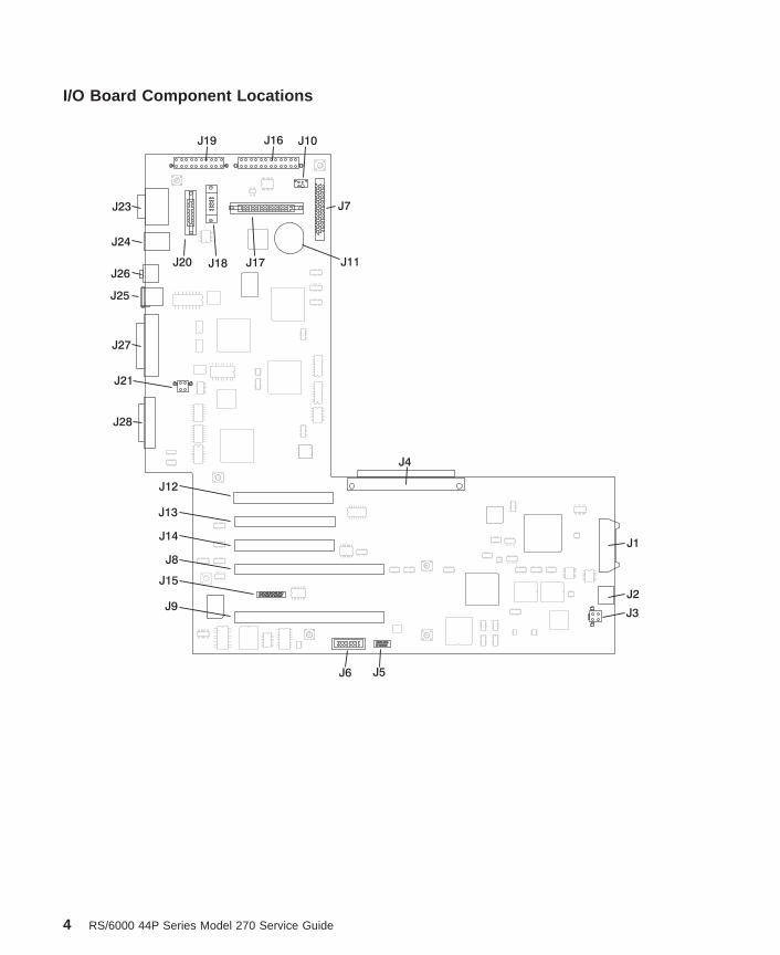
I/O Board Component Locations
J1
J2
J3
J4
J5J6
J7
J8
J9
J10
J11
J12
J13
J14
J15
J27
J21
J28
J16
J17J18
J19
J20
J23
J24
J25
J26
4 RS/6000 44P Series Model 270 Service Guide

J1 Operator panel power connector
J2 Operator panel audio connector
J3 I/O fan connector
J4 I/O board connector to system board
J5 VPD module connector
J6 ESP external connector
J7 Internal SCSI connector
J8, J9 64-bit PCI connectors
J10 CD-ROM audio connector
J11 Battery Socket
J12, J13, J14 32-bit PCI connectors
J15 Service processor external connector
J16 Power connector
J17 Diskette drive connector
J18 Tablet connector
J19 Power connector
J20 AUI Ethernet connector
J21 CEC fan connector
J23 Serial port connectors
J24 Keyboard/Mouse connector
J25 RJ45 Ethernet connector
J26 Audio in/out
J27 Parallel port connector
J28 External SCSI connector
Chapter 1. Reference Information 5

SCSI IDs and Bay Locations
Index Bay Location Drive Name SCSI ID
1 Bay D2 CD-ROM SCSI ID 1
2 Bay D3 Media device SCSI ID 0
3 Bay D1 Diskette drive Non-SCSI
4 Bay D4 Disk drive SCSI ID 9
5 Bay D5 Disk drive SCSI ID 8
Note: The SCSI bus IDs listed are the recommended values. The SCSI IDs shown formedia devices indicate how the devics are set when shipped from the factory.Field installations might not comply with these recommendations.
1
2
3
4
5
6 RS/6000 44P Series Model 270 Service Guide

System Board Locations
J1 System board connector to I/O board
J2 Memory card 2 connector
J3 Memory card 1 connector
J5 Power supply connector
J6 Processor card connector #1 (Primary)
J7 Power supply connector
J8 Processor card connector #2
Memory Card Locations
Note: Memory modules must be installed in pairs and in the correct slot configuration.(Slots J1 and J2, J3 and J4, J5 and J6, and so on.)
J1
J2
J3
J5
J6 J7
J8
Slot J1
Slot J3Slot J4
Slot J2
Slot J5Slot J6
Slot J9 Slot J10
Slot J11 Slot J12
Slot J13 Slot J14
Slot J15 Slot J16
Slot J7Slot J8
Chapter 1. Reference Information 7

Operator Panel
1 Power-On Switch
2 Reset Switch
3 Power-On LED
4 Disk Drive Activity LED
5 Display
6 Headset Receptacle
7 Microphone Receptacle
1 2
3
4
5 6 7
8 RS/6000 44P Series Model 270 Service Guide

System Cables
Note: P3 cable goes into designated socket J19. P4 cable goes into designated socketJ16.
Location CodesThis system unit uses physical location codes in conjunction with AIX location codes toprovide mapping of the failing field replaceable units. The location codes are producedby the system unit’s firmware and AIX.
Physical Location CodesPhysical location codes provide a mapping of logical functions in a platform (orexpansion sites for logical functions, such as connectors or ports) to their specificlocations within the physical structure of the platform.
Location Code FormatThe location code is an alphanumeric string of variable length, consisting of a series oflocation identifiers, separated by a dash (-), slash (/), or a pound sign (#) character. Theseries is hierarchical; that is, each location identifier in the string is a physical or logicalchild of the one preceding it.
I/O BoardI/O Board
Power SupplyPower Supply
Fan
CD ROMCD ROM
Media
Device
Media
Device
Operator
Panel
Operator
PanelSystem BoardSystem Board
Disk
Drives
Disk
Drives
Fan
Fan
Diskette
P1
P2
P3 P4 J10
J7J17
P5
Power
Audio
Audio
Power
Power
Power
SCSI
SCSI
SCSI
P6
J7 J5
Data
J3
J2
J1J21
J19 J16
Backplane
Chapter 1. Reference Information 9

v The - (dash) separator character represents a normal structural relationship wherethe child is a separate physical package and it plugs into (or is connected to) theparent. For example, P1-C1 is a processor card (C1) plugged into a planar (P1), orP1-M1 is a memory card (M1) plugged into a planar (P1).
v The / (slash) separator character separates the base location code of a function fromany extended location information. A group of logical devices can have the samebase location code because they are all on the same physical package, but mayrequire extended location information to describe the connectors they support. Forexample, P2/S1 describes the location of the serial port 1 controller and its connector(S1), which is located on planar P2 (its base location code), but the / indicates thatfurther devices can be connected to it at the external S1 serial connector. Thekeyboard controller and its connector likewise have location code P2/K1, whichmeans they have the same base location code (P2) as serial port 1, but a differentexternal connector. In contrast, the location code P2-K1 actually points to the deviceconnected to connector K1; that is, the keyboard. The location code P2/Z1 indicatesan integrated SCSI controller which drives connector Z1, while location codes ofP2-Z1-... point to the actual SCSI bus and devices.
v The # (pound sign) separator character indicates a cable connection between aconnector and parent.
The following are examples:
v P1-C1 identifies processor card C1 plugged into planar P1.
v P1-M1 identifies memory card M1 plugged into planar P1.
v P2/S1 identifies serial port 1 controller on I/O board P2, or the connector for serialport 1.
v P1-K1 identifies a keyboard attached to connector K1 on planar P1.
v P2/Z1 identifies an integrated SCSI controller on planar P2 which drives connectorZ1.
v P2-Z1-... points to the actual SCSI bus and devices attached to Z1.
The . (period) identifies sub locations (DIMMs on a memory card, or SCSI addresses).The following are examples:
v P1-M1.4 identifies memory DIMM 4 on memory card 1 plugged into planar P1.
v P1-C1.1 identifies processor 1 on processor card 1 plugged into planar P1.
v P2-Z1-A3.1 identifies a SCSI device with SCSI address of LUN 1 at SCSI ID 3attached to SCSI bus 1, which is integrated on planar P2.
v P2.1 identifies a riser card plugged into planar P2.
AIX Location CodesThe basic formats of the AIX location codes are as follows:
v For non-SCSI devices/drives:
– AB-CD-EF-GH
v For SCSI devices/drives:
– AB-CD-EF-G,H
10 RS/6000 44P Series Model 270 Service Guide

For planars, cards, and non-SCSI devices, the location code is defined as follows:
AB-CD-EF-GH| | | || | | Device/FRU/Port ID| | Connector ID| devfunc Number, Adapter Number or Physical LocationBus Type or PCI Parent Bus
v The AB value identifies a bus type or PCI parent bus as assigned by the firmware.
v The CD value identifies adapter number, the adapter’s devfunc number, or physicallocation. The devfunc number is defined as the PCI device number times 8, plus thefunction number.
v The EF value identifies a connector.
v The GH value identifies a port, address, device, or FRU.
Adapters and cards are identified only with AB-CD.
The possible values for AB are:
00 Processor bus01 ISA bus02 EISA bus03 MCA bus04 PCI bus used in the case where the PCI bus cannot be identified05 PCMCIA busesxy For PCI adapters where x is equal to or greater than 1. The x and y are characters in the
range of 0-9, A-H, J-N, P-Z (O, I, and lower case are omitted) and are equal to the parentbus’s ″ibm, aix-location″ open firmware property.
The possible values for CD depend on the adapter/card:
v For pluggable PCI adapters/cards, CD is the device’s devfunc number (PCI devicenumber times 8, plus the function number). The C and D are characters in the rangeof 0-9, and A-F (hex numbers). Location codes therefore uniquely identify multipleadapters on individual PCI cards.
v For pluggable ISA adapters, CD is equal to the order of the ISA cardsdefined/configured either by SMIT or the ISA Adapter Configuration Service Aid.
v For integrated ISA adapters, CD is equal to a unique code identifying the ISAadapter. In most cases, this code is equal to the adapter’s physical location code. Incases where a physical location code is not available, CD will be FF.
EF is the connector ID, used to identify the adapter’s connector to which a resource isattached.
GH is used to identify a port, device, or FRU. For example:
v For async devices, GH defines the port on the fanout box. The values are 00 to 15.
v For a diskette drive, H identifies either diskette drive 1 or 2. G is always 0.
v For all other devices, GH is equal to 00.
Chapter 1. Reference Information 11

For integrated adapters, EF-GH is the same as the definition for a pluggable adapter.For example, the location code for a diskette drive is 01-D1-00-00. A second diskettedrive is 01-D1-00-01.
For SCSI devices, the location code is defined as follows:
AB-CD-EF-G,H| | | | || | | | Logical Unit address of the SCSI Device| | | Control Unit Address of the SCSI Device| | Connector ID| devfunc Number, Adapter Number or Physical LocationBus Type or PCI Parent Bus
Where
AB-CD-EF are the same as non-SCSI devices.
G defines the control unit address of the device. Values of 0 to 15 are valid.
H defines the logical unit address of the device. Values of 0 to 255 are valid.
A bus location code that is also generated as ’00-XXXXXXXX’ where XXXXXXXX isequivalent to the node’s unit address.
Examples of physical location codes displayed by AIX are as follows:
v First processor card plugged into planar 1:
P1-C1
v Second memory card in planar P1:
P1-M2
v Memory DIMM 12 on second memory card plugged into planar P1:
P1-M2.12
Examples of AIX location codes displayed are as follows:
v Integrated PCI adapter as follows:
10-80 Ethernet10-60 Integrated SCSI Port 1 (internal)10-88 Integrated SCSI Port 2 (external)
v Pluggable PCI adapters as follows:
20-58 to 20-5F Any PCI card in slot 120-60 to 20-67 Any PCI card in slot 210-68 to 10-6F Any PCI card in slot 310-70 to 10-77 Any PCI card in slot 410-78 to 10-7F Any PCI card in slot 5
v Integrated ISA adapters as follows:
01-D1 Diskette adapter01-R1 Parallel port adapter01-S1 Serial port 1 adapter
12 RS/6000 44P Series Model 270 Service Guide

01-S2 Serial port 2 adapter01-S3 Serial port 3 adapter01-K1 Keyboard adapter
v Device attached to SCSI controller
10-60-00-4,0 Device attached to integrated SCSI controller 1:
AIX and Physical Location Code Reference Table
AIX
Location
Codes
Physical
Location
Codes
Serial
Mouse
01-S1
01-S2
Keyboard
Parallel
01-K1-01
01-K1-00
10-88
01-R1
P2/S1
P2/S2
P2/K1
P2/Q1
P2/E1
P2/E1
P2/R1
P2/Z2
10-78 to 10-7F
or
1F-XX
10-70 to 10-77
or
1E-XX
10-68 to 10-6F
or
1D-XX
20-60 to 20-67
or
2C-XX
20-58 to 20-5F
or
2B-XX
PCI 32-Bit
PCI 32-Bit
PCI 32-Bit
PCI 64-Bit
PCI 64-Bit
Tablet01-Q1-00
P2-I5
P2-I4
P2-I3
P2-I2
P2-I1
P2/O1
P2/F1
RJ45 Ethernet
CEC Fan
Ext SCSI
10-80
10-80AUI Ethernet
01-Q2-00P2/Q2
Integrated Audio
Chapter 1. Reference Information 13

P2/D1
P2/Z1
P1-C1
P1-M1
P1-M2
Diskette Drive
Processor Card
(primary)
Processor Card
Physical
Location
Codes
AIX
Location
Codes
P2/L1
Memory Card
Memory Card
Operator Panel
10-60Internal SCSI
P2/F2I/O Fan
01-D1
P1-C2
14 RS/6000 44P Series Model 270 Service Guide

FRU Name AIX LocationCode
PhysicalLocation Code
PhysicalConnection
LogicalIdentification
Central Electronics Complex (CEC)
System board 00-00 P1
Processor card 1 00-00 and 00–01(2–way card)
P1-C1 Processorconnector J6
CPU ID proc0and proc1 (2-waycard)
Processor card 2 00-02 and 00–03(2–way card)
P1-C2 Processorconnector J8
CPU ID proc2and proc3 (2-waycard)
Memory card 1 00-00 P1-M1 Memory cardconnector J3
Memory card 1modules 1 thru 16
00-00 P1-M1.1 throughP1-M1.16
Memory cardsocketsJ1,J2,J3,J4,J5,J6,J7,J8J9,J10,J11,J12,J13,J14,J15,J16
Extents:8L,8H,10L,10H,12L,12H,14L,14H9L,9H,11L,11H,13L,13H,15L,15H
Memory card 2 00-00 P1-M2 Memory cardconnector J2
Memory card 2modules 1 thru 16
00-00 P1-M2.1 throughP1-M2.16
Memory cardsocketsJ1,J2,J3,J4,J5,J6,J7,J8J9,J10,J11,J12,J13,J14,J15,J16
Extents:8L,8H,10L,10H,12L,12H,14L,14H9L,9H,11L,11H,13L,13H,15L,15H
I/O board 00-00 P2
Integrated Devices
Diskette Drive 01-D1-00-00 P2-D1 I/O boardConnector J13
Base Address0x0310
Keyboard 01-K1-00-00 P2-K1 I/O boardconnector J24
Base Address0x0060
Mouse 01-K1-01-00 P2-O1 I/O boardconnector J24
0x0060
Diskette Port 01-D1 P2/D1 I/O boardconnector J17
0x03f0
Keyboard Port 01-K1-00 P2/K1 I/O boardconnector J24
0x0060
Mouse Port 01-K1-01 P2/O1 I/O boardconnector J24
0x0060
Tablet Port 01-Q1-01-00 P2/Q1 I/O boardconnector J18
0x0060
Audio 01-Q2-00 P2/Q2 I/O boardconnector J26
0x0060
Serial Port 1 01-S1 P2/S1 I/O boardconnector J23
0x0318
Chapter 1. Reference Information 15

FRU Name AIX LocationCode
PhysicalLocation Code
PhysicalConnection
LogicalIdentification
Serial Port 2 01-S2 P2/S2 I/O boardconnector J23
0x0218
Parallel Port 01-R1 P2/R1 I/O boardconnector J27
0x0378
AUI Ethernet Port 10-80 P2/E1 I/O boardconnector J20
Host Bridge ID00,Device 06
RJ45 EthernetPort
10-80 P2/E1 I/O boardconnector J25
Host Bridge ID00,Device 06
Internal SCSI Port 10-60 P2/Z1 I/O boardconnector J7
Host Bridge ID00,Device 02
External SCSIPort
10-88 P2/Z2 I/O boardconnector J28
Host Bridge ID00,Device 07
Pluggable Adapters
Card in PCI Slot1P
20-58 to 20-5F or2B-xx
P2-I1 I/O boardconnector J9
Host Bridge ID01,Device 01
Card in PCI Slot2P
20-60 to 20-67 or2C-xx
P2-I2 I/O boardconnector J8
Host Bridge ID01,Device 02
Card in PCI Slot3P
10-68 to 10-6F or1D-xx
P2-I3 I/O boardconnector J14
Host Bridge ID00,Device 03
Card in PCI Slot4P
10-70 to 10-77 or1E-xx
P2-I4 I/O boardconnector J13
Host Bridge ID00,Device 04
Card in PCI Slot5P
10-78 to 10-7F or1F-xx
P2-I5 I/O boardconnector J12
Host Bridge ID00,Device 05
SCSI Devices
Base CD-ROM(Bay D1)
10-60-00-1, 0 P2-Z1-A1 Primary SCSI busID 1 (refer to thenote at the end ofthis table)
Media Device inBay D2
10-60-00-0,0 P2-Z1-A0 Primary SCSI busID 0 (refer to thenote at the end ofthis table)
DASD in Bay D4 10-60-00-9,0 P2-Z1-A9 Primary SCSI busID 9
DASD in Bay D5 10-60-00-8,0 P2-Z1-A8 Secondary SCSIbus ID 8
Fans
I/O fan F2 Fan connector J3at system board
CEC fan F1 Fan connectorJ21 at systemboard
16 RS/6000 44P Series Model 270 Service Guide

FRU Name AIX LocationCode
PhysicalLocation Code
PhysicalConnection
LogicalIdentification
I/O fan connector P2/F2 Fan connector J3at system board
CEC fanconnector
P2/F1 Fan connectorJ21 at systemboard
Operator Panel
Operator panel L1 I/O boardconnector J1
Operator panelConnector
P2/L1 I/O boardconnector J1
Power Supply
Power supply V1
Battery
Battery V2 I/O boardconnector J11
Notes:
1. The physical location code for the PCI slots, when empty, uses the P1/Ix notation, where the’/’ identifies an integrated device (in this case the empty slot). A PCI device plugged into theslot uses the P1-Ix notation, where the ’-’ identifies a plugged device.
2. The SCSI bus IDs are the recommended values. The SCSI IDs shown for media devicesindicate how the devices are set when they are shipped from the factory. Field installationsmay not comply with these recommendations.
SpecificationsThe mechanical packaging, cooling, power supply, and environmental requirements forthe server are as follows:
Dimensionsv With pedestal:
– Height - 615 mm (24.2 inches)
– Depth - 681 mm (26.8 inches)
– Width - 340 mm (13.4 inches)
v Without pedestal:
– Height - 610 mm (24.0 inches)
– Depth - 681 mm (26.8 inches)
– Width - 221 mm (8.7 inches)
Chapter 1. Reference Information 17

WeightConfiguration-dependent
Operating Environment - Class Bv Temperature - 16° to 32°C (60° to 90°F)
v Humidity - 8% to 80% noncondensing
v Maximum Altitude - 2135 m (7000 feet)
Power Source Loadingv Typical EMC Configuration - 0.3 kVA
v Maximum - 0.5 kVA
Power Requirementsv Typical - 275 watts
v Maximum - 640 watts
Power Factor0.89 - 0.98
Operating Voltagev 100 to 127V ac; 50 to 60 Hz
v 200 to 240V ac; 50 to 60 Hz
Heat Output (Maximum)v Typical - 400 Btu/hr
v Maximum - 794 Btu/hr
Acousticsv 6.0 Bels operating
v 5.5 Bels idle
18 RS/6000 44P Series Model 270 Service Guide

Power CablesTo avoid electrical shock, a power cable with a grounded attachment plug is provided.Use only properly grounded outlets.
Power cables used in the United States and Canada are listed by Underwriter’sLaboratories (UL) and certified by the Canadian Standards Association (CSA). Thesepower cords consist of the following:
v Electrical cables, Type SVT or SJT.
v Attachment plugs complying with National Electrical Manufacturers Association(NEMA) 5-15P, that is:
″For 115 V operation, use a UL listed cable set consisting of a minimum 18 AWG,Type SVT or SJT three-conductor cord a maximum of 15 feet in length and a parallelblade, grounding type attachment plug rated at 15 A, 125 V.″
″For 230 V operation in the United States use a UL listed cable set consisting of aminimum 18 AWG, Type SVT or SJT three-conductor cable a maximum of 15 feet inlength, and a tandem blade, grounding type attachment plug rated at 15 A, 250 V.″
v Appliance couplers complying with International Electrotechnical Commission (IEC)Standard 320, Sheet C13.
Power cables used in other countries consist of the following:
v Electrical cables, Type HD21.
v Attachment plugs approved by the appropriate testing organization for the specificcountries where they are used.
″For units set at 230 V (outside of U.S.): use a cable set consisting of a minimum 18AWG cable and grounding type attachment plug rated 15 A, 250 V. The cable setshould have the appropriate safety approvals for the country in which the equipmentwill be installed and should be marked ′HAR’.″
Refer to “Chapter 10. Parts Information” on page 267 to find the power cables that areavailable.
Chapter 1. Reference Information 19

Service Inspection GuidePerform a service inspection on the system when:
v The system is inspected for a maintenance agreement.
v Service is requested and service has not recently been performed.
v An alterations and attachments review is performed.
v Changes have been made to the equipment that may affect the safe operation of theequipment.
v External devices with their own power cables have those cables attached.
If the inspection indicates an unacceptable safety condition, the condition must becorrected before anyone can service the machine.
Note: The correction of any unsafe condition is the responsibility of the owner of thesystem.
Perform the following checks:
1. Check the covers for sharp edges and for damage or alterations that expose theinternal parts of the system unit.
2. Check the covers for proper fit to the system unit. They should be in place andsecure.
3. Gently rock the system unit from side to side to determine if it is steady.
4. Set the power switch of the system unit to Off.
5. Remove the covers.
6. Check for alterations or attachments. If there are any, check for obvious safetyhazards such as broken wires, sharp edges, or broken insulation.
7. Check the internal cables for damage.
8. Check for dirt, water, and any other contamination within the system unit.
9. Check the voltage label on the back of the system unit to ensure that it matchesthe voltage at the outlet.
10. Check the external power cable for damage.
11. With the external power cable connected to the system unit, check for 0.1 ohm orless resistance between the ground lug on the external power cable plug and themetal frame.
12. Perform the following checks on each device that has its own power cables:
a. Check for damage to the power cord.
b. Check for the correct grounded power cable.
c. With the external power cable connected to the device, check for 0.1 ohm orless resistance between the ground lug on the external power cable the metalframe of the device.
13. Install the covers.
20 RS/6000 44P Series Model 270 Service Guide

Chapter 2. Diagnostics Overview
44P Series Model 270 systems use an integrated set of software diagnostic proceduresto facilitate isolation of failing components and system maintenance. This book, alongwith the RS/6000 Diagnostic Information for Multiple Bus Systems, is the basis of thediagnostic procedures for 44P Series Model 270 servers. In particular, “Chapter 4.Checkpoints” on page 71, “Chapter 5. Error Code to FRU Index” on page 93,“Chapter 6. Loading the System Diagnostics” on page 145, and “Chapter 10. PartsInformation” on page 267, in this book are important for the trained servicerepresentative to understand and use when isolating a failure on the system.
The manufacturer recommends that systems configured with 4GB of memory or greaterhave access to a 4mm or 8mm tape drive for submission of system dump information ifrequired. This function can be accomplished through locally attached ornetwork-attached devices, as appropriate.
Maintenance Analysis Procedures (MAPs)Maintenance Analysis Procedures (MAPs) guide the trained service person through the44P Series Model 270 server. These MAPs are the entry point for all isolation and errorrecovery procedures. The MAPs are consistent with existing procedures and methods.44P Series Model 270 servers use a set of integrated procedures, mentioned earlier, towhich the MAPS are the primary entry point.
The MAPS are as follows:
v Entry MAP
v Quick Entry MAP
v Problem Determination MAP
v Power MAP
v Minimum Configuration MAP
The Entry Map is the starting point for problem determination. The purpose of this MAPis to quickly point to the appropriate MAP or service reference information either in thisbook, or in the common book set, which includes the RS/6000 Diagnostic Informationfor Multiple Bus Systems and thePCI Adapter Placement Reference.
The Quick Entry MAP is a subset of the Entry MAP and helps to save time for sometypes of problems.
The Problem Determination MAP provides a structured analysis method to get an errorcode if one is not provided by the customer, or if diagnostics cannot be loaded.
The Power MAP deals with isolation of components to diagnose a power problem.Power problems can be related to powering up and down the system, or power failuresthat occur after power is turned on.
21

The Minimum Configuration MAP is used to locate defective components not found bynormal diagnostics or error-isolation methods. This MAP provides a systematic methodof isolation to the failing item or items.
Checkpoints44P Series Model 270 servers use various types of checkpoints, error codes, andSRNs, which are referred to throughout this book (primarily in “Chapter 4. Checkpoints”on page 71, “Chapter 5. Error Code to FRU Index” on page 93, “Chapter 6. Loading theSystem Diagnostics” on page 145, and “Chapter 10. Parts Information” on page 267).These codes may appear in the service processor boot progress log, the AIX error log,and the operator panel display. Understanding the definition and relationships of thesecodes is important to the service personnel who are installing or maintaining 44P SeriesModel 270 servers.
Codes that can appear on the operator panel or in error logs are as follows:
CheckpointsCheckpoints display in the operator panel from the time AC power isconnected to the system until the AIX login prompt is displayed after asuccessful operating system boot. These checkpoints have the following forms:
E000 - E075These checkpoints display from the time ac power is connected to thesystem until the
OK
prompt displays on the operator panel display. During this time, theservice processor performs self-test and NVRAM initialization.
E0A0 - E0E1When power up is initiated, the service processor starts built-inself-test (BIST) on the central eectronics complex (CEC). VPD dataare read.
E0E2 - E2xxThis range indicates that the system processor is in control and isinitializing system resources.
E3xx These codes indicate that the system processor is running memorytests.
E1xx The system firmware attempts to boot from devices in the boot list.Control is passed to AIX when E105 (normal mode boot) or E15B(service mode boot) displays on the operator panel display.
0xxx 0xxx codes are AIX checkpoints and configuration codes. Locationcodes may also be shown on the operator panel display during thistime.
22 RS/6000 44P Series Model 270 Service Guide

Error CodesIf a fault is detected, an 8-digit error code is displayed in the operator paneldisplay. A location may be displayed at the same time on the second line ofthe display.
Checkpoints can become error codes if the system fails to advance past thepoint at which the code was presented.
For a list of checkpoints, see “Chapter 4. Checkpoints” on page 71. Each entryprovides a description of the event and the recommended action if the systemfails to advance.
SRNs Service request numbers, in the form xxx-xxx, may also be displayed on theoperator panel display and be noted in the AIX error log.
SRNs are listed in the Diagnostic Information for Multiple Bus Systems.
FRU IsolationFor a list of error codes and recommended actions for each code, see “Chapter 5. ErrorCode to FRU Index” on page 93. These actions can refer to “Chapter 10. PartsInformation” on page 267, “Chapter 3. Maintenance Analysis Procedures (MAPs)” onpage 27, or provide informational message and directions. If a replacement part isindicated, the part name is included. The respective AIX and physical location codesare listed for each occurrence as required. For a list of locations codes, see “AIX andPhysical Location Code Reference Table” on page 13.
To determine part numbers and view component diagrams, see “Chapter 10. PartsInformation” on page 267. The beginning of the chapter provides a parts index with thepredominant field replaceable units (FRUs) listed by name. The remainder of thechapter provides illustrations of the various assemblies and components that make up44P Series Model 270 systems.
Service Director for the RS/6000Service support for the 44P Series Model 270 can be enhanced through the use of theapplication program, Service Director for the RS/6000. This application provides anumber of advantages for the 44P Series Model 270 customer, including automaticerror reporting and analysis without customer intervention. The Service Director kit isprovided with the 44P Series Model 270 server and includes the following:
v Service Director for the RS/6000 program on CD-ROM
v The CE Information Guide for Service Director
For more details on Service Director for the RS/6000, see the CE Information Guide,
Chapter 2. Diagnostics Overview 23

Using the Service Processor and Service Director FeaturesThe service processor and Service Director features protect users against unnecessarysystem downtime by advising support personnel (both internal and external) of anyunexpected changes in the system environment. In combination, the two featuresprovide a flexible solution to automated system maintenance.
Service ProcessorThe service processor runs on its own power boundary and continually monitorshardware attributes, the AIX operating system, and the environmental conditions withinthe system. Any system failure that prevents the system from coming back to anoperational state (a fully functional AIX operating system) is reported by the serviceprocessor. The service processor is controlled by firmware and does not require the AIXoperating system to be operational to perform its tasks. If any system failures aredetected, the service processor can take predetermined corrective actions. Themethods of corrective actions are as follows:
v Surveillance
v Call home
v AIX operating system monitoring
Surveillance is a function in which the service processor monitors the system throughheartbeat communication with the system firmware. The heartbeat is a periodic signalthat the firmware can monitor. During system startup, the firmware surveillance monitoris automatically enabled to check for heartbeats from the firmware. If a heartbeat is notdetected within a default period, the service processor cycles the system power andattempts to restart until the system either restarts successfully, or a predetermined retrythreshold is reached. In the event the service processor is unsuccessful in bringing thesystem online (or in the event that the user asked to be alerted to any serviceprocessor-assisted restarts), the system can call home to report the error.
The Call-Home function can be initialized to call either a service center telephonenumber, a customer administration center, or a digital pager telephone number. Theservice processor can be configured to stop at the first successful call to any of thenumbers listed, or can be configured to call every number provided. If connected to theservice center, the service processor transmits the relevant system information (thesystem’s serial number and model type) and service request number (SRN). Ifconnected to a digital pager service, the service processor inputs a customer voicetelephone number defined by the customer. An established sequence of digits or thetelephone number to a phone near the failed system could be used to signal a systemadministrator to a potential system failure.
During normal operations, the service processor can also be configured to monitor theAIX operating system. If AIX does not respond to the service processor heartbeat, theservice processor assumes the operating system is hung. The service processor canautomatically initiate a restart and, if enabled, initiate the call home function to alert theappropriate people to the system hang. Enabling operating system surveillance alsoenables AIX to detect any service processor failures and report those failures to theService Director application.
24 RS/6000 44P Series Model 270 Service Guide

Unlike the Service Director, the service processor cannot be configured in aclient/server environment where one system can be used to manage all dial-outfunctionally for a set of systems.
Prior to installing the Service Director feature, ensure that you have the latest levels ofsystem and service processor firmware. You also need a correctly configured modem.For more information on configuring a modem, see “Appendix E. ModemConfigurations” on page 289.
Service DirectorThe Service Director is a software extension to the AIX operating system that monitorsthe system while the AIX operating system is running. The Service Director monitorsand analyzes all recoverable system failures, and, if needed, can automatically place aservice call to a service center (without user intervention).
The service center receives the machine type, model, and serial number, host name,SRN, and a problem description. The service center analyzes the problem report and, ifwarranted, dispatches a service person to the customer site. The service center alsodetermines if any hardware components must be ordered prior to the service person’sarrival.
The Service Director code also gives the user the option to establish a single system asthe problem-reporting server. A single system, accessible over the user network, can beused as the central server for all the other systems on the local area network (LAN) thatare running the Service Director application. If the Service Director application on aremote client decides a service request needs to be placed, the client forwards theinformation to the Service Director server, which dials the service center telephonenumber from its locally attached modem. In this scenario, the user only needs tomaintain a single analog line for providing call-out capabilities for a large set of servers.
A modem is required for enabling automated problem reporting to the IBM servicecenter. Configuration files for several types of modems are included as part of theService Director package. Refer to “Appendix E. Modem Configurations” on page 289for more information on configuring your modem.
Chapter 2. Diagnostics Overview 25

26 RS/6000 44P Series Model 270 Service Guide

Chapter 3. Maintenance Analysis Procedures (MAPs)
This chapter contains Maintenance Analysis Procedures (MAPs).
Notes:
1. When possible, run online diagnostics in service mode. Online diagnostics performadditional functions, compared to standalone diagnostics. This ensures that theerror state of the system is captured in NVRAM (non-volatile random accessmemory) for your use in fixing the problem. The AIX error log and SMIT are onlyavailable when diagnostics are run from the hard drive.
2. If more than eight digits are displayed in the operator panel, use only the first eightdigits to find the error in the tables. The digits that display beyond the first eightdigits are location codes that can assist you in diagnosing the problem. See“Location Codes” on page 9.
3. Licensed programs frequently rely on network configuration and system informationstored on the VPD (vital product data) module on the operator panel controlassembly. If the MAPs indicate that the operator panel control assembly should bereplaced, swap the VPD module from the old operator panel to the new one. If theexisting VPD module must be replaced, call technical support for recoveryinstructions. If recovery is not possible, notify the system owner that new keys forlicensed programs may be required.
4. If a network adapter or the I/O board is replaced, the network administrator must benotified so that the client IP addresses used by the server can be changed. Inaddition, the operating system configuration of the network controller might need tobe changed in order to enable system startup. Also check to ensure that any clientor server that addresses this system is updated.
Quick Entry MAPUse the following table to determine your starting point.
If you replace FRUs or perform an action and the problem is still not corrected, go to″Map1540: Minimum Configuration″.“MAP 1540: Minimum Configuration” on page 50unless otherwise indicated in the tables.
If you replace FRUs or perform an action and the problem is corrected, go to "MAP410: Repair Checkout" in the RS/6000 Diagnostic Information for Multiple Bus Systems.
27

Quick Entry MAP Table of Contents
Problem Description Page No.
Service Actions 28
System Stops With an 8-Digit Number Displayed 28
System Stops With a 4-Digit Number Displayed 28
System Stops With a 3-Digit Number Displayed 29
System Stops or Hangs With Alternating Numbers Displayed in theOperator Display Panel.
29
Display Problem (Distortion, Blurring, Etc.) 29
Power and Cooling Problems 30
Flashing 888 in Operator Panel Display 30
Other Symptoms or Problems 30
You Cannot Find the Symptom in this Table 33
Symptom Action
Service Actions
You have parts to exchange or a correctiveaction to perform.
1. Go to “Chapter 9. Removal and ReplacementProcedures” on page 221.
2. Go to "MAP 410: Repair Checkout" in theRS/6000 Diagnostic Information for MultipleBus Systems.
You need to verify that a part exchange orcorrective action corrected the problem.
Go to "MAP 410: Repair Checkout" in theRS/6000 Diagnostic Information for Multiple BusSystems.
You need to verify correct system operation. Go to "MAP 410: Repair Checkout" in theRS/6000 Diagnostic Information for Multiple BusSystems.
System Stops With A 8-Digit Number Displayed
The system stops with an 8-digit error codedisplayed in the operator panel display or onthe console.
Record the error code. Go to “Chapter 5. ErrorCode to FRU Index” on page 93.
System Stops With A 4-Digit Number Displayed
28 RS/6000 44P Series Model 270 Service Guide

Symptom Action
The system stops and a 4-digit number isdisplayed in the operator panel display or onthe console.
If the number displayed has the format ″E0xx″then go to “Service Processor Checkpoints” onpage 71.
If the number displayed is in the range″E1xx-EFFF″, make note of any location codethat is displayed on the second line of theoperator panel. If the location code indicates acard slot (for example P2-I3), replace the card inthe indicated slot. If this does not correct theproblem, then go to “Firmware Checkpoints” onpage 75.
For all other numbers, record SRN 101-xxx,where xxx is the last three digits of the four-digitnumber displayed in the operator panel, then goto the Fast Path MAP in the RS/6000 DiagnosticInformation for Multiple Bus Systems.Note: If the operator panel displays two sets ofnumbers, use the bottom set of numbers as theerror code.
System Stops With A 3-Digit Number Displayed
The system stops and a 3-digit numberdisplayed in the operator panel display or onthe console.
Record SRN 101-xxx, where xxx is three-digitnumber displayed in the operator panel, then goto the Fast Path MAP in the RS/6000 DiagnosticInformation for Multiple Bus Systems.
System Stops or Hangs With Alternating Numbers Displayed in the Operator Display Panel
The operator panel display alternatesbetween the code ″E1FD″ and another″Exxx″ code.
Record both codes. Go to ″E1FD″ in “FirmwareCheckpoints” on page 75.
The operator panel display alternatesbetween the codes ″E1DE″ and ″E1AD″.
Record both codes. Go to ″E1DE″ in “FirmwareCheckpoints” on page 75.
Display Problem (Blank, Distortion, Blurring, Etc.).
Chapter 3. Maintenance Analysis Procedures 29

Symptom Action
All display problems. v If using a graphics display:
1. Go to the problem determinationprocedures for the display.
2. If you do not find a problem, replace thedisplay adapter.
3. If you do not find a problem, suspect theI/O board. Go to “MAP 1540: MinimumConfiguration” on page 50.
v Using an ASCII terminal:
1. Make sure that the ASCII terminal isconnected to S1.
2. If problems persist, go to the problemdetermination procedures for the terminal.
3. If you do not find a problem, suspect theI/O board. Go to “MAP 1540: MinimumConfiguration” on page 50.
Power and Cooling Problems
The power LEDs on the operator panel andthe power supply do not start flashing within30 seconds of ac power application.
Go to “MAP 1520: Power” on page 45.
The power LEDs on the operator panel andthe power supply do not come on or stay on.
Go to “MAP 1520: Power” on page 45.
The power LEDs on the operator panel andthe power supply come on and stay on butthe system does not power on.
Go to “MAP 1520: Power” on page 45.
The cooling fan(s) do not come on or comeon but do not stay on.
Go to “MAP 1520: Power” on page 45.
Flashing 888 in Operator Panel Display
888 is displayed in the operator panel. Go to the Fast Path MAP in the RS/6000Diagnostic Information for Multiple Bus Systems.
Other Symptoms or Problems
You have OK displayed. The service processor is ready. Go to ″MAP0020: Problem Determination Procedure″ in theRS/6000 Diagnostic Information for Multiple BusSystems.
You have STBY displayed. The service processor is ready. The system wasshut down by the operating system and is stillpowered on. This condition can be requested bya privileged system user with no faults. Seeservice processor error log for possible operatingsystem fault indications.
30 RS/6000 44P Series Model 270 Service Guide

Symptom Action
The system POST indicators are displayed onthe system console; the system pauses andthen restarts. The term ″POST indicators″refers to the icons (graphic display) or devicemnemonics (ASCII terminal) that appearduring the power-on self-test (POST).
Go to “Boot Problems/Concerns” on page 89.
The system stops and POST indicators aredisplayed on the system console. The term″POST indicators″ refers to the icons (graphicdisplay) or device mnemonics (ASCIIterminal) that appear during the power-onself-test (POST).
Go to “MAP 1540: Minimum Configuration” onpage 50 to isolate the problem.
The system stops and the message″STARTING SOFTWARE PLEASE WAIT...″ isdisplayed on the ASCII terminal, or the bootindicator
is displayed on a graphics terminal.
Go to “Chapter 4. Checkpoints” on page 71.
The system does not respond to thepassword being entered, or the system loginprompt is displayed when booting in servicemode.
Verify that the password is being entered fromthe ASCII terminal or keyboard defined as thesystem console. If so, then the keyboard or itscontroller may be faulty.
v If entering the password from the keyboardwhich is attached to the system, replace thekeyboard. If replacing the keyboard does notfix the problem, replace the I/O board. (Seenote 4 on page 27.)
v If entering the password from a keyboardwhich is attached to an ASCII terminal, use theproblem determination procedures for theASCII terminal. Make sure the ASCII terminalis connected to S1. Replace the I/O board ifthese procedures do not reveal a problem.
v If the problem is fixed, go to "MAP 410: RepairCheckout" in the RS/6000 DiagnosticInformation for Multiple Bus Systems. If theproblem persists, go to “MAP 1540: MinimumConfiguration” on page 50 to isolate theproblem.
Chapter 3. Maintenance Analysis Procedures 31

Symptom Action
No codes are displayed on the operator panelwithin a few seconds of turning on thesystem. The operator panel is blank beforethe system is powered on.
Reseat the operator panel cable. If the problem isnot resolved, replace these parts in the followingorder:
1. Operator panel assembly. Update the VPDinformation in the new operator panel.
2. I/O board (See notes 4 on page 27.)
If the problem is fixed, go to "MAP 410:Repair Checkout" in the RS/6000 DiagnosticInformation for Multiple Bus Systems. If theproblem persists, go to “MAP 1540: MinimumConfiguration” on page 50 to isolate theproblem.
The SMS configuration list or boot sequenceselection menu shows more SCSI devicesattached to a controller/adapter than areactually attached.
A device may be set to use the same SCSI busID as the control adapter. Note the ID being usedby the controller/adapter (this can be checkedand/or changed via an SMS utility), and verifythat no device attached to the controller is set touse that ID.
If settings do not appear to be in conflict:
1. Replace the SCSI cable.
2. Replace the device.
3. Replace the SCSI adapter (or I/O board ifconnected to one of the two integrated SCSIcontrollers on the I/O board). (See note 4 onpage 27.
Note: In a ″twin-tailed″ configuration where thereis more than one initiator device (normallyanother system) attached to the SCSI bus, it maybe necessary to change the ID of the SCSIcontroller or adapter with the SystemManagement Services.
32 RS/6000 44P Series Model 270 Service Guide

Symptom Action
The System Management Services menu isdisplayed.
The device or media you are attempting to bootfrom may be faulty.
1. Check the SMS error log for any errors. Tocheck the error log:
a. Choose error log from the utilities menu.
b. If an error is logged, check the timestamp.
c. If the error was logged during the currentboot attempt, record it.
d. Look up the error in “Chapter 4.Checkpoints” on page 71 and perform thelisted action.
e. If no recent error is logged in the errorlog, continue to the next step below.
2. Try to boot from an alternate boot deviceconnected to the same controller as theoriginal boot device. If the boot succeeds,replace the original boot device. (Forremovable media devices try the media first.)
3. Go to “MAP 1540: Minimum Configuration” onpage 50.
You have a problem that does not prevent thesystem from booting.
Go to the Fast Path MAP in the RS/6000Diagnostic Information for Multiple Bus Systems.
You have an SRN. Go to the Fast Path MAP in the RS/6000Diagnostic Information for Multiple Bus Systems.
You suspect a cable problem. See the RS/6000 Adapters, Devices, and CableInformation for Multiple Bus Systems.
You do not have a symptom. Go to MAP 0020 in the RS/6000 DiagnosticInformation for Multiple Bus Systems.
You have not determined a symptom. Go to “MAP 1020: Problem Determination” onpage 34.
You Cannot Find the Symptom in this Table
All other problems. Go to “MAP 1020: Problem Determination” onpage 34.
Chapter 3. Maintenance Analysis Procedures 33

MAP 1020: Problem Determination
Purpose of This MAPUse this MAP to get an error code if you were not provided one by the customer or youare unable to load diagnostics. If you are able to load the diagnostics, go to MAP 0020in the RS/6000 Diagnostic Information for Multiple Bus Systems.
The service processor may have recorded one or more symptoms in its error log. It is agood idea to examine that error log before proceeding (see Service Processor SystemInformation Menu).
Be prepared to record code numbers and use those numbers in the course of analyzinga problem. Go to “Step 1020-1” on page 35.
The service processor may have been set by the user to monitor server operations andto attempt recoveries. You can disable these actions while you diagnose and servicethe system. You can use that same service aid to restore the settings at the end of yourservice action.
In case the service processor settings were not saved by the user, if you disable them,make notes of their current settings so that you can restore them before you leave.
In addition to the parameters in the table below, you might want to disconnect themodem to prevent incoming signals that could cause the system to power on.
Following are the service processor settings. The service processor menus aredescribed in “Service Processor Menus” on page 149.
Surveillance From the Service Processor Setup Menu, go tothe Surveillance Setup Menu and disablesurveillance.
Unattended Start Mode From the Service Processor System PowerControl Menu, disable unattended start mode.
Reboot Policy From the System Power Control Menu, go tothe Reboot/Restart Policy Setup Menu and set:
1. Number of reboot attempts to 0 (zero)
2. Use OS-Defined restart policy to No
3. Enable supplemental restart policy to No.
Call Out From the Call-In/Call-Out Setup Menu, go tothe Serial Port Selection Menu and disablecall-out on both serial ports.
34 RS/6000 44P Series Model 270 Service Guide

Step 1020-1The following steps analyze a failure to load the diagnostic programs.
Note: You are asked questions regarding the operator panel display. You are alsoasked to perform certain actions based on displayed POST indicators.
1. Insert the diagnostic CD-ROM into the CD-ROM drive.
2. Turn off the power.
3. Turn on the power.
4. When the keyboard indicator is displayed (the word keyboard on an ASCII terminalor the keyboard icon on a graphical display), press the F5 key on the directlyattached keyboard or the number 5 key on an ASCII terminal.
5. Enter a password, if you are requested.
6. Wait until the diagnostics are loaded or the system appears to stop.
7. Find your symptom in the following table. Then follow the instructions given in theAction column.
Symptom Action
The diskette LED is blinking rapidly, or EIEA orEIEB is displayed on the operator panel.
The flash EPROM data is corrupted. Run therecovery procedure for the flash EPROM. See“Firmware Recovery” on page 205.
The system stops with a prompt to enter apassword.
Enter the password. You are not allowed tocontinue until a valid password has beenentered. When you have entered a validpassword, go to the beginning of this table andwait for one of the other conditions to occur.
The diagnostic operating instructions aredisplayed.
Go to MAP 0020 in the RS/6000 DiagnosticInformation for Multiple Bus Systems.
The system login prompt is displayed. You may not have pressed the correct key oryou may not have pressed the key soonenough when you were to indicate a servicemode IPL of the diagnostic programs. If thiswas the case, start over at the beginning of thisstep.Note: Perform the system shutdown procedurebefore turning off the system.
If you are sure you pressed the correct key in atimely manner, go to “Step 1020-2” on page 37.
The system does not respond when thepassword is entered.
Go to “Step 1020-2” on page 37.
Chapter 3. Maintenance Analysis Procedures 35

Symptom Action
The system stopped and a POST indicator isdisplayed on the system console and an 8-digiterror code is not displayed.
If the POST indicator represents:
v Memory, record error code M0MEM002.
v Keyboard, record error code M0KBD000.
v SCSI, record error code M0CON000.
v Network, record error code M0NET000.
v Speaker (audio), record error codeM0BT0000.
Go to “Step 1020-3” on page 38.
The system stops and a 4-digit number isdisplayed in the operator panel display.
If the number displayed has the format ″E0xx″then go to “Service Processor Checkpoints” onpage 71. If it is in the range ″E1xx-EFFF″ thengo to “Firmware Checkpoints” on page 75.
For all other numbers record SRN 101-xxx,where xxx is the last three digits of thefour-digit number displayed in the operatorpanel, then go to the Fast Path MAP in theRS/6000 Diagnostic Information for Multiple BusSystems.Note: If the operator panel displays two sets ofnumbers, use the bottom set of numbers as theerror code.
The System Management Services isdisplayed.
Go to “Step 1020-4” on page 38.
All other symptoms. If you were directed here from the Entry MAP,go to “MAP 1540: Minimum Configuration” onpage 50. Otherwise, find the symptom in the“Quick Entry MAP” on page 27.
36 RS/6000 44P Series Model 270 Service Guide

Step 1020-2There is a problem with the keyboard.
Find the type of keyboard you are using in the following table. Then follow theinstructions given in the Action column.
Keyboard Type Action
Type 101 keyboard (U.S.). Identify by the size ofthe Enter key. The Enter key is in only onehorizontal row of keys.
Record error code M0KBD001; then go to“Step 1020-3” on page 38.
Type 102 keyboard World Trade (W.T.). Identifyby the size of the Enter key. The Enter keyextends into two horizontal rows.
Record error code M0KBD002; then go to“Step 1020-3” on page 38.
Type 106 keyboard. (Identify by the Japanesecharacters.)
Record error code M0KBD003; then go to“Step 1020-3” on page 38.
ASCII terminal keyboard Go to the documentation for this type ofASCII terminal and continue problemdetermination.
Chapter 3. Maintenance Analysis Procedures 37

Step 1020-3Take the following actions:
1. Find the 8-digit error code in “Chapter 5. Error Code to FRU Index” on page 93.
Note: If the 8-digit error code is not listed in “Chapter 5. Error Code to FRU Index”on page 93, look for it in the following:
v Any supplemental service manual for the device
v The diagnostic problem report screen
v The Service Hints service aid
v The CEREADME file (by using the Service Hints service aid).
Note: Service aids can be found in RS/6000 Diagnostic Information for MultipleBus Systems.
2. Perform the action listed.
Step 1020-41. Turn off, then turn on the system unit.
2. When the keyboard indicator appears, press the F1 key on a directly attachedkeyboard or the 1 key on an ASCII terminal.
3. When the System Management Services appear, check the error log for any errors.
v Display error log under utilities.
v If an error is logged, check the time stamp.
v If the error was logged during the current boot attempt, record it.
v Look up the error in the “Chapter 5. Error Code to FRU Index” on page 93 andperform the listed action.
v If no recent error is logged in the error log, go to “MAP 1540: MinimumConfiguration” on page 50.
38 RS/6000 44P Series Model 270 Service Guide

MAP 1240: Memory Problem Resolution
Note: The firmware checkpoint that sent you here could be one of the following: E122,E213, E214, E218, E220 or E3xx. These checkpoints are referred to as ″amemory checkpoint″ in this MAP.
Purpose of This MAPThis MAP is used to troubleshoot a problem during the memory test when the systemstops at a memory checkpoint and no error code is displayed on the operator panel.
Notes:
1. If the symptom changes while you are using this MAP, check for loose cards,cables, and obvious problems. If you do not find a problem, go to “MAP 1540:Minimum Configuration” on page 50.
2. The service processor may have recorded one or more symptoms in its error log. Itis a good idea to examine that error log before proceeding (see Service ProcessorSystem Information Menu).
3. The service processor may have been set by the user to monitor service operationsand to attempt recoveries. You might want to disable these actions while youdiagnose and service the system. If you disable them, make notes of their currentsettings so that you can restore them before you leave. Following are the settings:
Surveillance From the Service Processor Setup Menu, go tothe OS Surveillance Setup Menu and disablesurveillance.
Unattended Start Mode From the Service Processor System PowerControl Menu, disable unattended start mode.
Reboot Policy From the System Power Control Menu, go tothe Reboot/Restart Policy Setup Menu and set:
1. Number of reboot attempts to 0 (zero)
2. Use OS-Defined restart policy to No
3. Enable supplemental restart policy to No.
Call Out From the Call-In/Call-Out Setup Menu, go tothe Serial Port Selection Menu and disablecall-out on both serial ports.
General Memory InformationBe sure to unplug the power cable before removing or installing the memory card ormemory modules to avoid damage to them.
Memory cards can be installed in either slot (or both) on the system board. They can beinstalled in any sequence.
Chapter 3. Maintenance Analysis Procedures 39

It is acceptable to have two partially populated memory cards in the system. The firstmemory card does not have to be fully populated before memory on the secondmemory card can be installed and used..
Memory modules, on the other hand, must be installed in matched (size and speed)pairs. Refer to “Memory Modules” on page 233 for labeling of the memory card andinstructions on removing and installing modules. A single memory module pair can beinstalled in module slots J1 and J2 (not slots J1 and J3). A second memory module paircould be installed in module slots J5 and J6 (slots J3 and J4 do not have to bepopulated first). In addition, memory module slots J1 and J2 need not be populatedbefore another slot pair.
Step 1240-11. Ensure that the diagnostics and the operating system are shut down.
2. Turn off the power.
3. Remove and reinstall any installed memory card(s).
4. Turn on the power.
Does the system stop with a memory checkpoint displayed on the operatorpanel?
NO Reseating the memory card has corrected the problem.
Go to ″Map 0410: Repair Checkout″ in the RS/6000 Diagnostic Information forMultiple Bus Systems.
YES If there is only one memory card installed, tag it as ″suspect bad″ and go to“Step 1240-7” on page 42.
If there are two memory card installed, go to “Step 1240-2”.
Step 1240-21. Turn off the power.
2. Remove the memory card from slot J3.
3. Turn on the power.
Does the system stop with a memory checkpoint displayed on the operatorpanel?
NO Go to “Step 1240-4” on page 41.
YES Go to “Step 1240-3” on page 41.
40 RS/6000 44P Series Model 270 Service Guide

Step 1240-31. Turn off the power.
2. Remove the memory card from slot J2.
3. Install the memory card that was removed from slot J3 in its original location.
4. Turn on the power.
Does the system stop with a memory checkpoint displayed on the operatorpanel?
NO Tag the memory card you removed from slot J2 as ″suspect bad″ and go to“Step 1240-7” on page 42.
YES Go to “Step 1240-6” on page 42.
Step 1240-41. Turn off the power.
2. Remove the memory card from slot J2.
3. Install the memory module that was removed from slot J3 in its original location.
4. Turn on the power.
Does the system stop with a memory checkpoint displayed on the operatorpanel?
NO Go to “Step 1240-5”.
YES Tag the memory module in slot J3 ″suspect bad″ and go to “Step 1240-7” onpage 42.
Step 1240-51. Turn off the power.
2. Install the memory card that was removed from slot J2 in its original location.
3. Turn on the power.
Does the system stop with a memory checkpoint displayed on the operatorpanel?
NO Reseating the memory card has corrected the problem.
Go to ″Map 0410: Repair Checkout″ in the RS/6000 Diagnostic Information forMultiple Bus Systems.
YES Go to “Step 1240-6” on page 42.
Chapter 3. Maintenance Analysis Procedures 41

Step 1240-6One of the FRUs remaining in the system unit is defective.
1. Turn off the power.
2. Exchange the following FRUs in the order listed.
a. System board
b. Processor card(s)
3. Turn on the power.
Does the system stop with a memory checkpoint displayed on the operatorpanel?
NO Go to ″Map 0410: Repair Checkout″ in the RS/6000 Diagnostic Information forMultiple Bus Systems.
YES Reinstall the original FRU.
Repeat this step until the defective FRU is identified or all the FRUs have beenexchanged.
If the symptom did not change and all the FRUs have been exchanged, go to“MAP 1540: Minimum Configuration” on page 50.
Step 1240-71. Turn off the power.
2. Remove all installed memory modules from the memory card that you tagged as″suspect bad.″ Record the positions of the memory modules as they are removedso that when you are instructed to reinstall them, they can be installed in theiroriginal positions.
3. Install one pair of memory modules.
4. Turn on the power.
Does the system stop with a memory checkpoint displayed on the operatorpanel?
NO If there are no more memory modules to be installed, reseating the memorymodules on the memory card has corrected the problem.
If there was more than one pair of memory modules on the memory card, goto “Step 1240-8” on page 43.
YES Go to “Step 1240-9” on page 43.
42 RS/6000 44P Series Model 270 Service Guide

Step 1240-81. Turn off the power.
2. Install one pair of memory modules.
3. Turn on the power.
Does the system stop with a memory checkpoint displayed on the operatorpanel?
NO Repeat this step until all the memory modules are installed and tested.
If all the memory modules have been installed, reseating the memory moduleson the memory card has corrected the problem.
Go to ″Map 0410: Repair Checkout″ in the RS/6000 Diagnostic Information forMultiple Bus Systems.
YES Go to “Step 1240-9”.
Step 1240-9The failure may be caused by the last pair of memory modules installed or the memorycard. To isolate the failing FRU, do the following:
1. Turn off the power.
2. Exchange the last memory module pair installed.
3. Turn on the power.
Does the system stop with a memory checkpoint displayed on the operatorpanel?
NO Go to “Step 1240-11” on page 44.
YES Go to “Step 1240-10” on page 44.
Chapter 3. Maintenance Analysis Procedures 43

Step 1240-10One of the FRUs remaining in the system unit is defective.
1. Turn off the power.
2. Exchange the following FRUs in the order listed.
a. Memory card
b. System board
c. Processor card(s)
3. Turn on the power.
Does the system stop with a memory checkpoint displayed on the operatorpanel?
NO Go to ″Map 0410: Repair Checkout″ in the RS/6000 Diagnostic Information forMultiple Bus Systems.
YES Reinstall the original FRU.
Repeat this step until the defective FRU is identified or all the FRUs have beenexchanged.
If the symptom did not change and all the FRUs have been exchanged, go to“MAP 1540: Minimum Configuration” on page 50.
Step 1240-11One or both of the memory modules that you exchanged in the previous step may bedefective. To isolate the failing memory module, do the following:
1. Turn off the power.
2. Reinstall one of the memory modules you exchanged in the previous step.
3. Turn on the power.
Does the system stop with a memory checkpoint displayed on the operatorpanel?
NO Repeat this step with the second memory module you exchanged in theprevious step.
If both memory modules have been tested, go to ″Map 0410: RepairCheckout″ in the RS/6000 Diagnostic Information for Multiple Bus Systems.
YES Replace the memory module.
If you have not tested both memory modules, repeat this step with the secondmemory module you exchanged in the previous step.
If the symptom did not change and both memory modules have beenexchanged, go to “Step 1240-10”.
44 RS/6000 44P Series Model 270 Service Guide

MAP 1520: Power
Notes:
1. This is not a start-of-call MAP. Use this Power MAP only if you have been directedhere from a MAP step in the RS/6000 Diagnostic Information for Multiple BusSystems.
2. The system unit has power LEDs located on the operator panel and the powersupply. When the system is powered off, both LEDs should be blinking. When thesystem is powered on, both LEDs should be on solid.
This procedure is used to locate power problems in system units. If a problem isdetected, this procedure helps you isolate the problem to a failing unit.
Observe the following safety notice during service procedures.
DANGER
An electrical outlet that is not correctly wired could place hazardous voltageon metal parts of the system or the devices that attach to the system. It is theresponsibility of the customer to ensure that the outlet is correctly wired andgrounded to prevent an electrical shock.
Before installing or removing signal cables, ensure that the power cables forthe system unit and all attached devices are unplugged.
When adding or removing any additional devices to or from the system,ensure that the power cables for those devices are unplugged before thesignal cables are connected. If possible, disconnect all power cables from theexisting system before you add a device.
Use one hand, when possible, to connect or disconnect signal cables toprevent a possible shock from touching two surfaces with different electricalpotentials.
During an electrical storm, do not connect cables for display stations, printers,telephones, or station protectors for communication lines.
CAUTION:This product is equipped with a three–wire power cable and plug for the user’ssafety. Use this power cable with a properly grounded electrical outlet to avoidelectrical shock.
DANGER
To prevent electrical shock hazard, disconnect the power cable from theelectrical outlet before relocating the system.
Chapter 3. Maintenance Analysis Procedures 45

Step 1520-1You might have been directed to this MAP for several reasons:
1. There is no indication of activity when the power-on switch on the operator panel ispressed. None of the power LEDs light and none of the fans, including the fan inthe power supply, start to turn.
Go to “Step 1520-2”.
2. When the power-on switch on the operator panel is pressed, the system begins topower on, but the operator panel power LED and/or the power supply LED does notstay on.
Go to “Step 1520-5” on page 47.
Step 1520-21. Unplug the power cord from the system unit and the power outlet.
2. Check that the external power cord to the system unit has continuity.
3. Check that the power outlet has been wired correctly with the correct voltage.
4. Plug the power cord into the system unit and the power outlet.
Did you find a problem?
NO Go to “Step 1520-3”.
YES Correct the problem. Go to "MAP 410: Repair Checkout" in the RS/6000Diagnostic Information for Multiple Bus Systems.
Step 1520-31. Unplug the power cord from the system unit.
2. If you have not already done so, remove the covers as described in “Covers” onpage 223.
3. Press and hold the power-on switch on the operator panel for a few seconds todischarge the power supply.
4. Unplug the power connectors (P1, P2, P3, P4, P5 and P6) from the power supply.
5. Plug the power cord into the system unit.
6. A small dark-colored switch is located on the back of the power supply, near theback of the system. It is a normally off momentary switch. Press and hold thisswitch for a few seconds while observing the fan in the power supply and the powerLED on the power supply.
Does the fan in the power supply turn on and the power LED on the powersupply change from blinking to solid while you hold the switch? (When yourelease the switch, the system will power down.)
NO Replace the power supply. Go to ″Map 0410: Repair Checkout″ in the RS/6000Diagnostic Information for Multiple Bus Systems.
YES Go to “Step 1520-4” on page 47.
46 RS/6000 44P Series Model 270 Service Guide

Step 1520-4The power supply is working normally.
1. Unplug the power cord from the system unit.
2. Press and hold the power-on switch on the operator panel for a few seconds todischarge the power supply.
3. Plug the power connectors (P1, P2, P3, P4, P5 and P6) into the power supply.
4. Plug the power cord into the system unit.
If a cooling fan does not turn, the system will try to power up and then turn off when thepower-on switch on the operator panel is pressed (but not when the switch on thepower supply is pressed and held).
While holding the power supply switch do all the cooling fans turn?
NO Replace the faulty cooling fan. Go to "MAP 410: Repair Checkout" in theRS/6000 Diagnostic Information for Multiple Bus Systems.
YES Exchange the operator panel electronics assembly. Go to “Step 1520-5”.
Step 1520-5Press the power-on switch on the operator panel to turn on the power.
Does the power LED on the operator panel come on and stay on?
NO Reinstall the original operator panel electronics assembly. Go to “Step 1520-6”.
YES Go to "MAP 410: Repair Checkout" in the RS/6000 Diagnostic Information forMultiple Bus Systems.
Step 1520-61. Unplug the power cord from the system unit.
2. Record the location of all the adapters. Label and record the location of any cablesattached to the adapters. Remove all the adapters.
3. Remove all the memory cards.
4. If two processor cards are installed, remove the lower one.
5. Unplug the power cable from the SCSI backplane.
6. Unplug the power cables from all the SCSI devices.
7. Unplug the front and rear cooling fan power connectors.
8. Plug the power cord into the system unit.
9. Press the power-on switch on the operator panel to turn on the power.
Does the power LED on the operator panel come on and stay on?
NO Go to “Step 1520-7” on page 48.
YES Go to “Step 1520-8” on page 49.
Chapter 3. Maintenance Analysis Procedures 47

Step 1520-7Either the processor card, system board, I/O board, or power supply is defective.
To test each FRU, exchange the FRUs that have not already been exchanged in thefollowing order:
1. Processor card
2. System board
3. I/O board
4. Power supply.
Press the power-on switch on the operator panel to turn on the power after each FRUis exchanged. If the power stays on, the most recently-exchanged FRU was causing thefailure.
1. Unplug the power cord from the system unit.
2. Exchange one of the FRUs in the list.
3. Plug the power cord into the system unit.
4. Press the power-on switch on the operator panel to turn on the power.
Does the power LED on the operator panel come on and stay on?
NO Reinstall the original FRU.
Repeat this step until the defective FRU is identified or all the FRUs have beenexchanged.
If the symptom did not change and all the FRUs have been exchanged, callservice support for assistance.
If the symptom has changed, check for loose cards, cables, and obviousproblems. If you do not find a problem, return to “Step 1520-1” on page 46 inthis MAP and follow the instructions for the new symptom.
YES Go to "MAP 410: Repair Checkout" in the RS/6000 Diagnostic Information forMultiple Bus Systems.
48 RS/6000 44P Series Model 270 Service Guide

Step 1520-8One of the parts that you removed or disconnected is probably defective. Install orconnect the parts one at a time in the following order to identify the failing part:
1. Processor card
2. Memory card(s)
3. Front cooling fan
4. Rear cooling fan
5. SCSI backplane power cable.
6. SCSI power cable(s), lowest bay to highest bay.
7. Adapter cards, lowest slot to highest slot.
Press the power-on switch on the operator panel to turn on the power after each part isinstalled or connected. If the system does not power on or the power does not stay on,the most recently installed or connected part is causing the failure.
1. Turn off the power.
2. Unplug the power cord from the system unit.
3. Install or connect one of the parts in the list.
4. Plug the power cord into the system unit.
5. Press the start/stop switch on the operator panel to turn on the power.
Does the power LED on the operator panel come on and stay on?
NO Replace the last part you installed.
Repeat these steps until all the parts have been installed or connected.
If the symptom did not change and all the parts have been installed orconnected, call your service support person for assistance.
If the symptom has changed, check for loose cards, cables, and obviousproblems. If you do not find a problem, return to “Step 1520-1” on page 46 inthis MAP and follow the instructions for the new symptom.
YES Go to "MAP 410: Repair Checkout" in the RS/6000 Diagnostic Information forMultiple Bus Systems.
Chapter 3. Maintenance Analysis Procedures 49

MAP 1540: Minimum Configuration
Notes:
1. Be sure to unplug the power cable before removing or installing processor card(s),memory card(s), system board or I/O board, to avoid damage to them.
2. This MAP assumes that a CD-ROM drive is installed and connected to theintegrated SCSI adapter, and a diagnostic CD-ROM is available.
3. If a power-on password or privileged-access password is installed, you areprompted to enter the password before the diagnostic CD-ROM can load.
4. The term ″POST indicators″ refers to the icons (graphics display) or devicemnemonics (ASCII terminal) that appear during the power-on self-test (POST).
5. The service processor might have recorded one or more symptoms in its error log.It is a good idea to examine that error log before proceeding (see Service ProcessorSystem Information Menu).
6. The service processor might have been set by the user to monitor server operationsand to attempt recoveries. You might want to disable these actions while youdiagnose and service the system. If you disable them, make notes of their currentsettings so that you can restore them before you leave. The following are thesettings:
Surveillance From the Service Processor Setup Menu, go tothe Surveillance Setup Menu and disablesurveillance.
Unattended Start Mode From the Service Processor System PowerControl Menu, disable unattended start mode.
Reboot Policy From the System Power Control Menu, go tothe Reboot/Restart Policy Setup Menu and set:1. Number of reboot attempts to 0 (zero)2. Use OS-Defined restart policy to No3. Enable supplemental restart policy to No.
Call Out From the Call-In/Call-Out Setup Menu, go tothe Serial Port Selection Menu and disablecall-out on both serial ports.
50 RS/6000 44P Series Model 270 Service Guide

Purpose of this MAPThis MAP is used to locate defective FRUs not found by normal diagnostics. For thisprocedure, diagnostics are run on a minimally configured system. If a failure is detectedon the minimally configured system, the remaining FRUs are exchanged one at a timeuntil the failing FRU is identified. If a failure is not detected, FRUs are added back untilthe failure occurs. The failure is then isolated to the failing FRU.
Step 1540-11. Insert the diagnostic CD-ROM into the CD-ROM drive.
Note: If you cannot insert the diagnostic CD-ROM, go to “Step 1540-2” on page 52.
2. Ensure that the diagnostics and the operating system are shut down.
3. Turn off the power.
4. Turn on the power.
5. When the keyboard indicator is displayed (the word keyboard on an ASCII terminalor the keyboard icon on a graphical display), press the F5 key on the directlyattached keyboard or the number 5 key on an ASCII terminal.
6. Enter the appropriate password if you are prompted to do so.
Is the ″Please define the System Console ″ screen displayed?
NO Go to “Step 1540-2” on page 52.
YES Go to “Step 1540-18” on page 66.
Chapter 3. Maintenance Analysis Procedures 51

Step 1540-21. Turn off the power.
2. If you have not already done so, configure the service processor with theinstructions in note 6 on page 50 and then return here and continue.
3. Exit service processor menus and remove the power cable.
4. Disconnect all external cables (parallel, serial port 1, serial port 2, keyboard,mouse, tablet, Ethernet, SCSI) from the I/O planar.
5. Remove the side cover.
6. Record the slot numbers of the PCI adapters. Label and record the location of anycables attached to the adapters. Disconnect any cables attached to the adaptersand remove all the adapters.
7. Remove the second processor card from slot J8 (if present). (If the secondprocessor card has been removed, ensure that the first processor card isinstalled.).
8. Record the slot numbers of the memory modules. Remove all installed memorymodules except for one pair from the first memory card.
Note: Memory modules must be reinstalled in pairs and in the correct slots. Forexample, install the first pair in slots J1 and J2.
9. Remove the second memory card from slot J2, if present.
10. Disconnect the SCSI cable from the SCSI connector (J7) on the I/O board.
11. Disconnect the signal and power connectors from the disk drive cage backplane.
12. Remove the disk drive(s) from the disk drive cage.
13. Disconnect the signal and power connectors from all the SCSI devices except theCD-ROM drive.
14. Disconnect the diskette drive cable from the diskette drive connector (J17) on theI/O board.
15. Plug in the power cable (and wait for OK on the operator panel display).
16. Turn on the power.
Does the system stop with code E1F2, E1F3, STBY or 4BA00830 displayed on theoperator panel?
NO Go to “Step 1540-3” on page 53.
YES If a second processor card was removed, go to “Step 1540-4” on page 54.
If the system has only one processor card, go to “Step 1540-5” on page 54.
52 RS/6000 44P Series Model 270 Service Guide

Step 1540-3One of the FRUs remaining in the system unit is defective.
If a memory module is exchanged, ensure that the new module is the same size andspeed as the original module.
1. Turn off the power, remove the power cable, and exchange the FRUs in thefollowing order:
v Processor card
v Memory modules in odd numbered slots (J1, J3, J5, and so on.)
v Memory modules in even numbered slots (J2, J4, J6, and so on.)
v Memory card
v System board
v I/O board (see note 4 on page 27)
v Power supply.
2. Plug in the power cable (and wait for OK on the operator panel display).
3. Turn on the power.
Does the system stop with code E1F2, E1F3, STBY or 4BA00830 displayed on theoperator panel?
NO Reinstall the original FRU.
Repeat the FRU replacement steps until the defective FRU is identified or allthe FRUs have been exchanged.
If the symptom did not change and all the FRUs have been exchanged, callservice support for assistance.
If the symptom has changed, check for loose cards, cables, and obviousproblems. If you do not find a problem, return to “Step 1540-1” on page 51 inthis MAP and follow the instructions for the new symptom.
YES Go to "MAP 410: Repair Checkout" in the RS/6000 Diagnostic Information forMultiple Bus Systems.
Chapter 3. Maintenance Analysis Procedures 53

Step 1540-4No failure was detected with this configuration.
1. Turn off the power and remove the power cable.
2. Reinstall the second processor card.
3. Plug in the power cable (and wait for OK on the operator panel display).
4. Turn on the power.
Does the system stop with code E1F2, E1F3, STBY or 4BA00830 displayed on theoperator panel?
NO One of the FRUs remaining in the system unit is defective.
In the following order, exchange the FRUs that have not been exchanged:
1. Processor card (last one installed)
2. System board
3. I/O board (See note 4 on page 27.)
Repeat this step until the defective FRU is identified or all the FRUs have beenexchanged.
If the symptom did not change and all the FRUs have been exchanged, callyour service support person for assistance.
If the symptom changed, check for loose cards and obvious problems. If youdo not find a problem, return to “Step 1540-1” on page 51 and follow theinstructions for the new symptom.
YES Go to “Step 1540-5”.
Step 1540-5No failure was detected with this configuration.
1. Turn off the power and remove the power cable.
2. Install a pair of memory modules.
3. Plug in the power cable (and wait for OK on the operator panel display).
4. Turn on the power.
Does the system stop with code E1F2, E1F3, STBY or 4BA00830 displayed on theoperator panel?
NO Go to “Step 1540-6” on page 55.
YES Repeat this step until all the memory modules are installed and tested.
After all the memory modules are installed and tested, record the positions ofthe memory modules on the second memory card. Remove all of the memorymodules from the second memory card except one pair. Repeat this step withthe second memory card (if previously installed).
Go to “Step 1540-9” on page 57.
54 RS/6000 44P Series Model 270 Service Guide

Step 1540-6The failure might be caused by the last pair of memory modules installed or thememory card. To isolate the failing FRU, do the following:
1. Turn off the power and remove the power cable.
2. Exchange the last memory module pair installed.
3. Reinstall the power cable.
4. Turn on the power.
Does the system stop with code E1F2, E1F3, STBY or 4BA00830 displayed on theoperator panel?
NO Go to “Step 1540-8” on page 56.
YES Go to “Step 1540-7”.
Step 1540-7One or both of the memory modules that you exchanged in the previous step might bedefective. To isolate the failing memory module, do the following:
1. Turn off the power and remove the power cable.
2. Reinstall one of the memory modules you installed in the previous step.
3. Plug in the power cable (and wait for OK on the operator panel display).
4. Turn on the power.
Does the system stop with code E1F2, E1F3, STBY or 4BA00830 displayed on theoperator panel?
NO Replace the memory module.
If you have not tested both memory modules, repeat this step with the secondmemory module you exchanged in the previous step.
If the symptom did not change and both memory modules have beenexchanged, go to “Step 1540-8” on page 56.
YES Repeat this step with the second memory module you exchanged in theprevious step.
If both memory modules have been tested, go to "MAP 410: Repair Checkout"in the RS/6000 Diagnostic Information for Multiple Bus Systems.
Chapter 3. Maintenance Analysis Procedures 55

Step 1540-8One of the FRUs remaining in the system unit is defective.
1. Turn off the power and remove the power cable.
2. Exchange the FRUs in the following order:
a. Memory card
b. System board
c. I/O board (see note 4 on page 27).
d. Power supply.
3. Plug in the power cable (and wait for OK on the operator panel display).
4. Turn on the power.
Does the system stop with code E1F2, E1F3, STBY or 4BA00830 displayed on theoperator panel?
NO Reinstall the original FRU.
Repeat this step until the defective FRU is identified or all the FRUs have beenexchanged.
If the symptom did not change and all the FRUs have been exchanged, callservice support for assistance.
If the symptom has changed, check for loose cards, cables, and obviousproblems. If you do not find a problem, return to “Step 1540-1” on page 51 inthis MAP, and follow the instructions for the new symptom.
YES Go to "MAP 410: Repair Checkout" in the RS/6000 Diagnostic Information forMultiple Bus Systems.
56 RS/6000 44P Series Model 270 Service Guide

Step 1540-91. Turn off the power.
2. Reconnect the system console.
Notes:
a. If an ASCII terminal has been defined as the system console, attach the ASCIIterminal cable to the S1 connector on the rear of the system unit.
b. If a display attached to a display adapter has been defined as the systemconsole, install the display adapter and connect the display to it. Plug thekeyboard into the keyboard connector on the rear of the system unit.
3. Turn on the power.
4. If the ASCII terminal or graphics display (including display adapter) is connecteddifferently than it was previously, the Console Selection screen appears andrequires that a new console be selected.
5. When the keyboard indicator is displayed, press the F1 key on the directly attachedkeyboard or the number 1 key on an ASCII terminal to start the systemmanagement services.
6. Enter the appropriate password if you are prompted to do so.
Is the SMS screen displayed?
NO One of the FRUs remaining in the system unit is defective.
In the following order, exchange the FRUs that have not been exchanged:
1. Go to the problem determination procedures (test procedures) for thedevice attached to the S1 serial port or the display attached to the graphicsadapter, and test that device. If a problem is found, follow the proceduresfor correcting the problem on that device.
2. Graphics adapter (if installed).
3. Cable (async or graphics).
4. I/O board (see note 4 on page 27.)
Repeat this step until the defective FRU is identified or all the FRUs have beenexchanged.
If the symptom did not change and all the FRUs have been exchanged, callservice support for assistance.
If the symptom changed, check for loose cards and obvious problems. If youdo not find a problem, return to “Step 1540-1” on page 51 and follow theinstructions for the new symptom.
YES Go to “Step 1540-10” on page 58.
Chapter 3. Maintenance Analysis Procedures 57

Step 1540-101. Make sure the diagnostic CD-ROM is inserted into the CD-ROM drive.
2. Turn off the power and remove the power cable.
3. Plug the SCSI cable into the SCSI connector (J7) on the I/O board.
4. Plug in the power cable (and wait for OK on the operator panel display).
5. Turn on the power.
6. After the keyboard indicator is displayed, press the F5 key on the directly attachedkeyboard or the number 5 key on an ASCII terminal keyboard.
7. Enter the appropriate password if you are prompted to do so.
Is the ″Please define the System Console ″ screen displayed?
NO One of the FRUs remaining in the system unit is defective.
In the following order, exchange the FRUs that have not been exchanged:
1. SCSI cable
2. CD-ROM drive
3. I/O board (see note 4 on page 27)
4. Processor card
5. Power supply.
Repeat this step until the defective FRU is identified or all the FRUs have beenexchanged.
If the symptom did not change and all the FRUs have been exchanged, callservice support for assistance.
If the symptom has changed, check for loose cards, cables, and obviousproblems. If you do not find a problem, return to “Step 1540-1” on page 51 inthis MAP and follow the instructions for the new symptom.
YES Go to “Step 1540-11” on page 59.
58 RS/6000 44P Series Model 270 Service Guide

Step 1540-11The system is working correctly with this configuration. One of the SCSI devices thatyou disconnected might be defective.
1. Make sure the diagnostic CD-ROM is inserted into the CD-ROM drive.
2. Turn off the power and remove the power cable.
3. Connect the signal and power connectors to one of the SCSI devices (CD-ROMdrive, tape drive, disk drive, and so on.) Do not connect the signal and powerconnectors to the backplane at this time.
4. Plug in the power cable (and wait for OK on the operator panel display).
5. Turn on the power.
6. After the keyboard indicator is displayed, press the F5 key on the directly attachedkeyboard or the number 5 key on an ASCII terminal keyboard.
7. Enter the appropriate password if you are prompted to do so.
Is the ″Please define the System Console ″ screen displayed?
NO One of the FRUs remaining in the system unit is defective.
In the following order, exchange the FRUs that have not been exchanged.
1. SCSI cable
2. Last SCSI device connected (CD-ROM drive, tape drive, and so on)
3. I/O board (see note 4 on page 27)
4. Processor card
5. Power supply.
Repeat this step until the defective FRU is identified or all the FRUs have beenexchanged.
If the symptom did not change and all the FRUs have been exchanged, callservice support for assistance.
If the symptom has changed, check for loose cards, cables, and obviousproblems. If you do not find a problem, return to “Step 1540-1” on page 51 inthis MAP and follow the instructions for the new symptom.
YES Repeat this step, adding one SCSI device at a time, until all the SCSI devicesthat were attached to the integrated SCSI adapter, except the backplane, areconnected and tested.
Go to “Step 1540-12” on page 60.
Chapter 3. Maintenance Analysis Procedures 59

Step 1540-12The system is working correctly with this configuration. The backplane may bedefective.
1. Make sure the diagnostic CD-ROM is inserted into the CD-ROM drive.
2. Turn off the power and remove the power cable.
3. Connect the signal and power connectors to the backplane.
4. Plug in the power cable (and wait for OK on the operator panel display)
5. Turn on the power.
6. After the keyboard indicator is displayed, press the F5 key on the directly attachedkeyboard or the number 5 key on an ASCII terminal keyboard.
7. Enter the appropriate password if you are prompted to do so.
Is the ″Please define the System Console ″ screen displayed?
NO One of the FRUs remaining in the system unit is defective.
In the following order, exchange the FRUs that have not been exchanged.
1. SCSI cable
2. Disk drive cage backplane
Repeat this step until the defective FRU is identified or all the FRUs have beenexchanged.
If the symptom did not change and all the FRUs have been exchanged, callservice support for assistance.
If the symptom has changed, check for loose cards, cables, and obviousproblems. If you do not find a problem, return to “Step 1540-1” on page 51 inthis MAP and follow the instructions for the new symptom.
YES Go to “Step 1540-13” on page 61.
60 RS/6000 44P Series Model 270 Service Guide

Step 1540-13The system is working correctly with this configuration. One of the disk drives that youremoved from the disk cage might be defective.
1. Make sure the diagnostic CD-ROM is inserted into the CD-ROM drive.
2. Turn off the power and remove the power cable.
3. Install a disk drive in the disk drive cage.
4. Plug in the power cable (and wait for OK on the operator panel display).
5. Turn on the power.
6. After the keyboard indicator is displayed, press the F5 key on the directly attachedkeyboard or the number 5 key on an ASCII terminal keyboard.
7. Enter the appropriate password if you are prompted to do so.
Is the ″Please define the System Console ″ screen displayed?
NO In the following order, exchange the FRUs that have not been exchanged.
1. Last disk drive installed
2. Disk drive cage backplane
Repeat this step until the defective FRU is identified or all the FRUs have beenexchanged.
If the symptom did not change and all the FRUs have been exchanged, callservice support for assistance.
If the symptom has changed, check for loose cards, cables, and obviousproblems. If you do not find a problem, return to “Step 1540-1” on page 51 inthis MAP, and follow the instructions for the new symptom.
YES Repeat this step with the second disk drive (if it was installed).
Go to “Step 1540-14” on page 62.
Chapter 3. Maintenance Analysis Procedures 61

Step 1540-14The system is working correctly with this configuration. The diskette drive might bedefective.
1. Make sure the diagnostic CD-ROM is inserted into the CD-ROM drive.
2. Turn off the power and remove the power cable.
3. Plug the diskette drive cable into the diskette drive connector (J17) on the I/Oboard.
4. Plug in the power cable (and wait for OK on the operator panel display).
5. Turn on the power.
6. After the keyboard indicator is displayed, press the F5 key on the directly attachedkeyboard or the number 5 key on an ASCII terminal keyboard.
7. Enter the appropriate password if you are prompted to do so.
Is the ″Please define the System Console ″ screen displayed?
NO One of the FRUs remaining in the system is defective.
In the following order, exchange the FRUs that have not been exchanged.
1. Diskette drive
2. Diskette drive cable
3. I/O board (see note 4 on page 27)
4. Power supply
Repeat this step until the defective FRU is identified or all the FRUs have beenexchanged.
If the symptom did not change and all the FRUs have been exchanged, callservice support for assistance.
If the symptom has changed, check for loose cards, cables, and obviousproblems. If you do not find a problem, return to “Step 1540-1” on page 51 inthis MAP and follow the instructions for the new symptom.
YES Go to “Step 1540-15” on page 63.
62 RS/6000 44P Series Model 270 Service Guide

Step 1540-15The system is working correctly with this configuration. One of the devices that youdisconnected from the I/O board may be defective.
1. Turn off the power and remove the power cable.
2. Attach an I/O board device cable (parallel, serial port 1, serial port 2, AUI/RJ45Ethernet, Ultra-2 SCSI, tablet, keyboard or mouse) that had been removed.
3. Plug in the power cable (and wait for OK on the operator panel display).
4. Turn on the power.
5. If the Console Selection screen displays, choose the system console.
6. After the keyboard indicator is displayed, press the F5 key on the directly attachedkeyboard or the number 5 key on an ASCII terminal keyboard.
7. Enter the appropriate password if you are prompted to do so.
Is the ″Please define the System Console ″ screen displayed?
NO The last device or cable that you attached is defective.
To test each FRU, exchange the FRUs in the following order:
1. Device and cable (last one attached)
2. I/O board (see note 4 on page 27).
If the symptom did not change and all the FRUs have been exchanged, callservice support for assistance.
If the symptom has changed, check for loose cards, cables, and obviousproblems. If you do not find a problem, return to “Step 1540-1” on page 51 inthis MAP and follow the instructions for the new symptom.
Go to ″Map 0410: Repair Checkout″ in the RS/6000 Diagnostic Information forMultiple Bus Systems.
YES Repeat this step until all of the devices are attached.
Go to “Step 1540-16” on page 64.
Chapter 3. Maintenance Analysis Procedures 63

Step 1540-16The system is working correctly with this configuration. One of the FRUs (adapters) thatyou removed is probably defective.
1. Turn off the power and remove the power cable.
2. Install a FRU (adapter) and connect any cables and devices that were attached toit.
3. Plug in the power cable (and wait for OK on the operator panel display)
4. Turn on the power.
5. If the Console Selection screen is displayed, choose the system console.
6. After the keyboard indicator appears, press the F5 key on the directly attachedkeyboard or the number 5 key on an ASCII terminal keyboard.
7. Enter the appropriate password if you are prompted to do so.
Is the ″Please define the System Console ″ screen displayed?
NO Go to “Step 1540-17” on page 65.
YES Repeat this step until all of the FRUs (adapters) are installed.
Go to "MAP 410: Repair Checkout" in the RS/6000 Diagnostic Information forMultiple Bus Systems.
64 RS/6000 44P Series Model 270 Service Guide

Step 1540-17The last FRU installed or one of its attached devices is probably defective.
1. Make sure the diagnostic CD-ROM disc is inserted into the CD-ROM drive.
2. Turn off the power and remove the power cable.
3. Starting with the last installed adapter, disconnect one attached device and cable.
4. Plug in the power cable (and wait for OK on the operator panel display)
5. Turn on the power.
6. If the Console Selection screen is displayed, choose the system console.
7. After the keyboard indicator is displayed, press the F5 key on the directly attachedkeyboard or the number 5 key on an ASCII terminal keyboard.
8. Enter the appropriate password if you are prompted to do so.
Is the ″Please define the System Console ″ screen displayed?
NO Repeat this step until the defective device or cable is identified or all thedevices and cables have been disconnected.
If all the devices and cables have been removed, then one of the FRUsremaining in the system unit is defective.
To test each FRU, exchange the FRUs in the following order:
1. Adapter (last one installed)
2. I/O board (see note 4 on page 27)
3. Power supply
If the symptom did not change and all the FRUs have been exchanged, callservice support for assistance.
If the symptom has changed, check for loose cards, cables, and obviousproblems. If you do not find a problem, return to “Step 1540-1” on page 51 inthis MAP and follow the instructions for the new symptom.
YES The last device or cable that you disconnected is defective.
Exchange the defective device or cable.
Go to ″Map 0410: Repair Checkout″ in the RS/6000 Diagnostic Information forMultiple Bus Systems.
Chapter 3. Maintenance Analysis Procedures 65

Step 1540-181. Follow the instructions on the screen to select the system console.
2. When the DIAGNOSTIC OPERATING INSTRUCTIONS screen is displayed, pressEnter.
3. If the terminal type has not been defined, you must use the Initialize Terminaloption on the FUNCTION SELECTION menu to initialize the AIX operating systemenvironment before you can continue with the diagnostics.
4. Select Advanced Diagnostics Routines .
5. If the NEW RESOURCE screen displays, select an option from the bottom of thescreen.
Note: Adapters or devices that require supplemental media are not shown in thenew resource list. If the system has adapters or devices that requiresupplemental media, select option 1.
6. When the DIAGNOSTIC MODE SELECTION screen displays, press Enter.
7. Select All Resources (if you were sent here from “Step 1540-22” on page 67,select the adapter/device you loaded from the supplemental media).
Did you get an SRN?
NO Go to “Step 1540-20” on page 67.
YES Go to “Step 1540-19”.
Step 1540-19Look at the FRU part numbers associated with the SRN.
Have you exchanged all the FRUs that correspond to the failing function codes?
NO Exchange the FRU with the highest failure percentage that has not beenchanged.
Repeat this step until all the FRUs associated with the SRN have beenexchanged or diagnostics run with no trouble found. Run diagnostics aftereach FRU is exchanged.
If the I/O board or a network adapter is replaced, see note 4 on page 27.
Go to "MAP 410: Repair Checkout" in the RS/6000 Diagnostic Information forMultiple Bus Systems.
YES If the symptom did not change and all the FRUs have been exchanged, callservice support for assistance.
66 RS/6000 44P Series Model 270 Service Guide

Step 1540-20Does the system have adapters or devices that require supplemental media?
NO Go to “Step 1540-21”.
YES Go to “Step 1540-22”.
Step 1540-21Consult the PCI adapter configuration documentation for your operating system to verifythat all installed adapters are configured correctly.
Go to "MAP 410: Repair Checkout" in the RS/6000 Diagnostic Information for MultipleBus Systems.
If the symptom did not change and all the FRUs have been exchanged, call servicesupport for assistance.
Step 1540-221. Select Task Selection .
2. Select Process Supplemental Media and follow the onscreen instructions toprocess the media.
3. Supplemental media must be loaded and processed one at a time.
Did the system return to the TASKS SELECTION SCREEN after the supplementalmedia was processed?
NO Go to “Step 1540-23” on page 68.
YES Press F3 to return to the FUNCTION SELECTION screen.
Go to Step 1540-18 substep 4 on page 66.
Chapter 3. Maintenance Analysis Procedures 67

Step 1540-23The adapter or device is probably defective.
If the supplemental media is for an adapter, replace the FRUs in the following order:
1. Adapter
2. I/O board (see note 4 on page 27).
If the supplemental media is for a device, replace the FRUs in the following order:
1. Device and any associated cables.
2. The adapter the device is attached to.
Repeat this step until the defective FRU is identified or all the FRUs have beenexchanged.
If the symptom did not change and all the FRUs have been exchanged, call servicesupport for assistance.
If the symptom has changed, check for loose cards, cables, and obvious problems. Ifyou do not find a problem, return to “Step 1540-1” on page 51 for the new symptom.
Go to "MAP 410: Repair Checkout" in the RS/6000 Diagnostic Information for MultipleBus Systems.
Step 1540-241. Ensure that the diagnostics and the operating system are shut down.
2. Turn off the power.
3. If you have not already done so, configure the service processor with theinstructions from Note 6 in “MAP 1540: Minimum Configuration” on page 50 andthen return here and continue.
4. Exit service processor menus and remove the power cable.
5. Remove the side cover.
6. Record the slot numbers of the PCI adapters. Label and record the location of anycables attached to the adapters. Disconnect any cables attached to the adaptersand remove all the adapters.
7. Plug the power cable into a power outlet (and wait for OK on the operator paneldisplay).
8. Turn on the power.
Does the system stop with code 4B2xxx00 or 4B2xxx10 displayed on the operatorpanel?
NO Go to “Step 1540-26” on page 69.
YES Go to “Step 1540-25” on page 69.
68 RS/6000 44P Series Model 270 Service Guide

Step 1540-25One of the FRUs remaining in the system unit is defective.
1. Turn off the power, remove the power cable, and exchange the FRUs in thefollowing order:
a. System board
b. I/O board (see note 4 on page 27)
2. Plug in the power cable (and wait for OK on the operator panel display).
3. Turn on the power.
Does the system stop with code 4B2xxx00 or 4B2xxx10 displayed on the operatorpanel?
NO Go to "MAP 410: Repair Checkout" in the RS/6000 Diagnostic Information forMultiple Bus Systems.
YES Reinstall the original FRU.
Repeat the FRU replacement steps until the defective FRU is identified or allthe FRUs have been exchanged.
If the symptom did not change and all the FRUs have been exchanged, go to“Step 1540-2” on page 52.
Step 1540-26The system is working correctly with this configuration. One of the FRUs (adapters) thatyou removed is probably defective.
1. Turn off the power and remove the power cable from the power outlet.
2. Install a FRU (adapter) and connect any cables and devices that were attached toit.
3. Plug in the power cable (and wait for OK on the operator panel display).
4. Turn on the power.
5. If the Console Selection screen displays, choose the system console.
6. Enter the appropriate password if you are prompted to do so.
Does the system stop with code 4B2xxx00 or 4B2xxx10 displayed on the operatorpanel?
NO Repeat this step until all of the FRUs (adapters) are installed, then go to "MAP410: Repair Checkout" in the RS/6000 Diagnostic Information for Multiple BusSystems.
YES Go to “Step 1540-27” on page 70.
Chapter 3. Maintenance Analysis Procedures 69

Step 1540-27The last FRU installed or one of its attached devices is probably defective.
1. Turn off the power and remove the power cable from the power outlet.
2. Starting with the last installed adapter, disconnect one attached device and cable.
3. Plug in the power cable (and wait for OK on the operator panel display).
4. Turn on the power.
5. If the Console Selection screen displays, choose the system console.
6. Enter the appropriate password if you are prompted to do so.
Does the system stop with code 4B2xxx00 or 4B2xxx10 displayed on the operatorpanel?
NO The last device or cable that you disconnected is defective.
Exchange the defective device or cable.
Go to "MAP 410: Repair Checkout" in the RS/6000 Diagnostic Information forMultiple Bus Systems.
YES Repeat this step until the defective device or cable is identified or all thedevices and cables have been disconnected.
If all the devices and cables have been removed, then one of the FRUsremaining in the system is defective.
To test each FRU, exchange the FRUs in the following order:
1. Adapter (last one installed)
2. I/O board (see note 4 on page 27).
If the symptom did not change and all the FRUs have been exchanged, go to“Step 1540-2” on page 52.
70 RS/6000 44P Series Model 270 Service Guide

Chapter 4. Checkpoints
Checkpoints let users and service personnel know what the system is doing, with somedetail, as it initializes. These checkpoints are not intended to be error indicators, but insome cases the system could hang at one of the checkpoints without displaying an8-character error code. It is for these hang conditions, only, that any action should betaken with respect to checkpoints. The most appropriate action is included with eachcheckpoint.
Before taking actions listed with a checkpoint, it is a good idea to look for moreappropriate symptoms in the service processor error log. See “Chapter 7. Using theService Processor” on page 147.
Service Processor CheckpointsService processor checkpoints are in the range E001 to E0FF. The message OKindicates successful service processor testing and initialization. Firmware checkpointsare listed in “Firmware Checkpoints” on page 75.
Note: Go to MAP 1540 for any of the following conditions:
v A four-digit code in the range of E001 through EFFF displays on the operator panelbut is not listed in the checkpoint table.
v A four-digit code displays in the checkpoint table, but does not contain a repairaction or FRU listing.
v All of the FRUs listed in the repair action have been replaced and the problem hasnot been corrected.
If you replace FRUs or perform an action, and the problem is corrected, go to "MAP410: Repair Checkout" in the RS/6000 Diagnostic Information for Multiple Bus Systems.
Table 1. Service Processor Checkpoints.
Checkpoint Description Action/ Possible Failing FRU
E000 System support controller beginsoperation. This is an informationalcheckpoint.
Call for support.
E010 Starting service processor self-tests Replace I/O board. (See notes on page93.)
E011 Service processor self-tests completedsuccessfully
Call for support.
E012 Begin to set up service processor helps Replace I/O board. (See notes on page93.)
E01F Bad self-test; cannot continue Replace I/O board. (See notes on page93.)
E020 Configuring CMOS Replace I/O board. (See notes on page93.)
71

Table 1. Service Processor Checkpoints. (continued)
Checkpoint Description Action/ Possible Failing FRU
E021 Configuring NVRAM 1. Manually drain the NVRAM byremoving the battery and shortcircuiting the battery leads for 30seconds with a conductive object(the battery will work for thispurpose).
2. Replace I/O board. (See notes onpage 93.)
E022 Accessing system backplane VPD Replace the system board.
E023 Accessing memory card 1 VPD Replace memory card 1 (J3).
E024 Accessing memory card 2 VPD Replace memory card 2 (J2).
E025 Service processor accessing VPD onmemory card 1
Replace I/O board. (See notes on page93.)
E026 Service processor accessing VPD onmemory card 2
Replace I/O board. (See notes on page93.)
E030 Beginning to build I2C resources 1. Replace processor card.2. Replace I/O board. (See notes on
page 93.)
E031 Finished building resources 1. Replace processor card.2. Replace I/O board. (See notes on
page 93.)
E032 JTAG self-test Replace I/O board. (See notes on page93.)
E040 Starting serial port tests Replace I/O board. (See notes on page93.)
E042 Configuring serial port 1 Replace I/O board. (See notes on page93.)
E043 Configuring serial port 2 Replace I/O board. (See notes on page93.)
E044 Preparing to set serial port line speed Replace I/O board. (See notes on page93.)
E045 Preparing to disconnect serial port. Replace I/O board. (See notes on page93.)
E050 Reading system VPD. Replace operator panel. (See notes onpage 93.)
E051 Reading processor VPD. Replace processor card.
E052 Reading memory card and DIMM VPD. Replace memory card(s) and/or DIMMs.
E053 Reading system board VPD. Replace system board.
E054 Reading NIO expansion board VPD. Replace NIO expansion board (widenode only).
E055 Reading power supply VPD. Replace power supply.
E060 Preparing to auto power-on (ACrestored)
1. I/O board. (See notes on page 93.)2. Processor card.
72 RS/6000 44P Series Model 270 Service Guide

Table 1. Service Processor Checkpoints. (continued)
Checkpoint Description Action/ Possible Failing FRU
E061 Preparing to auto power-on (timer) 1. I/O board. (See notes on page 93.)2. Processor card.
E070 Configuring modem 1. Try a different modem configurationfrom the service processor menus.
2. Check the cabling between themodem and the system.
3. Replace modem.4. Replace I/O board. (See notes on
page 93.)
E072 Preparing to call home 1. Try a different modem configurationfrom the service processor menus.
2. Check the cabling between themodem and the system.
3. Replace modem.4. Replace I/O board. (See notes on
page 93.)
E075 Entering service processor menus 1. Verify that the cabling connectingthe terminal to the system serial portis correct.
2. Cycle ac power to the system.3. Clear NVRAM, then recycle ac
power to the system.4. Verify that the terminal being used is
functional.5. Try above repair actions using an
alternate terminal.6. Replace I/O board. (See notes on
page 93.)
E076 Leaving service processor menus;attempting to disconnect modems
1. Try a different modem configurationfrom the service processor menus.
2. Check the cabling between themodem and the system.
3. Replace modem.4. Replace I/O board. (See notes on
page 93.)
E080 Entering service processor emergencyfirmware flash recovery process.
1. Insert a brand new, DOS-formatteddiskette containing the serviceprocessor firmware into the diskettedrive. The firmware image file namemust be ’spflash.img’. NOTE: onlyinsert the diskette after E080 showson the operator panel.
2. Cycle ac power and retrun the flashrecovery.
3. Cycle ac power, get another *brandnew* floppy disk and retry the flashrecovery.
4. Replace I/O board.
Chapter 4. Checkpoints 73

Table 1. Service Processor Checkpoints. (continued)
Checkpoint Description Action/ Possible Failing FRU
E081 Flash update completed - system rebootin progress.
1. Cycle ac power and attempt areboot.
2. Retry a service processoremergency flash update (if possible)as documented in checkpoint codeE080.
3. Replace I/O board. (See notes onpage 93.)
E0A0 Beginning bring-up phase 1. Replace processor card(s).2. Replace I/O board. (See notes on
page 93.)
E0B0 Starting processor BIST 1. Consult the service processor errorlogs for potential failing FRUs.
2. Replace processor card.3. Replace I/O board. (See notes on
page 93.)
E0C0 Starting X5 BIST 1. Replace processor card.2. Replace I/O board. (See notes on
page 93.)
E0D0 Creating JTAG scanlog (failurediagnostic information).
E0E0 Beginning to pull processor card out ofreset state.
1. Replace processor card(s).2. Replace I/O board. (See note on
page 93.)
E0E1 Processor card pulled out successfullyof reset.
1. Remove processor card in slot (J8)(if installed) and see if the problemis resolved. If problem is resolvedreplace processor card. If not,continue.
2. Exchange processor card in slot (J6)with the processor card removed instep 1 (or replace processor card ifonly one processor card exists) andsee if problem is resolved. Ifproblem is resolved replace theprocessor card. If not, continue.
3. Go to “MAP 1540: MinimumConfiguration” on page 50.
DIAG STBY Service processor ready. The systemunit was shutdown in service mode bythe operating system; however, thesystem unit is still powered on.
This condition can be requested by aprivileged system user with no faults.See service processor error log forpossible operating system faultindications.
OK Service processor ready; waiting forpower-on
None. Normal operation.
74 RS/6000 44P Series Model 270 Service Guide

Table 1. Service Processor Checkpoints. (continued)
Checkpoint Description Action/ Possible Failing FRU
STBY Service processor ready. System wasshutdown by the operating system andis still powered on.
1. If this problem persists, go to“MAP1540: Minimum Configuration” onpage 50.
2. This condition can be requested bya privileged system user with nofaults. See service processor errorlog for possible operating systemfault indications.
Firmware CheckpointsFirmware uses progress codes (checkpoints) in the range of E1xx to EFFF. Thesecheckpoints occur during system startup and can be useful in diagnosing certainproblems. Service processor checkpoints are listed in “Service Processor Checkpoints”on page 71.
If you replace FRUs and the problem is still not corrected, go to “MAP 1540: MinimumConfiguration” on page 50 unless otherwise indicated in the tables.
If you replace FRUs or perform an action, and the problem is corrected, go to "MAP410: Repair Checkout" in the RS/6000 Diagnostic Information for Multiple Bus Systems.
Table 2. Firmware Checkpoints.
Checkpoint Description Action/ Possible Failing FRU
E100 Reserved Go to ″MAP 1540: MinimumConfiguration″ on page 71.
E101 Video enabled, extended memory test Go to ″MAP 1540: MinimumConfiguration″ on page71.
E102 Firmware restart Go to ″MAP 1540: MinimumConfiguration″ on page 71.
E103 Set memory refresh (composite img) Go to ″MAP 1540: MinimumConfiguration″ on page 71
E104 Set memory refresh (recovery block) Go to ″MAP 1540: MinimumConfiguration″ on page 71.
E105 Transfer control to operating system(normal boot).
See “Boot Problems/Concerns” onpage 89.
E108 Run recovery block base memory (test2K), set stack
Go to ″MAP 1540: MinimumConfiguration″ on page 71.
E109 Copy CRC verification code to RAM Go to ″MAP 1540: MinimumConfiguration″ on page 71.
E10A Turn on cache Go to ″MAP 1540: MinimumConfiguration″ on page 71.
E10B Flush cache Go to ″MAP 1540: MinimumConfiguration″ on page 71
Chapter 4. Checkpoints 75

Table 2. Firmware Checkpoints. (continued)
Checkpoint Description Action/ Possible Failing FRU
E10C Jump to CRC verification code in RAM Go to ″MAP 1540: MinimumConfiguration″ on page 71.
E10D Compute composite image CRC Go to ″MAP 1540: MinimumConfiguration″ on page 71.
E10E Jump back to ROM Go to ″MAP 1540: MinimumConfiguration″ on page 71.
E10F Transfer control to open firmware Go to ″MAP 1540: MinimumConfiguration″ on page 71.
E110 Turn off cache. Check if compositeimage CRC is valid
Go to ″MAP 1540: MinimumConfiguration″ on page 71.
E111 Good CRC - jump to composite image Go to ″MAP 1540: MinimumConfiguration″ on page 71.
E112 Bad CRC - initialize base memory, stack Go to ″MAP 1540: MinimumConfiguration″ on page 71
E113 Bad CRC - copy uncompressedrecovery block code to RAM
Go to ″MAP 1540: MinimumConfiguration″ on page 71.
E114 Bad CRC - jump to code in RAM Go to ″MAP 1540: MinimumConfiguration″ on page 71
E115 Bad CRC - turn on cache Go to ″MAP 1540: MinimumConfiguration″ on page 71.
E116 Bad CRC - copy recovery block datasection to RAM
Go to ″MAP 1540: MinimumConfiguration″ on page 71
E117 Bad CRC - Invalidate and flush cache,set TOC
Go to ″MAP 1540: MinimumConfiguration″ on page 71.
E118 Bad CRC - branch to high levelrecovery control routine.
Go to ″MAP 1540: MinimumConfiguration″ on page 71.
E119 Initialize base memory, stack Go to ″MAP 1540: MinimumConfiguration″ on page 71.
E11A Copy uncompressed recovery blockcode to RAM
Go to ″MAP 1540: MinimumConfiguration″ on page 71.
E11B Jump to code in RAM Go to ″MAP 1540: MinimumConfiguration″ on page 71.
E11C Turn on cache Go to ″MAP 1540: MinimumConfiguration″ on page 71.
E11D Copy recovery block data section toRAM
Go to ″MAP 1540: MinimumConfiguration″ on page 71
E11E Invalidate and flush cache, set TOC Go to ″MAP 1540: MinimumConfiguration″ on page 71.
E11F Branch to high level control routine. Go to ″MAP 1540: MinimumConfiguration″ on page 71.
E120 Initialize I/O and early memory block Go to ″MAP 1540: MinimumConfiguration″ on page 71.
76 RS/6000 44P Series Model 270 Service Guide
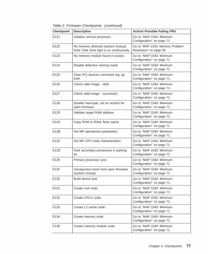
Table 2. Firmware Checkpoints. (continued)
Checkpoint Description Action/ Possible Failing FRU
E121 Initialize service processor Go to ″MAP 1540: MinimumConfiguration″ on page 71.
E122 No memory detected (system lockup)Note: Disk drive light is on continuously.
Go to “MAP 1240: Memory ProblemResolution” on page 39.
E123 No memory module found in socket. Go to ″MAP 1540: MinimumConfiguration″ on page 71.
E124 Disable defective memory bank Go to ″MAP 1540: MinimumConfiguration″ on page 71.
E125 Clear PCI devices command reg, goforth
Go to ″MAP 1540: MinimumConfiguration″ on page 71.
E126 Check valid image - start Go to ″MAP 1540: MinimumConfiguration″ on page 71.
E127 Check valid image - successful Go to ″MAP 1540: MinimumConfiguration″ on page 71.
E128 Disable interrupts, set int vectors foropen firmware.
Go to ″MAP 1540: MinimumConfiguration″ on page 71.
E129 Validate target RAM address Go to ″MAP 1540: MinimumConfiguration″ on page 71.
E12A Copy ROM to RAM, flush cache Go to ″MAP 1540: MinimumConfiguration″ on page 71
E12B Set MP operational parameters Go to ″MAP 1540: MinimumConfiguration″ on page 71
E12C Set MP CPU node characteristics Go to ″MAP 1540: MinimumConfiguration″ on page 71.
E12D Park secondary processors in parkinglot
Go to ″MAP 1540: MinimumConfiguration″ on page 71
E12E Primary processor sync Go to ″MAP 1540: MinimumConfiguration″ on page 71.
E12F Unexpected return from open firmware(system lockup)
Go to ″MAP 1540: MinimumConfiguration″ on page 71.
E130 Build device tree Go to ″MAP 1540: MinimumConfiguration″ on page 71.
E131 Create root node Go to ″MAP 1540: MinimumConfiguration″ on page 71.
E132 Create CPU’s node Go to ″MAP 1540: MinimumConfiguration″ on page 71.
E133 Create L2 cache node Go to ″MAP 1540: MinimumConfiguration″ on page 71.
E134 Create memory node Go to ″MAP 1540: MinimumConfiguration″ on page 71.
E135 Create memory module node Go to ″MAP 1540: MinimumConfiguration″ on page 71.
Chapter 4. Checkpoints 77

Table 2. Firmware Checkpoints. (continued)
Checkpoint Description Action/ Possible Failing FRU
E136 Test memory Go to ″MAP 1540: MinimumConfiguration″ on page 71.
E137 Create openprom node Go to ″MAP 1540: MinimumConfiguration″ on page 71.
E138 Create options node Go to ″MAP 1540: MinimumConfiguration″ on page 71.
E139 Create aliases node and system aliases Go to ″MAP 1540: MinimumConfiguration″ on page 71.
E13A Create packages node Go to ″MAP 1540: MinimumConfiguration″ on page 71.
E140 PReP- style load Go to ″MAP 1540: MinimumConfiguration″ on page 71.
E149 Create boot mgr node Go to ″MAP 1540: MinimumConfiguration″ on page 71.
E14C Create terminal-emulator node Go to ″MAP 1540: MinimumConfiguration″ page 71.
E14D Load boot image See “Boot Problems/Concerns” onpage 89.
E14E Create client interface node/directory Go to ″MAP 1540: MinimumConfiguration″ on page 71.
E14F NVRAM validation, config variable tokengeneration
Go to ″MAP 1540: MinimumConfiguration″ on page 71.
E150 Create host (primary) PCI controllernode
Go to ″MAP 1540: MinimumConfiguration″ on page 71.
E151 Probing primary PCI bus Go to Map 1540: MinimumConfiguration, “Step 1540-22” onpage 67.
If a network adapter or I/O board isreplaced, on page71.
E152 Probe for adapter FCODE, evaluate ifpresent
Go to “MAP 1540: MinimumConfiguration” on page 50.
E153 End adapter FCODE probe/evaluation Go to “MAP 1540: MinimumConfiguration” on page 50.
E154 Create PCI bridge node Go to “MAP 1540: MinimumConfiguration” on page 50.
E155 Probe PCI bridge secondary bus Go to “MAP 1540: MinimumConfiguration” on page 50.
E156 Create PCI Ethernet node Go to ″MAP 1540: MinimumConfiguration″ on page 71.
E15A Create 64 bit host (primary) PCIcontroller node
Go to ″MAP 1540: MinimumConfiguration″ on page 71.
E15B Transferring control to operating system(service mode boot)
See “Boot Problems/Concerns” onpage 89.
78 RS/6000 44P Series Model 270 Service Guide

Table 2. Firmware Checkpoints. (continued)
Checkpoint Description Action/ Possible Failing FRU
E15C Probe primary 64 bit PCI bus Go to ″MAP 1540: MinimumConfiguration″ on page 71.
E15D Create host PCI controller node Go to ″MAP 1540: MinimumConfiguration″ on page 71.
E15E Create MPIC node Go to ″MAP 1540: MinimumConfiguration″ on page 71
E15F Adapter VPD probe Go to ″MAP 1540: MinimumConfiguration″ on page 71.
E160 CPU node VPD creation Go to ″MAP 1540: MinimumConfiguration″ on page 71.
E161 Root node VPD creation Go to ″MAP 1540: MinimumConfiguration″ on page 71.
E162 Service processor node VPD creation Go to ″MAP 1540: MinimumConfiguration″ on page 71.
E164 Create PCI graphics node (P9) Go to ″MAP 1540: MinimumConfiguration″ on page 71.
E168 Create PCI graphics node (S3) Go to ″MAP 1540: MinimumConfiguration″ on page 71.
E171 Executing PCI-Delay function Go to ″MAP 1540: MinimumConfiguration″ on page 71.
E172 First pass PCI device probe Go to ″MAP 1540: MinimumConfiguration″ on page 71.
E174 Establish host connection Refer to “Boot Problems/Concerns” onpage 89 for general considerations.
E175 BootP request Refer to “Boot Problems/Concerns” onpage 89 for general considerations.1. Turn off then on, and retry the boot
operation.2. Verify the network connection
(network could be down).3. Have network administrator verify
the server configuration for thisclient.
E176 TFTP file transfer Refer to “Boot Problems/Concerns” onpage 89 for general considerations.1. Turn off then on, and retry the boot
operation.2. Verify the network connection
(network could be down).3. Have network administrator verify
the server configuration for thisclient.
Chapter 4. Checkpoints 79

Table 2. Firmware Checkpoints. (continued)
Checkpoint Description Action/ Possible Failing FRU
E177 Transfer failure due to TFTP errorcondition
Refer to “Boot Problems/Concerns” onpage 89 for general considerations.1. Turn off then on, and retry the boot
operation.2. Verify the network connection
(network could be down).3. Have network administrator verify
the server configuration for thisclient.
E178 Create PCI token ring node Go to ″MAP 1540: MinimumConfiguration″ on page 71.
E17B Processor frequency measurement 1. Replace battery, restore NVRAMdata (passwords, startup data)
2. Replace I/O board. (See note onpage 93).
E180 Service processor command setup Go to ″MAP 1540: MinimumConfiguration″ on page 71.
E183 Service processor post Go to ″MAP 1540: MinimumConfiguration″ on page 71.
E190 Create ISA node Go to ″MAP 1540: MinimumConfiguration″ on page 71.
E193 Initialize Super I/O. Go to ″MAP 1540: MinimumConfiguration″ on page 71.
E196 Probe ISA bus. Go to ″MAP 1540: MinimumConfiguration″ on page 71
E19B Create service processor node. Go to ″MAP 1540: MinimumConfiguration″ on page 71.
E19C Create tablet node. Go to ″MAP 1540: MinimumConfiguration″ on page 71.
E19D Create NVRAM node. Go to ″MAP 1540: MinimumConfiguration″ on page 71.
E19E Real time clock (RTC) creation andinitialization.
Refer to error code 28030xxx in“Firmware/POST Error Codes” onpage 94.
E19F Create EEPROM node. Go to ″MAP 1540: MinimumConfiguration″ on page 71.
E1AD See description of checkpoint E1DE. Go to ″MAP 1540: MinimumConfiguration″ on page 71.
E1B0 Create lpt node. 1. I/O board. (See note on page 93.)
2. Go to ″MAP 1540: MinimumConfiguration″ on page 71.
E1B1 Create serial node. Go to ″MAP 1540: MinimumConfiguration″ on page 71.
80 RS/6000 44P Series Model 270 Service Guide

Table 2. Firmware Checkpoints. (continued)
Checkpoint Description Action/ Possible Failing FRU
E1B2 Create audio node. 1. I/O board (See note on page 93.)
2. Go to ″MAP 1540: MinimumConfiguration″ on page 71.
E1B3 Create 8042 node. 1. I/O board (See note on page 93.)
2. Go to ″MAP 1540: MinimumConfiguration″ on page 71.
E1B6 Probe for (ISA) keyboard. 1. I/O board (See note on page 93.)
2. Go to ″MAP 1540: MinimumConfiguration″ on page 71.
E1BA Enable L2 cache. Go to ″MAP 1540: MinimumConfiguration″ on page 71.
E1BB Set cache parms for burst. Go to ″MAP 1540: MinimumConfiguration″ on page 71.
E1BC Set cache parms for 512 KB. Go to ″MAP 1540: MinimumConfiguration″ on page 71.
E1BD Probe for (ISA) mouse. 1. I/O board (See note on page 93.)
2. Go to ″MAP 1540: MinimumConfiguration″ on page 71.
E1BE Create operator panel node. Go to ″MAP 1540: MinimumConfiguration″ on page 71.
E1BF Create pwr-mgmt node. Go to ″MAP 1540: MinimumConfiguration″ on page 71.
E1C0 Create ISA Ethernet node Go to ″MAP 1540: MinimumConfiguration″ on page 71.
E1C5 Create ISA interrupt controller (pic)node.
1. I/O board (See note on page 93.)
2. Go to ″MAP 1540: MinimumConfiguration″ on page 71.
E1C6 Create DMA node. 1. I/O board (See notes on page 93.)
2. Go to ″MAP 1540: MinimumConfiguration″ on page 71.
E1D0 Create PCI SCSI node. Go to ″MAP 1540: MinimumConfiguration″ on page 71.
E1D3 Create SCSI block device node (SD). Go to ″MAP 1540: MinimumConfiguration″ on page 71.
E1D4 Create SCSI byte device node (ST). Go to ″MAP 1540: MinimumConfiguration″ on page 71.
E1DB Create floppy controller (FDC) node. 1. I/O board (See notes on page 93.)
2. Go to ″MAP 1540: MinimumConfiguration″ on page 71.
Chapter 4. Checkpoints 81

Table 2. Firmware Checkpoints. (continued)
Checkpoint Description Action/ Possible Failing FRU
E1DC Dynamic console selection. If a console is attached but nothing isdisplayed on it, follow the stepsassociated with ″All display problems″ inthe Entry MAP tables.
If selection screen(s) can be seen onthe terminals and the appropriate keyon the input device associated with thedesired display or terminal is pressedwithin 60 seconds, but there is noresponse to the keystroke:
1. If selecting the console with akeyboard attached to the system,replace the keyboard. If replacingthe keyboard does not fix theproblem, replace the I/O board. (Seenotes on page 93.)
2. If selecting the console with anASCII terminal, suspect the ASCIIterminal. Use the problemdetermination procedures for theterminal. Replace the I/O board ifthese procedures do not reveal aproblem. Note: Terminal settingsshould be set to:
v 9600 Baud
v No Parity
v 8 Data bits
v 1 Stop bit
E1DD Early processor exception 1. I/O board (See notes on page 93.)
2. Go to ″MAP 1540: MinimumConfiguration″ on page 71.
E1DE Alternating pattern of E1DE and E1ADis used to indicate a default catchcondition before the firmware″checkpoint″ word is available.
1. I/O board (See note on page 93.)2. Go to ″MAP 1540: Minimum
Configuration″ on page 71.
E1DF Create diskette drive (disk) node Go to ″MAP 1540: MinimumConfiguration″ on page 71.
E1E0 Program flash Go to ″MAP 1540: MinimumConfiguration″ on page 71.
E1E1 Flash update complete Go to ″MAP 1540: MinimumConfiguration″ on page 71.
E1E2 Initialize System I/O Go to ″MAP 1540: MinimumConfiguration″ on page 71.
E1E3 PReP boot image initialization. Go to ″MAP 1540: MinimumConfiguration″ on page 71.
82 RS/6000 44P Series Model 270 Service Guide

Table 2. Firmware Checkpoints. (continued)
Checkpoint Description Action/ Possible Failing FRU
E1E4 Initialize Super I/O with default values. Go to ″MAP 1540: MinimumConfiguration″ on page 71.
E1E5 XCOFF boot image initialization. Go to ″MAP 1540: MinimumConfiguration″ on page 71.
E1E6 Set up early memory allocation heap. Go to ″MAP 1540: MinimumConfiguration″ on page 71.
E1E7 PE boot image initialization. Go to ″MAP 1540: MinimumConfiguration″ on page 71.
E1E8 Initialize primary diskette drive (polledmode).
Go to ″MAP 1540: MinimumConfiguration″ on page 71
E1E9 ELF boot image initialization. Go to ″MAP 1540: MinimumConfiguration″ on page 71.
E1EA Firmware flash corrupted, load fromdiskette.
1. Ensure that the diskette installedcontains recovery image appropriatefor this system unit.
The System Management Servicesrecovery procedure for the flashEEPROM should be executed. See“Firmware Update” on page 205.
2. If the diskette is installed with thecorrect recovery image, thensuspect:
v Diskette
v Diskette drive
v Diskette cable
v I/O board (See notes on page93.)
3. Go to ″MAP 1540: MinimumConfiguration″ page 71.
Chapter 4. Checkpoints 83

Table 2. Firmware Checkpoints. (continued)
Checkpoint Description Action/ Possible Failing FRU
E1EB Verify flash EEPROM recovery image. 1. Ensure that the diskette installedcontains recovery image appropriatefor this system unit.
The System Management Servicesrecovery procedure for the flashEEPROM should be executed. See“Firmware Update” on page 205.
2. If the diskette is installed with thecorrect recovery image, thensuspect:
v Diskette drive
v Diskette cable
v I/O board (See notes on page93.)
3. Go to ″MAP 1540: MinimumConfiguration″ page 71.
E1EC Get recovery image entry point Go to ″MAP 1540: MinimumConfiguration″ on page 71.
E1ED Invalidate instruction cache Go to ″MAP 1540: MinimumConfiguration″ on page 71.
E1EE Jump to composite image Go to ″MAP 1540: MinimumConfiguration″ on page 71.
E1EF Erase flash Go to ″MAP 1540: MinimumConfiguration″ on page 71.
E1F0 Start O.B.E. Go to ″MAP 1540: MinimumConfiguration″ on page 71.
E1F1 Begin self-test sequence on bootdevice(s)
Go to ″MAP 1540: MinimumConfiguration″ on page 71.
E1F2 Power-on password prompt. Prompt should be visible on the systemconsole.
If a console is attached but nothing isdisplayed on it, go to the “Quick EntryMAP” on page 27 with the symptom ″Alldisplay problems.″
E1F3 Privileged-access password prompt. Prompt should be visible on the systemconsole.
If a console is attached but nothing isdisplayed on it, go to the “Quick EntryMAP” on page 27 with the symptom ″Alldisplay problems.″
E1F5 Build boot device list. Go to ″MAP 1540: MinimumConfiguration″ on page 71.
84 RS/6000 44P Series Model 270 Service Guide

Table 2. Firmware Checkpoints. (continued)
Checkpoint Description Action/ Possible Failing FRU
E1F6 Determine boot device sequence. Go to ″MAP 1540: MinimumConfiguration″ on page 71.
E1F7 No boot image located. Modify the boot sequence (also knownas boot list) to include devices that areknown to contain a copy of theoperating system. This can beaccomplished by using the systemmanagement services menus. Forexample, select a hard disk known tohave a copy of the operating system asthe first and only device in the bootsequence (boot list) and attempt to bootagain.
E1FB Scan SCSI bus for attached devices. Go to ″MAP 1540: MinimumConfiguration″ on page 71.
E1FD Default catch The operator panel will alternatebetween the code E1FD and anotherExxx code, where Exxx is the point atwhich the error occurred. If the Exxx isnot listed in this table, go to “MAP 1540:Minimum Configuration” on page 50.
E201 Setup PHB BARC addresses. 1. Replace the I/O board (See note onpage 93.)
2. Go to ″MAP 1540: MinimumConfiguration″ on page 71.
E202 Initialize PHB registers and PHB’s PCIconfiguration registers.
1. Replace the I/O board (See note onpage 93.)
2. Go to ″MAP 1540: MinimumConfiguration″ on page 71.
E203 Look for PCI to ISA bridge. 1. Replace the I/O board (See note onpage 93.)
2. Go to ″MAP 1540: MinimumConfiguration″ on page 71.
E204 Setup ISA bridge, PCI config. registersand initialize
1. Replace the I/O board (See note onpage 93.)
2. Go to ″MAP 1540: MinimumConfiguration″ on page 71.
E206 Check for 50MHz device on PCI bus inslots 1P and 2P.
1. Replace the I/O board (See note onpage 93.)
2. I/O adapter in PCI slot 1P or 2P.3. Go to ″MAP 1540: Minimum
Configuration″ on page 71.
Chapter 4. Checkpoints 85

Table 2. Firmware Checkpoints. (continued)
Checkpoint Description Action/ Possible Failing FRU
E207 Setup data gather mode and 64/32-bitmode on PCG.
1. Replace the I/O board (See note onpage 93.)
2. Go to ″MAP 1540: MinimumConfiguration″ on page 71.
E208 Assign bus number on PCG. 1. Replace the I/O board (See note onpage 93.)
2. Go to ″MAP 1540: MinimumConfiguration″ on page 71.
E209 Assign PCI I/O addresses on PCI. 1. Replace the I/O board (See note onpage 93.)
2. Go to ″MAP 1540: MinimumConfiguration″ on page 71.
E20A Assign PCI I/O addresses on PCG 1. Replace the I/O board. (See note onpage 93.)
2. Go to ″MAP 1540: MinimumConfiguration″ on page 71.
E20B Check MCERs stuck at fault. 1. Replace the system board.2. If the problem persists, go to “MAP
1540: Minimum Configuration” onpage 50.
E20C Testing L2 cache. 1. Replace the processor card.
2. Go to ″MAP 1540: MinimumConfiguration″ on page 71.
E210 Processors L1 data cache array testfails. System hangs.
1. Replace I/O board.
2. Go to ″MAP 1540: MinimumConfiguration″ on page 71.
E211 IPL ROS CRC checking. 1. Replace the I/O board. (See note onpage 93.)
2. Go to ″MAP 1540: MinimumConfiguration″ on page 71.
E212 Processor POST. 1. Replace the processor card.
2. Go to ″MAP 1540: MinimumConfiguration″ on page 71.
E213 Initial memory configuration. Go to “MAP 1240: Memory ProblemResolution” on page 39.
E214, E218 Memory test. Go to “MAP 1240: Memory ProblemResolution” on page 39.
E216 Copy ROS into RAM. Setup translationand C environment.
1. Replace the memory card .
2. Go to ″MAP 1540: MinimumConfiguration″ on page 71.
86 RS/6000 44P Series Model 270 Service Guide

Table 2. Firmware Checkpoints. (continued)
Checkpoint Description Action/ Possible Failing FRU
E21A System has good memory Go to ″MAP 1540: MinimumConfiguration″ on page 71.
E220 Final memory configuration. Go to “MAP 1240: Memory ProblemResolution” on page 39.
E240 Setup Winbond ISA bridge. 1. Replace I/O board. (See notes onpage 93.)
2. Go to ″MAP 1540: MinimumConfiguration″ on page 71.
E241 Reset PCI Bus. 1. Replace I/O board. (See notes onpage 93.)
2. Go to ″MAP 1540: MinimumConfiguration″ on page 71.
E242 Initialize ISA DMA channel. 1. Replace I/O board. (See notes onpage 93.)
2. Go to ″MAP 1540: MinimumConfiguration″ on page 71.
E243 Setup Grackle configuration registers. 1. Replace I/O board. (See note onpage 93.)
2. Go to ″MAP 1540: MinimumConfiguration″ on page 71.
E244 Enable system speaker and send abeep.
1. Replace I/O board. (See note onpage 93.)
2. Go to ″MAP 1540: MinimumConfiguration″ on page 71.
E246 System firmware corrupted, takerecovery path.
1. Replace I/O board. (See note onpage 93.)
2. Go to ″MAP 1540: MinimumConfiguration″ on page 71.
E247 Capture DIMM SPDs into NVRAM. 1. Replace I/O board. (See note onpage 93.)
2. Go to ″MAP 1540: MinimumConfiguration″ on page 71.
E249 Enter recover path’s main code. 1. Replace I/O board. (See note onpage 93.)
2. Go to ″MAP 1540: MinimumConfiguration″ on page 71.
E24C L2 cache array test fails. System hangs. 1. Replace I/O board. (See note onpage 93.)
2. Go to ″MAP 1540: MinimumConfiguration″ on page 71.
Chapter 4. Checkpoints 87

Table 2. Firmware Checkpoints. (continued)
Checkpoint Description Action/ Possible Failing FRU
E24D L2 cache array test fails. System hangs. 1. Replace I/O board. (See note onpage 93.)
2. Go to ″MAP 1540: MinimumConfiguration″ on page 71.
E297 Start firmware softload path execution. Go to ″MAP 1540: MinimumConfiguration″ on page 71.
E298 Start firmware recovery path execution. Go to ″MAP 1540: MinimumConfiguration″ on page 71.
E299 Start C code execution. Go to ″MAP 1540: MinimumConfiguration″ on page 71.
E3xx Memory test See “MAP 1240: Memory ProblemResolution” on page 39.
E440 Validate NVRAM, initialize partitions asneeded.
1. Verify that the system and serviceprocessor firmware levels are at thecurrent release levels; update asnecessary.
2. Replace the I/O board. (See note onpage 93.)
3. Go to ″MAP 1540: MinimumConfiguration″ on page 71.
E441 Generate /options node NVRAMconfiguration variable properties.
1. Verify that the system and serviceprocessor firmware levels are at thecurrent release levels, update asnecessary.
2. Replace the I/O board. (See note onpage 93.)
3. Go to ″MAP 1540: MinimumConfiguration″ on page 71.
E442 Validate NVRAM partitions. 1. Verify that the system and serviceprocessor firmware levels are at thecurrent release levels; update asnecessary.
2. Replace the I/O board. (See note onpage 93.)
3. Go to ″MAP 1540: MinimumConfiguration″ on page 71.
E443 Generate NVRAM configuration variabledictionary words.
1. Suspect a system firmware problemif this problem persists. Verify thatthe system firmware is at the currentrelease level; update as necessary.
2. Go to ″MAP 1540: MinimumConfiguration″ on page 71.
E600 SSA PCI adapter open firmware has runsuccessfully.
1. Replace the adapter.2. Go to ″MAP 1540: Minimum
Configuration″ on page 71.
88 RS/6000 44P Series Model 270 Service Guide

Table 2. Firmware Checkpoints. (continued)
Checkpoint Description Action/ Possible Failing FRU
E601 SSA PCI adapter BIST has been startedbut failed to complete after 4 secs.
1. Replace the adapter.2. Go to ″MAP 1540: Minimum
Configuration″ on page 71.
E602 SSA PCI adapter open firmware hasstarted.
1. Replace the adapter.2. Go to ″MAP 1540: Minimum
Configuration″ on page 71..
E603 SSA PCI adapter BIST has completedwith an error.
1. Replace the adapter.2. Go to ″MAP 1540: Minimum
Configuration″ on page 71.
E604 SSA PCI adapter BIST and subsequentPOSTs have completed successfully
1. Replace the adapter.2. Go to ″MAP 1540: Minimum
Configuration″ on page 71.
E605 SSA PCI adapter BIST has completedsuccessfully, but the subsequent POSTshave failed.
1. Replace the adapter.2. Go to ″MAP 1540: Minimum
Configuration″ on page 71.
E60E SSA PCI adapter open firmware aboutto exit (no stack corruption).
1. Replace the adapter.2. Go to ″MAP 1540: Minimum
Configuration″ on page 71.
E60F SSA PCI adapter open firmware has rununsuccessfully.
1. Replace the adapter.2. Go to ″MAP 1540: Minimum
Configuration″ on page 71.
E6FF SSA PCI adapter open firmware aboutto exit (with stack corruption)
1. Replace the adapter.2. Go to ″MAP 1540: Minimum
Configuration″ on page 71
Boot Problems/ConcernsDepending on the boot device, a checkpoint may be displayed on the operator panel foran extended period of time while the boot image is retrieved from the device. This isparticularly true for tape and network boot attempts. If booting from CD-ROM or tape,watch for activity on the drive’s LED indicator. A blinking LED indicates that the loadingof either the boot image or additional information required by the operating systembeing booted is still in progress. If the checkpoint is displayed for an extended period oftime and the drive LED is not indicating any activity, there might be a problem loadingthe boot image from the device.
Note: For network boot attempts, if the system is not connected to an active network orif the target server is inaccessible (which can also result from incorrect IPparameters being supplied), the system will still attempt to boot. Becausetime-out durations are necessarily long to accommodate retries, the system mayappear to be hung.
This procedure assumes that a CD-ROM drive is connected to internal SCSI connectorJ7 and a diagnostics CD-ROM is available.
Chapter 4. Checkpoints 89

Step 1Restart the system and access the firmware SMS Main Menu. Select Multiboot .
1. Check if the intended boot device is correctly specified in the boot sequence.
2. If the intended boot device is not correctly identified in the boot sequence, add it tothe boot sequence using the SMS menus, (if the intended boot device cannot beadded to the boot sequence, go to “Step 3”.)
3. If attempting to boot from the network, go to “Step 2”.
4. If attempting to boot from a disk drive or CD-ROM, go to “Step 3”.
Step 2If you are attempting to boot from the network:
1. Verify that IP parameters are correct.
2. Attempt to ″ping″ the target server using the SMS Ping utility. If the ping is notsuccessful, have the network administrator verify the server configuration for thisclient.
3. Check with the network administrator to ensure that the network is up.
4. Check the network cabling to the adapter.
5. Turn the power off, then on and retry the boot operation.
Step 3Try to boot and run standalone diagnostics against the system, particularly against theintended boot device.
1. If the intended boot device is not listed in the ″NEW RESOURCE″ list, go to ″MAP0290: Missing Resource Problem Resolution″ in the RS/6000 Diagnostic Informationfor Multiple Bus Systems.
2. If an SRN, not an 8-digit error code, is reported, go to the RS/6000 DiagnosticInformation for Multiple Bus Systems.
3. If the diagnostics are successful, it may be necessary to perform an operatingsystem-specific recovery process, or reinstall the operating system.
4. If you are unable to load standalone diagnostics, do the following:
a. Verify correct SCSI bus termination.
b. Check SCSI cabling.
c. It is possible that another attached SCSI device is causing the problem. Do thefollowing:
1) Disconnect the signal and power cables from the disk drive cage backplane.
2) Disconnect the disk drive(s) in the disk drive cage from the backplane.
3) Disconnect the signal and power cables from any other SCSI devicesattached to the SCSI adapter that the CD-ROM drive is attached to.
4) Try to boot the standalone diagnostics again.
5) If you are still unable to load standalone diagnostics go to “Step 4” onpage 91.
6) If standalone diagnostics load, one of the disconnected devices is causingthe problem. Reconnect the devices one at a time and retry the bootoperation until the problem recurs and replace the device that caused theproblem. (If the problem appears to be one of the disk drives in the disk
90 RS/6000 44P Series Model 270 Service Guide

drive cage, be aware it could be either the disk drive or the backplane.) Goto "MAP 410: Repair Checkout" in the RS/6000 Diagnostic Information forMultiple Bus Systems.
Step 4It is possible that another installed adapter is causing the problem. Do the following:
1. Remove all installed adapters except the one the CD-ROM drive is attached to andthe one used for the console.
2. Try to boot the standalone diagnostics again.
3. If you are unable to load standalone diagnostics, go to “Step 5”.
4. If standalone diagnostics load, reinstall adapters (and attached devices asapplicable) one at a time and retry the boot operation until the problem recurs. Thenreplace the adapter or device that caused the problem. (The system board can alsocause the device or adapter to fail.) Go to "MAP 410: Repair Checkout" in theRS/6000 Diagnostic Information for Multiple Bus Systems.
Step 5The CD-ROM drive, SCSI cable, SCSI adapter, graphics adapter, or the system boardis most likely defective. A SCSI terminal attached to the serial port also can be used todetermine if the graphics adapter is causing the problem. This is done by removing thegraphics adapter, attaching an SCSI terminal to the serial port, and retrying standalonediagnostics. If the standalone diagnostics load, replace the graphics adapter.
1. Replace the CD-ROM drive.
2. Replace the SCSI cable.
3. If the CD-ROM drive is attached to a SCSI adapter rather than the integrated SCSIon the system board, replace the SCSI adapter.
4. Replace the system board.
5. If you replaced the indicated FRUs or performed an action and the problem is stillnot corrected, or the above descriptions did not address your particular situation, goto “MAP 1540: Minimum Configuration” on page 50.
6. Go to "MAP 410: Repair Checkout" in RS/6000 Diagnostic Information for MultipleBus Systems.
Chapter 4. Checkpoints 91

92 RS/6000 44P Series Model 270 Service Guide

Chapter 5. Error Code to FRU Index
The Error Code to FRU Index lists error symptoms and possible causes. The mostlikely cause is listed first. Use this index to help you decide which FRUs to replacewhen you are servicing the system.
Considerations for Using this ChapterIf you replace FRUs or perform an action, and the problem is still not corrected, go to“MAP 1540: Minimum Configuration” on page 50, unless otherwise indicated in thetables.
If you replace FRUs and the problem is corrected, go to "MAP 410: Repair Checkout" inthe RS/6000 Diagnostic Information for Multiple Bus Systems.
Performing Slow BootTo fully analyze all of the available information, perform the following steps before doinga hardware repair or replacement, especially if the error is related to the CPU ormemory.
1. Record the 8-character error code (and location code if present) displayed in theoperator panel, or that was reported by the customer.
2. Do a slow-mode boot in service mode. This can be specified using the SystemPower Control Menu on the service processor main menu. (A fast-mode boot skipsmuch of the built-in diagnostic testing.) A slow-mode boot may yield a new8-character error code on the operator panel and new errors in the serviceprocessor error log. If a new error code is reported, use it in subsequent steps tocontinue problem analysis.
General ConsiderationsIf the codes in the following tables indicate a device that is present more than once inthe system unit, a location code is needed to specify which device generated the error.Go to “Step 1020-4” on page 38 to display the System Management Services error logand obtain a location code. Location code descriptions can be found under “LocationCodes” on page 9.
After you have obtained the location code, see “Chapter 10. Parts Information” onpage 267 for the part number.
Notes:
1. If more than eight digits are displayed in the operator panel, use only the first eightdigits to find the error in the tables. The digits that display beyond the first eightdigits are location codes that can assist you in diagnosing the problem. See“Location Codes” on page 9.
2. Licensed programs frequently rely on network configuration and system informationstored in the VPD module on the operator panel control assembly. If the MAPsindicate that the operator panel control assembly should be replaced, swap the VPDmodule from the old operator panel to the new one. If the existing VPD module
93

must be replaced, call technical support for recovery instructions. If recovery is notpossible, notify the system owner that new keys for licensed programs may berequired.
3. If a network adapter or the I/O board is replaced, the network administrator must benotified so that the client IP addresses used by the server can be changed. Inaddition, the operating system configuration of the network controller might need tobe changed in order to enable system startup. Also check to ensure that any clientor server that addresses this system is updated.
4. For service processor menus, see “Chapter 7. Using the Service Processor” onpage 147.
Firmware/POST Error Codes
Table 3. Firmware Error Codes.
Error Code Description Action / Possible Failing FRU
20A80000 Insufficient information to boot. Verify the IP address.
20A80001 Client IP address is already in use byother network device.
Change IP address.
20A80002 Cannot get gateway IP address. Go to table using code E174 “FirmwareCheckpoints” on page 75.
20A80003 Cannot get server hardware address. Go to table using code E174 “FirmwareCheckpoints” on page 75.
20A80004 Bootp failed. 1. Refer to “Boot Problems/Concerns”on page 89 for general
considerations.2. Turn off then on, and retry the boot
operation.3. Verify boot list by using the firmware
SMS multiboot menus.4. Verify the network connection
(network could be down).5. Have network administrator verify
the server configuration for thisclient.
20A80005 File transmission (FTP) failed. Check network connection, try again.
20A80006 Image too big. Ran out of availablefirmware memory resources loadingboot image.
Verify boot server configuration.
20D0000F Self-test failed on device, noerror/location code information available.
Check the System ManagementServices error log (described in “Step1020-4” on page 38) for this error code.The location code (if present) in theerror log entry should identify thelocation of the failing device.
20D00010 Self-test failed on device, cannot locatepackage.
Contact your service supportrepresentative for assistance.
94 RS/6000 44P Series Model 270 Service Guide

Table 3. Firmware Error Codes. (continued)
Error Code Description Action / Possible Failing FRU
20D00011 Instantiate RTAS failed. Contact your service supportrepresentative for assistance.
20E00000 Power-on password entry error. The password has been enteredincorrectly.
Retry installing the password.
20E00001 Privileged-access password entry error. The password has been enteredincorrectly.
Retry installing the password.
20E00002 Privileged-access password jumper notenabled.
The privileged-access password jumperis not in the correct position forpassword initial entry.
Consult the system’s user’s guide forjumper location and position.
20E00003 Power-on password must be set forunattended mode.
Unattended mode requires the setting ofthe power-on password before it isenabled.
20E00004 Battery drained or needs replacement. 1. Replace battery.2. Replace I/O board. (See note on
page 93.)
20E00005 EEPROM locked 1. Turn off, turn on system unit.2. Replace I/O board. (See note on
page 93.)
20E00008 CMOS reinitialized due to corruption. 1. Replace battery, restore NVRAMdata (passwords, startup data).
2. Replace I/O board. (See note onpage 93.)
20E00009 Invalid password entered - systemlocked.
The password has been enteredincorrectly 3 times.
Turn off, then turn on the system unit,then enter the password correctly.
20E0000C Failed to open RTC device tree node 1. Turn off, turn on system unit.2. Replace I/O board. (See note on
page 93.)
20E00017 Cold boot needed for password entry. Turn off, turn on system unit.
20EE0003 IP parameter requires 3 dots ″.″ Enter valid IP parameter.
Example: 000.000.000.000
20EE0004 Invalid IP parameter. Enter valid (numeric) IP parameter.
Example: 000.000.000.000
Chapter 5. Error Code to FRU Index 95

Table 3. Firmware Error Codes. (continued)
Error Code Description Action / Possible Failing FRU
20EE0005 Invalid IP parameter (>255) Enter valid (numeric) IP parameter inthe range of 0 to 255.
Example: 255.192.002.000
20EE0006 No SCSI controllers present The I/O board should always have (atleast) 2 integrated PCI SCSI controllers;replace the I/O board. (See note onpage 93.)
20EE0007 Keyboard not found 1. Plug in keyboard.2. Replace I/O board. (See note on
page 93.)
20EE0008 No configurable adapters found in thesystem.
This warning occurs when the selectedSMS function cannot locate anydevices/adapters supported by thefunction. If a supported device isinstalled:
1. Replace the device or adapter.
2. Replace I/O board. (See note onpage 93.)
20EE0009 Unable to communicate with the serviceprocessor.
1. Replace I/O board. (See note onpage93
2. Replace system board.
3. Go to ″MAP 1540: MinimumConfiguration″ on page 71.
96 RS/6000 44P Series Model 270 Service Guide

Table 3. Firmware Error Codes. (continued)
Error Code Description Action / Possible Failing FRU
20EE000A Pointer to the operating system found innon-volatile storage.
Values normally found in non-volatilestorage that point to the location of anoperating system were not found. Thiscan happen for either of two reasons:
1. Your installed operating system doesnot support storing the values.
2. Some event occurred that causedthe system to lose non-volatilestorage information (drainage orreplacement of the battery).
If you are running AIX, this informationcan be reconstructed by running thebootlist command, specifying thedevice that the operating system isinstalled on. Refer to your AIXdocumentation for the exact syntax andusage of the bootlist command.
To boot the operating system so that theabove-mentioned values can bereconstructed, power down the systemand power it back up again. This shouldcause the system to look for theoperating system in the devicescontained in the custom boot list or inthe default boot list, depending on thecondition of the system. If this is notsuccessful, use the systemmanagement services menus to modifythe boot sequence (also known as bootlist) to include devices that are known tocontain a copy of the operating system.For example, select a hard disk knownto have a copy of the operating systemas the first and only device in the bootsequence (boot list) and attempt to bootagain.
20EE000B The system was not able to find anoperating system on the boot list thatwas attempted.
Use the system management servicesmenus to modify the boot sequence(also known as boot list) to includedevices that are known to contain acopy of the operating system. Forexample, select a hard disk known tohave a copy of the operating system asthe first and only device in the bootsequence (boot list) and attempt to bootagain.
Chapter 5. Error Code to FRU Index 97

Table 3. Firmware Error Codes. (continued)
Error Code Description Action / Possible Failing FRU
21A00xxx SCSI DASD device errorsNotes:
1. Before replacing any systemcomponents:a. Ensure that the controller and
each device on the SCSI bus isassigned a unique SCSI ID.
b. Ensure SCSI bus is properlyterminated.
c. Ensure SCSI signal and powercables are securely connectedand not damaged.
2. The location code information isrequired to identify the ID of SCSIdevice failures as well as to indicatethe location of the controller towhich the device is attached.
3. Check below for the xxx value, thexxx can stand for anything like 001,002, 003 and so on. Ensure that thesuspected SCSI device is checkedout completely.
21A00001 Test unit ready failed - hardware error. Refer to the notes in error code21A00xxx.1. Replace the SCSI device.2. Replace the SCSI cable.3. Replace the SCSI controller.
21A00002 Test unit ready failed - sense dataavailable.
Refer to the notes in error code21A00xxx.1. Replace the media (removable
media devices).2. Replace the SCSI device.
21A00003 Send diagnostic failed. 1. Refer to the notes in error code21A00xxx.
2. Replace the SCSI device.
21A00004 Send diagnostic failed - DevOflcommand.
1. Refer to the notes in error code21A00xxx.
2. Replace the SCSI device.
21E00xxx SCSI tape Refer to 21A00xxx for a description andrepair action for the xxx value.
21ED0xxx SCSI changer. Refer to 21A00xxx for a description andrepair action for the xxx value.
21EE0xxx Other SCSI device type. Refer to 21A00xxx for a description andrepair action for the xxx value.
21F00xxx SCSI CD-ROM. Refer to 21A00xxx for a description andrepair action for the xxx value.
98 RS/6000 44P Series Model 270 Service Guide

Table 3. Firmware Error Codes. (continued)
Error Code Description Action / Possible Failing FRU
21F20xxx SCSI read/write optical. Refer to 21A00xxx for a description andrepair action for the xxx value.
22000001 Internal wrap test failed. Replace adapter.
22001001 Internal wrap test failed. Replace adapter.
22002001 Adapter failed to complete hardwareinitialization.
Replace adapter.
22010001 Adapter failed to complete hardwareinitialization.
Replace adapter.
22011001 Adapter failed to complete hardwareinitialization.
Replace adapter.
25000000 Memory controller failed. Replace the system board.
25010xxx Flash update problem
25010000 No diskette in drive. Insert diskette containing firmwareimage.
25010001 Diskette seek error. 1. Retry function.2. Replace diskette drive.3. Replace diskette cable.4. Replace I/O board. (See note on
page 93.)
25010002 Diskette in drive does not contain an*.IMG file.
Insert diskette with firmware update file.
25010003 Cannot open OPENPROM package. Replace I/O board. (See note on page93.)
25010004 Cannot find OPENPROM node. Replace I/O board. (See note on page93.)
25010006 System id does not match imagesystem id.
Make sure correct firmware updatediskette is being used with this system.
25010007 Image has bad CRC. Replace firmware update diskette.
25010008 Flash is write-protected, updatecancelled.
1. Turn off, turn on system unit andretry.
2. Replace I/O board. (See note onpage 93.)
25010009 Flash module is unsupported or notrecognized.
Make sure correct firmware updatediskette is being used with this system.
2501000A Flash write-protected. 1. Turn off, turn on system unit, retry.2. Replace I/O board. (See note on
page 93.)
2501000C Failed write to flash memory. 1. Turn off, turn on system unit, retry.2. Replace I/O board. (See note on
page 93.)
Chapter 5. Error Code to FRU Index 99

Table 3. Firmware Error Codes. (continued)
Error Code Description Action / Possible Failing FRU
25A0xxx0 L2 cache controller problem. 1. Replace the processor card.2. Replace the system board.
See error code 2B2xxx22 for xxxdefinitions.
25A0xxx1 L2 cache controller problem. 1. Replace the processor card.2. Replace the system board.
See error code 2B2xxx22 for xxxdefinitions.
25A1xxxy L2 SRAM failure Replace the processor card. See errorcode 2B2xxx22 for xxx definitions.
25A80xxx NVRAM problems 1. Errors reported against NVRAM canbe caused by low battery voltageand (more rarely) power outagesthat occur during normal systemusage. With the exception of the25A80000 error, these errors arewarnings that the NVRAM datacontent had to be re-established anddo not require any FRU replacementunless the error is persistent. Whenone of these errors occurs, anysystem customization (for exampleboot device list) information hasbeen lost; the system may need tobe reconfigured.
2. If the error is persistent, replace thebattery.
3. If the error is persistent after batteryreplacement, or the error code is25A80000, replace the I/O board.(See note on page 93.)
25A80000 Initialization failed, device test failed. Refer to Action under error code25A80xxx.
25A80001 Init-nvram invoked, all of NVRAMinitialized.
Refer to Action under error code25A80xxx.
25A80002 Init-nvram invoked, some data partitionsmay have been preserved.
Refer to Action under error code25A80xxx.
25A80011 Data corruption detected, all of NVRAMinitialized.
Refer to Action under error code25A80xxx.
25A80012 Data corruption detected; some datapartitions may have been preserved.
Refer to Action under error code25A80xxx.
100 RS/6000 44P Series Model 270 Service Guide

Table 3. Firmware Error Codes. (continued)
Error Code Description Action / Possible Failing FRU
25A80100 NVRAM data validation check failed. Turn off, turn on system unit and retrythe operation before replacing anysystem component. Refer to Actionunder error code 25A80xxx.
25A80201 Unable to expand target partition whilesaving configuration variable.
Refer to Action under error code25A80xxx.
25A80202 Unable to expand target partition whilewriting error log entry.
Refer to Action under error code25A80xxx.
25A80203 Unable to expand target partition whilewriting VPD data.
Refer to Action under error code25A80xxx.
25A80210 Setenv/$Setenv parameter error - namecontains a null character.
Refer to Action under error code25A80xxx.
25A80211 Setenv/$Setenv parameter error - valuecontains a null character.
Refer to Action under error code25A80xxx.
Chapter 5. Error Code to FRU Index 101

Table 3. Firmware Error Codes. (continued)
Error Code Description Action / Possible Failing FRU
25A80998 NVRAMRC script evaluation error -command line execution error
Execution of a command line within theNVRAM configuration variable″NVRAMRC″ (script) resulted in a″throw″ being executed. This script canbe modified by the system firmwareSMS utilities, the operating system, PCIadapter ROM code or utility, or anoperator (via the open firmware scriptediting command ″nvedit″). It may notbe possible to resolve the problemwithout a detailed analysis of theNVRAM script, current systemconfiguration, and device tree contents.
1. The problem can be caused by aSCSI adapter, whose SCSI bus IDhas been changed from the defaultsetting, no longer appearing in thesystem. This can be caused eitherby removing adapter, or problemwith a SCSI adapter.v Select the SCSI ID utility from the
SMS menu(s).
a. Verify the list of SCSIcontrollers/adapters. If the listis not correct, suspect aproblem with he adapter(s)installed but not listed.
b. Select the option to SAVE theconfiguration information.
c. Restart the system.v If the problem persists, boot the
operating system and verify theSCSI bus IDs of anyinstalled/available SCSIcontrollers (change asnecessary), and restart thesystem.
2. Contact your service supportrepresentative for further assistance.
25A80999 NVRAMRC script evaluation error -stack unbalanced on completion.
This is a firmware debug environmenterror. There is no user action or FRUreplacement.
102 RS/6000 44P Series Model 270 Service Guide

Table 3. Firmware Error Codes. (continued)
Error Code Description Action / Possible Failing FRU
Memory Errors
Use the location code obtained from the SMS error log utility (described in “Step 1020-4” onpage 38) to identify which memory module (or memory module pair) the error is reported against.
Memory error codes are in the form 25Byyxxx where yy indicates memory module PD-bits andxxx indicates the last 3 digits of the error code.
See “Memory Problem Determination Bits” on page 141 for information on how to interpret PDbits.
25B00001 No memory DIMMs detected 1. Reseat any installed memory card(s)and retry
2. Reseat any installed memorymodules on the installed memorycards and retry.
3. Replace memory card(s).
4. Replace system board.
25B00002 Multiple memory modules failed memorytest.
1. Reseat any installed memory card(s)and retry
2. Reseat any installed memorymodules on the installed memorycards and retry.
3. Replace memory card(s).
4. Replace system board.
25Cyy001 Memory module is not supported. Replace unsupported memory module.Note:
A memory module must be replacedwith a supported type ofmemorymodule. If an unsupported memorymodule is replaced by the sameunsupported type, the error remains.
There may be two memorymodule-related memory errors reportedto indicate a memory module pair. Oneof the two indicated memory modulesmay be good. When replacing memory,replace one memory module at a time,not both.
See “Memory Problem DeterminationBits” on page 141 for definition of ″yy″.
Chapter 5. Error Code to FRU Index 103

Table 3. Firmware Error Codes. (continued)
Error Code Description Action / Possible Failing FRU
25Cyy002 Memory module fails memory test. 1. Replace memory module.
2. Replace memory card.
3. Replace the system board.
See “Memory ProblemDetermination Bits” on page 141 fordefinition of ″yy″.
25Cyy003 PD bits are mismatched or missing onememory module.
1. Make sure both memory modules inthe pair are the same type.
2. Replace system board.
See “Memory ProblemDetermination Bits” on page 141 fordefinition of ″yy″.
25Cyy004 Memory modules are disabled. Remove this unused memory module.
See “Memory Problem DeterminationBits” on page 141 for definition of ″yy″.
25Cyy005 Memory module failed address test. 1. Replace memory module.
2. Replace memory card.
3. Replace system board.
4. Replace processor card.
See “Memory ProblemDetermination Bits” on page 141 fordefinition of ″yy″.
25Cyy006 Memory module failed inter-extent test. 1. Replace system board.2. Replace processor card.
See “Memory ProblemDetermination Bits” on page 141 fordefinition of ″yy″.
25Cyy007 Memory module failed extent accesstest.
1. Replace system board.2. Replace processor card.
See “Memory Problem DeterminationBits” on page 141 for definition of ″yy″.
25Cyy008 Memory module has been deconfigured. Replace memory module.
See “Memory Problem DeterminationBits” on page 141 for definition of ″yy″.
104 RS/6000 44P Series Model 270 Service Guide

Table 3. Firmware Error Codes. (continued)
Error Code Description Action / Possible Failing FRU
26020001 Invalid PCI adapter vendor ID. 1. Move adapter to another slot(behind a different PCI bridge).
2. Check for available firmwareupdates for adapter. Apply update ifavailable.
3. Run AIX diagnostics on adapter.Replace if indicated.
4. Replace adapter.
5. Check for system firmware updates.Apply if update available.
6. Replace power supply.
7. Replace I/O board. (See note onpage 93.)
26020002 Invalid PCI adapter device ID. 1. Move adapter to another slot(behind a different PCI bridge).
2. Check for available firmwareupdates for adapter. Apply update ifavailable.
3. Run AIX diagnostics on adapter.Replace if indicated.
4. Replace adapter.
5. Check for system firmware updates.Apply if update available.
6. Replace power supply.
7. Replace I/O board. (See note onpage 93.)
26020003 Invalid or unrecognized PCI adapterclass code.
1. Move adapter to another slot(behind a different PCI bridge).
2. Check for available firmwareupdates for adapter. Apply update ifavailable.
3. Run AIX diagnostics on adapter.Replace if indicated.
4. Replace adapter.
5. Check for system firmware updates.Apply if update available.
6. Replace power supply.
7. Replace I/O board. (See note onpage 93.)
Chapter 5. Error Code to FRU Index 105

Table 3. Firmware Error Codes. (continued)
Error Code Description Action / Possible Failing FRU
26020007 Failed to allocate bus resources to PCIadapter.
1. Move adapter to another slot(behind a different PCI bridge).
2. Check for available firmwareupdates for adapter. Apply update ifavailable.
3. Run AIX diagnostics on adapter.Replace if indicated.
4. Replace adapter.
5. Check for system firmware updates.Apply if update available.
6. Replace power supply.
7. Replace I/O board. (See note onpage 93.)
26800Cxx Machine check occurred. If the location code shown on theoperator panel identifies a card slot:
1. Replace the adapter in the slotidentified.
2. Replace the I/O board (See note onpage 93.)
If the location code shown does notidentify a card slot, or if there is nolocation code, replace the I/O board.(See note on page 93.)
26800Dxx Machine check occurred, unable toisolate to single device
″xx″ indicates the PCI bus number withthe error
1. Attempt to reboot the system inservice mode; this preserves the AIXerror log. If the reboot is successful,run diagnostics in problemdetermination mode to determinethe cause of failure. Otherwisecontinue.
2. Refer to the ″Bus SRN to FRUReference Table″ page 123, usingPCI Bus ″xx″ for isolation of thefailing device.
106 RS/6000 44P Series Model 270 Service Guide

Table 3. Firmware Error Codes. (continued)
Error Code Description Action / Possible Failing FRU
28030xxx RTC errors 1. Errors reported against the real timeclock (RTC) can be caused by lowbattery voltage and (more rarely)power outages that occur duringnormal system usage. These errorsare warnings that the RTC datacontent had to be re-established anddo not require any FRU replacementunless the error is persistent. Whenone of these errors occurs, thepower-on password and time anddate information has been lost.v To set/restore a power-on
password, use the SMS utility.v To set/restore the time and date,
use the operating system facility.
2. If the error is persistent, replace thebattery.
3. If the error is persistent after batteryreplacement, replace the I/O board.(See note on page 93.)
28030001 RTC initialization required-RTC notupdating, corrected.
Refer to Action under error code28030xxx.
28030002 Bad time/date values 1. Set the time and date.2. Refer to Action under error code
28030xxx.
28030003 RTC initialization required-RTC notupdating, not corrected.
Replace I/O board. (See note on page93.
28030004 RTC operating mode parameterschanged (such as data format)
1. Set/restore the time and date2. Refer to RTC problem resolution
above if problem persists.
28030005 RTC battery error 1. Replace the battery2. Refer to RTC problem resolution
above if problem persists.
Password, time, and date must bereset.
28030006 Processor frequency measurement error 1. Verify that the current level of thesystem firmware is installed.
2. Replace the processor card3. Replace I/O planar
Replacing the battery does notcorrect this error condition.
29000002 Keyboard/mouse controller failedself-test.
Replace the I/O board. (See note onpage 93.)
29A00003 Keyboard not present/detected. 1. Keyboard2. Replace the I/O board. (See note on
page 93.)
Chapter 5. Error Code to FRU Index 107

Table 3. Firmware Error Codes. (continued)
Error Code Description Action / Possible Failing FRU
29A00004 Keyboard stuck key test failed. 1. Keyboard2. Replace the I/O board. (See note on
page 93.)
29B00004 Mouse not present/detected. 1. Mouse2. Replace the I/O board. (See note on
page 93.)
2B2xxx11 Processor is manually disabled. Use service processor menus toreenable the processor and reboot thesystem. See error code 2B2xxx22 forxxx definitions.
2B2xxx22 Processor disabled. Processor card. Where xxx indicates theprocessor type as follows:
651 200 Mhz processor card with1 MB of L2 cache.
654 200 Mhz processor card with4 MB of L2 cache.
754 375 Mhz one way processorcard with 4 MB of L2 cache.
764 375 Mhz two way processorcard with 4 MB of L2 cache.
768 375 Mhz two way processorcard with 8MB of L2 cache.
2B2xxx31 Processor failed. Processor card. See error code2B2xxx22 for xxx definitions.
2B2xxx42 Unsupported processor type. Processor card. See error code2B2xxx22 for xxx definitions.
2BA00xxx Service processor
2BA00000 Service processor POST failure. 1. Unplug the system power cable andwait until the system power indicatorremains off and the operator panelis blank.
2. Plug the system power cable backin and retry the operation.
3. Replace the I/O board. (See note onpage 93.)
2BA00012 Service processor reports self-testfailure.
1. Unplug the system power cable andwait until the system power indicatorremains off and the operator panelis blank.
2. Plug the system power cable backin and retry the operation.
3. Replace the I/O board. (See note onpage 93.)
108 RS/6000 44P Series Model 270 Service Guide

Table 3. Firmware Error Codes. (continued)
Error Code Description Action / Possible Failing FRU
2BA00013 Service processor reports bad NVRAMCRC.
1. If problem persists, replace battery.2. Replace the I/O board. (See note on
page 93.)
2BA00014 Service processor reports bad serviceprocessor firmware.
Use service processor firmware disketteto reprogram firmware.
2BA00017 Service processor reports bad or lowbattery.
1. Replace the battery.2. Replace the I/O board. (See note on
page 93.)
2BA00018 EPOW test failure. Replace the I/O board. (See note onpage 93.)
2BA00019 IRQ13 test failure. Replace the I/O board. (See note onpage 93.)
2BA00024 Service processor reports bad powercontroller firmware.
Use the system firmware diskette tore-program the system firmware.
2BA00040 Service processor reports serviceprocessor VPD module not present.
1. Use the service processor firmwarediskette to re-program the serviceprocessor firmware.
2. Replace the I/O board. (See note onpage 93.)
2BA00041 Service processor VPD is corrupted. 1. Use the service processor firmwarediskette to re-program the serviceprocessor firmware.
2. Replace the I/O board. (See note onpage 93.)
2BA00050 Service processor reports systemoperator panel VPD module not presentor not recognizable.
Replace the operator panel controlassembly. (See note on page 93.)Note: Swap the old VPD module fromthe old operator panel control assemblyto the new one.
2BA00051 System operator panel VPD datacorrupted.
Replace the operator panel controlassembly. (See note on page 93.)Note: Swap the old VPD module fromthe old operator panel control assemblyto the new one.
2BA00052 Service processor reports nodesupervisor VPD data corrupted
Replace node supervisor card
2BA00053 Service processor reports nodesupervisor VPD module not present.
Replace node supervisor card
2BA00060 Service processor reports I/O boardVPD module not present.
Replace the I/O board. (See note onpage 93.)
2BA00061 Service processor reports I/O boardVPD data corrupted.
Replace the I/O board. (See note onpage 93.)
2BA00062 Service processor reports system boardVPD module not present.
Replace the system board.
Chapter 5. Error Code to FRU Index 109

Table 3. Firmware Error Codes. (continued)
Error Code Description Action / Possible Failing FRU
2BA00063 Service processor reports system boardVPD data corrupted.
Replace the system board.
2BA00064 Service processor reports PCI riser cardVPD module not present.
Replace PCI riser card
2BA00065 Service processor reports PCI riser cardVPD data corrupted.
Replace PCI riser card
2BA00066 Service processor reports PCIexpansion card VPD module notpresent.
Replace PCI expansion card
2BA00067 Service processor reports PCIexpansion card VPD data corrupted.
Replace PCI expansion card
2BA00070 Service processor reports processorcard VPD module not present.
Replace the processor card(s).
2BA00071 VPD data corrupted for processor cardin slot J6.
Replace the processor card in slot J6.
2BA00073 VPD data corrupted for processor cardin slot J8.
Replace the processor card in slot J8.
2BA00080 Service processor reports memory cardVPD module not present.
Replace memory card(s).
2BA00081 VPD data corrupted for memory card inslot J3.
Replace memory card in slot J3.
2BA00083 VPD data corrupted for memory card inslot J2.
Replace memory card in slot J2.
2BA00100 Service processor firmware recoveryinformation could not be written todiskette.
1. Check diskette media write protecttab.
2. Replace the diskette drive.
2BA00101 Service processor is not installed,update canceled.
1. Replace I/O board. (See note onpage93
2. Retry operation
2BA00102 No service processor update diskette indrive.
Insert the diskette.
2BA00103 Service processor firmware update fileis corrupted, update canceled.
1. Obtain new service processorfirmware diskette.
2. Retry operation.
2BA00104 Service processor firmware update fileis the same level as the serviceprocessor firmware, update canceled.
1. Obtain new level of serviceprocessor firmware.
2. Retry operation.
110 RS/6000 44P Series Model 270 Service Guide

Table 3. Firmware Error Codes. (continued)
Error Code Description Action / Possible Failing FRU
2BA00200 Service processor firmware update erroroccurred; update not completed.
Error occurred during service processorflash write operation.
Service processor firmware update errorrecovery procedure:1. Turn the system off.2. Unplug power cable and then plug
power cable back in.3. Turn the system on.4. Retry operation. If problem persists,
replace service processor.
2BA00201 Service processor firmware update erroroccurred; update not completed.
Error occurred while reading serviceprocessor firmware CRC.
See error code 2BA00200 for recoveryprocedure.
2BA00202 Service processor firmware update erroroccurred; update not completed.
Error occurred while verifying serviceprocessor firmware CRC.
See error code 2BA00200 for recoveryprocedure.
2BA00203 Service processor firmware update erroroccurred; update not completed.
Error occurred while reading newservice processor firmware CRC afterupdating service processor firmware.
See error code 2BA00200 for recoveryprocedure.
2BA00204 Service processor firmware update erroroccurred; update not completed.
Error occurred while calculatingfirmware CRC.
See error code 2BA00200 for recoveryprocedure.
2BA00300 Service processor reports slow fannumber 1.
1. Replace fan 1.2. If problem persists, replace power
supply.3. Replace I/O board. (See note on
page 93.)
2BA00301 Service processor reports slow fannumber 2.
1. Replace fan 2.2. If problem persists, replace power
supply.3. Replace I/O board. (See note on
page 93.)
2BA00302 Service processor reports slow fannumber 3.
1. Replace fan 3.2. If problem persists, replace power
supply.3. Replace I/O board. (See note on
page 93.)
2BA00303 Service processor reports slow fannumber 4.
1. Replace fan 4.2. If problem persists, replace power
supply.3. Replace I/O board.(See note on
page 93.)
Chapter 5. Error Code to FRU Index 111

Table 3. Firmware Error Codes. (continued)
Error Code Description Action / Possible Failing FRU
2BA00309 Service processor reports genericcooling alert.
1. Check for cool air flow obstructionsto the system.
2. Replace I/O board. (See note onpage 93.)
2BA00310 Service processor reports processorcard over temperature alert.
1. Check for cool air flow obstructionsto the system.
2. If the problem persists, replaceprocessor card.
2BA00311 Service processor reports I/O overtemperature alert.
1. Check for cool air flow obstructionsto the system.
2. Replace I/O board. (See note onpage 93.)
2BA00312 Service processor reports memory overtemperature alert.
1. Check for cool air flow obstructionsto the system.
2. Replace memory card.
2BA00313 Service processor reports generic poweralert.
1. Replace power supply.2. Replace I/O board. (See note on
page 93.)
2BA00314 Service processor reports 5V overvoltage alert.
1. Replace power supply.2. Replace I/O board. (See note on
page 93.)
2BA00315 Service processor reports 5V undervoltage alert.
1. Replace power supply.2. Replace I/O board. (See note on
page 93.)
2BA00316 Service processor reports 3.3V overvoltage alert.
1. Replace power supply.2. Replace I/O board. (See note on
page 93.)
2BA00317 Service processor reports 3.3V undervoltage alert.
1. Replace power supply.2. Replace I/O board. (See note on
page 93.)
2BA00318 Service processor reports 2.5V overvoltage alert.
1. Replace power supply.2. Replace I/O board. (See note on
page 93.)
2BA00319 Service processor reports 2.5V undervoltage alert.
1. Replace power supply.2. Replace I/O board. (See note on
page 93.)
2BA00320 Service processor reports +12V overvoltage alert.
1. Replace power supply.2. Replace I/O board. (See note on
page 93.)
2BA00321 Service processor reports +12V undervoltage alert.
1. Replace power supply.2. Replace I/O board. (See note on
page 93.)
2BA00322 Service processor reports -12V overvoltage alert.
1. Replace power supply.2. Replace I/O board. (See note on
page 93.)
112 RS/6000 44P Series Model 270 Service Guide

Table 3. Firmware Error Codes. (continued)
Error Code Description Action / Possible Failing FRU
2BA00323 Service processor reports -12V undervoltage alert.
1. Replace power supply.2. Replace I/O board. (See note on
page 93.)
2BA00324 Service processor reports 5V standbyover voltage alert.
1. Replace power supply.2. Replace I/O board. (See note on
page 93.)
2BA00325 Service processor reports 5V standbyunder voltage alert.
1. Replace power supply.2. Replace I/O board. (See note on
page 93.)
2BA00326 Service processor reports PCIexpansion card 5V over voltage alert.
1. Replace power supply.2. Replace I/O board. (See note on
page 93.)
2BA00327 Service processor reports PCIexpansion card 5V under voltage alert.
1. Replace power supply.2. Replace I/O board. (See note on
page 93.)
2BA00328 Service processor reports PCIexpansion card 3.3V over voltage alert.
1. Replace power supply.2. Replace I/O board. (See note on
page 93.)
2BA00329 Service processor reports PCIexpansion card 3.3V under voltagealert.
1. Replace power supply.2. Replace I/O board. (See note on
page 93.)
2BA00330 Service processor reports PCIexpansion card +12V over voltage alert.
1. Replace power supply.2. Replace I/O board. (See note on
page 93.)
2BA00331 Service processor reports PCIexpansion card +12V under voltagealert.
1. Replace power supply.2. Replace I/O board. (See note on
page 93.)
2BA00332 Service processor reports PCIexpansion card -12V over voltage alert.
1. Replace power supply.2. Replace I/O board. (See note on
page 93.)
2BA00333 Service processor reports PCIexpansion card -12V under voltagealert.
1. Replace power supply.2. Replace I/O board. (See note on
page 93.)
2BA00334 Service processor reports generic slowshutdown request.
1. Replace power supply.2. Replace I/O board. (See note on
page 93.)
2BA00335 Service processor reports processorcard critical over temperature slowshutdown request.
1. Check for cool air flow obstructionsto the system.
2. Check fans for obstructions thatprevent them from normal operation(example: a cable caught in the fanpreventing it from spinning).
3. If problem persists, replaceprocessor board..
Chapter 5. Error Code to FRU Index 113

Table 3. Firmware Error Codes. (continued)
Error Code Description Action / Possible Failing FRU
2BA00336 Service processor reports I/O criticalover temperature slow shutdownrequest.
1. Check for cool air flow obstructionsto the system.
2. Check fans for obstructions thatprevent them from normal operation(example: a cable caught in the fanpreventing it from spinning).
3. If problem persists, replace I/Oboard. (See note on page 93.)
2BA00337 Service processor reports memorycritical over temperature slow shutdownrequest.
1. Check for cool air flow obstructionsto the system.
2. Check fans for obstructions thatprevent them from normal operation(example: a cable caught in the fanpreventing it from spinning)
3. If problem persists, replace memorycard.
2BA00338 Service processor reports generic fastshutdown request.
1. Replace power supply.2. Replace I/O board. (See note on
page 93.)
2BA00340 Service processor reports locked fan -fast shutdown request fan number 1.
1. Replace fan 1.2. If problem persists, replace power
supply.3. ReplaceI/O board. (See note on
page 93.)
2BA00341 Service processor reports locked fan -fast shutdown request fan number 2.
1. Replace fan 2.2. If problem persists, replace power
supply.3. Replace I/O board. (See note on
page 93.)
2BA00342 Service processor reports locked fan -fast shutdown request fan number 3
1. Replace fan 3.2. If problem persists, replace power
supply.3. Replace I/O board. (See note on
page 93.)
2BA00343 Service processor reports locked fan -fast shutdown request fan number 4
1. Replace fan 4.2. If problem persists, replace power
supply.3. Replace I/O board. (See note on
page 93.)
2BA00350 Service processor reports genericimmediate shutdown request.
1. Replace power supply.2. Replace I/O board. (See note on
page 93.)
2BA00351 Service processor reports generic acpower loss EPOW.
1. Replace power supply.2. Replace I/O board. (See note on
page 93.)
2BA00352 Service processor reports loss of acpower (outlet).
1. Replace power supply.2. Replace I/O board. (See note on
page 93.)
114 RS/6000 44P Series Model 270 Service Guide

Table 3. Firmware Error Codes. (continued)
Error Code Description Action / Possible Failing FRU
2BA00353 Service processor reports loss of acpower (power button).
1. Replace power supply.2. Replace I/O board. (See note on
page 93.)
2BA00399 Service processor reports unsupportedvalue in EPOW.
1. Check EPOW cabling on SCSI orSSA backplanes.
2. Replace I/O board. (See note onpage 93.)
40100005 Loss of system power detected. Possible main power loss. If not,replace the power supply.
40100006 Loss of system ac power detected Possible main power loss. If not,replace the power supply.
40100007 Immediate shutdown. Possible main power loss. If not,replace power supply.
40110001 Power supply failed. 1. Look at the service processor errorlog for more error information.
2. Check the power cable to connectoron the I/O board.
3. Power supply4. I/O board. (See note 3 on page 93.)
40110002 Voltage not detected on eitherprocessor card.
1. Check power supply connectors onI/O board.
2. Replace power supply
40110003 Voltage not detected on one processorcard.
1. Processor card. If the system isrunnning AIX look at the AIX errorlog to see which porcessor card isfailing.
2. If the system is not running, look atthe service processor error log.
40110004 Low voltage detected in power supplymain enclosure.
1. Check the connections between thepower supply connectors and to theI/O board connectors.
2. Power supply
40110005 Fan warning detected in power supplymain enclosure.
1. Check the connections between thepower supply connectors and to theI/O board connectors.
2. Power supply
40110006 Fan failure detected in power supplymain enclosure.
1. Check the connections between thepower supply connectors and to theI/O board connectors.
2. Power supply
40110007 Thermal warning detected in powersupply main enclosure.
1. Check the connections between thepower supply connectors and to theI/O board connectors.
2. Power supply
Chapter 5. Error Code to FRU Index 115

Table 3. Firmware Error Codes. (continued)
Error Code Description Action / Possible Failing FRU
40110008 Thermal failure detected in powersupply main enclosure.
1. Check the connections between thepower supply connectors and to theI/O board connectors.
2. Power supply
40110009 Overcurrent on the main 5.0 V wasdetected by the power supply.
1. Check the connections between thepower supply connectors and to theI/O board connectors.
2. Power supply
4011000A Overcurrent on the processor card 5.0 Voutput was detected by the powersupply.
1. Possible processor card problem.2. Go to ″MAP 1520: Power “Step
1520-3” on page 46.3. Processor card4. Power supply
4011000B High 5.0 RA volt detected in powersupply main enclosure.
1. Check connector on the I/O board.2. Replace power supply.
4011000C High 3.3 M volt detected in powersupply main enclosure.
1. Check connector on the I/O board.2. Replace power supply.
4011000D Overcurrent on the 3.3 V output wasdetected by the power supply.
1. Check the connections between thepower supply connectors and to theI/O board connectors.
2. Power supply
4011000E Overcurrent on the +12.0 V output wasdetected by the power supply.
1. Check the connections between thepower supply connectors and to theI/O board connectors.
2. Power supply
4011000F Overcurrent on the -12.0 V output wasdetected by the power supply.
1. Check the connections between thepower supply connectors and to theI/O board connectors.
2. Power supply
40110012 Voltage not found on I/O expansionboard.
1. Check power interlock tab on I/Oexpansion power FRU.
2. Check power cable at I/O expansionboard for proper seating.
3. Check interposer signal cable.4. Check I/O expansion control cable.5. Replace power supply.6. Replace I/O expansion board.7. Replace I/O expansion control
cable, I/O expansion power cableand interposer signal cableassemblies.
8. Replace interposer card.
40111002 Unknown power problem detected. Power supply.
40111022 A high 5.0 V reading detected. 1. Power supply.2. Replace the I/O board. (See note on
page 93.
116 RS/6000 44P Series Model 270 Service Guide

Table 3. Firmware Error Codes. (continued)
Error Code Description Action / Possible Failing FRU
40111032 A high 3.3 V reading detected. 1. Power supply2. Replace the I/O board. (See note on
page 93.
40111033 A high 2.5 voltage reading detected. 1. Power supply2. Processor card
40111052 A high +12 voltage reading detected. 1. Power supply.2. I/O board. (See note on page 93.)
40111062 A high −12 voltage reading detected. 1. Power supply.2. I/O board. (See note on page 93.)
40111072 A high +5 V standby voltage readingdetected.
1. Replace the I/O board. (See note onpage 93.
2. Power supply.
40111082 A low 5.0 V reading detected. 1. Power supply.2. I/O board. (See note on page 93.)
40111092 A low 3.3 V reading detected. 1. Power supply.2. Replace the I/O board. (See note on
page 93.
40111093 A low 2.5 voltage reading detected. 1. Power supply.2. Processor card.
401110B2 A low +12 voltage reading detected. 1. Power supply.2. I/O board. (See note on page 93.)
401110C2 A low −12 voltage reading detected. 1. Power supply.2. I/O board. (See note on page 93.)
401110D2 A low +5 standby V reading detected. 1. Power supply.2. Replace the I/O board. (See note on
page 93.
40111101 Power good signal low on the processorcard.
1. Processor card. If the system isrunnning AIX look at the AIX errorlog to see which porcessor card isfailing.
2. If the system is not running, look atthe service processor error log.
40111102 Wrong processor card plugged into thesystem.
1. Remove processor card2. Verify part number3. Install valid card
40111122 A high PCI + 5.0 voltage readingdetected.
1. Replace power supply2. Replace I/O expansion board.
40111132 A high PCI + 3.3 voltage readingdetected.
1. Replace power supply2. Replace I/O expansion board.
40111152 A high PCI + 12.0 voltage readingdetected.
1. Replace power supply2. Replace I/O expansion board.
40111162 A high PCI - 12.0 voltage readingdetected.
1. Replace power supply2. Replace I/O expansion board.
Chapter 5. Error Code to FRU Index 117
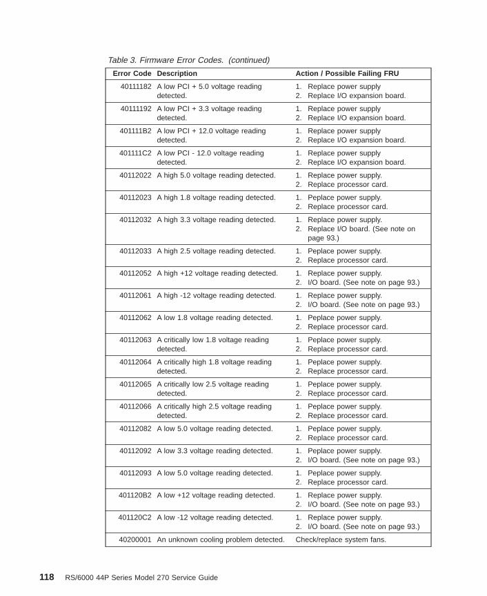
Table 3. Firmware Error Codes. (continued)
Error Code Description Action / Possible Failing FRU
40111182 A low PCI + 5.0 voltage readingdetected.
1. Replace power supply2. Replace I/O expansion board.
40111192 A low PCI + 3.3 voltage readingdetected.
1. Replace power supply2. Replace I/O expansion board.
401111B2 A low PCI + 12.0 voltage readingdetected.
1. Replace power supply2. Replace I/O expansion board.
401111C2 A low PCI - 12.0 voltage readingdetected.
1. Replace power supply2. Replace I/O expansion board.
40112022 A high 5.0 voltage reading detected. 1. Replace power supply.2. Replace processor card.
40112023 A high 1.8 voltage reading detected. 1. Peplace power supply.2. Replace processor card.
40112032 A high 3.3 voltage reading detected. 1. Replace power supply.2. Replace I/O board. (See note on
page 93.)
40112033 A high 2.5 voltage reading detected. 1. Peplace power supply.2. Replace processor card.
40112052 A high +12 voltage reading detected. 1. Replace power supply.2. I/O board. (See note on page 93.)
40112061 A high -12 voltage reading detected. 1. Replace power supply.2. I/O board. (See note on page 93.)
40112062 A low 1.8 voltage reading detected. 1. Peplace power supply.2. Replace processor card.
40112063 A critically low 1.8 voltage readingdetected.
1. Peplace power supply.2. Replace processor card.
40112064 A critically high 1.8 voltage readingdetected.
1. Peplace power supply.2. Replace processor card.
40112065 A critically low 2.5 voltage readingdetected.
1. Peplace power supply.2. Replace processor card.
40112066 A critically high 2.5 voltage readingdetected.
1. Peplace power supply.2. Replace processor card.
40112082 A low 5.0 voltage reading detected. 1. Peplace power supply.2. Replace processor card.
40112092 A low 3.3 voltage reading detected. 1. Peplace power supply.2. I/O board. (See note on page 93.)
40112093 A low 5.0 voltage reading detected. 1. Peplace power supply.2. Replace processor card.
401120B2 A low +12 voltage reading detected. 1. Replace power supply.2. I/O board. (See note on page 93.)
401120C2 A low -12 voltage reading detected. 1. Replace power supply.2. I/O board. (See note on page 93.)
40200001 An unknown cooling problem detected. Check/replace system fans.
118 RS/6000 44P Series Model 270 Service Guide

Table 3. Firmware Error Codes. (continued)
Error Code Description Action / Possible Failing FRU
40200021 A processor card temperature warningdetected.
1. Check system fans.2. Replace processor card(s).
40200023 A critical processor card temperaturecondition detected.
1. Check system fans.2. Replace processor card(s).
40200031 An I/O board temperature warningdetected.
1. Check system fans.2. I/O board. (See note on page 93.)
40200033 A critical I/O board temperaturecondition detected.
1. Check system fans.2. I/O board. (See note on page 93.)
40200051 An inlet temperature warning detected.(High temperature sensed at the air flowinlet).
1. Check/replace system fans.2. I/O board. (See note on page 93.)
40200053 An inlet memory temperature conditiondetected. (Critically high temperaturesensed at the air flow inlet).
1. Check/replace system fans.2. I/O board. (See note on page 93.)
40210011 A slow fan detected. 1. Check fan connector2. Replace failing fan.
40210014 A stopped fan detected. 1. Check fan connector2. Replace failing fan.
40A00000 System firmware IPL failure. 1. Press enter on an attached ASCIIterminal keyboard to go into theservice processor menus.
2. Select System Information Menu .3. Select ″Read Progress Indicators
from Last System Boot ″ and dothe action indicated for the postedcode identified by the arrow. If noarrow is present, do the actionindicated for the 4- or 8-digit codethat appears immediately below40A00000.Note: Refer to ″SP checkpoints″ or″Firmware checkpoints″ for help.
40B00000 The operating system surveillanceinterval exceeded.
1. Surveillance mode control is fromthe service processor menus.
2. Verify that the operating system(OS) heartbeat utility is installed andhas been activated.
3. Check for errors or unusualconditions that might prevent the OSfrom reporting heartbeat messages,such as system dump, machinecheck or checkstop error. Reviewthe error log.
4. I/O board. (See note on page 93.)5. If the problem persists, call the
support center for assistance.
Chapter 5. Error Code to FRU Index 119

Table 3. Firmware Error Codes. (continued)
Error Code Description Action / Possible Failing FRU
40D00003 An unknown slow shutdown occurred. Critical cooling problem. Check toensure the temperature is in theambient range.
40D00004 An unknown fast shutdown occurred. Locked fan failure detected. Make sureall fans are operating normally.
40D00101 BIST on I/O board failed. Replace I/O board. (See note on page93.)
40D00102 BIST on system board failed. Replace system board.
40D00200 Processor array initialization failed. Location code will point to failing FRU.
40D00201 JTAG chip ID miscompare. Location code will point to failing FRU.
450000C0 Uncorrectable memory error(checkstop).
1. If a physical location code isdisplayed in the operator panel or byAIX diagnostics, replace the FRU asindicated by the location code. If aphysical location code is notavailable, continue.
2. In the service processor menus, goto ″Read Progress Indicators fromlast System Boot″. If an arrow ispointing to a location code replacethe FRU at that location code. Ifthere is no arrow pointing to alocation code, continue.
3. Go to “MAP 1540: MinimumConfiguration” on page 50.
450000C1 Memory ECC correctable error(checkstop).
1. If a physical location code isdisplayed in the operator panel or byAIX diagnostics, replace the FRU asindicated by the location code. If aphysical location code is notavailable, continue.
2. In the service processor menus, goto ″Read Progress Indicators fromlast System Boot″. If an arrow ispointing to a location code replacethe FRU at that location code. Ifthere is no arrow pointing to alocation code, continue.
3. Go to “MAP 1540: MinimumConfiguration” on page 50.
120 RS/6000 44P Series Model 270 Service Guide

Table 3. Firmware Error Codes. (continued)
Error Code Description Action / Possible Failing FRU
450000C2 Memory ECC correctable errorthreshold exceeded (checkstop).
1. If a physical location code isdisplayed in the operator panel or byAIX diagnostics, replace the FRU asindicated by the location code. If aphysical location code is notavailable, continue.
2. In the service processor menus, goto ″Read Progress Indicators fromlast System Boot″. If an arrow ispointing to a location code replacethe FRU at that location code. Ifthere is no arrow pointing to alocation code, continue.
3. Go to “MAP 1540: MinimumConfiguration” on page 50.
450000C3 Memory controller subsystem internalerror (checkstop).
1. If a physical location code isdisplayed in the operator panel or byAIX diagnostics, replace the FRU asindicated by the location code. If aphysical location code is notavailable, continue.
2. In the service processor menus, goto ″Read Progress Indicators fromlast System Boot″. If an arrow ispointing to a location code replacethe FRU at that location code. Ifthere is no arrow pointing to alocation code, continue.
3. Go to “MAP 1540: MinimumConfiguration” on page 50.
450000C4 Memory address error (invalid addressor access attempt) (checkstop).
1. If a physical location code isdisplayed in the operator panel or byAIX diagnostics, replace the FRU asindicated by the location code. If aphysical location code is notavailable, continue.
2. In the service processor menus, goto ″Read Progress Indicators fromlast System Boot″. If an arrow ispointing to a location code replacethe FRU at that location code. Ifthere is no arrow pointing to alocation code, continue.
3. Go to“MAP 1540: MinimumConfiguration” on page 50.
Chapter 5. Error Code to FRU Index 121

Table 3. Firmware Error Codes. (continued)
Error Code Description Action / Possible Failing FRU
450000C5 Memory data error (bad data going tomemory) (checkstop).
1. If a physical location code isdisplayed in the operator panel or byAIX diagnostics, replace the FRU asindicated by the location code. If aphysical location code is notavailable, continue.
2. In the service processor menus, goto ″Read Progress Indicators fromlast System Boot″. If an arrow ispointing to a location code replacethe FRU at that location code. Ifthere is no arrow pointing to alocation code, continue.
3. Go to“MAP 1540: MinimumConfiguration” on page 50.
450000C6 Memory bus/switch internal error(checkstop).
1. If a physical location code isdisplayed in the operator panel or byAIX diagnostics, replace the FRU asindicated by the location code. If aphysical location code is notavailable, continue.
2. In the service processor menus, goto ″Read Progress Indicators fromlast System Boot″. If an arrow ispointing to a location code replacethe FRU at that location code. Ifthere is no arrow pointing to alocation code, continue.
3. Go to “MAP 1540: MinimumConfiguration” on page 50.
450000C7 Memory time-out error (checkstop). 1. If a physical location code isdisplayed in the operator panel or byAIX diagnostics, replace the FRU asindicated by the location code. If aphysical location code is notavailable, continue.
2. In the service processor menus, goto ″Read Progress Indicators fromlast System Boot″. If an arrow ispointing to a location code replacethe FRU at that location code. Ifthere is no arrow pointing to alocation code, continue.
3. Go to “MAP 1540: MinimumConfiguration” on page 50.
122 RS/6000 44P Series Model 270 Service Guide

Table 3. Firmware Error Codes. (continued)
Error Code Description Action / Possible Failing FRU
450000D0 System bus time-out error (checkstop). 1. If a physical location code isdisplayed in the operator panel or byAIX diagnostics, replace the FRU asindicated by the location code. If aphysical location code is notavailable, continue.
2. In the service processor menus, goto ″Read Progress Indicators fromlast System Boot″. If an arrow ispointing to a location code replacethe FRU at that location code. Ifthere is no arrow pointing to alocation code, continue.
3. Go to“MAP 1540: MinimumConfiguration” on page 50.
450000D1 System bus parity error (checkstop). 1. If a physical location code isdisplayed in the operator panel or byAIX diagnostics, replace the FRU asindicated by the location code. If aphysical location code is notavailable, continue.
2. In the service processor menus, goto ″Read Progress Indicators fromlast System Boot″. If an arrow ispointing to a location code replacethe FRU at that location code. Ifthere is no arrow pointing to alocation code, continue.
3. Go to “MAP 1540: MinimumConfiguration” on page 50.
450000D2 System bus protocol/transfer error(checkstop).
1. If a physical location code isdisplayed in the operator panel or byAIX diagnostics, replace the FRU asindicated by the location code. If aphysical location code is notavailable, continue.
2. In the service processor menus, goto ″Read Progress Indicators fromlast System Boot″. If an arrow ispointing to a location code replacethe FRU at that location code. Ifthere is no arrow pointing to alocation code, continue.
3. Go to “MAP 1540: MinimumConfiguration” on page 50.
Chapter 5. Error Code to FRU Index 123

Table 3. Firmware Error Codes. (continued)
Error Code Description Action / Possible Failing FRU
450000D3 I/O host bridge time-out error(checkstop).
1. If a physical location code isdisplayed in the operator panel or byAIX diagnostics, replace the FRU asindicated by the location code. If aphysical location code is notavailable, continue.
2. In the service processor menus, goto ″Read Progress Indicators fromlast System Boot″. If an arrow ispointing to a location code replacethe FRU at that location code. Ifthere is no arrow pointing to alocation code, continue.
3. Go to “MAP 1540: MinimumConfiguration” on page 50.
450000D4 I/O host bridge address/data bus parityerror (checkstop).
1. If a physical location code isdisplayed in the operator panel or byAIX diagnostics, replace the FRU asindicated by the location code. If aphysical location code is notavailable, continue.
2. In the service processor menus, goto ″Read Progress Indicators fromlast System Boot″. If an arrow ispointing to a location code replacethe FRU at that location code. Ifthere is no arrow pointing to alocation code, continue.
3. Go to “MAP 1540: MinimumConfiguration” on page 50.
450000D6 System support function error(checkstop).
1. If a physical location code isdisplayed in the operator panel or byAIX diagnostics, replace the FRU asindicated by the location code. If aphysical location code is notavailable, continue.
2. In the service processor menus, goto ″Read Progress Indicators fromlast System Boot″. If an arrow ispointing to a location code replacethe FRU at that location code. Ifthere is no arrow pointing to alocation code, continue.
3. Go to “MAP 1540: MinimumConfiguration” on page 50.
124 RS/6000 44P Series Model 270 Service Guide

Table 3. Firmware Error Codes. (continued)
Error Code Description Action / Possible Failing FRU
450000D7 System bus internal hardware/switcherror (checkstop).
1. If a physical location code isdisplayed in the operator panel or byAIX diagnostics, replace the FRU asindicated by the location code. If aphysical location code is notavailable, continue.
2. In the service processor menus, goto ″Read Progress Indicators fromlast System Boot″. If an arrow ispointing to a location code replacethe FRU at that location code. Ifthere is no arrow pointing to alocation code, continue.
3. Go to “MAP 1540: MinimumConfiguration” on page 50.)
450000DA All processor were found deconfigured,so the service processor reconfiguredthe best system processor that wasavaiable.
This SRN indicates that thecorresponding FRU has beenreconfigured, but it is not a warning oran error that this FRU is defective. Ifproblem persists with the reconfiguredprocessor even after power-on, replacethe defective FRUs as indicated inservice processor error log.
450000DB All DIMM pairs were founddeconfigured, so the service processorreconfigured the best DIMM pair thatwas available.
1. This SRN indicates that thecorresponding FRU has beenreconfigured, but it is not a warningor an error that this FRU isdefective. If problem persists withthe reconfigured DIMM pair evenafter power-on, replace it.
2. Replace the all DIMM pairs.
45800000 Memory controller checkstop. 1. Go to “MAP 1540: MinimumConfiguration” on page 50.
2. Replace system board.3. Replace I/O board. (See note on
page 93.)
45C00000 Memory checkstop. (Uncorrectablememory error.)
1. Attempt to reboot the system inservice mode to preserve the AIXerror log. If the reboot fails, attemptto reboot from the CD-ROM. If thereboot is successful, run diagnosticsin problem determination mode todetermine the cause of the failure.
2. Replace system board.3. Go to “MAP 1540: Minimum
Configuration” on page 50.
Chapter 5. Error Code to FRU Index 125

Table 3. Firmware Error Codes. (continued)
Error Code Description Action / Possible Failing FRU
460000C0 I/O bus address parity error (checkstop). 1. If a physical location code isdisplayed in the operator panel or byAIX diagnostics, replace the FRU asindicated by the location code. If aphysical location code is notavailable, continue.
2. In the service processor menus, goto ″Read Progress Indicators fromlast System Boot″. If an arrow ispointing to a location code replacethe FRU at that location code. Ifthere is no arrow pointing to alocation code, continue.
3. Go to “MAP 1540: MinimumConfiguration” on page 50.
460000C1 I/O bus data parity error (checkstop). 1. If a physical location code isdisplayed in the operator panel or byAIX diagnostics, replace the FRU asindicated by the location code. If aphysical location code is notavailable, continue.
2. In the service processor menus, goto ″Read Progress Indicators fromlast System Boot″. If an arrow ispointing to a location code replacethe FRU at that location code. Ifthere is no arrow pointing to alocation code, continue.
3. Go to “MAP 1540: MinimumConfiguration” on page 50.
460000C2 I/O bus time-out, access or other error(checkstop).
1. If a physical location code isdisplayed in the operator panel or byAIX diagnostics, replace the FRU asindicated by the location code. If aphysical location code is notavailable, continue.
2. In the service processor menus, goto ″Read Progress Indicators fromlast System Boot″. If an arrow ispointing to a location code replacethe FRU at that location code. Ifthere is no arrow pointing to alocation code, continue.
3. Go to “MAP 1540: MinimumConfiguration” on page 50.
126 RS/6000 44P Series Model 270 Service Guide

Table 3. Firmware Error Codes. (continued)
Error Code Description Action / Possible Failing FRU
460000C3 I/O bridge/device internal error(checkstop).
1. If a physical location code isdisplayed in the operator panel or byAIX diagnostics, replace the FRU asindicated by the location code. If aphysical location code is notavailable, continue.
2. In the service processor menus, goto ″Read Progress Indicators fromlast System Boot″. If an arrow ispointing to a location code replacethe FRU at that location code. Ifthere is no arrow pointing to alocation code, continue.
3. Go to “MAP 1540: MinimumConfiguration” on page 50.
460000C4 Error from a PCI to non-PCI bridge chip,indicating an error on the secondary bus
1. If a physical location code isdisplayed in the operator panel or byAIX diagnostics, replace the FRU asindicated by the location code. If aphysical location code is notavailable, continue.
2. In the service processor menus, goto ″Read Progress Indicators fromlast System Boot″. If an arrow ispointing to a location code replacethe FRU at that location code. Ifthere is no arrow pointing to alocation code, continue.
3. Go to “MAP 1540: MinimumConfiguration” on page 50.
460000C5 Mezzanine/system bus address parityerror (checkstop).
1. If a physical location code isdisplayed in the operator panel or byAIX diagnostics, replace the FRU asindicated by the location code. If aphysical location code is notavailable, continue.
2. In the service processor menus, goto ″Read Progress Indicators fromlast System Boot″. If an arrow ispointing to a location code replacethe FRU at that location code. Ifthere is no arrow pointing to alocation code, continue.
3. Go to “MAP 1540: MinimumConfiguration” on page 50.
Chapter 5. Error Code to FRU Index 127

Table 3. Firmware Error Codes. (continued)
Error Code Description Action / Possible Failing FRU
460000C6 Mezzanine/system bus data parity error(checkstop).
1. If a physical location code isdisplayed in the operator panel or byAIX diagnostics, replace the FRU asindicated by the location code. If aphysical location code is notavailable, continue.
2. In the service processor menus, goto ″Read Progress Indicators fromlast System Boot″. If an arrow ispointing to a location code replacethe FRU at that location code. Ifthere is no arrow pointing to alocation code, continue.
3. Go to “MAP 1540: MinimumConfiguration” on page 50.
460000C7 Mezzanine/system bus time-out, transferor protocol error (checkstop).
1. If a physical location code isdisplayed in the operator panel or byAIX diagnostics, replace the FRU asindicated by the location code. If aphysical location code is notavailable, continue.
2. In the service processor menus, goto ″Read Progress Indicators fromlast System Boot″. If an arrow ispointing to a location code replacethe FRU at that location code. Ifthere is no arrow pointing to alocation code, continue.
3. Go to “MAP 1540: MinimumConfiguration” on page 50.
460000D4 I/O expansion bus data parity or CRCerror protocol error (checkstop).
1. If a physical location code isdisplayed in the operator panel or byAIX diagnostics, replace the FRU asindicated by the location code. If aphysical location code is notavailable, continue.
2. In the service processor menus, goto ″Read Progress Indicators fromlast System Boot″. If an arrow ispointing to a location code replacethe FRU at that location code. Ifthere is no arrow pointing to alocation code, continue.
3. Go to “MAP 1540: MinimumConfiguration” on page 50.
128 RS/6000 44P Series Model 270 Service Guide

Table 3. Firmware Error Codes. (continued)
Error Code Description Action / Possible Failing FRU
460000D5 I/O expansion bus data time-out, accessor other error (checkstop).
1. If a physical location code isdisplayed in the operator panel or byAIX diagnostics, replace the FRU asindicated by the location code. If aphysical location code is notavailable, continue.
2. In the service processor menus, goto ″Read Progress Indicators fromlast System Boot″. If an arrow ispointing to a location code replacethe FRU at that location code. Ifthere is no arrow pointing to alocation code, continue.
3. Go to “MAP 1540: MinimumConfiguration” on page 50.
460000D6 I/O expansion bus connection failure(checkstop).
1. If a physical location code isdisplayed in the operator panel or byAIX diagnostics, replace the FRU asindicated by the location code. If aphysical location code is notavailable, continue.
2. In the service processor menus, goto ″Read Progress Indicators fromlast System Boot″. If an arrow ispointing to a location code replacethe FRU at that location code. Ifthere is no arrow pointing to alocation code, continue.
3. Go to “MAP 1540: MinimumConfiguration” on page 50.
460000D7 I/O expansion bus unit not in anoperating state (power down, off-line)(checkstop).
1. If a physical location code isdisplayed in the operator panel or byAIX diagnostics, replace the FRU asindicated by the location code. If aphysical location code is notavailable, continue.
2. In the service processor menus, goto ″Read Progress Indicators fromlast System Boot″. If an arrow ispointing to a location code replacethe FRU at that location code. Ifthere is no arrow pointing to alocation code, continue.
3. Go to “MAP 1540: MinimumConfiguration” on page 50.
Chapter 5. Error Code to FRU Index 129

Table 3. Firmware Error Codes. (continued)
Error Code Description Action / Possible Failing FRU
460000D8 A generic memory controller-detectedcheckstop has occured.
1. Try to reboot the system in servicemode to preserve the AIX error log.Run diagnostics in problemdetermination mode to determinethe cause of the failure if a newSRN or error code is generated,follow the actions for that code.
2. Try to boot AIX diagnostics fromCD-ROM.
v If the boot is successful, runadvanced diagnostics and followthe actions for any SRN or errorcode that is generated. If thesame error code is generated, goto “MAP 1540: MinimumConfiguration” on page 50.
v If AIX standalone diagnostics donot boot, follow the actions forany new SRN or error code thatis generated. If the same errorcode is generated, go to“MAP1540: Minimum Configuration” onpage 50.
460000D9 A generic I/O controller-detected,checkstop has occured.
1. Try to reboot the system in servicemode to preserve the AIX error log.Run diagnostics in problemdetermination mode to determinethe cause of the failure if a newSRN or error code is generated,follow the actions for that code.
2. Try to boot AIX diagnostics fromCD-ROM.
v If the boot is successful, runadvanced diagnostics and followthe actions for any SRN or errorcode that is generated. If thesame error code is generated, goto “MAP 1540: MinimumConfiguration” on page 50.
v If AIX standalone diagnostics donot boot, follow the actions forany new SRN or error code thatis generated. If the same errorcode is generated, go to “MAP1540: Minimum Configuration” onpage 50.
130 RS/6000 44P Series Model 270 Service Guide

Table 3. Firmware Error Codes. (continued)
Error Code Description Action / Possible Failing FRU
48800909 System VPD error. 1. Check cable to operator panel.2. Replace operator panel.3. Replace I/O board. (See note on
page 93.)4. Go to “MAP 1540: Minimum
Configuration” on page 50.
4880090A System planar VPD read fail. 1. Replace system planar.2. Replace I/O board. (See note on
page 93.)
4880090B Error identifying system type using VPD. 1. Check power supply cables.2. Call for support.
4880090C JTAG unable to confirm system typeusing system VPD.
1. Remove cards.2. Verify part numbers.3. Install valid cards.4. Call for support.
Chapter 5. Error Code to FRU Index 131

Table 3. Firmware Error Codes. (continued)
Error Code Description Action / Possible Failing FRU
4B2xxx00 Checkstop 1. Press enter on an attached ASCIIterminal keyboard to go into theservice processor menus.
2. Select System Information Menu .
3. Select ″Read Progress Indicatorsfrom Last System Boot ″ and usethe posted code indicated by thearrow. Refer to “Service ProcessorMenus” on page 149 if you needhelp. If the code is ″E105″,E14D,E15B, E174, E175, or ″0xxx″, wherexxx is any 3 digits, continue to step4 instead of the listed action.Otherwise, find the code in the“Service Processor Checkpoints” onpage 71 or “Firmware Checkpoints”on page 75 and perform the action
shown there.
4. Attempt to reboot the system inservice mode to preserve the AIXerror log. If the reboot fails, attemptto reboot from the CD-ROM. If thereboot is successful, run diagnosticsin problem determination mode todetermine the cause of the failure.Otherwise, continue.
5. Remove processor card in slot J8 (ifinstalled) and see if the problem isresolved. If problem is resolvedreplace processor card. If not,continue.
6. Exchange processor card in slot J6with processor card removed fromslot J8 in step 1 (replace processorcard if only one processor card isexists) and see if the problem isresolved. If problem is resolved,replace processor card. If not,continue.
7. Go to MAP 1540: MinimumConfiguration, “Step 1540-2” onpage 52.
132 RS/6000 44P Series Model 270 Service Guide

Table 3. Firmware Error Codes. (continued)
Error Code Description Action / Possible Failing FRU
4B2xxx01 Checkstop - Slot 1 (J6) Fail 1. Attempt to reboot the system inservice mode to preserve the AIXerror log. If the reboot fails, attemptto reboot from CD-ROM. If thereboot is successful, run diagnosticsin problem determination mode todetermine the cause of the failure.Otherwise, continue.
2. Processor card in slot 1 (J6)
3. System board
4. I/O board (See note on page 93.)
4B2xxx02 Checkstop - Slot 2 (J8) Fail 1. Attempt to reboot the system inservice mode to preserve the AIXerror log. If the reboot fails, attemptto reboot from the CD-ROM. If thereboot is successful, run diagnosticsin problem determination mode todetermine the cause of the failure.Otherwise, continue.
2. Processor card in slot 2 (J8)
3. System board
4. I/O board (See note on page 93.)
4B2xxx10 Machine Check - 0 1. Attempt to reboot the system inservice mode to preserve the AIXerror log. If the reboot fails, attemptto reboot from the CD-ROM. If thereboot is successful, run diagnosticsin problem determination mode todetermine the cause of the failure.Otherwise, continue.
2. Remove processor card in slot 2(J8) (if installed) and see if theproblem is resolved. If problem isresolved, replace processor card. Ifnot, continue.
3. Exchange processor card in slot 1(J6) with processor card removedfrom slot 2 (J8) in step 1 (replaceprocessor card if only one processorcard exists) and see if the problemis resolved. If problem is resolved,replace processor card. If not,continue.
4. Go to “MAP 1540: MinimumConfiguration” on page 50.
Chapter 5. Error Code to FRU Index 133

Table 3. Firmware Error Codes. (continued)
Error Code Description Action / Possible Failing FRU
4B2xxx11 Machine Check - 1 (Stuck Active) 1. Remove processor card in slot 2(J8) (if installed) and see if theproblem is resolved. If problem isresolved, replace processor card. Ifnot, continue.
2. Exchange processor card in slot 1(J6) with processor card removedfrom slot 2 (J8) in step 1 (replaceprocessor card if only one processorcard exists) and see if the problemis resolved. If problem is resolved,replace processor card. If not,continue.
3. Replace system board.
4B2xxx41 ABIST fail ABIST fail on first processor in slotidentified by location code displayed onoperator panel.
4B2xxx42 ABIST fail ABIST fail on second processor in slotidentified by location code displayed onoperator panel.
4B2xxx51 LBIST fail LBIST fail on first processor in slotidentified by location code displayed onoperator panel.
4B2xxx52 LBIST failed LBIST failed on second processor inslot identified by location code displayedon operator panel.
4B2xxxC0 CPU internal error (checkstop). 1. If a physical location code isdisplayed in the operator panel or byAIX diagnostics, replace the FRU asindicated by the location code. If aphysical location code is notavailable, continue.
2. In the service processor menus, goto ″Read Progress Indicators fromlast System Boot″. If an arrow ispointing to a location code replacethe FRU at that location code. Ifthere is no arrow pointing to alocation code, continue.
3. Go to “MAP 1540: MinimumConfiguration” on page 50.
134 RS/6000 44P Series Model 270 Service Guide

Table 3. Firmware Error Codes. (continued)
Error Code Description Action / Possible Failing FRU
4B2xxxC1 CPU internal cache or cache controllererror (checkstop).
1. If a physical location code isdisplayed in the operator panel or byAIX diagnostics, replace the FRU asindicated by the location code. If aphysical location code is notavailable, continue.
2. In the service processor menus, goto ″Read Progress Indicators fromlast System Boot″. If an arrow ispointing to a location code replacethe FRU at that location code. Ifthere is no arrow pointing to alocation code, continue.
3. Go to “MAP 1540: MinimumConfiguration” on page 50.
4B2xxxC2 External cache parity or multi-bit ECCerror (checkstop).
1. If a physical location code isdisplayed in the operator panel or byAIX diagnostics, replace the FRU asindicated by the location code. If aphysical location code is notavailable, continue.
2. In the service processor menus, goto ″Read Progress Indicators fromlast System Boot″. If an arrow ispointing to a location code replacethe FRU at that location code. Ifthere is no arrow pointing to alocation code, continue.
3. Go to “MAP 1540: MinimumConfiguration” on page 50.
4B2xxxC3 External cache ECC single-bit ECCerror (checkstop).
1. If a physical location code isdisplayed in the operator panel or byAIX diagnostics, replace the FRU asindicated by the location code. If aphysical location code is notavailable, continue.
2. In the service processor menus, goto ″Read Progress Indicators fromlast System Boot″. If an arrow ispointing to a location code replacethe FRU at that location code. Ifthere is no arrow pointing to alocation code, continue.
3. Go to “MAP 1540: MinimumConfiguration” on page 50.
Chapter 5. Error Code to FRU Index 135

Table 3. Firmware Error Codes. (continued)
Error Code Description Action / Possible Failing FRU
4B2xxxC4 System bus time-out error (checkstop). 1. Replace the FRU as indicated bythe physical location code displayedon the operator panel and rebootthe system.
2. If the system fails to boot, reinstallthe card removed in step 1.
3. Replace the other processor cardand reboot the system.
4. If the system boots, the processorcard pulled in step 3 is at fault.
5. If system still fails to boot, replacesystem board. (See note on page93.)
4B2xxxC5 System bus time-out error, waiting forI/O (checkstop).
1. If a physical location code isdisplayed in the operator panel or byAIX diagnostics, replace the FRU asindicated by the location code. If aphysical location code is notavailable, continue.
2. In the service processor menus, goto ″Read Progress Indicators fromlast System Boot″. If an arrow ispointing to a location code replacethe FRU at that location code. Ifthere is no arrow pointing to alocation code, continue.
3. Go to “MAP 1540: MinimumConfiguration” on page 50.
4B2xxxC6 System bus parity error (checkstop). 1. If a physical location code isdisplayed in the operator panel or byAIX diagnostics, replace the FRU asindicated by the location code. If aphysical location code is notavailable, continue.
2. In the service processor menus, goto ″Read Progress Indicators fromlast System Boot″. If an arrow ispointing to a location code replacethe FRU at that location code. Ifthere is no arrow pointing to alocation code, continue.
3. Go to “MAP 1540: MinimumConfiguration” on page 50.
136 RS/6000 44P Series Model 270 Service Guide

Table 3. Firmware Error Codes. (continued)
Error Code Description Action / Possible Failing FRU
4B2xxxC7 System bus protocol/transfer error(checkstop).
1. If a physical location code isdisplayed in the operator panel or byAIX diagnostics, replace the FRU asindicated by the location code. If aphysical location code is notavailable, continue.
2. In the service processor menus, goto ″Read Progress Indicators fromlast System Boot″. If an arrow ispointing to a location code replacethe FRU at that location code. Ifthere is no arrow pointing to alocation code, continue.
3. Go to “MAP 1540: MinimumConfiguration” on page 50.
4B2xxxC8 A generic processor-detected checkstophas occured.
1. Try to reboot the system in servicemode to preserve the AIX error log.Run diagnostics in problemdetermination mode to determinethe cause of the failure if a newSRN or error code is generated,follow the actions for that code.
2. Try to boot AIX diagnostics fromCD-ROM.
v If the boot is successful, runadvanced diagnostics and followthe actions for any SRN or errorcode that is generated. If thesame error code is generated, goto “MAP 1540: MinimumConfiguration” on page 50.
v If AIX standalone diagnostics donot boot, follow the actions forany new SRN or error code thatis generated. If the same errorcode is generated, go to “MAP1540: Minimum Configuration” onpage 50.
4B20000A All processors got deconfigured. 1. Replace processor card.
2. Replace system board
Chapter 5. Error Code to FRU Index 137

Table 3. Firmware Error Codes. (continued)
Error Code Description Action / Possible Failing FRU
4B200043 Service processor reports JTAG fail 1. Remove processor card in slot 2(J8) (if installed) and see if theproblem is resolved. If not, proceedto step 2.
2. Exchange processor card in slot 1(J6) with processor card removedfrom slot 2 (J8) in step 1 (replaceprocessor card if only one processorcard exists) and see if the problemis resolved. If not, proceed to step 3.
3. Replace system board.
4. Replace I/O board. (See note onpage 93.)
4B200055 No processor found. 1. If only one processor card is used, itmust be in slot 1 (J6).
2. If two processor cards are beingused, replace the card in slot 1 (J6).
4B200056 No processor found 1. If only one processor card is used, itmust be in slot 1 (J6).
2. If two processor cards are beingused, replace the card in slot 1 (J6).
4B200057 The processor cards are not compatiblewith each other.
1. Remove cards
2. Verify part numbers
3. Install valid cards.
4B200058 Compatibility test on processor card 1(J6) failed.
1. Remove cards
2. Verify part numbers
3. Install valid cards.
4B200059 Compatibility test on processor card 2(J8) failed.
1. Remove cards
2. Verify part numbers
3. Install valid cards.
4BA00000 The system support controller detectsthe service processor, but cannotestablish communication. The systemhalts.
1. Power down the system unit:
a. Unplug the power cord.
b. Plug in the power cord andpower up the system unit.
2. Replace I/O board. (See note 3 onpage 93.)
4BA00001 The system support controller cannotdetect the service processor.
Replace the I/O board. (See note onpage 93.)
4BA00800 Unknown error. 1. Check level of service processorfirmware; update if nesessary.
2. If problelm persists, call for support.
138 RS/6000 44P Series Model 270 Service Guide

Table 3. Firmware Error Codes. (continued)
Error Code Description Action / Possible Failing FRU
4BA00826 Service processor cannot call home. 1. Check modem configuration inservice processor menus.
2. Check modem connections.3. Replace the I/O board. (See note on
page 93.)
4BA00827 Flash update diskette fail. 1. Copy the flash update image onto abrand new diskette that has beendos-formatted.
2. The image name on the diskettemust be ″spflash.img″.
3. Verify that the flash update image isthe correct one for the machinetype.
4. Turn ac power off, then on, and retryflash update.
5. Replace diskette drive.
4BA00828 Flash update (crc) checksum fail. Copy the flash image onto a new,dos-formatted diskette and retry theflash update.
4BA00829 Bad system firmware. Replace the I/O board. (See note onpage 93.)
4BA00830 Boot fail. Go to “Boot Problems/Concerns” onpage 89.
4BA00831 Bad service processor firmware image. 1. Ungpug the machine from ac power,wait a few moments, and attempt toreboot. Pay close attention to theprogress code the machine hangson (if it does hang on one) and referto description of that progress code .
2. Replace the I/O board. (See note onpage 93.)
4BA00832 Error while doing flash update. 1. Re-power the system; retry the flashprogramming a few times.
2. Replace I/O board. (See note onpage 93.)
4BA10001 SSC sram fail 1. Restore or update the serviceprocessor flash EPROM.
2. Replace I/O board. (See note onpage 93.)
4BA10002 SSC sram fail. 1. Go to “MAP 1540: MinimumConfiguration” on page 50.
2. Replace I/O board. (See note onpage 93.)
4BA10003 Service processor hardware fail. Replace I/O board. (See note on page93.)
Chapter 5. Error Code to FRU Index 139

Table 3. Firmware Error Codes. (continued)
Error Code Description Action / Possible Failing FRU
4BA10004 Service processor firmware fail. 1. Restore or update the serviceprocessor firmware.
2. Replace I/O board. (See note onpage 93.)
4BA10005 Path fail 1. Replace I/O board. (See note onpage 93.)
2. Replace processor card.3. Replace system board.
4BA10832 Error while doing flash update. 1. Power-on the system unit.2. Do the following flash recovery
procedure:a. Insert a newly formatted DOS
diskette loaded with serviceprocessor firmware into thediskette drive. The file namemust be spflash.img.
b. Shutdown the system unit andunplug the power cable.
c. Plug in the power cable,power-on the system unit.
3. Retry item 2 with a newly formattedDOS diskette.
4. Go to “MAP 1540: MinimumConfiguration” on page 50.
4BA80013 NVRAM 1. Unplug the system unit. Manuallyclear NVRAM. Remove the batteryand use it to short the battery leadsfor at least 30 seconds. Power-upthe system unit.
2. Go to “MAP 1540: MinimumConfiguration” on page 50.
4BA80014 NVRAM checksum (CRC) fail. 1. Unplug the system unit. Manuallyclear NVRAM. Remove the batteryand use it to short the battery leadsfor at least 30 seconds. Power-upthe system unit.
2. Go to “MAP 1540: MinimumConfiguration” on page 50.
4BA80015 NVRAM reinitialization fail. 1. Unplug the system unit. Manuallyclear NVRAM. Remove the batteryand use it to short the battery leadsfor at least 30 seconds. Power-upthe system unit.
2. Go to “MAP 1540: MinimumConfiguration” on page 50.
140 RS/6000 44P Series Model 270 Service Guide

Memory Problem Determination BitsThe following table expands the firmware error code 25Cyyxxx on page 102, where yyis the PD values in the table below and xxx are the last three digits of the error code.Use these values to identify the type of memory that generated the error.
If you replace FRUs and the problem is still not corrected, go to “MAP 1540: MinimumConfiguration” on page 50 unless otherwise indicated in the tables.
Table 4. Memory Module PD bits
PD value Size Clock Cycle (nsecs) Parity/ ECC
28 512MB 10 ECC
2A 512MB 8 ECC
38 128MB 10 ECC
3A 128MB 8 ECC
48 64MB 10 ECC
4A 64MB 8 ECC
58 32MB 10 ECC
5A 32MB 8 ECC
68 256MB 10 ECC
6A 256MB 8 ECC
Note: Memory modules must be installed in pairs.
Chapter 5. Error Code to FRU Index 141

Bus SRN to FRU Reference TableThis table is used to locate defective FRUs within the I/O board’s PCI and ISA buses.The table indicates which devices should be tested for each SRN. For this procedure, ifpossible, diagnostics are run on the I/O board bus devices with all adapters removedfrom the failing bus. If a failure is detected on this system with all adapters removedfrom the failing bus, the I/O board is the isolated FRU. If a failure is not detected, theadapters are added back one at a time to their original slot location, and theconfiguration is tested until a failure is detected. The failure is then isolated to the failingFRU.
If a failure has not been detected and all the FRUs have been tested, call technicalservice support for assistance.
Table 5. Bus SRN to FRU Reference TableSRN Bus
IdentificationPossible Failing Device and AIXLocation Code
Associated FRU
9CC-100 PCI Bus 00 Internal SCSI port (10-60) I/O board. (See note onpage 93.)
External SCSI port (10-88) I/O board. (See note onpage 93.)
Internal Ethernet port (10-80) I/O board. (See note onpage 93.)
Device installed in I/O slot 3P (10-68to 10-6F)
Adapter
Device installed in I/O slot 4P (10-70to 10-77)
Adapter
Device installed in I/O slot 5P (10-78to 10-7F)
Adapter
9CC-101 PCI Bus 40 Device installed in I/O slot 1P (20-58to 20-5F)
Adapter
Device installed in I/O slot 2P (20-60to 20-67)
Adapter
651-730 ISA Bus Diskette drive port/device(01-D1-00-00)
I/O board. (See note onpage 93.)
Parallel port/device (01-R1) I/O board. (See note onpage 93.)
Serial ports (1-2)/device (01-S1 to01-S2)
I/O board. (See note onpage 93.)
Mouse port/device (01-K1-01-00) I/O board. (See note onpage 93.)
Keyboard port/device (01-K1-00-00) I/O board. (See note onpage 93.)
Audio port/device (01-Q2) I/O board. (See note onpage 93.)
Tablet port/device (01-Q1) I/O board. (See note onpage 93.)
142 RS/6000 44P Series Model 270 Service Guide

Typical Boot SequenceAfter the ac power is turned on, the System Support Controller (SSC) startup begins theservice processor. If the SSC cannot communicate with the service processor, the LCDdisplays 4BA00000. If the service processor is not present, the LCD displays4BA00001.
1. Service processor self-test
v Service processor card performs self-test and NVRAM initialization.
v LCD code range is E000 - E07F.
v LCD code is OK when complete.
2. Service processor in standby mode
v You can enter the service processor menus whenever the LCD code is OK,STBY, or has an eight-digit error code on the LCD display, by pressing the Enterkey on an ASCII terminal connected to serial port 1.
3. Built-In-Self-Test (BIST)
v The service processor initiates built-in-self-test (BIST) on the central electronicscomplex (CEC) chips when the Power button is pressed.
v The VPD data are read and the CRC is checked.
v The processor compatibility test is run.
v LCD code range is E0A0 - E0E1.
4. System Initialization
v System firmware begins to execute and initializes system registers after LCDcode E0E1.
v LCD code range is E1XX - E2XX.
5. Memory Test
v The system firmware tests the system memory and identifies failing memorycards and memory module locations.
v LCD code range is E3XX.
6. Device Configuration and Test
v System firmware checks to see which devices are in the system and performs asimple test on them.
v The system firmware displays the device name or device icon being tested. Afterthe keyboard name or icon appears, the user can enter the System ManagementServices menu by pressing the 1 key (if ASCII terminal) or the F1 key (if graphicsterminal).
v The user can also enter one of the following:
– 5 or F5 to start the standalone diagnostics (CD).
– 6 or F6 to start the online diagnostics (disk drive).
v IPL Boot Code
– The system firmware attempts to boot from the devices listed in the boot list.
– LCD code range is E1XX.
v Boot Image Execution
Chapter 5. Error Code to FRU Index 143

– After a boot image is located on a device in the boot list, the system firmwarecode passes control to one of the following AIX Boot codes:
- LCD code E105 for normal boot
- LCD code E15B for service mode boot.
– The AIX boot code displays LCD progress codes in the format 0XXX.
v AIX boot complete
– The AIX login prompt displays on the main console.
144 RS/6000 44P Series Model 270 Service Guide

Chapter 6. Loading the System Diagnostics
The system diagnostics can be booted either from the default boot list or from theservice mode boot list. (The service mode boot list can be modified using the systemdiagnostics ″Display or Change Bootlist″ service aid. The service mode boot list cannotbe modified under the System Management Services.)
Performing Slow BootTo fully analyze all of the available information, perform the following steps before doinga hardware repair or replacement, especially if the error is related to the CPU ormemory.
1. Record the 8-character error code (and location code if present) displayed in theoperator panel, or that was reported by the customer.
2. Do a slow-mode boot in service mode. This can be specified using the SystemPower Control Menu on the service processor main menu. (A fast-mode boot skipsmuch of the built-in diagnostic testing.) A slow-mode boot may yield a new8-character error code on the operator panel and new errors in the serviceprocessor error log. If a new error code is reported, use it in subsequent steps tocontinue problem analysis.
Standalone DiagnosticsTo load standalone diagnostics from the default boot list, perform the followingprocedure:
1. Verify with the system administrator and users that all programs may be stopped,then do so.
2. Turn off the system.
3. Wait 30 seconds, and turn on the system.
4. Immediately insert the diagnostic CD-ROM into the CD-ROM drive.
5. When or after the keyboard indicator appears during startup, press the F5 key on adirectly attached keyboard (or the number 5 key on an ASCII terminal).
6. Enter any requested passwords.
Online DiagnosticsOnline diagnostics can be loaded by booting from the service mode boot list bypressing the F6 key (on a directly attached keyboard) or the number 6 key on an ASCIIterminal.
The procedure for booting from the devices listed in the service mode boot list (OnlineDiagnostics ) is as follows:
1. Verify with the system administrator and users that all programs may be stopped,then do so.
2. Turn off the system.
145

3. Wait 30 seconds, and turn on the system.
4. When or after the keyboard indicator appears during startup, press the F6 key on adirectly attached keyboard (or the number 6 key on an ASCII terminal).
5. Enter any requested passwords.
After any requested passwords have been entered, the system attempts to boot fromthe first device of each type found on the list. If no bootable image is found on the firstdevice of each type on the list, the system does not search through the other devices ofthat type for a bootable image. Instead, it polls the first device of the next type.
If all types of devices in the boot list have been polled without finding a bootable image,the system restarts, giving the user the opportunity to start the System ManagementServices (by pressing the F1 key on a directly attached keyboard or the number 1 onan ASCII terminal) before the system attempts to boot again.
Default Boot List and Service Mode Boot ListThe default boot list is as follows:
1. Diskette drive
2. CD-ROM drive
3. Tape drive
4. Disk drive
5. Network adapter
v Token-ring
v Ethernet
Pressing the F5 key on a directly attached keyboard (or the number 5 key on an ASCIIterminal) causes the system to load standalone diagnostics provided that a diagnosticCD is present in the CD-ROM drive.
Pressing the F6 key on a directly attached keyboard (or number 6 key on an ASCIIterminal) loads online diagnostics from the service mode boot list. No diagnostic CDshould be in the CD-ROM drive because online diagnostics is typically run from a harddisk, which is in the service mode boot list defined using the system diagnostics″Display or Change Bootlist″ service aid. Like the default boot list, the service modeboot list can contain five entries. The F6 and 6 keys work like the F5 and 5 keys, withthe following exceptions:
v The system searches for a boot record according to the service mode boot list.
v If the service mode boot list is discovered by a cyclical redundancy check to becorrupted, the system rebuilds the service mode boot list according to the defaultboot list. (The default boot list contains five entries, and for each matching devicetype found in the system unit, the system makes an entry in the service mode bootlist.)
v If no service mode boot list is present, the system uses the default boot list.
146 RS/6000 44P Series Model 270 Service Guide

Chapter 7. Using the Service Processor
The service processor menus enable you to configure service processor options and toenable and disable functions.
Service processor menus are available using an ASCII terminal when the server isturned off and the service processor is operating with standby power. Service processormenus are also available when server power is on and the service processor hasdetected a server problem (such as loss of surveillance).
During the first power-up (that is, the power cord is plugged into the outlet), serviceprocessor menus are not available for 45 seconds while the service processor isrunning self-tests and initializing the server. If the server powers down, serviceprocessor menus become available after 15 seconds.
For a summary of the service processor functions and the methods for invoking them,see the table below.
147

Service Processor Functions ServiceProcessor
Menus (ASCIIterminals)
AIX ServiceAids (ASCII or
graphicsterminals)
SMS (ASCII orgraphics
terminals)
View System Environmental Conditions Y3
Read System POST Errors Y3
Read Service Processor Error Logs Y3
View Progress Indicators from last Boot Y3
Power-on System Y3
Power-off System Y2
Read NVRAM Y2
Reset Service Processor Y2
Setup Reboot/Restart Policy Y2
Start Talk Mode Y2
Enable/Disable Console Mirroring Y2 Y1
Select Modem Line Speed Y2 Y1
Enable/Disable Modem Y2 Y1
Setup Modem Configuration Y2 Y1
Setup Ring Indicate Power-On Y2 Y1
Setup Dial-out Phone Numbers Y2 Y1
Setup Surveillance Y2 Y1
Update Service Processor Flash EPROM Y2 Y1 Y2
Change General-Access Password Y2 Y2
Change Privileged-access Password Y2 Y2
Select Language Y2 Y2
Enable/Disable Unattended Start Mode Y2 Y2
1 Operating system root password
2 Privileged-access password
3 General-access (power-on) password
148 RS/6000 44P Series Model 270 Service Guide

Service Processor MenusThe service processor menus are divided into two groups:
v General user menus - the user must know the general-access password.
v Privileged user menus - the user must know the privileged-access password.
The following section describes these two groups of menus, how to access them, andthe functions associated with each option.
When the server is powered down, the service processor menus can be accessedlocally or remotely.
Service Processor Menu InactivityTo prevent loss of control in unstable power environments, the service processor leavesthe menu mode after five minutes of inactivity. Return to the menus by pressing any keyon the local or remote terminal.
Accessing Service Processor Menus LocallyService processor menus can be accessed locally by connecting an ASCII terminal toeither serial port. Because the presence of the ASCII terminal cannot be confirmed bythe service processor, you must press a key on the ASCII terminal to confirm itspresence after OK appears in the operator panel display. The service processor thenprompts you for a password (if set), and when verified, displays the service processormenus.
Accessing Service Processor Menus RemotelyService processor menus can be accessed remotely by connecting a modem to serialport 1 or serial port 2, as follows:
1. Turn off the server, unplug the power cord, and press the Power button to draincapacitance while power is disconnected.
2. Connect the modem to the appropriate serial port and turn on the modem.
3. Plug in the server.
Note:
If your modem has not been configured, go to “Call-In/Call-Out Setup Menu” onpage 165, and with a terminal or terminal emulator, call the server’s modem.
The service processor prompts you for a password (if set), and when verified,displays the service processor menus.
Chapter 7. Using the Service Processor 149

General User MenuThe menu options presented to the general user are a subset of the options available tothe privileged user. The user must know the general-access password, if set, to accessthese menus.
GENERAL USER MENU
1. Power-On System2. Read VPD Image from Last System Boot3. Read Progress Indicators from Last System Boot4. Read Service Processor Error Logs5. Read System POST Errors6. View System Environmental Conditions
99. Exit from Menus
1>
Note: The service processor prompt displays either 1> or 2> to indicate which serialport on the system unit is being used to communicate with the service processor.
v Power-On System
Allows the user to power-on the system.
v Read VPD Image from Last System Boot
Displays manufacturer vial product data, such as serial numbers, part numbers, andso on, that were stored from the system boot prior to the one in progress now.
v Read Progress Indicators from Last System Boot
Displays the boot progress indicators (checkpoints), up to a maximum of 100, fromthe system boot prior to the one in progress. This historical information can be usefulto help diagnose system faults.
The progress indicators are displayed in two sections. Above the dashed line are theprogress indicators (latest) from the boot that produced the current sessions. Belowthe dashed line are progress indicators (oldest) from the boot preceding the one thatproduced the current sessions.
The progress indicator codes are listed from top (latest) to bottom (oldest). Thedashed line represents the point where the latest boot started.
If the <-- arrow occurs, use the 4-digit checkpoint or 8-digit error code being pointedto as the starting point for your service actions.
v Read Service Processor Error Logs
Displays the service processor error logs.
The time stamp in this error log is coordinated universal time (CUT), also known asGreenwich Mean Time (GMT). AIX error logs have additional information availableand are able to time stamp the errors with local time. See “Error Log” on page 198for an example of the error log.
150 RS/6000 44P Series Model 270 Service Guide

v Read System POST Errors
Select this item to review the results of the POST (power-on self-test). Your servermay be able to start in the presence of POST errors if there are sufficient workingsystem resources. If POST errors occur during startup, this error log, when used withthe diagnostics, helps to isolate faults. See “System POST Errors” on page 180 foran example of the POST error screen.
v View System Environmental Conditions
With this menu option, the service processor reads all environmental sensors andreports the results to the user. This option can be useful when surveillance fails,because it allows the user to determine the environmental conditions that may berelated to the failure.
Privileged User MenusThe following menus are available to privileged users only. The user must know theprivileged-access password, if set, to access these menus.
Main MenuAt the top of the Main Menu is a listing containing:
v Your service processor’s current firmware version
v The firmware copyright notice
v The system name given to your server during setup (optional)
You need the firmware version for reference when you either update or repair thefunctions of your service processor.
The system name, an optional field, is the name that your server reports in problemmessages. This name helps your support team (for example, your system administrator,network administrator, or service representative) to more quickly identify the location,configuration, and history of your server. The system name is set from the Main Menuusing option 6.
Chapter 7. Using the Service Processor 151

Note: The information under the Service Processor Firmware heading in the followingMain Menu illustration is example information only.
Service Processor FirmwareFirmware Level: sh991029
Copyright 1997, IBM CorporationSYSTEM NAME
MAIN MENU
1. Service Processor Setup Menu2. System Power Control Menu3. System Information Menu4. Language Selection Menu5. Call-In/Call-Out Setup Menu6. Set System Name
99. Exit from Menus
1>
Service Processor Setup MenuThe Service Processor Setup menu shown below is accessed from the Main Menu:
SERVICE PROCESSOR SETUP MENU
1. Change Privileged-access Password2. Change General-Access Password3. Enable/Disable Console Mirroring:
Currently Disabled
4. Start Talk Mode5. OS Surveillance Setup Menu6. Reset Service Processor7. Reprogram Service Processor Flash EPROM8. Serial Port Snoop Setup Menu
98. Return to Previous Menu99. Exit from Menus
1>
Note: Unless otherwise stated in the menu responses, setings become effective whena menu is exited using option 98 or 99.
152 RS/6000 44P Series Model 270 Service Guide

PasswordsPasswords can be any combination of up to eight alphanumeric characters. You canenter longer passwords, but the entries are truncated to include only the first eightcharacters. Passwords can be set from the service processor menu or from the SystemManagement Services menus.
For security purposes, the service processor counts the number of attempts to entercorrect passwords. The results of not recognizing a correct password within this errorthreshold are different, depending on whether the attempts are being made locally (atthe server) or remotely (through a modem). The error threshold is three attempts.
If the error threshold is reached by someone entering passwords at the server, theservice processor exits the menus. This action is taken based on the assumption thatthe server is in an adequately secure location with only authorized users having access.Such users must still successfully enter a login password to access AIX.
If the error threshold is reached by someone entering passwords remotely, the serviceprocessor disconnects the modem to prevent potential security attacks on the server byunauthorized remote users.
The following table illustrates what you can access with the privileged-access passwordand the general-access password.
Privileged-Access Password General-Access Password Resulting Menu
None None MAIN MENU displays
None Set MAIN MENU displays
Set None Users with password see theMAIN MENU. Other users seethe GENERAL USER MENU.
Set Set Users see menus associatedwith the entered password
v Change Privileged-access Password
Set or change the privileged-access password. It provides the user with the capabilityto access all service processor functions. This password is usually used by thesystem administrator or root user.
v Change General-Access Password
Set or change the general-access password. It provides limited access to serviceprocessor menus and is usually available to all users who are allowed to power onthe server.
v Enable/Disable Console Mirroring
When console mirroring is enabled, the service processor sends information to bothserial ports. This capability, which can be enabled by local or remote users, provideslocal users with the capability to monitor remote sessions. Console mirroring can beenabled for the current session only. For more information, see “Console Mirroring”on page 179.
v Start Talk Mode
Chapter 7. Using the Service Processor 153

In a console-mirroring session, it is useful for those who are monitoring the sessionto be able to communicate with each other. Selecting this menu item activates thekeyboards and displays for such communications while console mirroring isestablished. This is a full duplex link, so message interference is possible. Alternatingmessages between users works best.
154 RS/6000 44P Series Model 270 Service Guide

v OS Surveillance Setup Menu
This menu can be used to set up operating system (OS) surveillance.
OS Surveillance Setup Menu
1. Surveillance:Currently Enabled
2. Surveillance Time Interval:5 Minutes
3. Surveillance Delay:10 Minutes
98. Return to Previous Menu
v Surveillance
Can be set to enabled or disabled.
v Surveillance Time Interval
Can be set to any number from 1 to 255 minutes. The default value is 5 minutes.
v Surveillance Delay
Can be set to any number from 0 to 255 minutes. The default value is 10 minutes.
Surveillance time interval and surveillance delay can only be changed after surveillanceis enabled.
Refer to “Service Processor System Monitoring - Surveillance” on page 177 for moreinformation about surveillance.
v Reset Service Processor
Allows the user to reinitialize the service processor.
v Reprogram Service Processor Flash EPROM
Attention: Only the service processor firmware can be updated from the serviceprocessor menus; the system firmware cannot be updated from the service processormenus. A service processor firmware update always requires a companion systemfirmware update which must be applied first. For this reason, updating only theservice processor firmware using the service processor menus is not recommended.Go to the RS/6000 support web site at http://www.rs6000.ibm.com/support/micro todownload the latest firmware levels and update instructions.
The service processor firmware update image must be written onto a DOS-formatteddiskette. The update image can be obtained from the RS/6000 support web site:http://www.rs6000.ibm.com/support/micro.
After the update diskette has been made, from the service processor main menu,select ″Service Processor Setup″. Then select ″Reprogram Service Processor FlashEPROM″. The program requests the update diskette(s) as they are needed. Theservice processor will automatically reboot after the firmware update is complete.
Chapter 7. Using the Service Processor 155

Serial Port Snoop Setup MenuThis menu can be used to setup serial port snooping, in which the user can configureserial port 1 as a ″catch-all″ reset device.
From the main service processor menu, select option 1, Service Processor Setup, thenselect option 8 (Serial Port Snoop Setup Menu).
SERIAL PORT SNOOP SETUP MENU
1. System reset string:Currently Unassigned
2. Snoop Serial Port:Currently Unassigned
98. Return to Previous Menu
1>
Use the system reset string option to enter the system reset string, which resets themachine when it is detected on the main console on serial port 1.
Use the snoop serial port option to select the serial port to snoop.
Note: Only serial port 1 is supported.
After serial port snooping is correctly configured, at any point after the system unit isbooted to AIX, whenever the reset string is typed on the main console, the system unituses the service processor reboot policy to restart. This action causes an EPOW (EarlyPower Off Warning) to be logged, and also an AIX dump to be created if the machine isat an AIX prompt, with AIX in such a state that it can respond. If AIX cannot respond,the EPOW record is created, rather than the AIX dump.
Pressing Enter after the reset string is not required, so make sure that the string is notcommon or trivial. A mixed-case string is recommended.
156 RS/6000 44P Series Model 270 Service Guide

System Power Control MenuThe menu is used to set power control options.
SYSTEM POWER CONTROL MENU
1. Enable/Disable Unattended Start Mode:Currently Disabled
2. Ring Indicate Power-On Menu3. Reboot/Restart Policy Setup Menu4. Power-On System5. Power-Off System6. Enable/Disable Fast System Boot:
Currently Disabled7. Boot Mode Menu98. Return to Previous Menu99. Exit from Menus
1>
v Enable/Disable Unattended Start Mode
Use this option to instruct the service processor to immediately power-on the serverafter a power failure, bypassing power-on password verification. Unattended startmode can also be set using SMS menus. Unattended start mode can be used onservers that require automatic power-on after a power failure.
v Ring Indicate Power-On Menu
Ring indicate power-on is an alternate method of dialing in without establishing aservice processor session. If the system is powered off and ring indicate power-on isenabled, the server is powered on at the predetermined number of rings. If the serveris already on, no action is taken. In either case, the telephone call is not answered.The caller receives no feedback that the server is powered on. The Ring IndicatePower-On Menu and defaults are shown below:
Ring Indicate Power-On Menu
1. Ring indicate power-on:Currently Disabled
2. Number of rings:Currently 6
98. Return to Previous Menu
The number of rings can be set to any number greater than zero. The default valueis six rings.
Chapter 7. Using the Service Processor 157

v Reboot/Restart Policy Setup Menu
Reboot describes bringing the system hardware back up from scratch, for example,from a system reset or power-on. The reboot process ends when control passes tothe operating system loading (or initialization) process.
Restart describes activating the operating system after the system hardwarereinitialized. Restart must follow a successful reboot.
Reboot/Restart Policy Setup Menu
1. Number of reboot attempts:Currently 3
2. Use OS-Defined restart policy?Currently Yes
3. Enable supplemental restart policy?Currently No
4. Call-Out before restart:Currently Disabled
98. Return to Previous Menu
1>
– Number of reboot attempts If the server fails to successfully complete the bootprocess, it attempts to reboot the number of times specified. Values equal to orgreater than 0 are valid. Only successive failed reboot attempts count, not rebootsthat occur after a restart attempt. At restart, the counter is set to 0.
– Use OS-Defined restart policy lets the service processor react or not react thesame way as the operating system to major system faults by reading the settingof the operating system parameter Automatically Restart/Reboot After aSystem Crash . This parameter may or may not be defined, depending on theoperating system or its version and level. If the operating system automatic restartsetting is defined, then it can be set to respond to a major fault by restarting or bynot restarting. See your operating system documentation for details on setting upoperating system automatic restarts. The default value is Yes.
– Enable supplemental restart policy - The default setting is No. If set to Yes, theservice processor restarts the system when the system loses control as detectedby the service processor surveillance, and either:
- The Use OS-Defined restart policy is set to NoOR
- The Use OS-Defined restart policy is set to Yes, and the operating systemhas NO automatic restart policy.
Refer to “Service Processor Reboot/Restart Recovery” on page 174.
– Call-Out before restart If a restart is necessary due to a system fault, you canenable the service processor to call out and report the event. This option can bevaluable if the number of these events becomes excessive, signalling a biggerproblem.
158 RS/6000 44P Series Model 270 Service Guide

The following table describes the relationship among the operating system andservice processor restart controls:
OS AutomaticReboot/RestartAfterCrash Setting
Service Processor toUse OS-DefinedRestart Policy?
Service ProcessorEnable SupplementalRestart Policy?
System Response
None No No1
None No Yes RestartsNone Yes1 No1
None Yes1 Yes RestartsFalse2 No No1
False2 No Yes RestartsFalse2 Yes1 No1
False2 Yes1 YesTrue No No1
True No Yes RestartsTrue Yes1 No1 RestartsTrue Yes1 Yes Restarts
1 Service processor default
2 AIX default
v Power-On System
Allows immediate power-on of the system. For other power-on methods, see “SystemPower-On Methods” on page 173.
v Power-Off System
Allows the user to power-off the server following a surveillance failure.
v Enable/Disable Fast System Boot
Allows the user to select a fast system boot.
Attention: Enabling fast system boot results in several diagnostic tests beingskipped and a shorter memory test being run.
Chapter 7. Using the Service Processor 159

v Boot Mode Menu
Allows users to configure the system to automatically start a specific function on thenext system start. This configuration applies to the next boot only and is reset to thedefault state of being disabled following a successful boot attempt.
BOOT MODE MENU
1. Boot to SMS Menu:Currently Disabled
2. Service Mode Boot from Saved List:Currently Disabled
3. Service Mode Boot from Default List:Currently Disabled
4. Boot to Open Firmware Prompt:Currently Disabled
98. Return to Previous Menu
1>
– Enabling the Boot to SMS Menu option
Causes the system to automatically enter the System Management Servicesmenu during the boot process. Enabling this option is equivalent to pressing 1 onthe attached ASCII terminal (or F1 on a graphics terminal) while the systeminitialization indicators display on screen.
– Enabling the Service Mode Boot from Saved list option
Causes the system to automatically enter the stand-alone diagnostics (see“Standalone Diagnostics” on page 145 for more information about stand-alonediagnostics). Enabling this option is equivalent to pressing 5 on the attachedASCII terminal (or F5 on a graphics terminal) while the system initializationindicators display on screen.
– Enabling the Service Mode Boot from Default List option
Causes the system to automatically enter the online diagnostics in service mode(see “Online Diagnostics” on page 145 for more information about onlinediagnostics). Enabling this option is equivalent to pressing 6 on the attachedASCII terminal (or F6 on a graphics terminal) while the system initializationindicators display on screen.
– Enabling the Boot to Open Firmware Prompt option
Causes the system to automatically enter open firmware prompt (also called theOK prompt). Enabling this option is equivalent to pressing 8 on the attached ASCIIterminal (or F8 on a graphics terminal) while the system initialization indicatorsdisplay on screen (see “Open Firmware” on page 220 for more information aboutthe open firmware prompt).
160 RS/6000 44P Series Model 270 Service Guide

If more than one option is enabled, the system recognizes only the optioncorresponding to the smallest menu number. For example, if options 4 and 2 wereenabled, the system recognizes only Option 2: Service Mode Boot from Saved List.After a boot attempt, all enabled options are disabled. In effect, the system throws awayany menu options that are enabled after the option with the highest priority (the optionwith the smallest menu number) is executed.
The user can also override the choices in the Boot Mode Menu while the systeminitialization indicators display on the screen. For example, if the user had enabled thesystem to enter the SMS menus (option 1) but pressed the 8 key while the systeminitialization indicators displayed on the screen, the system would enter the openfirmware prompt and disregards the settings in the Boot Mode Menu.
Chapter 7. Using the Service Processor 161

System Information MenuUse this menu to view the processor configuration information, error logs, systemresources, and processor configuration.
SYSTEM INFORMATION MENU
1. Read VPD Image From Last System Boot2. Read Progress Indicators From Last System Boot3. Read Service Processor Error Logs4. Read System POST Errors5. Read NVRAM6. Read Service Processor Configuration7. View System Environmental Conditions8. Processor Configuration/Deconfiguration Menu8. Memory Configuration/Deconfiguration Menu10. Enable/Disable CPU Repeat Gard
Currently Enabled
11. Enable/Disable MEM Repeat GardCurrently Enabled
98. Return to Previous Menu99. Exit from Menus
1>
v Read VPD Image from last system boot
Displays manufacture’s vital product data (VPD), such as serial numbers, partnumbers, and so on, that were stored from the system the boot prior to the one inprogress now.
v Read Progress Indicators from Last System Boot
Displays the boot progress indicators (checkpoints), up to a maximum of 100, fromthe system boot prior to the one in progress. This historical information can help todiagnose system faults.
The progress indicators are displayed in two sections. Above the dashed line are theprogress indicators (latest) from the boot that produced the current sessions. Belowthe dashed line are progress indicators (oldest) from the boot preceding the one thatproduced the current sessions.
The progress indicator codes are listed from top (latest) to bottom (oldest). If the <---arrow occurs, use the 4-digit checkpoint or 8-character error code being pointed to asthe beginning of your service actions.
v Read Service Processor Error Logs
Displays error conditions detected by the service processor.
The time stamp in this error log is Coordinated Universal Time (CUT), also known asGreenwich Mean Time (GMT). AIX error logs have additional information availableand are able to time stamp the errors with the local time. See “Error Log” onpage 198 for an example of the error log.
162 RS/6000 44P Series Model 270 Service Guide

v Read System POST Errors
Select this option to review the results of the POST (power-on self-test). Your systemunit may be able to start in the presence of POST errors if there are sufficientworking system resources. If POST errors occur during start up, this error log, whenused with the diagnostics, helps to isolate faults. See page “System POST Errors” onpage 180 for an example of the POST error screen.
v Read NVRAM
Displays nonvolatile random access memory (NVRAM) contents.
v Read Service Processor Configuration
Displays all service processor settings that can be changed by the user.
v View System Environmental Conditions
The service processor reads all environmental sensors and reports the results to theuser. Use this option when surveillance fails, because it allows the user to determinethe environmental conditions that may be related to the failure.
v Processor Configuration/Deconfiguration Menu
Use this option to view the processor configuration.
The following is an example of the Processor Configuration/Deconfiguration Menu:
Processor Configuration/Deconfiguration Menu
Processor number0. Configured by system (0x0)1. Configured by system (0x0)2. Configured by system (0x0)3. Configured by system (0x0)98. Return to Previous Menu
To change the configuration, select the processor number1>
The processor can be in one of four states:
– Configured by system: The system processor is present, and has not exceededthe failure threshold.
– Deconfigured by system: The system processor has been taken off-line by theservice processor due to an unrecoverable error, or recoverable errors exceedingthe failure threshold.
– Manually configured : The processor is present and available. It has beenconfigured by the user through the service processor menus.
– Manually deconfigured : The processor is present, but unavailable. It has beendeconfigured by the user through the service processor menus.
v Memory Configuration/Deconfiguration Menu :
Use this menu to view and modify the memory DIMM configuration. If it is necessaryto take one of the memory DIMMs off-line, this menu allows you to deconfigure aDIMM and then reconfigure the DIMM at a later time.
The configuration process takes place during system power-up. Therefore, theconfiguration displayed by this menu in standby mode reflects the configurationduring the last boot.
Chapter 7. Using the Service Processor 163

The following is an example of the Memory Configuration/Deconfiguration Menu.
Memory Configuration/Deconfiguration Menu
DIMMs on memory card number 0:
DIMMs on memory card number 1:1. Configured by system (0x0) 2. Configured by system (0x0)
98. Return to Previous Menu
Enter card number _and_ DIMM number separated by a space1>
When the user selects a DIMM, its state toggles between configured anddeconfigured. Memory DIMMs that are not present are not shown.
Each memory DIMM can be in one of four states:
– Configured by system: The memory DIMM is present, and has not exceeded thefailure threshold. It has been configured by the system and is available.
– Deconfigured by system: The memory DIMM is present, but has exceeded thefailure threshold. It has been deconfigured by the system and is currentlyunavailable.
– Manually configured: The memory DIMM is present and available. It has beenconfigured by the user through this menu.
– Manually deconfigured: The memory DIMM is present, but unavailable. It hasbeen deconfigured by the user through this menu.
v Enable/Disable CPU Repeat Gard Menu
Use this option to enable or disable cpu repeat gard.
v Enable/Disable Memory Repeat Gard Menu
Use this option to enable or disable memory repeat gard.
164 RS/6000 44P Series Model 270 Service Guide

Language Selection MenuThe service processor menus and messages are available in different languages. Thismenu allows selecting languages into which service processor and system firmwaremenus and messages are displayed.
LANGUAGE SELECTION MENU
1. English2. Francais3. Deutsch4. Italiano5. Espanol6. Svenska98. Return to Previous Menu99. Exit from Menus
1>
Note: Your ASCII terminal must support the ISO-8859 character set to correctly displaylanguages other than English.
Call-In/Call-Out Setup MenuThis menu is used to configure a modem for the service processor to use to support thesystem.
CALL-IN/CALL-OUT SETUP MENU
1. Modem Configuration Menu2. Serial Port Selection Menu3. Serial Port Speed Setup Menu4. Telephone Number Setup Menu5. Call-Out Policy Setup Menu6. Customer Account Setup Menu7. Call-Out Test8. Ring Indicate Power-On Menu98. Return to Previous Menu99. Exit from Menus
1>
v Modem Configuration Menu , see “Modem Configuration Menu” on page 166.
v Serial Port Selection Menu , see “Serial Port Selection Menu” on page 166.
v Serial Port Speed Setup Menu , see “Serial Port Selection Menu” on page 166.
v Telephone Number Setup Menu , see “Telephone Number Setup Menu” onpage 167.
v Call-Out Policy Setup Menu , see “Call-Out Policy Setup Menu” on page 169.
v Customer Account Setup Menu , see “Customer Account Setup Menu” onpage 170.
v Call-out Test , see “Call-Out Policy Setup Menu” on page 169.
v Ring Indicate Power-On Menu , see 157.
Chapter 7. Using the Service Processor 165

Modem Configuration MenuTwo entries at the top of the Modem Configuration Menu display the status of thecurrent selections. Selections are made in the two sections labeled Modem Ports andModem Configuration File Name. Select the serial port that you want to activate andthen select the modem configuration file for the modem on the port. To set up bothserial ports with modems, make your selections one port at a time.
For information on choosing a modem configuration file, see “Sample ModemConfiguration Files” on page 289 and “Transfer of a Modem Session” on page 293.
Modem Configuration Menu
Port 1 Modem Configuration File Name:Port 2 Modem Configuration File Name:
To make changes, First select the port and then the configuration filename
Modem Ports:1. Serial port 12. Serial port 2
Modem Configuration File Name:3. none 9. modem_m0_sp4. modem_f_sp 10. modem_m1_sp5. modem_f0_sp6. modem_f1_sp7. modem_z_sp8. modem_z0_sp
30. Save configuration to NVRAM and Configure modem98. Return to Previous Menu
Serial Port Selection MenuThis menu allows you to enable and/or disable the call-in functions of each serial port inany combination.
Serial Port Selection Menu
1. Serial Port 1 Call-Out:Currently Disabled
2. Serial Port 2 Call-Out:Currently Disabled
3. Serial Port 1 Call-In:Currently Disabled
4. Serial Port 2 Call-In:Currently Disabled
98. Return to Previous Menu
166 RS/6000 44P Series Model 270 Service Guide

Serial Port Speed Setup MenuThis menu allows you to set serial port speed to enhance terminal performance or toaccommodate modem capabilities.
Serial Port Speed Setup Menu
1. Serial port 1 speed:Currently 9600
2. Serial port 2 speed:Currently 9600
98. Return to Previous Menu
A speed of 9600 baud or higher is recommended. Valid serial port speeds are shownbelow:
50 600 480075 1200 7200110 2000 9600134 2400 19200150 2400 57600300 3600 115200
Telephone Number Setup MenuUse the menu to set or change the telephone numbers for reporting a system failure.
Telephone Number Setup Menu
1. Service Center Telephone Number:Currently Unassigned
2. Customer Administration Center Telephone Number:Currently Unassigned
3. Digital Pager Telephone Number:Currently Unassigned
4. Customer Voice Telephone Number:Currently Unassigned
5. Customer System Telephone Number:Currently Unassigned
98. Return to Previous Menu
1>
v Service Center Telephone Number is the number of the service center computer.The service center usually includes a computer that takes calls from servers withcall-out capability. This computer is referred to as the catcher. The catcher expectsmessages in a specific format to which the service processor conforms. Contact yourservice provider for the correct service center telephone number to enter here. For
Chapter 7. Using the Service Processor 167

more information about the format and catcher computers, refer to the README filein the AIX /usr/samples/syscatch directory.
v Customer Administration Center Telephone Number is the number of the systemadministration center computer (catcher) that receives problem calls from servers.Contact your system administrator for the correct telephone number to enter here.
v Digital Pager Telephone Number is the number for a pager carried by someonewho responds to problem calls from your server. Contact your administration centerrepresentative for the correct telephone number to enter here. For test purposes, usea test number, which you can change later.
Note: Some modems, such as IBM 7857-017, are not designed for the pagingfunction. Although they can be used for paging, they return an error messagewhen they do not get the expected response from another modem. Therefore,even though the paging was successful, the error message causes the serviceprocessor to retry, continuing to place pager calls for the number of retriesspecified in the Call-Out policy Setup Menu. These retries result in redundantpages.
For digital pagers that require a personal identification number (PIN) for access,include the PIN in this field as shown in the following example:
18001234567,,,,87654
The commas create pauses for the voice response system, and the 87654represents the PIN. The length of these pauses is set in modem register S8. Thedefault is usually 1 or 2 seconds each.
v Customer Voice Telephone Number is the telephone number of a phone near theserver or answered by someone responsible for the server. This is the telephonenumber left on the pager for callback. For test purposes, use a test number, whichyou can change later.
v Customer System Telephone Number is the telephone number to which yourserver’s modem is connected. The service or administration center representativesneed this number to make direct contact with your server for problem investigation.This is also referred to as the call-in phone number.
168 RS/6000 44P Series Model 270 Service Guide

Call-Out Policy Setup MenuThis menu allows you to set call-out policy.
Call-Out Policy Setup Menu
1. Call-Out policy (First/All):Currently First
2. Remote timeout, (in seconds):Currently 120
3. Remote latency, (in seconds):Currently 2
4. Number of retries:Currently 2
98. Return to Previous Menu
1>
v Call-Out Policy
Can be set to ’First’ or ’All’. If call-out policy is set to ’first’, the service processorstops at the first successful call out to one of the following numbers:
1. Service center
2. Customer administration center
3. Pager
If call-out policy is set to ’all’, the service processor attempts a call out to thefollowing numbers in the order listed:
1. Service center
2. Customer administration center
3. Pager
v Remote timeout and Remote latency are functions of your service provider’scatcher computer. Either use the defaults or contact your service provider forarecommended settings. The default values are:
Remote timeout120 seconds
Remote latency2 seconds
v Number of retries is the number of times you want the server to retry calls thatresulted in busy signals or in other error messages.
Chapter 7. Using the Service Processor 169

Customer Account Setup MenuThis menu allows users to enter information that is specific to their account.
Customer Account Setup Menu
1. Customer account number:Currently Unassigned
2. Customer RETAIN login userid:Currently Unassigned
3. Customer RETAIN login password:Currently Unassigned
98. Return to Previous Menu
1>
v Customer account number is assigned by your service provider for record-keepingand billing. If you have an account number, enter it. Otherwise, leave this field blank.
v Customer RETAIN login userid and Customer RETAIN login password apply to aservice function to which your service provider may or may not have access. Leavethese fields blank if your service provider does not use RETAIN.
Call-Out TestThe call-out test verifies if the call-out function is working properly. Before the test,call-out must be enabled and the system configured properly for call-out.
During the setup, the user should have entered the phone numbers for the digital pagerand customer voice for test purposes. These numbers are used to determine whethercall-out is working during the call-out test.
The call-out test should cause the user’s phone to ring. If the test is successful, call-outis working properly. The user should now change the test digital pager and customersvoice number to the correct numbers.
170 RS/6000 44P Series Model 270 Service Guide

Service Processor FunctionsThis section provides detailed information about the service processor functions.The44P Series Model 270 supports the functions listed in the following table:
Built-in Functions Initialization and Test Service Processor Basic InstructionsTest (BIST)
JTAG System Chip Initialization
Error Data Collection BIST/POST errors and status
Checkstop FIR data logout
Machine check logout
Configuration CPU Complex validation
VPD Collection
System Management Reset and Reboot on SystemFirmware fail
Reboot on system failure
Local User Function User Interface Local async console
Text based menus with NLS
Operator Panel messages
Power and Miscellaneous Power On/Off
Configurable Reboot Policy
Status and Data Access VPD
Error data (service processor)
Error data (system)
Environmental data
Service Processor Setup Utilities Passwords
Phone numbers
Language (NLS) selection
Call In/Call Out enable/disable
Flash (Gold/Recovery block) Update
Flash (Composite block) Update
System Name
Modem Configuration
Chapter 7. Using the Service Processor 171

Remote User Functions Call Out (Call Home) Reporting Boot failure
OS Termination
Surveillance failure
Critical EPOW reporting
Checkstop
Machine check
Call In Identify system by name
Power-on via ring-indicate
Password/security check
Console mirroring/Quick disconnect
172 RS/6000 44P Series Model 270 Service Guide

System Power-On MethodsThis section discusses the following system power-on methods:
v Power-on switch
v Remote power-on via ring-indicate signal
The server automatically powers on when it detects a ″ring indicate″ signal from amodem attached to one of the integrated serial ports.
A remote user can call the server to activate ring detection by the modem. Listen fora few more rings than the threshold number for starting the system and then hangup. The default threshold is six rings.
Wait 5 minutes for the server to initialize and then call again using an ASCII terminal.The server responds by requesting a password, if set, or presenting the serviceprocessor menus. The remote user now has control of the server.
Note: For security, if the system is powered on by the remote power-on via ringindicate signal and the service processor detects a battery failure, the serviceprocessor causes the system to power off. See “Service Processor Call-InSecurity” on page 174 for more information.
v Unattended start mode - refer to Enable/Disable Unattended Start Mode on page157.
The service processor can be enabled to recover from the loss of ac power (seeEnable/Disable Unattended Power-On Mode in the SYSTEM POWER CONTROLMENU). When ac power is restored, the system returns to the power state at thetime ac loss occurred. For example, if the system was powered-on when ac lossoccurred, it reboots/restarts when power is restored. If the system was powered-offwhen ac loss occurred, it remains off when power is restored.
v Timed power-on - refer to the shutdown -t command on servers using AIX.
Working in conjunction with AIX, the service processor in your server can operate atimer, much like the wake-up timer on your clock radio. You can set the timer so thatyour server powers on at a certain time after shutting down. The timer is batteryoperated, so power interruptions occurring while the server is off do not affect itsaccuracy. Refer to the AIX shutdown -t command for details on setting the timer.
Note: If an ac power loss is in progress when the timed power-on attempt occurs,the server is not able to power on when ac power is restored.
v Follow-up to a failed boot attempt
The service processor initiates a power-on sequence if a failed boot attempt isdetected (due to a hardware or software failure).
v Fast/Slow Boot (IPL) Capabilities
Using the service processor menus, you can select the IPL type, mode, and speed ofyour system. For more information, refer to “System Power Control Menu” onpage 157.
Attention : Selecting fast IPL results in several diagnostic tests being skipped, and ashorter memory test being run.
Chapter 7. Using the Service Processor 173

Service Processor Call-In SecurityIf the service processor detects bad battery-powered storage (indicating that the batteryon the system board has failed or has been removed), it maintains server security bydisabling the call-in capability to both serial ports.
When call-in is disabled, the system can still be powered on by using the ring-indicatorsignal, but the service processor then causes the system to power down, preventingaccess to any system facilities or to AIX.
After battery power is restored, the password(s) must be reset and the call-in function(s)enabled. Both of these operations can be performed from service processor menus.See “Serial Port Selection Menu” on page 166.
Service Processor Reboot/Restart RecoveryReboot describes bringing the system hardware back up; for example, from a systemreset or power-on. The reboot process ends when control passes to the operatingsystem loading (or initialization) process.
Restart describes activating the operating system after the system hardware isreinitialized. Restart must follow a successful reboot.
Boot (IPL) SpeedWhen the server enters reboot recovery, slow IPL is automatically started, which givesthe POST an opportunity to locate and report any problems.
Failure During Boot ProcessDuring the boot process, either initially after system power-on or upon reboot after asystem failure, the service processor monitors the boot progress. If progress stops, theservice processor can reinitiate the boot process (reboot) if enabled to do so. Theservice processor can re-attempt this process according to the number of retriesentered in the Reboot/Restart Policy Setup Menu.
Failure During Normal System OperationWhen the boot process completes and control transfers to the operating system (OS),the service processor can monitor operating system activity (see the Set SurveillanceParameters option in the SERVICE PROCESSOR SETUP MENU). If OS activity stopsdue to a hardware or software-induced failure, the service processor can initiate areboot/restart process based on the settings in the Service Processor Reboot/RestartPolicy Setup Menu and the OS automatic restart settings (see the operating systemdocumentation).
If you are using the AIX operating system, the menu item under SMIT for setting therestart policy is Automatically Reboot After Crash (True/False). The default is False.When the setting is True, and if the service processor parameter ″Use OS-DefinedRestart Policy″ is Yes (the default), the service processor takes over for AIX toreboot/restart after a hardware or surveillance failure.
174 RS/6000 44P Series Model 270 Service Guide

Service Processor Reboot/Restart Policy ControlsThe operating system’s automatic restart policy (see operating system documentation)defines the operating system’s response to a system crash. The service processor canbe instructed to refer to that policy by the Use OS-Defined Restart Policy setup menu.
Processor Boot-Time Deconfiguration (CPU Repeat Gard)Processor boot time deconfiguration allows for the removal of processors from thesystem configuration at boot time. The objective is to minimize system failure or dataintegrity exposure due to a faulty processor.
This function uses processor hardware built-in self-test (BIST) and firmware power-onself-test (POST) to discover and isolate processor hardware failures during boot time. Italso uses the hardware error detection logic in the processor to capture run-timerecoverable and irrecoverable errors. The firmware uses the error signatures in thehardware to analyze and isolate the error to a specific processor.
The processors that are deconfigured remain off-line for subsequent reboots until thefaulty processor hardware is replaced.
This function allows users to manually deconfigure or re-enable a previouslydeconfigured processor through the service processor menu. The user can also enableor disable this function through the service processor.
Processor Run-Time Deconfiguration (CPU-Gard)Processor run-time deconfiguration allows for the dynamic removal of CPUs from thesystem configuration. The objective is to minimize system failures or data integrityexposures due to a faulty processor. The processor to be removed is the one that hasexperienced repeated run-time recoverable internal errors (over a predefined threshold).
The function uses the hardware error detection logic in the processor to capturerun-time recoverable errors. The firmware uses the error signatures in the hardware toanalyze and isolate the error to a specific CPU. The firmware also maintainserror-threshold information.
When the number of internal recoverable errors for a processor reaches a predefinedthreshold, the firmware notifies the AIX operating system. The AIX operating systemmigrates all software processes and interrupts to another processor and puts the faultyprocessor in stop state.
CPUs that are deconfigured at run time remain off-line for subsequent reboots throughthe CPU Boot Time Deconfiguration function, until the faulty CPU hardware is replaced.The user can also enable or disable this function via the AIX system managementfunction.
Chapter 7. Using the Service Processor 175

Memory Boot-Time Deconfiguration (Memory Repeat Gard)Memory boot time deconfiguration allows for the removal of a memory segment orDIMM from the system configuration at boot time. The objective is to minimize systemfailures or data integrity exposure due to faulty memory hardware. The hardwareresource(s) to be removed are the ones that experienced the following failures:
v A boot-time test failure.
v Run-time recoverable errors over the error threshold prior to the current boot phase.
v Run-time irrecoverable errors prior to the current boot phase.
This function uses firmware power-on self-test (POST) to discover and isolate memoryhardware failures during boot time. It also uses the hardware error detection logic in thememory controller to capture run-time recoverable and irrecoverable errors. Thefirmware uses the error signatures in the hardware to analyze and isolate the error tothe specific memory segment or DIMM.
The memory segment or DIMM that is deconfigured remains off-line during subsequentreboots until the faulty memory hardware is replaced.
The function allows users to manually deconfigure or re-enable a previouslydeconfigured memory segment/DIMM through the service processor menu. The usercan also enable or disable this function through the service processor menu.
176 RS/6000 44P Series Model 270 Service Guide

Service Processor System Monitoring - SurveillanceSurveillance is a function in which the service processor monitors the system, and thesystem monitors the service processor. This monitoring is accomplished by periodicsamplings called heartbeats.
Surveillance is available during two phases:
v System firmware bring-up (automatic)
v Operating system run time (optional)
System Firmware SurveillanceSystem firmware surveillance provides the service processor with a means to detectboot failures while the system firmware is running.
System firmware surveillance is automatically enabled during system power-on. Itcannot be disabled by the user.
If the service processor detects no heartbeats during system boot (for 7 minutes), itcycles the system power to attempt a reboot. The maximum number of retries is setfrom the service processor menus. If the failure condition repeats, the service processorleaves the machine powered on, logs an error, and displays menus to the user. Ifcall-out is enabled, the service processor calls to report the failure and displays theoperating-system surveillance failure code on the operator panel.
Operating System SurveillanceThe operating system surveillance provides the service processor with a means todetect hang conditions, as well as hardware or software failures, while the operatingsystem is running. It also provides the operating system with a means to detect serviceprocessor failure caused by the lack of a return heartbeat.
Operating system surveillance is enabled by default, allowing the user to run operatingsystems that do not support this service processor option.
You can also use service processor menus and AIX service aid to enable or disableoperating system surveillance.
For operating system surveillance to work correctly, you must set the followingparameters:
v Surveillance enable/disable
v Surveillance interval
This is the maximum time (in minutes) the service processor should wait for aheartbeat from the operating system before timeout.
v Surveillance delay
This is the length of time (in minutes) for the service processor to wait from when theoperating system is started to when the first heartbeat is expected.
Chapter 7. Using the Service Processor 177

Surveillance takes effect immediately after the parameters are set from the serviceprocessor menus.
If operating system surveillance is enabled (and system firmware has passed control tothe operating system), and the service processor does not detect any heartbeats fromthe operating system, the service processor assumes the system is hung. The machineis left powered on and the service processor enters standby phase, displaying theoperating system surveillance failure code on the operator panel. If call-out is enabled,the service processor calls to report the failure.
Call OutThe service processor can call out when it detects one of the following conditions:
v System firmware surveillance failure
v Operating system surveillance failure (if supported by the operating system)
v Critical environmental failures
v Restarts
To enable the call-out feature, do the following:
1. Have a modem connected to serial port 1 or 2
2. Set up the following using the service processor menus or diagnostic service aids:
v Enable call out for the serial port where the modem is connected.
v Set the serial port line speed.
v Enter the modem configuration filename.
v Set up site-specific parameters (such as phone numbers for call out and call outpolicy).
v To call out before restart, set Call-Out before restart to ENABLED from theReboot/Restart Policy Setup menu.
Note: Some modems, such as IBM 7857-017, are not designed for the paging function.Although they can be used for paging, they return an error message when theydo not get the expected response from another modem. Therefore, even thoughthe paging was successful, the error message causes the service processor toretry, continuing to place pager calls for the number of retries specified in theCall-Out policy Setup Menu. These retries result in redundant pages.
178 RS/6000 44P Series Model 270 Service Guide

Console MirroringConsole mirroring allows a user on a local ASCII terminal to monitor the serviceprocessor activities of a remote user. Console mirroring ends when the serviceprocessor releases control of the serial ports to the system firmware.
System Configuration for Console MirroringThe following describes the system configuration for console mirroring:
v Modem connected to one serial port and enabled for incoming calls
v Local ASCII terminal connected to the other serial port. This local terminal can beconnected directly to your server or connected through another modem.
Remote console mirroring can be invoked in two ways:
1. Remote session first, then local session added:
a. Remote session already in progress.
b. Remote user uses the service processor menus to enable console mirroring,allowing both consoles to be active.
2. Local session first, then remote session added:
a. Local session is already in progress.
b. The service processor receives a call from the remote user.
c. The local user selects the option to enable console mirroring. The serviceprocessor immediately begins mirroring service processor menus.
Note: To disconnect quickly, press Ctrl+D on either console, and both sessions will exitthe service processor menus.
Service Processor Firmware Updates
Attention: Only the service processor firmware can be updated from the serviceprocessor menus; the system firmware cannot be updated from the service processormenus. A service processor firmware update always requires a companion systemfirmware update which must be applied first. For this reason, updating only the serviceprocessor firmware using the service processor menus is not recommended. Go to theRS/6000 support web site at http://www.rs6000.ibm.com/support/micro to download thelatest firmware levels and update instructions.
The service processor firmware update image must be written onto a DOS-formatteddiskette. The update image can be obtained from the RS/6000 support web site:http://www.rs6000.ibm.com/support/micro.
After the update diskette has been made, from the service processor main menu, select″Service Processor Setup″. Then select ″Reprogram Service Processor Flash EPROM″.The program requests the update diskette(s) as they are needed. The serviceprocessor will automatically reboot after the firmware update is complete.
Chapter 7. Using the Service Processor 179

Service Processor Error LogThe service processor error log contains information about errors reported by theservice processor.
Error Log
19991118165344 1. 4B276851 CPU BIST fail detectedFRUs to replace: P1-C1
Press "C" to clear error log, any other key to continue. >
The time stamp in this error log is Coordinated Universal Time (CUT), also known asGreenwich Mean Time (GMT). AIX error logs have more information available and areable to time stamp with local time.
System POST ErrorsIf POST (Power-On Self-Test) errors occur during startup, this error log helps isolatefaults when used with the diagnostics.
Read System POST Errors
Version : 0Severity : 0Disposition : 0Initiator : 0Event being reported : 0
Extended Error Log Data:0xC2 0x00 0x84 0x09 0x00 0x00 0x00 0x000x20 0x00 0x00 0x00 0x00 0x00 0x72 0x740x63 0x00 0x00 0x00 0x00 0x00 0x00 0x000x00 0x00 0x28 0x03 0x00 0x05 0x00 0x010x00 0x00 0x00 0x00 0x00 0x00 0x00 0x000x49 0x42 0x4D 0x00 0x55 0x30 0x2E 0x310x2D 0x50 0x31 0x2D 0x58 0x31 0x00
(Press Return to Continue)
180 RS/6000 44P Series Model 270 Service Guide

Service Processor Operational PhasesThis section provides a high-level flow of the phases of the service processor.
Pre-Standby PhaseThis phase is entered when the server is connected to a power source. The server mayor may not be fully powered on. This phase is exited when the power-on self-tests(POST) and configuration tasks are completed.
The pre-standby phase components are:
v Service processor initialization - Performs any necessary hardware and softwareinitializations.
v Service processor POST - Conducts power-on self-tests on its various work andcode areas.
v Service processor unattended start mode checks - To assist fault recovery. Ifunattended start mode is set, the service processor automatically reboots the server.The service processor does not wait for user input or power-on command, but movesthrough the phase and into the bring-up phase. Access SMS menus or serviceprocessor menus to reset the unattended start mode.
Standby PhaseThe standby phase can be reached in either of two ways:
v With the server off and power connected (the normal path), recognized by OK in theLCD display.
v OR
v With the server on after an operating system fault, recognized by STBY or an 8-digitcode in the LCD display.
In the standby phase, the service processor takes care of some automatic duties and isavailable for menu operation. The service processor remains in the standby phase untila power-on request is detected.
The standby phase components are as follows:
SP Power Applied
Pre-Standby Phase
Standby Phase SP Menus Available
Bring-Up Phase SMS Menus Available
Run-time Phase AIX Login Prompt Available
Chapter 7. Using the Service Processor 181

v Modem configuration
The service processor configures the modem (if installed) so that incoming calls canbe received or outgoing calls can be placed.
v Dial In
Monitor incoming phone line to answer calls, prompt for a password, verify thepassword, and remotely display the standby menu. The remote session can bemirrored on the local ASCII console if the server is so equipped and the user enablesthis function.
v Menus
The service processor menus are password-protected. Before you can access them,you need either the general-access password (or GAP) or privileged-accesspassword (or PAP).
Bring-Up PhaseThis phase is entered upon power-on, and exited upon loading of the operating system.
The bring-up phase components are:
v Retry Request Check
The service processor checks to see if the previous boot attempt failed. If twoconsecutive failures are detected, the service processor displays an error code andplaces an outgoing call to notify an external party if the user has enabled this option.
v Dial Out
The service processor can dial a preprogrammed telephone number in the event ofan IPL failure. The service processor issues an error report with the last reported IPLstatus indicated and any other available error information.
v Update Operator Panel
The service processor displays operator panel data on the ASCII terminal if aterminal is connected either locally or remotely.
v Environmental Monitoring
The service processor provides expanded error recording and reporting.
v System Firmware Surveillance (Heartbeat Monitoring)
The service processor monitors and times the interval between system firmwareheartbeats.
v Responding to system processor commands
The service processor responds to any command issued by the system processor.
Run-time PhaseThis phase includes the tasks that the service processor performs during steady-stateexecution of the operating system.
v Environmental Monitoring
The service processor monitors voltages, temperatures, and fan speeds (on someservers).
v Responding to System Processor Commands
The service processor responds to any command issued by the system processor.
182 RS/6000 44P Series Model 270 Service Guide

v Run-Time Surveillance (Heartbeat Monitoring)
If the device driver is installed and surveillance enabled, the service processormonitors the system heartbeat. If the heartbeat times out, the service processorplaces an outgoing call. This is different from the bring-up phase scenario where tworeboot attempts are made before placing an outgoing call.
Service Processor Procedures in Service ModeWhen the system is in service mode, the following service processor parameters aresuspended:
v Unattended start mode
v Reboot/restart policy
v Call-Out
v Surveillance
When service mode is exited, the service processor parameters revert to the customersettings.
Chapter 7. Using the Service Processor 183

184 RS/6000 44P Series Model 270 Service Guide

Chapter 8. System Management Services
Use the System Management Services menus to view information about your computerand to perform such tasks as setting passwords and changing device configurations.
If you have chosen a graphical display as your system console, you can use thegraphical System Management Services described below. If you are using an ASCIIdisplay as your system console, see “Text-Based System Management Services” onpage 207.
Graphical System Management ServicesTo start the Graphical System Management Services, turn on or restart the computer.
The firmware version installed in your system unit is displayed at the bottom rightcorner of the initial logo screen. Note the version number; processor upgrades mayrequire a specified version of firmware to be installed in your system unit. (UpdateSystem Firmware is an option under the Utilities menu in the System ManagementServices.)
After the logo is displayed, initialization icons display across the bottom of the screen.
To enter the Graphical System Management Services, you must press the F1 key afterthe keyboard icon displays during startup and before the tone.
If you have pressed the F1 key, the System Management Services menu displays afterthe initialization and power-on self-test (POST) are complete.
Note: If you have installed a privileged-access password, you are prompted for thispassword before you gain access to the System Management Services menu.
185

After the System Management Services starts, the following screen displays.
You can also press F8 here to enter the open firmware OK> prompt.
System Management Services
Config Multiboot Utilities
Exit
186 RS/6000 44P Series Model 270 Service Guide

The System Management Services screen contains the following choices.
Config : Enables you to view your system configuration. Go to “Config” on page 188.
Multiboot : Enables you to set and view the default operating system, modify theboot sequence, access the open firmware command prompt, and work with otheroptions. Go to “Multiboot” on page 189.
Utilities : Enables you to set and remove passwords, enable the unattended startmode, set and view the addresses of your system’s SCSI controllers, select theactive console, view or clear the firmware error log, and update your system unit’sfirmware program. Go to “Utilities” on page 191.
Exit : Returns you to the previous screen.
To select an icon, move the cursor with the arrow keys to choose which icon ishighlighted, then press the Enter key. You can also select an icon by clicking on it withyour left mouse button. To leave the current screen, either press the Esc key or selectthe Exit icon.
Chapter 8. System Management Services 187

Config
By selecting this icon, you can view information about the setup of your system unit. A list similarto the following appears when you select the Config icon.
If more than one screen of information is available, a blue arrow displays in the top rightcorner of the screen. Use the page up and page down keys to scroll through the pages.
Memory Card slot 1, Module Slot =2 size=128MBMemory Card slot 1, Module Slot =1 size=128MB
Device NamePowerPC, POWER3 375 MHz
PowerPC, POWER3 375 MHzL2-Cache, 4096K
L2-Cache, 4096KMemory
LPT addr=378
addr=3F8
addr=3F0
addr=0004acdeea44
addr=2F8
Service ProcessorTablet Port
Com
Diskette
Com
AudioKeyboardMouse
Integrated Ethenet
SCSI controller id= 7
188 RS/6000 44P Series Model 270 Service Guide

Multiboot
The options available from this screen allow you to view and set various options regarding theoperating system and boot devices.
SoftwareDefault
InstallFrom
SelectSoftware
BootSequence
OK prompt
Multiboot Startup
OK
EXIT
The following describes the choices available on this screen.
Select Software: This option, if supported by the operating system, allowsyou to choose which operating system to use. Choosing an operatingsystem causes the system to start. This option is supported by AIX.However, not all operating systems support this option.
If you receive an informational message saying that no operating system isinstalled, then the system information in nonvolatile storage may have beenlost. This situation can occur if the battery has been removed. To correctthis situation, refer to the bootlist reference in your AIX operating systemdocumentation.
Chapter 8. System Management Services 189

Software Default: This option, if supported by the operating system,enables you to select a default operating system for your system unit.
Install From: Enables you to select a media drive from which to install anoperating system. Selection of a device is done using the spacebar.
Boot Sequence: Enables you to view and change the custom boot list (thesequence in which devices are searched for operating system code). Youmay choose from 1 to 5 devices for the custom boot list.
The default boot sequence is:1. Diskette2. The CD-ROM drive3. Tape drive4. Hard disk drive5. Network adapter
To change the custom boot list, enter a new order in the New column, thenclick on the Save icon. The list of boot devices is updated to reflect thenew order.
Attention: To change the custom boot list back to the default values, clickon Default . If you change your startup sequence, you must be extremelycareful when performing write operations (for example, copying, saving, orformatting). You can accidentally overwrite data or programs if you selectthe wrong drive.
ok>
OK Prompt: Enables you to go directly to the open firmware commandprompt. The open firmware command prompt is used for debugging anddevice driver development. For more information about the operation of theopen firmware command prompt, refer to IEEE Standard 1275.
The open firmware command line can also be used to set up adaptersthat are not configurable with the System Management Services. Youradapter documentation directs you to use this option if it is needed. Do notinvoke this feature if you are not familiar with open firmware. To exit fromthe command prompt, restart your system.
Multiboot Startup: Clicking on this button toggles whether the Multibootmenu displays automatically at startup.
190 RS/6000 44P Series Model 270 Service Guide

Utilities
Selecting this icon enables you to perform various tasks and view additional information aboutyour system unit.
The following describes the choices available on this screen.
ErrorLog RIPLPassword
Exit
SCSI id ConsoleSpin Delay
Password : Enables you to set password protection for turning on thesystem unit and for using system administration tools. Go to “Password” onpage 193.
Spin Delay : Enables you to change the spin-up delay for SCSI hard diskdrives attached to your system. Go to “Spin Delay” on page 197.
Error Log : Enables you to view and clear the firmware error log for yoursystem unit. Go to “Error Log” on page 198.
Chapter 8. System Management Services 191

RIPL (Remote Initial Program Load): Enables you to select a remotesystem from which to load programs through a network adapter when yoursystem unit is first turned on. This option also allows you to configurenetwork adapters, which is required for RIPL. Go to “RIPL” on page 199.
SCSI ID: Allows you to view and change the addresses (IDs) of the SCSIcontrollers attached to your system unit. Go to “SCSI ID” on page 204.
Console : Allows the user to select which console to use to display theSMS menus. This selection is only for the SMS menus. It does not affectthe display used by the AIX operating system.
Follow the instructions that display on the screen. Pressing the number 1key after the keyboard icon appears and before the tone returns you toSMS.
192 RS/6000 44P Series Model 270 Service Guide

Password
Select this icon to perform password-related tasks.
Set Remove
Remove
Power-On Access
Privileged Access
Exit
Remote <Off>
Set
Power-On Access Password
Setting a Power-On Access password helps protect information stored inyour system unit. If a power-on access password is set for your systemunit, the power-on access status icon is shown in the locked position. If apower-on access password is not set, then the power-on access statusicon is shown in the unlocked position (as shown in the screen above).
When you select the Set icon, a screen with eight empty boxes displays.Type your password in these boxes. You can use any combination of up toeight characters (A–Z, a–z, and 0–9) for your password. As you type acharacter, a key appears in the box.
Chapter 8. System Management Services 193

Enter Password
Press Enter when you are finished; you must type the password again for verification.
Verify Password
If you type the password incorrectly, press the Esc key and start again.
If the two password entries do not match, an error icon appears with an error code:20E00000.
Note: After you have entered and verified the password, the power-on accesspassword icon flashes and changes to the locked position to indicate that yoursystem unit now requires the password you just entered during the power onprocess.
If you previously had set a power-on-access password and want to remove it, select the
Remove icon.
After you have selected the remove icon, the power-on-access status icon flashes andchanges to the unlocked position to indicate that the power-on-access password is notset.
Note: If you forget the power-on access password, you can erase the password byshutting down the system unit and removing the battery for at least 30 seconds.The system unit power cable must be disconnected before removing the battery.
A password becomes effective only after the system is turned off and back on again.
194 RS/6000 44P Series Model 270 Service Guide

Remote Mode
Remote Mode : The remote mode, when enabled, allows the system tostart from the defined boot device. This mode is ideal for network serversand other system units that operate unattended. When the remote mode isset, the icon label changes to Remote <On>Note: To use the remote mode feature for booting unattended devices,you must enable the unattended start mode. See the “System PowerControl Menu” on page 157 for instructions on enabling the unattendedstart mode, which allows the system unit to turn on whenever ac power isapplied to the system (instead of having the system unit wait for the powerbutton to be pushed).
Privileged-Access Password
The privileged-access password protects against the unauthorized startingof the system programs. Select the Set icon to set and verify theprivileged-access password.
When you select the Set icon, a screen with eight empty boxes displays.Type your password in these boxes. You can use any combination of up toeight characters (A-Z, a-z, and 0-9) for your password. As you type acharacter, a key displays in the box.
Press Enter when you are finished; you must type the password again for verification.
Verify Password
If you type the password incorrectly, press the Esc key and start again.
If the two password entries do not match, an error icon displays with the error code20E00001.
Chapter 8. System Management Services 195

Note: After you have entered and verified the password, the privileged-accesspassword icon flashes and changes to the locked position to indicate that yoursystem unit now requires the password you just entered before running systemprograms.
If you previously had set a privileged-access password and want to remove it, selectthe Remove icon.
After you have selected the Remove icon, the privileged-access status icon flashes andchanges to the unlocked position to indicate that the privileged-access password is notset.
Attention: If no user-defined bootlist exists and the privileged-access password hasbeen enabled, you are asked for the privileged-access password at startup every timeyou boot your system.
196 RS/6000 44P Series Model 270 Service Guide

Spin Delay
Select this icon to change the spin-up delay for SCSI hard disk drives attached to yoursystem. Spin-up delay values can be entered manually or you can use a default setting.All values are measured in seconds. The default is two seconds. After you have enteredthe new spin-up delay values, use the arrow keys to highlight the Save icon and pressEnter.
Save ExitDefault
<Hard Disk Spinup Delay>
Enter New Value (>1)
Current Spin Up Value - 2
(SEC)
Chapter 8. System Management Services 197

Error Log
Selecting this icon displays the log of errors that your system unit has recorded duringoperations.
The following is an example of an error log screen:
Selecting the Clear icon erases the entries in this log.
This error log only shows the first and last errors.
Clear
System Error Log
Exit
2. No entry
1. 00/04/13 00:51:32 25C38005 P1-M1.10
Date Time Error Code Location
198 RS/6000 44P Series Model 270 Service Guide

RIPL
Selecting the Remote Initial Program Load (RIPL) icon gives you access to thefollowing selections.
Set Address
Exit
Ping Config
Chapter 8. System Management Services 199

Set Address
The Set Address icon allows you to define addresses from which your system unit canreceive RIPL code.
If any of the addresses is incomplete or contains a number other than 0 to 255, an errormessage displays when you select the Save icon. To clear this error, correct theaddress and select Save again.
Attention: If the client system and the server are on the same subnet, set thegateway IP address to [0.0.0.0].
To change an address, press the backspace key on the highlighted address until theold address is completely deleted. Then enter the new address.
Client Addr
Remote IPL Setup
Exit
000.000.000.000
000.000.000.000
000.000.000.000Gateway Addr
Server Addr
Subnet Mask
Save
255.255.255.000
200 RS/6000 44P Series Model 270 Service Guide

Ping
The Ping icon allows you to confirm that a specified address is valid by sending a testtransmission to that address.
To change an address, press the backspace key on the highlighted address until theold address is completely deleted. Then enter the new address.
Client Addr
Ping Setup
Exit
000.000.000.000
000.000.000.000
000.000.000.000Gateway Addr
Server Addr
Subnet Mask
Adapter
255.255.255.000
Chapter 8. System Management Services 201

Selecting the Ping icon displays a screen in which you select the communications(token-ring or Ethernet) to be used to send test transmissions.
To use this screen, do the following:
1. Use the arrow keys or mouse to highlight an adapter to configure.
2. Press the spacebar to select the adapter.
3. Highlight the Ping icon and press Enter to send the test transmission.
Exit
<Ping>
Token Ring, slot #=4
ethernet, (Integrated)
Ping
202 RS/6000 44P Series Model 270 Service Guide

Config
The Config icon allows you to configure network adapters which require setup.
Selecting the Config icon causes a list of the adapters requiring configuration todisplay.
To use this screen, do the following:
1. Use the arrow keys or mouse to highlight an adapter to configure.
2. Press the spacebar to select the adapter.
3. Highlight the OK icon and press Enter.
OK Exit
<Configuration>
ethernet, slot #=3
ethernet, (Integrated)
Chapter 8. System Management Services 203

SCSI ID
Select this icon to view and change the addresses (IDs) of the SCSI controllersattached to your system unit. To change a SCSI controller ID, highlight the entry bymoving the up or down arrow keys, then use the spacebar to scroll through availableIDs. After you have entered the new address, use the left or right arrow keys or mouseto highlight the Save icon and press Enter.
At any time in this process, you can select the Default icon to change the SCSI IDs tothe default value of 7.
Type
Change SCSI ID
Fast/Wide 15
15
Max IdSlot
DefaultSave Exit
7
7
Id
Ultra 0
0
204 RS/6000 44P Series Model 270 Service Guide

Firmware Update
ATTENTION: The system management service firmware update utility does not supportthe combined image update precess. It is recommended only for those systems thatcannot boot AIX. Detailed instructions on using the system management system utilitiesto update system and service processor firmware can be optained from the RS/6000support web site: http://www.rs6000.ibm.com/support/micro.
If you are not able to obtain firmware update images or instructions from this web site,contact your service representative.
If the firmware update image is available on your network or another system, pleasesee appendix C, ″firmware Update″, for instructions on the updating the system andservice processor firmware using a combined image from the AIX.
Firmware RecoveryIf a troubleshooting procedure has indicated that the system firmware unit has beendamaged, it may be possible to recover it. For example, if the system hangs duringstartup with E1EA displayed on the operator panel, the system firmware has beendamaged but may be recovered.
To recover a damaged system firmware, do the following:
1. Create a firmware recovery diskette. This must be a 3.5″ high-density (1.44 MB)diskette that has been formatted for DOS.
2. Obtain the system firmware update image file from one of the following sources:
a. From the Web address: http://www.rs6000.ibm.com/support/micro
b. From a service representative if you cannot access the Web address.
3. Copy the system firmware update image file to the recovery diskette, naming itPRECOVER.IMG. The file must be written in DOS format.
4. When the system stops booting, for example at E1EA, insert the recovery diskette. Ifthe diskette drive LED does not light up, power the system unit off, then back onagain.
5. If the recovery procedure is successful, the system will continue starting up anddisplay checkpoints of the form E1XX.
6. Enter the System Management Service menu. When the keyboard indicatordisplays, press the 1 key if the system console is an ASCII terminal. If the systemconsole is a graphics display and directly attached keyboard, press the F1 key.
Chapter 8. System Management Services 205

7. When the main menu displays, choose Utilities, then perform a firmware update ofthe system firmware as described on “Firmware Update” on page 205.
206 RS/6000 44P Series Model 270 Service Guide

Text-Based System Management ServicesThe text-based System Management Services are available if an ASCII terminal isattached to your system unit. The text-based System Management Services make itpossible for you to view information about your system unit and to perform such tasksas setting passwords and changing device configurations.
To start the text-based System Management Services, press the number 1 key on theASCII terminal keyboard when the keyboard text symbol displays during startup andbefore the tone sounds. After the text-based System Management Services starts, thefollowing screen displays.
Note: The version of firmware currently installed in your system unit is displayed at thetop of each screen in the text-based System Management Services. Note theversion number. Processor and other device upgrades may require a the specificversion of firmware to be installed in your system unit. Update System Firmwareis an option under the Utilities menu.
System Management Services
1 Display Configuration2 Multiboot3 Utilities4 Select Language
.------.|X=Exit|′------'
===>
After you have finished using the text-based System Management Services, type x (forexit) to start the system unit. Typing x on all other screens will take you back to theprevious screen.
Chapter 8. System Management Services 207

Display ConfigurationThis option provides information about the setup of your system unit. A screen similar tothe following is displayed.
Device Name
Power PC, POWER3 375 MHzL2-Cache 4096KPower PC, POWER3 375 MHzL2-Cache 4096KMemory
Memory card slot=1, module slot=1 size=128MBMemory card slot=1, module slot=2 size=128MB
Service ProcessorTablet PortLPT addr=378COM addr=3F8COM addr=2F8AudioKeyboardMouseDiskette Drive addr=3F0SCSI controller id=7
.-----------. .-----------. .------.|P=prev-page| |N=next-page| |X=Exit|′-----------' ′-----------' ′------'
Multiboot MenuUse this screen to view and set various options regarding the operating system andboot sequence.
Multiboot Menu
1 Select Software2 Software Default3 Select Install Device4 Select Boot Device5 OK Prompt6 Multiboot Startup
.------.|X=Exit|′------'
===>
Select Software : If this option is supported by the operating system, shows the nameof the operating system installed. This option may not be supported by all operatingsystems.
208 RS/6000 44P Series Model 270 Service Guide

If you are running on AIX and you receive the following message:
No Operating System Installed
this indicates that information in nonvolatile storage could have been lost, as wouldhappen if the battery had been removed. To re-create this value, run the bootlistcommand under AIX with the appropriate parameters as to the location of the operatingsystem in a particular hard disk. See the bootlist command in your AIX documentation.
Software Default : If supported by the operating system, lets you select the defaultoperating system to start the system. This option may not be supported by all operatingsystems.
Select Install Device : Produces a list of devices, for example the CD-ROM, from whichthe operating system can be installed. Select a device and the system searches thedevice for an operating system to install and if supported by the operating system inthat device, the name of the operating system displays.
Select Boot Device : Provides a list of devices that can be selected to be stored on theboot list. Up to five devices are supported.
OK Prompt : Provides access to the open firmware command prompt.
Multiboot Startup : Toggles between OFF and ON and selects whether the Multibootmenu invokes automatically on startup.
Select Boot DeviceSelect this option to view and change the custom boot list, which is the sequence ofdevices read at startup time.
Select Boot Devices
1 Display Current Settings2 Restore Default Settings3 Configure 1st Boot Device4 Configure 2nd Boot Device5 Configure 3rd Boot Device6 Configure 4th Boot Device7 Configure 5th Boot Device
.------.|X=Exit|′------'
===>
Chapter 8. System Management Services 209

Display Current Settings : Lists the current order of devices in the boot list. Thefollowing screen shows an example of this display.
Current Boot Device
1. Diskette2. Ethernet (Integrated)3. SCSI CD-ROM id=3 (slot=1)4. SCSI 4.5 GB Hard Disk id=6 (slot=1)5. SCSI 4.5 GB Hard Disk id=5 (slot=5)
.------.|X=Exit|′------'
Restore Default Settings : Restores the boot list to the default device of:
1. Primary diskette drive
2. CD-ROM drive
3. Tape drive
4. Hard disk drive
5. Network adapter.
Attention: To change the custom boot list back to the default values, select theDefault . If you change your startup sequence, you must be extremely careful whenperforming write operations (for example, copying, saving, or formatting). You canaccidentally overwrite data or programs if you select the wrong drive.
210 RS/6000 44P Series Model 270 Service Guide

Configure Nth Boot DeviceIn the description below, Nth can be 1st, 2nd, 3rd, etc. depending on your choice onthe previous menu.
Options display a screen similar to the following:
Configure Nth Boot Device
Device Current DeviceNumber Position Name
1 1 Diskette2 2 10/100 Ethernet Adapter (Integrated)3 3 SCSI CD-ROM id=1 (integrated)4 4 SCSI 9100 MB Harddisk id=8 (integrated)5 -
.------.|X=Exit|′------'
===>
Type the device number of the device name that you want to select as the Nth bootdevice. For example, if you entered this menu by selecting 4 on the previous menu(configure 2nd boot device), then enter the number 3 based on the list shown above.You are thus selecting the SCSI CD-ROM device to be the 2nd (Nth) device in the bootsequence.
Chapter 8. System Management Services 211

UtilitiesThe Utilities screen enables you to select from the following system management tools.
Utilities
1 Set Passwords and Unattended Start Mode2 SCSI Spin up3 Display Error Log4 Remote Initial Program Load Setup5 Change SCSI id6 Update System Firmware7 Update Service Processor Firmware8 Select Console
.------.|X=Exit|′------'
===>
212 RS/6000 44P Series Model 270 Service Guide

Set Password and Unattended Start ModeEntering this selection permits access to the following options.
Password Utilities
1 Set Power-On Access Password2 Remove Power-On Access Password3 Unattended Start Mode <OFF>4 Set Privileged-Access Password5 Remove Privileged-Access Password
.------.|X=Exit|′------'
===>
Set Power-On Access PasswordSetting a power-on access password helps protect information stored in your computer.You can use any combination of up to eight characters (A-Z, a-z, and 0-9) for yourpassword. The password you type is not displayed on the screen. Press Enter whenyou are finished; you must type the password again for verification. Passwords are notcase-sensitive upon entry.
If you previously had set a power-on access password and want to remove it, selectRemove Power-On Access Password .
Note: If you forget the power-on access password, the battery must be removed forlonger than 30 seconds to reset the NVRAM. The system unit power cable mustbe disconnected before removing the battery.
A password becomes effective only after the system is turned off and back on again.
Unattended Start Mode:
Note: Unlike other systems, unattended start mode is not automatically disabled whenthe power-on access password is removed.
Use this option to instruct the service processor to immediately power-on the serverafter a power failure, bypassing power-on password verification. Unattended start modecan also be set using system management services menus. Unattended start mode canbe used on servers that require automatic power-on after a power failure.
Set Privileged-Access PasswordThe privileged-access password protects against the unauthorized starting of thesystem programs.
Attention: If the privileged-access password has been enabled, you are asked for theprivileged-access password at startup every time you boot your system.
Chapter 8. System Management Services 213

If you previously had set a privileged-access password and want to remove it, selectRemove Privileged-Access Password .
SCSI Spin UpSelecting this utility allows you to adjust the hard disk spin-up delay in your system unit.
Display Error LogUse this option to view or clear your system unit’s error log. A screen similar to thefollowing displays when you select this option.
.----------------------------------------------------------.| Error Log || || Date Time Error Code Location || Entry 1. 01/04/96 12:13:22 25A80011 00-00 || Entry 2. no error logged |′----------------------------------------------------------'
.-----------------. .------.|C=Clear Error Log| |X=Exit|′-----------------' ′------'
Note: The time stamp in his error log is Coordinated Universal Time (CUT), which isalso referred to as Greenwich Mean Time (GMT). AIX error logs have moreinformation available and can time stamp with your local time.
Remote Initial Program Load SetupThis option allows you to enable and set up the remote startup capability of yoursystem unit. You must first specify the network parameters.
Network Parameters
1. IP Parameters2. Adapter Parameters3. Ping
.------.|X=Exit|′------'
===>
Selecting the IP (Internet Protocol) parameters option displays the following screen.
214 RS/6000 44P Series Model 270 Service Guide

IP Parameters
1. Client IP Address [000.000.000.000]2. Server IP Address [000.000.000.000]3. Gateway IP Address [000.000.000.000]4. Subnet Mask [255.255.255.000]
.------.|X=Exit|′------'
===>
Chapter 8. System Management Services 215

To change IP parameters, type the number of the parameters for which you want tochange the value.
Attention: If the client system and the server are on the same subnet, set thegateway IP address to [0.0.0.0].
Selecting the Adapter Parameters option allows you to view an adapter’s hardwareaddress, as well as configure network adapters that require setup. A screen similar tothe following displays.
Device Slot Hardware Address
1. ethernet 3 0004AC5E08D22. token-ring 5 0020357A05303. ethernet Integrated 0004ACE4020B
.------.|X=Exit|′------'
(Press enter after making selection) ===>
216 RS/6000 44P Series Model 270 Service Guide

Selecting an adapter on this screen displays configuration menus for that adapter:
10/10c ethernet TP PCI Adapter
1. Data Rate [Auto]2. Full Duplex [Auto]
.------.|X=Exit|′------'
Selecting the Data Rate option allows you the change the media employed by theEthernet adapter:
.----------------.| DATA RATE || 1. 10 Mbps || 2. 100 Mbps || 3. Auto |′----------------'
===>
Selecting the Full Duplex option allows you to change how the Ethernet adaptercommunicates with the network:
.----------------.| Full Duplex || 1. Yes || 2. No || 3. Auto |′----------------'
===>
Select Ping , from the Network Parameters Menu, to test a connection to a remotesystem unit. After selecting the ping o
Chapter 8. System Management Services 217

Option, you must choose which adapter communicates with the remote system.
Device Slot Hardware Address
1. ethernet 3 0004AC5E08D22. token-ring 5 0020357A05303. ethernet Integrated 0004ACE4020B
.------.|X=Exit|′------'
(Press enter after making selection) ===>
After choosing which adapter to use to ping the remote system, you must provide theaddresses needed to communicate with the remote system.
Ping IP Address
1. Client IP Address [129.132.4.20]2. Server IP Address [129.132.4.10]3. Gateway IP Address [129.132.4.30]4. Subnet Mask [255.255.255.0]
.---------. .------.|E=Execute| |X=Exit|′---------' ′------'
===>
Change SCSI IDThis option allow you to view and change the addresses of the SCSI controllersattached to your system unit.
Update System or Service Processor FirmwareATTENTION: The system management service firmware update utility does not supportthe combined image update process. It is recommended only for those systems thatcannot boot AIX. Detailed instructions on using the system management utilities toupdate system and servoce processor firmware can be obtaine from the RS/6000support web site: http://www.rs6000.ibm.com/support/micro.
If you are not able to obtain firmware update images or instructions from this web site,contact your service representative.
218 RS/6000 44P Series Model 270 Service Guide

If the firmware update image is available on your network on another system, pleasesee appendix C, ″Firmware Updates″, for instructions on updating the system andservice processor firmware using a combined image from the AIX command line.r
Firmware RecoveryFor instructions on firmware recovery, go to “Firmware Recovery” on page 205.
Select ConsoleThe Select Console Utility allows the user to select which console the user would like touse to display the SMS Menus. This selection is only for the system managementservice menus and does not affect the display used by the AIX operating system.
Follow the instructions that display on the screen. Pressing 1 after the word keyboardappears but before the tone sounds will take you back into the System ManagementServices Main Menu.
Select LanguageThis option allows you to change the language used for the text-based SystemManagement Services screens.
SELECT LANGUAGE
1. English2. Francais3. Deutsch4. Italiano5. Espanol6. Svenska
====> .------.|x=Exit|′------'
Note: Your ASCII terminal must support the ISO-8859 character set to properly displaylanguages other than English.
Chapter 8. System Management Services 219

Open FirmwareTo enter the open firmware command line, press the number 8 key after the keyboardtext symbol displays during startup and before the tone sounds. If you have pressed thenumber 8 key, the open firmware command line (an OK prompt) displays after theinitialization and power-on self tests (POST) are complete. The open firmwarecommand line can be used to set up adapters that are not configurable with the SystemManagement Services. Your adapter documentation directs you to use this option if it isneeded.
If you have pressed the F8 key, the open firmware command line (an OK prompt)displays after the initialization and power-on self test (POST) are complete.
Note: If you have installed a privileged-access password, you are prompted for thispassword before you gain access to the open firmware command line.
220 RS/6000 44P Series Model 270 Service Guide

Chapter 9. Removal and Replacement Procedures
Before performing any of the removal or replacement procedures in this chapter, readthe following notice.
DANGER
An electrical outlet that is not correctly wired could place hazardous voltageon metal parts of the system or the devices that attach to the system. It is theresponsibility of the customer to ensure that the outlet is correctly wired andgrounded to prevent an electrical shock.
Before installing or removing signal cables, ensure that the power cables forthe system unit and all attached devices are unplugged.
When adding or removing any additional devices to or from the system,ensure that the power cables for those devices are unplugged before thesignal cables are connected. If possible, disconnect all power cables from theexisting system before you add a device.
Use one hand, when possible, to connect or disconnect signal cables toprevent a possible shock from touching two surfaces with different electricalpotentials.
During an electrical storm, do not connect cables for display stations ,printers, telephones, or station protectors for communications lines.
CAUTION:This product is equipped with a 3-wire power cable and plug for the user’s safety.Use this power cable in conjunction with a properly grounded electrical outlet toavoid electrical shock.
Handling Static-Sensitive Devices
Attention: Adapters, planars, diskette drives, and disk drives are sensitive to staticelectricity discharge. These devices are wrapped in antistatic bags, asshown in this illustration, to prevent this damage.
Take the following precautions:
v If you have an antistatic wrist strap available, use it while handling the device.
v Do not remove the device from the antistatic bag until you are ready to install thedevice in the system unit.
v With the device still in its antistatic bag, touch it to a metal frame of the system.
v Grasp cards and boards by the edges. Hold drives by the frame. Avoid touching thesolder joints or pins.
221
v If you need to lay the device down while it is out of the antistatic bag, lay it on theantistatic bag. Before picking it up again, touch the antistatic bag and the metalframe of the system unit at the same time.
v Handle the devices carefully in order to prevent permanent damage.
Stopping the System Unit
Attention: When using the shutdown procedure for your system, follow the correctshutdown procedure before you stop the system unit. Failure to do so mayresult in the loss of data.
1. At a command line, enter shutdown to stop the operating system.The system unit ispowered down by the shutdown procedure.
2. After you shut down the operating system, set the power switches of any attacheddevices to Off.
3. Unplug the system.
Note: Standby power is applied to the service processor until the power cord isdisconnected.
Procedure ListThe following list contains the removal and replacement procedures discussed in thischapter:
v Adapters: Go to “Adapters” on page 239.
v Battery: Go to “Battery Replacement” on page 245.
v CD-ROM, Tape Drive, Diskette Drive: Go to “CD-ROM Drive, Tape Drive, DisketteDrive” on page 265.
v CEC Fan: Go to “CEC Fan” on page 261.
v Configuration or Unconfiguration of Media Drives: Go to “Configuration orUnconfiguration of Disk Drives” on page 244.
v Covers: Go to “Covers” on page 223.
v Disk Drive Cage: Go to “Disk Drive Cage” on page 263.
v Internal Drives: Go to “Internal Drives” on page 241.
v I/O Board: Go to “I/O Board” on page 251.
v I/O Fan: Go to “I/O Fan” on page 262.
v Memory Cards: Go to “Memory Cards” on page 229.
v Memory Modules: Go to “Memory Modules” on page 233.
v Operator Panel: Go to “Operator Panel” on page 257.
v Power Supply: Go to “Power Supply” on page 254.
222 RS/6000 44P Series Model 270 Service Guide

v Processor Card: Go to “Processor Card” on page 236.
v Processor and Memory Card Cover: Go to “Removal of Processor and Memory CardCover” on page 228.
v System Board: Go to “System Board” on page 249.
CoversThis section covers removal and replacement of covers.
Removal of Covers1. If you have not already done so, shut down the system as described in “Stopping
the System Unit” on page 222.
2. To remove the front cover, grasp the front cover at the top and bottom as shown. Toease removal, pull the cover out at the bottom first.
Grasp Here
and Pull
Grasp Here
and Pull
Chapter 9. Removal and Replacement Procedures 223

3. To remove the rear cover, lift the cover up and away from the system.
224 RS/6000 44P Series Model 270 Service Guide

4. To remove the side covers, do the following:
a. Remove the screws that hold the side covers to the rear frame.
Note: The left and right side covers are interchangable, but should not beswitched because the left side cover contains a reference diagram.
Right Side
Cover Screws (6)
Left Side
Cover Screws (6)
Chapter 9. Removal and Replacement Procedures 225

b. Slide the covers to the rear and remove.
226 RS/6000 44P Series Model 270 Service Guide

5. To remove the top cover, remove the screw at the front and the three screws at therear and lift the cover off. (The side covers must have been removed previously.)
Replacement of Covers1. To replace the top cover, place the cover on top of the system and secure with the
screws removed earlier.
2. To replace the side covers, do the following:
a. Insert the tabs on the side covers into the slots on the enclosure.
b. Slide the covers toward the front of the enclosure until it latches into place.
c. Secure the rear of the covers with the screws removed earlier.
3. To replace the front cover, align the tabs on the front cover with the slots on thesystem unit enclosure. Insert the front cover until it is secure.
4. To replace the rear cover, align the tabs on the side covers with the slots on therear cover and slide the cover down until it latches into place.
Chapter 9. Removal and Replacement Procedures 227

Processor and Memory Card CoverThis section covers removal and replacement of processor and memory card cover.
Removal of Processor and Memory Card Cover1. If you have not already done so, shut down the system as described in “Stopping
the System Unit” on page 222.
2. If you have not already done so, unplug the system unit power cable from theelectrical outlet.
3. If you have not already done so, remove the front, rear, and left side covers asdescribed in “Removal of Covers” on page 223.
4. Remove the thumbscrew securing the processor and memory card cover, andremove the cover.
Replacement of Processor and Memory Card CoverTo replace the processor and memory card cover, perform the removal steps in thereverse order.
228 RS/6000 44P Series Model 270 Service Guide

Memory CardsThis section covers the removal and replacement of memory cards.
Removal of Memory Cards1. If you have not already done so, shut down the system as described in “Stopping
the System Unit” on page 222.
2. If you have not already done so, unplug the system unit power cable from theelectrical outlet.
3. If you have not already done so, remove the front, rear, and left side covers asdescribed in “Removal of Covers” on page 223.
4. Remove the processor and memory card cover as described in “Removal ofProcessor and Memory Card Cover” on page 228.
5. Remove the memory card shield from in between the two memory cards.
6. The card is secured in place with camming latches at corners of the memory card.Open the card camming latches.
Attention: To prevent damage to the card and to the card connectors, open orclose both camming latches at the same time.
Chapter 9. Removal and Replacement Procedures 229

7. Remove the memory card by pullling it straight out of the system unit.
Replacement of Memory Cards1. With one hand, touch any metal surface of the chassis to minimize static electrical
charges, and then pick up the memory card.
2. Open the camming latches.
3. Make sure that the camming latches are in the unlocked position.
4. If only one memory card is installed, it should be installed in the primary slot 1 (J3)with the card face up .
5. If a second memory card is installed, it should be installed in the secondary slot 2(J2) with the card face down .
230 RS/6000 44P Series Model 270 Service Guide

Attention: To prevent damage to the card and to the card connectors, open orclose both camming latches at the same time.
6. Place the memory card into the card guide rails.
7. Align the card with the connector.
8. Firmly insert the card into the connector.
Chapter 9. Removal and Replacement Procedures 231

9. Close the camming latches to secure the card into the connector.
10. Make sure that the tabs on the new card are captured by the latches.
Note: Push the card in with your thumb to make sure that the card is seatedproperly.
11. Install the memory card shield between the two memory cards.
12. Replace the processor and memory card cover as described in “Replacement ofProcessor and Memory Card Cover” on page 228.
13. Replace the system unit covers as described in “Replacement of Covers” onpage 227.
232 RS/6000 44P Series Model 270 Service Guide

Memory ModulesThis section covers removal and replacement of memory modules.
Removal of Memory Modules1. If you have not already done so, shut down the system as described in “Stopping
the System Unit” on page 222.
2. If you have not already done so, unplug the system unit power cable from theelectrical outlet.
3. If you have not already done so, remove the front, rear and left side covers asdescribed in “Removal of Covers” on page 223.
4. If you have not already done so, remove the processor and memory card cover asdescribed in “Removal of Processor and Memory Card Cover” on page 228.
5. If you have not already done so, remove the memory card as described in“Removal of Memory Cards” on page 229.
6. Locate the memory module connectors and determine which module you want toremove.
Note: Memory modules must be removed in pairs and in the correct slotconfiguration. (Slots J1 and J2, J3 and J4, J5 and J6, and so on.)
Slot J1
Slot J3Slot J4
Slot J2
Slot J5Slot J6
Slot J9 Slot J10
Slot J11 Slot J12
Slot J13 Slot J14
Slot J15 Slot J16
Slot J7Slot J8
Chapter 9. Removal and Replacement Procedures 233

7. Remove the memory module by pushing the tabs out on the memory connectors.
Push Locking TabsOut to Release MemoryModule
1
2
1
234 RS/6000 44P Series Model 270 Service Guide

Replacement of Memory Modules1. With one hand, touch any metal surface of the chassis to minimize static electrical
charges, and then pick up the memory module.
2. Locate the memory module connector on the memory card.
Note: Memory modules must be installed in pairs and in the correct slotconfiguration. (Slots J1 and J2, J3 and J4, J5 and J6, and so on.)
3. Insert the memory module firmly into the connector.
4. Secure the memory module with the locking tabs located at each end of theconnector.
5. Replace the memory card into the system unit. See “Replacement of MemoryCards” on page 230 for more information.
6. Replace the processor and memory card cover as described in “Replacement ofProcessor and Memory Card Cover” on page 228.
7. Replace the system unit covers as described in “Replacement of Covers” onpage 227.
Chapter 9. Removal and Replacement Procedures 235

Processor CardThis section covers the removal and replacement of a processor card.
Removal of Processor Card
Attention: When you remove a card make sure that you do not let it come into contactwith the card below it.
1. If you have not already done so, shut down the system as described in “Stoppingthe System Unit” on page 222.
2. If you have not already done so, unplug the system unit power cable from theelectrical outlet.
3. If you have not already done so, remove the front, rear, and left side coversdescribed in “Removal of Covers” on page 223.
4. Remove the processor and memory card cover as described in “Removal ofProcessor and Memory Card Cover” on page 228.
5. The processor card is secured in place with card camming latches, one on eachend of the card. Open the card camming latches.
Attention: To prevent damage to the card and the card connectors, open or closethe camming latches at the same time.
236 RS/6000 44P Series Model 270 Service Guide

6. Remove the card from the connector. Be sure to store the processor card in a safeplace.
Replacement of Processor CardInstalling a processor card into your system unit may require updating the firmware. Goto “Appendix C. Firmware Updates” on page 283.
Attention: Both processor cards must be of the same speed.
1. If you have not already done so, open the card camming latches on both ends ofthe card connector.
Attention: When you remove a card make sure that you do not let it come intocontact with the card below it.
2. Place the processor card in the processor card guide rails.
3. Carefully align the processor card with the card connector.
4. Firmly insert the processor card into the card connector.
Chapter 9. Removal and Replacement Procedures 237

5. Close the camming latches to secure the processor card.
6. Push the card in with your thumb to make sure the card is fully seated.
7. Install the memory card shield between the two memory cards if the cards wereremoved during the processor card removal procedure.
8. Replace the processor and memory card cover as described in “Replacement ofProcessor and Memory Card Cover” on page 228.
9. Replace the system unit covers as described in “Replacement of Covers” onpage 227.
238 RS/6000 44P Series Model 270 Service Guide

AdaptersThis section covers the removal and replacement of adapters.
Removal of AdaptersThis section covers the removal of adapters.
1. If you have not already done so, shut down the system as described in “Stoppingthe System Unit” on page 222.
2. If you have not already done so, unplug the system unit power cable from theelectrical outlet.
3. If you have not already done so, remove the front, rear, and left side covers asdescribed in “Removal of Covers” on page 223.
4. Record the slot number and location of the adapter being removed.
5. Label any cables attached to the adapter being removed.
6. Disconnect any cables that are connected to the adapter being removed.
7. Remove the screw that holds the adapter bracket to the system unit.
8. Remove the adapter from the system unit.
9. If you are not installing another adapter in this slot location, replace the expansionslot cover. Slide the cover over the expansion slot and tighten the screw on the topof the expansion slot cover.
Chapter 9. Removal and Replacement Procedures 239

Replacement of AdaptersThis section covers the replacement of adaters.
1. If you have not already done so, shut down the system as described in “Stoppingthe System Unit” on page 222.
2. If you have not already done so, unplug the system unit power cable from theelectrical outlet.
3. If you have not already done so, remove the front, rear, and left side covers asdescribed in “Removal of Covers” on page 223.
4. Carefully grasp the adapter by the edges and align the adapter with theexpansion-slot connector.
5. Press the adapter firmly into the expansion-slot connector.
6. Use the screw you removed earlier from the expansion-slot cover to secure theadapter card bracket to the system unit.
7. Connect any cables you removed earlier to the adapter.
8. Replace the system unit covers as described in “Replacement of Covers” onpage 227.
240 RS/6000 44P Series Model 270 Service Guide

Internal DrivesThe RS/6000 44P Series Model 270 has five internal media bays:
v One 3.5 inch diskette bay
v Two 5.25 inch media bays, for CD-ROM drives, tape drives, or disk drives.
v Two 3.5 inch disk drive bays.
A diskette drive and CD-ROM drive are preinstalled in all systems.
Checklist For Handling DrivesConsider the following cautions when installing or removing media drives into yoursystem unit:
v Use caution when handling all disk drives. Disk drives are more likely to be damagedduring installation and service than at any other time. A fall of as little as .25 inch,bumping, or rough handling can all cause latent failures.
v Media drives are particularly sensitive to electrostatic discharge. Follow theelectrostatic handling procedures described in “Handling Static-Sensitive Devices” onpage 221 prior to handling the media drive.
v Refer to the documentation provided with your drive to determine if any drive-specificprocedures must be followed, such as setting switches or jumpers, or attaching thedrive to a carrier tray.
v Media SCSI drives must have their SCSI address set manually. Refer to thedocumentation provided with your drive for more information on setting the SCSIaddress. Refer to “SCSI IDs and Bay Locations” on page 6 for more information onSCSI addresses in your system unit.
Chapter 9. Removal and Replacement Procedures 241

Disk DrivesThis section covers removal and replacement of disk drives.
Removal of Disk Drives1. Unconfigure the drive you want to remove. See “Unconfiguration of Disk Drives” on
page 244 for instructions.
2. If you have not already done so, shut down the system as described in “Stoppingthe System Unit” on page 222.
3. If you have not already done so, remove the front cover as described in “Covers” onpage 223.
4. If the system has a padlock or cable securing the disk drive cage, remove thepadlock or cable.
5. Loosen the retaining screw that secures the disk drive cage cover to the disk drive
cage and remove the cover.
6. Locate the drive you want to remove.
7. Pull the disk drive lever toward you and remove the drive unit from the system unit.
242 RS/6000 44P Series Model 270 Service Guide

Note: On a new hard drive, pull the lever to the front before installing. Ignore thearrow printed on the top of the lever that points to the right.
Replacement of Disk Drives1. Align the drive with the disk drive cage rails.
2. Slide the drive into the system unit until it connects with the backplane at the rear ofthe drive bay.
3. Configure the drive using SMIT. Then wait five minutes for the drive to warm up.See “Configuration of Disk Drives” on page 244 for instructions on configuring thedrive.
Pull Lever
To Front
Chapter 9. Removal and Replacement Procedures 243

Configuration or Unconfiguration of Disk DrivesUse the procedures in this section to configure or unconfigure a media drive.
Configuration of Disk DrivesIf you need to configure a disk drive, use the following procedure:
1. Log in as root user.
2. Enter the SMIT command.
3. Select Devices .
4. Determine the type of disk drive you want to configure. Select that type of drivefrom the menu.
5. Select Add a drive type, where drive type is the type of drive you are configuring.
6. A list displays, listing various models of the drive type you selected. Select thespecific type of drive you are adding.
Unconfiguration of Disk Drives1. Log in as root user.
2. Enter the SMIT command.
3. Select Devices .
4. Determine the type of disk drive you want to remove or unconfigure. Select thattype of drive from the menu.
5. For the Keep Definition option, select Yes. This selection retains the details of thedrive in the device configuration database.
6. A list displays listing various models of the drive type you selected. Select thespecific type of drive you are removing or unconfiguring.
7. Select the Do option to unconfigure the drive.
244 RS/6000 44P Series Model 270 Service Guide

Battery Replacement
CAUTION:A lithium battery can cause fire, explosion, or a severe burn. Do not recharge,disassemble, heat above 100°C (212°F), solder directly to the cell, incinerate, orexpose cell contents to water. Keep away from children. Replace only with thepart number specified for your system. Use of another battery may present a riskof fire or explosion.
The battery connector is polarized; do not attempt to reverse polarity.
Dispose of the battery according to local regulations.
To replace the battery, do the following:
1. Shut down the system unit as described in “Stopping the System Unit” onpage 222.
2. Unplug the power cable.
3. Remove the left-side cover as described in “Removal of Covers” on page 223.
4. Remove the cover support bridge as described in “Processor and Memory CardCover” on page 228.
Chapter 9. Removal and Replacement Procedures 245

5. Locate the battery on the system board.
6. If needed, remove any adapters mounted in the top two adapter slots as describedin “Removal of Adapters” on page 239.
Battery (P/N 15F8409)
246 RS/6000 44P Series Model 270 Service Guide

7. Pry the battery out of its mount using your fingernail or small blunt object. After thetop of the battery has cleared the plastic mount, pull it up and out of the systemunit.
Note: You may need to pry the battery out of the mount after the top of thebattery has cleared the battery mount. Do not wiggle the plastic mount fromside to side or try to separate the plastic battery mount from the systemboard. The plastic mount connections are soldered to the system board.Permanent damage can result to the system board if the battery mount isdamaged or removed.
8. Ensure that the battery polarity is correct. With the positive (+) side of the batteryfacing the memory module connectors, insert the battery between the front andrear battery mount clips.
Chapter 9. Removal and Replacement Procedures 247

9. Using your thumb, gently press the battery into the battery mount. Use your indexfinger to support the back of the battery mount during this operation.
10. Replace any removed adapters as described in “Replacement of Adapters” onpage 240.
11. Replace the cover support bridge as described in “Replacement of Processor andMemory Card Cover” on page 228.
12. Replace the left-side cover as described in “Processor and Memory Card Cover”on page 228.
13. Reconnect all removed cables.
14. Turn on the power.
15. Reset the time and date.
16. If you are running AIX, the bootlist command may need to be run while logged inas root user. This restores the custom bootlist and allows the option of SelectSoftware under multiboot to start the operating system. IP parameters may alsoneed to be rebuilt.
248 RS/6000 44P Series Model 270 Service Guide

System BoardThis section covers removal and replacement of the system board.
Removal of System Board
Attention: Be certain to record the location of any component prior to removal ordisconnection. Record the settings of any jumpers on the board prior toremoving it from the system unit.
1. If you have not already done so, shut down the system as described in “Stoppingthe System Unit” on page 222.
2. If you have not already done so, unplug the system unit power cable from theelectrical outlet.
3. If you have not already done so, remove the front, rear, and left side covers asdescribed in “Removal of Covers” on page 223.
4. If you have not already done so, remove the processor and memory card cover asdescribed in “Removal of Covers” on page 223.
5. If you have not already done so, remove the disk drive cage as described in “DiskDrive Cage” on page 263.
6. Remove the processor cards from the system unit. Refer to “Removal of ProcessorCard” on page 236 for more information.
7. Remove the memory cards from the system unit. Refer to “Removal of MemoryCards” on page 229 for more information.
8. Remove the retaining screws that secure the processor and memory card bracketto the system unit.
Processor and
Memory Card
Bracket
Chapter 9. Removal and Replacement Procedures 249

9. Remove the processor and memory card bracket by sliding it straight out andaway from the system.
10. Disconnect the power cables from the system board connectors (J5 and J7).
11. Remove the screws that secure the system board to the system unit.
12. Remove the foam air dam and set aside to be replaced later.
13. Slide the system board up to disconnect it from the I/O board.
Attention: Ensure that you do not bend the connector between the system boardand the I/O board.
14. Carefully remove the system board from the system unit.
Replacement of System Board1. To replace the system board, perform the removal steps in the reverse order.
2. Carefully connect the system board and I/O board. Hold the system board in placewhile inserting the holding screws.
3. Replace the foam air dam.
System
Board
I/O Board
250 RS/6000 44P Series Model 270 Service Guide

I/O BoardThis section covers removal and replacement of the I/O board.
Removal of I/O Board1. Be certain to record the location of any component prior to removing or
disconnecting it.
2. Record the settings of any jumpers on the board prior to removing it from thesystem unit.
3. If you have not already done so, shut down the system as described in “Stoppingthe System Unit” on page 222.
4. If you have not already done so, unplug the system unit power cable from theelectrical outlet.
5. If you have not already done so, remove the front, rear, and left side covers asdescribed in “Removal of Covers” on page 223.
6. If you have not already done so, remove the system board as described in“Removal of System Board” on page 249.
7. Remove the I/O fan as described in “I/O Fan” on page 262.
8. Record the location of all cables at the rear of the system unit.
9. Disconnect all cables from the rear of the system unit.
10. Record the location of all adapter cards and remove the adapters from the systemunit. Refer to “Removal of Adapters” on page 239 for more information.
11. Record the location of all connectors you will be removing.
Chapter 9. Removal and Replacement Procedures 251

12. Disconnect all cables from the connectors on the I/O board.
13. Remove the screws that secure the I/O board connectors to the rear of the systemunit.
14. Remove the screws that secure the I/O board to the system unit.
I/O Board
Connectors
252 RS/6000 44P Series Model 270 Service Guide

15. Remove the I/O board from the system unit by carefully sliding it out and awayfrom the system unit. Ensure that all of the rear connectors on the I/O board clearthe system unit frame.
Replacement of I/O BoardTo replace the I/O board, perform the removal steps in the reverse order.
Inform the user that he must reconfigure the boot sequence settings, systemmanagement service console selection, and the clock.
Chapter 9. Removal and Replacement Procedures 253

Power Supply
DANGER
Do not attempt to open the covers of the power supply. Power supplies arenot serviceable and are to be replaced as a unit.
Removal of Power Supply1. If you have not already done so, shut down the system as described in “Stopping
the System Unit” on page 222.
2. If you have not already done so, unplug the system unit power cable from theelectrical outlet.
3. If you have not already done so, remove all of the covers as described in“Removal of Covers” on page 223.
4. Remove the media devices as described in “CD-ROM Drive, Tape Drive, DisketteDrive” on page 265.
5. Remove the disk drives as described in “Disk Drives” on page 242.
6. Remove the screws that secure the disk drive cage as described in “Removal ofDisk Drive Cage” on page 263. Do not disconnect the cables from the backplane.Slide the disk drive cage forward enough so that the power supply can beremoved.
254 RS/6000 44P Series Model 270 Service Guide

7. Disconnect the six power cables from the power supply connectors in the followingorder (P3, P4, P6, P5, P2, and P1). Ensure that the cables allow clearance forpower supply removal.
8. Remove the power cables from the I/O board connectors (J16 and J19).
9. Remove the retaining screws that secure the power supply to the rear of thesystem unit.
P1
P2
P3P4
P5
P6
Front View Side View
Power Supply
Power
Supply
Screws (4)
Chapter 9. Removal and Replacement Procedures 255

10. Remove the retaining screws that secure the power supply to the top of thesystem unit.
Attention: When you remove the power supply, ensure that the power supplydoes not drop down and damage the I/O board components orconnectors.
11. Slide the power supply slightly toward the front of the system unit to disengage thepower supply retainer from the top and right side of the system frame.
12. Carefully remove the power supply from the system unit.
Replacement of Power SupplyTo replace the power supply, perform the removal steps in the reverse order. Ensurethat the power supply retainer engages with the top and right side of the system frame,to help align the power supply screws correctly.
Screws
Power
Supply
256 RS/6000 44P Series Model 270 Service Guide

Operator PanelThis section covers removal and replacement of the operator panel.
Removal of Operator Panel1. If you have not already done so, shut down the system as described in “Stopping
the System Unit” on page 222.
2. If you have not already done so, unplug the system unit power cable from theelectrical outlet.
3. If you have not already done so, remove the front cover as described in “Removalof Covers” on page 223.
4. Remove the retaining screws (4) that secure the operator panel to the front of thesystem unit.
5. Slide the operator panel out from the system unit.
6. Remove the screw that secures the audio cable to the operator panel.
7. Disconnect the cables from the rear of the operator panel.
Operator
Panel
Chapter 9. Removal and Replacement Procedures 257

Replacement of Operator PanelPerform the removal steps in the reverse order.
Attention: If you are replacing the operator panel with a new FRU, you must write thesystem VPD information (machine type, model number, and serial number).You must contact the support center to obtain instructions and thenecessary password to enter the information into the VPD module. If youtype an incorrect serial number, the operator panel is rendered inoperableand a new operator panel must be ordered.
Note: Refer to “Operator Panel Vital Product Data (VPD) Update Procedure” onpage 259 for the correct procedure.
258 RS/6000 44P Series Model 270 Service Guide

Operator Panel Vital Product Data (VPD) Update ProcedureIf you replaced the operator panel with a new FRU, you must perform the followingprocedure to ensure that the VPD is correct.
1. After installing the new operator panel, plug the system unit’s power cable into theelectrical outlet. Wait for ″OK″ in the operator panel display.
2. Bring up the Service Processor Firmware menu.
3. At the command prompt, type in the code which accesses the hidden menus. Ifnecessary call your local support center to obtain the code.
4. Press Enter to continue.
1. Service Processor Setup
2. System Power Control Menu
3. System Information Menu
4. Language Selection
5. Call In/Call Out Setup
6. Set System Name
99. Exit from Menu
Main Menu
Service Processor Firmware
Firmware Level: xxxxxxxx
Copyright 1999, IBM Corporation
1>
Command Prompt
This menu is for IBM Authorized use only. If you
have not been authorized to use this menu, please
discontinue use immediately.
Press Return to continue, or X to return to menu 1.
VPD Serial Number is not programmed.
Enter the VPD Serial Number (7 ASCII digits): xxxxxxx
Chapter 9. Removal and Replacement Procedures 259

5. Enter the VPD serial number.
Note: The serial number MUST be entered correctly. Enter the last seven digitsonly. Do not include the dash (-) in the serial number as a digit. If the serialnumber is not entered correctly, a new operator panel will need to be orderedand installed.
6. Enter yes (y) if the system unit’s Type/Model (TM) you are working on is differentfrom the one listed on the screen.
7. Enter the Type and Model number of the system unit.
8. The MN field is for manufacturing use only. Enter no (n) to change the MN field.
9. Enter 99 at the command line of the Main Menu to exit.
VPD Serial Number has been programmed
successfully.
The current TM field is: 7044-270
Do you want to change the TM field (y/n)?
Enter the TM data (8 ASCII digits): xxxx-xxx
TM has been programmed successfully
The current MN field is 1980
Do you want to change the MN field (y/n)?
260 RS/6000 44P Series Model 270 Service Guide

CEC FanThis section covers removal and replacement of the CEC fan.
Removal of CEC Fan1. If you have not already done so, shut down the system as described in “Stopping
the System Unit” on page 222.
2. If you have not already done so, unplug the system unit power cable from theelectrical outlet.
3. If you have not already done so, remove the front, back and right side covers asdescribed in “Removal of Covers” on page 223.
4. Remove the (11) retaining screws that secure the CEC fan assembly to the systemunit.
5. Disconnect the fan from the connector in the cable.
6. Pull the CEC fan assembly out from the system unit.
Replacement of CEC FanWhen replacing the CEC fan assembly, insert the left side first to ensure that it issealed correctly.
Perform the removal steps in the reverse order.
CEC Fan
Assembly
Chapter 9. Removal and Replacement Procedures 261

I/O FanThis section covers removal and replacement of the I/O fan.
Removal of I/O Fan1. If you have not already done so, shut down the system as described in “Stopping
the System Unit” on page 222.
2. If you have not already done so, unplug the system unit power cable from theelectrical outlet.
3. If you have not already done so, remove the front cover as described in “Removalof Covers” on page 223.
4. Remove the retaining screws that secure the I/O fan assembly to the system unit.
5. Slide the I/O fan assembly out of the system unit.
6. Disconnect the power cable from the fan connector (J3) from the I/O board.
Replacement of I/O FanPerform the removal steps in the reverse order.
Front Fan
Assembly
262 RS/6000 44P Series Model 270 Service Guide

Disk Drive CageThis section covers removal and rplacement of the disk drive cage.
Removal of Disk Drive Cage1. If you have not already done so, shut down the system as described in “Stopping
the System Unit” on page 222.
2. If you have not already done so, unplug the system unit power cable from theelectrical outlet.
3. If you have not already done so, remove the front, rear and side covers asdescribed in “Removal of Covers” on page 223.
4. If the system has a padlock or cable securing the disk drive cage, remove thepadlock or cable.
5. Loosen the retaining screw that secures the disk drive cage cover to the disk drivecage and remove the cover.
Attention: Be certain to record the location of disk drives prior to removal ordisconnection.
6. If you have not already done so, remove the disk drives as described in “DiskDrives” on page 242.
7. Remove the retaining screws that secure the disk drive cage to the front of thesystem unit.
8. Record the cable locations and disconnect the cables from the backplaneconnectors.
9. Remove the retaining screws that secure the back of the disk drive cage assemblyto the system unit.
10. Remove the disk drive cage from the system unit.
Chapter 9. Removal and Replacement Procedures 263

Replacement of Disk Drive CagePerform the removal steps in the reverse order.
Screws
Disk
Drive
Cage
264 RS/6000 44P Series Model 270 Service Guide

CD-ROM Drive, Tape Drive, Diskette DriveThis section covers removal and replacement of media drives.
CAUTION:Do not open the drive; no user adjustments or serviceable parts are inside.
Removal of Media Drives1. If you have not already done so, shut down the system as described in “Stopping
the System Unit” on page 222.
2. If you have not already done so, unplug the system unit power cable from theelectrical outlet.
3. If you have not already done so, remove the left side, right side, front, and rearcovers as described in “Removal of Covers” on page 223.
4. Remove the screws that secure the media drive to the system unit.
5. Slide the drive forward toward the front of the system unit.
6. If you are removing disk drive, do the following:
a. Remove one screw from the right side and two screws from the left side of themedia tray.
b. Slide the media tray forward toward the front of the system unit.
c. Disconnect the power and data cables from the drive you are removing.
d. If you are removing a CD-ROM drive, disconnect the audio cable from the rearof the CD-ROM drive.
Replacement of Media Drives1. If you are installing feature code 6156, the 20 GB 8 mm tape drive, in the media
bay in your system unit, make sure that the front (1) EMC clip is removed.
Note: If you have not ordered a factory installation, remove one screw from theright side of the media tray and two screws on the left side of the media tray.Slide tray out and put aside.
Chapter 9. Removal and Replacement Procedures 265

a. When installing the 6156 8 mm tape drive, remove the EMC (electro magneticcompatibility) clip from the front position (1), to allow proper 20 GB 8 mm tapedrive operation.
b. Pull the tab that is located on the left side out slightly to remove the EMC clip.
2. Align the drive with the guides at the edge of the bay.
3. Slide the drive into the system unit until it stops.
4. The diskette drive requires a 16-bit to 8-bit adapter to be installed between theconnector at the rear of the drive and the data cable. Install this adapter at this time.
5. If you are installing a disk drive, locate the media tray that you removed.
6. Secure the disk drive to the media tray with the retaining screws.
7. Connect the cables from the front of the system.
a. Locate the appropriate data cable for the drive. Connect the cable to theconnector at the rear of the drive.
b. If you are installing a CD-ROM drive, connect the audio cable from the I/Oboard to the audio connector at the rear of the drive.
c. If you are installing a SCSI drive, set the SCSI address jumpers at the rear ofthe drive to the correct address. Refer to the documentation provided with yourdrive for details on setting the SCSI address.
d. The two media bays share a common power cable. Connect an availableconnector on the power cable to the 4-pin connector at the rear of the drive.
8. Secure the media drive to the system unit with the retaining screws.
9. Replace the system unit covers as described in “Replacement of Covers” onpage 227.
1
2
266 RS/6000 44P Series Model 270 Service Guide

Chapter 10. Parts Information
267

1
2
3
4
5
6
7
8
910
11
12
13 14
15
1617
18
19
2120
22
2324
25
268 RS/6000 44P Series Model 270 Service Guide

Index Part Number Units PerAssy
Description
1 24L1972 1 Chassis assembly2 74G6361 1 Fan assembly (CEC)3 97H9415 1 Rear cover4 74G6349 1 Operator panel bracket5 07L7234 1 Operator panel6 97H9302 1 Disk drive cage (includes backplane)7 24L1968 1 Power supply 640W8 97H5936 1 Top cover9 See note 2 Disk drive10 97H9336 2 Disk drive carrier11 See note 1 Media device12 97H7796 1 CD-ROM drive(black)13 76H4091 1 Diskette drive14 04N3485 1 System front cover15 97H9425 1 Fan assembly (PCI)16 00P1967 1 or 2 Memory card17 93H4702 Up to 32 128 MB Memory module
93H4702 Up to 32 128 MB DIMM feature 411007L9030 Up to 32 256 MB Memory module07L9030 Up to 32 256 MB DIMM feature 411909P0550 Up to 32 256 MB DIMM feature 412009P0491 Up to 32 512 MB DIMM feature 4121
18 11K0171 1 or 2 Processor card (1-way, 375 Mhz)11K0218 1 or 2 Processor card (2-way, 375 Mhz)
19 See note Up to 5 Adapter20 97H5937 2 Side cover21 24L1975 1 CEC cover22 08L0988 1 System board23 41L6013 1 I/O board24 15F8409 1 Battery25 24L1976 1 Processor and memory card cage26 24L1971 1 Baffle27 60G1994 1 Bracket, I/O28 74G6350 1 Shield, 2 slot DASD29 97H9431 1 Processor/memory slot filler30 97H9423 1 Foam, CEC
Note: See RS/6000 Diagnostic Information for Multiple Bus Systems for part numbers.
Chapter 10. Parts Information 269

I/O BoardI/O Board
Power SupplyPower Supply
Fan
CD ROMCD ROM
Media
Device
Media
Device
Op
Panel
Op
PanelSystem BoardSystem Board
Disk
Drives
Disk
Drives
Diskette
P1
P2
P3 P4 J10
J7J17
P5
Power
Audio
Audio
Power
Power
Power
SCSI
SCSI
SCSI
P6
J7 J5
Data
J2
J1
1
2
3
4
5
8
6
7
10
11
9J19 J16
270 RS/6000 44P Series Model 270 Service Guide

Note: P3 cable goes into designated socket J19, and P4 cable goes into designatedsocket J16.
Index Part Number Units PerAssy
Description
1 24L1909 1 Cable (Media devices power)2 97H9321 1 Cable (CD-ROM audio)3 97H9322 1 Cable (Media and disk drive SCSI)4 93H9328 1 Cable (Operator panel power)5 97H9442 1 Cable (Operator panel audio)6 97H9315 1 Cable (Power, system board)7 97H9316 1 Cable (Power, system board)8 97H9320 1 Cable (Diskette signal)9 97H9327 1 Cable (Includes both tablet and Ethernet)10 97H9323 1 Cable (Tablet signal)11 97H9324 1 Cable (AUI Ethernet signal)
Chapter 10. Parts Information 271

Keyboards and Mouse
272 RS/6000 44P Series Model 270 Service Guide

IndexNumber
FRU Part Number Units PerAssy
Description
1 93H8120 1 Keyboard, 101 United States English (ID 103P)93H8121 1 Keyboard, 102 Canada French (ID 058)93H8122 1 Keyboard, 102 Canada French (ID 445)93H8123 1 Keyboard, 102 Spanish (ID 171)93H8124 1 Keyboard, 104 Brazil Portuguese (ID 275)93H8125 1 Keyboard, 102 Arabic (ID 238)93H8126 1 Keyboard, 102 Belgium French (ID 120)93H8127 1 Keyboard, 102 Belgium (ID 120)93H8128 1 Keyboard, 102 Bulgarian (ID 442)93H8129 1 Keyboard, 102 Czech (ID 243)93H8130 1 Keyboard, 102 Danish (ID 159)93H8131 1 Keyboard, 102 Dutch (ID 143)93H8132 1 Keyboard, 102 French (ID 189)93H8133 1 Keyboard, 102 German (ID 129)93H8134 1 Keyboard, 102 Greek (ID 319)93H8135 1 Keyboard, 101 Hebrew (ID 212)93H8136 1 Keyboard, 102 Hungarian (ID 208)93H8137 1 Keyboard, 102 Iceland (ID 197)93H8138 1 Keyboard, 102 Italy (ID 142)93H8139 1 Keyboard, 102 Norwegian (ID 155)93H8140 1 Keyboard, 102 Polish (ID 214)93H8141 1 Keyboard, 102 Portuguese (ID 163)93H8142 1 Keyboard, 102 Romainian (ID 446)93H8143 1 Keyboard, 101 Russian (ID 443)93H8144 1 Keyboard, 102 Serbian (ID 118)93H8145 1 Keyboard, 102 Slovak (ID 245)93H8146 1 Keyboard, 102 Spanish (ID 172)93H8147 1 Keyboard, 102 Sweden/Finland (ID 153)93H8148 1 Keyboard, 105 Swiss F/G (ID 150)93H8149 1 Keyboard, 102 Turkish (ID 179)93H8150 1 Keyboard, 102 Turkish (ID 440)93H8151 1 Keyboard, 102 UK English (ID 166)93H8152 1 Keyboard, 102 Latvia (ID 234)93H8153 1 Keyboard, US English ISO9995 (ID 103P)93H8154 1 Keyboard, 106 Japan (ID 194)93H8155 1 Keyboard, 101 Chinese/US (ID 467)93H8156 1 Keyboard, 103 Korea (ID 413)93H8157 1 Keyboard, 101 Thailand (ID 191)
2 76H5084 1 Three Button Mouse
Chapter 10. Parts Information 273

Keyboards and Mouse (Black)
274 RS/6000 44P Series Model 270 Service Guide

IndexNumber
FRU Part Number Units PerAssy
Description
1 07L9446 1 Keyboard, 101 United States English (ID 103P)07L9447 1 Keyboard, 102 Canada French (ID 058)07L9448 1 Keyboard, 102 Canada French (ID 445)07L9449 1 Keyboard, 102 Spanish (ID 171)07L9450 1 Keyboard, 104 Brazil Portuguese (ID 275)07L9451 1 Keyboard, 102 Arabic (ID 238)07L9452 1 Keyboard, 102 Belgium French (ID 120)07L9453 1 Keyboard, 102 Belgium (ID 120)07L9454 1 Keyboard, 102 Bulgarian (ID 442)07L9455 1 Keyboard, 102 Czech (ID 243)07L9456 1 Keyboard, 102 Danish (ID 159)07L9457 1 Keyboard, 102 Dutch (ID 143)07L9458 1 Keyboard, 102 French (ID 189)07L9459 1 Keyboard, 102 German (ID 129)07L9460 1 Keyboard, 102 Greek (ID 319)07L9461 1 Keyboard, 101 Hebrew (ID 212)07L9462 1 Keyboard, 102 Hungarian (ID 208)07L9463 1 Keyboard, 102 Iceland (ID 197)07L9464 1 Keyboard, 102 Italy (ID 142)07L9465 1 Keyboard, 102 Norwegian (ID 155)07L9466 1 Keyboard, 102 Polish (ID 214)07L9467 1 Keyboard, 102 Portuguese (ID 163)07L9468 1 Keyboard, 102 Romainian (ID 446)07L9469 1 Keyboard, 101 Russian (ID 443)07L9470 1 Keyboard, 102 Serbian (ID 118)07L9471 1 Keyboard, 102 Slovak (ID 245)07L9472 1 Keyboard, 102 Spanish (ID 172)07L9473 1 Keyboard, 102 Sweden/Finland (ID 153)07L9474 1 Keyboard, 105 Swiss F/G (ID 150)07L9475 1 Keyboard, 102 Turkish (ID 179)07L9476 1 Keyboard, 102 Turkish (ID 440)07L9477 1 Keyboard, 102 UK English (ID 166)07L9478 1 Keyboard, 102 Latvia (ID 234)07L9479 1 Keyboard, US English ISO9995 (ID 103P)07L9480 1 Keyboard, 106 Japan (ID 194)07L9481 1 Keyboard, 101 Chinese/US (ID 467)07L9482 1 Keyboard, 103 Korea (ID 413)07L9483 1 Keyboard, 101 Thailand (ID 191)
2 08L0362 1 Three Button Mouse (Black)
Chapter 10. Parts Information 275

Power Cables
1 2 3 4
5 6 7
8 9 10 11
276 RS/6000 44P Series Model 270 Service Guide

Index Part Number Country
1 1838574 Bahamas, Barbados, Bolivia, Brazil, Canada, Costa Rica,Dominican Republic, El Salvador, Ecuador, Guatemala, Guyana,Haiti, Honduras, Jamaica, Japan, Netherlands Antilles, Panama,Peru, Philippines, Taiwan, Thailand, Trinidad, Tobago, U.S.A.(except Chicago), Venezuela
2 6952300 Bahamas, Barbados, Bermuda, Bolivia, Brazil, Canada, CaymanIslands, Colombia, Costa Rica, Dominican Republic, Ecuador, ElSalvador, Guatemala, Guyana, Haiti, Honduras, Jamaica, Japan,Korea (South), Mexico, Netherlands Antilles, Nicaragua, Panama,Peru, Philippines, Puerto Rico, Saudi Arabia, Suriname, Trinidad,Taiwan, U.S.A. (except Chicago), Venezuela
3 62X1045 Chicago, U.S.A.
4 13F9940 Argentina, Australia, New Zealand
5 1339520 Abu Dhabi, Austria, Belgium, Bulgaria, Botswana, Egypt, Finland,France, Germany, Greece, Iceland, Indonesia, Korea (South),Lebanon, Luxembourg, Macau, Netherlands, Norway, Portugal,Saudi Arabia, Spain, Sudan, Sweden, Turkey, Yugoslavia
6 13F9997 Denmark
7 14F0015 Bangladesh, Burma, Pakistan, South Africa, Sri Lanka
8 14F0033 Bahrain, Bermuda, Brunei, Channel Islands, Cyprus, Ghana, HongKong, India, Iraq, Ireland, Jordan, Kenya, Kuwait, Malawi,Malaysia, Nigeria, Oman, People’s Republic of China, Qatar, SierraLeone, Singapore, Tanzania, Uganda, United Arab Emirates(Dubai), United Kingdom, Zambia
9 14F0051 Liechtenstein, Switzerland
10 14F0069 Chile, Ethiopia, Italy
11 14F0087 Israel
12 6952291 Paraguay, Colombia, Uruguay
Chapter 10. Parts Information 277

278 RS/6000 44P Series Model 270 Service Guide

Appendix A. Environmental Notices
Product Recycling and DisposalThis unit contains materials such as circuit boards and connectors with lead that requirespecial handling and disposal at end of life. Before this unit is disposed, these materialsmust be removed and recycled or discarded according to applicable regulations. Thismanual contains specific information on batteries where applicable. This product maycontain nickel-cadmium and/or lithium batteries. The battery(s) must be recycled ordisposed of properly. Recycling facilities may not be available in your area. In theUnited States, IBM has established a collection process for reuse, recycling, or properdisposal of used sealed lead acid, nickel cadmium and nickel metal hydride batteriesand battery packs from IBM equipment. For information on proper disposal of the nickelcadmium batteries in this product, please contact IBM at 1-800-426-4333. Forinformation on battery disposal outside the United States, contact your local wastedisposal facility.
Environmental DesignThe environmental efforts that have gone into the design of this system signifies IBM’scommitment to improve the quality of its products and processes. Some of theseaccomplishments include the elimination of the use of Class I ozone-depletingchemicals in the manufacturing process and reductions in manufacturing wastes. Formore information, contact an IBM account representative.
Unit EmissionsThe unit-related emission value is equal to or lower than 70dB(A).
Der Geräuschpegel der Einheit ist kleiner oder gleich 70 db(A).
279

280 RS/6000 44P Series Model 270 Service Guide

Appendix B. Notices
This information was developed for products and services offered in the U.S.A.
The manufacturer may not offer the products, services, or features discussed in thisdocument in other countries. Consult the manufacturer’s representative for informationon the products and services currently available in your area. Any reference to themanufacturer’s product, program, or service is not intended to state or imply that onlythat product, program, or service may be used, Any functionally equivalent product,program or service that does not infringe any intellectual property right of themanufacturer may be used instead. However, it is the user’s responsibility to evaluateand verify the operation of any product, program, or service.
The manufacturer may have patents or pending patent applications covering subjectmatter described in this document. The furnishing of this document does not give youany license to these patents. You can send license inquiries, in writing, to themanufacturer.
The following paragraph does not apply to the United Kingdom or any countrywhere such provisions are inconsistent with local law: THIS PUBLICATION ISPROVIDED “AS IS” WITHOUT WARRANTY OF ANY KIND, EITHER EXPRESS ORIMPLIED, INCLUDING, BUT NOT LIMITED TO, THE IMPLIED WARRANTIES OFMERCHANTABILITY OR FITNESS FOR A PARTICULAR PURPOSE. Some states donot allow disclaimer of express or implied warranties in certain transactions, therefore,this statement may not apply to you.
This information could include technical inaccuracies or typographical errors. Changesare periodically made to the information herein: these changes will be incorporated innew editions of the publication. The manufacturer may make improvements and/orchanges in the product(s) and/or the program(s) described in this publication at anytime without notice.
Information concerning products made by other than the manufacturer was obtainedfrom the suppliers of those products, their published announcements, or other publiclyavailable sources. The manufacturer has not tested those products and cannot confirmthe accuracy of performance, compatibility or any other claims related to products madeby other than the manufacturer. Questions on the capabilities of products made by otherthan the manufacturer should be addressed to the suppliers of those products.
281

282 RS/6000 44P Series Model 270 Service Guide

Appendix C. Firmware Updates
This section provides information and instruction for updating firmware. You may needto perform these steps if you are installing an option or if your support representativehas instructed you to update your firmware.
Checking the Current Firmware LevelsTo check the current levels that are installed on the system, do the following:
1. Log in as root user.
2. Enter the following command:
lscfg -vp | grep alterable
3. Press enter. A report will be produced similar to the following:
ROM Level.(alterable).......sh000221 <=== service processor F/W level
ROM Level.(alterable).......SPH00056 <=== system F/W level
Notes:
1. In the example above, if the current version of service processor firmware issh000221, the last six characters of the ROM Level represent a date in a yymmddformat, where yy is the last two digits of the year, mm is the month and dd is the dayof the firmware (Julian date).
2. Also in the example above, if the current version of system firmware is SPH00056,the last five characters of the ROM Level represent a date in a yyddd format, whereyy is the last two digits of the year and ddd is the Gregorian date of the firmware.
Check the RS/6000 support web site at http://www.rs6000.ibm.com/support/micro for thelatest level of downloadable firmware. If the version of system firmware installed onyour system is older than (has an earlier date than) the system firmware shown on theweb site, you should consider downloading and applying the update. If the version ofservice processor firmware installed on your system is older than (has an earlier datethan) the service processor firmware shown on the web site, you should considerdownloading and applying the update.
Updating System FirmwareTo update the system firmware, perform the following steps:
1. Log in as root user.
2. If the directory /tmp/fwupdate does not exist, create it by issuing the followingcommand: mkdir /tmp/fwupdate
3. The firmware update file must be written into the /tmp/fwupdate directory on theModel 270. This can be done by using the ftp command to get the image from anftp server, NFS-mounting the directory on the host server, or downloading it from theweb site at http://www.rs6000.ibm.com/support/micro.
After the firmware update file has been written into the /tmp/fwupdate directory,verify its existence by entering the following command:
283

ls /tmp/fwupdate/cb*.img
The update file name will have the format cbyyddd.img. The cb indicates that this isa combined image for a Model 270 server, yy is the last two digits of the year, andddd is the Julian date of the update file.
4. After the update file has been written to the /tmp/fwupdate directory, enter thefollowing commands:
cd /usr/lpp/diagnostics/bin
then
./update_flash -f /tmp/fwupdate/cbyyddd.img
Where cbyyddd.img is the name of the firmware image file that is in the/tmp/fwupdate directory.
Notes:
a. Make sure that you include the periods (.) in the commands shown above.
b. AIX commands are case-sensitive. Type them exactly as shown.
You are asked by the system for confirmation to proceed with the firmware updateand the required reboot. If you confirm, the system applies the new firmware,reboots, and returns to the AIX prompt. This may take up to ten minutes, dependingon the configuration of the system.
Attention: On some systems, the message Wait for rebooting before stoppingmay appear on the system display. Do not turn off the system unit until the systemhas fully rebooted to the AIX login prompt. If a shutdown is necessary at that time,log in as root user and issue the shutdown command. While the update is inprogress, you will see Rebooting... on the display for as long as three minutes.
The firmware update is complete.
284 RS/6000 44P Series Model 270 Service Guide

Appendix D. Service Processor Setup and Test
This appendix provides an example of a basic service processor setup checklist. Yoursetup may include more or fewer of the available features, so you can adjust thischecklist for your own application.
Service Processor Setup Checklist1. Unplug the power cord from the server.
2. Attach a local terminal for this setup procedure.
3. Plug in the server and power on the local terminal.
Attention: Make sure that server power remains off.
4. Start the service processor menus. See “Service Processor Menus” on page 149.
5. Set the system name. See “Privileged User Menus” on page 151.
6. Enable surveillance. See “Service Processor Setup Menu” on page 152.
7. Configure call-in/call-out. See “Call-In/Call-Out Setup Menu” on page 165.
8. Exit the service processor menus.
9. Unplug the power cord from the server.
10. Attach modems (if needed). See “Accessing Service Processor Menus Remotely”on page 149.
11. Plug in the server.
Attention: Make sure that server power remains off.
12. Test both of the following procedures:
v Call-in, see “Testing Call-In” on page 286
v Call-out, see “Testing Call-Out” on page 286
13. Use the “Save or Restore Hardware Management Policies” in the “Introduction toTasks and Service Aids” section of the RS/6000 Diagnostic Information for MultipleBus Systems to back up the service processor settings.
Note: This backup task is strongly recommended to protect the usefulness of theservice processor and the availability of the server.
Your service processor is now ready for use.
Testing the SetupThis section contains testing procedures to help ensure your setup is working.
These tests include communicating with the server operating system. Before you start,ensure that the necessary serial port(s) is configured. If you need assistance, refer to“Serial Port Configuration” on page 287.
The server should be powered off as a result of the “Service Processor SetupChecklist”.
285

Testing Call-InThe procedure below allows you to test the ability of your server’s service processor toreceive calls.
1. Go to your remote terminal and call in to your server. Your server answers andoffers you the Service Processor Main Menu after requesting your privileged accesspassword.
2. Select System Power Control .
3. Select Power-On System .
When you are asked if you wish to continue powering on the system, type Y.
4. After the system firmware and operating system have initialized the server, the loginprompt displays at your remote terminal if you have set up Seamless ModemTransfer (refer to page 293 for more information). This may take several minutes.When the login prompt displays, you have successfully called the service processor.
5. Type logout to disconnect from the operating system. The message No Carrierdisplays on your remote terminal.
6. Call your server again. The operating system answers and offers you the loginprompt. If these tests are successful, call-in is working correctly.
7. Log in and type shutdown -F to shut down your server.
8. The message No Carrier displays on your remote terminal.
Testing Call-OutThe procedure below allows you to test the ability of your server’s service processor tocall-out over a phone line.
During the setup, you entered your phone numbers for the pager (on page 168) andcustomer voice (on page 168). These numbers are used for this test.
1. Your remote terminal is disconnected as a result of the Call-In test.
2. Call your server again.
3. At the service processor main menu, select Call-In/Call-Out Setup menu, thenselect Call-Out test. This action causes a simulated error condition for the purposesof this test.
4. After a few moments, a message displays regarding an illegal entry. Press Enter toclear the message and return to the main menu.
5. When your telephone rings, answer the call. You should hear the sound of atelephone being dialed. This is your computer trying to page you.
If this test is successful, call-out is working correctly.
Return to the “Call-In/Call-Out Setup Menu” on page 165 to enter the actual telephonenumbers that your server will use for reporting problems.
286 RS/6000 44P Series Model 270 Service Guide

Serial Port ConfigurationTo configure the serial port on an AIX system, run the following from an AIX console:
1. Log in as root user.
2. To determine if you have any serial ports already configured, type:
lsdev -Cc tty
If no serial ports are configured, none are listed. If you want to configure serialports that are not listed, continue with the remaining steps.
3. Identify the serial port(s) with the modem(s).
4. Type smit tty .
5. Select add tty .
6. Select RS232.
7. Select baud rate 9600 or higher.
8. Select login enable and set the flow control to RTS.
9. Commit the selections and set up any other needed serial ports.
10. Exit SMIT.
Appendix D. Service Processor Setup and Test 287

288 RS/6000 44P Series Model 270 Service Guide

Appendix E. Modem Configurations
The service processor is designed to place little demand on the attached modem,thereby increasing the setup and connection success rates.
Sample Modem Configuration FilesSeveral sample modem configurations files are supplied that either work directly withyour modem, or provide a good starting point for a custom setup, if required. Thesefiles are included on the Sample Modem Configuration Files diskette and in yourService Processor firmware with the following names:
Diskette File Name Service Processor Firmware File Name
modem_z.cfg modem_z.sp
modem_z0.cfg modem_z0.sp
modem_f.cfg modem_f.sp
modem_f0.cfg modem_f0.sp
modem_f1.cfg modem_f1.sp
modem_m0.cfg modem_m0.sp
modem_m1.cfg modem_m1.sp
The sample modem configuration files are located in the /usr/share/modemssubdirectory, if your server is using AIX. A listing of each file is included at the end ofthis appendix.
Configuration File SelectionUse the following selection procedures and your modem manual, to determine which ofthe configuration files is suitable for your use.
1. Is your modem an IBM 7852-400?
If yes, use modem configuration file modem_m0.cfg and then go to step 7.
Note: The IBM 7852-400 modem has DIP switches on the right side of the unit.See “IBM 7852-400 DIP Switch Settings” on page 292 for the correct switchsettings.
If no, continue with step 2.
2. Is your modem an IBM 7857-017?
If yes, use modem configuration file modem_m1.cfg and then go to step 7.
Note: The IBM 7857-017 modem has two telephone line connections on the backof the unit. One is marked LL (for Leased Line), and the other is marked
289

PTSN (for Public Telephone Switched Network). The service processorexpects to use the modem on the public network, so the telephone lineshould attach to the PTSN connector.
If no, continue with step 3.
3. Does your modem respond to the extended command set (prefixed with &)?
If yes, go to step 5.
OR
If no, continue with step 4.
4. Does your modem respond to:
v ATZ reset command,
OR
v ATZn reset commands, where n can be 0, 1, and so on?
If ATZ, configuration file modem_z.cfg is recommended. If ATZn, configurationfile modem_z0.cfg is recommended.
Go to step 7.
5. Does your modem command set include a test for V.42 error correction at theremote modem (often called “Auto-Reliable Mode”)?
If yes, disable this test. You can use sample configuration files
/usr/share/modem_m0.cfg
OR
/usr/share/modem_m1.cfg as models to help you create a file for your particularmodem. See “Customizing the Modem Configuration Files” on page 291. Go to step7.
If no, go to step 6.
6. Does your modem respond to:
v AT&F reset command,
OR
v AT&Fn reset commands, where n can be 0, 1, and so on.?
If AT&F, configuration file modem_f.cfg is recommended.
If AT&Fn, configuration file modem_f0.cfg or modem_f1.cfg is recommended,depending on which provides the hardware flow control profile.
7. You have completed selection of the configuration file.
If your modem configuration selection is not available in the Service ProcessorModem Configuration Menu, you must access it through the Configure RemoteMaintenance Policy Service Aid.
If you find it necessary to adjust any of these configuration files, use the manualprovided with your modem. It is recommended you select settings that enablehardware flow control and respond to DTR.
Note: Some older modems do not respond to the commands X0 or &R1. Youshould edit out these commands from the modem configuration file if yours issuch a modem. See your modem manual for more information.
290 RS/6000 44P Series Model 270 Service Guide

Note: Some modems, such as the IBM 7857-017, are not designed for the pagingfunction. Although they can be used for paging, they return an error messagewhen they do not get the expected response from another modem. Therefore,even though the paging was successful, the error message causes the serviceprocessor to retry, continuing to place pager calls for the number of retriesspecified in the Call-Out Policy Setup Menu. These retries result in redundantpages.
Examples for Using the Generic Sample Modem Configuration Files
Modem Setup Z Setup Z0(Rare)
Setup F Setup F0 Setup F1
AT&T DataPort 2001 ** X
Bocamodem 1440E X
Hayes Smart Modem300
X
IBM 5841 X
IBM 5843 X
IBM 7851 X
IBM 7852-10 X
IBM 7855 X
USRobotics 36.6KSportster
X
Zoom V.32 X
Note: ** Ring interrupt only on first ring.
Customizing the Modem Configuration FilesYou can create your own modem configuration files or modify the samples provided.After you customize your modem configuration files, you must access them through theConfigure Remote Maintenance Policy Service Aid rather than from the serviceprocessor menus.
Notes:
1. If you have already set up your serial ports, line speeds, authorizations andtelephone numbers from the service processor menus, use the service aid tospecify your customized modem configuration files.
2. If you have not already set up your serial ports, line speeds, authorizations, andtelephone numbers from the service processor menus, you can use the service aidsto set them while you specify your customized modem configuration files.
To disable auto-reliable mode testing of the remote modem, use the sample modemconfiguration file /usr/share/modems/modem_f.cfg as a model that you can modify asfollows:
1. Find the necessary command in your modem manual.
Appendix E. Modem Configurations 291

2. Copy the /usr/share/modems/modem_f.cfg file to a new file with a different name(for example modem_fx.cfg ).
3. In the new file (modem_fx.cfg ), change the line Send "ATE0T\r" to Send"ATcccE0T\r" where ccc is the added command as specified your modem manual,as follows:
Change the third line of each of the following stanzas:v condoutv condinv ripo
4. Save the changes.
IBM 7852-400 DIP Switch SettingsIf you are using a 7852-400 modem to enable service processor communications, theDIP (dual inline package) switches must be set according to the following table.
Switch Position Function1 Up Force DTR2 Up Flow Control &E43 Down Result Codes Enabled4 Down Modem Emulation Disabled5 Up Auto Answer Enabled6 Up Maximum Throughput Enabled7 Up RTS Normal Functions8 Down Enable Command Mode9 Down Remote Digital Loopback Test Enabled
10 Up Dial-Up Line Enabled11 *Up AT Responses Enabled (Extended Responses Disabled)12 *Down Asynchronous Operation13 Up 28.8KB Line Speed14 Up15 Up CD and DSR Normal Functions16 Up 2-Wire Leased Line Enabled* Only switches 11 and 12 are changed from the factory default settings.
Xon/Xoff ModemsSome early modems assume software flow control (Xon/Xoff) between the computerand the modem. Modems with this design send extra characters during and after thetransmitted data. The service processor cannot accept these extra characters. If yourconfiguration includes such a modem, your functional results may be unpredictable.
The sample modem configuration files included in this package do not support thesemodems, so custom configuration files are necessary. The Anchor Automation 2400E isan example of such a modem.
Iif you experience unexplainable performance problems that may be due to Xon/Xoffcharacters, it is recommended that you upgrade your modem.
292 RS/6000 44P Series Model 270 Service Guide

Ring DetectionMost modems produce an interrupt request each time they detect a ring signal. Somemodems generate an interrupt only on the first ring signal that they receive. The AT&TData Port 2001 is an example of such a modem.
The service processor uses the ring interrupt request to count the number of rings whenring indicate power-on (RIPO) is enabled. If your modem produces an interrupt on onlythe first ring, set ring indicate power-on to start on the first ring. Otherwise, you canchoose to start ring indicate power-on on any ring count.
Terminal EmulatorsThe service processor is compatible with simple ASCII terminals, and thereforecompatible with most emulators. When a remote session is handed off from the serviceprocessor to the operating system, agreement between terminal emulators becomesimportant.
The server’s operating system will have some built-in terminal emulators. You may alsohave a commercially-available terminal emulator. It is important that the local and hostcomputers select the same or compatible terminal emulators so that the keyassignments and responses match, ensuring successful communications and control.
For best formatting, choose line wrap in your terminal emulator setup.
Recovery ProceduresSituations such as line noises and power surges can sometimes cause your modem toenter an undefined state. When it is being used for dial-in, dial-out or ring indicatepower-on, your modem is initialized each time one of these actions is expected. If oneof these environmental conditions occurs after your modem has been initialized, it maybe necessary to recover your modem to a known state.
If your modem communicates correctly with remote users, it is probably in control. Itmay be wise to occasionally change some of the functional settings and then changethem back, just for the sense of security that the modem is communicating, and toensure it has been initialized recently.
If your system is particularly difficult to access physically, another strategy is to protect itwith an uninterruptible power source (UPS) and a phoneline surge protector.
In case recovery becomes necessary, shut down your system as gracefully as possible.Disconnect the power cable and press the power button to drain capacitance whilepower is disconnected. Disconnect and reconnect modem power, then reconnectsystem power to completely reinitialize your system.
Transfer of a Modem SessionBecause many modem command variations exist, the sample modem configuration fileslocated at the end of this appendix have been written to capture the largest number ofworkable modem settings.
Appendix E. Modem Configurations 293

The modem command &Dn (where ’n’ is a number) generally sets the modemresponse to the data terminal ready (DTR) signal from the server’s serial port. Thedesired response is that the modem will hold a connection while DTR is enabled, anddrop the connection when DTR is released. This is the mechanism by which the serverhangs up on a connection under normal conditions.
Consult your modem manual for its specific response scheme for the &Dn command.
Two strategies are available for dealing with the modem’s response to DTR:
v Recovery
v Prevention
Before you use one of these strategies, determine if your server’s modem is set upproperly to respond to DTR.
With the remote terminal connected to serial port 1 and defined as the primary consoledevice, there are two tests you can perform:
1. Will the modem drop the connection after the System initialization completemessage displays at the remote terminal?
If yes, the modem is set up correctly.
If no, try another &Dn setting for your server’s modem. See your modem manual forthis information. The &Dn command appears in three places each in three of thesample modem configuration files:v modem_f.cfgv modem_f0.cfgv modem_f1.cfg
2. Will the server’s modem disconnect when the power drops? You can make thisobservation at the remote terminal by commanding your server to shutdown andpower off. (The AIX command shutdown -F will do this.) Watch for the message NOCARRIER on your remote terminal.
If Yes, this is the correct response. The modem is set up correctly.
If No, try another &Dn setting for your server’s modem. See your model manual forthis information. The &Dn command appears in three places each in three of thesample modem configuration.
If you are using modem_z.cfg or modem_z0.cfg, you cannot control DTR response. Ifyour remote terminal does not disconnect after logging off, you must command theremote terminal emulator to hang up. This then breaks the connection.
Recovery StrategyThe recovery strategy consists of making two calls to establish a remote session. Thisis the easiest solution to implement, and allows more freedom for configuring yourserver’s serial ports.
294 RS/6000 44P Series Model 270 Service Guide

To set up a remote terminal session, dial into the service processor and start thesystem. After the operating system is loaded and initialized, the connection will bedropped. At this point, you call the server back and the operating system will answerand offer you the login prompt.
Prevention StrategyThe disconnect is caused by the operating system when it initializes the primaryconsole. The modem tests listed above are conducted with the remote terminal selectedas the primary console to manifest the modem’s response to DTR transitions.
v If a local ASCII terminal or a graphics console will be a permanent part of yourserver, then make one of them the primary console. Your remote terminal will nolonger experience the connection loss.
v If a local console is not a permanent part of your server, you can still assign eitherthe unused graphics console or the unused serial port as the primary console. Thisgives you the desired seamless connection at your remote terminal.
v If you choose to use the unused serial port as the primary console, some initializationtraffic will be sent to any serial device attached to that port. As a result, that serialdevice’s connection and function could be affected. These impacts may make thatport unattractive for devices other than a temporary local ASCII terminal.
Appendix E. Modem Configurations 295

Modem Configuration Samples
Sample File modem_z.cfg## COMPONENT_NAME: (ESPSETUP) ENTRY SERVICE PROCESSOR SETUP Z## FUNCTIONS: Modem configuration file for many early Hayes* compatible modems.# This example uses the ATZ reset command to choose the factory defaults.# This setup will work for many modems, but it is required for early vintage# modems which respond to neither the ATZ0 reset command nor the extended (&)# commands. Refer to your modem manual.## * Trademark of Hayes Microcomputer Products, Inc.## (C) COPYRIGHT International Business Machines Corp. 1996# All Rights Reserved# Licensed Materials - Property of IBM## US Government Users Restricted Rights - Use, duplication or# disclosure restricted by GSA ADP Schedule Contract with IBM Corp.### If the modem has configuration switches, they should be set to the# factory default settings.
ICDelay 1DefaultTO 10CallDelay 120# AT Attention Code , Inserts delay in dialing commands# Z Reset to factory defaults Q0 Turn on responses# E0 Turn echo off Q1 Turn off responses# V0 Use numeric responses S0=0 Automatic answer inhibit# +++ Escape to command mode S0=2 Answer on second ring# H0 Hang-up T = Tone mode. When used as T\r, it is a# no op to maintain program synchronization# when modem may/will echo the commands.## %N Call-Out phone number %P Paging phone number# %S Modem speed (available to users)## Following are common responses from a wide range of modems:# 16, 15, 12, 10, 5 and 1 are connection responses. Add others as required.# 7=busy; 6=no dial tone; 4=error; 3=no carrier; 2=ring; 0=OK## PROGRAMMING NOTE: No blanks between double quote marks (").
condout: send "ATZQ0T\r" # Reset to factory defaults.ignore "0\r" or "OK\r\n" timeout 2 # Ignore modem response.send "ATE0T\r" # Initialize modem: Echo OFF,expect "0\r" or "OK\r\n" timeout 2 # Enable responses (Numeric),send "ATQ0V0T\r" # Limit response codes.expect "0\r" timeout 2 # Confirm commands successful.send "ATS0=0\r" # Set AutoAnswer OFFexpect "0\r" timeout 2 # Confirm command successful.
296 RS/6000 44P Series Model 270 Service Guide

done
connect: send "ATDT%N\r" # Tone dialing command.# %N from Call Home setup.
# Expect a connection response.expect "16\r" or "15\r" or "14\r" or "12\r" or "10\r" or "5\r" or "1\r" busy "7\r"timeout 60
done
retry: send "A/" # Repeat the previous command.
# Expect a connection response.expect "16\r" or "15\r" or "14\r" or "12\r" or "10\r" or "5\r" or "1\r" busy "7\r"timeout 60
done
disconnect:delay 2 # Separate from previous data.send "+++" # Assure command mode.delay 2 # Allow mode switching delay.send "ATH0T\r" # Set modem switch-hook down
# (i.e., hang up).ignore "0\r" or "OK\r" timeout 2 # Ignore modem response.send "ATE0Q1\r" # Initialize modem: Echo OFF,
# Disable responses.ignore "0\r" timeout 1done
condin: send "ATZQ0T\r" # Reset to factory defaults.ignore "0\r" or "OK\r\n" timeout 2 # Ignore modem response.send "ATE0T\r" # Initialize modem: Echo OFF,expect "0\r" or "OK\r\n" timeout 2 # Enable responses (Numeric),send "ATQ0V0T\r" # Limit response codes.expect "0\r" timeout 2 # Confirm commands successful.send "ATS0=2\r" # Set AutoAnswer ONexpect "0\r" timeout 2 # Confirm command successful.done
waitcall: ignore "2\r" timeout 1 # Ignore first ring.expect "2\r" timeout 10 # Pick up second ring
# or timeout.# Expect a connection response.
expect "16\r" or "15\r" or "14\r" or "12\r" or "10\r" or "5\r" or "1\r"timeout 60
done
page: send "ATDT%N,,,,%R;\r" # %N = pager call center number# Add enough commas to wait for# time to enter paging number.# %R = paging number
# Confirm successful command.expect "0\r" timeout 60delay 2 # Wait before hanging up.
Appendix E. Modem Configurations 297

send "ATH0T\r" # Hang up.expect "0\r" timeout 2 # Confirm successful command.done
ripo: send "ATZQ0T\r" # Reset to factory defaults.ignore "0\r" or "OK\r\n" timeout 2 # Ignore modem response.send "ATE0T\r" # Initialize modem: Echo OFF,expect "0\r" or "OK\r\n" timeout 2 # Enable responses (Numeric),send "ATQ0V0T\r" # Limit response codes.expect "0\r" timeout 2 # Confirm commands successful.send "ATS0=0\r" # Set AutoAnswer OFFexpect "0\r" timeout 2 # Confirm command successful.done # RI Power On enabled.
error: # Handle unexpected modem# responses.
expect "8\r" or "7\r" or "6\r" or "4\r" or "3\r"delay 2done
298 RS/6000 44P Series Model 270 Service Guide

Sample File modem_z0.cfg## COMPONENT_NAME: (ESPSETUP) ENTRY SERVICE PROCESSOR SETUP Z0## FUNCTIONS: Modem configuration file for some early Hayes* compatible modems.# This example uses the ATZ0 reset command to choose the factory defaults.# This setup is recommended for modems that will respond to the ATZ0 command# and which do not respond to the extended (&) commands. Refer to your modem# manual.## * Trademark of Hayes Microcomputer Products, Inc.## (C) COPYRIGHT International Business Machines Corp. 1996# All Rights Reserved# Licensed Materials - Property of IBM## US Government Users Restricted Rights - Use, duplication or# disclosure restricted by GSA ADP Schedule Contract with IBM Corp.### If the modem has configuration switches, they should be set to the# factory default settings.
ICDelay 1DefaultTO 10CallDelay 120# AT Attention Code , Inserts delay in dialing commands# Z0 Reset. Restore Profile 0 Q0 Turn on responses# E0 Turn echo off Q1 Turn off responses# V0 Use numeric responses S0=0 Automatic answer inhibit# +++ Escape to command mode S0=2 Answer on second ring# H0 Hang-up X0=0 Limit modem response codes# T = Tone mode. When used as T\r, it is a# no op to maintain program synchronization# when modem may/will echo the commands.## %N Call-Out phone number %P Paging phone number# %S Modem speed (available to users)## Following are common responses from a wide range of modems:# 16, 15, 12, 10, 5 and 1 are connection responses. Add others as required.# 7=busy; 6=no dial tone; 4=error; 3=no carrier; 2=ring; 0=OK## PROGRAMMING NOTE: No blanks between double quote marks (").
condout: send "ATZ0Q0T\r" # Reset modem. Select profile 0ignore "0\r" or "OK\r\n" timeout 2 # Ignore modem response.send "ATE0T\r" # Initialize modem: Echo OFF,expect "0\r" or "OK\r\n" timeout 2 # Enable responses (Numeric),send "ATQ0V0X0T\r" # Limit response codes.expect "0\r" timeout 2 # Confirm commands successful.send "ATS0=0\r" # Set AutoAnswer OFFexpect "0\r" timeout 2 # Confirm command successful.done
Appendix E. Modem Configurations 299

connect: send "ATDT%N\r" # Tone dialing command.# %N from Call Home setup.
# Expect a connection response.expect "16\r" or "15\r" or "14\r" or "12\r" or "10\r" or "5\r" or "1\r" busy "7\r"timeout 60
done
retry: send "A/" # Repeat the previous command.
# Expect a connection response.expect "16\r" or "15\r" or "14\r" or "12\r" or "10\r" or "5\r" or "1\r" busy "7\r"timeout 60
done
disconnect:delay 2 # Separate from previous data.send "+++" # Assure command mode.delay 2 # Allow mode switching delay.send "ATH0T\r" # Set modem switch-hook down
# (i.e., hang up).ignore "0\r" or "OK\r" timeout 2 # Ignore modem response.send "ATE0Q1\r" # Initialize modem: Echo OFF,
# Disable responses.ignore "0\r" timeout 1done
condin: send "ATZ0Q0T\r" # Reset modem. Select profile 0ignore "0\r" or "OK\r\n" timeout 2 # Ignore modem response.send "ATE0T\r" # Initialize modem: Echo OFF,expect "0\r" or "OK\r\n" timeout 2 # Enable responses (Numeric),send "ATQ0V0X0T\r" # Limit response codes.expect "0\r" timeout 2 # Confirm commands successful.send "ATS0=2\r" # Set AutoAnswer ONexpect "0\r" timeout 2 # Confirm command successful.done
waitcall: ignore "2\r" timeout 1 # Ignore first ring.expect "2\r" timeout 10 # Pick up second ring
# or timeout.# Expect a connection response.
expect "16\r" or "15\r" or "14\r" or "12\r" or "10\r" or "5\r" or "1\r"timeout 60
done
page: send "ATDT%N,,,,%R;\r" # %N = pager call center number# Add enough commas to wait for# time to enter paging number.# %R = paging number
# Confirm successful command.expect "0\r" timeout 60delay 2 # Wait before hanging up.send "ATH0T\r" # Hang up.expect "0\r" timeout 2 # Confirm successful command.
300 RS/6000 44P Series Model 270 Service Guide

done
ripo: send "ATZ0Q0T\r" # Reset modem. Select profile 0ignore "0\r" or "OK\r\n" timeout 2 # Ignore modem response.send "ATE0T\r" # Initialize modem: Echo OFF,expect "0\r" or "OK\r\n" timeout 2 # Enable responses (Numeric),send "ATQ0V0X0T\r" # Limit response codes.expect "0\r" timeout 2 # Confirm commands successful.send "ATS0=0\r" # Set AutoAnswer OFFexpect "0\r" timeout 2 # Confirm command successful.done # RI Power On enabled.
error: # Handle unexpected modem# responses.
expect "8\r" or "7\r" or "6\r" or "4\r" or "3\r"delay 2done
Appendix E. Modem Configurations 301

Sample File modem_f.cfg## COMPONENT_NAME: (ESPSETUP) ENTRY SERVICE PROCESSOR SETUP F## FUNCTIONS: Modem configuration file for many recent Hayes* compatible modems.# This example uses the AT&F reset command to choose the factory defaults.# This set up is preferred for modems with extended (&) commands. For early# vintage modems, setup Z or Z0 is recommended. If your modem responds to# the extended (&) commands and to factory default choices (&Fn), setup file# F0 or F1 is recommended.## * Trademark of Hayes Microcomputer Products, Inc.## (C) COPYRIGHT International Business Machines Corp. 1996# All Rights Reserved# Licensed Materials - Property of IBM## US Government Users Restricted Rights - Use, duplication or# disclosure restricted by GSA ADP Schedule Contract with IBM Corp.### If the modem has configuration switches, they should be set to the# factory default settings.
ICDelay 1DefaultTO 10CallDelay 120# AT Attention Code , Inserts delay in dialing commands# &F Reset to default profile Q0 Turn on responses# E0 Turn echo off Q1 Turn off responses# V0 Use numeric responses S0=0 Automatic answer inhibit# +++ Escape to command mode S0=2 Answer on second ring# H0 Hang-up X0=0 Limit modem response codes# T = Tone mode. When used as T\r, it is a# no op to maintain program synchronization# when modem may/will echo the commands.## &C1 Detect CD &D2 Respond to DTR (often the default)## %N Call-Out phone number %P Paging phone number# %S Modem speed (available to users)## Following are common responses from a wide range of modems:# 16, 15, 12, 10, 5 and 1 are connection responses. Add others as required.# 7=busy; 6=no dial tone; 4=error; 3=no carrier; 2=ring; 0=OK## PROGRAMMING NOTE: No blanks between double quote marks (").
condout: send "AT&FQ0T\r" # Reset to factory defaults.ignore "0\r" or "OK\r\n" timeout 2 # Ignore modem response.send "ATE0T\r" # Initialize modem: Echo OFF,expect "0\r" or "OK\r\n" timeout 2 # Enable responses (Numeric),send "ATQ0V0X0T\r" # Limit response codes.expect "0\r" timeout 2 # Confirm commands successful.send "ATS0=0\r" # Set AutoAnswer OFF
302 RS/6000 44P Series Model 270 Service Guide

expect "0\r" timeout 2 # Confirm command successful.send "AT&C1&D2\r" # Detect carrier and DTR.expect "0\r" timeout 2 # Confirm command successful.done
connect: send "ATDT%N\r" # Tone dialing command.# %N from Call Home setup.
# Expect a connection response.expect "16\r" or "15\r" or "14\r" or "12\r" or "10\r" or "5\r" or "1\r" busy "7\r"timeout 60
done
retry: send "A/" # Repeat the previous command.
# Expect a connection response.expect "16\r" or "15\r" or "14\r" or "12\r" or "10\r" or "5\r" or "1\r" busy "7\r"timeout 60
done
disconnect:delay 2 # Separate from previous data.send "+++" # Assure command mode.delay 2 # Allow mode switching delay.send "ATH0T\r" # Set modem switch-hook down
# (i.e., hang up).ignore "0\r" or "OK\r" timeout 2 # Ignore modem response.send "ATE0Q1\r" # Initialize modem: Echo OFF,
# Disable responses.ignore "0\r" timeout 1done
condin: send "AT&FQ0T\r" # Reset to factory defaults.ignore "0\r" or "OK\r\n" timeout 2 # Ignore modem response.send "ATE0T\r" # Initialize modem: Echo OFF,expect "0\r" or "OK\r\n" timeout 2 # Enable responses (Numeric),send "ATQ0V0X0T\r" # Limit response codes.expect "0\r" timeout 2 # Confirm commands successful.send "ATS0=2\r" # Set AutoAnswer ONexpect "0\r" timeout 2 # Confirm command successful.send "AT&C1&D2\r" # Detect carrier and DTR.expect "0\r" timeout 2 # Confirm command successful.done
waitcall: ignore "2\r" timeout 1 # Ignore first ring.expect "2\r" timeout 10 # Pick up second ring
# or timeout.# Expect a connection response.
expect "16\r" or "15\r" or "14\r" or "12\r" or "10\r" or "5\r" or "1\r"timeout 60
done
page: send "ATDT%N,,,,%R;\r" # %N = pager call center number# Add enough commas to wait for# time to enter paging number.
Appendix E. Modem Configurations 303

# %R = paging number
# Confirm successful command.expect "0\r" timeout 60delay 2 # Wait before hanging up.send "ATH0T\r" # Hang up.expect "0\r" timeout 2 # Confirm successful command.done
ripo: send "AT&FQ0T\r" # Reset to factory defaults.ignore "0\r" or "OK\r\n" timeout 2 # Ignore modem response.send "ATE0T\r" # Initialize modem: Echo OFF,expect "0\r" or "OK\r\n" timeout 2 # Enable responses (Numeric),send "ATQ0V0X0T\r" # Limit response codes.expect "0\r" timeout 2 # Confirm commands successful.send "ATS0=0\r" # Set AutoAnswer OFFexpect "0\r" timeout 2 # Confirm command successful.send "AT&C1&D2\r" # Detect carrier and DTR.expect "0\r" timeout 2 # Confirm command successful.done # RI Power On enabled.
error: # Handle unexpected modem# responses.
expect "8\r" or "7\r" or "6\r" or "4\r" or "3\r"delay 2done
304 RS/6000 44P Series Model 270 Service Guide

Sample File modem_f0.cfg## COMPONENT_NAME: (ESPSETUP) ENTRY SERVICE PROCESSOR SETUP F0## FUNCTIONS: Modem configuration file for many recent Hayes* compatible modems.# This example uses the AT&F0 reset command to choose the factory defaults.# This set up is preferred for modems with extended (&) commands. For early# vintage modems, setup Z or Z0 is recommended. If your modem responds to# the extended (&) commands and to factory default choices (&Fn), but doesn't# work properly with this setup file, setup F1 is recommended.## * Trademark of Hayes Microcomputer Products, Inc.## (C) COPYRIGHT International Business Machines Corp. 1996# All Rights Reserved# Licensed Materials - Property of IBM## US Government Users Restricted Rights - Use, duplication or# disclosure restricted by GSA ADP Schedule Contract with IBM Corp.### If the modem has configuration switches, they should be set to the# factory default settings.
ICDelay 1DefaultTO 10CallDelay 120# AT Attention Code , Inserts delay in dialing commands# &F0 Reset. Restore profile 0 Q0 Turn on responses# E0 Turn echo off Q1 Turn off responses# V0 Use numeric responses S0=0 Automatic answer inhibit# +++ Escape to command mode S0=2 Answer on second ring# H0 Hang-up X0=0 Limit modem response codes# T = Tone mode. When used as T\r, it is a# no op to maintain program synchronization# when modem may/will echo the commands.## &C1 Detect CD &D2 Respond to DTR (often the default)# &R1 Ignore RTS (CTS)## %N Call-Out phone number %P Paging phone number# %S Modem speed (available to users)## Following are common responses from a wide range of modems:# 16, 15, 12, 10, 5 and 1 are connection responses. Add others as required.# 7=busy; 6=no dial tone; 4=error; 3=no carrier; 2=ring; 0=OK## PROGRAMMING NOTE: No blanks between double quote marks (").
condout: send "AT&F0Q0T\r" # Reset modem. Select profile 0ignore "0\r" or "OK\r\n" timeout 2 # Ignore modem response.send "ATE0T\r" # Initialize modem: Echo OFF,expect "0\r" or "OK\r\n" timeout 2 # Enable responses (Numeric),send "ATQ0V0X0T\r" # Limit response codes.expect "0\r" timeout 2 # Confirm commands successful.
Appendix E. Modem Configurations 305

send "ATS0=0\r" # Set AutoAnswer OFFexpect "0\r" timeout 2 # Confirm command successful.send "AT&C1&D2&R1\r" # Detect carrier and DTR,
# Ignore RTS.expect "0\r" timeout 2 # Confirm command successful.done
connect: send "ATDT%N\r" # Tone dialing command.# %N from Call Home setup.
# Expect a connection response.expect "16\r" or "15\r" or "14\r" or "12\r" or "10\r" or "5\r" or "1\r" busy "7\r"timeout 60
done
retry: send "A/" # Repeat the previous command.
# Expect a connection response.expect "16\r" or "15\r" or "14\r" or "12\r" or "10\r" or "5\r" or "1\r" busy "7\r"timeout 60
done
disconnect:delay 2 # Separate from previous data.send "+++" # Assure command mode.delay 2 # Allow mode switching delay.send "ATH0T\r" # Set modem switch-hook down
# (i.e., hang up).ignore "0\r" or "OK\r" timeout 2 # Ignore modem response.send "ATE0Q1\r" # Initialize modem: Echo OFF,
# Disable responses.ignore "0\r" timeout 1done
condin: send "AT&F0Q0T\r" # Reset modem. Select profile 0ignore "0\r" or "OK\r\n" timeout 2 # Ignore modem response.send "ATE0T\r" # Initialize modem: Echo OFF,expect "0\r" or "OK\r\n" timeout 2 # Enable responses (Numeric),send "ATQ0V0X0T\r" # Limit response codes.expect "0\r" timeout 2 # Confirm commands successful.send "ATS0=2\r" # Set AutoAnswer ONexpect "0\r" timeout 2 # Confirm command successful.send "AT&C1&D2&R1\r" # Detect carrier and DTR,
# Ignore RTS.expect "0\r" timeout 2 # Confirm command successful.done
waitcall: ignore "2\r" timeout 1 # Ignore first ring.expect "2\r" timeout 10 # Pick up second ring
# or timeout.# Expect a connection response.
expect "16\r" or "15\r" or "14\r" or "12\r" or "10\r" or "5\r" or "1\r"timeout 60
done
306 RS/6000 44P Series Model 270 Service Guide

page: send "ATDT%N,,,,%R;\r" # %N = pager call center number# Add enough commas to wait for# time to enter paging number.# %R = paging number
# Confirm successful command.expect "0\r" timeout 60delay 2 # Wait before hanging up.send "ATH0T\r" # Hang up.expect "0\r" timeout 2 # Confirm successful command.done
ripo: send "AT&F0Q0T\r" # Reset modem. Select profile 0ignore "0\r" or "OK\r\n" timeout 2 # Ignore modem response.send "ATE0T\r" # Initialize modem: Echo OFF,expect "0\r" or "OK\r\n" timeout 2 # Enable responses (Numeric),send "ATQ0V0X0T\r" # Limit response codes.expect "0\r" timeout 2 # Confirm commands successful.send "ATS0=0\r" # Set AutoAnswer OFFexpect "0\r" timeout 2 # Confirm command successful.send "AT&C1&D2&R1\r" # Detect carrier and DTR,
# Ignore RTS.expect "0\r" timeout 2 # Confirm command successful.done # RI Power On enabled.
error: # Handle unexpected modem# responses.
expect "8\r" or "7\r" or "6\r" or "4\r" or "3\r"delay 2done
Appendix E. Modem Configurations 307

Sample File modem_f1.cfg## COMPONENT_NAME: (ESPSETUP) ENTRY SERVICE PROCESSOR SETUP F1## FUNCTIONS: Modem configuration file for many recent Hayes* compatible modems.# This example uses the AT&F1 reset command to choose the factory defaults.# This set up is for modems with extended (&) commands and which do not work# properly with setup F0. For early vintage modems, setup Z or Z0 is# recommended.## * Trademark of Hayes Microcomputer Products, Inc.## (C) COPYRIGHT International Business Machines Corp. 1996# All Rights Reserved# Licensed Materials - Property of IBM## US Government Users Restricted Rights - Use, duplication or# disclosure restricted by GSA ADP Schedule Contract with IBM Corp.### If the modem has configuration switches, they should be set to the# factory default settings.
ICDelay 1DefaultTO 10CallDelay 120# AT Attention Code , Inserts delay in dialing commands# &F1 Reset. Restore profile 1 Q0 Turn on responses# E0 Turn echo off Q1 Turn off responses# V0 Use numeric responses S0=0 Automatic answer inhibit# +++ Escape to command mode S0=2 Answer on second ring# H0 Hang-up X0=0 Limit modem response codes# T = Tone mode. When used as T\r, it is a# no op to maintain program synchronization# when modem may/will echo the commands.## &C1 Detect CD &D2 Respond to DTR (often the default)# &R1 Ignore RTS (CTS)## %N Call-Out phone number %P Paging phone number# %S Modem speed (available to users)## Following are common responses from a wide range of modems:# 16, 15, 12, 10, 5 and 1 are connection responses. Add others as required.# 7=busy; 6=no dial tone; 4=error; 3=no carrier; 2=ring; 0=OK## PROGRAMMING NOTE: No blanks between double quote marks (").
condout: send "AT&F1Q0T\r" # Reset modem. Select profile 1ignore "0\r" or "OK\r\n" timeout 2 # Ignore modem response.send "ATE0T\r" # Initialize modem: Echo OFF,expect "0\r" or "OK\r\n" timeout 2 # Enable responses (Numeric),send "ATQ0V0X0T\r" # Limit response codes.expect "0\r" timeout 2 # Confirm commands successful.send "ATS0=0\r" # Set AutoAnswer OFF
308 RS/6000 44P Series Model 270 Service Guide

expect "0\r" timeout 2 # Confirm command successful.send "AT&C1&D2&R1\r" # Detect carrier and DTR,
# Ignore RTS.expect "0\r" timeout 2 # Confirm command successful.done
connect: send "ATDT%N\r" # Tone dialing command.# %N from Call Home setup.
# Expect a connection response.expect "16\r" or "15\r" or "14\r" or "12\r" or "10\r" or "5\r" or "1\r" busy "7\r"timeout 60
done
retry: send "A/" # Repeat the previous command.
# Expect a connection response.expect "16\r" or "15\r" or "14\r" or "12\r" or "10\r" or "5\r" or "1\r" busy "7\r"timeout 60
done
disconnect:delay 2 # Separate from previous data.send "+++" # Assure command mode.delay 2 # Allow mode switching delay.send "ATH0T\r" # Set modem switch-hook down
# (i.e., hang up).ignore "0\r" or "OK\r" timeout 2 # Ignore modem response.send "ATE0Q1\r" # Initialize modem: Echo OFF,
# Disable responses.ignore "0\r" timeout 1done
condin: send "AT&F1Q0T\r" # Reset modem. Select profile 1ignore "0\r" or "OK\r\n" timeout 2 # Ignore modem response.send "ATE0T\r" # Initialize modem: Echo OFF,expect "0\r" or "OK\r\n" timeout 2 # Enable responses (Numeric),send "ATQ0V0X0T\r" # Limit response codes.expect "0\r" timeout 2 # Confirm commands successful.send "ATS0=2\r" # Set AutoAnswer ONexpect "0\r" timeout 2 # Confirm command successful.send "AT&C1&D2&R1\r" # Detect carrier and DTR,
# Ignore RTS.expect "0\r" timeout 2 # Confirm command successful.done
waitcall: ignore "2\r" timeout 1 # Ignore first ring.expect "2\r" timeout 10 # Pick up second ring
# or timeout.# Expect a connection response.
expect "16\r" or "15\r" or "14\r" or "12\r" or "10\r" or "5\r" or "1\r"timeout 60
done
page: send "ATDT%N,,,,%R;\r" # %N = pager call center number
Appendix E. Modem Configurations 309

# Add enough commas to wait for# time to enter paging number.# %R = paging number
# Confirm successful command.expect "0\r" timeout 60delay 2 # Wait before hanging up.send "ATH0T\r" # Hang up.expect "0\r" timeout 2 # Confirm successful command.done
ripo: send "AT&F1Q0T\r" # Reset modem. Select profile 1ignore "0\r" or "OK\r\n" timeout 2 # Ignore modem response.send "ATE0T\r" # Initialize modem: Echo OFF,expect "0\r" or "OK\r\n" timeout 2 # Enable responses (Numeric),send "ATQ0V0X0T\r" # Limit response codes.expect "0\r" timeout 2 # Confirm commands successful.send "ATS0=0\r" # Set AutoAnswer OFFexpect "0\r" timeout 2 # Confirm command successful.send "AT&C1&D2&R1\r" # Detect carrier and DTR,
# Ignore RTS.expect "0\r" timeout 2 # Confirm command successful.done # RI Power On enabled.
error: # Handle unexpected modem# responses.
expect "8\r" or "7\r" or "6\r" or "4\r" or "3\r"delay 2done
310 RS/6000 44P Series Model 270 Service Guide

Appendix F. Interpreting Firmware Error Codes
The error code is an 8-character (4-byte) hexadecimal code produced by firmware toidentify the potential failing function or FRU in a system. The code consists of 5 sourcecode characters and 3 reason code characters. Individual characters within the errorcode have specific field definitions, as defined in the following tables.
Table 6. Service Reference Code Field Layout
Source Code Reason Code
Byte 0 Byte 1 Byte 2 Byte 3
S1 S2 S3 S4 S5 R1 R2 R3
Table 7. Service Reference Code Field Descriptions
Field Description
S1
Maintenance Package Source that produced the error code.
0 Reserved
1 Reserved
2 POST, firmware
3 BIST
4 Service processor, base system controller, etc.
5 Reserved
8 Product-specific service guide, MAPs
9 Reserved
A-F Reserved
S2 Base class
S3-S4 Sub-class
S5 Unique version of the device/FRU type for a particular product.
R1 Device/FRU unique failure reason codes.
1-7 Use in combination with R2, R3 for diagnostic test failure whenmaximum isolation was obtained.
8-9 Use in combination with R2, R3 for diagnostic test failure whenmaximum isolation was not obtained.
A Log analysis of POST error log
B Log analysis of machine check or checkstop error log
C Reserved
D Diagnostic detected missing resource
E-F Reserved
311

Table 7. Service Reference Code Field Descriptions (continued)
Field Description
R2 - R3 Device/FRU unique failure reason codes.
Table 8. Current PCI 2.1 Class Code Definition
PCI BaseClass (lowernibble) S2
PCI Sub-ClassS3 -S4
Description
0
Devices that were built before the class code field was defined.
00 All currently implemented devices except VGA-compatibledevices.
01 VA-compatible devices
1
Mass storage controller
00 SCSI bus controller
01 IDE controller
02 Floppy disk controller
03 Intelligent Peripheral Interface (IPI) bus controller
04 Redundant Array of Independent Disk (RAID) controller
80 Other mass storage controller
2
Network controller
00 Ethernet controller
01 Token Ring controller
02 FDDI controller
03 ATM controller
80 Other network controller
3
Display controller
00 VGA-Compatible controller
01 Extended Graphics Array (XGA) controller
80 Other display controller
4
Multimedia device
00 Video device
01 Audio device
80 Other multimedia device
5
Memory controller
00 RAM
01 Flash
80 Other memory controller
312 RS/6000 44P Series Model 270 Service Guide

Table 8. Current PCI 2.1 Class Code Definition (continued)
6
Bridge devices
00 Host bridge
01 ISA bridge
02 EISA bridge
03 MCA bridge
04 PCI-to-PCI bridge
05 PCMCIA bridge
06 NuBus bridge
07 Cardbus bridge
80 Other bridge device
7
Simple communication controllers
00 Serial controllers
01 Parallel port
80 Other communication controllers
8
Generic system peripherals
00 PIC
01 DMA controller
02 System timer
03 Real-Time Clock (RTC) controller
80 Other system peripherals
9
Input devices
00 Keyboard controller
01 Digitizer (pen)
02 Mouse controller
80 Other input controllers
A
Docking stations
00 Generic docking station
80 Other type of docking station
B
Processors
00 Reserved
01 Reserved
02 Reserved
10 Reserved
20 Power PC
40 Co-processor
Appendix F. Interpreting Firmware Error Codes 313

Table 8. Current PCI 2.1 Class Code Definition (continued)
C
Serial bus controllers
00 FireWire (IEEE 1394)
01 ACCESS.bus
02 Serial Storage Architecture (SSA)
03 Universal Serial Bus (USB)
04 Fiber channel
Table 9. S2-S3-S4 Definition for devices/FRUs not defined in the PCI specification
Base Class S2 Sub-Class S3 -S4
Description
0 10 AC Power
11 DC Power
20 Temperature-Related Problem
21 Fans
30-3x Cables
40-4x Terminators
50 Operator panels
60-6x Reserved
70-7x Reserved
90-9x Reserved
A0 ROS Heartbeat
B0 O/S Heartbeat
D0 Unknown device
E0 Security
1 A0 SCSI Drivers (generic)
B0 IDE Drives
C0 RAID Drives
D0 SSA Drives
E0 Tapes SCSI
E1 Tapes IDE
ED SCSI changer
EE Other SCSI device
EF Diskette drive
F0 CD-ROM SCSI
F1 CD-ROM IDE
F2 Read/Write optical SCSI
F3 Read/Write optical IDE
F4 - FF TBD media devices
314 RS/6000 44P Series Model 270 Service Guide

Table 9. S2-S3-S4 Definition for devices/FRUs not defined in the PCIspecification (continued)
Base Class S2 Sub-Class S3 -S4
Description
5 A0 L2 Cache Controller including integrated SRAM
A1 L2 Cache SRAM
A8 NVRAM
A9 CMOS
AA Quartz/EEPROM
B0 - Bx Memory cards
Cyy Memory DIMMs (Where C is S2, S3, or S4 and yyidentifies the memory size and type).
7 A0 I2C bus
8 A0 Power Management Functions
9 A0 - Ax Keyboards
B0 - Bx Mouse(s)
C0 - Cx Dials
D0 Tablet
D1 - Dx TBD input devices
B A0 Service processor
Appendix F. Interpreting Firmware Error Codes 315

316 RS/6000 44P Series Model 270 Service Guide

Index
Aabout this book xiiiaccount number 170adapters
Removal and Replacement 239AIX location codes 10, 13
Bbattery
disposal, recycling 279battery removal and replacement 245boot list 146boot problems 89
boot problems 89bus SRN to FRU Table 142
Ccables
power 19call-in
testing 286call-in security 174call out 178call-out 170
policy 170testing 286
check points 162checkpoints 22, 71
firmware 75service processor 71
checkpoints, description 22configuration
config 188multiboot 189
console mirroringenable/disable 153quick disconnect 179system configuration 179
coversremoving and replacing 223
customer administration center 168
Ddiagnostics, online 145diagnostics, standalone 145diagnostics overview 21disk drive cage
removing and replacing 263disk drives
configuration 244deconfiguration 244removing and replacing 241
Eentry MAP 21EPROM
updates 155, 179error code to FRU index 94error codes
firmware 94, 311POST 94
Ffirmware updates 283front fan
removing and replacing 262FRU isolation 23
Ggeneral access password, changing 153general user menus 150graphical system management services 185
Hheartbeat 177
II/O board
component locations 4removing and replacing 251
index, error code to FRU 94ISO 9000 xiiiisolation, FRU 23
Kkeyboards 272, 274
Llanguage selection 165laser compliance statement viiilaser safety information viiiloading the system diagnostics 145location codes 9, 13
AIX 10format 9physical 9
locationsmemory 7system unit 1
locations, componentsI/O board 4operator panel 8system board 7
Mmaintenance analysis procedures 21maintenance analysis procedures (MAPs) 27
317

maintenance analysis procedures (MAPs) 27(continued)
memory problem resolution MAP 39minimum configuration Map 50power MAP 45problem determination MAP 34quick entry MAP 27
media drivesremoving and replacing 265
memory bits 141memory card
removing and replacing 229memory card locations 7memory module
removing and replacing 233memory problem resolution MAP 39menus
general user 150privileged user 151service processor 149service processor call-in/call-out setup 165service processor call-out policy setup 169service processor customer account setup 170service processor language selection 165service processor menus
SMS 147service processor reboot policy setup 158service processor serial port selection 166service processor serial port snoop setup 156service processor serial port speed setup 167service processor setup 152service processor system information 162service processor system power control 157service processor telephone setup 167support menus
service processor service aids 147messages, SP checkpoints 71minimum configuration Map 50minimum configuration MAP 21modem
configuration file selection 289configurations 289transfer 293
modem_f.cfg, sample file 302modem_f0.cfg, sample file 305modem_f1.cfg, sample file 308modem_z.cfg, sample file 296modem_z0.cfg, sample file 299multiboot 189
Nnotices
laser compliance statement viii
Oonline diagnostics 145online publications xiiioperational phases, SP
standby 181operator panel
component locations 8removing and replacing 257
optical disklaser compliance statement viii
overview, diagnostics 21
Ppager 168parts
keyboard 272, 274parts information 267password 193passwords
changing General-Access password 153changing privileged-access password 153overview 153
physical location codes 9, 13POST error codes 94POST errors
read 150power cables 19power MAP 21, 45power-on methods 173power supply
removing and replacing 254preface xiiiprimary console 295privileged-access password 195privileged-access password, changing 153privileged user menus 151problem determination MAP 21, 34processor and memory card cover
removing and replacing 228processor card
removing and replacing 236product disposal 279progress indicators 150, 162publications, online xiii
Qquick entry MAP 21, 27
Rread system, POST errors 150, 163rear fan
removing and replacing 261reboot recovery 158, 174recycling 279related publications xiiiremote latency 169
318 RS/6000 44P Series Model 270 Service Guide

remote mode 195remote timeout 169removal and replacement procedures 221removing procedures
adapters 239battery 245CEC fan 261covers 223disk drive cage 263disk drives 242I/O board 251I/O fan 262media drives 265memory cards 229memory modules 233operator panel 257power supply 254processor and memory cover 228processor card 236system board 249
Replacement cardprocessor card 237
replacing proceduresadapters 240CEC fan. 261covers 227disk drive cage 264disk drives 243I/O board 253I/O fan. 262media drives 265memory cards 230memory modules 235operator panel 258power supply 256processor and memory cover 228system board 250
reset service processor 155restart recovery 158, 174RETAIN 170retries 169ring indicator power-on 157
Ssafety
laser compliance statement viiisaving service processor settings 285security, call-in 174service center 167service director feature 24service inspection guide 20service mode
service processor procedures 183service processor 149
backup settings 285checklist 285
service processor 149 (continued)operational phases 181setup 285setup checklist 285test 285
service processor call-in security 174service processor checkpoints 71service processor feature 24service processor menu inactivity 149service processor menus
accessing locally 149accessing remotely 149call-in/call-out 165call-out policy 169customer account 170general user 150language selection 165menu inactivity 149privileged user 151reboot policy 158restart policy 158serial port selection 166Serial Port Snoop Setup Menu 156serial port speed setup 167setup menu 152supported menu options 148system information 162system power control 157telephone number 167
service processor procedures in service mode 183service provider 167SP checkpoints 71specifications, system unit 17standalone diagnostics 145start talk mode 153static-sensitive devices, handling 221STBY 181stopping the system unit 222surveillance
failure 177operating system 177set parameters 155system firmware 177
system administrator 168system cables 9system firmware updates 283system information menu 162system management services
display configuration 208graphical 185password 193power-on password 193privileged-access password 195select language 219text-based system management services 207
Index 319

system management services (continued)utilities 191, 212
system phone number 168
system planar
component locations 7removing and replacing 249
system POST errors
read 150
system power-on methods 173
system unit
stopping 222
system unit locations 1
Ttesting the setup
call-in 286call-out 286
text-based system management services 207
trademarks xiv
transfer of a modem session 293
Uunattended start mode, enable/disable 157
using service director 24
using service processor 24
using the service processor
service processor menusSMS 147
support menusservice processor service aids 147
utilities 191
Vvoice phone number 168
320 RS/6000 44P Series Model 270 Service Guide

Reader’s Comments — We’d Like to Hear From You
RS/6000 44P Series Model 270 Service Guide
Order Number:SA38-0572-01
Overall how satisfied are you with the information in this book?
VerySatisfied
Satisfied Neutral Dissatisfied VeryDissatisfied
Overall Satisfaction h h h h h
How satisfied are you that the information in this book is:
VerySatisfied
Satisfied Neutral Dissatisfied VeryDissatisfied
Accurate h h h h h
Complete h h h h h
Easy to find h h h h h
Easy to understand h h h h h
Well organized h h h h h
Applicable to your tasks h h h h h
Please tell us how we can improve this book:
Thank you for your response. May we contact you? h Yes h No
When you send comments to us, you grant us a nonexclusive right to use ordistribute your comments in any way we believe appropriate without incurringany obligation to you.
321

Fold and Tape
Fold and Tape
Please do not Staple
Please do not Staple
Fold and Tape
Fold and Tape
Information DevelopmentDepartment H6DS-956111400 Burnet RoadAustin, TX 78758-3493
Cut or Fold
Along Line
Cut or Fold
Along Line
BUSINESS REPLY MAIL
NO POSTAGE
NECESSARY
IF MAILED IN THE
UNITED STATES
POSTAGE WILL BE PAID BY ADDRESSEE
322 RS/6000 44P Series Model 270 Service Guide


IBMR
Printed in the United States of Americaon recycled paper containing 10%recovered post-consumer fiber.
October, 2000
SA38-0572-01

Spine information:
IBMRS/6000 44P Series Model270
RS/6000 44P Series Model 270 ServiceGuide SA38-0572-01


![Dnevni avaz [broj 7044 djelimičan, 18.3.2015]](https://static.fdocuments.net/doc/165x107/577cba0e1a28aba7118d9644/dnevni-avaz-broj-7044-djelimican-1832015.jpg)

![Book - Adam & the Ants - Prince Charming Official Song Book [Lead 44p]](https://static.fdocuments.net/doc/165x107/55cf8ee2550346703b969fdc/book-adam-the-ants-prince-charming-official-song-book-lead-44p.jpg)