70115e DA42 NG AFM r2 Complete
408
-
Upload
josh-krisha -
Category
Documents
-
view
270 -
download
15
description
Diamond DA42NG AFM, Revision 2
Transcript of 70115e DA42 NG AFM r2 Complete


DA 42 NG AFM Introduction
Page 0 - 0a Rev. 1 18-Feb-2009 Doc. # 7.01.15-E
Intentionally left blank.

DA 42 NG AFM Introduction
Doc. # 7.01.15-E Rev. 2 30-Nov-2009 Page 0 - 1
FOREWORD
We congratulate you on the acquisition of your new DIAMOND DA 42 NG.
Skillful operation of an airplane increases both safety and the enjoyment of flying. Pleasetake the time therefore, to familiarize yourself with your new DIAMOND DA 42 NG.
This airplane may only be operated in accordance with the procedures and operatinglimitations of this Airplane Flight Manual.
Before this airplane is operated for the first time, the pilot must familiarize himself withthe complete contents of this Airplane Flight Manual.
In the event that you have obtained your DIAMOND DA 42 NG second-hand, please letus know your address, so that we can supply you with the publications necessary for thesafe operation of your airplane.
This document is protected by copyright. All associated rights, in particular those oftranslation, reprinting, radio transmission, reproduction by photo-mechanical or similarmeans and storing in data processing facilities, in whole or part, are reserved.
Copyright © by: DIAMOND AIRCRAFT INDUSTRIES GMBHN.A. Otto-Strasse 5A-2700 Wiener Neustadt, AustriaPhone. : +43-2622-26700Fax : +43-2622-26780E-Mail : [email protected]

Introduction DA 42 NG AFM
Page 0 - 2 Rev. 2 30-Nov-2009 Doc. # 7.01.15-E
0.1 APPROVAL
The content of approved chapters is approved by EASA. All other content is approvedby DAI under the authority of EASA DOA No. EASA.21J.052 in accordance with Part 21.
0.2 RECORD OF REVISIONS
All revisions of this manual, with the exception of -• Temporary Revisions, • updates of the modification level (Section 1.1), • updated mass and balance information (Section 6.3), • updates of the Equipment Inventory (Section 6.5), and • updates of the List of Supplements (Section 9.2) must be recorded in the following table.
The new or amended text is indicated by a vertical black line at the left hand side of therevised page, with the revision number and date appearing at the bottom of the page.
If pages are revised which contain information valid for your particular serial number(modification level of the airplane, weighing data, Equipment Inventory, List ofSupplements), then this information must be transferred to the new pages in hand-writing.
Temporary Revisions, if applicable, are inserted behind the cover page of this manual.Temporary Revisions are used to provide information on systems or equipment until thenext 'permanent' Revision of the Airplane Flight Manual. When a 'permanent' Revisioncovers a Mandatory or Optional Design Change Advisory (MÄM or OÄM), then thecorresponding Temporary Revision is superseded. For example: If Revision 5 coversOÄM 42-039, then the Temporary Revision TR OÄM-42-039 is superseded by the'permanent' Revision 5.

DA 42 NG AFM Introduction
Doc. # 7.01.15-E Rev. 2 30-Nov-2009 Page 0 - 3
Rev.No. Reason
Chap-ter Page(s) Date of
RevisionEASA
Approval No.ACG
Compli-ance
DateInserted Signature
1'EASA '
Certification'all' all' 18-Feb-2009'
'
EASA.A.C.'
090012''
''
2'
FAA Certification, '
'
MÄM '
42-336,'
42-338,'
42-353,'
42-357,'
42-363,'
42-374,'
42-403,'
'
OÄM'
42-053,'
42-142,'
42-146,'
42-160,'
42-168,'
42-169,'
42-176&171'
all' all' 30-Nov-2009'
'
'
'
'
'
'
'
'
'
CSV.A.01553''
''

Introduction DA 42 NG AFM
Page 0 - 4 Rev. 2 30-Nov-2009 Doc. # 7.01.15-E
0.3 LIST OF EFFECTIVE PAGES
Ch.' Page' Date'
0' 0-0' 18-Feb-2009'
' 0-0a' 18-Feb-2009'
' 0-1' 30-Nov-2009'
' 0-2' 30-Nov-2009'
' 0-3' 30-Nov-2009'
' 0-4' 30-Nov-2009'
' 0-5' 30-Nov-2009'
' 0-6' 30-Nov-2009'
' 0-7' 30-Nov-2009'
' 0-8' 30-Nov-2009'
' 0-9' 30-Nov-2009'
' 0-10' 30-Nov-2009'
' 0-11' 30-Nov-2009'
' 0-12' 30-Nov-2009'
' 0-13' 30-Nov-2009'
' 0-14' 30-Nov-2009'
'''
Ch.' Page' Date'
1' 1-1' 30-Nov-2009'
' 1-2' 30-Nov-2009'
' 1-3' 30-Nov-2009'
' 1-4' 30-Nov-2009'
' 1-5' 30-Nov-2009'
' 1-6' 30-Nov-2009'
' 1-7' 30-Nov-2009'
' 1-8' 30-Nov-2009'
' 1-9' 30-Nov-2009'
' 1-10' 30-Nov-2009'
' 1-11' 30-Nov-2009'
' 1-12' 30-Nov-2009'
' 1-13' 30-Nov-2009'
' 1-14' 30-Nov-2009'
' 1-15' 30-Nov-2009'
' 1-16' 30-Nov-2009'
' 1-17' 30-Nov-2009'
' 1-18' 30-Nov-2009'
' 1-19' 30-Nov-2009'
' 1-20' 30-Nov-2009'
' 1-21' 30-Nov-2009'
' 1-22' 30-Nov-2009'
' 1-23' 30-Nov-2009'
' 1-24' 30-Nov-2009'

DA 42 NG AFM Introduction
Doc. # 7.01.15-E Rev. 2 30-Nov-2009 Page 0 - 5
Ch.' Page' Date'
2' appr. 2-1' 30-Nov-2009'
' appr. 2-2' 30-Nov-2009'
' appr. 2-3' 30-Nov-2009'
' appr. 2-4' 30-Nov-2009'
' appr. 2-5' 30-Nov-2009'
' appr. 2-6' 30-Nov-2009'
' appr. 2-7' 30-Nov-2009'
' appr. 2-8' 30-Nov-2009'
' appr. 2-9' 30-Nov-2009'
' appr. 2-10' 30-Nov-2009'
' appr. 2-11' 30-Nov-2009'
' appr. 2-12' 30-Nov-2009'
' appr. 2-13' 30-Nov-2009'
' appr. 2-14' 30-Nov-2009'
' appr. 2-15' 30-Nov-2009'
' appr. 2-16' 30-Nov-2009'
' appr. 2-17' 30-Nov-2009'
' appr. 2-18' 30-Nov-2009'
' appr. 2-19' 30-Nov-2009'
' appr. 2-20' 30-Nov-2009'
' appr. 2-21' 30-Nov-2009'
' appr. 2-22' 30-Nov-2009'
' appr. 2-23' 30-Nov-2009'
' appr. 2-24' 30-Nov-2009'
' appr. 2-25' 30-Nov-2009'
' appr. 2-26' 30-Nov-2009'
' appr. 2-27' 30-Nov-2009'
Ch.' Page' Date'
2' appr. 2-28' 30-Nov-2009'
' appr. 2-29' 30-Nov-2009'
' appr. 2-30' 30-Nov-2009'
' appr. 2-31' 30-Nov-2009'
' appr. 2-32' 30-Nov-2009'
' appr. 2-33' 30-Nov-2009'
' appr. 2-34' 30-Nov-2009'
' appr. 2-35' 30-Nov-2009'
' appr. 2-36' 30-Nov-2009'
' appr. 2-37' 30-Nov-2009'
' appr. 2-38' 30-Nov-2009'
' appr. 2-39' 30-Nov-2009'
' appr. 2-40' 30-Nov-2009'
'''

Introduction DA 42 NG AFM
Page 0 - 6 Rev. 2 30-Nov-2009 Doc. # 7.01.15-E
Ch.' Page' Date'
3' 3-1' 30-Nov-2009'
' 3-2' 30-Nov-2009'
' 3-3' 30-Nov-2009'
' 3-4' 30-Nov-2009'
' 3-5' 30-Nov-2009'
' 3-6' 30-Nov-2009'
' 3-7' 30-Nov-2009'
' 3-8' 30-Nov-2009'
' 3-9' 30-Nov-2009'
' 3-10' 30-Nov-2009'
' 3-11' 30-Nov-2009'
' 3-12' 30-Nov-2009'
' 3-13' 30-Nov-2009'
' 3-14' 30-Nov-2009'
' 3-15' 30-Nov-2009'
' 3-16' 30-Nov-2009'
' 3-17' 30-Nov-2009'
' 3-18' 30-Nov-2009'
' 3-19' 30-Nov-2009'
' 3-20' 30-Nov-2009'
' 3-21' 30-Nov-2009'
' 3-22' 30-Nov-2009'
' 3-23' 30-Nov-2009'
' 3-24' 30-Nov-2009'
' 3-25' 30-Nov-2009'
' 3-26' 30-Nov-2009'
' 3-27' 30-Nov-2009'
' 3-28' 30-Nov-2009'
Ch.' Page' Date'
3' 3-29' 30-Nov-2009'
' 3-30' 30-Nov-2009'
' 3-31' 30-Nov-2009'
' 3-32' 30-Nov-2009'
' 3-33' 30-Nov-2009'
' 3-34' 30-Nov-2009'
' 3-35' 30-Nov-2009'
' 3-36' 30-Nov-2009'
' 3-37' 30-Nov-2009'
' 3-38' 30-Nov-2009'
' 3-39' 30-Nov-2009'
' 3-40' 30-Nov-2009'
' 3-41' 30-Nov-2009'
' 3-42' 30-Nov-2009'
' 3-43' 30-Nov-2009'
' 3-44' 30-Nov-2009'
' 3-45' 30-Nov-2009'
' 3-46' 30-Nov-2009'
' 3-47' 30-Nov-2009'
' 3-48' 30-Nov-2009'
' 3-49' 30-Nov-2009'
' 3-50' 30-Nov-2009'
' 3-51' 30-Nov-2009'
' 3-52' 30-Nov-2009'
' 3-53' 30-Nov-2009'
' 3-54' 30-Nov-2009'
' 3-55' 30-Nov-2009'
' 3-56' 30-Nov-2009'

DA 42 NG AFM Introduction
Doc. # 7.01.15-E Rev. 2 30-Nov-2009 Page 0 - 7
Ch.' Page' Date'
3' 3-57' 30-Nov-2009'
' 3-58' 30-Nov-2009'
' 3-59' 30-Nov-2009'
' 3-60' 30-Nov-2009'
' 3-61' 30-Nov-2009'
' 3-62' 30-Nov-2009'
' 3-63' 30-Nov-2009'
' 3-64' 30-Nov-2009'
' 3-65' 30-Nov-2009'
' 3-66' 30-Nov-2009'
' 3-67' 30-Nov-2009'
' 3-68' 30-Nov-2009'
' 3-69' 30-Nov-2009'
' 3-70' 30-Nov-2009'
' 3-71' 30-Nov-2009'
' 3-72' 30-Nov-2009'
' 3-73' 30-Nov-2009'
' 3-74' 30-Nov-2009'
Ch.' Page' Date'
4A' 4A-1' 30-Nov-2009'
' 4A-2' 30-Nov-2009'
' 4A-3' 30-Nov-2009'
' 4A-4' 30-Nov-2009'
' 4A-5' 30-Nov-2009'
' 4A-6' 30-Nov-2009'
' 4A-7' 30-Nov-2009'
' 4A-8' 30-Nov-2009'
Ch.' Page' Date'
4A' 4A-9' 30-Nov-2009'
' 4A-10' 30-Nov-2009'
' 4A-11' 30-Nov-2009'
' 4A-12' 30-Nov-2009'
' 4A-13' 30-Nov-2009'
' 4A-14' 30-Nov-2009'
' 4A-15' 30-Nov-2009'
' 4A-16' 30-Nov-2009'
' 4A-17' 30-Nov-2009'
' 4A-18' 30-Nov-2009'
' 4A-19' 30-Nov-2009'
' 4A-20' 30-Nov-2009'
' 4A-21' 30-Nov-2009'
' 4A-22' 30-Nov-2009'
' 4A-23' 30-Nov-2009'
' 4A-24' 30-Nov-2009'
' 4A-25' 30-Nov-2009'
' 4A-26' 30-Nov-2009'
' 4A-27' 30-Nov-2009'
' 4A-28' 30-Nov-2009'
' 4A-29' 30-Nov-2009'
' 4A-30' 30-Nov-2009'
' 4A-31' 30-Nov-2009'
' 4A-32' 30-Nov-2009'
' 4A-33' 30-Nov-2009'
' 4A-34' 30-Nov-2009'
' 4A-35' 30-Nov-2009'
' 4A-36' 30-Nov-2009'

Introduction DA 42 NG AFM
Page 0 - 8 Rev. 2 30-Nov-2009 Doc. # 7.01.15-E
Ch.' Page' Date'
4A' 4A-37' 30-Nov-2009'
' 4A-38' 30-Nov-2009'
' 4A-39' 30-Nov-2009'
' 4A-40' 30-Nov-2009'
' 4A-41' 30-Nov-2009'
' 4A-42' 30-Nov-2009'
' 4A-43' 30-Nov-2009'
' 4A-44' 30-Nov-2009'
' 4A-45' 30-Nov-2009'
' 4A-46' 30-Nov-2009'
' 4A-47' 30-Nov-2009'
' 4A-48' 30-Nov-2009'
' 4A-49' 30-Nov-2009'
' 4A-50' 30-Nov-2009'
' 4A-51' 30-Nov-2009'
' 4A-52' 30-Nov-2009'
' 4A-53' 30-Nov-2009'
' 4A-54' 30-Nov-2009'
' 4A-55' 30-Nov-2009'
' 4A-56' 30-Nov-2009'
' 4A-57' 30-Nov-2009'
' 4A-58' 30-Nov-2009'
' 4A-59' 30-Nov-2009'
' 4A-60' 30-Nov-2009'
' 4A-61' 30-Nov-2009'
' 4A-62' 30-Nov-2009'
' 4A-63' 30-Nov-2009'
' 4A-64' 30-Nov-2009'
Ch.' Page' Date'
4B' 4B-1' 30-Nov-2009'
' 4B-2' 30-Nov-2009'
' 4B-3' 30-Nov-2009'
' 4B-4' 30-Nov-2009'
' 4B-5' 30-Nov-2009'
' 4B-6' 30-Nov-2009'
' 4B-7' 30-Nov-2009'
' 4B-8' 30-Nov-2009'
' 4B-9' 30-Nov-2009'
' 4B-10' 30-Nov-2009'
' 4B-11' 30-Nov-2009'
' 4B-12' 30-Nov-2009'
' 4B-13' 30-Nov-2009'
' 4B-14' 30-Nov-2009'
' 4B-15' 30-Nov-2009'
' 4B-16' 30-Nov-2009'
' 4B-17' 30-Nov-2009'
' 4B-18' 30-Nov-2009'
' 4B-19' 30-Nov-2009'
' 4B-20' 30-Nov-2009'
' 4B-21' 30-Nov-2009'
' 4B-22' 30-Nov-2009'
' 4B-23' 30-Nov-2009'
' 4B-24' 30-Nov-2009'
' 4B-25' 30-Nov-2009'
' 4B-26' 30-Nov-2009'
' 4B-27' 30-Nov-2009'
' 4B-28' 30-Nov-2009'

DA 42 NG AFM Introduction
Doc. # 7.01.15-E Rev. 2 30-Nov-2009 Page 0 - 9
Ch.' Page' Date'
4B' 4B-29' 30-Nov-2009'
' 4B-30' 30-Nov-2009'
' 4B-31' 30-Nov-2009'
' 4B-32' 30-Nov-2009'
' 4B-33' 30-Nov-2009'
' 4B-34' 30-Nov-2009'
' 4B-35' 30-Nov-2009'
' 4B-36' 30-Nov-2009'
' 4B-37' 30-Nov-2009'
' 4B-38' 30-Nov-2009'
' 4B-39' 30-Nov-2009'
' 4B-40' 30-Nov-2009'
' 4B-41' 30-Nov-2009'
' 4B-42' 30-Nov-2009'
' 4B-43' 30-Nov-2009'
' 4B-44' 30-Nov-2009'
'''
Ch.' Page' Date'
5' 5-1' 30-Nov-2009'
' 5-2' 30-Nov-2009'
' 5-3' 30-Nov-2009'
' 5-4' 30-Nov-2009'
' 5-5' 30-Nov-2009'
' 5-6' 30-Nov-2009'
' 5-7' 30-Nov-2009'
' 5-8' 30-Nov-2009'
' 5-9' 30-Nov-2009'
' 5-10' 30-Nov-2009'
' 5-11' 30-Nov-2009'
' 5-12' 30-Nov-2009'
' 5-13' 30-Nov-2009'
' 5-14' 30-Nov-2009'
' 5-15' 30-Nov-2009'
' 5-16' 30-Nov-2009'
' 5-17' 30-Nov-2009'
' 5-18' 30-Nov-2009'
' 5-19' 30-Nov-2009'
' 5-20' 30-Nov-2009'
' 5-21' 30-Nov-2009'
' 5-22' 30-Nov-2009'
' 5-23' 30-Nov-2009'
' 5-24' 30-Nov-2009'
' 5-25' 30-Nov-2009'
' 5-26' 30-Nov-2009'

Introduction DA 42 NG AFM
Page 0 - 10 Rev. 2 30-Nov-2009 Doc. # 7.01.15-E
Ch.' Page' Date'
6' 6-1' 30-Nov-2009'
' 6-2' 30-Nov-2009'
' 6-3' 30-Nov-2009'
' 6-4' 30-Nov-2009'
' 6-5' 30-Nov-2009'
' 6-6' 30-Nov-2009'
' 6-7' 30-Nov-2009'
' 6-8' 30-Nov-2009'
' 6-9' 30-Nov-2009'
' 6-10' 30-Nov-2009'
' 6-11' 30-Nov-2009'
' 6-12' 30-Nov-2009'
' 6-13' 30-Nov-2009'
' 6-14' 30-Nov-2009'
' 6-15' 30-Nov-2009'
' 6-16' 30-Nov-2009'
' 6-17' 30-Nov-2009'
' 6-18' 30-Nov-2009'
' 6-19' 30-Nov-2009'
' 6-20' 30-Nov-2009'
' 6-21' 30-Nov-2009'
' 6-22' 30-Nov-2009'
' 6-23' 30-Nov-2009'
' 6-24' 30-Nov-2009'
' 6-25' 30-Nov-2009'
' 6-26' 30-Nov-2009'
'''
Ch.' Page' Date'
7' 7-1' 30-Nov-2009'
' 7-2' 30-Nov-2009'
' 7-3' 30-Nov-2009'
' 7-4' 30-Nov-2009'
' 7-5' 30-Nov-2009'
' 7-6' 30-Nov-2009'
' 7-7' 30-Nov-2009'
' 7-8' 30-Nov-2009'
' 7-9' 30-Nov-2009'
' 7-10' 30-Nov-2009'
' 7-11' 30-Nov-2009'
' 7-12' 30-Nov-2009'
' 7-13' 30-Nov-2009'
' 7-14' 30-Nov-2009'
' 7-15' 30-Nov-2009'
' 7-16' 30-Nov-2009'
' 7-17' 30-Nov-2009'
' 7-18' 30-Nov-2009'
' 7-19' 30-Nov-2009'
' 7-20' 30-Nov-2009'
' 7-21' 30-Nov-2009'
' 7-22' 30-Nov-2009'
' 7-23' 30-Nov-2009'
' 7-24' 30-Nov-2009'
' 7-25' 30-Nov-2009'
' 7-26' 30-Nov-2009'
' 7-27' 30-Nov-2009'
' 7-28' 30-Nov-2009'

DA 42 NG AFM Introduction
Doc. # 7.01.15-E Rev. 2 30-Nov-2009 Page 0 - 11
Ch.' Page' Date'
7' 7-29' 30-Nov-2009'
' 7-30' 30-Nov-2009'
' 7-31' 30-Nov-2009'
' 7-32' 30-Nov-2009'
' 7-33' 30-Nov-2009'
' 7-34' 30-Nov-2009'
' 7-35' 30-Nov-2009'
' 7-36' 30-Nov-2009'
' 7-37' 30-Nov-2009'
' 7-38' 30-Nov-2009'
' 7-39' 30-Nov-2009'
' 7-40' 30-Nov-2009'
' 7-41' 30-Nov-2009'
' 7-42' 30-Nov-2009'
' 7-43' 30-Nov-2009'
' 7-44' 30-Nov-2009'
' 7-45' 30-Nov-2009'
' 7-46' 30-Nov-2009'
' 7-47' 30-Nov-2009'
' 7-48' 30-Nov-2009'
' 7-49' 30-Nov-2009'
' 7-50' 30-Nov-2009'
' 7-51' 30-Nov-2009'
' 7-52' 30-Nov-2009'
' 7-53' 30-Nov-2009'
' 7-54' 30-Nov-2009'
' 7-55' 30-Nov-2009'
' 7-56' 30-Nov-2009'
Ch.' Page' Date'
7' 7-57' 30-Nov-2009'
' 7-58' 30-Nov-2009'
' 7-59' 30-Nov-2009'
' 7-60' 30-Nov-2009'
' 7-61' 30-Nov-2009'
' 7-62' 30-Nov-2009'
' 7-63' 30-Nov-2009'
' 7-64' 30-Nov-2009'
' 7-65' 30-Nov-2009'
' 7-66' 30-Nov-2009'
' 7-67' 30-Nov-2009'
' 7-68' 30-Nov-2009'
' 7-69' 30-Nov-2009'
' 7-70' 30-Nov-2009'
' 7-71' 30-Nov-2009'
' 7-72' 30-Nov-2009'
' 7-73' 30-Nov-2009'
' 7-74' 30-Nov-2009'
' 7-75' 30-Nov-2009'
' 7-76' 30-Nov-2009'
' 7-77' 30-Nov-2009'
' 7-78' 30-Nov-2009'
'''

Introduction DA 42 NG AFM
Page 0 - 12 Rev. 2 30-Nov-2009 Doc. # 7.01.15-E
Ch.' Page' Date'
8' 8-1' 30-Nov-2009'
' 8-2' 30-Nov-2009'
' 8-3' 30-Nov-2009'
' 8-4' 30-Nov-2009'
' 8-5' 30-Nov-2009'
' 8-6' 30-Nov-2009'
' 8-7' 30-Nov-2009'
' 8-8' 30-Nov-2009'
' 8-9' 30-Nov-2009'
' 8-10' 30-Nov-2009'
' 8-11' 30-Nov-2009'
' 8-12' 30-Nov-2009'
'''
Ch.' Page' Date'
9' 9-1' 30-Nov-2009'
' 9-2' 30-Nov-2009'
' 9-3' 30-Nov-2009'
' 9-4' 30-Nov-2009'
'''

DA 42 NG AFM Introduction
Doc. # 7.01.15-E Rev. 2 30-Nov-2009 Page 0 - 13
0.4 TABLE OF CONTENTS
ChapterGENERAL
(a non-approved chapter) . . . . . . . . . . . . . . . . . . . . . . . . . . . . . . . . . . . . . . . 1
OPERATING LIMITATIONS(an approved chapter) . . . . . . . . . . . . . . . . . . . . . . . . . . . . . . . . . . . . . . . . . . 2
EMERGENCY PROCEDURES(a non-approved chapter) . . . . . . . . . . . . . . . . . . . . . . . . . . . . . . . . . . . . . . . 3
NORMAL OPERATING PROCEDURES(a non-approved chapter) . . . . . . . . . . . . . . . . . . . . . . . . . . . . . . . . . . . . . . 4A
ABNORMAL OPERATING PROCEDURES(a non-approved chapter) . . . . . . . . . . . . . . . . . . . . . . . . . . . . . . . . . . . . . . 4B
PERFORMANCE(a non-approved chapter) . . . . . . . . . . . . . . . . . . . . . . . . . . . . . . . . . . . . . . . 5
MASS AND BALANCE / EQUIPMENT LIST(a non-approved chapter) . . . . . . . . . . . . . . . . . . . . . . . . . . . . . . . . . . . . . . . 6
DESCRIPTION OF THE AIRPLANE AND ITS SYSTEMS(a non-approved chapter) . . . . . . . . . . . . . . . . . . . . . . . . . . . . . . . . . . . . . . . 7
AIRPLANE HANDLING, CARE AND MAINTENANCE(a non-approved chapter) . . . . . . . . . . . . . . . . . . . . . . . . . . . . . . . . . . . . . . . 8
SUPPLEMENTS . . . . . . . . . . . . . . . . . . . . . . . . . . . . . . . . . . . . . . . . . . . . . . . . . . . . 9

Introduction DA 42 NG AFM
Page 0 - 14 Rev. 2 30-Nov-2009 Doc. # 7.01.15-E
Intentionally left blank.

DA 42 NG AFM General
Doc. No. 7.01.15-E Rev. 2 30-Nov-2009 Page 1 - 1
CHAPTER 1GENERAL
Page
1.1 INTRODUCTION . . . . . . . . . . . . . . . . . . . . . . . . . . . . . . . . . . . . . . . 1-21.2 CERTIFICATION BASIS . . . . . . . . . . . . . . . . . . . . . . . . . . . . . . . . . . 1-41.3 WARNINGS, CAUTIONS AND NOTES . . . . . . . . . . . . . . . . . . . . . . 1-41.4 DIMENSIONS . . . . . . . . . . . . . . . . . . . . . . . . . . . . . . . . . . . . . . . . . . 1-51.5 DEFINITIONS AND ABBREVIATIONS . . . . . . . . . . . . . . . . . . . . . . . 1-71.6 UNITS OF MEASUREMENT . . . . . . . . . . . . . . . . . . . . . . . . . . . . . 1-16
1.6.1 CONVERSION FACTORS . . . . . . . . . . . . . . . . . . . . . . . . . . 1-161.6.2 CONVERSION CHART LITERS / US GALLONS . . . . . . . . . 1-18
1.7 THREE-VIEW DRAWING . . . . . . . . . . . . . . . . . . . . . . . . . . . . . . . . 1-191.8 G1000 AVIONICS SYSTEM . . . . . . . . . . . . . . . . . . . . . . . . . . . . . . 1-201.9 SOURCE DOCUMENTATION . . . . . . . . . . . . . . . . . . . . . . . . . . . . 1-22
1.9.1 ENGINE . . . . . . . . . . . . . . . . . . . . . . . . . . . . . . . . . . . . . . . . 1-221.9.2 PROPELLER . . . . . . . . . . . . . . . . . . . . . . . . . . . . . . . . . . . . 1-231.9.3 AVIONICS SYSTEM . . . . . . . . . . . . . . . . . . . . . . . . . . . . . . . 1-23

General DA 42 NG AFM
Page 1 - 2 Rev. 2 30-Nov-2009 Doc. No. 7.01.15-E
1.1 INTRODUCTION
This Airplane Flight Manual has been prepared in order to provide pilots and instructorswith all the information required for the safe and efficient operation of the airplane.
The Airplane Flight Manual includes all the data which must be made available to the pilotaccording to the JAR-23 requirement. Beyond this, it contains further data and operatinginstructions which, in the manufacturer’s opinion, could be of value to the pilot.
Equipment and modification level (design details) of the airplane may vary from serialnumber to serial number. Therefore, some of the information contained in this manualis applicable depending on the respective equipment and modification level. The exactequipment of your serial number is recorded in the Equipment Inventory in Section 6.5.The modification level is recorded in the following table (as far as necessary for thismanual).
Modification Source Installed
Ice Protection System OÄM 42-053 9 yes 9 no
Oxygen System OÄM 42-055 9 yes 9 no
Auxiliary Fuel Tanks OÄM 42-056 9 yes 9 no
Front Seats with AdjustableBackrest OÄM 42-067 9 yes 9 no
Electrical Rudder PedalAdjustment OÄM 42-070 9 yes 9 no
Sun Visors OÄM 42-101 9 yes 9 no
Modification of the Electrical '
System'MÄM 42-403' 9 yes' 9 no'

DA 42 NG AFM General
Doc. No. 7.01.15-E Rev. 2 30-Nov-2009 Page 1 - 3
This Airplane Flight Manual must be kept on board the airplane at all times. Its designatedplace is the side bag of the forward left seat. The designated place for the Garmin G1000Cockpit Reference Guide is the bag on the rear side of the forward left seat.
CAUTIONThe DA 42 NG is a twin engine airplane. When the operatinglimitations and maintenance requirements are complied with,it has the high degree of reliability which is required by thecertification basis. Nevertheless, an engine failure is notcompletely impossible. For this reason it is highly recom-mended for flights during the night, on top, under IMC, orabove terrain which is unsuitable for a landing, to select flighttimes and flight routes such that reduced performance in caseof single engine operation does not constitute a risk.

General DA 42 NG AFM
Page 1 - 4 Rev. 2 30-Nov-2009 Doc. No. 7.01.15-E
1.2 CERTIFICATION BASIS
The certification basis is JAR-23, published on 11-Mar-1994, including Amdt. 1, andadditional requirements as laid down in CRI A-01.
1.3 WARNINGS, CAUTIONS AND NOTES
Special statements in the Airplane Flight Manual concerning the safety or operation ofthe airplane are highlighted by being prefixed by one of the following terms:
WARNINGmeans that the non-observation of the correspondingprocedure leads to an immediate or important degradationin flight safety.
CAUTIONmeans that the non-observation of the correspondingprocedure leads to a minor or to a more or less long termdegradation in flight safety.
NOTEdraws the attention to any special item not directly related tosafety but which is important or unusual.

DA 42 NG AFM General
Doc. No. 7.01.15-E Rev. 2 30-Nov-2009 Page 1 - 5
1.4 DIMENSIONS
NOTEAll dimensions shown below are approximate.
Overall Dimensions
Span : 13.42 m 44 ft
: 13.55 m 44.5 ft including ACL
Length : 8.56 m 28 ft 1 in
Height : 2.49 m 8 ft 2 in
Wing
Airfoil : Wortmann FX 63-137/20 - W4
Wing Area : 16.29 m² 175.3 sq.ft.
Mean aerodynamic chord : 1.271 m 4 ft 2 in
Aspect ratio : 11.06
Dihedral : 5°
Leading edge sweep : 1°
Aileron
Area (total, left + right) : 0.66 m² 7.1 sq.ft.

General DA 42 NG AFM
Page 1 - 6 Rev. 2 30-Nov-2009 Doc. No. 7.01.15-E
Wing Flaps
Area (total, left + right) : 2.18 m² 23.5 sq.ft.
Horizontal Tail
Area : 2.35 m2 25.3 sq.ft.
Elevator area : 0.66 m² 7.1 sq.ft.
Angle of incidence : -1.1° relative to longitudinal axis of airplane
Vertical Tail
Area : 2.43 m² 26.2 sq.ft.
Rudder area : 0.78 m² 8.4 sq.ft.
Landing Gear
Track : 2.95 m (9 ft 8 in)
Wheelbase : 1.735 m (5 ft 8 in)
Nose wheel : 5.00-5; 10 PR, 120 mph
Main wheel : 15x6.0-6; 6 PR, 120 mph

DA 42 NG AFM General
Doc. No. 7.01.15-E Rev. 2 30-Nov-2009 Page 1 - 7
1.5 DEFINITIONS AND ABBREVIATIONS
(a) Airspeeds
CAS: Calibrated Airspeed. Indicated airspeed, corrected for installation and instrumenterrors. CAS equals TAS at standard atmospheric conditions (ISA) at MSL.
IAS: Indicated Airspeed as shown on an airspeed indicator.
KCAS: CAS in knots.
KIAS: IAS in knots.
TAS: True Airspeed. The speed of the airplane relative to the air. TAS is CAScorrected for errors due to altitude and temperature.
vO: Operating Maneuvering Speed. Full or abrupt control surface movement is notpermissible above this speed.
vFE: Maximum Flaps Extended Speed. This speed must not be exceeded with thegiven flap setting.
vLE: Maximum Landing Gear Extended Speed. This speed may not be exceededif the landing gear is extended.
vLOE: Maximum Landing Gear Operating Speed for Extension. This speed may notbe exceeded during the extension of the landing gear.
vLOR: Maximum Landing Gear Operating Speed for Retraction. This speed may notbe exceeded during the retraction of the landing gear.
vMC: Minimum Control Speed. Minimum speed necessary to be able to control theairplane in case of one engine inoperative.
vNE: Never Exceed Speed in smooth air. This speed must not be exceeded in anyoperation.
General DA 42 NG AFM
Page 1 - 8 Rev. 2 30-Nov-2009 Doc. No. 7.01.15-E
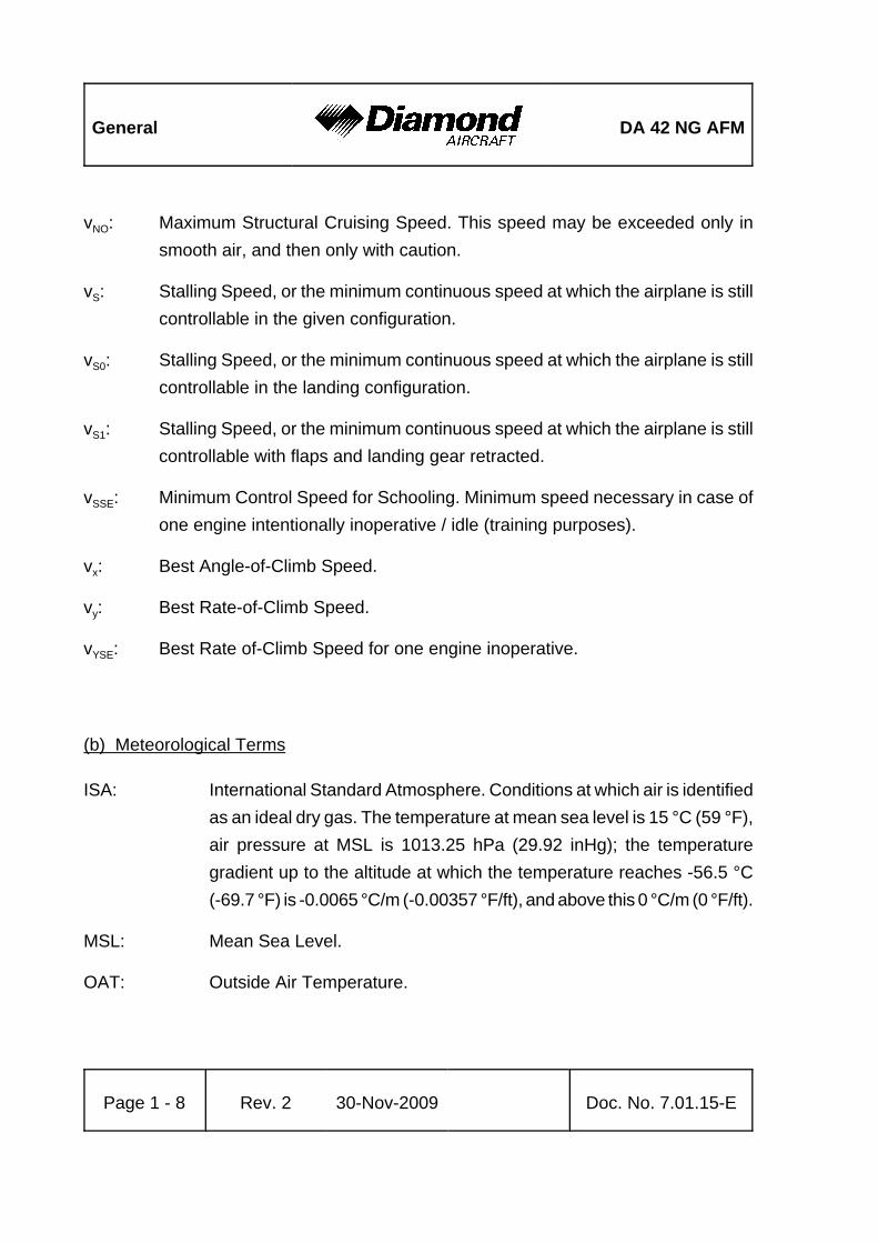
vNO: Maximum Structural Cruising Speed. This speed may be exceeded only insmooth air, and then only with caution.
vS: Stalling Speed, or the minimum continuous speed at which the airplane is stillcontrollable in the given configuration.
vS0: Stalling Speed, or the minimum continuous speed at which the airplane is stillcontrollable in the landing configuration.
vS1: Stalling Speed, or the minimum continuous speed at which the airplane is stillcontrollable with flaps and landing gear retracted.
vSSE: Minimum Control Speed for Schooling. Minimum speed necessary in case ofone engine intentionally inoperative / idle (training purposes).
vx: Best Angle-of-Climb Speed.
vy: Best Rate-of-Climb Speed.
vYSE: Best Rate of-Climb Speed for one engine inoperative.
(b) Meteorological Terms
ISA: International Standard Atmosphere. Conditions at which air is identifiedas an ideal dry gas. The temperature at mean sea level is 15 °C (59 °F),air pressure at MSL is 1013.25 hPa (29.92 inHg); the temperaturegradient up to the altitude at which the temperature reaches -56.5 °C(-69.7 °F) is -0.0065 °C/m (-0.00357 °F/ft), and above this 0 °C/m (0 °F/ft).
MSL: Mean Sea Level.
OAT: Outside Air Temperature.

DA 42 NG AFM General
Doc. No. 7.01.15-E Rev. 2 30-Nov-2009 Page 1 - 9
QNH: Theoretical atmospheric pressure at MSL, calculated from the elevationof the measuring point above MSL and the actual atmospheric pressureat the measuring point.
Density Altitude:Altitude in ISA conditions at which the air density is equal to the currentair density.
Indicated Pressure Altitude:Altitude reading with altimeter set to 1013.25 hPa (29.92 inHg).
Pressure Altitude:Altitude indicated by a barometric altimeter, which is set to 1013.25 hPa(29.92 inHg). The Pressure Altitude is the Indicated Pressure Altitudecorrected for installation and instrument errors.
In this Airplane Flight Manual altimeter instrument errors are regardedas zero.
Wind: The wind speeds which are shown as variables in the diagrams in thismanual should be regarded as headwind or tailwind components of themeasured wind.
(c) Flight Performance and Flight Planning
AGL: Above Ground Level.
Demonstrated Crosswind Component:The speed of the crosswind component at which adequate maneuverabil-ity for take-off and landing has been demonstrated during typecertification.

General DA 42 NG AFM
Page 1 - 10 Rev. 2 30-Nov-2009 Doc. No. 7.01.15-E
MET: Weather, weather advice.
NAV: Navigation, route planning.
RoC: Rate of Climb.
(d) Mass and Balance
CG: Center of Gravity, also called 'center of mass'. Imaginary point in whichthe airplane mass is assumed to be concentrated for mass and balancecalculations. Its distance from the Datum Plane is equal to the Centerof Gravity Moment Arm.
Center of Gravity Moment Arm:
The Moment Arm which is obtained if one divides the sum of the individualmoments of the airplane by its total mass.
Center of Gravity Limits:The Center of Gravity range within which the airplane, at a given mass,must be operated.
DP: Datum Plane; an imaginary vertical plane from which all horizontaldistances for center of gravity calculations are measured.
Empty Mass: The mass of the airplane including unusable fuel, all operating fluids andthe maximum quantity of oil.
Maximum Take-off Mass:The maximum permissible mass for take-off.

DA 42 NG AFM General
Doc. No. 7.01.15-E Rev. 2 30-Nov-2009 Page 1 - 11
Maximum Landing Mass:The highest mass for landing conditions at the maximum descent velocity.This velocity was used in the strength calculations to determine thelanding gear loads during a particularly hard landing.
Moment Arm: The horizontal distance from the Datum Plane to the Center of Gravityof a component.
Moment: The mass of a component multiplied by its moment arm.
Usable fuel: The quantity of fuel available for flight planning.
Unusable fuel: The quantity of fuel remaining in the tank which cannot be used for flight.
Useful load: The difference between take-off mass and empty mass.
(e) Engine
EECU: Electr. Engine Control Unit
RPM: Revolutions per minute (rotational speed of the propeller)
Engine starting fuel temperature:Above this fuel temperature the engine may be started.
Take-off fuel temperature:Above this fuel temperature take-off power setting is permitted.
OEI: One engine inoperative
General DA 42 NG AFM
Page 1 - 12 Rev. 2 30-Nov-2009 Doc. No. 7.01.15-E
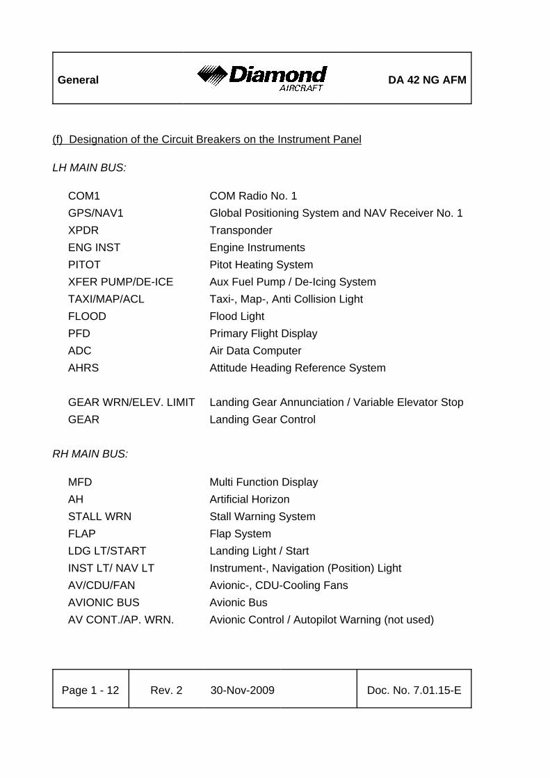
(f) Designation of the Circuit Breakers on the Instrument Panel
LH MAIN BUS:
COM1 COM Radio No. 1GPS/NAV1 Global Positioning System and NAV Receiver No. 1XPDR TransponderENG INST Engine InstrumentsPITOT Pitot Heating SystemXFER PUMP/DE-ICE Aux Fuel Pump / De-Icing SystemTAXI/MAP/ACL Taxi-, Map-, Anti Collision LightFLOOD Flood LightPFD Primary Flight DisplayADC Air Data ComputerAHRS Attitude Heading Reference System
GEAR WRN/ELEV. LIMIT Landing Gear Annunciation / Variable Elevator StopGEAR Landing Gear Control
RH MAIN BUS:
MFD Multi Function DisplayAH Artificial HorizonSTALL WRN Stall Warning SystemFLAP Flap SystemLDG LT/START Landing Light / StartINST LT/ NAV LT Instrument-, Navigation (Position) LightAV/CDU/FAN Avionic-, CDU-Cooling FansAVIONIC BUS Avionic BusAV CONT./AP. WRN. Avionic Control / Autopilot Warning (not used)

DA 42 NG AFM General
Doc. No. 7.01.15-E Rev. 2 30-Nov-2009 Page 1 - 13
AVIONICS BUS:
COM2 COM Radio No. 2GPS/NAV2 Global Positioning System and NAV Receiver No. 2AUDIO Audio PanelAUTO PILOT Auto Pilot SystemWx 500 StormscopeADF Automatic Direction FinderDME Distance Measuring EquipmentWx RDR Weather RadarTAS Traffic Advisory SystemDATA LINK GDL 69A Data Link System
LH ENG ECU BUS:
ECU BUS LH ECU BusECU B LH ECU BECU A LH ECU A
LH BUS:
ALT.LH LH AlternatorBATT Battery
LH ECU BUS:
ECU A LH ECU A (if installed)'
ECU B LH ECU B (if installed)'

General DA 42 NG AFM
Page 1 - 14 Rev. 2 30-Nov-2009 Doc. No. 7.01.15-E
FUEL PUMPS LH ENGINE:
FUEL PUMP A LH ECU A Fuel PumpFUEL PUMP B LH ECU B Fuel Pump
RH ENG ECU BUS:
ECU BUS RH ECU BusECU B RH ECU BECU A RH ECU A
RH BUS:
ALT.RH RH AlternatorBATT Battery
RH ECU BUS:
ECU A RH ECU A (if installed)'
ECU B RH ECU B (if installed)'
FUEL PUMPS RH ENGINE:
FUEL PUMP A RH ECU A Fuel PumpFUEL PUMP B RH ECU B Fuel Pump

DA 42 NG AFM General
Doc. No. 7.01.15-E Rev. 2 30-Nov-2009 Page 1 - 15
(g) Equipment
ELT: Emergency Locator Transmitter
(h) Design Change Advisories
MÄM: Mandatory Design Change AdvisoryOÄM: Optional Design Change AdvisoryVÄM: Variant Design Change Advisory
(i) Miscellaneous
ACG: Austro Control GmbH (Austrian Airworthiness Authority)ATC: Air Traffic ControlCFRP: Carbon Fiber Reinforced PlasticEASA: European Aviation Safety AgencyEPU: External Power UnitGIA: Garmin Integrated AvionicsGFRP: Glass Fiber Reinforced PlasticJAR: Joint Aviation RequirementsJC/VP: Joint Certification/Validation ProcedurePCA: Primary Certification Authority

General DA 42 NG AFM
Page 1 - 16 Rev. 2 30-Nov-2009 Doc. No. 7.01.15-E
1.6 UNITS OF MEASUREMENT
1.6.1 CONVERSION FACTORS
Dimension SI-Units US Units Conversion
Length [mm] millimeters
[m] meters
[km] kilometers
[in] inches
[ft] feet
[NM] nauticalmiles
[mm] / 25.4 = [in]
[m] / 0.3048 = [ft]
[km] / 1.852 = [NM]
Volume [l] liters [US gal] US gallons
[qts] US quarts
[l] / 3.7854 = [US gal]
[l] / 0.9464 = [qts]
Speed [km/h] kilometersper hour
[m/s] meters persecond
[kts] knots
[mph] miles perhour
[fpm] feet perminute
[km/h] / 1.852 = [kts]
[km/h] / 1.609 = [mph]
[m/s] x 196.85 = [fpm]
Speed ofrotation
[RPM] revolutions per minute --
Mass [kg] kilograms [lb] pounds [kg] x 2.2046 = [lb]
Force,weight
[N] newtons [lbf] poundsforce
[N] x 0.2248 = [lbf]
Pressure [hPa] hecto-pascals
[mbar] millibars
[bar] bars
[inHg] inches ofmercury
[psi] pounds persquare inch
[hPa] = [mbar]
[hPa] / 33.86 = [inHg]
[bar] x 14.504 = [psi]
Tempera-ture
[°C] degreesCelsius
[°F] degreesFahrenheit
[°C]x1.8 + 32 = [°F]
([°F] - 32)/1.8 = [°C]

DA 42 NG AFM General
Dimension SI-Units US Units Conversion
Doc. No. 7.01.15-E Rev. 2 30-Nov-2009 Page 1 - 17
Intensity ofelectriccurrent
[A] ampères --
Electriccharge(batterycapacity)
[Ah] ampère-hours
--
Electricpotential
[V] volts --
Time [sec] seconds --

General DA 42 NG AFM
Page 1 - 18 Rev. 2 30-Nov-2009 Doc. No. 7.01.15-E
1.6.2 CONVERSION CHART LITERS / US GALLONS
Liters US Gallons US Gallons Liters
5 1.3 1 3.8
10 2.6 2 7.6
15 4.0 4 15.1
20 5.3 6 22.7
25 6.6 8 30.3
30 7.9 10 37.9
35 9.2 12 45.4
40 10.6 14 53.0
45 11.9 16 60.6
50 13.2 18 68.1
60 15.9 20 75.7
70 18.5 22 83.3
80 21.1 24 90.9
90 23.8 26 98.4
100 26.4 28 106.0
110 29.1 30 113.6
120 31.7 32 121.1
130 34.3 34 128.7
140 37.0 36 136.3
150 39.6 38 143.8
160 42.3 40 151.4
170 44.9 45 170.3
180 47.6 50 189.3

DA 42 NG AFM General
Doc. No. 7.01.15-E Rev. 2 30-Nov-2009 Page 1 - 19
1.7 THREE-VIEW DRAWING

General DA 42 NG AFM
Page 1 - 20 Rev. 2 30-Nov-2009 Doc. No. 7.01.15-E
1.8 G1000 AVIONICS SYSTEM
1. The G1000 Integrated Avionics System is a fully integrated flight, engine,communication, navigation and surveillance instrumentation system. The systemconsists of a Primary Flight Display (PFD), Multi-Function Display (MFD), audio panel,Air Data Computer (ADC), Attitude and Heading Reference System (AHRS), enginesensors and processing unit (GEA), and integrated avionics (GIA) containing VHFcommunications, VHF navigation, and GPS (Global Positioning System).
2. The primary function of the PFD is to provide attitude, heading, air data, navigation,and alerting information to the pilot. The PFD may also be used for flight planning.The primary function of the MFD is to provide engine information, mapping, terraininformation, autopilot operation, and for flight planning. The audio panel is used forselection of radios for transmitting and listening, intercom functions, and marker beaconfunctions.
3. The primary function of the VHF Communication portion of the G1000 is to enableexternal radio communication. The primary function of the VOR/ILS Receiver portionof the equipment is to receive and demodulate VOR, Localizer, and Glide Slope signals.The primary function of the GPS portion of the system is to acquire signals from theGPS satellites, recover orbital data, make range and Doppler measurements, andprocess this information in real-time to obtain the user's position, velocity, and time.
4. Provided a Garmin G1000 GPS receiver is receiving adequate usable signals, it hasbeen demonstrated capable of and has been shown to meet the accuracy specificationsfor:
(a) VFR/IFR enroute, oceanic, terminal, and non-precision instrument approach (GPS,Loran-C, VOR, VOR-DME, TACAN, NDB, NDB-DME, RNAV) operation within theU.S. National Airspace System in accordance with AC 20-138A.

DA 42 NG AFM General
Doc. No. 7.01.15-E Rev. 2 30-Nov-2009 Page 1 - 21
(b) RNAV (GPS) Approaches - The G1000 GPS meets the requirements of AC20-138(A) for GPS based RNAV approaches. This includes RNAV approacheslabeled as RNAV (GPS), provided GPS sensor data is valid.
(c) The system meets the accuracy of RNP5 airspace (BRNAV) requirements ofAC 90-96 and in accordance with AC 20-138A, EASA AMC 20-4, and FAA Order8110.60 for oceanic and remote airspace operations, provided it is receiving usablenavigation information from the GPS receiver.
Navigation is accomplished using the WGS-84 (NAD-83) coordinate reference datum.GPS navigation data is based upon use of only the GPS operated by the United Statesof America.

General DA 42 NG AFM
Page 1 - 22 Rev. 2 30-Nov-2009 Doc. No. 7.01.15-E
1.9 SOURCE DOCUMENTATION
This section lists documents, manuals and other literature that were used as sources forthe Airplane Flight Manual, and indicates the respective publisher. However, only theinformation given in the Airplane Flight Manual is valid.
1.9.1 ENGINE
Address: Austro Engine GmbHRudolf Diesel-Str. 11 A-2700 Wiener NeustadtAUSTRIA
Phone: +43-2622-23 000 Fax: +43-2622-23 000 - 2711 Internet: www.austroengine.at
Documents: Operation Manual,E4.01.01 Rev. 1 or later
Engine TC-Holder: Diamond Aircraft Industries GmbHN.A. Otto-Straße 5A-2700 Wiener NeustadtAUSTRIA
DA 42 NG AFM General
Doc. No. 7.01.15-E Rev. 2 30-Nov-2009 Page 1 - 23
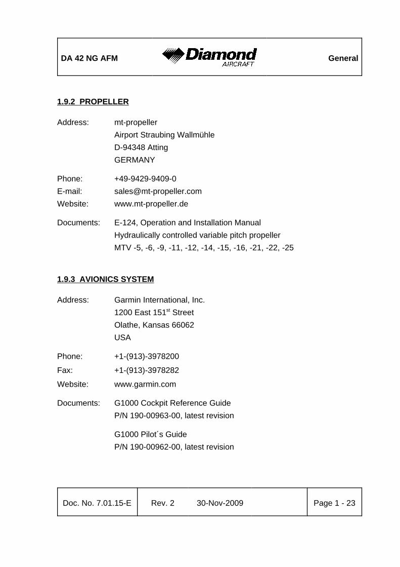
1.9.2 PROPELLER
Address: mt-propellerAirport Straubing WallmühleD-94348 AttingGERMANY
Phone: +49-9429-9409-0E-mail: [email protected]: www.mt-propeller.de
Documents: E-124, Operation and Installation ManualHydraulically controlled variable pitch propellerMTV -5, -6, -9, -11, -12, -14, -15, -16, -21, -22, -25
1.9.3 AVIONICS SYSTEM
Address: Garmin International, Inc.1200 East 151st StreetOlathe, Kansas 66062USA
Phone: +1-(913)-3978200
Fax: +1-(913)-3978282
Website: www.garmin.com
Documents: G1000 Cockpit Reference GuideP/N 190-00963-00, latest revision
G1000 Pilot´s GuideP/N 190-00962-00, latest revision

General DA 42 NG AFM
Page 1 - 24 Rev. 2 30-Nov-2009 Doc. No. 7.01.15-E
Intentionally left blank.

DA 42 NG AFM Operating Limitations
Doc. No. 7.01.15-E Rev. 2 30-Nov-2009EASA
approvedPage 2 - 1
CHAPTER 2OPERATING LIMITATIONS
Page
2.1 INTRODUCTION . . . . . . . . . . . . . . . . . . . . . . . . . . . . . . . . . . . . . . . 2-32.2 AIRSPEED . . . . . . . . . . . . . . . . . . . . . . . . . . . . . . . . . . . . . . . . . . . . 2-42.3 AIRSPEED INDICATOR MARKINGS . . . . . . . . . . . . . . . . . . . . . . . . 2-52.4 POWER-PLANT LIMITATIONS . . . . . . . . . . . . . . . . . . . . . . . . . . . . 2-62.5 ENGINE INSTRUMENT MARKINGS . . . . . . . . . . . . . . . . . . . . . . . 2-112.6 WARNING, CAUTION AND ADVISORY ALERTS . . . . . . . . . . . . . 2-12
2.6.1 WARNING, CAUTION AND ADVISORY ALERTS ON THE G1000. . . . . . . . . . . . . . . . . . . . . . . . . . . . . . . . . . . . . . . . . . . . . . . 2-12
2.6.2 OTHER WARNING ALERTS . . . . . . . . . . . . . . . . . . . . . . . . 2-152.7 MASS (WEIGHT) . . . . . . . . . . . . . . . . . . . . . . . . . . . . . . . . . . . . . . 2-162.8 CENTER OF GRAVITY . . . . . . . . . . . . . . . . . . . . . . . . . . . . . . . . . 2-182.9 APPROVED MANEUVERS . . . . . . . . . . . . . . . . . . . . . . . . . . . . . . 2-192.10 MANEUVERING LOAD FACTORS . . . . . . . . . . . . . . . . . . . . . . . . 2-202.11 OPERATING ALTITUDE . . . . . . . . . . . . . . . . . . . . . . . . . . . . . . . . 2-212.12 FLIGHT CREW . . . . . . . . . . . . . . . . . . . . . . . . . . . . . . . . . . . . . . . . 2-212.13 KINDS OF OPERATION . . . . . . . . . . . . . . . . . . . . . . . . . . . . . . . . . 2-212.14 FUEL . . . . . . . . . . . . . . . . . . . . . . . . . . . . . . . . . . . . . . . . . . . . . . . . 2-252.15 LIMITATION PLACARDS . . . . . . . . . . . . . . . . . . . . . . . . . . . . . . . . 2-262.16 OTHER LIMITATIONS . . . . . . . . . . . . . . . . . . . . . . . . . . . . . . . . . . 2-32
2.16.1 FUEL TEMPERATURE . . . . . . . . . . . . . . . . . . . . . . . . . . . . 2-322.16.2 BATTERY CHARGE . . . . . . . . . . . . . . . . . . . . . . . . . . . . . . 2-322.16.3 EMERGENCY SWITCH . . . . . . . . . . . . . . . . . . . . . . . . . . . 2-322.16.4 DOOR LOCKING DEVICE . . . . . . . . . . . . . . . . . . . . . . . . . 2-32

Operating Limitations DA 42 NG AFM
Page 2 - 2 Rev. 2 30-Nov-2009EASA
approvedDoc. No. 7.01.15-E
2.16.5 ELECTRONIC EQUIPMENT . . . . . . . . . . . . . . . . . . . . . . . 2-332.16.6 GARMIN G1000 AVIONICS SYSTEM . . . . . . . . . . . . . . . 2-342.16.7 AUTOPILOT LIMITATIONS . . . . . . . . . . . . . . . . . . . . . . . 2-382.16.8 SMOKING . . . . . . . . . . . . . . . . . . . . . . . . . . . . . . . . . . . . . 2-402.16.9 GROUND OPERATION . . . . . . . . . . . . . . . . . . . . . . . . . . 2-402.16.10 USE OF THE SUN VISORS . . . . . . . . . . . . . . . . . . . . . . 2-40

DA 42 NG AFM Operating Limitations
Doc. No. 7.01.15-E Rev. 2 30-Nov-2009EASA
approvedPage 2 - 3
2.1 INTRODUCTION
Chapter 2 of this Airplane Flight Manual provides operating limitations, instrument markingsand placards necessary for the safe operation of the airplane, its powerplants, standardsystems and standard equipment.
The limitations included in this Chapter are approved.
WARNINGOperation of the airplane outside of the approved operatinglimitations is not permissible.

Operating Limitations DA 42 NG AFM
Page 2 - 4 Rev. 2 30-Nov-2009EASA
approvedDoc. No. 7.01.15-E
2.2 AIRSPEED
Airspeed KIAS Remarks
vO Operatingmaneuveringspeed
above 1800 kg(3968 lb)
122 KIAS Do not make full orabrupt control surfacemovement above thisspeed.above 1700 kg
(3748 lb) to1800 kg (3968 lb)
119 KIAS
up to 1700 kg(3748 lb)
112 KIAS
vFE Max. flapsextended speed
LDG 113 KIAS Do not exceed thesespeeds with the givenflap setting.APP 133 KIAS
vLO Max. landinggear operatingspeed
Extension vLOE 188 KIAS Do not operate thelanding gear above thisspeed.Retraction vLOR 152 KIAS
vLE Max. landing gear extended speed 188 KIAS Do not exceed thisspeed with the landinggear extended.
vMCA Minimum control speed airborne 76 KIAS With one engineinoperative, keepairspeed above thislimit.
vNO Max. structural cruising speed 151 KIAS Do not exceed thisspeed except in smoothair, and then only withcaution.
vNE Never exceed speed in smooth air 188 KIAS Do not exceed thisspeed in any operation.

DA 42 NG AFM Operating Limitations
Doc. No. 7.01.15-E Rev. 2 30-Nov-2009EASA
approvedPage 2 - 5
2.3 AIRSPEED INDICATOR MARKINGS
Marking KIAS Significance
White arc 62 - 113 KIAS Operating range with flaps fully extended.
Green arc 69 - 151 KIAS Normal operating range.
Yellow arc 151 - 188 KIAS ‘Caution’ range - “Only in smooth air”.
Blue radial 85 KIAS Best rate of climb speed, single engine.
Red radial 76 KIAS Minimum control speed, single engine.
Red radial 188 KIAS Maximum speed for all operations - vNE.

Operating Limitations DA 42 NG AFM
Page 2 - 6 Rev. 2 30-Nov-2009EASA
approvedDoc. No. 7.01.15-E
2.4 POWER-PLANT LIMITATIONS
a) Number of engines : 2
b) Engine manufacturer : Austro Engine
c) Engine designation : E4-B
d) RPM limitations (shown as propeller RPM)Maximum take-off (rpm) : 2300 RPM max. 5 min.
Maximum continuous (rpm) : 2100 RPM
Maximum overspeed : 2500 RPM max. 20 sec
e) Engine powerMax. take-off power : 100% (123.5 kW) max. 5 min.
Max. continuous power : 92% (114 kW)
f) Oil pressure (absolute)Minimum < 1500 RPM : 1.5 bar
Minimum >= 1500 RPM : 2.5 bar
Maximum : 6.5 bar
Normal range : 2.5 bar - 6 bar

DA 42 NG AFM Operating Limitations
Doc. No. 7.01.15-E Rev. 2 30-Nov-2009EASA
approvedPage 2 - 7
g) Oil quantityMinimum : 5.0 l
Maximum : 7.0 l
Maximum oil consumption : 0.1 liters/hr
h) Oil temperatureMinimum : - 30 °C
Maximum : 140 °C
Normal range : 50 °C - 125 °C
i) Gearbox temperatureMinimum : - 30 °C
Minimum (full load) : 35 °C
Maximum : 120 °C
NOTEA cautionary (yellow) gearbox temperature range is notimposed by the engine manufacturer. However, there is adelay between power changes and gearbox temperature.Therefore, a cautionary range has been added to the G1000gearbox temperature instrument solely to make the pilotattentive to the gearbox temperature approaching themaximum allowable limit. There is no specific time limitassociated with operating in the cautionary gearboxtemperature range.

Operating Limitations DA 42 NG AFM
Page 2 - 8 Rev. 2 30-Nov-2009EASA
approvedDoc. No. 7.01.15-E
j) Coolant temperatureMinimum (at start-up) : - 30 °C
Minimum (full load) : 60 °C
Maximum : 105 °C
k) Fuel temperatureMinimum : - 25 °C
Maximum : 60 °C
l) Fuel pressureMinimum : 4 bar
Maximum : 7 bar
NOTEThe fuel pressure is not indicated on the G1000; a fuelpressure warning will illuminate on the PFD if the pressure'
is below limit.
m)VoltageMinimum : 24.1 V
Maximum : 32.0 V
n) AmperageMaximum : 70 A

DA 42 NG AFM Operating Limitations
Doc. No. 7.01.15-E Rev. 2 30-Nov-2009EASA
approvedPage 2 - 9
o) Propeller manufacturer : mt-Propeller
p) Propeller designation : MTV-6-R-C-F / CF 187-129
q) Propeller diameter : 187 cm
r) Prop. pitch angle (@ 0.75 R) : 12° ± 0.2° (low pitch)
15° ± 1° (start lock position)
81° ± 1° (feathered position)
s) Governor : mt-Propeller P-877-16 electrical governor withfeather position
t) Oil specification : SHELL HELIX ULTRA 5W30 SHELL HELIX ULTRA 5W40
u) Gearbox oil (propeller gearbox) : SHELL SPIRAX GSX 75W-80
v) Coolant : Distilled water / cooler protection (BASFGlysantin Protect Plus / G48) 1/1. The freezingpoint of the coolant is - 38°C.
CAUTIONIf the coolant or gearbox oil level is low the reason must bedetermined and the problem must be corrected by authorizedpersonnel.
w) Maximum restart altitude : 18,000 ft pressure altitude for immediate restarts
10,000 ft pressure altitude for restarts within two minutes

Operating Limitations DA 42 NG AFM
Page 2 - 10 Rev. 2 30-Nov-2009EASA
approvedDoc. No. 7.01.15-E
x) Restart airspeed (starter) : max. 100 KIAS or airspeed for a stationarypropeller, whichever is lower
Restart airspeed (windmilling) : 125 KIAS to 145 KIAS
y) No intentional shutdown below 3,000 ft AGL and above 10,000 ft pressure altitude.'

DA 42 NG AFM Operating Limitations
Doc. No. 7.01.15-E Rev. 2 30-Nov-2009EASA
approvedPage 2 - 11
2.5 ENGINE INSTRUMENT MARKINGS
Engine instrument markings and their color code significance are shown in the tablesbelow.
Indi-cation
Redarc/bar
=lower
prohibitedrange
Yellowarc/bar
=cautionrange
Greenarc/bar
=normal
operatingrange
Yellowarc/bar
=cautionrange
Redarc/bar
=upper
prohibitedrange
RPM -- --up to
2100 RPM2100 to
2300 RPMabove
2300 RPM
Oilpressure below 1.5 bar 1.5 to 2.5 bar 2.5 to 6.0 bar 6.0 to 6.5 bar above 6.5 bar
Oiltemp. below -30°C -30° to 50°C 50° to 125°C
125° to140°C
above 140°C
Coolanttemp. below -30°C -30° to 60°C 60° to 95°C 95° to 105°C above 105°C
Gearboxtemp. below -30°C -30° to 35°C 35° to 115°C
115° to120°C
above 120°C
Load -- -- up to 92% 92 - 100% --
Fueltemp. below -25°C -25° to 5°C 5° to 55°C 55° to 60°C above 60°C
Ammeter -- -- up to 60A 60 to 70A above 70A
Volt-meter below 24.1V 24.1 to 25V 25 to 30V 30 to 32V above 32V
Fuel qty. below1 US gal
--1 to 25US gal
-- --

Operating Limitations DA 42 NG AFM
Page 2 - 12 Rev. 2 30-Nov-2009EASA
approvedDoc. No. 7.01.15-E
2.6 WARNING, CAUTION AND ADVISORY ALERTS
2.6.1 WARNING, CAUTION AND ADVISORY ALERTS ON THE G1000
NOTEThe alerts described in the following are displayed on theGarmin G1000. Section 7.10 includes a detailed descriptionof the alerts.
The following tables show the color and significance of the warning, caution and advisoryalerts lights on the G1000.
Color and Significance of the Warning Alerts on the G1000
Warning alerts (red)
Meaning / Cause
WARNING One of the warnings listed below is being indicated.
L/R ENG TEMP Left / Right engine coolant temperature is in the upper redrange (too high / >105 °C).
L/R OIL TEMP Left / Right engine oil temperature is in the upper red range(too high / >140 °C).
L/R OIL PRES Left / Right engine oil pressure is in the lower red range (too low / <1.5 bar).
L/R FUEL TEMP Left / Right fuel temperature is in the upper red range (toohigh / >60 °C)
L/R GBOX TEMP Left / Right engine gearbox temperature is in the upper redrange (too high / >120 °C).
L/R FUEL PRESS Left / Right engine fuel pressure is low.

DA 42 NG AFM Operating Limitations
Warning alerts (red)
Meaning / Cause
Doc. No. 7.01.15-E Rev. 2 30-Nov-2009EASA
approvedPage 2 - 13
L/R ALTN AMPS Left / Right engine alternator output is in the upper red range(too high / >70 amps).
L/R ENG FIRE Left / Right engine fire detected.
L/R STARTER Left / Right engine starter is engaged.
DOOR OPEN Front and/or rear canopy and/or baggage door are/is notclosed and locked.
ATTITUDE FAIL The display system is not receiving attitude referenceinformation from the AHRS.
AIRSPEED FAIL The display system is not receiving airspeed input from theair data computer.
ALTITUDE FAIL The display system is not receiving altitude input from the airdata computer.
VERT SPEEDFAIL
The display system is not receiving vertical speed input fromthe air data computer.
HDG The display system is not receiving valid heading input fromthe AHRS.
WARN RAIM position warning. The nav deviation bar is removed.
Red X' A red X through any display field, such as com frequencies,'
nav frequencies, or engine data, indicates that the display'
field is not receiving valid data.'

Operating Limitations DA 42 NG AFM
Page 2 - 14 Rev. 2 30-Nov-2009EASA
approvedDoc. No. 7.01.15-E
Color and Significance of the Caution Alerts on the G1000
Caution alerts(amber)
Meaning / Cause
L/R ECU A FAIL
A fault has occurred in the left/right engine ECU A (one resetof minor faults is possible)
or
ECU A is being tested during FADEC-test procedure duringthe 'Before Take-Off Check'.
L/R ECU B FAIL
A fault has occurred in the left/right engine ECU B (one resetof minor faults is possible)
or
ECU B is being tested during FADEC-test procedure duringthe 'Before Take-Off Check'.
L/R FUEL LOW Left / Right main tank fuel quantity is low.
L/R ALTN FAIL Left / Right engine alternator has failed.
L/R VOLTS LOW Left / Right engine bus voltage is too low (< 25 volts).
L/R COOL LVL Left / Right engine coolant level is low.
PITOT FAIL Pitot heat has failed.
PITOT HT OFF Pitot heat is OFF.
STAL HT FAIL Stall warning heat has failed.
STAL HT OFF Stall warning heat is OFF.
STICK LIMIT Control stick limiting system (variable elevator stop) hasfailed.
LOI' GPS integrity is insufficient for the current phase of flight.'
AHRS ALIGN:Keep Wings Level
The AHRS (Attitude and Heading Reference System) isaligning.
L/R AUX FUEL E Left / Right auxiliary fuel tank empty (if installed).

DA 42 NG AFM Operating Limitations
Caution alerts(amber)
Meaning / Cause
Doc. No. 7.01.15-E Rev. 2 30-Nov-2009EASA
approvedPage 2 - 15
CHECK GEAR Landing gear is not down and locked.
DEICE LVL LO De-icing fluid level is low (if installed).
DEIC PRES HI De-icing pressure is high (if installed).
DEIC PRES LO De-icing pressure is low (if installed).
Color and Significance of the Advisory Alerts on the G1000
Advisory alerts(white)
Meaning / Cause
L/R GLOW ON Left / Right engine glow plug active.
L/R AUXPUMPON
Fuel transfer from auxiliary to main tank is in progress (ifinstalled).
PFD FAN FAIL Cooling fan for the PFD is inoperative.
MFD FAN FAIL Cooling fan for the MFD is inoperative.
GIA FAN FAIL Cooling fan for the GIAs is inoperative.
2.6.2 OTHER WARNING ALERTS
Warning Alerts on the Instrument Panel
Warning alert(red)
Meaning / Cause
GEAR UNSAFEWARNING LIGHT
Illuminates if the landing gear is neither in the final up nor inthe down & locked position.

Operating Limitations DA 42 NG AFM
Page 2 - 16 Rev. 2 30-Nov-2009EASA
approvedDoc. No. 7.01.15-E
Audible Warning Alerts
Audible warningalert
Meaning / Cause
GEARRETRACTEDCHIME TONE(repeating)
Resounds if the landing gear is retracted while the flaps moveinto position LDG or when the power lever is placed in aposition below 25%.
2.7 MASS (WEIGHT)
Value Mass (Weight)
Minimum flight mass 1510 kg 3329 lbMaximum take-off mass 1900 kg 4189 lbMaximum zero fuel mass 1765 kg 3891 lbMaximum landing mass (see NOTE below) 1805 kg 3979 lbMax. load in nose baggage compartment(in fuselage nose)
30 kg 66 lb
Max. load in cabin baggage compartment(behind rear seats)
45 kg 100 lb
Max. load in baggage extension(behind cabin baggage compartment)
18 kg 40 lb
Max. load, cabin baggage compartment and baggageextension together
45 kg 100 lb
WARNINGExceeding the mass limits will lead to overstressing of theairplane as well as to degradation of flight characteristics andflight performance.

DA 42 NG AFM Operating Limitations
Doc. No. 7.01.15-E Rev. 2 30-Nov-2009EASA
approvedPage 2 - 17
NOTEIn some countries the beginning of a flight is defined bystarting the powerplant. In those countries a ramp mass ofmaximal MTOM + 8 kg (MTOM + 18 lb) is approved. At thetime of lift-off the maximum permitted take-off mass must notbe exceeded.
NOTEA landing with a mass between 1805 kg (3979 lb) and1900 kg (4189 lb) is admissible. It constitutes an abnormaloperating procedure. A "Hard Landing Check" is only requiredafter a hard landing, regardless of the actual landing mass.

Operating Limitations DA 42 NG AFM
Page 2 - 18 Rev. 2 30-Nov-2009EASA
approvedDoc. No. 7.01.15-E
2.8 CENTER OF GRAVITY
Datum Plane
The datum plane (DP) is a plane which is normal to the airplane’s longitudinal axis andin front of the airplane as seen from the direction of flight. The airplane’s longitudinal axisis parallel with the floor of the nose baggage compartment. When the floor of the nosebaggage compartment is aligned horizontally, the datum plane is vertical. The datum planeis located 2.196 meters (86.46 in) forward of the most forward point of the root rib on thestub wing (refer to figure in Section 6.2).
Center of Gravity Limitations
The center of gravity (CG position) for flight conditions must be between the followinglimits:
Most forward flight CG:
2.357 m (92.80 in) aft of datum plane at 1510 kg (3329 lb)2.418 m (95.20 in) aft of datum plane at max. take-off mass (see Section 2.7)linear variation in between
Most rearward flight CG:
2.460 m (96.85 in) aft of datum plane at 1510 kg (3329 lb)2.480 m (97.64 in) aft of datum plane at 1700 kg (3748 lb)2.480 m (97.64 in) aft of datum plane at max. take-off mass (see Section 2.7)linear variation in between
Refer to Section 6.4.4 for a graphical illustration of the CG limitations.
WARNINGExceeding the center of gravity limitations reduces thecontrollability and stability of the airplane.

DA 42 NG AFM Operating Limitations
Doc. No. 7.01.15-E Rev. 2 30-Nov-2009EASA
approvedPage 2 - 19
2.9 APPROVED MANEUVERS
The airplane is certified in the Normal Category in accordance with JAR-23.
Approved Maneuvers
1) all normal flight maneuvers;
2) stalling (with the exception of dynamic stalling); and
3) Lazy Eights, Chandelles, as well as steep turns and similar maneuvers, in whichan angle of bank of not more than 60° is attained.
CAUTIONAerobatics, spinning and flight maneuvers with more than 60°of bank are not permitted in the Normal Category. Stallingwith asymmetric power or one engine inoperative is notpermitted.
CAUTIONIntentional negative g- maneuvers are not permitted.

Operating Limitations DA 42 NG AFM
Page 2 - 20 Rev. 2 30-Nov-2009EASA
approvedDoc. No. 7.01.15-E
2.10 MANEUVERING LOAD FACTORS
NOTEThe tables below show structural limitations. The load factorlimits for the engine must also be observed. Refer to thecorresponding Operation Manual for the engine.
at vO at vNE with flaps in APPor LDG position
Positive 3.8 3.8 2.0
Negative -1.52 -1.52
WARNINGExceeding the maximum structural load factors will lead tooverstressing of the airplane.
CAUTIONIntentional negative g- maneuvers are not permitted.

DA 42 NG AFM Operating Limitations
Doc. No. 7.01.15-E Rev. 2 30-Nov-2009EASA
approvedPage 2 - 21
2.11 OPERATING ALTITUDE
The maximum operating altitude is 18,000 ft (5,486 m) pressure altitude.
2.12 FLIGHT CREW
Minimum crew : 1 (one person)
Maximum number of occupants : 4 (four persons)
2.13 KINDS OF OPERATION
Provided that national operational requirements are met, the following kinds of operationare approved:
• daytime flights according to Visual Flight Rules (VFR)
• with the appropriate equipment: night flights according to Visual Flight Rules (NVFR)
• with the appropriate equipment: flights according to Instrument Flight Rules (IFR)
• take-off and landing on paved surfaces
• take-off and landing on grass surfaces
Flights into known or forecast thunderstorms are prohibited.
Minimum Operational Equipment (Serviceable)
The following table lists the minimum serviceable equipment required by JAR-23. Additionalminimum equipment for the intended operation may be required by national operatingrules and also depends on the route to be flown.

Operating Limitations DA 42 NG AFM
Page 2 - 22 Rev. 2 30-Nov-2009EASA
approvedDoc. No. 7.01.15-E
NOTEMany of the items of minimum equipment listed in thefollowing table are integrated in the G1000.
for daytime VFR flights
in addition for night VFR flights
in addition for IFR flights
Flight &navigationinstruments
* airspeed indicator(on G1000 PFD orbackup)
* altimeter (on G1000PFD or backup)
* magnetic compass
* 1 headset, used bypilot in command
* vertical speedindicator (VSI)
* attitude gyro(artificial horizon; onG1000 PFD orbackup)
* turn & bankindicator (on G1000PFD)
* directional gyro
* VHF radio (COM)with speaker andmicrophone
* VOR receiver
* transponder(XPDR), mode Aand mode C
* GPS receiver (partof G1000)
* second airspeedindicator (both, onG1000 PFD andbackup)
* second altimeter(both, on G1000PFD and backup)
* second attitudegyro (both, onG1000 PFD andbackup)
* second VHF radio(COM)
* VOR-LOC-GPreceiver
* second GPSreceiver (part ofG1000)

DA 42 NG AFM Operating Limitations
for daytime VFR flights
in addition for night VFR flights
in addition for IFR flights
Doc. No. 7.01.15-E Rev. 2 30-Nov-2009EASA
approvedPage 2 - 23
Engineinstruments
* fuel qty. (2x)
* oil press. (2x)
* oil temp. (2x)
* coolant temp. (2x)
* coolant levelindicator (2x)
* gearbox temp. (2x)
* load (2x)
* prop. RPM (2x)
* fuel temp. left &right tank
* fuel flow (2x) * fuel px warning
* ammeter
* voltmeter
Lighting * position lights
* strobe lights (anticollision lights)
* landing light
* instrument lighting
* flood light
* flashlight

Operating Limitations DA 42 NG AFM
for daytime VFR flights
in addition for night VFR flights
in addition for IFR flights
Page 2 - 24 Rev. 2 30-Nov-2009EASA
approvedDoc. No. 7.01.15-E
Otheroperationalminimumequipment
* stall warningsystem
* variable elevatorstop
* alternate means forfuel quantityindication (seeSection 7.9)
* safety belts for eachoccupied seat
* Airplane FlightManual
* Pitot heatingsystem
* alternate staticvalve
* emergency battery(for backup attitudegyro and flood light)
NOTEA list of approved equipment can be found in Chapter 6.
Engine Systems and Equipment
All engine systems and equipment must be functional prior to airplane take-off. Any enginesystem or equipment failure must be corrected before next flight.
DA 42 NG AFM Operating Limitations
Doc. No. 7.01.15-E Rev. 2 30-Nov-2009EASA
approvedPage 2 - 25
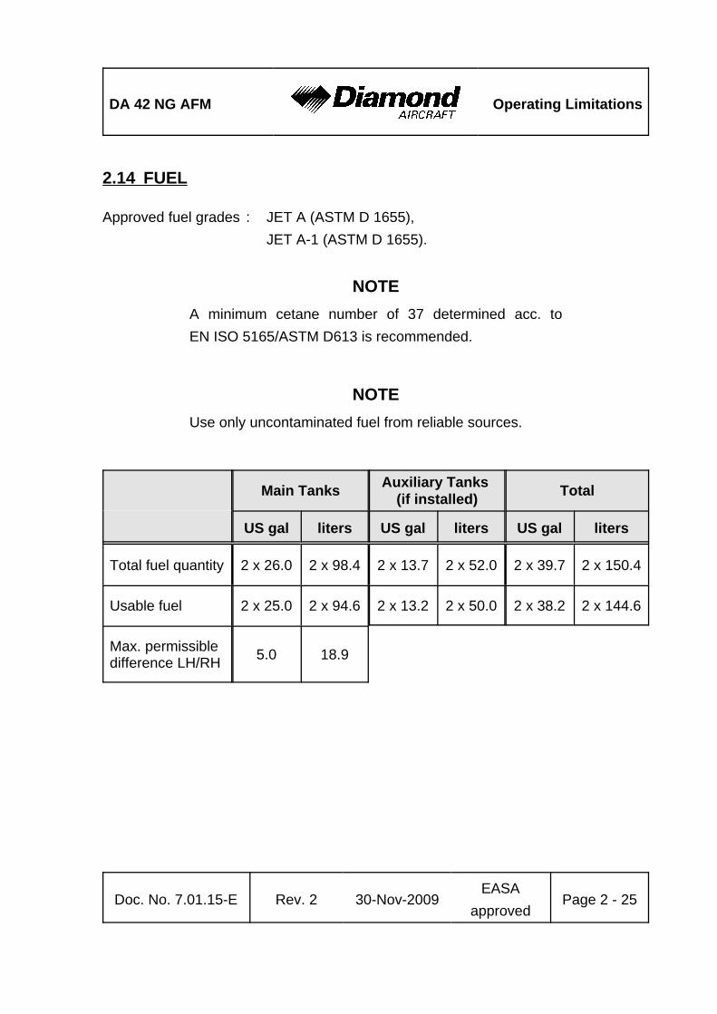
2.14 FUEL
Approved fuel grades : JET A (ASTM D 1655),JET A-1 (ASTM D 1655).
NOTEA minimum cetane number of 37 determined acc. toEN ISO 5165/ASTM D613 is recommended.
NOTEUse only uncontaminated fuel from reliable sources.
Main Tanks Auxiliary Tanks (if installed) Total
US gal liters US gal liters US gal liters
Total fuel quantity 2 x 26.0 2 x 98.4 2 x 13.7 2 x 52.0 2 x 39.7 2 x 150.4
Usable fuel 2 x 25.0 2 x 94.6 2 x 13.2 2 x 50.0 2 x 38.2 2 x 144.6
Max. permissibledifference LH/RH 5.0 18.9

Operating Limitations DA 42 NG AFM
Page 2 - 26 Rev. 2 30-Nov-2009EASA
approvedDoc. No. 7.01.15-E
2.15 LIMITATION PLACARDS
All limitation placards are shown below. A list of all placards is included in the AirplaneMaintenance Manual (Doc. No. 7.02.15), Chapter 11.
The following limitation placards are in the forward view of the pilot:
Limitations for GFC 700 Autopilot System:Autopilot / Yaw Damper DISC during take-off and landing.
Do not use AP during single engine operation.
Maximum speed for autopilot operation is 180 KIAS.
Minimum speed for autopilot operation is 90 KIAS.
Minimum Altitude for Autopilot Operation:
Cruise, Climb, Descent and Maneuvering: 800 feet AGL
Approach : 200 feet AGL
Departure : 200 feet AGL
This airplane may only be operated in accordance with the Airplane'Flight Manual in the "Normal" category. Provided that national'operational requirements are met and the appropriate equipment is'installed and operational, this airplane is approved for the following'kinds of operation: day VFR, night VFR, IFR and flight into known or'forecast icing conditions. All aerobatic maneuvers including spinning'are prohibited. For further operational limitations refer to the Airplane'Flight Manual.'
Operating maneuvering speed:'vO = 122 KIAS (above 1800 kg / 3968 lb)'vO = 119 KIAS (above 1700 kg / 3748 lb to 1800 kg / 3968 lb)'vO = 112 KIAS (up to 1700 kg / 3748 lb )'

DA 42 NG AFM Operating Limitations
Doc. No. 7.01.15-E Rev. 2 30-Nov-2009EASA
approvedPage 2 - 27
GPS NOT APPROVEDFOR WAAS OPERATIONS
LANDING GEARvLE / vLOE = 188 KIAS
vLOR = 152 KIAS
EMERGENCY
Gear Extension
Max. 152 KIAS
max. usablefuel: 2 x 25 US galmax. difference LH/RH
tank: 5 US gal
max. usable fuel main tank:
2 x 25 US galauxiliary tank:2 x 13 US gal
max. difference LH/RHmain tank: 5 US gal
On the Emergency Landing Gear Extension Lever:
On the Instrument Panel:
Standard Tank: Auxiliary Tank (if installed):

Operating Limitations DA 42 NG AFM
Page 2 - 28 Rev. 2 30-Nov-2009EASA
approvedDoc. No. 7.01.15-E
Crossfeedwith fuelpump ON inemergenciesonly
WARNINGAPPROVED FUEL
JET-A1or see Airplane Flight Manual
Next to the Fuel Selector:
(a) Next to Each of the Two Fuel Filler Necks;(b) In Addition Next to Each of the Two Auxiliary Fuel Filler Necks (if installed):

DA 42 NG AFM Operating Limitations
Doc. No. 7.01.15-E Rev. 2 30-Nov-2009EASA
approvedPage 2 - 29
OILSHELL HELIX
ULTRA
5W30or see Airplane Flight Manual
In Each Cowling, on the Door for the Oil Filler Neck:
Next to the Flap Selector Switch:
UP
Flaps
APP133 KIAS
LDG 113 KIAS

Operating Limitations DA 42 NG AFM
Page 2 - 30 Rev. 2 30-Nov-2009EASA
approvedDoc. No. 7.01.15-E
Next to the Cabin Baggage Compartment:'
In the Cabin, on the Left Fuselage Sidewall:'

DA 42 NG AFM Operating Limitations
Doc. No. 7.01.15-E Rev. 2 30-Nov-2009EASA
approvedPage 2 - 31
In the Nose Baggage Compartment:
Beside the Door Locking Device Installed in the Passengers' Door:
On the Right-Hand Side of the Instrument Panel Above the Circuit Breakers:
Max. Baggage:
30 kg [66 lb]
EMERGENCY EXIT:The keylock must beunlocked during flight
______ NO SMOKING ______

Operating Limitations DA 42 NG AFM
Page 2 - 32 Rev. 2 30-Nov-2009EASA
approvedDoc. No. 7.01.15-E
2.16 OTHER LIMITATIONS
2.16.1 FUEL TEMPERATURE
From -25 °C to 60 °C (from -13 °F to 140 °F).
2.16.2 BATTERY CHARGE
Taking off for a Night VFR or IFR flight with an empty battery is not permitted.
The use of an external power supply for engine starting with an empty airplane batteryis also not permitted if the subsequent flight is intended to be a Night VFR or IFR flight.In this case the airplane battery must first be charged.
2.16.3 EMERGENCY SWITCH
IFR flights are not permitted when the seal on the emergency switch is broken.
2.16.4 DOOR LOCKING DEVICE
The canopy and the passenger door must not be blocked by the key lock during operationof the airplane.

DA 42 NG AFM Operating Limitations
Doc. No. 7.01.15-E Rev. 2 30-Nov-2009EASA
approvedPage 2 - 33
2.16.5 ELECTRONIC EQUIPMENT
The use and switching on of electronic equipment other than that which is part of theequipment of the airplane is not permitted, as it could lead to interference with theairplane's avionics.
Examples of undesirable items of equipment are:
- Mobile phones- Remote radio controls- Video screens employing CRTs- Minidisc recorders in record mode
This list is not exhaustive.
The use of laptop computers, including those with CD-ROM drives, CD and minidiscplayers in the replay mode, cassette players and video cameras is permitted. All thisequipment however should be switched off for take-off and landing.

Operating Limitations DA 42 NG AFM
Page 2 - 34 Rev. 2 30-Nov-2009EASA
approvedDoc. No. 7.01.15-E
2.16.6 GARMIN G1000 AVIONICS SYSTEM
1. The Garmin G1000 Cockpit Reference Guide, P/N 190-00963-00, appropriaterevision must be immediately available to the flight crew.
2. The G1000 must utilize the software Garmin 010-00670-01 approved software inaccordance with the mandatory service bulletin DAI MSB 42NG-003, latest version.
Software Part Number Approved
Version
Function
System
for a
ppro
ved
vers
ion
see
DA
I MS
B 4
2NG
-003
late
st v
ersi
on
010-00670-01Manifest006-B0093-( ) GPS1, GPS2006-B0172-( ) GTX1-GIA1, GTX1-GIA2006-B0190-( ) GIA1, GIA2006-B0193-( ) GEA1-GIA1; GEA1-GIA2006-B0203-( ) GMA1-GIA1, GMA1-GAI2006-B0223-( ) GRS1-GIA1, GRS1-GIA2006-B0224-( ) GMU1006-B0319-( ) PFD1, MFD1006-B0328-( )006-B0329-( )006-C0048-( ) GMU1 FPGA006-C0049-( ) GRS1 FPGA006-C0055-( ) GDC1 FPGA006-D0159-( ) GRS1 MV DB006-D0202-( )006-B0261-( ) GDC1-GIA1006-B0081-( ) COM1, COM2006-B0083-( ) GS1, GS2006-B0082-( ) NAV1, NAV2

DA 42 NG AFM Operating Limitations
Doc. No. 7.01.15-E Rev. 2 30-Nov-2009EASA
approvedPage 2 - 35
NOTEThe database version is displayed on the MFD power-up pageimmediately after system power-up and must beacknowledged. The remaining system software versions canbe verified on the AUX group sub-page 5, "AUX-SYSTEMSTATUS".
3. IFR enroute, oceanic and terminal navigation predicated upon the G1000 GPS Receiveris prohibited unless the pilot verifies the currency of the database or verifies eachselected way point for accuracy by reference to current approved data.
4. Instrument approach navigation predicated upon the G1000 GPS Receiver must beaccomplished in accordance with approved instrument approach procedures that areretrieved from the GPS equipment database. The GPS equipment database mustincorporate the current update cycle.
NOTENot all published approaches are in the FMS database. Thepilot must ensure that the planned approach is in thedatabase.
(a) Instrument approaches utilizing the GPS receiver must be conducted in theapproach mode and Receiver Autonomous Integrity Monitoring (RAIM) mustbe available at the Final Approach Fix.
(b) Accomplishment of ILS, LOC, LOC-BC, LDA, SDF, MLS or any other type ofapproach not approved for GPS overlay with the G1000 GPS receiver is notauthorized.
(c) Use of the G1000 VOR/ILS receiver to fly approaches not approved for GPSrequire VOR/ILS navigation data to be present on the display.

Operating Limitations DA 42 NG AFM
Page 2 - 36 Rev. 2 30-Nov-2009EASA
approvedDoc. No. 7.01.15-E
(d) When an alternate airport is required by the applicable operating rules, it mustbe served by an approach based on other than GPS or Loran-C navigation,the airplane must have the operational equipment capable of using thatnavigation aid, and the required navigation aid must be operational.
(e) VNAV information may be utilized for advisory information only. Use of VNAVinformation for Instrument Approach Procedures does not guarantee step-downfix altitude protection, or arrival at approach minimums in normal position to land.
(f) RNAV (GPS) approaches must be conducted utilizing the GPS sensor.
(g) RNP RNAV operations are not authorized, except as noted in Chapter 1 of thisAFM.
5. If not previously defined, the following default settings must be made in the "SYSTEMSETUP" menu of the G1000 prior to operation (refer to Pilot's Guide for procedureif necessary):
(a) DIS, SPD : nm, kt (sets navigation units to "nautical miles" and "knots")
(b) ALT, VS : ft, fpm (sets altitude units to "feet" and "feet per minute")
(c) POSITION : deg-min (sets navigation grid units to decimal minutes)
NOTENavigation Information is referenced to WGS-84 referencesystem, and should only be used where the AeronauticalInformation Publication (including electronic data andaeronautical charts) conforms to WGS-84 or equivalent.

DA 42 NG AFM Operating Limitations
Doc. No. 7.01.15-E Rev. 2 30-Nov-2009EASA
approvedPage 2 - 37
6. When AHRS is required to meet the items listed in the minimum operational equipment(serviceable) table in Section 2.13 of this AFM, operation is prohibited in the followingareas:
(a) North of 72° N latitude at all longitudes.'
(b) South of 70° S latitude at all longitudes.'
(c) North of 65° N latitude between longitude 75° W and 120° W (Northern Canada).'
(d) North of 70° N latitude between longitude 70° W and 128° W (Northern Canada).'
(e) North of 70° N latitude between longitude 85° E and 114° E (Northern Russia).'
(f) South of 55° S latitude between longitude 120° E and 165° E (Region south'
of Australia and New Zealand).'
When day VFR operations are conducted in the above areas, the MFD must be ina non-heading up orientation.
7. The fuel quantity, fuel required, and fuel remaining functions on the Fuel Page(displayed when pushing the FUEL button as shown in Section 7.13) of the FMS aresupplemental information only and must be verified by the flight crew.
8. The GPS is not approved for WAAS operations:
(a) The G1000 integrated avionics system is NOT approved for GPS WAASoperations including GPS WAAS approach procedures such as "LPV","LNAV/VNAV", and "LNAV +V".
(b) SBAS (WAAS & MSAS) functionality must be disabled on the G 1000 GPSStatus page (refer to the G1000 Pilot´s Guide for procedure).
9. The availability of SafeTaxi®, ChartView, or FliteCharts® in electronic form on the G1000is for information purposes only, it is still mandatory to carry another source of chartson-board the airplane.

Operating Limitations DA 42 NG AFM
Page 2 - 38 Rev. 2 30-Nov-2009EASA
approvedDoc. No. 7.01.15-E
2.16.7 AUTOPILOT LIMITATIONS
1. It is the responsibility of the pilot in command to monitor the autopilot when it isengaged. The pilot should be prepared to immediately disconnect the autopilot andto take prompt corrective action in the event of unexpected or unusual autopilotbehavior.
2. The autopilot and yaw damper must be disconnected (using the DISC button) duringtake-off, landing and single engine operation.
3. Following an autopilot or electric trim malfunction, reengaging the autopilot or manualelectric trim, or resetting the AUTOPILOT circuit breaker is prohibited until the causeof the malfunction has been determined and corrected.
4. The Garmin G1000 Cockpit Reference Guide for the Diamond DA 42 NG,P/N 010-00963-00 approved revision must be immediately available to the flight crew.
5. ILS approaches using the GFC700 / flight director are limited to Category I approachesonly.
6. Autopilot maximum airspeed: 180 KIASAutopilot minimum airspeed: 90 KIAS
7. Altitude select captures below 1200 feet AGL are prohibited.
8. The autopilot must be disengaged:- below 200 ft AGL during approach,- below 200 ft AGL during departure,- below 800 ft AGL for all other phases of flight,- during single engine operation.
9. Overriding the autopilot to change pitch or roll attitude is prohibited. (Disengage orpress CWS while maneuvering.)

DA 42 NG AFM Operating Limitations
Doc. No. 7.01.15-E Rev. 2 30-Nov-2009EASA
approvedPage 2 - 39
10. The GFC 700 components must utilize the following or later approved softwareversions:
Sub-System Software Version
GDU v9.03
GDC 74 v3.02
GEA 7X v2.07
GPS v3.03
GIA 6X v5.65
GIA Audio v2.03
GMAX347 v4.01
GMU44 v2.01
GRS 77 v2.11
GTX 33X v5.01
GDL 69 v3.20.00
GSA 8X v2.20
GFC 700 v2.00
The system software versions can be verified on the AUX group sub-page 5, "AUX -SYSTEM STATUS".

Operating Limitations DA 42 NG AFM
Page 2 - 40 Rev. 2 30-Nov-2009EASA
approvedDoc. No. 7.01.15-E
11. The GFC 700 AFCS pre-flight test must be successfully completed prior to useof the autopilot, flight director, yaw damper or manual electric trim.
12. A pilot with the seat belt fastened must occupy the left pilot's seat during alloperations.
13. The yaw damper is an integral part of the autopilot system and must not be usedseparately.
2.16.8 SMOKING
Smoking in the airplane is not permitted.
2.16.9 GROUND OPERATION
Take-off and landing has been demonstrated on hard paved surfaces (asphalt, concrete,etc.) and grass runways.
2.16.10 USE OF THE SUN VISORS
The sun visors (if installed, OÄM 42-101 or OÄM 42-142) may only be used during cruise.'
During all other phases of flight the sun visors must be locked in the fully upward position.

DA 42 NG AFMEmergencyProcedures
Doc. No. 7.01.15-E Rev. 2 30-Nov-2009 Page 3 - 1
CHAPTER 3EMERGENCY PROCEDURES
Page
3.1 INTRODUCTION . . . . . . . . . . . . . . . . . . . . . . . . . . . . . . . . . . . . . . . 3-43.1.1 GENERAL . . . . . . . . . . . . . . . . . . . . . . . . . . . . . . . . . . . . . . . . 3-43.1.2 CERTAIN AIRSPEEDS IN EMERGENCIES . . . . . . . . . . . . . . 3-53.1.3 SELECTING EMERGENCY FREQUENCY . . . . . . . . . . . . . . 3-5
3.2 AIRPLANE-RELATED G1000 WARNINGS . . . . . . . . . . . . . . . . . . . 3-63.2.1 WARNINGS / GENERAL . . . . . . . . . . . . . . . . . . . . . . . . . . . . 3-63.2.2 L/R ENG TEMP . . . . . . . . . . . . . . . . . . . . . . . . . . . . . . . . . . . . 3-63.2.3 L/R OIL TEMP . . . . . . . . . . . . . . . . . . . . . . . . . . . . . . . . . . . . 3-83.2.4 L/R OIL PRES . . . . . . . . . . . . . . . . . . . . . . . . . . . . . . . . . . . . . 3-93.2.5 L/R GBOX TEMP . . . . . . . . . . . . . . . . . . . . . . . . . . . . . . . . . 3-103.2.6 L/R FUEL TEMP . . . . . . . . . . . . . . . . . . . . . . . . . . . . . . . . . . 3-113.2.7 L/R FUEL PRESS . . . . . . . . . . . . . . . . . . . . . . . . . . . . . . . . . 3-123.2.8 L/R ALTN AMPS . . . . . . . . . . . . . . . . . . . . . . . . . . . . . . . . . . 3-123.2.9 L/R ENG FIRE . . . . . . . . . . . . . . . . . . . . . . . . . . . . . . . . . . . 3-133.2.10 L/R STARTER . . . . . . . . . . . . . . . . . . . . . . . . . . . . . . . . . . . 3-143.2.11 DOOR OPEN . . . . . . . . . . . . . . . . . . . . . . . . . . . . . . . . . . . . 3-14
3.3 AIRPLANE-RELATED G1000 CAUTIONS . . . . . . . . . . . . . . . . . . . 3-153.3.1 L/R ALTN FAIL . . . . . . . . . . . . . . . . . . . . . . . . . . . . . . . . . . . 3-15
3.4 G1000 SYSTEM WARNINGS . . . . . . . . . . . . . . . . . . . . . . . . . . . . . 3-163.4.1 RED X . . . . . . . . . . . . . . . . . . . . . . . . . . . . . . . . . . . . . . . . . . 3-163.4.2 ATTITUDE FAIL . . . . . . . . . . . . . . . . . . . . . . . . . . . . . . . . . . 3-163.4.3 AIRSPEED FAIL . . . . . . . . . . . . . . . . . . . . . . . . . . . . . . . . . . 3-163.4.4 ALTITUDE FAIL . . . . . . . . . . . . . . . . . . . . . . . . . . . . . . . . . . 3-163.4.5 VERT SPEED FAIL . . . . . . . . . . . . . . . . . . . . . . . . . . . . . . . . 3-17

EmergencyProcedures
DA 42 NG AFM
Page 3 - 2 Rev. 2 30-Nov-2009 Doc. No. 7.01.15-E
3.4.6 HDG . . . . . . . . . . . . . . . . . . . . . . . . . . . . . . . . . . . . . . . . . . 3-173.5 G1000 FAILURES . . . . . . . . . . . . . . . . . . . . . . . . . . . . . . . . . . . . . 3-18
3.5.1 NAVIGATION INFORMATION FAILURE . . . . . . . . . . . . . . 3-183.5.2 PFD OR MFD DISPLAY FAILURE . . . . . . . . . . . . . . . . . . . 3-183.5.3 AHRS FAILURE . . . . . . . . . . . . . . . . . . . . . . . . . . . . . . . . . 3-193.5.4 AIR DATA COMPUTER (ADC) FAILURE . . . . . . . . . . . . . . 3-203.5.5 ERRONEOUS OR LOSS OF ENGINE AND FUEL DISPLAYS
. . . . . . . . . . . . . . . . . . . . . . . . . . . . . . . . . . . . . . . . . . . . . . 3-203.5.6 ERRONEOUS OR LOSS OF WARNING/CAUTION ANNUNCIATORS
. . . . . . . . . . . . . . . . . . . . . . . . . . . . . . . . . . . . . . . . . . . . . . 3-213.6 ABNORMAL ENGINE BEHAVIOUR . . . . . . . . . . . . . . . . . . . . . . . 3-223.7 ONE ENGINE INOPERATIVE PROCEDURES . . . . . . . . . . . . . . . 3-23
3.7.1 DETECTING THE INOPERATIVE ENGINE . . . . . . . . . . . . 3-243.7.2 ENGINE TROUBLESHOOTING . . . . . . . . . . . . . . . . . . . . . 3-253.7.3 ENGINE SECURING (FEATHERING) PROCEDURE . . . . 3-273.7.4 UNFEATHERING & RESTARTING THE ENGINE IN FLIGHT
. . . . . . . . . . . . . . . . . . . . . . . . . . . . . . . . . . . . . . . . . . . . . . 3-283.7.5 ENGINE FAILURE DURING TAKE-OFF . . . . . . . . . . . . . . . 3-323.7.6 ENGINE FAILURES IN FLIGHT . . . . . . . . . . . . . . . . . . . . . 3-353.7.7 LANDING WITH ONE ENGINE INOPERATIVE . . . . . . . . . 3-373.7.8 GO-AROUND / BALKED LANDING WITH ONE ENGINE
INOPERATIVE . . . . . . . . . . . . . . . . . . . . . . . . . . . . . . . . . . 3-403.7.9 FLIGHT WITH ONE ENGINE INOPERATIVE . . . . . . . . . . . 3-43
3.8 ENGINES OUT LANDING . . . . . . . . . . . . . . . . . . . . . . . . . . . . . . . 3-45'
3.9 LANDING GEAR SYSTEM FAILURES . . . . . . . . . . . . . . . . . . . . . 3-473.9.1 LANDING GEAR UNSAFE WARNING . . . . . . . . . . . . . . . . 3-473.9.2 MANUAL EXTENSION OF THE LANDING GEAR . . . . . . . 3-493.9.3 LANDING WITH GEAR UP . . . . . . . . . . . . . . . . . . . . . . . . . 3-513.9.4 LANDING WITH A DEFECTIVE TIRE ON THE MAIN LANDING
GEAR . . . . . . . . . . . . . . . . . . . . . . . . . . . . . . . . . . . . . . . . . 3-523.9.5 LANDING WITH DEFECTIVE BRAKES . . . . . . . . . . . . . . . 3-53

DA 42 NG AFMEmergencyProcedures
Doc. No. 7.01.15-E Rev. 2 30-Nov-2009 Page 3 - 3
3.10 FAILURES IN THE ELECTRICAL SYSTEM . . . . . . . . . . . . . . . . . . 3-543.10.1 COMPLETE FAILURE OF THE ELECTRICAL SYSTEM . . 3-543.10.2 HIGH CURRENT . . . . . . . . . . . . . . . . . . . . . . . . . . . . . . . . 3-553.10.3 STARTER MALFUNCTION . . . . . . . . . . . . . . . . . . . . . . . . 3-55
3.11 SMOKE AND FIRE . . . . . . . . . . . . . . . . . . . . . . . . . . . . . . . . . . . . . 3-563.11.1 ENGINE FIRE ON GROUND . . . . . . . . . . . . . . . . . . . . . . . 3-563.11.2 ENGINE FIRE DURING TAKE-OFF . . . . . . . . . . . . . . . . . . 3-573.11.3 ENGINE FIRE IN FLIGHT . . . . . . . . . . . . . . . . . . . . . . . . . . 3-583.11.4 ELECTRICAL FIRE ON GROUND . . . . . . . . . . . . . . . . . . . 3-593.11.5 ELECTRICAL FIRE IN FLIGHT . . . . . . . . . . . . . . . . . . . . . 3-60
3.12 OTHER EMERGENCIES . . . . . . . . . . . . . . . . . . . . . . . . . . . . . . . . 3-613.12.1 SUSPICION OF CARBON MONOXIDE CONTAMINATION IN THE
CABIN . . . . . . . . . . . . . . . . . . . . . . . . . . . . . . . . . . . . . . . . . 3-613.12.2 UNLOCKED DOORS . . . . . . . . . . . . . . . . . . . . . . . . . . . . . 3-623.12.3 DEFECTIVE PROPELLER RPM REGULATING SYSTEM
. . . . . . . . . . . . . . . . . . . . . . . . . . . . . . . . . . . . . . . . . . . . . . . 3-643.12.4 UNINTENTIONAL FLIGHT INTO ICING . . . . . . . . . . . . . . . 3-673.12.5 FUEL SUPPLY FAILURE . . . . . . . . . . . . . . . . . . . . . . . . . . 3-683.12.6 RECOVERY FROM AN UNINTENTIONAL SPIN . . . . . . . . 3-693.12.7 EMERGENCY DESCENT . . . . . . . . . . . . . . . . . . . . . . . . . . 3-713.12.8 EMERGENCY EXIT . . . . . . . . . . . . . . . . . . . . . . . . . . . . . . 3-713.12.9 AUTOPILOT OR ELECTRIC TRIM MALFUNCTION / FAILURE
. . . . . . . . . . . . . . . . . . . . . . . . . . . . . . . . . . . . . . . . . . . . . . . 3-72
NOTEProcedures for uncritical system faults are given in Chapter4B - ABNORMAL OPERATING PROCEDURES.

EmergencyProcedures
DA 42 NG AFM
Page 3 - 4 Rev. 2 30-Nov-2009 Doc. No. 7.01.15-E
3.1 INTRODUCTION
3.1.1 GENERAL
This chapter contains checklists as well as the description of recommended proceduresto be followed in the event of an emergency. Engine failure or other airplane-relatedemergencies are most unlikely to occur if the prescribed procedures for pre-flight checksand airplane maintenance are followed.
If, nonetheless, an emergency does arise, the guidelines given in this chapter should befollowed and applied in order to clear the problem.
As it is impossible to foresee all kinds of emergencies and cover them in this AirplaneFlight Manual, a thorough understanding of the airplane by the pilot is, in addition to hisknowledge and experience, an essential factor in the solution of any problems which mayarise.
WARNINGIn each emergency, control over the flight attitude and thepreparation of a possible emergency landing have priorityover attempts to solve the current problem ("first fly theairplane"). Prior to the flight the pilot must consider thesuitability of the terrain for an emergency landing for eachphase of the flight. For a safe flight the pilot must constantlykeep a safe minimum flight altitude. Solutions for variousadverse scenarios should be thought over in advance. Thisshould prevent a situation where the pilot is faced with anemergency he cannot handle calmly and with determination.

DA 42 NG AFMEmergencyProcedures
Doc. No. 7.01.15-E Rev. 2 30-Nov-2009 Page 3 - 5
3.1.2 CERTAIN AIRSPEEDS IN EMERGENCIES
Event
One engine inoperative minimumcontrol speed (air) vMCA
76 KIAS
One engine inoperative speed forbest rate of climb vYSE
85 KIAS
3.1.3 SELECTING EMERGENCY FREQUENCY
In an in-flight emergency, depressing and holding the Com transfer button ȼ on theG1000 for 2 seconds will tune the emergency frequency of 121.500 MHz. If the displayis available, it will also show it in the "Active" frequency window.

EmergencyProcedures
DA 42 NG AFM
Page 3 - 6 Rev. 2 30-Nov-2009 Doc. No. 7.01.15-E
3.2 AIRPLANE-RELATED G1000 WARNINGS
3.2.1 WARNINGS / GENERAL
"Warning" means that the non-observation of the corresponding procedure leads to animmediate or important degradation in flight safety. The warning text is displayed in redcolor. A warning chime tone of 1.5 seconds duration will sound and repeat without delayuntil the alarm is acknowledged by the crew.
3.2.2 L/R ENG TEMP
L/R ENG TEMP Left / Right engine coolant temperature is in the upperred range (too high / above 105 °C)
Coolant temperatures above the limit value of 105 °C can lead to a total loss of powerdue to engine failure.
- Check G1000 for L/R COOL LVL caution message (low coolant level)
L/R COOL LVL caution message not displayed:
During climb:
- Reduce power on affected engine by 10 % or more as required.- Increase airspeed by 10 KIAS or more as required.- If the coolant temperature does not reach the green range within 60 seconds,
reduce power on affected engine as far as possible and increase airspeed.
CONTINUED

DA 42 NG AFMEmergencyProcedures
Doc. No. 7.01.15-E Rev. 2 30-Nov-2009 Page 3 - 7
During cruise:
- Reduce power on affected engine.- Increase airspeed.- Check coolant temperature in green range.
CAUTIONIf high coolant temperature is indicated and the L/R COOLLVL caution message is not displayed, it can be assumed thatthere is no technical defect in the cooling system and that theabove mentioned procedure can decrease the temperature(s).This might not be the case if the coolant temperature doesnot return to the green range. In this case perform aprecautionary landing on the nearest suitable airfield. Preparefor an engine failure in accordance with 3.7.6 - ENGINEFAILURES IN FLIGHT.
END OF CHECKLIST
L/R COOL LVL caution message displayed:
- Reduce power on affected engine.- Expect loss of coolant.
WARNINGA further increase in coolant temperature must be expected.Prepare for an engine failure in accordance with3.7.6 - ENGINE FAILURES IN FLIGHT.
END OF CHECKLIST

EmergencyProcedures
DA 42 NG AFM
Page 3 - 8 Rev. 2 30-Nov-2009 Doc. No. 7.01.15-E
3.2.3 L/R OIL TEMP
L/R OIL TEMP Left / Right engine oil temperature is in the upper redrange (too high / above 140 °C).
Oil temperatures above the limit value of 140 °C can lead to a total loss of power dueto engine failure.
- Check oil pressure.
If the oil pressure is outside of the green range (lower limit):
- Reduce power on affected engine.- Expect loss of engine oil.
WARNINGA further increase in oil temperature must be expected.Prepare for an engine failure in accordance with3.7.6 - ENGINE FAILURES IN FLIGHT.
If the oil pressure is within the green range:
- Reduce power on affected engine.- Increase airspeed.
CONTINUED

DA 42 NG AFMEmergencyProcedures
Doc. No. 7.01.15-E Rev. 2 30-Nov-2009 Page 3 - 9
CAUTIONIf high oil temperature is announced and the oil pressureindication is within the green range, it can be assumed thatthere is no technical defect in the engine oil system and thatthe above mentioned procedure can decrease thetemperature(s). This might not be the case if the oiltemperature does not return to the green range. In this caseperform a precautionary landing on the nearest suitableairfield. Prepare for an engine failure in accordance with 3.7.6 - ENGINE FAILURES IN FLIGHT.
END OF CHECKLIST
3.2.4 L/R OIL PRES
L/R OIL PRES Left / Right engine oil pressure is in the lower redrange (too low / below 1.5 bar).
Oil pressures below the limit value of 1.5 bar can lead to a total loss of power due to enginefailure.
- Reduce power on affected engine.- Expect loss of oil.
WARNINGLand at the nearest suitable airfield. Prepare for an enginefailure in accordance with 3.7.6 - ENGINE FAILURES INFLIGHT.
END OF CHECKLIST

EmergencyProcedures
DA 42 NG AFM
Page 3 - 10 Rev. 2 30-Nov-2009 Doc. No. 7.01.15-E
3.2.5 L/R GBOX TEMP
L/R GBOX TEMP Left / Right engine gearbox temperature is in theupper red range (too high / above 120 °C).
Gearbox temperatures above the limit value of 120 °C can lead to a total loss of powerdue to engine failure.
- Reduce power on affected engine.- Increase airspeed.
CAUTIONAt high ambient temperature conditions and/or at lowairspeeds with high power settings, it can be assumed thatthere is no technical defect in the gearbox and that the abovementioned procedure will decrease the temperature(s). Thismight not be the case if the gearbox temperature does notreturn to the green range. In this case perform aprecautionary landing on the nearest suitable airfield. Preparefor an engine failure in accordance with 3.7.6 - ENGINEFAILURES IN FLIGHT.
END OF CHECKLIST

DA 42 NG AFMEmergencyProcedures
Doc. No. 7.01.15-E Rev. 2 30-Nov-2009 Page 3 - 11
3.2.6 L/R FUEL TEMP
L/R FUEL TEMP Left / Right fuel temperature is in the upper red range(too high / above 60 °C).
Fuel temperatures above the limit value of 60 °C can lead to a noticeable reduction ofthe high pressure pump efficiency.
- Reduce power on affected engine.- Increase airspeed.
CAUTIONAt high ambient temperature conditions and/or at lowairspeeds with high power settings and low fuel quantities,it can be assumed that the above mentioned procedure willdecrease the temperature(s). If the fuel temperature does notreturn to the green range, perform a precautionary landingon the nearest suitable airfield.
NOTEIncreased fuel temperature can occur when the fuel quantityin the main tank is low. If the auxiliary tank is installed the fueltemperature can be decreased by transferring fuel from theauxiliary to the main tank.
END OF CHECKLIST

EmergencyProcedures
DA 42 NG AFM
Page 3 - 12 Rev. 2 30-Nov-2009 Doc. No. 7.01.15-E
3.2.7 L/R FUEL PRESS
L/R FUEL PRESS Left / Right engine fuel pressure is low.
1. Fuel quantity . . . . . . . . . . . . . . . . . . . . . . . . . check2. FUEL SELECTOR of affected engine . . . . . . check ON3. Fuel pump of affected engine . . . . . . . . . . . . ON
if L/R FUEL PRESS warning remains:
4. Fuel pump of affected engine . . . . . . . . . . . . OFF5. FUEL SELECTOR of affected engine . . . . . . CROSSFEED
if L/R FUEL PRESS warning still remains:
WARNINGImminent engine failure must be expected. Prepare for anengine failure in accordance with 3.7.6 - ENGINE FAILUREIN FLIGHT.
END OF CHECKLIST
3.2.8 L/R ALTN AMPS
L/R ALTN AMPS Left / Right engine alternator output is in the upper redrange (too high / above 70 amps).
Proceed according to:
3.10.2 - HIGH CURRENT

DA 42 NG AFMEmergencyProcedures
Doc. No. 7.01.15-E Rev. 2 30-Nov-2009 Page 3 - 13
3.2.9 L/R ENG FIRE
L/R ENG FIRE Left / Right engine fire detected.
Engine fire can lead to a total loss of power due to engine failure as well as severestructural damage.
Proceed according to the following procedures as applicable:
3.11.1 - ENGINE FIRE ON GROUND
3.11.2 - ENGINE FIRE DURING TAKE-OFF
3.11.3 - ENGINE FIRE IN FLIGHT

EmergencyProcedures
DA 42 NG AFM
Page 3 - 14 Rev. 2 30-Nov-2009 Doc. No. 7.01.15-E
3.2.10 L/R STARTER
L/R STARTER Left / Right engine starter is engaged.
Proceed according to:
3.10.3 - STARTER MALFUNCTION
3.2.11 DOOR OPEN
DOOR OPEN Front and/or rear canopy and/or baggage door are/isnot closed and locked.
Proceed according to:
3.12.2 - UNLOCKED DOORS

DA 42 NG AFMEmergencyProcedures
Doc. No. 7.01.15-E Rev. 2 30-Nov-2009 Page 3 - 15
3.3 AIRPLANE-RELATED G1000 CAUTIONS
3.3.1 L/R ALTN FAIL
L/R ALTN FAIL Left / Right engine alternator has failed.
(a) One Alternator Failed
Proceed according to:
4B.4.6 - L/R ALTN FAIL
(b) Both Alternators Failed
WARNINGIf both alternators fail at the same time, reduce all electricalequipment to a minimum. Expect battery power to last30 minutes and land the airplane as soon as possible. Expectengine stoppage after this period of time.
1. AVIONICS MASTER . . . . . . . . . . . . . . . . . . . OFF2. LH / RH Alternator . . . . . . . . . . . . . . . . . . . . OFF3. XPDR . . . . . . . . . . . . . . . . . . . . . . . . . . . . . . STBY4. LANDING GEAR . . . . . . . . . . . . . . . . . . . . . . down, when down and locked pull
Emergency Release5. Stall / Pitot heat . . . . . . . . . . . . . . . . . . . . . . OFF6. All lights . . . . . . . . . . . . . . . . . . . . . . . . . . . . OFF
END OF CHECKLIST

EmergencyProcedures
DA 42 NG AFM
Page 3 - 16 Rev. 2 30-Nov-2009 Doc. No. 7.01.15-E
3.4 G1000 SYSTEM WARNINGS
3.4.1 RED X
A red X through any display field, such as COM frequencies, NAV frequencies, or enginedata, indicates that display field is not receiving valid data.
'
3.4.2 ATTITUDE FAIL
ATTITUDE FAIL The display system is not receiving attitude referenceinformation from the AHRS; accompanied by theremoval of sky/ground presentation and a red X overthe attitude area.
Revert to the standby attitude indicator.
3.4.3 AIRSPEED FAIL
AIRSPEED FAIL The display system is not receiving airspeed inputfrom the air data computer; accompanied by a red Xthrough the airspeed display.
Revert to the standby airspeed indicator.
3.4.4 ALTITUDE FAIL
ALTITUDE FAIL The display system is not receiving altitude input fromthe air data computer; accompanied by a red Xthrough the altimeter display.
Revert to the standby altimeter.

DA 42 NG AFMEmergencyProcedures
Doc. No. 7.01.15-E Rev. 2 30-Nov-2009 Page 3 - 17
3.4.5 VERT SPEED FAIL
VERT SPEED FAIL The display system is not receiving vertical speedinput from the air data computer; accompanied by ared X through the vertical speed display.
Determine vertical speed based on the change of altitude information.
3.4.6 HDG
HDG The display system is not receiving valid headinginput from the AHRS; accompanied by a red Xthrough the digital heading display.
Revert to the emergency compass.
'

EmergencyProcedures
DA 42 NG AFM
Page 3 - 18 Rev. 2 30-Nov-2009 Doc. No. 7.01.15-E
3.5 G1000 FAILURES
3.5.1 NAVIGATION INFORMATION FAILURE
If Garmin G1000 GPS navigation information is not available or invalid, utilize remainingoperational navigation equipment as required.
3.5.2 PFD OR MFD DISPLAY FAILURE
1. DISPLAY BACKUP button on audio panel . . PUSH
Automatic Entry of Display Revisionary Mode
If the PFD and MFD have automatically entered reversionary mode, use the followingprocedure.
(a) DISPLAY BACKUP button on audio panel ...... PUSH (button will be OUT)
NOTEAfter automatic entry of reversionary mode, the pilot mustpress the DISPLAY BACKUP button on the audio panel. Afterthe DISPLAY BACKUP button has been pushed, the systemwill remain in reversionary mode even if the problem causingthe automatic entry of reversionary mode is resolved. Amaximum of one attempt to return to normal mode isapproved using the following procedure.

DA 42 NG AFMEmergencyProcedures
Doc. No. 7.01.15-E Rev. 2 30-Nov-2009 Page 3 - 19
(b) DISPLAY BACKUP button on audio panel ...... PUSH (button will be IN)
- If the system returns to normal mode, leave the DISPLAY BACKUP button IN andcontinue.
- lf the system remains in reversionary mode, or abnormal display behavior suchas display flashing occurs, then return the DISPLAY BACKUP button to the OUTposition.
3.5.3 AHRS FAILURE
NOTEA failure of the Attitude and Heading Reference System(AHRS) is indicated by a removal of the sky/groundpresentation and a red X and a yellow "AHRS FAILURE"shown on the PFD. The digital heading presentation will bereplaced with a yellow "HDG" and the compass rose digitswill be removed. The course pointer will indicate straight upand course may be set using the digital window.
1. Use standby attitude indicator, emergency compass and navigation map2. Course . . . . . . . . . . . . . . . . . . . . . . . . . . . . . set using digital window

EmergencyProcedures
DA 42 NG AFM
Page 3 - 20 Rev. 2 30-Nov-2009 Doc. No. 7.01.15-E
3.5.4 AIR DATA COMPUTER (ADC) FAILURE
NOTEComplete loss of the Air Data Computer is indicated by a redX and yellow text over the airspeed, altimeter, vertical speed,TAS and OAT displays. Some FMS functions, such as trueairspeed and wind calculations, will also be lost.
1. Use standby airspeed indicator and altimeter.
3.5.5 ERRONEOUS OR LOSS OF ENGINE AND FUEL DISPLAYS
NOTELoss of an engine parameter is indicated by a red X throughthe data field. Erroneous information may be identified byindications which do not agree with other system information.Erroneous indications may be determined by comparing adisplay with other displays and other system information.
1. Set power based on power lever position, engine noise and speed.2. Monitor other indications to determine the health of the engine.3. Use known power settings and Section 5.3.2 of the AFM for approximate fuel
flow values.4. Use other system information, such as annunciator messages, GPS fuel
quantity and flow to safely complete the flight.

DA 42 NG AFMEmergencyProcedures
Doc. No. 7.01.15-E Rev. 2 30-Nov-2009 Page 3 - 21
3.5.6 ERRONEOUS OR LOSS OF WARNING/CAUTION ANNUNCIATORS
NOTELoss of an annunciator may be indicated when engine or fueldisplays show an abnormal or emergency situation and theannunciator is not present. An erroneous annunciator maybe identified when an annunciator appears which does notagree with other displays or system information.
1. If an annunciator appears, treat it as if the condition exists. Refer to Chapter 3 - EMERGENCY PROCEDURES or Chapter 4B -ABNORMALOPERATING PROCEDURES.
2. If a display indicates an abnormal condition but no annunciator is present, useother system information, such as engine displays, GPS fuel quantity and flow todetermine if the condition exists. If it cannot be determined that the conditiondoes not exist, treat the situation as if the condition exists. Refer to Chapter 3 - EMERGENCY PROCEDURES or Chapter 4B -ABNORMAL OPERATING PROCEDURES.

EmergencyProcedures
DA 42 NG AFM
Page 3 - 22 Rev. 2 30-Nov-2009 Doc. No. 7.01.15-E
3.6 ABNORMAL ENGINE BEHAVIOUR
1. Full power . . . . . . . . . . . . . . . . . . . . . . . . . . . apply
If the abnormal engine behavior sustains, refer to 3.7 - ONE ENGINE INOPERATIVEPROCEDURES.
END OF CHECKLIST

DA 42 NG AFMEmergencyProcedures
Doc. No. 7.01.15-E Rev. 2 30-Nov-2009 Page 3 - 23
3.7 ONE ENGINE INOPERATIVE PROCEDURES
WARNINGIn certain combinations of airplane weight, configuration,ambient conditions, speed and pilot skill, negative climbperformance may result. Refer to Chapter 5 - PERFORM-ANCE for one engine inoperative performance data.
In any event the sudden application of power during one-engine inoperative operation makes the control of the airplanemore difficult.
CAUTIONBelow 10,000 ft pressure altitude, do not attempt an in-flightengine restart if the engine has been shutdown for more thantwo minutes. Above 10,000 ft pressure altitude onlyimmediate restart is possible.

EmergencyProcedures
DA 42 NG AFM
Page 3 - 24 Rev. 2 30-Nov-2009 Doc. No. 7.01.15-E
3.7.1 DETECTING THE INOPERATIVE ENGINE
NOTEOne engine inoperative means an asymmetric loss of thrust,resulting in uncommanded yaw and roll in direction of the so-called "dead" engine (with coordinated controls). To handlethis situation it is vital to maintain directional control by mainlyrudder and additional aileron input. The following mnemoniccan help to identify the failed engine:
"Dead foot - dead engine"
This means that, once directional control is re-established,the pilot can feel the control force on the foot pushing therudder-pedal on the side of the operative engine, while thefoot on the side of the failed engine feels no force. Further,the engine instruments can help to analyze the situation.

DA 42 NG AFMEmergencyProcedures
Doc. No. 7.01.15-E Rev. 2 30-Nov-2009 Page 3 - 25
3.7.2 ENGINE TROUBLESHOOTING
WARNINGControl over the flight attitude has priority over attempts tosolve the current problem ("first fly the airplane").
NOTEWith respect to handling and performance, the left-handengine (pilots view) is considered the "critical" engine.
NOTEIf the loss of power was due to unintentional setting of thePOWER lever, you may adjust the friction lock and continueyour flight.
Depending on the situation the following attempts can be made to restore normal engineoperation:
1. Circuit breakers . . . . . . . . . . . . . . . . . . . . . . check / reset if necessary
If normal engine operation is restored continue flight and land as soon as possible.
Otherwise:
2. VOTER switch . . . . . . . . . . . . . . . . . . . . . . . swap between ECU A and B
If either ECU A or B setting restores normal engine operation then maintain that ECUsetting and land as soon as possible.
CONTINUED

EmergencyProcedures
DA 42 NG AFM
Page 3 - 26 Rev. 2 30-Nov-2009 Doc. No. 7.01.15-E
Otherwise:
3. VOTER switch . . . . . . . . . . . . . . . . . . . . . . . . switch back to AUTO to retain ECU redundancy
If normal engine operation is restored continue flight and land as soon as possible.
Otherwise:
4. FUEL SELECTOR of affected engine . . . . . . CROSSFEED
CAUTIONSwitching on the fuel pump of the affected engine incombination with CROSSFEED may cause damage to thehigh-pressure pump.
If normal engine operation is restored continue flight. Remain within maximum allowablelateral imbalance.
Otherwise:
5. FUEL SELECTOR of affected engine . . . . . . ON / CROSSFEED as required6. ALTERNATE AIR . . . . . . . . . . . . . . . . . . . . . OPEN7. POWER lever of affected engine . . . . . . . . . apply power as required
If normal engine operation is restored continue flight and land as soon as practicable.
If normal engine operation could not be restored by following the procedures in this sectionprepare for 3.7.3 - ENGINE SECURING (FEATHERING) PROCEDURE and land as soonas possible.
END OF CHECKLIST

DA 42 NG AFMEmergencyProcedures
Doc. No. 7.01.15-E Rev. 2 30-Nov-2009 Page 3 - 27
3.7.3 ENGINE SECURING (FEATHERING) PROCEDURE
Shut down and feathering of the affected engine:
1. Affected engine . . . . . . . . . . . . . . . . . . . . . . . identify & verify2. ENGINE MASTER affected engine . . . . . . . . OFF
CAUTIONDo not shut down an engine with the FUEL SELECTOR valve.Otherwise the high pressure fuel pump can be damaged.
Securing the feathered engine:
3. Alternator affected engine . . . . . . . . . . . . . . . OFF4. Fuel pump . . . . . . . . . . . . . . . . . . . . . . . . . . . check OFF5. FUEL SELECTOR affected engine . . . . . . . . OFF
NOTEThe remaining fuel in the tank of the secured engine can beused for the remaining engine to extend range and maintainlateral balance by setting its FUEL SELECTOR in theCROSSFEED position.
If one of the POWER levers is set to low settings the landinggear warning horn is activated. Set the POWER lever of thesecured engine forward as required to mute the warning horn.
END OF CHECKLIST

EmergencyProcedures
DA 42 NG AFM
Page 3 - 28 Rev. 2 30-Nov-2009 Doc. No. 7.01.15-E
3.7.4 UNFEATHERING & RESTARTING THE ENGINE IN FLIGHT
If the reason for the shutdown has been ascertained and there is no indication ofmalfunction or engine fire a restart may be attempted.
Restarting the Engine with the Starter
Maximum restart altitude: 18,000 ft pressure altitude for immediate restart.
10,000 ft pressure altitude for restarts within two minutes.
CAUTIONDo not attempt an in-flight engine restart if the engine hasbeen shutdown for more than two minutes.
NOTE If the engine is allowed to cool down for more than twominutes a successful restart may not be possible.
Maximum restart airspeed: max. 100 KIAS or airspeed for a stationarypropeller, whichever is lower.
CAUTIONDo not engage the starter when the propeller is windmilling.
CONTINUED

DA 42 NG AFMEmergencyProcedures
Doc. No. 7.01.15-E Rev. 2 30-Nov-2009 Page 3 - 29
NOTEAt airspeeds below 100 KIAS it is possible that the propellermay windmill intermittently. Therefore, care should be takento ensure that the propeller is stationary when engaging thestarter.
1. POWER lever of affected engine . . . . . . . . . IDLE2. FUEL SELECTOR of affected engine . . . . . . check ON3. Alternate air . . . . . . . . . . . . . . . . . . . . . . . . . as required4. ALTERNATOR of affected engine . . . . . . . . ON5. ENGINE MASTER of affected engine . . . . . . ON, propeller un-feathers6. STARTER of affected engine . . . . . . . . . . . . engage when propeller is
stationary
CAUTIONAfter the engine has started, the POWER lever should beset to a moderate power setting until engine temperatureshave reached the green range.
END OF CHECKLIST

EmergencyProcedures
DA 42 NG AFM
Page 3 - 30 Rev. 2 30-Nov-2009 Doc. No. 7.01.15-E
Restarting the Engine by Windmilling
If the reason for the shutdown has been ascertained and there is no indication ofmalfunction or engine fire a restart may be attempted.
Maximum restart altitude: 18,000 ft pressure altitude for immediate restart.
10,000 ft pressure altitudefor restarts within two minutes.
CAUTIONDo not attempt an in-flight engine restart if the engine hasbeen shutdown for more than two minutes.
NOTE If the engine is allowed to cool down for more than twominutes a successful restart may not be possible.
Minimum restart airspeed: 125 KIASMaximum restart airspeed: 145 KIAS
CAUTION1. Do not engage the starter when the propeller is
windmilling.
2. Do not attempt restart below 125 KIAS.
3. Do not attempt restart above 145 KIAS.
CONTINUED

DA 42 NG AFMEmergencyProcedures
Doc. No. 7.01.15-E Rev. 2 30-Nov-2009 Page 3 - 31
NOTEBelow 125 KIAS it is possible that the propeller may notwindmill continuously. Continuous windmilling is required fora successful restart. Above 145 KIAS a restart can overspeedthe propeller.
1. POWER lever of affected engine . . . . . . . . . IDLE2. FUEL SELECTOR of affected engine . . . . . . check ON3. Alternate air . . . . . . . . . . . . . . . . . . . . . . . . . as required4. ALTERNATOR of affected engine . . . . . . . . ON5. ENGINE MASTER of affected engine . . . . . . ON, propeller un-feathers and
restarts by windmilling
CAUTIONAfter the engine has started, the POWER lever should be setto a moderate power setting until engine temperatures havereached the green range.
END OF CHECKLIST
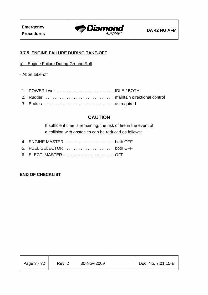
EmergencyProcedures
DA 42 NG AFM
Page 3 - 32 Rev. 2 30-Nov-2009 Doc. No. 7.01.15-E
3.7.5 ENGINE FAILURE DURING TAKE-OFF
a) Engine Failure During Ground Roll
- Abort take-off
1. POWER lever . . . . . . . . . . . . . . . . . . . . . . . . IDLE / BOTH2. Rudder . . . . . . . . . . . . . . . . . . . . . . . . . . . . . maintain directional control3. Brakes . . . . . . . . . . . . . . . . . . . . . . . . . . . . . . as required
CAUTIONIf sufficient time is remaining, the risk of fire in the event ofa collision with obstacles can be reduced as follows:
4. ENGINE MASTER . . . . . . . . . . . . . . . . . . . . both OFF5. FUEL SELECTOR . . . . . . . . . . . . . . . . . . . . . both OFF6. ELECT. MASTER . . . . . . . . . . . . . . . . . . . . . OFF
END OF CHECKLIST

DA 42 NG AFMEmergencyProcedures
Doc. No. 7.01.15-E Rev. 2 30-Nov-2009 Page 3 - 33
b) Engine Failure After Lift Off
If the landing gear is still extended and the remaining runway / surface is adequate:
- abort the take-off & land straight ahead
If the remaining runway / surface is inadequate:
- decide whether to abort or to continue the take-off
Continued take-off:
WARNINGA continued take-off is not recommended if the steady rateof climb according to Section 5.3.8 - ONE ENGINEINOPERATIVE CLIMB PERFORMANCE is less than 3.3 %.Under certain combinations of ambient conditions, such asturbulence, crosswinds and wind shear as well as pilot skillthe resulting climb performance may nevertheless beinsufficient to continue the take-off successfully. Thereforea continued take-off with a failed engine has to be avoidedif at all possible.
1. POWER lever . . . . . . . . . . . . . . . . . . . . . . . . MAX2. Rudder . . . . . . . . . . . . . . . . . . . . . . . . . . . . . maintain directional control3. Airspeed . . . . . . . . . . . . . . . . . . . . . . . . . . . . vYSE = 85 KIAS / as required4. Landing gear . . . . . . . . . . . . . . . . . . . . . . . . . UP to achieve a positive ROC5. FLAPS . . . . . . . . . . . . . . . . . . . . . . . . . . . . . check UP
CONTINUED

EmergencyProcedures
DA 42 NG AFM
Page 3 - 34 Rev. 2 30-Nov-2009 Doc. No. 7.01.15-E
6. Inoperative engine . . . . . . . . . . . . . . . . . . . . . secure according to 3.7.3 - ENGINE SECURING(FEATHERING) PROCEDURE
Land as soon as possible according to 3.7.7 - LANDING WITH ONE ENGINEINOPERATIVE. If a diversion is required before landing continue according to Section3.7.9 - FLIGHT WITH ONE ENGINE INOPERATIVE.
END OF CHECKLIST

DA 42 NG AFMEmergencyProcedures
Doc. No. 7.01.15-E Rev. 2 30-Nov-2009 Page 3 - 35
3.7.6 ENGINE FAILURES IN FLIGHT
(a) Engine Failure During Initial Climb
WARNINGAs the climb is a flight condition which is associated with highpower settings, airspeeds lower than vMCA = 76 KIAS shouldbe avoided as a sudden engine failure can lead to loss ofcontrol. In this case it is very important to reduce theasymmetry in thrust to regain directional control.
1. Rudder . . . . . . . . . . . . . . . . . . . . . . . . . . . . . maintain directional control
2. Airspeed . . . . . . . . . . . . . . . . . . . . . . . . . . . . vYSE = 85 KIAS/ above vMCA = 76 KIAS as required
3. Operative engine . . . . . . . . . . . . . . . . . . . . . increase power as required ifdirectional control has beenestablished
Establish minimum / zero sideslip condition. (approx. half ball towards good engine;3° to 5° bank)
4. Inoperative engine . . . . . . . . . . . . . . . . . . . . Secure according to 3.7.3 -ENGINE SECURING(FEATHERING) PROCEDURE
Land as soon as possible according to 3.7.7 - LANDING WITH ONE ENGINEINOPERATIVE. If a diversion is required before landing continue according to Section3.7.9 - FLIGHT WITH ONE ENGINE INOPERATIVE.
END OF CHECKLIST

EmergencyProcedures
DA 42 NG AFM
Page 3 - 36 Rev. 2 30-Nov-2009 Doc. No. 7.01.15-E
(b) Engine Failure During Flight
1. Rudder . . . . . . . . . . . . . . . . . . . . . . . . . . . . . maintain directional control
2. Airspeed . . . . . . . . . . . . . . . . . . . . . . . . . . . . as required /above vMCA = 76 KIAS
3. Operative engine . . . . . . . . . . . . . . . . . . . . . . increase power up to 92% loador maximum 2100 RPM
Establish minimum / zero sideslip condition. (approx. half ball towards good engine;3° to 5° bank)
4. Inoperative engine . . . . . . . . . . . . . . . . . . . . . Secure according to 3.7.3 -ENGINE SECURING(FEATHERING) PROCEDURE.
Land as soon as possible according to 3.7.7 - LANDING WITH ONE ENGINEINOPERATIVE. If a diversion is required before landing continue according to Section3.7.9 - FLIGHT WITH ONE ENGINE INOPERATIVE.
END OF CHECKLIST

DA 42 NG AFMEmergencyProcedures
Doc. No. 7.01.15-E Rev. 2 30-Nov-2009 Page 3 - 37
3.7.7 LANDING WITH ONE ENGINE INOPERATIVE
Preparation:
CAUTIONFor emergency landing the adjustable backrests (ifinstalled) must be fixed in the upright position.
1. Adjustable backrests (if installed) . . . . . . . . . adjust to the upright positiondescribed by a placard on the roll-over bar and verify proper fixation
2. Safety harnesses . . . . . . . . . . . . . . . . . . . . . check fastened & tightened3. Landing light . . . . . . . . . . . . . . . . . . . . . . . . . as required4. Gear warning horn . . . . . . . . . . . . . . . . . . . . check function
Operative engine:
5. Fuel pump remaining engine . . . . . . . . . . . . ON6. FUEL SELECTOR . . . . . . . . . . . . . . . . . . . . check ON
CAUTIONSwitching on the fuel pump in combination with CROSSFEEDmay cause damage to the high-pressure pump.
CAUTION If CROSSFEED is necessary with pumps ON, specialmaintenance is required before next flight.
CONTINUED

EmergencyProcedures
DA 42 NG AFM
Page 3 - 38 Rev. 2 30-Nov-2009 Doc. No. 7.01.15-E
Inoperative engine:
7. Engine . . . . . . . . . . . . . . . . . . . . . . . . . . . . . . check secured (feathered)according to 3.7.3 - ENGINESECURING & FEATHERINGPROCEDURE
not before being certain of "making the field“:
8. Airspeed . . . . . . . . . . . . . . . . . . . . . . . . . . . . as required to operate landinggear
9. Landing gear . . . . . . . . . . . . . . . . . . . . . . . . . DOWN, check 3 green10. Trim . . . . . . . . . . . . . . . . . . . . . . . . . . . . . . . . as required11. Airspeed . . . . . . . . . . . . . . . . . . . . . . . . . . . . reduce as required12. FLAPS . . . . . . . . . . . . . . . . . . . . . . . . . . . . . . as required
13. Final approach speed . . . . . . . . . . . . . . . . . . 86 KIAS (vREF/FLAPS UP)84 KIAS (vREF/FLAPS APP)84 KIAS (vREF/FLAPS LDG)
WARNINGOne-engine inoperative approaches for landing with flapsettings of more than flaps UP are not recommended unlessa safe landing is assured („Making the field“). Higher flapsettings increase the loss of altitude during the transition toa one engine inoperative go-around / balked landing.
14. POWER lever . . . . . . . . . . . . . . . . . . . . . . . . as required15. Trim . . . . . . . . . . . . . . . . . . . . . . . . . . . . . . . . as required / directional trim to
neutral
CONTINUED

DA 42 NG AFMEmergencyProcedures
Doc. No. 7.01.15-E Rev. 2 30-Nov-2009 Page 3 - 39
NOTEHigher approach speeds result in a significantly longer landingdistance during flare.
CAUTIONIn conditions such as (e.g.) strong wind, danger of wind shearor turbulence a higher approach speed should be selected.
- Perform normal touchdown and deceleration on ground.
END OF CHECKLIST

EmergencyProcedures
DA 42 NG AFM
Page 3 - 40 Rev. 2 30-Nov-2009 Doc. No. 7.01.15-E
If the approach to land is not successful you may consider:
3.7.8 GO-AROUND / BALKED LANDING WITH ONE ENGINE INOPERATIVE
CAUTIONThe go-around / balked landing is not recommended to beinitiated below a minimum of 800 ft above ground.
For performance data with one engine inoperative and flapsand gear UP refer to 5.3.8 - ONE ENGINE INOPERATIVECLIMB PERFORMANCE.
Under certain combinations of ambient conditions, such asturbulence, cross wind and windshear, as well as pilot skill,the resulting climb performance may nevertheless beinsufficient for a successful go-around / balked landing.
1. POWER lever . . . . . . . . . . . . . . . . . . . . . . . . MAX2. Rudder . . . . . . . . . . . . . . . . . . . . . . . . . . . . . maintain directional control3. Airspeed . . . . . . . . . . . . . . . . . . . . . . . . . . . . vYSE = 85 KIAS / as required4. Landing gear . . . . . . . . . . . . . . . . . . . . . . . . . UP / retract5. FLAPS . . . . . . . . . . . . . . . . . . . . . . . . . . . . . . UP
- Establish minimum sideslip and manoeuver for a new attempt to land. Repeat fromstep 1 of section 3.7.9 - FLIGHT WITH ONE ENGINE INOPERATIVE.
CONTINUED

DA 42 NG AFMEmergencyProcedures
Doc. No. 7.01.15-E Rev. 2 30-Nov-2009 Page 3 - 41
If a positive rate of climb cannot be established:
- Land so as to keep clear of obstacles. '
If time allows the following steps can reduce the risk of fire in an event of collisionwith obstacles after touchdown:
6. ENGINE MASTER . . . . . . . . . . . . . . . . . . . . both OFF7. FUEL SELECTOR . . . . . . . . . . . . . . . . . . . . both OFF8. FLAPS . . . . . . . . . . . . . . . . . . . . . . . . . . . . . APP or LDG, as required'
NOTE'
If landing is performed off airfield, it may be beneficial to land'
with the gear UP to avoid excessive damage to the airplane.'
Note that the energy absorbing function of the landing gear'
is lost in such cases.'
NOTE'
Extending the gear and extending the flaps to LDG will'
increase drag and incur a high sink rate. Only when the'
landing area can be reached safely, landing with flaps LDG'
is advisable. '
9. Approach speed . . . . . . . . . . . . . . . . . . . . . . min. 84 KIAS flaps APP'
min. 84 KIAS flaps LDG'
If landing with landing gear extended:'
10. LANDING GEAR . . . . . . . . . . . . . . . . . . . . . . DOWN, check 3 green'
11. ELECT. MASTER . . . . . . . . . . . . . . . . . . . . . OFF'
12. Touch down . . . . . . . . . . . . . . . . . . . . . . . . . lowest practical speed'
CONTINUED'

EmergencyProcedures
DA 42 NG AFM
Page 3 - 42 Rev. 2 30-Nov-2009 Doc. No. 7.01.15-E
If landing with landing gear retracted:'
10. LANDING GEAR . . . . . . . . . . . . . . . . . . . . . . UP'
11. Touch down . . . . . . . . . . . . . . . . . . . . . . . . . lowest practical speed'
'
Immediately after touch down:'
12. ELECT. MASTER . . . . . . . . . . . . . . . . . . . . . OFF'
END OF CHECKLIST

DA 42 NG AFMEmergencyProcedures
Doc. No. 7.01.15-E Rev. 2 30-Nov-2009 Page 3 - 43
3.7.9 FLIGHT WITH ONE ENGINE INOPERATIVE
CAUTIONEven if a positive flight performance can be established withone engine inoperative, land as soon as possible at the nextsuitable airfield / airport.
1. Airspeed . . . . . . . . . . . . . . . . . . . . . . . . . . . . above vMCA = 76 KIAS tomaintain directional control
2. Remaining engine . . . . . . . . . . . . . . . . . . . . . monitor engine instrumentscontinuously
3. Fuel quantity . . . . . . . . . . . . . . . . . . . . . . . . . monitor continuously4. Fuel pump LH/RH . . . . . . . . . . . . . . . . . . . . . check OFF
5. FUEL SELECTOR . . . . . . . . . . . . . . . . . . . . remaining engine / setCROSSFEED or ON so as tokeep fuel quantity laterallybalanced
CAUTIONSwitching the fuel pump to ON in combination withCROSSFEED may cause damage to the high-pressure pump.
CONTINUED

EmergencyProcedures
DA 42 NG AFM
Page 3 - 44 Rev. 2 30-Nov-2009 Doc. No. 7.01.15-E
NOTEIf the FUEL SELECTOR is set on CROSSFEED, the enginewill be supplied with fuel from the main tank on the oppositeside.
This will extend range and helps to keep the wings laterallybalanced (see 2.14 - FUEL).
Land as soon as possible according to Section 3.7.7 - LANDING WITH ONE ENGINEINOPERATIVE.
END OF CHECKLIST

DA 42 NG AFMEmergencyProcedures
Doc. No. 7.01.15-E Rev. 2 30-Nov-2009 Page 3 - 45
3.8 ENGINES OUT LANDING'
1. ENGINE MASTER . . . . . . . . . . . . . . . . . . . . both OFF'
2. Alternator switches . . . . . . . . . . . . . . . . . . . . both OFF'
3. Fuel pumps . . . . . . . . . . . . . . . . . . . . . . . . . . both OFF'
4. FUEL SELECTOR . . . . . . . . . . . . . . . . . . . . both OFF'
5. AVIONIC MASTER . . . . . . . . . . . . . . . . . . . . OFF'
6. Safety harnesses . . . . . . . . . . . . . . . . . . . . . check fastened and tightened'
'
When sure of making landing area:'
7. FLAPS . . . . . . . . . . . . . . . . . . . . . . . . . . . . . APP or LDG, as required'
NOTE'
If landing is performed off airfield, it may be beneficial to land'
with the gear UP to avoid excessive damage to the airplane.'
Note that the energy absorbing function of the landing gear'
is lost in such cases.'
NOTE'
Extending the gear and extending the flaps to LDG will'
increase drag and incur a high sink rate. Only when the'
landing area can be reached safely, landing with flaps LDG'
is advisable. '
8. Approach speed . . . . . . . . . . . . . . . . . . . . . . min. 84 KIAS flaps APP'
min. 84 KIAS flaps LDG'
If landing with landing gear extended:'
9. LANDING GEAR . . . . . . . . . . . . . . . . . . . . . . DOWN, check 3 green'
10. ELECT. MASTER . . . . . . . . . . . . . . . . . . . . . OFF'
11. Touch down . . . . . . . . . . . . . . . . . . . . . . . . . lowest practical speed'
CONTINUED'

EmergencyProcedures
DA 42 NG AFM
Page 3 - 46 Rev. 2 30-Nov-2009 Doc. No. 7.01.15-E
If landing with landing gear retracted:'
9. LANDING GEAR . . . . . . . . . . . . . . . . . . . . . . UP'
10. Touch down . . . . . . . . . . . . . . . . . . . . . . . . . lowest practical speed'
'
Immediately after touch down:'
11. ELECT. MASTER . . . . . . . . . . . . . . . . . . . . . OFF'
END OF CHECKLIST'

DA 42 NG AFMEmergencyProcedures
Doc. No. 7.01.15-E Rev. 2 30-Nov-2009 Page 3 - 47
3.9 LANDING GEAR SYSTEM FAILURES
3.9.1 LANDING GEAR UNSAFE WARNING
NOTEThe landing gear unsafe warning light illuminates if thelanding gear is neither in the final up or down & lockedposition. Illumination of this light is therefore normal duringtransit.
If the light remains on for longer than 20 seconds during landing gear retraction /extension:
1. Airspeed . . . . . . . . . . . . . . . . . . . . . . . . . . . . check below vLOR = 152 KIAS2. Gear selector . . . . . . . . . . . . . . . . . . . . . . . . re-cycle if continued illumination
occursIf the landing gear cannot be extended to the down & locked position or red light doesnot extinguish:
- Continue with 3.8.2 - MANUAL EXTENSION OF THE LANDING GEAR.
CONTINUED

EmergencyProcedures
DA 42 NG AFM
Page 3 - 48 Rev. 2 30-Nov-2009 Doc. No. 7.01.15-E
NOTEIf the landing gear cannot be retracted to the final up positionyou may continue the flight with the landing gear extendedin the down & locked position. Consider for higheraerodynamic drag, resulting in degraded flight performance,increased fuel consumption and decreased range.
With the landing gear extended and at aft CG-locations, withflaps up and full power applied, the airplane will easily recoverfrom sideslip if the trim is set to neutral (normal procedure).Otherwise it may require corrective action with a moderateamount of rudder input.
In cold ambient temperatures it may help to reduce theairspeed below 110 KIAS for landing gear operation.
END OF CHECKLIST

DA 42 NG AFMEmergencyProcedures
Doc. No. 7.01.15-E Rev. 2 30-Nov-2009 Page 3 - 49
3.9.2 MANUAL EXTENSION OF THE LANDING GEAR
NOTEIn case of a failure of the electrical pump, which is driving thelanding gear actuators, the landing gear can be extendedmanually at speeds up to 152 KIAS. The manual extensionof the landing gear may take up to 20 seconds.
The following checks shall be completed before extending the landing gear manually:
1. Gear indicator lights . . . . . . . . . . . . . . . . . . . test / push test button2. ELECT. MASTER . . . . . . . . . . . . . . . . . . . . check ON3. Bus voltage . . . . . . . . . . . . . . . . . . . . . . . . . . check in normal range4. Circuit breaker . . . . . . . . . . . . . . . . . . . . . . . check in / reset if necessary
Manual landing gear extension procedure:
5. Gear selector . . . . . . . . . . . . . . . . . . . . . . . . select DOWN6. Manual gear extension handle . . . . . . . . . . . pull out
NOTEThe landing gear should now extend by gravity and relief ofhydraulic pressure from the system. If one or more landinggear indicator lights do not indicate the gear down & lockedafter completion of the manual extension procedure steps1 - 6 reduce airspeed below 110 KIAS and apply moderateyawing and pitching to bring the landing gear into the lockedposition.
CONTINUED
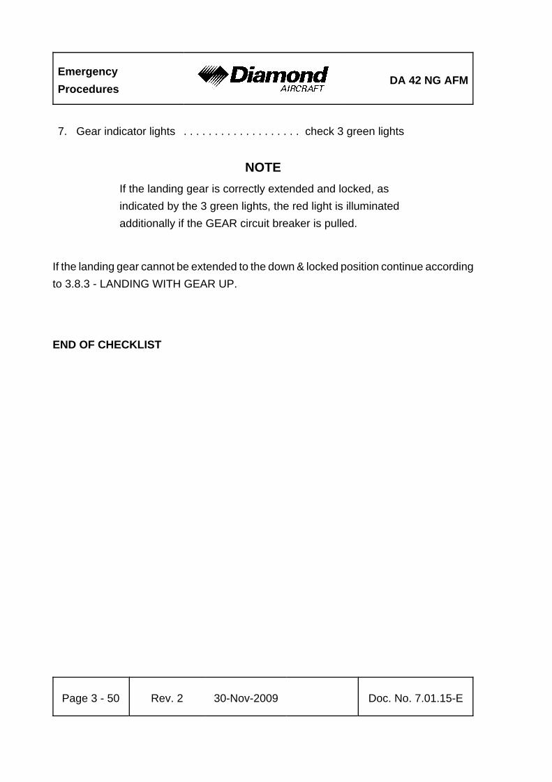
EmergencyProcedures
DA 42 NG AFM
Page 3 - 50 Rev. 2 30-Nov-2009 Doc. No. 7.01.15-E
7. Gear indicator lights . . . . . . . . . . . . . . . . . . . check 3 green lights
NOTEIf the landing gear is correctly extended and locked, asindicated by the 3 green lights, the red light is illuminatedadditionally if the GEAR circuit breaker is pulled.
If the landing gear cannot be extended to the down & locked position continue accordingto 3.8.3 - LANDING WITH GEAR UP.
END OF CHECKLIST

DA 42 NG AFMEmergencyProcedures
Doc. No. 7.01.15-E Rev. 2 30-Nov-2009 Page 3 - 51
3.9.3 LANDING WITH GEAR UP
NOTEThis procedure applies if the landing gear is completelyretracted.
1. Approach . . . . . . . . . . . . . . . . . . . . . . . . . . . with power at normal approachairspeeds and flap settings
2. POWER lever . . . . . . . . . . . . . . . . . . . . . . . IDLE / just beforetouchdown
If the time / situation allows, the following steps can help to reduce the risk of fire:
3. ENGINE MASTER . . . . . . . . . . . . . . . . . . . . both OFF4. Fuel pumps . . . . . . . . . . . . . . . . . . . . . . . . . . check OFF5. FUEL SELECTOR . . . . . . . . . . . . . . . . . . . . both OFF6. ELECT. MASTER . . . . . . . . . . . . . . . . . . . . . OFF
Touchdown:
7. Touchdown . . . . . . . . . . . . . . . . . . . . . . . . . contact surface with minimumairspeed
8. On ground . . . . . . . . . . . . . . . . . . . . . . . . . . maintain directional control withrudder as long as possible so asto avoid collision with obstacles
END OF CHECKLIST

EmergencyProcedures
DA 42 NG AFM
Page 3 - 52 Rev. 2 30-Nov-2009 Doc. No. 7.01.15-E
3.9.4 LANDING WITH A DEFECTIVE TIRE ON THE MAIN LANDING GEAR
CAUTIONA defective (e.g. burst) tire is not usually easy to detect. Thedamage normally occurs during take-off or landing, and ishardly noticeable during fast taxiing. It is only during the roll-out after landing or at lower taxiing speeds that a tendencyto swerve occurs. Rapid and determined action is thenrequired.
1. Land the airplane at the edge of the runway that is located on the side of the intacttire, so that changes in direction which must be expected during roll-out due to thebraking action of the defective tire can be corrected on the runway.
2. Land with one wing low. The wing on the side of the intact tire should be held low.
3. Direction should be maintained using the rudder. This should be supported by useof the brake. It is possible that the brake must be applied strongly - if necessaryto the point where the wheel locks. The wide track of the landing gear will preventthe airplane from tipping over a wide speed range. There is no pronounced tendencyto tip even when skidding.
END OF CHECKLIST

DA 42 NG AFMEmergencyProcedures
Doc. No. 7.01.15-E Rev. 2 30-Nov-2009 Page 3 - 53
3.9.5 LANDING WITH DEFECTIVE BRAKES
Consider the greater rolling distance.
Safety harness . . . . . . . . . . . . . . . . . . . . . . . . . . . check fastened and tightened
CAUTIONIf sufficient time is remaining, the risk of fire in the event ofa collision can be reduced as follows after a safe touch-down:
- ENGINE MASTER . . . . . . . . . . . both OFF
- FUEL SELECTOR . . . . . . . . . . . both OFF
- ELECT. MASTER . . . . . . . . . . . . OFF
END OF CHECKLIST

EmergencyProcedures
DA 42 NG AFM
Page 3 - 54 Rev. 2 30-Nov-2009 Doc. No. 7.01.15-E
3.10 FAILURES IN THE ELECTRICAL SYSTEM
3.10.1 COMPLETE FAILURE OF THE ELECTRICAL SYSTEM
1. Circuit breakers . . . . . . . . . . . . . . . . . . . . . . . check if all OK (pressed in)
if there is still no electrical power available:
2. EMERGENCY SWITCH . . . . . . . . . . . . . . . . ON3. Flood light, if necessary . . . . . . . . . . . . . . . . ON4. POWER . . . . . . . . . . . . . . . . . . . . . . . . . . . . set based on lever positions
and engine noise5. Prepare landing with flaps in the given position. Refer to 4B.5 - FAILURES IN
FLAP OPERATING SYSTEM.6. Land on the nearest suitable airfield.
WARNINGEngine stoppage may occur, depending on the failure mode.Backup batteries are installed for the ECUs to provideelectrical power solely to the ECU and their systems for atleast 30 minutes.
NOTEThe landing gear uplock is no longer ensured. The landinggear may slowly extend.
The landing gear can be extended manually according to3.9.2 - MANUAL EXTENSION OF THE LANDING GEAR.
NOTEThe backup artificial horizon and the flood light will haveelectrical power for at least 1.5 hours.
CONTINUED

DA 42 NG AFMEmergencyProcedures
Doc. No. 7.01.15-E Rev. 2 30-Nov-2009 Page 3 - 55
Make use of the stand-by airspeed indicator and altimeter. Engine power can be set viavisual reference of the POWER lever position.
END OF CHECKLIST
3.10.2 HIGH CURRENT
If high current is indicated on the G1000:
1. Circuit breakers . . . . . . . . . . . . . . . . . . . . . . check2. Reduce electric load to minimum required for continued safe flight.3. Land on the nearest suitable airfield.
END OF CHECKLIST
3.10.3 STARTER MALFUNCTION
If the starter does not disengage from the engine after starting (starter engagedwarning (STARTER L/R) on the G1000 annunciator field illuminates after the enginehas started):
On Ground:
1. POWER lever affected engine . . . . . . . . . . . IDLE2. ENGINE MASTER affected engine . . . . . . . . OFF3. ELECT. MASTER . . . . . . . . . . . . . . . . . . . . . OFF
Terminate flight preparation.
In flight:
Terminate flight.
END OF CHECKLIST

EmergencyProcedures
DA 42 NG AFM
Page 3 - 56 Rev. 2 30-Nov-2009 Doc. No. 7.01.15-E
3.11 SMOKE AND FIRE
NOTEThe cabin hand fire extinguisher is located inside theairplane passenger compartment on the RH side of thecabin floor behind the co-pilot seat.
To release the fire extinguisher bottle out of the bracket, itis necessary to catch the bottle at the agent-outlet nozzlenear the Y-spring.
3.11.1 ENGINE FIRE ON GROUND
1. ENGINE MASTER . . . . . . . . . . . . . . . . . . . . both OFF2. FUEL SELECTOR . . . . . . . . . . . . . . . . . . . . . both OFF3. ELECT. MASTER . . . . . . . . . . . . . . . . . . . . . OFF
after standstill:
4. Canopy . . . . . . . . . . . . . . . . . . . . . . . . . . . . . open5. Airplane . . . . . . . . . . . . . . . . . . . . . . . . . . . . . evacuate immediately
END OF CHECKLIST

DA 42 NG AFMEmergencyProcedures
Doc. No. 7.01.15-E Rev. 2 30-Nov-2009 Page 3 - 57
3.11.2 ENGINE FIRE DURING TAKE-OFF
1. Cabin heat & Defrost . . . . . . . . . . . . . . . . . . . OFF
CAUTIONIn case of extreme smoke development, the front canopy maybe unlatched during flight. This allows it to partially open, inorder to improve ventilation. The canopy will remain open inthis position. Flight characteristics will not be affectedsignificantly.
Proceed according to 3.7.5 - ENGINE FAILURES DURING TAKE-OFF.
END OF CHECKLIST

EmergencyProcedures
DA 42 NG AFM
Page 3 - 58 Rev. 2 30-Nov-2009 Doc. No. 7.01.15-E
3.11.3 ENGINE FIRE IN FLIGHT
1. Cabin heat & Defrost . . . . . . . . . . . . . . . . . . . OFF
CAUTIONIn case of extreme smoke development, the front canopy maybe unlatched during flight. This allows it to partially open, inorder to improve ventilation. The canopy will remain open inthis position. Flight characteristics will not be affectedsignificantly.
Proceed according to 3.7.6 - ENGINE FAILURES IN FLIGHT and shut down the engineaccording to 3.7.3 - ENGINE SECURING (FEATHERING) PROCEDURE.
END OF CHECKLIST

DA 42 NG AFMEmergencyProcedures
Doc. No. 7.01.15-E Rev. 2 30-Nov-2009 Page 3 - 59
3.11.4 ELECTRICAL FIRE ON GROUND
1. ELECT. MASTER . . . . . . . . . . . . . . . . . . . . . OFF
If the engine is running:
2. POWER lever . . . . . . . . . . . . . . . . . . . . . . . . both IDLE3. ENGINE MASTER . . . . . . . . . . . . . . . . . . . . both OFF4. FUEL SELECTOR . . . . . . . . . . . . . . . . . . . . both OFF
When the engine has stopped / after standstill:
5. Canopy . . . . . . . . . . . . . . . . . . . . . . . . . . . . . open6. Airplane . . . . . . . . . . . . . . . . . . . . . . . . . . . . evacuate immediately
END OF CHECKLIST

EmergencyProcedures
DA 42 NG AFM
Page 3 - 60 Rev. 2 30-Nov-2009 Doc. No. 7.01.15-E
3.11.5 ELECTRICAL FIRE IN FLIGHT
1. EMERGENCY SWITCH . . . . . . . . . . . . . . . . ON2. AVIONIC MASTER . . . . . . . . . . . . . . . . . . . . OFF3. ELECT. MASTER . . . . . . . . . . . . . . . . . . . . . OFF4. Cabin heat & Defrost . . . . . . . . . . . . . . . . . . . OFF5. Emergency windows . . . . . . . . . . . . . . . . . . . open if required6. Land at the next suitable airfield
CAUTIONSwitching OFF the ELECT. MASTER will lead to total failureof all electronic and electric equipment. The attitude andheading reference system (AHRS) will also be affected.
However, by switching the EMERGENCY switch ON, theemergency battery will supply power to the standby attitudegyro (artificial horizon) and the flood light.
In case of extreme smoke development, the front canopy maybe unlatched during flight. This allows it to be partially opened,in order to improve ventilation. The canopy will remain openin this position. Flight characteristics will not be affectedsignificantly.
The maximum demonstrated airspeed for emergency openingthe front canopy in flight is 117 KIAS. Do not exceed117 KIAS.
END OF CHECKLIST

DA 42 NG AFMEmergencyProcedures
Doc. No. 7.01.15-E Rev. 2 30-Nov-2009 Page 3 - 61
3.12 OTHER EMERGENCIES
3.12.1 SUSPICION OF CARBON MONOXIDE CONTAMINATION IN THE CABIN
Carbon monoxide (CO) is a gas which is developed during the combustion process. Itis poisonous and without smell. Increased concentration of carbon monoxide gas canbe fatal. The occurrence of CO in the cabin is possible only due to a defect. If a smellsimilar to exhaust gases is noticed in the cabin, the following measures should be taken:
1. Cabin heat & Defrost . . . . . . . . . . . . . . . . . . OFF2. Ventilation . . . . . . . . . . . . . . . . . . . . . . . . . . . open3. Emergency windows . . . . . . . . . . . . . . . . . . . open4. Forward canopy . . . . . . . . . . . . . . . . . . . . . . unlatch, push up and lock in
"cooling-gap“ position
CAUTIONThe maximum demonstrated airspeed for emergency openingthe front canopy in flight is 117 KIAS. Do not exceed117 KIAS.
END OF CHECKLIST

EmergencyProcedures
DA 42 NG AFM
Page 3 - 62 Rev. 2 30-Nov-2009 Doc. No. 7.01.15-E
3.12.2 UNLOCKED DOORS
1. Airspeed . . . . . . . . . . . . . . . . . . . . . . . . . . . . reduce immediately'
2. Canopy . . . . . . . . . . . . . . . . . . . . . . . . . . . . . check visually if closed3. Rear passenger door . . . . . . . . . . . . . . . . . . check visually if closed4. Front baggage doors . . . . . . . . . . . . . . . . . . . check visually if closed
Canopy Unlocked'
5. Airspeed . . . . . . . . . . . . . . . . . . . . . . . . . . . . below 140 KIAS'
6. Land at next suitable airfield.'
'
END OF CHECKLIST'
Rear Passenger Door Unlocked'
5. Airspeed . . . . . . . . . . . . . . . . . . . . . . . . . . . . below 140 KIAS'
6. Land at next suitable airfield.'
'
WARNING'
Do not try to lock the rear passenger door in flight. The safety'
latch may disengage and the door opens. Usually this results'
in a separation of the door from the airplane.'
Note'
If door has been lost the airplane can be safely flown to the'
next suitable airfield.'
'
END OF CHECKLIST'

DA 42 NG AFMEmergencyProcedures
Doc. No. 7.01.15-E Rev. 2 30-Nov-2009 Page 3 - 63
Front Baggage Door Open'
5. Airspeed . . . . . . . . . . . . . . . . . . . . . . . . . . . . reduce, so that door is in a '
stable position'
6. Land at next suitable airfield.'
'
WARNING'
Separation of the baggage door may damage the propeller'
and may lead to an engine failure.'
'
END OF CHECKLIST'

EmergencyProcedures
DA 42 NG AFM
Page 3 - 64 Rev. 2 30-Nov-2009 Doc. No. 7.01.15-E
3.12.3 DEFECTIVE PROPELLER RPM REGULATING SYSTEM
CAUTIONThe POWER lever should be moved slowly, in order to avoidover-speeding and excessively rapid RPM changes. The lightwooden propeller blades produce more rapid RPM changesthan metal blades.
WARNINGIn case of a malfunction of the engine control unit it is possiblethat the propeller blades will remain in the position of highestpitch. In this case the reduced engine performance shouldbe taken into consideration.
(a) Oscillating RPM
1. POWER setting . . . . . . . . . . . . . . . . . . . . . . . change
If the problem does not clear:
2. Garmin G1000 . . . . . . . . . . . . . . . . . . . . . . . check L/R ECU A/B FAIL caution
if L/R ECU A FAIL indicated:3. VOTER switch . . . . . . . . . . . . . . . . . . . . . . . . ECU B
if L/R ECU B FAIL indicated:3. VOTER switch . . . . . . . . . . . . . . . . . . . . . . . . ECU A
NOTEIf the problem does not clear itself, switch back to AUTO andland on the nearest suitable airfield.
CONTINUED

DA 42 NG AFMEmergencyProcedures
Doc. No. 7.01.15-E Rev. 2 30-Nov-2009 Page 3 - 65
(b) Propeller Overspeed
NOTEThis procedure applies for continued propeller overspeed dueto a malfunction in the propeller constant speed unit or aengine control unit malfunction.
1. POWER setting . . . . . . . . . . . . . . . . . . . . . . reduce as required
If the problem does not clear:
2. Garmin G1000 . . . . . . . . . . . . . . . . . . . . . . . check L/R ECU A/B FAIL caution
if L/R ECU A FAIL indicated:3. VOTER switch . . . . . . . . . . . . . . . . . . . . . . . ECU B
if L/R ECU B FAIL indicated:3. VOTER switch . . . . . . . . . . . . . . . . . . . . . . . ECU A
CAUTIONIf the problem does not clear itself, switch back to AUTO andland on the nearest suitable airfield. Prepare for enginemalfunction according to 3.7.6 - ENGINE FAILURES INFLIGHT.
CONTINUED

EmergencyProcedures
DA 42 NG AFM
Page 3 - 66 Rev. 2 30-Nov-2009 Doc. No. 7.01.15-E
(c) Fixed RPM
1. POWER setting . . . . . . . . . . . . . . . . . . . . . . . change
If the problem does not clear:
2. Garmin G1000 . . . . . . . . . . . . . . . . . . . . . . . check L/R ECU A/B FAIL caution
if L/R ECU A FAIL indicated:3. VOTER switch . . . . . . . . . . . . . . . . . . . . . . . . ECU B
if L/R ECU B FAIL indicated:3. VOTER switch . . . . . . . . . . . . . . . . . . . . . . . . ECU A
NOTEIf the problem does not clear itself, switch back to AUTO andland on the nearest suitable airfield.
END OF CHECKLIST

DA 42 NG AFMEmergencyProcedures
Doc. No. 7.01.15-E Rev. 2 30-Nov-2009 Page 3 - 67
3.12.4 UNINTENTIONAL FLIGHT INTO ICING
1. Leave the icing area (by changing altitude or turning back, in order to reachzones with a higher ambient temperature).
2. PITOT HEAT . . . . . . . . . . . . . . . . . . . . . . . . ON3. Cabin heat & Defrost . . . . . . . . . . . . . . . . . . ON4. POWER lever . . . . . . . . . . . . . . . . . . . . . . . . increase power, in order to
prevent ice build up on thepropeller blades, apply powerchanges periodically.
5. ALTERNATE AIR . . . . . . . . . . . . . . . . . . . . . OPEN6. Emergency windows . . . . . . . . . . . . . . . . . . . open if required
CAUTIONIce build-up increases the stalling speed.
7. ATC . . . . . . . . . . . . . . . . . . . . . . . . . . . . . . . advise if an emergency isexpected
END OF CHECKLIST

EmergencyProcedures
DA 42 NG AFM
Page 3 - 68 Rev. 2 30-Nov-2009 Doc. No. 7.01.15-E
3.12.5 FUEL SUPPLY FAILURE
1. FUEL SELECTOR . . . . . . . . . . . . . . . . . . . . CROSSFEED / affected engine
WARNINGIn case of a fuel supply failure a fuel pump inspection isrequired prior to the next flight.
2. Fuel quantity . . . . . . . . . . . . . . . . . . . . . . . . . monitor3. Fuel pump of affected engine . . . . . . . . . . . . ON
If fuel supply failure remains:
4. FUEL SELECTOR . . . . . . . . . . . . . . . . . . . . . ON5. Fuel pump of affected engine . . . . . . . . . . . . ON6. Fuel quantity . . . . . . . . . . . . . . . . . . . . . . . . . monitor
CAUTIONSwitching on the fuel pump in combination with CROSSFEEDmay cause damage to the high-pressure pump.
END OF CHECKLIST

DA 42 NG AFMEmergencyProcedures
Doc. No. 7.01.15-E Rev. 2 30-Nov-2009 Page 3 - 69
3.12.6 RECOVERY FROM AN UNINTENTIONAL SPIN
CAUTIONSpin recovery has NOT been shown during certification asit is NOT required for this airplane category. The givenrecovery method is based on general experience!
CAUTIONIntentional spins are prohibited in this airplane. In the eventa spin is encountered unintentionally, immediate recoveryactions must be taken.Single-engine stalling is not permitted.
CAUTIONSteps 1 to 4 must be carried out immediately andsimultaneously.
1. POWER lever . . . . . . . . . . . . . . . . . . . . . . . . IDLE2. Rudder . . . . . . . . . . . . . . . . . . . . . . . . . . . . . full deflection against
direction of spin3. Elevator (control stick) . . . . . . . . . . . . . . . . . fully forward4. Ailerons . . . . . . . . . . . . . . . . . . . . . . . . . . . . . neutral5. FLAPS . . . . . . . . . . . . . . . . . . . . . . . . . . . . . UP
CONTINUED

EmergencyProcedures
DA 42 NG AFM
Page 3 - 70 Rev. 2 30-Nov-2009 Doc. No. 7.01.15-E
When rotation has stopped:
6. Rudder . . . . . . . . . . . . . . . . . . . . . . . . . . . . . neutral7. Elevator (control stick) . . . . . . . . . . . . . . . . . . pull carefully8. Return the airplane from a descending into a normal flight attitude. Do not
exceed the 'never exceed speed', vNE = 188 KIAS.
END OF CHECKLIST

DA 42 NG AFMEmergencyProcedures
Doc. No. 7.01.15-E Rev. 2 30-Nov-2009 Page 3 - 71
3.12.7 EMERGENCY DESCENT
1. FLAPS . . . . . . . . . . . . . . . . . . . . . . . . . . . . . UP2. Gear . . . . . . . . . . . . . . . . . . . . . . . . . . . . . . . DOWN3. POWER lever . . . . . . . . . . . . . . . . . . . . . . . . IDLE4. Airspeed . . . . . . . . . . . . . . . . . . . . . . . . . . . . as required
WARNINGMax. structural cruising speed . . . . . . . vNO = 151 KIAS.
Never exceed speed in smooth air . . . . vNE = 188 KIAS.
END OF CHECKLIST
3.12.8 EMERGENCY EXIT
In case of a roll over of the airplane on ground, the rear side door can be used as exit.For this purpose unlock the front hinge of the rear side door. The function is displayedon a placard beside the hinge.
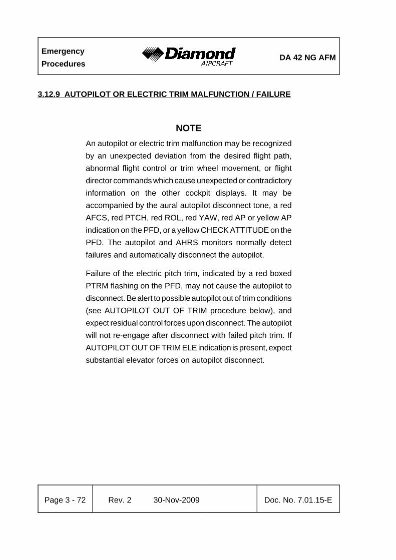
EmergencyProcedures
DA 42 NG AFM
Page 3 - 72 Rev. 2 30-Nov-2009 Doc. No. 7.01.15-E
3.12.9 AUTOPILOT OR ELECTRIC TRIM MALFUNCTION / FAILURE
NOTEAn autopilot or electric trim malfunction may be recognizedby an unexpected deviation from the desired flight path,abnormal flight control or trim wheel movement, or flightdirector commands which cause unexpected or contradictoryinformation on the other cockpit displays. It may beaccompanied by the aural autopilot disconnect tone, a redAFCS, red PTCH, red ROL, red YAW, red AP or yellow APindication on the PFD, or a yellow CHECK ATTITUDE on thePFD. The autopilot and AHRS monitors normally detectfailures and automatically disconnect the autopilot.
Failure of the electric pitch trim, indicated by a red boxedPTRM flashing on the PFD, may not cause the autopilot todisconnect. Be alert to possible autopilot out of trim conditions(see AUTOPILOT OUT OF TRIM procedure below), andexpect residual control forces upon disconnect. The autopilotwill not re-engage after disconnect with failed pitch trim. IfAUTOPILOT OUT OF TRIM ELE indication is present, expectsubstantial elevator forces on autopilot disconnect.

DA 42 NG AFMEmergencyProcedures
Doc. No. 7.01.15-E Rev. 2 30-Nov-2009 Page 3 - 73
NOTEAccomplish items 1 and 2 simultaneously!
1. Airplane control stick . . . . . . . . . . . . . . . . . . . grasp firmly and regain airplane control
2. AP DISC switch . . . . . . . . . . . . . . . . . . . . . . . DEPRESS AND HOLD3. Trim . . . . . . . . . . . . . . . . . . . . . . . . . . . . . . . . retrim airplane manually as
required4. AUTOPILOT circuit breaker . . . . . . . . . . . . . . pull5. AP DISC switch . . . . . . . . . . . . . . . . . . . . . . . RELEASE
NOTEWhen the AUTOPILOT circuit breaker is pulled, the manualelectric trim and autopilot autotrim systems will be disabled.
WARNINGDo not attempt to re-engage the autopilot following anautopilot, autotrim, or manual electric trim malfunctionuntil the cause for the malfunction has been corrected.
END OF CHECKLIST

EmergencyProcedures
DA 42 NG AFM
Page 3 - 74 Rev. 2 30-Nov-2009 Doc. No. 7.01.15-E
Intentionally left blank.

DA 42 NG AFMNormal Operating
Procedures
Doc. No. 7.01.15-E Rev. 2 30-Nov-2009 Page 4A - 1
CHAPTER 4ANORMAL OPERATING PROCEDURES
Page
4A.1 INTRODUCTION . . . . . . . . . . . . . . . . . . . . . . . . . . . . . . . . . . . . . 4A-34A.2 AIRSPEEDS FOR NORMAL OPERATING PROCEDURES . . . . 4A-44A.3 ADVISORY ALERTS ON THE G1000 . . . . . . . . . . . . . . . . . . . . . 4A-5
4A.3.1 ADVISORY/GENERAL . . . . . . . . . . . . . . . . . . . . . . . . . . . 4A-54A.3.2 L/R GLOW ON . . . . . . . . . . . . . . . . . . . . . . . . . . . . . . . . . 4A-54A.3.3 L/R AUXPUMP ON . . . . . . . . . . . . . . . . . . . . . . . . . . . . . . 4A-54A.3.4 PFD/MFD/GIA FAN FAIL . . . . . . . . . . . . . . . . . . . . . . . . . 4A-5
4A.4 FLIGHT CHARACTERISTICS . . . . . . . . . . . . . . . . . . . . . . . . . . . 4A-64A.5 DAILY CHECK . . . . . . . . . . . . . . . . . . . . . . . . . . . . . . . . . . . . . . . 4A-64A.6 CHECKLISTS FOR NORMAL OPERATING PROCEDURES . . . 4A-7
4A.6.1 PRE-FLIGHT INSPECTION . . . . . . . . . . . . . . . . . . . . . . . 4A-74A.6.2 BEFORE STARTING ENGINE . . . . . . . . . . . . . . . . . . . . 4A-194A.6.3 STARTING ENGINE . . . . . . . . . . . . . . . . . . . . . . . . . . . . 4A-224A.6.4 BEFORE TAXIING . . . . . . . . . . . . . . . . . . . . . . . . . . . . . 4A-244A.6.5 TAXIING . . . . . . . . . . . . . . . . . . . . . . . . . . . . . . . . . . . . . 4A-264A.6.6 BEFORE TAKE-OFF . . . . . . . . . . . . . . . . . . . . . . . . . . . 4A-274A.6.7 TAKE-OFF . . . . . . . . . . . . . . . . . . . . . . . . . . . . . . . . . . . 4A-334A.6.8 CLIMB . . . . . . . . . . . . . . . . . . . . . . . . . . . . . . . . . . . . . . 4A-344A.6.9 CRUISE . . . . . . . . . . . . . . . . . . . . . . . . . . . . . . . . . . . . . 4A-394A.6.10 DESCENT . . . . . . . . . . . . . . . . . . . . . . . . . . . . . . . . . . 4A-454A.6.11 APPROACH & LANDING . . . . . . . . . . . . . . . . . . . . . . . 4A-504A.6.12 GO AROUND . . . . . . . . . . . . . . . . . . . . . . . . . . . . . . . . 4A-56

Normal OperatingProcedures
DA 42 NG AFM
Page 4A - 2 Rev. 2 30-Nov-2009 Doc. No. 7.01.15-E
4A.6.13 AFTER LANDING . . . . . . . . . . . . . . . . . . . . . . . . . . . . . 4A-574A.6.14 SHUT-DOWN . . . . . . . . . . . . . . . . . . . . . . . . . . . . . . . . 4A-584A.6.15 EXIT AIRPLANE . . . . . . . . . . . . . . . . . . . . . . . . . . . . . . 4A-594A.6.16 POST FLIGHT INSPECTION . . . . . . . . . . . . . . . . . . . . 4A-594A.6.17 PARKING . . . . . . . . . . . . . . . . . . . . . . . . . . . . . . . . . . . 4A-594A.6.18 FLIGHT IN RAIN . . . . . . . . . . . . . . . . . . . . . . . . . . . . . . 4A-604A.6.19 REFUELING . . . . . . . . . . . . . . . . . . . . . . . . . . . . . . . . . 4A-604A.6.20 FLIGHT AT HIGH ALTITUDE . . . . . . . . . . . . . . . . . . . . 4A-604A.6.21 DEMONSTRATION OF ENGINE SHUTDOWN/RESTART%
. . . . . . . . . . . . . . . . . . . . . . . . . . . . . . . . . . . . . . . . . . . . . 4A-61

DA 42 NG AFMNormal Operating
Procedures
Doc. No. 7.01.15-E Rev. 2 30-Nov-2009 Page 4A - 3
4A.1 INTRODUCTION
Chapter 4A contains checklists and describes procedures for the normal operation of theairplane.
NOTEReadability of the G1000 PFD and MFD displays may bedegraded when wearing polarized sunglasses.
NOTENormal operating procedures for GFC 700 are described inthe Garmin G1000 Cockpit Reference Guide,P/N 190-00963-00 or later and the Garmin G1000 Pilot’sGuide for the Diamond DA 42 NG, P/N 190-00962-00 or later.

Normal OperatingProcedures
DA 42 NG AFM
Page 4A - 4 Rev. 2 30-Nov-2009 Doc. No. 7.01.15-E
4A.2 AIRSPEEDS FOR NORMAL OPERATING PROCEDURES
FLAPS Speed
Airspeed for rotation (take-off run, vR) UP min. 80 KIAS
Airspeed for take-off climb(best rate-of-climb speed vY)
UP min. 90 KIAS
Airspeed for best angle of climb UP 90 KIAS
Airspeed for cruise climb UP min. 90 KIAS
Reference landing approach speed UP 86 KIAS
APP min. 84 KIAS
Final approach speed LDG min. 84 KIAS
Minimum speed during go around UP min. 90 KIAS
Max. structural cruising speed
Do not exceed this speed except in smoothair, and then only with caution.
UP 151 KIAS

DA 42 NG AFMNormal Operating
Procedures
Doc. No. 7.01.15-E Rev. 2 30-Nov-2009 Page 4A - 5
4A.3 ADVISORY ALERTS ON THE G1000
The G1000 provides the following advisory-alerts on the PFD in the alert area:
4A.3.1 ADVISORY/GENERAL
CHARACTERISTICS White color coded text
4A.3.2 L/R GLOW ON
L/R GLOW ON Left / Right engine glow plug active
4A.3.3 L/R AUXPUMP ON
L/R AUXPUMP ON Fuel transfer from auxiliary to main tank is in progress (ifinstalled)
4A.3.4 PFD/MFD/GIA FAN FAIL
PFD FAN FAIL Cooling fan for the PFD is inoperative
MFD FAN FAIL Cooling fan for the MFD is inoperative
GIA FAN FAIL Cooling fan for the GIA is inoperative
The flight may be continued, but maintenance action is required after landing.

Normal OperatingProcedures
DA 42 NG AFM
Page 4A - 6 Rev. 2 30-Nov-2009 Doc. No. 7.01.15-E
4A.4 FLIGHT CHARACTERISTICS
The DA 42 NG is to be flown with "the feet on the pedals“, meaning that coordinated flightin all phases and configurations shall be supported by dedicated use of the rudder andailerons together.
With the landing gear extended and at aft CG-locations, with flaps up and full powerapplied, the airplane will easily recover from sideslip if the trim is set to neutral (normalprocedure), otherwise it may require corrective action with a moderate amount of rudderinput.
4A.5 DAILY CHECK
Before the first flight of a day it must be ensured that the following checks are performed.
* On-condition check of the canopy, the side door and the baggage compartment doorsfor cracks and major scratches.
* On-condition check of the hinges for the canopy, the side door and the baggagecompartment doors.
* Visual inspection of the locking bolts for proper movement with no backlash.
* Tire inflation pressure check (main wheels: 4.7 bar / 68 psi, nose wheel: 6.0 bar /87 psi).
* Visual inspection of both spinners and their attachment.

DA 42 NG AFMNormal Operating
Procedures
Doc. No. 7.01.15-E Rev. 2 30-Nov-2009 Page 4A - 7
4A.6 CHECKLISTS FOR NORMAL OPERATING PROCEDURES
4A.6.1 PRE-FLIGHT INSPECTION
I. Cabin check
Preparation:
a) Parking brake . . . . . . . . . . . . . . . . . . . . . . . . set ONb) MET, NAV, mass and balance . . . . . . . . . . . flight planning completedc) Airplane documents . . . . . . . . . . . . . . . . . . . complete and up to dated) Front canopy and rear door . . . . . . . . . . . . . clean, undamaged, check
locking mechanism functione) Baggage . . . . . . . . . . . . . . . . . . . . . . . . . . . . stowed and securedf) Foreign objects . . . . . . . . . . . . . . . . . . . . . . . check
Center console:
a) FUEL SELECTOR . . . . . . . . . . . . . . . . . . . . check ONb) POWER lever . . . . . . . . . . . . . . . . . . . . . . . . check condition, freedom of
movement and full travel/adjust friction, set IDLE
Below instrument panel in front of left seat:
a) ALTERNATE STATIC SOURCE . . . . . . . . . . check CLOSEDb) Manual gear extension handle . . . . . . . . . . . check pushed in
Below instrument panel in front of right seat:
a) ALTERNATE AIR . . . . . . . . . . . . . . . . . . . . . check CLOSED
CONTINUED

Normal OperatingProcedures
DA 42 NG AFM
Page 4A - 8 Rev. 2 30-Nov-2009 Doc. No. 7.01.15-E
On the instrument panel:
a) ALTERNATOR . . . . . . . . . . . . . . . . . . . . . . . check ONb) VOTER switch . . . . . . . . . . . . . . . . . . . . . . . . check AUTOc) PITOT HEAT . . . . . . . . . . . . . . . . . . . . . . . . . check OFFd) ENGINE MASTER . . . . . . . . . . . . . . . . . . . . check both OFFe) START KEY . . . . . . . . . . . . . . . . . . . . . . . . . check key is pulled outf) ELECT. MASTER . . . . . . . . . . . . . . . . . . . . . check OFFg) AVIONIC MASTER . . . . . . . . . . . . . . . . . . . . check OFFh) GEAR SELECTOR . . . . . . . . . . . . . . . . . . . . check DOWNi) FLAP SELECTOR . . . . . . . . . . . . . . . . . . . . . check UPj) Circuit breakers . . . . . . . . . . . . . . . . . . . . . . . set in (if one has been pulled,
check reason) k) All electrical equipment . . . . . . . . . . . . . . . . . OFF l) EMERGENCY switch . . . . . . . . . . . . . . . . . . check OFF and guardedm) ELT . . . . . . . . . . . . . . . . . . . . . . . . . . . . . . . . armed
Check procedure:a) ELECT. MASTER . . . . . . . . . . . . . . . . . . . . . ON
CAUTIONWhen switching the ELECT. MASTER ON, the electricallydriven hydraulic gear pump may activate itself for 5 to 20seconds in order to restore the system pressure. Should thepump continue to operate continuously or periodically,terminate flight. There is a malfunction in the landing gearsystem.
CONTINUED

DA 42 NG AFMNormal Operating
Procedures
Doc. No. 7.01.15-E Rev. 2 30-Nov-2009 Page 4A - 9
b) Fuel quantity . . . . . . . . . . . . . . . . . . . . . . . . . check indication, verify usingalternate means (see Section7.9.5)
c) Position lights, strobe lights (ACL) . . . . . . . . check for correct function
CAUTIONDo not look directly into the anti collision lights.
d) Landing / taxi light . . . . . . . . . . . . . . . . . . . . . check for correct functione) Stall warning / stall heat / Pitot heat . . . . . . . check
NOTEBecause the stall warning switch gets slightly warmer onground, STAL HT FAIL may be indicated on the PFD.
f) Gear warning / fire detector TEST BUTTON . . . . . . . . . . . . . PUSH, check aural alert/fire
detection warning and aural alertand CHECK GEAR caution
CAUTIONIf the aural alert or the warning on the PFD does not appear,terminate flight. Unscheduled maintenance is necessary.
g) Control stick . . . . . . . . . . . . . . . . . . . . . . . . . pull fully aft/hold at backstop
CONTINUED

Normal OperatingProcedures
DA 42 NG AFM
Page 4A - 10 Rev. 2 30-Nov-2009 Doc. No. 7.01.15-E
%
h) POWER lever . . . . . . . . . . . . . . . . . . . . . . . . set MAXi) Variable elevator backstop . . . . . . . . . . . . . . check function/control stick must
move slightly forward duringpower lever forward movement
j) POWER lever . . . . . . . . . . . . . . . . . . . . . . . . set IDLE k) Variable elevator backstop . . . . . . . . . . . . . . check function/control stick must
regain full movement duringpower lever retraction
%
CAUTIONThe proper function of the variable elevator backstop isindispensable for the safety of flight, as the handling qualitiesduring power-on stalls are degraded significantly. For moredetails see Chapter 7 - AIRPLANE DESCRIPTION ANDSYSTEMS.
If the variable elevator backstop does not function properly,terminate flight preparation.
l) ELECT. MASTER . . . . . . . . . . . . . . . . . . . . . OFF m) Flight controls . . . . . . . . . . . . . . . . . . . . . . . . check free and correct movement
up to full deflectionn) Trims . . . . . . . . . . . . . . . . . . . . . . . . . . . . . . . check free and correct movement
up to full deflection
END OF CHECKLIST

DA 42 NG AFMNormal Operating
Procedures
Doc. No. 7.01.15-E Rev. 2 30-Nov-2009 Page 4A - 11
II. Walk-around check, visual inspection
CAUTIONA visual inspection means: examination for damage, cracks,delamination, excessive play, load transmission, correctattachment and general condition. In addition control surfacesshould be checked for freedom of movement.
CAUTIONIn low ambient temperatures the airplane must be completelycleared of ice, snow and similar accumulations. For approvedde-icing fluids refer to Section 8.7 - GROUND DE-ICING.
CAUTIONPrior to flight, remove such items as control surfaces gustlock, Pitot cover, tow bar, etc.
1. Left main landing gear:
a) Landing gear strut and lock . . . . . . . . . . . . . visual inspection, sufficient height (typical visible length of barepiston: at least 4 cm/1.6 in)
b) Down and uplock switches (2x) . . . . . . . . . . visual inspectionc) Wear, tread depth of tire . . . . . . . . . . . . . . . . visual inspectiond) Tire, wheel, brake . . . . . . . . . . . . . . . . . . . . . visual inspectione) Brake line connection . . . . . . . . . . . . . . . . . . check for leaksf) Slip marks . . . . . . . . . . . . . . . . . . . . . . . . . . . visual inspectiong) Chocks . . . . . . . . . . . . . . . . . . . . . . . . . . . . . removeh) Landing gear door . . . . . . . . . . . . . . . . . . . . . visual inspection
CONTINUED

Normal OperatingProcedures
DA 42 NG AFM
Page 4A - 12 Rev. 2 30-Nov-2009 Doc. No. 7.01.15-E
2. Left engine nacelle:
a) 3 air inlets / 2 air outlets . . . . . . . . . . . . . . . . clearb) Engine oil level . . . . . . . . . . . . . . . . . . . . . . . check dipstick (inspection hole in
the upper cowling)c) Gearbox oil level . . . . . . . . . . . . . . . . . . . . . . check visually (inspection hole in
the upper cowling) %
d) Cowling . . . . . . . . . . . . . . . . . . . . . . . . . . . . . visual inspectione) Gascolator / air inlet . . . . . . . . . . . . . . . . . . . drain off to check for water and
sediment (drain until no watercomes out)/clear
f) Venting pipe . . . . . . . . . . . . . . . . . . . . . . . . . check for blockageg) Exhaust . . . . . . . . . . . . . . . . . . . . . . . . . . . . . visual inspection
WARNINGThe exhaust can cause burns when hot.
h) Propeller . . . . . . . . . . . . . . . . . . . . . . . . . . . . visual inspection
WARNINGNever move the propeller by hand while the ENGINEMASTER switch is ON! Also do not move the propeller byhand while the ENGINE MASTER is OFF immediately afteroperation (remaining pressure in the injection system rail).Serious personal injury may result.
i) De-icing boots (if OÄM 42-053 carried out) . . check for de-bonding
CONTINUED

DA 42 NG AFMNormal Operating
Procedures
Doc. No. 7.01.15-E Rev. 2 30-Nov-2009 Page 4A - 13
j) Nacelle underside . . . . . . . . . . . . . . . . . . . . . check for excessivecontamination particularly by oil,fuel, and other fluids
k) Auxiliary tank vent outlet on lower surface(if installed) . . . . . . . . . . . . . . . . . . . . . . . . . . visual inspection
l) Auxiliary tank drain (if installed) . . . . . . . . . . drain off to check for water and sediment (drain until no watercomes out) / visual inspection
m) Auxiliary tank filler (if installed) . . . . . . . . . . . visual inspection, tank filler closed
3. Left wing:
a) Entire wing surface . . . . . . . . . . . . . . . . . . . . visual inspectionb) Vortex generators . . . . . . . . . . . . . . . . . . . . . undamaged, 4 pieces, cleanc) Tank air outlet on lower surface . . . . . . . . . . visual inspectiond) Tank drain/tank air inlet . . . . . . . . . . . . . . . . drain off to check for water and
sediment (drain until no watercomes out)/visual inspection
e) Openings on lower surface . . . . . . . . . . . . . . check for foreign objects and fortraces of fuel (if tank is full, fuelmay spill over through the tankvent)
f) Stall warn device . . . . . . . . . . . . . . . . . . . . . . visual inspectiong) Tank filler . . . . . . . . . . . . . . . . . . . . . . . . . . . visual inspection, check closedh) Pitot probe . . . . . . . . . . . . . . . . . . . . . . . . . . clean, orifices clear, cover
removed, no deformationi) Wing tip . . . . . . . . . . . . . . . . . . . . . . . . . . . . . visual inspectionj) Static dischargers . . . . . . . . . . . . . . . . . . . . . visual inspectionk) Position light, strobe light (ACL) . . . . . . . . . . visual inspectionl) Tie-down . . . . . . . . . . . . . . . . . . . . . . . . . . . . check, clear
CONTINUED

Normal OperatingProcedures
DA 42 NG AFM
Page 4A - 14 Rev. 2 30-Nov-2009 Doc. No. 7.01.15-E
m) Aileron and linkage . . . . . . . . . . . . . . . . . . . . visual inspectionn) Aileron hinges and safety pin . . . . . . . . . . . . visual inspectiono) Foreign objects in aileron paddle . . . . . . . . . visual inspectionp) Flap and linkage . . . . . . . . . . . . . . . . . . . . . . visual inspectionq) Flap hinges and safety pin . . . . . . . . . . . . . . visual inspectionr) Nacelle underside fuel cooler air in- & outlet . check clears) Step . . . . . . . . . . . . . . . . . . . . . . . . . . . . . . . . visual inspection
4. Fuselage, left side, underside:
a) Canopy, left side . . . . . . . . . . . . . . . . . . . . . . visual inspectionb) Rear cabin door & window . . . . . . . . . . . . . . visual inspectionc) Fuselage skin . . . . . . . . . . . . . . . . . . . . . . . . visual inspectiond) Antennas . . . . . . . . . . . . . . . . . . . . . . . . . . . . visual inspectione) Fuselage . . . . . . . . . . . . . . . . . . . . . . . . . . . . check for contamination
(hydraulic fluid)f) Static source . . . . . . . . . . . . . . . . . . . . . . . . . check for blockage
5. Empennage:
a) Stabilizers and control surfaces,elevator tips . . . . . . . . . . . . . . . . . . . . . . . . . . visual inspection
b) Hinges . . . . . . . . . . . . . . . . . . . . . . . . . . . . . . visual inspectionc) Elevator trim tab . . . . . . . . . . . . . . . . . . . . . . visual inspection, check safetyingd) Rudder trim tab . . . . . . . . . . . . . . . . . . . . . . . visual inspection, check safetyinge) Tie-down . . . . . . . . . . . . . . . . . . . . . . . . . . . . check, clearf) Tail skid and lower fin . . . . . . . . . . . . . . . . . . visual inspectiong) Static dischargers . . . . . . . . . . . . . . . . . . . . . visual inspection
CONTINUED

DA 42 NG AFMNormal Operating
Procedures
Doc. No. 7.01.15-E Rev. 2 30-Nov-2009 Page 4A - 15
6. Fuselage, right side:
a) Fuselage skin . . . . . . . . . . . . . . . . . . . . . . . . visual inspectionb) Rear window . . . . . . . . . . . . . . . . . . . . . . . . . visual inspectionc) Canopy, right side . . . . . . . . . . . . . . . . . . . . . visual inspectiond) Static source . . . . . . . . . . . . . . . . . . . . . . . . . check for blockage
7. Right Main Landing Gear:
a) Landing gear strut and lock . . . . . . . . . . . . . visual inspection, sufficient height (typical visible length of barepiston: at least 4 cm/1.6")
b) Down and uplock switches (2x) . . . . . . . . . . visual inspectionc) Wear, tread depth of tire . . . . . . . . . . . . . . . . visual inspectiond) Tire, wheel, brake . . . . . . . . . . . . . . . . . . . . . visual inspectione) Brake line connection . . . . . . . . . . . . . . . . . . check for leaksf) Slip marks . . . . . . . . . . . . . . . . . . . . . . . . . . . visual inspectiong) Chocks . . . . . . . . . . . . . . . . . . . . . . . . . . . . . removeh) Landing gear door . . . . . . . . . . . . . . . . . . . . . visual inspection
8. Right wing:
a) Entire wing surface . . . . . . . . . . . . . . . . . . . . visual inspectionb) Vortex generators . . . . . . . . . . . . . . . . . . . . . undamaged, 4 pieces, cleanc) Tank air outlet on lower surface . . . . . . . . . . visual inspectiond) Tank drain/tank air inlet . . . . . . . . . . . . . . . . drain off to check for water and
sediment (drain until no watercomes out)/visual inspection
CONTINUED

Normal OperatingProcedures
DA 42 NG AFM
Page 4A - 16 Rev. 2 30-Nov-2009 Doc. No. 7.01.15-E
e) Openings on lower surface . . . . . . . . . . . . . . check for foreign objects and fortraces of fuel (if tank is full, fuelmay spill over through the tankvent)
f) Tank filler . . . . . . . . . . . . . . . . . . . . . . . . . . . visual inspection, check closedg) Wing tip . . . . . . . . . . . . . . . . . . . . . . . . . . . . . visual inspectionh) Static dischargers . . . . . . . . . . . . . . . . . . . . . visual inspectioni) Position light, strobe light (ACL) . . . . . . . . . . visual inspectionj) Tie-down . . . . . . . . . . . . . . . . . . . . . . . . . . . . check, cleark) Aileron and linkage . . . . . . . . . . . . . . . . . . . . visual inspectionl) Aileron hinges and safety pin . . . . . . . . . . . . visual inspectionm) Foreign objects in aileron paddle . . . . . . . . . visual inspectionn) Flap and linkage . . . . . . . . . . . . . . . . . . . . . . visual inspectiono) Flap hinges and safety pin . . . . . . . . . . . . . . visual inspectionp) Nacelle underside fuel cooler air in- & outlet . check clearq) Step . . . . . . . . . . . . . . . . . . . . . . . . . . . . . . . . visual inspectionr) Cabin vent air inlet . . . . . . . . . . . . . . . . . . . . check clear
9. Right engine nacelle:
a) 3 air inlets / 2 air outlets . . . . . . . . . . . . . . . . clearb) Engine oil level . . . . . . . . . . . . . . . . . . . . . . . check dipstick (inspection hole in
the upper cowling)c) Gearbox oil level . . . . . . . . . . . . . . . . . . . . . . check visually (inspection hole in
the upper cowling)%
d) Cowling . . . . . . . . . . . . . . . . . . . . . . . . . . . . . visual inspectione) Gascolator / air inlet . . . . . . . . . . . . . . . . . . . drain off to check for water and
sediment (drain until no watercomes out)/clear
CONTINUED

DA 42 NG AFMNormal Operating
Procedures
Doc. No. 7.01.15-E Rev. 2 30-Nov-2009 Page 4A - 17
f) Venting pipe . . . . . . . . . . . . . . . . . . . . . . . . . check for blockageg) Exhaust . . . . . . . . . . . . . . . . . . . . . . . . . . . . . visual inspection
WARNINGThe exhaust can cause burns when hot.
h) Propeller . . . . . . . . . . . . . . . . . . . . . . . . . . . . visual inspection
WARNINGNever move the propeller by hand while the ENGINEMASTER switch is ON! Also do not move the propeller byhand while the ENGINE MASTER is OFF immediately afteroperation (remaining pressure in the injection system rail).Serious personal injury may result.
i) De-icing boots (if OÄM 42-053 carried out) . check for de-bonding j) Nacelle underside . . . . . . . . . . . . . . . . . . . . . check for excessive
contamination particularly by oil,fuel, and other fluids
k) Auxiliary tank vent outlet on lower surface(if installed) . . . . . . . . . . . . . . . . . . . . . . . . . . visual inspection
l) Auxiliary tank drain (if installed) . . . . . . . . . . drain off to check for water andsediment (drain until no watercomes out)/visual inspection
m) Auxiliary tank filler (if installed) . . . . . . . . . . . visual inspection, tank filler closed
CONTINUED

Normal OperatingProcedures
DA 42 NG AFM
Page 4A - 18 Rev. 2 30-Nov-2009 Doc. No. 7.01.15-E
10. Front fuselage and nose landing gear:
a) Left and right front baggage door . . . . . . . . . visual inspection, closed andlocked
b) Nose landing gear strut . . . . . . . . . . . . . . . . . visual inspection, sufficient height (typical visible length of barepiston: at least 15 cm/5.9 in)
c) Down & uplock switches . . . . . . . . . . . . . . . . visual inspectiond) Wear, tread depth of tire . . . . . . . . . . . . . . . . checke) Slip marks . . . . . . . . . . . . . . . . . . . . . . . . . . . visual inspectionf) Gear door and linkage . . . . . . . . . . . . . . . . . . visual inspectiong) Chocks . . . . . . . . . . . . . . . . . . . . . . . . . . . . . removeh) OAT sensor . . . . . . . . . . . . . . . . . . . . . . . . . . checki) EPU connector . . . . . . . . . . . . . . . . . . . . . . . checkj) Tow bar . . . . . . . . . . . . . . . . . . . . . . . . . . . . . remove
END OF CHECKLIST

DA 42 NG AFMNormal Operating
Procedures
Doc. No. 7.01.15-E Rev. 2 30-Nov-2009 Page 4A - 19
4A.6.2 BEFORE STARTING ENGINE
1. Preflight inspection . . . . . . . . . . . . . . . . . . . . complete2. Passengers . . . . . . . . . . . . . . . . . . . . . . . . . instructed
NOTEEnsure all the passengers have been fully briefed on the useof the seat belts, doors and emergency exits and the ban onsmoking.
3. Rear door . . . . . . . . . . . . . . . . . . . . . . . . . . . closed and locked
CAUTIONWhen operating the canopy, pilots/operators must ensure thatthere are no obstructions between the canopy and the matingframe, for example seat belts, clothing, etc. When operatingthe locking handle do NOT apply undue force.
A slight downward pressure on the canopy may be requiredto ease the handle operation.
4. Front canopy . . . . . . . . . . . . . . . . . . . . . . . . . Position 1 or 2 (“cooling gap”)
CAUTIONFor take-off the adjustable backrests (if installed) must befixed in the upright position.
CONTINUED

Normal OperatingProcedures
DA 42 NG AFM
Page 4A - 20 Rev. 2 30-Nov-2009 Doc. No. 7.01.15-E
NOTEThe pilot must ensure that a passenger sitting on a front seatis instructed in the operation of the adjustable backrest (ifinstalled).
5. Adjustable backrests (if installed) . . . . . . . . . adjust to the upright position described by a placardon the roll-over bar and verifyproper fixation
6. Rudder pedals . . . . . . . . . . . . . . . . . . . . . . . . adjusted; if manual pedal adjustment isinstalled: verify proper locking
7. Safety harnesses . . . . . . . . . . . . . . . . . . . . . all on and fastened8. POWER lever . . . . . . . . . . . . . . . . . . . . . . . . check IDLE9. Parking brake . . . . . . . . . . . . . . . . . . . . . . . . set10. AVIONIC MASTER . . . . . . . . . . . . . . . . . . . check OFF11. GEAR selector . . . . . . . . . . . . . . . . . . . . . . . check DOWN12. VOTER switch . . . . . . . . . . . . . . . . . . . . . . . . check AUTO13. ALTERNATORS . . . . . . . . . . . . . . . . . . . . . . check ON14. Fuel pump LH/RH . . . . . . . . . . . . . . . . . . . . . check OFF15. ELECT. MASTER . . . . . . . . . . . . . . . . . . . . . ON
CAUTIONWhen switching the ELECT. MASTER ON, the electricallydriven hydraulic gear pump may activate itself for 5 to 20seconds in order to restore the system pressure. Should thepump continue to operate continuously or periodically,terminate flight preparation. There is a malfunction in thelanding gear system.
CONTINUED
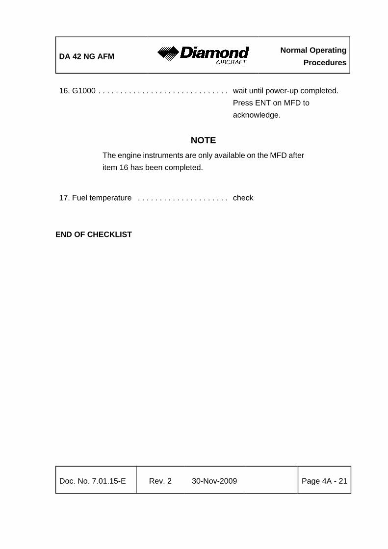
DA 42 NG AFMNormal Operating
Procedures
Doc. No. 7.01.15-E Rev. 2 30-Nov-2009 Page 4A - 21
16. G1000 . . . . . . . . . . . . . . . . . . . . . . . . . . . . . . wait until power-up completed. Press ENT on MFD toacknowledge.
NOTEThe engine instruments are only available on the MFD afteritem 16 has been completed.
17. Fuel temperature . . . . . . . . . . . . . . . . . . . . . check
END OF CHECKLIST

Normal OperatingProcedures
DA 42 NG AFM
Page 4A - 22 Rev. 2 30-Nov-2009 Doc. No. 7.01.15-E
4A.6.3 STARTING ENGINE
NOTEAt ambient temperatures below -22°C the engine may notstart at the first attempt. In this case wait 60 seconds betweenthe start attempts.
1. Strobe lights (ACL) . . . . . . . . . . . . . . . . . . . . ON2. ENGINE MASTER . . . . . . . . . . . . . . . . . . . . ON (L)3. Annunciations . . . . . . . . . . . . . . . . . . . . . . . . check "L ENGINE GLOW" ON
NOTE"L ENGINE GLOW" is indicated only when the engine is cold.
4. Annunciations / Engine / System Page . . . . . check OK/normal range
WARNINGBefore starting the engine the pilot must ensure that thepropeller area is free, and no persons can be endangered.
After the L ENGINE GLOW indication is extinguished:
5. START KEY . . . . . . . . . . . . . . . . . . . . . . . . . START L as required / releasewhen engine has started.
CONTINUED

DA 42 NG AFMNormal Operating
Procedures
Doc. No. 7.01.15-E Rev. 2 30-Nov-2009 Page 4A - 23
CAUTIONDo not overheat the starter motor. Do not operate the startermotor for more than 10 seconds.
At ambient temperatures below -22°C it is possible that theengine will not start at the first attempt. In this case wait60 seconds between the start attempts.
If the "L STARTER" annunciation comes on after the enginehas started and the START KEY has been released, set theENGINE MASTER to OFF and investigate the problem.
6. Annunciations / Engine / System Page . . . . . check OK/normal range7. Annunciations / Starter . . . . . . . . . . . . . . . . . check OFF8. Annunciations / Oil pressure . . . . . . . . . . . . . check OK
WARNINGIf the oil pressure has not moved from the red range within3 seconds after starting, set the ENGINE MASTER switchto OFF and investigate problem.
9. Circuit breakers . . . . . . . . . . . . . . . . . . . . . . check all in/as required10. Idle RPM . . . . . . . . . . . . . . . . . . . . . . . . . . . . check, 740 ±30 RPM
Repeat with opposite engine.
11. Warm up . . . . . . . . . . . . . . . . . . . . . . . . . . . . IDLE for 30 seconds, then at 50% load until: oil temperature 50°C (122°F) andcoolant temperature 60 °C (140°F)
END OF CHECKLIST

Normal OperatingProcedures
DA 42 NG AFM
Page 4A - 24 Rev. 2 30-Nov-2009 Doc. No. 7.01.15-E
4A.6.4 BEFORE TAXIING
1. AVIONIC MASTER . . . . . . . . . . . . . . . . . . . . ON 2. Electrical equipment . . . . . . . . . . . . . . . . . . . ON as required3. Flight instruments and avionics . . . . . . . . . . . set as required4. Flood light . . . . . . . . . . . . . . . . . . . . . . . . . . . ON, test function, as
required5. Pitot and stall warn heating . . . . . . . . . . . . . . ON, check annunciation
NOTEThe stall warning switch gets slightly warmer on ground onlyand STAL HT FAIL is indicated on the PFD.
6. Pitot and stall warn heating . . . . . . . . . . . . . . OFF 7. Strobe lights (ACL's) . . . . . . . . . . . . . . . . . . . check ON8. Position lights, landing and taxi lights . . . . . . as required
CAUTIONWhen taxiing at close range to other airplane, or during nightflight in clouds, fog or haze, the strobe lights should beswitched OFF. The position lights must always be switchedON during night flight.
9. Primary flight display (PFD) . . . . . . . . . . . . . NO AUTOPILOT ANNUNCIATIONS
10. Autopilot disconnect tone . . . . . . . . . . . . . . . NOTE
CONTINUED

DA 42 NG AFMNormal Operating
Procedures
Doc. No. 7.01.15-E Rev. 2 30-Nov-2009 Page 4A - 25
NOTEThe AFCS system automatically conducts a preflight self-testupon initial power application. The preflight test is indicatedby a white boxed PFT on the PFD. Upon successfulcompletion of the preflight test, the PFT is removed, the redAFCS annunciation is removed, and the autopilot disconnecttone sounds. If AFCS annunciation remains on or a failureof the preflight test is indicated terminate flight preparationand investigate the problem.
11. MANUAL ELECTRIC TRIM - TEST as follows: Press the AP DISC button down and hold while commanding trim. Manual electric trim should not operate either nose up or nose down.
12. AUTOPILOT . . . . . . . . . . . . . . . . . . . . . . . . . engage by pressing AP button13. AP DISC switch . . . . . . . . . . . . . . . . . . . . . . press. verify that the autopilot
disconnects14. TRIM . . . . . . . . . . . . . . . . . . . . . . . . . . . . . . . set to take-off position manually
END OF CHECKLIST

Normal OperatingProcedures
DA 42 NG AFM
Page 4A - 26 Rev. 2 30-Nov-2009 Doc. No. 7.01.15-E
4A.6.5 TAXIING
1. Parking brake . . . . . . . . . . . . . . . . . . . . . . . . release2. Brakes . . . . . . . . . . . . . . . . . . . . . . . . . . . . . . test on moving off3. Nose wheel steering . . . . . . . . . . . . . . . . . . . check for proper function4. Flight instrumentation and avionics . . . . . . . . check for correct indications5. Fuel pumps LH/RH . . . . . . . . . . . . . . . . . . . . check OFF6. FUEL SELECTOR . . . . . . . . . . . . . . . . . . . . . CROSSFEED (LH/RH)
CAUTIONThe fuel crossfeed function can be tested simultaneously withboth engines. Proper function can be tested by running theengines for approx. 30 seconds with CROSSFEED selected.The operation of both engines with both FUEL SELECTORSin CROSSFEED position, other than for this test, isprohibited.
CAUTIONSwitching on the fuel pump in combination with CROSSFEEDmay cause damage to the high-pressure pump.
7. FUEL SELECTOR . . . . . . . . . . . . . . . . . . . . ON (LH/RH)
CAUTIONWhen taxiing on a poor surface select the lowest possibleRPM to avoid damage to the propeller from stones or similaritems.
END OF CHECKLIST
DA 42 NG AFMNormal Operating
Procedures
Doc. No. 7.01.15-E Rev. 2 30-Nov-2009 Page 4A - 27
4A.6.6 BEFORE TAKE-OFF
1. Position airplane into wind if possible.2. Parking brake . . . . . . . . . . . . . . . . . . . . . . . . set
CAUTIONFor take-off the adjustable backrests (if installed) must befixed in the upright position.
3. Adjustable backrests (if installed) . . . . . . . . verify upright position and proper fixation
4. Safety harnesses . . . . . . . . . . . . . . . . . . . . . on and fastened5. Rear door . . . . . . . . . . . . . . . . . . . . . . . . . . . check closed and locked
CAUTIONWhen operating the canopy, pilots/operators must ensurethat there are no obstructions between the canopy and themating frame, for example seat belts, clothing, etc. Whenoperating the locking handle do NOT apply undue force.
A slight downward pressure on the canopy may be requiredto ease the handle operation.
6. Front canopy . . . . . . . . . . . . . . . . . . . . . . . . . closed and locked7. Front baggage doors . . . . . . . . . . . . . . . . . . closed (visual check)8. Door warning (DOOR) . . . . . . . . . . . . . . . . . check no indication
CONTINUED

Normal OperatingProcedures
DA 42 NG AFM
Page 4A - 28 Rev. 2 30-Nov-2009 Doc. No. 7.01.15-E
9. Annunciations / Engine / System Page . . . . . check OK / normal range(except oil pressure may be inthe yellow range with a warmengine and power lever set toIDLE)
10. Circuit breakers . . . . . . . . . . . . . . . . . . . . . . . check pressed in11. Longitudinal trim . . . . . . . . . . . . . . . . . . . . . . set T/O
WARNINGTake-off with CROSSFEED selected is prohibited.
12. FUEL SELECTOR . . . . . . . . . . . . . . . . . . . . . check ON (LH/RH)13. Directional trim . . . . . . . . . . . . . . . . . . . . . . . neutral14. FLAPS . . . . . . . . . . . . . . . . . . . . . . . . . . . . . . check function & indicator /
set UP
15. Flight controls . . . . . . . . . . . . . . . . . . . . . . . . unrestricted free movement,correct sense
16. Pitot heating . . . . . . . . . . . . . . . . . . . . . . . . . ON, if required17. Landing light . . . . . . . . . . . . . . . . . . . . . . . . . ON, if required
CONTINUED

DA 42 NG AFMNormal Operating
Procedures
Doc. No. 7.01.15-E Rev. 2 30-Nov-2009 Page 4A - 29
ECU / fuel pumps test sequence:
CAUTIONIf the L/R ECU A/B FAIL indicators do not illuminate duringthe test sequence there is a malfunction in the engine controlsystem. Terminate flight preparation.
The whole test procedure must be completed without anyerror (L/R ECU A/B FAIL extinguished after test completion).In case the test procedure aborts with an error indication (oneor both ECU A/B FAIL indicators remain ON) terminate flightpreparation, even if the engine seems to run smoothly afterthe test procedure.
NOTEThe following test sequence can be executed for bothengines simultaneously, or in sequence.
The engine oil temperature has to be in the green rangebefore starting the test sequence.
During the test sequence the engines will produce thrusttherefore the parking brake must be set.
Releasing the ECU TEST BUTTON or manipulating thepower lever before the test sequence is completed will abortthe test sequence.
During the following ECU and fuel pump test, a shake of theengine might occur.
CONTINUED

Normal OperatingProcedures
DA 42 NG AFM
Page 4A - 30 Rev. 2 30-Nov-2009 Doc. No. 7.01.15-E
1. Power lever . . . . . . . . . . . . . . . . . . . . . . . . . . IDLE2. Propeller RPM . . . . . . . . . . . . . . . . . . . . . . . . check below 1000 rpm3. Fuel pumps . . . . . . . . . . . . . . . . . . . . . . . . . . check OFF4. VOTER switch . . . . . . . . . . . . . . . . . . . . . . . . check AUTO5. Engine oil temperature . . . . . . . . . . . . . . . . . check in the green range6. Parking brake . . . . . . . . . . . . . . . . . . . . . . . . check set7. ECU TEST button . . . . . . . . . . . . . . . . . . . . . press and hold
Annunciations in the following sequence:
ECU A/B FAIL lights . . . . . . . . . . . . . . . . . . . ONPropeller RPM . . . . . . . . . . . . . . . . . . . . . . . . increase above 1900 rpmPropeller RPM . . . . . . . . . . . . . . . . . . . . . . . . decreasePropeller RPM . . . . . . . . . . . . . . . . . . . . . . . . increase to about 1900 rpmPropeller RPM . . . . . . . . . . . . . . . . . . . . . . . . decrease to idle
At this point, the test transfers from one ECU channel to the other.
Propeller RPM . . . . . . . . . . . . . . . . . . . . . . . . increase above 1900 rpmPropeller RPM . . . . . . . . . . . . . . . . . . . . . . . . decreasePropeller RPM . . . . . . . . . . . . . . . . . . . . . . . . increase to about 1900 rpmPropeller RPM . . . . . . . . . . . . . . . . . . . . . . . . decrease to idle
At this point, control of the engine is returned to the initially active ECU channel. A slightshake of the engine might occur.
ECU A/B FAIL lights . . . . . . . . . . . . . . . . . . . both OFF
Test sequence completed.
CONTINUED

DA 42 NG AFMNormal Operating
Procedures
Doc. No. 7.01.15-E Rev. 2 30-Nov-2009 Page 4A - 31
8. ECU TEST button . . . . . . . . . . . . . . . . . . . . . release%
NOTEBy switching between ECU A and B the two independentelectrical fuel pumps are switched over as well.
9. VOTER switch . . . . . . . . . . . . . . . . . . . . . . . ECU A 10. Engine . . . . . . . . . . . . . . . . . . . . . . . . . . . . . check running without a change
(shake may occur)11. VOTER switch . . . . . . . . . . . . . . . . . . . . . . . AUTO 12. Engine . . . . . . . . . . . . . . . . . . . . . . . . . . . . . check running without a change
(shake may occur)13. VOTER switch . . . . . . . . . . . . . . . . . . . . . . . ECU B14. Engine . . . . . . . . . . . . . . . . . . . . . . . . . . . . . check running without a change
(shake may occur)15. VOTER switch . . . . . . . . . . . . . . . . . . . . . . . AUTO
CAUTIONRunning the engine with the VOTER switch on ECU A orECU B, other than for this test or in an emergency isprohibited. The engine control system redundancy is onlygiven with the VOTER switch set to AUTO.
16. Parking brake . . . . . . . . . . . . . . . . . . . . . . . . release%
CONTINUED

Normal OperatingProcedures
DA 42 NG AFM
Page 4A - 32 Rev. 2 30-Nov-2009 Doc. No. 7.01.15-E
Available power check:
1. POWER lever . . . . . . . . . . . . . . . . . . . . . . . . MAX for 10 seconds2. Annunciations . . . . . . . . . . . . . . . . . . . . . . . . check OK / normal range3. Instruments . . . . . . . . . . . . . . . . . . . . . . . . . . check within normal range4. RPM . . . . . . . . . . . . . . . . . . . . . . . . . . . . . . . stabilizes at 2250 to 2300 RPM5. LOAD indication . . . . . . . . . . . . . . . . . . . . . . stabilizes at 89% to 100%
CAUTIONThe load indications in the table below are minimum valuesto be indicated with the airplane stationary in no windconditions. If the engine does not stabilize at the target RPMand the required load indication, terminate flight preparation.
OAT
Altitude [ft] -35°C -31°F
-20°C-4°F
-10°C14°F
0°C32°F
10°C50°F
20°C68°F
30°C86°F
40°C104°F
50°C122°F
0
99%
97% 96% 93% 91%2000 97% 96% 93%4000 97% 96% 93%6000 97% 96% 93%8000 98% 98% 98% 96% 95% 92%10000 98% 97% 97% 95% 94% 92% 89%
6. POWER lever . . . . . . . . . . . . . . . . . . . . . . . . IDLE7. Engine instruments . . . . . . . . . . . . . . . . . . . . check in green range
NOTE%
With the power lever in IDLE the oil pressure may be in the%
low yellow range. This is acceptable to continue flight.%
8. Fuel pumps LH/RH . . . . . . . . . . . . . . . . . . . . ON
END OF CHECKLIST

DA 42 NG AFMNormal Operating
Procedures
Doc. No. 7.01.15-E Rev. 2 30-Nov-2009 Page 4A - 33
4A.6.7 TAKE-OFF
1. Transponder . . . . . . . . . . . . . . . . . . . . . . . . . as required2. POWER lever . . . . . . . . . . . . . . . . . . . . . . . . MAX
NOTEThe proper and symmetric performance of the engines atMAX should be checked early during the take-off run, so thatthe take-off can be aborted if necessary.
3. Elevator . . . . . . . . . . . . . . . . . . . . . . . . . . . . neutral4. Rudder . . . . . . . . . . . . . . . . . . . . . . . . . . . . . maintain direction
NOTEIn strong crosswinds steering can be augmented by use ofthe toe brakes. It should be noted, however, that this methodincreases the take-off roll, and should not generally be used.
5. Nose wheel lift-off: . . . . . . . . . . . . . . . . . . . . vR min. 80 KIAS
6. Airspeed for initial climb: . . . . . . . . . . . . . . . min. 85 KIAS, recommended90 KIAS (vy) when clear ofobstacles
When safe climb is established:
7. LANDING GEAR . . . . . . . . . . . . . . . . . . . . . . apply brakes; UP,check unsafe light off
NOTETo avoid damage and excessive wear of the main landinggear wheels, firmly apply brakes before selecting gear up.
8. Fuel pumps LH/RH . . . . . . . . . . . . . . . . . . . . OFF
END OF CHECKLIST

Normal OperatingProcedures
DA 42 NG AFM
Page 4A - 34 Rev. 2 30-Nov-2009 Doc. No. 7.01.15-E
4A.6.8 CLIMB
Initial Climb Check
1. Landing light . . . . . . . . . . . . . . . . . . . . . . . . . OFF / as required2. Landing gear . . . . . . . . . . . . . . . . . . . . . . . . . check UP3. FLAPS . . . . . . . . . . . . . . . . . . . . . . . . . . . . . . check UP
4. Airspeed . . . . . . . . . . . . . . . . . . . . . . . . . . . . 90 KIAS (best rate-of-climb)90 KIAS / as required for en route(cruise) climb
5. POWER lever . . . . . . . . . . . . . . . . . . . . . . . . 92% or maximum 2100 RPM6. Trim . . . . . . . . . . . . . . . . . . . . . . . . . . . . . . . . as required (ball centered)7. Annunciations / Engine / System Page . . . . . monitor
CAUTIONIf the oil temperature and/or coolant temperature reaches theyellow range during climb, flight should be continued with theairspeed increased by 10 kts and power reduced by 10 %(reduced climb rate) for better engine cooling.
NOTEOperating in the gearbox temperature cautionary range ispermitted. However, prolonged operation is notrecommended.
END OF CHECKLIST

DA 42 NG AFMNormal Operating
Procedures
Doc. No. 7.01.15-E Rev. 2 30-Nov-2009 Page 4A - 35
GFC 700 Operation During Climb
NOTEThe NOSE UP and NOSE DN buttons on the mode controlleron the MFD are referenced to airplane movement. The NOSEUP button will increase the reference pitch attitude, increasethe reference vertical speed and decrease the referenceairspeed. Likewise, the NOSE DN button will decrease thereference pitch attitude, decrease the reference verticalspeed, and increase the reference airspeed.
a) Vertical Speed (VS)
1. Altitude preselect . . . . . . . . . . . . . . . . . . . . . set to desired altitude 2. Mode controller . . . . . . . . . . . . . . . . . . . . . . . select VS on mode controller3. Vertical speed reference . . . . . . . . . . . . . . . . adjust using NOSE UP
and NOSE DN buttons 4. White ALT (altitude preselect armed) . . . . . . note on PFD5. Green ALT . . . . . . . . . . . . . . . . . . . . . . . . . . verify upon altitude capture
NOTEIf the altitude preselect is not changed before selecting VS,the autopilot may re-capture the current altitude immediatelyafter entering VS mode. Always ensure that the altitudepreselect is adjusted prior to selecting VS.
The vertical speed mode is limited to 1500 ft/min climb and3000 ft/minute descent. Use engine power to maintainappropriate airplane speed. If the CWS switch is used whilein VS mode, the VS reference will change to the vertical speedwhen the CWS switch is released.
END OF CHECKLIST

Normal OperatingProcedures
DA 42 NG AFM
Page 4A - 36 Rev. 2 30-Nov-2009 Doc. No. 7.01.15-E
b) Flight Level Change (FLC)
1. Altitude preselect . . . . . . . . . . . . . . . . . . . . . . set to desired altitude 2. Mode controller . . . . . . . . . . . . . . . . . . . . . . . select FLC on mode controller3. Airspeed speed reference . . . . . . . . . . . . . . . adjust using NOSE UP
and NOSE DN buttons 4. White ALT (altitude preselect armed) . . . . . . note on PFD5. Green ALT . . . . . . . . . . . . . . . . . . . . . . . . . . verify upon altitude capture
NOTEIf the altitude preselect is not changed before selecting FLC,the autopilot may re-capture the current altitude immediatelyafter entering FLC mode. Always ensure that the altitudepreselect is adjusted prior to selecting FLC.
If the airspeed reference cannot be maintained withoutdeviating away from the selected altitude, the system willmaintain level flight until the power or reference is changedto allow climbing or descending towards the selected altitude.
The FLC mode is limited to airspeeds between 90 KIAS and180 KIAS. Use engine power to maintain appropriate verticalspeed. If the CWS switch is used while in FLC mode, theairspeed reference will change to the airspeed when the CWSswitch is released.
END OF CHECKLIST

DA 42 NG AFMNormal Operating
Procedures
Doc. No. 7.01.15-E Rev. 2 30-Nov-2009 Page 4A - 37
c) To Capture a Selected Altitude
1. Altimeter setting . . . . . . . . . . . . . . . . . . . . . . adjust to appropriate value2. Altitude preselect . . . . . . . . . . . . . . . . . . . . . set to desired altitude3. Vertical mode and reference . . . . . . . . . . . . . select on mode controller 4. White ALT (altitude preselect armed) . . . . . . note on PFD5. Green ALT . . . . . . . . . . . . . . . . . . . . . . . . . . verify upon altitude capture
NOTEIn ALT mode, the autopilot will maintain the reference altitudeshown in the autopilot window of the PFD regardless of thealtitude in the altitude preselect window or the altimeter'sbarometric pressure setting. If the altimeter setting is changed,the autopilot will climb or descend to maintain the referencealtitude.
END OF CHECKLIST

Normal OperatingProcedures
DA 42 NG AFM
Page 4A - 38 Rev. 2 30-Nov-2009 Doc. No. 7.01.15-E
d) Navigation Capture and Track:
1. Navigation source . . . . . . . . . . . . . . . . . . . . . select VOR or GPS using CDI button on PFD
2. Course bearing pointer . . . . . . . . . . . . . . . . . set using course knob(VOR only)
3. Intercept heading . . . . . . . . . . . . . . . . . . . . . establish in HDG or ROL mode(if required)
4. Mode controller . . . . . . . . . . . . . . . . . . . . . . select NAV on mode controller 5. Green or white VOR or GPS annunciation . . note on PFD 6. Vertical mode and reference . . . . . . . . . . . . select on mode controller
NOTEIf the Course Deviation Indicator (CDI) is greater than one dotfrom center, the autopilot will arm the NAV mode and indicateVOR or GPS in white on the PFD. The pilot must ensure thatthe current heading will result in a capture of the selectedcourse. If the CDI is one dot or less from center, the autopilotwill enter the capture mode when the NAV button is pressedand annunciate VOR or GPS in green on the PFD.
END OF CHECKLIST

DA 42 NG AFMNormal Operating
Procedures
Doc. No. 7.01.15-E Rev. 2 30-Nov-2009 Page 4A - 39
4A.6.9 CRUISE
1. POWER lever . . . . . . . . . . . . . . . . . . . . . . . . up to 92% or maximum 2100 RPM
NOTEThe engine manufacturer recommends a cruise power settingof 75 %.
2. Trim . . . . . . . . . . . . . . . . . . . . . . . . . . . . . . . as required3. Annunciations / Engine / System Page . . . . . monitor
Use of the Auxiliary Fuel Tanks (if installed)
CAUTIONWhen operating the AUX PUMP LH / RH switch, make surenot to exceed the fuel imbalance limitations given inSection 2.14.
To avoid additional imbalance in the auxiliary tanks bothAUX PUMP switches must be operated simultaneously.
1. Transfer the first half of the auxiliary fuel:
As soon as the fuel quantity in each main fuel tank is 17 US gal or less, set bothAUX PUMP switches to ON until the main tanks are full again.
Monitor the fuel quantity indicator to verify that fuel is properly transferred to both mainfuel tanks (approx. 1 US gal per minute). If the fuel quantity in a main tank does notincrease during fuel transfer, proceed according to Section 4B.12 - L/R FUELTRANSFER FAIL.
CONTINUED

Normal OperatingProcedures
DA 42 NG AFM
Page 4A - 40 Rev. 2 30-Nov-2009 Doc. No. 7.01.15-E
2. Transfer the second half of the auxiliary fuel:
Repeat the procedure described above.
NOTETransfer the fuel from the auxiliary tanks to the main tanksas soon as possible. The fuel in the auxiliary tanks must betransferred to the main tanks to become available for thecurrent flight mission.
END OF CHECKLIST
GFC 700 Operation During Cruise
NOTEThe NOSE UP and NOSE DN buttons on the mode controlleron the MFD are referenced to airplane movement. The NOSEUP button will increase the reference pitch attitude, increasethe reference vertical speed and decrease the referenceairspeed. Likewise, the NOSE DN button will decrease thereference pitch attitude, decrease the reference verticalspeed, and increase the reference airspeed.
a) Vertical Speed (VS)
1. Altitude preselect . . . . . . . . . . . . . . . . . . . . . . set to desired altitude 2. Mode controller . . . . . . . . . . . . . . . . . . . . . . . select VS on mode controller3. Vertical speed reference . . . . . . . . . . . . . . . . adjust using NOSE UP
and NOSE DN buttons 4. White ALT (altitude preselect armed) . . . . . . note on PFD5. Green ALT . . . . . . . . . . . . . . . . . . . . . . . . . . verify upon altitude capture
CONTINUED

DA 42 NG AFMNormal Operating
Procedures
Doc. No. 7.01.15-E Rev. 2 30-Nov-2009 Page 4A - 41
NOTEIf the altitude preselect is not changed before selecting VS,the autopilot may re-capture the current altitude immediatelyafter entering VS mode. Always ensure that the altitudepreselect is adjusted prior to selecting VS.
The vertical speed mode is limited to 1500 ft/min climb and3000 ft/minute descent. Use engine power to maintainappropriate airplane speed. If the CWS switch is used whilein VS mode, the VS reference will change to the vertical speedwhen the CWS switch is released.
END OF CHECKLIST
b) Flight Level Change (FLC)
1. Altitude preselect . . . . . . . . . . . . . . . . . . . . . set to desired altitude 2. Mode controller . . . . . . . . . . . . . . . . . . . . . . . select FLC on mode controller3. Airspeed speed reference . . . . . . . . . . . . . . . adjust using NOSE UP
and NOSE DN buttons 4. White ALT (altitude preselect armed) . . . . . . note on PFD5. Green ALT . . . . . . . . . . . . . . . . . . . . . . . . . . verify upon altitude capture
CONTINUED

Normal OperatingProcedures
DA 42 NG AFM
Page 4A - 42 Rev. 2 30-Nov-2009 Doc. No. 7.01.15-E
NOTEIf the altitude preselect is not changed before selecting FLC,the autopilot may re-capture the current altitude immediatelyafter entering FLC mode. Always ensure that the altitudepreselect is adjusted prior to selecting FLC.
If the airspeed reference cannot be maintained withoutdeviating away from the selected altitude, the system willmaintain level flight until the power or reference is changedto allow climbing or descending towards the selected altitude.
The FLC mode is limited to airspeeds between 90 KIAS and180 KIAS. Use engine power to maintain appropriate verticalspeed. If the CWS switch is used while in FLC mode, theairspeed reference will change to the airspeed when the CWSswitch is released.
END OF CHECKLIST
c) To Capture a Selected Altitude
1. Altimeter setting . . . . . . . . . . . . . . . . . . . . . . adjust to appropriate value2. Altitude preselect . . . . . . . . . . . . . . . . . . . . . set to desired altitude3. Vertical mode and reference . . . . . . . . . . . . . select on mode controller 4. White ALT (altitude preselect armed) . . . . . . note on PFD5. Green ALT . . . . . . . . . . . . . . . . . . . . . . . . . . verify upon altitude capture
CONTINUED

DA 42 NG AFMNormal Operating
Procedures
Doc. No. 7.01.15-E Rev. 2 30-Nov-2009 Page 4A - 43
NOTEIn ALT mode, the autopilot will maintain the reference altitudeshown in the autopilot window of the PFD regardless of thealtitude in the altitude preselect window or the altimeter'sbarometric pressure setting. If the altimeter setting is changed,the autopilot will climb or descend to maintain the referencealtitude.
END OF CHECKLIST
d) Altitude Hold
To maintain a selected altitude:
1. Altimeter setting . . . . . . . . . . . . . . . . . . . . . . adjust to appropriate value2. Reaching desired altitude . . . . . . . . . . . . . . select ALT on mode controller3. Green ALT . . . . . . . . . . . . . . . . . . . . . . . . . . verify on PFD
END OF CHECKLIST

Normal OperatingProcedures
DA 42 NG AFM
Page 4A - 44 Rev. 2 30-Nov-2009 Doc. No. 7.01.15-E
e) Navigation Capture and Track:
1. Navigation source . . . . . . . . . . . . . . . . . . . . . select VOR or GPS using CDI button on PFD
2. Course bearing pointer . . . . . . . . . . . . . . . . . set using course knob (VOR only)
3. Intercept heading . . . . . . . . . . . . . . . . . . . . . establish in HDG or ROL mode (if required)
4. Mode controller . . . . . . . . . . . . . . . . . . . . . . select NAV on mode controller5. Green or white VOR or GPS annunciation . . note on PFD 6. Vertical mode and reference . . . . . . . . . . . . select on mode controller
NOTEIf the Course Deviation Indicator (CDI) is greater than one dotfrom center, the autopilot will arm the NAV mode and indicateVOR or GPS in white on the PFD. The pilot must ensure thatthe current heading will result in a capture of the selectedcourse. If the CDI is one dot or less from center, the autopilotwill enter the capture mode when the NAV button is pressedand annunciate VOR or GPS in green on the PFD.
END OF CHECKLIST

DA 42 NG AFMNormal Operating
Procedures
Doc. No. 7.01.15-E Rev. 2 30-Nov-2009 Page 4A - 45
4A.6.10 DESCENT
1. POWER lever . . . . . . . . . . . . . . . . . . . . . . . . as required2. Airspeed . . . . . . . . . . . . . . . . . . . . . . . . . . . . as required3. Trim . . . . . . . . . . . . . . . . . . . . . . . . . . . . . . . as required4. Annunciations/Engine/System Page . . . . . . . monitor
END OF CHECKLIST
GFC 700 Operation During Descent
NOTEThe NOSE UP and NOSE DN buttons on the mode controlleron the MFD are referenced to airplane movement. The NOSEUP button will increase the reference pitch attitude, increasethe reference vertical speed and decrease the referenceairspeed. Likewise, the NOSE DN button will decrease thereference pitch attitude, decrease the reference verticalspeed, and increase the reference airspeed.
a) Vertical Speed (VS)
1. Altitude preselect . . . . . . . . . . . . . . . . . . . . . set to desired altitude 2. Mode controller . . . . . . . . . . . . . . . . . . . . . . . select VS on mode controller3. Vertical speed reference . . . . . . . . . . . . . . . . adjust using NOSE UP
and NOSE DN buttons 4. White ALT (altitude preselect armed) . . . . . . note on PFD5. Green ALT . . . . . . . . . . . . . . . . . . . . . . . . . . verify upon altitude capture
CONTINUED
Normal OperatingProcedures
DA 42 NG AFM
Page 4A - 46 Rev. 2 30-Nov-2009 Doc. No. 7.01.15-E
NOTEIf the altitude preselect is not changed before selecting VS,the autopilot may re-capture the current altitude immediatelyafter entering VS mode. Always ensure that the altitudepreselect is adjusted prior to selecting VS.
The vertical speed mode is limited to 1500 ft/min climb and3000 ft/minute descent. Use engine power to maintainappropriate airplane speed. If the CWS switch is used whilein VS mode, the VS reference will change to the vertical speedwhen the CWS switch is released.
END OF CHECKLIST
b) Flight Level Change (FLC)
1. Altitude preselect . . . . . . . . . . . . . . . . . . . . . . set to desired altitude 2. Mode controller . . . . . . . . . . . . . . . . . . . . . . . select FLC on mode controller3. Airspeed speed reference . . . . . . . . . . . . . . . adjust using NOSE UP
and NOSE DN buttons 4. White ALT (altitude preselect armed) . . . . . . note on PFD5. Green ALT . . . . . . . . . . . . . . . . . . . . . . . . . . verify upon altitude capture
CONTINUED

DA 42 NG AFMNormal Operating
Procedures
Doc. No. 7.01.15-E Rev. 2 30-Nov-2009 Page 4A - 47
NOTEIf the altitude preselect is not changed before selecting FLC,the autopilot may re-capture the current altitude immediatelyafter entering FLC mode. Always ensure that the altitudepreselect is adjusted prior to selecting FLC.
If the airspeed reference cannot be maintained withoutdeviating away from the selected altitude, the system willmaintain level flight until the power or reference is changedto allow climbing or descending towards the selected altitude.
The FLC mode is limited to airspeeds between 90 KIAS and180 KIAS. Use engine power to maintain appropriate verticalspeed. If the CWS switch is used while in FLC mode, theairspeed reference will change to the airspeed when the CWSswitch is released.
END OF CHECKLIST
c) To Capture a Selected Altitude
1. Altimeter setting . . . . . . . . . . . . . . . . . . . . . . adjust to appropriate value2. Altitude preselect . . . . . . . . . . . . . . . . . . . . . set to desired altitude3. Vertical mode and reference . . . . . . . . . . . . . select on mode controller 4. White ALT (altitude preselect armed) . . . . . . note on PFD5. Green ALT . . . . . . . . . . . . . . . . . . . . . . . . . . verify upon altitude capture
CONTINUED

Normal OperatingProcedures
DA 42 NG AFM
Page 4A - 48 Rev. 2 30-Nov-2009 Doc. No. 7.01.15-E
NOTEIn ALT mode, the autopilot will maintain the reference altitudeshown in the autopilot window of the PFD regardless of thealtitude in the altitude preselect window or the altimeter'sbarometric pressure setting. If the altimeter setting is changed,the autopilot will climb or descend to maintain the referencealtitude.
END OF CHECKLIST
d) Navigation Capture and Track:
1. Navigation source . . . . . . . . . . . . . . . . . . . . . select VOR or GPS using CDI button on PFD
2. Course bearing pointer . . . . . . . . . . . . . . . . . set using course knob (VOR only)
3. Intercept heading . . . . . . . . . . . . . . . . . . . . . establish in HDG or ROL mode (if required)
4. Mode controller . . . . . . . . . . . . . . . . . . . . . . select NAV on mode controller5. Green or white VOR or GPS annunciation . . note on PFD 6. Vertical mode and reference . . . . . . . . . . . . select on mode controller
CONTINUED

DA 42 NG AFMNormal Operating
Procedures
Doc. No. 7.01.15-E Rev. 2 30-Nov-2009 Page 4A - 49
NOTEIf the Course Deviation Indicator (CDI) is greater than one dotfrom center, the autopilot will arm the NAV mode and indicateVOR or GPS in white on the PFD. The pilot must ensure thatthe current heading will result in a capture of the selectedcourse. If the CDI is one dot or less from center, the autopilotwill enter the capture mode when the NAV button is pressedand annunciate VOR or GPS in green on the PFD.
END OF CHECKLIST

Normal OperatingProcedures
DA 42 NG AFM
Page 4A - 50 Rev. 2 30-Nov-2009 Doc. No. 7.01.15-E
4A.6.11 APPROACH & LANDING
Approach:
CAUTIONFor landing the adjustable backrests (if installed) must be fixedin the upright position.
1. Adjustable backrests (if installed) . . . . . . . . . adjust to the upright position described by a placard onthe roll-over bar and verify properfixation
NOTEIf the landing mass exceeds 1805 kg (3979 lb), the landingconstitutes an abnormal operating procedure. Refer to Section4B.11.
2. Safety harnesses . . . . . . . . . . . . . . . . . . . . . check fastened and tightened3. Yaw damper . . . . . . . . . . . . . . . . . . . . . . . . . check OFF4. Controls . . . . . . . . . . . . . . . . . . . . . . . . . . . . . no interference by foreign objects5. Landing light . . . . . . . . . . . . . . . . . . . . . . . . . as required6. Gear warning horn . . . . . . . . . . . . . . . . . . . . check function7. FUEL SELECTOR . . . . . . . . . . . . . . . . . . . . . check ON 8. Fuel pumps LH/RH . . . . . . . . . . . . . . . . . . . . ON
CAUTIONSwitching on the fuel pump in combination with CROSSFEEDmay cause damage to the high-pressure pump.
CONTINUED

DA 42 NG AFMNormal Operating
Procedures
Doc. No. 7.01.15-E Rev. 2 30-Nov-2009 Page 4A - 51
9. LANDING GEAR . . . . . . . . . . . . . . . . . . . . . . DOWN, check 3 green10. Parking brake . . . . . . . . . . . . . . . . . . . . . . . . check released11. Trim . . . . . . . . . . . . . . . . . . . . . . . . . . . . . . . as required, directional
trim neutralBefore landing:
12. Airspeed . . . . . . . . . . . . . . . . . . . . . . . . . . . . min. 86 KIAS with FLAPS UPmin. 84 KIAS with FLAPS APP
13. FLAPS . . . . . . . . . . . . . . . . . . . . . . . . . . . . . as required14. POWER lever . . . . . . . . . . . . . . . . . . . . . . . . as required15. Trim . . . . . . . . . . . . . . . . . . . . . . . . . . . . . . . as required, directional trim
neutral 16. Final approach speed . . . . . . . . . . . . . . . . . . min. 84 KIAS with FLAPS LDG
NOTEHigher approach speeds result in a significantly longer landingdistance during flare.
CAUTIONIn conditions such as (e.g.) strong wind, danger of wind shearor turbulence a higher approach speed should be selected.
END OF CHECKLIST
Normal OperatingProcedures
DA 42 NG AFM
Page 4A - 52 Rev. 2 30-Nov-2009 Doc. No. 7.01.15-E
GFC 700 Operation During Approach and Landing
a) VOR
1. Navigation source . . . . . . . . . . . . . . . . . . . . . select VOR using CDI button on PFD
2. Course bearing pointer . . . . . . . . . . . . . . . . . set using course knob 3. Intercept heading . . . . . . . . . . . . . . . . . . . . . establish in HDG or ROL
mode (if required) 4. Mode controller . . . . . . . . . . . . . . . . . . . . . . select APR on mode controller5. Green or white VAPP annunciation . . . . . . . . note on PFD 6. Vertical mode and reference . . . . . . . . . . . . select on mode controller
NOTEIf the Course Deviation Indicator (CDI) is greater than one dotfrom center, the autopilot will arm the VAPP mode andindicate VAPP in white on the PFD. The pilot must ensure thatthe current heading will result in a capture of the selectedcourse. If the CDI is one dot or less from center, the autopilotwill enter the capture mode when the VAPP button is pressedand annunciate VAPP in green on the PFD.
END OF CHECKLIST

DA 42 NG AFMNormal Operating
Procedures
Doc. No. 7.01.15-E Rev. 2 30-Nov-2009 Page 4A - 53
b) ILS
1. Navigation source . . . . . . . . . . . . . . . . . . . . . select LOC using CDI button on PFD
2. Course bearing pointer . . . . . . . . . . . . . . . . set using course knob 3. Intercept heading . . . . . . . . . . . . . . . . . . . . . establish in HDG or ROL
mode (if required) 4. Mode controller . . . . . . . . . . . . . . . . . . . . . . select APR on mode controller5. Green or white LOC and GS annunciation . . note on PFD 6. Vertical mode and reference . . . . . . . . . . . . select on mode controller
NOTEWhen the selected navigation source is a valid ILS, glideslopecoupling is automatically armed when tracking the localizer.The glideslope cannot be captured until the localizer iscaptured. The autopilot can capture the glideslope from aboveor below the glideslope.
END OF CHECKLIST

Normal OperatingProcedures
DA 42 NG AFM
Page 4A - 54 Rev. 2 30-Nov-2009 Doc. No. 7.01.15-E
c) GPS
1. Navigation source . . . . . . . . . . . . . . . . . . . . . select GPS using CDI button on PFD
2. Approach . . . . . . . . . . . . . . . . . . . . . . . . . . . load in FMS and ACTIVATE3. Intercept heading . . . . . . . . . . . . . . . . . . . . . establish in HDG or ROL
mode (if required) 4. Mode controller . . . . . . . . . . . . . . . . . . . . . . select APR on mode controller5. Green or white GPS annunciation . . . . . . . . . note on PFD 6. Vertical mode and reference . . . . . . . . . . . . select on mode controller
END OF CHECKLIST
d) Back Course (BC)
1. Navigation source . . . . . . . . . . . . . . . . . . . . . select LOC using CDI button on PFD
2. Course bearing pointer . . . . . . . . . . . . . . . . . set to ILS front Course using course knob
3. Intercept heading . . . . . . . . . . . . . . . . . . . . . establish in HDG or ROL mode (if required)
4. Mode controller . . . . . . . . . . . . . . . . . . . . . . select NAV on mode controller5. Green or white BC annunciation . . . . . . . . . . note on PFD
CONTINUED

DA 42 NG AFMNormal Operating
Procedures
Doc. No. 7.01.15-E Rev. 2 30-Nov-2009 Page 4A - 55
NOTEThe course pointer must be at least 115° from the currentmagnetic heading before BC will be annunciated in the lateralmode field. Until that point, LOC will be annunciated.
Selecting NAV mode for back course approaches inhibits theglideslope from coupling.
6. Vertical mode and reference . . . . . . . . . . . . select on mode controller
END OF CHECKLIST
Normal OperatingProcedures
DA 42 NG AFM
Page 4A - 56 Rev. 2 30-Nov-2009 Doc. No. 7.01.15-E
4A.6.12 GO AROUND
1. POWER lever . . . . . . . . . . . . . . . . . . . . . . . . MAX2. Airspeed . . . . . . . . . . . . . . . . . . . . . . . . . . . . min. 90 KIAS3. FLAPS . . . . . . . . . . . . . . . . . . . . . . . . . . . . . . position APP
when a positive rate of climb is established:
4. Landing gear . . . . . . . . . . . . . . . . . . . . . . . . . UP, check unsafe light off5. FLAPS . . . . . . . . . . . . . . . . . . . . . . . . . . . . . . retract, position UP
when a safe climb is established:
6. Fuel pumps LH/RH . . . . . . . . . . . . . . . . . . . . OFF
END OF CHECKLIST
GFC 700 Operation During Go Around
1. Control stick . . . . . . . . . . . . . . . . . . . . . . . . . GRASP FIRMLY2. GA button . . . . . . . . . . . . . . . . . . . . . . . . . . . PUSH - verify GA/GA on
PFD in lateral and vertical modefields
NOTEAfter the GA button is pressed, the autopilot disconnects andthe flight director indicates a 6° pitch up altitude.%
3. Balked landing . . . . . . . . . . . . . . . . . . . . . . . . execute4. Missed approach procedure . . . . . . . . . . . . . execute (as applicable)5. Altitude preselelect . . . . . . . . . . . . . . . . . . . . set to appropriate altitude
CONTINUED
DA 42 NG AFMNormal Operating
Procedures
Doc. No. 7.01.15-E Rev. 2 30-Nov-2009 Page 4A - 57
At an appropriate safe altitude:
6. Autopilot mode controller . . . . . . . . . . . . . . . select appropriate lateral and vertical mode on controller
7. Autopilot . . . . . . . . . . . . . . . . . . . . . . . . . . . . RE-ENGAGE if desired
NOTEIf the missed approach procedure requires tracking thelocalizer outbound from the airport, use NAV mode to preventinadvertent coupling to glideslope.
END OF CHECKLIST
4A.6.13 AFTER LANDING
1. POWER lever . . . . . . . . . . . . . . . . . . . . . . . . IDLE2. Brakes . . . . . . . . . . . . . . . . . . . . . . . . . . . . . as required3. Transponder . . . . . . . . . . . . . . . . . . . . . . . . . OFF / STBY4. Pitot heating . . . . . . . . . . . . . . . . . . . . . . . . . OFF5. Avionics . . . . . . . . . . . . . . . . . . . . . . . . . . . . as required6. Lights . . . . . . . . . . . . . . . . . . . . . . . . . . . . . . as required7. FLAPS . . . . . . . . . . . . . . . . . . . . . . . . . . . . . UP8. Fuel pumps LH/RH . . . . . . . . . . . . . . . . . . . . OFF
END OF CHECKLIST

Normal OperatingProcedures
DA 42 NG AFM
Page 4A - 58 Rev. 2 30-Nov-2009 Doc. No. 7.01.15-E
4A.6.14 SHUT-DOWN
1. Parking brake . . . . . . . . . . . . . . . . . . . . . . . . set2. POWER lever . . . . . . . . . . . . . . . . . . . . . . . . 10 % load for 1 minute3. Engine/System Page . . . . . . . . . . . . . . . . . . . check4. ELT . . . . . . . . . . . . . . . . . . . . . . . . . . . . . . . . check not transmitting on
121.5 MHz5. AVIONIC MASTER . . . . . . . . . . . . . . . . . . . . OFF6. Electrical consumers . . . . . . . . . . . . . . . . . . . OFF7. ENGINE MASTER . . . . . . . . . . . . . . . . . . . . OFF8. Anti collision lights (ACL) . . . . . . . . . . . . . . . OFF
CAUTIONAfter turning the ENGINE MASTER OFF, wait until the G1000engine indications are red X'd prior to switching the ELECT.MASTER OFF. This ensures that engine and flight data canbe written to non-volatile memory before removing electricalpower.
9. ELECT. MASTER . . . . . . . . . . . . . . . . . . . . . OFF
CAUTIONBefore shut-down the engine must run for at least 1 minutewith the power lever at 10% to avoid heat damage of the turbocharger.
CAUTIONDo not shut down an engine with the FUEL SELECTOR valve.The high pressure fuel pump can otherwise be damaged.
END OF CHECKLIST

DA 42 NG AFMNormal Operating
Procedures
Doc. No. 7.01.15-E Rev. 2 30-Nov-2009 Page 4A - 59
4A.6.15 EXIT AIRPLANE
Exit the airplane to the aft on designated areas on the inner wing section LH or RH.
4A.6.16 POST FLIGHT INSPECTION
1. Record any problem found in flight and during the post-flight check in the logbook.
2. Park the airplane.3. If necessary, moor the airplane.
END OF CHECKLIST
4A.6.17 PARKING
1. Parking brake . . . . . . . . . . . . . . . . . . . . . . . . release, use chocks2. Airplane . . . . . . . . . . . . . . . . . . . . . . . . . . . . moor, if unsupervised for
extended period3. Pitot probe . . . . . . . . . . . . . . . . . . . . . . . . . . cover
END OF CHECKLIST

Normal OperatingProcedures
DA 42 NG AFM
Page 4A - 60 Rev. 2 30-Nov-2009 Doc. No. 7.01.15-E
4A.6.18 FLIGHT IN RAIN
NOTEPerformance deteriorates in rain; this applies particularly tothe take-off distance and to the maximum horizontal speed.The effect on the flight characteristics is minimal. Flightthrough very heavy rain should be avoided because of theassociated visibility problems.
4A.6.19 REFUELING
CAUTIONBefore refueling, the airplane must be connected to electricalground. Grounding points: exhaust, left and right. Refer toSection 2.14 for approved fuel grades.
Refueling of the Auxiliary Tanks (if installed)
CAUTIONIf the auxiliary tanks are used then both tanks must berefueled to the maximum level. Only then the pilot has properinformation concerning the fuel quantity in the auxiliary tanks.
If the auxiliary tanks are not in use, make sure that they areempty (refer to Section 6.4).
4A.6.20 FLIGHT AT HIGH ALTITUDE
At high altitudes the provision of oxygen for the occupants is necessary. Legalrequirements for the provision of oxygen should be adhered to.
Also see Section 2.11 - OPERATING ALTITUDE.

DA 42 NG AFMNormal Operating
Procedures
Doc. No. 7.01.15-E Rev. 2 30-Nov-2009 Page 4A - 61
4A.6.21 DEMONSTRATION OF ENGINE SHUTDOWN/RESTART%
Maximum altitude . . . . . . . . . . . . . . . . . . . . . . . . 10,000 ft pressure altitude%
Minimum altitude . . . . . . . . . . . . . . . . . . . . . . . . 3,000 ft above ground level%
%
CAUTION %
Do not attempt an in-flight engine restart if the engine has%
been shutdown for more than two minutes.%
NOTE%
When demonstrating handling qualities with one engine%
inoperative the left engine is the critical engine.%
%
Restarting the Engine with the Starter%
Maximum restart airspeed . . . . . . . . . . . . . . 100 KIAS or airspeed %
for a stationary propeller,%
whichever is lower%
%
CAUTION%
Do not engage the starter when the propeller is windmilling.%
NOTE%
At airspeeds below 100 KIAS it is possible that the propeller%
may windmill intermittently. Therefore, care should be taken%
to ensure that the propeller is stationary when engaging the%
starter.%
CONTINUED%

Normal OperatingProcedures
DA 42 NG AFM
Page 4A - 62 Rev. 2 30-Nov-2009 Doc. No. 7.01.15-E
1. Altitude . . . . . . . . . . . . . . . . . . . . . . . . . . . . . stabilize in level flight at an%
altitude within the altitude limits%
defined above%
2. Airspeed . . . . . . . . . . . . . . . . . . . . . . . . . . . . trim to 100 KIAS%
%
The following actions must be completed in not more than two minutes.%
1. ENGINE MASTER of selected engine . . . . . OFF, propeller feathers%
2. POWER lever of selected engine . . . . . . . . . IDLE%
3. Airspeed . . . . . . . . . . . . . . . . . . . . . . . . . . . . stabilize between 90 to 100 KIAS%
4. ENGINE MASTER of selected engine . . . . . ON, propeller un-feathers%
5. STARTER of selected engine . . . . . . . . . . . . engage when propeller is%
stationary%
CAUTION%
After the engine has started, the POWER lever should be set%
to a moderate power setting until engine temperature have%
reached the green range.%
END OF CHECKLIST%
%
Restarting the Engine by Windmilling%
Minimum restart airspeed . . . . . . . . . . . . . . . 125 KIAS%
Maximum restart airspeed . . . . . . . . . . . . . . . 145 KIAS%
%
CAUTION%
1. Do not engage the starter when the propeller is windmilling.%
2. Do not attempt restart below 125 KIAS.%
3. Do not attempt restart above 145 KIAS.%
CONTINUED%

DA 42 NG AFMNormal Operating
Procedures
Doc. No. 7.01.15-E Rev. 2 30-Nov-2009 Page 4A - 63
%
NOTE%
Below 125 KIAS it is possible that the propeller may not%
windmill continuously. Continuous windmilling is required for%
a successful restart. Above 145 KIAS a restart can overspeed%
the propeller.%
%
1. Altitude . . . . . . . . . . . . . . . . . . . . . . . . . . . . . stabilize in level flight at an%
altitude within the altitude limits%
defined above%
2. Airspeed . . . . . . . . . . . . . . . . . . . . . . . . . . . . trim to 100 KIAS%
%
The following actions must be completed in not more than two minutes.%
1. ENGINE MASTER of selected engine . . . . . OFF, propeller feathers%
2. POWER lever of selected engine . . . . . . . . . IDLE%
3. Airspeed . . . . . . . . . . . . . . . . . . . . . . . . . . . . stabilize between 125 to %
145 KIAS%
4. ENGINE MASTER of selected engine . . . . . ON, propeller un-feathers%
%
CAUTION%
After the engine has started, the POWER lever should be set%
to a moderate power setting until engine temperature have%
reached the green range.%
%
END OF CHECKLIST%

Normal OperatingProcedures
DA 42 NG AFM
Page 4A - 64 Rev. 2 30-Nov-2009 Doc. No. 7.01.15-E
Intentionally left blank.

DA 42 NG AFMAbnormal Operating
Procedures
Doc. No. 7.01.15-E Rev. 2 30-Nov-2009 Page 4B - 1
CHAPTER 4BABNORMAL OPERATING PROCEDURES
Page
4B.1 PRECAUTIONARY LANDING . . . . . . . . . . . . . . . . . . . . . . . . . . . 4B-34B.2 CANOPY IN COOLING GAP POSITION . . . . . . . . . . . . . . . . . . . 4B-54B.3 ENGINE INSTRUMENT INDICATIONS OUTSIDE OF GREEN RANGE ON
THE G1000 . . . . . . . . . . . . . . . . . . . . . . . . . . . . . . . . . . . . . . . . . . 4B-54B.3.1 RPM . . . . . . . . . . . . . . . . . . . . . . . . . . . . . . . . . . . . . . . . . 4B-54B.3.2 COOLANT TEMPERATURE . . . . . . . . . . . . . . . . . . . . . . 4B-64B.3.3 OIL TEMPERATURE . . . . . . . . . . . . . . . . . . . . . . . . . . . . 4B-74B.3.4 OIL PRESSURE . . . . . . . . . . . . . . . . . . . . . . . . . . . . . . . . 4B-84B.3.5 GEARBOX TEMPERATURE . . . . . . . . . . . . . . . . . . . . . . 4B-94B.3.6 FUEL TEMPERATURE . . . . . . . . . . . . . . . . . . . . . . . . . . 4B-94B.3.7 VOLTAGE . . . . . . . . . . . . . . . . . . . . . . . . . . . . . . . . . . . 4B-10
4B.4 CAUTION-ALERTS ON THE G1000 . . . . . . . . . . . . . . . . . . . . . 4B-114B.4.1 CAUTIONS / GENERAL . . . . . . . . . . . . . . . . . . . . . . . . . 4B-114B.4.2 L/R ECU A FAIL . . . . . . . . . . . . . . . . . . . . . . . . . . . . . . . 4B-124B.4.3 L/R ECU B FAIL . . . . . . . . . . . . . . . . . . . . . . . . . . . . . . . 4B-134B.4.4 L/R FUEL LOW . . . . . . . . . . . . . . . . . . . . . . . . . . . . . . . . 4B-144B.4.5 LOW VOLTAGE CAUTION (LOW VOLTS) . . . . . . . . . . 4B-154B.4.6 L/R ALTN FAIL . . . . . . . . . . . . . . . . . . . . . . . . . . . . . . . . 4B-164B.4.7 L/R COOL LVL . . . . . . . . . . . . . . . . . . . . . . . . . . . . . . . . 4B-174B.4.8 PITOT FAIL / HT OFF . . . . . . . . . . . . . . . . . . . . . . . . . . 4B-184B.4.9 STALL HT FAIL / OFF . . . . . . . . . . . . . . . . . . . . . . . . . . 4B-194B.4.10 L/R AUXILIARY FUEL TANK EMPTY (if installed) . . . . 4B-20

Abnormal OperatingProcedures
DA 42 NG AFM
Page 4B - 2 Rev. 2 30-Nov-2009 Doc. No. 7.01.15-E
4B.4.11 STICK LIMIT . . . . . . . . . . . . . . . . . . . . . . . . . . . . . . . . . 4B-214B.4.12 CHECK GEAR . . . . . . . . . . . . . . . . . . . . . . . . . . . . . . . . 4B-224B.4.13 LOI . . . . . . . . . . . . . . . . . . . . . . . . . . . . . . . . . . . . . . . . . 4B-23'
4B.4.14 AHRS ALIGNING - KEEP WINGS LEVEL . . . . . . . . . . 4B-244B.5 FAILURES IN FLAP OPERATING SYSTEM . . . . . . . . . . . . . . . 4B-254B.6 FAILURES IN ELECTRICAL RUDDER PEDAL ADJUSTMENT . 4B-264B.7 FAILURES IN HYDRAULIC SYSTEM . . . . . . . . . . . . . . . . . . . . . 4B-27
4B.7.1 CONTINUOUS HYDRAULIC PUMP OPERATION . . . . . 4B-274B.7.2 HYDRAULIC PUMP FAILURE . . . . . . . . . . . . . . . . . . . . 4B-28
4B.8 STARTING ENGINE WITH EXTERNAL POWER . . . . . . . . . . . . 4B-294B.8.1 BEFORE STARTING ENGINE . . . . . . . . . . . . . . . . . . . . 4B-294B.8.2 STARTING ENGINE . . . . . . . . . . . . . . . . . . . . . . . . . . . . 4B-31
4B.9 LIGHTNING STRIKE . . . . . . . . . . . . . . . . . . . . . . . . . . . . . . . . . . 4B-334B.10 FAILURES IN THE AUTOPILOT SYSTEM . . . . . . . . . . . . . . . . . 4B-34
4B.10.1 AUTOPILOT DISCONNECT (yellow AP flashing on PFD). . . . . . . . . . . . . . . . . . . . . . . . . . . . . . . . . . . . . . . . . . . . . 4B-34
4B.10.2 AUTOPILOT OVERSPEED RECOVERY (yellow MAXSPD onPFD) . . . . . . . . . . . . . . . . . . . . . . . . . . . . . . . . . . . . . . . . . 4B-35
4B.10.3 LOSS OF NAVIGATION INFORMATION (Yellow VOR, VAPP,GPS or LOC flashing on PFD) . . . . . . . . . . . . . . . . . . . . . 4B-36
4B.10.4 AUTOPILOT OUT OF TRIM (Yellow 7AIL, 6AIL, 8ELE, 9ELE,7RUD or 6RUD on PFD) . . . . . . . . . . . . . . . . . . . . . . . . . 4B-37
4B.10.5 FLASHING YELLOW MODE ANNUNCIATION . . . . . . 4B-404B.10.6 EFFECTS OF G1000 LOSSES UPON AUTOPILOT OPERATION
. . . . . . . . . . . . . . . . . . . . . . . . . . . . . . . . . . . . . . . . . . . . . 4B-414B.11 LANDING WITH HIGH LANDING MASS . . . . . . . . . . . . . . . . . . 4B-424B.12 L/R AUX FUEL TRANSFER FAIL (IF AUX. TANKS ARE INSTALLED)
. . . . . . . . . . . . . . . . . . . . . . . . . . . . . . . . . . . . . . . . . . . . . . . . . . 4B-43

DA 42 NG AFMAbnormal Operating
Procedures
Doc. No. 7.01.15-E Rev. 2 30-Nov-2009 Page 4B - 3
4B.1 PRECAUTIONARY LANDING
NOTEA landing of this type is only necessary when there is areasonable suspicion that due to operational factors such asfuel shortage, weather conditions, etc. the possibility ofendangering the airplane and its occupants by continuing theflight cannot be excluded. The pilot is required to decidewhether or not a controlled landing in a field represents alower risk than the attempt to reach the nearest airfield underall circumstances.
NOTEIf no level landing area is available, a landing on an upwardslope should be sought.
1. Select appropriate landing area.2. Consider wind.3. Approach:
If possible, the landing area should be overflown at a suitable height in order torecognize obstacles. The degree of offset at each part of the circuit will allow thewind speed and direction to be assessed.
4. ATC . . . . . . . . . . . . . . . . . . . . . . . . . . . . . . . advise
Perform procedures according to Normal Procedures 4A.6.11 - APPROACH & LANDING.
5. Touchdown . . . . . . . . . . . . . . . . . . . . . . . . . . with the lowest possible airspeed
CONTINUED

Abnormal OperatingProcedures
DA 42 NG AFM
Page 4B - 4 Rev. 2 30-Nov-2009 Doc. No. 7.01.15-E
CAUTIONIf sufficient time is remaining, the risk of fire in the event ofa collision with obstacles can be reduced as follows after asafe touch-down:
6. ENGINE MASTER . . . . . . . . . . both OFF
7. FUEL SELECTOR . . . . . . . . . . both OFF
8. ELECT. MASTER . . . . . . . . . . OFF
END OF CHECKLIST

DA 42 NG AFMAbnormal Operating
Procedures
Doc. No. 7.01.15-E Rev. 2 30-Nov-2009 Page 4B - 5
4B.2 CANOPY IN COOLING GAP POSITION
CAUTIONIf take-off was inadvertently done with the canopy in thecooling gap position, do not attempt to close the canopy inflight. Land the airplane and close the canopy on ground.
4B.3 ENGINE INSTRUMENT INDICATIONS OUTSIDE OF GREENRANGE ON THE G1000
4B.3.1 RPM
High RPM
1. Reduce power of affected engine.2. Keep RPM within the green range using the power lever.
If the above mentioned measures do not solve the problem, refer to 3.12.3 - DEFECTIVEPROPELLER RPM REGULATING SYSTEM.
3. Land at the nearest suitable airfield.
END OF CHECKLIST

Abnormal OperatingProcedures
DA 42 NG AFM
Page 4B - 6 Rev. 2 30-Nov-2009 Doc. No. 7.01.15-E
4B.3.2 COOLANT TEMPERATURE
(a) High Coolant Temperature
Proceed according to:
3.2.2 - L/R ENG TEMP
(b) Low Coolant Temperature
- Check G1000 for L/R COOL LVL caution message (low coolant level)
NOTEDuring an extended descent from high altitudes with a lowpower setting coolant temperature may decrease. In this casean increase in power and a decrease in airspeed can help.
L/R COOL LVL caution message displayed:
- Reduce power on affected engine.- Expect loss of coolant.
WARNINGA further decrease in coolant temperature must be expected.Prepare for an engine failure in accordance with 3.7.6 -ENGINE FAILURES IN FLIGHT.
END OF CHECKLIST

DA 42 NG AFMAbnormal Operating
Procedures
Doc. No. 7.01.15-E Rev. 2 30-Nov-2009 Page 4B - 7
4B.3.3 OIL TEMPERATURE
(a) High Oil Temperature
Proceed according to:
3.2.3 - L/R OIL TEMP
(b) Low Oil Temperature
NOTEDuring an extended descent from high altitudes with a lowpower setting oil temperature may decrease. In this case anincrease in power can help.
- Increase power.- Reduce airspeed.
END OF CHECKLIST

Abnormal OperatingProcedures
DA 42 NG AFM
Page 4B - 8 Rev. 2 30-Nov-2009 Doc. No. 7.01.15-E
4B.3.4 OIL PRESSURE
(a) High Oil Pressure
- Check oil temperature.- Check coolant temperature.
if the temperatures are within the green range:
- Expect false oil pressure indication. Keep monitoring temperatures.
if the temperatures are outside of the green range:
- Reduce power on affected engine.
WARNINGLand at the nearest suitable airfield. Prepare for an enginefailure in accordance with 3.7.6 - ENGINE FAILURES INFLIGHT.
END OF CHECKLIST
(b) Low Oil Pressure
Proceed according to:
3.2.4 - L/R OIL PRES

DA 42 NG AFMAbnormal Operating
Procedures
Doc. No. 7.01.15-E Rev. 2 30-Nov-2009 Page 4B - 9
4B.3.5 GEARBOX TEMPERATURE
High Gearbox Temperature
Proceed according to:
3.2.5 - L/R GBOX TEMP
4B.3.6 FUEL TEMPERATURE
(a) High Fuel Temperature
Proceed according to:
3.2.6 - L/R FUEL TEMP
(b) Low Fuel Temperature
- Increase power on affected engine.- Reduce airspeed.
CAUTIONAt low ambient temperature conditions and/or at highairspeeds with low power settings, it can be assumed thatthe above mentioned procedure will increase thetemperature(s). If the fuel temperature does not return to thegreen range perform a precautionary landing on the nearestsuitable airfield. Prepare for an engine failure in accordancewith 3.7.6 - ENGINE FAILURES IN FLIGHT.
END OF CHECKLIST

Abnormal OperatingProcedures
DA 42 NG AFM
Page 4B - 10 Rev. 2 30-Nov-2009 Doc. No. 7.01.15-E
4B.3.7 VOLTAGE
(a) Low Voltage Indication on the Ground with Engines Running'
1. ALTERNATORS . . . . . . . . . . . . . . . . . . . . . . check ON'
2. Circuit breakers . . . . . . . . . . . . . . . . . . . . . . . check'
if LOW VOLTAGE CAUTION (LOW VOLTS / 4B.4.5) is still indicated on the G1000:
- Terminate flight preparation.
(b) Low Voltage During Flight
1. ALTERNATORS . . . . . . . . . . . . . . . . . . . . . . check ON'
2. Circuit breakers . . . . . . . . . . . . . . . . . . . . . . . check3. Electrical equipment . . . . . . . . . . . . . . . . . . . OFF if not needed
if LOW VOLTAGE CAUTION (LOW VOLTS / 4B.4.5) is still indicated on the G1000:
- Follow procedure in 4B.4.6 - L/R ALTN FAIL.
END OF CHECKLIST

DA 42 NG AFMAbnormal Operating
Procedures
Doc. No. 7.01.15-E Rev. 2 30-Nov-2009 Page 4B - 11
4B.4 CAUTION-ALERTS ON THE G1000
The G1000 provides the following CAUTION-alerts on the PFD in the ALERT area.
4B.4.1 CAUTIONS / GENERAL
CHARACTERISTICS * amber color coded text
* Single warning chime tone of 1.5 seconds duration

Abnormal OperatingProcedures
DA 42 NG AFM
Page 4B - 12 Rev. 2 30-Nov-2009 Doc. No. 7.01.15-E
4B.4.2 L/R ECU A FAIL
L/R ECU A FAIL * Left / Right engine ECU A has failed
or
* is being tested during ECU test procedure beforetake-off check.
(a) ECU A Caution on the Ground
- Terminate flight preparation.
(b) ECU A Caution During Flight
NOTEIn case of a failure in the electronic ECU (Engine ControlUnit) A the system automatically switches to ECU B.
1. VOTER switch . . . . . . . . . . . . . . . . . . . . . . . . AUTO'
2. If the ECU caution remains . . . . . . . . . . . . . land at the next suitable airfield'
'
NOTE'
If additional engine problems are observed refer to 3.7.2 -'
ENGINE TROUBLESHOOTING.'
END OF CHECKLIST
DA 42 NG AFMAbnormal Operating
Procedures
Doc. No. 7.01.15-E Rev. 2 30-Nov-2009 Page 4B - 13
4B.4.3 L/R ECU B FAIL
L/R ECU B FAIL * Left / Right engine ECU B has failed
or
* is being tested during ECU test procedure beforetake-off check.
(a) ECU B Caution on the Ground
- Terminate flight preparation.
(b) ECU B Caution During Flight
NOTE'
In case of a failure in the electronic ECU (Engine Control'
Unit) B the system automatically switches to ECU A.'
1. VOTER switch . . . . . . . . . . . . . . . . . . . . . . . AUTO'
2. If the ECU caution remains . . . . . . . . . . . . . land at the next suitable airfield'
'
NOTE'
If additional engine problems are observed refer to 3.7.2 -'
ENGINE TROUBLESHOOTING.'
END OF CHECKLIST

Abnormal OperatingProcedures
DA 42 NG AFM
Page 4B - 14 Rev. 2 30-Nov-2009 Doc. No. 7.01.15-E
4B.4.4 L/R FUEL LOW
L/R FUEL LOW Left / Right engine main tank fuel quantity is low.
1. Fuel quantity . . . . . . . . . . . . . . . . . . . . . . . . . check
CAUTIONAs soon as the amount of usable fuel in the main tank is low,a caution message is displayed. The indication is calibratedfor straight and level flight. The caution message may betriggered during turns which are flown with slip, or whiletaxiing in curves.
If L/R FUEL LOW caution is caused by un-coordinated flight:'
CAUTION'
Prolonged un-coordinated flight can cause fuel starvation'
to the engine resulting in a loss of power.'
2. Return to coordinated flight (not more than approx. half a ball sideslip,'
3°-5° bank) '
if fuel quantities of LH & RH engines show remarkable different fuel quantities in flight:
- Expect loss of fuel on side with lower indication.- Use crossfeed function to ensure fuel supply.
2. Fuel pumps LH/RH . . . . . . . . . . . . . . . . . . . . check OFF3. FUEL SELECTOR . . . . . . . . . . . . . . . . . . . . . CROSSFEED (engine with LOW
FUEL indication)
END OF CHECKLIST

DA 42 NG AFMAbnormal Operating
Procedures
Doc. No. 7.01.15-E Rev. 2 30-Nov-2009 Page 4B - 15
4B.4.5 LOW VOLTAGE CAUTION (LOW VOLTS)
L/R VOLTS LOW Left / Right engine bus voltage is too low (less than25 volts).
Possible reasons are:
- A fault in the power supply.
- ALTERNATORS off.'
Continue with 4B.3.7 - VOLTAGE.
CAUTIONIf both low voltage indications are ON, expect failure of bothalternators and follow 4B.4.6 - L/R ALTN FAIL.
END OF CHECKLIST

Abnormal OperatingProcedures
DA 42 NG AFM
Page 4B - 16 Rev. 2 30-Nov-2009 Doc. No. 7.01.15-E
4B.4.6 L/R ALTN FAIL
L/R ALTN FAIL Left / Right engine alternator has failed.
(a) One Alternator Failed
1. ALTERNATOR . . . . . . . . . . . . . . . . . . . . . . . OFF / affected side2. Bus voltage . . . . . . . . . . . . . . . . . . . . . . . . . . monitor3. Electrical consumers . . . . . . . . . . . . . . . . . . . reduce as practicable
END OF CHECKLIST
(b) Both Alternators Failed
Proceed according to:
3.3.1 - L/R ALTN FAIL
END OF CHECKLIST

DA 42 NG AFMAbnormal Operating
Procedures
Doc. No. 7.01.15-E Rev. 2 30-Nov-2009 Page 4B - 17
4B.4.7 L/R COOL LVL
L/R COOL LVL Left / Right engine coolant level is low.
A low coolant caution alert may indicate a loss of coolant. This will subsequently lead todecreased engine cooling capability / loss of engine power due to engine failure.
1. Annunciations / Engine instruments . . . . . . . monitor
See 4B.3.2 - COOLANT TEMPERATURE.
NOTEThe indication is calibrated for straight and level flight. Thecaution message may be triggered during turns which areflown with slip, or while taxiing in curves.
END OF CHECKLIST

Abnormal OperatingProcedures
DA 42 NG AFM
Page 4B - 18 Rev. 2 30-Nov-2009 Doc. No. 7.01.15-E
4B.4.8 PITOT FAIL / HT OFF
PITOT FAIL Pitot heating system has failed.
PITOT HT OFF Pitot heating system is OFF.
1. PITOT HEAT . . . . . . . . . . . . . . . . . . . . . . . . . check ON / as required
NOTEThe Pitot heating caution message is displayed when the Pitotheating is switched OFF, or when there is a failure of the Pitotheating system. Prolonged operation of the Pitot heating onthe ground can also cause the Pitot heating caution messageto be displayed. In this case it indicates the activation of thethermal switch, which prevents overheating of the Pitotheating system on the ground. This is a normal function ofthe system. After a cooling period, the heating system will beswitched on again automatically.
If in icing conditions:
2. Expect loss of static instruments.3. Leave icing zone / refer to 3.12.4 - UNINTENTIONAL FLIGHT INTO ICING.
END OF CHECKLIST

DA 42 NG AFMAbnormal Operating
Procedures
Doc. No. 7.01.15-E Rev. 2 30-Nov-2009 Page 4B - 19
4B.4.9 STALL HT FAIL / OFF
STAL HT FAIL Stall warning heat has failed.
STAL HT OFF Stall warning heat is OFF.
1. PITOT HEAT . . . . . . . . . . . . . . . . . . . . . . . . check ON / as required
NOTEThe STAL HT OFF caution message is displayed when thePitot heating is switched OFF, or STAL HT FAIL when thereis a failure of the stall warning heating system. Operation ofthe stall warning heating on the ground also causes the stallwarning heating failed caution message to be displayed. Inthis case it indicates the activation of the thermal protectionrelay, which prevents overheating of the stall warning heatingsystem on the ground. This is a normal function of the system.
If in icing conditions:
2. Expect loss of acoustic stall warning.3. Leave icing zone / refer to 3.12.4 - UNINTENTIONAL FLIGHT INTO ICING.
END OF CHECKLIST

Abnormal OperatingProcedures
DA 42 NG AFM
Page 4B - 20 Rev. 2 30-Nov-2009 Doc. No. 7.01.15-E
4B.4.10 L/R AUXILIARY FUEL TANK EMPTY (if installed)
L/R AUX FUEL E Left / Right auxiliary fuel tank empty (displayed onlywhen AUX PUMP switch is ON).
The auxiliary tank empty caution message indicates an empty auxiliary fuel tank whilethe aux. fuel pump is switched ON.
1. L/R auxiliary fuel pump . . . . . . . . . . . . . . . . . OFF
END OF CHECKLIST

DA 42 NG AFMAbnormal Operating
Procedures
Doc. No. 7.01.15-E Rev. 2 30-Nov-2009 Page 4B - 21
4B.4.11 STICK LIMIT
STICK LIMIT Control stick limiting system (variable elevator stop) hasfailed.
The variable elevator backstop is activated depending on the position of the power levers.The system has two failure modes which can be identified as follows:(a) Both power levers are in a position for a power setting of more than approximately
20 % LOAD:
CAUTIONThe variable elevator backstop is inoperative. In case ofstalling with "power-on" the handling qualities and stall-characteristics are degraded significantly. Do not stall theairplane in any configuration.
(b) At least one power lever is in a position for a power setting of less than approximately20 % LOAD:
CAUTIONThe variable elevator backstop is active all the time, reducingthe maximum elevator "pull"-deflection. This results inreduced elevator capacity. In this case it is important not toreduce airspeed below required minimum vREF = 84 KIASduring the approach for landing, especially at loadingconditions with forward locations of the center of gravity (seeSection 4B.11).
END OF CHECKLIST

Abnormal OperatingProcedures
DA 42 NG AFM
Page 4B - 22 Rev. 2 30-Nov-2009 Doc. No. 7.01.15-E
4B.4.12 CHECK GEAR
CHECK GEAR Landing gear is not down and locked.
1. Landing gear . . . . . . . . . . . . . . . . . . . . . . . . . down / as required
NOTEThe CHECK GEAR caution message is displayed when eitherthe flaps are in LDG position or one power lever is less thanapprox 20% and the landing gear is not down and locked.
END OF CHECKLIST

DA 42 NG AFMAbnormal Operating
Procedures
Doc. No. 7.01.15-E Rev. 2 30-Nov-2009 Page 4B - 23
4B.4.13 LOI'
LOI' GPS integrity is insufficient for the current phase of flight.'
(a) Enroute, Oceanic, Terminal, or Initial Approach Phase of Flight
If the LOI annunciation is displayed in the enroute, oceanic, terminal, or initial approach'
phase of flight, continue to navigate using the GPS equipment or revert to an alternatemeans of navigation other than the G1000 GPS receiver appropriate to the route andphase of flight. When continuing to use GPS navigation, position must be verified every15 minutes using the G1000 VOR / ILS receiver or another IFR-approved navigationsystem.
(b) Final Approach
If the LOI annunciation is displayed while on the final approach segment, GPS based'
navigation will be aborted.'
END OF CHECKLIST

Abnormal OperatingProcedures
DA 42 NG AFM
Page 4B - 24 Rev. 2 30-Nov-2009 Doc. No. 7.01.15-E
4B.4.14 AHRS ALIGNING - KEEP WINGS LEVEL
AHRS ALIGN:Keep WingsLevel
The AHRS (Attitude and Heading Reference System) isaligning.
Keep wings level using standby attitude indicator.
END OF CHECKLIST

DA 42 NG AFMAbnormal Operating
Procedures
Doc. No. 7.01.15-E Rev. 2 30-Nov-2009 Page 4B - 25
4B.5 FAILURES IN FLAP OPERATING SYSTEM
Failure in Position Indication or Function
1. FLAPS position . . . . . . . . . . . . . . . . . . . . . . . check visually2. Airspeed . . . . . . . . . . . . . . . . . . . . . . . . . . . . keep in white sector
(max. 113 KIAS)3. FLAPS switch . . . . . . . . . . . . . . . . . . . . . . . . re-check all positions
Modified Approach Procedure Depending on the Available Flap Setting
NOTERefer to 5.3.10 - LANDING DISTANCES for landing distanceswith abnormal flap positions.
(a) Only UP available:
Airspeed . . . . . . . . . . . . . . . . . . . . . . . . . . . . min. 86 KIAS
Land at a flat approach angle, use power lever to control airplane speed andrate of descent.
(b) Only APP available:
Airspeed . . . . . . . . . . . . . . . . . . . . . . . . . . . . min. 84 KIASLand at a flat approach angle, use power lever to control airplane speed andrate of descent.
(c) Only LDG available:
Perform normal landing.
END OF CHECKLIST

Abnormal OperatingProcedures
DA 42 NG AFM
Page 4B - 26 Rev. 2 30-Nov-2009 Doc. No. 7.01.15-E
4B.6 FAILURES IN ELECTRICAL RUDDER PEDAL ADJUSTMENT
Runaway of Electrical Rudder Pedal Adjustment (Optional Equipment, OÄM 42-070)
NOTEThe circuit breaker for the rudder pedal adjustment is locatedbelow the related switch, on the rear wall of the leg room.
1. Circuit breaker . . . . . . . . . . . . . . . . . . . . . . . . pull
END OF CHECKLIST

DA 42 NG AFMAbnormal Operating
Procedures
Doc. No. 7.01.15-E Rev. 2 30-Nov-2009 Page 4B - 27
4B.7 FAILURES IN HYDRAULIC SYSTEM
4B.7.1 CONTINUOUS HYDRAULIC PUMP OPERATION
1. Landing gear indication lights . . . . . . . . . . . . check2. Prepare for manual landing gear extension. Refer to Section 3.9.2 - MANUAL
EXTENSION OF THE LANDING GEAR.
NOTEThe landing gear might extend as the hydraulic systempressure decreases. Consider for higher aerodynamic drag,resulting in degraded flight performance, increased fuelconsumption and decreased range.
Unscheduled maintenance action is required after landing.
END OF CHECKLIST

Abnormal OperatingProcedures
DA 42 NG AFM
Page 4B - 28 Rev. 2 30-Nov-2009 Doc. No. 7.01.15-E
4B.7.2 HYDRAULIC PUMP FAILURE
1. Landing gear indication lights . . . . . . . . . . . . check2. Prepare for manual landing gear extension. Refer to Section 3.9.2 - MANUAL
EXTENSION OF THE LANDING GEAR.
NOTEThe landing gear might extend as the hydraulic systempressure decreases. Consider for higher aerodynamic drag,resulting in degraded flight performance, increased fuelconsumption and decreased range.
Unscheduled maintenance action is required after landing.
END OF CHECKLIST

DA 42 NG AFMAbnormal Operating
Procedures
Doc. No. 7.01.15-E Rev. 2 30-Nov-2009 Page 4B - 29
4B.8 STARTING ENGINE WITH EXTERNAL POWER
4B.8.1 BEFORE STARTING ENGINE
1. Pre-flight inspection . . . . . . . . . . . . . . . . . . . complete2. Passengers . . . . . . . . . . . . . . . . . . . . . . . . . instructed
NOTEEnsure all the passengers have been fully briefed on the useof the seat belts, adjustable back rests (if installed), doors andemergency exits and the ban on smoking.
3. Rear door . . . . . . . . . . . . . . . . . . . . . . . . . . . closed and locked4. Front canopy . . . . . . . . . . . . . . . . . . . . . . . . . position 1 or 2 (“cooling gap”)5. Rudder pedals . . . . . . . . . . . . . . . . . . . . . . . adjusted; if manual pedal
adjustment is installed, verifyproper locking
6. Safety harnesses . . . . . . . . . . . . . . . . . . . . . all on and fastened7. POWER lever . . . . . . . . . . . . . . . . . . . . . . . . check IDLE8. Parking brake . . . . . . . . . . . . . . . . . . . . . . . . set9. AVIONIC MASTER . . . . . . . . . . . . . . . . . . . check OFF10. GEAR selector . . . . . . . . . . . . . . . . . . . . . . . check DOWN11. VOTER switch . . . . . . . . . . . . . . . . . . . . . . . check AUTO12. ALTERNATORS . . . . . . . . . . . . . . . . . . . . . . check ON13. ELECT. MASTER . . . . . . . . . . . . . . . . . . . . . check OFF14. ENGINE MASTER . . . . . . . . . . . . . . . . . . . . check OFF15. PROPELLER . . . . . . . . . . . . . . . . . . . . . . . . check clear16. External power . . . . . . . . . . . . . . . . . . . . . . . connect
CONTINUED

Abnormal OperatingProcedures
DA 42 NG AFM
Page 4B - 30 Rev. 2 30-Nov-2009 Doc. No. 7.01.15-E
CAUTIONWhen switching the External Power Unit ON, the electricallydriven hydraulic gear pump may activate itself for 5 to 20seconds in order to restore the system pressure. Should thepump continue to operate continuously or periodically,terminate flight. There is a malfunction in the landing gearsystem.
NOTEWhen switching the External Power Unit ON, all electricalequipment, connected to the LH and RH main buses ispowered.
17. G1000 . . . . . . . . . . . . . . . . . . . . . . . . . . . . . . wait until power-up completed. Press ENT on MFD toacknowledge.
NOTEThe engine instruments are only available on the MFD afteritem 17 has been completed.
END OF CHECKLIST

DA 42 NG AFMAbnormal Operating
Procedures
Doc. No. 7.01.15-E Rev. 2 30-Nov-2009 Page 4B - 31
4B.8.2 STARTING ENGINE
1. Strobe lights (ACL) . . . . . . . . . . . . . . . . . . . . ON2. Fuel pumps LH/RH . . . . . . . . . . . . . . . . . . . . check OFF3. ELECT. MASTER . . . . . . . . . . . . . . . . . . . . . ON4. ENGINE MASTER . . . . . . . . . . . . . . . . . . . . ON, LH side5. Annunciations . . . . . . . . . . . . . . . . . . . . . . . . check "L ENGINE GLOW" ON
NOTEL ENGINE GLOW is indicated only when the engine is cold.
6. Annunciations / Engine / System Page . . . . . check OK / normal range
WARNINGBefore starting the engine the pilot must ensure that thepropeller area is free, and no persons can be endangered.
After the L ENGINE GLOW indication is extinguished:
7. START KEY . . . . . . . . . . . . . . . . . . . . . . . . . START L as required / releasewhen engine has started
CONTINUED

Abnormal OperatingProcedures
DA 42 NG AFM
Page 4B - 32 Rev. 2 30-Nov-2009 Doc. No. 7.01.15-E
CAUTIONDo not overheat the starter motor. Do not operate the startermotor for more than 10 seconds.
At ambient temperatures below -20°C it is possible that theengine will not run at the first attempt. In this case wait 60seconds between the start attempts.
If the L/R STARTER annunciation does not extinguish afterthe engine has started and the START KEY has beenreleased, set the ENGINE MASTER to OFF and investigatethe problem.
8. Annunciations / Engine / System Page . . . . . check OK / normal range9. Annunciations / Starter . . . . . . . . . . . . . . . . . check OFF10. Annunciations / Oil pressure . . . . . . . . . . . . . check OK
WARNINGIf the oil pressure has not moved from the red range within3 seconds after starting, set the ENGINE MASTER switchto OFF and investigate problem.
11. Circuit breakers . . . . . . . . . . . . . . . . . . . . . . . check all in / as required12. Idle RPM . . . . . . . . . . . . . . . . . . . . . . . . . . . . check, 740 ±30 RPM13. External power . . . . . . . . . . . . . . . . . . . . . . . disconnect14. RH engine . . . . . . . . . . . . . . . . . . . . . . . . . . . start with normal procedure15. Warm up . . . . . . . . . . . . . . . . . . . . . . . . . . . . IDLE for 30 seconds, then '
at 50% load until: '
oil temperature 50°C (122°F) and'
coolant temperature 60 °C (140°F)'
'
END OF CHECKLIST

DA 42 NG AFMAbnormal Operating
Procedures
Doc. No. 7.01.15-E Rev. 2 30-Nov-2009 Page 4B - 33
4B.9 LIGHTNING STRIKE
1. Airspeed . . . . . . . . . . . . . . . . . . . . . . . . . . as low as practicable, do not exceed vO (refer to Section 2.2)
2. Grasp airplane controls firmly3. Autopilot . . . . . . . . . . . . . . . . . . . . . . . . . . disengage (check)4. PFD / backup instruments . . . . . . . . . . . . verify periodically5. Continue flight under VMC6. Land on next suitable airfield
CAUTIONDue to possible damage to the airplane obey the followinginstructions:
- Avoid abrupt or full control surface movements.
- Avoid high g-loads on the airframe.
- Avoid high yaw angles.
- Avoid turbulent air as far as possible (e.g. lee effects).
- Do not fly into areas of known or forecast icing.
- Maintain VMC.
END OF CHECKLIST

Abnormal OperatingProcedures
DA 42 NG AFM
Page 4B - 34 Rev. 2 30-Nov-2009 Doc. No. 7.01.15-E
4B.10 FAILURES IN THE AUTOPILOT SYSTEM
4B.10.1 AUTOPILOT DISCONNECT (yellow AP flashing on PFD)
1. AP DISC switch . . . . . . . . . . . . . . . . . . . . . . . . DEPRESS AND RELEASE (to cancel disconnect tone)
2. Pitch trim . . . . . . . . . . . . . . . . . . . . . . . . . . . . . retrim if necessary, using the trim wheel
NOTEThe autopilot disconnect may be accompanied by a red boxedPTCH (pitch) or ROL on the PFD, indicating the axis which hasfailed. The autopilot cannot be re-engaged with either of theseannunciations present.
END OF CHECKLIST

DA 42 NG AFMAbnormal Operating
Procedures
Doc. No. 7.01.15-E Rev. 2 30-Nov-2009 Page 4B - 35
4B.10.2 AUTOPILOT OVERSPEED RECOVERY (yellow MAXSPD on PFD)
1. POWER lever . . . . . . . . . . . . . . . . . . . . . . . . reduce power
When overspeed condition is corrected:
2. Autopilot . . . . . . . . . . . . . . . . . . . . . . . . . . . . reselect VERTICAL MODE (if necessary)
NOTEOverspeed recovery mode provides a pitch up command todecelerate the airplane at or below the maximum autopilotoperating speed (180 KIAS). Overspeed recovery is not activein altitude hold (ALT) or glideslope (GS) modes.
END OF CHECKLIST

Abnormal OperatingProcedures
DA 42 NG AFM
Page 4B - 36 Rev. 2 30-Nov-2009 Doc. No. 7.01.15-E
4B.10.3 LOSS OF NAVIGATION INFORMATION (Yellow VOR, VAPP, GPS or LOCflashing on PFD)
NOTEIf a navigation signal is lost while the autopilot is tracking it, theautopilot will roll the airplane wings level and default to rollmode (ROL).
1. Autopilot . . . . . . . . . . . . . . . . . . . . . . . . . . . . . select HDG on mode controller
2. Nav source . . . . . . . . . . . . . . . . . . . . . . . . . . . select a valid NAV source3. Autopilot . . . . . . . . . . . . . . . . . . . . . . . . . . . . . select NAV on mode
controllerIf on an instrument approach at the time the navigation signal is lost:
4. Missed approach procedure . . . . . . . . . . . . . . EXECUTE (as applicable)
END OF CHECKLIST

DA 42 NG AFMAbnormal Operating
Procedures
Doc. No. 7.01.15-E Rev. 2 30-Nov-2009 Page 4B - 37
4B.10.4 AUTOPILOT OUT OF TRIM (Yellow 7AIL, 6AIL, 8ELE, 9ELE, 7RUD or 6RUDon PFD)
For 8ELE, or 9ELE Indication:
WARNINGDo not attempt to overpower the autopilot in the event of a pitchmistrim. The autopilot servos will oppose pilot input and willcause pitch trim to run opposite the direction of pilot input. Thiswill lead to a significant out-of-trim condition resulting in largecontrol stick force when disengaging the autopilot.
CAUTIONBe prepared for significant sustained control forces in thedirection of the annunciation arrow. For example, an arrowpointing down indicates nose down control stick force will berequired upon autopilot disconnect.
NOTEMomentary illumination (5 sec or less) of the 8ELE or 9ELEindication during configuration or large airspeed changes isnormal.
If the annunciation remains:
1. AP DISC switch . . . . . . . . . . . . . . . . . . . . . . . DEPRESS AND HOLD while grasping control stick firmly
CONTINUED

Abnormal OperatingProcedures
DA 42 NG AFM
Page 4B - 38 Rev. 2 30-Nov-2009 Doc. No. 7.01.15-E
2. Aircraft attitude . . . . . . . . . . . . . . . . . . . . . . . . maintain / regain airplane control,use standby attitude indicator ifnecessary
3. Pitch trim . . . . . . . . . . . . . . . . . . . . . . . . . . . . . retrim if necessary, using the trim wheel
4. AUTOPILOT circuit breaker . . . . . . . . . . . . . . PULL5. AP DISC switch . . . . . . . . . . . . . . . . . . . . . . . . RELEASE
WARNINGFollowing an autopilot, autotrim or manual electric trim systemmalfunction, do not engage the autopilot or operate the manualelectric trim until the cause of the malfunction has beencorrected.
END OF CHECKLIST
For 6AIL, 7AIL or 6RUD, 7RUD Indication:
1. Rudder trim . . . . . . . . . . . . . . . . . . . . . . . . . . . VERIFY slip / skid indicator is centered, trim is necessary
NOTEObserve the maximum fuel imbalance limitation.
END OF CHECKLIST

DA 42 NG AFMAbnormal Operating
Procedures
Doc. No. 7.01.15-E Rev. 2 30-Nov-2009 Page 4B - 39
If annunciation remains:
2. Control stick . . . . . . . . . . . . . . . . . . . . . . . . . . GRASP FIRMLY with both hands
CAUTIONBe prepared for sustained control forces in the direction of theannunciation arrow. For example, an 6AIL indicates thatsustained right wing down control stick force or for 6RUDsustained right rudder force will be required upon autopilotdisconnect.
3. AP DISC switch . . . . . . . . . . . . . . . . . . . . . . . DEPRESS4. Autopilot . . . . . . . . . . . . . . . . . . . . . . . . . . . . . RE-ENGAGE if lateral trim is
re-established
END OF CHECKLIST

Abnormal OperatingProcedures
DA 42 NG AFM
Page 4B - 40 Rev. 2 30-Nov-2009 Doc. No. 7.01.15-E
4B.10.5 FLASHING YELLOW MODE ANNUNCIATION
NOTEAbnormal mode transitions (those not initiated by the pilot orby normal sequencing of the autopilot) will be annunciated byflashing the disengaged mode in yellow on the PFD. Upon lossof a selected mode, the system will revert to the default modefor the affected axis, either ROL or PIT. After 10 seconds, thenew mode (PIT or ROL) will be annunciated in green.
Loss of Selected Vertical Mode (FLC, VS, ALT, GS)
1. Autopilot mode controls . . . . . . . . . . . . . . . . . . select another vertical mode
If on an instrument approach:
2. Autopilot . . . . . . . . . . . . . . . . . . . . . . . . . . . . . DISCONNECT and continue manually or execute missedapproach
Loss of Selected Lateral Mode (HDG, NAV, GPS, LOC, VAPP, BC):
1. Autopilot mode controls . . . . . . . . . . . . . . . . . . select another lateral mode
If on an instrument approach:
2. Autopilot . . . . . . . . . . . . . . . . . . . . . . . . . . . . . DISCONNECT and continue manually or execute missedapproach
END OF CHECKLIST

DA 42 NG AFMAbnormal Operating
Procedures
Doc. No. 7.01.15-E Rev. 2 30-Nov-2009 Page 4B - 41
4B.10.6 EFFECTS OF G1000 LOSSES UPON AUTOPILOT OPERATION
G 1000 System Loss Effect upon Autopilot Operation
AHRS The autopilot disconnects and autopilot, yaw damper andflight director are inoperative. Manual electric trim isavailable.
HDG function of AHRS The autopilot will remain engaged with the loss of theHDG Mode.
MFD The autopilot will remain engaged with limitedfunctionality.
PFD The autopilot disconnects and autopilot and flight directorare inoperative. Manual electric trim is available.
GIA No. 1 The autopilot disconnects and autopilot, flight directorand manual electric trim are inoperative.
GIA No. 2 The autopilot disconnects and autopilot and manualelectric trim are inoperative. Flight director is available.
GPS No. 1 and 2 The autopilot and flight director operates in NAV modesonly (LOC, BC, VOR, VAPP) with reduced accuracy.
ADC The autopilot disconnects and autopilot is inoperative.The flight director is available except for air data modes(ALT, VS, FLC). Manual electric trim is available.

Abnormal OperatingProcedures
DA 42 NG AFM
Page 4B - 42 Rev. 2 30-Nov-2009 Doc. No. 7.01.15-E
4B.11 LANDING WITH HIGH LANDING MASS
CAUTIONDamage of the landing gear can result from a hard landing witha flight mass above the maximum landing mass.
NOTEA landing with a mass between 1805 kg (3979 lb) and 1900 kg(4189 lb) is admissible. It constitutes an abnormal operatingprocedure. A "Hard Landing Check" is only required after ahard landing, regardless of the actual landing mass.
Perform landing approach according to Section 4A.6.11.
END OF CHECKLIST

DA 42 NG AFMAbnormal Operating
Procedures
Doc. No. 7.01.15-E Rev. 2 30-Nov-2009 Page 4B - 43
4B.12 L/R AUX FUEL TRANSFER FAIL (IF AUX. TANKS AREINSTALLED)
If the fuel quantity in a main tank does not increase during fuel transfer:
1. Switch OFF both AUX PUMPS.2. Check fuel pump LH/RH OFF.
CAUTIONAn imbalance in the auxiliary tanks is approved when theimbalance in the main tanks is less than 1 US gal (3.8 liters).
2. Check fuel imbalance in the main tanks; use CROSSFEED function to keep theLH and RH main tank imbalance within the permissible limit of 1 US gal(3.8 liters).
3. Switch the remaining AUX PUMP ON.4. Use crossfeed function to keep the LH and RH main tank imbalance within the
permissible limit of 1 US gal (3.8 liters).
END OF CHECKLIST

Abnormal OperatingProcedures
DA 42 NG AFM
Page 4B - 44 Rev. 2 30-Nov-2009 Doc. No. 7.01.15-E
Intentionally left blank.

DA 42 NG AFM Performance
Doc. No. 7.01.15-E Rev. 2 30-Nov-2009 Page 5 - 1
CHAPTER 5PERFORMANCE
Page
5.1 INTRODUCTION . . . . . . . . . . . . . . . . . . . . . . . . . . . . . . . . . . . . . . . 5-25.2 USE OF THE PERFORMANCE TABLES AND DIAGRAMS . . . . . . 5-25.3 PERFORMANCE TABLES AND DIAGRAMS . . . . . . . . . . . . . . . . . . 5-3
5.3.1 AIRSPEED CALIBRATION . . . . . . . . . . . . . . . . . . . . . . . . . . . 5-35.3.2 FUEL FLOW DIAGRAM . . . . . . . . . . . . . . . . . . . . . . . . . . . . . 5-65.3.3 INTERNATIONAL STANDARD ATMOSPHERE . . . . . . . . . . . 5-75.3.4 STALLING SPEEDS . . . . . . . . . . . . . . . . . . . . . . . . . . . . . . . . 5-85.3.5 WIND COMPONENTS . . . . . . . . . . . . . . . . . . . . . . . . . . . . . . 5-95.3.6 TAKE-OFF DISTANCE . . . . . . . . . . . . . . . . . . . . . . . . . . . . . 5-105.3.7 CLIMB PERFORMANCE . . . . . . . . . . . . . . . . . . . . . . . . . . . 5-145.3.8 ONE ENGINE INOPERATIVE CLIMB PERFORMANCE . . . 5-165.3.9 CRUISING (TRUE AIRSPEED TAS) . . . . . . . . . . . . . . . . . . 5-185.3.10 LANDING DISTANCES . . . . . . . . . . . . . . . . . . . . . . . . . . . 5-205.3.11 GRADIENT OF CLIMB ON GO-AROUND . . . . . . . . . . . . . 5-255.3.12 APPROVED NOISE DATA . . . . . . . . . . . . . . . . . . . . . . . . . 5-25

Performance DA 42 NG AFM
Page 5 - 2 Rev. 2 30-Nov-2009 Doc. No. 7.01.15-E
5.1 INTRODUCTION
The performance tables and diagrams on the following pages are presented so that, onthe one hand, you can see what performance you can expect from your airplane, whileon the other hand they allow comprehensive and sufficiently accurate flight planning. Thevalues in the tables and the diagrams were obtained in the framework of the flight trialsusing an airplane and power-plant in good condition, and corrected to the conditions ofthe International Standard Atmosphere (ISA = 15 EC / 59 °F and 1013.25 hPa / 29.92inHg at sea level).
The performance diagrams do not take into account variations in pilot experience or apoorly maintained airplane. The performances given can be attained if the proceduresquoted in this manual are applied, and the airplane has been well maintained.
5.2 USE OF THE PERFORMANCE TABLES AND DIAGRAMS
In order to illustrate the influence of a number of different variables, the performance datais reproduced in the form of tables or diagrams. These contain sufficiently detailedinformation so that conservative values can be selected and used for the determinationof adequate performance data for the planned flight.

DA 42 NG AFM Performance
Doc. No. 7.01.15-E Rev. 2 30-Nov-2009 Page 5 - 3
5.3 PERFORMANCE TABLES AND DIAGRAMS
5.3.1 AIRSPEED CALIBRATION
NOTEThe position of the landing gear (extended/retracted) has nosignificant influence on the airspeed indicator system.

Performance DA 42 NG AFM
Page 5 - 4 Rev. 2 30-Nov-2009 Doc. No. 7.01.15-E

DA 42 NG AFM Performance
Doc. No. 7.01.15-E Rev. 2 30-Nov-2009 Page 5 - 5

Performance DA 42 NG AFM
Page 5 - 6 Rev. 2 30-Nov-2009 Doc. No. 7.01.15-E
5.3.2 FUEL FLOW DIAGRAM
CAUTIONThe diagram shows the fuel flow per hour for one engine.
NOTEThe fuel calculations on the FUEL CALC portion of the G1000MFD do not use the airplane's fuel quantity indicators. Thevalues shown are numbers which are calculated from the lastfuel quantity update done by the pilot and actual fuel flowdata. Therefore, the endurance and range data is forinformation only, and must not be used for flight planning.

DA 42 NG AFM Performance
Doc. No. 7.01.15-E Rev. 2 30-Nov-2009 Page 5 - 7
5.3.3 INTERNATIONAL STANDARD ATMOSPHERE

Performance DA 42 NG AFM
Page 5 - 8 Rev. 2 30-Nov-2009 Doc. No. 7.01.15-E
5.3.4 STALLING SPEEDS
Stalling Speeds at Various Flight Masses
Airspeeds in KIAS at idle power:
1510 kg (3329 lb) Bank AngleGear Flaps 0° 30° 45° 60°UP UP 62 66 73 85
DOWN APP 62 67 73 86
DOWN LDG 58 63 70 83
1700 kg (3748 lb) Bank AngleGear Flaps 0° 30° 45° 60°UP UP 66 70 77 90
DOWN APP 64 69 75 89
DOWN LDG 60 65 72 86
1900 kg (4189 lb) Bank AngleGear Flaps 0° 30° 45° 60°UP UP 69 74 81 95
DOWN APP 66 71 78 92
DOWN LDG 62 67 75 89

DA 42 NG AFM Performance
Doc. No. 7.01.15-E Rev. 2 30-Nov-2009 Page 5 - 9
0° 10° 20° 30° 40°
32°
50°
60°
70°
80°
90°
100°
110°
120°130°160°180°
0
10 2016
30 40
Crosswind Component [kts]
10
20
10
20
30
40
Hea
dwin
d C
ompo
nent
[kts
]Flight Direction
Max
imum
dem
onst
rate
dC
ross
win
d C
ompo
nent
5.3.5 WIND COMPONENTS
Example: Flight direction : 360°Wind : 32°/30 kts
Result: Crosswind component : 16 kts
Max. demonstrated crosswind component : 25 kts

Performance DA 42 NG AFM
Page 5 - 10 Rev. 2 30-Nov-2009 Doc. No. 7.01.15-E
5.3.6 TAKE-OFF DISTANCE
Conditions:
- Power lever . . . . . . . . . . . . . . . . . . . . . . . . . both MAX @ 2300 RPM- Flaps . . . . . . . . . . . . . . . . . . . . . . . . . . . . . . UP- Nose wheel lift-off . . . . . . . . . . . . . . . . . . . . . @ vR = 80 KIAS- Airspeed for initial climb . . . . . . . . . . . . . . . . 85 KIAS- Runway . . . . . . . . . . . . . . . . . . . . . . . . . . . . level, hard paved surface
(concrete, asphalt, etc.)
values for ISA and MSL, at 1900 kg (4189 lb)
Take-off distance to 50 ft (15 m) above take-offsurface 733 m (2405 ft)
Take-off ground roll 458 m (1503 ft)
NOTEThe rate of climb with a power setting of 100% is 1180 ft/min(6.0 m/s) at MSL and ISA standard conditions.

DA 42 NG AFM Performance
Doc. No. 7.01.15-E Rev. 2 30-Nov-2009 Page 5 - 11
WARNINGFor a safe take-off the available runway length must be atleast equal to the take-off distance over a 50 ft (15 m)obstacle.
WARNINGPoor maintenance condition of the airplane, deviation fromthe given procedures, uneven runway, as well as unfavorableexternal factors ( rain, unfavorable wind conditions, includingcross-wind) will increase the take-off distance.
CAUTIONThe figures in the following NOTE are typical values. On wetground or wet soft grass covered runways the take-off rollmay become significantly longer than stated below. In anycase the pilot must allow for the condition of the runway toensure a safe take-off.
NOTEFor take-off from dry, short-cut grass covered runways, thefollowing corrections must be taken into account, comparedto paved runways (typical values, see CAUTION above):
- grass up to 5 cm (2 in) long:10 % increase in take-offroll.
- grass 5 to 10 cm (2 to 4 in) long:15 % increase in take-off roll.
- grass longer than 10 cm (4 in): at least 25 % increase in take-off roll.
- on grass longer than 25 cm (10 in), a take-off shouldnot be attempted.

Performance DA 42 NG AFM
Page 5 - 12 Rev. 2 30-Nov-2009 Doc. No. 7.01.15-E
NOTEFor wet grass, an additional 10 % increase in take-off rollmust be expected.
NOTEFor soft ground, an additional 45 % increase in take-off rollmust be expected.
NOTEAn uphill slope of 2 % (2 m per 100 m or 2 ft per 100 ft)results in an increase in the take-off distance of approximately10 %. The effect on the take-off roll can be greater.

DA 42 NG AFM Performance
Doc. No. 7.01.15-E Rev. 2 30-Nov-2009 Page 5 - 13
Con
ditio
ns: F
laps
: UP
, Pow
er: b
oth
MA
X @
230
0 R
PM
, vR: 8
0 K
IAS
, Airs
peed
: 85
KIA
S, R
unw
ay: h
ard,
pav
ed

Performance DA 42 NG AFM
Page 5 - 14 Rev. 2 30-Nov-2009 Doc. No. 7.01.15-E
Gradient ROC fpmTAS KTAS[%] [ ]
[ ] . = ⋅ 0 95
Gradient ROC m sTAS KTAS[%] [ / ]
[ ] = ⋅190
5.3.7 CLIMB PERFORMANCE
Conditions:
- Power lever . . . . . . . . . . . . . . . . . . . . . . . . . both 92% load @ 2100 RPM- Flaps . . . . . . . . . . . . . . . . . . . . . . . . . . . . . . UP- Landing gear . . . . . . . . . . . . . . . . . . . . . . . . retracted- Airspeed . . . . . . . . . . . . . . . . . . . . . . . . . . . . 90 KIAS
NOTEThe charts on the following pages show the rate of climb.The gradient of climb cannot easily be determined with achart, but it can be calculated using the following formu-lae:

DA 42 NG AFM Performance
Doc. No. 7.01.15-E Rev. 2 30-Nov-2009 Page 5 - 15
Con
ditio
ns: F
laps
: UP
, Pow
er: b
oth
@ 9
2%, L
andi
ng g
ear:
retra
cted
, Airs
peed
: 90
KIA
S

Performance DA 42 NG AFM
Page 5 - 16 Rev. 2 30-Nov-2009 Doc. No. 7.01.15-E
Gradient ROC fpmTAS KTAS[%] [ ]
[ ] . = ⋅ 0 95
Gradient ROC m sTAS KTAS[%] [ / ]
[ ] = ⋅190
5.3.8 ONE ENGINE INOPERATIVE CLIMB PERFORMANCE
Conditions:
- Remaining engine (RH) . . . . . . . . . . . . . . . . 92% load or maximum 2100 RPM- Dead engine . . . . . . . . . . . . . . . . . . . . . . . . . feathered and secured- Flaps . . . . . . . . . . . . . . . . . . . . . . . . . . . . . . UP- Airspeed . . . . . . . . . . . . . . . . . . . . . . . . . . . . 85 KIAS- Landing gear . . . . . . . . . . . . . . . . . . . . . . . . retracted- Zero sideslip . . . . . . . . . . . . . . . . . . . . . . . . . established
NOTEWith respect to handling and performance, the left-handengine (pilots view) is considered the "critical" engine.
NOTEThe charts on the following pages show the rate of climb.The gradient of climb cannot easily be determined with achart, but it can be calculated using the following formulae:

DA 42 NG AFM Performance
Doc. No. 7.01.15-E Rev. 2 30-Nov-2009 Page 5 - 17
Con
ditio
ns: F
laps
: UP
, Pow
er: r
emai
ning
eng
ine
@ 9
2% /
dead
eng
ine:
feat
here
d an
d se
cure
d, A
irspe
ed: 8
5 K
IAS

Performance DA 42 NG AFM
Page 5 - 18 Rev. 2 30-Nov-2009 Doc. No. 7.01.15-E
5.3.9 CRUISING (TRUE AIRSPEED TAS)
Conditions:
- Engines . . . . . . . . . . . . . . . . . . . . . . . . . . . . all operating- Power lever . . . . . . . . . . . . . . . . . . . . . . . . . as required to adjust selected
displayed LOAD [%]- Flaps . . . . . . . . . . . . . . . . . . . . . . . . . . . . . . UP- Landing gear . . . . . . . . . . . . . . . . . . . . . . . . retracted

DA 42 NG AFM Performance
Doc. No. 7.01.15-E Rev. 2 30-Nov-2009 Page 5 - 19
Con
ditio
ns: E
ngin
es: b
oth
oper
atin
g, P
ower
: as
requ
ired
to a
djus
t sel
ecte
d LO
AD
[%],
Flap
s: U
P, L
andi
ng g
ear:
retra
cted

Performance DA 42 NG AFM
Page 5 - 20 Rev. 2 30-Nov-2009 Doc. No. 7.01.15-E
5.3.10 LANDING DISTANCES
Conditions: - Power lever . . . . . . . . . . . . . . . both IDLE- Flaps . . . . . . . . . . . . . . . . . . . . LDG- Runway . . . . . . . . . . . . . . . . . . level, asphalt surface, dry
Values for ISA and MSL, at 1805 kg (3979 lb), approach speed 84 KIAS
Landing distance from 50 ft (15 m) above thelanding surface 598 m (1962 ft)
Ground roll 353 m (1158 ft)
NOTEA landing with a mass between 1805 kg (3979 lb) and1900 kg (4189 lb) is admissible. It constitutes an abnormaloperating procedure.
Values for ISA and MSL, at 1900 kg (4189 lb), approach speed 84 KIAS
Landing distance from 50 ft (15 m) above thelanding surface 618 m (2028 ft)
Ground roll 369 m (1211 ft)

DA 42 NG AFM Performance
Doc. No. 7.01.15-E Rev. 2 30-Nov-2009 Page 5 - 21
WARNINGFor a safe landing the available runway length must be atleast equal to the landing distance over a 50 ft (15 m)obstacle.
WARNINGPoor maintenance condition of the airplane, deviation fromthe given procedures, uneven runway, as well as unfavorableexternal factors (rain, unfavorable wind conditions, includingcross-wind) will increase the landing distance.
CAUTIONThe figures in the following NOTE are typical values. On wetground or wet soft grass covered runways the landingdistance may become significantly longer than stated below.In any case the pilot must allow for the condition of the runwayto ensure a safe landing.
NOTEFor landings on dry, short-cut grass covered runways, thefollowing corrections must be taken into account, comparedto paved runways (typical values, see CAUTION above):
- grass up to 5 cm (2 in) long: 10 % increase in landing roll.- grass 5 to 10 cm (2 to 4 in) long:15 % increase in landing
roll.- grass longer than 10 cm (4 in): at least 25 % increase in
landing roll.

Performance DA 42 NG AFM
Page 5 - 22 Rev. 2 30-Nov-2009 Doc. No. 7.01.15-E
NOTEFor wet grass or soft ground, an additional 10% increase inlanding roll must be expected.
NOTEA downhill slope of 2 % (2 m per 100 m or 2 ft per 100 ft)results in an increase in the landing distance of approximately10 %. The effect on the landing roll can be greater.

DA 42 NG AFM Performance
Doc. No. 7.01.15-E Rev. 2 30-Nov-2009 Page 5 - 23
Con
ditio
ns: F
laps
: LD
G, P
ower
: bot
h ID
LE, R
unw
ay: l
evel
and
har
d, d
ry s
urfa
ce, A
ppro
ach
spee
d: 8
4 K
IAS

Performance DA 42 NG AFM
Page 5 - 24 Rev. 2 30-Nov-2009 Doc. No. 7.01.15-E
Con
ditio
ns: F
laps
: UP
or A
PP
, Pow
er: b
oth
IDLE
, Run
way
: lev
el a
nd h
ard,
dry
sur
face
, App
roac
h sp
eed:
86
KIA
S

DA 42 NG AFM Performance
Doc. No. 7.01.15-E Rev. 2 30-Nov-2009 Page 5 - 25
5.3.11 GRADIENT OF CLIMB ON GO-AROUND
Conditions:
- Power lever . . . . . . . . . . . . . . . . . . . . . . . . . both MAX- Flaps . . . . . . . . . . . . . . . . . . . . . . . . . . . . . . LDG- Landing gear . . . . . . . . . . . . . . . . . . . . . . . . extended- Airspeed: . . . . . . . . . . . . . . . . . . . . . . . . . . . 84 KIAS
Value for ISA and MSL, at 1805 kg (3979 lb)
Constant gradient of climb 7.5 % (equals 4.3 climb angle) or 612 ft/min
NOTEA landing with a mass between 1805 kg (3979 lb) and1900 kg (4189 lb) is admissible. It constitutes an abnormaloperating procedure.
Value for ISA and MSL, at 1900 kg (4189 lb)
Constant gradient of climb 6.7 % (equals 3.8 climb angle) or 547 ft/min
5.3.12 APPROVED NOISE DATA
Max. Flight Mass 1900 kg (4189 lb)
ICAO Annex 16 Chapter X, App.6 . . . . . . . . . . . . 78,0 dB(A)

Performance DA 42 NG AFM
Page 5 - 26 Rev. 2 30-Nov-2009 Doc. No. 7.01.15-E
Intentionally left blank.

DA 42 NG AFM Mass and Balance
Doc. No. 7.01.15-E Rev. 2 30-Nov-2009 Page 6 - 1
CHAPTER 6MASS AND BALANCE
Page
6.1 INTRODUCTION . . . . . . . . . . . . . . . . . . . . . . . . . . . . . . . . . . . . . . . 6-26.2 DATUM PLANE . . . . . . . . . . . . . . . . . . . . . . . . . . . . . . . . . . . . . . . . 6-36.3 MASS AND BALANCE REPORT . . . . . . . . . . . . . . . . . . . . . . . . . . . 6-46.4 FLIGHT MASS AND CENTER OF GRAVITY . . . . . . . . . . . . . . . . . . 6-6
6.4.1 MOMENT ARMS . . . . . . . . . . . . . . . . . . . . . . . . . . . . . . . . . . . 6-86.4.2 LOADING DIAGRAM . . . . . . . . . . . . . . . . . . . . . . . . . . . . . . . 6-96.4.3 CALCULATION OF LOADING CONDITION . . . . . . . . . . . . . 6-106.4.4 PERMISSIBLE CENTER OF GRAVITY RANGE . . . . . . . . . 6-126.4.5 PERMISSIBLE MOMENT RANGE . . . . . . . . . . . . . . . . . . . . 6-14
6.5 EQUIPMENT LIST AND EQUIPMENT INVENTORY . . . . . . . . . . . 6-15

Mass and Balance DA 42 NG AFM
Page 6 - 2 Rev. 2 30-Nov-2009 Doc. No. 7.01.15-E
6.1 INTRODUCTION
In order to achieve the performance and flight characteristics described in this AirplaneFlight Manual and for safe flight operation, the airplane must be operated within thepermissible mass and balance envelope.
The pilot is responsible for adhering to the permissible values for loading and center ofgravity (CG). In this, he should note the movement of the CG due to fuel consumption.The permissible CG range during flight is given in Chapter 2.
The procedure for determining the flight mass CG position is described in this chapter.Additionally a comprehensive list of the equipment approved for this airplane exists(Equipment List). The set of items marked as 'installed' constitutes the EquipmentInventory.
Before the airplane is delivered, the empty mass and the corresponding CG position aredetermined and entered in Section 6.3 - MASS AND BALANCE REPORT.
NOTEFollowing equipment changes the new empty mass and thecorresponding CG position must be determined by calculationor by weighing.
Following repairs or repainting the new empty mass and thecorresponding CG position must be determined by weighing.
Empty mass, empty mass CG position, and the empty massmoment must be certified in the Mass and Balance Reportby authorized personnel.

DA 42 NG AFM Mass and Balance
Doc. No. 7.01.15-E Rev. 2 30-Nov-2009 Page 6 - 3
2196 mm
floor of nose baggage compartmenthorizontal
(86.46 in)
Dat
umP
lane
Roo
t Rib
on S
tub
Win
g
NOTERefer to Section 1.6 - UNITS OF MEASUREMENT forconversion of SI units to US units and vice versa.
6.2 DATUM PLANE
The Datum Plane (DP) is a plane which is normal to the airplane’s longitudinal axis andin front of the airplane as seen from the direction of flight. The airplane’s longitudinal axisis parallel with the floor of the nose baggage compartment. When the floor of the nosebaggage compartment is aligned horizontally, the Datum Plane is vertical. The DatumPlane is located 2.196 meters (86.46 in) forward of the most forward point of the rootrib on the stub wing.

Mass and Balance DA 42 NG AFM
Page 6 - 4 Rev. 2 30-Nov-2009 Doc. No. 7.01.15-E
6.3 MASS AND BALANCE REPORT
The empty mass and the corresponding CG position established before delivery are thefirst entries in the Mass and Balance Report. Every change in permanently installedequipment, and every repair to the airplane which affects the empty mass or the emptymass CG must be recorded in the Mass and Balance Report.
For the calculation of flight mass and corresponding CG position (or moment), the currentempty mass and the corresponding CG position (or moment) in accordance with the Massand Balance Report must always be used.
Condition of the airplane for establishing the empty mass:
- Equipment as per Equipment Inventory (see Section 6.5)
- Including the following operating fluids:brake fluidhydraulic fluid (for the retractable gear)engine oil (2 x 7 liters = 2 x 7.4 qts)coolant (2 x 7.5 liters = 2 x 7.93 qts)gearbox oil (2 x 2.1 liters = 2 x 2.22 qts)unusable fuel in main fuel tanks (2 x 1 US gal = 2 x 3.79 liters)unusable fuel in auxiliary fuel tanks ( if installed, 2 x 0.5 US gal = 2 x 1.89 liters)

DA 42 NG AFM Mass and Balance
Doc. No. 7.01.15-E Rev. 2 30-Nov-2009 Page 6 - 5
MASS AND BALANCE REPORT
Pag
e N
o.:
Cur
rent
em
pty
mas
s
Mo-
men
t
Mo-
men
tA
rmM
ass
Reg
istra
tion:
Cha
nges
in m
ass
Sub
tract
ion
(-)
Mo-
men
t
Mo-
men
tA
rmM
ass
Ser
ial N
o.:
Add
ition
(+) Mo-
men
t
Mo-
men
tA
rmM
ass
DA
42N
G
Des
crip
tion
of p
art o
r
Mod
ifica
tion
Upo
n de
liver
y
Ent
ry N
o.:
OU
TIN
Dat
e

Mass and Balance DA 42 NG AFM
Page 6 - 6 Rev. 2 30-Nov-2009 Doc. No. 7.01.15-E
6.4 FLIGHT MASS AND CENTER OF GRAVITY
The following information enables you to operate your DA 42 NG within the permissiblemass and balance limits. For the calculation of the flight mass and the correspondingCG position the following tables and diagrams are required:
6.4.1 - MOMENT ARMS6.4.2 - LOADING DIAGRAM6.4.3 - CALCULATION OF LOADING CONDITION6.4.4 - PERMISSIBLE CENTER OF GRAVITY RANGE6.4.5 - PERMISSIBLE MOMENT RANGE
The diagrams should be used as follows:
1. Take the empty mass and the empty mass moment of your airplane from the Massand Balance Report, and enter the figures in the appropriate boxes under the columnmarked ‘Your DA 42 NG' in Table 6.4.3 - CALCULATION OF LOADING CONDITION.
2. Read the fuel quantity indicators to determine the fuel quantity in the main fuel tanks.
3. Determine the fuel quantity in the auxiliary fuel tanks (if installed).
To verify an empty auxiliary fuel tank, set the ELECT. MASTER switch and theAUX PUMP switch to ON and check the PFD for the L/R AUX FUEL E cautionmessage.
To verify a full auxiliary fuel tank open the auxiliary fuel tank filler and check fuel level.
If the auxiliary fuel tank quantity is in between empty and full, the exact quantity cannotbe determined. If possible transfer all fuel to the main fuel tank by setting the ELECT.MASTER switch and the AUX PUMP switch to ON until the L/R AUX FUEL E cautionmessage appears on the PFD. During this procedure ground power must be usedor at least one engine must be running. The fuel transfer will take a maximum of10 minutes.

DA 42 NG AFM Mass and Balance
Doc. No. 7.01.15-E Rev. 2 30-Nov-2009 Page 6 - 7
CAUTIONIf the auxiliary tanks are in use, both tanks must be refueledto the maximum level to provide proper information for thepilot about the fuel quantity in the auxiliary fuel tanks.
If the auxiliary tanks are not in use, the pilot must ensure thatthey are empty.
4. Multiply the individual masses by the moment arms quoted to obtain the moment forevery item of loading and enter these moments in the appropriate boxes in Table6.4.3 - CALCULATION OF LOADING CONDITION.
5. Add up the masses and moments in the respective columns. The CG position iscalculated by dividing the total moment by the total mass (using row 8 for the conditionwith empty fuel tanks, and row 11 for the pre take-off condition). The resulting CGposition must be inside the limits.
As an illustration the total mass and the CG position are entered on Diagram 6.4.4 -PERMISSIBLE CENTER OF GRAVITY RANGE. This checks graphically that thecurrent configuration of the airplane is within the permissible range.
6. Graphical method:
Diagram 6.4.2 - LOADING DIAGRAM is used to determine the moments. The massesand moments for the individual items of loading are added. Then Diagram 6.4.5 -PERMISSIBLE MOMENT RANGE is used to check whether the total momentassociated with the total mass is in the permissible range.
The result found with the graphical method is however inaccurate. In doubtful casesthe result must be verified using the exact method given above.

Mass and Balance DA 42 NG AFM
Page 6 - 8 Rev. 2 30-Nov-2009 Doc. No. 7.01.15-E
6.4.1 MOMENT ARMS
The most important lever arms aft of the Datum Plane:
ItemLever Arm
[m] [in]
Occupants on front seats 2.30 90.6
Occupants on rear seats 3.25 128.0
Fuel
in main tanks 2.63 103.5
in auxiliarytanks(if installed)
3.20 126.0
De-icing fluid (if equipmentinstalled, OÄM 42-053) 1.00 39.4
Baggage incompartments
nose 0.60 23.6
cabin 3.89 153.1
extension 4.54 178.7

DA 42 NG AFM Mass and Balance
Doc. No. 7.01.15-E Rev. 2 30-Nov-2009 Page 6 - 9
2550100
125
150
175
200
225 75[kg]
[lb]
Load
Mas
s
10,0
0020
,000
30,0
0040
,000
50,0
00
100
200
300
400
500
[kgm
]
[in.lb
]
Load
Mom
ent
Fuel
Qua
ntity
[US
gal
][li
ters
]6.4.2 LOADING DIAGRAM
Mass and Balance DA 42 NG AFM
Page 6 - 10 Rev. 2 30-Nov-2009 Doc. No. 7.01.15-E
6.4.3 CALCULATION OF LOADING CONDITION
NOTEIf the optional de-icing system (OÄM 42-053) is installed, thefollowing must be observed:The consumption of fuel causes a forward movement of theCG. The consumption of de-icing fluid causes a rearwardmovement of the CG. Depending on the fuel flow and de-icingfluid flow, the overall movement of the CG can be a forwardor a rearward movement. In order to cover all possible cases,the following table must be completed twice: with (as shownin the example) and without considering the on-board de-icingfluid. All four CG positions (fuel tank full/empty, de-icing fluidtank full/empty) must fall into the permitted area.
1. Complete the form on the next page.
2. Divide the total moments from rows 8 and 11 by the related total mass to obtain theCG positions.
In our example: empty tanks: 3958.7 kgm / 1655.5 kg = 2.391 m343,717 in.lb / 3651.0 lb = 94.14 in
full tanks: 4645.7 kgm / 1898.5 kg = 2.447 m403,356 in.lb / 4187.0 lb = 96,335 in
3. Locate the values in the diagram in Section 6.4.4 - PERMISSIBLE CENTER OFGRAVITY RANGE. If the CG positions and related masses fall into the permitted area,the loading condition is allowable.
Our example shows allowable loading conditions.

DA 42 NG AFM Mass and Balance
Doc. No. 7.01.15-E Rev. 2 30-Nov-2009 Page 6 - 11
CALCULATION OF
LOADING CONDITION
DA 42 NG (Example)
Your DA 42 NG
Mass
[kg]
[lb]
Moment
[kgm]
[in.lb]
Mass
[kg]
[lb]
Moment
[kgm]
[in.lb]
1. Empty mass (from Mass andBalance Report)
14503197
3488.0302,747
2. Front seatsLever arm: 2.30 m (90.6 in)
160353
368.031,982
3. Rear seatsLever arm: 3.25 m (128.0 in)
00
0.00,0
4. Nose baggage compt.Lever arm: 0.60 m (23.6 in)
00
0.00,0
5. Cabin baggage compt.Lever arm: 3.89 m (153.1 in)
1022
38.93,368
6. Baggage extensionLever arm: 4.54 m (178.7 in)
818
36.33,217
7. De-Icing fluid (if installed; see NOTE on previous page)(1.1 kg/liter) (9.2 lb/US gal)Lever arm: 1.00 m (39.4 in)
27.561
27.52,403
8. Total mass & total momentwith empty fuel tanks(Total of 1.-7.)
1655.53651
3958.7343,717
9. Usable fuel, main tanks(0.84 kg/liter) (7.01 lb/US gal)Lever arm: 2.63 m (103.5 in)
159351
418.236,329
10. Usable fuel, auxiliary tanks (ifinstalled) (0.84 kg/liter) (7.01 lb/US gal)Lever arm: 3.20 m (126.0 in)
84185
268.823,310
11. Total mass & total momentwith fuel & de-icing fluid(Total of 8. through 10.)
1898.54187
4645.7403,356

Mass and Balance DA 42 NG AFM
Page 6 - 12 Rev. 2 30-Nov-2009 Doc. No. 7.01.15-E
Flight Mass [kg]
1500
1550
1600
1650
1700
1750
1800
Cen
ter o
f Gra
vity
Pos
ition
[m]
2.35
2.40
2.45
2.50
Flig
htM
ass
[lb]
Cen
ter
of G
ravi
ty Po
sitio
n [in
]
9695
9493
9297
98
1850
1900
The CG's shown in the following diagrams are those from the example in Section6.4.3 - CALCULATION OF LOADING CONDITION, rows 8 and 11.
6.4.4 PERMISSIBLE CENTER OF GRAVITY RANGE

DA 42 NG AFM Mass and Balance
Doc. No. 7.01.15-E Rev. 2 30-Nov-2009 Page 6 - 13
The flight CG position must be within the following limits:
Most forward flight CG:
2.357 m (92.80 in) aft of datum plane at 1510 kg (3329 lb)2.418 m (95.20 in) aft of datum plane at max. take-off mass (see Section 2.7)linear variation in between
Most rearward flight CG:
2.460 m (96.85 in) aft of datum plane at 1510 kg (3329 lb)2.480 m (97.64 in) aft of datum plane at 1700 kg (3748 lb)2.480 m (97.64 in) aft of datum plane at max. take-off mass (see Section 2.7)linear variation in between
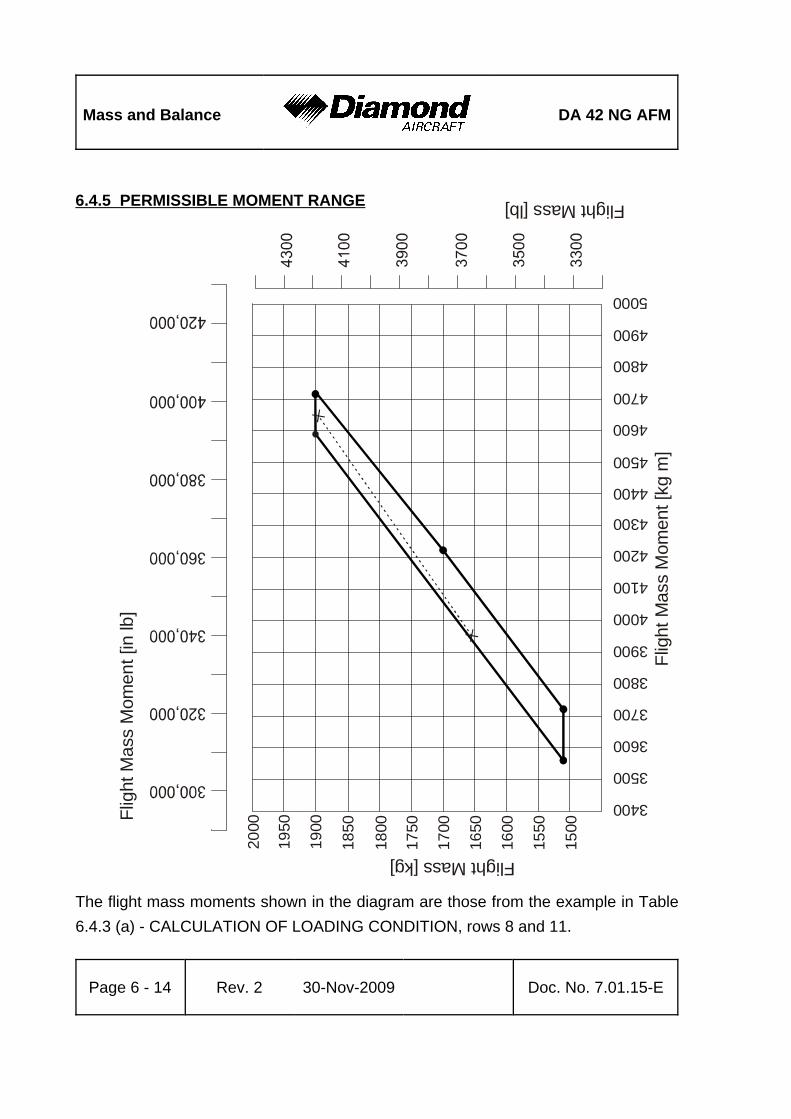
Mass and Balance DA 42 NG AFM
Page 6 - 14 Rev. 2 30-Nov-2009 Doc. No. 7.01.15-E
1500
1550
1600
1650
1700
1750
1800
Flight Mass [kg]
Flight Mass [lb]
Flig
ht M
ass
Mom
ent [
kg m
]
Flig
ht M
ass
Mom
ent [
in lb
]
1850
1900
4300
4400
4500
4200
4100
4000
3900
3800
3700
3600
3500
3400
4600
4700
4800
4900
5000
1950
2000
6.4.5 PERMISSIBLE MOMENT RANGE
The flight mass moments shown in the diagram are those from the example in Table6.4.3 (a) - CALCULATION OF LOADING CONDITION, rows 8 and 11.

DA 42 NG AFM Mass and Balance
Doc. No. 7.01.15-E Rev. 2 30-Nov-2009 Page 6 - 15
6.5 EQUIPMENT LIST AND EQUIPMENT INVENTORY
All equipment that is approved for installation in the DA 42 NG is shown in the EquipmentList below.
NOTEThe equipment listed below cannot be installed in anyarbitrary combination. The airplane manufacturer must becontacted before removing or installing equipment, with theexception of replacing a unit by an identical unit.
The items of equipment installed in your particular airplane are indicated in the appropriatecolumn. The set of items marked as 'installed' constitutes the Equipment Inventory.

DA
42
NG
AFM
Mas
s an
d B
alan
ce
Doc
. No.
7.0
1.15
-ER
ev. 2
30-N
ov-2
009
Pag
e 6
- 16
Airp
lane S
erial
No.
:Re
gist
ratio
n:Da
te:
Mass
Leve
r Arm
Desc
riptio
nTy
pePa
rt No
.Ma
nufa
ctur
erS/
Nin
stall
edlb
kgin
mA
VIO
NIC
S C
OO
LIN
GAv
ionics
cooli
ng fa
nSA
FE 32
830
5 467
-00
Sand
ia Ae
rosp
ace
PFD
cooli
ng fa
nSA
FE 12
830
5 468
-00
Sand
ia Ae
rosp
ace
MFD
cooli
ng fa
nSA
FE 12
830
5 468
-00
Sand
ia Ae
rosp
ace
AU
TOPI
LOT
SYST
EMPi
tch se
rvoGS
A 81
011-
0087
8-00
Garm
inPi
tch se
rvo m
ount
GSM
8501
1-00
894-
07Ga
rmin
Roll s
ervo
GSA
8101
1-00
878-
00Ga
rmin
Roll s
ervo
mou
ntGS
M 85
011-
0089
4-07
Garm
inPi
tch tr
im se
rvoGS
A 81
011-
0087
8-00
Garm
inPi
tch tr
im se
rvo m
ount
GSM
8501
1-00
894-
04Ga
rmin
Yaw
servo
GSA
8001
1-00
877-
00Ga
rmin
Yaw
servo
mou
ntGS
M 85
011-
0089
4-08
Garm
inCo
ntrol
stick
DA4-
2213
-12-
90Di
amon
d Airc
raft
CWS
switc
h03
1-00
514-
0000
Bend
ix/Ki
ngAP
-Disc
switc
h03
1-00
428-
0000
Bend
ix/Ki
ngTr
im sw
itch a
ssy
200-
0918
7-00
00Be
ndix/
King
ELEC
TRIC
AL
POW
ERMa
in ba
ttery
RG24
-15(
M)Co
ncor
deEm
erge
ncy b
atter
yD6
0-25
60-9
1-00
Diam
ond A
ircra
ft

DA
42
NG
AFM
Mas
s an
d B
alan
ce
Airp
lane S
erial
No.
:Re
gist
ratio
n:Da
te:
Mass
Leve
r Arm
Desc
riptio
nTy
pePa
rt No
.Ma
nufa
ctur
erS/
Nin
stall
edlb
kgin
m
Doc
. No.
7.0
1.15
-ER
ev. 2
30-N
ov-2
009
Pag
e 6
- 17
ECU
back
up ba
ttery
LH (2
pcs.)
LC-R
127R
2PPa
naso
nicEC
U ba
ckup
batte
ry RH
(2 pc
s.)LC
-R12
7R2P
Pana
sonic
Exter
nal p
ower
conn
ector
DA4-
2443
-10-
00Di
amon
d Airc
raft
EQU
IPM
ENT
Safet
y belt
, pilo
t5-
01-()
Ser
ies5-
01-1
C071
0Sc
hroth
2.11
00.
960
92.5
202.
350
Safet
y belt
, co-
pilot
5-01
-() S
eries
5-01
-1C5
710
Schr
oth2.
110
0.96
092
.520
2.35
0Sa
fety b
elt, L
H pa
x5-
01-()
Ser
ies5-
01-1
B571
0Sc
hroth
2.25
01.
020
126.
800
3.22
0Sa
fety b
elt, R
H pa
x5-
01-()
Ser
ies5-
01-1
B071
0Sc
hroth
2.25
01.
020
126.
800
3.22
0Sa
fety b
elt, p
ilot
5-01
-() S
eries
5-01
-2G0
710
Schr
oth2.
110
0.96
092
.520
2.35
0Sa
fety b
elt, c
o-pil
ot5-
01-()
Ser
ies5-
01-2
G571
0Sc
hroth
2.11
00.
960
92.5
202.
350
Safet
y belt
, LH
pax
5-01
-() S
eries
5-01
-2H5
710
Schr
oth2.
250
1.02
012
6.80
03.
220
Safet
y belt
, RH
pax
5-01
-() S
eries
5-01
-2H0
710
Schr
oth2.
250
1.02
012
6.80
03.
220
Safet
y belt
, pilo
t5-
01-()
Ser
ies5-
01-2
G070
1Sc
hroth
2.11
00.
960
92.5
202.
350
Safet
y belt
, co-
pilot
5-01
-() S
eries
5-01
-2G5
701
Schr
oth2.
110
0.96
092
.520
2.35
0Sa
fety b
elt, L
H pa
x5-
01-()
Ser
ies5-
01-2
H570
1Sc
hroth
2.25
01.
020
126.
800
3.22
0Sa
fety b
elt, R
H pa
x5-
01-()
Ser
ies5-
01-2
H070
1Sc
hroth
2.25
01.
020
126.
800
3.22
0EL
T un
itME
406
453-
6603
Artex
2.06
4%
0.93
6%
179.
700
4.56
5EL
T re
mote
switc
h34
5-61
96-0
4Ar
texEL
T an
tenna
110-
338
Artex
0.47
00.
213
152.
800
3.88
0Bu
zzer
452-
6505
%Ar
tex

DA
42
NG
AFM
Mas
s an
d B
alan
ce
Airp
lane S
erial
No.
:Re
gist
ratio
n:Da
te:
Mass
Leve
r Arm
Desc
riptio
nTy
pePa
rt No
.Ma
nufa
ctur
erS/
Nin
stall
edlb
kgin
m
Doc
. No.
7.0
1.15
-ER
ev. 2
30-N
ov-2
009
Pag
e 6
- 18
SAFE
TY E
QU
IPM
ENT
Fire e
xting
uishe
rHA
L 1AI
R To
talFir
st aid
kit
FLIG
HT
CO
NTR
OLS
Flaps
actua
tor as
sy43
055
Krutz
Lift d
etecto
rC-
9970
1-1
Safe
Fligh
t Instr
.St
all w
arnin
g buz
zer
SC S
eries
SC 62
8 ND
Mallo
ryVa
riable
elev
ator s
topD6
4-27
33-1
2-00
Diam
ond A
ircra
ft
HYD
RA
ULI
CMo
tor pu
mp un
itX1
1-00
01-0
0-00
.00R0
Hydr
aulik
May
erHy
drau
lic flu
id tan
kX1
1-00
02-0
0-00
.00R0
Hydr
aulik
May
erHy
drau
lic co
ntrol
unit
X11-
0003
-00-
00.00
R0Hy
drau
lik M
ayer
High
pres
sure
filter
X11-
0004
-00-
00.00
R0Hy
drau
lik M
ayer
Hydr
aulic
pres
sure
accu
mulat
orX1
1-00
05-0
0-00
.00R0
Hydr
aulik
May
erML
G hy
drau
lic cy
linde
rX1
1-00
06-0
0-00
.00/1R
0Hy
drau
lik M
ayer
MLG
hydr
aulic
cylin
der
X11-
0006
-00-
00.00
/1R0
Hydr
aulik
May
erNL
G hy
drau
lic cy
linde
rX1
1-00
06-0
0-00
.00/2R
0Hy
drau
lik M
ayer
NLG
hydr
aulic
cylin
der
%%D6
0-90
29-0
3-01
_1%
Hydr
aulik
May
er%%%%%%%
Brak
e mas
ter cy
linde
r (2 p
cs.)
10-5
4ACl
evela
ndPa
rking
valve
60-5
BCl
evela
ndBr
ake a
ssem
bly30
-239
ACl
evela
nd

DA
42
NG
AFM
Mas
s an
d B
alan
ce
Airp
lane S
erial
No.
:Re
gist
ratio
n:Da
te:
Mass
Leve
r Arm
Desc
riptio
nTy
pePa
rt No
.Ma
nufa
ctur
erS/
Nin
stall
edlb
kgin
m
Doc
. No.
7.0
1.15
-ER
ev. 2
30-N
ov-2
009
Pag
e 6
- 19
IND
ICA
TIN
G /
REC
. SYS
TEM
Prim
ary f
light
displa
y (PF
D)GD
U 10
4001
1-00
972-
03Ga
rmin
6.40
02.
900
%70
.080
1.78
0Mu
lti fun
ction
disp
lay (M
FD)
GDU
1045
011-
0081
9-04
Garm
in6.
400
2.90
0%
70.0
801.
780
LAN
DIN
G G
EAR
Main
landin
g gea
r LH
D60-
3217
-11-
00Di
amon
d Airc
raft
Main
landin
g gea
r RH
D60-
3217
-12-
00Di
amon
d Airc
raft
Nose
land
ing ge
arD6
0-32
23-1
0-00
Diam
ond A
ircra
ftLD
G ge
ar w
arnin
gSC
Ser
iesSC
628 N
DPMa
llory
LIG
HTS
Map /
Rea
ding l
ight a
ssy c
rew
W14
61.0.
010
Rivo
ret
Cabin
Ligh
tW
1461
.0.01
0Ri
vore
tSt
robe
/ Pos
. ligh
t ass
y LH
A600
-PR-
D-28
01-0
7900
06-0
5W
helen
0.80
0%
0.36
3%
103.
800
2.63
8St
robe
/ Pos
. ligh
t ass
y RH
A600
-PG-
D-28
01-0
7900
06-0
7W
helen
0.80
0%
0.36
3%
103.
800
2.63
8St
robe
light
powe
r sup
ply LH
/RH
A490
ATS-
CF–1
4/28
01-0
7700
62-0
5W
helen
Taxi
light
Xeno
n D1S
Aero
Visi
on In
t.0.
990
0.44
979
.920
2.03
0Ta
xi lig
ht po
wer s
upply
XV1-
28Ae
ro V
ision
Int.
0.88
00.
400
82.2
902.
090
Land
ing lig
htXe
non D
1SAe
ro V
ision
Int.
0.99
00.
449
79.9
202.
030
Land
ing lig
ht po
wer s
upply
XV1-
28Ae
ro V
ision
Int.
0.88
00.
400
82.2
902.
090
Glar
eshie
ld lam
p ass
yDA
4-33
11-1
0-02
Diam
ond A
ircra
ftGl
ares
hield
light
inver
terAP
VL32
8-4-
1-L-
5QF
Quan
taflex
Plac
ards
inve
rter
APVL
328-
4-1-
L-15
QFQu
antaf
lex

DA
42
NG
AFM
Mas
s an
d B
alan
ce
Airp
lane S
erial
No.
:Re
gist
ratio
n:Da
te:
Mass
Leve
r Arm
Desc
riptio
nTy
pePa
rt No
.Ma
nufa
ctur
erS/
Nin
stall
edlb
kgin
m
Doc
. No.
7.0
1.15
-ER
ev. 2
30-N
ov-2
009
Pag
e 6
- 20
CO
MM
UN
ICA
TIO
N /
NA
VIG
ATI
ON
COMM
#1 an
tenna
DMC6
3-1/A
DM0.
400
0.18
017
7.10
04.
500
COMM
#2 an
tenna
DMC6
3-2
DM0.
400
0.18
015
5.10
03.
940
Audio
pane
l / Ma
rker /
ICS
GMA
1347
011-
0080
9-00
Garm
inHe
adse
t, pilo
tEc
helon
100
Telex
Head
set, p
ilot
HMEC
25-K
AP-2
025-
230-
715
Senn
heise
rHe
adse
t, co-
pilot
Eche
lon 10
0Te
lexHe
adse
t, co-
pilot
HMEC
25-K
AP-2
025-
230-
715
Senn
heise
rHe
adse
t, LH
pax
Eche
lon 10
0Te
lexHe
adse
t, LH
pax
HMEC
25-K
AP-2
025-
230-
715
Senn
heise
rHe
adse
t, RH
pax
Eche
lon 10
0Te
lexHe
adse
t, RH
pax
HMEC
25-K
AP-2
025-
230-
715
Senn
heise
rSp
eake
rFR
S8 / 4
Ohm
sVi
saton
Hand
mic
100 T
RA62
800-
001
Telex
Pitot
/ Stat
ic pr
obe,
heate
dAN
5814
-2PS
T-30
5Ae
roins
trume
ntsAl
terna
te sta
tic va
lveDA
4-31
11-5
1-00
Diam
ond A
ircra
ftBa
ckup
altim
eter
5934
PD-3
Unite
d Ins
trume
nts0.
496
0.22
570
.080
1.78
0Ba
ckup
altim
eter
LUN
1120
1120
.23B2
XMi
krotec
hna
Back
up ai
rspee
d ind
icator
8030
8030
-B.88
4Un
ited I
nstru
ments
0.68
00.
308
70.0
801.
780
Back
up ar
tificia
l hor
izon
4300
4300
-206
Mid C
ontin
ent In
str.
2.50
01.
134
%70
.080
1.78
0Ma
gneti
c com
pass
PG2C
-28V
SIRS
Nav
igatio
nOA
T pr
obe
GTP
5901
1-00
978-
00Ga
rmin
Digit
al air
data
syste
mGD
C74A
011-
0088
2-00
Garm
in1.
690
%0.
770
%70
.080
%1.
780
%
Digit
al air
data
syste
mGD
C 74
A01
1-00
882-
10%
Garm
in1.
690
%0.
770
%70
.080
%1.
780
%

DA
42
NG
AFM
Mas
s an
d B
alan
ce
Airp
lane S
erial
No.
:Re
gist
ratio
n:Da
te:
Mass
Leve
r Arm
Desc
riptio
nTy
pePa
rt No
.Ma
nufa
ctur
erS/
Nin
stall
edlb
kgin
m
Doc
. No.
7.0
1.15
-ER
ev. 2
30-N
ov-2
009
Pag
e 6
- 21
Integ
rated
avion
ics #1
GIA
63W
011-
0110
5-01
%Ga
rmin
5.29
02.
400
154.
900
3.93
5Int
egra
ted av
ionics
#2GI
A 63
W01
1-01
105-
01%
Garm
in5.
290
2.40
015
4.90
03.
935
Tran
spon
der
GTX
3301
1-00
779-
10Ga
rmin
3.10
0%
1.41
0%
153.
100
3.89
0At
titude
/ Hea
ding r
efere
nce s
ystem
GRS
7701
1-00
868-
10Ga
rmin
2.80
0%
1.27
0%
154.
900
3.93
5Ma
gneto
meter
GMU
4401
1-00
870-
00Ga
rmin
0.35
0%
0.16
0%
103.
800
2.63
8VO
R / L
OC / G
S an
tenna
CI 15
7PCo
mant
Dual
VOR
/ dua
l GS
duple
xer
CI 11
25Co
mant
LH: V
OR / L
OC / G
S an
tenna
CI
120-
1Co
mant
RH: V
OR / L
OC / G
S an
tenna
CI12
0-1
Coma
ntVO
R / L
OC / G
S PW
R co
mbine
rCI
120-
3Co
mant
Tran
spon
der a
ntenn
aKA
6107
1-00
221-
0010
Bend
ix/Ki
ngMa
rker a
ntenn
aCI
102
Coma
ntGP
S #1
anten
naGA
3601
3-00
244-
00Ga
rmin
0.47
0%
0.21
0%
104.
100
2.64
5GP
S #2
anten
naGA
3601
3-00
244-
00Ga
rmin
0.47
0%
0.21
0%
104.
100
2645
DME
KN 63
066-
1070
-01
Bend
ix/Ki
ng2.
800
%1.
270
%14
1.10
03.
580
DME
anten
naKA
6107
1-00
221-
0010
Bend
ix/Ki
ngAD
F re
ceive
rRA
3502
-(01)
0505
.757-
912
Beck
er2.
200
%1.
000
%15
5.50
03.
950
ADF
/ RMI
conv
erter
AC 35
04-(0
1)08
56.01
0-91
2Be
cker
1.65
0%
0.75
0%
165.
400
4.20
0AD
F an
tenna
AN 35
0008
32.60
1-91
2Be
cker
3.75
0%
1.70
0%
133.
900
3.40
0St
orms
cope
WX-
500
805-
1150
0-00
1L-
3 (Go
odric
h)2.
500
%1.
130
%14
0.10
03.
560
Stor
msco
pe an
tenna
NY-1
6380
5-10
930-
001
L-3 (
Good
rich)
0.84
0%
0.38
0%
280.
700
7.13
0TA
S pr
oces
sor
TAS
600
70-2
420-
x TAS
600
Avidy
ne/R
yan
TAS
proc
esso
rTA
S 61
070
-242
0-x T
AS61
0Av
idyne
/Rya
n6.
800
3.10
016
4.30
04.
175
TAS
proc
esso
rTA
S 62
070
-242
0-x T
AS62
0Av
idyne
/Rya
nTA
S pr
oces
sor
9900
BX70
-242
0-x
Avidy
ne/R
yan
Tran
spon
der c
ouple
r70
-204
0Av
idyne
/Rya
n0.
500
0.23
019
7.60
050
20

DA
42
NG
AFM
Mas
s an
d B
alan
ce
Airp
lane S
erial
No.
:Re
gist
ratio
n:Da
te:
Mass
Leve
r Arm
Desc
riptio
nTy
pePa
rt No
.Ma
nufa
ctur
erS/
Nin
stall
edlb
kgin
m
Doc
. No.
7.0
1.15
-ER
ev. 2
30-N
ov-2
009
Pag
e 6
- 22
TAS
anten
na, to
pS7
2-17
50-3
1LSe
nsor
Sys
tems
0.66
00.
298
164.
800
4.18
8TA
S an
tenna
, bott
omS7
2-17
50-3
2LSe
nsor
Sys
tems
0.75
00.
340
104.
300
2.65
0Da
ta lin
k pro
cess
orGD
L69A
011-
0098
7-00
Garm
in1.
860
%0.
840
%15
9.40
04.
050
GDL a
ntenn
aGA
3701
3-00
245-
00Ga
rmin
EMI fi
lter L
H%%
D64-
3454
-10-
00%
Diam
ond A
ircra
ft%%%%%%%
EMI fi
lter R
H%%
D64-
3454
-10-
00%
Diam
ond A
ircra
ft%%%%%%%
OXY
GEN
SYS
TEM
Oxyg
en cy
linde
r (em
pty)
1270
152-
2Ae
rox
7.40
03.
357
32.2
800.
820
Sing
le ou
tlet m
anifo
ld LH
4110
-401
-2Ae
rox
0.23
00.
104
69.6
901.
770
Sing
le ou
tlet m
anifo
ld RH
4110
-401
-2Ae
rox
0.23
00.
104
69.6
9017
70Du
al ou
tlet m
anifo
ld41
10-4
00-2
Aero
x0.
420
0.19
110
9.30
02.
775
Oxyg
en pr
essu
re re
gulat
or41
10-1
10Ae
rox
0.74
00.
336
21.2
600.
540
Fillin
g bloc
k41
10-4
05Ae
rox
0.54
00.
245
28.1
500.
715
Pres
sure
gaug
e41
10-4
90Ae
rox
0.11
00.
050
70.0
801.
780
ENG
INE
LH en
gine
E4-B
E4B-
00-0
00-0
00Au
stro E
ngine
RH en
gine
E4-B
E4B-
00-0
00-0
00Au
stro E
ngine
LH en
gine c
ontro
l unit
EECU
-E4-
01E4
A-92
-100
-000
%Is
s: 0
2()
%Au
stro E
ngine
RH en
gine c
ontro
l unit
EECU
-E4-
01E4
A-92
-100
-000
%Is
s: 0
2()
%Au
stro E
ngine
ECU
softw
are
Refer
to D
AI S
ervic
eBu
lletin
MSB
-42N
G-00
2Au
stro E
ngine

DA
42
NG
AFM
Mas
s an
d B
alan
ce
Airp
lane S
erial
No.
:Re
gist
ratio
n:Da
te:
Mass
Leve
r Arm
Desc
riptio
nTy
pePa
rt No
.Ma
nufa
ctur
erS/
Nin
stall
edlb
kgin
m
Doc
. No.
7.0
1.15
-ER
ev. 2
30-N
ov-2
009
Pag
e 6
- 23
EN
GIN
E S
TAR
TIN
GGl
ow pl
ug co
ntrol
unit L
H/RH
E4A-
94-2
00-0
00Au
stro E
ngine
Star
ter LH
/ RH
E4A-
93-0
00-0
00Au
stro E
ngine
ELE
CTR
ICA
L P
OW
ER
LH a
ltern
ator
E4A-
91-0
00-0
00Au
stro E
ngine
RH a
ltern
ator
E4A-
91-0
00-0
00Au
stro E
ngine
LH a
ltern
ator r
egula
torE4
A-91
-100
-000
Austr
o Eng
ineRH
alte
rnato
r reg
ulator
E4A-
91-1
00-0
00Au
stro E
ngine
EN
GIN
E F
UE
L P
UM
PS
LH fu
el pu
mps (
2x)
0-58
0-05
4-00
1Bo
sch
RH fu
el pu
mps (
2x)
0-58
0-05
4-00
1Bo
sch
EN
GIN
E F
IRE
WA
RN
ING
LH ov
erhe
at de
tector
X 20
03-2
Contr
ol Pr
oduc
ts, In
c.RH
over
heat
detec
torX
2003
-2Co
ntrol
Prod
ucts,
Inc.
EN
GIN
E IN
DIC
ATI
NG
Engin
e / A
irfram
e unit
GEA
7101
1-00
831-
00Ga
rmin

DA
42
NG
AFM
Mas
s an
d B
alan
ce
Airp
lane S
erial
No.
:Re
gist
ratio
n:Da
te:
Mass
Leve
r Arm
Desc
riptio
nTy
pePa
rt No
.Ma
nufa
ctur
erS/
Nin
stall
edlb
kgin
m
Doc
. No.
7.0
1.15
-ER
ev. 2
30-N
ov-2
009
Pag
e 6
- 24
PRO
PELL
ERPr
opell
er LH
MTV-
6-R-
C-F/
CF18
7-12
9mt
-pro
pelle
rPr
opell
er R
HMT
V-6-
R-C-
F/CF
187-
129
mt-p
rope
ller
Unfea
therin
g acc
umula
tor LH
X11-
0007
-00-
00Hy
drau
lik M
ayer
Unfea
therin
g acc
umula
tor R
HX1
1-00
07-0
0-00
Hydr
aulik
May
erUn
feathe
ring a
ccum
ulator
LHP-
893
mt-p
rope
ller
Unfea
therin
g acc
umula
tor R
HP-
893
mt-p
rope
ller
Gove
rnor
LHP-
877-
16mt
-pro
pelle
rGo
vern
or R
HP-
877-
16mt
-pro
pelle
r
FUEL
TA
NK
SYS
TEM
Fuel
prob
e ass
y., LH
inbo
ard
D60-
2817
-13-
00_1
Diam
ond A
ircra
ftFu
el pr
obe a
ssy.,
RH
inboa
rdD6
0-28
17-1
3-00
_1Di
amon
d Airc
raft
Fuel
prob
e ass
y., LH
outbo
ard
D60-
2817
-14-
00_1
Diam
ond A
ircra
ftFu
el pr
obe a
ssy.,
RH
outbo
ard
D60-
2817
-14-
00_1
Diam
ond A
ircra
ftAl
terna
te me
ans f
or fu
el qty
.D6
0-28
17-9
0-00
Diam
ond A
ircra
ft
AU
X FU
EL S
YSTE
MLH
auxil
iary f
uel p
ump
5100
-09
Duke
s1.
940
0.87
815
1.40
03.
846
RH au
xiliar
y fue
l pum
p51
00-0
9Du
kes
1.94
00.
878
151.
400
3846
LH ch
eck v
alve
%%X1
1-00
13-0
0-00
.00%
Hydr
aulik
May
er%%%%%%%
RH ch
eck v
alve
%%X1
1-00
13-0
0-00
.00%
Hydr
aulik
May
er%%%%%%%
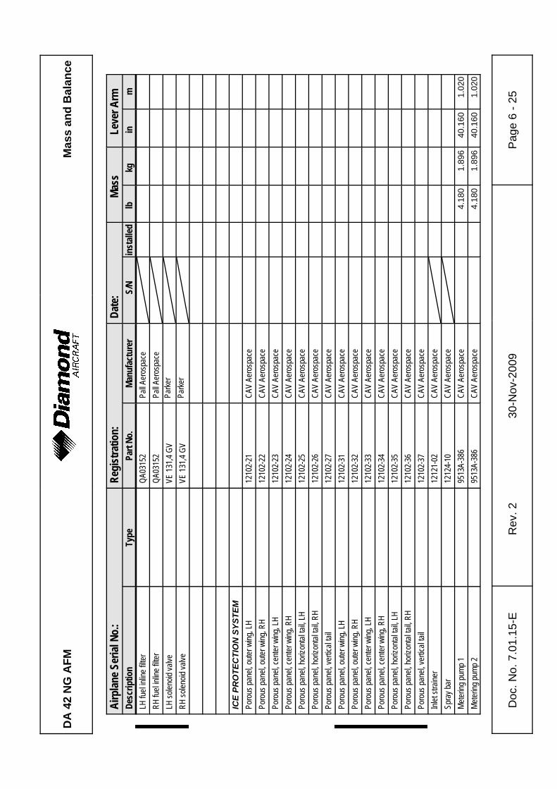
DA
42
NG
AFM
Mas
s an
d B
alan
ce
Airp
lane S
erial
No.
:Re
gist
ratio
n:Da
te:
Mass
Leve
r Arm
Desc
riptio
nTy
pePa
rt No
.Ma
nufa
ctur
erS/
Nin
stall
edlb
kgin
m
Doc
. No.
7.0
1.15
-ER
ev. 2
30-N
ov-2
009
Pag
e 6
- 25
LH fu
el inl
ine fil
ter%%
QA03
152
%Pa
ll Aer
ospa
ce%%%%%%%
RH fu
el inl
ine fil
ter%%
QA03
152
%Pa
ll Aer
ospa
ce%%%%%%%
LH so
lenoid
valve
%%VE
131,4
GV
%Pa
rker
% %%%%%%
RH so
lenoid
valve
%%VE
131,4
GV
%Pa
rker
% %%%%%%
ICE
PRO
TEC
TIO
N S
YSTE
MPo
rous
pane
l, oute
r wing
, LH
1210
2-21
CAV
Aero
spac
ePo
rous
pane
l, oute
r wing
, RH
1210
2-22
CAV
Aero
spac
ePo
rous
pane
l, cen
ter w
ing, L
H12
102-
23CA
V Ae
rosp
ace
Poro
us pa
nel, c
enter
wing
, RH
1210
2-24
CAV
Aero
spac
ePo
rous
pane
l, hor
izonta
l tail,
LH12
102-
25CA
V Ae
rosp
ace
Poro
us pa
nel, h
orizo
ntal ta
il, RH
1210
2-26
CAV
Aero
spac
ePo
rous
pane
l, ver
tical
tail
1210
2-27
CAV
Aero
spac
ePo
rous
pane
l, oute
r wing
, LH
%%12
102-
31%
CAV
Aero
spac
e%%%%%%%
Poro
us pa
nel, o
uter w
ing, R
H%%
1210
2-32
%CA
V Ae
rosp
ace
%%%%%%%
Poro
us pa
nel, c
enter
wing
, LH
%%12
102-
33%
CAV
Aero
spac
e%%%%%%%
Poro
us pa
nel, c
enter
wing
, RH
%%12
102-
34%
CAV
Aero
spac
e%%%%%%%
Poro
us pa
nel, h
orizo
ntal ta
il, LH
%%12
102-
35%
CAV
Aero
spac
e%%%%%%%
Poro
us pa
nel, h
orizo
ntal ta
il, RH
%%12
102-
36%
CAV
Aero
spac
e%%%%%%%
Poro
us pa
nel, v
ertic
al tai
l%%
1210
2-37
%CA
V Ae
rosp
ace
%%%%%%%
Inlet
strain
er12
121-
02CA
V Ae
rosp
ace
Spra
y bar
1212
4-10
CAV
Aero
spac
eMe
tering
pump
195
13A-
386
CAV
Aero
spac
e4.
180
1.89
640
.160
1.02
0Me
tering
pump
295
13A-
386
CAV
Aero
spac
e4.
180
1.89
640
.160
1.02
0

DA
42
NG
AFM
Mas
s an
d B
alan
ce
Airp
lane S
erial
No.
:Re
gist
ratio
n:Da
te:
Mass
Leve
r Arm
Desc
riptio
nTy
pePa
rt No
.Ma
nufa
ctur
erS/
Nin
stall
edlb
kgin
m
Doc
. No.
7.0
1.15
-ER
ev. 2
30-N
ov-2
009
Pag
e 6
- 26
De-ic
ing flu
id tan
kD6
0-30
13-2
4-50
Diam
ond A
ircra
ft8.
140
3.69
238
.390
0.97
5Mo
d filte
r ass
y 1D6
0-30
13-1
1-90
Diam
ond A
ircra
ft0.
680
0.30
840
.160
1.02
0Mo
d filte
r ass
y 2D6
0-30
13-1
1-90
Diam
ond A
ircra
ft0.
680
0.30
840
.160
1.02
0So
lenoid
valve
FV15
8H-2
8VCA
V Ae
rosp
ace
0.87
00.
395
40.1
6010
20So
lenoid
valve
FV15
8H-2
8VCA
V Ae
rosp
ace
0.87
00.
395
40.1
601.
020
High
pres
sure
switc
hP0
41ED
850
CAV
Aero
spac
ePr
opor
tionin
g unit
, nac
elle,
LHPU
300D
W14
2CA
V Ae
rosp
ace
Prop
ortio
ning u
nit, n
acell
e, RH
PU30
0DW
142
CAV
Aero
spac
eTa
il bra
cket
asse
mbly
1213
2-03
CAV
Aero
spac
e10
7048
527
8700
7080
Wind
shiel
d pum
p 1W
P209
ACA
V Ae
rosp
ace
650
295
4016
010
20W
indsh
ield p
ump 2
WP2
09A
CAV
Aero
spac
e65
029
540
160
1020
De-ic
e con
trol b
oxDA
I-903
0-00
-01
Diam
ond A
ircra
ft
AIR
PLA
NE
FLIG
HT
MA
NU
AL
Doc.
No. 7
.01.15
-EDi
amon
d Airc
raft
Plac
e: __
____
____
____
____
____
_Da
te: __
____
____
____
____
____
____
_Si
gnatu
re: _
____
____
____
____
____
____
____
_

DA 42 NG AFM Airplane Description
Doc. No. 7.01.15-E Rev. 2 30-Nov-2009 Page 7 - 1
CHAPTER 7DESCRIPTION OF THE AIRPLANE
AND ITS SYSTEMS
Page
7.1 INTRODUCTION . . . . . . . . . . . . . . . . . . . . . . . . . . . . . . . . . . . . . . . 7-37.2 AIRFRAME . . . . . . . . . . . . . . . . . . . . . . . . . . . . . . . . . . . . . . . . . . . . 7-37.3 FLIGHT CONTROLS . . . . . . . . . . . . . . . . . . . . . . . . . . . . . . . . . . . . 7-47.4 INSTRUMENT PANEL . . . . . . . . . . . . . . . . . . . . . . . . . . . . . . . . . . 7-117.5 LANDING GEAR . . . . . . . . . . . . . . . . . . . . . . . . . . . . . . . . . . . . . . . 7-147.6 SEATS AND SAFETY HARNESSES . . . . . . . . . . . . . . . . . . . . . . . 7-207.7 BAGGAGE COMPARTMENT . . . . . . . . . . . . . . . . . . . . . . . . . . . . . 7-227.8 CANOPY, REAR DOOR, AND CABIN INTERIOR . . . . . . . . . . . . . 7-227.9 POWER PLANT . . . . . . . . . . . . . . . . . . . . . . . . . . . . . . . . . . . . . . . 7-24
7.9.1 ENGINES, GENERAL . . . . . . . . . . . . . . . . . . . . . . . . . . . . . . 7-247.9.2 PROPELLER . . . . . . . . . . . . . . . . . . . . . . . . . . . . . . . . . . . . 7-257.9.3 OPERATING CONTROLS . . . . . . . . . . . . . . . . . . . . . . . . . . 7-287.9.4 ENGINE INSTRUMENTS . . . . . . . . . . . . . . . . . . . . . . . . . . . 7-327.9.5 FUEL SYSTEM . . . . . . . . . . . . . . . . . . . . . . . . . . . . . . . . . . . 7-347.9.6 COOLING SYSTEM . . . . . . . . . . . . . . . . . . . . . . . . . . . . . . . 7-457.9.7 OIL SYSTEMS . . . . . . . . . . . . . . . . . . . . . . . . . . . . . . . . . . . 7-467.9.8 TURBO-CHARGER SYSTEM . . . . . . . . . . . . . . . . . . . . . . . . 7-477.9.9 FIRE DETECTION SYSTEM . . . . . . . . . . . . . . . . . . . . . . . . 7-48
7.10 ELECTRICAL SYSTEM . . . . . . . . . . . . . . . . . . . . . . . . . . . . . . . . . 7-497.10.1 GENERAL . . . . . . . . . . . . . . . . . . . . . . . . . . . . . . . . . . . . . . 7-517.10.2 ELECTRICAL ENGINE CONTROL UNIT / ECU . . . . . . . . . 7-577.10.3 WARNING, CAUTION AND ADVISORY MESSAGES . . . . 7-59
7.11 PITOT-STATIC SYSTEM . . . . . . . . . . . . . . . . . . . . . . . . . . . . . . . . 7-65

Airplane Description DA 42 NG AFM
Page 7 - 2 Rev. 2 30-Nov-2009 Doc. No. 7.01.15-E
7.12 STALL WARNING SYSTEM . . . . . . . . . . . . . . . . . . . . . . . . . . . . . 7-657.13 GARMIN G1000 INTEGRATED AVIONICS SYSTEM . . . . . . . . . 7-66
7.13.1 GENERAL . . . . . . . . . . . . . . . . . . . . . . . . . . . . . . . . . . . . . 7-667.13.2 PRIMARY FLIGHT DISPLAY (PFD) . . . . . . . . . . . . . . . . . 7-677.13.3 MULTI-FUNCTION DISPLAY (MFD) . . . . . . . . . . . . . . . . . 7-697.13.4 AUDIO PANEL . . . . . . . . . . . . . . . . . . . . . . . . . . . . . . . . . 7-707.13.5 ATTITUDE AND HEADING REFERENCE SYSTEM (AHRS)
. . . . . . . . . . . . . . . . . . . . . . . . . . . . . . . . . . . . . . . . . . . . . . 7-707.13.6 AIR DATA COMPUTER (ADC) . . . . . . . . . . . . . . . . . . . . . 7-70
7.14 AVIONICS . . . . . . . . . . . . . . . . . . . . . . . . . . . . . . . . . . . . . . . . . . . 7-717.14.1 AUTOPILOT SYSTEM . . . . . . . . . . . . . . . . . . . . . . . . . . . 7-717.14.2 AUTOMATIC FLIGHT CONTROL SYSTEM ANNUNCIATIONS
AND ALERTS . . . . . . . . . . . . . . . . . . . . . . . . . . . . . . . . . . . 7-76

DA 42 NG AFM Airplane Description
Doc. No. 7.01.15-E Rev. 2 30-Nov-2009 Page 7 - 3
7.1 INTRODUCTION
Chapter 7 contains a description of the airplane and its systems, together with operatinginstructions.
For details about optional equipment see Chapter 9.
7.2 AIRFRAME
Fuselage
The CFRP fuselage is of semi monocoque molded construction. The center wing isattached to the fuselage with bolts. The two main spars and both nacelles are part of thecenter wing. The two main spars are CFRP items. The engine compartment in each nacelleis separated from the other structure with a firewall. The fire protection on the firewall isof a special fire-resistant matting, which is covered on the engine side by stainless steelcladding.
Wings
The wings have a front and rear spar; each wing has a top shell and a bottom shell; Thewhole wing is ‘fail-safe‘ design. The wings, as well as the ailerons and flaps, are madeof GFRP/CFRP, and are principally of sandwich construction. An aluminum fuel tank isinstalled in each of the wings.
Empennage
The airplane has a ‘T’ tail of GFRP/CFRP semi monocoque construction. Both thestabilizers have twin spars. Rudder and elevator are of sandwich construction.

Airplane Description DA 42 NG AFM
Page 7 - 4 Rev. 2 30-Nov-2009 Doc. No. 7.01.15-E
7.3 FLIGHT CONTROLS
The ailerons, elevator and wing flaps are operated through control rods, while the rudderis controlled by cables. The flaps are electrically operated. Elevator forces can be balancedby a trim tab on the elevator, which is operated by a Bowden cable. Rudder forces canbe balanced by a trim tab on the rudder, which is also operated by a Bowden cable.
Ailerons
Construction: GFRP/CFRP composite sandwich.
Hinges: There are 4 hinges, which are hinge pins mounted in an aluminumbracket. They are secured in position by a roll pin. The absence of thisroll pin can lead to the loss of the hinge pin and a consequent loss of flightsafety.
Operation: A rod end bearing is screwed into a steel push rod and locked by meansof a jam nut which has locking varnish applied to it. Damage to thisvarnish can indicate a twisting and thus a change to the adjustment. Theconnection between the rod end bearing and the control horn is a bolt,the nut of which is likewise sealed with locking varnish.
The aluminum control horn is attached to the aileron with 3 screws.

DA 42 NG AFM Airplane Description
Doc. No. 7.01.15-E Rev. 2 30-Nov-2009 Page 7 - 5
Flaps
The flaps are a two piece construction. The inner part of the flap is mounted to the centerwing and the outer part to the wing. Both parts are connected to each other with a formfit connection.
Construction: GFRP/CFRP composite sandwich.
Hinges: There are 6 hinges at the outer part and 4 hinges at the inner part of theflap. These hinges are hinge pins mounted in an aluminum bracket. Theyare secured in position by a roll pin. The absence of this roll pin can leadto the loss of the hinge pin and a consequent loss of flight safety.
Operation: Each part is connected with a flap control horn to the push rods of theflap control system. A rod end bearing is screwed into a steel push rodand locked by means of a jam nut which has locking varnish applied toit. Damage to this varnish can indicate a twisting and thus a change tothe adjustment. The connection between the rod end bearing and thecontrol horn is a bolt, the nut of which is likewise sealed with lockingvarnish.
Each flap control horn is attached to the flap part with 3 screws.
The flaps are driven by an electric motor and have 3 settings:
- Cruise (UP), totally retracted
- Approach (APP), and
- Landing (LDG).

Airplane Description DA 42 NG AFM
Page 7 - 6 Rev. 2 30-Nov-2009 Doc. No. 7.01.15-E
The flaps are operated by means of a 3-position flap selector switch on the instrumentpanel. The positions of the switch correspond to the positions of the flaps, the Cruiseposition of the switch being at the top. If the switch is moved to another position, the flapscontinue to travel automatically until they have reached the position selected on the switch.The UP and LDG positions are additionally protected by a limit switch to guard againstover-running the end positions.
The electrical flap drive has an automatic circuit breaker which can also be operatedmanually.
Flap Position Indicator:
The current flap position is indicated by means of three lights beside the flap selectorswitch.
When the upper light (green) is illuminated, the flaps are in the Cruise position (UP);
when the center light (white) is illuminated, the flaps are in Approach position (APP);
when the lower light (white) is illuminated, the flaps are in Landing position (LDG).
When two lights are illuminated simultaneously, the flaps are between the two indicatedpositions. This is the case only when the flaps are in transition.

DA 42 NG AFM Airplane Description
Doc. No. 7.01.15-E Rev. 2 30-Nov-2009 Page 7 - 7
Elevator
Construction: GFRP sandwich.
Hinges: 5 hinges.
Operation: Steel pushrods;
Two of the bellcrank bearings are accessible for visual inspection nextto the lower hinge of the rudder. The elevator horn and its bearing, aswell as the connection to the pushrod, can be visually inspected at theupper end of the rudder.
Variable Elevator Stop:
The DA 42 NG is equipped with an electrically operated actuator that limits the elevator-uptravel to 13° as soon as the power setting of both engines exceeds approximately 20 %(approach power setting). This is 2.5° less than the 15.5° full deflection.
The linear actuator acts as a movable stop and is controlled by two switches, one for eachpower lever. When the power of one engine is reduced below approximately 20 % fullelevator deflection is regained.
An amber annunciation (CAUTION) on the G1000 display is provided to inform the pilotin case a malfunction occurs. The annunciation illuminates when the variable stop shouldbe in place and is actually not activated (power on condition) or should be retracted andactually limits the elevator travel (power off condition).

Airplane Description DA 42 NG AFM
Page 7 - 8 Rev. 2 30-Nov-2009 Doc. No. 7.01.15-E
Rudder
Construction: GFRP sandwich.
Hinges: Upper hinge: One bolt.
Lower hinge: Bearing bracket including rudder stops, held by 4 screwsto the rear web of the vertical stabilizer. The mating part on the rudderis a bracket which is attached to the rudder by 2 bolts. The bolts and nutsare accessible to visual inspection.
Operation: Steel cables, the eyes of which are connected to the bolts on the bracket.

DA 42 NG AFM Airplane Description
Doc. No. 7.01.15-E Rev. 2 30-Nov-2009 Page 7 - 9
Elevator Trim
The trim control is a black wheel in the center console to the rear of the power lever. Toguard against overrotating, the trim wheel incorporates a friction device. A mark on thewheel shows the take-off (T/O) position.
Turn wheel to the front = nose down
Turn wheel to the rear = nose up
Rudder Trim
The trim control is a black wheel in the center console below the instrument panel. A markon the wheel shows the center position and the direction of movement.
Turn wheel to the right = right turnTurn wheel to the left = left turn
Pedal Adjustment
NOTEThe pedals may only be adjusted on the ground!
The pedals are unlocked by pulling the black handle which is located behind the rearattachment.
Forward Adjustment:
Whilst keeping the handle pulled, push the pedals forward with your feet. Release thehandle and allow the pedals to lock into place.
Rearward Adjustment:
Using the unlocking handle, pull the pedals back to the desired position. Release thehandle and push the pedals forward with your feet until they lock into place.

Airplane Description DA 42 NG AFM
Page 7 - 10 Rev. 2 30-Nov-2009 Doc. No. 7.01.15-E
Electrical Pedal Adjustment (Optional Equipment, OÄM 42-070)
NOTEThe pedals may only be adjusted on the ground!
The pedals are adjusted using a rocker switch, located on the rear wall of the leg room.The related circuit breaker is located below the switch.
Forward Adjustment:
To move the pedals forward, depress lower side of switch. When pedals are in correctposition, release switch.
Rearward Adjustment:
To move the pedals in the rearward direction, depress upper side of switch. When pedalsare in correct position, release switch.
Locking:
Upon release the switch moves automatically to the ‘power off’ position, so locking thepedals in the present position.

DA 42 NG AFM Airplane Description
Doc. No. 7.01.15-E Rev. 2 30-Nov-2009 Page 7 - 11
7.4 INSTRUMENT PANEL

Airplane Description DA 42 NG AFM
Page 7 - 12 Rev. 2 30-Nov-2009 Doc. No. 7.01.15-E
Major instruments and controls
1 Electric master switch 17 Circuit breakers*2 Avionic master switch 18 Backup airspeed indicator3 Engine master switches 19 Backup artificial horizon4 Start switch 20 Backup altimeter5 Pitot-/Stall warning heat switch 21 Emergency compass6 Alternator switches 22 ELT control unit7 ECU test buttons 23 Primary flight display (PFD)8 VOTER switches 24 Audio amplifier / intercom / marker
beacon receiver9 Rotary buttons for instrument
lighting and flood light25 Multi function display (MFD)
10 Light switches 26 De-ice control panel11 Emergency switch 27 Autopilot control unit (part of MFD)12 Flap selector switch 28 Alt air lever13 Landing gear switch 29 Landing gear emergency
extension lever14 Alternate static valve 30 Oxygen pressure indicator15 Microphone socket 31 Oxygen control knob16 Ventilation nozzles 32 Fuel pump switches
*) Designations and abbreviations used to identify the circuit breakers are explained inSection 1.5 - DEFINITIONS AND ABBREVIATIONS.
NOTEThe figure on previous page shows the typical DA 42 NGinstallation position for the equipment. The actual installationmay vary due to the approved equipment version.

DA 42 NG AFM Airplane Description
Doc. No. 7.01.15-E Rev. 2 30-Nov-2009 Page 7 - 13
Cockpit Ventilation
Ventilation in the front is provided by spherical ventilation nozzles (16) in the instrumentpanel. Furthermore there are spherical nozzles in the roll bar on the left and right sidenext to the front seats as well as on the central console above the passengers’ heads.The spherical nozzles are opened and closed by twisting.

Airplane Description DA 42 NG AFM
Page 7 - 14 Rev. 2 30-Nov-2009 Doc. No. 7.01.15-E
7.5 LANDING GEAR
The landing gear is a fully retractable, hydraulically operated, tricycle landing gear. Strutsfor the landing gear are air oil assemblies.
The hydraulic pressure for the landing gear operation is provided by an electrically poweredhydraulic pump, which is activated by a pressure switch, when the required pressure istoo low. Electrically actuated hydraulic valves, which are operated with the gear selectorswitch, provide the required hydraulic pressure for the movement of the landing gear.The gear selector switch is located on the instrument panel. The switch must be pulledout before it is moved to UP or DOWN position. Gear extension normally takes 6-10seconds.
When the landing gear is retracted, the main wheels retract inboard into the center wingand the nose wheel retracts forward into the nose section. Hydraulic pressure on theactuators keeps the landing gear in the retracted position. A pressurized gas containeracts as an accumulator which keeps the system pressure constant by replacing the volumelost due to the normal actuator leakages. This prevents a permanent starting of thehydraulic pump in flight.
Springs assist the hydraulic system in gear extension and locking the gear in the downposition. After the gears are down and the downlock hooks engage, springs maintain forceon each hook to keep it locked until it is released by hydraulic pressure.
The three green lights directly next to the landing gear operating switch illuminate toindicate that each gear is in the correct position and locked. If the gear is in neither thefull up nor the full down position, a red warning light on the instrument panel illuminates.
Should one power lever be placed in a position below 25% while the landing gear isretracted, a warning horn sounds to alert the pilot that the gear is retracted. Additionally,a CHECK GEAR caution is indicated on the PFD. The same warning appears if the flapsmove into position LDG (fully extended) while the gear is retracted.

DA 42 NG AFM Airplane Description
Doc. No. 7.01.15-E Rev. 2 30-Nov-2009 Page 7 - 15
To test the gear warning system (refer to 4A.6.1 - PRE-FLIGHT INSPECTION) push thetest button close by the gear selector switch. The aural gear alert should appear.
CAUTIONIf the aural alert does not appear, an unscheduledmaintenance is necessary.
To prevent inadvertent gear retraction on ground, an electric squat switch prevents thehydraulic valve from switching if the master switch is on and the gear extension switchis placed in the UP position.
After take-off, the gear should be retracted before an airspeed of 152 KIAS is exceeded.The landing gear may be extended at any speed up to 188 KIAS.
The landing gear is designed to be manually operated in the event of failure. Since thegear is held in the retracted position by hydraulic pressure, gravity will allow the gear toextend if the system fails for any reason. To extend and lock the gears in the event offailure, it is only necessary to relieve the hydraulic pressure by means of the emergencygear extension lever, which is located under the instrument panel to the left of the centerconsole. Pulling this lever releases the hydraulic pressure and allows the gear to fall free.Before pulling the emergency gear extension lever, place the gear selector switch in theDOWN position.
NOTEIf the emergency gear extension has been pulled due to anemergency, the system has to be checked before pushingthe lever in again.
The nose gear is steerable by the use of full rudder pedal travel. A gear damping element,incorporated in the nose gear steering system, prevents shimmy tendencies. When thegear is retracted, the nose wheel centers as it enters the wheel well, and the steeringlinkage disengages to reduce pedal loads in flight.

Airplane Description DA 42 NG AFM
Page 7 - 16 Rev. 2 30-Nov-2009 Doc. No. 7.01.15-E
Hydraulic Gear Extension System Schematic
The main landing gear of the DA 42 NG is extended with three hydraulic cylinders. Thefollowing schematic figures show the system conditions for each operating mode.In figure 1 the extension of the landing gear is shown. To reduce the amount of pumpedhydraulic fluid during this operation, the return flow is partly led into the feeding flow ofthe system.
The figure below shows the system status when the landing gear is extended. All hydrauliccylinders are under high pressure.

DA 42 NG AFM Airplane Description
Doc. No. 7.01.15-E Rev. 2 30-Nov-2009 Page 7 - 17
The operating mode for the retraction of the landing gear is shown in the next figure. Whileenergizing the right hydraulic valve, the fluid flow in the hydraulic system is started dueto different piston areas of the landing gear cylinders although the pressure on both sidesof the system is equal.
While the landing gear is retracted both valves are energized and excessive hydraulicfluid on one side is drained into the tank. This configuration of the system is shown in thefollowing figure.

Airplane Description DA 42 NG AFM
Page 7 - 18 Rev. 2 30-Nov-2009 Doc. No. 7.01.15-E
For an emergency extension of the landing gear, the hydraulic fluid can pass through anemergency extension valve so that the gear is extended by gravity. The condition of thesystem is shown in the figure below.

DA 42 NG AFM Airplane Description
Doc. No. 7.01.15-E Rev. 2 30-Nov-2009 Page 7 - 19
brake pedals,pilot
brake pedals,co-pilot
parking brakevalve
brake cylinder, LH brake cylinder, RH
Wheel Brakes
Hydraulically operated disk brakes act on the wheels of the main landing gear. The wheelbrakes are individually operated by means of toe pedals.
Parking Brake
The lever is located on the small center console under the instrument panel and is in theupper position when the brakes are released. To operate the parking brake, pull the leverdownwards until it catches. Brake pressure is built up by multiple operation of the toe brakepedals, and is maintained until the parking brake is released. To release, the lever ispushed upwards.

Airplane Description DA 42 NG AFM
Page 7 - 20 Rev. 2 30-Nov-2009 Doc. No. 7.01.15-E
7.6 SEATS AND SAFETY HARNESSES
To increase passive safety, the seats are constructed using a carbon fiber/Kevlar hybridmaterial and GFRP. The seats are removable to allow maintenance and inspection ofthe underlying controls. Covers on the control sticks prevent loose objects from fallinginto the area of the controls.
The seats have removable furnishings and are equipped with energy-absorbing foamelements.
The seats are fitted with three-part safety harnesses. The harnesses are fastened byinserting the end of the belts in the belt lock, and are opened by pressing the red releaseon the belt lock.
The backs of the rear seats can be laid forward after pulling upwards on the locking boltknob.
If front seats with adjustable backrests are installed (OÄM 42-067), the angle of thebackrests can be adjusted for best comfort. The backrest lever is situated on the outboardside of the backrest. However, during take-off, landing and emergency landing thebackrests must be fixed in the upright position designated by a placard on the roll-overbar.
CAUTIONBefore the backrest lever is lifted in order to unlock thebackrest, lean back towards the backrest to counteract thespring load; otherwise the backrest may snap forward.
CAUTIONDo not apply a load of more than 90 daN (202 lbf) to the topof the backrest. Damage to the adjustment mechanism mayotherwise result.

DA 42 NG AFM Airplane Description
Doc. No. 7.01.15-E Rev. 2 30-Nov-2009 Page 7 - 21
Outboard Hinge
Inboard Hinge
Lamella Package
Friction AdjustmentScrew
Seat Lever
Lumbar Support Lever
Lumbar Support
For adjustment lift the backrest lever and bend forward or backward to the desired backrestangle. Then lift the backrest lever fully, release and press down to set the friction lock.
In case of a defective adjustment mechanism the outboard friction adjustment screw canbe tightened with a 10 mm hexagon nut in clockwise direction in order to fix the backrestin the upright position.
If possible, set the backrest lever to the locked position. The mechanism must be repairedat the next scheduled inspection.
The lumbar support can be adjusted by operating the lumbar support lever mounted onthe outboard side of the seat pan.
If seats with adjustable backrests are installed (OÄM 42-067):

Airplane Description DA 42 NG AFM
Page 7 - 22 Rev. 2 30-Nov-2009 Doc. No. 7.01.15-E
7.7 BAGGAGE COMPARTMENT
There are two baggage compartments. One is located in the nose section and it isaccessible through two compartment doors.
The other baggage compartment is behind the seat backs of the rear seats. Baggagemay be loaded there provided it is restrained by means of a baggage net.
7.8 CANOPY, REAR DOOR, AND CABIN INTERIOR
Front Canopy
The front canopy is closed by pulling down on the canopy frame, following which it is lockedby means of a handle on the left hand side of the frame. On locking, steel bolts lock intomating holes in polyethylene blocks.
"Cooling gap" position: a second setting allows the bolts to lock in, leaving a gap underthe forward canopy.
The canopy can be blocked by a locking device on the left side near the canopy openinglever by turning the key clockwise. The closed and blocked canopy can be opened frominside by pulling the lever inside the opening handle.
WARNINGThe airplane may be operated with the front canopy in the“cooling gap” position on the ground only. Before take-off thefront canopy must be completely closed and locked.
Do not block the front canopy with the locking key before flightin order to assure emergency evacuation from outside.
A window on the left and right hand side of the canopy can be opened for additionalventilation or as an emergency window.

DA 42 NG AFM Airplane Description
Doc. No. 7.01.15-E Rev. 2 30-Nov-2009 Page 7 - 23
Rear Door
The rear door is closed in the same way, by pulling down on the frame and locking it withthe handle. A gas pressure damper prevents the door from dropping; in strong winds theassembly must be securely held. The rear door is protected against unintentional openingby an additional lever.
The door can be blocked by a locking device on the left side near the door opening leverby turning the key clockwise. The closed and blocked door can be opened from insideby pulling the lever inside the opening handle.
WARNINGDo not block the door with the locking key before flight inorder to assure emergency access from outside.
Heating and Ventilation
Heating and ventilation are operated using two levers located on the small center consoleunder the instrument panel.
Right lever: up = HEATING ON (seats, floor)down = HEATING OFF
Center lever : up = DEFROST ON (airflow to canopy)down = DEFROST OFF
The heat of the RH engine is used for the front seats and floor, the heat of the LH engineis used to defrost the canopy.
The air inlet for the ventilation system is placed on the underside of the RH wing, inboardof the engine nacelle. The air is distributed within the cabin via 6 nozzles (2 on theinstrument panel LH/RH side, 2 on the overhead panel and 2 on the LH/RH side of thepassenger compartment). The jet direction of each cone can be changed easily andthe jet intensity can be regulated by rotation of the nozzle.
Airplane Description DA 42 NG AFM
Page 7 - 24 Rev. 2 30-Nov-2009 Doc. No. 7.01.15-E
7.9 POWER PLANT
7.9.1 ENGINES, GENERAL
There are two Austro Engine E4-B engines installed, which have the followingspecifications:
- Liquid-cooled four-cylinder four-stroke engine with wet sump lubrication- Inline construction- Common rail direct injection- Propeller speed reducing gear 1:1.69- Digital engine control with integrated propeller governor (separate oil system)- Turbo charger with intercooler
Displacement:
Max. power: 123.5 kW (165.6 DIN-HP) at 2300 RPM at sea level and ISA
Max. continuous power: 113.6 kW (152.3 DIN-HP) at 2100 RPM at sea level and ISA
The indications for monitoring important engine parameters during operation are integratedwithin the Garmin G1000 display. Each engine can only be operated with the ENGINEMASTER switch ON. Each engine has an own ECU (Electrical Engine Control Unit) whichreceives its electrical power from the generator when at least one engine is running. Whenboth engines are at standstill, the ECU receives its electrical power from the battery.

DA 42 NG AFM Airplane Description
Doc. No. 7.01.15-E Rev. 2 30-Nov-2009 Page 7 - 25
7.9.2 PROPELLER
Two mt-Propeller MTV-6-R-C-F / CF 187-129 hydraulically regulated 3-bladed constantspeed feathering propellers are installed. Each propeller has wood composite blades withfiber-reinforced plastic coating and stainless steel edge cladding; in the region of thepropeller hub the leading edge is coated with adhesive PU foil. These blades combinethe lowest weight whilst minimizing vibration.
Propeller Control
The propeller pitch control system consists of the P-877-16 mt-Propeller governor valve.The pitch is set by the ECU via an electro-mechanical actuator on the governor. To changethe blade pitch angle gearbox oil is pumped into the propeller hub. Increasing the oilpressure leads to a decrease of pitch and a higher RPM. Decreasing the pressure leadsto higher pitch and a lower RPM.
Depending on the power setting the propeller pitch is adjusted such that the required RPMwill be obtained as shown in the following diagram.

Airplane Description DA 42 NG AFM
Page 7 - 26 Rev. 2 30-Nov-2009 Doc. No. 7.01.15-E
Pressure Accumulator:
The pressure accumulator is a nitrogen oil type. It is connected to the gearbox oil circuitvia an electric valve at the accumulator, which is operated with the ENGINE MASTERswitch.
When the ENGINE MASTER switch is set to ON the valve is opened. When the engineis running, the accumulator is filled with oil at a pressure of approximately 22 bar (320 psi).During engine operation the accumulator makes sure that enough oil pressure is availableeven if the oil feed by the gearbox oil pump is decreasing due to negative acceleration.The hydraulic pressure keeps the propeller pitch angle below the start lock position, ormoves the propeller blades beyond the start lock position.
Feathering:
To feather the propeller the engine must be shut down with the appropriate ENGINEMASTER switch. This will open the electric governor valve. All oil will flow back from thepropeller hub, allowing the blades to move into the feathered pitch position. At the sametime the electric valve at the pressure accumulator closes, and the oil pressure is restoredin the accumulator.
Feathering is only possible at propeller speeds above 1300 RPM.
CAUTIONIf the engine is shut down below an RPM of 1300 the propellerpitch remains below the start lock position. In this case thespeed must be increased to increase the propeller RPM.

DA 42 NG AFM Airplane Description
Doc. No. 7.01.15-E Rev. 2 30-Nov-2009 Page 7 - 27
Unfeathering:
To unfeather the propeller, the associated ENGINE MASTER switch must be set to ON.This will open the electric valve at the pressure accumulator. The pressure stored in theaccumulator will move the propeller blades into a low pitch position. As soon as thepropeller starts turning and the gearbox oil operates, the accumulator will be refilled.
Ground Operation:
CAUTIONOperation on the ground at high RPM should be avoided asfar as possible, as the blades could suffer stone damage. Forthis reason a suitable site for engine runs should be selected,where there are no loose stones or similar items.
WARNINGNever move the propeller by hand.

Airplane Description DA 42 NG AFM
Page 7 - 28 Rev. 2 30-Nov-2009 Doc. No. 7.01.15-E
7.9.3 OPERATING CONTROLS
Power Lever
Engine performance is controlled by a power lever for each engine. Both power leversare situated on the large center console. ‘Front’ and ‘rear’ are defined in relation to thedirection of flight.
Each power lever is used to set the desired engine power LOAD (%)
Lever forward (MAX) = Full power
Lever to rear (IDLE) = Idle
A separate ECU for each engine controls manifold pressure, injected fuel quantity andpropeller speed according to the desired engine power preselected with the power lever.If the power lever is in a low power position - as for a landing approach - while the landinggear is retracted, an aural warning alerts the pilot to the retracted landing gear. Additionally,a CHECK GEAR caution is indicated on the PFD.
A propeller governor, which is controlled by the ECU, is flanged onto the front of eachengine. The propeller governor oil circuit is supplied with oil by the gearbox oil pump (alsosee Section 7.9.2 - PROPELLER). A loss of oil pressure leads to a feathering of thepropeller blades, thus allowing continuation of the flight according to 3.11.3 - DEFECTIVEPROPELLER RPM REGULATING SYSTEM.
CAUTIONFollowing governor failure the RPM should be adjusted usingthe power lever. Every effort should be made not to exceed2300 RPM.

DA 42 NG AFM Airplane Description
Doc. No. 7.01.15-E Rev. 2 30-Nov-2009 Page 7 - 29
CAUTIONThe power lever should be moved slowly, in order to avoidover-speeding and excessively rapid RPM changes. The lightwooden propeller blades produce more rapid RPM changesthan metal blades.
WARNINGIt is possible that the propeller blades remain in the positionof highest pitch in case of a malfunction of the engine controlunit. In this case the reduced engine performance should betaken into consideration.
ELECT. MASTER
The ELECT. MASTER switch has two positions:
OFF disconnecting battery power
ON connecting battery power to the power distribution system
ENGINE MASTER
Each engine can only be cranked with its ENGINE MASTER switched to ON. Whenactivated, the ENGINE MASTER provides the power supply for the preheat system, theunfeathering accumulator valve and the engine itself. To shut down the engine theappropriate ENGINE MASTER is switched to OFF.
START
Turning START key switch to the left starts the LH engine. Turning it to the right side startsthe RH engine.

Airplane Description DA 42 NG AFM
Page 7 - 30 Rev. 2 30-Nov-2009 Doc. No. 7.01.15-E
There are two VOTER switches, one for each engine. For normal operation both switchesare set to AUTO. Each engine is controlled by either ECU A or ECU B. In case of a failureof the active electrical engine control unit (ECU) there should be an automatic switch-overto the other ECU. If the automatic switch over fails, switch over can be done manuallyby switching to ECU A or ECU B. This procedure should only be applied in an emergency.
ECU TEST
There are two ECU TEST buttons, one for each engine. '
Power Lever at IDLE and RPM Below Approximately 900:
By pushing and holding the button until the end of the procedure, the self-test of eachengine control unit is started. The procedure is possible on the ground only. Otherwisethe test will not start. During the procedure the ECU performs a switch from ECU Ato ECU B or ECU B to ECU A, whichever is active at the moment, with the propellercycling. The propeller RPM is monitored automatically by the ECU. When switchingfrom one ECU to the other, a slight shake of the engine may occur. Finally the ECUswitches back. After that both caution lights must extinguish and the engine must run'
without a change.

DA 42 NG AFM Airplane Description
Doc. No. 7.01.15-E Rev. 2 30-Nov-2009 Page 7 - 31
Alternate Air
In the event of power loss because of icing or blocking of the air filter, there is thepossibility of drawing air from the engine compartment. The ALTERNATE AIR operatinglever which serves both engines simultaneously is located under the instrument panelto the right of the center console. To open the alternate air source the lever is pulled tothe rear. Normally, the alternate air source is closed with the lever in the forward position.
Placard on the lever, forward position:
ALTERNATE AIR
Placard on the lever, visible when lever is in the rearward position:
ALTERNATE AIR
ON
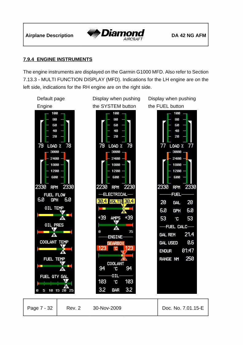
Airplane Description DA 42 NG AFM
Page 7 - 32 Rev. 2 30-Nov-2009 Doc. No. 7.01.15-E
7.9.4 ENGINE INSTRUMENTS
The engine instruments are displayed on the Garmin G1000 MFD. Also refer to Section7.13.3 - MULTI FUNCTION DISPLAY (MFD). Indications for the LH engine are on theleft side, indications for the RH engine are on the right side.
Default page Display when pushing Display when pushingEngine the SYSTEM button the FUEL button

DA 42 NG AFM Airplane Description
Doc. No. 7.01.15-E Rev. 2 30-Nov-2009 Page 7 - 33
NOTEThe figure on previous page is a general demonstration ofa typical G1000 MFD to show the different display modes.The pictured engine instrument markings may not stringentlyagree with the current engine limitations of the DA 42 NG.
NOTEThe fuel calculations on the FUEL CALC portion do not usethe airplane's fuel quantity indicators. The values shown arenumbers which are calculated from the last fuel quantityupdate done by the pilot and actual fuel flow data. Therefore,the endurance and range data is for information only, andmust not be used for flight planning.
Designation Indication Unit
LOAD % Available power %
RPM Propeller RPM 1/min
VOLTS Volts V
AMPS Ampères A
COOLANT TEMP Coolant temperature °C
GEARBOX Gearbox temperature °C
OIL TEMP Engine oil temperature °C
OIL PRES Oil pressure bar
FUEL QTY GAL Fuel quantity US gal
FUEL FLOW Fuel flow US gal/hr
FUEL TEMP Fuel temperature °C

Airplane Description DA 42 NG AFM
Page 7 - 34 Rev. 2 30-Nov-2009 Doc. No. 7.01.15-E
7.9.5 FUEL SYSTEM
General
'
'
'
'
'
'
'
'
'
'
'
'
'
'
'
'
'
'

DA 42 NG AFM Airplane Description
Doc. No. 7.01.15-E Rev. 2 30-Nov-2009 Page 7 - 35
Fuel is stored in the tanks which are located in the wings.
Normally fuel for the right engine is taken from the right wing main tank and for the leftengine from the left wing main tank.
On each engine fuel is injected with high pressure directly into the cylinders. The injectionnozzles (one per cylinder) are supplied with fuel by the common rail. Pressure inside therail is generated by a high pressure pump which receives fuel from two independent lowpressure fuel pumps. Both pumps are powered electrically. Depending on the powersetting the rail pressure is controlled by the ECU through an electric valve. Fuel that isnot injected is fed back into the appropriate wing tank.
Both sides of the fuel system are interconnected by crossfeed lines.
In each engine nacelle an auxiliary fuel tank may be installed.
Fuel Pumps
Each engine is feed by two parallel installed independent low pressure fuel pumps. Duringnormal operation one of the two fuel pumps is working. In case of a low fuel pressurefailure the ECU switches automatically to the second fuel pump. During landing andtake-off, or in case of a fuel pressure failure both fuel pumps can be activated by the FUELPUMP switch. If both fuel pumps are activated the fuel pressure increases.
WARNINGSwitching on the fuel pump in combination withCROSSFEED may cause damage to the high-pressurepump due to the high fuel pressure. After switching on thefuel pump in combination with CROSSFEED in case of anemergency special maintenance of the high pressurepump is required.
Each fuel pump is electrically connected to the LH/RH ECU BUS and protected by a 7.5 Acircuit breaker.

Airplane Description DA 42 NG AFM
Page 7 - 36 Rev. 2 30-Nov-2009 Doc. No. 7.01.15-E
NOTEBy switching between ECU A and B the two independentelectrical fuel pumps are switched over as well. In case ofan emergency both pumps can be activatedsimultaneously by using the fuel pump switch.
Fuel Selector Valves
For each engine one fuel selector valve is provided. The control levers for the fuel selectorvalves are situated on the center console behind the power levers. The positions are ON,CROSSFEED and OFF. During normal operation each engine takes the fuel from thetank on the same side as the engine. Before crossfeed operation check fuel pump is OFF.When CROSSFEED is selected, the engine will draw fuel from the tank on the oppositeside in order to extend range and keep fuel weight balanced during single engine operation.With the fuel selector valve both the feeding and the return line are switched.
The desired position is reached by pulling the lever back. To reach the OFF position asafety guard must be twisted. This is to ensure that this selection is not madeunintentionally.
NOTEIf one engine is inoperative the fuel selector valve for thisengine must be in the OFF position.
CAUTIONDo not operate with both fuel selector valves in crossfeedposition. Do not take-off with a fuel selector valve in crossfeedposition.

DA 42 NG AFM Airplane Description
Doc. No. 7.01.15-E Rev. 2 30-Nov-2009 Page 7 - 37
CAUTIONDo not shut down an engine with the fuel selector valve. Thehigh pressure fuel pump can be damaged.
CAUTIONSwitching on the fuel pump in combination with CROSSFEEDmay cause damage to the high-pressure pump.
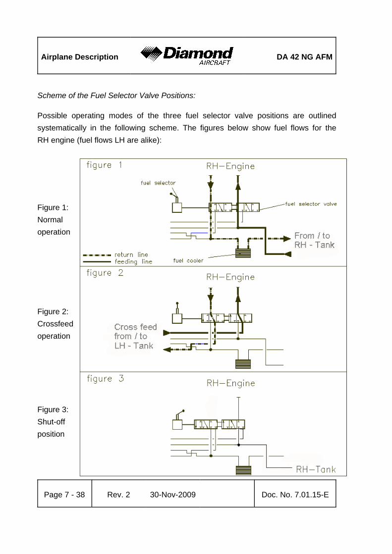
Airplane Description DA 42 NG AFM
Page 7 - 38 Rev. 2 30-Nov-2009 Doc. No. 7.01.15-E
Scheme of the Fuel Selector Valve Positions:
Possible operating modes of the three fuel selector valve positions are outlinedsystematically in the following scheme. The figures below show fuel flows for theRH engine (fuel flows LH are alike):
Figure 1:Normaloperation
Figure 2:Crossfeedoperation
Figure 3:Shut-offposition

DA 42 NG AFM Airplane Description
Doc. No. 7.01.15-E Rev. 2 30-Nov-2009 Page 7 - 39
With the LH fuel selector valve in crossfeed position, the fuel from the RH tank istransferred to the LH engine. Depending on the position of the RH fuel selector valve,the RH tank then feeds both engines (as shown in figure 4 below) or only the LH engine,when the fuel selector valve of the RH engine is in shut-off position (as shown in figure 5below).
Figure 4: Fuel selector valve RH normal operation position, fuelselector valve LH crossfeed position
Figure 5: Fuel selector RH valve shut-off position, fuel selector valveLH crossfeed position

Airplane Description DA 42 NG AFM
Page 7 - 40 Rev. 2 30-Nov-2009 Doc. No. 7.01.15-E
Main Fuel Tanks
Each tank consists of three aluminum chambers which are connected by a flexible hose.The tank is filled through a filler in the outboard fuel chamber. Only four liters (1 US gal)of fuel in each wing are unusable, so that a total quantity of 96 liters (25.4 US gal) in eachwing is usable.
There are two tank vents. One includes a check valve with a capillary and one includesa relief pressure valve, which operates at 150 mbar (2 psi) and allows fuel and air to flowto the outside with higher internal pressure. The relief pressure valve protects the tankagainst high pressure, if the tank was overfilled in case of an auxiliary fuel transfer failure.The check valve with capillary allows air to enter the tank but prevents flow of fuel to theoutside. The capillary equalizes the air pressure during climb. The hose terminals arelocated on the underside of the wing, approximately 2 meters (7 ft) from the wing tip.
In each tank a coarse filter (finger filter) is fitted before the outlet. To allow draining ofthe tank, there is an outlet valve at its lowest point.
At the lowest point in each side of the fuel system a fuel filter with a drain valve is installed.This drain valve can be used to remove water and sediment which has collected in thefuel system. The drain valves are fitted in each nacelle behind the firewall, approximately15 cm (0.56 ft) backward of the wing leading edge.
Fuel Quantity Indication
Two capacity probes measure the fuel quantity in each main tank. The indication isprovided by the G1000 flight display. Information about fuel consumption can be foundin Chapter 5 - PERFORMANCE.

DA 42 NG AFM Airplane Description
Doc. No. 7.01.15-E Rev. 2 30-Nov-2009 Page 7 - 41
Auxiliary Fuel Tanks (if installed)
The auxiliary fuel tanks are optional equipment (OÄM 42-056).
Description
The auxiliary fuel tanks are installed in the rear section of the engine nacelles, above thewing main spars. Each auxiliary fuel tank has a filler cap located on the top surface ofthe nacelle. The additional fuel capacity is 13.7 US gallons (52 liters) per side. The totalfuel capacity (main fuel tanks and auxiliary fuel tanks) is 39.7 US gallons (150.4 liters)per side.
The fuel supply connection attaches to a finger filter mounted at the rear of the auxiliaryfuel tank. Each auxiliary fuel tank has a auxiliary pump which transfers fuel into the relatedmain fuel tank.
The vent line for the auxiliary fuel tank has a check valve with capillary. It allows air toenter the tank but prevents flow of fuel to the outside. The capillary equalizes the airpressure during climb. A fuel drain valve is located at the rear of each auxiliary tank.
Operation
Two AUX PUMP switches in the cockpit are used to activate the auxiliary pumps. Theswitches are located behind the elevator trim wheel on the center console. Both switchesare intended to be used simultaneously to prevent the airplane from additional lateralimbalance. The auxiliary pump transfers the fuel from the auxiliary fuel tank into the relatedmain fuel tank. Fuel level switches shut off this pump automatically when the auxiliaryfuel tank is empty or when the main fuel tank is full. During operation of the pumps anadvisory alert on the Garmin G1000 indicates that the fuel transfer is in progress.
If the auxiliary fuel tank is empty, a caution alert appears on the Garmin G1000. In thiscase the auxiliary pumps must be switched OFF.

Airplane Description DA 42 NG AFM
Page 7 - 42 Rev. 2 30-Nov-2009 Doc. No. 7.01.15-E
When one auxiliary pump is defective, the fuel stored in the related auxiliary fuel tank isnot available. For use of the remaining fuel pump refer to to Section 4B.12 - L/R FUELTRANSFER FAIL. The flight plan must be amended accordingly.
The auxiliary pumps are electrically connected to the LH MAIN BUS and protected bya 5A circuit breaker, if no ice protection system (OÄM 42-053) is installed.
If the ice protection system is installed, both systems are protected by a 10 A circuitbreaker and an additional 7A fuse for the auxiliary pumps. The circuit breaker is labeledXFER PUMP/DE ICE.

DA 42 NG AFM Airplane Description
Doc. No. 7.01.15-E Rev. 2 30-Nov-2009 Page 7 - 43
Alternate Means for Fuel QuantityIndication for the Fuel Tank:
The alternate means for fuel quantityindication allows the fuel quantity in thetank to be determined during the preflightinspection. It functions according to theprinciple of communicating containers.The fuel quantity measuring device hasa recess which fits the airfoil of the wingin front of the fuel tank drain, which liesapproximately 10 cm (4 in) outboard ofthe engine nacelle. The metal connectoris pressed against the drain of the tank.The amount of fuel in the tank can nowbe read off from the vertical ascendingpipe.
For an exact indication the airplane muststand on level ground and the measuringdevice must be held vertically.
The designated location for the fuelquantity measuring device is a bag on therear side of the pilot seat.

Airplane Description DA 42 NG AFM
Page 7 - 44 Rev. 2 30-Nov-2009 Doc. No. 7.01.15-E
Fuel Temperature
Max. fuel temperature: 60 °C (140 °F)
Fuel Grade
Approved fuel grades are listed in Section 2.14 - FUEL.
NOTEIn order to provide information about the fuel grade it isrecommended to enter the fuel grade in the airplane logeach time fuel is refilled.

DA 42 NG AFM Airplane Description
Doc. No. 7.01.15-E Rev. 2 30-Nov-2009 Page 7 - 45
CoolantHeat
Exchanger
CoreEngine
ExpansionTank
Thermostatic Valve
Water Pump
CabinHeater
Pressure Relief Valve
7.9.6 COOLING SYSTEM
Each engine is liquid cooled. The liquid cooling system consists of a radiator (coolant heatexchange) and a bypass to this radiator. The bypass is in operation when coolanttemperatures are low. It therefore allows the engine to warm-up quickly. Upon reachinga certain temperature (approximately 88 °C or 190 °F) the radiator is activated by athermostat valve. Additionally a coolant to air heat exchanger is provided for the cabinheat system. The flow through the heat exchanger is independent of the coolanttemperature. An expansion tank helps to adjust the pressure in the system. The systemis protected against overpressure by means of a pressure relief valve.

Airplane Description DA 42 NG AFM
Page 7 - 46 Rev. 2 30-Nov-2009 Doc. No. 7.01.15-E
7.9.7 OIL SYSTEMS
Each engine has two separate oil systems.
Lubrication System (Engine and Turbo-Charger)
The engine lubrication is a wet sump lubrication system. The oil is cooled by awater/oil-cooler on the upperside of the engine.
A dip-stick is provided to check the oil quantity through an inspection hole in the leftcowling. If required, oil can also be filled in there (for approved oil grades refer to Section2.4 - POWER-PLANT LIMITATIONS).
Gearbox and Propeller Governor System
The second oil circuit lubricates the gearbox and serves the governor system and theregulation of the propeller.
The gearbox oil quantity can be checked with the help of an inspection glass which canbe reached through an inspection hole on the left side of the cowling.
CAUTIONIf the gearbox oil quantity is too low, an unscheduledmaintenance is necessary (for approved oil grades refer toSection 2.4 - POWER-PLANT LIMITATIONS).

DA 42 NG AFM Airplane Description
Doc. No. 7.01.15-E Rev. 2 30-Nov-2009 Page 7 - 47
engineair inlet
filter box
air filter
alternate air inletcharger
turbine
exhaust
waste gate
engine
intercooler
alternate air valve
7.9.8 TURBO-CHARGER SYSTEM
The exhaust system contains a manifold which collects exhaust gases from the outletsof the cylinders and feeds them to the turbine of the turbo charger. Behind the turbinethe exhaust gases are guided through the lower cowling to the exterior of the airplane.Excess exhaust gases bypass the turbine. The bypass is controlled by the ECU throughthe waste gate valve. A manifold pressure sensor behind the compressor allows the ECUto calculate the correct position of the waste gate valve. This prevents excessive manifoldpressures at low density altitudes. The intake air is compressed in the compressor whichis driven by the turbine, and is subsequently cooled down in the intercooler to increasepower. Cooling the air increases efficiency through the higher density of the cooler air.

Airplane Description DA 42 NG AFM
Page 7 - 48 Rev. 2 30-Nov-2009 Doc. No. 7.01.15-E
7.9.9 FIRE DETECTION SYSTEM
The fire detection system in the DA 42 NG consists of an overheat detector in the hotarea of each engine. In case of an increase of the engine compartment temperature above250 °C (480 °F) the overheat detector closes the electric circuit and a warning messageappears in the annunciation window of the G1000 PFD.
To test the fire detectors (refer to Section 4A.6.1 - PREFLIGHT INSPECTION) push thetest button located next to the gear selector switch. An aural alert and the fire warningmessage for the LH and RH engine should appear in the annunciation window of theG1000 PFD.
CAUTIONIf the warning does not appear, an unscheduled maintenanceis necessary.

DA 42 NG AFM Airplane Description
Doc. No. 7.01.15-E Rev. 2 30-Nov-2009 Page 7 - 49
7.10 ELECTRICAL SYSTEM
If MÄM 42-403 is not carried out:'

Airplane Description DA 42 NG AFM
Page 7 - 50 Rev. 2 30-Nov-2009 Doc. No. 7.01.15-E
If MÄM 42-403 is carried out:'
'
'
'
'
'
'
'
'
'
'
'
'
'
'
'
'
'
'
'

DA 42 NG AFM Airplane Description
Doc. No. 7.01.15-E Rev. 2 30-Nov-2009 Page 7 - 51
7.10.1 GENERAL
The DA 42 NG has 28 Volt DC system, which can be sub-divided into:
- Power generation- Storage- Distribution- Consumers
Power Generation
Power generation is provided by two 70 Ampère alternators (generators) which aremounted on the bottom left side of each engine. The alternators are driven by a flat belt.
The power output line of the left hand alternator is connected to the LH MAIN BUS viathe LH alternator relay and a 60 Ampère circuit breaker. The power output line of theRH alternator is connected to the RH MAIN BUS via the RH alternator relay and a 60Ampère circuit breaker. Both main busses are connected to the BATTERY BUS via a90 Ampère circuit breaker.
Both generator power output lines also run through a current sensor for each alternator,which provides an indication of the power being supplied to the electrical system by analternator including the current for battery charging on the G1000. In the event of a mainbattery failure the field of each alternator is energized by two 12 V, 7.2 Ah sealed leadacid batteries (ECU backup battery) connected in series, which are installed under thepassengers' seats. The ECU backup batteries provide also electrical power for the ECUfor a time of 30 minutes (condition).
The ENGINE MASTER LH (RH) switches connect the ECU backup battery to thealternator field via a 10 Ampère fuse.

Airplane Description DA 42 NG AFM
Page 7 - 52 Rev. 2 30-Nov-2009 Doc. No. 7.01.15-E
Alternator Control:
Each alternator has an alternator control unit. It measures the alternator output voltageand controls the current through the alternator field coils via a pulse-width modulatedsignal. To keep the output voltage stable in all load and speed situations, the alternatorfield signal is modulated accordingly.
The alternator control unit includes a comprehensive set of diagnostic functions that willwarn the operator using a caution message (L/R ALTN FAIL) on the G1000 PFD in caseof over- or undervoltage as well as a couple of other internal warning levels.
Storage
Main battery power is stored in a 24 V, 13.6 Ah lead-acid battery mounted on the right-aftside of the front baggage compartment. The main battery is connected to the HOTBATTERY BUS and to the BATTERY BUS via the 'battery'-relay which is installed in therelay junction box on the center-aft side of the front baggage compartment.
The battery relay is controlled with the ELECT. MASTER switch which is located on theleft-hand side of the instrument panel.
In addition, a non-rechargeable dry battery is installed as a further source of power forthe backup attitude gyro (artificial horizon) and the flood light. When the EMERGENCYswitch is set to ON, these two systems are supplied with power for at least 1.5 hours,independent of all other electrical consumers. During each 100 hour inspection, thisbattery is checked for proper functioning. Every 2 years or after use (broken seal on theswitch) the battery package must be replaced.

DA 42 NG AFM Airplane Description
Doc. No. 7.01.15-E Rev. 2 30-Nov-2009 Page 7 - 53
Distribution
Electrical power is distributed via the HOT BATTERY BUS, the BATTERY BUS, the LH(RH) ECU BUS, the LH (RH) MAIN BUS, and the AVIONIC BUS.
HOT BATTERY BUS:
The HOT BATTERY BUS is directly connected to the main battery and cannot bedisconnected from the main battery. The HOT BATTERY BUS provides power to thepilot map/reading light and ELT RCPI unit which are protected by there own fuses.
BATTERY BUS:
The BATTERY BUS is connected to the main battery via the battery relay which can becontrolled by the ELECT. MASTER switch. The BATTERY BUS provides power to theLH (RH) MAIN BUS and heavy duty power to both starters.
ECU BUS:
If MÄM 42-403 is not carried out:'
The LH (RH) ECU BUS is connected to the LH (RH) MAIN BUS via a diode andconnected to the power output line of the alternator via diode and a 30 Ampère circuitbreaker and provides power for the ECU A and ECU B via the LH (RH) ECU A (B)relays which are controlled by the LH (RH) ENGINE MASTER switch. The LH (RH)ENGINE MASTER switch must be set to ON to connect the ECU A and ECU B tothe ECU BUS.
If MÄM 42-403 is carried out:'
The LH (RH) ECU BUS is connected to the LH (RH) MAIN BUS via a diode and'
connected to the power output line of the alternator via diode and a 30 Ampère circuit'
breaker and provides power directly to ECU A and its fuel pump. ECU B and its fuel'
pump derive their electrical power from their associated ECU BUS via an additional'
diode and fuse.'

Airplane Description DA 42 NG AFM
Page 7 - 54 Rev. 2 30-Nov-2009 Doc. No. 7.01.15-E
Additionally, each ECU B and its fuel pump is supplied with electrical power from the'
opposite engine side ECU BUS via a diode and fuse.'
The LH (RH) ENGINE MASTER switch must be set to ON to activate the engine EECU.'
To support the alternator electrical power supply to the ECU’s in case of a malfunctionof the main battery, additional sealed-lead-acid batteries (ECU backup battery) areconnected to the RH and LH ECU bus.
These batteries are able to provide 30 minutes of engine operation in case of a completeairplane electrical failure. Both engines may stop if the 30 minutes have elapsed.
MAIN BUS:
The LH (RH) MAIN BUS is connected to the BATTERY BUS via a 90 Ampère circuitbreaker. The LH MAIN BUS provides power to the consumers directly connected to theLH MAIN BUS. The RH MAIN BUS provides power to the consumers directly connectedto the RH MAIN BUS and the AVIONIC BUS via the avionics master relay.
The AVIONIC MASTER switch must be set to ON to connect the RH MAIN BUS to theAVIONIC BUS.
Consumers
The individual consumers (e.g. radio, position lights, etc.) are connected to the appropriatebus via automatic circuit breakers.
Designations and abbreviations used to identify the circuit breakers are explained inSection 1.5 - DEFINITIONS AND ABBREVIATIONS.
Voltmeter
The voltmeter displays the voltage of the electrical system. Under normal operatingconditions the alternator voltage is shown, otherwise it displays the main battery voltage.

DA 42 NG AFM Airplane Description
Doc. No. 7.01.15-E Rev. 2 30-Nov-2009 Page 7 - 55
Ammeter
The ammeter displays the intensity of current which is supplied to the electrical systemby the LH (RH) alternator.
Landing and Taxi Lights
Landing and taxi lights are built into the wing center section, and are each operated bymeans of a switch (LANDING, TAXI) located on the row of switches on the instrumentpanel.
Position and Strobe Lights
Combined position and strobe lights (anti collision lights) are installed on both wing tips.Each system is operated by a switch (POSITION, STROBE) located on the row ofswitches on the instrument panel.
Flood Light
A two-dimensional light emitter is mounted above the instrument panel. It illuminates theinstrument panel as well as all levers, switches, etc. The flood light is switched on andits brightness is adjusted by means of a rotary button (FLOOD) in the LH section of theinstrument panel.
Instrument Lighting
With a rotary button (INSTRUMENT) in the LH section of the instrument panel the internallighting of the instruments is switched on and its brightness is adjusted.

Airplane Description DA 42 NG AFM
Page 7 - 56 Rev. 2 30-Nov-2009 Doc. No. 7.01.15-E
Pitot Heating
The Pitot probe, which provides measurement for the Pitot-static system, is electricallyheated. The heating is activated with a switch (PITOT HEAT) located on the row ofswitches on the instrument panel. The temperature is automatically kept constant bymeans of a thermal switch on the Pitot probe, and as an additional safety measure athermal fuse is built in. If this thermal fuse is activated, the Pitot heating can no longerbe switched on, and the PITOT FAIL will be displayed. In this case the system shouldbe serviced. The PITOT HT OFF is on if the Pitot heating is switched off.
External Power Socket
The DA 42 NG has an external 28 Volt DC power socket located on the lower surfaceof the fuselage nose section. When external power is connected, the control relay isenergized and the external power comes online.
The socket itself has three pins:
• a large negative pin
• a large positive pin
• a small positive pin
A diode protects the system from reverse polarity.

DA 42 NG AFM Airplane Description
Doc. No. 7.01.15-E Rev. 2 30-Nov-2009 Page 7 - 57
7.10.2 ELECTRICAL ENGINE CONTROL UNIT / ECU
Engine Control and Regulation
The Electrical ECU is used to control the engine actuators (e.g. fuel injectors)according to the engine sensor information. The ECU monitors, controls andregulates all important parameters for engine operation.
Sensors installed are:
- Oil temperature (lubrication system engine) / OIL TEMP- Oil pressure (lubrication system engine) / OIL PRES
- Coolant temperature / COOLANT TEMP- Gearbox temperature / GEARBOX- Camshaft RPM (twice)- Crankshaft RPM (twice)- Fuel pressure in the common rail- Manifold pressure- Manifold air temperature- Ambient air pressure- Propeller governor / oil pressure- Power lever position (twice)- Voltage- Starter switch signal- Fuel pressure- VOTER switch signal- ECU TEST switch signal
Airplane Description DA 42 NG AFM
Page 7 - 58 Rev. 2 30-Nov-2009 Doc. No. 7.01.15-E
In accordance with the received signals and a comparison with the programmedcharacteristic diagrams the necessary inputs are calculated and transmitted by thefollowing signal lines to the engine:
- Signal for propeller governor pressure valve- Signal for the rail-pressure regulation valve- Signal for each of the 4 injection nozzles - Activation of the glow plugs- Signal for the waste gate valve
The following alerts are displayed on PFD of the G1000:
- Glow sparks active- Status ECU A- Status ECU B
The Electrical ECU consists of two similar ECUs. A VOTER switch is integrated inthe Electrical ECU and proposes an ECU to control the engine regarding the ECUoperating hours or in case of a failure the ECU with better engine control capability.
A fault in one of the ECUs is indicated by a caution message on the PFD(L/R ECU A/B FAIL). After the indication of the L/R ECU A/B FAIL caution message,the engine must be serviced.
DA 42 NG AFM Airplane Description
Doc. No. 7.01.15-E Rev. 2 30-Nov-2009 Page 7 - 59
7.10.3 WARNING, CAUTION AND ADVISORY MESSAGES
Crew Alerting System (CAS)
The G1000 crew alerting system (CAS) is designed to provide visual and aural alertsto the flight crew. Alerts are divided into three levels as follows:
WARNING
CAUTION
ADVISORY
Crew alerts will appear in the alerts window on the PFD. In this window warnings willappear at the top, followed by cautions and advisories, respectively. Within the criticalitylevels, messages will appear from newest (top) to oldest (bottom).
At the low right corner of the display there is a MSG (message) soft key. The MSG keyprovides two functions in the CAS:
1. Pressing the MSG key acknowledges a new master warning / caution / advisoryindication.
2. An additional MSG key press with no master alert indication active will open apop-up auxiliary flight display (AFD) page that contains information for all activealerts.
This structure allows the crew to scroll through all system alerts if the alerts windowoverflows. This approach displays the most critical alerts close to the pilot´s primary fieldof view at all times, with the option of allowing lower criticality alerts to overflow and beaccessible from the pop-up AFD page/window.

Airplane Description DA 42 NG AFM
Page 7 - 60 Rev. 2 30-Nov-2009 Doc. No. 7.01.15-E
Alert Levels
Level Text Color Importance Audible Tone
Warning Red May requireimmediate
corrective action
Warning chimetone which repeatswithout delay untilacknowledged bythe crew
Caution Amber May require futurecorrective action
Single warningchime tone
AnnunciationAdvisory White None
Message Advisory White None
Safe OperationAnnunciation Green Lowest None

DA 42 NG AFM Airplane Description
Doc. No. 7.01.15-E Rev. 2 30-Nov-2009 Page 7 - 61
Warning Alerts on the G1000
Warning alerts Meaning / Cause
L/R ENG TEMP The annunciation is active when the engine coolant temperatureis greater than 105 °C.
L/R OIL TEMP The annunciation is active when the engine oil temperature isgreater than 140 °C.
L/R OIL PRES The annunciation is active when the engine oil pressure isless than 1.5 bar.
L/R FUEL TEMP The annunciation is active when the fuel temperature isgreater than 60 °C.
L/R GBOX TEMP The annunciation is active when the gearbox oil temperature isgreater than 120 °C.
L/R FUEL PRES The annunciation is active when the engine fuel pressure islow.
L/R ALTN AMPS The annunciation is active when the alternator load is greater than70 amps.
L/R ENG FIRE The annunciation is active when an engine fire is detected.
L/R STARTER This annunciation is used to indicate to the pilot that the starteris engaged when it should not be.
DOOR OPEN The annunciation is used to indicate to the pilot if the baggage-,canopy- or rear door is open.
POSN ERROR The annunciation is active when the G1000 will no longerprovide GPS based navigational guidance.
ATTITUDE FAIL The annunciation is active when the display system is notreceiving attitude reference information from the AHRS.
AIRSPEED FAIL The annunciation is active when the display system is notreceiving airspeed input from the air data computer.
ALTITUDE FAIL The annunciation is active when the display system is notreceiving altitude input from the air data computer.

Airplane Description DA 42 NG AFM
Warning alerts Meaning / Cause
Page 7 - 62 Rev. 2 30-Nov-2009 Doc. No. 7.01.15-E
VERT SPEEDFAIL
The annunciation is active when the display system is notreceiving vertical speed input from the air data computer.
HDG The annunciation is active when the display system is notreceiving valid heading input from the AHRS.
WARN This annunciation constitutes a RAIM position warning. Thenav deviation bar is removed.
Audible Warning Alerts
Warning alerts Meaning / Cause
Landing gearretracted
A warning chime tone which repeats without delay is activewhen the landing gear is retracted while the flaps move intothe LDG position or when the POWER lever is placed in aposition below 25 %.

DA 42 NG AFM Airplane Description
Doc. No. 7.01.15-E Rev. 2 30-Nov-2009 Page 7 - 63
Caution Alerts on the G1000
Caution alerts Meaning / Cause
L/R ECU A FAIL
or
L/R ECU B FAIL
The annunciation is active when a fault in ECU A or ECU Bhas occurred.
In case of minor faults, the annunciation can be reset once bypressing the ECU TEST button for more than 2 seconds.However, the annunciation will re-appear upon the nextattempt to start the engine.
L/R FUEL LOW The annunciation is active when the fuel quantity is below4 ± 1 US gal usable fuel.
L/R VOLTS LOW The annunciation is active when bus voltage is less than25 Volts.
L/R ALTN FAIL The annunciation is active when the alternator has failed.
L/R COOL LVL The annunciation is active when engine coolant level is low.
PITOT FAIL The annunciation is active when the Pitot heater is failed.
PITOT HT OFF The annunciation is active when the Pitot heat is off.
STAL HT FAIL The annunciation is active when the stall heater is failed.
STAL HT OFF The annunciation is active when the stall heater is off.
STICK LIMIT Control stick limiting system (variable elevator stop) hasfailed.
L/R AUX FUEL E
This annunciation can only occur when the auxiliary fuel tanksystem (optional equipment) is installed.
The annunciation is active when the L/R auxiliary fuel tank isempty and the AUX PUMP is ON.
INTEG RAIM notavailable
The annunciation is active when RAIM (ReceiverAutonomous Integrity Monitor) is not available.
AHRS ALIGN:Keep Wings Level
The annunciation is active when the AHRS (Attitude andHeading Reference System) is aligning.
CHECK GEAR Landing gear is not down and locked.

Airplane Description DA 42 NG AFM
Caution alerts Meaning / Cause
Page 7 - 64 Rev. 2 30-Nov-2009 Doc. No. 7.01.15-E
DEICE LVL LO De-icing fluid level is low (if installed).
DEICE PRES HI De-icing pressure is high (if installed).
DEICE PRES LO De-icing pressure is low (if installed).
Annunciation Advisory Alerts on the G1000
Advisory alerts Meaning / Cause
L/R GLOW ON The annunciation is active when the glow plugs are powered.
L/R AUXPUMPON
The annunciation is active when fuel transfer from auxiliary tomain tank is in progress (if installed).
Message Advisory Alerts on the G1000
Advisory alerts Meaning / Cause
PFD FAN FAIL The annunciation is active when the PFD fan is inoperative.
MFD FAN FAIL The annunciation is active when the MFD fan is inoperative.
GIA FAN FAIL The annunciation is active when the GIA fan is inoperative.

DA 42 NG AFM Airplane Description
Doc. No. 7.01.15-E Rev. 2 30-Nov-2009 Page 7 - 65
7.11 PITOT-STATIC SYSTEM
Total pressure is measured at the leading edge of a Pitot probe under the left wing. Thestatic pressure is measured through the static ports in the rear fuselage. To protect againstdirt and condensation there are filters in the system. The Pitot probe is electrically heated.
With the alternate static valve, the static pressure in the cabin can be used as staticpressure source in the event of a failure of the Pitot-static system.
7.12 STALL WARNING SYSTEM
The lift detector of the DA 42 NG is located on the front edge of the left wing below thewing chord line. It is supplied electrically and provides a stall warning, before the angleof attack becomes critical. The stall status is announced to the pilot by a continuous soundin the cockpit.
The lift detector vane, the mounting plate and the complete housing are heated to preventicing. Heating is engaged together with the Pitot heating.

Airplane Description DA 42 NG AFM
Page 7 - 66 Rev. 2 30-Nov-2009 Doc. No. 7.01.15-E
7.13 GARMIN G1000 INTEGRATED AVIONICS SYSTEM
7.13.1 GENERAL
The Gamin G1000 is a fully integrated flight, engine, communication, navigation andsurveillance instrumentation system. This integrated avionics system consists of a primaryflight display (PFD), a multi-function display (MFD), an audio panel, an attitude andheading reference system (AHRS), an air data computer (ADC) and the sensors andcomputers to process flight and engine information for display to the pilot. The systemcontains dual GPS receivers, dual VOR/ILS receivers, dual VHF communicationstransceivers, a transponder, and an integrated annunciation system to alert the pilot ofcertain abnormal conditions.
A remote avionic box is located behind the aft baggage compartment frame. A push-to-talk(PTT) button for the COM portion of the G1000 is mounted on the end of each controlstick. There are connection facilities for up to 4 headsets between the front seats.
Refer to the Garmin G1000 Cockpit Reference Guide, P/N 190-00963-00 and GarminG1000 Pilot's Guide for the Diamond DA 42 NG, P/N 190-00962-00 for completedescriptions of the G1000 system and operating procedures.
NOTENear the DME ground station, it can happen under certainadverse conditions that the Bendix/King KN 63 DME losesthe direct signal from the ground station and locks onto an"echo". This will result in an inaccurate indication of thedistance.
NOTEDuring retraction and extension of the landing gear theADF-indication may be inaccurate.

DA 42 NG AFM Airplane Description
Doc. No. 7.01.15-E Rev. 2 30-Nov-2009 Page 7 - 67
7.13.2 PRIMARY FLIGHT DISPLAY (PFD)
The primary flight display (PFD; see figure below) typically displays airspeed, attitude,altitude, and heading information in a traditional format. Slip information is shown as atrapezoid under the bank pointer. One width of the trapezoid is equal to a one ball widthslip. Rate of turn information is shown on the scale above the compass rose; full scaledeflection is equal to a standard rate turn. The following controls are available on thePFD (clockwise from top right):
* Communications frequency volume and squelch knob* Communications frequency set knobs* Communications frequency transfer button* Altimeter setting knob (baro set)* Course knob* Map range knob and cursor control* FMS control buttons and knob* PFD softkey buttons, including master warning/caution acknowledgment* Altitude reference set knob* Heading bug control* Navigation frequency transfer button* Navigation frequency set knobs* Navigation frequency volume and identifier knob

Airplane Description DA 42 NG AFM
Page 7 - 68 Rev. 2 30-Nov-2009 Doc. No. 7.01.15-E
The PFD displays the crew alerting (annunciator) system. When a warning or cautionmessage is received, a warning or caution annunciator will flash on the PFD, accompaniedby an aural tone. A warning is accompanied by a repeating tone, and a caution isaccompanied by a single tone. Acknowledging the alert will cancel the flashing and providea text description of the message. Refer to Chapter 3 - EMERGENCY PROCEDURES,Chapter 4B - ABNORMAL OPERATING PROCEDURES, and Section 7.10.3 - WARNING,CAUTION AND ADVISORY MESSAGES.

DA 42 NG AFM Airplane Description
Doc. No. 7.01.15-E Rev. 2 30-Nov-2009 Page 7 - 69
Advisory messages related to G1000 system status are shown in white and areaccompanied by a white flashing ADVISORY alert. Refer to the G1000 Pilot's Guide andCockpit Reference Guide for descriptions of the messages and recommended actions(if applicable).
Trend vectors are shown on the airspeed and altimeter displays as a magenta linepredicting 6 seconds at the current rate. The turn rate indicator also functions as a trendindicator on the compass scale.
The PFD can be displayed in a composite format for emergency use by pressing theDISPLAY BACKUP button on the audio panel. In the composite mode, the full crewalerting function remains, but no map functions are available.
7.13.3 MULTI-FUNCTION DISPLAY (MFD)
The multi-function display (MFD) typically displays engine data, maps, terrain, traffic andtopography displays, and flight planning and progress information. The display unit is,nearly identical to the PFD and contains the same controls as previously listed.Additionally the MFD incorporates the controls for the autopilot system.
Engine instruments are displayed on the MFD. Discrete engine sensor information isprocessed by the Garmin engine airframe (GEA) sub-system. When an engine sensorindicates a value outside the normal operating range, the legend will turn yellow for cautionrange, and turn red and flash for warning range.
Also refer to Section 7.9.4 - ENGINE INSTRUMENTS.
Airplane Description DA 42 NG AFM
Page 7 - 70 Rev. 2 30-Nov-2009 Doc. No. 7.01.15-E
7.13.4 AUDIO PANEL
The audio panel contains traditional transmitter and receiver selectors, as well as anintegral intercom and marker beacon system. The marker beacon lights appear on thePFD. In addition, a clearance recorder records the last 2 ½ minutes of received audio.Lights above the selections indicate what selections are active. Pressing the red DISPLAYBACKUP button on the audio panel causes both the PFD and MFD to display a compositemode.
7.13.5 ATTITUDE AND HEADING REFERENCE SYSTEM (AHRS)
The attitude and heading reference system (AHRS) uses GPS, rate sensors, air data,and magnetic variation to determine pitch and roll attitude, sideslip and heading. Operationis possible in a degraded mode if the system loses any of these inputs. Status messagesalert the crew of the loss of any of these inputs. The AHRS will align while the airplaneis in motion, but will align quicker if the wings are kept level during the alignment process.
7.13.6 AIR DATA COMPUTER (ADC)
The air data computer (ADC) provides airspeed, altitude, vertical speed, and airtemperature to the display system. In addition to the primary displays, this informationis used by the FMS and TIS systems.

DA 42 NG AFM Airplane Description
Doc. No. 7.01.15-E Rev. 2 30-Nov-2009 Page 7 - 71
7.14 AVIONICS
7.14.1 AUTOPILOT SYSTEM
General
The GFC 700 automatic flight control system (AFCS) is a 3 axis autopilot and flight directorsystem which provides the pilot with the following features: altitude preselect and altitudehold (ALT); yaw damper; flight level change with airspeed hold (FLC); vertical speed hold(VS); navigation tracking for VOR (NAV) and GPS (GPS); heading hold (HDG); approachmode and go around (GA) pitch/roll guidance. The system consists of autopilot controlson the multi-function display (MFD), servos with autopilot processing logic, flight directorprocessing logic in the GIAs, a control stick-mounted elevator trim switch, a control stickmounted trim interrupt and autopilot disconnect switch, a control stick mounted CWS(control wheel steering) switch, a power lever mounted GA (go-around) switch, andPFD/MFD-mounted altitude preselect, heading, and course knobs.
The GFC 700 autopilot contains an electric pitch trim system which is used by the autopilotfor automatic pitch trim during autopilot operation and by the pilot for manual electric pitchtrim when the autopilot is not engaged. The manual electric pitch trim is operated by asplit switch on the pilot's control stick.
The GFC 700 autopilot and manual electric trim (MET) will not operate until the systemhas satisfactorily completed a preflight test. The preflight test begins automatically withinitial power application to the autopilot (AVIONIC MASTER switch is set to the ONposition).
The following conditions will cause the autopilot to automatically disconnect:
- Electrical power failure- Internal autopilot system failure- AHRS malfunction- Loss of air data computer information

Airplane Description DA 42 NG AFM
Page 7 - 72 Rev. 2 30-Nov-2009 Doc. No. 7.01.15-E
The GFC 700 may be manually disconnected by any of the following means:
- Depressing the red AP DISC button on the pilot's or co-pilot's control stick- Moving the left (outboard) side of the manual electric trim switch on the pilot's
control stick- Pushing the AP button on the autopilot mode controller when the autopilot is
engaged- Depressing the GA button on the left side of the power lever- Pulling the AUTOPILOT circuit breaker- Turning off the AVIONICS MASTER switch- Turning off the ELECT. MASTER switch
In addition, the CWS (control wheel steering) switch on the pilot's control stick willdisconnect the autopilot servos from the airplane flight controls as long as the CWS switchis depressed.
Power to the GFC 700 autopilot and electric trim system is supplied through the AVIONICMASTER switch and the AUTOPILOT circuit breaker. The AVIONIC MASTER switchcan be used as an additional means to disable the autopilot and electric trim system.The red AP DISC switch on the pilot's control stick will interrupt power to the manualelectric trim for as long as the switch is depressed.
Loss of instruments or components of the G1000 system will affect the GFC 700 AFCSas follows:
- Loss of the AHRS will cause the autopilot to disconnect. The autopilot and flightdirector will be inoperative. Manual electric trim will be available.
- Loss of the heading function of the AHRS will result in loss of the HDG mode.If in HDG mode at the time heading is lost, the autopilot will revert to basic rollmode (ROL).

DA 42 NG AFM Airplane Description
Doc. No. 7.01.15-E Rev. 2 30-Nov-2009 Page 7 - 73
- Loss of the MFD will not cause the autopilot to disconnect, and will remainengaged with limited functionality, but the autopilot cannot be re-engaged afterdisconnect by the pilot.
- Loss of the PFD will cause the autopilot to disconnect. The autopilot and flightdirector will be inoperative. Manual electric trim will be available.
- Loss of air data computer information will cause the autopilot to disconnect.The autopilot will be inoperative. The flight director will be available except forair data modes (ALT, VS, FLC). Manual electric trim is available.
- Loss of GIA #1 will cause the autopilot to disconnect. The autopilot, flightdirector and manual electric trim will be inoperative. Loss of GIA #2 will alsoprevent autopilot and manual electric trim operation, but flight director will beavailable.
- Loss of the standby airspeed indicator, standby attitude indicator, standbyaltimeter, or compass will have no effect on the autopilot.
- Loss of both GPS systems will cause the autopilot and flight director to operatein NAV modes (LOC, BC, VOR, VAPP) with reduced accuracy. Courseintercept and station crossing performance may be improved by executingintercepts and station crossings in HDG mode, then reselecting NAV mode.
The GFC 700 automatic flight control system (AFCS) installed in the Diamond DA 42 NGconsists of the following components:
- One GDU which contains the following mode control buttons:
AP (Autopilot engage/disengage)
FD (Flight director on/off)
HDG (Heading mode on/off)
NAV (Nav mode on/off)
APR (Approach mode on/off)
Airplane Description DA 42 NG AFM
Page 7 - 74 Rev. 2 30-Nov-2009 Doc. No. 7.01.15-E
ALT (Altitude hold mode on/off)
VS (Vertical speed mode on/off)
FLC (Flight level change mode on/off)
NOSE UP and NOSE DN (Vertical mode reference change)
YD (Yaw damper on/off)
This GDU is installed as the MFD.
- Servos with autopilot processing logic in the pitch, roll, yaw and pitch trim controlsystems
- Servo mounts and brackets
- Flight director processing logic in the GIAs
- Control stick-mounted manual electric trim (MET) switch (split switch) for pitch trim
- Control stick-mounted trim interrupt and autopilot disconnect switch
- Control stick-mounted CWS (control wheel steering) switch
- Remote-mounted go-around switch (on the left side of the power lever knob)
- PFD/MFD mounted altitude preselect knob (ALT)
- PFD/MFD mounted heading select knob (HDG)
Flight director commands and autopilot modes are displayed on the PFD. Full AFCSfunctionality is only available with both displays operating, and will disconnect undercertain reversionary conditions.
Upon initial system power-up, the system undergoes a preflight test. At the end of thetest, the autopilot disconnect tone sounds and the PFT and AFCS annunciations areremoved. Successful completion of the preflight test is required for the autopilot andmanual electric trim to engage.

DA 42 NG AFM Airplane Description
Doc. No. 7.01.15-E Rev. 2 30-Nov-2009 Page 7 - 75
Annunciation of the flight director and autopilot modes is shown in the lower status fieldof the PFD. In general, green indicates active modes and white indicates armed modes.When a mode is directly selected by the pilot, no flashing of the mode will occur. Whenautomatic mode changes occur, they will be annunciated with a flashing annunciationof the new mode for ten seconds in green. If a mode becomes unavailable for whateverreason, the mode will flash for ten seconds in yellow and be replaced by the new modein green.
Normal autopilot disconnects are annunciated with a yellow flashing AP on the PFDaccompanied by a two second autopilot disconnect tone. Normal disconnects are thoseinitiated by the pilot with the AP DISC switch, the MET switch, the AP button on the MFDmode controller, or the GA button. Abnormal disconnects will be accompanied by a redflashing AP on the PFD accompanied by a continuous autopilot disconnect tone. Thedisconnect tone and flashing alert may be cancelled by pressing the AP DISC switchor the left side of the MET switch.
Refer to the Garmin G1000 Cockpit Reference Guide, P/N 190-00963-00, and GarminG1000 Pilot's Guide for the Diamond DA 42 NG, P/N 190-00962-00, for completedescriptions of the G1000 system and operating procedures.
Power Supply
The AVIONIC MASTER switch supplies power to the avionics bus bar of the radio circuitbreakers and the autopilot circuit breaker.
The following circuit breaker is used to protect the following element of the GFC 700autopilot:
Circuit Breaker Function
AUTOPILOT Supplies power to the autopilot pitch, roll, yaw and pitch trimservos.

Airplane Description DA 42 NG AFM
Page 7 - 76 Rev. 2 30-Nov-2009 Doc. No. 7.01.15-E
7.14.2 AUTOMATIC FLIGHT CONTROL SYSTEM ANNUNCIATIONS ANDALERTS
Automatic Flight Control System (AFCS) Status Alerts
The following annunciations can appear on the PFD above the airspeed and attitudeindicators. Only one annunciation occurs at a time, and messages are priorized bycriticality.
Warning Alerts on the Automatic Flight Control System (AFCS)
Warning alerts Meaning / Cause
PFT PREFLIGHT TEST - Preflight system test failed; aural alert soundsat failure.
AFCSSYSTEM FAILURE - AP and MET are unavailable; FD may stillbe available.
PTCH PITCH FAILURE - Pitch axis control failure; AP inoperative.
ROL ROLL FAILURE - Roll axis control failure; AP inoperative.
YAW YAW DAMPER FAILURE - Yaw damper control failure; APinoperative.
PTRMPITCH TRIM FAILURE (or stuck AP TRIM switch) - if AP engaged,take control of the airplane and disengage AP. If AP disengaged,move AP TRIM switches separately to release.

DA 42 NG AFM Airplane Description
Doc. No. 7.01.15-E Rev. 2 30-Nov-2009 Page 7 - 77
Caution Alerts on the Automatic Flight Control System (AFCS)
Caution alerts Meaning / Cause
8ELE ELEVATOR MISTRIM UP - Pitch servo providing sustainedforce in the indicated direction.
9ELE ELEVATOR MISTRIM DOWN - Pitch servo providing sustainedforce in the indicated direction.
7AIL AILERON MISTRIM LEFT - Roll servo providing sustainedforce in indicated direction.
AIL6 AILERON MISTRIM RIGHT - Roll servo providing sustainedforce in indicated direction.
7RUD RUDDER MISTRIM LEFT - Yaw servo providing sustainedforce in the indicated direction.
RUD6 RUDDER MISTRIM RIGHT - Yaw servo providing sustained forcein the indicated direction.
Advisory Alerts on the Automatic Flight Control System (AFCS)
Advisory alerts Meaning / Cause
PFT
PREFLIGHT TEST - Performing preflight system test; auralalert sounds at completion. Do not press the AP DISC switchduring servo power-up and preflight system tests as this maycause the preflight system test to fail or never to start (if servosfail their power-up tests). Power must be cycled to the servos toremedy the situation.

Airplane Description DA 42 NG AFM
Page 7 - 78 Rev. 2 30-Nov-2009 Doc. No. 7.01.15-E
Intentionally left blank.

DA 42 NG AFMHandling, Care,
Maintenance
Doc. No. 7.01.15-E Rev. 2 30-Nov-2009 Page 8 - 1
CHAPTER 8AIRPLANE HANDLING, CARE AND MAINTENANCE
Page
8.1 INTRODUCTION . . . . . . . . . . . . . . . . . . . . . . . . . . . . . . . . . . . . . . . 8-28.2 AIRPLANE INSPECTION INTERVALS . . . . . . . . . . . . . . . . . . . . . . 8-28.3 AIRPLANE ALTERATIONS OR REPAIRS . . . . . . . . . . . . . . . . . . . . 8-38.4 SERVICING . . . . . . . . . . . . . . . . . . . . . . . . . . . . . . . . . . . . . . . . . . . 8-3
8.4.1 REFUELING . . . . . . . . . . . . . . . . . . . . . . . . . . . . . . . . . . . . . . 8-38.4.2 ENGINE OIL LEVEL CHECK . . . . . . . . . . . . . . . . . . . . . . . . . 8-48.4.3 GEARBOX OIL LEVEL CHECK . . . . . . . . . . . . . . . . . . . . . . . 8-48.4.4 TIRE INFLATION PRESSURE CHECK . . . . . . . . . . . . . . . . . 8-5
8.5 GROUND HANDLING / ROAD TRANSPORT . . . . . . . . . . . . . . . . . 8-68.5.1 GROUND HANDLING . . . . . . . . . . . . . . . . . . . . . . . . . . . . . . 8-68.5.2 PARKING . . . . . . . . . . . . . . . . . . . . . . . . . . . . . . . . . . . . . . . . 8-78.5.3 MOORING . . . . . . . . . . . . . . . . . . . . . . . . . . . . . . . . . . . . . . . 8-98.5.4 JACKING . . . . . . . . . . . . . . . . . . . . . . . . . . . . . . . . . . . . . . . . 8-9
8.6 CLEANING AND CARE . . . . . . . . . . . . . . . . . . . . . . . . . . . . . . . . . 8-108.6.1 PAINTED SURFACES . . . . . . . . . . . . . . . . . . . . . . . . . . . . . 8-108.6.2 CANOPY AND REAR DOOR . . . . . . . . . . . . . . . . . . . . . . . . 8-118.6.3 PROPELLER . . . . . . . . . . . . . . . . . . . . . . . . . . . . . . . . . . . . 8-118.6.4 ENGINE . . . . . . . . . . . . . . . . . . . . . . . . . . . . . . . . . . . . . . . . 8-118.6.5 INTERIOR SURFACES . . . . . . . . . . . . . . . . . . . . . . . . . . . . 8-11
8.7 GROUND DE-ICING . . . . . . . . . . . . . . . . . . . . . . . . . . . . . . . . . . . . 8-12

Handling, Care,Maintenance
DA 42 NG AFM
Page 8 - 2 Rev. 2 30-Nov-2009 Doc. No. 7.01.15-E
8.1 INTRODUCTION
Chapter 8 contains the manufacturer's recommended procedures for proper groundhandling and servicing of the airplane. The Airplane Maintenance Manual (Doc. No.7.02.15) lists certain inspection and maintenance requirements which must be followedif the airplane is to retain a new plane performance and reliability.
8.2 AIRPLANE INSPECTION INTERVALS
Inspections are scheduled every 50, 100, 200, 1000 and 2000 hours. Independent of theflight hours an annual inspection must be performed every year. A non-recurring engineinspection must be performed on new engines after 3 to 6 hours. The respective inspectionchecklists are prescribed in the Airplane Maintenance Manual, Chapter 05.
For maintenance work on engine and propeller, the currently effective Operator's Manuals,Service Instructions, Service Letters and Service Bulletins of Austro Engine andmt-Propeller must be followed. For airframe inspections, the currently effectivechecklists/manuals, Service Bulletins and Service Instructions of the manufacturer mustbe followed.
CAUTIONUnscheduled maintenance checks are required after:
- hard landings- propeller strike- engine fire- lightning strike- occurrence of other malfunctions and damage
Unscheduled maintenance checks are described in theAirplane Maintenance Manual (Doc. No. 7.02.15; Section05-50).

DA 42 NG AFMHandling, Care,
Maintenance
Doc. No. 7.01.15-E Rev. 2 30-Nov-2009 Page 8 - 3
8.3 AIRPLANE ALTERATIONS OR REPAIRS
Alterations or repairs to the airplane may be carried out only according to the AirplaneMaintenance Manual, Doc. No. 7.02.15, and only by authorized personnel.
8.4 SERVICING
8.4.1 REFUELING
WARNINGDo not allow fire, sparks or heat near fuel. Fuel burns violentlyand can cause injury to persons and damage to the airplane.
WARNINGDo not get fuel on your skin. Fuel can cause skin disease.
WARNINGConnect the airplane and the fuel supply vehicle to electricalground before refueling. If you do not ground the airplane,static electricity can cause fire during refueling.
WARNINGMake sure that a suitable fire extinguisher is available at alltimes during refueling.
WARNINGTurn off all ground equipment in the refueling area.
WARNINGDo not operate electrical switches in the airplane duringrefueling.
Handling, Care,Maintenance
DA 42 NG AFM
Page 8 - 4 Rev. 2 30-Nov-2009 Doc. No. 7.01.15-E
CAUTIONUse only approved fuel types given in Chapter 2.
1. Ground the airplane and the fuel supply vehicle electrically.2. Remove the fuel filler cap (located on top of the outer wing). Check cap
retaining cable for damage.3. Refuel the airplane.4. Install the fuel filler cap.5. Repeat steps 2 to 4 for the other wing.6. Remove the ground cable from the airplane and the fuel supply vehicle.
8.4.2 ENGINE OIL LEVEL CHECK
1. Open the inspection door on the bottom of the upper left cowling.%
2. Remove the filler cap.3. Clean the oil dip-stick.4. Install the filler cap.5. Remove the filler cap again.6. Read the oil level from the dip-stick.7. If necessary, add engine oil and repeat steps 3 to 6.8. Install the filler cap.9. Close the inspection door.
10. Repeat steps 1 to 9 for the other engine.
8.4.3 GEARBOX OIL LEVEL CHECK
1. Open the inspection door on the bottom of the upper left cowling.%
2. Check gearbox oil level in inspection window by using a flashlight.%
3. Close the inspection door.4. Repeat steps 1 to 3 for the other engine.

DA 42 NG AFMHandling, Care,
Maintenance
Doc. No. 7.01.15-E Rev. 2 30-Nov-2009 Page 8 - 5
8.4.4 TIRE INFLATION PRESSURE CHECK
1. Remove dust cap from valve stem by turning counterclockwise.2. Connect tire gauge to valve stem, read pressure.3. Correct pressure if necessary (nose tire 6.0 bar/87 psi, main tires
4.7 bar/68 psi).4. Install dust cap on valve stem by turning clockwise.

Handling, Care,Maintenance
DA 42 NG AFM
Page 8 - 6 Rev. 2 30-Nov-2009 Doc. No. 7.01.15-E
8.5 GROUND HANDLING / ROAD TRANSPORT
8.5.1 GROUND HANDLING
For pushing or pulling the airplane on the ground, it is recommended to use the tow barwhich is available from the manufacturer. The tow bar is engaged in the appropriate holein the nose wheel as shown on the picture.
Tow bar
WARNINGThe tow bar must be removed before starting the engine.
CAUTIONThe tow bar may only be used for moving the airplane on theground by hand. After moving the airplane, the tow bar mustbe removed.

DA 42 NG AFMHandling, Care,
Maintenance
Doc. No. 7.01.15-E Rev. 2 30-Nov-2009 Page 8 - 7
CAUTIONTowing with towing vehicles is not approved.
NOTEIf the engine is not used for more than 4 weeks an engineground run must be performed. Refer to AE OperationManual, Doc. No. E4.01.01, latest revision.
8.5.2 PARKING
For short term parking, the airplane must be positioned into the wind, the parking brakemust be engaged and the wing flaps must be in the retracted position. For extended andunattended parking, as well as in unpredictable wind conditions, the airplane must beanchored to the ground or placed in a hangar. Parking in a hangar is recommended.
Control surfaces gust lock
The manufacturer offers a control surfaces gust lock which can be used to block theprimary controls. It is recommended that the control surfaces gust lock be used whenparking outdoors, because otherwise the control surfaces can hit the stops in strong tailwind. This can lead to excessive wear or damage.
WARNINGThe control surfaces gust lock must be removed before flight.
The control surfaces gust lock is installed as follows: 1. Move the rudder pedals fully forward.2. Engage the control surfaces gustlock with the pedals.3. Engage the stick, wrap straps around stick once.4. Attach the locks and tighten the straps.
For removal reverse the sequence.

Handling, Care,Maintenance
DA 42 NG AFM
Page 8 - 8 Rev. 2 30-Nov-2009 Doc. No. 7.01.15-E

DA 42 NG AFMHandling, Care,
Maintenance
Doc. No. 7.01.15-E Rev. 2 30-Nov-2009 Page 8 - 9
8.5.3 MOORING
Near the lower end of the tail fin of the airplane there is a hole which can be used to tiedown the airplane to the ground. Also on each wing near the wing tip, an eyelet with ametric M8 thread can be installed and used as tie-down points.
8.5.4 JACKING
The airplane can be jacked at the two jackpoints located on the lower side of the centerwing's LH and RH root ribs as well as at the tail fin.
Handling, Care,Maintenance
DA 42 NG AFM
Page 8 - 10 Rev. 2 30-Nov-2009 Doc. No. 7.01.15-E
8.6 CLEANING AND CARE
CAUTIONThe airplane must be kept clean. The bright surface preventsthe structure from overheating.
CAUTIONExcessive dirt deteriorates the flight performance.
8.6.1 PAINTED SURFACES
The entire surface of the airplane is painted with a white weatherproof two componentpaint. Nevertheless, it is recommended to protect the airplane against moisture anddampness. It is also recommended not to store the airplane outside for long periods oftime.
Dirt, insects, etc. can be removed with water alone and if necessary with a mild detergent.An automotive paint cleaner can be used for stubborn spots. For best results, clean theairplane after the day's flying is ended, so that the dirt will not become ingrained.
Oil stains, exhaust stains, etc. on the lower fuselage skin can be removed with a colddetergent. Before starting, ensure that the detergent does not affect the surface finish.Use commercial automotive preservatives without silicone additives to conserve the paintfinish.

DA 42 NG AFMHandling, Care,
Maintenance
Doc. No. 7.01.15-E Rev. 2 30-Nov-2009 Page 8 - 11
8.6.2 CANOPY AND REAR DOOR
The canopy, rear door and rear window should be cleaned with 'Plexiklar' or any otheracrylic glass detergent if available; otherwise use lukewarm water. Final cleaning shouldbe carried out with a clean piece of chamois leather or soft cloth. Never rub or polish dryacrylic glass.
8.6.3 PROPELLER
Damage and malfunctions during operation must be inspected by authorized personnel.
Surface
The manufacturer uses PU paint or acrylic paint which is resistant to almost any solvent.The blades may be treated with commercial automotive cleaning agents or preservatives.The penetration of moisture into the wooden core must be avoided by all means. Shoulddoubts arise, an appropriately rated inspector must be consulted.
8.6.4 ENGINE
Engine cleaning is part of the scheduled inspections.
8.6.5 INTERIOR SURFACES
The interior should be cleaned using a vacuum cleaner. All loose items (pens, bags etc.)should be removed or properly stored and secured.
All instruments can be cleaned using a soft dry cloth. Plastic surfaces should be wipedclean using a damp cloth without any cleaning agents.
The leather interior should be treated with leather sealer within 3 months since new, andthen at intervals of 3 to 6 months. Clean the leather interior with an appropriate mild leathercleaning agent and a soft cleaning brush for leather.
Note that the acrylic glass windows transmit the ultraviolet radiation from the sun.

Handling, Care,Maintenance
DA 42 NG AFM
Page 8 - 12 Rev. 2 30-Nov-2009 Doc. No. 7.01.15-E
8.7 GROUND DE-ICING
Approved deicing fluids are:
Manufacturer Name
Kilfrost TKS 80
Aeroshell Compound 07
AL-5 (DTD 406B)
1. Remove any snow from the airplane using a soft brush.2. Spray deicing fluid onto ice-covered surfaces using a suitable spray bottle.3. Use a soft piece of cloth to wipe the airplane dry.

DA 42 NG AFM Supplements
Doc. No. 7.01.15-E Rev. 2 30-Nov-2009 Page 9 - 1
CHAPTER 9SUPPLEMENTS
Page
9.1 INTRODUCTION . . . . . . . . . . . . . . . . . . . . . . . . . . . . . . . . . . . . . . . 9-29.2 LIST OF SUPPLEMENTS . . . . . . . . . . . . . . . . . . . . . . . . . . . . . . . . . 9-3

Supplements DA 42 NG AFM
Page 9 - 2 Rev. 2 30-Nov-2009 Doc. No. 7.01.15-E
9.1 INTRODUCTION
Chapter 9 contains information concerning additional (optional) equipment of theDA 42 NG.
Unless otherwise stated, the procedures given in the Supplements must be applied inaddition to the procedures given in the main part of the Airplane Flight Manual.
All approved supplements are listed in the List of Supplements in this Chapter.
The Airplane Flight Manual contains exactly those Supplements which correspond to theinstalled equipment according to the Equipment Inventory of Section 6.5.

DA 42 NG AFM Supplements
Doc. No. 7.01.15-E Rev. 2 30-Nov-2009 Page 9 - 3
9.2 LIST OF SUPPLEMENTS
Airplane S/N: Registration: Date:
Sup.No. Title Rev.
No. Date applicable
YES NO
A13%Autopilot System KAP 140%
Bendix/King%0% 01-Jun-2009% 9% 9%
O03%Retrofit Installation of Austro%
Engine E4-B %0% 01-Jun-2009% 9% 9%
M01% Belly Pod% 0% 01-Sep-2009% 9% 9%
M30% Universal Nose% 0% 01-Sep-2009% 9% 9%
S03% Ice Protection System% 0% 09-Jun-2009% 9% 9%
S04 Continuous Flow Oxygen System 0 18-Feb-2009 9 9
S06%G1000 Synthetic Vision%
Technology%0% 01-Mar-2009% 9% 9%

Supplements DA 42 NG AFM
Page 9 - 4 Rev. 2 30-Nov-2009 Doc. No. 7.01.15-E
Intentionally left blank.