7000 VR FLEXIDOME IP starlight - Bosch...
40
FLEXIDOME IP starlight 7000 VR NIN-73013 | NIN-73023 en Installation Manual
-
Upload
truongmien -
Category
Documents
-
view
219 -
download
1
Transcript of 7000 VR FLEXIDOME IP starlight - Bosch...
FLEXIDOME IP starlight7000 VRNIN-73013 | NIN-73023
en Installation Manual

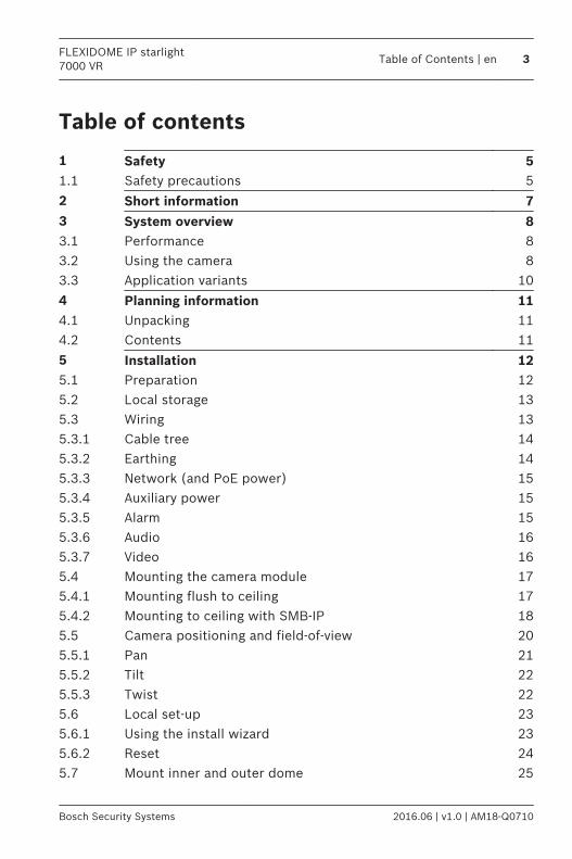
Table of contents
1 Safety 51.1 Safety precautions 5
2 Short information 73 System overview 83.1 Performance 83.2 Using the camera 83.3 Application variants 10
4 Planning information 114.1 Unpacking 114.2 Contents 11
5 Installation 125.1 Preparation 125.2 Local storage 135.3 Wiring 135.3.1 Cable tree 145.3.2 Earthing 145.3.3 Network (and PoE power) 155.3.4 Auxiliary power 155.3.5 Alarm 155.3.6 Audio 165.3.7 Video 165.4 Mounting the camera module 175.4.1 Mounting flush to ceiling 175.4.2 Mounting to ceiling with SMB-IP 185.5 Camera positioning and field-of-view 205.5.1 Pan 215.5.2 Tilt 225.5.3 Twist 225.6 Local set-up 235.6.1 Using the install wizard 235.6.2 Reset 245.7 Mount inner and outer dome 25
FLEXIDOME IP starlight7000 VR
Table of Contents | en 3
Bosch Security Systems 2016.06 | v1.0 | AM18-Q0710
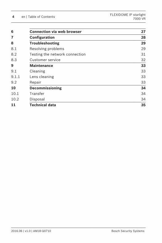
6 Connection via web browser 277 Configuration 288 Troubleshooting 298.1 Resolving problems 298.2 Testing the network connection 318.3 Customer service 32
9 Maintenance 339.1 Cleaning 339.1.1 Lens cleaning 339.2 Repair 33
10 Decommissioning 3410.1 Transfer 3410.2 Disposal 34
11 Technical data 35
4 en | Table of ContentsFLEXIDOME IP starlight
7000 VR
2016.06 | v1.0 | AM18-Q0710 Bosch Security Systems

Safety
!
Caution!
Indicates a hazardous situation which, if not avoided, could
result in minor or moderate injury.
Notice!
Indicates a situation which, if not avoided, could result in
damage to the equipment or environment, or data loss.
Safety precautions
!
Caution!
The Low Voltage power supply unit must comply with EN/UL
60950. The power supply must be a SELV-LPS unit or a SELV -
Class 2 unit (Safety Extra Low Voltage - Limited Power Source).
!
Caution!
Installation should only be performed by qualified service
personnel in accordance with the National Electrical Code
(NEC 800 CEC Section 60) or applicable local codes.
Read, follow, and retain for future reference all of the followingsafety instructions. Follow all warnings before operating thedevice.1. Clean only with a dry cloth. Do not use liquid cleaners or
aerosol cleaners.2. Do not install device near any heat sources such as
radiators, heaters, stoves, or other equipment (includingamplifiers) that produce heat.
3. Never spill liquid of any kind on the device.4. Take precautions to protect the device from power and
lightning surges.
1
1.1
FLEXIDOME IP starlight7000 VR
Safety | en 5
Bosch Security Systems 2016.06 | v1.0 | AM18-Q0710

5. Adjust only those controls specified in the operatinginstructions.
6. Operate the device only from the type of power sourceindicated on the label.
7. Unless qualified, do not attempt to service a damageddevice yourself. Refer all servicing to qualified servicepersonnel.
8. Install in accordance with the manufacturer's instructions inaccordance with applicable local codes.
9. Use only attachments/accessories specified by themanufacturer.
10. Protect all connection cables from possible damage,particularly at connection points.
11. Connect the yellow/green earth wire of the camera to thesystem earth of the installation to ensure correct safety andEMC/RFI protection.
6 en | SafetyFLEXIDOME IP starlight
7000 VR
2016.06 | v1.0 | AM18-Q0710 Bosch Security Systems
Short information
http://www.boschsecurity.com/catalog_overview.htmThis manual has been compiled with great care and theinformation it contains has been thoroughly verified. The textwas correct at the time of printing, however, the content canchange without notice. Bosch Security Systems accepts noliability for damage resulting directly or indirectly from faults,incompleteness or discrepancies between this manual and theproduct described.For more information please contact the nearest Bosch SecuritySystems location or visit www.boschsecurity.comAll hardware and software product names used in this documentare likely to be registered trademarks and must be treatedaccordingly.
2
FLEXIDOME IP starlight7000 VR
Short information | en 7
Bosch Security Systems 2016.06 | v1.0 | AM18-Q0710
System overview
PerformanceThis camera provides clear images 24/7 – even at night or underlow-light conditions.The exceptional starlight sensitivity enables this camera to workwith a minimum of ambient light. The extended dynamic modeprovides detailed images in scenes with challenging lighting.The camera is available in 1080p or 720p resolution versionsand provides up to 60 images per second.The aesthetic vandal-resistant housing makes the camerasuitable for indoor or outdoor installation.
Using the cameraUse a web browser to access the camera features and to viewthe camera streams live. Use the same browser interface toaccess and change the camera configuration parameters andrecording/storage functions (including local alarm recording,and recording to iSCSI-based systems).Refer to the software manual for more information on thebrowser interface.The web browser is the most direct way of using the camera,however, the Bosch download store provides several other freeapplications (listed below) for viewing and controlling thecamera.
Download storeDownload the latest applications and firmware from:http://downloadstore.boschsecurity.com/
3
3.1
3.2
8 en | System overviewFLEXIDOME IP starlight
7000 VR
2016.06 | v1.0 | AM18-Q0710 Bosch Security Systems
Video Security ClientThe Video Security Client is a free, easy-to-use video-surveillanceapplication provided by Bosch for local and remote monitoringof IP cameras and appliances. The software supports up to 16cameras.
Bosch Video ClientThe Bosch Video Client is a free Windows application to view,operate, control, and administer surveillance cameras andinstallations at remote locations. It offers a user-friendlyinterface for easy live viewing of multiple cameras, playback,forensic search and export.
IP HelperThe IP Helper tool is a free PC application that makes it easy todetect Bosch cameras and devices on your network.
Video security appThe Bosch video security mobile app has been developed toenable Anywhere access to HD surveillance images allowing youto view live images from any location. The app is designed togive you complete control of all your cameras, from panning andtilting to zoom and focus functions. It’s like taking your controlroom with you.This app, together with the separately available Boschtranscoder, will allow you to fully utilize our dynamictranscoding features so you can play back images even over low-bandwidth connections.
FLEXIDOME IP starlight7000 VR
System overview | en 9
Bosch Security Systems 2016.06 | v1.0 | AM18-Q0710
Application variantsThe camera has a choice of application variants that set up thecamera for optimum performance in a specific environment.Select the application variant best suited to your installation.The application variant must be selected before any otherchanges are made, as the camera reboots automatically andresets the factory defaults when the application variant ischanged.This camera has the following application variants:– Starlight mode (default) – to continue viewing in color at
very low light levels– Extended Dynamic mode - simultaneously see details in
very bright and very dark objects in the same scene
3.3
10 en | System overviewFLEXIDOME IP starlight
7000 VR
2016.06 | v1.0 | AM18-Q0710 Bosch Security Systems
Planning information
UnpackingThis equipment should be unpacked and handled with care. If anitem appears to have been damaged in shipment, notify theshipper immediately.Verify that all parts are included. If any items are missing, notifyyour Bosch Security Systems Sales or Customer ServiceRepresentative.The original packaging is the safest container in which totransport the unit and can be used if returning the unit forservice.
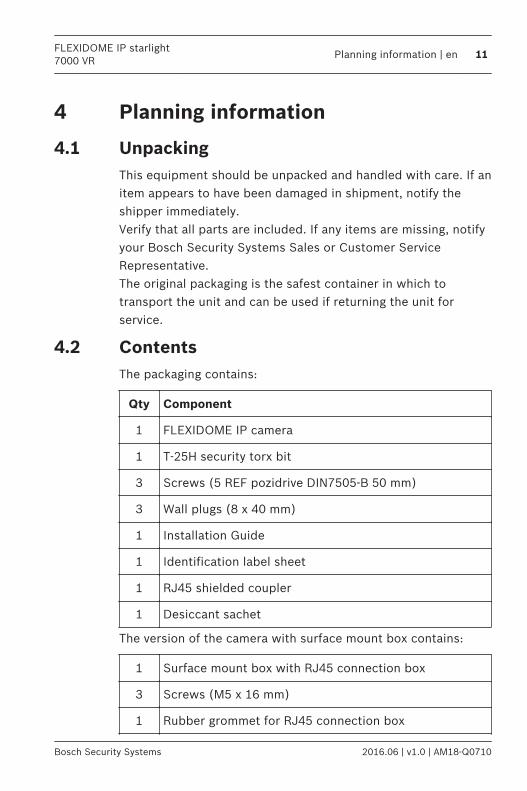
ContentsThe packaging contains:
Qty Component
1 FLEXIDOME IP camera
1 T-25H security torx bit
3 Screws (5 REF pozidrive DIN7505-B 50 mm)
3 Wall plugs (8 x 40 mm)
1 Installation Guide
1 Identification label sheet
1 RJ45 shielded coupler
1 Desiccant sachet
The version of the camera with surface mount box contains:
1 Surface mount box with RJ45 connection box
3 Screws (M5 x 16 mm)
1 Rubber grommet for RJ45 connection box
4
4.1
4.2
FLEXIDOME IP starlight7000 VR
Planning information | en 11
Bosch Security Systems 2016.06 | v1.0 | AM18-Q0710
Installation
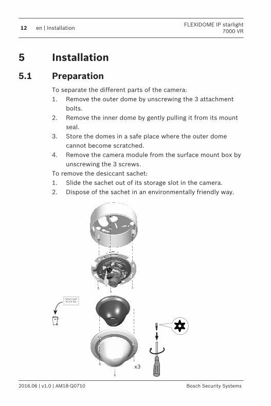
PreparationTo separate the different parts of the camera:1. Remove the outer dome by unscrewing the 3 attachment
bolts.2. Remove the inner dome by gently pulling it from its mount
seal.3. Store the domes in a safe place where the outer dome
cannot become scratched.4. Remove the camera module from the surface mount box by
unscrewing the 3 screws.To remove the desiccant sachet:1. Slide the sachet out of its storage slot in the camera.2. Dispose of the sachet in an environmentally friendly way.
x3
DESICCANT
SILICA GEL
5
5.1
12 en | InstallationFLEXIDOME IP starlight
7000 VR
2016.06 | v1.0 | AM18-Q0710 Bosch Security Systems
Local storage
Notice!
Local storage on memory cards should only be used for alarm
recording. To minimize the risk of losing information, use
multiple, redundant recording systems and a procedure to back
up all digital information.
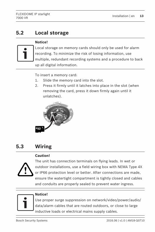
To insert a memory card:1. Slide the memory card into the slot.2. Press it firmly until it latches into place in the slot (when
removing the card, press it down firmly again until itunlatches).
Wiring
!
Caution!
The unit has connection terminals on flying leads. In wet or
outdoor installations, use a field wiring box with NEMA Type 4X
or IP66 protection level or better. After connections are made,
ensure the watertight compartment is tightly closed and cables
and conduits are properly sealed to prevent water ingress.
Notice!
Use proper surge suppression on network/video/power/audio/
data/alarm cables that are routed outdoors, or close to large
inductive loads or electrical mains supply cables.
5.2
5.3
FLEXIDOME IP starlight7000 VR
Installation | en 13
Bosch Security Systems 2016.06 | v1.0 | AM18-Q0710

Cable treeUse the following table to identify the wires in the cable tree:
Wire color AWC Signal
Red 26 +12 VDC
Brown 26 -12 VDC
Yellow /Green
24 Earth
Black /Brown
28 Alarm Out A
White /Orange
28 Alarm Out B
White /Violet
28 Ground (Alarm In)
Orange /Violet
28 Alarm In 1
Violet 28 Alarm In 2
White 28 Audio In
(Shield) 28 Ground (Audio)
Black 28 Audio Out
BNCconnector
CVBS analog
Earthing
!
Caution!
This device must be connected to earth (ground).
Safety (power) ground is indicated by the symbol.
5.3.1
5.3.2
14 en | InstallationFLEXIDOME IP starlight
7000 VR
2016.06 | v1.0 | AM18-Q0710 Bosch Security Systems
Connect the yellow/green wire of the camera to the systemearth of the installation to ensure correct safety and EMC/RFIprotection.
Network (and PoE power)Connect the camera to a 10/100 Base-T network:– Use STP Category 5e cable with RJ45 connectors (the
camera network socket is Auto MDIX compliant).– Power is supplied to the camera via the Ethernet cable
compliant with the Power-over-Ethernet standard.
Notice!
Use only PoE approved devices.
Power-over-Ethernet can be connected at the same time as a12 VDC power supply. If auxiliary power (12 VDC) and PoE isapplied simultaneously, the camera selects PoE and shuts offthe auxiliary input.
Auxiliary powerConnect a SELV-LPS or a SELV Class 2 power supply with arated supply voltage of 12 VDC as follows:– Cut back 7 mm (0.28 in) of insulation.– Connect the power wires (red+ , brown-) to the external
power supply.
!
Caution!
Use only a +12 VDC power supply as an auxiliary power source.
The auxiliary power supply unit must be isolated from earth.
AlarmUse the stranded and solid wires with maximum diameter AWG22-28; only cut back 5 mm (0.2 in) of insulation.
5.3.3
5.3.4
5.3.5
FLEXIDOME IP starlight7000 VR
Installation | en 15
Bosch Security Systems 2016.06 | v1.0 | AM18-Q0710
Alarm out:Use the alarm output for switching external devices such aslamps or sirens.The alarm output switching capability has max. voltage 30 VACor +40 VDC; max. 0.5 A continuous, 10 VA.
Alarm in:Use the alarm input to connect external alarm devices such asdoor contacts or sensors:– TTL logic, +5 V nominal, +40 VDC max, DC coupled with
50 kOhm pull-up to +3.3 V.– Configurable as active low or active high.Use a zero potential make-contact or switch as the actuator(with a bounce-free contact system).
AudioConnect audio devices to the audio input and audio outputconnectors.The unit has full-duplex mono audio for two-way communicationbetween a speaker or door intercom system. The audio inputsignal is transmitted in sync. with the video signal.
Audio input:Line input level (not suitable for direct microphone signal);impedance 18 kOhm typical; 1 Vrms maximum input voltage.
Audio output:Line output level (not suitable for direct speaker connection);impedance 1.5 kOhm minimum; 0.85 Vrms maximum outputvoltage.Use shielded audio connection cable with advised maximumcable lengths for audio line input and output levels.
VideoUse the composite video connector (CVBS) on the camera toconnect an analog monitor for setting up the camera or as apermanent analog output for viewing or recording:
5.3.6
5.3.7
16 en | InstallationFLEXIDOME IP starlight
7000 VR
2016.06 | v1.0 | AM18-Q0710 Bosch Security Systems
– To connect a monitor for set-up, use the optional 3 m cable(NBN-MCSMB-30M) to connect directly to the CVBSconnector of a monitor.
– For a permanent analog output, use the optional 0.3 mcable (NBN-MCSMB-03M) to connect to a high quality coaxcable.
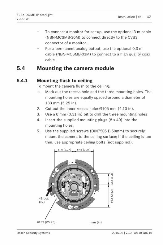
Mounting the camera module
Mounting flush to ceilingTo mount the camera flush to the ceiling:1. Mark out the recess hole and the three mounting holes. The
mounting holes are equally spaced around a diameter of133 mm (5.25 in).
2. Cut out the inner recess hole: Ø105 mm (4.13 in).3. Use a 8 mm (0.31 in) bit to drill the three mounting holes4. Insert the supplied mounting plugs (8 x 40) into the
mounting holes.5. Use the supplied screws (DIN7505-B 50mm) to securely
mount the camera to the ceiling surface; if the ceiling is toothin, use appropriate ceiling bolts (not supplied).
57.6 (2.27) 57.6 (2.27)
33.3
(1.3
1)
66.5
(2.6
2)
Ø133 (Ø5.25) mm (in)
4S box
(x2)
5.4
5.4.1
FLEXIDOME IP starlight7000 VR
Installation | en 17
Bosch Security Systems 2016.06 | v1.0 | AM18-Q0710

Ø8 m
m
x3
105 (4.13)
STP Cat5e
RJ45
Ethernet
(PoE)
Earth+12 VDC
PowerAlarm
Audio
BNC
female
75 Ohm
CVBS
Note:If using a recessed 4s mounting box, attach the camera to thebox using two screws and washers (M4 x 14).
Mounting to ceiling with SMB-IPTo mount the camera using a Surface Mount Box and cableconduit:1. Use the SMB to mark out the cable hole in the ceiling and
to mark the three mounting holes. The mounting holes areequally spaced around a diameter of 133 mm (5.25 in).
2. Cut out the cable hole in the ceiling, and use a 8 mm(0.31 in) bit to drill the three mounting holes.
3. Insert the supplied mounting plugs (8 x 40) into themounting holes.
5.4.2
18 en | InstallationFLEXIDOME IP starlight
7000 VR
2016.06 | v1.0 | AM18-Q0710 Bosch Security Systems
4. Use the supplied screws (pozidrive DIN7505-B 50mm) tosecurely attach the SMB to the surface.
5. Feed the Ethernet RJ45 cable from source through theceiling into the SMB
6. Remove the cover from the SMB cable conduit and slideout the rubber seals at either end.
7. Thread the Ethernet cables from the camera and sourcethrough the seals (they can be pulled open to fit thecables). If required, use the larger bore seal (supplied inparts package) to fit thicker cables.
8. Slot the seals (with cables) into either end of the conduit.9. Connect the Ethernet cables inside the conduit using the
supplied RJ45 shielded connector.10. Close the cover on the conduit and position the conduit
inside the SMB.11. Feed the other camera cabling through the cable hole in the
SMB.12. If IP66 water ingress protection is required, connect the
camera cabling to the source cabling inside an IP66approved box.
13. Mount the camera to the SMB using the 3 supplied screws(M5x16mm torx).
FLEXIDOME IP starlight7000 VR
Installation | en 19
Bosch Security Systems 2016.06 | v1.0 | AM18-Q0710
IP66
STP Cat5e
RJ45
Ethernet
(PoE)
Earth
+12 VDC
Power
Alarm
Audio
CVBS
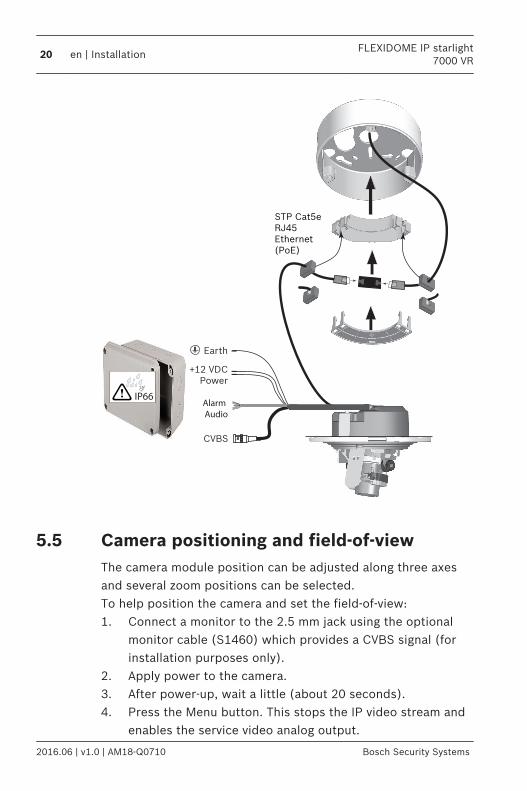
Camera positioning and field-of-viewThe camera module position can be adjusted along three axesand several zoom positions can be selected.To help position the camera and set the field-of-view:1. Connect a monitor to the 2.5 mm jack using the optional
monitor cable (S1460) which provides a CVBS signal (forinstallation purposes only).
2. Apply power to the camera.3. After power-up, wait a little (about 20 seconds).4. Press the Menu button. This stops the IP video stream and
enables the service video analog output.
5.5
20 en | InstallationFLEXIDOME IP starlight
7000 VR
2016.06 | v1.0 | AM18-Q0710 Bosch Security Systems
Menu
Reset
S1460
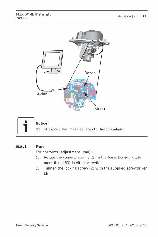
Notice!
Do not expose the image sensors to direct sunlight.
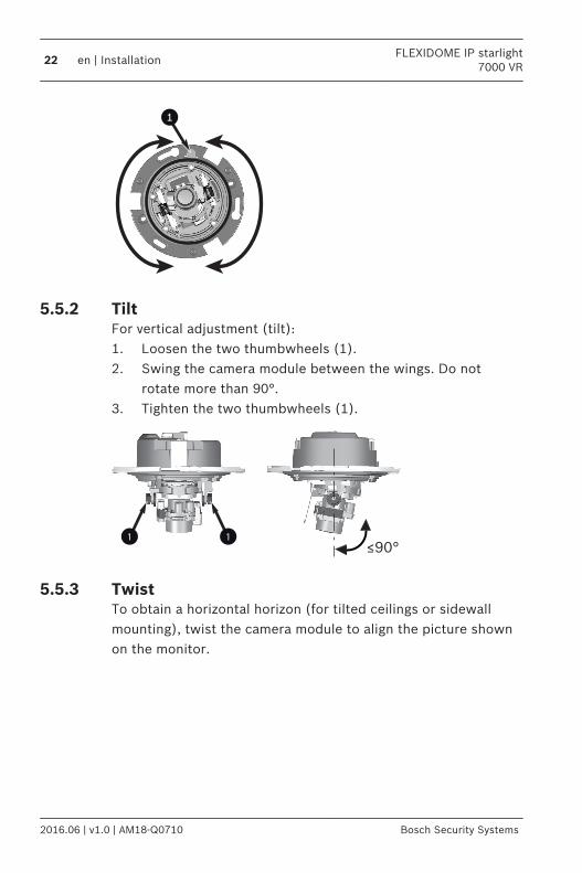
PanFor horizontal adjustment (pan):1. Rotate the camera module (1) in the base. Do not rotate
more than 180° in either direction.2. Tighten the locking screw (2) with the supplied screwdriver
bit.
5.5.1
FLEXIDOME IP starlight7000 VR
Installation | en 21
Bosch Security Systems 2016.06 | v1.0 | AM18-Q0710
1
TiltFor vertical adjustment (tilt):1. Loosen the two thumbwheels (1).2. Swing the camera module between the wings. Do not
rotate more than 90°.3. Tighten the two thumbwheels (1).
≤90°1 1
TwistTo obtain a horizontal horizon (for tilted ceilings or sidewallmounting), twist the camera module to align the picture shownon the monitor.
5.5.2
5.5.3
22 en | InstallationFLEXIDOME IP starlight
7000 VR
2016.06 | v1.0 | AM18-Q0710 Bosch Security Systems
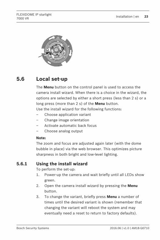
Local set-upThe Menu button on the control panel is used to access thecamera install wizard. When there is a choice in the wizard, theoptions are selected by either a short press (less than 2 s) or along press (more than 2 s) of the Menu button.Use the install wizard for the following functions:– Choose application variant– Change image orientation– Activate automatic back focus– Choose analog output
Note:The zoom and focus are adjusted again later (with the domebubble in place) via the web browser. This optimizes picturesharpness in both bright and low-level lighting.
Using the install wizardTo perform the set-up:1. Power-up the camera and wait briefly until all LEDs show
green.2. Open the camera install wizard by pressing the Menu
button.3. To change the variant, briefly press Menu a number of
times until the desired variant is shown (remember thatchanging the variant will reboot the system and mayeventually need a reset to return to factory defaults).
5.6
5.6.1
FLEXIDOME IP starlight7000 VR
Installation | en 23
Bosch Security Systems 2016.06 | v1.0 | AM18-Q0710
4. To confirm the selected variant, press Menu for a longertime.
5. To rotate the image 180°, press and hold Menu until theimage flips.
6. Briefly press the Menu button to set the start position forthe automatic motorized focus adjustment.– You will hear the motorized automatic back focus
process running.– The progress is shown on the monitor.
7. Briefly press the Menu button again and again to scrollthrough the preset zoom positions.– The selection loops back to the beginning when you
reach the last one.8. When you reach the desired zoom position, use a long
press of the Menu button to set the zoom position and tore-focus.
9. If the camera is not in focus, press Menu for a longer timeto re-run the auto focus.
10. If the camera is correctly focused, briefly press the Menubutton to access the video analog output format screen.
11. Briefly press Menu to change the video analog outputformat as required.
12. When the correct format is shown, press Menu for a longerperiod to exit the wizard.
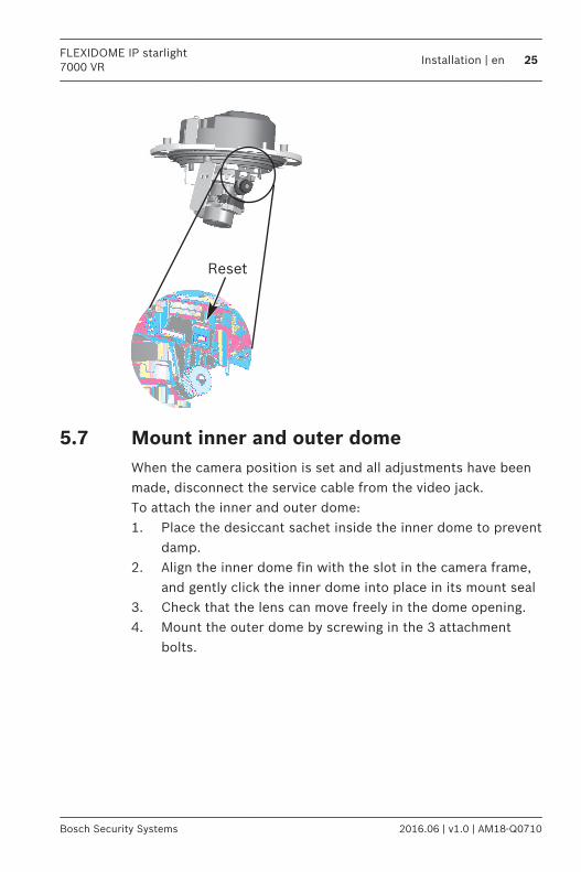
ResetUse the factory reset button to restore the unit to its originalsettings. Any changes to the settings are overwritten by thefactory defaults. A reset may be necessary, for example, if theunit has invalid settings that prevent it from functioning asdesired.
5.6.2
24 en | InstallationFLEXIDOME IP starlight
7000 VR
2016.06 | v1.0 | AM18-Q0710 Bosch Security Systems
Reset
Mount inner and outer domeWhen the camera position is set and all adjustments have beenmade, disconnect the service cable from the video jack.To attach the inner and outer dome:1. Place the desiccant sachet inside the inner dome to prevent
damp.2. Align the inner dome fin with the slot in the camera frame,
and gently click the inner dome into place in its mount seal3. Check that the lens can move freely in the dome opening.4. Mount the outer dome by screwing in the 3 attachment
bolts.
5.7
FLEXIDOME IP starlight7000 VR
Installation | en 25
Bosch Security Systems 2016.06 | v1.0 | AM18-Q0710
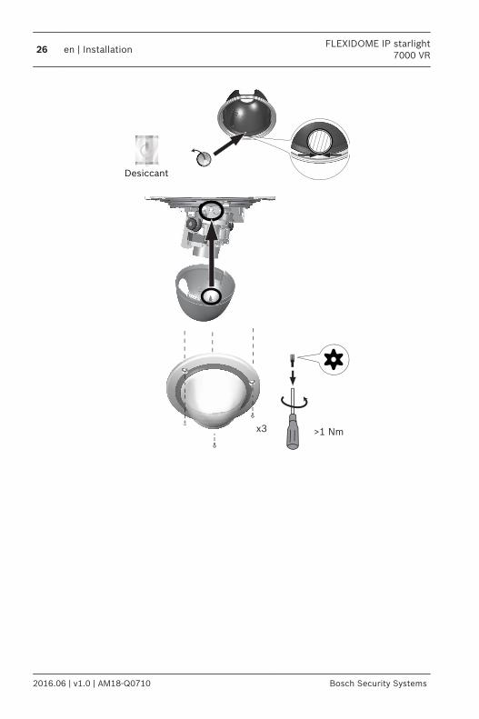
>1 Nmx3
DesiccantDesiccant
26 en | InstallationFLEXIDOME IP starlight
7000 VR
2016.06 | v1.0 | AM18-Q0710 Bosch Security Systems
Connection via web browserThe unit must have a valid IP address and a compatible subnetmask to operate on your network. By default, DHCP is pre-set atthe factory to On and so your DHCP server assigns an IPaddress. With no DHCP server the default address is192.168.0.1To view the camera in your web browser:1. Start the Web browser.2. Enter the IP address of the unit as the URL.3. During initial installation, confirm any security questions
that appear.Note:To see live images in your browser it might be necessary todownload and install the MPEG-ActiveX from the Boschdownload store.
Protected NetworkIf a RADIUS server is used for network access control (802.1xauthentication), the unit must be configured first. To configurethe unit, connect it directly to a computer using a network cableand configure the two parameters, Identity and Password. Onlyafter these have been configured can communication with theunit via the network occur.
IP Helper toolAlternatively, use the IP Helper tool to detect Bosch devices onthe network:1. Access the Bosch download store (http://
downloadstore.boschsecurity.com/).2. Download and install IP Helper.3. Choose your specific camera from the list of cameras
shown in the table on the left of the screen4. Click Open in browser to view the camera interface.
6
FLEXIDOME IP starlight7000 VR
Connection via web browser | en 27
Bosch Security Systems 2016.06 | v1.0 | AM18-Q0710
ConfigurationThe camera normally provides an optimal picture without theneed for further adjustments. However, you can use a webbrowser via the network to access a menu to change camerasettings such as user modes, passwords, picture settings andnetwork settings.Configuration options using the menu system on the cameraitself are limited to basic setup via the Wizard.1. Open the camera in the web browser.2. Click Configuration in the title bar.3. Select Camera >> Installer Menu from the side bar.4. Select the application variant before any other changes are
made, as the camera reboots automatically and resets thefactory defaults when the application variant is changed.
If required, configure the parameters in other menus to suit yourworking environment (for example, ID, passwords, date andtime). Refer to the operation manuals of the software for moreinformation.
7
28 en | ConfigurationFLEXIDOME IP starlight
7000 VR
2016.06 | v1.0 | AM18-Q0710 Bosch Security Systems
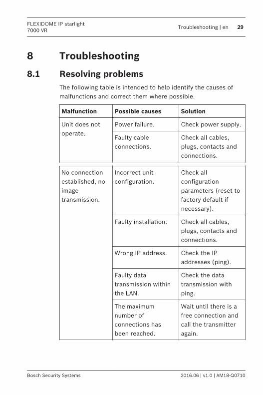
Troubleshooting
Resolving problemsThe following table is intended to help identify the causes ofmalfunctions and correct them where possible.
Malfunction Possible causes Solution
Unit does notoperate.
Power failure. Check power supply.
Faulty cableconnections.
Check all cables,plugs, contacts andconnections.
No connectionestablished, noimagetransmission.
Incorrect unitconfiguration.
Check allconfigurationparameters (reset tofactory default ifnecessary).
Faulty installation. Check all cables,plugs, contacts andconnections.
Wrong IP address. Check the IPaddresses (ping).
Faulty datatransmission withinthe LAN.
Check the datatransmission withping.
The maximumnumber ofconnections hasbeen reached.
Wait until there is afree connection andcall the transmitteragain.
8
8.1
FLEXIDOME IP starlight7000 VR
Troubleshooting | en 29
Bosch Security Systems 2016.06 | v1.0 | AM18-Q0710
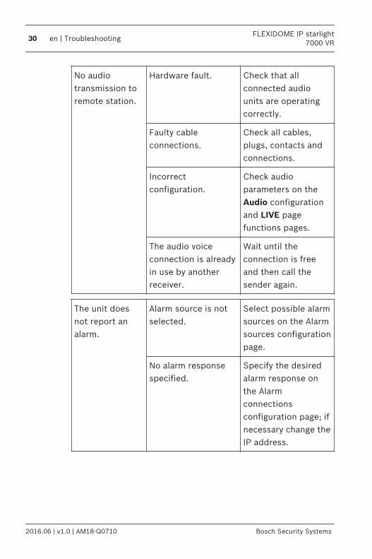
No audiotransmission toremote station.
Hardware fault. Check that allconnected audiounits are operatingcorrectly.
Faulty cableconnections.
Check all cables,plugs, contacts andconnections.
Incorrectconfiguration.
Check audioparameters on theAudio configurationand LIVE pagefunctions pages.
The audio voiceconnection is alreadyin use by anotherreceiver.
Wait until theconnection is freeand then call thesender again.
The unit doesnot report analarm.
Alarm source is notselected.
Select possible alarmsources on the Alarmsources configurationpage.
No alarm responsespecified.
Specify the desiredalarm response onthe Alarmconnectionsconfiguration page; ifnecessary change theIP address.
30 en | TroubleshootingFLEXIDOME IP starlight
7000 VR
2016.06 | v1.0 | AM18-Q0710 Bosch Security Systems
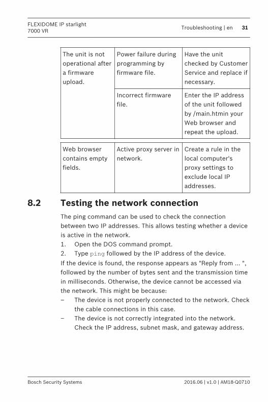
The unit is notoperational aftera firmwareupload.
Power failure duringprogramming byfirmware file.
Have the unitchecked by CustomerService and replace ifnecessary.
Incorrect firmwarefile.
Enter the IP addressof the unit followedby /main.htmin yourWeb browser andrepeat the upload.
Web browsercontains emptyfields.
Active proxy server innetwork.
Create a rule in thelocal computer'sproxy settings toexclude local IPaddresses.
Testing the network connectionThe ping command can be used to check the connectionbetween two IP addresses. This allows testing whether a deviceis active in the network.1. Open the DOS command prompt.2. Type ping followed by the IP address of the device.
If the device is found, the response appears as "Reply from ... ",followed by the number of bytes sent and the transmission timein milliseconds. Otherwise, the device cannot be accessed viathe network. This might be because:– The device is not properly connected to the network. Check
the cable connections in this case.– The device is not correctly integrated into the network.
Check the IP address, subnet mask, and gateway address.
8.2
FLEXIDOME IP starlight7000 VR
Troubleshooting | en 31
Bosch Security Systems 2016.06 | v1.0 | AM18-Q0710
Customer serviceIf a fault cannot be resolved, please contact your supplier orsystem integrator, or go directly to Bosch Security SystemsCustomer Service.The version numbers of the internal firmware can be viewed ona service page. Please note this information before contactingCustomer Service.1. In the address bar of your browser, after the unit IP
address, enter: /versionfor example: 192.168.0.80/version
2. Write down the information or print out the page.
8.3
32 en | TroubleshootingFLEXIDOME IP starlight
7000 VR
2016.06 | v1.0 | AM18-Q0710 Bosch Security Systems
Maintenance
CleaningIt is generally sufficient to use a dry cloth for cleaning, but amoist lint-free cloth or leather shammy may also be used.Do not use liquid cleaners or aerosol cleaners.
Lens cleaningIt is important to keep the lens clean to ensure optimumperformance. Dust, grease, or fingerprints should be removedfrom the lens surface. When cleaning the lens, take extra carenot to damage the special coating used to reduce lightreflections.– Remove dust with a blower-brush or grease-free soft brush.– Wipe water drops off the lens with a clean soft lint-free
cloth and dry the lens surface.– Use special lens cleaning paper or cloth treated with lens
cleaning fluid to gently wipe off any remaining dirt (wipespirally from the lens center towards the edge).
Repair
Notice!
Never open the casing of the unit
The unit does not contain any user-serviceable parts. Refer allrepairs to suitable qualified specialists.
9
9.1
9.1.1
9.2
FLEXIDOME IP starlight7000 VR
Maintenance | en 33
Bosch Security Systems 2016.06 | v1.0 | AM18-Q0710
Decommissioning
TransferThe unit should only be passed on together with this installationguide.
Disposal
Disposal - Your Bosch product was developed andmanufactured with high-quality material and components thatcan be recycled and reused. This symbol means thatelectronic and electrical appliances, which have reached theend of their working life, must be collected and disposed ofseparately from household waste material. Separate collectingsystems are usually in place for disused electronic andelectrical products. Please dispose of these units at anenvironmentally compatible recycling facility, per EuropeanDirective 2012/19/EU.
10
10.1
10.2
34 en | DecommissioningFLEXIDOME IP starlight
7000 VR
2016.06 | v1.0 | AM18-Q0710 Bosch Security Systems
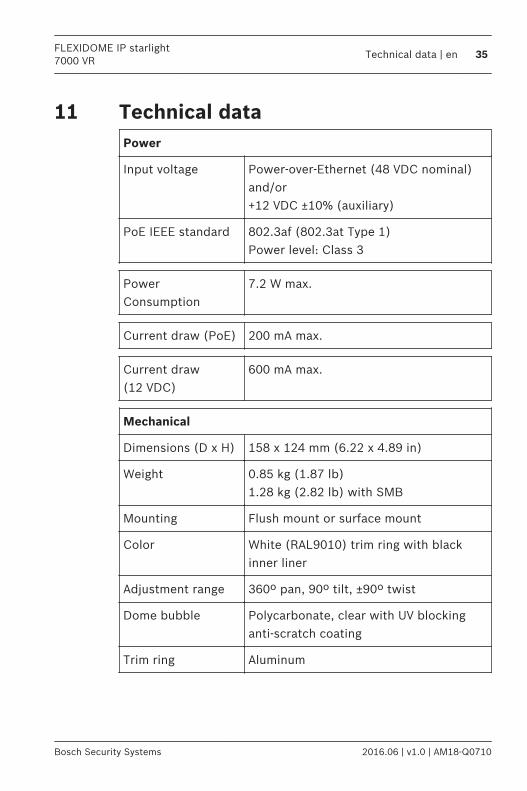
Technical dataPower
Input voltage Power-over-Ethernet (48 VDC nominal)and/or +12 VDC ±10% (auxiliary)
PoE IEEE standard 802.3af (802.3at Type 1)Power level: Class 3
PowerConsumption
7.2 W max.
Current draw (PoE) 200 mA max.
Current draw(12 VDC)
600 mA max.
Mechanical
Dimensions (D x H) 158 x 124 mm (6.22 x 4.89 in)
Weight 0.85 kg (1.87 lb)1.28 kg (2.82 lb) with SMB
Mounting Flush mount or surface mount
Color White (RAL9010) trim ring with blackinner liner
Adjustment range 360º pan, 90º tilt, ±90º twist
Dome bubble Polycarbonate, clear with UV blockinganti-scratch coating
Trim ring Aluminum
11
FLEXIDOME IP starlight7000 VR
Technical data | en 35
Bosch Security Systems 2016.06 | v1.0 | AM18-Q0710

Environmental
Operatingtemperature
-30 ºC to +50 ºC (-22 ºF to +122 ºF) forcontinuous operation;-34 ºC to +74 ºC (-30 ºF to +165 ºF)according to NEMA TS 2-2003 (R2008),para 2.1.5.1 using fig. 2.1 test profile
Cold starttemperature
-20 ºC (-4 ºF)
Storagetemperature
-50 ºC to +70 ºC (-58 ºF to +158 ºF)
Operating humidity 5% to 93% relative humidity
Storage humidity Up to 98% relative humidity
Impact protection IK10
Water/dustprotection
IP 66 and NEMA Type 4X (withappropriate installation standards)
Dimensions
Ø158 (6.22)
Ø95 (3.7)
mm (in)
39
(1
.54)
85
(3.3
5)
36 en | Technical dataFLEXIDOME IP starlight
7000 VR
2016.06 | v1.0 | AM18-Q0710 Bosch Security Systems
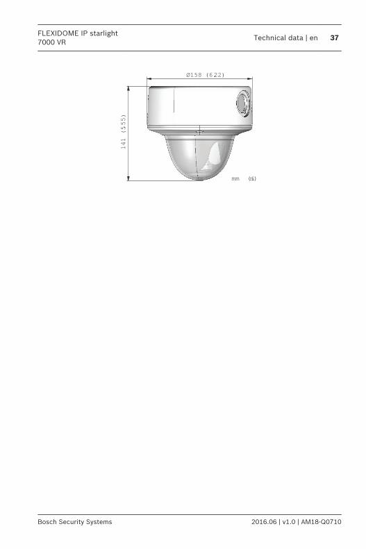
141 (5.55)
Ø158 (6.22)
mm (in)
FLEXIDOME IP starlight7000 VR
Technical data | en 37
Bosch Security Systems 2016.06 | v1.0 | AM18-Q0710


Bosch Security Systems B.V.Torenallee 495617 BA EindhovenNetherlandswww.boschsecurity.com© Bosch Security Systems B.V., 2016