7.0 Electrical Power Lines - State Electrical Power Lines Electrical service requirements for the...
28
7-1 July 6, 2009 7.0 Electrical Power Lines Electrical service requirements for the Project include utilizing existing service lines and newly-constructed electrical transmission and distribution power lines to the tank farm, pump stations, and delivery facilities. Because local electrical power providers, not Keystone, will be constructing and operating the electrical power lines, the electrical power providers will be responsible for obtaining any necessary approvals or authorizations from federal, state, and local governments. While the permitting process for the electrical facilities is an independent process from the pipeline ROW approval process, the construction and operation of these power lines are considered connected actions under NEPA and, therefore, are evaluated within this Environmental Report for the Project. A summary of power line routing discussions is included in Appendix Z. 7.1 Electrical Power Line Requirements New electrical transmission power lines (i.e., power line with voltage of 69 kV or greater) will be constructed to service pump stations and a tank farm along the Project route. Other electric power requirements (e.g., valve sites) will be supplied from distribution service drops from adjacent distribution power lines (i.e., power line with voltage below 69 kV). Each of these distribution service drops will require the installation of approximately one or two poles and a transformer. The length of these distribution service drops typically will be less than 200 feet. Power providers will restore the work area as required upon completion of the new service drop in accordance with local permits. Figure 7.1-1 illustrates a typical power line single pole structure, with size and height depending on the electrical load the line will carry. Generally, power poles will be 50 to 65 feet high. Table 7.1-1 details the proposed lengths for the new electrical power lines associated with the Project pump stations and tank farm. Preliminary routing has been identified in consultation with utility companies for each power line. Where feasible, the entire length of each of these preliminary power line routes has been placed along existing county roads, section lines, or field edges to minimize interference with adjacent agricultural lands. The preliminary power line proposed alternative routes that link existing power lines to each pump station are illustrated on the Power Line Route Sheets (Appendix B). These routes are subject to change as the pump station supply requirements are further reviewed with the power providers. Table 7.1-1 Estimated Lengths Requirements for the Proposed Electrical Power Lines Power Line to Pump Station No. County Utility Supply (kV) Approximate Length (miles) Typical Pole/Tower Spacing (feet) Structure Design Steele City Segment Montana PS-09 Phillips 115 62.4 500-600 Single pole PS-10A-1 Valley/McCone 115 51.0 500-600 Single pole PS-11 McCone/Valley 115 12.0 500-600 Single pole PS-12 McCone 115 3.3 500-600 Single pole PS-13A-2 Prairie 115 13.5 500-600 Single pole PS-14A-1 Fallon 115 5.2 500-600 Single pole South Dakota PS-15A-2 Harding 115 23.0 500-600 Single pole PS-16 Harding/Butte 115 45.7 500-600 Single pole PS-17A-2 Meade 115 11.0 500-600 Single pole
-
Upload
trinhtuong -
Category
Documents
-
view
220 -
download
5
Transcript of 7.0 Electrical Power Lines - State Electrical Power Lines Electrical service requirements for the...

7-1 July 6, 2009
7.0 Electrical Power Lines
Electrical service requirements for the Project include utilizing existing service lines and newly-constructed electrical transmission and distribution power lines to the tank farm, pump stations, and delivery facilities. Because local electrical power providers, not Keystone, will be constructing and operating the electrical power lines, the electrical power providers will be responsible for obtaining any necessary approvals or authorizations from federal, state, and local governments. While the permitting process for the electrical facilities is an independent process from the pipeline ROW approval process, the construction and operation of these power lines are considered connected actions under NEPA and, therefore, are evaluated within this Environmental Report for the Project. A summary of power line routing discussions is included in Appendix Z.
7.1 Electrical Power Line Requirements New electrical transmission power lines (i.e., power line with voltage of 69 kV or greater) will be constructed to service pump stations and a tank farm along the Project route. Other electric power requirements (e.g., valve sites) will be supplied from distribution service drops from adjacent distribution power lines (i.e., power line with voltage below 69 kV). Each of these distribution service drops will require the installation of approximately one or two poles and a transformer. The length of these distribution service drops typically will be less than 200 feet. Power providers will restore the work area as required upon completion of the new service drop in accordance with local permits. Figure 7.1-1 illustrates a typical power line single pole structure, with size and height depending on the electrical load the line will carry. Generally, power poles will be 50 to 65 feet high.
Table 7.1-1 details the proposed lengths for the new electrical power lines associated with the Project pump stations and tank farm. Preliminary routing has been identified in consultation with utility companies for each power line. Where feasible, the entire length of each of these preliminary power line routes has been placed along existing county roads, section lines, or field edges to minimize interference with adjacent agricultural lands. The preliminary power line proposed alternative routes that link existing power lines to each pump station are illustrated on the Power Line Route Sheets (Appendix B). These routes are subject to change as the pump station supply requirements are further reviewed with the power providers.
Table 7.1-1 Estimated Lengths Requirements for the Proposed Electrical Power Lines
Power Line to Pump Station No. County
Utility Supply
(kV)
Approximate Length (miles)
Typical Pole/Tower
Spacing (feet) Structure Design
Steele City Segment Montana PS-09 Phillips 115 62.4 500-600 Single pole PS-10A-1 Valley/McCone 115 51.0 500-600 Single pole PS-11 McCone/Valley 115 12.0 500-600 Single pole PS-12 McCone 115 3.3 500-600 Single pole PS-13A-2 Prairie 115 13.5 500-600 Single pole PS-14A-1 Fallon 115 5.2 500-600 Single pole South Dakota PS-15A-2 Harding 115 23.0 500-600 Single pole PS-16 Harding/Butte 115 45.7 500-600 Single pole PS-17A-2 Meade 115 11.0 500-600 Single pole

7-2 July 6, 2009
Table 7.1-1 Estimated Lengths Requirements for the Proposed Electrical Power Lines
Power Line to Pump Station No. County
Utility Supply
(kV)
Approximate Length (miles)
Typical Pole/Tower
Spacing (feet) Structure Design
PS-18 Haakon 115 25.9 500-600 Single pole PS-19A-3 Jones/Haakon 115 20.2 500-600 Single pole PS-20A-2 Tripp 115 15.9 500-600 Single pole PS-21A-1 Tripp/Gregory 115 20.1 500-600 Single pole Nebraska PS-22 Holt 115 7.4 500-600 Single pole PS-23 Wheeler/Valley/
Greeley 115 23.0 500-600 Single pole
PS-24A-1 Merrick/Hamilton 115 10.1 500-600 Single pole PS-25A-1 Filmore/York 69 14.3 300-400 Single pole PS-26/ Steele City Tank Farm1
Jefferson 115 13.3 500-600 Single pole
Cushing Extension Kansas PS-27A-1 Clay 115 10.2 500-600 Single pole PS-29A-2 Butler 115 11.2 500-600 Single pole Gulf Coast Segment Oklahoma PS-32A-1 Payne 138 6.9 600-700 Single pole PS-33A-4 Seminole 138 0.6 600-700 Single pole PS-34A-1 Coal 138 5.3 600-700 Single pole PS-35A-1 Bryan 138 4.1 600-700 Single pole Texas PS-36A-3 Delta 138 7.3 600-700 H-frame PS-37A-2 Wood 138 0.1 600-700 Single pole PS-38A-3 Smith 138 0.2 600-700 Single pole PS-39A-1 Cherokee 138 5.2 600-700 Single pole PS-40A-4 Polk 138 0.3 600-700 Single pole PS-41A-1 Liberty 240 0.4 700-900 H-frame 1 The power line to PS-26 also will supply power to the Steele City tank farm.
Note: Table 7.1-1 does not include power lines constructed to Pump Stations 28 and 31 along the Keystone Cushing Extension, which are being permitted and will be constructed as a portion of the Keystone Cushing Extension.

7-3 July 6, 2009
Figure 7.1-1 Typical Utility Transmission Structure

7-4 July 6, 2009
7.1.1 WAPA-Required Infrastructure The Western Area Power Administration (WAPA) has determined that they need to build an approximately 65-mile-long, 230 kV power line to strengthen the local power grid. Details will be provided once they have been received.
7.2 Electrical Power Line Construction The construction phase for each electrical power line will consist of ROW acquisition, ROW clearing, construction, and site restoration and cleanup. The following is a brief summary of the typical steps associated with power line construction. Actual power line construction procedures will be developed by each power provider to address site specific conditions.
• ROW easements. The electric power provider will obtain any necessary easements.
• ROW clearing. Limited clearing will be required along existing roads in native and improved grasslands and croplands. Some trees may require removal to provide adequate clearance between the conductors and underlying vegetation. Trimming to avoid tree removal may be employed in some locations.
• Power line construction. The structures will be delivered on flatbed trucks. A mobile crane or picker truck may be needed to install the poles. Holes will be excavated for structure placement, typically with radial arm diggers. The wooden or steel poles will be directly embedded into the ground and anchors may be required at angles and dead ends. Pulling or reeling areas will be needed for installation of the conductor wires. Conductors (wires) will be attached to the structure using porcelain or fiberglass insulators.
• Restoration. After the power line structures are in place and the conductors are strung between the structures, the disturbed areas will be restored. The soil in the disturbed areas will be reshaped and contoured to its original condition. Reseeding will follow landowner requirements. All litter and other remaining materials will be removed from the construction areas and properly disposed.
7.3 Affected Environment and Environmental Consequences This section addresses the natural and human resources potentially affected by the construction, operation, and maintenance of the proposed electrical transmission and distribution power lines associated with the Project. Impacts associated with the electrical distribution line service drops are expected to be minimal and comparable to those associated with supplying electricity to the average home or farm.
The proposed power line routes were evaluated for potential environmental impacts through aerial interpretation of the preliminary proposed routes and by field survey wherever practicable. This investigation included land ownership, land use, vegetation cover, wetland and waterbody crossings, cultural resource impacts, and residential structure analyses. Impacts to these resources are based on their location in relation to the proposed surface disturbance areas. The areas of disturbance are estimated based on the extent of disturbance for construction and operation activities. Since exact power line design specifications have yet to have been provided (including precise structure locations), acreage calculations are based on the percentage of each resource within each power line construction ROW. Construction-related impacts are considered temporary impacts; operation-related impacts are considered permanent impacts. The subsequent impact analysis is based on the following assumptions.
Temporary disturbance impact assumptions include:
• Structure placement pads:
− 69-kV: 60-foot radius (based on maximum structure height of 40-60 feet) every 350 feet (based on average structure span range of 300-400 feet)

7-5 July 6, 2009
− 115-kV: 70-foot radius (based on maximum structure height of 50-70 feet) every 550 feet (based on average structure span range of 500-600 feet)
− 138-kV: 80-foot radius (based on maximum structure height of 60-80 feet) every 650 feet (based on average structure span range of 600-700 feet)
− H-frame power lines of any voltage: 90-foot radius (based on maximum structure height of 70-90 feet) every 800 feet (based on average structure span range of 700-900 feet)
• Construction access roads:
− 20-feet-wide within the ROW width for all power lines
• Pulling and tensioning areas:
− 1 acre per change in direction
• Turnaround areas:
− 30-foot radius at each structure
• Staging areas:
− 1 acre every 25 miles
Permanent disturbance impact assumptions include:
• All land use and vegetation cover types within the construction ROW (with the exception of the power pole structure locations and operational access roads) will be reclaimed pursuant to each power providers’ requirements. However, each power provider will maintain a ROW free of woody vegetation where identified as a “forested” land use and vegetation cover type. ROW widths in only forested land use and vegetation cover types are calculated using:
− 69-kV, 115-kV, and 138-kV: 80 feet (based on a maximum of 60-80 foot range)
− All H-frame power lines of any voltage: 150 feet (based on a maximum ROW range of 100-150-feet)
• Power pole structure:
− 69-kV: 12 square feet every 350 feet (based on an average structure span range of 300-400 feet)
− 115-kV: 12 square feet every 550 feet (based on an average structure span range of 500-600 feet)
− 138-KV power lines: 12 square feet every 650 feet (based on an average structure span range of 600-700 feet)
− H-frame power lines of any voltage: 24 square feet every 800 feet (based on an average structure span range of 700-900 feet)
• Operational access roads to each structure:
− 20-feet-wide within the ROW width for all power lines
Additional impact assumptions include:
• Temporary impacts associated with turnaround areas are not mutually exclusive and have been included entirely within the structure placement pad footprint. Construction access roads, structure placement pads, staging areas, and pulling and tensioning areas are mutually exclusive.
• Impacts associated with permanent access roads for use during operation are not included in this analysis due to the lack of detailed power line specifications including number and location of these roads. Actual impacts may increase as a result.

7-6 July 6, 2009
• Impact calculations are divided proportionally to each land use and vegetation cover type including open water found along each route. Actual impacts may be decreased upon further power line design by each power provider in an effort to span sensitive habitats, wetlands, and waterbody features.
• Woody vegetation and trees within and adjacent to the ROW may be cleared if deemed a hazard to power line operation. Actual impacts to forested land use/vegetation cover may increase as a result.
Further environmental review of the power line routes will be carried out by the electrical power providers as required by state and local power line permitting processes.
7.3.1 Climate and Air Quality The regional climate and meteorological conditions that influence transport and dispersion of air pollutants and existing levels of criteria air pollutants in the region of the Project is similar to those described in Section 3.1. Issues associated with these power lines will be limited to emissions associated with construction of power lines, including dust generation from ground disturbance and unpaved roads, mobile emissions from construction equipment. No impacts to air quality are anticipated from the operation power line. There will be no long term effects on the climate or air quality of the region.
7.3.2 Geology, Mineral Resources, and Paleontology Power line construction and operation will occur in the vicinity of the Project area, and geologic conditions and hazards will be similar to those described in Section 3.2. Potential issues associated with power lines will be similar to those outlined in Section 4.2.2 of this document. Additionally, where power line routes are located on BLM managed lands, paleontological surveys will be performed as required by the BLM prior to construction by the power providers to avoid the loss of important paleontological features. Although power lines may limit the extraction of mineral resources, this impact will be minimal due to the siting of power lines along existing roads and/or utility ROWs.
7.3.3 Soils Soils along the preliminary power line routes will be similar in character to those associated with the Project, and are described in Section 3.3. Potential issues associated with soils will be due to construction of the power lines; no additional impacts will be expected during operation. Issues could include temporary reduced soil quality, including compaction, and corresponding reductions in the productivity of desirable vegetation of crops caused by construction traffic and activities. These impacts could be reduced by mitigation measures such as soil decompaction and other measures.
7.3.4 Water Resources Distances of wetlands and waterbodies crossed by proposed power line routes are summarized in Table 7.3-1. Power line construction allows structures to be placed several hundred feet from the next utility location, thereby lending greater potential to avoiding surface features such as streams and wetlands by spanning the feature between two support poles. The utility pole locations will be selected to minimize impacts to sensitive habitats along each of the proposed routes. Once power pole structures are in place, impacts will be minimal with the exception of permanent clearance of woody vegetation (i.e., PFO wetlands) within the permanent ROW. Table 7.3-2 summarizes approximate miles of wetland and waterbody impacts as a result of construction and operational-related activities based on assumptions provided in Section 7.3, Affected Environment and Environmental Consequences. Table 7.3-3 summarizes acres of the same impacts.

7-7 July 6, 2009
Table 7.3-2 Wetland and Waterbody Types Crossed by Proposed Power Line Routes
Power Line to Pump Station No.
Palustrine Emergent
(miles)
Palustrine Scrub-Shrub
(miles)
Palustrine Forested (miles) Water (miles) Totals1
Steele City Segment
Montana
PS-09 0.4 0.0 0.0 1.1 1.4
PS-10A-1 0.1 0.1 0.0 0.6 0.8
PS-11 0.0 0.0 0.0 0.4 0.4
PS-12 0.0 0.0 0.0 0.0 0.0
PS-13A-2 0.0 0.0 0.0 0.2 0.2
PS-14A-1 0.0 0.0 0.0 0.2 0.2
South Dakota
PS-15A-2 0.0 0.0 0.0 0.7 0.7
PS-16 0.0 0.0 0.0 0.8 0.8
PS-17A-2 0.1 0.0 0.0 0.1 0.2
PS-18 0.1 0.0 0.0 0.3 0.4
PS-19A-3 0.0 0.0 0.0 0.3 0.3
PS-20A-2 0.4 0.0 0.2 0.1 0.7
PS-21A-1 0.1 0.0 0.1 0.1 0.3
Nebraska
PS-22 0.1 0.0 0.0 0.0 0.1
PS-23 0.1 0.0 0.1 0.2 0.4
PS-24A-1 0.0 0.0 0.2 0.5 0.7
PS-25A-1 0.0 0.0 0.1 0.1 0.2
PS-26/Steele City Tank Farm2 0.0 0.0 0.1 0.2 0.3
Cushing Extension
Kansas
PS-27A-1 0.0 0.0 0.1 0.1 0.2
PS-29A-2 0.0 0.0 0.3 0.2 0.5
Gulf Coast Segment
Oklahoma
PS-32A-1 0.1 0.0 0.3 0.2 0.6
PS-33A-4 0.0 0.0 0.0 0.0 0.0

7-8 July 6, 2009
Table 7.3-2 Wetland and Waterbody Types Crossed by Proposed Power Line Routes
Power Line to Pump Station No.
Palustrine Emergent
(miles)
Palustrine Scrub-Shrub
(miles)
Palustrine Forested (miles) Water (miles) Totals1
PS-34A-1 0.0 0.1 0.1 0.2 0.4
PS-35A-1 0.0 0.0 0.0 0.0 0.0
Texas
PS-36A-3 0.0 0.0 0.0 0.0 0.0
PS-37A-2 0.0 0.0 0.0 0.0 0.0
PS-38A-3 0.0 0.0 0.0 0.0 0.0
PS-39A-1 0.0 0.0 0.0 0.0 0.0
PS-40A-4 0.0 0.0 0.0 0.0 0.0
PS-41A-1 0.0 0.0 0.0 0.0 0.0
Power Line Total 1.5 0.2 1.6 6.5 9.8 1 Discrepancies in total mileage due to rounding. 2 The electrical power line to PS-26 also will supply power to the Steele City tank farm.
7.3.5 Terrestrial Vegetation Types of vegetation along the proposed power line routes are similar to that described in Section 3.5. Because of the nature of power lines, minimal impacts to vegetation communities will be expected, with the exception of wooded areas, where trees and shrubs will be trimmed or cleared. This type of impact is anticipated to occur in a relatively small area. Temporary removal of other vegetation is typically caused by the construction of power lines. After construction, reclamation of affected lands will be performed by power providers in accordance with state and local standards and associated permits.
7.3.6 Wildlife and Fisheries Surface disturbance due to the construction of the power line routes is minimal after reclamation. Because many sensitive habitats can be avoided during construction and operation by spanning, relatively few permanent disturbances to terrestrial or aquatic wildlife will occur. During construction, issues will be similar to those addressed in Sections 3.6 and 4.2.6.
Preliminary power line routes associated with the Project cross rivers and riparian areas that are likely to attract raptors and migratory birds. The new electrical power line segments will incrementally increase the collision potential for migrating and foraging bird species (e.g., raptors and migratory birds [APLIC 1994]). However, collision potential typically is dependent on variables such as the line location in relation to high use habitat areas (e.g., nesting, foraging, and roosting), line orientation to flight patterns and movement corridors, species composition, visibility, and line design. In addition, distribution lines that are less than 69 kV but greater than one kV could pose an electrocution hazard for raptor species attempting to perch on the structure. Configurations less than one kV or greater than 69 kV typically do not present an electrocution potential, based on conductor placement and orientation (APLIC 1996).

7-9 July 6, 2009
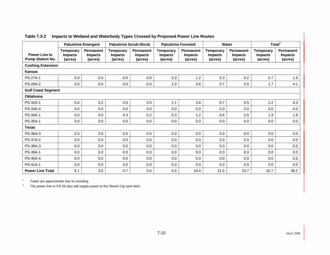
Table 7.3-3 Impacts to Wetland and Waterbody Types Crossed by Proposed Power Line Routes
Palustrine Emergent Palustrine Scrub-Shrub Palustrine Forested Water Total1
Power Line to Pump Station No.
Temporary Impacts (acres)
Permanent Impacts (acres)
Temporary Impacts (acres)
Permanent Impacts (acres)
Temporary Impacts (acres)
Permanent Impacts (acres)
Temporary Impacts (acres)
Permanent Impacts (acres)
Temporary Impacts (acres)
Permanent Impacts (acres)
Steele City Segment Montana PS-09 1.3 1.0 0.0 0.0 0.0 0.0 3.4 2.4 4.7 3.4 PS-10A-1 0.4 0.2 0.4 0.2 0.0 0.0 2.1 1.5 2.8 1.9 PS-11 0.0 0.0 0.0 0.0 0.0 0.0 1.6 1.0 1.6 1.0 PS-12 0.0 0.0 0.0 0.0 0.0 0.0 0.0 0.0 0.0 0.0 PS-13A-2 0.0 0.0 0.0 0.0 0.0 0.0 0.8 0.5 0.8 0.5 PS-14A-1 0.0 0.0 0.0 0.0 0.0 0.0 0.6 0.5 0.6 0.5 South Dakota PS-15A-2 0.0 0.0 0.0 0.0 0.0 0.0 2.1 1.7 2.1 1.7 PS-16 0.0 0.0 0.0 0.0 0.0 0.0 2.4 1.9 2.4 1.9 PS-17A-2 0.3 0.2 0.0 0.0 0.0 0.0 0.3 0.2 0.7 0.5 PS-18 0.3 0.2 0.0 0.0 0.0 0.0 1.0 0.7 1.3 1.0 PS-19A-3 0.0 0.0 0.0 0.0 0.0 0.0 1.0 0.7 1.0 0.7 PS-20A-2 1.4 1.0 0.0 0.0 0.7 2.4 0.3 0.2 2.4 3.6 PS-21A-1 0.3 0.2 0.0 0.0 0.3 1.2 0.3 0.2 1.0 1.7 Nebraska PS-22 0.3 0.2 0.0 0.0 0.0 0.0 0.0 0.0 0.3 0.2 PS-23 0.3 0.2 0.0 0.0 0.3 1.2 0.7 0.5 1.4 1.9 PS-24A-1 0.0 0.0 0.0 0.0 0.7 2.4 1.6 1.2 2.3 3.6 PS-25A-1 0.0 0.0 0.0 0.0 0.4 1.2 0.4 0.2 0.7 1.5 PS-26/Steele City Tank Farm2 0.0 0.0 0.0 0.0 0.3 1.2 0.6 0.5 0.9 1.7
7-10 July 6, 2009
Table 7.3-3 Impacts to Wetland and Waterbody Types Crossed by Proposed Power Line Routes
Palustrine Emergent Palustrine Scrub-Shrub Palustrine Forested Water Total1
Power Line to Pump Station No.
Temporary Impacts (acres)
Permanent Impacts (acres)
Temporary Impacts (acres)
Permanent Impacts (acres)
Temporary Impacts (acres)
Permanent Impacts (acres)
Temporary Impacts (acres)
Permanent Impacts (acres)
Temporary Impacts (acres)
Permanent Impacts (acres)
Cushing Extension Kansas PS-27A-1 0.0 0.0 0.0 0.0 0.3 1.2 0.3 0.2 0.7 1.5 PS-29A-2 0.0 0.0 0.0 0.0 1.0 3.6 0.7 0.5 1.7 4.1 Gulf Coast Segment Oklahoma PS-32A-1 0.4 0.2 0.0 0.0 1.1 3.6 0.7 0.5 2.2 4.3 PS-33A-4 0.0 0.0 0.0 0.0 0.0 0.0 0.0 0.0 0.0 0.0 PS-34A-1 0.0 0.0 0.3 0.2 0.3 1.2 0.6 0.5 1.3 1.9 PS-35A-1 0.0 0.0 0.0 0.0 0.0 0.0 0.0 0.0 0.0 0.0 Texas PS-36A-3 0.0 0.0 0.0 0.0 0.0 0.0 0.0 0.0 0.0 0.0 PS-37A-2 0.0 0.0 0.0 0.0 0.0 0.0 0.0 0.0 0.0 0.0 PS-38A-3 0.0 0.0 0.0 0.0 0.0 0.0 0.0 0.0 0.0 0.0 PS-39A-1 0.0 0.0 0.0 0.0 0.0 0.0 0.0 0.0 0.0 0.0 PS-40A-4 0.0 0.0 0.0 0.0 0.0 0.0 0.0 0.0 0.0 0.0 PS-41A-1 0.0 0.0 0.0 0.0 0.0 0.0 0.0 0.0 0.0 0.0 Power Line Total 5.1 3.6 0.7 0.5 5.5 19.4 21.5 15.7 32.7 39.2
1 Totals are approximate due to rounding. 2 The power line to PS-26 also will supply power to the Steele City tank farm.

7-11 July 6, 2009
Potential collision and electrocution impacts to bird species from the Project could be reduced further if electrical service providers agree to implement the following mitigation measures.
• Incorporation of standard, safe designs, as outlined in Suggested Practice for Raptor Protection on Power Lines (APLIC 1996), into the design of electrical distribution lines in areas of identified avian concern to prevent electrocution of raptor species attempting to perch on the power poles and lines. These measures include, but are not limited to, a 60-inch separation between conductors and/or grounded hardware and recommended use of insulating materials and other applicable measures depending on line configuration (APLIC 1996).
• Incorporation of standard raptor-proofing designs, as outlined in Mitigating Bird Collision with Power Lines (APLIC 1994), into the design of the electrical distribution lines to prevent collision to foraging and migrating raptors within the Project area, as applicable.
In addition to electrocution and collision impacts, power lines may have impacts to grouse species occurring along the route. According to the final management plan and conservation strategies for sage grouse in Montana (MSGWG 2005: “Power lines provide additional hunting perches for raptors in otherwise treeless areas. Power lines most likely impact grouse near leks, in brood-rearing habitat, and in wintering areas that also support large numbers of wintering raptors.”)
7.3.7 Land Use and Ownership
7.3.7.1 Ownership
Lands crossed by the proposed power line routes are summarized by ownership in Table 7.3-4. No tribal lands have been identified along the preliminary routes. The proposed routes primarily are on private lands.
Table 7.3-4 Ownership of Lands Crossed by Proposed Power Line Routes
Ownership (miles) Power Line to Pump Station No. Federal State Private Total1
Steele City Segment Montana PS-09 28.4 2.1 31.9 62.4 PS-10A-1 7.9 12.4 30.8 51.0 PS-11 5.9 1.3 4.8 12.0 PS-12 0.0 0.9 2.4 3.3 PS-13A-2 <0.1 0.0 13.5 13.5 PS-14A-1 0.0 1.0 4.2 5.2 South Dakota PS-15A-2 0.2 2.6 20.2 23.0 PS-16 1.5 9.0 35.2 45.7 PS-17A-2 0.0 0.0 11.0 11.0 PS-18 0.0 0.0 25.9 25.9 PS-19A-3 0.0 0.0 20.2 20.2 PS-20A-2 0.0 0.0 15.9 15.9 PS-21A-1 0.0 0.0 20.1 20.1

7-12 July 6, 2009
Table 7.3-4 Ownership of Lands Crossed by Proposed Power Line Routes
Ownership (miles) Power Line to Pump Station No. Federal State Private Total1
Nebraska PS-22 0.0 0.0 7.4 7.4 PS-23 0.0 0.0 23.0 23.0 PS-24A-1 0.0 0.0 10.1 10.1 PS-25A-1 0.0 0.0 14.3 14.3 PS-26/Steele City Tank Farm2
0.0 0.0 13.3 13.3
Keystone Cushing Extension Kansas PS-27A-1 0.0 0.0 10.2 10.2 PS-29A-2 0.0 0.0 11.2 11.2 Gulf Coast Segment Oklahoma PS-32A-1 0.0 0.0 6.9 6.9 PS-33A-4 0.0 0.0 0.6 0.6 PS-34A-1 0.0 0.0 5.3 5.3 PS-35A-1 0.0 0.0 4.1 4.1 Texas PS-36A-3 0.0 0.0 7.3 7.3 PS-37A-2 0.0 0.0 0.1 0.1 PS-38A-3 0.0 0.0 0.2 0.2 PS-39A-1 0.0 0.0 5.2 5.2 PS-40A-4 0.0 0.0 0.3 0.3 PS-41A-1 0.0 0.0 0.4 0.4 Power Line Total 44.0 29.3 356.0 429.2
1 Discrepancies in total mileage due to rounding. 2 The electrical power line to PS-26 also will supply power to Steele City tank farm.
Impacts to private and public land resources will mostly be limited to visual resources, because ground disturbance will only occur at utility locations. Utility locations include poles in remote areas, and service drops in more a populated areas. Utility locations will be selected to avoid most areas of concern. Table 7.3-4 summarizes approximate ownership impacts by mile as a result of construction and operational-related activities based on assumptions provided in Section 7.3, Affected Environment and Environmental Consequences. Table 7.3-5 summarizes acres of the same impacts.

7-13 July 6, 2009
Table 7.3-5 Impacts to Ownership of Lands Crossed by Proposed Power Line Routes
Federal State Private Total1
Power Line to Pump Station No.
Temporary Impacts (acres)
Permanent Impacts (acres)
Temporary Impacts (acres)
Permanent Impacts (acres)
Temporary Impacts (acres)
Permanent Impacts (acres)
Temporary Impacts (acres)
Permanent Impacts (acres)
Steele City Segment Montana PS-09 95.5 68.8 7.1 5.1 107.3 77.3 209.8 151.3 PS-10A-1 27.7 19.6 43.5 30.8 108.0 76.6 179.2 127.0 PS-11 23.6 15.3 5.2 3.4 19.2 12.4 48.0 31.0 PS-12 0.0 0.0 3.9 2.2 10.5 5.8 14.4 8.0 PS-13A-2 0.4 0.2 0.0 0.0 54.1 32.7 54.5 33.0 PS-14A-1 0.0 0.0 3.2 2.4 13.4 10.2 16.6 12.6 South Dakota PS-15A-2 0.6 0.5 7.8 6.3 60.4 49.0 68.8 55.8 PS-16 4.5 3.6 26.9 21.8 105.2 85.3 136.6 110.8 PS-17A-2 0.0 0.0 0.0 0.0 38.1 26.7 38.1 26.7 PS-18 0.0 0.0 0.0 0.0 83.0 62.8 83.0 62.8 PS-19A-3 0.0 0.0 0.0 0.0 68.8 50.9 68.8 50.9 PS-20A-2 0.0 0.0 0.0 0.0 55.8 39.5 55.8 39.5 PS-21A-1 0.0 0.0 0.0 0.0 68.5 49.7 68.5 49.7 Nebraska PS-22 0.0 0.0 0.0 0.0 21.1 24.7 21.1 24.7 PS-23 0.0 0.0 0.0 0.0 79.8 57.7 79.8 57.7 PS-24A-1 0.0 0.0 0.0 0.0 34.4 27.4 34.4 27.4 PS-25A-1 0.0 0.0 0.0 0.0 53.7 36.6 53.7 36.6 PS-26/Steele City Tank Farm2
0.0 0.0 0.0 0.0 39.5 36.1 39.5 36.1

7-14 July 6, 2009
Table 7.3-5 Impacts to Ownership of Lands Crossed by Proposed Power Line Routes
Federal State Private Total1
Power Line to Pump Station No.
Temporary Impacts (acres)
Permanent Impacts (acres)
Temporary Impacts (acres)
Permanent Impacts (acres)
Temporary Impacts (acres)
Permanent Impacts (acres)
Temporary Impacts (acres)
Permanent Impacts (acres)
Cushing Extension Kansas PS-27A-1 0.0 0.0 0.0 0.0 35.7 28.6 35.7 28.6 PS-29A-2 0.0 0.0 0.0 0.0 38.7 28.1 38.7 28.1 Gulf Coast Segment Oklahoma PS-32A-1 0.0 0.0 0.0 0.0 27.4 23.5 27.4 23.5 PS-33A-4 0.0 0.0 0.0 0.0 3.4 6.5 3.4 6.5 PS-34A-1 0.0 0.0 0.0 0.0 18.3 27.4 18.3 27.4 PS-35A-1 0.0 0.0 0.0 0.0 16.4 21.6 16.4 21.6 Texas PS-36A-3 0.0 0.0 0.0 0.0 43.8 21.3 43.8 21.3 PS-37A-2 0.0 0.0 0.0 0.0 1.4 1.2 1.4 1.2 PS-38A-3 0.0 0.0 0.0 0.0 2.8 0.5 2.8 0.5 PS-39A-1 0.0 0.0 0.0 0.0 24.5 25.0 24.5 25.0 PS-40A-4 0.0 0.0 0.0 0.0 4.2 0.7 4.2 0.7 PS-41A-1 0.0 0.0 0.0 0.0 3.5 1.0 3.5 1.0 Power Line Total 151.7 108.1 96.7 72.0 1,216.2 9463.9 1,464.6 1,127.0
1 Totals are approximate due to rounding. 2 The power line to PS-26 also will supply power to the Steele City tank farm.

7-15 July 6, 2009
Visual Resources
Visual resources are those characteristics of the landscape visible to residents and visitors. Descriptions of visual resources include the aesthetic value of the natural and developed landscape, the public value of viewing the natural landscape, and the visibility of the landscape from sensitive viewpoints (e.g., residences, recreation areas, rivers, and highways). The potential visual effects of the power lines include evaluation of physical features of the landscape, with particular attention to the ability of the particular landscape to absorb the visual modifications that will be introduced, together with the level of concern, or sensitivity, people have for scenic quality. Together these factors define the degree of landscape modification that will be acceptable. Table 7.3-6 shows the BLM VRM classes located along power lines located on federal lands.
Table 7.3-6 VRM Classes on Federal Lands Crossed by Electrical Power Lines
Power Line to Pump Station No.
Land Management Agency
Approximate Milepost VRM Class
Steele City Segment
PS-09 Bureau of Reclamation 0.0 to 0.0 4
PS-09 BLM 0.0 to 1.3 4
PS-09 BLM 1.4 to 1.7 4
PS-09 BLM 4.5 to 5.1 3
PS-09 BLM 5.5 to 5.7 3
PS-09 BLM 6.4 to 8.0 3
PS-09 BLM 9.9 to 10.9 3
PS-09 BLM 12.9 to 14.4 3
PS-09 Bureau of Reclamation 17.3 to 17.4 3
PS-09 Bureau of Reclamation 18.3 to 18.8 3
PS-09 BLM 22.4 to 22.7 3
PS-09 BLM 23.6 to 23.9 3
PS-09 BLM 26.6 to 26.7 3
PS-09 BLM 26.9 to 29.4 3
PS-09 BLM 31.6 to 31.9 3
PS-09 BLM 32.9 to 34.7 3
PS-09 BLM 34.9 to 35.4 3
PS-09 BLM 36.2 to 36.6 3
PS-09 BLM 36.8 to 37.2 3
PS-09 BLM 38.2 to 40.2 3
PS-09 BLM 40.7 to 41.4 3
PS-09 BLM 42.6 to 47.8 3
PS-09 BLM 48.0 to 48.2 3

7-16 July 6, 2009
Table 7.3-6 VRM Classes on Federal Lands Crossed by Electrical Power Lines
Power Line to Pump Station No.
Land Management Agency
Approximate Milepost VRM Class
PS-09 BLM 48.2 to 48.4 3
PS-09 BLM 50.6 to 51.2 3
PS-09 BLM 51.7 to 52.7 3
PS-09 BLM 53.2 to 55.9 3
PS-09 BLM 56.9 to 57.4 3
PS-09 BLM 59.4 to 60.4 3
PS-09 BLM 61.4 to 62.4 3
PS-10A-1 BLM 10.0 to 10.5 4
PS-10A-1 BLM 26.7 to 27.7 4
PS-10A-1 BLM 29.0 to 30.5 4
PS-10A-1 BLM 30.7 to 30.8 4
PS-10A-1 BLM 43.5 to 44.6 4
PS-10A-1 BLM 45.6 to 46.9 4
PS-10A-1 BLM 47.4 to 47.9 4
PS-10A-1 BLM 48.5 to 50.6 4
PS-11 US Department of Defense 2.5 to 2.9 2
PS-11 BLM 2.9 to 4.1 2
PS-11 BLM 4.1 to 4.4 4
PS-11 BLM 4.9 to 5.2 3
PS-11 BLM 6.2 to 8.4 3
PS-11 BLM 8.5 to 9.4 3
PS-11 BLM 9.6 to 10.4 3
PS-13A-2 BLM 6.7 to 6.7 2
PS-15A-2 BLM 20.1 to 20.4 Unclassified
PS-16 BLM 2.2 to 3.2 Unclassified
PS-16 BLM 20.8 to 21.1 Unclassified
PS-16 BLM 43.3 to 43.6 Unclassified
There are no formal guidelines for managing visual resources for private or state owned lands. As described in Section 3.7, the BLM is responsible for identifying and protecting scenic values on public lands under several provisions of the Federal Land Policy Management Act (FLPMA) and the NEPA. Preliminary evaluations of visual impacts from power lines are in process. Results based on VRM classifications will be provided to BLM

7-17 July 6, 2009
in their POD and will be fully determined as required for incremental permits applied for by individual power utilities.
7.3.7.2 Land Use
Land uses crossed by the preliminary power line routes are classified as described in Section 3.7. Table 7.3-7 provides the miles crossed by the power line routes categorized by land use. Table 7.3-7 summarizes approximate miles of land use impacts as a result of construction and operational-related activities based on assumptions provided in Section 7.3, Affected Environment and Environmental Consequences. Table 7.3-8 summarizes acres of the same impacts.
Table 7.3-7 Land Use Types Crossed by the Proposed Power Line Routes
Power Line to Pump Station No.
Dev
elop
ed
(mile
s)
Agr
icul
ture
/ C
ropl
and
(mile
s)
Ran
gela
nd/
Gra
ssla
nd
(mile
s)
Fore
st L
and
(mile
s)
Wat
er (m
iles)
Wet
land
s (m
iles)
Total (miles)1
Steele City Segment
Montana
PS-09 0.7 6.4 53.8 0.0 1.1 0.4 62.4
PS-10A-1 4.4 16.9 28.6 0.3 0.6 0.2 51.0
PS-11 0.2 2.1 9.2 0.2 0.4 0.0 12.0
PS-12 0.2 1.4 1.7 0.0 0.0 0.0 3.3
PS-13A-2 0.4 2.7 10.1 0.0 0.2 0.0 13.5
PS-14A-1 0.0 0.7 4.3 0.0 0.2 0.0 5.2
South Dakota
PS-15A-2 1.2 1.5 19.6 0.0 0.7 0.0 23.0
PS-16 1.6 3.5 39.8 0.0 0.8 0.0 45.7
PS-17A-2 1.0 1.9 7.9 0.0 0.1 0.1 11.0
PS-18 8.0 10.3 7.3 0.0 0.3 0.1 25.9
PS-19A-3 0.6 4.0 15.0 0.2 0.3 0.0 20.2
PS-20A-2 1.1 7.9 6.2 0.1 0.1 0.5 15.9
PS-21A-1 4.1 6.7 8.9 0.1 0.1 0.2 20.1
Nebraska
PS-22 0.0 4.6 2.1 0.7 0.0 0.1 7.4
PS-23 0.3 5.1 16.9 0.2 0.2 0.2 23.0
PS-24A-1 1.8 3.1 4.3 0.3 0.5 0.3 10.1

7-18 July 6, 2009
Table 7.3-7 Land Use Types Crossed by the Proposed Power Line Routes
Power Line to Pump Station No.
Dev
elop
ed
(mile
s)
Agr
icul
ture
/ C
ropl
and
(mile
s)
Ran
gela
nd/
Gra
ssla
nd
(mile
s)
Fore
st L
and
(mile
s)
Wat
er (m
iles)
Wet
land
s (m
iles)
Total (miles)1
PS-25A-1 1.0 12.1 0.8 0.2 0.1 0.1 14.3
PS-26/Steele City Tank Farm2
1.3 7.5 3.7 0.4 0.2 0.1 13.3
Keystone Cushing Extension
Kansas
PS-27A-1 1.7 6.4 1.5 0.4 0.1 0.1 10.2
PS-29A-2 0.3 2.6 7.7 0.1 0.2 0.3 >11.2
Gulf Coast Segment
Oklahoma
PS-32A-1 2.2 0.0 3.6 0.7 0.2 0.3 6.9
PS-33A-4 0.1 0.0 0.2 0.4 0.0 0.0 0.6
PS-34A-1 0.2 0.0 3.3 1.5 0.2 0.2 5.3
PS-35A-1 0.4 0.0 2.6 1.2 0.0 0.0 4.1
Texas
PS-36A-3 0.2 2.7 4.2 0.2 0.0 0.0 7.3
PS-37A-2 0.0 0.0 0.0 0.1 0.0 0.0 0.1
PS-38A-3 0.0 0.0 0.2 0.0 0.0 0.0 0.2
PS-39A-1 2.0 1.3 0.6 1.4 0.0 0.0 5.2
PS-40A-4 0.2 0.1 0.0 0.0 0.0 0.0 0.3
PS-41A-1 0.0 0.4 0.0 0.0 0.0 0.0 0.4
Power Line Total 35.2 111.9 264.1 8.7 6.5 3.3 429.7 1 Totals are approximate due to rounding. 2 The power line to PS-26 also will supply power to the Steele City tank farm. Note: Entries provided herein are based on Land Use/Land Cover analyses in combination with field verification. The “Developed” category includes developed lands including ROW (DROW), industrial (DIND), commercial (DCOM), and residential (DRES) areas; “Agriculture/Cropland” category includes actively cultivated land (CROP) and center pivot irrigation systems (PCROP); “Rangeland/Grassland” category includes grassland (GR) and native grassland ecosystems (NGR); “Forest Land” includes upland forests (UF) and windbreaks (WB); “Water” category includes ephemeral (EPH) , intermittent (INT), open water (OW), and perennial (PER) waterbodies and man-made structures (MABO and MADI); and “Wetlands” category includes palustrine emergent (PEM), scrub-shrub (PSS) , and forested (PFO) wetlands.

7-19 July 6, 2009
Table 7.3-8 Impacts to Land Use Types Crossed by Proposed Power Line Routes
Developed Agriculture/
Cropland Rangeland/ Grassland Forest Land Water Wetlands Total1
Power Line to Pump
Station No.
Temp. Impacts (acres)
Perm. Impacts (acres)
Temp. Impacts (acres)
Perm. Impacts (acres)
Temp. Impacts (acres)
Perm. Impacts (acres)
Temp Impacts (acres)
Perm. Impacts (acres)
Temp. Impacts (acres)
Perm. Impacts (acres)
Temp. Impacts (acres)
Perm. Impacts (acres)
Temp. Impacts (acres)
Perm. Impacts (acres)
Steele City Segment
Montana
PS-09 2.4 1.7 21.6 15.5 181.2 130.6 0.0 0.0 3.4 2.4 1.3 1.0 209.8 151.3
PS-10A-1 15.5 10.7 59.4 41.1 100.5 69.6 1.1 3.6 2.1 1.5 0.7 0.5 179.2 127.0
PS-11 0.8 0.5 8.2 5.0 35.7 22.1 0.8 2.4 1.6 1.0 0.0 0.0 47.0 31.0
PS-12 0.8 0.5 5.7 3.4 6.9 4.1 0.0 0.0 0.0 0.0 0.0 0.0 13.4 8.0
PS-13A-2 1.6 1.0 10.7 6.6 40.0 24.7 0.0 0.0 0.8 0.5 0.0 0.0 53.1 32.7
PS-14A-1 0.0 0.0 2.1 1.7 12.9 10.4 0.0 0.0 0.6 0.5 0.0 0.0 15.6 12.6
South Dakota
PS-15A-2 3.5 2.9 4.4 3.6 57.7 47.5 0.0 0.0 2.1 1.7 0.0 0.0 67.8 55.8
PS-16 4.7 3.9 10.5 8.5 118.1 96.5 0.0 0.0 2.4 1.9 0.0 0.0 135.6 110.8
PS-17A-2 3.4 2.4 6.4 4.6 26.6 19.2 0.0 0.0 0.3 0.2 0.3 0.2 37.1 26.7
PS-18 25.2 19.3 32.5 24.9 23.0 17.6 0.0 0.0 0.9 0.7 0.3 0.2 82.0 62.8
PS-19A-3 2.0 1.5 13.5 9.7 50.6 36.5 0.7 2.4 1.0 0.7 0.0 0.0 67.8 50.9
PS-20A-2 3.8 2.7 27.1 19.0 21.2 14.9 0.3 1.2 0.3 0.2 2.1 3.4 54.8 41.5
PS-21A-1 13.8 9.9 22.5 16.2 29.9 21.6 0.3 1.2 0.3 0.2 0.7 1.5 67.5 50.7
Nebraska
PS-22 0.0 0.0 12.9 11.0 5.9 5.0 2.0 8.5 0.0 0.0 0.3 0.2 21.1 24.7
PS-23 1.0 0.7 17.5 12.4 58.1 41.1 0.7 2.4 0.7 0.5 0.7 1.5 78.8 58.7
PS-24A-1 5.9 4.3 10.2 7.4 14.1 10.3 1.0 3.6 1.7 1.2 0.7 2.4 33.4 29.3
PS-25A-1 3.7 2.4 44.6 29.3 2.9 1.9 0.7 2.4 0.4 0.2 0.4 1.2 52.7 37.6
PS-26/ Steele City Tank Farm2
3.8 3.2 21.9 18.3 10.8 9.0 1.2 4.9 0.6 0.5 0.3 1.2 38.5 37.1

7-20 July 6, 2009
Table 7.3-8 Impacts to Land Use Types Crossed by Proposed Power Line Routes
Developed Agriculture/
Cropland Rangeland/ Grassland Forest Land Water Wetlands Total1
Power Line to Pump
Station No.
Temp. Impacts (acres)
Perm. Impacts (acres)
Temp. Impacts (acres)
Perm. Impacts (acres)
Temp. Impacts (acres)
Perm. Impacts (acres)
Temp Impacts (acres)
Perm. Impacts (acres)
Temp. Impacts (acres)
Perm. Impacts (acres)
Temp. Impacts (acres)
Perm. Impacts (acres)
Temp. Impacts (acres)
Perm. Impacts (acres)
Cushing Extension
Kansas
PS-27A-1 5.8 4.1 21.8 15.5 5.1 3.6 1.4 4.8 0.3 0.2 0.3 1.2 34.7 29.6
PS-29A-2 1.0 0.7 9.0 6.3 26.6 18.7 0.3 1.2 0.7 0.5 1.0 3.6 38.7 31.0
Gulf Coast Segment
Oklahoma
PS-32A-1 8.2 5.2 0.0 0.0 13.4 8.5 2.6 8.4 0.7 0.5 1.5 3.9 26.4 26.4
PS-33A-4 0.3 0.2 0.0 0.0 0.6 0.4 1.5 5.9 0.0 0.0 0.0 0.0 2.4 6.5
PS-34A-1 0.6 0.5 0.0 0.0 10.6 7.9 4.8 18.1 0.6 0.5 0.6 1.4 17.3 28.4
PS-35A-1 1.5 0.9 0.0 0.0 9.5 6.2 4.4 14.5 0.0 0.0 0.0 0.0 15.4 21.6
Texas
PS-36A-3 1.2 0.5 15.8 6.5 24.6 10.2 1.2 3.3 0.0 0.0 0.0 0.0 42.8 20.5
PS-37A-2 0.0 0.0 0.0 0.0 0.0 0.0 1.4 1.2 0.0 0.0 0.0 0.0 0.4 1.2
PS-38A-3 0.0 0.0 0.0 0.0 1.8 0.5 0.0 0.0 0.0 0.0 0.0 0.0 1.8 0.5
PS-39A-1 9.0 4.8 5.9 3.1 2.7 1.4 5.9 15.7 0.0 0.0 0.0 0.0 23.5 25.0
PS-40A-4 2.1 0.5 1.1 0.2 0.0 0.0 0.0 0.0 0.0 0.0 0.0 0.0 3.2 0.7
PS-41A-1 0.0 0.0 2.5 1.0 0.0 0.0 0.0 0.0 0.0 0.0 0.0 0.0 2.5 1.0
Power Line Total
121.6 85.0 387.5 271.2 891.2 640.2 31.1 105.9 21.5 15.7 11.2 23.5 1,464.2 1,141.5
1 Totals are approximate due to rounding. 2 The power line to PS-26 also will supply power to the Steele City tank farm.

7-21 July 6, 2009
7.3.7.3 Developed Land/Residential/Commercial Areas
Table 7.3-9 provides a summary of the structures within 50 feet of the proposed power line routes, based on aerial interpretation and field surveys where available.
Table 7.3-9 Natural and Human Resources Potentially Affected by Proposed Power Line Routes
Proposed Power Line Route
Power Line to Pump Station No.
Utility Supply
(kV)
Number of Structures within
50 Feet Other Resources Issues
Steele City Segment
Montana
PS-09 115 7 Crosses BLM, Bureau of Reclamation, and Montana State Trust lands.
PS-10A-1 115 5 Crosses BLM and, Montana State Trust lands.
PS-11 115 0 Crosses BLM, Department of Defense (USACE), and Montana State Trust lands.
PS-12 115 3 Crosses Montana State Trust lands.
PS-13A-2 115 0 Crosses BLM lands.
PS-14A-1 115 0 Crosses Montana State Trust lands.
South Dakota
PS-15A-2 115 0 Crosses BLM and South Dakota Game, Fish, and Parks lands.
PS-16 115 0 Crosses BLM; South Dakota Game, Fish, and Parks lands; and State School land.
PS-17A-2 115 0 None
PS-18 115 1 None
PS-19A-3 115 11 None
PS-20A-2 115 8 None
PS-21A-1 115 15 None
Nebraska
PS-22 115 0 None
PS-23 115 6 None
PS-24A-1 115 1 None
PS-25A-1 69 5 None
PS-26/Steele City Tank Farm1
115 0 None

7-22 July 6, 2009
Table 7.3-9 Natural and Human Resources Potentially Affected by Proposed Power Line Routes
Proposed Power Line Route
Power Line to Pump Station No.
Utility Supply
(kV)
Number of Structures within
50 Feet Other Resources Issues
Cushing Extension
Kansas
PS-27A-1 115 0 None
PS-29A-2 115 6 None
Gulf Coast Segment
Oklahoma
PS-32A-1 138 0 None
PS-33A-4 138 0 None
PS-34A-1 138 0 None
PS-35A-1 138 5 None
Texas
PS-36A-3 138 1 None
PS-37A-2 138 3 None
PS-38A-3 138 4 None
PS-39A-1 138 0 None
PS-40A-4 138 0 None
PS-41A-1 240 0 None 1 The electrical power line to PS-26 also will supply power to Steele City tank farm.
Concerns associated with routing power lines close to residences within populated areas are related to associated electromagnetic fields (EMF). Routing and siting information related to electromagnetic and inductive mitigation on the power lines and radio communication serving the Project pump stations is provided below.
Electromagnetic induction does occur from power lines. The potential radio and television interference, as well as noise interference, is mitigated by keeping power lines located away from residences (500 feet minimum, if possible). Power lines are routed to keep parallel metallic plant (pipelines, metallic cable, fences) at a minimum. On fences, when paralleling the power line, the metallic wire is grounded (driven ground electrode) at least four times per mile. When crossing fences, the metallic wire is grounded using a 5-foot (minimum) ground electrode. Whenever possible, a 100-foot-wide right-of-way for the 115-kV power lines will be obtained to minimize any future installation of facilities that could be affected by induction.
There are three potential influences on a communication (metallic) plant in the vicinity of a power line. These are inductive influence, coupling, and susceptiveness. The power providers will work closely with sister utilities to determine the route of existing cable plant. Routing takes into account other utilities and keeps separation

7-23 July 6, 2009
between the two different types of plant. Montana state law requires that the Project Engineer obtain as-built information from other utilities. This allows the Design Engineer to mitigate inductive influences. Avoiding paralleling facilities for long distances (over 10 miles) is one method of reducing the susceptiveness to communication plant. Shielded telephone cables reduce coupling with nearby power lines. This helps to reduce coupling caused by close spacings.
Harmonic and waveform distortion may occur due to rectifier action of solid-state motor speed controllers. Harmonic mitigation measures are required on all large loads. Experience with the Express Pipeline indicates that when the harmonic filters tripped off line, noise built to levels that effectively shut down the telephone communications. Close cooperation between the consumers (large motor loads) and the power providers will mitigate such harmonic potential. Harmonic filters will be required based upon measured system harmonic influence levels.
No impacts are expected from the radio communication systems at the Keystone Facilities with regard to electrical and magnetic fields. The only electromagnetic field emitted from radio antennas is the normal radio frequency signal as licensed by the FCC.
The C-filter on communication systems eliminates the 60 hz induced noise, but not the harmonics on a telephone system. The system is terminated in delta – wye configurations. This keeps the phase currents relatively balanced. Mitigation efforts on the distribution circuits will include phase balancing.
Power line Radio Frequency Interference (RFI) is usually caused by sparking (arcs). Typically, this is caused by loose hardware. The power provider design generally uses spring washers to keep hardware tight.
Conductor supports use trunion clamps and AGS factory preformed clamps to keep the conductor and support clamps with a firm contact between the two entities at all times to mitigate arcing sources. At the 115-kV level, corona is usually not a major issue. Corona in itself is not a major source of RFI. Defective lightning arrestors also contribute to RFI. The power providers use a static conductor at the top of the pole to mitigate lightning-caused flashovers. Lightning arrestors are limited to the stations where major equipment is located.
These are some of the measures that are incorporated in the line design to minimize the inductive and noise-causing potential to communication and other affected facilities.
The radio communication systems at Project pump stations will operate on specific frequencies licensed by the FCC. This minimizes the risk of any interference with radio, television, or any other communication systems in the area, as well as providing for a process if any interference should occur.
7.3.7.4 Noise
The existing noise environment will be similar to levels described in Section 3.7.5. Electrical power line operation is not anticipated to increase ambient noise.
7.3.8 Cultural Resources Federal guidelines for the protection of cultural resources as described in Section 3.8 will apply to construction and operation of power lines. Power providers will comply with this guidance. Results of field surveys are reported in Appendix G. Where required, Native American consultation will occur through appropriate agency consultation.
The following table outlines cultural resource sites as identified during field surveys and/or file/record searches. No power line surveys have been conducted to date in Nebraska, Kansas, or Oklahoma; therefore, only file/record search data has been provided for those states. During the duration of field surveys, numerous sites were recorded; however, only those sites that intersect the currently proposed 300-foot-wide power line study

7-24 July 6, 2009
area are referenced below. Currently, the Project has located 24 potentially eligible resources and 12 eligible sites. Visual analysis may be needed on sites that may be considered traditional cultural properties, as power lines may affect NRHP criteria associated with these locations. Potentially eligible and eligible sites identified during field surveys and or file/records searches that intersect the currently proposed 300-foot-wide power line study area are summarized below in Table 7.3-10.
Table 7.3-10 Potentially Eligible and Eligible Archaeological Sites within or Immediately Adjacent to the Power Line Study Area
Power Line to Pump Station No. Site Number Site Name or Description
Relation to Survey Area Status
Steele City Segment
Montana
PS-09 24PH2710 Irrigation Within Eligible
PS-09 24PH3008 Railway Within Eligible
PS-09 24PH3103 (24VL1375)
Irrigation Within Eligible
PS-09 24PH4167 Railroad grade Within Eligible
PS-09 24PH4233 Stone feature Within Potentially Eligible
PS-09 24PH3008 Railway Within Potentially Eligible
PS-09 24PH4164 Rock cairn Within Potentially Eligible
PS-09 24PH4165 Rock cairn Within Potentially Eligible
PS-09 24PH4166 Stone circle Within Potentially Eligible
PS-09 24PH4168 Stone circle Within Potentially Eligible
PS-09 24PH4169 Stone feature/artifact Within Potentially Eligible
PS-09 24PH4225 Stone circle Within Potentially Eligible
PS-09 24PH4228 Stone circle Within Potentially Eligible
PS-09 24PH4230 Stone circle Within Potentially Eligible
PS-09 24PH4231 Stone circle Within Potentially Eligible
PS-09 24PH4232 Stone circle Within Potentially Eligible
PS-09 24PH4235 Rock cairn Within Potentially Eligible
PS-09 24PH4222 Rock cairn Within Potentially Eligible
PS-09 24PH4226 Stone feature Within Potentially Eligible
PS-09 24PH4229 Stone circle Within Potentially Eligible
PS-10A-1 24VL99-11 Railroad Within Eligible
PS-10A-1 24VL99-6 Railroad Within Eligible
PS-10A-1 24VL1914 Stone feature Within Potentially Eligible
PS-10A-1 24VL1915 Stone feature Within Potentially Eligible

7-25 July 6, 2009
Table 7.3-10 Potentially Eligible and Eligible Archaeological Sites within or Immediately Adjacent to the Power Line Study Area
Power Line to Pump Station No. Site Number Site Name or Description
Relation to Survey Area Status
PS-10A-1 24VL1916 Stone circle Within Potentially Eligible
PS-10A-1 24VL1917 Stone circle Within Potentially Eligible
24VL1919/ PS-10A-1
24VL1909
Stone circle Within Potentially Eligible
PS-10A-1 24VL1874 Historic homestead Unknown Undetermined
PS-10A-1 24VL1628 Railroad Within Eligible
PS-10A-1 24MC0097 Railroad Within Eligible
PS-10A-1 24VL99-9 Railroad Within Eligible
PS-10A-1 24VL99-7 Railroad Within Eligible
PS-10A-1 24VL1890 Historic artifact scatter N/A Not Eligible
PS-10A-1 24MC0277 Prehistoric lithic scatter Unknown Unresolved
PS-10A-1 24VL1294 Stone circle site Unknown, potential TCP
Undetermined
PS-10A-1 N/A Prehistoric IF N/A Not Eligible
PS-11 N/A N/A N/A N/A
PS-12 24MC0257 Railroad Within Eligible
PS-13A-2 N/A N/A N/A N/A
PS-14A-1 N/A N/A N/A N/A
South Dakota
PS-15A-2 N/A N/A N/A N/A
PS-16 N/A N/A N/A N/A
PS-17A-2 N/A N/A N/A N/A
PS-18 N/A N/A N/A N/A
PS-19A-3 N/A N/A N/A N/A
PS-20A-2 N/A N/A N/A N/A
PS-21 39GR0165 Homestead Within Eligible
PS-21 39GR0169 Homestead Within Eligible
PS-21 39TP0063 Homestead Within Eligible
Nebraska
PS-22 N/A N/A N/A N/A
PS-23 N/A N/A N/A N/A

7-26 July 6, 2009
Table 7.3-10 Potentially Eligible and Eligible Archaeological Sites within or Immediately Adjacent to the Power Line Study Area
Power Line to Pump Station No. Site Number Site Name or Description
Relation to Survey Area Status
PS-24A-1 N/A N/A N/A N/A
PS-25A-1 N/A N/A N/A N/A
PS-26/Steele City Tank Farm1
N/A N/A N/A N/A
Cushing Extension
Kansas
PS-27A-1 14CY12 Stone mound Outside Potentially Eligible
PS-27A-1 14BU582 Lithic scatter Outside Unknown
PS-27A-1 14CY101 Stone mound Outside Unknown
PS-29A-2 14BU131 Farmstead/Rural household Adjacent Ineligible
Gulf Coast Segment2
Oklahoma3
PS-32A-1 N/A Silver Star Cemetery Within Unknown, Protected
PS-32A-1 N/A Church Within Unknown
PS-32A-1 N/A Railroad grade Within Unknown
PS-33A-4 N/A N/A N/A N/A
PS-34A-1 N/A House with outbuilding Adjacent Unknown
N/A Railroad grade Within Unknown
PS-35A-1 N/A GLO site leads – possible residence
Within Unknown
PS-35A-1 N/A GLO site leads – possible residence
Within Unknown
PS-35A-1 N/A Old Bennington Church Outside Listed or Eligible
PS-35A-1 N/A Cemetery Outside Unknown, Protected
PS-35A-1 N/A Historic standing structure Outside Potentially Eligible
Texas4
PS-36A-3 N/A N/A N/A N/A
PS-37A-2 41WD76 Prehistoric artifact scatter Within Unknown
PS-37A-2 41WD77 Prehistoric artifact scatter Within Unknown
PS-37A-2 N/A Railroad grade Within Unknown
PD-38A-3 N/A N/A N/A N/A

7-27 July 6, 2009
Table 7.3-10 Potentially Eligible and Eligible Archaeological Sites within or Immediately Adjacent to the Power Line Study Area
Power Line to Pump Station No. Site Number Site Name or Description
Relation to Survey Area Status
PS-39A-1 41NA64 Prehistoric artifact scatter Outside Unknown
PS-40A-4 N/A Railroad grade Within Unknown
PS-41A-1 N/A N/A N/A N/A 1 The power line to PS-26 also will supply power to the Steele City tank farm. 2 At the time of document production, the proposed 1,500-foot APE for power lines was still under review in terms on indirect impacts.
Once the APE is defined, an analysis will be submitted. 3 Information regarding cultural resources within and adjacent to the 300-foot-wide power line survey areas in Oklahoma was obtained
from the Oklahoma Archeological Society. 4 Information regarding cultural resources within and adjacent to the 300-foot-wide power line survey areas in Texas was obtained from
the Texas Archeological Research Laboratory.
7.3.9 Social and Economic Conditions Power line construction will primarily occur in locations described in Section 3.10. Because construction and operation of these power lines will be through local power providers, these power providers will be responsible for temporarily locating construction and maintenance personnel. Probable sources will include individuals already working for these companies. Construction of power lines could cause a brief increase in demand for local services due to construction personnel; however, the need for operational personnel will be determined by the individual power provider.
7.4 Cumulative Impacts Potential environmental impacts for the majority of the proposed power line routes are analogous to those described in Section 3.0, and are thus sufficiently characterized in that portion of the document. However, the individual wetlands and waterbodies affected by construction or maintenance of the proposed power lines may be subject to Section 404 permitting and are outlined in detail in Table 7.3-2. Discussions of cumulative impacts from the power lines associated with the Project are discussed in Section 5.0. Other than the Keystone Pipeline Project, no foreseeable construction projects that overlap in space and time with the power lines were identified.