7 Results of an Electrical Power System Fault Study · PDF fileResults of an Electrical Power...
46
1993 i ¢ _. z ! ......... Results of an Electrical Power System Fault Study (CDDF Final Report .r No. N06) S N.R. Dugal-Whitehead and Y.B. Johnson f " . _ , . (NASA-TP-3413) RESULTS OF AN ELECTRICAL POWER SYSTEM FAULT STUOY (CDDF) Final Report No. NO6 (NASA} 44 p ----7 =__ i N94-15007 Unclas https://ntrs.nasa.gov/search.jsp?R=19940010534 2018-05-09T18:04:37+00:00Z
Transcript of 7 Results of an Electrical Power System Fault Study · PDF fileResults of an Electrical Power...

1993
i
¢ _.
z
! .........
Results of an Electrical
Power System Fault Study
(CDDF Final Report
.r
No. N06)
S
N.R. Dugal-Whitehead
and Y.B. Johnson
f
" . _ , .
(NASA-TP-3413) RESULTS OF AN
ELECTRICAL POWER SYSTEM FAULT STUOY
(CDDF) Final Report No. NO6 (NASA}
44 p
----7
=__
i
N94-15007
Unclas
https://ntrs.nasa.gov/search.jsp?R=19940010534 2018-05-09T18:04:37+00:00Z

NASATechnical
Paper3413
1993
National Aeronautics andSpace Administration
Office of ManagementScientific and TechnicalInformation Program
Results of an Electrical
Power System Fault Study
(CDDF Final Report
No. N06)
N.R. Dugal-Whitehead and Y.B. Johnson
George C. Marshall Space Flight Center
Marshall Space Flight Center, Alabama

TABLE OF CONTENTS
I. INTRODUCTION ................................................................................................................
II. ELECTRICAL POWER SYSTEM FAULT STUDY ..........................................................
Page
A. Solar Array ..................................................................................................................... 1
1. Solar Array Parasitic Current Power Loss and Solar Array Corona Discharge ...... 2
2. Solar Array Electromagnetic Interference ............................................................... 3
3. Solar Array Degradation .......................................................................................... 3
4. Solar Array Panel Short ........................................................................................... 3
5. Solar Array Panel Open ........................................................................................... 3
6. Isolation Diode Open ............................................................................................... 37. Isolation Diode Short ............................................................................................... 3
B. Battery ............................................................................................................................ 41. Short Circuit ............................................................................................................. 5
2. Capacity Degradation .............................................................................................. 5
3. Energy Storage Failure .......................................... ................................................... 6C. Distribution .................................................................................................................... 6
1. Short of Bus to Neutral or Return, Short of Bus to Earth or Chassis
Ground, Loss of Ground to Neutral Bonding, and Multiple Neutralto Ground Connections ............................................................................................ 6
2. Short of One Bus or Line to Another ....................................................................... 7
3. Bus Switch Short and Bus Switch Open ............................. "..................................... 74. Soft Shorts of Bus or Line to Return or Ground ...................................................... 7
D. Loads .............................................................................................................................. 71. Short of Load to Neutral or Return and Short of Load to Chassis or
Earth Ground ........................................................................................................... 7
2. Open Circuit Failure of Load ................................................................................... 8
3. Soft Short of a Load ................................................................................................. 8
HI. LARGE AUTONOMOUS SPACECRAFT ELECTRICAL POWER SYSTEM ................ 8
A. Autonomously Managed Power System ........................................................................ 9B. Programmable Power Processor .................................................................................... 11
C. Space Station Module Power Management and Distribution ........................................ 12D. Fault Device ................................................................................................................... 15
1. Proposed Fault Injection Device .............................................................................. 15
2. Existing Fault Device .............................................................................................. 15
IV. FAULTS ................................................................................................................................ 17
A° First Year ....................................................................................................................... 17
1. Communication Faults ............................................................................................. 17
2. Battery Faults ........................................................................................................... 173. Load Faults .............................................................................................................. 18
,°°
Ill
I:N_C_IEDtN_ PAC._ B__ANK NOT FN_t_'.D

TABLE OF CONTENTS (Continued)
Vo
B° Second Year ...................................................................................................................1. Batteries ...................................................................................................................
2. Solar Array Simulator ..............................................................................................
3. Programmable Power Processor ..............................................................................4. Space Station Module Power Management and Distribution ..................................
a. Direct Shorts to Ground ......................................................................................
b. Shorted Rt_ ........................................................................................................c. I2t Fault ...............................................................................................................
(1) Power Distribution Control Unit .................................................................
(2) Load Center .................................................................................................d. Internal Failure of the RPC .................................................................................
e. Transients ............................................................................................................
5. Large Autonomous Spacecraft Electrical Power System ........................................
C. Third Year ......................................................................................................................
1. Creating Cascading Faults .......................................................................................
2. Faults Propogate ......................................................................................................a. 3 kW "Over Current" Then 1 kW "Fast Trip". ...................................................
b. 3 kW "Over Current'71 kW "Fast Trip". ............................................................
c. 3 kW "Over Current" Before 1 kW "Fast Trip". ................................................
d. Results of Actual Fault Testing .............................. _:...........................................
CONCLUSIONS ...................................................................................................................
A. Fault Study .................................................. .- .................................................................
B. Power System Testing ................................ _..................................................................
C. Cascading Faults ......................................... •..................................................................
REFERENCES ...............................................................................................................................
Page
19
19
20
2021
22
22
22
23
25
27
27
27
28
28
29
29
30
31
31
32
32
32
33
34
iv

Figure
1.
2.
3.
4.
5.
6.
7.
8.
9.
10.
11.
LIST OF ILLUSTRATIONS
Title
Simplified space station SA power system schematic .................................................
Present configuration of LASEPS ................................................................................
Autonomously managed power system .......................................................................
EPS configuration ........................................................................................................
Space station module power management and distribution breadboard ......................
120 Vdc current limiting RPC .....................................................................................
LASEPS annunciator panel ..........................................................................................
Example of how the faults are wired into the fault device ...........................................
3 kW RPS direct short to ground .................................................................................
3 kW RPC 4 ohm short to ground ................................................................................
1 kW RPC 14 ohm short to ground ..............................................................................
Page
2
9
10
11
13
14
16
16
23
24
26
V

A
Ah
AMPS
Bat.
CATV
CHG
CMD
CRRES
Cur
dc
div
DOD
DMSP 4
E/vli
EPS
EPSC
FELES
FET
FRAMES
FT
GC
HST
I
ABBREVIATIONS AND ACRONYMS
amperes
ampere hour
autonomously managed power system
battery
cable access television
charge controller
command
Combined Release and Radiation Effects Satellite
current
direct current
division
depth of discharge
undefined in source document
electromagnetic interference
electrical power system
electrical power system controller
front end load enable scheduler
field effect transistor
fault recovery and management expert system
fast trip (I at limit >15 ms)
generic card
Hubble space telescope
current
vi

ABBREVIATIONS AND ACRONYMS (Continued)
Inc.
INTELSAT
JPL
KANT
kHz
KNOMAD
kW
LASEPS
LC
LCC
LEO
LLP
LPLMS
mA
MAESTRO
mHz
min
ms
MSFC
NASA
Ni-Cd
Ni-H
NJ
Incorporated
International Telecommunications Satellite Organization
Jet Propulsion Laboratory
knowledge and negotiation tool
kilohertz
knowledge management and design
kilowatt
large autonomous spacecraft electrical power system
load center
load center controller
low Earth orbit
lowest level processor
load prioritization list management
milliamp
master of automated expert scheduling through resource orchestration
megahertz
minute(s)
millisecond
Marshall Space Flight Center
National Aeronautics and Space Administration
nickel cadmium
nickel hydrogen
New Jersey
vii

OS
p3
PC
PDCU
PEP
PI
PMS
PPG
PSC
RBI
PEG
RPC
SA
SAS
SASU
SCATHA
SIC
SPA
SMES
SSM/PMAD
t
T
TV
ABBREVIATIONS AND ACRONYMS (Continued)
operating system
programmable power processor
personal computer
power distribution control unit
power expansion package
principal investigator
power management system
power processing group
power source controller
remote bus isolator
regulator
remote power controller
solar array
solar array simulator
solar array switching unit
undefined in source documentation
switchgear interface controller
solar panel assembly
Solar Mesosphere Explorer Satellite
space station module power management and distribution
time
temperature
television
vih

ABBREVIATIONS AND ACRONYMS (Continued)
V
Vdc
386
_ts
voltage
voltage direct current
80386 based computers
microsecond
ix

TECHNICAL PAPER
RESULTS OF AN ELECTRICAL POWER SYSTEM FAULT STUDY
I. INTRODUCTION
For some time, research into electrical power system faults has taken place at Marshall Space
Flight Center (MSFC). This research included a study into the most common of the electrical power
system (EPS) faults. Some of the faults which were revealed by the study were then injected into anMSFC EPS breadboard to observe the effects of these faults on the rest of the EPS. The effects which
were being watched included the ability of the power system to safe itself and the effects of the faults on
the programs which control the power system.
II. ELECTRICAL POWER SYSTEM FAULT STUDY
The research into the most common faults in EPS's falls into four categories for an orbital
spacecraft:
• Solar array (SA)
• Battery
• Distribution system
• Loads.
The data being presented were collected from both the aerospace industry and the terrestrial
utilities. Although space power systems are NASA's primary concern, there are enough similarities
between terrestrial utilities and high voltage dc (direct current) power distribution in space to make the
terrestrial utility information very interesting and useful.
In the following subsections, the results of the power system study will be presented.
A. Solar Array
The consideration of factors such as solar intensity, solar array pointing, charged
particle degradation, ultraviolet induced degradation, load growth, battery charging, EPSlosses, and cell breakage have long been considered in solar array sizing. In addition to
these factors, high voltage solar arrays in low Earth orbits may experience degradation
due to space plasma interaction.
In the presence of space plasma, high voltage solar arrays are particularly
vulnerable to electromagnetic interference, parasitic plasma current power loss, and
corona discharge leading to insulation breakdown and arcing. Material damage can result
from carbon tracking and shorting between insulation punctures. Such problems occurred

on DMSP 4 and SCATHA and are sust_ectedas the source of anomalieson othervehicles.1
Someof thepossiblefaultsin thesolararraysubsystemare:
• SA parasiticplasmacurrentpowerloss
• SA coronadischarge
• SA electromagneticinterference
• SA degradation• SA panelshort
• SA panelopen
• Isolationdiodeopen• Isolationdiodeshort.
Thesefaultswill bediscussedbelov'
1. Solar Array Parasitic Plasma Current Power Loss and Solar Array Corona Discharge. The
topics entitled SA parasitic plasma current power loss and SA corona discharge are similar in content,
therefore, they will be discussed jointly.
Discharges of SA's were found to be primarily caused by electric held concentrations in the gap
regions between the cells. "Ground testing of solar array segments in simulated low Earth orbit (LEO)
plasma environment has shown that discharges occur when the array is at a negative potential with
respect to the plasma potential."2
Discharge faults can occur in different areas of the array. Two places where they can occur are
between sectors and at the end of a block. Sectors and blocks are illustrated in the simplified SA power
system schematic (fig. 1). 3 A sector is composed of an individual solar cell with a diode in parallel, anda block is a series connection of several sectors. A single discharge between sectors could effectively
shut down that particular array block, or could reduce the power generated for a short duration of time
(depending on the number of blocks in the array). A multiple discharge between sectors could possiblycause several blocks to simultaneously go down. Neither of these scenarios would cause serious damage
to the array, unless the discharge rates were high. High discharge rates for large arrays have not yet beendetermined.
TOPACE
I-4t-'t"*" / 1, $"=
/
_11- KII.AII I10_ARI_AY ARRAY
R0± tt._'_ ,toc,K-v I_.! I_.IB
Figure 1. Simplified space station SA power system schematic. 3

Effects on arraysfor dischargesat theendof ablock canbe far moreserious.Otherblockscanadd their current to the dischargebecausethereis nothing to hinder current flow. "If dischargesarefrequent,thentheycouldpreventor reducebatterychargingcapability.''3
2. Solar Array Electromagnetic Interference. Electromagnetic interference (EMI) can be caused
by high current switching or any switching of power. EMI switching problems can be eliminated by
utilizing soft start circuits on loads supplied by the the SA's and batteries. Another space related EMI
would be space radiation. "The space environment can induce discharges in space power systems either
by surface charging via geomagnetic substorm environments in geosynchronous orbit or by interactionsbetween biased surfaces and the space plasma environment in low Earth orbits. ''3 Other EMI problems
include arcing and transient currents. If the negative poles of the SA, primary, and secondary groundsare referenced to the truss, high transient currents and/or arcing could occur, causing possible damage to
the arc site. This undesirable scenario can be EMI manageable, according to sources at MSFC.
According to these same sources, the best option to manage EMI would be in addition to referencing the
array, primary, and secondary grounds to the truss or primary structure, having an electron emitter and ashunt resistor across the plasma potential and the truss. The electron emitter would emit electrons to
reduce the plasma potential, and the resistor would work to provide a current path for excess electrons,
reducing arcing, n
3. Solar Array Degradation. SA degradation can be caused by several factors. These factorsinclude contamination, substandard solar cells, and physical damage to the cells. It is "... well known
that photochemical reactions induced by solar vacuum ultraviolet radiation play an important role incontamination of optical surfaces on spacecraft. ''5 This implies that less light could reach the solar cells
themselves, causing a degradation in the amount of electricity which is produced and, thus, causing an
off nominal condition.
4. Solar Array Panel Short. SA panel shorts can result from a single solar cell being reversebiased. A solar cell in shadow can become reverse biased. With the occurrence of one reverse biased
cell, cells in parallel with the reverse biased cell will become reverse biased as well. "Reverse biased
cells can sustain permanent short circuit failure, permanent power output loss, and excessive localized
heating .... The design of the power system has a direct bearing on the degree to which a cell canbecome reverse biased. ''6
5. Solar Array Panel Open. Reasons for experiencing SA panel opens include:
a. The detachment of cell to cell interconnect
b. The detachment of cells from their substrate
c. The results of poor manufacturing. 7
SA panel open conditions can cause a significant reduction in power output.
6. Isolation Diode Open. If an isolation diode open occurs, its effect is to open circuit the SA.
7. Isolation Diode Short. An isolation diode short may allow the battery to discharge into the SA.
This causes heating of the SA which causes a loss of efficiency in the SA.

B. Battery
Batteries, as everyone knows, are very safe, simple devices that are inexpensive
and highly dependable. After all, whenever a flashlight cell fails, we have the simplerecourse to go down to the local drug store, procure a new unit, and insert it into theflashlight.
That assumed perception of high reliability causes a certain dimming of our
judgments regarding detail, but the perception is easily refuted by our own experiences of
disappointment as we place the battery out of its normal 70 operational environment tothe cold, where success converts to failure. 8
Unlike most of the faults in other parts of the EPS, battery faults are dependent on what ishappening in the rest of the system. The major battery faults according to The Battery Safety Handbookinclude:
• Overtemperature (from battery self heat or environmental heat)
• Short circuit (external or internal to the battery)
• Reverse current (inadvertent overcharging)
• Cell reversal (overdischarge)
• Cell/battery leakage (gases and/or electrolyte)
• Cell grounds (moisture, potting outgassing, electrolyte leakage)
• Cell internal shorts (foreign material, separator degradation)
• Overpressure.9
There is also another condition which can be added to this list as an operational failure:
• Capacity degradation sufficient to prevent normal system operation_ _
These faults affect all batteries to some degree, but for this research more emphasis was placed on
nickel-cadmium (Ni-Cd) and nickel-hydrogen (Ni-H) cells since these batteries are the types which areused for most secondary batteries (rechargeable batteries) in spacecraft.
The results of the JPL survey showed that the batteries have generally yielded
satisfactory performance in flight .... Battery failures have caused several spacecraft to
limp along with curtailed operations to achieve the required mission durations, as a
consequence of the ingenuity and watchful eyes of the NASA battery engineers, s
The above conditions have contributed to most of the battery failures, but the three major failuremodes are:
• Short circuit
• Capacity degradation
• Energy storage failure.
4

1. _. The mostcommonbatteryfault encounteredin this fault studywasa shortedcell.
Short-circuitedcellsarenotrare,however,but their effectis simply to reducethebatteryvoltagelevelby approximatelyonecell. Theaffectedbatteryis still usableanditis commonpracticefor longmissionsto anticipateoneormoreshort-circuitfailuresandto designtheelectricpowersystemto accommodatethem.1_
Someof the in-flight shortedcells were end-of-life failures suchas the INTELSAT IV F-3 and F-4batterycell failures.12Thereis a temperaturefactorin theshortcircuits thathavebeenobservedin theViking Landers.Thebatterieson thehottersidehaddegradedandhadshortedcells fasterthanthecoldersideof thespacecraft.13Most of theshortedcellsin testshadcadmiummigrationascontributingfactorsin theshorts.
In theHubble spacetelescope(HST) Ni-Cd EPSbreadboard,a testwasrun with oneof thesixbatterieshavingashortedcell. In theNi-Cd versionof theHST powersystem,therewasa provisionthatin the caseof a shortedcell in one of thebatteriesa diodecould beplacedin serieswith eachof the"healthy" batteries.This testshowed:
The tradeoff is to either removethebatterywith a shortedcell from the busandplaceits SPAs(solar panelassembly)directly to the diodebusesproviding better SA(solar array)utilization andlongertrickle chargeto thehealthybatteries,or to useit toreducetheDOD (depthof discharge)of thehealthybatteries,12
by addingthediodein serieswith thehealthybatteries.12
2. Capacity Degradation. During the course of this study, various descriptions of battery
conditions have been used to describe a battery which is losing its capacity: capacity degradation, high
impedance, and undervoltage are the main ones. Before the Viking Lander showed signs of any cells
shorting, the following observation was made: "At approximately 5.5 years after landing, two batteries
exhibited an apparent acceleration in the rate of loss of energy storage capacity. ''13 These two batteries
work at temperatures 5 ° to 15 ° hotter than the other two batteries in the vehicle.
The combination of higher temperatures and depressed voltage disables the charge
control logic capability to sense the necessity to terminate charging an already fully
charged battery, causing the excess energy to be dissipated as heat in that battery, and
further depresses the terminal v.oltage.13
This statement is true for all batteries in this condition and leads to thermal runaway. This is a good
example of how many of the battery faults mentioned in the beginning of this section can combine toform a fault.
Another description of battery cell failures in battery life testing which fails into this category is:
Six cells failed because of high impedance so that cell charging could not be
accomplished within the charge control parameters of the test.., we concluded that the
increase in impedance is indicative of a permanent nonreversible deterioration in cell
performance, possibly associated with component dryout. TM
5

In severalof the sourcesof this study,unequalseparatordryoutwasmentionedasa causefor batteryfaults.
3. Energy Storage Failure. Energy storage failure has occurred at least twice inflight, on the
Solar Mesosphere Explorer Satellite (SMES) and on the Combined Release and Radiation Effects
Satellite (CRRES). In both spacecraft, the temperature of the battery increased well above the ambient
temperature of the spacecraft before the battery was taken off-line. 1° 15 Energy storage failure can bedescribed as follows: the battery is "... no longer able to hold a charge, and when taken off-charge,
discharged through the voltage monitor at a rate of between 0.2 and 0.3 volts per hour and continued
discharging to essentially zero voltage ''15 as in the SMES.
C. Distribution
Three-phase terrestrial power systems consist of three lines, a neutral, and a ground. In spacecraft
power systems, there are normally multiple buses, a return bus, and a single point chassis ground. For
the consideration of power system faults, the neutral in the terrestrial system can be compared to the
return in the spacecraft system. The Earth ground of the terrestrial systems and the chassis ground in the
spacecraft system are also comparable.
As a result of this EPS fault research, the following faults have been found to be common in
electrical power distribution systems :
• Short of bus to neutral or return
• Short of bus to Earth or chassis ground
• Short of one bus or line to another
• Soft shorts of bus or line to return or ground
• Loss of ground to neutral bonding
• Multiple neutral to ground connections
• Busswitch short
• Bus switch open.
Each of these faults will be addressed in the following paragraphs.
1. Short of But to Neutral or Return, Shgrl; of B1)s to Earth 9r Chassis Ground. Loss of Ground
to Neutral Bonding. and Multiple Neutral to Ground Connections. Strict adherence to the National
Electrical Code should prevent distribution faults from occurring without outside interference; sadly,
terrestrial power systems contain many flaws. Here are two of "... the most common mistakes that can
be found in almost every factory in the United States. One mistake is a failure to bond the ground and
neutral in the main panel. Another is a separate ground electrode at the control panel instead of a
separate conductor back to the subpanel. ''16 Thus, we have examples of not only the short to ground or
neutral, but also of how multiple grounds or loss of ground to neutral continuity are formed. Spacecraft
are not immune to distribution errors either, as shown by this episode in the Mariner-Venus-Mercury
spacecraft.
Schedule pressure on the Mariner-Venus-Mercury program forced power distribution
wiring to be accomplished under stressful conditions. During mission operations,
6

television camerasdid not respondto "on" commandsfrom the ground.After carefulinvestigation,it wasascertainedthatthecamerasdid respondto an"on" commandmeantfor anotherunit. The wiring errorwas thusdiscoveredand themissionwas allowed tocontinue.1
2. Short of One Bus or Line to Another. The shorting of one bus or line to another is a problem
for both terrestrial and space-based power systems. According to Dr. Gross of Auburn University, the
"line-to-line" fault is the second most common power distribution fault following the "line-to-ground"
fault. 17 This must also be addressed in spacecraft development; perhaps in greater depth than in
terrestrial utilities, since it is critical that certain loads not lose power even momentarily, such as lightingand certain material experiments during critical periods of the experiment process.
3. Bus Switch Short and Bus Switch Open. The switch short and the switch open faultsrepresent serious problems in more than just loss of power. They represent the loss of function of a
portion of the distribution system or the possibility of having to stop a runaway load by disabling alarger portion of the bus than should be necessary. This means that the lowest level switch was unable to
function, so the next level switch would have to be turned off to isolate the bad switch, also turning offother loads.
4. Soft Shorts of Bus or Line to Return or Ground. "A soft-fault condition is one where there is
a small leakage current loss in the system that is not sufficiently major to cause hardware circuitbreakers to trip."_s This definition holds true for both terrestrial and aerospace systems.
All too frequently, the faults involve arcing or do not establish a firm ground resulting in
very little current flow. The result is a fault which can persist for hours or even dayswhile delivering considerable energy to the fault point. The results are obvious: fire
hazard, danger to personnel, melting of switch gear, equipment damage, etc. 19
To date, more research has been performed in the detection and isolation of terrestrial soft faults than
into space-based soft faults. An example of a soft fault is a small current flow from the bus to groundthrough a faulty insulator. 20 21
D. Loads
According to this research, the most common of all power system faults originates in the
terminal-end user load. Many of the above distribution faults are the same types of faults encountered inthe loads, but on a smaller scale. As a result of this, the following faults are similar to the distributionfaults :
• Short of load to neutral or return
• Short of load to chassis or Earth ground
• Open circuit failure of load
• Soft short of load.
1. Short of Load to Neutral or Return and Short of Load to Chassis or Earth Ground. These
faults are similar to the line to neutral or return short and the line to chassis or Earth ground faults. The
major difference between line faults and load faults is the results to the equipment or load which is being
7

powered.With a hardline fault, the input to the loadwould beshorted,resulting in transientsand thennopower,dueto somehigher levelswitchtrippingoff. With a loadshorttherewill probablybedamageto the load due to thecomponentwhich shortsandthenthe switchwill turn off. Oneexampleof poorgroundingtechniquescausingloaddamageinvolvesawomanwho hashadthreetelevisionsdamagedbylightning storms.This womanhashadher televisionreplacedby her insuranceeachtime a stormcamethrough.Finally, after thethird televisionwasdamaged,herinsurancecompanycanceledherpolicy. Ananalysisof thesituationrevealedthatit is:
•.. not unusualfor lightning to causedamagebut herethe real problemwas multiplegroundscausedby thecableinstaller.TheCATV cableentrancewason theoppositesideof the housefrom the power cableentrance,making it difficult to bond the groundsproperly.Therefore,the installeruseda separategroundrod nearthe point of the cableentry to thebuilding.... by notbondingCATV cablesto thepowerground,lightning canproducethousandsof voltsacrossTV tunersandcausecatastrophicfailure.16
Shortsof componentsin spacehardwarehavesometimescausedtemporaryand sometimespermanentdamageto anexperimenton thespaceshuttleor a satellite.Oneexampleoccurredduring the checkoutphaseof theHST missionwhenastrayparticleshortedacomponentin anHST experiment.Theparticlewasburnedfree,causinglittle or nodamageto thatexperimenton theHST.
2. Ooen Circuit Failure of Load. Open circuit load failures are fairly common in loads that are
fused. "The Fused fault quickly converts to an open circuit and is treated in the same manner--theevaluation of a reduction in current demand. The change is typically detected as a reduction in load bus
current. ''22 The disadvantage to a fused load in space is that if the load is on an unmanned flight and thefuse blows there is no recourse to salvage that load in the short term. Of course, if the satellite is in LEO
perhaps a shuttle rescue mission can be planned as in the Solar Max satellite, but this is an extremeaction.
3. Soft Short of a Load. Just like in the soft short in the line or to the chassis, "A soft-fault
condition is one where there is a small leakage current loss in the system that is not sufficiently major to
cause hardware circuit breakers to trip. ''Is The major source of such faults in the distribution system
would have to come from the line protection devices failing or insulation breakdown, but in a load there
are many more paths for a soft fault to occur than in the distribution system. Something as mundane as a
resistor changing value could be the source of a soft fault in a load, or as extreme as the shorting of the
load with enough resistance in series that the load does not quite reach the trip point of the protectiondevice. Most protection devices must be set to 150 percent of the maximum expected load current if the
device is, as is typically done, selected so that the protection device does not trip due to inrush currentswhen the device is turned on.
HI. LARGE AUTONOMOUS SPACECRAFT ELECTRICAL POWER SYSTEM
The fault study was conducted primarily to provide a list of the most common power systemfaults so that these faults could be implemented in a large spacecraft power system breadboard to enable
MSFC to have a facility to test the effects of power system faults on a large spacecraft power system.
The power system which was chosen is called the large autonomous spacecraft electrical power system
(LASEPS) breadboard.
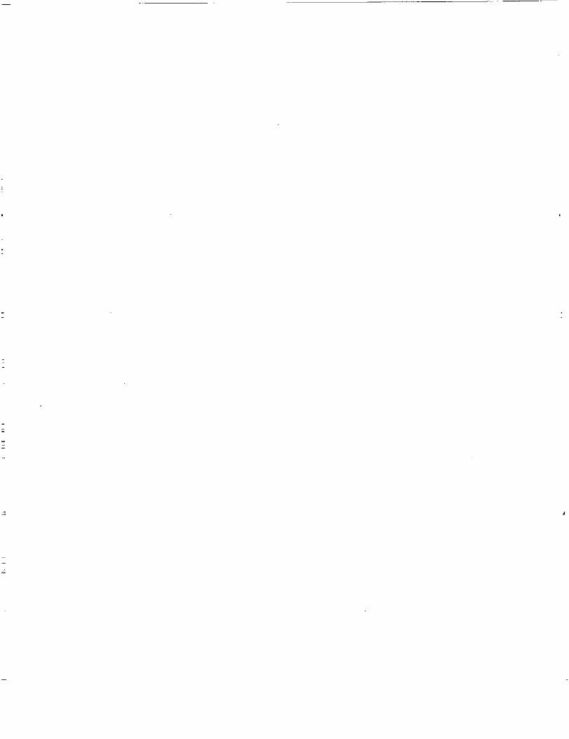
LASEPS is the combinationof two EPS breadboardswhich haveexisted at MSFC for sometime.Thesetwo breadboardsare-theautonomouslymanagedpowersystem(AMPS) breadboardandthespacestationmodulepowermanagementanddistribution(SSM/PMAD)breadboard.Figure2 showstheconfiguration of the two breadboardswhen they arehooked together.The two systemshave beeninterfacedwith theuseof two programmablepowerprocessors(p3,s).
AMPS
_[_ 168 Cell,-- 189 Ah
Vented
"[ NiCd Bat.
24kW
Load
Center
Lu_wgmmmw_u_mmDmmmm_n
120 + .5% Vdc
120 + .5% Vdc
Figure 2. Present configuration of LASEPS.
SSMA
PMAD
TEST
BED
A. Autonomously Managed Power System
In 1978, TRW received a study contract from NASA/MSFC to study the best power system for a
large orbital satellite, platform, or space station, projecting 1985-1986 technology use and a start ofmission in 1988. "This task focuses upon developing the methodology for achieving minimum life cycle
costs for a 250 kilowatt (kW) electrical power system in low Earth orbit including the interactions with
other subsystems, for example, thermal control, orbital altitude maintenance, and shuttle transporta-
tion. ''23 As part of this study, a reference design was to be provided for the proposed EPS, as well as, for
a testbed to be used for testing the conceptual designs.
The 250 kW power system design called for seventeen 16.7 kW channels to support 250 kW of
payload and 25 kW of housekeeping power for a total of 275 kW.
Each channel consists of one primary power bus and is electrically isolated from
the other channels (no tie connections), but all channels utilize a common power return
path. These isolated power channels are integrated into a cohesive operating utility by the
electrical power management subsystem (PMS). 23
The PMS which is referred to here is a set of control computers for the EPS. The PMS would then
communicate with an overall spacecraft computer to determine what interactions are needed between the
PMS and the other subsystems.
9

Out of this powersystemstudy, a proofof conceptbreadboardwasbuilt; this breadboardwascalledAMPS. Theoriginal conceptfor AMPS wasto havethreecompletepowerchannels(solar arrayandbattery)andtwo full 16.7kW loadcenters.Becauseof budgetconstraints,only one powerchannelandone24kW loadcenterweredeliveredto MSFC.A diagramof AMPS is givenin figure 3.
P_R
GENER-
AT_m
ENERGYSTORAGE LOAD CENTER
POWER
SOURCE
LOAD
'n_M_L
Figure 3. Autonomously managed power system.
AMPS is a 250 V system. The power channel consists of a 75 kW solar array simulator (SAS)
and a 168 cell, 189 Ah Ni-Cd battery. The solar array current and the battery charging and discharging
tasks are handled by an embedded computer called the power source controller (PSC), which is part of
the PMS. From this power channel, three buses are presently being simulated by dividing the outputs of
the battery and the SAS through three circuit breakers, one for each channel.
There is one 24 kW load center which has 10 remote power controller (RPC) simulators. An
RPC simulator, in this case, is a remote controllable switch which can protect against an overcurrent
condition in the load. Nine out of the ten RPC simulators can place its load on to one of two buses, the
tenth RPC simulator can place its load on any one of the three buses. There are three 1 kW RPC's, three
2 kW RPC's, three 4 kW RPC's, and one 3 kW RPC. The loads are controlled by a computer called the
load center controller (LCC), the second part of the PMS.
Above the LCC and PSC is the subsystem controller called the electrical power system controller
(EPSC). The EPSC's job is to oversee the whole electrical power subsystem and to communicate with
the overall spacecraft controller. In AMPS, as it is presently configured, the EPSC takes the information
from the LCC and runs a load balancing program on these data to try to balance the loads on the three
buses, and sends down these data to the LCC. The EPSC looks at the system data from the PSC andhandles the alarm conditions which occur.
10
A Sun4/330is thehostor overallsystemcomputer.Displayshavebeencreatedon the Sun4/330to displayall thesystemdatausingPrecisionVisuals' DI-3000graphicsdisplaypackage.
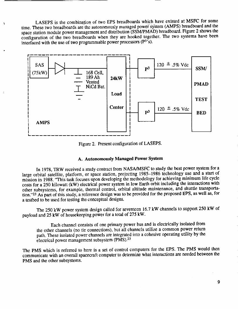
B. Programmable Power Processor (p3)
The p3 project was started in the late 70's for the 25 kW power module program. The 25 kW
power module program was also known as the power expansion package (PEP). This program was to
provide the orbiter with 25 kW of power for experiments and 2 kW of power for housekeeping power.
The power was to be generated by using high voltage batteries and solar arrays, p3's were to act as the
battery charger and output regulator for the system. 24
The task of two identical regulators performing different functions is satisfied by
microprocessor control. Experience with large space power systems, such as Skylab,
indicates a need for greater flexibility in EPS management. Microprocessor-controlled
regulators and chargers provide this capability. 24
The power system configuration is modularized from the power source to the
output busses (fig. 4). A specific portion of the solar array is dedicated to one
charger/battery/regulator system or Power Processing Group (PPG). The charger in each
PPG will process all of the power from its solar array section, using all power not
required by the bus regulator to charge the battery. When the bus power requirement
exceeds available solar array power, the charger will deliver the maximum available solar
array power and the battery will make up the balance. The power voltage levels and
regulator design were chosen in anticipation of future large space power systems using
higher voltage distribution networks. Evaluation of requirements led to the decision to
specify operation over an input voltage range of 30 to 400 Vdc and an output voltage of
24 to 180 Vdc programmable. The output current is specified as 100 A maximum
programmable. The power stage of the p3 uses three 100 A, 500 V transistors in parallel
stages to meet these requirements, u
1 OF 12
I
i
IIIII
I12 OF 12
I_
1
_'Q _ t _j,
I I " .us=i "1
BAT ,I
' ._l
8AT
Figure 4. EPS configuration. 24
BUS I
11

C. Space Station Module Power Management and Distribution
When MSFC first contracted for the SSM/PMAD breadboard--at the beginning of the space
station program--the breadboard was to be built in the space station configuration. Of course at the
beginning of the space station program, the station and the SSM/PMAD breadboard were to run off of
250 V, at 20 kHz. Provisions were placed in the contract for the breadboard to be switched to dc if the
space station was switched to dc, so when the modules were switched to dc so was the SSM/PMADbreadboard.
NASA's plans at the beginning of the space station program were to have the EPS automated.
The SSM/PMAD breadboard was built to test the space station module EPS hardware characteristics, as
well as to develop and test the automation software, using space station project money and advanced
development money. 26 As a result of all the changes in the space station program, eventually it became
counter productive for the SSM/PMAD breadboard to keep up with all the changes in the space station
program. The costs of continually changing the hardware and the constant interruptions to the power
system automation work which was being done on the breadboard became prohibitive. The removal of
most of the sensors and data processing equipment from the space station baseline configuration has
placed the SSM/PMAD breadboard farther into the advanced development arena.
Since the SSM/PMAD breadboard has become an automation testbed, the implementation of its
product is, at the present, aimed at ground-based operations in the mission operations center. The
mission operations people, who have been contacted about the use of expert systems type automation in
the space station, have expressed the opinion that it would be I0 to 15 years after launch and proven use
of the systems on the ground before any expert systems automation would be placed in flight on the
space station. 26 Figure 5 is a diagram of the SSM/PMAD breadboard. This diagram shows both thepower system hardware, the computers which control the power system hardware, and the higher level
computer and its software.
The power system architecture of the SSM/PMAD breadboard consists of two power buses. Each
power bus is controlled by a 15 kW remote bus isolator (RBI). The RBI's are zero current switching
devices, meaning that they are not built to be turned off or on under load. The use of an RBI is strictly to
isolate the breadboard bus from the power source and not to trip under fault conditions.
Below each RBI, there are a number of 3 kW RPC's. The RBI, some voltage and current sensors,
and the 3 kW RPC's combine to make up the power distribution control unit (PDCU). The maximum
number of RPC's in each PDCU is five. There are two PDCU's, one for the port bus and one for the
starboard bus. Each PDCU RPC controls the power to the port or starboard portion of each load center.
In the present configuration, there are only three load centers (LC's), so only three of the possible five
3 kW RPC's in each PDCU are being used.
The control system within each PDCU consists of a lowest level processor (LLP) and the
switchgear interface cards (SIC) which are shown in figure 5. The LLP commands the switches in the
PDCU on or off as the schedule demands, monitors the voltage and current sensors in the PDCU,
monitors the condition of each RPC, and sends information back to the higher level computer when
requested or when a contingency occurs.
12

PodPod Bus
PDCU
• .....,:...:, ..:.,., <
KnovdedgeandNeoo_6onTool(K_T)
L u,,.I,,_,_= :1
L. ' UN,XW_t.. J rL_I,
-- -- J PowerDataBus Bhemet
I Lead1 CoMer1
t
I (_ 16031704 1805190820
0 SensorVoltageCurrent
IIII 0_16031704 06 m m 04 06 O6L_ 1e_19 _ I le 17 111 19 20_Elh_.ernet .L .J
LoadCoMerDataBusRemote • RemotePower BusContr_[er Isokdor1 or3kW 15kW
PDCU - Power DistributionControl Unit
SIC - SwltchgearInterface ControllerLLP - LowestLevel Processor
Figure 5. Space station module power management and distribution breadboard.
Each load center consists of RPC's powered from the port bus and RPC's powered from the
starboard bus, with a voltage sensor and a current sensor located at the input to the load center of theport and the starboard buses. The RPC's in the load centers are each rated at 1 kW. In each load centerthere are five possible 1 kW switches.
There is an LLP and two SIC's per load center. The LLP has the same functionality as in thePDCU, except in the load center the level of requested current is monitored, and, if this level is exceeded
the load is removed or as the schedule terms it, the load is "shed." The LLP also has the capability toturn on a redundant load when the primary fails, as long as the redundant load is within the same loadcenter. The SIC is a switch interface controller which interfaces the RPC's to the LLP. There is one SICper bus in each load center and PDCU.
The 3 kW RPC's and the 1 kW RPC's have common features. These features are given in figure6. The RPC will trip under five conditions'
1. "Under voltage" (approximately 60 V)
2. "Fast Trip" (current limit is reached and maintained for 15 ms)
13

Figure6. 120Vdccurrentlimiting RPC.
3. "Over current" Trip (currentexceedsthe set trigger point the RPC will trip after the I2trelationshipis met)
4. "Over temperature"(RPCwill trip if aFETtemperatureexceedsthereferencetemperature)
5. Currentlimit failure ( theRPCwill trip at 400percentof its ratedcurrentif thecurrentlimitfails).
The RPCreportsthe reasonfor its trip to theLLP which forwardsthe information to the upperlevelcomputerfor fault diagnosisandreconfigurationof thepowersystem.
The tall white box in thecenterof figure 5 representsthepowersystemcomputeror the"higherlevel computer."Thecomputerwhich is fulfilling this functionat thepresenttime is a Solbourne5/500.This computer is a multitasking machine running the Sun operating system (OS). The knowledgemanagementand design(KNOMAD) environmentenablesvarioussoftwaresystemsto cooperate.Thefunctionsrunning within KNOMAD includethe front end schedulerthat takesthe main scheduleandbreaksthat downinto 15 rain segmentsto control thepowerhardware(front endload enablescheduler(FELES)),a loadpriority manager(loadprioritization list managementsystem(LPLMS)), thecollectionof planningandnegotiatingtoolsinsideKNOMAD (knowledgeandnegotiationtool (KANT)), thefaultrecoveryandmanagementexpertsystem(FRAMES),andthe user'sinterface.MAESTRO is anexpertsystemschedulerwhich is a productof Martin Marietta,Corp.,soit runsasits own process--notbeingsupervisedby KNOMAD, but interfacingto KNOMAD.
14

D. Fault Device
1. Proposed Fault Injection Device. The original concept for the fault injection device was to
use a computer to inject the faults into the power system. There are several advantages and
disadvantages to computer fault injection.
Some of the advantages of using a computer to do the fault injection included •
a. Improved safety
b. Computer timed fault injection.
Safety would be improved by not having exposed power terminals available for a person to come incontact with. The faults would be injected using relays. The timing of two simultaneous faults could be
computer-controlled to be within milliseconds of each other. Faults could be timed to occur in a cascade
from the lowest level upward with precision.
However, computer-controlled fault injection also has its disadvantages. Some of the
disadvantages include •
a. The appearance of one computer telling the other control computers what the faultis and where it is
b. The price and size of the relays needed to induce even the smallest faults into a
120 to 250 Vdc system
c. The time involved in programming the computer to control the devices.
The Electrical Power Division's management was concerned that there would be an appearance of just
"playing computer games" with one computer telling the control computer where the fault was and then
the control computer coming up with the correct diagnosis. With immerging technologies in power
systems control involved in this testing, the appearance of this type of "game playing" needs to beavoided.
Another concern of the principal investigators' (PI's) was the expense and limiting factors of the
number of relays which were needed to create the type faults which were discussed above and theamount of time which was needed to install them and then program the computer to inject the faults.
Also, the amount of work and time needed to move the faults from one location to another was a big
concern. In the end, a more flexible and simple method was used to inject the faults.
2. Existing Fault Device. In order to be able to install the faults into the LASEPS breadboard,wires were run from the breadboard into the fault device. This fault device contains fourteen 60 A knife
switches and twenty 20 A switches for a total of 34 switches on the fault panel. Below the assembly
which holds the switches are terminal strips where the possible fault locations are wired. There is also an
annunciator panel, shown in figure 7, which indicates where power is in the breadboard and also where
there are faults which have been injected into the system. The annunciator panel represents the final
configuration of LASEPS with two independent source channels. Figure 8 shows an example of how the
wires are run into the fault device from the SSM/PMAD portion of the LASEPS breadboard. Of course,
any of the wires which are shown going into the fault device can be faulted.
15

i 1¢:1:_1 L_ L_
." :1 :J _J=J" J"i,J-J.t-l- ,I -tt, f, i. • • i,,,, I: :11:L_,, _II
11 _T - . irr_ialio
}_ Jl oI=l= I JJoJJJ
,, _ _II11II
............................................... JL ....................................................
Figure 7. LASEPS annunciator panel.
FFA'0_"_-JE_'TiON DEVICE
.1/i' PDCU
/
/
/
/
LOAD CENTER
• i
LOADi i L°AD
LOAD
,, ILoAD_,Figure 8. Example of how the faults are wired into the fault device.
Ii i
J
16

IV. FAULTS
Since this fault study has been ongoing for over 3 years, the hardware fault results will be
presented chronologically by years. There are two reasons for presenting the data in this fashion. First
the data is related to the phase of LASEPS's construction. Second, these data have been organized in this
fashion for the year-end reports and the papers which have been written about this research.
A. First Year
The faults which occurred in the first year, are actual faults discovered in the AMPS breadboard
while reactivating it. These faults included:
• Communication faults
• Battery faults
• Load faults.
1. Communication Faults. The communication faults were not included in the power system
fault research. It is hoped that any problems with the communications between subsystem computers
will be discovered before the spacecraft leaves the ground. To date, communication problems have not
been mentioned as a problem with the electrical power systems flown. But with the complexity of power
systems and the increasing need to monitor them, this may be a problem in the future.
In fact, the fault in the communications system in the AMPS breadboard was one of the first
problems encountered. The fault had two causes, neither of which the systems in the breadboard couldcorrect without intervention. These problems were the physical disconnect of the Ethernet at one end of
an Ethernet cable. The other was an increase in traffic on the network so that the AMPS messages were
not getting to their destinations. The cable problem was fixed by reconnecting the pieces of the Ethernet
cable. The network traffic problem was fixed by creating a separate network for the AMPS breadboard.
The separate network was needed because the embedded computers in AMPS broadcast all
packets without checking to see if the packets are received. Also, it is considered bad form to send all
broadcast messages on an open network. The Ethemet in our test facility used to be isolated so that
"broadcast" messages were not a problem. But, since the systems in this room are now connected to theInternet, it became a problem for the embedded computers in AMPS to broadcast all their messages anddata.
2. Battery_ Faults. The battery system consists of 168 battery cells which are monitored by the
PSC through a battery cell scanner. There are 14 cell scanner boards that each read 16 measurements: 12
cell voltages, the voltage of the first 6 cells, the voltage of the second 6 cells, a ground measurement,
and the board's voltage reference. The battery is wired so that each set of 12 cells is wired to 1 scannerboard. There is only one wire coming from each cell. The voltages are read using the wire off the
previous cell, and the wire off the cell being read to get a differential reading. If one wire is broken, thatwire affects that cell reading, as well as, the next cell reading. The six cell readings are taken using anextra wire between the sixth and seventh cells which is used as a reference for each six cell
measurement.
17

No actual physical battery faults wereencounteredin the first year.What battery faults wereencounteredwere sensorfaults and brokenwires. A bad board in the battery cell scannerresultedinunusuallyhigh readingsof its 12cells, andthebrokenwiresproducedanomalousreadingstoo high ortoo low. Both problemsmadetheinitial chargingroutineof thePSCtrip to trickle chargealmostimme-diately.This meansthatwith thepresentprogramthebattery,if faultedin this manner,could beunder-charged,thusproducingotherbattery fault symptomsasdiscussedin thebatterysectionof this paper.Thesefaultswerealsofaults thatthesystemcouldnotcorrecton its own.
Thesefaults were corrected,andthe batterycycling wasstartedcycling (cycling only duringworking hours,endingeachworking daywith afull charge).Oneotheradjustmentthat had to be madefor the systemto cycle at LEO was to adjustthebatterychargingcurrent to 1/2 Idischarg e 4- 5 tO fully
recharge the battery in 60 min.
Some time after the system started cycling, it was noticed that the voltage of the battery was still
being read even when the battery safety switches had been disabled. The battery voltage should not have
been readable with the battery safety switch disabled since the battery safety switch removes the return
path connection of the battery to the breadboard and the battery voltage sensor. A battery voltage dis-
crepancy of 7.5 V was noted between the voltage across the battery terminals and the voltage that the
computer system was reading. One of the power supply voltages which feeds the battery cell scanner is
7.5 V, so the battery cell scanner boards were removed one by one to see which one of them was causingthe false ground path. Apparently one of the board's isolation components failed, and this caused a
ground loop or multiple paths to ground. Once the board was removed, there was no damage to AMPS.
The danger was to the personnel working around the battery, assuming the battery was isolated from the
return path to the breadboard, and there was the danger to the equipment if another fault had occurred.
Of course there is always danger working around any battery, but especially one of this physical andelectrochemical size.
3. Load Faults. Load faults, according to the fault research, are the most common EPS faults
encountered. In AMPS, there are three sizes of RPC's: 4 kW, 2 kW, and 1 kW. The loads that can be
attached to each of these RPC's represent one-third (low), two-thirds (medium), and full (high) load.
Full load is created by paralleling the low and medium loads. The first fault encountered in the loadcenter was a hard short of RPC 1 (4 kW). The EPS was isolated from the fault by RPC 1 tripping
immediately. The AMPS computers continued to function normally since the fault had been isolated.
Several hours after RPC 1 tripped, both of the switches in RPC 4 (4 kW) tripped off. Within
minutes of RPC 4 tripping off, the current on RPC 7 (4 kW) went from approximately 24 A to approxi-
mately 15 A. The response of the breadboard in each overcurrent condition was to trip the appropriate
RPC. Upon further investigation, the following values of resistance were measured in the load bank:
Resistance (ohms)Low Medium
meas. theor, meas. theor.
RPC1 ,,_ 30 2.8 15RPC2 60.1 60 28.7 30RPC3 i 17.9 120 56.9 60RPC4 _ 30 14.17 15RPC5 59.59 60 28.49 30RPC6 115.3 120 56.9 60RPC7 29.38 30 35.05 15RPC8 59.3 60 28.47 30RPC9 I 18.0 120 56.9 60
18

As canbeseen,the low loadresistorsfor RPC1and4 areopened.RPC4 will now function onmediumload,but RPC l's medium load is a hard short. It is presumed that before the low load for RPC 4 open-
circuited it was shorted and that is why the RPC tripped, sating the system.
Apparently, the medium load setting of RPC 7 has had one of the broken leads from one of the
other loads to fall on it and weld the two resistors together, which changed its resistance and created a
soft fault. The meter on RPC 7 reads 6.4 A and the LCC reads no current from the medium setting of
RPC 7. The meter on the RPC reads the current on the high voltage side of the RPC, and the LCC reads
the current on the return leg for the RPC, so the current from the medium load of RPC 7 is probably
being seen on another RPC. This is true since RPC 4's meter reads 15.5 A and the LCC reads the current
as 22.3 A. The AMPS breadboard handles the loads using what the LCC sees, so it does not know, with
its present programming, that there is a soft short.
At the present time, this load bank has not been fixed and may not be since the purpose of this
study is to produce realistic faults in the LASEPS breadboard.
B. Second Year
1. Batteries. The battery which is in LASEPS is a flooded cell Ni-Cd aircraft battery of the type
used for starting aircraft engines. This battery was 7 years old at this stage of the fault investigation. A 7-
year-old Ni-Cd battery is normally at or near the end of its useful life. This battery started showing its
age during some LEO cycling. At the end of the second discharge cycle, the battery voltage was
approximately 172 V. For a 168 cell battery, 172 V is just barely above 1 V per cell. At that time,
everything else was put on hold, and the battery was put into reconditioning. Reconditioning consists of
completely discharging a Ni-Cd battery, then charging it up to its name plate capacity or slightly above
name plate capacity, and then completely discharging it again. A number of these cycles are performed,
then a final discharge is performed to determine the new battery capacity. The battery capacity is
determined by computing the number of ampere-hours the battery outputs before the first cell goes to
zero. The LASEPS battery was reconditioned, resulting in a new capacity of 120 Ah.
Several months after the battery had been reconditioned, the cell which had been the low cell
during the reconditioning was failing to hold its charge. There were two cells left over from the original
battery cell order, so one of these cells was activated and the low cell was replaced. The lower cell wasreplaced in hopes that the battery would recover to its previous battery capacity of 120 Ah from the
approximately 90 Ah that the battery was operating at when this cell failed.
While a few cycles were being run for the new cell, the cell which had been the next to the
lowest cell prior to replacing the other cell discharged to 0.9 V before any other cell in the battery wasbelow 1.2 V. The battery capacity was up to 100 Ah. It was decided to replace the cell that was so low
during this discharge with the second spare cell.
One of the personnel of NASMMSFC's Energy Sources Branch suggested that the only way to
know if this battery would still do the job was to run it and see. Because of this suggestion, the charge
and discharge cycles that were run on this battery from this point on changed from a discharge at 30 A
until the first cell goes below 1 V, then drop the discharge rate to 15 A until the f'trst cell goes to 0 V, to
a straight discharge at 30 A until the fh'st cell goes to 0 V, This discharge rate is comparable to running
the SSM/PMAD through the p3's from AMPS.
19

Severalreconditioningcycleswererun on thisbattery,andthefinal capacitywasbackup to 111Ah. As wasmentionedin theresultsof thestudyportionof this document,end-of-life failure hasbeenthecauseof severalsatellite failureseither prior to their plannedend-of-life or possiblyfar beyondthesatellite'splannedlife, theend-of-life failureof thebatteryhasultimatelybeentheendof mostsatellites.In all fairness to this battery, it should be mentioned that this battery was not designed to cycle in LEO
type cycles. The manufacturer said to try LEO cycles, but the electrolyte might have to be emptied andthe cells reactivated if it did not work. However, a failure analysis of the two failed cells showed the
cadmium plates were falling apart, and the nickel electrodes were unwilling to accept charge, so these
two cells, at least, could not have benefitted from reactivation.
2. Solar Array Simulator. In the papers written about power system faults, 27 28 some of the
faults were labeled as probably too dangerous to attempt. One of these faults was the shorting of the
SAS output diode. As it turns out, this output diode is formed from three 1,000 V, 275 A diodes in
parallel. One of them shorted in the course of our battery cycling. There are many safeguards in the
AMPS system to isolate the battery or the three power channels in the load center from the SAS or eachother, but the only device used to isolate the SAS from the system is the SAS output diode (three in
parallel). Therefore, when the diode shorted, the battery had to be disconnected until the SAS could be
physically removed from the circuit before two 25 ohm, 100 W resistors inside the SAS were burnedout. These diodes are used in the input capacitor's soft start circuit, so they are not normally in the cir-
cuit when the SAS is on. Even though these resistors were glowing red hot, they were still good and well
within their 5 percent tolerance level. The wires feeding them, on the other hand, were only 18 or 20
gauge wire so they had to be replaced.
There could be several reasons why the output diode could short. The first is obviously age, since
it was a commercial part which was put into service in 1985. However, during the process of cycling and
reconditioning the battery, the 200 A fuse in the ground leg of the battery has been blown at least six or
eight times. The battery fuse blows when the SAS is on, with the SAS voltage above that of the battery
voltage, and the battery is attached. There is also a flaw in the battery charging software, which has notbeen corrected as yet, which causes current spikes on the system. The PSC current control routine,
which is a continuously running process, does not take into account that the battery is discharging and
tries to adjust the SAS's output current to the charging level. Therefore, when the "spacecraft" goes back
into "sunlight," the SAS's output current has been driven to full scale. The current meter on the SAS
pegs above 250 A. This implies that the output diodes in the SAS are possibly being stressed by the SASitself, as well as the battery, when the SAS is turned down or turned off for the battery to be discharged.
The SAS failed a second time. This time the battery was undergoing a slow charge (1 A for 192
hours) when one of the seven control channels of the SAS failed. When a failure of this type occurs, the
output voltage of the SAS goes to maximum. The maximum output voltage for the SAS-5 is 450 V.
When the voltage went so high, apparently there was a large enough current spike to blow the 200 A
fuse on the ground side of the battery, so the battery was protected. The suspected cause of the failure,
aside from the age of the SAS, is stress on the control components by using them in so unloaded a con-
dition for so long. Sometimes very light loads can be as stressful as very heavy loads to components.The solution for a too lightly loaded SAS during a slow charging cycle of the battery is to always have
more load on the system than just the battery.
3. Programmable Power Processor. The Pa's were designed and built in the late 1970's and
early 1980's. Their first use was in a high voltage battery test. Therefore, there were two p3's which
were designed and built for use in this type test. The P3's had to be checked out and programmed to
output 123 V nominally for use in LASEPS, but aside from that, they had the correct input and output
20

capacitorbanksto handlethehigh voltage.The PS'sweredesignedto takean input of up to 400 V and
regulate it to its set output voltage with a current limit of 100 A.
Since the p3's can regulate AMPS output voltage of 250 V down to the 120 V that theSSM/PMAD needs, phase I of the LASEPS breadboard can be considered complete and operational.
However, until the voltage level of AMPS can be dropped down closer to the SSM/PMAD level, a
device to limit the voltage that can get to the SSM/PMAD needs to be considered. Since the p3's are not
isolated, it is possible for the p3 to fail in such a way that the input voltage will be seen at the outputs. If
this occurs, then it is probable that every switch in the SSM/PMAD breadboard that is off will break.
The reason that the RPC's that are "off" may break is because there are some current limiting
diodes in the output circuit that can not handle this high level of voltage. The field effect transistors
(FET's) are 400 V devices, therefore, if the switches are on, the FET's will be able to handle the 250 V.
As will be seen later, these diodes can not handle the spike voltages being impressed on them by the
fault testing.
The fault mechanism which is described here for the p3 is similar in nature to the fault
mechanism which was described for the SAS. The device which would be necessary to limit the voltage
out of the p3 would probably be more expensive than replacing the FET's which were off in theSSM/PMAD breadboard, so no further investigation into a device of this kind has been done. This type
of failure mode in space probably is not acceptable, but, for ground-based test systems, the risk is
acceptable.
4. Space Station Module Power Management And Distribution. The major portion of the faults
which were injected in the second year of this study were placed in the SSM/PMAD portion of theLASEPS breadboard. These faults were placed in the SSM/PMAD breadboard either using the LASEPS
configuration or the external power supplies which were delivered with the SSM/PMAD breadboard.
There is no noticeable difference in the data taken using LASEPS compared to that taken when using the
external power supplies. The data taken using LASEPS or the power supplies looked so alike that there
was no need to mark the data as to which configuration the data were taken under. There are two
reasons that the data appear the same using either configuration. The reasons are similar in nature: Fu'st
the supply to the SSM/PMAD breadboard either way is through a dc to dc converter, and second, the
RPC's are current limiting so the load can only see a maximum current for a specific amount of time.
The main categories of faults which were injected into the breadboard are:
• Direct shorts to ground
• I2t trips.
These faults will be treated separately, as well as handling several faults which also occurred within the
SSM/PMAD portion of the breadboard.
It is important to understand that the responses of the software, which are reported within this
paper, will improve with future deliveries of the SSM/PMAD software. Part of the purpose for doing this
fault testing is to improve the responses of this automated control system. The other reasons include
characterizing the present hardware and characterizing the response of similar power buses for future
spacecraft.
21

In the SSM/PMAD breadboard,the direct shortsto groundandtheI2t trips were placedbeloweachPDCU switch, aswell asbeloweachload centerswitch.This wasdonefor completenessandtomakesurethe softwarewould respondproperly throughoutthe system.Thesefaults were not placedbelow theRBI's. SinceanRBI hasnoprotectioncapability,to placeafault below the RBI would just be
testing the p3,s or the external power supply's ability to current limit.
The configuration of the switches in the fault injection device turned out to be perfect for the
testing of the SSM/PMAD breadboard, since there were a total of 34 RPC's in the breadboard to be
tested when the testing started,
a. Direct Shorts to Ground. The PDCU and load center switches are both current limiting so
that a direct short to ground fault could be applied without having a current limiting resistor in line withit. When the direct short to ground fault was applied, in every case the switch tripped in under 15 ms
(fig. 9(B)). The software marked the switch with FT, for "fast trip," and a diagnosis like this was made:
Most Likely:
Low impedance short in the cable below "switch number," switch output "switch
number," or switch input of a lower switch.
Less Likely:Current sensor in switch reading high.
The actual switch designation is placed where the words "switch number" are.
More interesting than the reactions of the hardware and the software is the reaction of the bus as
shown in figure 9(A). This picture shows the first 95/.ts of a PDCU switch (3 kW rating). Figure 9(C) is
a representation of where the currents and voltages on the graph are measured.
b. Shorted RPC. While testing the direct short to ground faults, it was noticed that one of the1 kW switches was shorted. The short of this 1 kW RPC implies that whenever voltage was supplied to
the switch, current was drawn by the switch. This current was drawn even when the interface showed
this switch open. The software did not recognize this fault since the data which were going to the screen
were not given to the fault diagnosis program. The data needed to make this diagnosis can be sent to the
proper program, and this change was made in the next release of the software.
In the next release of software, FRAMES can diagnose a shorted switch in the 1 kW RPC's,
since only there does a shorted switch pull power when it is supposed to be off. Under normalcircumstances, a shorted RBI or 3 kW RPC in a PDCU would not have any load below it to pull current
so these conditions would be harder to diagnose.
To see how the system would react, a direct short to ground was placed below the shorted 1 kW
switch. When the fault was placed below the 1 kW RPC, the 3 kW PDCU switch was placed into current
limit and the PDCU tripped. The diagnosis was the same as for the direct short to ground in the releaseof software this was tested with.
c. I2t Fault. There were several valuable pieces of information about the hardware and software
which were gathered by testing the I2t function of the RPCs. One interesting occurrence happened while
testing the PDCU's, and the other piece of information was gained while testing the 1 kW RPC's in theload centers.
22

Bus Volt20 V/Fault Volt
Load Cur:10 A / div
Fault
": , .-., .... • .... • .... w .... , .... • .... • .... ,-.-
Blue
- 5_ - 10 _s/div 95_s
(A) Initial transient.
Red
Bus Volt.
20V/div. :
Fault Volt.
Load Cur.'
10 A / div
Fault Cur.,;
Redi i
(p) Purple
(b) Blue
P
i i i, I --
-1 ms 2 mA div..
(B) Direct short to ground trip.
Blue
___..y
_.,_____/LOAD CENTEt
i i---..-.--
19 ms
(c)
Figure 9. 3 kW RPC direct short to ground.
F"
(1) Power Distribution Control Unit. When the PDCU's were tested for the I2t function of the
RPC, they were tested using a 4 ohm short to ground and under various loading conditions. These load
conditions included 10 A of load on the PDCU (fig. 10), the lightest load the load center could provideon the PDCU, and no load below the PDCU switch from the load center. The tests were run in manual or
maintenance mode, then while the system was in autonomous mode. When in autonomous mode, the
load on the load center depends on what part of the schedule is being run and which load center the
PDCU switch is controlling.
The fault resistance to be used in forming the I2t faults below the PDCU's was to be 4 ohms. The
actual value of the 4 ohm resistor turned out to be about 4.14 ohms. The 4 ohm resistor was just on the
edge of triggering the I2t timer with a value of exactly 4 ohms. As a result of this slightly too high
resistance value, two things happened. First, if none of the loads are on in the load center, the switch
23

Bus Vol20V/div. :
Fault Volt
Load Cur.'
10 A/di_.
Fault Cur
-13 p.s 10 Ixs / div.
(A) Initial transient.
. Red
Purple _
87/,tS.
Bus Volt20 V/div._Fault Volt
Load Cur.
I0 A Idiv,
Fault Cur_
Blue
(p) Purple:::::::::::::::::::::::: ;;_
g
-260 ms 200 ms / div. 1.74 s
(B) 4 ohm short to ground trip.
Red
-- il <.v
LOAD CENTEI
Figure 10. 3 kW RPC 4 ohm short to ground.
i k-! ?
jdoes not trip and the system does not shed (turn off switches which are pulling too much power) a
switch at the PDCU level. This is a problem since the system will allow a fault of this type to remain on
the switch forever or until some load is turned on below it to reach the I2t trigger point. The other thing
which came out of applying this fault shows up in autonomous mode. With a schedule running in
autonomous mode, when the 4.14 ohm fault is placed in the system the switch trips, in what is called in
the software an "over current" trip, and all the switches below the PDCU switch are tripped on
"under voltage." The first thing the software does is turn off all the switches which tripped, then it goes
in and turns on the PDCU switch to see if it trips again. Because the switch is now unloaded, it does not
trip again. The software then comes back with the following diagnosis:
24

"PDCU switchname"Over-Currenttripped.The fault hasnot beenrepeated(andthereforenot found).Thefollowing switchescannotbetested:
"load centerswitchname""load centerswitchname""load centerswitchname""load centerswitchname"
PossibleCauses:Most Likely:A transientshort somewherebelow "PDCU switch name."A short below one of theswitchesthat werenot testable.
Of course, the "PDCU switch name" and "load center switch name" indicators are replacedby theappropriateswitchdesignations.After thisdiagnosisis made,theswitchis taken"out of service."
Two changesto the softwarehavecomeout of this testing.The first involves the fact that theswitchesbelow thePDCU shouldbe tested.In this case,theswitchesbelow thePDCU werenot tested.Of courseif theywere,thesoftwarewouldhavecometo theconclusionthatthefault wasbelow thefirstswitch thatwas turnedon,which wouldstill beawrongdiagnosis.Thefirst switchwould thenbetakenoff line, andthePDCU would thenberescheduledto comeon.ThePDCUswitchandtheloadsbelow itwould beturnedbackon,andthePDCU switchwouldagaintrip. Thiscyclewould continueuntil all theswitchesbelow thePDCU switchweredeclared"out of service,"andthen thePDCU would bemarkedasfaulty, aswell. Clearly this isnot anadequatesolutionby itself.
The secondchangemadeto the software involveschecking to seeif current is being drawnbelow aswitch whereit is knownthatthereshouldbenocurrentbeingdrawn.If currentis beingdrawnbelow theswitchwherenocurrentshouldbe,thefirst thing thatwill becheckedis to seewhetheranyofthe switchesbelow the onepulling currentis alsopulling current.If thereis currentbeingdrawnby aswitch below the PDCU, thetwo currentswill becompared,and,if theymatch,the solution is thattheswitch which is pulling currentis shortedclosed.If thetwo currentsdonot match,theconclusionthatthereis alsoa soft shortbelow thePDCU,aswell, will alsobemade.Of course,if no switch is drawingcurrentduring thefirst test,theconclusionwill bedrawnthatthereis a soft fault below thetestedswitch.
Becauseof thephilosophyof operationwhichwasadopted,theproblemwith thefault below thePDCU switch in maintenancemoderemains.ThedecisionwasmadethatthePDCU switcheswouldnotbe turnedoff by thesoftwarefor a soft fault condition.In otherwords,if the switchdoesnot trip itselftheswitchwill notbe turnedoff, atleastin manualmode.
(2) Load Center.The I2t fault which wasput into the 1 kW RPC's in the load centerswasapproximately14ohms(fig. 11).This fault, unlike theoneinjectedon thePDCU's, alwaystrippedtheloadcenterRPC's on "over current."Themainthing which waslearnedfrom applyingthesefaults wasthatthereis aracebetweenthehardwareandsoftwareasto whichcatchesthesefaults.
When the SSM/PMAD breadboardwas first designed,the LLP's were Motorola MVME107,68010board level processors,communicatingthrougha VME 10with the expert systems.Now theLLP's are 80386DX, 20 MHz basedPC's which communicateacrossthe Ethernetwith the expertsystems.
25

BusVolt _20 V / div.:
Fault Volt. b. _ (b) Bluc,¢
Load Cur P_e ,,._
1A/div.[_
Faultcui 5A/div. L
-13 laS 10 _s / div. ' _7 VS.
(A) Initial transient.
Bus Volt.
2_ V / div.: _Fault Volt Blue
Load Cur. (p) Purple1 A /div'.
Fault Cur,
5A/div_
-260 ms 2130 rn
(B)
P
Idiv. 1.74
14 ohm short to ground trip.
Red
Purple(___,____.....,_VV_
"T" 14
Green
OAD CENTEI_
Figure 11. 1 kW RPC 14 ohm short to ground,
The 386 machines monitor the status of the RPC's in the load center fast enough that the slow I2t
fault applied would sometimes be caught by the LLP before the I2t timer would time out. The old LLP'swere so slow that it was assumed that the RPC would always trip first. These races were a result of not
taking into account the extra speed of the new LLP's or failing to rewrite this portion of the code when
the change was made.
The main problem with the races between the RPC hardware and the LLP's to detect the I2tfaults is that the two situations are not handled the same way by the system software. When the RPC
trips for an I2t or "over current trip," the switch is taken "out of service" and a diagnosis like the
following is given:
26

Most Likely:High impedanceshort in the cable, below "load center switch," switch output "loadcenterswitch," or switch inputof a lowerswitch.LessLikely:Currentsensorin switchreadinghigh.
Although thereis no switch which is known to bebelow theloadcenterRPC's,theremay besomeintheloads.A switchof this typewould bepartof the load.
The RPCwhich is shedby the softwaregetshandleddifferently than the RPCwhich trips on"overcurrent."As thesystemperformedat thetimeof this testing,a loadwhichwasshedfor pulling toomuchcurrentis scheduledto beturnedbackon 5 min later for thesamepowerrequirementsit hadjustviolated.In mostcaseswherethis wasdonefor oneof the loadswhichhadan I2t fault appliedto it, theI2t function of theRPCeventuallydid trip andthecycleof turningon, beingshed,andreschedulingdidstop.However,whentheload on theRPCwasaround2 A, the LLP alwayscaughtthe "over current"beforetheRPCtripped.
The responseto an LLP discoveredovercurrentwaschanged.The softwarewill now put theRPC"out of service" with a diagnosiswhich statesthat the switch is pulling too much current.Thismakestheexperimentevaluateits currentdrawanddecideif thepowerallocationaskedfor is too low orif there is something wrong with the experiment. In either case, the experiment must ask to berescheduled.
d. Internal Failure of the RPC. An internal failure within an RPC causes an "over current"
response in the software. There is a constant current diode in the circuitry which is rated from themanufacturer at 100 V, 1 mA. Before these devices were placed in the circuit, they were test selected for
a minimum voltage of 150 V. However, with the faults being placed in the system and the voltage and
current spikes which have been inserted into the system, 150 Vdc does not seem to be enough margin.One of the 1 kW RPC's failed with the constant current diode blown while in a steady-state on situation
during fault testing of another load center. The RPC tripped on an "over current" fault. Apparently, thesediodes have been over-stressed with all the faults which have been inserted into the system.
The solution for this problem is to replace the single diode and resistor, which are in the circuitnow, with two of these diodes in parallel and two higher valued resistors. This is being done when the
RPC boards are removed from the system for any reason, but the RPC's are not being removed just to
add this modification.
e. Transients. The definition of a "transient" fault which is being used is a fault which does not
last long enough for the system to detect it. Most of the transients, which were seen in this part of the
testing, were the PDCU 4.14 ohm I2t faults. When the autonomous testing of these faults was done, onlyone or two of these faults could be done at a time without bringing down the system in between. This
was caused by data being mishandled by the fault diagnosis program. A flag, which was set by the
"transient" fault, was not being reset after the switch was taken "out of service." This problem was fixedin the next software release.
5. Large Autonomous Spacecraft Electrical Power System. For some time, LASEPS was runonly as the SAS and/or battery running the SSM/PMAD breadboard or the AMPS load center, but not
together. A test was run to see how the computers in AMPS would react to the p3's and the SSM/PMAD
hanging on its buses as well as its own load center.
27

The PSCis theonly computerin AMPS thatseesthecurrenton the buses from the SSM/PMAD.The EPSC and the LCC do not see the current, therefore, AMPS acts as though the current from the
SSM/PMAD is not being drawn. The LCC probably does not have to know that the current is there, but
the EPSC needs to get the information from the PSC and take that current into account when trying tobalance the loads on the three channels (buses) in the AMPS load center.
Until some reprogramming of the AMPS computers can be done, the Pa's and the SSM/PMAD
breadboard are effectively "soft faults" in the AMPS breadboard, since AMPS does not react to their
presence. This presents one of the limitations of automated control in that the programmed system can
only react as programmed. New situations outside of the written software can not be handled with anycertainty of correctness. Of course, drastic changes in power system configurations, like the addition of
SSM/PMAD onto the AMPS bus structure, is not likely to occur in flight, but this illustrates why the
human must remain as one of the variables in the control loop.
C. Third Year
1. Creating Cascading Faults. After a brief review of the SSM/PMAD breadboard which has
been used in this fault testing, the background will be set to start the discussion into the lessons which
have been learned while testing cascading faults in the SSM/PMAD.
When testing of cascading faults first began by placing two faults in the breadboard
simultaneously, one on a 1 kW RPC and one on a 3 kW RPC, it was hard to decide whether FRAMES
was handling the fault scenario properly or not. FRAMES handled this situation as though these were
two separate faults on most occasions. The timing had to be perfect for FRAMES to see these two faults
as anything other than two separate events and therefore two separate faults.
Since, in reality, we did indeed have two separate faults, it became necessary to see if cascading
faults could be induced into the SSM/PMAD breadboard. Causing cascading faults in the SSM/PMAD
breadboard is more of a challenge than it may, at first, seem.
The RPC's in the SSM/PMAD breadboard have several advanced features, including current
limiting at 150 percent of their current rating. The RPC's can be tripped off under two current
conditions: "fast trip" and "over current" trip. The RPC "fast trips" when the RPC is placed in currentlimit for 15 ms. The "over current" trip can also be defined as an I2t fault. In an I2t or "over current"
fault, the RPC trips off after a progressively longer time the lower the current value on the RPC. Theminimum current value, which triggers the "over current" trip, is 120 percent of the RPC's current
rating. The RPC's also trip on "under voltage" when the voltage goes below 60 Vdc.
In addition to the hardware limits which have to be met to create cascading faults, when the
system is working with a schedule in autonomous mode, the LLP's know the correct value of currentdraw that each load below the 1 kW RPC's are scheduled to draw. This means that above the scheduled
value the LLP will "shed" any load which is above that value for two sweeps of the LLP data collectionroutine, this translates to between 800 ms to 1.2 s. The software is set up so that a "soft fault" on a 3 kW
RPC is not "shed," under the assumption that you want the 3 kW RPC's on unless something trips themoff.
28

A conjunctionof all of thevariablesabovemeansthattwo faultsarenecessaryto makethe3 kWRPCtrip whena 1kW RPCbelow it trips. Specifically,a"soft fault" below the3 kW switchbig enoughto get the 3 kW switchcloseenoughto its 120percent"over current" trip trigger point that when an"over current" fault is inducedin oneof the 1kW RPC'sbelowit, the3 kW RPCwill trip also.
Since,for critical loads,thepowersystemmustbe two fault tolerant,the abovecascadingfaultscenariohasto be studiedfor spacecraftpowersystems.It is alsotrue that not all power systemshaveprotectivedeviceswith enoughmarginin their protectivezonesto requiretwo faults to causecascadingfaults to happen.Effectively, the"soft fault" on the3 kW RPCis reducingthe 3kW RPC's"cascadingfault protectionmargin." Normally the"cascadingfault margin" is usedto coordinatefault propagationto try to insurethatthe lowestlevel fault deviceis usedto isolatethefault.
2. Faults Propagate. When the two faults were first placed in the breadboard to simulate a
cascading fault, FRAMES reacted differently depending on how the faults were placed into thebreadboard. Three representative cases were created:
1. Place an "over current" trip on a 3 kW RPC then 2 s later appiy a "fast trip" to a I kWRPC below the 3 kW RPC.
2. Place an "over current" on a 3 kW RPC at the same time or just after the 1 kW "fast
trip" is placed into the breadboard.
3. Place an "over current" trip on a 3 kW RPC and 5 s later place the "fast trip" on a1 kW switch below the 3 kW RPC.
In each of these cases the 3 kW fault is removed before FRAMES starts its diagnosis to simulate the
causal relationship between the 1 kW RPC fault and the 3 kW RPC trip.
a. 3 kW "Over Current" Then 1 kW "Fast Trip." In the first test case, where the 3 kW RPC is
placed into an "over current" condition before the 1 kW RPC is "fast tripped," both faults are registered
in FRAMES before the diagnosis process is begun. FRAMES first opens the 3 kW RPC and all the1 kW RPC's below this 3 kW RPC. Since the fault is removed from the 3 kW RPC, when FRAMES
recloses the 3 kW RPC to test it, the 3 kW RPC does not trip again. After the 3 kW RPC is tested
without tripping, further testing is done by reclosing the "testable" 1 kW RPC's below the 3 kW RPC.
The criteria for a 1 kW RPC to be "testable" is:
1. It must be currently scheduled ON
2. The fault condition must be "under voltage"
3. The switch must be "testable".1
1. Testable is an attribute assigned to a piece of powered equipment's mode of operation. The term "testable" switch refersto the ability to test this switch with the current load attached. This attribute prevents damage to a load that can not be turnedoff and on.
29
Thecriteria for anuntestabte1kW RPCis:
1. Switch is currentlycommandedON.
2. Theswitch is "not testable"or thefault typeis not"undervoltage."
All switcheswhich arenotcurrentlyscheduledto beturnedON areignored.
In the first test case, the "fast tripped" 1 kW RPC is placed into the "not testable" group.FRAMES tests the 3 kW RPC and the "testable" 1 kW RPC's and determines that there was a"transient"condition belowthe3 kW RPC.ThedecisionwasmadethatanRPCwhich tripsbecauseof a"transient"will be placed"out of service," sincetheability exists to askfor an"out of service"RPCtobe placedback "in service." So the 3 kW RPCis placed"out of service," and the 1 kW RPC's aremarkedas"unreachable,"sincethereis nopowerpathto supplythe 1kW RPC'spower.
Theintendedprocedureduringthetestingphaseis to wait for the 1kW RPCto be turnedon,andthen fault the 3 kW RPC again to recreatethe conditions of the first fault. FRAMES, in beingconservativeand not turningbackona knownfaultedRPCbelowanotherfaulted RPC,doesnot allowthe fault to be repeatedandfails to take advantageof knownknowledge.This is an exampleof faultswhich needmorethoughtandpossiblyanunrealisticfaultscenario.
The 3 kW "overcurrent" fault wasplacedfirst in this fault scenarioto insurethat the3 kW RPCwould trip alongwith the"fast trip" on the 1kW RPC."Fasttrips" weretheonly faultswired in thefaultdeviceat the time of this test for the 1kW RPC's. A more realistic fault would be two over currentfaults.This testcaseis not very realistic,but it wasusedto try to insurethat both faults wereregisteredbeforediagnosisbegan.
b. 3 kW "Over Current"/1 kW "FastTrip." In thesecondtest case,the "over current" on the3 kW RPC and the "fast trip" on the 1 kW RPC areapplied virtually simultaneously.In this case,FRAMES startsits diagnosiswhenthe"fast trip" is receivedfrom the 1kW RPC.FRAMES goesoutandaskstheLLP' s if theyarein aquiescentstateto give their datato FRAMES.Sincethisprocessonlylooksat theRPCstatusandnot atanyprocessingbeingdoneby theRPC,aquiescentstateis seenbytheLLP in the PDCU and data are returnedto FRAMES creating the original symptom set. After thecommandto open the 1 kW RPC is issued,moredataarerequested.It is at this time that the "overcurrent" of the 3 kW RPCis seenalongwith the"undervoltage" trips of the rest of the 1 kW RPC'sbelow this 3 kW RPC.WhenFRAMES seesthesedata,it concludesthatthe opencommandcausedthe"over current"and"undervoltage"trips.
Therearetwo errorshere.First, thereis atiming problembetweentheLLP's. Theseconderroristhe assumptionthat the openingof any RPCcould causeotherRPC's to "over current" and "undervoltage."
The timing problem is amplified in this examplebeyondthenormal timing problemsthat areseenin the SSM/PMAD breadboard.In this breadboard,the LLP's are not synchronizedso that theelaboratemethodstakenin thefirst exampleto makesurethetwo faults werereportedto FRAMES arenecessary.The sameis true here,but to a different extent. Here the LLP needsto check for moreinformationthanjust whetherthestatusof theRPC'sarein flux, it alsoneedsto checkfor currentlevelquiescent. ....
3O

The secondproblem, that of FRAMES assuming that the "over current" and "under voltage"faults are caused by the open command, is a problem of interpreting data. It has been suggested that all
new data which are received during a diagnosis have to be considered unrelated to the fault at hand. In
the case with unsynchronized computers, the data may or may not be related to the fault which is being
diagnosed. All new data should not be ignored or why should testing be done at all. However, in the case
where a higher level switch faults after diagnosis has begun, test should be redirected to the higher levelswitch before testing can continue on the present diagnosis. A switch cannot be tested when there is no
power available. If the higher level switch tests conclude that the higher level switch does not trip, the
testing of the present 1 kW RPC can continue.
Without the fault on the first 1 kW RPC causing something else to fail, it is not believed that the
3 kW RPC would continue to be "over currented" after the 1 kW RPC tripped off. So this situation is
unlikely unless the faults are two "over current" faults which time out at the same time and the data did
not get received by FRAMES at the proper time.
c. 3 kW "Over Current" Before 1 kW "Fast Trip." The third test case, the 3 kW RPC is "over
current" tripped about 5 s before the 1 kW RPC has a "fast trip" placed below it. The 3 kW RPC "over
current" trips and all the RPC's below it "under voltage." The LLP's present their initial data to
FRAMES and open the 3 kW RPC and all the 1 kW RPC's below it. When FRAMES tests the 3 kW
RPC, the 3 kW RPC does not trip again since the trip on the 3 kW RPC has been removed. With the
testing of the 3 kW RPC completed, FRAMES proceeds with the testing of the 1 kW RPC's. During this
testing, a 1 kW RPC "fast trips." Although the "fast trip" of the 1 kW RPC occurs during the testing ofthe 3 kW RPC, FRAMES assumes this fault is an unrelated fault and continues with the 3 kW diagnosis.
The diagnosis of the 3 kW RPC is completed and then the 1 kW RPC is diagnosed. This is the way the
present system has been configured, but this is a flaw in the diagnostic logic. It has not been proved thatthe fault of the 1 kW RPC is unrelated to the 3 kW RPC fault under these circumstances. Most engineers
would assume that there, at least, might be a relationship.
The 3 kW RPC is diagnosed with a transient fault, since the RPC did not retrip during testing.
The 1 kW RPC is then tested after the 3 kW RPC is placed "out of service," and the 1 kW RPC is made
unreachable by this fact. The diagnosis which is reached by FRAMES for the 1 kW RPC is that there isa "fast trip" below the 1 kW RPC. This is a correct answer but derived from erroneous data. Since the
3 kW RPC has been placed "out of service" when this 1 kW RPC is reclosed the 1 kW RPC faults on
"under voltage," but FRAMES interprets the data to mean that the RPC "fast tripped." It is true that theRPC retripped, but it did not "fast trip" the second time. FRAMES needs to just mark the 1 kW RPC as a
possible failure which it is unable to test.
d. Results of Actual Testing. Although the way the third fault test case is created makes it seem
unlikely, this test case is closest to the results which have been received in the actual insertion of
cascading faults into the breadboard, to date. What is simulated in the third test case and what happens in
the actual cascading faults is that the 3 kW RPC trips before the 1 kW RPC can isolate the cause of the
problem. This means that the trip coordination fails in this case.
The actual cascading faults which have been injected into the breadboard have all included the
placing of two faults into the breadboard: a soft fault below the 3 kW RPC and an "over current" faultbelow a 1 kW RPC below the same soft faulted, fully subscribed 3 kW RPC. This means that the 3 kW
RPC has scheduled loads on it close to its 3 kW rated value. As was stated above, in some systems
which do not have the "over current" protection margin SSM/PMAD has, the soft fault may not be
needed to cause cascaded faults. An RPC or other switch, which is failed closed and undetected, could
31

andhascausedthis kind of cascadedfault in our system by placing too much load on the 3 kW RPC.
The operations error of placing too much load on one RPC can also cause this type of fault. As it turns
out, the third test case was the most realistic test case in the testing conducted so far.
V. CONCLUSIONS
A. Fault Study
From the fault study, several conclusions can be made. The first has to be that there is no
repository for the accumulation of power system fault data. Even as this report is being written, theauthors have been informed about other historical power system faults which have occurred in space or
in the terrestrial utility industry. When power system faults happen, they have a tendency to be fixed and
forgotten, not well documented.
The second conclusion that can be reached is that, from a power utility aspect, the most common
power system fault is in the terminal end user's load. The load on the power system will tend to be more
complex and have more failure modes than the distribution system. For the most part, the power
transmission lines of a contained power system do not tend to short or breakdown without external
influences, like movement of loads in and out of the system or someone crashing a car into a power pole.
The power switching devices are more susceptible to failure than the transmission lines when external
influences are not present, because of the powe r switching devices' complexity. Power generation andstorage probably have as much complexity as the switching comp0iients or the loads, but are normally
monitored more fully than either the loads or the power switching devices, so any problems there are
normally anticipated.
B. Power System Testing
Although the power system which was studied was not a very generic one because of the
intelligent switches and the intelligent control computers, the power system control knowledge which
was embedded into the control computers was tested to see how accurately that knowledge has beencaptured in the software. For the software limitations and philosophies under which the breadboard
software was written, the system functions very well. Some of the things that are being referred to by theprevious statement include the assumptions in the software that the sensors and power hardware will not
fail, and the philosophy of operation that detailed data about the loads was not to be used. The detaileddata were not to be used since the power system overall operation was to be considered to run like a
terrestrial power system in which the utility company does not care where something is plugged in, it
only cares that the loads do not imbalance the terrestrial three-phase system.
During the time in which the power system was being tested, many bugs in the software codewere found and most of them fixed. One or two limitations of the software were found and documented.
Several holes in the control logic were found, most of them filled, but several have yet to be solved in asatisfactory manner. These holes are mainly in the areas where more human interaction will be needed
with the control systems to diagnose the problems. This interface still needs some defining before these
problems can be solved.
32

C. Cascading Faults
Cascading faults present a more complex fault scenario in automated EPS's than any other kind
of fault scenario, since the coordination of the data is key to the recognition of this type of fault.
Embedded in this problem of coordinating the data is also the problem of deciding whether witnessed
events are related or not. The assumptions which have been and are being used to write the SSM/PMAD
control systems are also key to how the data are interpreted.
One of the key problems which the diagnosis of cascading faults has run into is the lack of
synchronized data. A time stamp on the data could help some, but, if the data collection devices are not
synchronized, the time stamps might actually be detrimental instead of helpful.
The recognition of related events is another key part of diagnosing cascading faults. Some of the
key assumptions which have been made or suggested for the SSM/PMAD are contrary to being able to
conclude that two faults are related. Under some circumstances, the resulting information caused by the
three test cases used in the initial cascading fault simulations could represent possible cascading fault
scenarios. Any two faults which occur in a hierarchical line of switches should be investigated for the
possibility of being cascading faults. Any fault diagnosis system should not disregard new information
which is gathered during testing as unrelated data. If only the expected data are considered during
testing, then many diagnoses will be flawed.
Two of the basic assumptions which were incorporated into the FRAMES design were that the
sensors and switches would not break, and that they would always supply accurate data. The
SSM/PMAD software design has come a long way with its original assumptions, but, to be able to
extend its capabilities, the time has come to go beyond some of these initial assumptions and try to
expand the ideal assumptions into the world of non-ideal conditions.
33

REFERENCES
1. Gerson, Amy C. Reiss: "Spacecraft Electrical Power Systems Lessons Learned." 1988 IECEC,
vol. 3, pp. 785-788.
2. Stevens, John N., and Stillwell, R.P.: "Environmentally-Induced Discharges in Solar Arrays."
1989 IECEC, vol. 1, pp. 385-391.
3. Stevens John N., and Underwood, Carol S.: "Coupling of Environmentally Induced Discharge
Transients Into Space Power Distribution Systems." 1989 IECEC, vol. VI. pp. 2623-2630.
4. Kapustka, Robert E., NASA/MSFC, Electrical Power Branch.
5. Marvin, Dean C., Hwang, Warren C., Arnold, Graham S., and Hall, David F.: "Contamination
Induced Degradation of Solar Array Performance." 1988 IECEC, vol. III pp. 103-105.
6. Becker-Irvin, Craig: "Solar Cell Reverse Biasing and Power System Design." 1988 IECEC, vol.
III pp. 43-47.
7. Salim, A.A., Huraib, F.S., Khoshaim, B.H., Eugenio, N.N., Rao, N.R., and Imamura, M.S.:
"Performance Characteristics of the 350-kW Concentrator Photovoltaic Array Field." 1986
IECEC, vol. II pp. 1285-1291.
8. Schulze, Norman R.: "NASA Aerospace Battery System Program Initiation." 1987 IECEC, vol.
I, pp. 48-51.
9. Halpert, Gerald, and Rowlette, John J.: "The Battery Safety Handbook" Jet Propulsion
Laboratory, Electrochemical Power Group.
10. Hall, David K., NASA/MSFC, Electrical Power Branch.
11. Lurie, Charles, and Steen, Atle: "Reliability Modeling of High Voltage Batteries." 1982 IECEC,
vol. II, pp. 751-756.
12. Bush, John R., Jr., Jackson, Lorna G., and Lanier, John R., Jr.: "Hubble Space Telescope
Electrical Power System Simulation Breadboard." 1987 IECEC, vol. II, pp. 618-622.
13. Britting, Alfred O., Jr.: "Viking Lander NiCd Battery Special Reconditioning Sequences." 1982
IECEC, vol. II, pp. 731-735.
14. Badcock, C.C., Donley, S.W., Hwang, W.C., and Matsumoto, J.J.: "Results From Life Test in
Progress on Eagle-Picher Nickel Cadmium Cells." 1987 IECEC, vol. II, pp. 740-744.
15. Mesnard, G., Faber, J., and Kornelson, K.: "Flight Experience of the Solar Mesosphere Explorer
Satellite's Power System as Battery Capacity Declines." 1988 IECEC, vol. IN, pp. 789-792.
16. Porter, Greg: "Look Beyond Waveforms for Power Quality Solutions." Power Quality Magazine,
vol. 1, No. 1, pp. 44-48.
34

17. Gross,Dr. Edward, AuburnUniversity,ElectricalEngineeringDepartment.
18. Gholdstom,EdwardW., andCecka, Joseph R.: "Use of a Distributed Microprocessor Network
for Control of the Space Station Electrical Power System." 1987 IECEC, vol. l, pp. 522-527.
19. Aucoin, B. Michael, and Russell, B. Don: "Detection of Incipient and Low Current Faults in
Electric Distribution Systems." 1989 IECEC, vol. 1, pp. 153-158.
20. Wright, R. Steve, Huntsville Utilities.
21. Smith, Ron: "General Motors Deals With Power Quality Problems." Power Quality Magazine,
vol. 1, No. l, pp. 10-18.
22. Barton, John R., and Liffring, Mark: "Autonomous Power System Test Bed Development (A
Status Update)." 1986 IECEC, vol. 3, pp. 1751-1756.
23. "Final Report Space Power Distribution System Technology," TRW Defense & Space System
Group, TRW Report Number 34579-6001-UT-00, Contract NAS8-33198, March 1983, vols.1-3.
24. Lanier, Roy Jr., Kapustka, Robert E., and Bush, John R. Jr.: "A Programmable Power Processorfor A 25-kW Power Module." NASA Technical Memorandum, January 1979, NASA TM 78215.
25. "Space Station Common Module Network Topology and Hardware Development," Martin
Marietta Astronautics Group, Martin Marietta Report Number MCR-90-536, Contract Number
NAS8-36583, July 1990.
26. Burns, Don, P.E., Barrios Technology, Inc., OSO/MOD--Space Station Freedom Mission
Operations, Johnson Space Center, Houston, TX.
27. Dugal-Whitehead, Norma R., and Lollar, Louis F.: "Fault Analysis of Multichannel Spacecraft
Power Systems." IECEC 1990, vol. 1, p. 243.
28. Dugal-Whitehead, Norma R., and Johnson, Yvette B.: "A Study of Fault Injection in
Multichannel Spacecraft Power Systems." IECEC 1991, vol. 1, p. 502.
_Z' U.S. GOVERNMENT PRINTING OFFICE 1993--533-108/80124 35

Form Approved
REPORT DOCUMENTATION PAGE OMSNo.0zo4-olea
Public reporting burden for this collection of informat on is estimated to average I hour I_er response, including the time for reviewing instructions, searching existing data sources,
athering and maintaining the data needed, and completing and revtewtng the colledion of information. Send comments regarding this burden estimate or any other aspect of thiscgoallection of information, including suggestions for reducing this burden, to Washington Headqua_ers Services, DirectOrate for Infor.matiOnOpe[atlonsand Rej_cts. 1215 Jefferson
[3avis Highway, Suite 1204, Arlington, VA 22202-4302, and to the Office of Management and Budget, Paperwork Reduct=on Pro ect (u7u4-u 1B_j, washington, ul. _=u_uJ.
|. AGENCY USE ONLY (Leave blank) 2. REPORT DATE 3. REPORT TYPE AND DATES COVERED
September 1993 Technical Paper
4. TITLE AND SUBTITLE ' 5. FUNDING NUMBERS
Results of an Electrical Power System Fault Study
(CDDF Final Report No. N06)i •
6. AUTHOR(S)
N.R. Dugal-Whitehead and Y.B. Johnson
7. PERFORMINGORGANIZATIONNAME(S)AND ADDRESS(ES)
George C. Marshall Space Flight Center
Marshall Space Flight Center, Alabama 35812
9. SPONSORING/MONITORINGAGENCYNAME(S)AND ADDRESS(ES)
National Aeronautics and Space Administration
Washington, DC 20546
8. PERFORMING ORGANIZATIONREPORT NUMBER
M-731
10. SPONSORING / MONITORINGAGENCY REPORT NUMBER
NASA TP- 3413
| 1. SUPPLEMENTARY NOTES
Prepared by Information and Electronic Systems Laboratory, Science and Engineering Directorate.
12a. DISTRIBUTION / A'VAILABILITY STATEMENT'
Unclas sifted--Unlimited
Subject Category: 18
12b[ DISTRIBUTION CODE
13. ABSTRACT (Maximum 200words)
This report gives the results of an electrical power system fault study which has been conducted
over the last 2 and one-half years. First, the results of the literature search into electrical power system
faults in space and terrestrial power system applications are reported. A description of the intended
implementations of the power system faults into the Large Autonomous Spacecraft Electrical Power
System (LASEPS) breadboard is then presented. Then the actual implementation of the faults into the
breadboard is discussed along with a discussion describing the LASEPS breadboard. Finally, the results
of the injected faults and breadboard failures are discussed.
14. SUBJECT TERMS
electrical power systems, electrical power system faults, fault detection isolation and
recovery (FDIR), spacecraft power systems, power bus interaction, autonomously
managed power system, space station module power management and distribution17. SECURITY CLASSIFICATION 18. SECURITY CLASSIFICATION 19. SECURITY CLASSIFICATION
OF REPORT OF THIS PAGE OF ABSTRACT
Unclassifted Unclassifted Unclassifted
NSN 7540-01-280-5500
15. NUMBER OF PAGES
4416. PRICE CODE
A04
20. LIMITATIONOFABSTRACT
Unlimited
Standard Form 298 (Rev. 2-89)