7. Breakwaters - FAO
20
87 7. Breakwaters SUMMARY A breakwater is a structure constructed for the purpose of forming an artificial harbour with a basin so protected from the effect of waves as to provide safe berthing for fishing vessels. There are many different types of breakwaters; natural rock and concrete, or a combination of the two, are the materials which form 95 percent or more of all the breakwaters constructed. This chapter reviews the various cross-sections of the most common types of breakwaters and their method of construction. It does not go into great detail with regard to the design of breakwaters as this is best left to the professional engineers for specific applications. Nevertheless, a brief description of the design requirements is given for the sake of clarity. The reader, however, will be well able to understand the different typologies of breakwaters in use nowadays and appreciate the complexity of choice and underwater construction.
Transcript of 7. Breakwaters - FAO

87
7. Breakwaters
SUMMARY
A breakwater is a structure constructed for the purpose of forming an artificial harbour with a basin so protected from the effect of waves as to provide safe berthing for fishing vessels. There are many different types of breakwaters; natural rock and concrete, or a combination of the two, are the materials which form 95 percent or more of all the breakwaters constructed.
This chapter reviews the various cross-sections of the most common types of breakwaters and their method of construction. It does not go into great detail with regard to the design of breakwaters as this is best left to the professional engineers for specific applications. Nevertheless, a brief description of the design requirements is given for the sake of clarity.
The reader, however, will be well able to understand the different typologies of breakwaters in use nowadays and appreciate the complexity of choice and underwater construction.

Fishing harbour planning construction and management88
COnTEnTS
7.1 Parameters for the construction of a breakwater 897.1.1 Hydrographic survey 897.1.2 Geotechnical investigation 897.1.3 Wave hindcasting 927.1.4 Material needs assessment 947.1.5 Cross-sectional design 96
7.2 Construction methods 987.2.1 Land-based equipment 987.2.2 Floating equipment 1017.2.3 Methodologies 102
7.3 Floating breakwaters 1057.4 Bibliography and further reading 106
Breakwaters 89
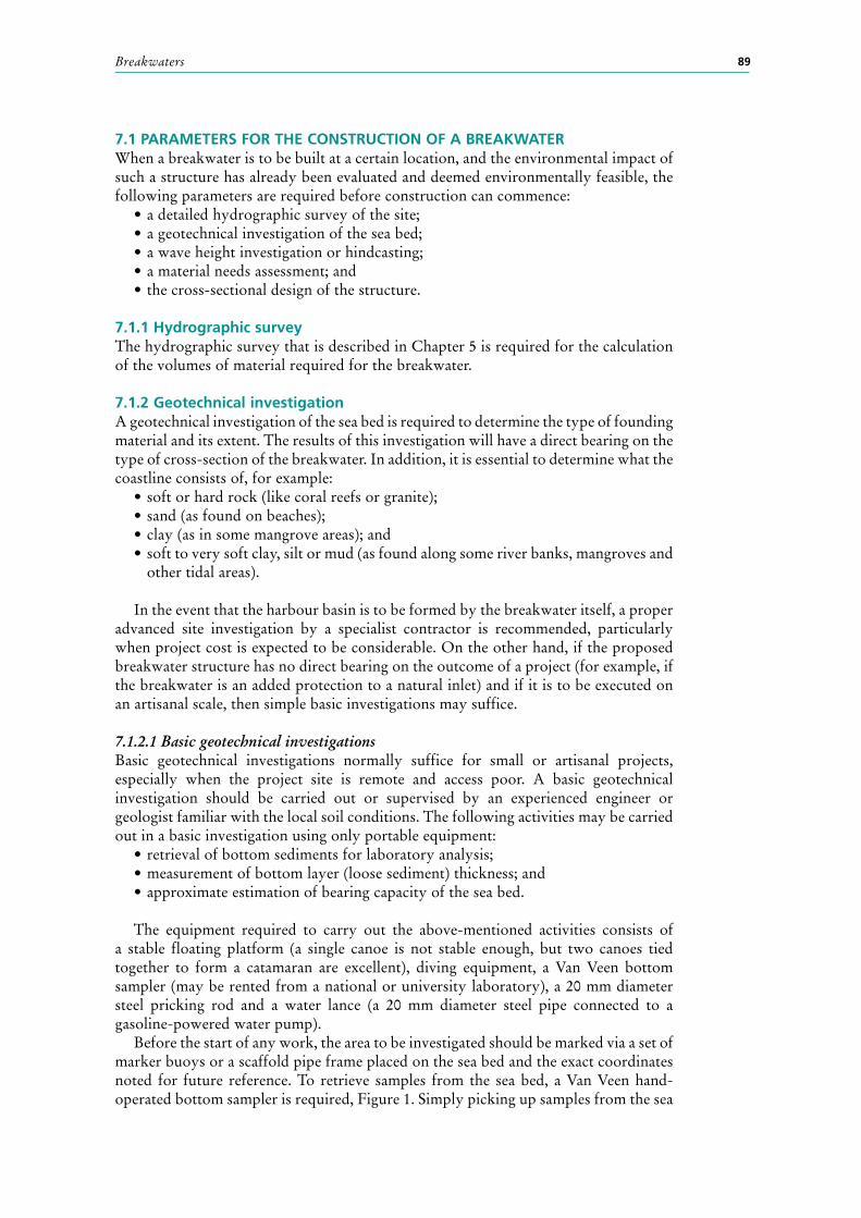
7.1 PARAMETERS FOR THE COnSTRUCTIOn OF A BREAKWATERWhen a breakwater is to be built at a certain location, and the environmental impact of such a structure has already been evaluated and deemed environmentally feasible, the following parameters are required before construction can commence:
• a detailed hydrographic survey of the site;• a geotechnical investigation of the sea bed;• a wave height investigation or hindcasting;• a material needs assessment; and• the cross-sectional design of the structure.
7.1.1 Hydrographic surveyThe hydrographic survey that is described in Chapter 5 is required for the calculation of the volumes of material required for the breakwater.
7.1.2 Geotechnical investigationA geotechnical investigation of the sea bed is required to determine the type of founding material and its extent. The results of this investigation will have a direct bearing on the type of cross-section of the breakwater. In addition, it is essential to determine what the coastline consists of, for example:
• soft or hard rock (like coral reefs or granite);• sand (as found on beaches);• clay (as in some mangrove areas); and• soft to very soft clay, silt or mud (as found along some river banks, mangroves and
other tidal areas).
In the event that the harbour basin is to be formed by the breakwater itself, a proper advanced site investigation by a specialist contractor is recommended, particularly when project cost is expected to be considerable. On the other hand, if the proposed breakwater structure has no direct bearing on the outcome of a project (for example, if the breakwater is an added protection to a natural inlet) and if it is to be executed on an artisanal scale, then simple basic investigations may suffice.
7.1.2.1 Basic geotechnical investigationsBasic geotechnical investigations normally suffice for small or artisanal projects, especially when the project site is remote and access poor. A basic geotechnical investigation should be carried out or supervised by an experienced engineer or geologist familiar with the local soil conditions. The following activities may be carried out in a basic investigation using only portable equipment:
• retrieval of bottom sediments for laboratory analysis;• measurement of bottom layer (loose sediment) thickness; and• approximate estimation of bearing capacity of the sea bed.
The equipment required to carry out the above-mentioned activities consists of a stable floating platform (a single canoe is not stable enough, but two canoes tied together to form a catamaran are excellent), diving equipment, a Van Veen bottom sampler (may be rented from a national or university laboratory), a 20 mm diameter steel pricking rod and a water lance (a 20 mm diameter steel pipe connected to a gasoline-powered water pump).
Before the start of any work, the area to be investigated should be marked via a set of marker buoys or a scaffold pipe frame placed on the sea bed and the exact coordinates noted for future reference. To retrieve samples from the sea bed, a Van Veen hand-operated bottom sampler is required, Figure 1. Simply picking up samples from the sea

Fishing harbour planning, construction and management90
bed with a scoop or bucket disturbs the sediment layers with the eventual loss of the finer material and is not a recommended method. The sediments thus collected should then be carefully placed in wide-necked glass jars and taken to a national or university laboratory for analysis. At least 10 kilograms of sediment are normally required by the laboratory for a proper analysis.
Sometimes, a good hard bottom is overlain by a layer of loose or silty sand or mud. In most cases this layer has to be removed by dredging to expose the harder material underneath. To determine the thickness of this harder layer, a water lance is required. This consists of a length of steel tubing (the poker), sealed at the bottom end with a conical fitting and connected to a length of water hose at the top end. The water hose is connected to a small gasoline-powered water pump drawing seawater from over the side of the platform. The conical end has four 3 mm diameter holes drilled into it.
The diver simply pokes the steel tube into the sediment while water is pumped into it from above until the poker stops penetrating, Figure 2. The diver then measures the penetration. This method, also known as pricking, works very well in silty and muddy deposits up to 2 to 3 metres thick. It is not very effective in very coarse sand with large pebbles.
FIGURE 1The Van Veen bottom sampler
WINCH
STABLE PLATFORM MARKER BUOYS
MARKER BUOYS
MEAN SEA LEVEL
VAN VEEN HAND-OPERATED GRAB
FIGURE 2The water lance used to “prick” the sea bed
STABLE PLATFORM
GASOLINE-POWERED WATER PUMPMEAN SEA LEVEL
SEA WATER PUMPED INTO PIPE
25 mm WATER HOSE
20 mm DIAMETER STEEL PIPE
SCAFFOLD PIPE FRAME
END CONE WITH 4 X 3 mm DIAMETER HOLES

Breakwaters 91
Once the layer of soft sediment has been identified (sampled) and measured (pricked), it is then necessary to determine the hardness of the underlying layer. The underlying layer may be rock, clay or compacted sand. If the layer is rocky, the diver should collect a piece of the material for laboratory analysis using a hammer and chisel. For softer types of material, the diver (with a submerged weight of around 10 kilograms) should use a steel probe (1 metre long, 12 millimetres in diameter) or pocket penetrometer, Figure 3. An area of around 300 mm square should be cleaned of loose sediment and the probe or penetrometer placed vertically over it. The 10-kilogram exertion on the probe will cause the probe to penetrate into the material. The diver then notes the penetration for the engineer to estimate the bearing capacity. If a pocket penetrometer is used, the bearing capacity may be read off the penetrometer scale directly.
7.1.2.2 Advanced geotechnical investigationsAn advanced geotechnical investigation normally requires the retrieval of undisturbed core samples, Figure 4, taken from the level of the sea bed down to a depth ranging from
10 to 30 metres, depending on the type of structure envisaged and the ground conditions obtaining at the site.
Advanced geotechnical investigations are normally carried out by specialist contractors or soil laboratories and require a mobile drilling rig. The drilling rig can travel to most destinations but must be installed on a stable platform before it can be used to drill for cores over water, Figure 5.
FIGURE 3Estimating the bearing capacity of the foundation
A POCKET PENETROMETER
MEAN SEA LEVEL
DIVER – WEIGHT IN WATERAROUND 10 KG 20 mm DIAMETER STEEL ROD
SCAFFOLD PIPE FRAME
FIGURE 4 Core samples of hard clay retrieved from
15 metres below sea bed

Fishing harbour planning, construction and management92
7.1.3 Wave hindcastingThe height of wave incident on a breakwater generally determines the size and behaviour of the breakwater. It is hence of the utmost importance to obtain realistic values of the waves expected in a particular area. Behaviour of water waves is one of the most intriguing of nature’s phenomena. Waves manifest themselves by curved undulations of the surface of the water occurring at periodic intervals. They are generated by the action of wind moving over a waterbody; the stronger the wind blows, the higher the waves generated. They may vary in size from ripples on a pond to large ocean waves as high as 10 metres.
Wind generated waves cause the most damage to coastal structures and if winds of a local storm blow towards the shore, the storm waves will reach the shore or beach in nearly the form in which they were generated. However, if waves are generated by a distant storm, they travel hundreds of miles of calm sea before reaching the shore as swell. As waves travel across the sea they decay (they loose energy and get smaller and smaller) and only the relatively larger waves reach the shore in the form of swell.
Wave disturbance is also felt to a considerable depth and, therefore, the depth of water has an effect on the character of the wave. As the sea bed rises towards the shore, waves eventually break. The precise nature of the types of wave incident on a particular stretch of shoreline, also known as wave hindcasting, may be investigated by three different methods:
• Method 1 – On-the-spot measurement by special electronic equipment, such as a wave rider buoy, which may be hired for a set time from private companies or government laboratories;
• Method 2 – Prediction by statistical methods on a computer – statistical hindcast models may be performed on the computer if wind data or satellite wave data are available for the area; and
• Method 3 – On-the-spot observation by simple optical instruments – the theodolite.
Methods 1 and 2 give very accurate results but are expensive, especially the hire of the wave rider buoys; they are usually reserved for big projects where precise wave data gathered over a period of time is of the utmost importance.
In Method 1, the observer is an electronic instrument capable of recording continuously on a 24-hour basis far out at sea where the waves are not yet influenced by the coastline (depth of water). Hiring a wave rider buoy and installing it may take anywhere up to six months, depending on the method of procurement and water depth and weather conditions at the site. A minimum of one year’s observations is required but generally three to five years provide more accurate data.
FIGURE 5A mobile rig temporarily installed on a trawler to drill over water

Breakwaters 93
Method 2 is currently the standard worldwide method of establishing the wave climate along most coastlines. The huge amount of wind and wave data gathered by specialist agencies worldwide now enables most computer models to zero-in on most sites. Offshore wave climate data is nowadays compiled from hindcasting methods using detailed wind records available for most areas from weather information agencies. Inshore wave climates are then derived on a case-by-case basis from knowledge of the local bathymetry. At today’s prices, the cost of a detailed inshore wave climate is in the range of US$50 000, excluding the cost of the detailed hydrographic survey required for the area under study. Depending on how much raw data is already processed by the specialist agencies and if detailed bathymetry already exists, a good wave hindcast report takes about one month to produce.
Method 3 is not accurate but is cheaper and lies more within the scope of artisanal projects. It differs from Method 1 in one respect only, in that the observer is a normal surveyor with a theodolite placed at a secure vantage point observing waves close to the shoreline, Figure 6. This method, however, suffers from the following drawbacks:
• The wave heights thus recorded will already be distorted by the water depths close to the shoreline.
• A human observer can only see waves during daylight hours, effectively reducing observation time by a half.
• In very bad weather, strong winds and rain drastically reduce visibility making it difficult to keep the buoy under observation continuously.
• The presence of swell is very difficult to detect, especially during a local storm, due to the very long time (period) between peaks, typically 15 seconds or more.
Hence, this method of calculating wave heights is only suitable for minor artisanal projects with a very small capital outlay. To set up a wave monitoring station is easy and the equipment needed consists of two large buoys (one fluorescent and one white), say 750 millimetres in diameter, a large stone and concrete sinker weighing at least 1 tonne in water, a length of 12 mm nylon rope, a theodolite, a compass and a watch with a second hand or digital readout. At a vantage point, which should be just high enough above sea level to be safe and dry during a storm, a stone pillar should be erected with an anchor screw concreted in at the top so that every time the theodolite is set up it faces the same way in exactly the same position, Figure 6. Apart from the time it takes to set up the theodolite station, observations of major waves may only be undertaken during major storms. Hence this method may take at least one year to produce enough data to be useful for a study.
The two plastic buoys should then be moored a known distance offshore where the water depth is exactly 20 metres, the white buoy to the sinker and the red fluorescent buoy to the white buoy, as shown in the figure. The white buoy keeps the mooring line taut and vertical while the red fluorescent buoy floats freely on the incoming waves.
To calibrate the station, the theodolite should be pointed at the buoy on a very calm day. A witness mark should then be placed on something robust (a wall, for example, is preferable to a tree) in such a manner that the observer can re-point the eyepiece at the buoy in its rest position (even if the buoy is actually bouncing up and down with the incoming waves during a storm) at a later date. In this way the theodolite is not tied up completely with wave height observations but can be used for other work as well in between storms. During a storm, the buoy will float up and down with the passage of the waves. By following the base of the buoy with the same centreline hairlines, the theodolite is made to traverse a small angle, Z, as shown in the figure. Using basic surveying principles, the distance A and angle Z may be used to calculate the height H of a wave which, as a rule of thumb, is twice the height of the displacement above calm water level.

Fishing harbour planning, construction and management94
During wave height observations, the following additional information should also be recorded:
• direction of both the incoming waves and wind using the hand-held compass;• the time difference between each successive wave peak, also known as wave period
using the second hand on a watch;• the exact position of the buoy with respect to the coastline; and• time of the year when each storm was recorded.
It must be re-emphasized at this stage that this calculation and the method used are only very approximate and suitable for minor projects only.
7.1.4 Material needs assessmentGiven that most breakwaters consist of either rock or concrete or a mixture of both, it is evident that if these primary construction materials are not available in the required volume in the vicinity of the project site, then either the materials have to be shipped in from another source (by sea or by road) or the harbour design has to be changed to allow for the removal of the breakwater (the site may have to be moved elsewhere).
To calculate the volume of material required to build a rock breakwater, for example, equidistant cross-sections are required. Each cross-section consists of the
FIGURE 6 Manual wave height measurement
Redbuoy
View through eyepiece oftheodolite
1 00
0 - 1
500
mm
X2
X1
500 mm
A about 100 mB about 100 m also
Observation pillar in stoneand concrete
Solid objectpreferred to tree
2 - 3 m
X1
White buoy
Red buoy
Calm sea
MSL
X2
X
Rough sea
300
mm
x
Z
View through eyepiece during the passage of incoming waves

Breakwaters 95
proposed structure outline superimposed on a cross-section of the sea bed. Figure 7 shows a grid map with five cross-sections. Figure 7 (middle) also shows cross-section number 2 of the sea bed, with the breakwater cross-section superimposed on it. Each cross-section may then be divided into known geometric subdivisions, like triangles (A and F) and trapezia (B, C, D and E), whose areas are given by standard formulae. In this way, area 2 is given by the sum of areas A + B + C + D + E + F. Similarly, areas 1, 3, 4, 5, etc. may be calculated from the hydrographic chart. The volume of material required is then the sum of volume 1 + volume 2 + volume 3 + volume 4, etc., as shown in Figure 7. Each segment of breakwater, say volume 1, is given by the average of the sum of (area 1 + area 2) multiplied by the distance between sections 1 and 2, in this
FIGURE 7Calculating the volumes of rock in a breakwater
5 m
-2.15 -1.85 -1.50 -1.05 -0.50
-2.05 -1.70 -1.45 -0.95 -0.30
-1.95 -1.50 -1.05 -0.55 -0.20
-1.85 -1.40 -0.85 -0.65 -0.35
5 o
r 10
met
res
Fishing harbour planning, construction and management96
case, 5 or 10 metres. Mathematically, this can be expressed as 1/2 [area 1 + area 2] x 5 metres. Once the volume of rock has been determined, the most likely source has to be investigated for:
• supply (must be large enough to supply all the rock);• quality (not all rock is suitable for a breakwater);• environmental impact (removing rock from the source must not cause negative
impact there);• mining methods (depending on the type of rock, it may have to be blasted, ripped
or broken); and• means of transport (if roads do not exist between source and project site, then
other means of transport are required).
7.1.5 Cross-sectional designLast but not least, a suitable cross-sectional design for the breakwater has to be produced taking into consideration all the previous data, for example:
• water depths (in deep water, solid vertical sides are preferred to save on material);
• type of foundation (if ground is soft and likely to settle, then a rubble breakwater is recommended);
• height of waves (rubble breakwaters are more suitable than solid ones in the presence of larger waves); and
• availability of materials (if no rock quarries are available in the vicinity of the project, then rubble breakwaters cannot be economically justified).
In general, expert advice should always be sought before embarking on the design of a breakwater cross-section. As was mentioned earlier, waves are one of nature’s least understood phenomena and considerable experience is required when designing breakwaters. If expert advice is not available, the following rules of thumb may be applied to very small projects with water depths not exceeding 3.0 metres:
For rubble mound or rock breakwaters:• Unaided breakwater design should not be attempted in waters deeper than
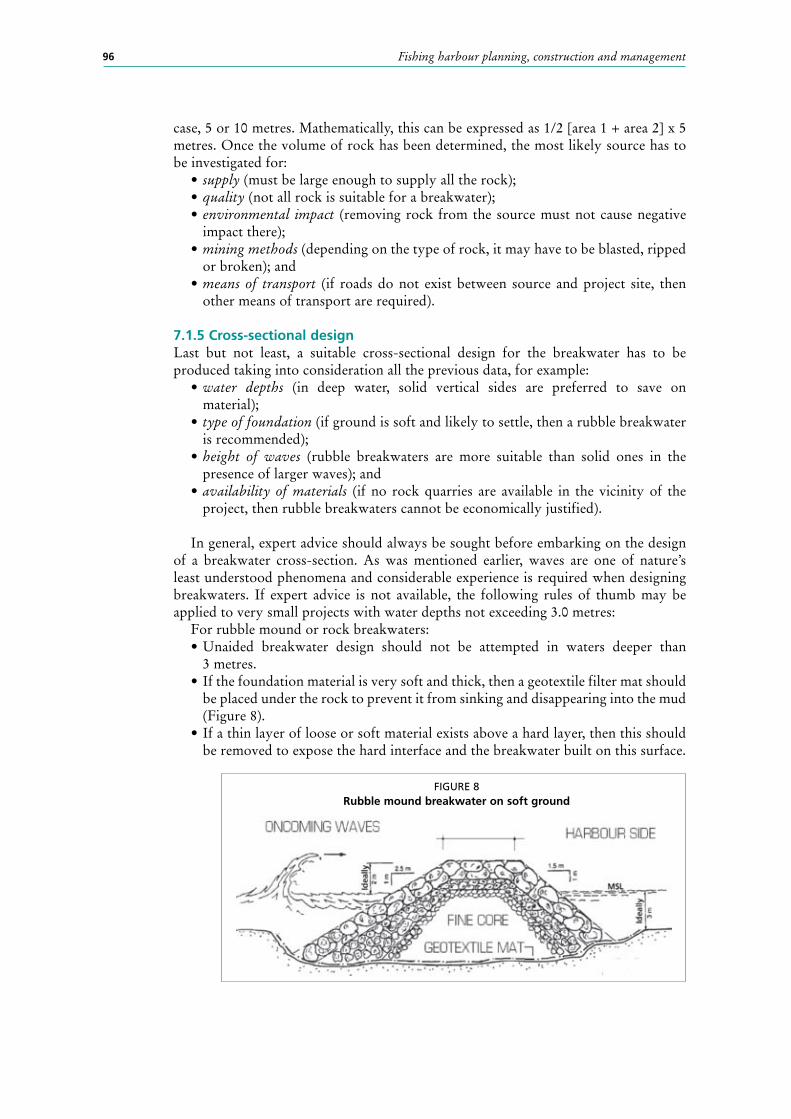
3 metres.• If the foundation material is very soft and thick, then a geotextile filter mat should
be placed under the rock to prevent it from sinking and disappearing into the mud (Figure 8).
• If a thin layer of loose or soft material exists above a hard layer, then this should be removed to expose the hard interface and the breakwater built on this surface.
FIGURE 8Rubble mound breakwater on soft ground

Breakwaters 97
• The material grading should be in the range of 1 to 500 kilograms for the fine core, 500 to 1 000 kilograms for the underlayer and 1 000 to 3 000 kilograms for the main armour layer, Figure 9.
• Dust and fine particles should not be placed in the core as these will wash away and cause the breakwater top to settle unevenly.
• The outer slope should not be steeper than 1 on 2 and the inner or harbour side slope not steeper than 1 on 1.5 (Figure 8).
• In general, rock breakwaters absorb most of the wave energy that falls on them and reflect very little disturbance back from the sloping surface.
For solid or vertical breakwaters:• Unaided vertical solid breakwater design should not be attempted in waters
deeper than 2 metres and exposed to strong wave action, Figure 10.• Vertical solid breakwaters are only suitable when the foundation is a firm surface
(rock, stiff clay, coral reef); thick sand deposits may also be suitable under certain conditions.
• In the presence of thick sand deposits, a rubble foundation with adequate scour protection as shown in Figure 10 is recommended lest strong tidal streams, water currents or wave turbulence scour away the sand underneath the foundation.
• The core of a solid breakwater should be cast in concrete; not more than 50 percent of this concrete may be replaced by pieces of rock or “plums”.
FIGURE 9Rubble mound breakwater on hard ground
2.5 m
2 m
1 m
1.5 m
1 m
MSL
3 m
Idea
lly
Underlayer
Main armour layer
FIGURE 10A solid vertical breakwater on hard ground
MASS CONCRETE CORE
TOE PROTECTION IN CONCRETE-FILLED JUTE BAGS HEIGHT NOT MORE THAN 2.0 m
>
>
>
>
CONCRETE-FILLED JUTE BAGS
Fishing harbour planning, construction and management98
Great care should be exercised when deciding the position of a solid breakwater. Solid vertical breakwaters do not absorb wave energy incident on them and reflect everything back, usually causing other parts of a harbour to experience “choppy-sea” conditions.
7.2 COnSTRUCTIOn METHODSThere are several types of equipment available for marine construction, both land-based and floating. The high cost of purchase, however, puts most of this equipment beyond the reach of village cooperatives, artisanal contractors and small general-building contractors.
Hence, it is assumed that most of the heavy plant will be made available through the government or public works department, or local contractors, and this chapter should be used as a guide to the general type of equipment required for marine work. Large specialist marine contractors often use floating equipment (all cranes mounted on barges, for example, and material like the core is often dumped using barges). When planning the construction of a marine-related project, it would be useful to know beforehand what type and size of construction plant is available in the vicinity of the village or landing.
7.2.1 land-based equipment
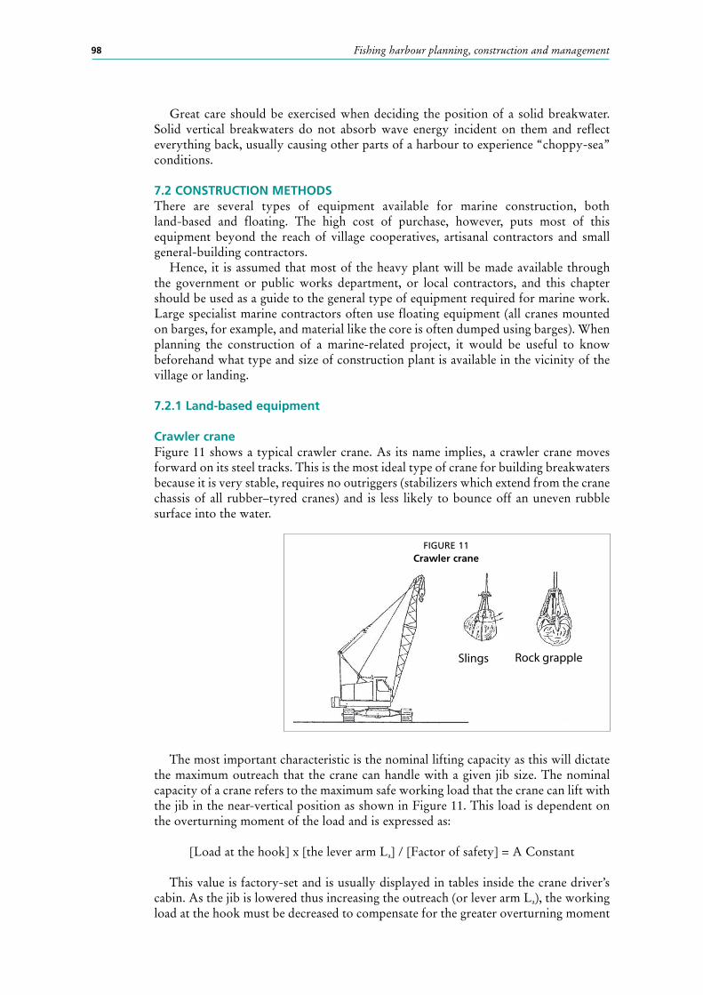
Crawler craneFigure 11 shows a typical crawler crane. As its name implies, a crawler crane moves forward on its steel tracks. This is the most ideal type of crane for building breakwaters because it is very stable, requires no outriggers (stabilizers which extend from the crane chassis of all rubber–tyred cranes) and is less likely to bounce off an uneven rubble surface into the water.
The most important characteristic is the nominal lifting capacity as this will dictate the maximum outreach that the crane can handle with a given jib size. The nominal capacity of a crane refers to the maximum safe working load that the crane can lift with the jib in the near-vertical position as shown in Figure 11. This load is dependent on the overturning moment of the load and is expressed as:
[Load at the hook] x [the lever arm La] / [Factor of safety] = A Constant
This value is factory-set and is usually displayed in tables inside the crane driver’s cabin. As the jib is lowered thus increasing the outreach (or lever arm La), the working load at the hook must be decreased to compensate for the greater overturning moment
FIGURE 11 Crawler crane
Slings Rock grapple
Breakwaters 99
of the load. Failure to observe the proportional reduction in the suspended load as indicated in the crane’s tables will result in the crane overturning. Figure 11 also shows two typical attachments required for lifting and placing rock: slings and grapples. Most slings are made from steel wire rope and these should terminate in quick-release shackles to enable the crane driver to release the rock himself once it has been placed. Rock grapples are the industry standard for handling rock. If a rock grapple is used, the weight of the grapple (anything from 500 to 3 000 kilograms) must be subtracted from the safe working load specified for a particular crane.
SAFETY PRECAUTIONSThe crane driver should always wear a hard hat and soundproof earmuffs. Consequently, it is essential to put in place a signalling system between the load handlers and the driver. Load handlers should always wear hard hats and gloves. If the loads are handled with steel-wire ropes, then the appropriate gloves should be worn to prevent injuries.
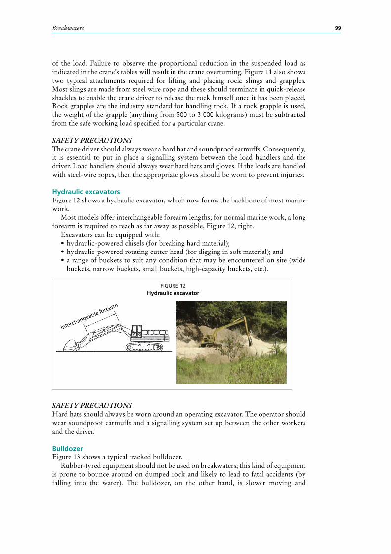
Hydraulic excavatorsFigure 12 shows a hydraulic excavator, which now forms the backbone of most marine work.
Most models offer interchangeable forearm lengths; for normal marine work, a long forearm is required to reach as far away as possible, Figure 12, right.
Excavators can be equipped with:• hydraulic-powered chisels (for breaking hard material);• hydraulic-powered rotating cutter-head (for digging in soft material); and• a range of buckets to suit any condition that may be encountered on site (wide
buckets, narrow buckets, small buckets, high-capacity buckets, etc.).
SAFETY PRECAUTIONSHard hats should always be worn around an operating excavator. The operator should wear soundproof earmuffs and a signalling system set up between the other workers and the driver.
BulldozerFigure 13 shows a typical tracked bulldozer.
Rubber-tyred equipment should not be used on breakwaters; this kind of equipment is prone to bounce around on dumped rock and likely to lead to fatal accidents (by falling into the water). The bulldozer, on the other hand, is slower moving and
FIGURE 12Hydraulic excavator
Interchangeable forearm

Fishing harbour planning, construction and management100
more stable. This kind of machine is essential when building breakwaters as it is required to level the fine core material as it is forward dumped into the sea. Bulldozers may be equipped with blades (for levelling the core of a breakwater) or buckets. The operator’s cabin may be sealed or open to the elements as shown in the figure.
SAFETY PRECAUTIONSThe operator should wear both a hard hat and earmuffs and a signalling system set up between other workers and the driver.
Tipper trucksFigure 14 shows the recommended type of truck required for transporting and dumping of rubble.
If proper tipper trucks are not available for a project, then a farm tractor and trailer combination may be adapted to carry rock, aggregates and sand from a quarry to a project site. Considerably more use of direct labour is involved, but at local village level this should not present any problems. The trailers should preferably be made of steel and should be protected on the inside with timber planking. The timber prolongs the useful life of the trailer by absorbing the impacts of individual stones thrown onto the trailer. Care should be exercised when traversing the uneven surface of a rubble core with all rubber-tyred vehicles.
SAFETY PRECAUTIONSAll personnel should wear hard hats.
FIGURE 14Tipper trucks and forward dumping
Farm tractor
Steel trailer
FIGURE 13Bulldozer

Breakwaters 101
7.2.2 Floating equipment
Floating craneFigure 15 shows a typical barge-mounted crane. The crane is either bolted or welded directly to the hull or driven on to the barge and lashed down with cable stays.
The crane can revolve through 360 degrees and the deck of the barge is usually lined with timber so that rock may be placed on the deck without damaging it. The stability of the crane in this instance is dictated by the stability of the barge and field conversions should always be checked for stability by an experienced naval architect. Normally, such cranes need a tugboat or fishing vessel to help them move from one place to another. Exact positioning is usually achieved by anchors.
SAFETY PRECAUTIONSAll personnel should wear hard hats. The barge should be equipped with the safety requirements stipulated for shipboard operations (life jackets, flares, raft, etc.), including MARPOL recommendations for the prevention of pollution at sea.
TugboatFigure 15, bottom right, shows a tugboat of the type generally used by marine contractors. The horsepower of these vessels may be anywhere from 200 to 2 000 hp, depending on the type of plant to be handled. Common sizes are in the range of 250 to 500 hp.
SAFETY PRECAUTIONSThe tugboat should be equipped with the safety requirements stipulated for shipboard operations (life jackets, flares, raft, etc.), including MARPOL recommendations for the prevention of pollution at sea.
FIGURE 15 Floating crane

Fishing harbour planning, construction and management102
Hopper barge Figure 16 shows a general purpose hopper barge used for the transport and dumping of material at sea. Commonly, available barges have a capacity in the range of 500 to 1 000 cubic metres and are generally self-propelled. Hopper barges can be used for dumping the core of a breakwater in deep water (5 metres and deeper) and for dumping excavated or dredged material offshore.
SAFETY PRECAUTIONSThe hopper barge should be equipped with the safety requirements stipulated for shipboard operations (life jackets, flares, raft, etc.), including MARPOL recommendations for the prevention of pollution at sea.
7.2.3 MethodologiesThe typical breakwater illustrated in Figure 8 (shallow water only) consists of a mound of coarse stone, also known as a core, covered or protected by blankets or layers of heavier stones.
7.2.3.1 The core The core typically consists of stone weighing between 1 kilogram and 500 kilograms, without the fine particles (dust and sand) dumped in a heap out into the sea by a dump truck. To facilitate dumping by truck, the core should be ideally four to five metres wide at the top and approximately half a metre above mean sea level or, in the presence of a large tidal range, above high water spring level, Figure 17a. The top of the core should be kept level and uniform by a bulldozer to enable the dump trucks to travel the entire length of the breakwater. When tipped into the water, the core rubble comes to rest at a slope of approximately 1 on 1, i.e. it drops down 1 metre in level for every 1 metre forward. The rubble in the core is very light, so breakwaters should be built during calm weather only.
Environmentally speaking, the core dumping may have a large negative impact on the surrounding sea due to the fine dust that gets washed off the rubble. In environmentally sensitive areas, such as coral reefs, protected fish breeding areas and nursery grounds rich in certain species of protected vegetation such as Posidonia sea grass, the core must be sluiced or washed before placing to limit the dust plume that would otherwise be generated by the fine dust particles. This dust plume usually persists for many days and can cause a lot of damage by either blocking out sunlight or depositing fine dust on the gills of fish and suffocating them.
FIGURE 16 The split hopper barge

Breakwaters 103
7.2.3.2 The underlayerThe underlayer of stone that protects the core rubble from being washed away,Figure 17b, usually consists of single pieces of stone whose weight varies between a minimum of half a tonne (500 kilograms) to a maximum of one tonne (1 000 kilograms). These are usually laid in a minimum of two layers at a slope which is generally shallower than that of the core; 2/1 on the outer slope and 1.5/1 on the inner slope. A slope of 2/1 means that the level drops 1 metre for every 2 metres forward.
FIGURE 17 Rubble mound construction
Minimum size 1 kg
Maximum size 500 kg
Dense limestone
1 m1 m
1 m1 mMSL
Minimum
3 m
MSL 0.5 m
Tipping by truck
Fine core
Cross-section
Nylon string
Sinker
2.5 x H
600 mm
900 mm
Minimum size 500 kg
Maximum size 1 000 kg
A hydraulic excavator placing therubble on the crown of the breakwater
Fine core
Maximum corelength exposed 10 m
900 mm
1 300 mm
Nylon
profile
3:1 Slope around the headincreased to 3:1
The same machine backtrackingand closing the crown at thesame time
Rubble deliveredby truck
Sinker
This outreachrequires a crane Minimum size 1 000 kg
Maximum size 3 000 kgDiver
Placing the main armour layer
17 a
17 b
17 c
17 d

Fishing harbour planning, construction and management104
The first layer of stone may be placed by a hydraulic excavator as shown in Figure 17c. The excavator should place the heavier stone as quickly as possible without leaving too much core rubble exposed to wave action. If a storm strikes the site with too much core exposed, there is a grave danger of the core being washed away and spread all over the intended port area.
The figure shows the set up for a given stone profile, in this case a slope of 2.5/1: the distance H is the height of the top of the new sloping layer above the sea bed. A wooden pole should be conveniently placed at the tip of the underlying core and cemented into place with mortar. At a distance equal to 2.5 x H, a heavy stone sinker with a marker buoy should be placed on the sea bed. A brightly coloured nylon string should then be strung from the sinker to the required height on the pole. This procedure should be repeated every 5.0 metres to help the crane or excavator operator with the placing of the top-most layer. A swimmer wearing goggles (and in cold waters a wet suit) should ensure that each separate rock is placed within the profile outlined by the nylon string.
7.2.3.3 The armour layerThe main armour layer, as its name implies, is the primary defence of the breakwater against wave attack. The stone sizes for the cross-section in the shallow water example should be in the range of 1 tonne (1 000 kilograms) to 3 tonnes (3 000 kilograms). Any defects in the quality of the rock, grading (size too small) or placing (slope uneven or too steep) will seriously put the whole breakwater at risk. Hence, great care must be taken when choosing and placing the stone for the main armour layer.
Figure 17c shows main armour stone being placed by a crawler crane or tracked crane, which is by far the best equipment for placing large stones. The large stones should be lifted singly using a sling or stone grapple and placed in the water with the aid of a diver swimming over the placing area. The armour layer should be placed stone by stone in a sequence which ensures interlocking; in the figure, for example, stone 2 is held in place by stones 1 and 3 whereas stone 4 is jammed between stones 3 and 5. This ensures that waves cannot pull one stone out and cause the upper stones to topple down the slope, breach the armour layer and expose the smaller rubble underneath. To ensure proper placing, the swimmer or boat crew should direct the crane operator each time a stone is placed until the stone layer breaks the surface. As with the first underlayer, two layers of armour stones are required to complete the main armour layer. Slope profiles should be set up at regular 5 metre intervals using the same procedure as described previously. Figure 17d, bottom, shows how the nearly complete breakwater is closed off layer by layer. It shows the excavator backtracking to the root of the breakwater closing the top layers simultaneously. The end or head of the breakwater is the most delicate part of the breakwater and requires extra care. The outer slope of 2.5/1 should be increased to 3/1 to improve its stability.
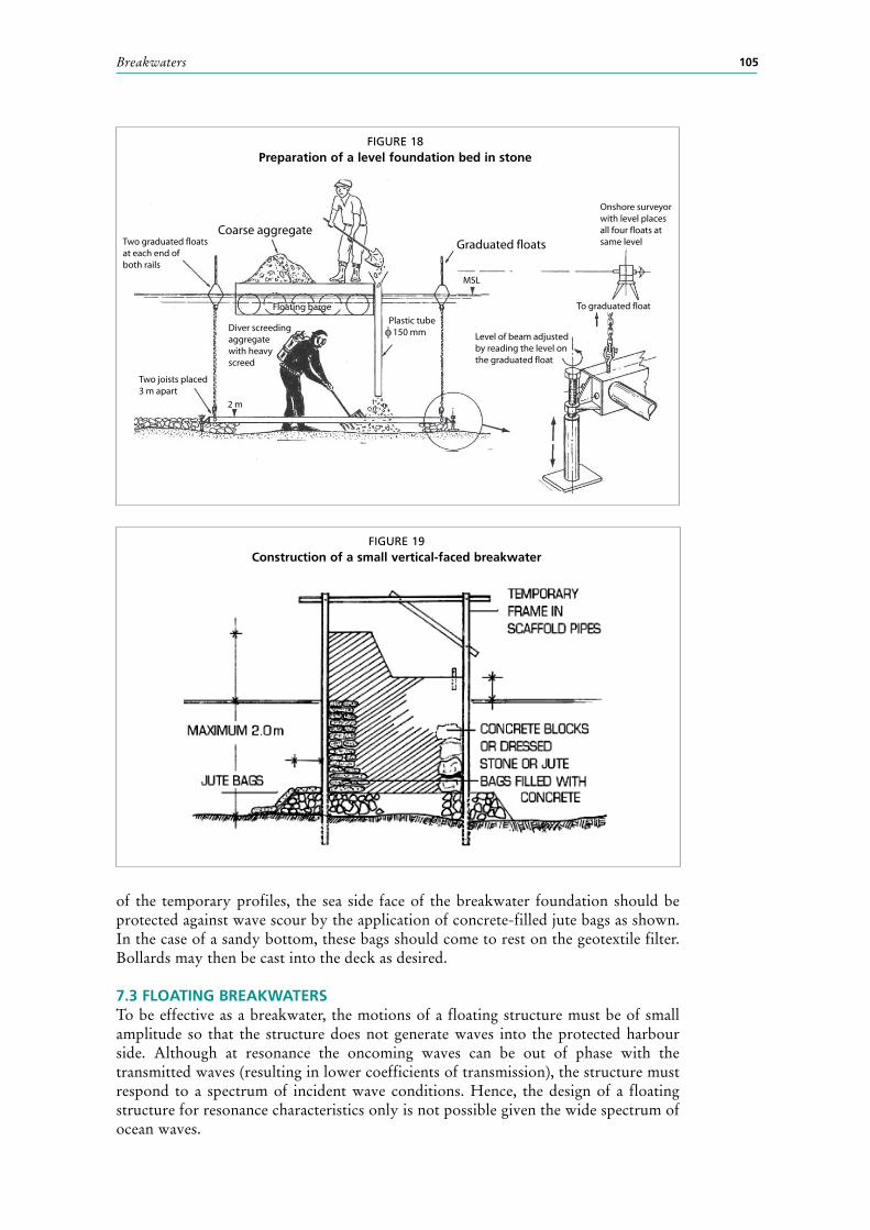
7.2.3.4 Solid breakwaterFigure 19 illustrates how a vertical, solid breakwater may be built. A stone rubble foundation should first be laid on a hard sea bed (rock, coral deposits or stiff clay) using the appropriate equipment illustrated in Figure 18. If the foundation is a thick deposit of good sand (no silt or soft clay or mud), then a geotextile filter mat should be placed under the rubble foundation. The rubble should consist of a well-graded mix of 1- to 5-kilogram stones. A temporary profile of the proposed section should then be erected every 2 or 3 metres as shown in Figure 19.
Concrete filled jute bags, or locally available dressed stone, should then be laid on the rubble foundation, in line with the temporary profiles. Mass concrete should then be poured into the central cavity to form a solid structure. The deck and wave wall may be built to suit local conditions or as shown in the figure. Finally, after the removal
Breakwaters 105
of the temporary profiles, the sea side face of the breakwater foundation should be protected against wave scour by the application of concrete-filled jute bags as shown. In the case of a sandy bottom, these bags should come to rest on the geotextile filter. Bollards may then be cast into the deck as desired.
7.3 FlOATInG BREAKWATERSTo be effective as a breakwater, the motions of a floating structure must be of small amplitude so that the structure does not generate waves into the protected harbour side. Although at resonance the oncoming waves can be out of phase with the transmitted waves (resulting in lower coefficients of transmission), the structure must respond to a spectrum of incident wave conditions. Hence, the design of a floating structure for resonance characteristics only is not possible given the wide spectrum of ocean waves.
FIGURE 18 Preparation of a level foundation bed in stone
Coarse aggregateTwo graduated floatsat each end ofboth rails
Graduated floats
Onshore surveyorwith level placesall four floats atsame level
MSL
Floating barge
Plastic tube 150 mmDiver screeding
aggregatewith heavyscreed
Level of beam adjustedby reading the level onthe graduated float
To graduated float
2 m
Two joists placed3 m apart
φ
FIGURE 19 Construction of a small vertical-faced breakwater

Fishing harbour planning, construction and management106
The simplest forms of floating breakwaters are pontoon structures, although various modifications to their shape have been investigated in an effort to optimize the mass (and ultimately the cost).
The efficiency of a floating breakwater depends primarily on the ratio of the width of the pontoon to the wavelength of the oncoming waves (Figure 20) and, given that ocean swell has a very long wavelength, floating breakwaters are not suitable for creating protected areas along an exposed coastline and should never be installed. However, on lake shores, where the waves tend to be very short (choppy) and do not generally exceed 0.50 metre, floating breakwaters tend to work efficiently.
7.4 BIBlIOGRAPHY AnD FURTHER READInGUS Army Corp of Engineers. 1985. Shore Protection Manual. Washington, D.C., US
Army Corp of Engineers.US Army Corp of Engineers. 1995. Design of Coastal Revetments, Seawalls and Bulkheads
– Engineering and Design. Washington, D.C., US Army Corp of Engineers.
FIGURE 20 Transmission of waves through a floating breakwater