
6800-09506-01E Premium Bagger Gauges … Instructions 2000-2003 and 2004-2013 ... Speed Sensor Gnd...
15
Premium Bagger Gauges ® Installation Instructions 2000-2003 and 2004-2013 6800-09506-01E
Transcript of 6800-09506-01E Premium Bagger Gauges … Instructions 2000-2003 and 2004-2013 ... Speed Sensor Gnd...

Premium Bagger Gauges®
Installation Instructions2000-2003 and 2004-2013
6800-09506-01E

Installation Instructions 2000-2003 and 2004-2013
We recommend a second person to assist with fairing disassembly and reassembly. Fender and tank covers are recommended to help avoid accidental damage.
Common tools and supplies needed:• T27 Torx® driver• #2 Phillips screwdriver• 5/16” nut driver • 1” open-end wrench• Hex wrench set
• Wire cutters• Wire crimpers• Wire ties• Electrician’s tape
Step 1: Preparation
Record the mileage on the existing gauge. Remove the inner fairing screws. TIP: Sometimes these are hard to find. FLT Road Glide® fairings have (6), FLH Street Glide® Fairings have (4).Protect the fender & tank with a cover before you begin disassembly to avoid accidental damage!
Step 2: Remove Fairing
TIP: This is where having a second person to hold the outer fairing would be helpful.
On FLH fairings, loosen the (3) windscreen screws and only remove the outer two screws. Leave the middle screw in place but loose. Remove the windscreen by wiggling gently and set it aside. Hang onto the outer fairing while removing the middle screw and trim. Unplug the headlamp connector [2a] and set the fairing aside.On Road Glide FLT type fairing the windscreen doesn’t need to be removed to disassemble the fairing, but it will be easier to reassemble the fairing without it. It can also prevent damaging the black decal on the windscreen during reassembly. Begin by removing the turn signals from each side of the fairing. Lift the outer fairing off the inner and disconnect the headlight [2a] and set the outer fairing aside.
1
SCREWS

2a
DISCONNECT
2b
Step 3: Disconnect Factory Gauges
Start by removing the connectors from the back of each gauge. It is easier to remove the top two smaller gauges first in order to have room to access the two lower ones. You might have to cut some wire ties in order to move the harness and connectors around. DO NOT REMOVE the factory harness. It will remain on the fairing.
Step 4: Replace Small Gauges
TIP: It’s easier to put the wire harness on as you insert each gauge. See step 6 for details.
Replace each small gauge one at a time, starting with the lower two. Place one hand on the front of the gauge and remove the two bracket nuts [4a] on the back of each gauge using the 5/16” nut driver. Push the gauge out and remove the bracket. Slide the rubber gauge retainer sleeves onto the replacement gauge aligning the rib on the gauge with the mating notch [4b]. Insert the gauge & retainer assembly into the fairing opening wiggling it into place until the rubber lip [4c] pops out on the back side of the fairing. A soapy solution on the leading edge of the rubber will help the rubber retainer slip into place. Make sure the ribs on the rubber retainer in the notches on the fairing opening and the retaining lip is out all the way around the back of the fairing. Make sure the red covers [4b] are on the ends of the threaded studs.
DISCONNECT
3

4a
4b
RUBBERGAUGE
RETAINER
RETAININGLIP
4c
RETAININGLIP
Step 5: Replace Large Gauges
TIP: It’s easier to put the wire harness on as you insert each gauge. See step 6 for details.
Replace each large gauge one at a time. Place one hand on the front of the gauge and remove the two bracket nuts on the back of the gauge. Push the gauge out and remove the bracket. Position the rubber gasket on the replacement gauge and align the notch with the corresponding rib on the gauge housing. Insert the gauge into the fairing opening aligning the rib on the gauge with the notch in opening. Hold the gauge in place with one hand while installing the bracket and nuts provided. Tighten the nuts to secure the gauge snugly in the fairing, but do not over tighten. Make sure the red covers are on the end on the threaded studs. On Road Glide FLT type fairings, install the speedometer and tachometer into the pod and make sure the gauges are aligned and straight to your liking before reassembly.

Step 6: Install the Medallion Gauge Harness
Install the gauge wire harness (The harness with six 4-Pin Plugs) by inserting the 4-pin gauge plugs into each mating connector on the gauges. Any plug can go into any gauge, just install it in logical order to get the wire harness to fit. Push on the front of the gauge while installing the connector so it stays in place. Make sure nothing is pushing on the back of the gauge when finished.
Step 7: Install the Transtion Wire Harness
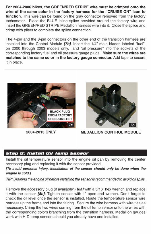
For 2004-2013 bikes only, connect the smaller 12-pin connector to the black plug [7a] that was pulled out of the factory speedometer. Insert the larger 12-pin plug into the back of the tachometer. On Road Glide FLT type fairings, route the end of the transition harness with the two 12-pin connectors through the wire passage tunnel. Route the end of the gauge harness with only the two 4-pin connectors in the same way and insert them into the tachometer and speedometer. Pull back on the harnesses inside the fairing to make room during pod reassembly.
For 2000-2003 bikes only, wires matching the colors of the Medallion transition harness can be found in the factory connectors plugged into the factory speedometer and tachometer. Splice all eleven (11) Medallion harness wires to the matching colors on the factory harness. To finish, shrink the tubing around splice with a heat source.
HD Wire Harness Function and Color
FUNCTION COLOR FUNCTION COLORGround Black Check Engine Black/YellowBattery Orange or Brown/White Speed Sensor In WhiteIgnition Orange/White Tachometer In PinkBacklight In Orange/White Speed Out White/GreenFuel Level Yellow/White Oil PSI Brown/GreenJ1850 Light Green Oil Temperature TanCruise Engaged Green/Red Proprietary Data + YellowSpeed Sensor Gnd Black Proprietary Data - GreenSpeed Sensor Pwr Red
For 2004-2006 bikes, the GREEN/RED STRIPE wire must be crimped onto the wire of the same color in the factory harness for the “CRUISE ON” icon to function. This wire can be found on the gray connector removed from the factory tachometer. Place the BLUE inline splice provided around the factory wire and insert the GREEN/RED STRIPE Medallion harness wire into it. Close the splice and crimp with pliers to complete the splice connection.
The 4-pin and the 8-pin connectors on the other end of the transition harness are installed into the Control Module [7b]. Insert the 1/4” male blades labeled ”fuel”, on 2000 through 2003 models only, and “oil pressure” into the sockets of the corresponding factory fuel and oil pressure gauge plugs. Make sure the wires are matched to the same color in the factory gauge connector. Add tape to secure it in place.
BLACK PLUG FROM FACTORY SPEEDOMETER
2004-2013 ONLY
7a
MEDALLION CONTROL MODULE
7b
Step 8: Install Oil Temp SensorInstall the oil temperature sensor into the engine oil pan by removing the center accessory plug and replacing it with the sensor provided. [To avoid personal injury, installation of the sensor should only be done when the engine is cold.]TIP: Draining the engine oil before installing the sensor is recommended to avoid oil spills. Remove the accessory plug (if available*) [8a] with a 5/16” hex wrench and replace it with the sensor [8b]. Tighten sensor with 1” open-end wrench. Don’t forget to check the oil level once the sensor is installed. Route the temperature sensor wire harness up the frame and into the fairing. Secure the wire harness with wire ties as necessary. Crimp the two wires coming from the oil temp sensor onto the wires with the corresponding colors branching from the transition harness. Medallion gauges work with H-D temp sensors should you already have one installed.

8aREMOVETHIS PLUG
8bSENSOR REPLACES
PLUG
Step 9: Secure Control ModuleTIP: Use electrician’s tape to protect the wire as needed.
Dress and secure the control module (HCM) and any wires to keep them from rattling and to protect them from sharp edges.
Step 10: Reassemble the FairingTIP: Have a second person help.
Power up the gauges and verify they are working before you reassemble the fairing. Reassemble the fairing in the reverse order of how you disassembled it.
Step 11: SetupFollow the Operation & Setup Guide for setup and learning procedures.

LCD Symbol Description
LCD Display Mode Clock, ODOmeter, Trip A, Trip B, SERVice alarm
Current Gear Position DisplayIt does not matter if you have a 5-speed or 6-speed. If the ECU does not broadcast gear information, the gauge can be trained quickly to learn which gear you are in. [See the Setup Menu Below.] If the ECU does broadcast the information, the gauge is ready to use.
Low Fuel IconIcon comes on when the fuel level drops to 20%. If reading is off, follow fuel calibration procedures on the last page.
Low Battery IconThe battery icon is displayed when the battery voltage is below 12.4 VDC.
Cruise Control IconIs displayed when cruise is turned on. The little arrow on the upper left side of the icon is present when cruise is engaged.
NOTE: On 2004-2006 bikes, only the “CRUISE ACTIVE” wire is monitored. This means that the cruise icon will appear only when the cruise is engaged going down the road, but will not appear when the bike is parked and the cruise switch is on.
Bike Odometer [See Setting Odometer Below.]
Trip A is resettable and independent from Trip B. While Trip A is displayed, pressing the right button resets TRIP A odo to zero. While Trip B is displayed, pressing the right button resets TRIP B odo to zero.
Service reminder. This can be set to any mileage. Default from the factory is 500 miles. Pressing and holding the right button allows adjustments.
12 or 24 hour clock available. Setting the clock (LCD Display), press and hold the right button until “12-HOUR” appears. The left button adjusts value, the right button selects the next mode. If no buttons are pressed in five seconds, the new clock setting will be stored.
ENGAGED
ON
Operation & Setup Guide

BIKE - This will adjust the gauge system to operate with the correct fuel level sensor tables and other features that are model year dependent.
UNITS - This changes between English and Metric units displayed on the LCD. The speed in the LCD is always in the opposite units selected and is there as a reference for those that cross the U.S. border. It may be disabled.
AUTO DIM - Auto Dim turns the daylight sensor on or off enabling the LCD display and icons to dim down at night.
SHIFT ICON - The Shift icon is an up arrow that lights up when engine RPM reaches it’s set point. This shift point is programmable. This shift icon can be set to “flash”, “steady” or “disabled”.
GEAR SOURCE - This tells the gauge where to get the gear position. On some bikes the 6th gear is not broadcast. Changing to “gauge” and going through the learn mode will enable gear position. NOTE: Gear position is only displayed while engaged in a gear, and will not display “N”.
Factory Default SettingsBike 2008 or newer LCD Speed: EnabledUnits: English Demo Mode: DisabledAuto Dim: Enabled Set Shift Icon RPM: 3000RPM
(Note: This item is not reset with the factory reset function)Gear Source: ECUSpeed Source: Default
Setup Functions
SETUP
PRESS AND HOLD BOTH
AT SAME TIME
SCROLL DOWN CHANGE VALUE
BIKE:..UNITS:AUTO DIM:SHIFT ICON:
NEXT
2004 or newerMetric
DisabledFlash
CHANGE
To enter the SETUP menu, push and hold both buttons until the LCD displays the word SETUP. The right button changes the option highlighted, the left button scrolls down to the next option.It is recommended to switch the display to ODO prior to entering the SETUP menu. If a TRIP odo is displayed and both buttons are not pushed together you run the risk of resetting the TRIP odo to zero.
Setup Menu

SPEED SOURCE - Allows for the selection of Speed Source to the Gauge: ECU; Trans; or Cable.
LCD SPEED - Used to display the speed units (mph/kph) in the LCD. The units are determined by and are opposite of the Units setting, i.e. English or Metric.
DEMO MODE - This mode is for table top demonstration only. This mode can be enabled, but will NOT operate if the Handlebar Control Module is connected. In this mode the gauges will move through the gears and display icons.
SET SHIFT ICON RPM - The shift icon can be setup to light at any RPM. This is adjusted by 50 RPM steps. Press the RIGHT button to adjust up, and the LEFT button to adjust the RPM value down. Do not press any buttons for 5 seconds to save settings.
START GEAR LEARN MODE - Read below for specific instructions.
ADJUST SPEEDOMETER - This option is used to calibrate the speedometer in the event it should not be accurate. Using a GPS, ride bike at a steady GPS reading of 30mph and select SAVE (Left Button). This will recalibrate the gauge to reflect accurate speed.
SET ODOMETER - Set the mileage recorded from the previous ODOmeter reading referenced in Step 1. See “SETTING ODOMETER” in the following pages for detailed instructions. Odometers in gauges built August 2013 and later can be reset within the first 100 miles to correct and error. Gauges before that date are one-time programable only!
RESTORE DEFAULTS - If something is misadjusted or programmed incorrectly, your gauge can be restored to the original factory settings by highlighting RESTORE DEFAULTS and pressing the RIGHT button. (See FACTORY DEFAULTS table for affected settings)
TACH INFORMATION - This menu displays the software version and build date of the gauge.
FAULT CODES - Prompts the ECU for engine fault codes. If any exist they will be listed with fault number and source.
DIAGNOSTICS - This is the factory menu for diagnosing problems in the instrumentation system. The first page shows the raw values that the microprocessor is looking at. Additional pages are entered by pressing either button. On the second page is the gauge values being sent to the gauges. The third page displays if the gauge is seeing any data on the serial data bus from the engine.
EXIT - Pressing the RIGHT button will cause the gauge to save any changes and then reset gauge.
Setup Functions [continued]
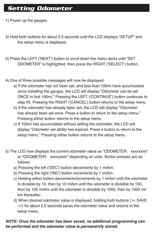
Setting Odometer
1) Power up the gauges.
2) Hold both buttons for about 2.5 seconds until the LCD displays “SETUP” and the setup menu is displayed.
3) Press the LEFT (‘NEXT’) button to scroll down the menu items until “SET ODOMETER” is highlighted, then press the RIGHT (‘SELECT’) button.
4) One of three possible messages will now be displayed: a) If the odometer has not been set, and less than 100mi have accumulated
since installing the gauges, the LCD will display “Odometer can be set ONCE in first 100mi.” Pressing the LEFT (‘CONTINUE’) button continues to step #5. Pressing the RIGHT (‘CANCEL’) button returns to the setup menu.
b) If the odometer has already been set, the LCD will display “Odometer has already been set once. Press a button to return to the setup menu.” Pressing either button returns to the setup menu.
c) If 100mi has accumulated without setting the odometer, the LCD will display “Odometer set ability has expired. Press a button to return to the setup menu.” Pressing either button returns to the setup menu.
5) The LCD now displays the current odometer value as “ODOMETER: xxxxxxmi” or “ODOMETER: xxxxxxkm” depending on units. Button presses are as follows:
a) Pressing the left (‘DEC’) button decrements by 1 mi/km. b) Pressing the right (‘INC’) button increments by 1 mi/km. c) Holding either button decrements/increments by 1 mi/km until the odometer
is divisible by 10, then by 10 mi/km until the odometer is divisible by 100, then by 100 mi/km until the odometer is divisible by 1000, then by 1000 mi/km thereafter.
d) When desired odometer value is displayed, holding both buttons (‘<- SAVE ->’) for about 2.5 seconds saves the odometer value and returns to the setup menu.
NOTE: Once the odometer has been saved, no additional programming can be performed and the odometer value is permanently stored.

Optional Fuel Tank Calibration InstructionsIf the fuel gauge on your bike is reading incorrectly using the factory calibration for that model year, it can be changed using the “CALIBRATE FUEL TANK” option within the gauge SETUP menu.
IMPORTANT NOTES:
1. THE GAUGE WILL NOT READ CORRECTLY UNTIL ALL THREE CALIBRATION POINTS ARE SET, AND THE GAUGE HAS REBOOTED.
2. Calibration points can be set all at one time or different times.
3. Calibration points must be set with the engine running and the bike in an upright position.
4. Calibration can be repeated.
5. DO NOT ADD FUEL WHILE THE ENGINE IS RUNNING!
6. It might be necessary to enter the Setup Menu after each time the engine is restarted.
7. Holding both gauge buttons down simultaneously in the “CALIBRATE FUEL TANK” option will reset the gauge to factory calibration if desired.

1. Ride to a point that you know the bike is near empty, possibly based on your odometer.
2. With the engine running, ENTER the SETUP MENU and SELECT “CALIBRATE FUEL TANK” option.
3. HIGHLIGHT and SELECT “Calibrate
Empty…”, and “Empty Calibrated!” will appear.
4. KILL the engine.
5. Add 2.5 or 3 gallons of fuel depending on your tank size.
6. START the Engine.
7. Enter the SETUP MENU again.HIGHLIGHT and SELECT “Calibrate .…” and “1/2 Calibrated!” will appear.
8. KILL the Engine.
9. Top off the tank.
10. START the Engine.
11. Enter the SETUP MENU again. HIGHLIGHT and SELECT “Calibrate Full…”, and “Full Calibrated” will appear.
12. HIGHLIGHT and SELECT “Back”. 13. HIGHLIGHT and SELECT Exit and the
gauge will reboot automatically.
Example 2:
1. Completely drain the tank and add some reserve.
2. Follow steps 2-13 above.
Empty Calibrated!Calibrate 1/2...Calibrate Full...BacK
NEXT <-RESET-> SELECT
Empty Calibrated!1/2 Calibrated!Calibrate Full...BacK
NEXT <-RESET-> SELECT
Empty Calibrated!1/2 Calibrated!Full Calibrated!Back
NEXT <-RESET-> SELECT
SETUP
PRESS EITHER BUTTON TO ENTER SETUP MODE
SCROLL USING NEXT BUTTON
SELECT TO CALIBRATE FUEL TANK
SET SHIFT ICON RPMSTART GEAR LEARN MODEADJUST SPEEDOMETERCALIBRATE FUEL TANK
NEXT SELECT
Example 1:

Start Gear Learn Mode InstructionsIf your ECU does not broadcast the current gear, you can program the gauge to display which gear you are in. Select this mode by pressing the RIGHT button.
1. START - Enter the setup menu and select “START GEAR LEARN MODE”. Begin riding down the road at a steady speed in 1st gear (need to hold +/- 2 MPH).
PRESS EITHER BUTTON AT ANYTIME TO EXIT
LEARNING MODE
EnabledDisabled
SELECT
LCD SPEED:DEMO MODE:SET SHIFT ICON RPMSTART GEAR LEARN MODE
NEXT
START LEARN MODE
2. LEARNING - Once the gauge has learned the gear, it will display SAVED. You must then Shift to the next gear.
3. LEARNING next gear - Continue riding down the road at a steady speed (need to hold +/- 2 MPH) until SAVED appears. Continue through all of the bike gears. If you do not have a 6-speed transmission, exit this mode after 5th gear is SAVED. If you need to stop or exit this mode press either button.
LEARNINGDrive at steady speeduntil gear is saved.
LEARNINGDrive at steady speeduntil gear is saved.
SAVED
SHIFT BIKE GEAR UP

TECH SUPPORTTECH SUPPORT
© 2013 Medallion Instrumentation Systems LLC, Spring Lake Michigan, USAHarley-Davidson ®, Street Glide®, and Road Glide® are registered trademarks of
Harley-Davidson Motor Company, Milwaukee,Wisconsin, USAiPod is a trademark of Apple, Inc., registered in the U.S. and other countries.
SIRIUS and the SIRIUS dog logo are registered trademarks of SIRIUS Satellite Radio, Inc.
Visit our website:medallionmotorcyclegauges.com


