6704 Simplex 5000 Manual combd4 - centralpt.com(Interchangeable / Removable Core models) ... Schlage...
28
Cylindrical SIMPLEX 5 0 0 0 ® Installation Instructions
Transcript of 6704 Simplex 5000 Manual combd4 - centralpt.com(Interchangeable / Removable Core models) ... Schlage...
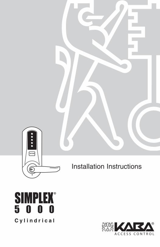
C y l i n d r i c a l
SIMPLEX5 0 0 0
®
Installation Instructions

TABLE OF CONTENTS
Exploded Install Parts 1
Tools Required 1
A. Door Preparation 2
B. Lock Handing 3
C. Door Thickness 3
D. Installing The Passage Set 4
E. Installing Outside Unit Assembly 5
F. Installing Inside Unit Assembly 5-6
G. Installing The Inside Lever / Knob 6
H. Changing Key-In-Lever / Knob (KIL / KIK) Cylinder 7-8
I. Installing / Removing Outside Lever / Knob 8-9(KIL / KIK models only)
J. Installing / Removing Outside Lever / Knob 9-10 (Interchangeable / Removable Core models)
K. Testing The Operation Of The Lock 10-11
L. Installing The Strike 11
M. Changing Combinations 12-13
N. Installing Rubber Bumpers 14
O. How To Reset A Lost Or Unknown Combination 15-18
P. Trouble Shooting 19
Notes 20-21
1) 2) 3)
WarningThe combination of this lock has been factory preset; 2 and 4 depressed at the same time, then 3 and thenENTER. For your security, the combination must be changed at time of installation.
OPERATION

1
TOOLS REQUIRED• Safety glasses• Electric drill (variable speed)• Awl or center punch• 21⁄8" (54 mm) hole saw pilot drill• 1" (25 mm) hole saw pilot drill
• 1⁄4" (7 mm) drill bit• 1" (25 mm) wood chisel• Hammer• Phillips head screw driver• Small flat blade screwdriver
Inside LeverMounting Screws
Inside UnitAssembly
Outside UnitAssembly
Outside LeverAssembly
3/4" (18mm) Screws
Latch
1" (25mm) Screws
Allen Wrench
Set Screw
ASA Strike
Release/Combination Change Tool
Model 5021
The Simplex 5000 (Model 5021 shown above) is a non-handed lock that ispreassembled for left-hand installations. It is field reversible.
For technical assistance please call1-800-849-TECH (8324) or 336-725-1331
Warnings and CautionsImportant: Carefully inspect windows, doorframe, door, lights, etc. to ensurethat the recommended procedures will not cause damage. Kaba AccessControl’s warranty does not cover damages caused by installation.
Caution: Wear safety glasses when preparing door.

A. DOOR PREPARATION
A-1 Place paper template (supplied) onto doorand mark for holes. Drill the four 1⁄4" (7 mm)holes first. Next drill the 21⁄8" (54 mm) crossbore hole. Drill the 1" (25 mm) hole last.
A-2 For Models 5041 & 5051 only. Wheninstalling Model 5021, skip to step A-4.Passage feature models require an additional1” (25 mm) hole in the door face (see “a” inthe illustration to the right).
A-3 For Models 5031 & 5051 only. When installing Models 5021 or 5041models, skip to step A-4. Inside code change models require an additional 1” (25 mm) hole in the door face (see “b” in the illustration above).
A-4 Mortise door edge for latch unit faceplate (c)1⁄8" (3 mm) deep to dimensions shown. Insertlatch unit into the 1" (25 mm) hole, makingcertain that the latch bolt bevel faces directionof closing door.
A-5 Secure the latch to the door using two 3⁄4" (19mm) combination screws (d) supplied. Latchunit faceplate must be flush with door (e).
2
4 x 1⁄4"
b 1"(for models5031 & 5051)a 1"
(for models5041 & 5051)
b 1"(for models5031 & 5051)
b 1"(for models5031 & 5051)
a 1"(for models5041 & 5051)
a 1"(for models5041 & 5051)
21⁄8"
1"
11⁄8"
c
e
d
21⁄4"

3
C. DOOR THICKNESSThe Simplex 5000 lock is preassembled to accommodate standard doorthickness 15⁄8" (41 mm) to 2" (51 mm).
C-1 (Reference Figure A) For thinner door applications of 13/8" (35 mm) to 11/2" (38 mm)Remove and discard the two connecting screws (a) from the cylindrical drive unit (b). Remove and discard the spacer (c). Remount the cylindrical drive unit using the two shorter 13/8" (35 mm) connecting screws supplied.
C-2 (Reference Figure B) For thicker door applications of 21/8" (54mm) to 21/4" (57mm)Remove the two connecting screws (a) from thecylindrical drive unit (b). Add the extra spacer(c) supplied. Remount the cylindrical drive unitusing the same two connecting screws (a) just removed. (Do not over tighten screws)
B. LOCK HANDINGThe Simplex 5000 is a non-handed lock that is preassembled for left-handdoor installations.
B-1 Determine the hand of your door. For left hand doors, proceed to Section C. For right hand doors, follow steps in B-2.
B-2 Remove the two connecting screws (a) from the cylindrical drive unit (b). Rotate cylindrical drive unit 180 degrees. Reposition spacer (c) as found before disassembly. Remount drive unit with the two connecting screws.
Left Hand Left Hand Reverse Bevel
LEFT HAND DOOR
Right Hand Right Hand Reverse Bevel
RIGHT HAND DOOR
b
b
b
a
a
a
c
c
c

4
D. INSTALLING THE PASSAGE SETFor models 5041 & 5051 only. When installing non-passage models, skip to section E.
D-1 Note: The end user may choose either a key cylinder (a) or turn knob (b) actuator to engage the passage function.
Prior to installing the passage actuator, holdthe chosen actuator housing in one hand, andwith the other hand, rotate the key cylinder orknob counterclockwise until it stops. If the keycylinder actuator is used, withdraw the key,which will lock the cylinder in this position (adetent in the turn knob locks the cylinder).
D-2 Insert the key cylinder or turn knob assembly (a or b)into the opening on the inside unit assembly (c). Upon completion, the arrow of the turn knob should be pointing to the left, or the dot on the face of the key cylinder actuator should be on the left.
D-3 Secure the passage set assembly with the spring clip (d) from the inside.
D-4 Rotate the knob or key cylinder (re-insert key at this point) clockwise to test the rotation. If properly installed, the knob or key cylinder should rotate 90 degrees clockwise so that the arrow (knob) is pointing up or the dot (key cylinder) is at the top.
Note: Leave the actuator set in this position for installation (if key cylinder is used, remove the key at this point).
D-5 Note: The tailpiece of the passage actuator is scored on several places to allow you to easily break off the section that extends beyond the required length to engage the passage set cam.
Hold the tailpiece firmly with a pair of pliers, adjacent to the desired break line. With a second pair of pliers, grip the tailpiece on the other side of the scored line and bend up and down until it breaks.
c
bd
a

5
E. INSTALLING OUTSIDE UNIT ASSEMBLY
Note: Installing levers/knobs to the unit assemblies before mounting the unit assemblies may ease initial installation.
E-1 For models 5041 & 5051 only. When installing non-passage models, skip to step E-2. Ensure that thepassage cam (b) is rotated counterclockwise until it stops. When complete, the slot will be vertical.
E-2 Slide the drive unit (a) into 21⁄8" (54 mm) cross bore hole by depressing latch bolt (b) in slightly until the outside unit assembly (c) rests flush against the door.
E-3 The drive unit (d) must engage the latch unit prongs(e) and the shoe retractor (f) must engage the latchunit tailpiece (g) as shown.
F. INSTALLING INSIDE UNIT ASSEMBLY
Note: Installing levers/knobs to the unit assemblies before mounting the unit assemblies may ease initial installation.
F-1 For Models 5041 & 5051 only. When installing non-passage models, skip to step F-2. Slide the drive hub (a) into the sleeve (b), and the passage tailpiece (d) into the passage cam slot until the inside unit assembly (c) rests flush against the door.
F-2 Slide the drive hub (a) into the drive sleeve (b) until the inside unit assembly (c) rests flush against the door.
b
a
b
f
g
e
d
c
c
d
a
a
b
b
c

F-3 For standard door thickness 15⁄8" (41 mm) to 2" (51 mm), secure the outside and inside unit assemblies to the door by using four 27⁄8" (73 mm) screws (d) (supplied) in all four holes as indicated.
For thinner door 13⁄8" (35 mm) to 11⁄2" (38 mm),secure the outside and inside unit assemblies to the door by using four 2 1⁄2" (64 mm) screws (e) (supplied) in all four holes as indicated.
For thicker door 2 1⁄8" (54 mm) to 21⁄4" (57 mm),secure the outside and inside unit assemblies to thedoor by using four 31⁄4" (82mm) screws (f) (supplied)in all four holes as indicated.
G. INSTALLING THE INSIDE LEVER/KNOB
Note: Installing the lever/knob assemblies to the unit beforemounting the unit assemblies, may ease initial installation.
G-1 Insert the inside lever/knob (a) onto the unit assembly.Secure the inside lever/knob with the 3/8 in (5mm) hexscrew (b) supplied using the allen wrench (c) supplied.
6
d, e, f
a
a
b
b
c
c

H. CHANGING KEY-IN-LEVER/KNOB CYLINDERThe Simplex 5000 outside lever/knob comes preassembled with Kaba's key-in-lever/knob cylinder (Kaba 1599). To use a different key-in-lever/knob cylinder, follow the remaining steps in this section.
H-1 Remove KIL/KIK cylinder (a) from theoutside lever/knob (b) by removing thelever insert (e) (no insert on knob).Remove the rubber cylinder retainer (c)using a small screwdriver or needle nosepliers.
H-2 Determine the proper tailpiece (d) neededfor your KIL/KIK cylinder from the chartabove.
You must use a KABA tailpiece. The K-2tailpiece is preassembled with the 1599cylinder.
7
Assa 65611, Australian: Kaba experT 107K5 &Boyd KC286, Corbin-Russwin 2000-03, Kaba1599, Schlage 23-001, Schlage Primus 20-760,Kaba Peaks 1099
Medeco 20W200H1
Arrow C100, Sargent 10 LINE
Marks
Abloy 5277, Abloy 5477, Assa 65691, Kaba 15396, Kaba Gemini 4730
KIL/KIK CYLINDERTAILPIECE
K1
K3
K2
K4
K5
b
b
a
a
e
d
d
c
c

8
H-3 Assemble the required tailpiece (d) supplied withyour KIL/KIK cylinder. All tailpieces must beinstalled vertically as shown for proper installation.
H-4 Insert the KIL/KIK cylinder (a) into the outsidelever/knob (b) and secure it with the cylinderretainer (c) and lever insert (e) (no insert onthe knob). The KIL/KIK cylinder should besnug and unable to move freely.
I. INSTALLING/REMOVING OUTSIDE LEVER/KNOB(Key-in-Lever/Knob Models only) (For interchangeable and removablecores, proceed to section J)
Note: Installing lever/knob to the unit assemblies before mounting the unit assemblies, may ease initial installation.
I-1 Make certain the lever catch is up as shown (c). The lever catch should be flush around the outer diameter of the outside driver. Make certain the lever sleeve (f) is rotated to properly mate with the outside lever/knob.
I-2 Insert one of the supplied keys (a) into the outside lever/knob (b) and rotate key counterclockwise 45 degrees.
I-3 Insert the outside lever/knob (b) until it is flush to the outside unit assembly (levers fit closer than knobs). Secure the outside lever/knob by rotating the key clockwise 45 degrees to the horizontal position. Remove key.
KIL Lever SleeveLH RH
b
a
b
ce
a
b
a
b
a
45º
c
CorrectPosition Incorrect
Position
vertical
d
c
f
d
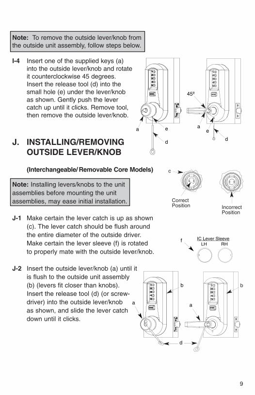
Note: To remove the outside lever/knob from the outside unit assembly, follow steps below.
I-4 Insert one of the supplied keys (a)into the outside lever/knob and rotateit counterclockwise 45 degrees.Insert the release tool (d) into thesmall hole (e) under the lever/knobas shown. Gently push the levercatch up until it clicks. Remove tool,then remove the outside lever/knob.
J. INSTALLING/REMOVINGOUTSIDE LEVER/KNOB
(Interchangeable/ Removable Core Models)
Note: Installing levers/knobs to the unit assemblies before mounting the unit assemblies, may ease initial installation.
J-1 Make certain the lever catch is up as shown (c). The lever catch should be flush around the entire diameter of the outside driver. Make certain the lever sleeve (f) is rotated to properly mate with the outside lever/knob.
J-2 Insert the outside lever/knob (a) until itis flush to the outside unit assembly(b) (levers fit closer than knobs). Insert the release tool (d) (or screw-driver) into the outside lever/knob as shown, and slide the lever catch down until it clicks.
9
IC Lever SleeveLH RH
e
d
b
d
aa
a
45º
ae
d
f
c
CorrectPosition Incorrect
Position
b

Kaba Access Control warrants this product to be free from defects in materialand workmanship under normal use and service for a period of three (3) years.Kaba Access Control will repair or replace, at our discretion, 5000 Series Locksfound by Kaba Access Control analysis to be defective during this period. Ouronly liability, whether in tort or in contract, under this warranty is to repair orreplace products that are returned to Kaba Access Control within the three (3)year warranty period.
This warranty is in lieu of and not in addition to any other warranty or condition,express or implied, including without limitation merchantability, fitness forpurpose or absence of latent defects.
ATTENTION: This warranty does not cover problems arising out of improperinstallation, neglect or misuse. All warranties implied or written will be null andvoid if the lock is not installed properly and / or if any supplied component part issubstituted with a foreign part. If the lock is used with a wall bumper, thewarranty is null and void. If a doorstop is required, we recommend the use of afloor secured stop.
The environment and conditions of use determine the life of finishes on Kaba Access Control products. Finishes on Kaba Access Control productsare subject to change due to wear and environmental corrosion. Kaba Access Control cannot be held responsible for the deterioration of finishes.
Authorization to Return GoodsReturned merchandise will not be accepted without prior approval. Approvalsand Returned Goods Authorization Numbers (RGA Numbers) for the 5000Series are available through our Customer Service department in Winston-Salem, NC (800) 849-8324. The serial number of a lock is required to obtainthis RGA Number. The issuance of an RGA does not imply that a credit orreplacement will be issued.
The RGA number must be included on the address label when material is returned to the factory. All component parts including latches and strikes (evenif not inoperative) must be included in the package with return. All merchandisemust be returned prepaid and properly packagedto the address indicated.
* Simplex 5000 locks are warranted three (3) years from date of purchase. E-Plex 5x00 locks are warranted three (3) years from date of activation.
KABA SIMPLEX®/E-PLEX™ 5x00 SERIESLIMITED WARRANTY

KA
BA
AC
CE
SS
CO
NT
RO
L29
41 IN
DIA
NA
AV
EN
UE
WIN
ST
ON
-SA
LEM
, NC
27
199-
3770
NO
PO
STA
GE
NE
CE
SS
AR
YIF
MA
ILE
DIN
TH
E
UN
ITE
D S
TAT
ES
BU
SIN
ES
S R
EP
LYM
AIL
FIR
ST-
CLA
SS
MA
ILP
ER
MIT
NO
. 156
3
PO
STA
GE
WIL
LB
E P
AID
BY
AD
DR
ES
SE
E
WIN
STO
N-S
ALE
M, N
C

Thank you for purchasing our product. In order to
protect your investment and to enable us to better
serve you in the future, please fill out this registrationcard and return it to K
aba Access C
ontrol, or register online at w
ww
.Kab
a-Ilco.co
m.
This lock will be used in w
hat type of facility?
❏C
omm
ercial Building
❏Industrial / M
anufacturing
❏C
ollege/U
niversity❏
Governm
ent/Military
❏S
chool/Educational
❏H
ospital/Healthcare
❏A
irport❏
Other (please specify)
What area is being secured w
ith this lock? (e.g. Front D
oor, Com
mon D
oor, Exercise R
oom)
This lock is:
❏R
eplacing a conventional❏
Replacing a S
implex
/Unican
/Kaba Ilco
/Kaba A
ccess keyed lock
Control M
echanical Pushbutton Lock (e.g.L1000)
❏R
eplacing another electronic keyless lock
How
did you learn about Kaba A
ccess Control P
ushbutton Locks?
❏A
dvertisement
❏P
revious Use
❏A
nother Use
❏Locksm
ith❏
Maintenance
❏O
ther (please specify)
What w
as your reason for buying this lock?
Who installed your lock?
❏Locksm
ith❏
Maintenance
❏O
ther
❏C
heck here if you would like m
ore information on K
aba Access C
ontrol locks.
Nam
e
Position
Com
pany
Address
City
State
ZIP
(Postal C
ode)C
ountry
Phone
Fax
Em
ail
Nam
e of Dealer P
urchased From
Date of P
urchase
Lock Model N
umber
Serial N
umber (on box label)
RE
GIS
TR
AT
ION
CA
RD
Notes

10
K. TESTING THE OPERATION OF THE LOCK
K-1 Rotate inside lever/knob and hold. Ensure that the latch is fully retracted andflush with the latch faceplate. Release the inside lever/knob; the latchshould be fully extended.
J-3 Insert the supplied tailpiece (e) with the flatinstalled vertically into the outside lever/knob(b) as shown. Make certain you rotate thetailpiece so that it aligns with the rear of the core. For screw cap type cylinders(Schlage) (g), the tailpiece must be assembled to the cylinder first, with thetailpiece vertically as shown. Insert the core into the outside lever/knob.
Notes: To remove the outside lever/knob from the outside unit assembly, follow the steps below.
J-4 Remove the interchangeable core (a). Then remove the tailpiece (b).
Note: You may want to use needle nose pliers for some tailpieces.
Insert the release tool (d) into the small hole (f) under thelever/knob as shown. Gently push lever/knob catch up until it clicks. Remove tool, thenremove outside lever/knob.
b a
a
f
d
vertical
g
e e
b
b
b
f
d

11
L. INSTALLING THE STRIKE
Note: The latch and strike provided must be used.
L-1 Mark location of strike on the door frame, making certain that the strike opening is aligned (a) with the latch bolt.
L-2 Mortise doorframe for strike 3⁄32" (3 mm) deep minimum to dimensions shown.Secure strike (b) to the door frame usingtwo 1" (25 mm) combination screws (c)(supplied).
K-2 For Models 5041 & 5051 only. When installing non-passage models,skip to step K-4. Ensure that the key cylinder or knob of the passageactuator is set so that the arrow or dot is at the top. Rotate outsidelever/knob and hold. Ensure that the latch is fully retracted and flush with thelatch faceplate. Release outside lever/knob: the latch should be fullyextended.
K-3 Rotate passage actuator counterclockwise so that the arrow or dot is to the left. Then rotate outside lever/knob. The latch should not move.
K-4 Enter the factory-set combination: Depress buttons 2 and 4 at the same time(& release), then depress button 3 (& release), then depress the “ENTER”button (& release). You should feel a slight click as each button isdepressed.
K-5 Rotate outside lever/knob and hold. Ensure that the latch is fully retracted andflush with the latch faceplate. Release the outside lever/knob; the latchshould be fully extended. Press the “ENTER” button and release, thenrotate outside lever/knob. The latch should NOT retract.
K-6 Insert one of the (supplied) keys into the outside lever/knob. Rotate key counterclockwise to stop position and hold. Ensure that the latch is fully retracted and flush with the latch faceplate. Rotate key clockwise to horizontalposition and remove key. The latch should be fully extended.
a
c
b
11⁄4" (31mm)
47⁄8" (124mm)
33⁄8" (84mm)

12
M. CHANGING COMBINATIONS
Note: The factory set combination of your new 5000 series: Press “2” and “4” atthe same time, then release. Press “3”, then release. Press the “ENTER” button,then release. For your security, the factory set combination MUST BEchanged when lock is installed.
The combination can be easily changed using one to five of the lock’s buttons inany order in the combination. Each button can only be used once. Note: Threeor more non-sequential button combinations are recommended for highersecurity. Also, two or more buttons may be pushed together (at the same time)as part of your new combination.
CAUTION: The door MUST BE open during this entire procedure.
M-1 Note: The combination change can be done without removing lock fromdoor. Ensure that the door is open during this procedure. Rotate theoutside lever/knob (d) once to stop position and release to reset the lock the latch should not retract.
M-2 Press the existing combination (b) followed by the ENTER button (c) and release; do not turn the lever/knob.
Note: Determine if you have an interior/exterior code change, and follow appropriate procedure below.
Exterior Combination Change
M-3 Insert the release tool (a) through hole in number pad and gently lift up loop end of the tool to depress the code change button until you hear a click; remove tool and do not pressany buttons (proceed to M-4).
a
b
cd
e

13
Interior Combination Change
M-3 Unscrew special torx screw from inside housingusing supplied torx wrench. Enter your existingcombination, and depress and release the“ENTER” button. Insert longer end of the sametorx wrench through the opening until it engageswith the mating part. Turn wrench counter-clockwise (using minimal force) approximately 90degrees, until it clicks. Return wrench to initialposition. Remove wrench and replace torx screw.
M-4 **This Step Is Very Important** Rotatelever/knob (d) once, and only once to clearthe old combination; the latch (e) will retract;release the lever/knob.
M-5 Press in your new combination (b) followed bythe ENTER button (c) and release.
M-6 Rotate the lever/knob (d) to verify that the latch (e) retracts confirming the validity of the new combination (if you try the old combination now, it should not work).
IMPORTANT: The “ENTER” button must be depressed and released afterentering the combination. The latch will not retract until the “ENTER”button is depressed and released.
COMBINATION SETTING RECORD
Combination & ENTER Date
& ENTER
& ENTER
& ENTER
& ENTER
& ENTER
& ENTER
& ENTER
& ENTER
b
cd
e

14
N. INSTALLING RUBBER BUMPERS
N-1 Close the door and apply pressure making sure the deadlatch (a) rests on the strike plate(b) as shown. Standing on the frame (door stop) side of the door, check for gaps betweenthe door and the frame on the three sides of the frame (left, right, and top).
N-2 Mark locations where the gaps are approximately 3⁄16" (5 mm). Make sure these locations are free from grease and dust. Peelthe bumpers (c) (supplied) from their protectivebacking without touching the adhesive surfaceand stick them on the marked locations. Note: Allow 24 hours for adhesive to set before testing. The door may be operated normally during this time.
For technical assistance please call1-800-849-TECH (8324) or 336-725-1331
a b
c
Caution: Check the operation of the latch by making sure that thedeadlatch (a) stops against the strike (b) as shown and does not slide intothe strike opening when the door is closed. If that situation occurs, then atotal lockout may occur. This will cancel our warranty of the complete lockmechanism. If necessary, correct the door over-travel by using the rubberbumpers as described in Section N (Installing Rubber Bumpers).
Correct
Incorrect a b
15
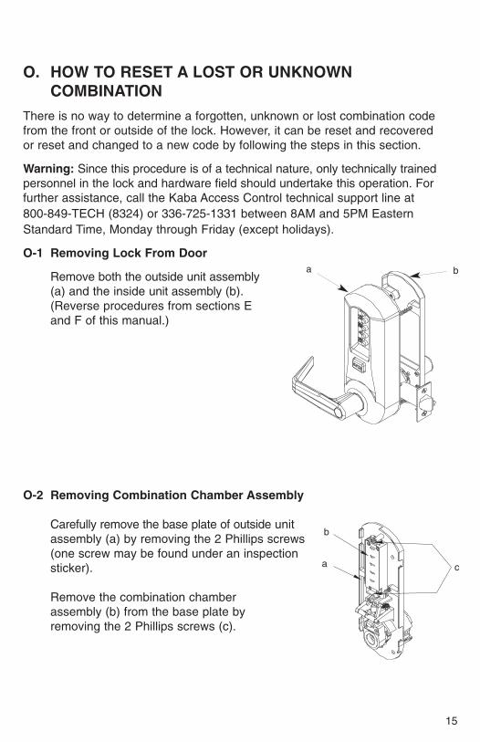
O. HOW TO RESET A LOST OR UNKNOWN COMBINATION
There is no way to determine a forgotten, unknown or lost combination codefrom the front or outside of the lock. However, it can be reset and recovered or reset and changed to a new code by following the steps in this section.
Warning: Since this procedure is of a technical nature, only technically trainedpersonnel in the lock and hardware field should undertake this operation. Forfurther assistance, call the Kaba Access Control technical support line at 800-849-TECH (8324) or 336-725-1331 between 8AM and 5PM EasternStandard Time, Monday through Friday (except holidays).
O-1 Removing Lock From Door
Remove both the outside unit assembly(a) and the inside unit assembly (b). (Reverse procedures from sections E and F of this manual.)
O-2 Removing Combination Chamber Assembly
Carefully remove the base plate of outside unitassembly (a) by removing the 2 Phillips screws(one screw may be found under an inspectionsticker).
Remove the combination chamber assembly (b) from the base plate by removing the 2 Phillips screws (c).
a b
c
b
a

16
Remove the 3-sided dust cover (d) to fully expose the chamber by removing 2 small Phillips screws (e). (May be 1 screw (x) in newer models)
O-3 Resetting and Recovery of Current Code
To reset the code gears (a), each one of the 5 “L” shaped legs (b) of the unlocking slide (c) must engage snugly with the corresponding code gear pocket (d) next to it.
Position the chamber in one hand, as shown. Holdchamber by the top screw tab (e) and bottom screw tab (f).
Rotate the reset cam (g) back toward you with yourfinger, towards the key stems (h) as far as it will goand then release. Now look at the code gears (a)and the unlocking slide (c). Note that some or all 5 ofthe code gear pockets (d) are rotated away from the“L” shaped legs (b) as if out of alignment. Typicallyeach code gear pocket will be at a slightly differentdistance compared to the other.
ed
(x)
a
c
j
j
g
h
ei
a
c
f
b
d

17
Note: Sometimes two different gear pockets are away from alignment byexactly the same distance – this indicates that the current code uses twodifferent number buttons (example, 2 and 4) depressed at the sametime as part of the code combination.
Using a small flat blade screw driver or your thumbnail, depress the keystem which corresponds to the gear pocket which has been rotated the farthest away (out of alignment) from the “L” shaped leg. When depressed,the key stem(s) should stay down and the corresponding gear pocket(s) should move closer to its corresponding “L” leg, closer to alignment. Record the key stem number. This is the first number of your combination.
Note: If two gear pockets are at the same distance, depress both of these corresponding key stems at the same time.
Continue by pressing the key stem that corresponds to the gear pocket that was the next furthest away (do not include gear pockets that have already been rotated). Record each key stem number that is depressed. Continue this procedure until all five gear pockets are aligned with their corresponding “L” shaped legs on the unlocking slide. The combination is therecorded numbers, in the order recorded.
Note: If you depress the wrong key stem by mistake, rotate the reset camback toward you, (toward the key stems and release). This resets the codegears and you must repeat the above procedure, O-3.
O-4 Clearing the Current Code and Setting a New Code
Note: Align the code gear pockets with the “L” shaped legs.
Depress the code change button (i) located on top of the combination chamber once and release.
Rotate the reset cam back toward you with your finger (toward the key stems) as far as it will go and release.
Enter your new combination code by depressing the key stem corresponding to the first number (1 through 5) of your code. For example, if the new code is 3-2-5, then you would depress 3 first, then 2 and finally 5. Record this new combination code for future reference.
j
g
h
ei
a
c
f

18
Push the shoulder (j) at the bottom of the Unlocking slide up toward the code change button and release. If each of the 5 “L” shaped legs of the unlocking slide engages snugly inside its corresponding code gear pocket, then it confirms that the new code has been successfully changed. Rotate thereset cam (g) back toward you and release.
Note: If all 5 “L” shaped legs do not align fully with their corresponding code gear pockets, repeat the procedures O-3 and O-4.
O-5 Reinstalling chamber assembly into lock and retestingReinstall the 3-sided dust cover over the combination chamber with the 2 small Phillips screws removed. (May be 1 screw in newer models)
Reinstall the combination chamber assembly to the base plate with the 2 Phillips screws removed.
Reinstall the base plate on to the outside lock assembly with the 2 Phillipsscrews removed. Make sure all parts have been reinstalled correctly.
O-6 Reinstall lock on door by following the procedures in Sections E and F ofthis manual.
O-7 Retest new code with lock on door by entering the new numbers followedby the “ENTER” button and rotating the outside lever/knob. The lock shouldopen and the latch should retract.
For technical assistance please call1-800-849-TECH (8324) or 336-725-1331

19
P. TROUBLE SHOOTING
SYMPTOM POSSIBLE CAUSE REMEDY
1. The outside lever/knob
always retracts the latch
after depressing and
releasing the “ENTER”
button only (without
combination).
2. The outside lever/knob
will not go completely
inside the outside lock
assembly.
3. Correct combination is
depressed but the latch
does not retract.
4. Cannot remove key
from outside lever/knob
— key is stuck.
Lock is in “ZERO”
combination.
Lever catch is
misaligned.
Failed to depress the
“ENTER” button.
Key was rotated 180
degrees in wrong
direction.
Follow the procedure for
Changing Combinations
(Section M) except omit steps
1 and 2 (do not enter the
existing combination).
Insert release tool through
small hole on the outside unit
assembly (under the lever/
knob). Using the tool, gently
push lever catch up until it
clicks. Refer to Section I or J
(Installing and Removing the
Outside Lever/knob).
Always depress and release
the “ENTER” button after
depressing the correct
combination.
Rotate key counterclockwise.
Insert release tool through
small hole on the outside unit
assembly (under the lever/
knob). Using the tool
gently push lever catch up
until it clicks. Remove outside
lever/knob. Remove key.
Then follow steps in Section I
or J: Installing and Removing
the Outside Lever/Knob.

20
Notes

21
Notes

Kaba Access Control2941 Indiana Avenue Winston-Salem, NC 27105 USA
Tel: (800) 849-8324 (336) 725-1331Fax: (800) 346-9640 (336) 725-3269
www.kaba-ilco.com PKG-2842 1005