6.6.13a EGR Cooler Removal (Bellows System). Install new seal ring and water pump elbow on water...
18
SERIES 60 SERVICE MANUAL 6.6.13a EGR Cooler Removal (Bellows System) For Series 60 EGR equipped engines built after April 15, 2004 use the following procedures. PERSONAL INJURY To avoid injury from hot surfaces, wear protective gloves, or allow engine to cool before removing any component. 1. Remove two bolts and seal ring from water pump outlet elbow. Discard seal ring. 2. Remove water pump outlet elbow from hose on EGR cooler water inlet. 3. Remove hose and clamps from EGR Cooler water inlet. 4. Slide clamp onto hose of oil cooler water inlet. All information subject to change without notice. (Rev. 2004) 6SE483 0401 Copyright © 2004 DETROIT DIESEL CORPORATION From Bulletin 2-60-04 6-62a
Transcript of 6.6.13a EGR Cooler Removal (Bellows System). Install new seal ring and water pump elbow on water...

SERIES 60 SERVICE MANUAL
6.6.13a EGR Cooler Removal (Bellows System)
For Series 60 EGR equipped engines built after April 15, 2004 use the following procedures.
PERSONAL INJURY
To avoid injury from hot surfaces, wear protective gloves,or allow engine to cool before removing any component.
1. Remove two bolts and seal ring from water pump outlet elbow. Discard seal ring.
2. Remove water pump outlet elbow from hose on EGR cooler water inlet.
3. Remove hose and clamps from EGR Cooler water inlet.
4. Slide clamp onto hose of oil cooler water inlet.
All information subject to change without notice. (Rev. 2004)
6SE483 0401 Copyright © 2004 DETROIT DIESEL CORPORATION From Bulletin 2-60-04 6-62a

6.6 TURBOCHARGER (DIESEL)
5. Remove two clamps from bellows. See Figure 6-39a.
1. EGR Cooler 7. Exhaust Manifold End Section
2. EGR Actuator Assembly 8. Exhaust Manifold Center Section
3. Clamp 9. Exhaust Manifold End Section
4. Upper Hot Pipe 10. Bellows
5. Gasket 11. EGR Valve Assembly
6. Stud 12. Gasket
Figure 6-39a EGR System and Related Parts
(Rev. 2004) All information subject to change without notice.
6-62b From Bulletin 2-60-04 6SE483 0401 Copyright © 2004 DETROIT DIESEL CORPORATION
SERIES 60 SERVICE MANUAL
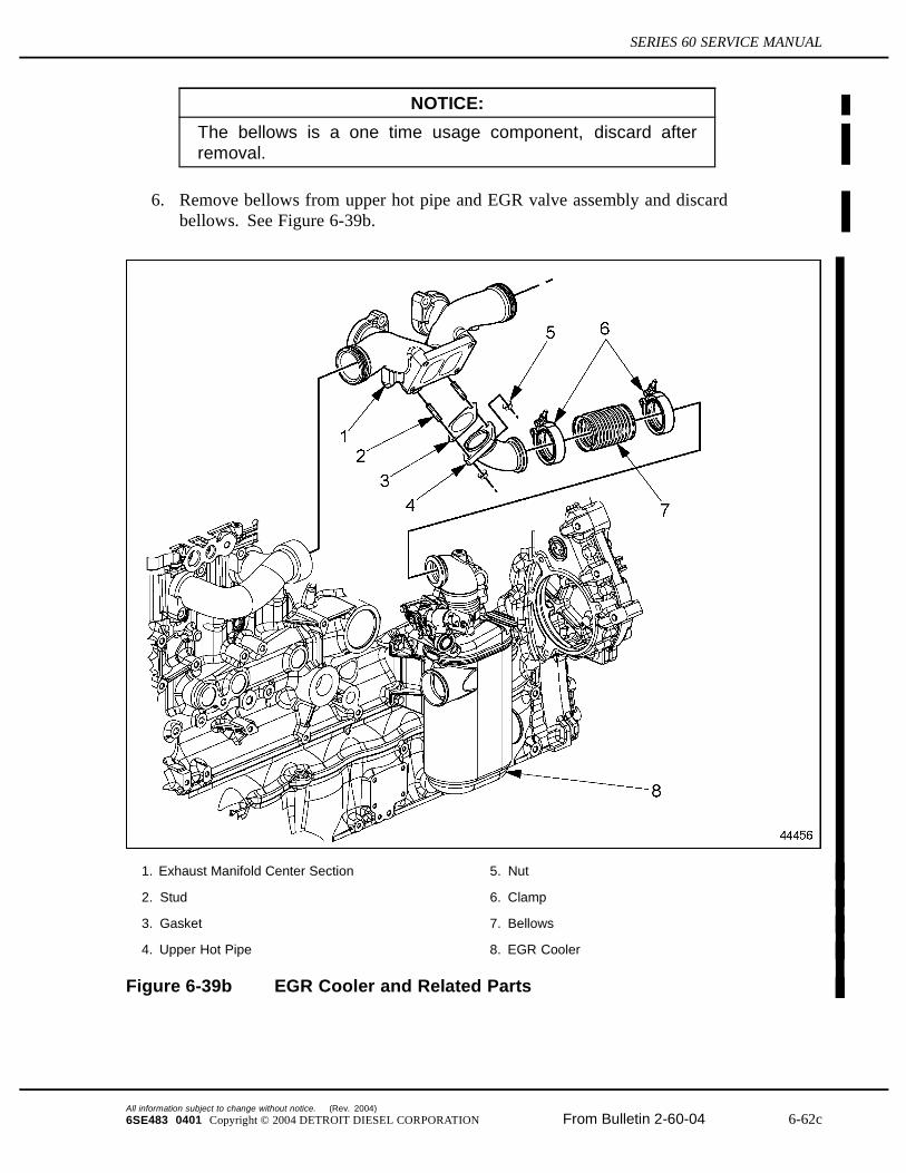
NOTICE:
The bellows is a one time usage component, discard afterremoval.
6. Remove bellows from upper hot pipe and EGR valve assembly and discardbellows. See Figure 6-39b.
1. Exhaust Manifold Center Section 5. Nut
2. Stud 6. Clamp
3. Gasket 7. Bellows
4. Upper Hot Pipe 8. EGR Cooler
Figure 6-39b EGR Cooler and Related Parts
All information subject to change without notice. (Rev. 2004)
6SE483 0401 Copyright © 2004 DETROIT DIESEL CORPORATION From Bulletin 2-60-04 6-62c
6.6 TURBOCHARGER (DIESEL)
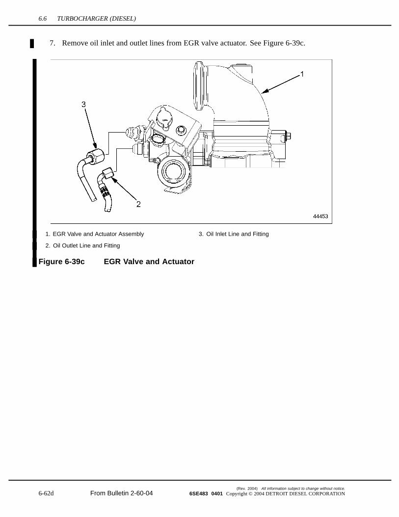
7. Remove oil inlet and outlet lines from EGR valve actuator. See Figure 6-39c.
1. EGR Valve and Actuator Assembly 3. Oil Inlet Line and Fitting
2. Oil Outlet Line and Fitting
Figure 6-39c EGR Valve and Actuator
(Rev. 2004) All information subject to change without notice.
6-62d From Bulletin 2-60-04 6SE483 0401 Copyright © 2004 DETROIT DIESEL CORPORATION
SERIES 60 SERVICE MANUAL
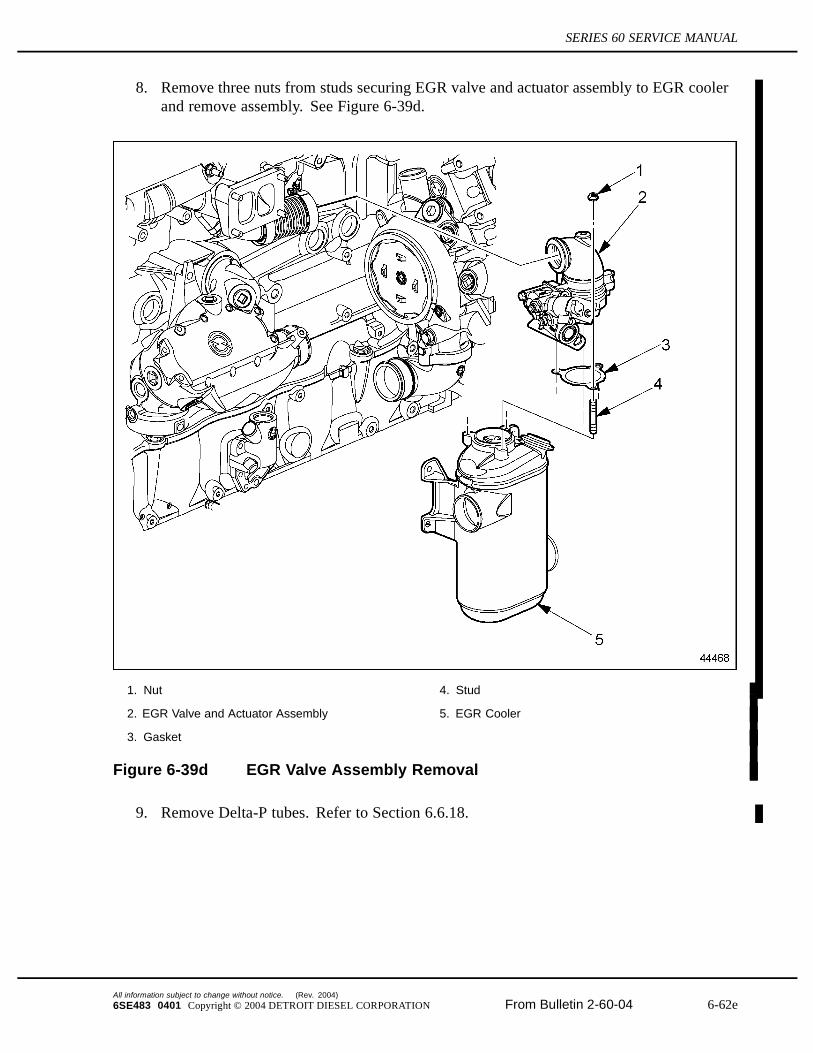
8. Remove three nuts from studs securing EGR valve and actuator assembly to EGR coolerand remove assembly. See Figure 6-39d.
1. Nut 4. Stud
2. EGR Valve and Actuator Assembly 5. EGR Cooler
3. Gasket
Figure 6-39d EGR Valve Assembly Removal
9. Remove Delta-P tubes. Refer to Section 6.6.18.
All information subject to change without notice. (Rev. 2004)
6SE483 0401 Copyright © 2004 DETROIT DIESEL CORPORATION From Bulletin 2-60-04 6-62e

6.6 TURBOCHARGER (DIESEL)
10. Remove delivery pipe clamp from EGR Cooler outlet and remove deliverypipe. Refer to Section 6.6.14. See Figure 6-39e.
1. Clamp 3. EGR Cooler
2. Delivery Pipe
Figure 6-39e EGR Cooler and Delivery Pipe
PERSONAL INJURY
To avoid injury when removing or installing a heavy enginecomponent, ensure the component is properly supportedand securely attached to an adequate lifting device toprevent the component from falling.
11. Remove four bolts attaching EGR Cooler backplate to engine block.
12. Remove hose and clamp from oil cooler water inlet.
6.6.13b EGR Cooler Installation (Bellows System)
Series 60 engines equipped with EGR systems have a EGR Cooler which cools the exhaust gasprior to introduction in the Intake Manifold.
Install the EGR Cooler as follows:
1. Install EGR water outlet hose and clamps onto oil cooler. See Figure 6-39f.
(Rev. 2004) All information subject to change without notice.
6-62f From Bulletin 2-60-04 6SE483 0401 Copyright © 2004 DETROIT DIESEL CORPORATION

SERIES 60 SERVICE MANUAL
PERSONAL INJURY
To avoid injury when removing or installing a heavy enginecomponent, ensure the component is properly supportedand securely attached to an adequate lifting device toprevent the component from falling.
2. Insert EGR Cooler water outlet into hose on oil cooler inlet. Secure hose with clamps.
3. Align EGR Cooler back plate holes with four bosses on cylinder block.
4. Thread four M10 bolts through back plate and into cylinder block.
5. Tighten bolts to 46-52 N·m (34-38 lb·ft).
All information subject to change without notice. (Rev. 2004)
6SE483 0401 Copyright © 2004 DETROIT DIESEL CORPORATION From Bulletin 2-60-04 6-62g

6.6 TURBOCHARGER (DIESEL)
6. Install hose and clamps onto EGR Cooler water inlet. See Figure 6-39f.
1. Bolt 3. Clamp
2. Hose 4. EGR Cooler
Figure 6-39f EGR Cooler and Related Parts
7. Insert water pump outlet elbow into hose on EGR cooler water inlet. Secure hose withclamps
8. Install new seal ring and water pump elbow on water pump and secure with two M10bolts. Torque bolts to 58-73 N·m (43-54 lb·ft).
9. Install delivery pipe. Refer to section 6.6.17.
(Rev. 2004) All information subject to change without notice.
6-62h From Bulletin 2-60-04 6SE483 0401 Copyright © 2004 DETROIT DIESEL CORPORATION

SERIES 60 SERVICE MANUAL
6.6.13c Upper Hot Pipe, Bellows and EGR Valve Removal
For Series 60 Engines equipped EGR systems remove upper hot pipe, bellows and EGR Valveas follows:
PERSONAL INJURY
To avoid injury from hot surfaces, wear protective gloves,or allow engine to cool before removing any component.
All information subject to change without notice. (Rev. 2004)
6SE483 0401 Copyright © 2004 DETROIT DIESEL CORPORATION From Bulletin 2-60-04 6-62i
6.6 TURBOCHARGER (DIESEL)
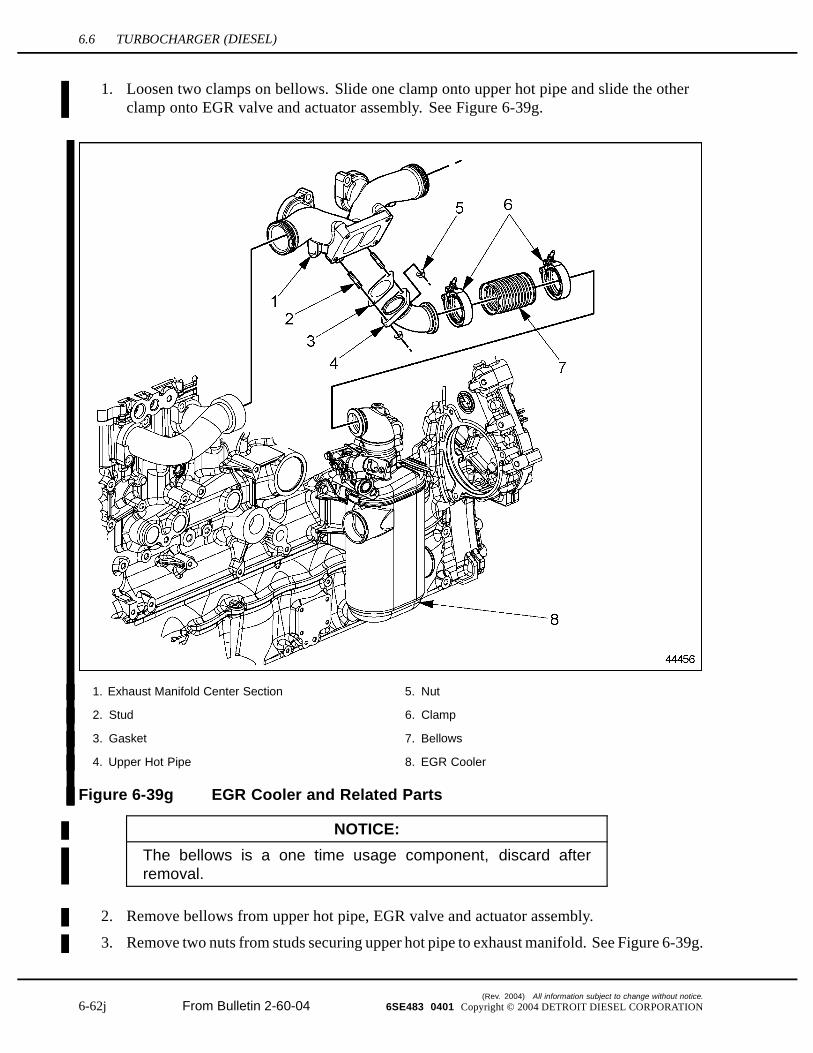
1. Loosen two clamps on bellows. Slide one clamp onto upper hot pipe and slide the otherclamp onto EGR valve and actuator assembly. See Figure 6-39g.
1. Exhaust Manifold Center Section 5. Nut
2. Stud 6. Clamp
3. Gasket 7. Bellows
4. Upper Hot Pipe 8. EGR Cooler
Figure 6-39g EGR Cooler and Related Parts
NOTICE:
The bellows is a one time usage component, discard afterremoval.
2. Remove bellows from upper hot pipe, EGR valve and actuator assembly.
3. Remove two nuts from studs securing upper hot pipe to exhaust manifold. See Figure 6-39g.
(Rev. 2004) All information subject to change without notice.
6-62j From Bulletin 2-60-04 6SE483 0401 Copyright © 2004 DETROIT DIESEL CORPORATION
SERIES 60 SERVICE MANUAL
4. Remove upper hot pipe and gasket from exhaust manifold. Discard gasket.
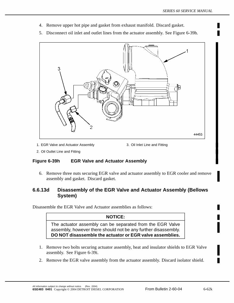
5. Disconnect oil inlet and outlet lines from the actuator assembly. See Figure 6-39h.
1. EGR Valve and Actuator Assembly 3. Oil Inlet Line and Fitting
2. Oil Outlet Line and Fitting
Figure 6-39h EGR Valve and Actuator Assembly
6. Remove three nuts securing EGR valve and actuator assembly to EGR cooler and removeassembly and gasket. Discard gasket.
6.6.13d Disassembly of the EGR Valve and Actuator Assembly (BellowsSystem)
Disassemble the EGR Valve and Actuator assemblies as follows:
NOTICE:
The actuator assembly can be separated from the EGR Valveassembly, however there should not be any further disassembly.DO NOT disassemble the actuator or EGR valve assemblies.
1. Remove two bolts securing actuator assembly, heat and insulator shields to EGR Valveassembly. See Figure 6-39i.
2. Remove the EGR valve assembly from the actuator assembly. Discard isolator shield.
All information subject to change without notice. (Rev. 2004)
6SE483 0401 Copyright © 2004 DETROIT DIESEL CORPORATION From Bulletin 2-60-04 6-62k

6.6 TURBOCHARGER (DIESEL)
6.6.13d.1 Cleaning of the EGR Valve and Actuator Assembly (BellowsSystem)
Clean the internal spline drive on the actuator assembly and external spline on the valve shaftas follows:
1. Brush splines to loosen debris. See Figure 6-39i.
EYE INJURY
To avoid injury from flying debris when using compressedair, wear adequate eye protection (face shield or safetygoggles) and do not exceed 40 psi (276 kPa) air pressure.
2. Remove any loose debris with compressed air.
6.6.13d.2 Inspection of the EGR Valve and Actuator Assembly (BellowsSystem)
Inspect the EGR Valve and Actuator Assembly as follows:
1. Visually inspect actuator and valve assemblies for excessive wear.
2. If the EGR valve or actuator assembly are defective replace with a new assembly.
3. If the EGR valve or actuator assembly are not defective reuse the assembly.
6.6.13e Assembly of the EGR Valve and Actuator Assemblies (BellowsSystem)
Assemble the EGR valve and actuator as follows:
NOTICE:
The insulator shield must be replaced whenever the actuatorassembly is disassembled from the EGR valve assembly. Theheat shield can be reused.
NOTE:The spline drive for the actuator assembly is keyed to ensure proper alignment withthe shaft on the valve assembly.
(Rev. 2004) All information subject to change without notice.
6-62l From Bulletin 2-60-04 6SE483 0401 Copyright © 2004 DETROIT DIESEL CORPORATION
SERIES 60 SERVICE MANUAL
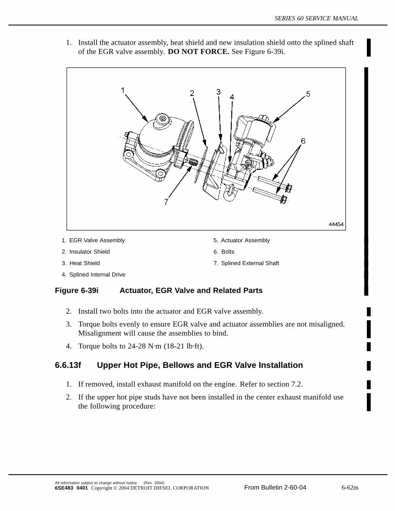
1. Install the actuator assembly, heat shield and new insulation shield onto the splined shaftof the EGR valve assembly. DO NOT FORCE. See Figure 6-39i.
1. EGR Valve Assembly 5. Actuator Assembly
2. Insulator Shield 6. Bolts
3. Heat Shield 7. Splined External Shaft
4. Splined Internal Drive
Figure 6-39i Actuator, EGR Valve and Related Parts
2. Install two bolts into the actuator and EGR valve assembly.
3. Torque bolts evenly to ensure EGR valve and actuator assemblies are not misaligned.Misalignment will cause the assemblies to bind.
4. Torque bolts to 24-28 N·m (18-21 lb·ft).
6.6.13f Upper Hot Pipe, Bellows and EGR Valve Installation
1. If removed, install exhaust manifold on the engine. Refer to section 7.2.
2. If the upper hot pipe studs have not been installed in the center exhaust manifold usethe following procedure:
All information subject to change without notice. (Rev. 2004)
6SE483 0401 Copyright © 2004 DETROIT DIESEL CORPORATION From Bulletin 2-60-04 6-62m

6.6 TURBOCHARGER (DIESEL)
NOTICE:
Do not apply lubricant to studs.
[a] Install two M8 studs into the threaded holes near the EGR port on the bottom of theexhaust manifold center section for the turbocharger.
[b] Torque studs to 28-32 N·m (21-24 lb·ft).
[c] Install four M10 studs into the threaded holes on the exhaust manifold center sectionfor the turbocharger.
[d] Torque M10 studs to 20-24 N·m (15-18 lb·ft).
3. If the EGR cooler studs have not been installed in the cooler use the following procedure:
[a] Install three M8 studs into the threaded holes on the EGR cooler.
[b] Torque studs to 28-32 N·m (21-24 lb·ft).
4. If the upper hot pipe and gasket have not been installed use the following procedure:
[a] Install gasket and upper hot pipe onto studs on exhaust manifold center section.
[b] Install two nuts on studs and torque to 22-26 N·m (16-19 lb·ft).
5. Loosely install the bellows to the EGR valve assembly using a bellows clamp.
6. Slip the remaining bellows clamp over the flange of the upper hot pipe.
7. Install the EGR cooler gasket.
8. Align the bellows with the upper hot pipe and while pressing against the upper hot pipe,lower the EGR valve assembly onto the EGR cooler studs.
9. Tighten three EGR cooler nuts to 22-26 N·m (16-19 lb·ft).
(Rev. 2004) All information subject to change without notice.
6-62n From Bulletin 2-60-04 6SE483 0401 Copyright © 2004 DETROIT DIESEL CORPORATION
SERIES 60 SERVICE MANUAL
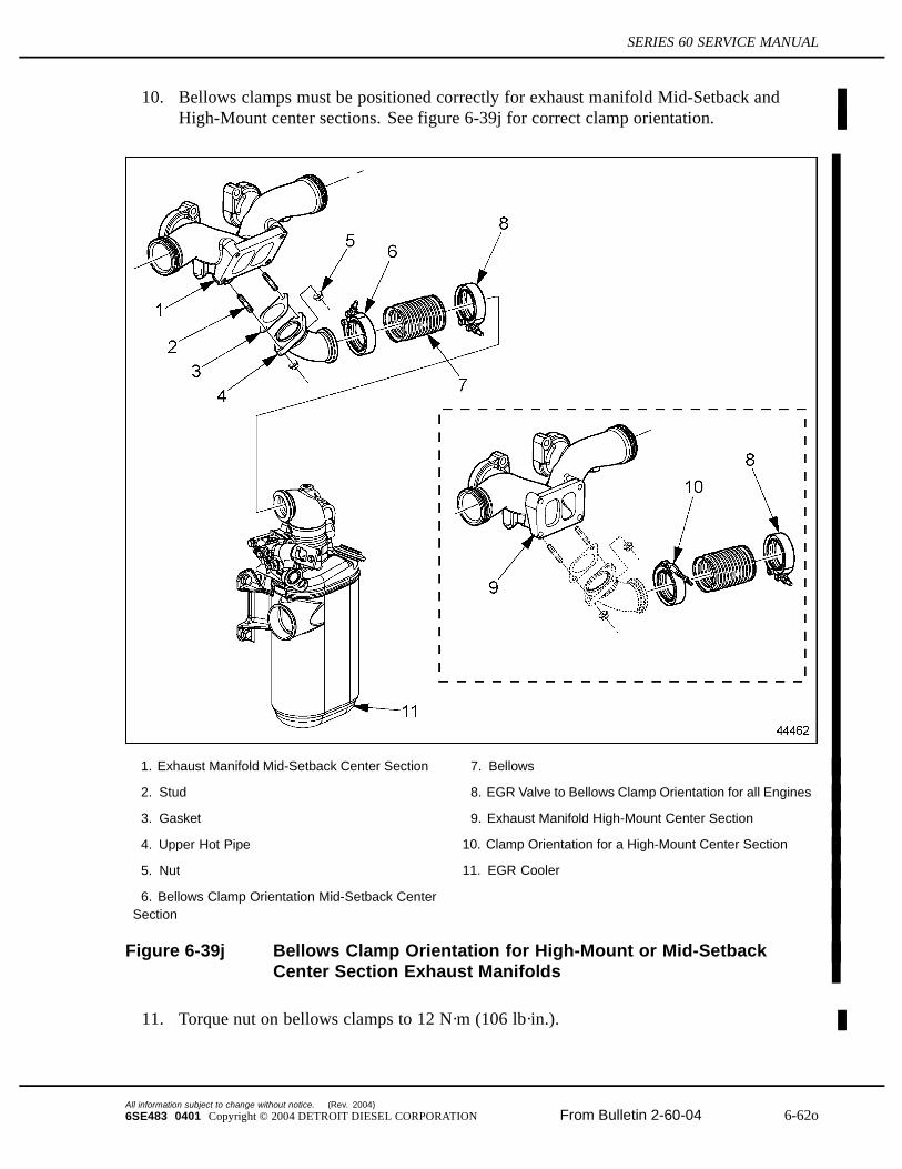
10. Bellows clamps must be positioned correctly for exhaust manifold Mid-Setback andHigh-Mount center sections. See figure 6-39j for correct clamp orientation.
1. Exhaust Manifold Mid-Setback Center Section 7. Bellows
2. Stud 8. EGR Valve to Bellows Clamp Orientation for all Engines
3. Gasket 9. Exhaust Manifold High-Mount Center Section
4. Upper Hot Pipe 10. Clamp Orientation for a High-Mount Center Section
5. Nut 11. EGR Cooler
6. Bellows Clamp Orientation Mid-Setback CenterSection
Figure 6-39j Bellows Clamp Orientation for High-Mount or Mid-SetbackCenter Section Exhaust Manifolds
11. Torque nut on bellows clamps to 12 N·m (106 lb·in.).
All information subject to change without notice. (Rev. 2004)
6SE483 0401 Copyright © 2004 DETROIT DIESEL CORPORATION From Bulletin 2-60-04 6-62o
6.6 TURBOCHARGER (DIESEL)
NOTICE:
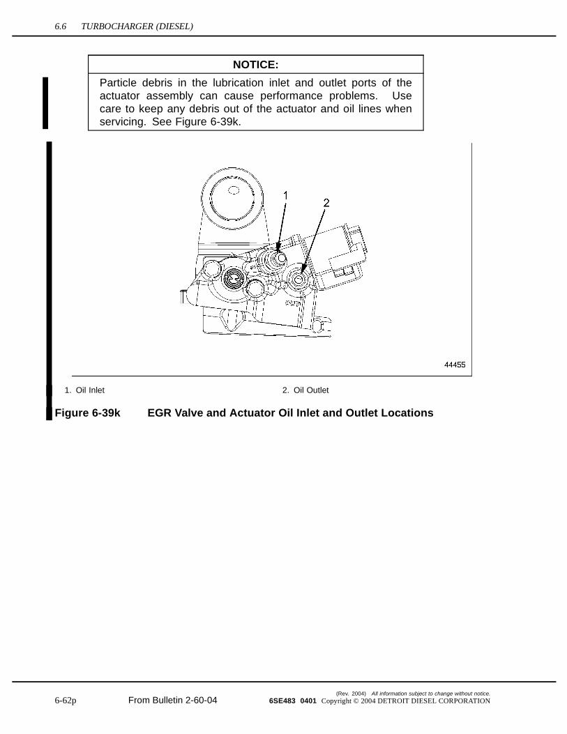
Particle debris in the lubrication inlet and outlet ports of theactuator assembly can cause performance problems. Usecare to keep any debris out of the actuator and oil lines whenservicing. See Figure 6-39k.
1. Oil Inlet 2. Oil Outlet
Figure 6-39k EGR Valve and Actuator Oil Inlet and Outlet Locations
(Rev. 2004) All information subject to change without notice.
6-62p From Bulletin 2-60-04 6SE483 0401 Copyright © 2004 DETROIT DIESEL CORPORATION

SERIES 60 SERVICE MANUAL
12. Install oil inlet and outlet lines on actuator assembly and torque to 24-28 N·m (18-21lb·ft). See Figure 6-39l.
1. EGR Valve and Actuator Assembly 3. Oil Outlet Line and Fitting
2. Oil Inlet Line and Fitting
Figure 6-39l EGR Valve Assembly with Oil Lines
All information subject to change without notice. (Rev. 2004)
6SE483 0401 Copyright © 2004 DETROIT DIESEL CORPORATION From Bulletin 2-60-04 6-62q

6.6 TURBOCHARGER (DIESEL)
This page intentionally left blank.
(Rev. 2004) All information subject to change without notice.
6-62r From Bulletin 2-60-04 6SE483 0401 Copyright © 2004 DETROIT DIESEL CORPORATION