6.3 Chemical reactors - Treccani
18
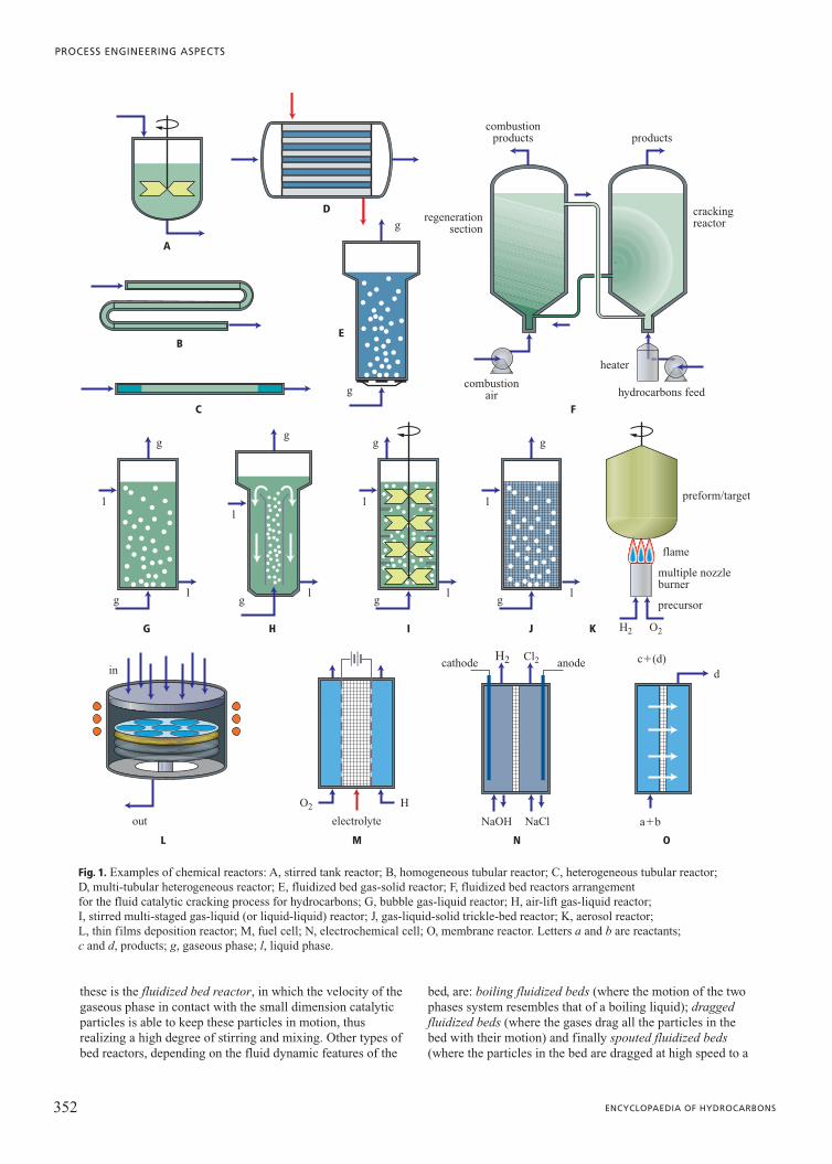
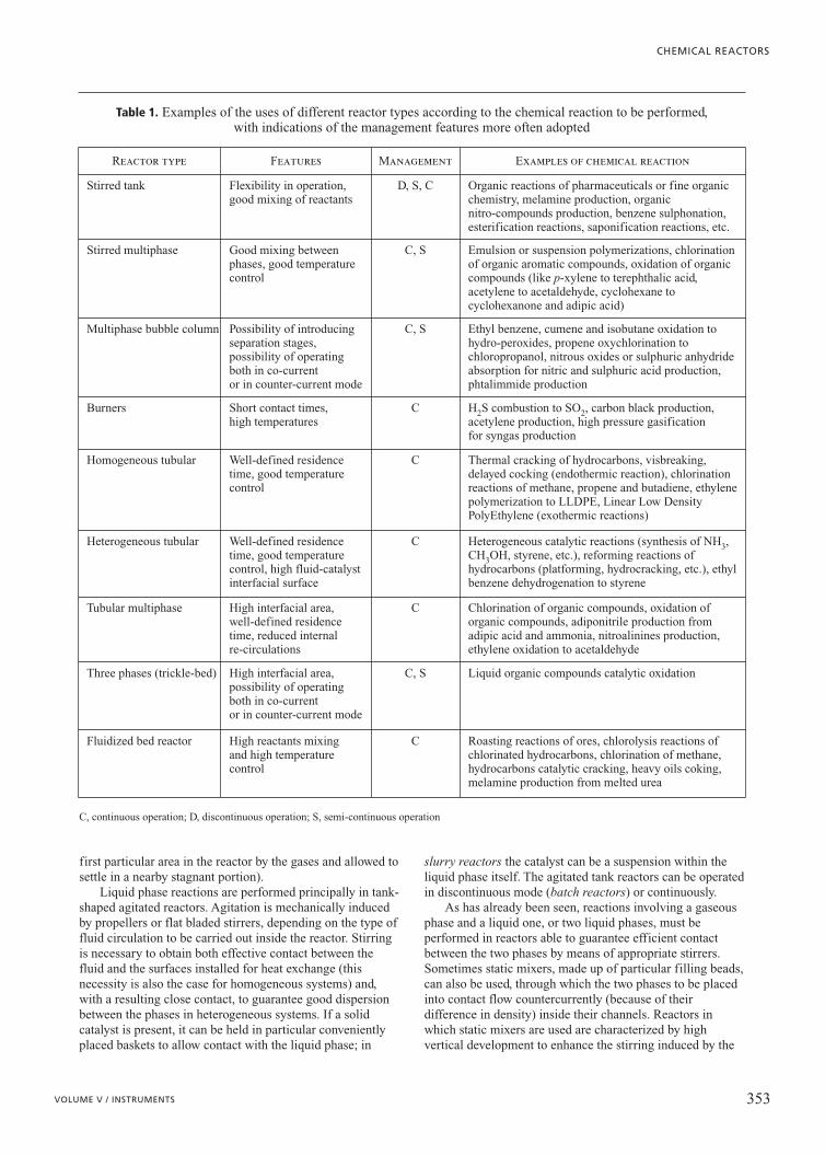
351 VOLUME V / INSTRUMENTS 6.3.1 General description and reactor types Chemical reactions pertaining to the chemical, petrochemical and oil industries are performed in special apparatus called reactors. There are distinct types of reactors intended to face extremely varied operating conditions, both in terms of the nature of the chemical species involved (reactants and products of the reaction) and of the physical conditions under which they operate. In general, a chemical reactor needs to be able to carry out at least three functions: provide the necessary residence time for the reactants to complete the chemical reaction; allow the heat exchange necessary; place the phases into intimate contact to facilitate the reaction. Thus, reactor types range from large dimension continuous reactors, like those adopted for catalytic cracking reactions, specifically for oil refineries, to devices of modest dimensions, like discontinuous stirred reactors in which fine and secondary chemistry reactions are performed. Moreover, there are reactors for sophisticated microelectronic applications and reactors of microscopic dimensions (microreactors), designed for biomedical installations or for in situ production of extremely toxic or dangerous compounds. Both converters and burners, catalytic or otherwise, adopted for energy production can also be listed among the reactors. To classify a reactor, the number of phases in the reactor itself, whether or not there are agitation systems and the mode of operation (continuous reactor, semi-continuous or discontinuous) need to be taken into consideration. It should also be noted that most chemical reactors are equipped with heat exchange apparatus in the form of external jackets or internal coils with a fluid flowing through them to act as a thermal vector to allow both heat supply or removal. Examples of different kinds of reactors are illustrated in Fig. 1, while the type of reactions operating inside them as well as the most usually adopted operation modes for the most common reactor types are reported in Table 1; the examples given show that the factors mainly influencing the choice of reactor type are: the number of phases involved, and thus whether or not it is necessary to provide particular agitation systems; obtaining and maintaining the optimal temperature and pressure for the reaction; and the scale of production which often determines continuous or discontinuous operation mode. As far as phases are concerned, the most simple reactors are homogeneous reactors, where a single gaseous or liquid phase is usually stirred to avoid the presence of stagnant zones. The reaction can be operated in discontinuous mode, by loading the reactants mixture into the reactor and waiting until the process is completed, or in continuous mode, by making a stream containing the reactants flow into the reactor and extracting another stream containing the reaction products. Typical examples of homogeneous reactors are those for thermal cracking and for polymerization in solution. Heterogeneous reactors are more complex, in which reactants, products and a possible catalyst can be present in different phases. One example is the fluid-solid reactor (gas-solid or liquid-solid), where heterogeneous catalytic reactions are performed. Another classic example is the tubular reactor which allows accurate temperature control because of its very extensive external surface available for heat exchange; in fact, it is designed as a tube bundle configuration very often, where a large number of reactors are connected in parallel, through each of which passes a fraction of the flow rate. Another example is the aerosol reactor, adopted by the industry of new materials, where solid particles are synthesized from reactants in gaseous phase. Gas-liquid or liquid-liquid reactors are even more complex, in which the main reactants are distributed between the two phases, immiscible with each other, but between which intimate contact has to be realized to make the reaction progress more easily. Multiphase reactors, like the gas-liquid-solid reactors, also exist; the trickle-bed reactor, used to perform hydrogenation reactions or catalytic oxidation reactions for liquid reactants, is a classic example. Reactions involving gaseous reactants are usually performed in tubular reactors, generally operating in turbulent regime; if a solid catalyst is involved, it is usually arranged as a bed of particles, generally in a spherical or cylindrical shape. If the mechanical features of the catalyst are appropriate and if efficient heat exchange is necessary to control the reaction temperature accurately, mobile bed reactors can be also used; the most important example of 6.3 Chemical reactors
Transcript of 6.3 Chemical reactors - Treccani
351VOLUME V / INSTRUMENTS
6.3.1 General description and reactor types
Chemical reactions pertaining to the chemical,petrochemical and oil industries are performed in specialapparatus called reactors. There are distinct types of reactorsintended to face extremely varied operating conditions, bothin terms of the nature of the chemical species involved(reactants and products of the reaction) and of the physicalconditions under which they operate.
In general, a chemical reactor needs to be able to carryout at least three functions: provide the necessary residencetime for the reactants to complete the chemical reaction;allow the heat exchange necessary; place the phases intointimate contact to facilitate the reaction.
Thus, reactor types range from large dimensioncontinuous reactors, like those adopted for catalytic crackingreactions, specifically for oil refineries, to devices of modestdimensions, like discontinuous stirred reactors in which fineand secondary chemistry reactions are performed. Moreover,there are reactors for sophisticated microelectronicapplications and reactors of microscopic dimensions(microreactors), designed for biomedical installations or forin situ production of extremely toxic or dangerouscompounds. Both converters and burners, catalytic orotherwise, adopted for energy production can also be listedamong the reactors.
To classify a reactor, the number of phases in the reactoritself, whether or not there are agitation systems and themode of operation (continuous reactor, semi-continuous ordiscontinuous) need to be taken into consideration. It shouldalso be noted that most chemical reactors are equipped withheat exchange apparatus in the form of external jackets orinternal coils with a fluid flowing through them to act as athermal vector to allow both heat supply or removal.
Examples of different kinds of reactors are illustrated inFig. 1, while the type of reactions operating inside them aswell as the most usually adopted operation modes for themost common reactor types are reported in Table 1; theexamples given show that the factors mainly influencing thechoice of reactor type are: the number of phases involved,and thus whether or not it is necessary to provide particularagitation systems; obtaining and maintaining the optimal
temperature and pressure for the reaction; and the scale ofproduction which often determines continuous ordiscontinuous operation mode.
As far as phases are concerned, the most simple reactorsare homogeneous reactors, where a single gaseous or liquidphase is usually stirred to avoid the presence of stagnantzones. The reaction can be operated in discontinuous mode,by loading the reactants mixture into the reactor and waitinguntil the process is completed, or in continuous mode, bymaking a stream containing the reactants flow into thereactor and extracting another stream containing the reactionproducts. Typical examples of homogeneous reactors arethose for thermal cracking and for polymerization insolution.
Heterogeneous reactors are more complex, in whichreactants, products and a possible catalyst can be present indifferent phases. One example is the fluid-solid reactor(gas-solid or liquid-solid), where heterogeneous catalyticreactions are performed. Another classic example is thetubular reactor which allows accurate temperature controlbecause of its very extensive external surface available forheat exchange; in fact, it is designed as a tube bundleconfiguration very often, where a large number of reactorsare connected in parallel, through each of which passes afraction of the flow rate. Another example is the aerosolreactor, adopted by the industry of new materials, wheresolid particles are synthesized from reactants in gaseousphase. Gas-liquid or liquid-liquid reactors are even morecomplex, in which the main reactants are distributed betweenthe two phases, immiscible with each other, but betweenwhich intimate contact has to be realized to make thereaction progress more easily. Multiphase reactors, like thegas-liquid-solid reactors, also exist; the trickle-bed reactor,used to perform hydrogenation reactions or catalyticoxidation reactions for liquid reactants, is a classic example.
Reactions involving gaseous reactants are usuallyperformed in tubular reactors, generally operating inturbulent regime; if a solid catalyst is involved, it is usuallyarranged as a bed of particles, generally in a spherical orcylindrical shape. If the mechanical features of the catalystare appropriate and if efficient heat exchange is necessary tocontrol the reaction temperature accurately, mobile bedreactors can be also used; the most important example of
6.3
Chemical reactors
these is the fluidized bed reactor, in which the velocity of thegaseous phase in contact with the small dimension catalyticparticles is able to keep these particles in motion, thusrealizing a high degree of stirring and mixing. Other types ofbed reactors, depending on the fluid dynamic features of the
bed, are: boiling fluidized beds (where the motion of the twophases system resembles that of a boiling liquid); draggedfluidized beds (where the gases drag all the particles in thebed with their motion) and finally spouted fluidized beds(where the particles in the bed are dragged at high speed to a
PROCESS ENGINEERING ASPECTS
352 ENCYCLOPAEDIA OF HYDROCARBONS
A
B
C
D
E
F
G I J K
L M N O
H
combustionproducts
g
g
g
g
ll
ll l l
g
g
l
g
H2
H
H2 Cl2
O2
O2
NaClNaOH
g
l
g
g
combustionair
electrolyte
cathode anode c�(d)d
a�bout
in
crackingreactorregeneration
section
heater
precursor
multiple nozzleburner
flame
preform/target
hydrocarbons feed
products
Fig. 1. Examples of chemical reactors: A, stirred tank reactor; B, homogeneous tubular reactor; C, heterogeneous tubular reactor; D, multi-tubular heterogeneous reactor; E, fluidized bed gas-solid reactor; F, fluidized bed reactors arrangement for the fluid catalytic cracking process for hydrocarbons; G, bubble gas-liquid reactor; H, air-lift gas-liquid reactor; I, stirred multi-staged gas-liquid (or liquid-liquid) reactor; J, gas-liquid-solid trickle-bed reactor; K, aerosol reactor; L, thin films deposition reactor; M, fuel cell; N, electrochemical cell; O, membrane reactor. Letters a and b are reactants; c and d, products; g, gaseous phase; l, liquid phase.
first particular area in the reactor by the gases and allowed tosettle in a nearby stagnant portion).
Liquid phase reactions are performed principally in tank-shaped agitated reactors. Agitation is mechanically inducedby propellers or flat bladed stirrers, depending on the type offluid circulation to be carried out inside the reactor. Stirringis necessary to obtain both effective contact between thefluid and the surfaces installed for heat exchange (thisnecessity is also the case for homogeneous systems) and,with a resulting close contact, to guarantee good dispersionbetween the phases in heterogeneous systems. If a solidcatalyst is present, it can be held in particular convenientlyplaced baskets to allow contact with the liquid phase; in
slurry reactors the catalyst can be a suspension within theliquid phase itself. The agitated tank reactors can be operatedin discontinuous mode (batch reactors) or continuously.
As has already been seen, reactions involving a gaseousphase and a liquid one, or two liquid phases, must beperformed in reactors able to guarantee efficient contactbetween the two phases by means of appropriate stirrers.Sometimes static mixers, made up of particular filling beads,can also be used, through which the two phases to be placedinto contact flow countercurrently (because of theirdifference in density) inside their channels. Reactors inwhich static mixers are used are characterized by highvertical development to enhance the stirring induced by the
CHEMICAL REACTORS
353VOLUME V / INSTRUMENTS
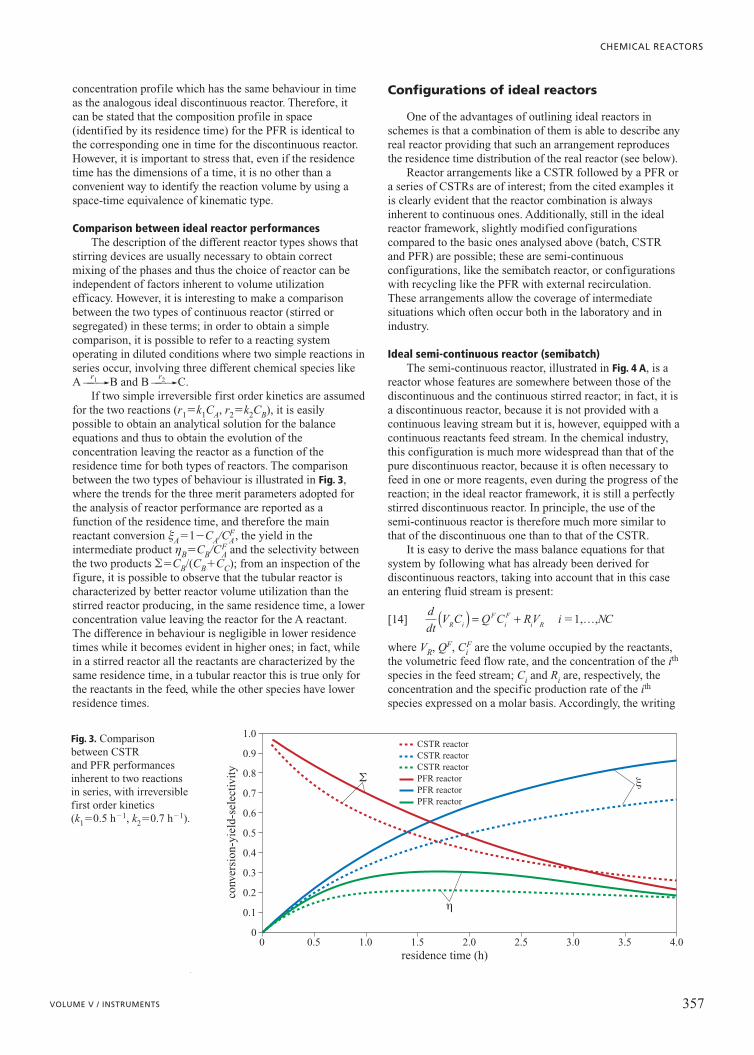
Table 1. Examples of the uses of different reactor types according to the chemical reaction to be performed,with indications of the management features more often adopted
Reactor type Features Management Examples of chemical reaction
Stirred tank Flexibility in operation,good mixing of reactants
D, S, C Organic reactions of pharmaceuticals or fine organicchemistry, melamine production, organicnitro-compounds production, benzene sulphonation,esterification reactions, saponification reactions, etc.
Stirred multiphase Good mixing betweenphases, good temperaturecontrol
C, S Emulsion or suspension polymerizations, chlorinationof organic aromatic compounds, oxidation of organiccompounds (like p-xylene to terephthalic acid,acetylene to acetaldehyde, cyclohexane tocyclohexanone and adipic acid)
Multiphase bubble column Possibility of introducingseparation stages,possibility of operatingboth in co-currentor in counter-current mode
C, S Ethyl benzene, cumene and isobutane oxidation tohydro-peroxides, propene oxychlorination tochloropropanol, nitrous oxides or sulphuric anhydrideabsorption for nitric and sulphuric acid production,phtalimmide production
Burners Short contact times,high temperatures
C H2S combustion to SO2, carbon black production,acetylene production, high pressure gasificationfor syngas production
Homogeneous tubular Well-defined residencetime, good temperaturecontrol
C Thermal cracking of hydrocarbons, visbreaking,delayed cocking (endothermic reaction), chlorinationreactions of methane, propene and butadiene, ethylenepolymerization to LLDPE, Linear Low DensityPolyEthylene (exothermic reactions)
Heterogeneous tubular Well-defined residencetime, good temperaturecontrol, high fluid-catalystinterfacial surface
C Heterogeneous catalytic reactions (synthesis of NH3,CH3OH, styrene, etc.), reforming reactions ofhydrocarbons (platforming, hydrocracking, etc.), ethylbenzene dehydrogenation to styrene
Tubular multiphase High interfacial area,well-defined residencetime, reduced internalre-circulations
C Chlorination of organic compounds, oxidation oforganic compounds, adiponitrile production fromadipic acid and ammonia, nitroalinines production,ethylene oxidation to acetaldehyde
Three phases (trickle-bed) High interfacial area,possibility of operatingboth in co-currentor in counter-current mode
C, S Liquid organic compounds catalytic oxidation
Fluidized bed reactor High reactants mixingand high temperaturecontrol
C Roasting reactions of ores, chlorolysis reactions ofchlorinated hydrocarbons, chlorination of methane,hydrocarbons catalytic cracking, heavy oils coking,melamine production from melted urea
C, continuous operation; D, discontinuous operation; S, semi-continuous operation

density difference between the two phases: the lower densityphase is fed from the bottom and collected at the top, whilethe other follows the opposite pathway. In gas-liquid reactorsthis configuration is called bubble column; differentconfigurations exist, intended to increase stirring and thuscontact between the phases, without resorting to mechanicalstirring devices. The most important example is the air-liftreactor, where the density difference between two connectedreactor portions is exploited to start a vortical naturalconvection motion.
In conclusion, it is also important to mention someatypical reactors, adopted for special applications. First ofall, there is the catalytic converter, a typical heterogeneouscatalytic reactor in which the exhaust gases from vehicles areput into contact with a catalyst whose active element is anoble metal, usually platinum, supported on a ceramicmatrix, generally a honeycomb monolithic structure. Insidethis reactor, carbon monoxide oxidizes to carbon dioxide andnitrogen oxides reduce to elementary nitrogen. The oxidantused in the first reaction is the oxygen still present in theexhaust gases, while the fuels for the reduction reaction arethe uncombusted hydrocarbons traces. The choice to adoptmonolithic structures allows the reduction of pressure dropsand the performance of efficient thermal exchanges. Otherimportant heterogeneous reactors are biological reactors,where the enzymes catalyzing the fermentation process aresupported on appropriate solid matrices. In this field, themost innovative applications are those made in bioreactorswhere selected cell colonies are allowed to proliferate withina biocompatible polymeric matrix. Electrochemical reactorsare characterized by having two electrodes, each at adifferent potential, between which an electric currenttransported by the ions contained in the electrolytic solutionflows, where they are both immersed. In this way, it ispossible to perform important industrial processes based onredox reactions, like chloro-alkali processes, which useelectric rather than thermal energy. Electrochemical reactorscan be likened to fuel cells with polymeric membrane, wherea combustion reaction takes place involving hydrogen (ormethanol) and oxygen by feeding the two gases on the twoelectrodes, separated by a ion exchange membrane, to makeelectric current generation possible. Both the two reactorsabove can also be classified as membrane reactors, where asemi-permeable membrane allows the separation of one ofthe reaction products directly from the reaction environmentthus contributing to an improvement in the selectivity of theprocesses under consideration. Currently, the extensiveapplication of these reactors is limited by the availability ofefficient membranes. Last but not least, reactors used inmicroelectronics, where chemical vapour depositionprocesses are performed, are of particular importance; thesereactors, operating in discontinuous conditions and at hightemperatures, allow the realization of extremely controlledprocess conditions so as to obtain highly contained tolerancelevels both of the thickness and of the crystallinemorphology of the deposited semiconductor.
6.3.2 Reactor design and simulation
In a chemical plant, the potential and the yield with respectto the reactants used depend on the size of the reactorsinvolved and on the mode in which they are operated.
Moreover, in many cases, the reactor cost accounts for asubstantial amount of the overall plant cost. Thus, correctreactor design is a fundamental requirement to realizeeconomically convenient plants.
Reactor design, once largely carried out with asemi-empirical approach, is today realized by means ofappropriate mathematical models, based on mass, energyand momentum conservation equations, intended to simulatereactor behaviour. The analytical formulations that make thedescription of the main reactor performances and featurespossible must thus take into consideration not only thekinetics features of the chemical reactions but also all thefluid dynamics aspects which influence the transport anddistribution of the reactants inside the reactor itself. Reactorworking conditions, when chemical and transportphenomena are both important, are called macrokinetics.
Such a description is generally very complex; thus, thereactors are often analysed first in ideal conditions where thefluid dynamic aspects are described in simple terms andwhere their behaviour is only dependent on chemicalreactions; these are called microkinetic conditions. From thispoint of view, the reactors can be represented by two limitingschemes (ideal reactors): one of a perfectly mixed systemand the other of a perfectly segregated system. In the firstcase, composition gradients are absent inside the reactor andthus the composition is uniform in the whole reactor volume;in the second case, the concentration of the reactants evolvesin the reactor volume and consequently the presence of theconcentration gradient represents its characterizing feature.It is then evident that the first limiting schematization issuitable for representing the stirred reactors while the secondone is appropriate for the tubular ones. Because real reactorbehaviour is at some point between those of the two limitingschematizations described above, it is clear why their studyis a good starting point before making more complexdescriptions later.
Once the ideal reactors have been studied, it is possibleto move forward to the examination of real ones by removingthe simplifications introduced, as far as giving a panoramaof the increasingly rigorous design methods, going throughan analysis of the residence time distribution function of thefluid within the reactor to the direct simulation of the flowfield through Navier-Stokes equations.
Models for isothermal ideal reactors
As has already been mentioned, the study of reactors isusually initially performed by means of two ideal models,where it is assumed that the fluid dynamics conditions donot influence the behaviour of the reacting system. Thatmeans considering a perfectly mixed volume, for the stirredreactors, and a perfectly segregated volume, for the tubularreactors. The continuous stirred reactors (CSTR, ContinuousStirred Tank Reactor) or the discontinuous ones (batchreactors) belong to the first class, while reactors with piston-like flux (PFR, Plug Flow Reactor) belong to the second one.
In the subsequent developments the following compactwriting for the chemical reactions will be adopted:
[1]
where Ai and nij are the ith chemical species and itsstoichiometric coefficient in the jth reaction, respectively.
ν ij ii
NC
A ==∑ 0
1
j NR�1,…,
PROCESS ENGINEERING ASPECTS
354 ENCYCLOPAEDIA OF HYDROCARBONS
Usually, the coefficients for the reaction products areassumed positive and the reactants negative. Accordingly, ifrj indicates the rate of the jth reaction, the specific productionterm for the ith chemical species is expressed as follows:
[2]
where Ri is specific production rate of the ith reactingspecies.
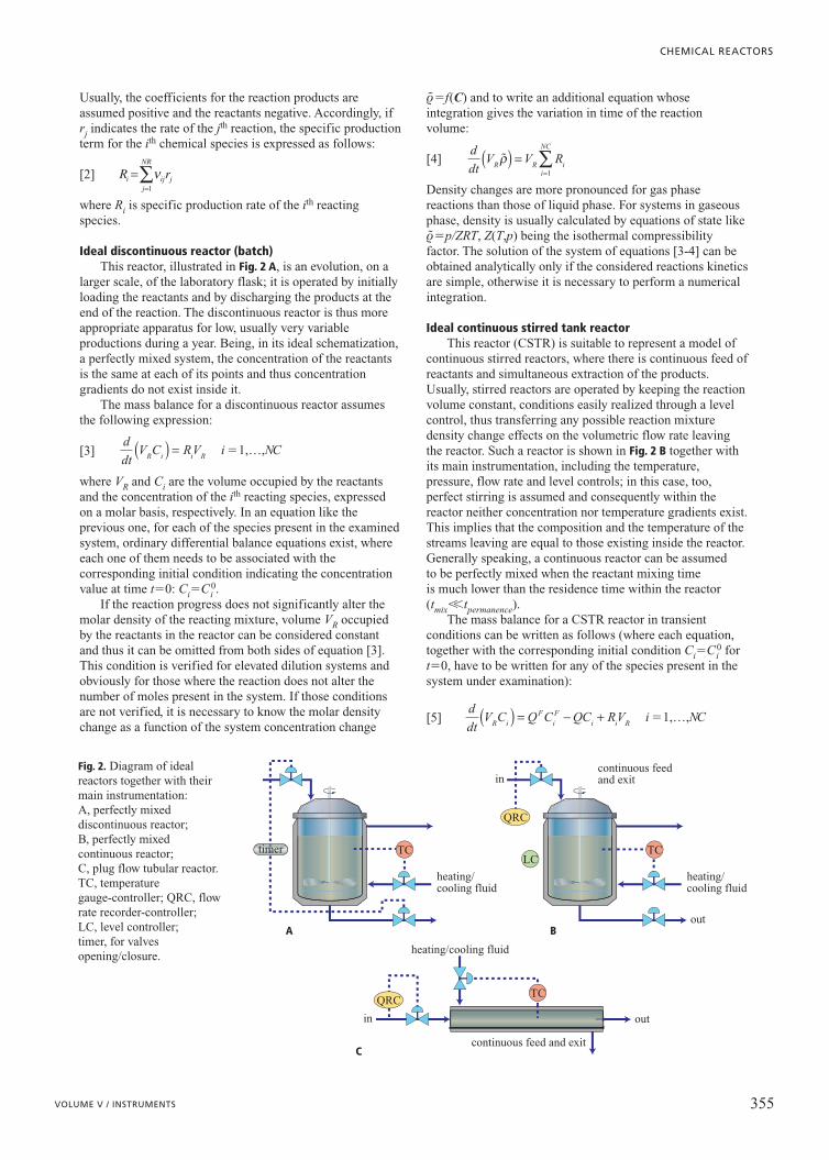
Ideal discontinuous reactor (batch)This reactor, illustrated in Fig. 2 A, is an evolution, on a
larger scale, of the laboratory flask; it is operated by initiallyloading the reactants and by discharging the products at theend of the reaction. The discontinuous reactor is thus moreappropriate apparatus for low, usually very variableproductions during a year. Being, in its ideal schematization,a perfectly mixed system, the concentration of the reactantsis the same at each of its points and thus concentrationgradients do not exist inside it.
The mass balance for a discontinuous reactor assumesthe following expression:
[3]
where VR and Ci are the volume occupied by the reactantsand the concentration of the ith reacting species, expressedon a molar basis, respectively. In an equation like theprevious one, for each of the species present in the examinedsystem, ordinary differential balance equations exist, whereeach one of them needs to be associated with thecorresponding initial condition indicating the concentrationvalue at time t�0: Ci�Ci
0.If the reaction progress does not significantly alter the
molar density of the reacting mixture, volume VR occupiedby the reactants in the reactor can be considered constantand thus it can be omitted from both sides of equation [3].This condition is verified for elevated dilution systems andobviously for those where the reaction does not alter thenumber of moles present in the system. If those conditionsare not verified, it is necessary to know the molar densitychange as a function of the system concentration change
r~ �f(C) and to write an additional equation whoseintegration gives the variation in time of the reactionvolume:
[4]
Density changes are more pronounced for gas phasereactions than those of liquid phase. For systems in gaseousphase, density is usually calculated by equations of state liker~ �p/ZRT, Z(T,p) being the isothermal compressibilityfactor. The solution of the system of equations [3-4] can beobtained analytically only if the considered reactions kineticsare simple, otherwise it is necessary to perform a numericalintegration.
Ideal continuous stirred tank reactorThis reactor (CSTR) is suitable to represent a model of
continuous stirred reactors, where there is continuous feed ofreactants and simultaneous extraction of the products.Usually, stirred reactors are operated by keeping the reactionvolume constant, conditions easily realized through a levelcontrol, thus transferring any possible reaction mixturedensity change effects on the volumetric flow rate leavingthe reactor. Such a reactor is shown in Fig. 2 B together withits main instrumentation, including the temperature,pressure, flow rate and level controls; in this case, too,perfect stirring is assumed and consequently within thereactor neither concentration nor temperature gradients exist.This implies that the composition and the temperature of thestreams leaving are equal to those existing inside the reactor.Generally speaking, a continuous reactor can be assumed to be perfectly mixed when the reactant mixing time is much lower than the residence time within the reactor(tmix��tpermanence).
The mass balance for a CSTR reactor in transientconditions can be written as follows (where each equation,together with the corresponding initial condition Ci�Ci
0 fort�0, have to be written for any of the species present in thesystem under examination):
[5]ddt
V C Q C QC RVR iF
iF
i i R( ) = − + i NC�1,…,
ddt
V V RR R ii
NC
�ρ( ) ==∑
1
ddt
V C RVR i i R( ) = i NC�1,…,
R ri ij jj
NR
==∑ν
1
CHEMICAL REACTORS
355VOLUME V / INSTRUMENTS
A B
C
timer
heating/cooling fluid
TC
heating/cooling fluid
heating/cooling fluid
control boundary surfacesection�WR
continuous feed and exit
continuous feed and exit
Fi(V) Fi(V�dV)
V V�dV
mol/t
TC
TC
in
in
out
out
LC
QRC
QRC
Fig. 2. Diagram of idealreactors together with theirmain instrumentation: A, perfectly mixeddiscontinuous reactor;B, perfectly mixedcontinuous reactor; C, plug flow tubular reactor.TC, temperaturegauge-controller; QRC, flowrate recorder-controller; LC, level controller; timer, for valvesopening/closure.
where Q, VR, Ci and Ri are the volumetric flow rate, thevolume occupied by the reactants, the concentration and thespecific production rate for the ith reacting species expressedon a molar basis, respectively; the F superscript identifiesthe properties inherent to the feed stream. Usually, the studyof these reactors is performed in steady state conditions, andthus the balance equations reduce to NC algebraic equations,generally not of linear type.
In all the continuous reactors, and thus also for theCSTR, the residence time (or contact time) is defined as theratio between the reaction volume and the feed volumetricflow rate:
[6]
tR represents the average residence time of the reactantswithin the reactor.
It is important to note that the volumetric flow rate forthe leaving stream can be different from that of the feed if, asa result of the effect of the chemical reactions, a change inthe number of moles, and consequently of the fluid molardensity, occurs. If this last property can be consideredconstant (r~ F�r~ ), the volumetric flow rate is also constant.Whenever it is not verified, in analogy with what happens inthe discontinuous reactor, it is necessary to have an equationexpressing the molar density change as a function of thesystem composition (r~ �f(C)) and to write an additionaloverall mass balance equation expressing the leaving flowrate change compared to the one entering the reactor:
[7]
where with F�Q/QF the ratio between the leaving and theentering volumetric flow rates is indicated. It is important tonote that if the mass balance equation were written on amass rather than a molar basis, in steady state conditions,equation [7] would be useless because the entrance massflow rate value is always equal to the one leaving.
To complete the examination and to justify the CSTRanalysis only in steady state conditions it is useful toexamine, at least once, their transient behaviour.Accordingly, it is useful to take a CSTR which initiallycontains the A reactant at concentration C0
A into examination,in which the irreversible reaction A��B, which follows firstorder kinetics (r�kCA) occurs and where only the A reactantis fed to the reactor. Under these conditions, theconservation of the volumetric flow rates is respectedbecause no variation in the number of moles takes place, andthus the mass balance equation for the A species can bewritten as follows:
[8]
whose analytical integration gives
[9]
where CA��CF
A /(1�ktR) is the asymptotic concentrationvalue, which represents the solution under steady stateconditions. It can be demonstrated that, under the consideredhypotheses, the time necessary to reach the steady statesolution is always the same, independent of the initialconcentration value. Moreover, this time is equal to about
three times the mean residence time of the reactants withinthe reactor.
Ideal piston flow continuous reactorThe ideal continuous reactor with piston-like flow (PFR)
is a model for the continuous tubular reactor; this reactor isshown in Fig. 2 C together with its main instrumentation. It isa perfectly segregated reactor model because compositiongradients develop inside it, from its entrance to its exit. Thismeans that in each reactor section a concentration change isobserved compared both to the previous section and the onefollowing. Thus, in the typical schematization of idealreactors, the fluid composition is homogeneous in eachsection of the reactor, while it varies continuously along itsmain developing axial coordinate.
To write balance equations for a PFR it is then necessaryto examine an infinitesimal volume of the reactor equal tothe area W of its section, multiplied by the infinitesimallength dz, which is dV�Wdz. The mass balance can bewritten as follows:
[10]
Each NC equation is referred to one component presentin the system under examination and it needs both aboundary condition, expressing the inlet conditions (Ci�Ci
F
for V�0), and an initial condition, expressing thecomposition profile along the whole reactor Ci(V)�Ci
0(V)for t�0. By introducing the ratio between the local flow ratevalue and the feed one (F�Q/QF), and the residence time(t�V/QF), the mass balance equation can be rewritten in thefollowing form:
[11]
The study of PFRs is also usually performed in steadystate conditions (�Ci/�t�0); in these conditions the partialdifferential equations system [11] reduces to the followingordinary differential equations system:
[12]
As for the CSTR, if the reaction does not alter thenumber of moles present in the fluid significantly and as aconsequence its molar density can be assumed constant(r~ F�r~ (t)�const), the volumetric flow rate is also constantand thus F�1. Whenever this condition is not verified, it isnecessary to have an equation expressing the molar densitychange as a function of the system composition (r~ �f(C ))and to write an additional equation giving the leaving flowrate change compared to that of the inlet:
[13]
It is important to note that if the mass balance were writtenon a mass rather than a molar basis, in steady stateconditions, this equation would also be useless, because themass flow rate values are always constant along the reactor.
It is important to note that in the case of constant density,equation [12] has exactly the same form as equation [3]derived for discontinuous reactors. This means that, byconsidering the same reaction and boundary conditions(and/or initial ones), the ideal PFR has an internal
∂∂τΦ �r( )
==∑ Rii
NC
1
d Cdt Ri
i
Φ⋅( )= ����i NC�1,…,
−( )
+ =∂∂τ
∂∂
ΦCR
Ct
ii
i i NC�1,…,
− + =∂∂
∂∂
( )
QCV
RCt
ii
i i NC�1,…,
C C C C eA A A Ak tR R= − −( )∞ ∞ − +0 1( ) /τ τ
C C kC CtA
FA R A R
A− − =τ τ ∂∂
� �r rFR i
i
NC
R− + ⋅ ==∑Φ τ
1
0
τ RRF
VQ
=
PROCESS ENGINEERING ASPECTS
356 ENCYCLOPAEDIA OF HYDROCARBONS
concentration profile which has the same behaviour in timeas the analogous ideal discontinuous reactor. Therefore, itcan be stated that the composition profile in space(identified by its residence time) for the PFR is identical tothe corresponding one in time for the discontinuous reactor.However, it is important to stress that, even if the residencetime has the dimensions of a time, it is no other than aconvenient way to identify the reaction volume by using aspace-time equivalence of kinematic type.
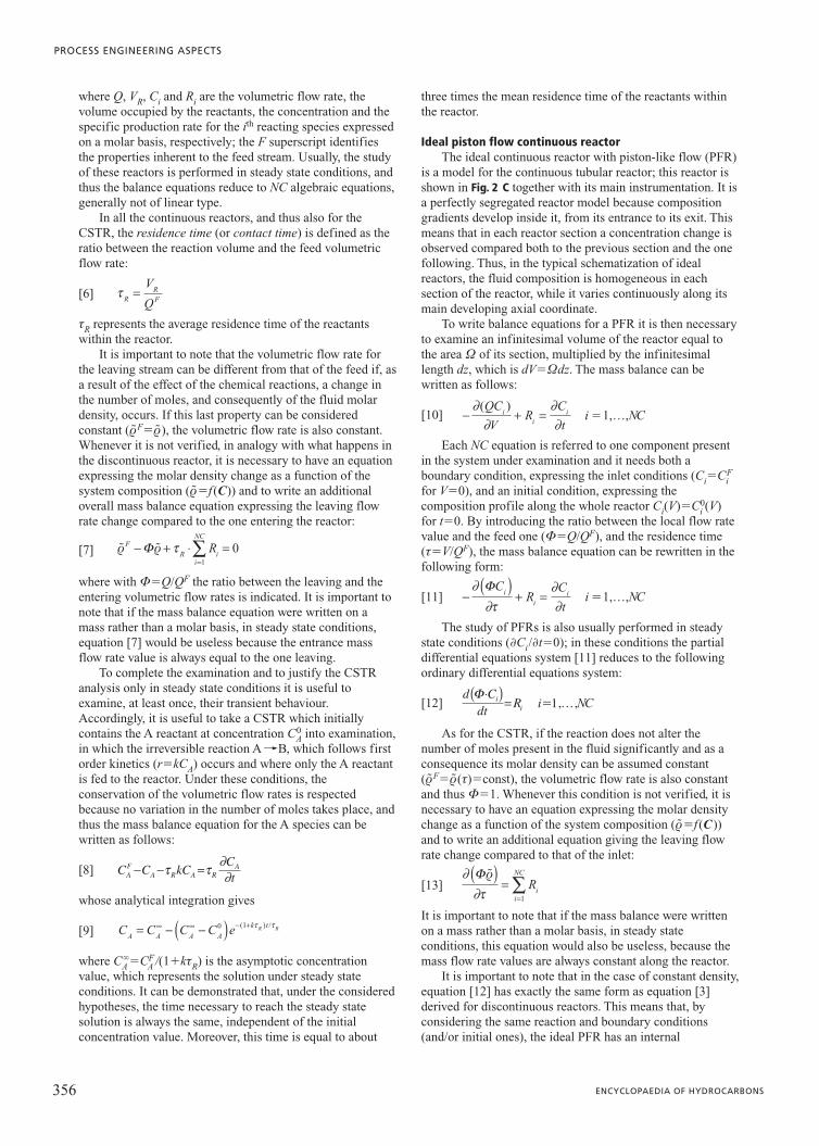
Comparison between ideal reactor performancesThe description of the different reactor types shows that
stirring devices are usually necessary to obtain correctmixing of the phases and thus the choice of reactor can beindependent of factors inherent to volume utilizationefficacy. However, it is interesting to make a comparisonbetween the two types of continuous reactor (stirred orsegregated) in these terms; in order to obtain a simplecomparison, it is possible to refer to a reacting systemoperating in diluted conditions where two simple reactions inseries occur, involving three different chemical species likeA�
r1���B and B�r2���C.
If two simple irreversible first order kinetics are assumedfor the two reactions (r1�k1CA, r2�k2CB), it is easilypossible to obtain an analytical solution for the balanceequations and thus to obtain the evolution of theconcentration leaving the reactor as a function of theresidence time for both types of reactors. The comparisonbetween the two types of behaviour is illustrated in Fig. 3,where the trends for the three merit parameters adopted forthe analysis of reactor performance are reported as afunction of the residence time, and therefore the mainreactant conversion xA�1�CA/CF
A, the yield in theintermediate product hB�CB/CF
A and the selectivity betweenthe two products ��CB/(CB�CC); from an inspection of thefigure, it is possible to observe that the tubular reactor ischaracterized by better reactor volume utilization than thestirred reactor producing, in the same residence time, a lowerconcentration value leaving the reactor for the A reactant.The difference in behaviour is negligible in lower residencetimes while it becomes evident in higher ones; in fact, whilein a stirred reactor all the reactants are characterized by thesame residence time, in a tubular reactor this is true only forthe reactants in the feed, while the other species have lowerresidence times.
Configurations of ideal reactors
One of the advantages of outlining ideal reactors inschemes is that a combination of them is able to describe anyreal reactor providing that such an arrangement reproducesthe residence time distribution of the real reactor (see below).
Reactor arrangements like a CSTR followed by a PFR ora series of CSTRs are of interest; from the cited examples itis clearly evident that the reactor combination is alwaysinherent to continuous ones. Additionally, still in the idealreactor framework, slightly modified configurationscompared to the basic ones analysed above (batch, CSTRand PFR) are possible; these are semi-continuousconfigurations, like the semibatch reactor, or configurationswith recycling like the PFR with external recirculation.These arrangements allow the coverage of intermediatesituations which often occur both in the laboratory and inindustry.
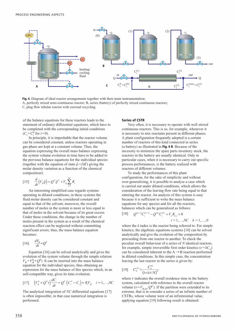
Ideal semi-continuous reactor (semibatch)The semi-continuous reactor, illustrated in Fig. 4 A, is a
reactor whose features are somewhere between those of thediscontinuous and the continuous stirred reactor; in fact, it isa discontinuous reactor, because it is not provided with acontinuous leaving stream but it is, however, equipped with acontinuous reactants feed stream. In the chemical industry,this configuration is much more widespread than that of thepure discontinuous reactor, because it is often necessary tofeed in one or more reagents, even during the progress of thereaction; in the ideal reactor framework, it is still a perfectlystirred discontinuous reactor. In principle, the use of thesemi-continuous reactor is therefore much more similar tothat of the discontinuous one than to that of the CSTR.
It is easy to derive the mass balance equations for thatsystem by following what has already been derived fordiscontinuous reactors, taking into account that in this casean entering fluid stream is present:
[14]
where VR, QF, CiF are the volume occupied by the reactants,
the volumetric feed flow rate, and the concentration of the ith
species in the feed stream; Ci and Ri are, respectively, theconcentration and the specific production rate of the ith
species expressed on a molar basis. Accordingly, the writing
ddt
V C Q C RVR iF
iF
i R( ) = + i NC�1,…,
CHEMICAL REACTORS
357VOLUME V / INSTRUMENTS
conv
ersi
on-y
ield
-sel
ectiv
ity
0
0.1
0.2
0.3
0.4
0.5
0.6
0.7
0.8
0.9
1.0
residence time (h)
CSTR reactorCSTR reactor CSTR reactor PFR reactor PFR reactor PFR reactor
x
h
S
0 0.5 1.0 1.5 2.0 2.5 3.0 3.5 4.0
Fig. 3. Comparison between CSTR and PFR performancesinherent to two reactions in series, with irreversible first order kinetics (k1�0.5 h�1, k2�0.7 h�1).
of the balance equations for these reactors leads to thestatement of ordinary differential equations, which have tobe completed with the corresponding initial conditions(Ci�Ci
0 for t�0).In principle, it is improbable that the reactor volume
can be considered constant, unless reactors operating ingas phase are kept at a constant volume. Thus, theequation expressing the overall mass balance expressingthe system volume evolution in time have to be added tothe previous balance equations for the individual species(together with the equation of state r~ �f(C) giving themolar density variation as a function of the chemicalcomposition):
[15]
An interesting simplified case regards systemsoperating in diluted conditions; in these systems thefluid molar density can be considered constant andequal to that of the solvent; moreover, the overallnumber of moles in the system is more or less equal tothat of moles in the solvent because of its great excess.Under these conditions, the change in the number ofmoles present in the system as a result of the chemicalreaction effect can be neglected without committingsignificant errors; thus, the mass balance equationbecomes:
[16]
Equation [16] can be solved analytically and gives theevolution of the system volume through the simple relationVR�V0
R�QFt. It can be inserted into the mass balanceequation for the individual species, thus obtaining anexpression for the mass balance of this species which, in anself-compatible way, gives its time evolution:
[17]
The analytical integration of NC differential equations [17]is often impossible; in that case numerical integration isperformed.
Series of CSTRVery often, it is necessary to operate with well stirred
continuous reactors. This is so, for example, whenever itis necessary to mix reactants present in different phases.A plant configuration frequently adopted is a certainnumber of reactors of this kind connected in series (a battery) as illustrated in Fig. 4 B. Because of thenecessity to minimize the spare parts inventory stock, thereactors in the battery are usually identical. Only inparticular cases, when it is necessary to carry out specificprocess performances, is the battery realized withreactors of different volumes.
To study the performances of this plantconfiguration, for the sake of simplicity and withoutover-generalizing, it is possible to analyse a case whichis carried out under diluted conditions, which allows theconsideration of the leaving flow rate being equal to thatentering the reactor. An analysis of this system is easybecause it is sufficient to write the mass balanceequations for any species and for all the reactors,balances which can be generalized as follows:
[18]
where the k index is the reactor being referred to. For simplekinetics, the algebraic equations systems [18] can be solvedanalytically and give the evolution of the composition byproceeding from one reactor to another. To check thepeculiar overall behaviour of a series of N identical reactors,for example, simple irreversible first order kinetics (r�kCA)can be considered inherent to the A��B reaction performedin diluted conditions. In this simple case, the concentrationleaving the last reactor in the series is given by:
[19]
where t indicates the overall residence time in the batterysystem, calculated with reference to the overall reactorvolume (t�VR,tot/Q
F). If the partition were extended to itsextreme, that is to consider a series of an infinite number ofCSTRs, whose volume were of an infinitesimal value,applying equation [19] following result is obtained:
C Ck NA
N AN
( )( )
/=
+( )0
1 τ
…i NC�1, , 1, ,k N� …Q C Q C V Rk
ik k
ik
k k i( ) ( ) ( ) ( )
,
− − − + =1 1 0
V Q tdCdt
Q C C RVRF i F
iF
i i R0 +( ) = −( ) + i NC�1,…,
dVdt QR F=
ddt
V Q V RRF F
R ii
NC
� �r r( ) = +=∑
1
PROCESS ENGINEERING ASPECTS
358 ENCYCLOPAEDIA OF HYDROCARBONS
A
B
C
timer
heating/coolingfluid
in
(0)(1) (2)
(3)
out
in outCi
(1)
CiF�Ci
(0) Ci(out)�Ci
(2)R
Q Q
Ci(2)
Ci(2)
LCTC
QRC
Fig. 4. Diagram of ideal reactor arrangements together with their main instrumentation: A, perfectly mixed semi-continuous reactor; B, series (battery) of perfectly mixed continuous reactors; C, plug flow tubular reactor with external recycling.
[20]
that is, a series of infinite CSTRs is equivalent to a PFR.In actual fact, in industrial practice, batteries with more
than 4 or 5 reactors are rarely used: indeed, even at thispartitioning level performances comparable with those oftubular reactors can be reached.
PFR with external recyclingTo realize a perfectly stirred reactor (a reactor which
at any point has the same chemical composition) is notan easy task. One way to realize a perfect CSTR, at leaston a laboratory scale, is to build a tubular reactor (PFR)with external recycling as shown in Fig. 4 C. Note thepresence of a mixing node (feed�recycle) and apartitioning node (where the flow rate leaving thereactor is split between the real exit stream and therecycling stream back to the feed). It is important tounderline that the partitioning node does not alter thecomposition of the fluid streams involved because it onlysplits the main stream into two secondary streams; themixing node instead, also alters the composition besidesthe flow rates. In fact, the stream leaving the node has aflow rate that is the sum of those of the entrance and acomposition that is the weighted compositions averageof the two feed streams whose weights are determined bythe respective flow rates.
To study the performances of these configurations, forsake of simplicity and without overgeneralizing, it ispossible to analyse the case where diluted conditions areexamined. The analysis of this system is simple because it issufficient to write the mass balance equations for all thespecies inherent to the tubular reactor and relative to the feednode:
[21]
[22]
For simple kinetics, like that of the irreversible first order(r�kCA), inherent to the A��B reaction, the system ofdifferential equations [21] can be solved analytically toprovide the composition evolution along the reactor. Byanalytically integrating the mass balance equation for the Areactant and combining it with the node balance [22], thecomposition value leaving the reactor can be directlyobtained from that of the entrance as a function of therecycling ration f�R/Q and of the residence time,calculated with respect to the inlet flow rate to the systemtR�VR/Q:
[23]
It is easy to demonstrate that by increasing the recyclingratio f the reactor performances decrease (that is, theleaving concentration CA
(2) increases). For values approachinginfinite (f���), equation [23] degenerates in the typicalCSTR expression: CA
(2)�CA(0)/(1�ktR). In practice, an infinite
recycling ratio is not necessary: in fact, values in between 50and 100 are sufficient to obtain perfectly stirred reactorperformances. Whenever more complex kinetics areexamined, the indicated values can submit to significant
changes and thus it is important to verify the soundness ofthe approximation directly from the case under examination.
Ideal non-isothermal reactor models
Rarely are chemical reactions free from thermal effects.Thus, in studies of chemical reactors it is also necessary tointroduce, in addition to the mass balance equations, that ofthe energy balance. This equation gives the systemtemperature evolution as a function of the reaction progressand of the amount of heat exchanged with the surroundingenvironment by means of fluids acting as thermal vectors;writing the energy balance will be developed here withreference to the ideal reactors previously examined; extendingthat equation to the more complex reactors is simple.
The energy balance for a chemical reactor contains thecontributions due to the energy content of the involvedchemical species (by taking into account both the breakingand the formation of chemical bonds during the reaction,both the feeding and the extraction of the reactants by meansof the entering and leaving streams), to the heat exchangedwith the surroundings and to viscous dissipation. Generally,the latter contribution is not such an important percentageexcept for cases where high viscosity systems are examined,typical, for example, of some polymerization reactors.
Discontinuous reactorThe internal energy U of the fluid contained inside the
reactor can vary over time uniquely due to the energyexchanged in the unit of time with the external surroundings,under the form of both heat Q
.and mechanical work W
.(the
latter component is usually negligible):
[24]
The heat power Q.
exchanged with the external surroundings,which is nil only in the case of adiabatic reactor operation,depends on the difference between the internal temperatureof the reactor T and that of the thermal vector fluid Te, on thereactor surface available for heat exchange SR and on theoverall energy transfer coefficient Ug, which accounts for allheat transfer resistance:
[25]
In practice, it is useful to directly identify the systemtemperature and the contributions due to the chemicalreactions involved; to obtain this result it is sufficient toexpress the internal energy as a function of the systemcomposition, U�VR�iCi(DUi
0�∫TT0cV,idT ), and to substitute
mass balance equation [3] in equation [24]:
[26]
where DUR, j indicates the molar internal energy change attemperature T associated with the jth chemical reaction.Moreover, to be compact, the sum of the products betweenthe concentration and the heat capacity for the ith chemicalspecies at a constant is usually indicated as rcV, mix.
Perfectly stirred continuous reactorThe approach shown for the discontinuous reactor can be
immediately extended to the perfectly stirred continuousreactor, being sure to introduce enthalpic contributions H
F
V C c dTdt
V r U S UR i V ii
NC
R j R jj
NR
R� �, ,
= =∑ ∑= −( )+
1 1
∆ gg eT T W−( )+ �
�Q S U T TR g e= −( )
dUdt Q W= +� �
C C eeA
Ak
k
R
R
( )( ) /( )
/( )2
0 1
11=
+ −
− +
− +
τ ϕ
τ ϕϕ ϕ
QC RC Q R CiF
i i+ = +( ) ( )( )2 1
dCd
R C Ci
Ri i R iτ
τ= = = ( ) ( )0 1 i NC�1,…,
lim lim/
exp(( )( )
( )
N AN
N
AN AC C
k NC
→∞ →∞=
+( )= −
00
1 τkkτ )
CHEMICAL REACTORS
359VOLUME V / INSTRUMENTS
and H into the balance terms for the entering and the leavingreactor streams, respectively:
[27]
In practice, in this case too, it is useful to directly identifythe system temperature and the contributions due to thechemical reactions involved. To obtain this result, it issufficient to express the molar enthalpy of the stream as afunction of the system composition,H ��iCi(DU i
0�∫T
T0cp,idT ), and to substitute the mass balance
equation [5] in equation [27]; in steady state conditions thisobtains:
[28]
where DH R, j0 indicates the standard molar energy change
associated with the jth chemical reaction. Moreover, to becompact, usually rcV, mix(T�TF ) indicates the sum of theproducts of the concentrations of the ith chemical specieswith the integral of its heat capacity at constant pressurebetween the temperatures of the entering and leavingstreams.
Continuous tubular reactorTo write the energy balance equation for a tubular
reactor it is necessary to refer to an infinitesimal volumeinstead of the entire reactor volume:
[29]
where aR indicates the heat exchange surface per unit reactorvolume (which, for a tubular reactor coincides with the ratiobetween the perimeter and the section of the tube). It is to benoted that there are no power dissipation terms due tomechanical devices because there are none in tubularreactors. To obtain the expression for the temperatureevolution, the previously described procedure can befollowed, which in steady state conditions leads to:
[30]
being rcp, mix��iCicp,i
Thermal effects: multiplicity of steady statesand runaway
In a chemical reactor, the absorbed, or generated, heatfrom chemical reactions is given or subtracted through a heatexchanger. In steady state conditions, the two heat fluxeshave to be equivalent to keep the reacting systemtemperature constant. This observation is at the basis of animportant phenomenon typical of continuous stirredreactors, which can be easily demonstrated by equations [28]and [5], where, for sake of simplicity, a unique reaction withirreversible first order kinetics is performed in dilutedconditions. By taking into account that the reaction kineticconstant generally assumes the Arrhenius form k�k0e�E/RT,where k0 and are the frequency factor and E the activationenergy of the reaction, respectively; the two contributions forthe heat power generated and dissipated are the following:
[31]
[32]
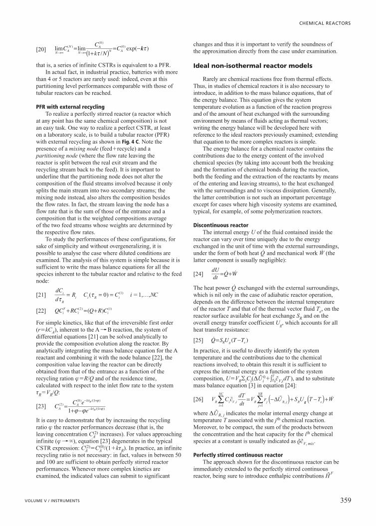
As shown in Fig. 5, the curve of the generated thermal poweras a function of temperature shows a typical S-shaped curve,while the curve of the dissipated one has almost linearbehaviour. It follows that the intersections between equations[31] and [32] represent the possible working conditions forthe reactor. Moreover, it can be observed that the number ofintersections varies as a function of the inclination of thestraight line representing the dissipated heat: either threeintersections or only one intersection is thus possible.Therefore, in the first case, the continuous stirred reactorpresents a multiplicity of steady states. The stability analysisof the working conditions creates an eigenvalues problem,whose analysis, however, goes beyond the aims of thisarticle. To sum up, such an analysis definitely states thatonly the cold point (a in Fig. 5) and the hot point (c in Fig. 5)are stable working points for the reactor, while theintermediate one (point b in Fig. 5) is unstable and thus anysmall disturbance induced in the reactor produces amigration towards one of the other two working conditions.
Another interesting effect, with dangerousconsequences, is fugitive (runaway) reactor behaviour. Thisis typical of exothermic reactions and is independent of thereactor type under consideration: if a disturbance in itsbehaviour prevents thermal control, then it causes either atemperature increase or a decrease in the heat dissipationcapacity (exponential behaviour of the generated heatcurve); the system is not able to react to the disturbance andthere is a loss of control in the working conditions, whichprovokes sharp temperature increases with the consequentformation of unwanted by-products or dangerous sharppressure increases. A simple criterion for this analysis was
� � �Q Q c T T S U T TexF
p mixF
R g e= − + −r , ( ) ( )
� ��
Q r H Vk e C H
k egen R R
E RTiF
RE= − =−
+
−
−∆∆
0
0 0
01
/ ( )
τ //RT RV
Q c dTdV
r H a U T Tp mix j R jj
NR
R g e� � �r
, ,= −( ) + −(
=∑ ∆ 0
1
))
∂∂
= −∂∂
+ −( ) ( ) ( )� � � �r rUt
Q HV
a U T TR g e
V r HR j R jj
NR�
,=
= −( )0
1
∆∑∑ + −( )+S U T T WR g e�
Q C c dTFiF
p iT
T
i
NC
F
�,∫∑
=
=1
dUdt
Q H Q H S U T T WF F FR g e= − + − +� � � � �r r ( )
PROCESS ENGINEERING ASPECTS
360 ENCYCLOPAEDIA OF HYDROCARBONS
Q
(c)
(a)
(b)
(d)
Qex
T
.
Qgen.
.
Fig. 5. Behaviour of generated and dissipated heat powers for a CSTR. Steady states multiplicity analysis: a, cold working point; b, unstable working point; c, hot working point; d, single intersection.
proposed by Nikolaj Nikolaevic Semënov, by means of thedefinition of a dimensionless number y, given by the ratiobetween the generated heat in the reaction volume at thefluid temperature and the heat dissipation velocity by pureNewtonian cooling, that is by convective heat transfertowards a constant temperature wall:
[33]
If the Semënov number is lower than the critical valueycr�e�1, the reactor behaves in a stable manner; otherwise,runaway conditions take place. The advantage inherent to theSemënov number is its simplicity. However, today moresophisticated criteria are available for risk estimation.
Real (non-ideal) reactor models
In practice, it is difficult to obtain perfect stirring orsegregation conditions and thus the real behaviour of chemicalreactors is substantially between the two limiting cases. Themixing effects in reactors are often divided between thecontributions of two distinct mechanisms: micromixing, whichdetermines the degree of contact between species at molecularlevel due to the local turbulent fluctuations of fluid velocity,and macromixing, which instead is the result of the differentpaths and by-pass fluxes or of the presence of stagnant zoneswithin the reactor. The two contributions are independent ofeach other and therefore a macromixing state does notcorrespond to an equivalent micromixing state, even thoughthere is an influence common to both.
An effective way to study such a situation is based on theresidence time distribution function F(t), which accounts forflux non uniformity and whose product with dt, F(t)dt,
expresses the fraction of fluid whose residence time isbetween t and t�dt; the F(t) function must be normalizedto obtain:
[34]
As a consequence, the mean residence time of the reactantswithin the reactor is given by:
[35]
Once the residence time distribution function is known,real reactor behaviour can be simulated by taking intoconsideration an ensemble of reactors, each one linked to aspecific residence time, to finally reproduce the F(t)function. In practice, the F(t) can be obtained by injecting atracer into the reactor under examination, whoseconcentration within the reactor can be determined at anymoment. For a perfectly stirred continuous reactor, after astep disturbance of the entrance conditions, the residencetime distribution function has an asymptotic exponentialtrend, F(t)CSTR
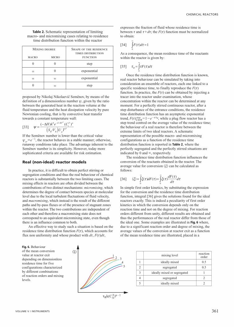
step �1�e�t/tR, while a plug flow reactor has astep trend centred on the average value of the residence time;the behaviour of a real reactor is therefore between theextreme limits of two ideal reactors. A schematicrepresentation of the possible macro- and micromixingconfigurations as a function of the residence timedistribution function is reported in Table 2, where theperfectly segregated and the perfectly stirred situations areindicated by 0 and �, respectively.
The residence time distribution function influences theconversion of the reactants obtained in the reactor. Theaverage value for conversion �x� can be calculated asfollows:
[36]
In simple first order kinetics, by substituting the expressionfor the conversion and the residence time distributionfunction, integral [36] gives the solutions found for the idealreactors exactly. This is indeed a peculiarity of first orderkinetics in which the conversion depends only on thereaction time and not on the degree of mixing. For reactionorders different from unity, different results are obtained andthus the performances of the real reactor differ from those ofthe ideal one. Some examples are illustrated in Fig. 6 where,due to a significant reaction order and degree of mixing, theaverage values of the conversion at reactor exit as a functionof the mean residence time are illustrated, placed in a
� �ξ ξ τ τ ξ τ ττ
τ= =∞ ∞
∫ ∫( ) ( ) ( ) ( )
0 0
dF dFd
d
τ τ τ τR F d=∞
∫ ( )0
F d( )τ τ0
1∞
∫ =
ψ =−
( )−( ) ( )/∆H k e C
S V U T
E RTiF n
R R gF
F0
�
CHEMICAL REACTORS
361VOLUME V / INSTRUMENTS
1
1 0.5ideally mixed
reactionordermixing level
2 0.5segregated
3 1ideally mixed or segregated
4 2segregated
5 2ideally mixed
2
�x�
34
5
tRk(CAF)n�1
Fig. 6. Behaviour of the mean conversion value at reactor exitdepending on dimensionlessresidence time for fiveconfigurations characterizedby different combinations of reaction orders and mixinglevels.
Table 2. Schematic representation of limitingmacro- and micromixing cases relating to residence
time distribution function within the reactor
Mixing degree
macro micro
Shape of the residencetimes distribution
function
0 0 step
� 0 exponential
� � exponential
0 � step
dimensionless form with respect to the pseudo-first orderrate constant. It can be demonstrated that to know the realperformances of these systems it is necessary to determinetheir fluid dynamics behaviour correctly by taking intoaccount both the fluid macro-circulation and the microscopicmixing phenomena due to system turbulence.
As will be examined in detail below, today this problemis faced by means of rigorous reactor simulations based oncomputational fluid dynamics. However, there are twoapproaches that facilitate a description of the behaviour of areal reactor, which are more simple than that mentionedabove. The first originates from the observation that a seriesof CSTR is able to adjust its performance to between that ofa single CSTR (perfectly stirred reactor) and that of a PFR(perfectly segregated reactor); as a consequence, it ispossible to model real reactor behaviour by considering itsvolume partitioned into an appropriate number of idealCSTRs, whose number is intended to reproduce theresidence time distribution function. The second approach,instead, derives real reactor behaviour from that of the PFR,by introducing dispersion effects perturbing perfectsegregation, due to the local diffusion of the reactants; suchcases are identified as axial dispersion models, whosebalance equations assume the following form:
[37]
where z, u and DL,i indicate the axial reactor coordinate, theaverage fluid velocity within the channel (usually called thesuperficial velocity) and its axial dispersion coefficient,respectively. The latter, which has the dimensions of adiffusion coefficient, accounts for the dispersion of theconcentration front merely due to diffusive aspects(concentration gradient) and to deviations of the velocityprofile from the idealized one, constant in the whole section.
The introduction of dispersion conditions introduces amodification in the boundary conditions of mass balanceequation [37] compared to those of equation [10]. In fact, theconditions inherent to the inlet and the exit sections of thereactor assume the following form:
[38a]
[38b]
While the latter simply indicates a fully developedconcentration profile at reactor exit, the first shows theexistence of discontinuity in concentration value of thereactants in correspondence with the inlet section, dueprecisely to the dispersion effects within the reactor. Theseboundary conditions are usually indicated as Dankwertsconditions, even though they were formulated for the firsttime by Irving Langmuir.
It is important to point out that both the approachesillustrated above (a series of CSTRs and an axial dispersionreactor) are able to reproduce the behaviour of any genericreactor. In fact, it is possible to shift from one type ofdescription to another by obtaining, for example, the numberof reactors in a series which reproduces the value of the axialdispersion coefficient and vice versa, through appropriatecorrelations. The choice between one or the otherschematization is usually based on its computationalcomplexity (in favour of the battery) or on affinity of themodel to reality (a dispersion model apparently betterapproximates the behaviour of a tubular reactor than a stirredreactor). To reproduce the real behaviour of a reactor morecomplex combinations of reactors are often also examined,like those illustrated in Fig. 7, for example.
Heterogeneous reactor models
Only single phase reactors have been examined up to thispoint. As has already been seen, in a real situation, it is veryfrequent for reactants to be distributed among more than onephase. Heterogeneous catalytic, gas-liquid and liquid-liquidreactors are classic examples of this as well as three phasegas-liquid-solid reactors.
In all the heterogeneous reactors the dispersion of onephase is carried out inside the other. For the correct reactordefinition it is therefore necessary to establish which phase iscontinuous and which is the dispersed phase. Inheterogeneous catalytic reactors, the catalyst particlesrepresent the dispersed phase while the fluid phase identifiesthe continuous one. In gas-liquid reactors two limitingconfigurations are possible: in the first, the most frequent, the
0=− ∂∂
D CzL ii
L,
u C C D Czi i
FL i
i( ) ,− =− ∂∂ 0
∂∂
=− ∂∂
+ ∂∂
+Ct
u Cz
D Cz
Ri iL i
ii,
2
2
PROCESS ENGINEERING ASPECTS
362 ENCYCLOPAEDIA OF HYDROCARBONS
A
D E
B C
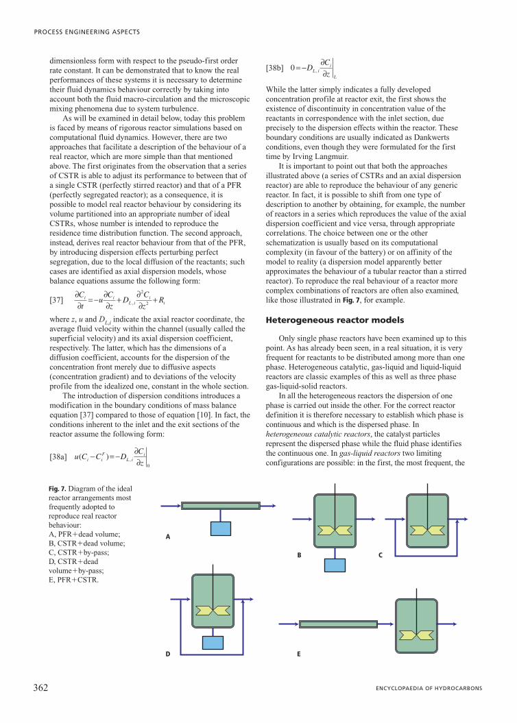
Fig. 7. Diagram of the idealreactor arrangements mostfrequently adopted toreproduce real reactorbehaviour:A, PFR�dead volume; B, CSTR�dead volume;C, CSTR�by-pass; D, CSTR�dead volume�by-pass; E, PFR�CSTR.

liquid phase is the continuous one while the gas bubbles arethe dispersed phase (bubble reactors, whether or not equippedwith external stirring); in the second case, less frequent, theliquid phase is dispersed in the gaseous phase (spray reactors,where liquid drops are sprayed within the gaseous phase).
In all the heterogeneous reactors the heat and masstransfer between phases plays an important role in definingtheir performances. In the following, the differenthomogeneous reactor models will be modified to representthe heterogeneous system.
Heterogeneous catalytic reactorsIn heterogeneous catalytic reactors the reactions occur
within the catalytic particle; in this framework, it istherefore more convenient to refer the reaction rate to theunit of catalyst mass instead of to the unit of volume.Moreover, the catalytic particle, because of internalresistance to the transport of mass, usually presents aconcentration profile like that illustrated in Fig. 8 A whichthus causes a different reaction rate inside the particle withrespect to its surface. All the above is expressed aseffectiveness factor h, whose use allows the omission of theparticle model during the solution of the balance equationsfor the reactor. Accordingly, before examining how theequations previously developed for the homogeneousreactors modify, it is useful to study the behaviour of asingle catalytic particle to define a functional relationshipexpressing the effectiveness factor for the particle as afunction of a specific chemical reaction.
As far as catalyst effectiveness is concerned, it isimportant to remember that the rate of a catalytic reaction isinfluenced, besides the chemical nature of the reaction, alsoby the physical phenomena of mass and heat transport. Asillustrated in Fig. 8 B, the fluid phase components, beforereacting, need to disperse from the heart of the mixture bulkto the particle surface and then inside it through its porenetwork; the reverse path has to be followed by the reactionproducts. Because of the intraparticle diffusive processes andthe consequent consumption of the reactants due to thechemical reaction, a concentration profile develops insidethe particle whose average value can differ greatly from thatexisting in correspondence with the particle surface. Thus,the particle effectiveness concept has the aim of reducing itsoverall behaviour to a unique functional relationship throughthe combined effect of both the chemical effects occurringinside it and intraparticle mass transport phenomena.Consequently, catalyst effectiveness h indicates the ratiobetween the observed reaction rate and that of the hypothesisof what would occur if the intraparticle diffusive phenomenawere absent and thus all the reaction took place at thesurface concentration throughout the whole particle. It can
be demonstrated that effectiveness depends on adimensionless parameter, called Thiele’s module:
[39]
where Vp, Sp, Dieff and k� are the volume and the external
surface of the catalytic particle, the effective diffusioncoefficient of the reactants within the particle and thepseudo-first order kinetic constant (k��rrs/Ci
s), respectively.As a result of the findings above, in heterogeneous
CSTR and PFR, the production rate for the ith species dueto the effect of the reactions is given by the followingexpression, where the reaction rate is calculated at aconcentration corresponding to that of the catalyticparticle external surface and all the resistance tointraparticle diffusive transport is computed througheffectiveness factor h:
[40]
To convert such a contribution to that specific to the unit ofreactor volume it is necessary to multiply it by the catalyst‘poured density’ rs(1�e), where rs and e are the density ofthe catalytic particle and the void fraction of the bed,respectively:
[41]
In steady state conditions, the mass balance for a CSTR usedto perform catalytic reactions, where the catalyst isuniformly dispersed in its volume, is directly obtainable bysubstituting equation [41] in the equation [5]:
[42]
For the tubular reactor, it is also sufficient to substituteequation [41] into equation [10] in steady state conditions toobtain:
[43]
Equation [43] can be generalized analogously to [37] toinclude axial dispersion contributions; in this case,appropriate correlations to estimate the axial dispersioncoefficient valid for packed bed rather than for empty tubeshave to be used.
Gas-liquid reactorIn the gas-liquid reactor simulation, besides the kinetics
of the chemical reaction, it is important to correctly describethe amount of matter exchanged through the interface; forsuch a description it is necessary to know two factors: themass flux between the phases and the interface extension.
d QCdV
Ris i s
( ) ˆ ( ),= −r 1 ε
Q C QC R VFiF
i s i s R− + − =, ˆ ( )r 1 0ε
R Ri s s i= −ˆ ( ) ,r 1 ε
R rs i ik s k kk
NR
, ,==∑ν η
1
φ =VS
kD
p
p ieff
�
CHEMICAL REACTORS
363VOLUME V / INSTRUMENTS
A B
r
1
2
3
4
56
7Cs
i
Ci
1- reactants external diffusion2- reactants intraporous diffusion3- reactants adsorption4- surface reaction5- products desorption6- products intraporous diffusion7- products external diffusion
Fig. 8. A, typical behaviour of the concentration Ci of the i-threactant within a catalytic particle,supposed spherical (r is the radialcoordinate and Ci
S the concentration on the external surface); B, diagram of chemical and physical phenomenaoccurring inside a catalytic particle(steps 1, 2, 6 and 7 of a physical natureand steps 3, 4 and 5 of a chemicalnature).
Usually, only some of the reactants and reaction products aredistributed between the two phases, while in the largemajority of processes the chemical reaction occurs in theliquid phase. If the reaction is particularly fast, it is localizedwithin the interfacial film, but it generally happens in theabsorption processes (for example, in CO2 absorption inalkaline solutions) instead of in processes properly devotedto perform a chemical reaction, like oxidation,hydrogenation or halogenation.
Generally, the flux expression is obtained by applyingthe two-film theory, which assumes the resistance to masstransfer is localized both in liquid and gaseous films.Moreover, it is assumed that the concentrations incorrespondence with the interface are in thermodynamicequilibrium. Accordingly, under these assumptions, the massflux expression between the phases takes the following form:
[44]
where kie and Ki are the overall mass transfer coefficient and
the equilibrium partition constant, respectively. Theequilibrium partition constant assumes the form Ki�Higi/pfor the supercritical species and Ki�p0
i gi/p for the subcriticalones, Hi, gi and p0
i being Henry’s Law constant, the activitycoefficient and the vapour pressure for the examined species,respectively. The overall mass transfer coefficient, inagreement with the two-film theory, assumes the followingexpression:
[45]
where kG,i and kL,i are indeed the mass transfer coefficientsinherent to the two phases in contact and E is the enhancingfactor which accounts for the effect of fast reactions on themass transfer; this coefficient can be estimated throughcorrelations based on Hatta’s module MH���
1
Di
1
kr
1
C1
LB /kL,iwhere Di is the liquid phase diffusion coefficient for themigrating species, kr is the rate constant for the reactionbetween the gaseous species and the B reactant in the liquidphase, and finally kL,i is the mass transfer coefficient in theliquid phase. In the limiting case in which the reactant inliquid phase is present in large excess compared to the onetransferred from the gaseous phase, the reaction can beconsidered to be one of a pseudo-first order andconsequently the enhancing factor can be estimated asE�MH/tanhMH. To estimate the mass transfer coefficients,as well as the interfacial area per unit reactor volume, manycorrelations are available; for those expressions Chapter 4.2can be consulted.
In the perfectly stirred gas-liquid reactor, if it is possibleto assume perfect mixing for the two phases (gaseous andliquid) in contact, the reference scheme for the mass balanceequations is that reported below; such a formulation matchesboth semi-continuous configurations (like gas phase fed anddischarged continuously and discontinuous liquid phase) andcontinuous feed configurations for both phases; moreover,usually the mass inventory in gas compared to that of theliquid phase is assumed negligible because of the largedifference in the density values for the two phases (a ratio ofabout 1/1,000); accordingly, the overall mass balanceequation for the liquid phase assumes the following form:
[46]
where rL, VL, as, Ji are the molar density for the liquid phase,the volume occupied by the liquid phase inside the reactor,the specific interfacial area (with respect the liquid volume)and the mass flux between the two phases, respectively.Instead, the single species mass balance is assumed to be thefollowing:
[47]
where, CL,i, Ri and QL are the molar concentration in liquidphase for the examined species, its specific production ratein the liquid volume as a result of the effect of chemicalreactions (see equation [2]) and the volumetric flow rate forthe liquid phase, respectively. Hypothetically, if chemicalreactions do not occur in the gaseous phase, the massbalance for the ith chemical species in gaseous phase can bewritten as follows:
[48]
where CG,i, VG, and QG are the molar concentration ingaseous phase for the considered species, the volume of thegaseous phase dispersed within the liquid matrix and thevolumetric flow rate for the gaseous phase, respectively;consequently, the overall mass balance for the gaseousphase, necessary to calculate the gas flow rate leaving thereactor, is given by the following relation, where the gasinventory is assumed negligible and where rG indicates thegas molar density:
[49]
To complete the model description, it is necessary todetermine the volume occupied by the two phases within thereactor, or more precisely the volume of the gas phasedispersed within the liquid phase. This amount is usuallyexpressed through the e ratio (hold-up), between the volumeof the gas phase and the overall volume:
[50]
The hold-up value is influenced by the fluid dynamicsregime existing in the reactor and it is substantiallydetermined by the rising velocity of the gas bubbles withinthe liquid mass; thus, the larger the superficial velocity forthe gaseous phase (uG�QG/WR) compared to the naturalbubble rising velocity (uG
T), the higher the e value; usuallysemi-empirical correlations are available for its estimation inthe different reactor configurations as a function of thephysical properties of the fluids in contact, of theirvolumetric flow rates and of the reactor section WR.
Usually, in segregated gas-liquid reactors, to describethe behaviour of both phases or simply one of them, an axialdispersion model is used as reference; accordingly, under thesame general hypotheses adopted to analyse the stirredsystems and in steady state conditions, the mass balanceequations for the single species and for the overall systemreduce to:
[51]
[52]d u C
dzD
d Cdz
R a JL L iL i
L ii s i
( )( ) ( ),
,,= − + − +1 1
2
2ε ε
d udz
R a JL Li
i
NC
s ii
NC( ) ( )�r = − +
= =∑ ∑1
1 1ε
ε =+V
V VG
G L
Q Q a V JG G GF
G s L ii
NC
� �r r= −=∑
1
d V Cdt
J VG G,ii L
( )= − + −a Q C Q Cs G
FG iF
G G i, ,
d C Vdt
RV J VL,i Li L i L
( )= + + −a Q C Q Cs L
FL iF
L L i, ,
d Vdt
VL LL
�� �
rr r
( )= + −
=∑a J Q Qs ii
NC
LF
LF
L L1
1 1k k
KE ki
eG i
i
L i
= +, ,
J k C K Ci ie
i G i i L= −( ), ,
PROCESS ENGINEERING ASPECTS
364 ENCYCLOPAEDIA OF HYDROCARBONS
[53]
[54]
where uL, uG, e, DL,i and DG,i are the superficial velocities forthe liquid and gaseous phases, the local hold-up and the twoaxial dispersion coefficients for the two phases, respectively.The previous equations, being inherent to a descriptioninvolving axial dispersion, need to be linked to Danckwerts-likeboundary conditions analogous to equation [38].
Fluidized bed reactors and slurry reactorsThese reactors have features which are intermediate
between those of the two heterogeneous reactors (gas-solidand gas-liquid) previously examined; in fact, while thereaction takes place through the interaction between thegaseous phase reactants and the solid particles (catalytic ornot), the latter are, however, free to move within the reactor;thus the solid phase also has behaviour similar to that of afluid. In fact, if the velocity of a fluid flowing through a bedof solid particles exceeds a threshold value (the minimumfluidization velocity), the solid mass starts moving in asimilar way to that of a liquid. Usually, the stirring thusobtained is enough to allow its behaviour to be assimilatedinto that of well stirred system. Moreover, the gaseous phaseflowing through a fluidized bed for large velocity valuescauses the formation of by-pass streams similar to thosetypical of the bubbles rising within a liquid. This is known asboiling fluidized beds. From the above, it is clear that theformulations obtained for the gas liquid reactors can also beeasily extended to these systems.
If the fluid flowing through the solid mass is a liquid, asolid suspension is originated, often kept stirring bymechanical devices; these systems are known as slurryreactors.
For both systems, the availability of suitable correlationsto estimate the fluidization velocity and the by-pass flowrates as a function of the physicochemical properties of thetwo phases in contact is particularly important.
New trends in reactor simulation
The great reliability and development of computationalfacilities and computational fluid dynamics software hasopened new possibilities in reactor simulation andconsequently in procedures for their design. In fact, today it ispossible to fully simulate reactor behaviour by insertingequations appropriate for the description of fluid motion,written in differential form, within mass and energy balanceequations. Because in the great majority of the cases, chemicalreactors operate in turbulent regime, it is necessary to completefluid motion equations with equations for the turbulence modelthrough which it is possible to estimate the transportparameters involved in the balance equations, like speciesdiffusivities and fluid viscosity. Usually, in chemical reactorsimulations, the model equations are written from an Eulerianpoint of view, even though, for some particular systems wherethe bubbles or the particulate trajectories have to be accountedfor, mixed Eulerian-Lagrangian approaches are adopted.
To highlight a significant example of the use of reactivecomputational fluid dynamics in chemical reactor
simulations, a complex case like that of a gas-liquid reactorin air-lift configuration can be examined. This is a reactorwhere the fluid motion is induced by density gradientsoriginating from various gas hold-ups in different reactorzones. Accordingly, by assuming an Eulerian point of viewfor the two phases, for each of them it is necessary to writethe continuity equation:
[55]
and the three Navier-Stokes equations, one for eachcomponent of fluid velocity,
[56]
where with ea, ua, ta, P and Dab the volumetric fraction, thevelocity vector and the viscous stress tensor for fluid a, thesystem pressure and the friction force between the phases,respectively, are indicated. The latter can be estimated fromthe difference between the two velocities through dragcoefficient Cab:
[57]
It can be observed that, for each phase, an equation of stateis also necessary to describe its density as a function of thelocal physicochemical conditions, ra�ra(Ta,Pa). It isnecessary to impose the constraint:
[58]
inherent to the volumetric fraction of the phases.As has already been stated, because these reactors
operate in turbulent regime, equations for the turbulencemodel have to be added; one of the most commonly usedmodels is the k-e model, the equations for which have beenomitted for brevity (see Chapter 4.2). The numericalprocedure for the model solution assumes that, at the firstattempt, the velocity of the liquid phase, the pressure and thelocal hold-up values are known; the algorithm then solvesthe Navier-Stokes equations for both phases and gives anupdated value for the fluids velocities and for the hold-ups.These values are then adopted in the next iteration as newstarting points, until the whole procedure reaches the desiredconvergence.
Naturally, in chemical reactors, interest is not onlycentred on fluid dynamics and thus it is also necessary toadd the mass balance equations for any individual speciesand the energy balance:
[59]
[60]
where Uab and Sab are the heat transfer coefficient betweenphases and the interface surface between the phases specificto the unit of volume.
αr Hj j+ −( ∆ �αα αβ α β αβ)
j
NR
U T T S=∑ + −( )
1
rα αα
α α α αCTt
T k Tp T
∂∂
+ ∇
= ∇ ∇( ) +u
∂∂
+ ∇ = ∇ ∇( ) +Ct
C D C Rii i i i
αα α α α αu
εαα=∑ =
1
1Np
D u uαβ αβ β α= −( )C
e r ea a a
g= − ∇ +P ++=∑D
abb 1
Np
∂∂
r er ea a a
a a a a a
uu u
( )+ ∇( ) − ∇( ) =t
tt
∂∂r e
r ea a
a a a
( )+ ∇( ) =t
u 0
d udz
a JG Gs i
i
NC( )�r = −=∑
1
d u Cdz
Dd Cdz
a JG G iG i
G is i
( ),,
,�
�
�= −ε2
2
CHEMICAL REACTORS
365VOLUME V / INSTRUMENTS
By means of this kind of simulation it is possible to learnthe local chemical composition values in great detail as wellas all the fluid dynamic parameters in the system, even inreactors characterized by very complex geometries;information about fluid microsegregation and about deadvolumes are thus obtained. It is also possible to verify thepresence of zones where important by-product accumulationsoccur; these can have negative impact both on system safetyand on conversion, yield and selectivity performances.
Moreover, computational fluid dynamics allows thecorrect design of mechanical dispersion systems (like thestirrers) and the study of the reactant injection modeseffective in obtaining conditions as close as possible to thoseof ideal reactors; Fig. 9 shows a simulation of the flow fieldfrom two inclined turbine blades within a stirred reactor andthe visualization of reactant dispersion caused by itsinjection into the proximity of the stirrers.
Accordingly, it appears clear that today these detailedapproaches are playing a greater and greater role in thedesign of chemical reactors with advanced features andperformance. The development of computational devices is,to all intents and purposes, reducing the importance of‘intermediate’ approaches, and consequently it can bepredicted that the evolution of chemical reactor designmethods will focus on either the use of simple models, basedon perfect stirring or piston flow, or the use of detailedmodels based on reactive computational fluid dynamics,whose final aim is to design reactors correctly and make theirbehaviour as similar as possible to that of ideal reactors.
Dimensionless numbers in reactorengineering
Once the mass and energy balance equations inherent tothe reactor under examination have been written, it is goodengineering practice to place all the variables in adimensionless form. By doing that, groups of variables (thedimensionless numbers) are highlighted, the aim of which isto compare one phenomenon (of a reactive, diffusive orconvective nature) to the others, thus clarifying their relativeimportance and suggesting possible simplifications: anequation correctly transformed into dimensionless form, byreducing all the terms to similar values in order of
magnitude, makes the numerical solution of the modeleasier.
The dimensionless numbers which are most oftenencountered in chemical reactor engineering practice aresummarized in Table 3, each one with its definition andphysical meaning.
Bibliography
Butt J.B. (1980) Reaction kinetics and reactor design, EnglewoodCliffs (NJ)-London, Prentice-Hall.
Carberry J.J., Varma A. (1986) (edited by) Chemical reaction andreactor engineering, New York, Marcel Dekker.
Carrà S. (1994) Reattore chimico, in: Enciclopedia italiana di scienze,lettere ed arti. Appendice V, 1979-1992, Roma, Istituto dellaEnciclopedia Italiana, 1991-1995, 5v.; v.IV, 413-418.
Carrà S., Morbidelli M. (1983) Chimica fisica applicata. Principidi termodinamica e cinetica chimica e loro ruolo nella teoria delreattore chimico, Milano, Hoepli.
Deckwer W.-D. (1992) Bubble columns, Chichester, John Wiley.
Froment G.F., Bischoff K.B. (1990) Chemical reactor analysis anddesign, Chichester, John Wiley.
Gianetto A., Silveston P.L. (edited by) (1986) Multiphase chemicalreactors: theory, design, scale-up, Washington (D.C.), Hemisphere.
Metcalfe I.S. (1997) Chemical reaction engineering: a first course,Oxford, Oxford University Press.
Varma A. et al. (1999) Parametric sensitivity in chemical systems,Cambridge, Cambridge University Press.
Westerterp K.R., Wijingaarden R.J. (1992) Principles of chemicalreaction engineering, in: Ulmann’s encyclopedia of industrialchemistry, Weinheim, VCH, 1985-1993, v.B4: Principles ofchemical engineering and plant design.
List of symbols
aR heat exchange surface per unit volumeas specific interfacial surface per unit liquid volumeCab friction coefficientCi molar concentration for the ith speciescV,i heat capacity at constant volume for the ith speciescp,i heat capacity at constant pressure for the ith speciesDi diffusion coefficient for the ith speciesDL,i axial dispersion coefficient for the ith speciesDab friction force between phases E activation energyE enhancing factorF(t) residence time distribution function H enthalpy Hi Henry’s Law constant for the ith species in the
solvent under examination Ji interfacial molar flux K reaction rate constantk0 frequency factor for the reaction rate constantkci laminar mass transfer coefficient for the ith speciesKi equilibrium partition constant between phasesL reactor lengthMH Hatta’s moduleN a number of CSTRs in seriesNC number of chemical speciesNR number of chemical reactions
PROCESS ENGINEERING ASPECTS
366 ENCYCLOPAEDIA OF HYDROCARBONS
A B
Fig. 9. Example of fluid dynamics simulation for a stirred reactor performed through computational fluid dynamics software: A, flow field; B, dispersion of reactant after injection close to the stirring device.
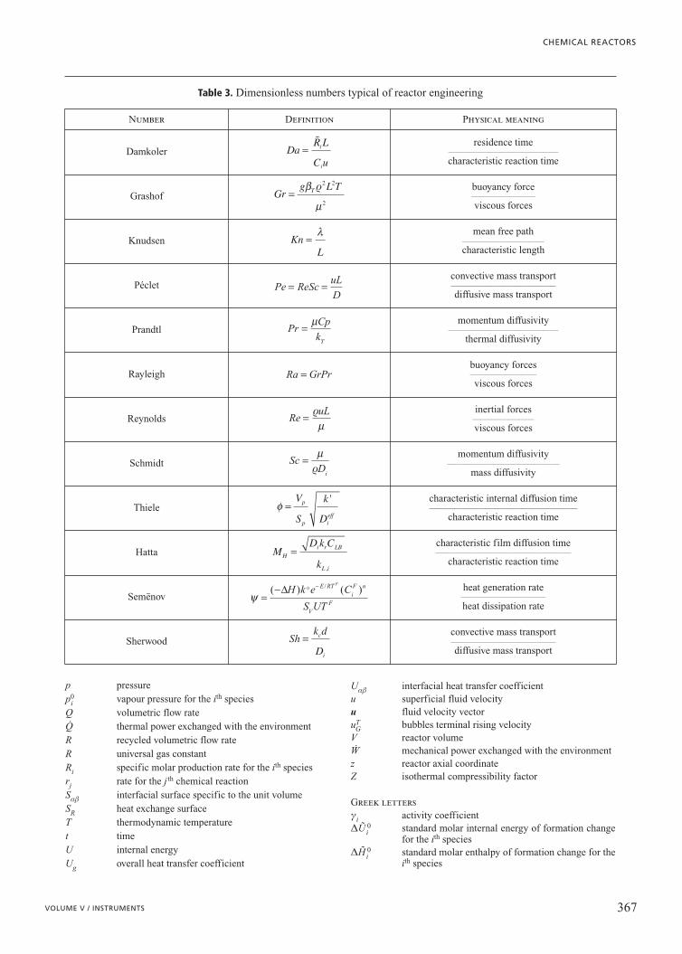
p pressurep0
i vapour pressure for the ith speciesQ volumetric flow rateQ.
thermal power exchanged with the environmentR recycled volumetric flow rateR universal gas constantRi specific molar production rate for the ith speciesrj rate for the j th chemical reactionSab interfacial surface specific to the unit volumeSR heat exchange surfaceT thermodynamic temperaturet timeU internal energyUg overall heat transfer coefficient
Uab interfacial heat transfer coefficientu superficial fluid velocityu fluid velocity vectoruT
G bubbles terminal rising velocityV reactor volumeW.
mechanical power exchanged with the environmentz reactor axial coordinateZ isothermal compressibility factor
Greek lettersgi activity coefficientDUi
0 standard molar internal energy of formation changefor the ith species
DHi0 standard molar enthalpy of formation change for the
ith species
CHEMICAL REACTORS
367VOLUME V / INSTRUMENTS
Table 3. Dimensionless numbers typical of reactor engineering
Number Definition Physical meaning
Damkoler DaR L
C ui
i
=� residence time
1111131111133
characteristic reaction time
Grashof Grg L TT=β
µ
r2 2
2
buoyancy force3331111133
viscous forces
Knudsen KnL
=λ mean free path
11331111133
characteristic length
Péclet Pe Sc uLD
= =Reconvective mass transport13333333333331133311133
diffusive mass transport
Prandtl Pr = µCpkT
momentum diffusivity1133333333331133311133
thermal diffusivity
Rayleigh Ra Gr= Prbuoyancy forces13333333311133
viscous forces
Reynolds Re = ruLµ
inertial forces333133311133
viscous forces
Schmidt ScDi
= µr
momentum diffusivity33313331111111133
mass diffusivity
Thiele φ =V
S
k
D
p
p ieff
' characteristic internal diffusion time3333331111133111111133
characteristic reaction time
Hatta MD k C
kH
i r LB
L i
=,
characteristic film diffusion time33333111133111111133
characteristic reaction time
Semënov ψ =− −( ) ( )/∆H k e C
S UT
E RTiF n
VF
F0 heat generation rate
333111111133
heat dissipation rate
Sherwood Shk d
Dc
i
= convective mass transport33333133111111133
diffusive mass transport
DUR, j0 standard molar internal energy change associated
with the jth chemical reactionDHR, j standard molar enthalpy change associated with the
jth chemical reactione bed void fractionh yield in the producth catalyst effectivenessnij stoichiometric coefficient for the ith species in the
jth reactionx reactant conversionr molar density/ Thiele’s moduleF volumetric flow rates ratio (exit/feed)f volumetric recycling ratio (recycled flow rate/feed
flow rate)� selectivity between the reaction productst residence timetta viscous stress tensor for the generic phase y Semënov’s numberW reactor cross section
SuperscriptsF feed conditions 0 initial conditions ˜ molar property e effective property
SubscriptsR reactor L liquid phaseG gaseous phase S solid phase e external fluid thermal vectormix mixture propertiesp particle
Maurizio Masi
Dipartimento di Chimica, Materiali e Ingegneria chimica ‘Giulio Natta’
Politecnico di MilanoMilano, Italy
PROCESS ENGINEERING ASPECTS
368 ENCYCLOPAEDIA OF HYDROCARBONS