
6.3 Advances in FHE Reliability - SEMI.ORG Doug Hackler.pdf · ” SoP Conversion Process. ......
16
Advances in Flexible Hybrid Electronics Reliability Doug Hackler President & CEO American Semiconductor This work sponsored in part by the Air Force Research Laboratory, Wright-Patterson AFB and Rapid Response Technology Office, under the programs Enabling Flexible Materials, Devices and Processes for Defense and Advanced FleX SoC Microcontroller.
Transcript of 6.3 Advances in FHE Reliability - SEMI.ORG Doug Hackler.pdf · ” SoP Conversion Process. ......
Advances in Flexible Hybrid Electronics Reliability
Doug HacklerPresident & CEO
American Semiconductor
This work sponsored in part by the Air Force Research Laboratory, Wright-Patterson AFB and Rapid Response Technology Office, under the programs Enabling Flexible Materials, Devices and
Processes for Defense and Advanced FleX SoC Microcontroller.

©2017 American Semiconductor, Inc. All rights reserved.
FleXform-MCU™
FleX-MCU™
FleX-ADC™
FleX-OpAmp™
Flexible Hybrid System“Combination of flexible printed
materials and flexible silicon-based ICs to create a new class of flexible
electronics.”
Printed ElectronicsLow Cost, R2R, Large Format
Printed Electronics• Sensors• Interconnects• Substrates• Displays
• Low Cost, Large Format• Roll-To-Roll, Screen, Inkjet Print,
…
What’s Flexible Hybrid Electronics?
2
Flexible FleX-ICsHigh Performance, High
Density
FleX-ICs• Sensor Signal Processing• Data Processing• Data Storage• Communications
• Low Cost, High Performance• Compatible with Printed Electronics• Foundry CMOS + FleX Processing
Molex flexible substrate American Semiconductor

©2017 American Semiconductor, Inc. All rights reserved. 3
Wafer Conversion Process
Wafers from Foundry
“FleX” SoP Conversion Process Assembly Contractor or Customer
American Semiconductor – Boise, ID

©2017 American Semiconductor, Inc. All rights reserved.
Why Flexible Chips?
• New Applications Internet of Things (IoT)WearablesStructural
• New RequirementsConformal and/or FlexibleUltra thinUltra light weight
• Improved ReliabilityNo Die CrackingReduced Breakage of Interconnects
4
Traditional Thinned Die Failures
FleX-IC
Traditionally Thinned Die
©2017 American Semiconductor, Inc. All rights reserved.
New FHE Test Procedures
5
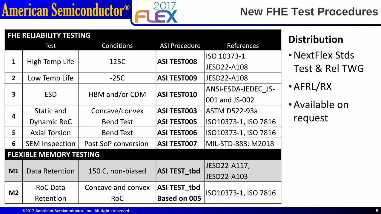
FHE RELIABILITY TESTINGTest Conditions ASI Procedure References
1 High Temp Life 125C ASI TEST008 ISO 10373-1JESD22-A108
2 Low Temp Life -25C ASI TEST009 JESD22-A108
3 ESD HBM and/or CDM ASI TEST010 ANSI-ESDA-JEDEC_JS-001 and JS-002
4Static and
Dynamic RoCConcave/convex
Bend TestASI TEST003 ASI TEST005
ASTM D522-93aISO10373-1, ISO 7816
5 Axial Torsion Bend Text ASI TEST006 ISO10373-1, ISO 78166 SEM Inspection Post SoP conversion ASI TEST007 MIL-STD-883: M2018
FLEXIBLE MEMORY TESTING
M1 Data Retention 150 C, non-biased ASI TEST_tbdJESD22-A117, JESD22-A103
M2RoC Data Retention
Concave and convex RoC
ASI TEST_tbdBased on 005
ISO10373-1, ISO 7816
Distribution • NextFlex Stds
Test & Rel TWG
• AFRL/RX
• Available on request

©2017 American Semiconductor, Inc. All rights reserved.
Radius of Curvature (RoC) TestingPer ASI Procedure TEST003
Testing Overview•Multiple die sizes: 2.2mm X 2.2mm → 5.0mm X 5.0mm•Bend die around precision mandrels until mechanical and/or electrical failure
•40 → 1 mm radius or curvature•Functional Electrical Test •Microscopic visual inspection for Mechanical failure •Minimum of 3 samples•Observed Failure methodsDie delamination from the substrateMaterials cracking
6
300um Die Delamination
20um Overcoat Cracking
FleX-IC at 1mm Radius
©2017 American Semiconductor, Inc. All rights reserved.
Radius of Curvature (RoC) TestingPer ASI Procedure TEST003
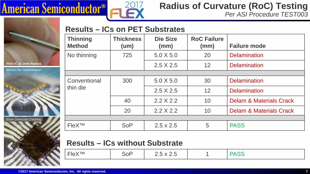
Results – ICs on PET Substrates
7
300um Die Delamination
20um Overcoat Cracking
FleX-IC at 1mm Radius
Thinning Method
Thickness(um)
Die Size(mm)
RoC Failure (mm) Failure mode
No thinning 725 5.0 X 5.0 20 Delamination
2.5 X 2.5 12 Delamination
Conventionalthin die
300 5.0 X 5.0 30 Delamination
2.5 X 2.5 12 Delamination
40 2.2 X 2.2 10 Delam & Materials Crack
20 2.2 X 2.2 10 Delam & Materials Crack
FleX™ SoP 2.5 x 2.5 5 PASS
Results – ICs without SubstrateFleX™ SoP 2.5 x 2.5 1 PASS
©2017 American Semiconductor, Inc. All rights reserved.
FHE Dynamic Reliability TestingPer ASI Procedure TEST003
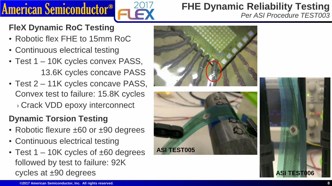
FleX Dynamic RoC Testing• Robotic flex FHE to 15mm RoC• Continuous electrical testing• Test 1 – 10K cycles convex PASS,
13.6K cycles concave PASS• Test 2 – 11K cycles concave PASS,
Convex test to failure: 15.8K cyclesCrack VDD epoxy interconnect
Dynamic Torsion Testing• Robotic flexure ±60 or ±90 degrees• Continuous electrical testing• Test 1 – 10K cycles of ±60 degrees
followed by test to failure: 92K cycles at ±90 degrees
8
ASI TEST005
ASI TEST006
©2017 American Semiconductor, Inc. All rights reserved.
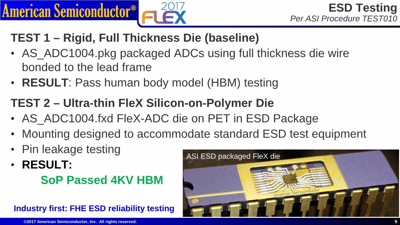
ESD TestingPer ASI Procedure TEST010
TEST 1 – Rigid, Full Thickness Die (baseline)• AS_ADC1004.pkg packaged ADCs using full thickness die wire
bonded to the lead frame • RESULT: Pass human body model (HBM) testing
TEST 2 – Ultra-thin FleX Silicon-on-Polymer Die• AS_ADC1004.fxd FleX-ADC die on PET in ESD Package• Mounting designed to accommodate standard ESD test equipment• Pin leakage testing• RESULT:
SoP Passed 4KV HBM
9
Industry first: FHE ESD reliability testing
ASI ESD packaged FleX die
©2017 American Semiconductor, Inc. All rights reserved.
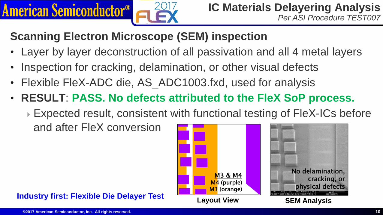
IC Materials Delayering AnalysisPer ASI Procedure TEST007
Scanning Electron Microscope (SEM) inspection • Layer by layer deconstruction of all passivation and all 4 metal layers• Inspection for cracking, delamination, or other visual defects • Flexible FleX-ADC die, AS_ADC1003.fxd, used for analysis• RESULT: PASS. No defects attributed to the FleX SoP process.Expected result, consistent with functional testing of FleX-ICs before
and after FleX conversion
10
Industry first: Flexible Die Delayer Test Layout View SEM Analysis
M3 & M4M4 (purple) M3 (orange)
No delamination, cracking, or
physical defects

©2017 American Semiconductor, Inc. All rights reserved.
HTOL and LTOL for FleX-IC DiePer ASI Procedures TEST008 and TEST009
HTOL Testing of FleX-IC Die• Passed 168 hours at 125C• Tested at 1, 24, 48, 72 and 168hrs
LTOL Testing of FleX-IC Die• Passed 168 hours at -25C• Tested at 1, 24, 48, 72 and 168hrs
Proprietary Information 11
FleX-IC Die in FreezerFleX-IC Die in Oven
Industry first: Flexible Die Lifetime Tests
©2017 American Semiconductor, Inc. All rights reserved.
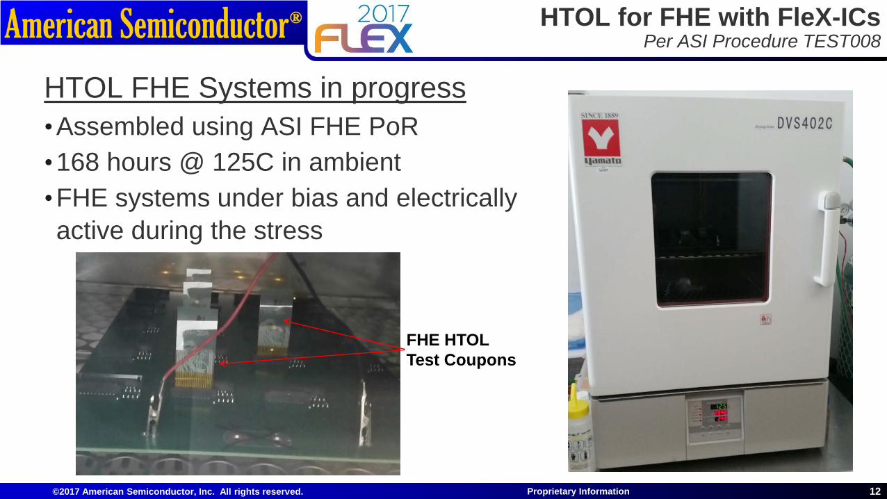
HTOL for FHE with FleX-ICsPer ASI Procedure TEST008
HTOL FHE Systems in progress•Assembled using ASI FHE PoR•168 hours @ 125C in ambient•FHE systems under bias and electrically active during the stress
12Proprietary Information
FHE HTOL Test Coupons

©2017 American Semiconductor, Inc. All rights reserved.
FleX-SoC™Programmable System on a Chip
Cypress CY8C20XX6A/S 8-bit Microcontroller Core 1.7 – 5.5V Operating Range Low Power, Including 0.1uA Deep Sleep 32KB (256Kb) Flash NVM 2KB SRAM USB 2.0 – 12Mbs Full-Speed Compliant 10-bit Analog-to-Digital Converter 2 Analog Comparators Low Power Sense Module 36 Programmable Input / Output Pins 6/12/24MHz Internal Oscillator
13SBIR Data Rights
FleX-SoC Die 2.16 x 2.28mm
Features:

©2017 American Semiconductor, Inc. All rights reserved.
FleX Non-Volatile Memory Radius of Curvature Testing
14SBIR Data Rights
1.0E-12
1.0E-11
1.0E-10
1.0E-09
1.0E-08
1.0E-07
1.0E-06
1.0E-05
1.0E-04
-3.0 -2.0 -1.0 0.0 1.0 2.0 3.0
Idra
in (A
)
Vgate (V)
FleX Non-Volatile Memory Radius of Curvature Testing
SONOS Programed No RoC W=25u L=25u SONOS Programed 40mm RoC W=25u L=25u SONOS Programed 20mm RoC W=25u L=25u SONOS Programed 10mm RoC W=25u L=25u SONOS Programed 5mm RoC W=25u L=25u SONOS Programed -40mm RoC W=25u L=25u SONOS Programed -20mm RoC W=25u L=25u SONOS Programed -10mm RoC W=25u L=25u SONOS Programed -5mm RoC W=25u L=25u
SONOS Erased No RoC W=25u L=25u SONOS Erased 40mm RoC W=25u L=25u SONOS Erased 20mm RoC W=25u L=25u SONOS Erased 10mm RoC W=25u L=25u SONOS Erased 5mm RoC W=25u L=25u SONOS Erased -40mm RoC W=25u L=25u SONOS Erased -20mm RoC W=25u L=25u SONOS Erased -10mm RoC W=25u L=25u SONOS Erased -5mm RoC W=25u L=25u
PassPass
• First demo of a flexible, high density non-volatile memory elementData retention demonstrated successfully down to 5mm RoC (convex and concave)

©2017 American Semiconductor, Inc. All rights reserved.
FleX-SoC NVM Data Retention Testing
• Flash NVM high temp data retention passed 500hrs @ 150C
• AFRL/RX Flash NVM Solar Irradiance Testing –Pass: Data retention testing at AFRL/RX Oriel solar simulator Air Mass AM 1.5G 100mW cm2 solar simulated illumination Class B for spectral match, irradiance spatial non-
uniformity, andtemporal instability
300mW full spectrum Calibrated to a KG-5 filtered Si reference cell Passed 8 hours exposure
15

Thank You
American Semiconductor, Inc.6987 W Targee St
Boise, ID 83709Tel: 208.336.2773Fax: 208.336.2752
www.americansemi.com
© 2017 American Semiconductor, Inc. All rights reserved.American Semiconductor is a registered trademark of American Semiconductor, Inc. FleXform, FleXform-ADC, FleX, Silicon-on-Polymer, FleX-ADC, FleX-MCU and FleX-IC are trademarks of American Semiconductor, Inc.
Doug [email protected]
+1 208-336-2773


