62xeumxvxxx-ab 13.05.02 - 7442frankshospitalworkshop.com/equipment/documents/autoclaves/user... ·...
31
D:\e\VERT2\62XEUMXVXXX-Vakuumpumpe\62xeumxvxxx-ab 13.05.02 - 7442\62xeumxvxxx-ab 13.05.02 - 7442.pdf 1 OPERATING INSTRUCTIONS for vertical autoclave KSG 40/60-2 KSG 50/70-2 KSG 50/80-2 KSG 50/95-2 double-walled execution with sterilization timer and electric motor vacuum pump for sterilization of hospital utensils as instruments, laundry and rubber goods Modifications reserved. 10.07.06 62XEUMXV.XXX S-No. XXXX Electric diagram 01E040602EUV001 (2000-4) Piping diagram 1417-4 KSG Sterilisatoren GmbH Buchhoferstraße 5 82140 Olching Federal Republic of Germany Phone: +49-8142 / 2957-0 Fax: +49-8142 / 40384 E-mail: [email protected]
Transcript of 62xeumxvxxx-ab 13.05.02 - 7442frankshospitalworkshop.com/equipment/documents/autoclaves/user... ·...
D:\e\VERT2\62XEUMXVXXX-Vakuumpumpe\62xeumxvxxx-ab 13.05.02 - 7442\62xeumxvxxx-ab 13.05.02 - 7442.pdf 1
OPERATING INSTRUCTIONS
for vertical autoclave
KSG 40/60-2 KSG 50/70-2 KSG 50/80-2 KSG 50/95-2
double-walled execution
with sterilization timer
and
electric motor vacuum pump
for sterilization of hospital utensils as instruments, laundry and rubber goods
Modifications reserved. 10.07.06 62XEUMXV.XXX S-No. XXXX Electric diagram 01E040602EUV001 (2000-4) Piping diagram 1417-4
KSG Sterilisatoren GmbH Buchhoferstraße 5 82140 Olching Federal Republic of Germany Phone: +49-8142 / 2957-0 Fax: +49-8142 / 40384 E-mail: [email protected]
D:\e\VERT2\62XEUMXVXXX-Vakuumpumpe\62xeumxvxxx-ab 13.05.02 - 7442\62xeumxvxxx-ab 13.05.02 - 7442.pdf 2
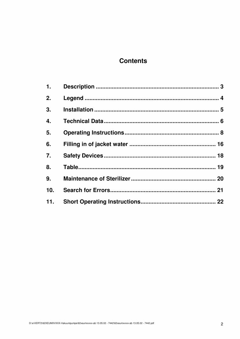
Contents
1. Description ............................................................................. 3
2. Legend .................................................................................... 4
3. Installation .............................................................................. 5
4. Technical Data........................................................................ 6
5. Operating Instructions........................................................... 8
6. Filling in of jacket water ...................................................... 16
7. Safety Devices ...................................................................... 18
8. Table...................................................................................... 19
9. Maintenance of Sterilizer ..................................................... 20
10. Search for Errors.................................................................. 21
11. Short Operating Instructions............................................... 22
D:\e\VERT2\62XEUMXVXXX-Vakuumpumpe\62xeumxvxxx-ab 13.05.02 - 7442\62xeumxvxxx-ab 13.05.02 - 7442.pdf 3
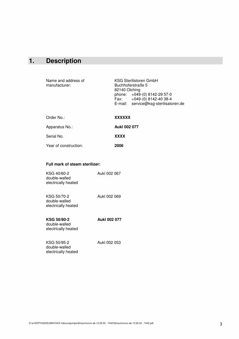
1. Description Name and address of KSG Sterilistoren GmbH manufacturer: Buchhoferstraße 5 82140 Olching phone: +049-(0) 8142-29 57-0 Fax: +049-(0) 8142-40 38-4 E-mail: [email protected] Order No.: XXXXXX Apparatus No.: Aukl 002 077 Serial No. XXXX Year of construction: 2006 Full mark of steam sterilizer: KSG 40/60-2 Aukl 002 067 double-walled electrically heated KSG 50/70-2 Aukl 002 069 double-walled electrically heated KSG 50/80-2 Aukl 002 077 double-walled electrically heated KSG 50/95-2 Aukl 002 053 double-walled electrically heated
D:\e\VERT2\62XEUMXVXXX-Vakuumpumpe\62xeumxvxxx-ab 13.05.02 - 7442\62xeumxvxxx-ab 13.05.02 - 7442.pdf 4
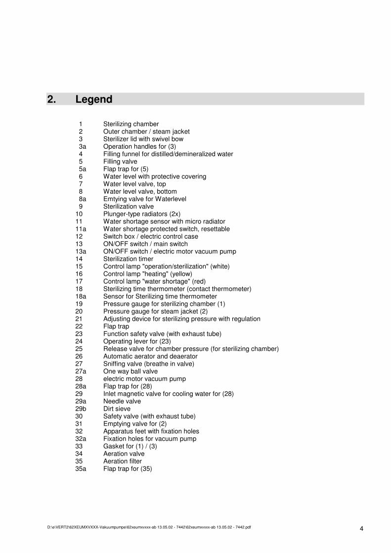
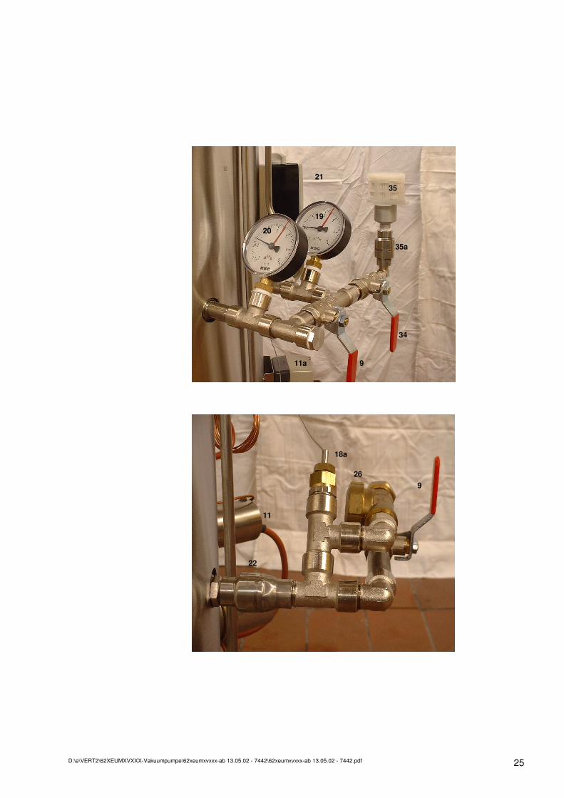
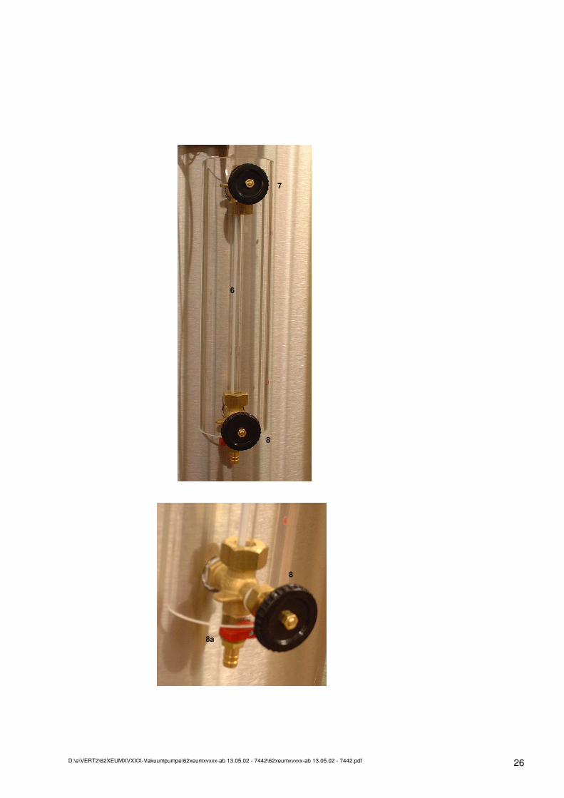
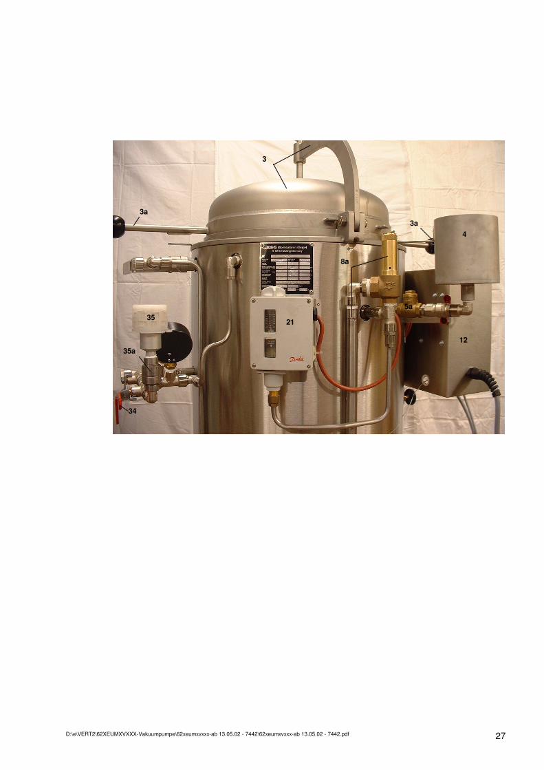
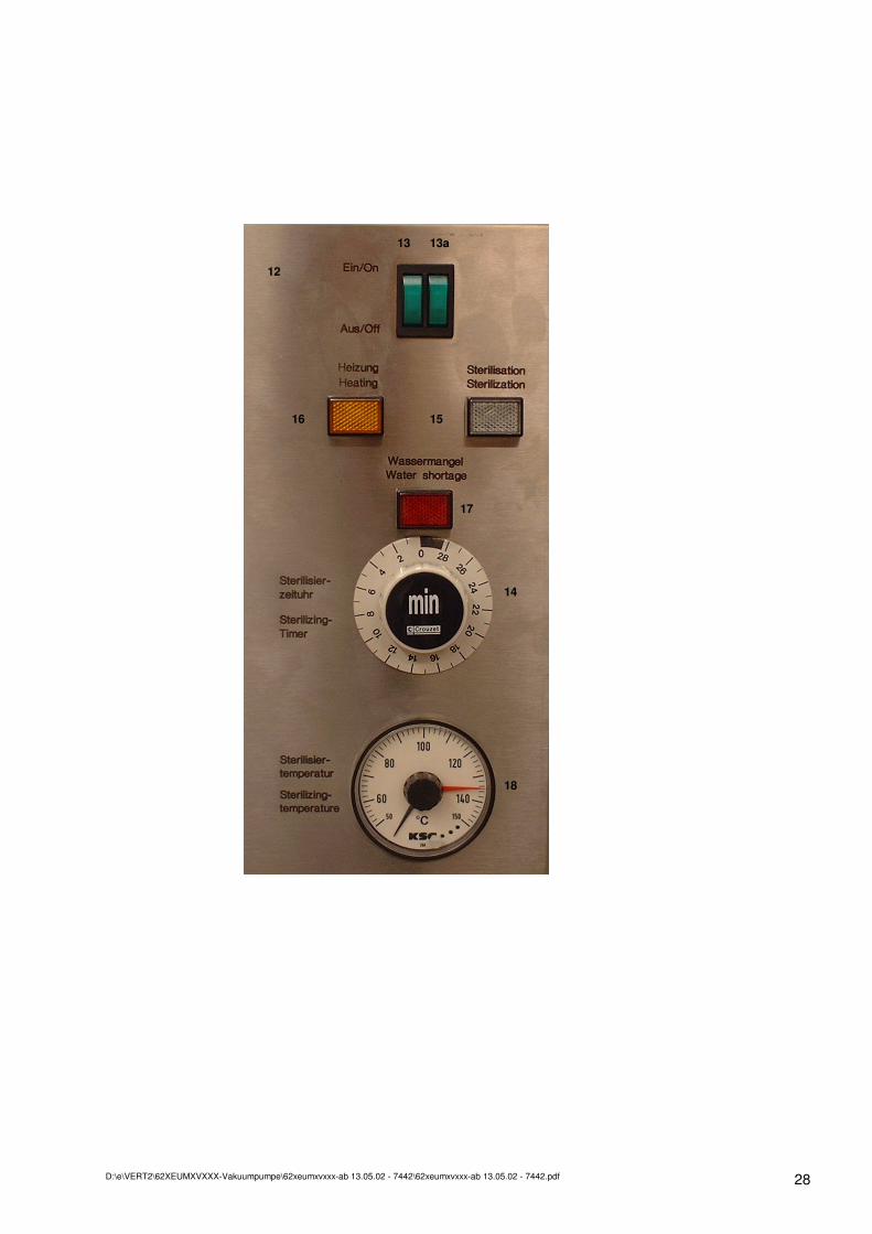
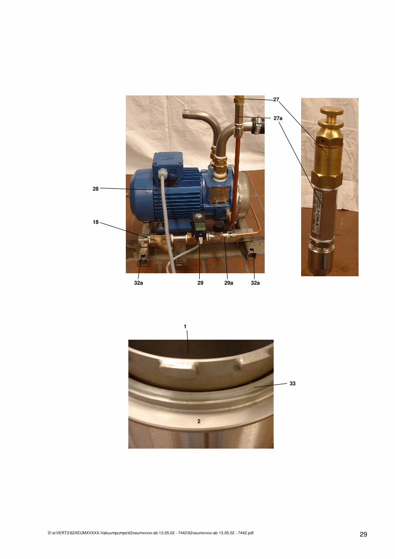
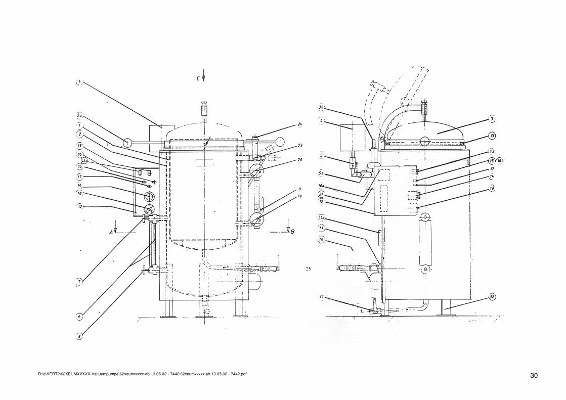
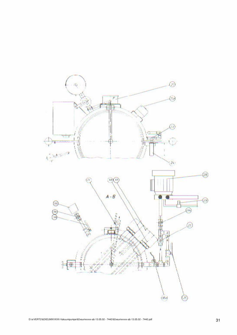
2. Legend 1 Sterilizing chamber 2 Outer chamber / steam jacket 3 Sterilizer lid with swivel bow 3a Operation handles for (3) 4 Filling funnel for distilled/demineralized water 5 Filling valve 5a Flap trap for (5) 6 Water level with protective covering 7 Water level valve, top 8 Water level valve, bottom 8a Emtying valve for Waterlevel 9 Sterilization valve 10 Plunger-type radiators (2x) 11 Water shortage sensor with micro radiator 11a Water shortage protected switch, resettable 12 Switch box / electric control case 13 ON/OFF switch / main switch 13a ON/OFF switch / electric motor vacuum pump 14 Sterilization timer 15 Control lamp "operation/sterilization" (white) 16 Control lamp "heating" (yellow) 17 Control lamp "water shortage" (red) 18 Sterilizing time thermometer (contact thermometer) 18a Sensor for Sterilizing time thermometer 19 Pressure gauge for sterilizing chamber (1) 20 Pressure gauge for steam jacket (2) 21 Adjusting device for sterilizing pressure with regulation 22 Flap trap 23 Function safety valve (with exhaust tube) 24 Operating lever for (23) 25 Release valve for chamber pressure (for sterilizing chamber) 26 Automatic aerator and deaerator 27 Sniffing valve (breathe in valve) 27a One way ball valve 28 electric motor vacuum pump 28a Flap trap for (28) 29 Inlet magnetic valve for cooling water for (28) 29a Needle valve 29b Dirt sieve 30 Safety valve (with exhaust tube) 31 Emptying valve for (2) 32 Apparatus feet with fixation holes 32a Fixation holes for vacuum pump 33 Gasket for (1) / (3) 34 Aeration valve 35 Aeration filter 35a Flap trap for (35)
D:\e\VERT2\62XEUMXVXXX-Vakuumpumpe\62xeumxvxxx-ab 13.05.02 - 7442\62xeumxvxxx-ab 13.05.02 - 7442.pdf 5
3. Installation
3.1. General Remarks
3.1.1. Read the operating instructions before setting the apparatus into operation.
3.1.2. Take care that power supply is in accordance with regulations.
3.1.3. Take care that electric supply satisfies the valid regulations on site, see name plate.
3.1.4. Take care that the electric power supply satisfies the valid regulations on site. Attention: Main switch to be installed on site
3.1.5. Take care for cold water connection for electric motor vacuum pump (28) at the electromagnetic valve (29).
3.1.6. Take care that under the sterilizer there is a water outlet (e.g. gully) for the waste pipes of the sterilizer.
3.1.7. To guarantee the stability of the sterilizer, the apparatus feet (32) have to be fixed to the ground.
3.1.8. If the sterilizer is not used, close the water inlet valve for cooling water (29).
D:\e\VERT2\62XEUMXVXXX-Vakuumpumpe\62xeumxvxxx-ab 13.05.02 - 7442\62xeumxvxxx-ab 13.05.02 - 7442.pdf 6
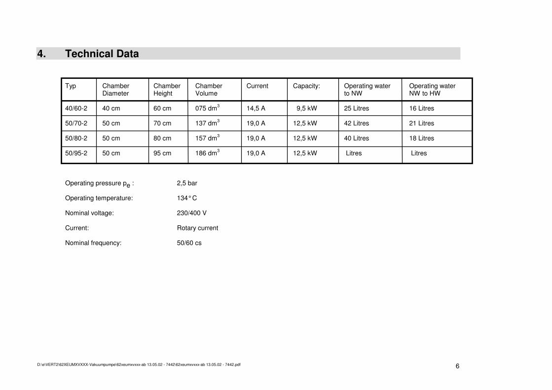
4. Technical Data Typ Chamber Chamber Chamber Current Capacity: Operating water Operating water Diameter Height Volume to NW NW to HW 40/60-2 40 cm 60 cm 075 dm3 14,5 A 9,5 kW 25 Litres 16 Litres 50/70-2 50 cm 70 cm 137 dm3 19,0 A 12,5 kW 42 Litres 21 Litres 50/80-2 50 cm 80 cm 157 dm3 19,0 A 12,5 kW 40 Litres 18 Litres 50/95-2 50 cm 95 cm 186 dm3 19,0 A 12,5 kW Litres Litres Operating pressure pe : 2,5 bar Operating temperature: 134° C Nominal voltage: 230/400 V Current: Rotary current Nominal frequency: 50/60 cs
D:\e\VERT2\62XEUMXVXXX-Vakuumpumpe\62xeumxvxxx-ab 13.05.02 - 7442\62xeumxvxxx-ab 13.05.02 - 7442.pdf 7
4.1. General Remarks Feeding water: For operation of the sterilizer either distilled, demineralized or completely desalted water is necessary. Indications concerning the filling quantity of operating water for steam jacket in case of empty chamber until min. water level (NW) and from minimum water level (NW) to max. level (HW) can be taken from paragraph 4. Technical data. The switchboard with command, operating and indicating elements (12 - 18) makes it possible to operate the sterilizer acc. to the operating instructions and the control of the programme cycle. Two radiators (10). Water shortage sensor (11) with micro heating element 0,5 kW and water shortage protected switch (11a), resettable. Regulator and adjustor for sterilization pressure (21), max. 2,5 bar.
D:\e\VERT2\62XEUMXVXXX-Vakuumpumpe\62xeumxvxxx-ab 13.05.02 - 7442\62xeumxvxxx-ab 13.05.02 - 7442.pdf 8
5. Operating Instructions For setting the sterilizer into operation, please proceed as follows:
5.1. Control of feeding water Level of feeding water at the water level glass (distilled or demineralized water) has to be between the markings for minimum and maximum water level. Should this not be the case, the outer chamber (2) has to be filled with a corresponding quantity of water. This can only be done when the outer chamber (2) is without pressure resp. cold, i.e. the pressure gauge for the steam jacket (20) indicates "0" bar.
5.2. Filling in of water for first filling of after having emptied the jacket completely
5.2.1. Open the sterilization valve (9).
5.2.2. Open the function safety valve (23) by means of the operating lever (24), if the sterilizer lid (3) is closed.
5.2.3. Open the filling valve (5).
5.2.4. Fill in distilled or demineralized water into the filling funnel (4) until water level (6) has reached the maximum marking.
5.2.5. Close the filling valve (5).
5.2.6. Close the sterilization valve (9).
D:\e\VERT2\62XEUMXVXXX-Vakuumpumpe\62xeumxvxxx-ab 13.05.02 - 7442\62xeumxvxxx-ab 13.05.02 - 7442.pdf 9
5.3. Heating / preheating of the sterilizer The saturated steam necessary for sterilization is produced in the steam jacket (2) by means of two electric radiators (10). To start the heating process, please proceed as follows:
5.3.1. Control the water level at the water level indication (6).
5.3.2. Control that filling valve (5) and sterilization valve (9) are closed.
5.3.3. Adjust the sterilizing pressure on the adjusting device (21) as shown in table 8.
5.3.4. Press ON/OFF switch (13) to "ON"-position (control lamp lights green).
5.3.5. Now the initiated heating process lasts approx. 30 - 35 min., when there is maximum water level and maximum required pressure, until the necessary steam pressure is reached. As long as the operating pressure is not reached, heating is in operation. This can be seen by the lighting of the yellow control lamp "heating" (16).
5.3.6. The process of preheating is finished when the pressure gauge for the steam jacket (20) indicates the pressure preselected on the adjusting device for sterilizing pressure and the yellow control lamp "heating" (16) goes out for the first time. Now the apparatus is ready for sterilization.
D:\e\VERT2\62XEUMXVXXX-Vakuumpumpe\62xeumxvxxx-ab 13.05.02 - 7442\62xeumxvxxx-ab 13.05.02 - 7442.pdf 10
5.4. Loading of the sterilizer
5.4.1. Please classify the sterilizing goods acc. to sterilizing temperature and time (see table 8).
5.4.2. If necessary/scheduled, put the sterilizing goods into the provided packages/boxes (accessories).
5.4.3. Place the sterilizing goods into the sterilizing chamber (1) and put them on the ground plate resp. on the trays (accessories). The chamber can be filled up until its upper edge.
5.5. Close sterilizing lid
5.5.1. To that end turn the lid by the operating handles (3a) counter-clockwise until the limit stop.
5.5.2. Then tilt the lid downwards until it lies on the gasket (33).
5.5.3. Afterwards please turn the lid by means of the operating handles (3a) in clockwise direction until the limit stop. The lid is closed properly when the red markings (22) are one above each other.
5.5.4. At last close the function safety valve (23) with the operating lever (24). This process is executed properly when the lever (24) is situated in the intended groove of the link of the operating handle. Attention: Only by this procedure it is secured that the chamber lid and the function safety
valve are closed orderly and pressure in the sterilizing chamber can be produced after opening the sterilization valve.
D:\e\VERT2\62XEUMXVXXX-Vakuumpumpe\62xeumxvxxx-ab 13.05.02 - 7442\62xeumxvxxx-ab 13.05.02 - 7442.pdf 11
5.6. Pre vacuum for Solids To prepare the sterilizing chamber and the goods for the following sterilizing process, an evacuation of the air from the sterilizing chamber and the goods can be executed. Please open the release valve for chamber pressure (25) and then press switch (13a) for setting the electric motor vacuum pump (28) and the cold water magnetic valve (29) into operation. The efficiency is depending on the vacuum influence time, the height of the achieved vacuum, the quantity of vacuums (fractionated vacuum) and the type of goods to be sterilized. To finish the process of evacuation close the release valve for chamber pressure (25) and switch off the vacuum pump (28) and the cold water magnetic valve (29) by actuating switch (13a) again.
5.7. Fractionated Vacuum for Solids Especially for porous goods, as textiles, it is necessary to have a good air removal from the chamber and the goods to be sterilized before sterilization. This can be achieved by the repeated use of the vacuum pump (evacuation) alternating with steam pushes. Please proceed several times acc. to points 5.8 and 5.8.5. Start with evacuation of chamber (5.8) and go on with closing the hand valve (25) and careful opening of the sterilization valve (9). Take into consideration: The higher the achieved low pressure is during evacuation, the better the air dilution factor. The value of steam push should be 1100 - 1500 mlb (point 5.8.5).

D:\e\VERT2\62XEUMXVXXX-Vakuumpumpe\62xeumxvxxx-ab 13.05.02 - 7442\62xeumxvxxx-ab 13.05.02 - 7442.pdf 12
5.8. Sterilizing programmes
5.8.1. Turn the sterilizing timer (14) in clockwise direction to the necessary sterilizing time, acc. to table 8. Remark: a) The timer only counts the sterilizing time when the sterilizing cycle is running and the
necessary temperature resp. the necessary steam pressure is available. b) You can see the necessary time for a proper sterilizing cycle at the time indicatiton of the
timer, if the timer has been adjusted acc. to sterilizing goods and table 8.
5.8.2. Before the sterilization process starts, control the adjustment of the sterilizing pressure (21). Compare the pressure of the outer chamber at the pressure gauge for jacket (20) (actual value) when the control lamp "Heating" (16) is extinguished with the set value acc. to table 8 for the goods to be sterilized and adjust it at the regulator (21), if necessary.
5.8.3. Adjust the sterilizing temperature acc. to table 8 at the contact thermometer (18).
5.8.4. Control the release valve for chamber pressure (25) and close it, if still open.
5.8.5. When the necessary operating pressure is reached in the outer jacket (to be seen at the pressure gauge for jacket (20)), open the sterilization valve (9). The heating-up time starts. Steam flows from steam jacket (2) into the sterilizing chamber (1). This procedure can be seen by the increasing indication of the pressure gauge for the sterilizing chamber (19). The temperature of the sterilizing chamber is also increasing, indicated on the sterilization thermometer (18) by means of the temperature sensor (18a). Remark: a) When steam flows from steam jacket (2) into sterilizing chamber (1), the pressure in the
outer chamber decreases - to be seen at the pressure gauge of the outer chamber (20). Via the adjusting device for sterilizing pressure (21) the radiators are switched on automatically - to be seen at the yellow control lamp "heating" (16).
b) As soon as the sterilizing thermometer (18) has reached the required sterilizing temperature,
sterilizing time begins to run down. c) The air in the sterilizing chamber is displaced by the entering steam and is led off via the
automatic aerator and deaerator (26). At a temperature of 100° C and higher, this component is closed, thus rendering possible that the steam pressure of the sterilizing chamber is reduced. The heating-up is finished, when the adjusted temperature is reached.
D:\e\VERT2\62XEUMXVXXX-Vakuumpumpe\62xeumxvxxx-ab 13.05.02 - 7442\62xeumxvxxx-ab 13.05.02 - 7442.pdf 13
5.8.6. The sterilizing phase is indicated by the white control lamp "Sterilization" (11). In this phase the heating (10) is switched off and the sterilizing timer (14) is in operation. When the chamber temperature is lower than the value adjusted at the contact thermometer (18), the sterilizing timer (14) is switched off, the white control lamp "Sterilization" (15) goes out and the yellow control lamp "Heating" (16) is illuminated, while the heating elements (10) are again in operation until the sterilizing temperature is reached again. This change is repeated until the sterilizing time (sterilizing timer) (14) has run down. This working method secures that the sterilizing timer (14) only measures the real sterilizing time resp. that the goods to be sterilized are subject to the adjusted temperature for the complete time adjusted at the timer. Attention: The sterilizer lid is hot during operation !
D:\e\VERT2\62XEUMXVXXX-Vakuumpumpe\62xeumxvxxx-ab 13.05.02 - 7442\62xeumxvxxx-ab 13.05.02 - 7442.pdf 14
5.9. End of programme After the end of the sterilizing time - indication "0" min. at the sterilization timer (14) - the sterilizing programme is finished.
5.9.1. The sterilization valve (9) has to be closed now. Thus the steam flow between outer chamber (2) and sterilizing chamber (1) is interrupted. The separation of both chambers (1 and 2) permits that the sterile goods can be removed from the chamber (1) while in the outer chamber the operating pressure is maintained for a further cycle.
5.10. Pressure reduction in the sterilizing chamber Pressure reduction in the sterilizing chamber (1) can be executed by different methods, acc. to the requirements (see table 8):
5.10.1. By self-cooling of the complete sterilizer, where the unit is switched off at the on/off-switch (13) and left in this condition until the pressure of the sterilizing chamber (1) is 0 bar - to be seen at the pressure gauge for the sterilizing chamber (19).
5.10.2. By vacuum drying, i.e. you first close the sterilizing valve (9). Press switch (13a) for setting the electric motor vacuum pump (28) and the cold water magnetic valve (29) into operation. Afterwards open the release valve for chamber pressure (25) carefully. By this method the steam is pressed away by the inner pressure in the chamber. Then the sterile goods are dried by the vacuum produced by electric motor vacuum pump. The degree of drying depends on the vacuum influence time, the height of the achieved vacuum and the type of goods.
5.10.3. For ending the vacuum drying process close the hand valve release valve for chamber pressure (25) and switch off the vacuum pump and the cold water magnetic valve (29) by actuating switch (13a) again. Pressure equalization in the chamber is reached by opening the ventilation valve (34) - indication "0" bar at the pressure gauge for the sterilizing chamber (19).
D:\e\VERT2\62XEUMXVXXX-Vakuumpumpe\62xeumxvxxx-ab 13.05.02 - 7442\62xeumxvxxx-ab 13.05.02 - 7442.pdf 15
5.11. Open the sterilizer lid
5.11.1. The sterilizer lid (3) may only be opened when the sterilizing chamber is pressureless and the sterilizing valve (9) is closed - Indication "0" bar at the pressure gauge for chamber (25).
5.11.2. For that purpose the function safety valve (23) is opened with the operation lever (24). The eventually remaining overpressure now escapes from the sterilizing chamber. Attention: It is still possible that steam escapes at the exhaust tube of this valve.
5.11.3. By means of the operation handles the lid is turned until the limit stop and then opened. Attention: It is still possible that hot steam escapes from the sterilizing chamber.
5.11.4. Now the - possibly still hot - sterile goods can be removed.
5.12. Preparations for further sterilizations After the chamber has been emptied, the sterilizer can quickly be prepared for the next charge, when is has been operated with rapid steam reduction or vacuum drying. If you have effected the sterilization with self-radiation, the outer chamber (2) must again be set into operation.
5.13. Switching off of sterilizer For final switching off of the sterilizer, e.g. after the last load of the day, the ON/OFF switch (13) has to be switched off (green light goes out) and the main cock has to be closed.
D:\e\VERT2\62XEUMXVXXX-Vakuumpumpe\62xeumxvxxx-ab 13.05.02 - 7442\62xeumxvxxx-ab 13.05.02 - 7442.pdf 16
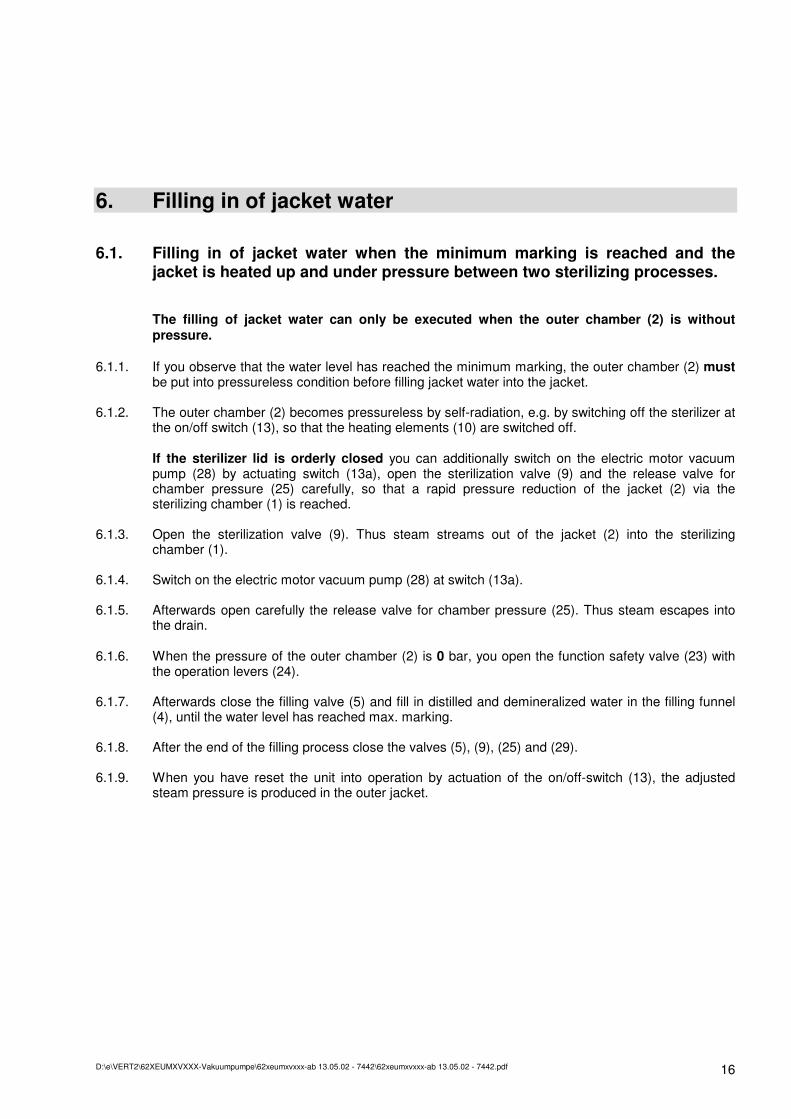
6. Filling in of jacket water
6.1. Filling in of jacket water when the minimum marking is reached and the jacket is heated up and under pressure between two sterilizing processes. The filling of jacket water can only be executed when the outer chamber (2) is without pressure.
6.1.1. If you observe that the water level has reached the minimum marking, the outer chamber (2) must be put into pressureless condition before filling jacket water into the jacket.
6.1.2. The outer chamber (2) becomes pressureless by self-radiation, e.g. by switching off the sterilizer at the on/off switch (13), so that the heating elements (10) are switched off. If the sterilizer lid is orderly closed you can additionally switch on the electric motor vacuum pump (28) by actuating switch (13a), open the sterilization valve (9) and the release valve for chamber pressure (25) carefully, so that a rapid pressure reduction of the jacket (2) via the sterilizing chamber (1) is reached.
6.1.3. Open the sterilization valve (9). Thus steam streams out of the jacket (2) into the sterilizing chamber (1).
6.1.4. Switch on the electric motor vacuum pump (28) at switch (13a).
6.1.5. Afterwards open carefully the release valve for chamber pressure (25). Thus steam escapes into the drain.
6.1.6. When the pressure of the outer chamber (2) is 0 bar, you open the function safety valve (23) with the operation levers (24).
6.1.7. Afterwards close the filling valve (5) and fill in distilled and demineralized water in the filling funnel (4), until the water level has reached max. marking.
6.1.8. After the end of the filling process close the valves (5), (9), (25) and (29).
6.1.9. When you have reset the unit into operation by actuation of the on/off-switch (13), the adjusted steam pressure is produced in the outer jacket.
D:\e\VERT2\62XEUMXVXXX-Vakuumpumpe\62xeumxvxxx-ab 13.05.02 - 7442\62xeumxvxxx-ab 13.05.02 - 7442.pdf 17
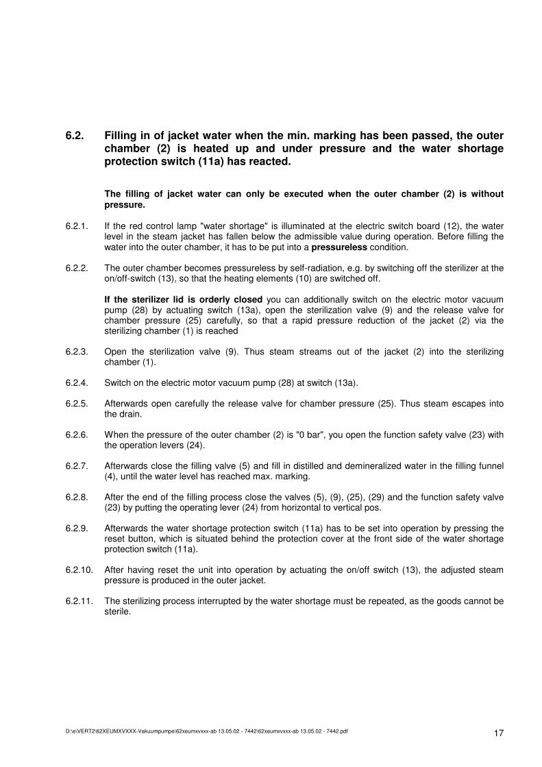
6.2. Filling in of jacket water when the min. marking has been passed, the outer chamber (2) is heated up and under pressure and the water shortage protection switch (11a) has reacted.
The filling of jacket water can only be executed when the outer chamber (2) is without pressure.
6.2.1. If the red control lamp "water shortage" is illuminated at the electric switch board (12), the water
level in the steam jacket has fallen below the admissible value during operation. Before filling the water into the outer chamber, it has to be put into a pressureless condition.
6.2.2. The outer chamber becomes pressureless by self-radiation, e.g. by switching off the sterilizer at the on/off-switch (13), so that the heating elements (10) are switched off. If the sterilizer lid is orderly closed you can additionally switch on the electric motor vacuum pump (28) by actuating switch (13a), open the sterilization valve (9) and the release valve for chamber pressure (25) carefully, so that a rapid pressure reduction of the jacket (2) via the sterilizing chamber (1) is reached
6.2.3. Open the sterilization valve (9). Thus steam streams out of the jacket (2) into the sterilizing chamber (1).
6.2.4. Switch on the electric motor vacuum pump (28) at switch (13a).
6.2.5. Afterwards open carefully the release valve for chamber pressure (25). Thus steam escapes into the drain.
6.2.6. When the pressure of the outer chamber (2) is "0 bar", you open the function safety valve (23) with the operation levers (24).
6.2.7. Afterwards close the filling valve (5) and fill in distilled and demineralized water in the filling funnel (4), until the water level has reached max. marking.
6.2.8. After the end of the filling process close the valves (5), (9), (25), (29) and the function safety valve (23) by putting the operating lever (24) from horizontal to vertical pos.
6.2.9. Afterwards the water shortage protection switch (11a) has to be set into operation by pressing the reset button, which is situated behind the protection cover at the front side of the water shortage protection switch (11a).
6.2.10. After having reset the unit into operation by actuating the on/off switch (13), the adjusted steam pressure is produced in the outer jacket.
6.2.11. The sterilizing process interrupted by the water shortage must be repeated, as the goods cannot be sterile.
D:\e\VERT2\62XEUMXVXXX-Vakuumpumpe\62xeumxvxxx-ab 13.05.02 - 7442\62xeumxvxxx-ab 13.05.02 - 7442.pdf 18
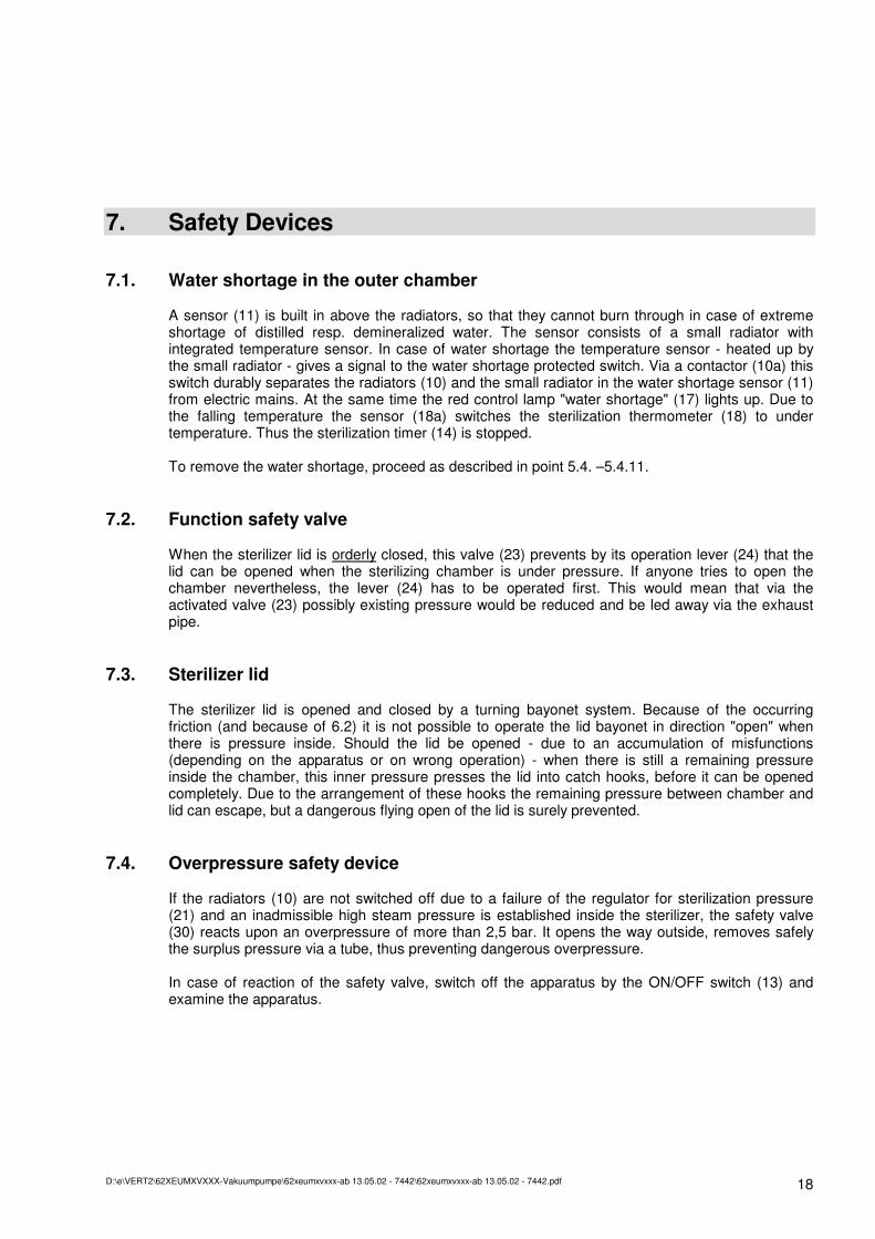
7. Safety Devices
7.1. Water shortage in the outer chamber A sensor (11) is built in above the radiators, so that they cannot burn through in case of extreme shortage of distilled resp. demineralized water. The sensor consists of a small radiator with integrated temperature sensor. In case of water shortage the temperature sensor - heated up by the small radiator - gives a signal to the water shortage protected switch. Via a contactor (10a) this switch durably separates the radiators (10) and the small radiator in the water shortage sensor (11) from electric mains. At the same time the red control lamp "water shortage" (17) lights up. Due to the falling temperature the sensor (18a) switches the sterilization thermometer (18) to under temperature. Thus the sterilization timer (14) is stopped. To remove the water shortage, proceed as described in point 5.4. –5.4.11.
7.2. Function safety valve When the sterilizer lid is orderly closed, this valve (23) prevents by its operation lever (24) that the lid can be opened when the sterilizing chamber is under pressure. If anyone tries to open the chamber nevertheless, the lever (24) has to be operated first. This would mean that via the activated valve (23) possibly existing pressure would be reduced and be led away via the exhaust pipe.
7.3. Sterilizer lid The sterilizer lid is opened and closed by a turning bayonet system. Because of the occurring friction (and because of 6.2) it is not possible to operate the lid bayonet in direction "open" when there is pressure inside. Should the lid be opened - due to an accumulation of misfunctions (depending on the apparatus or on wrong operation) - when there is still a remaining pressure inside the chamber, this inner pressure presses the lid into catch hooks, before it can be opened completely. Due to the arrangement of these hooks the remaining pressure between chamber and lid can escape, but a dangerous flying open of the lid is surely prevented.
7.4. Overpressure safety device If the radiators (10) are not switched off due to a failure of the regulator for sterilization pressure (21) and an inadmissible high steam pressure is established inside the sterilizer, the safety valve (30) reacts upon an overpressure of more than 2,5 bar. It opens the way outside, removes safely the surplus pressure via a tube, thus preventing dangerous overpressure. In case of reaction of the safety valve, switch off the apparatus by the ON/OFF switch (13) and examine the apparatus.
D:\e\VERT2\62XEUMXVXXX-Vakuumpumpe\62xeumxvxxx-ab 13.05.02 - 7442\62xeumxvxxx-ab 13.05.02 - 7442.pdf 19
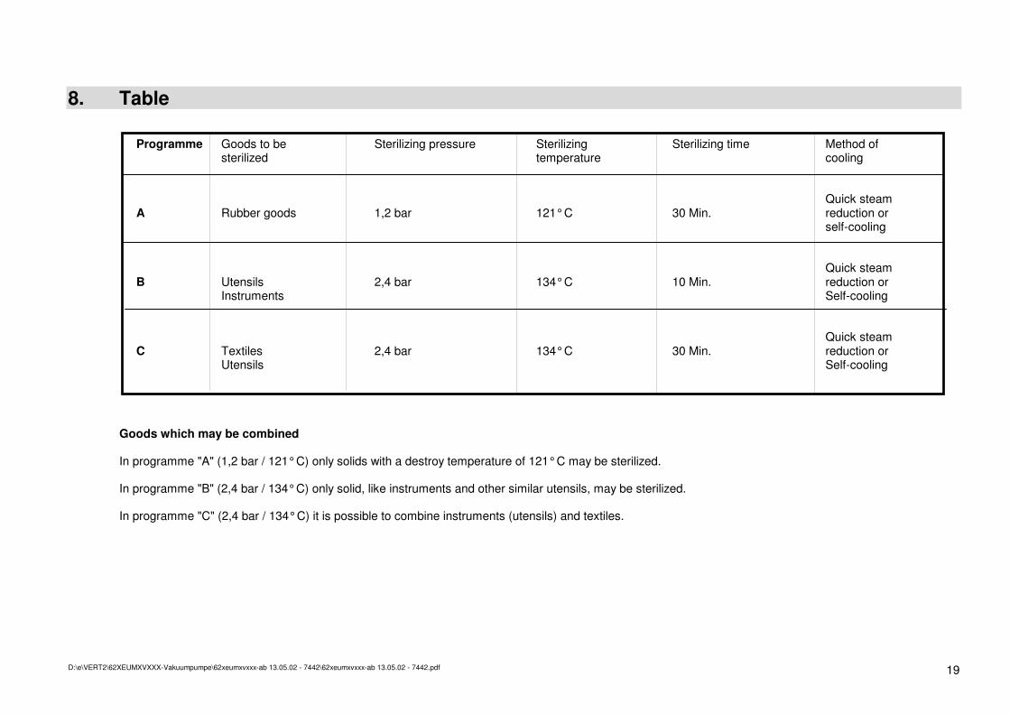
8. Table Programme Goods to be Sterilizing pressure Sterilizing Sterilizing time Method of sterilized temperature cooling Quick steam A Rubber goods 1,2 bar 121° C 30 Min. reduction or self-cooling Quick steam B Utensils 2,4 bar 134° C 10 Min. reduction or Instruments Self-cooling Quick steam C Textiles 2,4 bar 134° C 30 Min. reduction or Utensils Self-cooling Goods which may be combined In programme "A" (1,2 bar / 121° C) only solids with a destroy temperature of 121° C may be sterilized. In programme "B" (2,4 bar / 134° C) only solid, like instruments and other similar utensils, may be sterilized. In programme "C" (2,4 bar / 134° C) it is possible to combine instruments (utensils) and textiles.
D:\e\VERT2\62XEUMXVXXX-Vakuumpumpe\62xeumxvxxx-ab 13.05.02 - 7442\62xeumxvxxx-ab 13.05.02 - 7442.pdf 20
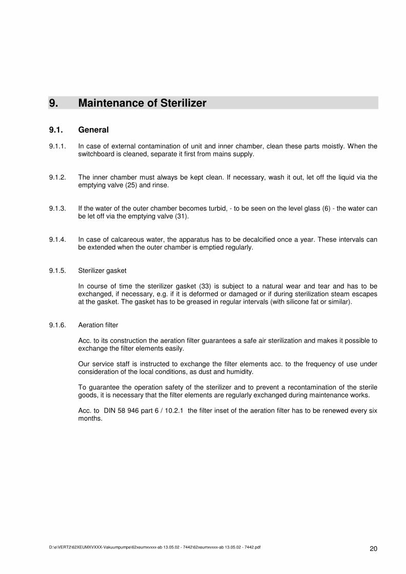
9. Maintenance of Sterilizer
9.1. General
9.1.1. In case of external contamination of unit and inner chamber, clean these parts moistly. When the switchboard is cleaned, separate it first from mains supply.
9.1.2. The inner chamber must always be kept clean. If necessary, wash it out, let off the liquid via the emptying valve (25) and rinse.
9.1.3. If the water of the outer chamber becomes turbid, - to be seen on the level glass (6) - the water can be let off via the emptying valve (31).
9.1.4. In case of calcareous water, the apparatus has to be decalcified once a year. These intervals can be extended when the outer chamber is emptied regularly.
9.1.5. Sterilizer gasket In course of time the sterilizer gasket (33) is subject to a natural wear and tear and has to be exchanged, if necessary, e.g. if it is deformed or damaged or if during sterilization steam escapes at the gasket. The gasket has to be greased in regular intervals (with silicone fat or similar).
9.1.6. Aeration filter Acc. to its construction the aeration filter guarantees a safe air sterilization and makes it possible to exchange the filter elements easily. Our service staff is instructed to exchange the filter elements acc. to the frequency of use under consideration of the local conditions, as dust and humidity. To guarantee the operation safety of the sterilizer and to prevent a recontamination of the sterile goods, it is necessary that the filter elements are regularly exchanged during maintenance works. Acc. to DIN 58 946 part 6 / 10.2.1 the filter inset of the aeration filter has to be renewed every six months.
D:\e\VERT2\62XEUMXVXXX-Vakuumpumpe\62xeumxvxxx-ab 13.05.02 - 7442\62xeumxvxxx-ab 13.05.02 - 7442.pdf 21
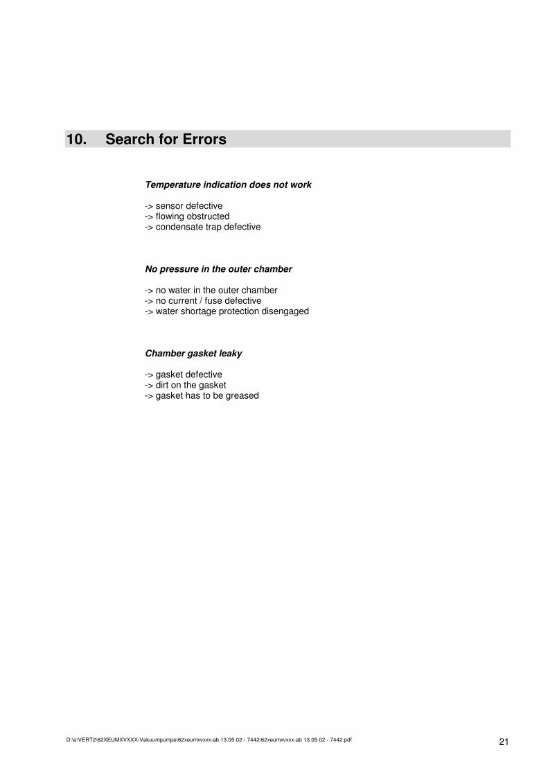
10. Search for Errors
Temperature indication does not work -> sensor defective -> flowing obstructed -> condensate trap defective
No pressure in the outer chamber -> no water in the outer chamber -> no current / fuse defective -> water shortage protection disengaged
Chamber gasket leaky -> gasket defective -> dirt on the gasket -> gasket has to be greased
D:\e\VERT2\62XEUMXVXXX-Vakuumpumpe\62xeumxvxxx-ab 13.05.02 - 7442\62xeumxvxxx-ab 13.05.02 - 7442.pdf 22
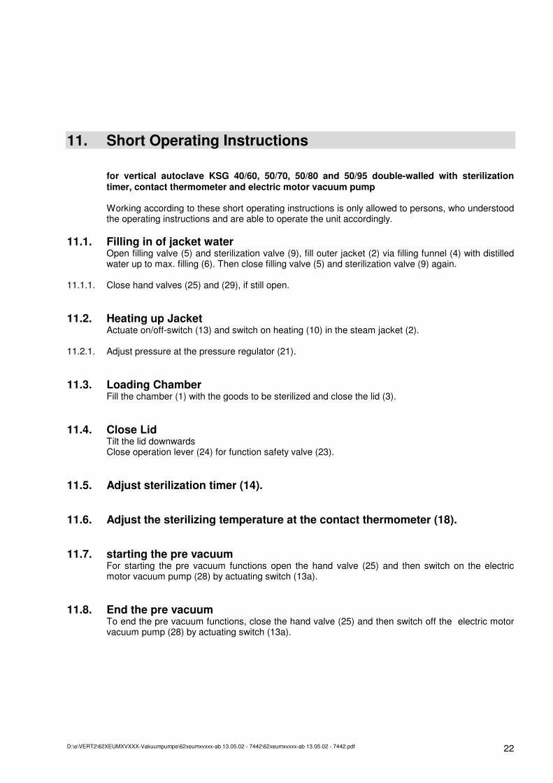
11. Short Operating Instructions for vertical autoclave KSG 40/60, 50/70, 50/80 and 50/95 double-walled with sterilization timer, contact thermometer and electric motor vacuum pump Working according to these short operating instructions is only allowed to persons, who understood the operating instructions and are able to operate the unit accordingly.
11.1. Filling in of jacket water Open filling valve (5) and sterilization valve (9), fill outer jacket (2) via filling funnel (4) with distilled water up to max. filling (6). Then close filling valve (5) and sterilization valve (9) again.
11.1.1. Close hand valves (25) and (29), if still open.
11.2. Heating up Jacket Actuate on/off-switch (13) and switch on heating (10) in the steam jacket (2).
11.2.1. Adjust pressure at the pressure regulator (21).
11.3. Loading Chamber Fill the chamber (1) with the goods to be sterilized and close the lid (3).
11.4. Close Lid Tilt the lid downwards Close operation lever (24) for function safety valve (23).
11.5. Adjust sterilization timer (14).
11.6. Adjust the sterilizing temperature at the contact thermometer (18).
11.7. starting the pre vacuum For starting the pre vacuum functions open the hand valve (25) and then switch on the electric motor vacuum pump (28) by actuating switch (13a).
11.8. End the pre vacuum To end the pre vacuum functions, close the hand valve (25) and then switch off the electric motor vacuum pump (28) by actuating switch (13a).
D:\e\VERT2\62XEUMXVXXX-Vakuumpumpe\62xeumxvxxx-ab 13.05.02 - 7442\62xeumxvxxx-ab 13.05.02 - 7442.pdf 23
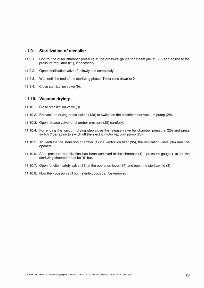
11.9. Sterilization of utensils:
11.9.1. Control the outer chamber pressure at the pressure gauge for steam jacket (20) and adjust at the pressure regulator (21), if necessary.
11.9.2. Open sterilization valve (9) slowly and completely.
11.9.3. Wait until the end of the sterilizing phase. Timer runs down to 0.
11.9.4. Close sterilization valve (9).
11.10. Vacuum drying:
11.10.1. Close sterilization valve (9).
11.10.2. For vacuum drying press switch (13a) to switch on the electric motor vacuum pump (28).
11.10.3. Open release valve for chamber pressure (25) carefully.
11.10.4. For ending the vacuum drying step close the release valve for chamber pressure (25) and press switch (13a) again to switch off the electric motor vacuum pump (28).
11.10.5. To ventilate the sterilizing chamber (1) via ventilation filter (35), the ventilation valve (34) must be opened.
11.10.6. After pressure equalization has been achieved in the chamber (1) - pressure gauge (19) for the sterilizing chamber must be "0" bar.
11.10.7. Open function safety valve (23) at the operation lever (24) and open the sterilizer lid (3).
11.10.8. Now the - possibly still hot - sterile goods can be removed.

D:\e\VERT2\62XEUMXVXXX-Vakuumpumpe\62xeumxvxxx-ab 13.05.02 - 7442\62xeumxvxxx-ab 13.05.02 - 7442.pdf 24
3 3a
4
30
23
24
21
10 10
11a
19 20
34
25
9
31 28
26 27
32
27a 18a
D:\e\VERT2\62XEUMXVXXX-Vakuumpumpe\62xeumxvxxx-ab 13.05.02 - 7442\62xeumxvxxx-ab 13.05.02 - 7442.pdf 25
34
35
19
21
20
9 11a
35a
18a
26 9
22
11
D:\e\VERT2\62XEUMXVXXX-Vakuumpumpe\62xeumxvxxx-ab 13.05.02 - 7442\62xeumxvxxx-ab 13.05.02 - 7442.pdf 26
8
7
6
8
8a
D:\e\VERT2\62XEUMXVXXX-Vakuumpumpe\62xeumxvxxx-ab 13.05.02 - 7442\62xeumxvxxx-ab 13.05.02 - 7442.pdf 27
5 21
4
5a
3
35
35a
34
12
8a
3a 3a
D:\e\VERT2\62XEUMXVXXX-Vakuumpumpe\62xeumxvxxx-ab 13.05.02 - 7442\62xeumxvxxx-ab 13.05.02 - 7442.pdf 28
12
13 13a
14
17
16 15
18
D:\e\VERT2\62XEUMXVXXX-Vakuumpumpe\62xeumxvxxx-ab 13.05.02 - 7442\62xeumxvxxx-ab 13.05.02 - 7442.pdf 29
29 29a 32a 32a
27a
27
28
18
1
2
33
D:\e\VERT2\62XEUMXVXXX-Vakuumpumpe\62xeumxvxxx-ab 13.05.02 - 7442\62xeumxvxxx-ab 13.05.02 - 7442.pdf 30
D:\e\VERT2\62XEUMXVXXX-Vakuumpumpe\62xeumxvxxx-ab 13.05.02 - 7442\62xeumxvxxx-ab 13.05.02 - 7442.pdf 31