627 BI Angular Position Sensors HELLA EN print€¦ · Angular Position Sensors Single and double...
6
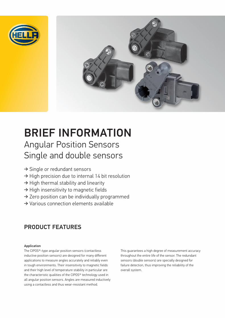
BRIEF INFORMATION Angular Position Sensors Single and double sensors ➔ Single or redundant sensors ➔ High precision due to internal 14 bit resolution ➔ High thermal stability and linearity ➔ High insensitivity to magnetic fields ➔ Zero position can be individually programmed ➔ Various connection elements available PRODUCT FEATURES Application The CIPOS®-type angular position sensors (contactless inductive position sensors) are designed for many different applications to measure angles accurately and reliably even in tough environments. Their insensitivity to magnetic fields and their high level of temperature stability in particular are the characteristic qualities of the CIPOS® technology used in all angular position sensors. Angles are measured inductively using a contactless and thus wear-resistant method. This guarantees a high degree of measurement accuracy throughout the entire life of the sensor. The redundant sensors (double sensors) are specially designed for failure detection, thus improving the reliability of the overall system.
Transcript of 627 BI Angular Position Sensors HELLA EN print€¦ · Angular Position Sensors Single and double...
BRIEF INFORMATIONAngular Position SensorsSingle and double sensors
➔ Single or redundant sensors ➔ High precision due to internal 14 bit resolution ➔ High thermal stability and linearity ➔ High insensitivity to magnetic fields ➔ Zero position can be individually programmed ➔ Various connection elements available
PRODUCT FEATURES
ApplicationThe CIPOS®-type angular position sensors (contactless inductive position sensors) are designed for many different applications to measure angles accurately and reliably even in tough environments. Their insensitivity to magnetic fields and their high level of temperature stability in particular are the characteristic qualities of the CIPOS® technology used in all angular position sensors. Angles are measured inductively using a contactless and thus wear-resistant method.
This guarantees a high degree of measurement accuracy throughout the entire life of the sensor. The redundant sensors (double sensors) are specially designed for failure detection, thus improving the reliability of the overall system.
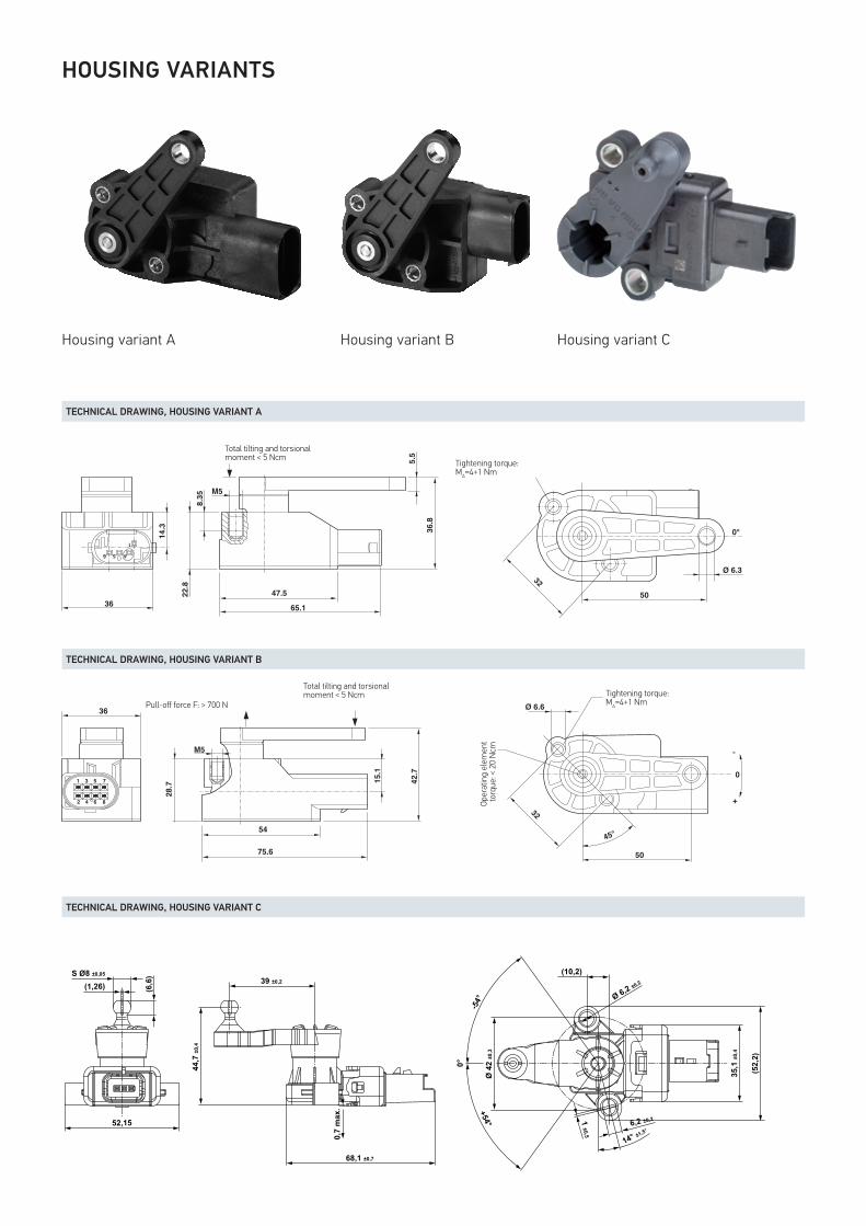
Housing variant A Housing variant CHousing variant B
TECHNICAL DRAWING, HOUSING VARIANT A
TECHNICAL DRAWING, HOUSING VARIANT B
TECHNICAL DRAWING, HOUSING VARIANT C
456
1
Ø 6.3
50
65.1
47.5
M5
32
36.8
22.8
8.35
14.3
5.5
36
0°
A
Kipp- und Torsionsmomentinsgesamt <5Ncm
Befestigungsdrehmoment:M =4+1Nm
456
1
Ø 6.3
50
65.1
47.5
M5
32
36.8
22.8
8.35
14.3
5.5
36
0°
A
Kipp- und Torsionsmomentinsgesamt <5Ncm
Befestigungsdrehmoment:M =4+1Nm
Total tilting and torsional moment < 5 Ncm
Tightening torque: MA=4+1 Nm
Abreisskraft F: > 700 N
M5
42.7
75.6
15.1
54
Kipp- und Torsionsmomentinsgesamt <5Ncm
28.77531
8642
36
50
Ø 6.6
32
45°
Befestigungsdrehmoment:M =4+1Nm
Drehmomentdes Bedienelements: < 20 Ncm
A
-
+
0
Total tilting and torsional moment < 5 Ncm
Pull-off force F: > 700 N
Abreisskraft F: > 700 N
M5
42.7
75.6
15.1
54
Kipp- und Torsionsmomentinsgesamt <5Ncm
28.77531
8642
36
50
Ø 6.6
32
45°
Befestigungsdrehmoment:M =4+1Nm
Drehmomentdes Bedienelements: < 20 Ncm
A
-
+
0
Tightening torque: MA=4+1 Nm
Oper
atin
g el
emen
t to
rque
: < 2
0 N
cm
39 ±0,2
68,1 ±0,7
0,7
max
.
44,7
±0,4
52,15
(6,6
)S Ø8 ±0,05
(1,26)
Ø 6,2 ±0,2
-54°
+54°
0°
Ø 4
2 ±0
,3
1 ±0,5
6,2 ±0,2
35,1
±0,4
(52,
2)
14° ±1,5°
(10,2)
39 ±0,2
68,1 ±0,7
0,7
max
.
44,7
±0,4
52,15
(6,6
)S Ø8 ±0,05
(1,26)
Ø 6,2 ±0,2
-54°
+54°
0°
Ø 4
2 ±0
,3
1 ±0,5
6,2 ±0,2
35,1
±0,4
(52,
2)
14° ±1,5°
(10,2)
HOUSING VARIANTS
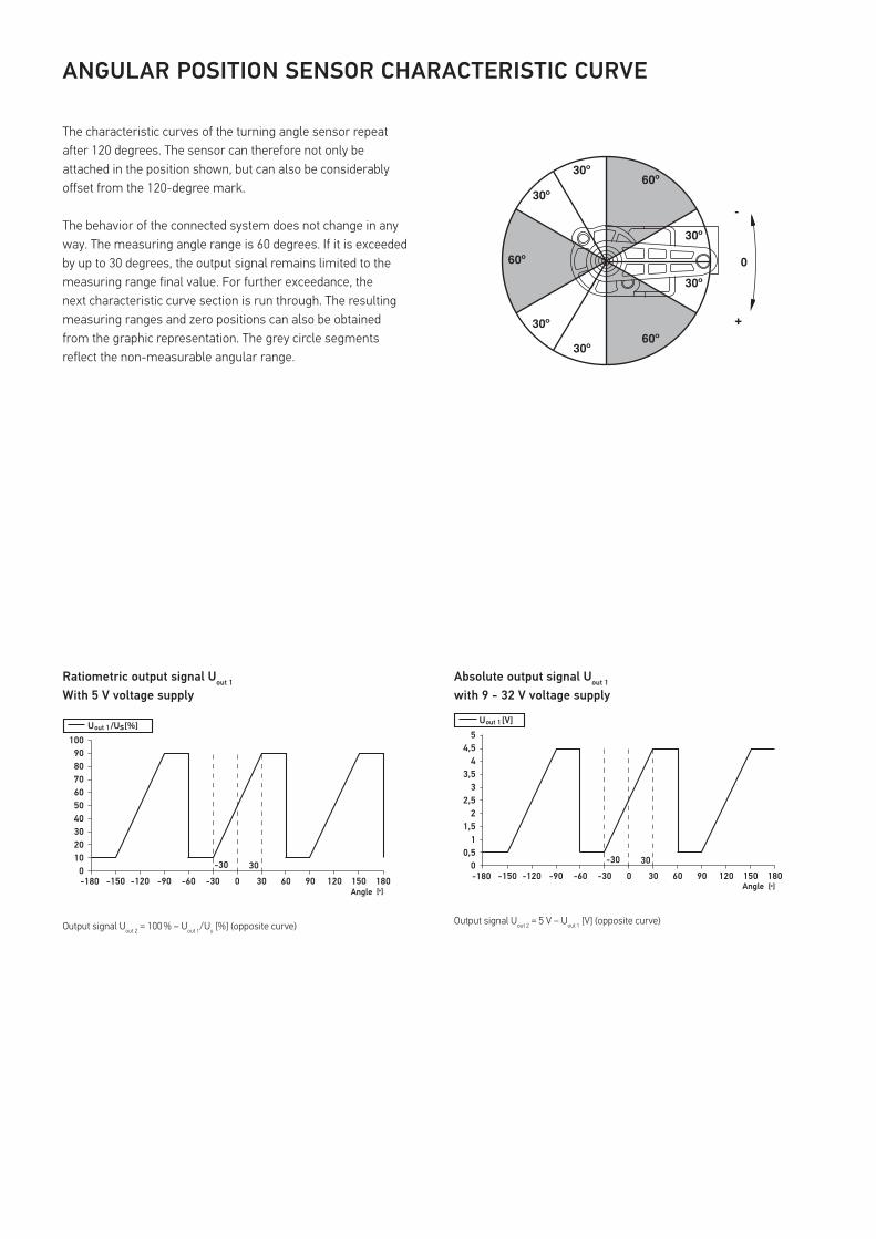
The characteristic curves of the turning angle sensor repeat after 120 degrees. The sensor can therefore not only be attached in the position shown, but can also be considerably offset from the 120-degree mark.
The behavior of the connected system does not change in any way. The measuring angle range is 60 degrees. If it is exceeded by up to 30 degrees, the output signal remains limited to the measuring range final value. For further exceedance, the next characteristic curve section is run through. The resulting measuring ranges and zero positions can also be obtained from the graphic representation. The grey circle segments reflect the non-measurable angular range.
ANGULAR POSITION SENSOR CHARACTERISTIC CURVE
Ratiometric output signal Uout 1
With 5 V voltage supplyAbsolute output signal Uout 1 with 9 - 32 V voltage supply
Output signal Uout 2 = 100 % – Uout 1/Us [%] (opposite curve) Output signal Uout 2 = 5 V – Uout 1 [V] (opposite curve)
-180 -150 -120 -90 -60 -30 0 30 60 90 120 150 180
1020
0
30405060708090
100
-30 30
Winkel [ ]̊
U /U [%] out 1 s
-180 -150 -120 -90 -60 -30 0 30 60 90 120 150 180
0,51
0
1,52
2,53
3,54
4,55
-30 30
U [V] out 1
Winkel [ ]̊Angle
60º
60º
60º
30º
30º
30º
30º
30º
30º
-
+
0
-180 -150 -120 -90 -60 -30 0 30 60 90 120 150 180
0,51
0
1,52
2,53
3,54
4,55
-30 30
U [V] out 1
Winkel [ ]̊Angle
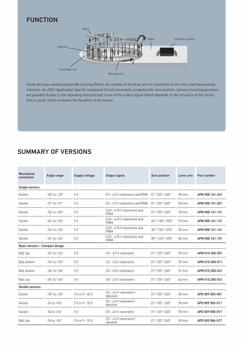
Inside the laser-welded polyamide housing (PA66), the rotation of the lever arm is transferred to the rotor and measured by induction. An ASIC (Application Specific Integrated Circuit) accurately computes the rotor position. Various mounting positions are possible thanks to the repeating characteristic curve of the output signal (which depends on the structure of the sensor that is used), which increases the flexibility of the sensor.
FUNCTION
SUMMARY OF VERSIONS
Rotor
Stator Elektronik
Induktion
Transmitter SpuleEmpfängerspuleReceiver coil
Transmitter coil
Induction
Rotor
Stator Electronic system
Mechanical connection Angle range Supply voltage Output signal Zero position Lever arm Part number
Single sensors
Socket - 30° to + 30° 5 V 0.5 - 4.5 V ratiometric and PWM 0° / 120° / 240° 50 mm 6PM 008 161-241
Socket - 51° to + 51° 5 V 0.5 - 4.5 V ratiometric and PWM 0° / 120° / 240° 50 mm 6PM 008 161-251
Socket - 54° to + 54° 5 V 0.25 - 4.75 V ratiometric and PWM 0° / 120° / 240° 70 mm 6PM 008 161-121
Socket - 54° to + 54° 5 V 0.25 - 4.75 V ratiometric and PWM 60° / 180° / 300° 70 mm 6PM 008 161-131
Socket - 54° to + 54° 5 V 0.25 - 4.75 V ratiometric and PWM 30° / 150° / 270° 50 mm 6PM 008 161-141
Socket - 54° to + 54° 5 V 0.25 - 4.75 V ratiometric and PWM 90° / 210° / 330° 50 mm 6PM 008 161-151
Basic sensors – Compact design
Ball, top - 54° to + 54° 5 V 0.5 - 4.5 V ratiometric 0° / 120° / 240° 39 mm 6PM 010 200-501
Ball, bottom - 54° to + 54° 5 V 0.5 - 4.5 V ratiometric 0° / 120° / 240° 39 mm 6PM 010 200-511
Ball, bottom - 54° to + 54° 5 V 0.5 - 4.5 V ratiometric 0° / 120° / 240° 51 mm 6PM 010 200-521
Ball, top - 54° to + 54° 5 V 0.5 - 4.5 V ratiometric 0° / 120° / 240° 64 mm 6PM 010 200-531
Double sensors
Socket - 30° to + 30° 5 V or 9 - 32 V 0.5 - 4.5 V ratiometric/ absolute 0° / 120° / 240° 50 mm 6PD 009 583-001
Socket - 54 to + 54° 5 V or 9 - 32 V 0.5 - 4.5 V ratiometric/ absolute 0° / 120° / 240° 50 mm 6PD 009 583-011
Socket - 54 to + 54° 5 V 0.5 - 4.5 V ratiometric 0° / 120° / 240° 70 mm 6PD 009 580-017
Ball, top - 54 to + 54° 5 V or 9 - 32 V 0.5 - 4.5 V ratiometric/ absolute 0° / 120° / 240° 90 mm 6PD 009 584-017
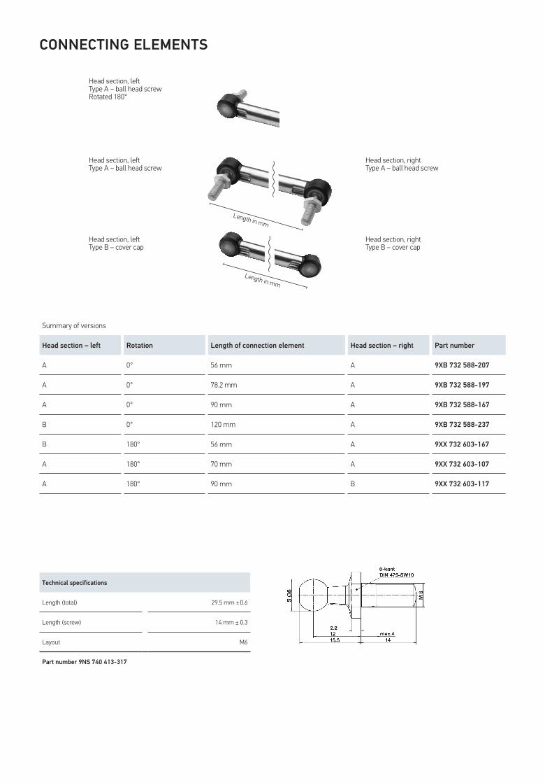
CONNECTING ELEMENTS
Technical specifications
Length (total) 29.5 mm ± 0.6
Length (screw) 14 mm ± 0.3
Layout M6
Part number 9NS 740 413-317
Summary of versions
Head section – left Rotation Length of connection element Head section – right Part number
A 0° 56 mm A 9XB 732 588-207
A 0° 78.2 mm A 9XB 732 588-197
A 0° 90 mm A 9XB 732 588-167
B 0° 120 mm A 9XB 732 588-237
B 180° 56 mm A 9XX 732 603-167
A 180° 70 mm A 9XX 732 603-107
A 180° 90 mm B 9XX 732 603-117
Head section, leftType A – ball head screw Rotated 180°
Head section, leftType A – ball head screw
Head section, rightType A – ball head screw
Head section, leftType B – cover cap
Head section, rightType B – cover cap
Length in mm
Length in mm

HELLA KGaA Hueck & Co.Rixbecker Straße 7559552 Lippstadt, GermanyTel.: +49 2941 38-0Fax: +49 2941 38-7133Internet: www.hella.com
© HELLA KGaA Hueck & Co., Lippstadt J00627/01.17 wSubject to technical and price modifications.