
62
74
TAC Notice: What's Changing on TAC Web Help us help you. Please rate this document. Excellent Good Average Fair Poor This document solved my problem. Yes No Just browsing Suggestions for improvement: (256 character limit) Understanding and Troubleshooting HSRP Problems in Catalyst Switch Networks Contents Introduction Prerequisites Requirements Components Used Conventions Understand HSRP Background Information Basic Operation HSRP Terms HSRP Addressing ICMP Redirects HSRP Functionality Matrix HSRP Features Packet Format HSRP States HSRP Timers HSRP Events HSRP Actions HSRP State Table Packet Flow Troubleshoot HSRP Case Studies Case Study #1: HSRP Standby IP Address Is Reported as a Duplicate IP Address Case Study #2: HSRP State Continuously Changes (Active, Standby, Speak) or %HSRP-6-STATECHANGE Case Study #3: HSRP Does Not Recognize Peer Case Study #4: HSRP State Changes and Switch Reports SYS-4-P2_WARN: 1/Host <mac_address> Is Flapping Between Port <port_1> and Port <port_2> in Syslog Case Study #5: HSRP State Changes and Switch Reports RTD-1-ADDR_FLAP in Syslog Case Study #6: HSRP State Changes and Switch Reports MLS-4-MOVEOVERFLOW:Too many moves, stop MLS for 5 sec(20000000) in Syslog
-
Upload
cedric-mignon -
Category
Documents
-
view
72 -
download
8
Transcript of 62

TAC Notice Whats Changing on TAC Web
Help us help you
Please rate this document
Excellent
Good
Average
Fair
Poor
This document solved my problem
Yes
No
Just browsing
Suggestions for improvement
(256 character limit)
Understanding and Troubleshooting HSRP Problems in Catalyst Switch Networks
Contents
Introduction Prerequisites Requirements Components Used Conventions Understand HSRP Background Information Basic Operation HSRP Terms HSRP Addressing ICMP Redirects HSRP Functionality Matrix HSRP Features Packet Format HSRP States HSRP Timers HSRP Events HSRP Actions HSRP State Table Packet Flow Troubleshoot HSRP Case Studies Case Study 1 HSRP Standby IP Address Is Reported as a Duplicate IP Address Case Study 2 HSRP State Continuously Changes (Active Standby Speak) or HSRP-6-STATECHANGE Case Study 3 HSRP Does Not Recognize Peer Case Study 4 HSRP State Changes and Switch Reports SYS-4-P2_WARN 1Host ltmac_addressgt Is Flapping Between Port ltport_1gt and Port ltport_2gt in Syslog Case Study 5 HSRP State Changes and Switch Reports RTD-1-ADDR_FLAP in Syslog Case Study 6 HSRP State Changes and Switch Reports MLS-4-MOVEOVERFLOWToo many moves stop MLS for 5 sec(20000000) in Syslog
Case Study 7 HSRP Intermittent State Changes on Multicast Stub Network Case Study 8 Asymmetric Routing and HSRP (Excessive Flooding of Unicast Traffic in Network with Routers That Run HSRP) Case Study 9 HSRP Virtual IP Address Is Reported as a Different IP Address Case Study 10 HSRP Causes MAC Violation on a Secure Port Case Study 11 Interface Hardware Cannot Support Multiple Groups HSRP Troubleshooting Modules for CatOS Switches A Verify HSRP Router Configuration B Verify Catalyst Fast EtherChannel and Trunking Configuration C Verify Physical Layer Connectivity D Layer 3 HSRP Debugging E Spanning Tree Troubleshooting F CGMP Leave Processing and HSRP Interoperability G Divide and Conquer H High CPU with Asymmetric Traffic in HSRP Known Issues Number of HSRP Groups Supported for Catalyst 65006000 Series PFC2MSFC2 and Catalyst 3550 HSRP State FlappingUnstable When You Use Cisco 26202621 Cisco 3600 with Fast Ethernet or PA-2FEISL HSRP Stuck in Initial or Active State on Cisco 26202621 Cisco 3600 with Fast Ethernet or PA-2FEISL Unable to Ping HSRP Standby Address on Cisco 2500 and 4500 Series Routers MLS Flows Are Not Created for Devices That Use HSRP Standby IP Address as Default Gateway Catalyst 2948G 2980G 4912G 4003 and 4006 HSRP-CGMP Interoperability Issues Cisco Support Community - Featured Conversations Related Information
Introduction
Because of the nature of the Hot Standby Router Protocol (HSRP) specific network problems can lead to HSRP instability This document covers common issues and ways to troubleshoot HSRP problems Most HSRP-related problems are not true HSRP issues Instead they are network problems that affect the behavior of HSRP
This document covers these most-common issues that relate to HSRP
Router report of a duplicate HSRP standby IP address
Constant HSRP state changes (active standby speak)
Missing HSRP peers
Switch error messages that relate to HSRP
Excessive network unicast flooding to the HSRP configuration
Note This document details how to troubleshoot HSRP in Catalyst switch environments The document contains many references to software versions and network topology design Nevertheless the sole purpose of this document is to facilitate and guide engineers on who to troubleshoot HSRP This document is not intended to be a design guide software-recommendation document or a best practices document
Prerequisites
Requirements
There are no specific requirements for this document
Components Used
This document is not restricted to specific software and hardware versions
The information in this document was created from the devices in a specific lab environment All of the devices used in this document started with a cleared (default) configuration If your network is live make sure that you understand the potential impact of any command
Conventions
Refer to Cisco Technical Tips Conventions for more information on document conventions
Understand HSRP
Background Information
Businesses and consumers that rely on intranet and Internet services for their mission-critical communications require and expect their networks and applications to be continuously available to them Customers can satisfy their demands for near-100 percent network uptime if they leverage the HSRP in Cisco IOSreg Software HSRP which is unique to Cisco platforms provides network redundancy for IP networks in a manner that ensures that user traffic immediately and transparently recovers from first-hop failures in network edge devices or access circuits
Two or more routers can act as a single virtual router if they share an IP address and a MAC (Layer 2 [L2]) address The address is necessary for host workstation default gateway redundancy Most host workstations do not contain routing tables and use only a single next hop IP and MAC address This address is known as a default gateway With HSRP members of the virtual router group continually exchange status messages One router can assume the routing responsibility of another if a router goes out of commission for either planned or unplanned
reasons Hosts are configured with a single default gateway and continue to forward IP packets to a consistent IP and MAC address The changeover of devices that do the routing is transparent to the end workstations
Note You can configure host workstations that run Microsoft OS for multiple default gateways But the multiple default gateways are not dynamic The OS only uses one single default gateway at a time The system only selects an additional configured default gateway at boot time if the first configured default gateway is determined unreachable by Internet Control Management Protocol (ICMP)
Basic Operation
A set of routers that run HSRP works in concert to present the illusion of a single default gateway router to the hosts on the LAN This set of routers is known as an HSRP group or standby group A single router that is elected from the group is responsible for the forwarding of the packets that hosts send to the virtual router This router is known as the active router Another router is elected as the standby router If the active router fails the standby assumes the packet forwarding duties Although an arbitrary number of routers may run HSRP only the active router forwards the packets that are sent to the virtual router IP address
In order to minimize network traffic only the active and the standby routers send periodic HSRP messages after the protocol has completed the election process Additional routers in the HSRP group remain in the Listen state If the active router fails the standby router takes over as the active router If the standby router fails or becomes the active router another router is elected as the standby router
Each standby group emulates a single virtual router (default gateway) For each group a single well-known MAC and IP address is allocated to that group Multiple standby groups can coexist and overlap on a LAN and individual routers can participate in multiple groups In this case the router maintains a separate state and timers for each group
HSRP Terms
Term Definition
Active routerThe router that currently forwards packets for the virtual router
Standby router The primary backup router
Standby groupThe set of routers that participate in HSRP and jointly emulate a virtual router
Hello timeThe interval between successive HSRP hello messages from a given router
Hold timeThe interval between the receipt of a hello message and the presumption that the sending router has failed
HSRP Addressing
HSRP Router Communication
Routers that run HSRP communicate HSRP information between each other through HSRP hello packets These packets are sent to the destination IP multicast address 224002 on User Datagram Protocol (UDP) port 1985 IP multicast address 224002 is a reserved multicast address that is used to communicate to all routers The active router sources hello packets from its configured IP address and the HSRP virtual MAC address The standby router sources hellos from its configured IP address and the burned-in MAC address (BIA) This use of source addressing is necessary so that HSRP routers can correctly identify each other
In most cases when you configure routers to be part of an HSRP group the routers listen for the HSRP MAC address for that group as well as their own BIA The only exception to this behavior is for Cisco 2500 4000 and 4500 routers These routers have Ethernet hardware that only recognizes a single MAC address Therefore these routers use the HSRP MAC address when they serve as the active router The routers use their BIA when they serve as the standby router
HSRP Standby IP Address Communication on All Media Except Token Ring
Because host workstations are configured with their default gateway as the HSRP standby IP address hosts must communicate with the MAC address that is associated with the HSRP standby IP address This MAC address is a virtual MAC address that is composed of 00000c07ac The is the HSRP group number in hexadecimal based on the respective interface For example HSRP group 1 uses the HSRP virtual MAC address of 00000c07ac01 Hosts on the adjoining LAN segment use the normal Address Resolution Protocol (ARP) process in order to resolve the associated MAC addresses
HSRP Standby IP Address Communication on Token Ring Media
Token Ring interfaces use functional addresses for the HSRP MAC address Functional addresses are the only general multicast mechanism available There is a limited number of Token Ring functional addresses available and many of these addresses are reserved for other functions These three addresses are the only addresses available for use with HSRP
c00000010000 (group 0)c00000020000 (group 1)c00000040000 (group 2)
Therefore you can configure only three HSRP groups on Token Ring interfaces unless you configure the standby use-bia parameter
ICMP Redirects
HSRP peer routers that protect a subnet are able to provide access to all other subnets in the network This is the basis of HSRP Therefore which router becomes the active HSRP router is irrelevant In Cisco IOS software releases earlier than Cisco IOS Software Release 121(3)T ICMP redirects are automatically disabled on an interface when HSRP is used on that interface Without this configuration the hosts can be redirected away from the HSRP virtual IP address and toward an interface IP and MAC address of a single router Redundancy is lost
Cisco IOS Software Release 121(3)T introduces a method to allow ICMP redirects with HSRP This method filters outbound ICMP redirect messages through HSRP The next hop IP address is changed to an HSRP virtual address The gateway IP address in the outbound ICMP redirect message is compared to a list of HSRP active routers that are present on that network If the router that corresponds to the gateway IP address is an active router for an HSRP group the gateway IP address is replaced with that group virtual IP address This solution allows hosts to learn optimal routes to remote networks and at the same time maintain the resilience that HSRP provides
HSRP Functionality Matrix
Refer to the Cisco IOS Release and HSRP Functionality Matrix section of Hot Standby Router Protocol Features and Functionality in order to learn about the features and Cisco IOS Software releases that support HSRP
HSRP Features
Refer to Hot Standby Router Protocol Features and Functionality for information on most of the HSRP features This document provides information on these HSRP features
Preemption
Interface tracking
Use of a BIA
Multiple HSRP groups
Configurable MAC addresses
Syslog support
HSRP debugging
Enhanced HSRP debugging
Authentication
IP redundancy
Simple Network Management Protocol (SNMP) MIB
HSRP for Multiprotocol Label Switching (MPLS)
Note You can use your browser Find feature in order to locate these sections within the document
Packet Format
This table shows the format of the data portion of the UDP HSRP frame
Version Op Code State Hellotime
Holdtime Priority Group Reserved
Authentication Data
Authentication Data
Virtual IP Address
This table describes each of the fields in the HSRP packet
Packet Field Description
Op Code (1 octet)
The Op Code describes the type of message that the packet contains Possible values are 0 - hello 1 - coup and 2 - resign Hello messages are sent to indicate that a router runs HSRP and is able to become the active router Coup messages are sent when a router wishes to become the active router Resign messages are sent when a router no longer wishes to be the active router
State (1 octet)
Each router in the standby group implements a state machine The state field describes the current state of the router that sends the message These are details on the individual states 0 - initial 1 - learn 2 - listen 4 - speak 8 - standby and 16 - active
Hellotime (1 octet)
This field is only meaningful in hello messages It contains the approximate period between the hello messages that the router sends The time is given in seconds
Holdtime (1 octet)
This field is only meaningful in hello messages It contains the amount of time that the routers wait for a hello message before they initiate a state change
Priority (1 octet)
This field is used to elect the active and standby routers In a comparison of the priorities of two routers the router with the highest value becomes the active router The tie breaker is the router with the higher IP address
Group (1 octet)This field identifies the standby group
Authentication Data (8 octets)This field contains a cleartext eight-character password
Virtual IP Address (4 octets)
If the virtual IP address is not configured on a router the address can be learned from the hello message from the active router An address is only learned if no HSRP standby IP address has been configured and the hello message is authenticated (if authentication is configured)
HSRP States
State Definition
Initial
This is the state at the start This state indicates that HSRP does not run This state is entered through a configuration change or when an interface first becomes available
Learn
The router has not determined the virtual IP address and has not yet seen an authenticated hello message from the active router In this state the router still waits to hear from the active router
Listen The router knows the virtual IP address but the router is neither the active router nor the standby router It listens for hello messages from those routers
Speak
The router sends periodic hello messages and actively participates in the election of the active andor standby router A router cannot enter speak state unless the router has the virtual IP address
Standby
The router is a candidate to become the next active router and sends periodic hello messages With the exclusion of transient conditions there is at most one router in the group in standby state
Active
The router currently forwards packets that are sent to the group virtual MAC address The router sends periodic hello messages With the exclusion of transient conditions there must be at most one router in active state in the group
HSRP Timers
Each router only uses three timers in HSRP The timers time hello messages The HSRP converges when a failure occurs depend on how the HSRP hello and hold timers are configured By default these timers are set to 3 and 10 seconds respectively which means that a hello packet is sent between the HSRP standby group devices every 3 seconds and the standby device becomes active when a hello packet has not been received for 10 seconds You can lower these timer settings to speed up the failover or preemption but to avoid increased CPU usage and unnecessary standby state flapping do not set the hello timer below one (1) second or the hold timer below 4 seconds Note that if you use the HSRP tracking mechanism and the tracked link fails the failover or preemption occurs immediately regardless of the hello and hold timers When a timer expires the router transitions to a new HSRP state The timers can be changed with this command standby [group-number] timers hellotime holdtime For example standby 1 timers 5 15
This table provides more information on these timers
Timer Description
Active timer
This timer is used to monitor the active router This timer starts any time an active router receives a hello packet This timer expires in accordance with the hold time value that is set in the related field of the HSRP hello message
Standby timer
This timer is used in order to monitor the standby router The timer starts any time the standby router receives a hello packet This timer expires in accordance with the hold time value that is set in the respective hello packet
Hello timerThis timer is used to clock hello packets All HSRP routers in any HSRP state generate a hello packet when this hello timer expires
HSRP Events
This table provides the events in the HSRP finite state machine
Key Events
1 HSRP is configured on an enabled interface
2 HSRP is disabled on an interface or the interface is disabled
3
Active timer expiry
The active timer is set to the hold time when the last hello message is seen from the active router
4
Standby timer expiry
The standby timer is set to the hold time when the last hello message is seen from the standby router
5Hello timer expiry
The periodic timer for the send of hello messages is expired
6Receipt of a hello message of higher priority from a router in speak state
7Receipt of a hello message of higher priority from the active router
8Receipt of a hello message of lower priority from the active router
9 Receipt of a resign message from the active router
10 Receipt of a coup message from a higher priority router
11Receipt of a hello message of higher priority from the standby router
12Receipt of a hello message of lower priority from the standby router
HSRP Actions
This table specifies the actions to be taken as part of the state machine
Initial Action
A
Start active timermdashIf this action occurrs as the result of the receipt of an authenticated hello message from the active router the active timer is set to the hold time field in the hello message Otherwise the active timer is set to the current hold time value that is in use by this router The active timer then starts
B
Start standby timermdashIf this action occurrs as the result of the receipt of an authenticated hello message from the standby router the standby timer is set to the hold time field in the hello message Otherwise the standby timer is set to the current hold time value that is in use by this router The standby timer then starts
C Stop active timermdashThe active timer stops
D Stop standby timermdashThe standby timer stops
E
Learn parametersmdashThis action is taken when an authenticated message is received from the active router If the virtual IP address for this group is not manually configured the virtual IP address can be learned from the message The router can learn hello time and hold time values from the message
FSend hello messagemdashThe router sends a hello message with its current state hello time and hold time
GSend coup messagemdashThe router sends a coup message in order to inform the active router that there is a higher-priority router available
HSend resign messagemdashThe router sends a resign message in order to allow another router to become the active router
I
Send gratuitous ARP messagemdashThe router broadcasts an ARP response packet that advertises the group virtual IP and MAC addresses The packet is sent with the virtual MAC address as the source MAC address in the link layer header as well as within the ARP packet
HSRP State Table
The diagram in this section shows the state transitions of the HSRP state machine Each time that an event occurs the associated action results and the router transitions to the next HSRP state In the diagram numbers designate
events and letters designate the associated action The table in the section HSRP Events defines the numbers and the table in the section HSRP Actions defines the letters Use this diagram only as a reference The diagram is detailed and is not necessary for general troubleshooting purposes
Packet Flow
Device MAC Address IP Address Subnet MaskDefault Gateway
PC1 00000c000001 101110 2552552550 10111
PC2 00000c001110 101210 2552552550 10121
Router A Configuration (Active Router)
interface ethernet 0 ip address 10112 2552552550 mac-address 400000000010 standby 1 ip 10111 standby 1 priority 200interface ethernet 1 ip address 10122 2552552550 mac-address 400000000011 standby 1 ip 10121 standby 1 priority 200
Router B Configuration (Standby Router)
interface ethernet 0 ip address 10113 2552552250 mac-address 400000000020 standby 1 ip 10111interface ethernet 1 ip address 10123 2552552550 mac-address 400000000021 standby 1 ip 10121
Note These examples configure static MAC addresses for illustration purposes only Do not configure static MAC addresses unless you are required to do so
You must understand the concept behind packet flow when you obtain sniffer traces in order to troubleshoot HSRP problems Router A uses the priority of 200 and becomes the active router on both interfaces In the example in this section packets from the router that are destined for a host workstation have the source MAC address of the router physical MAC address (BIA) Packets from the host machines that are destined for the HSRP IP address have the destination MAC address of the HSRP virtual MAC address Note that the MAC addresses are not the same for each flow between the router and the host
This table shows the respective MAC and IP address information per flow on the basis of a sniffer trace that is taken from Switch X
Packet Flow
Source MACDestination
MACSource
IPDestination
IP
Packets from PC1 that are destined for PC2
PC1 (00000c000001)
HSRP virtual MAC address of Router A interface Ethernet 0 (00000c07ac01)
101110 101210
Packets that return through Router A from PC2 and are destined for PC1
Router A Ethernet 0 BIA (400000000010)
PC1 (00000c000001)
101210 101110
Packets from PC1 that are destined for HSRP standby IP address (ICMP Telnet)
PC1 (00000c000001)
HSRP virtual MAC address of Router A interface Ethernet 0 (00000c07ac01)
101110 10111
Packets that are destined for the actual IP address of the active router (ICMP Telnet)
PC1 (00000c000001)
Router A Ethernet 0 BIA (400000000010)
101110 10112
Packets that are destined for the actual IP address of the standby router (ICMP Telnet)
PC1 (00000c000001)
Router B Ethernet 0 BIA (400000000020)
101110 10113
Troubleshoot HSRP Case Studies
Case Study 1 HSRP Standby IP Address Is Reported as a Duplicate IP Address
These error messages can appear
Oct 12 131541 STANDBY-3-DUPADDR Duplicate address 102501 on Vlan25 sourced by 00000c07ac19 Oct 13 162541 STANDBY-3-DUPADDR Duplicate address 102501 on Vlan25 sourced by 00000c07ac19 Oct 15 223102 STANDBY-3-DUPADDR Duplicate address 102501 on Vlan25 sourced by 00000c07ac19 Oct 15 224101 STANDBY-3-DUPADDR Duplicate address 102501 on Vlan25 sourced by 00000c07ac19
These error messages do not necessarily indicate an HSRP problem Rather the error messages indicate a possible Spanning Tree Protocol (STP) loop or routerswitch configuration issue The error messages are just symptoms of another problem
In addition these error messages do not prevent the proper operation of HSRP The duplicate HSRP packet is
ignored These error messages are throttled at 30-second intervals But slow network performance and packet loss can result from the network instability that causes the STANDBY-3-DUPADDR error messages of the HSRP address
These error messages can appear
Oct 15 224101 STANDBY-3-DUPADDR Duplicate address 102501 on Vlan25 sourced by 00000c07ac19
These messages specifically indicate that the router received a data packet that was sourced from the HSRP IP address on VLAN 25 with the MAC addresses 00000c07ac19 Since the HSRP MAC address is 00000c07ac19 either the router in question received its own packet back or both routers in the HSRP group went into the active state Because the router received its own packet the problem most likely is with the network rather than the router A variety of problems can cause this behavior Among the possible network problems that cause the error messages are
Momentary STP loops
EtherChannel configuration issues
Duplicated frames
When you troubleshoot these error messages see the troubleshooting steps in the HSRP Troubleshooting Modules for CatOS Switches section of this document All the troubleshooting modules are applicable to this section which includes modules on configuration In addition note any errors in the switch log and reference additional case studies as necessary
You can use an access list in order to prevent the active router from receiving its own multicast hello packet But this is only a workaround for the error messages and actually hides the symptom of the problem The workaround is to apply an extended inbound access list to the HSRP interfaces The access list blocks all traffic that is sourced from the physical IP address and that is destined to all routers multicast address 224002
access-list 101 deny ip host 17216123 host 224002 access-list 101 permit ip any any interface ethernet 0 ip address 17216123 2552552550 standby 1 ip 17216121 ip access-group 101 in
Case Study 2 HSRP State Continuously Changes (Active Standby Speak) or HSRP-6-STATECHANGE
These error messages can appear
Jan 9 080042623 STANDBY-6-STATECHANGE Standby 49
Vlan149 state Standby -gt ActiveJan 9 080056011 STANDBY-6-STATECHANGE Standby 49 Vlan149 state Active -gt SpeakJan 9 080103011 STANDBY-6-STATECHANGE Standby 49 Vlan149 state Speak -gt StandbyJan 9 080129427 STANDBY-6-STATECHANGE Standby 49 Vlan149 state Standby -gt ActiveJan 9 080136808 STANDBY-6-STATECHANGE Standby 49 Vlan149 state Active -gt SpeakJan 9 080143808 STANDBY-6-STATECHANGE Standby 49 Vlan149 state Speak -gt Standby
These error messages describe a situation in which a standby HSRP router did not receive three successive HSRP hello packets from its HSRP peer The output shows that the standby router moves from the standby state to the active state Shortly thereafter the router returns to the standby state Unless this error message occurs during the initial installation an HSRP issue probably does not cause the error message The error messages signify the loss of HSRP hellos between the peers When you troubleshoot this issue you must verify the communication between the HSRP peers A random momentary loss of data communication between the peers is the most common problem that results in these messages HSRP state changes are often due to High CPU Utilization If the error message is due to high CPU utilization put a sniffer on the network and the trace the system that causes the high CPU utilization
There are several possible causes for the loss of HSRP packets between the peers The most common problems are physical layer problems excessive network traffic caused by spanning tree issues or excessive traffic caused by each Vlan As with Case Study 1 all the troubleshooting modules are applicable to the resolution of HSRP state changes particularly the Layer 3 HSRP Debugging
If the loss of HSRP packets between peers is due to excessive traffic caused by each VLAN as mentioned you can tune or increase the SPD and hold the queue size to overcome the input queue drop problem
In order to increase the Selective Packet Discard (SPD) size go to the configuration mode and execute these commands on the Cat6500 switches
(config) ip spd queue max-threshold 600
--- Hidden Command
(config) ip spd queue min-threshold 500
--- Hidden Command
Note Refer to Understanding Selective Packet Discard (SPD) for more information on the SPD
In order to increase the hold queue size go to the VLAN interface mode and execute this command
(config-if) hold-queue 500 in
After you increase the SPD and hold queue size you can clear the interface counters if you execute the clear counter interfacecommand
Case Study 3 HSRP Does Not Recognize Peer
The router output in this section shows a router that is configured for HSRP but does not recognize its HSRP peers In order for this to occur the router must fail to receive HSRP hellos from the neighbor router When you troubleshoot this issue see the Verify Physical Layer Connectivity section and the Verify HSRP Router Configuration section of this document If the physical layer connectivity is correct check for the mismatched VTP modes
Vlan8 - Group 8Local state is Active priority 110 may preemptHellotime 3 holdtime 10Next hello sent in 000001168Hot standby IP address is 10122 configuredActive router is localStandby router is unknown expiredStandby virtual mac address is 00000c07ac085 state changes last state change 000503
Case Study 4 HSRP State Changes and Switch Reports SYS-4-P2_WARN 1Host ltmac_addressgt Is Flapping Between Port ltport_1gt and Port ltport_2gt in Syslog
These error messages can appear
2001 Jan 03 141843 SYS-4-P2_WARN 1Host 00000c149d08 is flapping between port 24 and port 23
In software version 552 and later for the Catalyst 45004000 and 2948G the switch reports a host MAC address that moves if the host MAC address moves twice within 15 seconds A common cause is an STP loop The switch discards packets from this host for about 15 seconds in an effort to minimize the impact of an STP loop If the MAC address move between two ports that is reported is the HSRP virtual MAC address the problem is most likely an issue in which both HSRP routers go into the active state
If the MAC address that is reported is not the HSRP virtual MAC address the issue can indicate the loop duplication or reflection of packets in the network These types of conditions can contribute to HSRP problems The most common causes for the move of MAC addresses are spanning tree problems or physical layer problems
When you troubleshoot this error message complete these steps
Note Also complete the steps in the HSRP Troubleshooting Modules for CatOS Switches section of this document
1 Determine the correct source (port) of the MAC address that the error message reports
2 Disconnect the port that must not source the host MAC address and check for HSRP stability
3 Document the STP topology on each VLAN and check for STP failure
4 Verify the port channel configuration
An incorrect port channel configuration can result in the flap of error messages by the host MAC address This is because of the load-balancing nature of port channeling
Case Study 5 HSRP State Changes and Switch Reports RTD-1-ADDR_FLAP in Syslog
These error messages can appear
Mar 9 145112 RTD-1-ADDR_FLAP Fast Ethernet 07 relearning 21 addrs per min Mar 9 145212 RTD-1-ADDR_FLAP Fast Ethernet 07 relearning 22 addrs per min Mar 9 145312 RTD-1-ADDR_FLAP Fast Ethernet 07 relearning 20 addrs per min Mar 9 145412 RTD-1-ADDR_FLAP Fast Ethernet 07 relearning 20 addrs per min Mar 9 145512 RTD-1-ADDR_FLAP Fast Ethernet 07 relearning 21 addrs per min Mar 9 145612 RTD-1-ADDR_FLAP Fast Ethernet 07 relearning 22 addrs per min Mar 9 145712 RTD-1-ADDR_FLAP Fast Ethernet 07 relearning 21 addrs per min
These error message signify that a MAC address moves consistently between different ports These error messages are only applicable on the Catalyst 2900XL and 3500XL switches The messages can indicate that two or more HSRP routers have become active The messages can indicate the source of an STP loop duplicated frames or reflected packets
In order to gather more information about the error messages issue this debug command
switchdebug ethernet-controller address
Ethernet Controller Addresses debugging is on l
Mar 9 080606 Add address 00000c07ac02 on port 35 vlan 2 Mar 9 080606 00000c07ac02 has moved from port 6 to port 35 in vlan 2 Mar 9 080607 Add address 00000c07ac02 on port 6 vlan 2
Mar 9 080607 00000c07ac02 has moved from port 35 to port 6 in vlan 2 Mar 9 080608 Add address 00000c07ac02 on port 35 vlan 2 Mar 9 080608 00000c07ac02 has moved from port 6 to port 35 in vlan 2 Mar 9 080610 Add address 00000c07ac02 on port 6 vlan 2 Mar 9 080610 00000c07ac02 has moved from port 35 to port 6 in vlan 2 Mar 9 080611 Add address 00000c07ac02 on port 35 vlan 2 Mar 9 080611 00000c07ac02 has moved from port 6 to port 35 in vlan 2 Mar 9 080612 RTD-1-ADDR_FLAP Fast Ethernet 07 relearning 20 addrs per min Mar 9 080613 Add address 00000c07ac02 on port 6 vlan 2 Mar 9 080613 00000c07ac02 has moved from port 35 to port 6 in vlan 2
The ports that the debug command references are off by one For example port 0 is Fast Ethernet 01 The error messages indicate the flap of a MAC address between ports 5 and 34 on the respective switch
Note The message RTD-1-ADDR_FLAP can be incorrect Refer to these Cisco bug IDs in order to rule out this possibility
CSCdp81680 ( registered customers only) mdashIncorrect RTD-1-ADDR_FLAP message
CSCds27100 ( registered customers only) and CSCdr30113 ( registered customers only) mdashFast EtherChannel issues cause RTD-1-ADDR_FLAP
The most common causes for the move of MAC addresses are spanning tree problems or physical layer problems
When you troubleshoot this error message complete these steps
Note Also complete the steps in the HSRP Troubleshooting Modules for CatOS Switches section of this document
1 Determine the correct source (port) of the host MAC address
2 Disconnect the port that should not source the host MAC address
3 Document the STP topology on a per-VLAN basis and check for STP failure
4 Verify the port channeling configuration
An incorrect port channel configuration can result in the flap of error messages by the host MAC address This is because of the load-balancing nature of port channeling
Case Study 6 HSRP State Changes and Switch Reports MLS-4-MOVEOVERFLOWToo many moves stop MLS for 5 sec(20000000) in Syslog
These error messages can appear
05132000085510MLS-4-MOVEOVERFLOWToo many moves stop MLS for 5 sec(20000000) 05132000085515MLS-4Resume MLS after detecting too many moves
These messages indicate that the switch learns the same MAC address on two different ports This message is only reported on Catalyst 55005000 switches Issue these commands in order to gather additional information about the problem
Note The commands that this section mentions are not documented You must enter them completely The show mls notification command provides a table address (TA) value The show looktable TA-value command returns a possible MAC address that you can trace to the root of the problem
Switch (enable) show mls notification
1 (0004e8e6-000202ce) Noti Chg TA e8e6 OI 2ce (1215) V 1
--- This is the modport and VLAN The MAC address is --- seen on this module 12 port 15 in VLAN 1
2 (0004e8e6-000202cd) Noti Chg TA e8e6 OI 2cd (1214) V 1
--- This is the modport and VLAN The next is seen on --- module 12 port 14 in VLAN 1
Write down the four-digitletter combination that appears after Chg TA in this command output The show looktable command gives the MAC address that causes the MLS TOO MANY MOVES error message
150S_CR(S2)gt (enable) show looktable e8e6
Table address 0xe8e6 Hash 0x1d1c Page 6 Entry Data[3-0] 0x000002cd 0x00800108 0x0008c790 0x215d0005 Entry Map [00]
Router-Xtag QOS SwGrp3 Port-Index 0 0 0x0 0x2cd
Fab AgeByte C-Mask L-Mask Static SwSc HwSc EnSc AL Trap R-Mac 0 0x01 0x0000 0x0000 0 0 0 0 0 0 0
MacAge Pri-In Modify Notify IPX-Sw IPX-Hw IPX-En Valid SwGrp2 Parity2
0 0 1 0 0 0 0 1 0x0 0
Entry-Mac-Address FID SwGrp1 Parity1 00-08-c7-90-21-5d 1 0x0 1
The entry MAC address 00-08-c7-90-21-5d is the MAC address that flaps between ports You must know the MAC address in order to find the offending device If the entry MAC address is the virtual HSRP MAC address the issue can be that both HSRP routers have gone into the active state
The most common causes for the move of MAC addresses are spanning tree problems or physical layer problems
When you troubleshoot this error message complete these steps
Note Also complete the steps in the HSRP Troubleshooting Modules for CatOS Switches section of this document
1 Determine the correct source (port) of the host MAC address
2 Disconnect the port that should not source the host MAC address
3 Document the STP topology on a per-VLAN basis and check for STP failure
4 Verify the port channeling configuration
An incorrect port channel configuration can result in the flap of error messages by the host MAC address This is because of the load-balancing nature of port channeling
5 Disable PortFast on all of the ports that connect to devices other than a PC or IP phone in order to avoid bridging loops
Case Study 7 HSRP Intermittent State Changes on Multicast Stub Network
There is a common cause for HSRP anomalous state changes for an HSRP router that is part of a multicast stub network This common cause deals with the non-Reverse Path Forwarding (RPF) traffic that the non-designated router (DR) sees This is the router that does not forward the multicast traffic stream
IP multicast uses one router to forward data onto a LAN in redundant topologies If multiple routers have interfaces onto a LAN or VLAN only one router forwards the data There is no load balancing for multicast traffic on LANs All multicast traffic is always visible by every router on a LAN This is also the case if Cisco Group Management Protocol (CGMP) or Internet Group Management Protocol (IGMP) snooping is configured Both routers need to see the multicast traffic in order to make a forwarding decision
This diagram provides an example The red lines indicate multicast feed
The redundant router which is the router that does not forward the multicast traffic stream sees this data on the outbound interface for the LAN The redundant router must drop this traffic because the traffic arrived on the wrong interface and therefore fails the RPF check This traffic is referred to as non-RPF traffic because it is reflected backward against the flow from the source For this non-RPF traffic there is usually no (G) or (SG) state in the redundant router Therefore no hardware or software shortcuts can be created in order to drop the packet The processor must examine each multicast packet individually This requirement can cause the CPU on these routers to spike or run at a very high processing rate Often a high rate of multicast traffic on the redundant router causes HSRP to lose hello packets from its peer and change states
Therefore enable hardware access lists on Catalyst 6500 and 8500 routers that do not handle non-RPF traffic efficiently by default The access lists prevent the CPU from processing the non-RPF traffic
Note Do not attempt to work around this problem with a disablement of the IP Protocol Independent Multicast (PIM) on the redundant router interfaces This configuration can have an undesirable impact on the redundant router
On the 65008500 routers there is an access list engine that enables filtering to take place at wire rate You can use this feature to handle non-RPF traffic for sparse mode groups efficiently
In software versions 621 and later the system software automatically enables filtering so that the non-DR does not receive unnecessary non-RPF traffic In earlier software versions you need to configure access lists manually In order to implement this solution for software versions that are earlier than 621 place an access list on the inbound interface of the stub network The access list filters multicast traffic that did not originate from the stub network The access list is pushed down to the hardware in the switch This access list ensures that the CPU never sees the packet and allows the hardware to drop the non-RPF traffic
For example assume that you have two routers with two VLANs in common You can expand this number of VLANs to as many VLANs as necessary Router A is HSRP primary for VLAN 1 and secondary for VLAN 2 Router B is secondary for VLAN 1 and primary for VLAN 2 Give either Router A or Router B a higher IP address
in order to make that router the DR Be sure that only one router is the DR for all segments as this example shows
Router A VLAN1 Physical IP Address ABC3
Router B VLAN1 Physical IP Address ABC2 VLAN1 HSRP Address ABC1
Router A VLAN2 Physical IP Address ABD3
Router B VLAN2 Physical IP Address ABD2 VLAN2 HSRP Address ABD1
Place this access list on the non-DR router
access-list 100 permit ip ABC0 000255 anyaccess-list 100 permit ip ABD0 000255 anyaccess-list 100 permit ip any 224000 000255access-list 100 permit ip any 224010 000255access-list 100 deny ip any 224000 15255255255
You should have one permit for each subnet that the two routers share Other permits allow auto-rendezvous point (RP) and reserved groups to operate correctly
Issue these additional commands in order to apply the access control lists (ACLs) to each VLAN interface on the non-DR
ip access-group 100 in no ip redirects no ip unreachables
Note You must run Catalyst software 54(3) or later in order for the ACLs to work in hybrid configuration
Note The redundant router designs that this document discusses are externally redundant which means that there are two physical 6500 routers Do not use this workaround for internal redundancy in which two route processors are in one box
Case Study 8 Asymmetric Routing and HSRP (Excessive Flooding of Unicast Traffic in Network with Routers That Run HSRP)
With asymmetric routing transmit and receive packets follow different paths between a host and the peer with which it communicates This packet flow is a result of the configuration of load balancing between HSRP routers based on HSRP priority which set the HSRP to active or standby This type of packet flow in a switching environment can result in excessive unknown unicast flooding Also Multilayer Switching (MLS) entries can be absent Unknown unicast flooding occurs when the switch floods a unicast packet out of all ports The switch floods the packet because there is no entry for the destination MAC address This behavior does not break connectivity because packets are still forwarded But the behavior does account for the flood of extra packets on host ports This case studies the behavior of asymmetric routing and why unicast flooding results
Symptoms of asymmetric routing include
Excessive unicast packet flooding
Absent MLS entry for flows
Sniffer trace that shows that packets on the host port are not destined for the host
Increased network latency with L2-based packet rewrite engines such as server load balancers web cache devices and network appliances
Examples include the Cisco LocalDirector and Cisco Cache Engine
Dropped packets on connected hosts and workstations that cannot handle the additional unicast-flooding traffic load
Note The default ARP cache aging time on a router is four hours The default aging time of the switch content-addressable memory (CAM) entry is five minutes The ARP aging time of the host workstations is not significant for this discussion but the example sets the ARP aging time to four hours
This diagram illustrates this issue This topology example includes Catalyst 6500s with Multilayer Switch Feature Cards (MSFCs) in each switch Although this example uses MSFCs you can use any router instead of the MSFC Example routers that you can use include the Route Switch Module (RSM) Gigabit Switch Router (GSR) and Cisco 7500 The hosts are directly connected to ports on the switch The switches are interconnected through a trunk which carries traffic for VLAN 1 and VLAN 2
These outputs are excerpts from the show standby command configuration from each MSFC
MSFC1
interface Vlan 1 mac-address 00036bf12a01 ip address 10112 2552552550 no ip redirects standby 1 ip 10111 standby 1 priority 110 interface Vlan 2 mac-address 00036bf12a01 ip address 10122 2552552550 no ip redirects standby 2 ip 10121 MSFC1show standbyVlan1 - Group 1Local state is Active priority 110Hellotime 3 holdtime 10Next hello sent in 000000696Hot standby IP address is 10111 configuredActive router is localStandby router is 10113 expires in 000007Standby virtual mac address is 00000c07ac012 state changes last state change 002040Vlan2 - Group 2Local state is Standby priority 100Hellotime 3 holdtime 10Next hello sent in 000000776
Hot standby IP address is 10121 configuredActive router is 10123 expires in 000009 priority 110Standby router is local4 state changes last state change 000051MSFC1exitConsolegt (enable)
MSFC2
interface Vlan 1 mac-address 00036bf12a02 ip address 10113 2552552550 no ip redirects standby 1 ip 10111 interface Vlan 2 mac-address 00036bf12a02 ip address 10123 2552552550 no ip redirects standby 2 ip 10121 standby 2 priority 110 MSFC2show standbyVlan1 - Group 1Local state is Standby priority 100Hellotime 3 holdtime 10Next hello sent in 000001242Hot standby IP address is 10111 configuredActive router is 10112 expires in 000009 priority 110Standby router is local7 state changes last state change 000117 Vlan2 - Group 2Local state is Active priority 110Hellotime 3 holdtime 10Next hello sent in 000000924Hot standby IP address is 10121 configuredActive router is localStandby router is 10122 expires in 000009Standby virtual mac address is 00000c07ac022 state changes last state change 004008MSFC2exit
Note On MSFC1 VLAN 1 is in the HSRP active state and VLAN 2 is in the HSRP standby state On MSFC2 VLAN 2 is in the HSRP active state and VLAN 1 is in the HSRP standby state The default gateway of each host is the respective standby IP address
1 Initially all caches are empty Host A uses MSFC1 as its default gateway Host B uses MSFC2
ARP and MAC Address Tables Before Ping Is Initiated
Host A
ARP Table
Switch 1
MAC Address Table
MAC VLAN Port
MSFC1 ARP Table
MSFC2 ARP Table
Switch 2
MAC Address Table
MAC VLAN Port
Host B
ARP Table
00036bf12a01 1 151
00036bf12a02 1 151
00036bf12a01 2 151
00036bf12a02 2 151
00000c07ac01 1 151
00000c07ac01 1 11
00000c07ac02 2 11
00000c07ac02 2 151
00036bf12a02 1 11
00036bf12a01 1 11
00036bf12a02 2 11
00036bf12a01 2 11
Note For brevity the Switch 1 MAC address for the router HSRP and MAC address are not included in the other tables that appear in this section
2 Host A pings host B which means that host A sends an ICMP echo packet Because each host resides on a separate VLAN host A forwards its packets that are destined for host B to its default gateway In order for that process to occur host A must send an ARP in order to resolve its default gateway MAC address 10111
ARP and MAC Address Tables After Host A Sends ARP for Default Gateway
Host A ARP Table
Switch 1
MAC Address Table
MAC VLAN Port
MSFC1 ARP Table
MSFC2 ARP Table
Switch 2
MAC Address
Table
MAC VLAN
Port
Host B
ARP Table
10111 00000c07ac01
00000c000001 1 21
101110 00000c000001
3 MSFC1 receives the packet rewrites the packet and forwards the packet to host B In order to rewrite the packet MSFC1 sends an ARP request for host B because the host resides off a directly connected interface MSFC2 has yet to receive any packets in this flow When MSFC1 receives the ARP reply from host B both switches learn the source port that is associated with host B
ARP and MAC Address Tables After Host A Sends Packet to Default Gateway and MSFC1 Sends ARP for Host B
Host A ARP Table
Switch 1
MAC Address Table
MAC VLAN Port
MSFC1 ARP Table
MSFC2 ARP Table
Switch 2
MAC Address Table
MAC VLAN Port
Host B ARP Table
10111 00000c07ac01
00000c000001 1 21
101110 00000c000001
00000c000002 2 21
10122 00036bf12a01
00000c000002 2 11
101210 00000c000002
4 Host B receives the echo packet from host A through MSFC1 Host B must now send an echo reply to host A Since host A resides on a different VLAN host B forwards the reply through its default gateway MSFC2 In order to forward the packet throughMSFC2 host B must send an ARP for its default gateway IP address 10121
ARP and MAC Address Tables After Host B Sends ARP for Its Default Gateway
Host A ARP Table
Switch 1
MAC Address Table
MAC VLAN Port
MSFC1 ARP Table
MSFC2 ARP Table
Switch 2
MAC Address Table
MAC VLAN Port
Host B ARP Table
10111 00000c07ac01
00000c000001 1 21
101110 00000c000001
101210 00000c000002
00000c000002 2 21
10122 (00036bf12a01)
00000c000002 2 11
101210 00000c000001
10121 (00000c07ac02)
5 Host B now forwards the echo reply packet to MSFC2 MSFC2 sends an ARP request for host A because it is directly connected on VLAN 1 Switch 2 populates its MAC address table with the MAC address of host B
ARP and MAC Address Tables After Echo Packet Has Been Received by Host A
Host A ARP Table
Switch 1
MAC Address Table
MAC VLAN Port
MSFC1 ARP Table
MSFC2 ARP Table
Switch 2
MAC Address Table
MAC VLAN Port
Host B ARP Table
10111 00000c07ac01
00000c000001 1 21
101110 00000c000001
101210 00000c000002
00000c000002 2 21
10122 ( 00036bf12a01)
10113 00036bf12a0
00000c000002 2 11
101210 00000c000001
101110 00000c000001
00000c0000001 1 11
10121 (00000c07ac02)
6 The echo reply reaches host A and the flow is complete
Consequences of Asymmetric Routing
Consider the case of the continuous ping of host B by host A Remember that host A sends the echo packet to MSFC1 and host B sends the echo reply to MSFC2 which is in an asymmetric routing state The only time that Switch 1 learns the source MAC of host B is when host B replies to an ARP request from MSFC1 This is because
host B uses MSFC2 as its default gateway and does not send packets to MSFC1 and consequently Switch 1 Since the ARP timeout is four hours by default Switch 1 ages the MAC address of host B after five minutes by default Switch 2 ages host A after fiveminutes As a result Switch 1 must treat any packet with a destination MAC of host B as an unknown unicast The switch floods the packet that comes from host A and is destined for host B out all ports In addition because there is no MAC address entry host B in Switch 1 there is no MLS entry as well
ARP and MAC Address Tables After 5 Minutes of Continuous Ping of Host B by Host A
Host A ARP Table
Switch 1
MAC Address Table
MAC VLAN Port
MSFC1 ARP Table
MSFC2 ARP Table
Switch 2
MAC Address Table
MAC VLAN Port
Host B ARP Table
10111 00000c07ac01
00000c000001 1 21
101110 00000c000001
101210 00000c000002
00000c000002 2 21
10122 00036bf12a01
10113 00036bf12a0
101210 00000c000001
101110 00000c000001
10121 00000c07ac01
The echo reply packets that come from host B experience the same issue after the MAC address entry for host A ages on Switch 2 Host B forwards the echo reply to MSFC2 which in turn routes the packet and sends it out on VLAN 1 The switch does not have an entry host A in the MAC address table and must flood the packet out all ports in VLAN 1
Asymmetric routing issues do not break connectivity But asymmetric routing can cause excessive unicast flooding and MLS entries that are missing There are three configuration changes that can remedy this situation
Adjust the MAC aging time on the respective switches to 14400 seconds (four hours) or longer
Change the ARP timeout on the routers to five minutes (300 seconds)
Change the MAC aging time and ARP timeout to the same timeout value
The preferable method is to change the MAC aging time to 14400 seconds These are the configuration guidelines
CatOS
set cam agingtime vlan_aging_time_in_msec Cisco IOS Software2900XL3500XL
mac-address-table aging-time seconds [vlan vlan_id]
Case Study 9 HSRP Virtual IP Address Is Reported as a Different IP Address
The STANDBY-3-DIFFVIP1 error message occurs when there is interVLAN leakage because of bridging loops in the switch
If you get this error message and there is interVLAN leakage because of bridging loops in the switch complete these steps in order to resolve the error
1 Identify the path that the packets should take between end nodes
If there is a router on this path complete these steps
a Troubleshoot the path from the first switch to the router
b Troubleshoot the path from the router to the second switch2 Connect to each switch on the path and check the status of the ports that are used on the path between end
nodes
For more information on this error message and other HSRP error messages refer to the STANDBY Messages section of Cisco IOS System Error Messages Volume 2 of 2
Case Study 10 HSRP Causes MAC Violation on a Secure Port
When port security is configured on the switch ports that are connected to the HSRP enabled routers it causes a MAC violation since you cannot have the same secure MAC address on more than one interface A security violation occurs on a secure port in one of these situations
The maximum number of secure MAC addresses is added to the address table and a station whose MAC address is not in the address table attempts to access the interface
An address that is learned or configured on one secure interface is seen on another secure interface in the same VLAN
By default a port security violation causes the switch interface to become error-disabled and to shutdown immediately which blocks the HSRP status messages between the routers
Workaround
Issue the standby use-bia command on the routers This forces the routers to use a burned-in address for HSRP instead of the virtual MAC address
Disable port security on the switch ports that connect to the HSRP enabled routers
Case Study 11 Interface Hardware Cannot Support Multiple Groups
If multiple HSRP groups are created on the interface this error message is received
Interface hardware cannot support multiple groups
This error message is received due to the hardware limitation on some Routers or switches It is not possible to overcome the limitation by any software methods The problem is that each HSRP group uses one additional MAC address on interface so the Ethernet MAC chip must support multiple programmable MAC addresses in order to enable several HSRP groups
The workaround is to use the standby use-bia interface configuration command which uses the Burned-In Address (BIA) of the interface as its virtual MAC address instead of the preassigned MAC address
HSRP Troubleshooting Modules for CatOS Switches
A Verify HSRP Router Configuration
1 Verify Unique Router Interface IP Address
Verify that each HSRP router has a unique IP address for each subnet on a per-interface basis Also verify that each interface has the line protocol up In order to quickly verify the current state of each interface issue the show ip interface brief command Here is an example
Router_1show ip interface briefInterface IP-Address OK Method Status Protocol Vlan1 19216811 YES manual up up Vlan10 192168101 YES manual up up Vlan11 192168111 YES manual up up
Router_2show ip interface brief Interface IP-Address OK Method Status Protocol Vlan1 19216812 YES manual up up Vlan10 192168102 YES manual up up Vlan11 192168112 YES manual up up
2 Verify Standby (HSRP) IP Addresses and Standby Group Numbers
Verify that the configured standby (HSRP) IP addresses and standby group numbers match each HSRP-participating router A mismatch of standby groups or HSRP standby addresses can cause HSRP problems The show standby command details the standby group and standby IP address configuration of each interface Here is an example
Router_1show standbyVlan10 - Group 10 Local state is Active priority 110 may preempt Hellotime 3 holdtime 10 Next hello sent in 000000216 Hot standby IP address is 19216810100 configured Active router is local Standby router is 192168102 expires in 000008 Standby virtual mac address is 00000c07ac0a 8 state changes last state change 001804 Vlan11 - Group 11 Local state is Active priority 110 may preempt Hellotime 3 holdtime 10 Next hello sent in 000001848 Hot standby IP address is 19216811100 configured Active router is local Standby router is 192168112 expires in 000008 Standby virtual mac address is 00000c07ac0b 2 state changes last state change 000445
Router_2show standbyVlan10 - Group 10 Local state is Standby priority 109 may preempt Hellotime 3 holdtime 10 Next hello sent in 000001710 Hot standby IP address is 19216810100 configured Active router is 192168101 expires in 000009 priority 110 Standby router is local Standby virtual mac address is 00000c07ac0a 9 state changes last state change 002022 Vlan11 - Group 11 Local state is Standby priority 109 may preempt Hellotime 3 holdtime 10 Next hello sent in 000002506 Hot standby IP address is 19216811100 configured Active router is 192168111 expires in 000009 priority 110 Standby router is local Standby virtual mac address is 00000c07ac0b 4 state changes last state change 000707
3 Verify That Standby (HSRP) IP Address Is Different per Interface
Verify that the standby (HSRP) IP address is unique from the configured IP address on each interface The show standby command is a quick reference in order to view this information Here is an example
Router_1show standby Vlan10 - Group 10 Local state is Active priority 110 may preempt Hellotime 3 holdtime 10 Next hello sent in 000000216 Hot standby IP address is 19216810100 configured Active router is local Standby router is 192168102 expires in 000008 Standby virtual mac address is 00000c07ac0a 8 state changes last state change 001804 Vlan11 - Group 11 Local state is Active priority 110 may preempt Hellotime 3 holdtime 10 Next hello sent in 000001848 Hot standby IP address is 19216811100 configured Active router is local Standby router is 192168112 expires in 000008 Standby virtual mac address is 00000c07ac0b 2 state changes last state change 000445
Router_2show standbyVlan10 - Group 10 Local state is Standby priority 109 may preempt Hellotime 3 holdtime 10 Next hello sent in 000001710 Hot standby IP address is 19216810100 configured Active router is 192168101 expires in 000009 priority 110 Standby router is local Standby virtual mac address is 00000c07ac0a 9 state changes last state change 002022 Vlan11 - Group 11 Local state is Standby priority 109 may preempt Hellotime 3 holdtime 10 Next hello sent in 000002506 Hot standby IP address is 19216811100 configured Active router is 192168111 expires in 000009 priority 110 Standby router is local Standby virtual mac address is 00000c07ac0b 4 state changes last state change 000707
4 When to Use the standy use-bia Command
Unless HSRP is configured on a Token Ring interface only use the standby use-bia command in special circumstances This command tells the router to use its BIA instead of the virtual HSRP MAC address for the HSRP group On a Token Ring network if source-route bridging (SRB) is in use the standby use-bia command allows the new active router to update the host Routing Information Field (RIF) cache with a gratuitous ARP But not all of the host implementations handle the gratuitous ARP correctly Another caveat for the standby use-bia command involves proxy ARP A standby router cannot cover for the lost proxy ARP database of the failed active router
5 Verify Access List Configuration
Verify that the access lists that are configured on all of the HSRP peers do not filter any HSRP addresses that are configured on their interfaces Specifically verify the multicast address that is used in order to send traffic to all of the routers on a subnet (224002) Also verify that the UDP traffic that is destined for the HSRP port 1985 is not filtered HSRP uses this address and port to send hello packets between peers Issue the show access-lists command as a quick reference to note the access lists that are configured on the router Here is an example
Router_1show access-listsStandard IP access list 77 deny 1671900 wildcard bits 00255255 permit anyExtended IP access list 144 deny pim 2380100 000255 any permit ip any any (58 matches)
6 Review Unique Router Configurations (MSM and 4232-L3)
Note The Multilayer Switch Module (MSM) for the Catalyst 65006000 and the 4232-L3 blade for the Catalyst 4000 have unique configurations When you troubleshoot HSRP issues verify the configuration of not only the 4232-L3 or MSM but also the adjoining switch port configuration If you neglect to configure the adjoining switch ports correctly HSRP instability and other connectivity issues can result The HSRP duplicated IP address error message is the most common message that is associated with incorrect configuration of these hardware modules
Refer to these documents for more information
Installation and Configuration Note for the Catalyst 4000 Layer 3 Services Module
Catalyst 6000 Family MSM InstallConfig Note
7 Additional HSRP Sample Configurations
Refer to these documents
Configuring Redundancy (Catalyst 6500 MSFC)
Using HSRP for Fault-Tolerant IP Routing
B Verify Catalyst Fast EtherChannel and Trunking Configuration
1 Verify Trunking Configuration
If a trunk is used in order to connect the HSRP routers verify the trunking configurations on the routers and switches There are five possible trunking modes
on
desirable
auto
off
nonegotiate
Verify that the trunking modes that are configured provide the desired trunking method Refer to Configuring Ethernet VLAN Trunks for a table that details the possible configuration modes
Use the desirable configuration for switch-to-switch connections when you troubleshoot HSRP issues This configuration can isolate issues where switch ports are unable to establish trunks correctly Set a router-to-switch configuration as nonegotiate because most Cisco IOS routers do not support negotiation of a trunk
For IEEE 8021Q (dot1q) trunking mode verify that both sides of the trunk are configured to use the same native VLAN Because Cisco products do not tag the native VLAN by default a mismatch of native VLAN configurations results in no connectivity on mismatched VLANs Lastly verify that the trunk is configured to carry the VLANs that are configured on the router and verify that the VLANs are not pruned and in the STP state for router-connected ports Issue the show trunk modport command for a quick reference that shows this information Here is an example
Switch_1gt (enable) show trunk 211Port Mode Encapsulation Status Native vlan -------- ----------- ------------- ------------ ----------- 211 desirable isl trunking 1 Port Vlans allowed on trunk -------- --------------------------------------------------------------------- 211 1-1005 Port Vlans allowed and active in management domain --------
--------------------------------------------------------------------- 211 1-2 Port Vlans in spanning tree forwarding state and not pruned -------- --------------------------------------------------------------------- 211 1-2
Switch_2gt (enable) show trunk 210Port Mode Encapsulation Status Native vlan -------- ----------- ------------- ------------ ----------- 210 desirable isl trunking 1 Port Vlans allowed on trunk -------- --------------------------------------------------------------------- 210 1-1005 Port Vlans allowed and active in management domain -------- --------------------------------------------------------------------- 210 1-2 Port Vlans in spanning tree forwarding state and not pruned -------- --------------------------------------------------------------------- 210 1-2
Switch_1gt (enable) show trunk 211 Port Mode Encapsulation Status Native vlan -------- ----------- ------------- ------------ ----------- 211 nonegotiate isl trunking 1 Port Vlans allowed on trunk -------- --------------------------------------------------------------------- 211 1-1005 Port Vlans allowed and active in management domain -------- --------------------------------------------------------------------- 211 1-2 Port Vlans in spanning tree forwarding state and not pruned -------- --------------------------------------------------------------------- 211 1-2
Switch_1gt (enable) show trunk 211 Port Mode Encapsulation Status Native vlan -------- ----------- ------------- ------------ ----------- 211 nonegotiate dot1q trunking 1 Port Vlans allowed on trunk -------- --------------------------------------------------------------------- 211 1-1005 Port Vlans allowed and active in management domain -------- --------------------------------------------------------------------- 211 1-2 Port Vlans in spanning tree forwarding state and not pruned -------- --------------------------------------------------------------------- 211 1-2
2 Verify Fast EtherChannel (Port Channeling) Configuration
If a port channel is used in order to connect the HSRP routers verify the EtherChannel configuration on both routers and switches Configure a switch-to-switch port channel as desirable on at least one side The other side can be in any of these modes
on
desirable
auto
Here is an example
Switch_1gt (enable) show port channelPort Status Channel Admin Ch Mode Group Id----- ---------- -------------------- ----- ----- 11 connected desirable silent 16 769 12 connected desirable silent 16 769----- ---------- -------------------- ----- ----- Port Device-ID Port-ID Platform----- ------------------------------- ------------------------- ---------------- 11 SCA031700TR 11 WS-C6509
12 SCA031700TR 12 WS-C6509----- ------------------------------- ------------------------- ---------------- Switch_2gt (enable) show port channelPort Status Channel Admin Ch Mode Group Id----- ---------- -------------------- ----- ----- 11 connected desirable silent 29 769 12 connected desirable silent 29 769----- ---------- -------------------- ----- ----- Port Device-ID Port-ID Platform----- ------------------------------- ------------------------- ---------------- 11 TBA03501066 11 WS-C6506 12 TBA03501066 12 WS-C6506----- ------------------------------- ------------------------- ----------------
3 Additional Channeling and Trunking Sample Configurations
Refer to these documents
Configuring EtherChannel Between Catalyst 45004000 55005000 and 65006000 Switches That Run CatOS System Software
Configuring Etherchannel (CatOS software)
Configuring Layer 3 and Layer 2 EtherChannel (Cisco IOS Software)
4 Investigate Switch MAC Address Forwarding Table
Verify that the MAC address table entries exist on the switch for the HSRP routers for the HSRP virtual MAC address and the physical BIAs The show standby command on the router provides the virtual MAC address The show interface command provides the physical BIA Here are sample outputs
Router_1show standby Vlan1 - Group 1 Local state is Active priority 100 Hellotime 3 holdtime 10 Next hello sent in 000001820 Hot standby IP address is 1011254 configured Active router is local
Standby router is 10112 expires in 000007 Standby virtual mac address is 00000c07ac01 2 state changes last state change 005015 Vlan2 - Group 2 Local state is Active priority 200 may preempt Hellotime 3 holdtime 10 Next hello sent in 000000724 Hot standby IP address is 1021254 configured Active router is local Standby router is 10212 expires in 000009 Standby virtual mac address is 00000c07ac02 6 state changes last state change 000759Switch_1gt (enable) show cam 00-00-0c-07-ac-01 = Static Entry + = Permanent Entry = System Entry R = Router Entry X = Port Security EntryVLAN Dest MACRoute Des [CoS] Destination Ports or VCs [Protocol Type] ---- ------------------ ----- ------------------------------------------- 1 00-00-0c-07-ac-01 R 151 [ALL]Total Matching CAM Entries Displayed = 1 Switch_1gt (enable) show cam 00-00-0c-07-ac-02 = Static Entry + = Permanent Entry = System Entry R = Router Entry X = Port Security EntryVLAN Dest MACRoute Des [CoS] Destination Ports or VCs [Protocol Type] ---- ------------------ ----- ------------------------------------------- 2 00-00-0c-07-ac-02 R 151 [ALL] Total Matching CAM Entries Displayed = 1
Be sure to check the CAM aging time in order to determine how quickly the entries are aged If the time equals the configured value for STP forward delay which is 15 seconds by default there is a strong possibility that there is an STP loop in the network Here is sample command output
Switch_1gt (enable) show cam agingtime VLAN 1 aging time = 300 sec VLAN 2 aging time = 300 secVLAN 1003 aging time = 300 sec VLAN 1005 aging time = 300 sec Switch_2gt (enable) show cam agingtime VLAN 1 aging time = 300 sec VLAN 2 aging time = 300 sec VLAN 1003 aging time = 300 sec VLAN 1005 aging time = 300 sec
C Verify Physical Layer Connectivity
If more than one router in an HSRP group becomes active those routers do not consistently receive the hello packets from fellow HSRP peers Physical layer problems can prevent the consistent pass of traffic between peers and cause this scenario Be sure to verify physical connectivity and IP connectivity between HSRP peers when you troubleshoot HSRP Issue the show standby command in order to verify connectivity Here is an example
Router_1show standbyVlan10 - Group 10 Local state is Active priority 110 may preempt Hellotime 3 holdtime 10 Hot standby IP address is 19216810100 configured Active router is local Standby router is unknown expired Standby virtual mac address is 00000c07ac0a 12 state changes last state change 000048 Vlan11 - Group 11 Local state is Active priority 110 may preempt Hellotime 3 holdtime 10 Hot standby IP address is 19216811100 configured Active router is local Standby router is unknown expired Standby virtual mac address is 00000c07ac0b 6 state changes last state change 000048 Router_2show standbyVlan10 - Group 10 Local state is Active priority 109 may preempt Hellotime 3 holdtime 10 Hot standby IP address is 19216810100 configured Active router is local Standby router is unknown expired Standby virtual mac address is 00000c07ac0a 15 state changes last state change 000118 Vlan11 - Group 11 Local state is Active priority 109 may preempt Hellotime 3 holdtime 10 Hot standby IP address is 19216811100 configured Active router is local Standby router is unknown expired Standby virtual mac address is 00000c07ac0b 10 state changes last state change 000118
1 Check Interface Status
Check the interfaces Verify that all HSRP-configured interfaces are upup as this example shows
Router_1show ip interface brief Interface IP-Address OK Method Status Protocol Vlan1 10111 YES manual administratively down down Vlan2 10211 YES manual up up Router_2show ip interface brief Interface IP-Address OK Method Status Protocol Vlan1 10112 YES manual up up Vlan2 10212 YES manual down down
If any interfaces are administratively downdown enter the configuration mode on the router and issue the no shutdown interface-specific command Here is an example
Router_1configure terminal Enter configuration commands one per line End with CNTLZ Router_1(config) interface vlan 1 Router_1(config-if) no shutdown Router_1(config-if) ^Z
Router_1show ip interface brief Interface IP-Address OK Method Status Protocol Vlan1 10111 YES manual up down Vlan2 10211 YES manual up up
If any interfaces are downdown or updown review the log for any interface change notifications For Cisco IOS Software-based switches these messages appear for link updown situations
LINK-3-UPDOWN Interface interface changed state to upLINK-3-UPDOWN Interface interface changed state to down Router_1show log 3d04h STANDBY-6-STATECHANGE Standby 0 Vlan2 state Active-gt Speak 3d04h LINK-5-CHANGED Interface Vlan2 changed state to down 3d04h LINEPROTO-5-UPDOWN Line protocol on Interface Vlan2 changed state to down
Inspect the ports cables and any transceivers or other devices that are between the HSRP peers Has anyone removed or loosened any connections Are there any interfaces that lose a link repeatedly Are the proper cable types used Check the interfaces for any errors as this example shows
Router_1show interface vlan2 Vlan2 is down line protocol is down Hardware is Cat5k RP Virtual Ethernet address is 0030f2c95638 (bia 0030f2c95638) Internet address is 1021124 MTU 1500 bytes BW 10000 Kbit DLY 1000 usec reliability 255255 txload 1255 rxload 1255 Encapsulation ARPA loopback not set ARP type ARPA ARP Timeout 040000 Last input 000000 output never output hang never Last clearing of show interface counters never Queueing strategy fifo Output queue 040 0 drops input queue 075 0 drops 5 minute input rate 0 bitssec 0 packetssec 5 minute output rate 0 bitssec 0 packetssec 155314 packets input 8259895 bytes 0 no buffer Received 0 broadcasts 0 runts 0 giants 0 throttles 0 input errors 0 CRC 0 frame 0 overrun 0 ignored 8185 packets output 647322 bytes 0 underruns 0 output errors 3 interface resets 0 output buffer failures 0 output buffers swapped out
2 Link Change and Port Errors
Check the switch ports link changes and other errors Issue these commands and review the output
show logging buffer
show port
show mac
These commands help you determine if there is a problem with connectivity between switches and other devices
These messages are normal for link updown situations
PAGP-5-PORTTOSTPPort [dec][dec] joined bridge port [dec][chars] PAGP-5-PORTFROMSTP Port [dec][dec] left bridge port [dec][chars]
Switch_1gt (enable) show logging buffer 2001 Jan 08 203724 PAGP-5-PORTTOSTPPort 21 joined bridge port
21 2001 Jan 08 203725 PAGP-5-PORTTOSTPPort 22 joined bridge port 22 2001 Jan 08 203725 PAGP-5-PORTTOSTPPort 23 joined bridge port 23 2001 Jan 08 203725 PAGP-5-PORTTOSTPPort 211 joined bridge port 211 2001 Jan 08 204639 PAGP-5-PORTTOSTPPort 212 joined bridge port 212 2001 Jan 08 204629 PAGP-5-PORTFROMSTPPort 211 left bridge port 211 2001 Jan 08 204629 PAGP-5-PORTFROMSTPPort 212 left bridge port 212 2001 Jan 08 204705 DTP-5-TRUNKPORTONPort 211 has become isl trunk 2001 Jan 08 205215 PAGP-5-PORTTOSTPPort 211 joined bridge port 211 2001 Jan 08 221824 DTP-5-TRUNKPORTONPort 212 has become isl trunk 2001 Jan 08 221834 PAGP-5-PORTTOSTPPort 212 joined bridge port 212
Issue the show port command in order to determine the general health of a port Here is an example
Switch_1gt (enable) show port status 211Port Name Status Vlan Level Duplex Speed Type ----- ------------------ ---------- ---------- ------ ------ ----- ------------ 211 connected trunk normal a-full a-100 10100BaseTX
Is the port status connected notconnect or errdisable If the status is notconnect check that the cable is plugged in on both sides Check that the proper cable is used If the status is errdisable review the counters for excessive errors Refer to Recovering From errDisable Port State on the CatOS Platforms for more information
For what VLAN is this port configured Be sure that the other side of the connection is configured for the same VLAN If the link is configured to be a trunk be sure that both sides of the trunk carry the same VLANs
What is the speed and duplex configuration If the setting is preceded by a- the port is configured to autonegotiate the speed and duplex Otherwise the network administrator has predetermined this configuration For configuration of the speed and duplex for a link the settings on both sides of the link must match If one switch port is configured for autonegotiation the other side of the link must also be configured for autonegotiation If one side is hard coded to a specific speed and duplex the other side must be hard coded as well If you leave one side to autonegotiate while the other side is hard coded you break the autonegotiation process
Switch_1gt (enable) show port counters 211 Port Align-Err FCS-Err Xmit-Err Rcv-Err UnderSize ----- ---------- ---------- ---------- ---------- --------- 211 0 0 0 0 0 Port Single-Col Multi-Coll Late-Coll Excess-Col Carri-Sen Runts Giants ----- ---------- ---------- ---------- ---------- --------- --------- --------- 211 0 0 0 0 0 0 - Last-Time-Cleared -------------------------- Fri Jan 5 2001 133045
Are there a lot of Align-Err FCS-Err or Runts These indicate a speed or duplex mismatch between the port and the connecting device Change the speed and duplex settings for that port in order to help correct these errors
Issue the show mac command in order to verify that the port is passing traffic The Rcv- and Xmit- columns indicate the number of unicast multicast and broadcast packets that are received and transmitted on a particular port The bottom counters reveal how many packets are discarded or lost and whether these packets are a part of inbound or outbound traffic Lrn-Discrd In-Lost and Out-Lost count the number of packets that are mistakenly forwarded or dropped due to insufficient buffers
Switch_1gt (enable) show mac 211 Port Rcv-Unicast Rcv-Multicast Rcv-Broadcast -------- -------------------- -------------------- -------------------- 211 9786 9939 2678Port Xmit-Unicast Xmit-Multicast Xmit-Broadcast -------- -------------------- -------------------- -------------------- 211 587 55517 148
Port Rcv-Octet Xmit-Octet -------- -------------------- -------------------- 211 2354136 7206386 MAC Dely-Exced MTU-Exced In-Discard Lrn-Discrd In-Lost Out-Lost -------- ---------- ---------- ---------- ---------- ---------- ---------- 211 0 - 13 0
0 0 Last-Time-Cleared -------------------------- Fri Jan 5 2001 133045
3 Verify IP Connectivity
Verify IP connectivity Issue an IP ping from the associated router This helps expose any momentary losses of connectivity An extended ping is only available in enable mode Here is sample command output
router_1ping Protocol [ip] Target IP address 10212 Repeat count [5] 1000 Datagram size [100] 1500 Timeout in seconds [2] Extended commands [n] Sweep range of sizes [n] Type escape sequence to abort Sending 1000 1500-byte ICMP Echos to 10212 timeout is 2 seconds Success rate is 100 percent (10001000) round-trip minavgmax = 4420 ms
Issue the ping from each HSRP router to its peers in order to determine the location of the failure in connectivity
4 Check for Unidirectional Link
Check the switch for unidirectional links between HSRP peers A unidirectional link occurs whenever traffic that a local device transmits over a link is received by the neighbor but traffic that the neighbor transmits is not received by the local device Later versions of CatOS have a feature that can detect a unidirectional link This feature is
known as UniDirectional Link Detection (UDLD) aggressive mode Use of UDLD is only possible if both sides of the connection support the feature UDLD aggressive mode operates at L2 to determine if a link is connected correctly and if traffic flows bidirectionally between the right neighbors You can configure UDLD aggressive mode in CatOS release 54(3) and later for point-to-point connections on a port-by-port basis Refer to Configuring UDLD for more information Here are sample command outputs
Note Enablement of UDLD without enablement of UDLD aggressive mode only checks for incorrectly wired fiber cable In this case UDLD checks where the receive and transmit are crossed among multiple connections
Switch_1gt (enable) set udld enable UDLD enabled globally Consolegt (enable) set udld aggressive-mode enable 11-2Aggressive UDLD enabled on ports 11-2Consolegt (enable) show udld UDLD enabled Message Interval 15 seconds
Consolegt (enable) show udld port 1UDLD enabledMessage Interval 15 secondsPort Admin Status Aggressive Mode Link State-------- ------------ --------------- ----------------11 enabled enabled undetermined12 enabled enabled undetermined
In CatOS 543 and earlier in which the switch does not support UDLD or if the link in question has a router on one end you can enable Cisco Discovery Protocol (CDP) Enablement of CDP is another way to detect if a unidirectional link exists If only one side of a link can see its neighbor device replace the cable between the devices and check for faulty interfaces Refer to Configuring CDP for more information
Switch_1gt (enable) show cdp CDP enabledMessage Interval 60 Hold Time 180 Switch_1gt (enable) show cdp neighbors - indicates vlan mismatch - indicates duplex mismatch Port Device-ID Port-ID Platform -------- ------------------------------- ------------------------- ------------ 25 066560091(Switch_2) 29 WS-C5505 26 066560091(Switch_2) 210 WS-C5505 151 Router_1 Vlan1
cisco Cat5k-RSFC
Switch_2gt (enable) show cdp CDP enabledMessage Interval 60 Hold Time 180 Switch_2gt (enable) show cdp neighbors - indicates vlan mismatch - indicates duplex mismatch Port Device-ID Port-ID Platform -------- ------------------------------- ------------------------- ------------ 29 066565061(Switch_1) 25 WS-C5505 210 066565061(Switch_1) 26 WS-C5505 151 Router_2 Vlan1 cisco Cat5k-RSFC
5 Additional Physical Layer Troubleshooting References
Refer to these documents
Configuring and Troubleshooting Ethernet 101001000Mb HalfFull Duplex Auto-Negotiation
Recovering From errDisable Port State on the CatOS Platforms
Troubleshooting Cisco Catalyst Switches to NIC Compatibility Issues
The Understanding Data Link Errors section of Troubleshooting Cisco Catalyst Switches to NIC Compatibility Issues
Troubleshooting Switch Port and Interface Problems
D Layer 3 HSRP Debugging
If the HSRP state changes are frequent use the HSRP debug commands in enable mode on the router in order to watch HSRP activity This information helps you determine what HSRP packets are received and sent by the router Gather this information if you create a service request with Cisco Technical Support The debug output also shows HSRP state information along with detailed HSRP hello packet accounts
1 Standard HSRP Debugging
In Cisco IOS Software Release 121 and earlier the HSRP debug command is simply debug standby This
information is useful where problems are intermittent and affect only a few interfaces The debug enables you to determine if the HSRP router in question receives and transmits HSRP hello packets at specific intervals If the router does not receive hello packets you can infer that either the peer does not transmit the hello packets or the network drops the packets
Command Purpose
debug standby Enables HSRP debugging
Here is sample command output
Router_1debug standby HSRP debugging is on
Router_1 4d01h SB1 Vlan1 Hello out 10111 Active pri 100 ip 1011254 4d01h SB1 Vlan1 Hello in 10112 Standby pri 100 ip 1011254 4d01h SB2 Vlan2 Hello in 10212 Standby pri 100 ip 1021254 4d01h SB2 Vlan2 Hello out 10211 Active pri 100 ip 1021254
2 Conditional HSRP Debugging (Limiting Output Based on Standby Group andor VLAN)
Cisco IOS Software Release 120(3) introduced a debug condition to allow the output from the debug standby command to be filtered based on interface and group number The command utilizes the debug condition paradigm that was introduced in Cisco IOS Software Release 120
Command Purpose
debug condition standby interface_group
Enables HSRP conditional debugging of the group (0ndash255)
The interface must be a valid interface that can support HSRP The group can be any group from 0 through 255 A debug condition can be set for groups that do not exist This allows debugs to be captured during the initialization of a new group Debug standby must be enabled in order to produce any debug output If no standby debug conditions exist debug output is produced for all groups on all interfaces If at least one standby debug condition exists standby debug output is filtered based on all of the standby debug conditions Here is sample command output
Router_1debug condition standby vlan 2 2 Condition 1 set
Router_1 4d01h Vl2 SB2 Debug Condition 1 standby Vl2 SB2 triggered count 1 Router_1debug standby HSRP debugging is on Router_1 4d01h SB2 Vlan2 Hello in 10212 Standby pri 100 ip 1021254 4d01h SB2 Vlan2 Hello out 10211 Active pri 100 ip 1021254 4d01h SB2 Vlan2 Hello out 10211 Active pri 100 ip 1021254 4d01h SB2 Vlan2 Hello in 10212 Standby pri 100 ip 1021254
3 Enhanced HSRP Debugging
Cisco IOS Software Release 121(1) added enhanced HSRP debugging In order to help find useful information enhanced HSRP debugging limits the noise from periodic hello messages and includes additional state information This information is particularly useful when you work with a Cisco Technical Support engineer if you create a service request
Command Purpose
debug standby Displays all HSRP errors events and packets
debug standby errors Displays HSRP errors
debug standby events [[all] | [hsrp | redundancy | track]] [detail]
Displays HSRP events
debug standby packets [[all | terse] | [advertise | coup | hello | resign]] [detail]
Displays HSRP packets
Here is sample command output
Router_2debug standby terseHSRP HSRP Errors debugging is on HSRP Events debugging is on HSRP Packets debugging is on (Coup Resign) Router_2 003950 SB2 Vlan2 Standby cActive timer expired (10211) 003950 SB2 Vlan2 Standby -gt Active 003950 STANDBY-6-STATECHANGE Standby 2 Vlan2 state Standby -gt Active
004030 SB2 Vlan2 Standby router is 10211 004112 SB2 Vlan2 Active dStandby timer expired (10211) 004209 SB2 Vlan2 Coup in 10211 Listen pri 200 ip 1021254 004209 SB2 Vlan2 Active jCoup rcvd from higher pri router 004209 SB2 Vlan2 Active -gt Speak 004209 STANDBY-6-STATECHANGE Standby 2 Vlan2 state Active -gt Speak 004209 SB2 Vlan2 Active router is 10211 004219 SB2 Vlan2 Speak dStandby timer expired (unknown) 004219 SB2 Vlan2 Speak -gt Standby 004219 STANDBY-6-STATECHANGE Standby 2 Vlan2 state Speak -gt Standby
You can use interface andor HSRP group conditional debugging in order to filter this debug output
Command Purpose
debug condition interface interface Enables interface conditional debugging
debug condition standby interface_group
Enables HSRP conditional debugging
In this example the router joins a preexisting HSRP group
SB1 Ethernet02 Init aHSRP enabledSB1 Ethernet02 Active bHSRP disabled (interface down)SB1 Ethernet02 Listen cActive timer expired (unknown)SB1 Ethernet02 Active dStandby timer expired (10003)SB1 Ethernet02 Speak fHello rcvd from higher pri Speak routerSB1 Ethernet02 Active gHello rcvd from higher pri Active routerSB1 Ethernet02 Speak hHello rcvd from lower pri Active routerSB1 Ethernet02 Standby iResign rcvdSB1 Ethernet02 Active jCoup rcvd from higher pri routerSB1 Ethernet02 Standby kHello rcvd from higher pri Standby routerSB1 Ethernet02 Standby lHello rcvd from lower pri Standby routerSB1 Ethernet02 Active mStandby mac address changedSB1 Ethernet02 Active nStandby IP address configured
E Spanning Tree Troubleshooting
STP loop conditions or instability in a network can prevent proper communication of HSRP peers Because of this improper communication each peer becomes an active router STP loops can cause broadcast storms duplicated frames and MAC table inconsistency All of these problems affect the entire network and especially HSRP HSRP
error messages can be the first indication of an STP issue
When you troubleshoot STP you must understand the STP topology of the network on each VLAN You must determine what switch is the root bridge and which ports on the switch are on blocking and forwarding Because each VLAN has its own STP topology this information is very important on each VLAN
1 Verify Spanning Tree Configuration
Be sure that STP is configured on every switch and bridging device in the network Take note of where each switch believes the root bridge is located Also note the values of these timers
Root Max Age
Hello Time
Forward Delay
Issue the show spantree command in order to see all of this information By default the command shows this information for VLAN 1 But you can also see other VLAN information if you supply the VLAN number with the command This information is very useful when you troubleshoot STP issues
These three timers that you note in the show spantree output are learned from the root bridge These timers do not need to match the timers that are set on that specific bridge But be sure that the timers match the root bridge in the case that this switch becomes the root bridge at any point This match of the timers to the root bridge helps maintain continuity and ease of administration The match also prevents a switch with incorrect timers from crippling the network
Note Enable STP for all VLANs at all times regardless of whether there are redundant links in the network If you enable STP in nonredundant networks you prevent a breakage A breakage can occur if someone bridges switches together with hubs or other switches and accidentally creates a physical loop STP is also very useful in the isolation of specific problems If the enablement of STP affects the operation of something in the network there can be an existing problem that you need to isolate
Here is sample output of the show spantree command
Switch_1gt (enable) show spantreeVLAN 1 Spanning tree enabled Spanning tree type ieee
Designated Root 00-01-64-34-90-00 Designated Root Priority 98Designated Root Cost 0 Designated Root Port 10 Root Max Age 20 sec Hello Time 2 sec Forward Delay 15 sec
Bridge ID MAC ADDR 00-01-64-34-90-00 Bridge ID Priority 98 Bridge Max Age 20 sec Hello Time 2 sec Forward Delay 15 sec
Port Vlan Port-State Cost Priority Portfast Channel_id ------------------------ ---- ------------- ----- -------- ---------- ---------- 11 1 not-connected 4 32 disabled 0 12 1 not-connected 4 32 disabled 0 21 1 forwarding 100 32 disabled 0 22 1 not-connected 100 32 disabled 0 23 1 not-connected 100 32 disabled 0 24 1 not-connected 100 32 disabled 0 25-6 1 forwarding 12 32 disabled 803 210 1 not-connected 100 32 disabled 0 211 1 not-connected 100 32 disabled 0 212 1 not-connected 100 32 disabled 0 151 1 forwarding 5 32 disabled 0
Switch_1gt (enable) show spantree 2 VLAN 2 Spanning tree enabled Spanning tree type ieee
Designated Root 00-30-96-73-74-01 Designated Root Priority 8192 Designated Root Cost 12 Designated Root Port 25-6 (agPort 1335) Root Max Age 20 sec Hello Time 2 sec Forward Delay 15 sec
Bridge ID MAC ADDR 00-01-64-34-90-01 Bridge ID Priority 16384 Bridge Max Age 20 sec Hello Time 2 sec Forward Delay 15 sec
Port Vlan Port-State Cost Priority Portfast Channel_id ------------------------ ---- ------------- ----- -------- ---------- ---------- 25-6 2 forwarding 12 32 disabled 803 27 2 not-connected 100 32 disabled 0 28 2 not-connected 100 32 disabled 0 29 2 not-connected 100 32 disabled 0 151 2 forwarding 5 32 disabled 0
Switch 1 is the root of VLAN 1 and believes that Switch 2 is the root of VLAN 2 Switch 2 concurs
Switch_2gt (enable) show spantree VLAN 1 Spanning tree enabled Spanning tree type ieee
Designated Root 00-01-64-34-90-00 Designated Root Priority 98 Designated Root Cost 12 Designated Root Port 29-10 (agPort 1337) Root Max Age 20 sec Hello Time 2 sec Forward Delay 15 sec
Bridge ID MAC ADDR 00-30-96-73-74-00 Bridge ID Priority 16384 Bridge Max Age 20 sec Hello Time 2 sec Forward Delay 15 sec
Port Vlan Port-State Cost Priority Portfast Channel_id ------------------------ ---- ------------- ----- -------- ---------- ---------- 11 1 not-connected 4 32 disabled 0 12 1 not-connected 4 32 disabled 0 26 1 not-connected 100 32 disabled 0 27 1 not-connected 100 32 disabled 0 28 1 not-connected 100 32 disabled 0
29-10 1 forwarding 12 32 disabled 805 211 1 not-connected 100 32 disabled 0 212 1 not-connected 100 32 disabled 0 151 1 forwarding 5 32 disabled 0
Switch_2gt (enable) show spantree 2VLAN 2 Spanning tree enabled Spanning tree type ieee
Designated Root 00-30-96-73-74-01 Designated Root Priority 8192 Designated Root Cost 0 Designated Root Port 10Root Max Age 20 sec Hello Time 2 sec Forward Delay 15 sec
Bridge ID MAC ADDR 00-30-96-73-74-01 Bridge ID Priority 8192 Bridge Max Age 20 sec Hello Time 2 sec Forward Delay 15 sec
Port Vlan Port-State Cost Priority Portfast Channel_id ------------------------ ---- ------------- ----- -------- ---------- ---------- 21 2 not-connected 100 32 disabled 0 22 2 not-connected 100 32 disabled 0 23 2 not-connected 100 32 disabled 0 24 2 not-connected 100 32 disabled 0 25 2 not-connected 100 32 disabled 0 29-10 2 forwarding 12 32 disabled 805 151 2 forwarding 5 32 disabled 0
2 Spanning Tree Loop Conditions
In order for an STP loop to occur there must be L2 physical redundancy in the network An STP does not occur if there is no possibility of a physical loop condition Symptoms of an STP loop condition are
Total network outage
Loss of connectivity
The report by network equipment of high process and system utilization
The show system command helps you determine the system utilization of a particular switch The show system command denotes these items
Current traffic percentage
Peak traffic percentage
Date and time of the last peak
System utilization that is above 20 percent usually indicates a loop Utilization above seven percent indicates a possible loop But these percentages are only approximations The approximations vary somewhat with different hardware such as Supervisor Engine I versus Supervisor Engine IIIG or Catalyst 4000 versus Catalyst 6000
Here is sample output of the show system command
Switch_1gt (enable) show system PS1-Status PS2-Status Fan-Status Temp-Alarm Sys-Status Uptime dhms Logout ---------- ---------- ---------- ---------- ---------- -------------- --------- ok none ok off ok 5005816 20 min PS1-Type PS2-Type Modem Baud Traffic Peak Peak-Time ------------ ------------ ------- ----- ------- ---- ------------------------- WS-C5008B none disable 9600 0 70 Tue Jan 9 2001 165052 System Name System Location System Contact ------------------------ ------------------------ ------------------------ Switch_1
This output shows these items
The current traffic percentage 0
The peak traffic percentage 70
The date and time of the last peak
The system utilization of 70 percent indicates a possible loop at the time that the show system command output shows
A single VLAN that experiences an STP loop condition can congest a link and starve the other VLANs of bandwidth The show mac command notes which ports transmit or receive an excessive number of packets Excessive broadcast and multicast can indicate ports that are part of an STP loop This example output of the show mac command shows a high number of multicast and broadcast packets on port 211 Investigate this port As a general rule suspect a link of an STP loop condition any time that multicast or broadcast exceeds the number of unicast packets
Note The switch also counts STP bridge protocol data units (BPDUs) that are received and transmitted as multicast frames A port that is in the STP blocking state still transmits and receives STP BPDUs
Switch_1gt (enable) show mac Port Rcv-Unicast Rcv-Multicast Rcv-Broadcast -------- -------------------- -------------------- -------------------- 11 0 0 0 12 0 0 0 21 551277 296902 1025640 22 0 0 0 23 0 0 0 24 0 0 0 25 0 69541 0 26 0 44026 0 27 0 0 0 28 0 0 0 29 0 0 0 210 0 0 0 211 12836 5911986 1126018 212 6993144 177795414 19063645
Port Xmit-Unicast Xmit-Multicast Xmit-Broadcast -------- -------------------- -------------------- -------------------- 11 0 0 0 12 0 0 0 21 326122 1151895 431125 22 0 0 0 23 0 0 0 24 0 0 0 25 0 157414 0 26 10 652821 1 27 0 0 0 28 0 0 0 29 0 0 0 210 0 0 0 211 20969162 127255514 56002139 212 13598 7378244 3166
Port Rcv-Octet Xmit-Octet -------- -------------------- -------------------- 11 0 0 12 0 0 21 544904490 295721712 22 0 0 23 0 0 24 0 0 25 6997319 15860816 26 4787570 185054891 27 0 0 28 0 0 29 0 0 210 0 0 211 560753237 8058589649 212 6822964273 815810803
MAC Dely-Exced MTU-Exced In-Discard Lrn-Discrd In-Lost Out-Lost -------- ---------- ---------- ---------- ---------- ---------- ---------- 11 0 0 0 0 0 0 12 0 0 0 0 0 0 21 0 0 718920 0 0 0 22 0 0 0 0 0 0 23 0 0 0 0 0 0 24 0 0 0 0 0 0 25 0 - 3 0 1 0 26 0 - 0 0 0 0 27 0 0 0 0 0 0 28 0 0 0 0 0 0 29 0 0 0 0 0 0 210 0 0 0 0 0 0 211 0 0 67 0 0 0 212 0 0 869 0 3 0
Issue the session command in order to see the ATM and router counters
Last-Time-Cleared -------------------------- Fri Jan 5 2001 133045
3 Toplogy Change Notification
Another command that is vital to the diagnosis of STP issues is the show spantree statistics command This command tracks Topology Change Notification (TCN) messages back to the originator These messages sent as special BPDUs between switches indicate that there has been a topology change on a switch That switch sends a TCN out its root port The TCN moves upstream to the root bridge The root bridge then sends another special
BPDU a Topology Change Acknowledgement (TCA) out all of its ports The root bridge sets the TCN bit in the configuration BPDU This causes all nonroot bridges to set their MAC address table aging timer to the configuration STP forward delay
In order to isolate this problem access the root bridge for each VLAN and issue the show spantree statistics command for the switch-connected ports The last topology change occurred entry gives the time that the last TCN was received In this situation you are too late to see who issued the TCNs that can have caused the possible STP loop The topology change count entry gives you an idea about the number of TCNs that occur During an STP loop this counter can increment every minute Refer to Spanning Tree Protocol Problems and Related Design Considerations for more information This document contains more information on how to interpret the show spantree statistics command Other useful information includes
Port of the last TCN
Time of last TCN
Current count of TCNs
Here is sample command output
Switch_1gt (enable) show spantree statistics 25 1 Port 25 VLAN 1 SpanningTree enabled for vlanNo = 1 BPDU-related parameters port spanning tree enabled state forwarding port_id 0x8323 port number 0x323 path cost 12 message age (portVLAN) 20(20) designated_root 00-01-64-34-90-00 designated_cost 0 designated_bridge 00-01-64-34-90-00 designated_port 0x8323 top_change_ack FALSE config_pending FALSE port_inconsistency none PORT based information amp statistics config bpdus xmitted (portVLAN) 29660(357027) config bpdus received (portVLAN) 2(215721) tcn bpdus xmitted (portVLAN) 0(521) tcn bpdus received (portVLAN) 2(203) forward trans count 1 scp failure count 0 Status of Port Timers forward delay timer INACTIVE forward delay timer value 15
message age timer INACTIVE message age timer value 0 topology change timer INACTIVE topology change timer value 35 hold timer INACTIVE hold timer value 1 delay root port timer INACTIVE delay root port timer value 0 VLAN based information amp statistics spanningtree type ieee spanningtree multicast address 01-80-c2-00-00-00 bridge priority 98 bridge mac address 00-01-64-34-90-00 bridge hello time 2 sec bridge forward delay 15(15) sec topology change initiator 22 last topology change occurred Wed Jan 10 2001 181602 topology change FALSE topology change time 35 topology change detected FALSE topology change count 80 topology change last recvd from 00-10-7b-08-fb-94 Other port-specific info dynamic max age transitions 0 port bpdu ok count 0 msg age expiry count 0 link loading 1 bpdu in processing FALSE num of similar bpdus to process 1 received_inferior_bpdu FALSE next state 3 src mac count 0 total src mac count 0 curr_src_mac 00-00-00-00-00-00 next_src_mac 00-00-00-00-00-00 channel_src_mac 00-10-7b-08-e1-74 channel src count 0 channel ok count 0
This output shows that the last topology change occurred from device 00-10-7b-08-fb-94 off port 22 Next issue the same show spantree statistics command from the 00-10-7b-08-fb-94 device Here is an excerpt of the show spantree statistics output from the adjoining device
VLAN based information amp statistics spanningtree type ieee spanningtree multicast address 01-80-c2-00-00-00 bridge priority 98
bridge mac address 00-10-7b-08-fb-94 bridge hello time 2 sec bridge forward delay 15(15) sec topology change initiator 52 last topology change occurred Wed Jan 10 2001 181602 topology change FALSE topology change time 35 topology change detected FALSE topology change count 80 topology change last recvd from 00-00-00-00-00-00
The output notes the MAC address with all zeroes which means that this switch is the topology change initiator Port 52 is the port that transitioned states which is most likely because the port goesup and down If this port is attached to a PC or a single host be sure that STP PortFast is enabled on this port STP PortFast suppresses STP TCNs when a port transitions states
Refer to these documents for information about STP and how to troubleshoot link transitions that are associated with network interface cards (NICs)
Troubleshooting Cisco Catalyst Switches to NIC Compatibility Issues
Using PortFast and Other Commands to Fix Workstation Startup Connectivity Delays
Configuring and Troubleshooting Ethernet 101001000Mb HalfFull Duplex Auto-Negotiation
Understanding Spanning-Tree Protocol Topology Changes
Spanning Tree Protocol Problems and Related Design Considerations
4 Disconnected Blocked Ports
Because of the load-balancing nature of Fast EtherChannel (FEC) (port-channeling) FEC issues can contribute to both HSRP and STP problems When you troubleshoot STP or HSRP remove the configuration for any FEC connections After the configuration changes are in place issue the show spantree blockedports command on both switches Ensure that at least one of the ports starts blocking on either side of the connection Here is sample command output
Switch_1gt (enable) show spantree blockedports T = trunk g = group Ports Vlans ----- ---------- 26 (T) 2 Number of blocked ports (segments) in the system 1
Switch_2gt (enable) show spantree blockedports
T = trunk g = group Ports Vlans ----- ---------- 210 (T) 1 Number of blocked ports (segments) in the system 1
Refer to these documents for information about Fast EtherChannel
Understanding EtherChannel Load Balancing and Redundancy on Catalyst Switches
Configure EtherChannel Between Catalyst 45004000 55005000 and 65006000 Switches That Run CatOS System Software
5 Broadcast Suppression
Enable broadcast suppression in order to help cut down the impact from a broadcast storm A broadcast storm is one of the main side effects of an STP loop Refer to Configuring Broadcast Suppression for more information Here is sample command output
Switch_1gt (enable) set port broadcast 25 Packets per second Percentage Switch_1gt (enable) set port broadcast 25 10 Port(s) 21-12 broadcast traffic limited to 10 Switch_1gt (enable) show port broadcast 25 Port Broadcast-Limit Broadcast-Drop -------- --------------- -------------- 25 10 -
6 Console and Telnet Access
Console or Telnet traffic to the switch often becomes too sluggish to properly track down an offending device during an STP loop In order to force the network to recover instantly remove all redundant physical links After STP is allowed to reconverge on the new nonredundant topology reattach one redundant link at a time If the STP loop returns after you add one particular segment you have identified the offending devices
7 Spanning Tree Features Portfast UplinkFast and BackboneFast
Verify that PortFast UplinkFast and BackboneFast are configured properly When you troubleshoot STP issues disable all advanced STP (UplinkFast and BackboneFast) In addition verify that STP PortFast is only enabled on ports that are directly connected to nonbridging hosts Nonbridging hosts include user workstations and routers without bridge groups Do not enable PortFast on ports that are connected to hubs or other switches Here is sample command output
Switch_2gt (enable) show port spantree
Port(s) Vlan Port-State Cost Priority Portfast Channel_id ------------------------ ---- ------------- ----- -------- ---------- ---------- 11 1 not-connected 4 32 disabled 0 12 1 not-connected 4 32 disabled 0 21 2 not-connected 100 32 disabled 0 22 2 not-connected 100 32 disabled 0 23 2 not-connected 100 32 disabled 0 24 2 not-connected 100 32 disabled 0 25 2 not-connected 100 32 disabled 0 26 1 forwarding 19 32 disabled 0 27 1 not-connected 100 32 disabled 0 28 1 not-connected 100 32 disabled 0 29 1 blocking 19 32 disabled 0 29 2 forwarding 19 32 disabled 0 29 3 forwarding 19 32 disabled 0 29 1003 not-connected 19 32 disabled 0 29 1005 not-connected 19 4 disabled 0 210 1 blocking 19 32 disabled 0 210 2 forwarding 19 32 disabled 0 210 3 blocking 19 32 disabled 0 210 1003 not-connected 19 32 disabled 0 210 1005 not-connected 19 4 disabled 0211 2 forwarding 100 32 enabled 0 212 1 not-connected 100 32 disabled 0
151 1 forwarding 5 32 disabled 0 151 2 forwarding 5 32 disabled 0
Only enable UplinkFast on leaf-node switches Leaf-node switches are closet switches to which users directly connect UplinkFast is an STP optimization that is meant only for uplink ports to the distribution or core layer of the network Here is sample command output
Switch_1gt (enable) set spantree uplinkfast enable VLANs 1-1005 bridge priority set to 49152 The port cost and portvlancost of all ports set to above 3000 Station update rate set to 15 packets100ms uplinkfast all-protocols field set to off uplinkfast enabled for bridge Switch_1gt (enable) show spantree uplinkfast Station update rate set to 15 packets100ms uplinkfast all-protocols field set to off VLAN port list ----------------------------------------------- 1 22(fwd) 25-6 2 25(fwd) 26
Configure BackboneFast on all switches in the network BackboneFast is an STP optimization that alters the Max Age timer at the receipt of an inferior BPDU that the designated bridge sends Here is sample command output
Switch_1gt (enable) set spantree backbonefast enable Backbonefast enabled for all VLANsSwitch_1gt (enable) show spantree backbonefast Backbonefast is enabled
Refer to Configuring Spanning Tree PortFast UplinkFast BackboneFast and Loop Guard for more information about these CatOS features
8 BPDU Guard
When you enable PortFast BPDU guard a nontrunking PortFast-enabled port is moved into an errdisable state at the receipt of a BPDU on that port This feature helps you find ports that are incorrectly configured for PortFast The feature also detects where devices may reflect packets or interject STP BPDUs into the network When you troubleshoot STP issues enable this feature on all ports Here is an example on CatOS
Switch_1gt(enable) set spantree portfast bpdu-quard enableSpantree PortFast bpdu-guard enabled on this switch
9 VTP Pruning
When VTP Pruning is enabled in the network it can cause the devices of an HSRP group to go active This results in IP conflicts among the gateways and cause traffic issues Make sure the VLAN of any HSRP group is not pruned by VTP in the network
F CGMP Leave Processing and HSRP Interoperability
HSRP communicates to the destination MAC address of 01-00-5e-00-00-02 which is the same destination MAC address that IGMP fast-leave processing uses IGMP fast-leave processing is an IGMP Version 2 feature With CGMP leave processing enabled on Cisco switches all multicast traffic with the destination MAC address of 01-00-5e-00-00-02 is forwarded to the switch CPU If the packet is not an IGMP message the switch CPU regenerates the packet and sends the packet to all router ports Because HSRP uses the same destination multicast address all HSRP packets must first be sent to the switch CPU which then regenerates and sends the packets to all router ports Therefore when you troubleshoot HSRP problems disable CGMP leave processing between HSRP peers
Note The use of IGMP snooping on the Catalyst 6500 and 5500 with NetFlow Feature Card (NFFC) II does not have this issue
In order to determine if CGMP leave processing is enabled on CatOS switches issue the show cgmp leave command Here is an example
Switchgt (enable) show cgmp leaveCGMP disabledCGMP leave disabledFor Catalyst 2900XL3500XL switches issue the show cgmp state command
s-2924xl-27ashow cgmp stateCGMP is runningCGMP Fast Leave is not runningDefault router timeout is 300 sec
G Divide and Conquer
If all other attempts to isolate or resolve HSRP fail the divide and conquer method is the next approach This method helps isolate the network and components that make up the network Divide and conquer involves any one of the guidelines in this list
Note This list repeats some guidelines from other sections of this document
Create a test VLAN for HSRP and isolated VLAN to switch with HSRP routers
Disconnect all redundant ports
Break FEC ports into single connected ports
Reduce HSRP group members to only two members
Prune trunk ports such that only necessary VLANs propagate across those ports
Disconnect connected switches in the network until the problems cease
H High CPU with Asymmetric Traffic in HSRP
CPU usage might run high as traffic flows from a POS interface to a gigabit ethernet interface in an HSRP asymmetric environment Packets become fragmented as POS MTU size is 4470 bytes and Gig MTU size is 1500 bytes Fragmentation consumes more CPU
In order to resolve this issue execute one of these commands
--- On the gigabit interface
mtu 4770
or
--- On the POS interface
ip tcp adjust-mss 1460
Known Issues
Number of HSRP Groups Supported for Catalyst 65006000 Series PFC2MSFC2 and Catalyst 3550
The Policy Feature Card 2 (PFC2)MSFC2 for the Catalyst 65006000 series supports a maximum of 16 unique HSRP groups If you need more than 16 HSRP groups you can reuse the same HSRP group numbers in different VLANs For more information on HSRP group limitations for the Catalyst 65006000 series refer to HSRP Group Limitation on Catalyst 65006000 Series Switches Frequently Asked Questions
A similar limitation exists for the Catalyst 3550 series which supports a maximum of 16 HSRP groups This is a hardware limitation and there is no workaround
HSRP State FlappingUnstable When You Use Cisco 26202621 Cisco 3600 with Fast Ethernet or PA-2FEISL
This problem can occur with Fast Ethernet interfaces at the disruption of network connectivity or at the addition of an HSRP router with higher priority to a network When the HSRP state changes from active to speaking the router resets the interface in order to remove the HSRP MAC address from the interfaces MAC address filter Only specific hardware that is used on the Fast Ethernet interfaces for Cisco 2600s 3600s and 7500s have this issue The router interface reset causes a link state change on Fast Ethernet interfaces and the switch detects the change
If the switch runs STP the change causes an STP transition The STP takes 30 seconds to transition the port into the forwarding state This time is twice the default forward delay time of 15 seconds At the same time the speaking router transitions to the standby state after 10 seconds which is the HSRP hold time STP is not forwarding yet so no HSRP hello messages are received from the active router This causes the standby router to become active after about 10 seconds Both routers are now active When the STP ports become forwarding the lower-priority router changes from active to speaking and the whole process repeats
Platform Description Cisco Bug ID Fix Workaround
Cisco 26202621
Fast Ethernet interface starts to flap when HSRP is configured and the cable is unplugged
CSCdp57792 ( registered
customers only)
A software upgrade refer to the bug for revision details
Enables spanning tree PortFast on the connected switch port
Cisco 26202621
HSRP state is flapping on 2600 with Fast Ethernet
CSCdr02376 ( registered
customers only)
Cisco IOS Software Release 1213
Enables spanning tree PortFast on the connected switch port
Cisco 3600 with NM-1FE-TX1
HSRP state is flapping on 2600 and 3600 Fast Ethernet
CSCdr02376 ( registered
customers only)
Cisco IOS Software Release 1213
Enables spanning tree PortFast on the connected switch port
Cisco 4500 with Fast Ethernet interface
HSRP state is flapping on 4500 Fast Ethernet
CSCds16055 ( registered
customers only)
Cisco IOS Software Release 1215
Enables spanning tree PortFast on the connected switch port
Cisco 72007500 with PA-2FEISL2
HSRP state is flapping on PA-2FEISL
CSCdm89593 ( registered
customers only)
Cisco IOS Software Release 1215
Enables spanning tree PortFast on the connected switch port
1NM-1FE-TX = one-port Fast Ethernet (10100BASE-TX interface) network module
1 PA-2FEISL = two-port Fast Ethernet InterSwitch Link [ISL] port adapter
An alternative workaround is to adjust the HSRP timers so that the STP forward delay is less than half of the default HSRP hold time The default STP forward delay is 15 seconds and the default HSRP hold time is 10 seconds
When you use the track command under the HSRP process Cisco recommends that you use a particular decrement value in order to avoid the HSRP flap
Here is a sample configuration in an HSRP active router when you use the track command
standby 1 ip 10001 standby 1 priority 105 standby 1 preempt delay minimum 60 standby 1 name TEST standby 1 track Multilink100 15
Where 15 is the decrement value when the multilink100 flaps
HSRP Stuck in Initial or Active State on Cisco 26202621 Cisco 3600 with Fast Ethernet or PA-2FEISL
Fast Ethernet interfaces on the Cisco 2600 3600 and 7200 routers can experience these issues when HSRP is configured
HSRP remains in active state when the interface goes down or is unplugged
HSRP remains in initial state when the interface goes up
Interface tracking does not work
A timing-sense problem of interface updown causes these HSRP issues The timing problem is that there is a delay between the occurrence of the interface event and the update of the interface state of the router
Platform DescriptionCisco Bug
IDFix Workaround
Cisco 26202621
HSRP gets stuck in initial state
CSCdp24680
( registered customers only)
A software upgrade refer to the bug for revision details
Issue the shutdown and no shutdown commands in order to reset the interface
Cisco 3600 with NM-1FE-TX
HSRP gets stuck in initial state on the NM-1FE-TX module in 3600
CSCdp24680
( registered customers only)
A software upgrade refer to the bug for revision details
Issue the shutdown and no shutdown commands in order to reset the interface
Cisco 72007500 with PA-2FEISL
HSRP gets stuck in initial state on the PA-2FEISL module in 72007500
CSCdr01156
( registered customers only)
A software upgrade refer to the bug for revision details
Issue the shutdown and no shutdown commands in order to reset the interface
Unable to Ping HSRP Standby Address on Cisco 2500 and 4500 Series Routers
In this diagram Router A represents a Cisco 2500 series router and Router B represents a Cisco 4500 series router If Router A pings the virtual IP address on LAN 1 10111 the router first sends out an ARP request Router B responds with an ARP reply that contains the virtual MAC address Router B ignores this ARP reply because the virtual MAC address is the same as the Router B E1 interface address
There is a known restriction with the 10 MB Ethernet controller on the Cisco 2500 and 4500 series routers The Ethernet controller only supports a single MAC address in its address filter As a result only one HSRP group can be configured in an interface The HSRP MAC address is also used as the interface MAC address This causes problems when the same HSRP group is configured on different Ethernets on the same router The show standby command shows use of the MAC address as the HSRP MAC address
There are two workarounds to this issue
Configure different HSRP groups on different interfaces
Note This workaround is recommended
Issue the standby use-bia command on one or both interfaces
MLS Flows Are Not Created for Devices That Use HSRP Standby IP Address as Default Gateway
MLS switching can fail when HSRP is enabled and you use Cisco IOS Software Release 121(4)E on one of these
Supervisor Engine 1MSFC1
Supervisor Engine 2MSFC2
Supervisor Engine 1MSFC2
The symptoms are different for each combination as this list shows
For Supervisor Engine 1MSFC1 and Supervisor Engine 1MSFC2 (which use Netflow-MLS)mdashThe MLS shortcuts can fail to be created when traffic is sent to an HSRP MAC address Any client that uses the HSRP standby IP address as the default gateway uses the HSRP MAC address
For Supervisor Engine 2MSFC2 (which uses Cisco Express Forwarding-MLS)mdashThe Cisco Express Forwarding adjacency table can fail to be populated correctly on the switch
Refer to Cisco bug ID CSCds89040 ( registered customers only) The fix is available with Cisco IOS Software Release 121(5a)E for the CatOS (c6msfc) images and with Cisco IOS Software Release 121(5a)E1 for the Cisco IOS Software (c6sup) images
Catalyst 2948G 2980G 4912G 4003 and 4006 HSRP-CGMP Interoperability Issues
The Catalyst 4000 product line (2948G 2980G 4912G 4003 and 4006) software has several issues that relate to HSRP and CGMP interoperability All the issues are resolved in software versions 636 and 721
Enablement of CGMP can cause problems with HSRP This problem is resolved in software release 63(6) A
router in HSRP standby status is changed to active status When the status is restored the router does not go back to standby status from active status This problem is resolved in software release 63(6)
If you run HSRP and have enabled CGMP leave McastRx use can show at 25 percent CPU usage This problem occurs because CGMP leave and HSRP hello packets share the same destination MAC address The problem is resolved in software release 63(6)
Cisco Support Community - Featured Conversations
Cisco Support Community is a forum for you to ask and answer questions share suggestions and collaborate with your peers Below are just some of the most recent and relevant conversations happening right now
Want to see more Join us by clicking here
HSRPsystemseng4 Replies4 years 2 months ago
EIGRP Neighbors bouncinghttpssupportforumsciscocompeopleanthoney_murphy40gapcom2 Replies4 years 1 month ago
Problems with a Switch Catalyst 3560Kinai20081 Reply9 months 1 week ago
config HSRP on 6506 switch netman2k519 Replies4 years 9 months ago
Problems with a Switch Catalyst 3560Kinai20081 Reply9 months 6 days ago
Sub-interface amp HSRP on Catalyst 6509fchung2 Replies8 years 2 months ago
Firewall Module with HSRP switchesabuatiya1 Reply2 years 4 months ago
Troubleshooting SC0 in Catalyst 6500josephng4 Replies5 years 4 months ago
Connect a Server Cluster on 2 Cat 3550lscholer1 Reply7 years 3 months ago
Understanding how Networks are usedabraud2 Replies8 years 9 months ago Subscribe Start A New Discussion
Related Information
Hot Standby Router Protocol (HSRP) Support Page LAN Product Support LAN Switching Technology Support Technical Support amp Documentation - Cisco Systems
Contacts amp Feedback | Help | Site Map copy 2009 - 2010 Cisco Systems Inc All rights reserved Terms amp Conditions | Privacy Statement | Cookie Policy | Trademarks of Cisco Systems Inc
- AOAKMJDHBIGMOMJKDMHHILAICKJCAHID
-
- form1
-
- x
-
- f1 Off
- f2 This doc solved my problem(2015=yes2016=no2017=browsing)
- f3 Off
- f4
- f5 108
- f6 Cisco - Understanding and Troubleshooting HSRP Problems in Catalyst Switch Networks
- f7 httpkbasepawsservletViewFile1058362xmlconvertPaths=1
- f8
- f9 1
- f10 PAWS
- f11 UNKNOWN
- f12 UNKNOWN
- f13
- f14 right
- f15 false
-
- f16
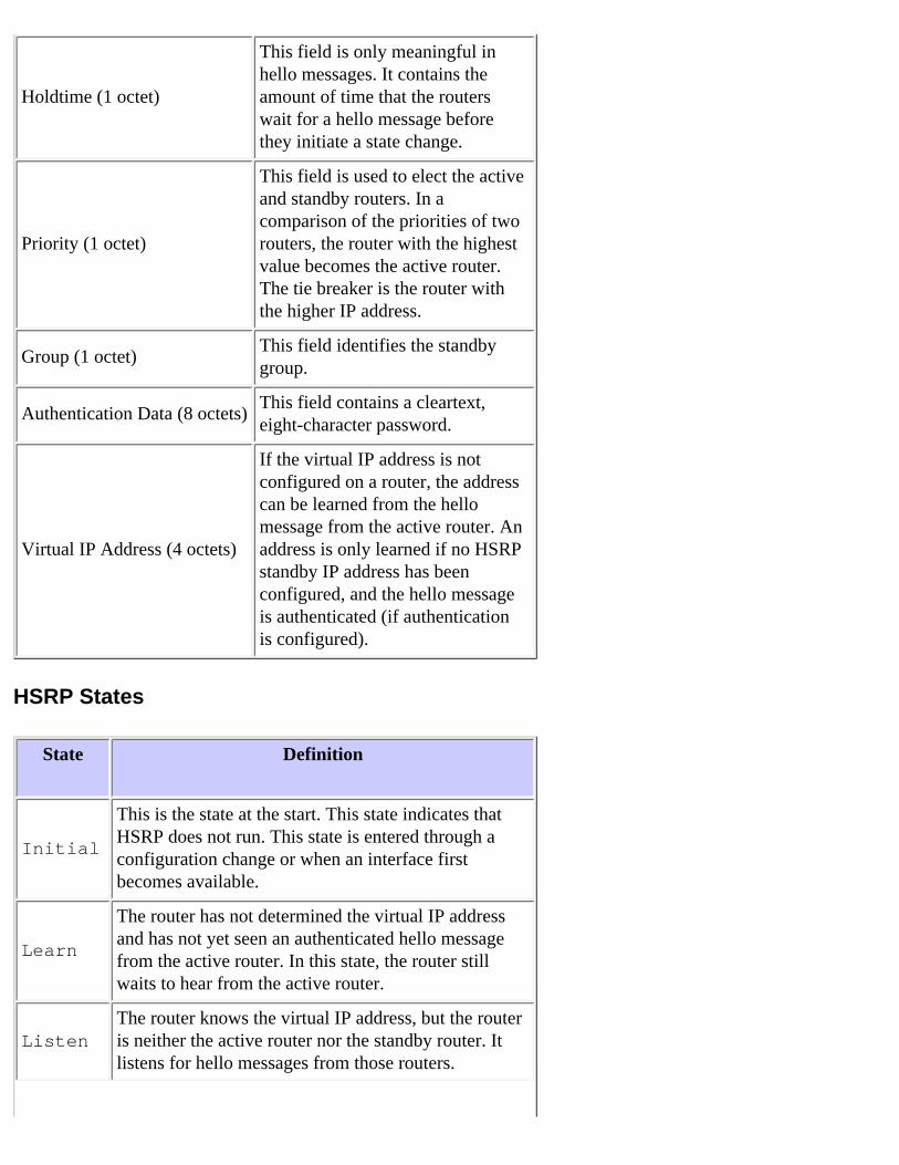
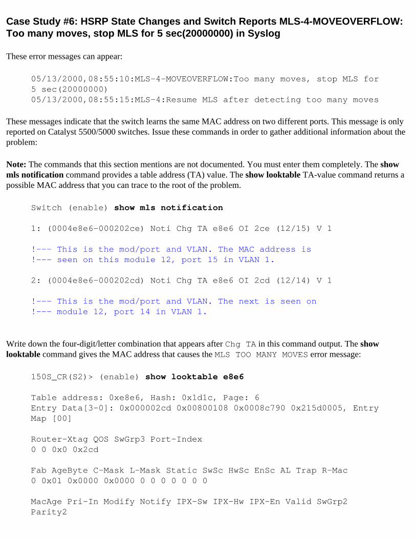

Host A ARP Table
Switch 1
MAC Address Table
MAC VLAN Port
MSFC1 ARP Table
MSFC2 ARP Table
Switch 2
MAC Address Table
MAC VLAN Port
Host B ARP Table
10111 00000c07ac01
00000c000001 1 21
101110 00000c000001
101210 00000c000002
00000c000002 2 21
10122 (00036bf12a01)
00000c000002 2 11
101210 00000c000001
10121 (00000c07ac02)
5 Host B now forwards the echo reply packet to MSFC2 MSFC2 sends an ARP request for host A because it is directly connected on VLAN 1 Switch 2 populates its MAC address table with the MAC address of host B
ARP and MAC Address Tables After Echo Packet Has Been Received by Host A
Host A ARP Table
Switch 1
MAC Address Table
MAC VLAN Port
MSFC1 ARP Table
MSFC2 ARP Table
Switch 2
MAC Address Table
MAC VLAN Port
Host B ARP Table
10111 00000c07ac01
00000c000001 1 21
101110 00000c000001
101210 00000c000002
00000c000002 2 21
10122 ( 00036bf12a01)
10113 00036bf12a0
00000c000002 2 11
101210 00000c000001
101110 00000c000001
00000c0000001 1 11
10121 (00000c07ac02)
6 The echo reply reaches host A and the flow is complete
Consequences of Asymmetric Routing
Consider the case of the continuous ping of host B by host A Remember that host A sends the echo packet to MSFC1 and host B sends the echo reply to MSFC2 which is in an asymmetric routing state The only time that Switch 1 learns the source MAC of host B is when host B replies to an ARP request from MSFC1 This is because
host B uses MSFC2 as its default gateway and does not send packets to MSFC1 and consequently Switch 1 Since the ARP timeout is four hours by default Switch 1 ages the MAC address of host B after five minutes by default Switch 2 ages host A after fiveminutes As a result Switch 1 must treat any packet with a destination MAC of host B as an unknown unicast The switch floods the packet that comes from host A and is destined for host B out all ports In addition because there is no MAC address entry host B in Switch 1 there is no MLS entry as well
ARP and MAC Address Tables After 5 Minutes of Continuous Ping of Host B by Host A
Host A ARP Table
Switch 1
MAC Address Table
MAC VLAN Port
MSFC1 ARP Table
MSFC2 ARP Table
Switch 2
MAC Address Table
MAC VLAN Port
Host B ARP Table
10111 00000c07ac01
00000c000001 1 21
101110 00000c000001
101210 00000c000002
00000c000002 2 21
10122 00036bf12a01
10113 00036bf12a0
101210 00000c000001
101110 00000c000001
10121 00000c07ac01
The echo reply packets that come from host B experience the same issue after the MAC address entry for host A ages on Switch 2 Host B forwards the echo reply to MSFC2 which in turn routes the packet and sends it out on VLAN 1 The switch does not have an entry host A in the MAC address table and must flood the packet out all ports in VLAN 1
Asymmetric routing issues do not break connectivity But asymmetric routing can cause excessive unicast flooding and MLS entries that are missing There are three configuration changes that can remedy this situation
Adjust the MAC aging time on the respective switches to 14400 seconds (four hours) or longer
Change the ARP timeout on the routers to five minutes (300 seconds)
Change the MAC aging time and ARP timeout to the same timeout value
The preferable method is to change the MAC aging time to 14400 seconds These are the configuration guidelines
CatOS
set cam agingtime vlan_aging_time_in_msec Cisco IOS Software2900XL3500XL
mac-address-table aging-time seconds [vlan vlan_id]
Case Study 9 HSRP Virtual IP Address Is Reported as a Different IP Address
The STANDBY-3-DIFFVIP1 error message occurs when there is interVLAN leakage because of bridging loops in the switch
If you get this error message and there is interVLAN leakage because of bridging loops in the switch complete these steps in order to resolve the error
1 Identify the path that the packets should take between end nodes
If there is a router on this path complete these steps
a Troubleshoot the path from the first switch to the router
b Troubleshoot the path from the router to the second switch2 Connect to each switch on the path and check the status of the ports that are used on the path between end
nodes
For more information on this error message and other HSRP error messages refer to the STANDBY Messages section of Cisco IOS System Error Messages Volume 2 of 2
Case Study 10 HSRP Causes MAC Violation on a Secure Port
When port security is configured on the switch ports that are connected to the HSRP enabled routers it causes a MAC violation since you cannot have the same secure MAC address on more than one interface A security violation occurs on a secure port in one of these situations
The maximum number of secure MAC addresses is added to the address table and a station whose MAC address is not in the address table attempts to access the interface
An address that is learned or configured on one secure interface is seen on another secure interface in the same VLAN
By default a port security violation causes the switch interface to become error-disabled and to shutdown immediately which blocks the HSRP status messages between the routers
Workaround
Issue the standby use-bia command on the routers This forces the routers to use a burned-in address for HSRP instead of the virtual MAC address
Disable port security on the switch ports that connect to the HSRP enabled routers
Case Study 11 Interface Hardware Cannot Support Multiple Groups
If multiple HSRP groups are created on the interface this error message is received
Interface hardware cannot support multiple groups
This error message is received due to the hardware limitation on some Routers or switches It is not possible to overcome the limitation by any software methods The problem is that each HSRP group uses one additional MAC address on interface so the Ethernet MAC chip must support multiple programmable MAC addresses in order to enable several HSRP groups
The workaround is to use the standby use-bia interface configuration command which uses the Burned-In Address (BIA) of the interface as its virtual MAC address instead of the preassigned MAC address
HSRP Troubleshooting Modules for CatOS Switches
A Verify HSRP Router Configuration
1 Verify Unique Router Interface IP Address
Verify that each HSRP router has a unique IP address for each subnet on a per-interface basis Also verify that each interface has the line protocol up In order to quickly verify the current state of each interface issue the show ip interface brief command Here is an example
Router_1show ip interface briefInterface IP-Address OK Method Status Protocol Vlan1 19216811 YES manual up up Vlan10 192168101 YES manual up up Vlan11 192168111 YES manual up up
Router_2show ip interface brief Interface IP-Address OK Method Status Protocol Vlan1 19216812 YES manual up up Vlan10 192168102 YES manual up up Vlan11 192168112 YES manual up up
2 Verify Standby (HSRP) IP Addresses and Standby Group Numbers
Verify that the configured standby (HSRP) IP addresses and standby group numbers match each HSRP-participating router A mismatch of standby groups or HSRP standby addresses can cause HSRP problems The show standby command details the standby group and standby IP address configuration of each interface Here is an example
Router_1show standbyVlan10 - Group 10 Local state is Active priority 110 may preempt Hellotime 3 holdtime 10 Next hello sent in 000000216 Hot standby IP address is 19216810100 configured Active router is local Standby router is 192168102 expires in 000008 Standby virtual mac address is 00000c07ac0a 8 state changes last state change 001804 Vlan11 - Group 11 Local state is Active priority 110 may preempt Hellotime 3 holdtime 10 Next hello sent in 000001848 Hot standby IP address is 19216811100 configured Active router is local Standby router is 192168112 expires in 000008 Standby virtual mac address is 00000c07ac0b 2 state changes last state change 000445
Router_2show standbyVlan10 - Group 10 Local state is Standby priority 109 may preempt Hellotime 3 holdtime 10 Next hello sent in 000001710 Hot standby IP address is 19216810100 configured Active router is 192168101 expires in 000009 priority 110 Standby router is local Standby virtual mac address is 00000c07ac0a 9 state changes last state change 002022 Vlan11 - Group 11 Local state is Standby priority 109 may preempt Hellotime 3 holdtime 10 Next hello sent in 000002506 Hot standby IP address is 19216811100 configured Active router is 192168111 expires in 000009 priority 110 Standby router is local Standby virtual mac address is 00000c07ac0b 4 state changes last state change 000707
3 Verify That Standby (HSRP) IP Address Is Different per Interface
Verify that the standby (HSRP) IP address is unique from the configured IP address on each interface The show standby command is a quick reference in order to view this information Here is an example
Router_1show standby Vlan10 - Group 10 Local state is Active priority 110 may preempt Hellotime 3 holdtime 10 Next hello sent in 000000216 Hot standby IP address is 19216810100 configured Active router is local Standby router is 192168102 expires in 000008 Standby virtual mac address is 00000c07ac0a 8 state changes last state change 001804 Vlan11 - Group 11 Local state is Active priority 110 may preempt Hellotime 3 holdtime 10 Next hello sent in 000001848 Hot standby IP address is 19216811100 configured Active router is local Standby router is 192168112 expires in 000008 Standby virtual mac address is 00000c07ac0b 2 state changes last state change 000445
Router_2show standbyVlan10 - Group 10 Local state is Standby priority 109 may preempt Hellotime 3 holdtime 10 Next hello sent in 000001710 Hot standby IP address is 19216810100 configured Active router is 192168101 expires in 000009 priority 110 Standby router is local Standby virtual mac address is 00000c07ac0a 9 state changes last state change 002022 Vlan11 - Group 11 Local state is Standby priority 109 may preempt Hellotime 3 holdtime 10 Next hello sent in 000002506 Hot standby IP address is 19216811100 configured Active router is 192168111 expires in 000009 priority 110 Standby router is local Standby virtual mac address is 00000c07ac0b 4 state changes last state change 000707
4 When to Use the standy use-bia Command
Unless HSRP is configured on a Token Ring interface only use the standby use-bia command in special circumstances This command tells the router to use its BIA instead of the virtual HSRP MAC address for the HSRP group On a Token Ring network if source-route bridging (SRB) is in use the standby use-bia command allows the new active router to update the host Routing Information Field (RIF) cache with a gratuitous ARP But not all of the host implementations handle the gratuitous ARP correctly Another caveat for the standby use-bia command involves proxy ARP A standby router cannot cover for the lost proxy ARP database of the failed active router
5 Verify Access List Configuration
Verify that the access lists that are configured on all of the HSRP peers do not filter any HSRP addresses that are configured on their interfaces Specifically verify the multicast address that is used in order to send traffic to all of the routers on a subnet (224002) Also verify that the UDP traffic that is destined for the HSRP port 1985 is not filtered HSRP uses this address and port to send hello packets between peers Issue the show access-lists command as a quick reference to note the access lists that are configured on the router Here is an example
Router_1show access-listsStandard IP access list 77 deny 1671900 wildcard bits 00255255 permit anyExtended IP access list 144 deny pim 2380100 000255 any permit ip any any (58 matches)
6 Review Unique Router Configurations (MSM and 4232-L3)
Note The Multilayer Switch Module (MSM) for the Catalyst 65006000 and the 4232-L3 blade for the Catalyst 4000 have unique configurations When you troubleshoot HSRP issues verify the configuration of not only the 4232-L3 or MSM but also the adjoining switch port configuration If you neglect to configure the adjoining switch ports correctly HSRP instability and other connectivity issues can result The HSRP duplicated IP address error message is the most common message that is associated with incorrect configuration of these hardware modules
Refer to these documents for more information
Installation and Configuration Note for the Catalyst 4000 Layer 3 Services Module
Catalyst 6000 Family MSM InstallConfig Note
7 Additional HSRP Sample Configurations
Refer to these documents
Configuring Redundancy (Catalyst 6500 MSFC)
Using HSRP for Fault-Tolerant IP Routing
B Verify Catalyst Fast EtherChannel and Trunking Configuration
1 Verify Trunking Configuration
If a trunk is used in order to connect the HSRP routers verify the trunking configurations on the routers and switches There are five possible trunking modes
on
desirable
auto
off
nonegotiate
Verify that the trunking modes that are configured provide the desired trunking method Refer to Configuring Ethernet VLAN Trunks for a table that details the possible configuration modes
Use the desirable configuration for switch-to-switch connections when you troubleshoot HSRP issues This configuration can isolate issues where switch ports are unable to establish trunks correctly Set a router-to-switch configuration as nonegotiate because most Cisco IOS routers do not support negotiation of a trunk
For IEEE 8021Q (dot1q) trunking mode verify that both sides of the trunk are configured to use the same native VLAN Because Cisco products do not tag the native VLAN by default a mismatch of native VLAN configurations results in no connectivity on mismatched VLANs Lastly verify that the trunk is configured to carry the VLANs that are configured on the router and verify that the VLANs are not pruned and in the STP state for router-connected ports Issue the show trunk modport command for a quick reference that shows this information Here is an example
Switch_1gt (enable) show trunk 211Port Mode Encapsulation Status Native vlan -------- ----------- ------------- ------------ ----------- 211 desirable isl trunking 1 Port Vlans allowed on trunk -------- --------------------------------------------------------------------- 211 1-1005 Port Vlans allowed and active in management domain --------
--------------------------------------------------------------------- 211 1-2 Port Vlans in spanning tree forwarding state and not pruned -------- --------------------------------------------------------------------- 211 1-2
Switch_2gt (enable) show trunk 210Port Mode Encapsulation Status Native vlan -------- ----------- ------------- ------------ ----------- 210 desirable isl trunking 1 Port Vlans allowed on trunk -------- --------------------------------------------------------------------- 210 1-1005 Port Vlans allowed and active in management domain -------- --------------------------------------------------------------------- 210 1-2 Port Vlans in spanning tree forwarding state and not pruned -------- --------------------------------------------------------------------- 210 1-2
Switch_1gt (enable) show trunk 211 Port Mode Encapsulation Status Native vlan -------- ----------- ------------- ------------ ----------- 211 nonegotiate isl trunking 1 Port Vlans allowed on trunk -------- --------------------------------------------------------------------- 211 1-1005 Port Vlans allowed and active in management domain -------- --------------------------------------------------------------------- 211 1-2 Port Vlans in spanning tree forwarding state and not pruned -------- --------------------------------------------------------------------- 211 1-2
Switch_1gt (enable) show trunk 211 Port Mode Encapsulation Status Native vlan -------- ----------- ------------- ------------ ----------- 211 nonegotiate dot1q trunking 1 Port Vlans allowed on trunk -------- --------------------------------------------------------------------- 211 1-1005 Port Vlans allowed and active in management domain -------- --------------------------------------------------------------------- 211 1-2 Port Vlans in spanning tree forwarding state and not pruned -------- --------------------------------------------------------------------- 211 1-2
2 Verify Fast EtherChannel (Port Channeling) Configuration
If a port channel is used in order to connect the HSRP routers verify the EtherChannel configuration on both routers and switches Configure a switch-to-switch port channel as desirable on at least one side The other side can be in any of these modes
on
desirable
auto
Here is an example
Switch_1gt (enable) show port channelPort Status Channel Admin Ch Mode Group Id----- ---------- -------------------- ----- ----- 11 connected desirable silent 16 769 12 connected desirable silent 16 769----- ---------- -------------------- ----- ----- Port Device-ID Port-ID Platform----- ------------------------------- ------------------------- ---------------- 11 SCA031700TR 11 WS-C6509
12 SCA031700TR 12 WS-C6509----- ------------------------------- ------------------------- ---------------- Switch_2gt (enable) show port channelPort Status Channel Admin Ch Mode Group Id----- ---------- -------------------- ----- ----- 11 connected desirable silent 29 769 12 connected desirable silent 29 769----- ---------- -------------------- ----- ----- Port Device-ID Port-ID Platform----- ------------------------------- ------------------------- ---------------- 11 TBA03501066 11 WS-C6506 12 TBA03501066 12 WS-C6506----- ------------------------------- ------------------------- ----------------
3 Additional Channeling and Trunking Sample Configurations
Refer to these documents
Configuring EtherChannel Between Catalyst 45004000 55005000 and 65006000 Switches That Run CatOS System Software
Configuring Etherchannel (CatOS software)
Configuring Layer 3 and Layer 2 EtherChannel (Cisco IOS Software)
4 Investigate Switch MAC Address Forwarding Table
Verify that the MAC address table entries exist on the switch for the HSRP routers for the HSRP virtual MAC address and the physical BIAs The show standby command on the router provides the virtual MAC address The show interface command provides the physical BIA Here are sample outputs
Router_1show standby Vlan1 - Group 1 Local state is Active priority 100 Hellotime 3 holdtime 10 Next hello sent in 000001820 Hot standby IP address is 1011254 configured Active router is local
Standby router is 10112 expires in 000007 Standby virtual mac address is 00000c07ac01 2 state changes last state change 005015 Vlan2 - Group 2 Local state is Active priority 200 may preempt Hellotime 3 holdtime 10 Next hello sent in 000000724 Hot standby IP address is 1021254 configured Active router is local Standby router is 10212 expires in 000009 Standby virtual mac address is 00000c07ac02 6 state changes last state change 000759Switch_1gt (enable) show cam 00-00-0c-07-ac-01 = Static Entry + = Permanent Entry = System Entry R = Router Entry X = Port Security EntryVLAN Dest MACRoute Des [CoS] Destination Ports or VCs [Protocol Type] ---- ------------------ ----- ------------------------------------------- 1 00-00-0c-07-ac-01 R 151 [ALL]Total Matching CAM Entries Displayed = 1 Switch_1gt (enable) show cam 00-00-0c-07-ac-02 = Static Entry + = Permanent Entry = System Entry R = Router Entry X = Port Security EntryVLAN Dest MACRoute Des [CoS] Destination Ports or VCs [Protocol Type] ---- ------------------ ----- ------------------------------------------- 2 00-00-0c-07-ac-02 R 151 [ALL] Total Matching CAM Entries Displayed = 1
Be sure to check the CAM aging time in order to determine how quickly the entries are aged If the time equals the configured value for STP forward delay which is 15 seconds by default there is a strong possibility that there is an STP loop in the network Here is sample command output
Switch_1gt (enable) show cam agingtime VLAN 1 aging time = 300 sec VLAN 2 aging time = 300 secVLAN 1003 aging time = 300 sec VLAN 1005 aging time = 300 sec Switch_2gt (enable) show cam agingtime VLAN 1 aging time = 300 sec VLAN 2 aging time = 300 sec VLAN 1003 aging time = 300 sec VLAN 1005 aging time = 300 sec
C Verify Physical Layer Connectivity
If more than one router in an HSRP group becomes active those routers do not consistently receive the hello packets from fellow HSRP peers Physical layer problems can prevent the consistent pass of traffic between peers and cause this scenario Be sure to verify physical connectivity and IP connectivity between HSRP peers when you troubleshoot HSRP Issue the show standby command in order to verify connectivity Here is an example
Router_1show standbyVlan10 - Group 10 Local state is Active priority 110 may preempt Hellotime 3 holdtime 10 Hot standby IP address is 19216810100 configured Active router is local Standby router is unknown expired Standby virtual mac address is 00000c07ac0a 12 state changes last state change 000048 Vlan11 - Group 11 Local state is Active priority 110 may preempt Hellotime 3 holdtime 10 Hot standby IP address is 19216811100 configured Active router is local Standby router is unknown expired Standby virtual mac address is 00000c07ac0b 6 state changes last state change 000048 Router_2show standbyVlan10 - Group 10 Local state is Active priority 109 may preempt Hellotime 3 holdtime 10 Hot standby IP address is 19216810100 configured Active router is local Standby router is unknown expired Standby virtual mac address is 00000c07ac0a 15 state changes last state change 000118 Vlan11 - Group 11 Local state is Active priority 109 may preempt Hellotime 3 holdtime 10 Hot standby IP address is 19216811100 configured Active router is local Standby router is unknown expired Standby virtual mac address is 00000c07ac0b 10 state changes last state change 000118
1 Check Interface Status
Check the interfaces Verify that all HSRP-configured interfaces are upup as this example shows
Router_1show ip interface brief Interface IP-Address OK Method Status Protocol Vlan1 10111 YES manual administratively down down Vlan2 10211 YES manual up up Router_2show ip interface brief Interface IP-Address OK Method Status Protocol Vlan1 10112 YES manual up up Vlan2 10212 YES manual down down
If any interfaces are administratively downdown enter the configuration mode on the router and issue the no shutdown interface-specific command Here is an example
Router_1configure terminal Enter configuration commands one per line End with CNTLZ Router_1(config) interface vlan 1 Router_1(config-if) no shutdown Router_1(config-if) ^Z
Router_1show ip interface brief Interface IP-Address OK Method Status Protocol Vlan1 10111 YES manual up down Vlan2 10211 YES manual up up
If any interfaces are downdown or updown review the log for any interface change notifications For Cisco IOS Software-based switches these messages appear for link updown situations
LINK-3-UPDOWN Interface interface changed state to upLINK-3-UPDOWN Interface interface changed state to down Router_1show log 3d04h STANDBY-6-STATECHANGE Standby 0 Vlan2 state Active-gt Speak 3d04h LINK-5-CHANGED Interface Vlan2 changed state to down 3d04h LINEPROTO-5-UPDOWN Line protocol on Interface Vlan2 changed state to down
Inspect the ports cables and any transceivers or other devices that are between the HSRP peers Has anyone removed or loosened any connections Are there any interfaces that lose a link repeatedly Are the proper cable types used Check the interfaces for any errors as this example shows
Router_1show interface vlan2 Vlan2 is down line protocol is down Hardware is Cat5k RP Virtual Ethernet address is 0030f2c95638 (bia 0030f2c95638) Internet address is 1021124 MTU 1500 bytes BW 10000 Kbit DLY 1000 usec reliability 255255 txload 1255 rxload 1255 Encapsulation ARPA loopback not set ARP type ARPA ARP Timeout 040000 Last input 000000 output never output hang never Last clearing of show interface counters never Queueing strategy fifo Output queue 040 0 drops input queue 075 0 drops 5 minute input rate 0 bitssec 0 packetssec 5 minute output rate 0 bitssec 0 packetssec 155314 packets input 8259895 bytes 0 no buffer Received 0 broadcasts 0 runts 0 giants 0 throttles 0 input errors 0 CRC 0 frame 0 overrun 0 ignored 8185 packets output 647322 bytes 0 underruns 0 output errors 3 interface resets 0 output buffer failures 0 output buffers swapped out
2 Link Change and Port Errors
Check the switch ports link changes and other errors Issue these commands and review the output
show logging buffer
show port
show mac
These commands help you determine if there is a problem with connectivity between switches and other devices
These messages are normal for link updown situations
PAGP-5-PORTTOSTPPort [dec][dec] joined bridge port [dec][chars] PAGP-5-PORTFROMSTP Port [dec][dec] left bridge port [dec][chars]
Switch_1gt (enable) show logging buffer 2001 Jan 08 203724 PAGP-5-PORTTOSTPPort 21 joined bridge port
21 2001 Jan 08 203725 PAGP-5-PORTTOSTPPort 22 joined bridge port 22 2001 Jan 08 203725 PAGP-5-PORTTOSTPPort 23 joined bridge port 23 2001 Jan 08 203725 PAGP-5-PORTTOSTPPort 211 joined bridge port 211 2001 Jan 08 204639 PAGP-5-PORTTOSTPPort 212 joined bridge port 212 2001 Jan 08 204629 PAGP-5-PORTFROMSTPPort 211 left bridge port 211 2001 Jan 08 204629 PAGP-5-PORTFROMSTPPort 212 left bridge port 212 2001 Jan 08 204705 DTP-5-TRUNKPORTONPort 211 has become isl trunk 2001 Jan 08 205215 PAGP-5-PORTTOSTPPort 211 joined bridge port 211 2001 Jan 08 221824 DTP-5-TRUNKPORTONPort 212 has become isl trunk 2001 Jan 08 221834 PAGP-5-PORTTOSTPPort 212 joined bridge port 212
Issue the show port command in order to determine the general health of a port Here is an example
Switch_1gt (enable) show port status 211Port Name Status Vlan Level Duplex Speed Type ----- ------------------ ---------- ---------- ------ ------ ----- ------------ 211 connected trunk normal a-full a-100 10100BaseTX
Is the port status connected notconnect or errdisable If the status is notconnect check that the cable is plugged in on both sides Check that the proper cable is used If the status is errdisable review the counters for excessive errors Refer to Recovering From errDisable Port State on the CatOS Platforms for more information
For what VLAN is this port configured Be sure that the other side of the connection is configured for the same VLAN If the link is configured to be a trunk be sure that both sides of the trunk carry the same VLANs
What is the speed and duplex configuration If the setting is preceded by a- the port is configured to autonegotiate the speed and duplex Otherwise the network administrator has predetermined this configuration For configuration of the speed and duplex for a link the settings on both sides of the link must match If one switch port is configured for autonegotiation the other side of the link must also be configured for autonegotiation If one side is hard coded to a specific speed and duplex the other side must be hard coded as well If you leave one side to autonegotiate while the other side is hard coded you break the autonegotiation process
Switch_1gt (enable) show port counters 211 Port Align-Err FCS-Err Xmit-Err Rcv-Err UnderSize ----- ---------- ---------- ---------- ---------- --------- 211 0 0 0 0 0 Port Single-Col Multi-Coll Late-Coll Excess-Col Carri-Sen Runts Giants ----- ---------- ---------- ---------- ---------- --------- --------- --------- 211 0 0 0 0 0 0 - Last-Time-Cleared -------------------------- Fri Jan 5 2001 133045
Are there a lot of Align-Err FCS-Err or Runts These indicate a speed or duplex mismatch between the port and the connecting device Change the speed and duplex settings for that port in order to help correct these errors
Issue the show mac command in order to verify that the port is passing traffic The Rcv- and Xmit- columns indicate the number of unicast multicast and broadcast packets that are received and transmitted on a particular port The bottom counters reveal how many packets are discarded or lost and whether these packets are a part of inbound or outbound traffic Lrn-Discrd In-Lost and Out-Lost count the number of packets that are mistakenly forwarded or dropped due to insufficient buffers
Switch_1gt (enable) show mac 211 Port Rcv-Unicast Rcv-Multicast Rcv-Broadcast -------- -------------------- -------------------- -------------------- 211 9786 9939 2678Port Xmit-Unicast Xmit-Multicast Xmit-Broadcast -------- -------------------- -------------------- -------------------- 211 587 55517 148
Port Rcv-Octet Xmit-Octet -------- -------------------- -------------------- 211 2354136 7206386 MAC Dely-Exced MTU-Exced In-Discard Lrn-Discrd In-Lost Out-Lost -------- ---------- ---------- ---------- ---------- ---------- ---------- 211 0 - 13 0
0 0 Last-Time-Cleared -------------------------- Fri Jan 5 2001 133045
3 Verify IP Connectivity
Verify IP connectivity Issue an IP ping from the associated router This helps expose any momentary losses of connectivity An extended ping is only available in enable mode Here is sample command output
router_1ping Protocol [ip] Target IP address 10212 Repeat count [5] 1000 Datagram size [100] 1500 Timeout in seconds [2] Extended commands [n] Sweep range of sizes [n] Type escape sequence to abort Sending 1000 1500-byte ICMP Echos to 10212 timeout is 2 seconds Success rate is 100 percent (10001000) round-trip minavgmax = 4420 ms
Issue the ping from each HSRP router to its peers in order to determine the location of the failure in connectivity
4 Check for Unidirectional Link
Check the switch for unidirectional links between HSRP peers A unidirectional link occurs whenever traffic that a local device transmits over a link is received by the neighbor but traffic that the neighbor transmits is not received by the local device Later versions of CatOS have a feature that can detect a unidirectional link This feature is
known as UniDirectional Link Detection (UDLD) aggressive mode Use of UDLD is only possible if both sides of the connection support the feature UDLD aggressive mode operates at L2 to determine if a link is connected correctly and if traffic flows bidirectionally between the right neighbors You can configure UDLD aggressive mode in CatOS release 54(3) and later for point-to-point connections on a port-by-port basis Refer to Configuring UDLD for more information Here are sample command outputs
Note Enablement of UDLD without enablement of UDLD aggressive mode only checks for incorrectly wired fiber cable In this case UDLD checks where the receive and transmit are crossed among multiple connections
Switch_1gt (enable) set udld enable UDLD enabled globally Consolegt (enable) set udld aggressive-mode enable 11-2Aggressive UDLD enabled on ports 11-2Consolegt (enable) show udld UDLD enabled Message Interval 15 seconds
Consolegt (enable) show udld port 1UDLD enabledMessage Interval 15 secondsPort Admin Status Aggressive Mode Link State-------- ------------ --------------- ----------------11 enabled enabled undetermined12 enabled enabled undetermined
In CatOS 543 and earlier in which the switch does not support UDLD or if the link in question has a router on one end you can enable Cisco Discovery Protocol (CDP) Enablement of CDP is another way to detect if a unidirectional link exists If only one side of a link can see its neighbor device replace the cable between the devices and check for faulty interfaces Refer to Configuring CDP for more information
Switch_1gt (enable) show cdp CDP enabledMessage Interval 60 Hold Time 180 Switch_1gt (enable) show cdp neighbors - indicates vlan mismatch - indicates duplex mismatch Port Device-ID Port-ID Platform -------- ------------------------------- ------------------------- ------------ 25 066560091(Switch_2) 29 WS-C5505 26 066560091(Switch_2) 210 WS-C5505 151 Router_1 Vlan1
cisco Cat5k-RSFC
Switch_2gt (enable) show cdp CDP enabledMessage Interval 60 Hold Time 180 Switch_2gt (enable) show cdp neighbors - indicates vlan mismatch - indicates duplex mismatch Port Device-ID Port-ID Platform -------- ------------------------------- ------------------------- ------------ 29 066565061(Switch_1) 25 WS-C5505 210 066565061(Switch_1) 26 WS-C5505 151 Router_2 Vlan1 cisco Cat5k-RSFC
5 Additional Physical Layer Troubleshooting References
Refer to these documents
Configuring and Troubleshooting Ethernet 101001000Mb HalfFull Duplex Auto-Negotiation
Recovering From errDisable Port State on the CatOS Platforms
Troubleshooting Cisco Catalyst Switches to NIC Compatibility Issues
The Understanding Data Link Errors section of Troubleshooting Cisco Catalyst Switches to NIC Compatibility Issues
Troubleshooting Switch Port and Interface Problems
D Layer 3 HSRP Debugging
If the HSRP state changes are frequent use the HSRP debug commands in enable mode on the router in order to watch HSRP activity This information helps you determine what HSRP packets are received and sent by the router Gather this information if you create a service request with Cisco Technical Support The debug output also shows HSRP state information along with detailed HSRP hello packet accounts
1 Standard HSRP Debugging
In Cisco IOS Software Release 121 and earlier the HSRP debug command is simply debug standby This
information is useful where problems are intermittent and affect only a few interfaces The debug enables you to determine if the HSRP router in question receives and transmits HSRP hello packets at specific intervals If the router does not receive hello packets you can infer that either the peer does not transmit the hello packets or the network drops the packets
Command Purpose
debug standby Enables HSRP debugging
Here is sample command output
Router_1debug standby HSRP debugging is on
Router_1 4d01h SB1 Vlan1 Hello out 10111 Active pri 100 ip 1011254 4d01h SB1 Vlan1 Hello in 10112 Standby pri 100 ip 1011254 4d01h SB2 Vlan2 Hello in 10212 Standby pri 100 ip 1021254 4d01h SB2 Vlan2 Hello out 10211 Active pri 100 ip 1021254
2 Conditional HSRP Debugging (Limiting Output Based on Standby Group andor VLAN)
Cisco IOS Software Release 120(3) introduced a debug condition to allow the output from the debug standby command to be filtered based on interface and group number The command utilizes the debug condition paradigm that was introduced in Cisco IOS Software Release 120
Command Purpose
debug condition standby interface_group
Enables HSRP conditional debugging of the group (0ndash255)
The interface must be a valid interface that can support HSRP The group can be any group from 0 through 255 A debug condition can be set for groups that do not exist This allows debugs to be captured during the initialization of a new group Debug standby must be enabled in order to produce any debug output If no standby debug conditions exist debug output is produced for all groups on all interfaces If at least one standby debug condition exists standby debug output is filtered based on all of the standby debug conditions Here is sample command output
Router_1debug condition standby vlan 2 2 Condition 1 set
Router_1 4d01h Vl2 SB2 Debug Condition 1 standby Vl2 SB2 triggered count 1 Router_1debug standby HSRP debugging is on Router_1 4d01h SB2 Vlan2 Hello in 10212 Standby pri 100 ip 1021254 4d01h SB2 Vlan2 Hello out 10211 Active pri 100 ip 1021254 4d01h SB2 Vlan2 Hello out 10211 Active pri 100 ip 1021254 4d01h SB2 Vlan2 Hello in 10212 Standby pri 100 ip 1021254
3 Enhanced HSRP Debugging
Cisco IOS Software Release 121(1) added enhanced HSRP debugging In order to help find useful information enhanced HSRP debugging limits the noise from periodic hello messages and includes additional state information This information is particularly useful when you work with a Cisco Technical Support engineer if you create a service request
Command Purpose
debug standby Displays all HSRP errors events and packets
debug standby errors Displays HSRP errors
debug standby events [[all] | [hsrp | redundancy | track]] [detail]
Displays HSRP events
debug standby packets [[all | terse] | [advertise | coup | hello | resign]] [detail]
Displays HSRP packets
Here is sample command output
Router_2debug standby terseHSRP HSRP Errors debugging is on HSRP Events debugging is on HSRP Packets debugging is on (Coup Resign) Router_2 003950 SB2 Vlan2 Standby cActive timer expired (10211) 003950 SB2 Vlan2 Standby -gt Active 003950 STANDBY-6-STATECHANGE Standby 2 Vlan2 state Standby -gt Active
004030 SB2 Vlan2 Standby router is 10211 004112 SB2 Vlan2 Active dStandby timer expired (10211) 004209 SB2 Vlan2 Coup in 10211 Listen pri 200 ip 1021254 004209 SB2 Vlan2 Active jCoup rcvd from higher pri router 004209 SB2 Vlan2 Active -gt Speak 004209 STANDBY-6-STATECHANGE Standby 2 Vlan2 state Active -gt Speak 004209 SB2 Vlan2 Active router is 10211 004219 SB2 Vlan2 Speak dStandby timer expired (unknown) 004219 SB2 Vlan2 Speak -gt Standby 004219 STANDBY-6-STATECHANGE Standby 2 Vlan2 state Speak -gt Standby
You can use interface andor HSRP group conditional debugging in order to filter this debug output
Command Purpose
debug condition interface interface Enables interface conditional debugging
debug condition standby interface_group
Enables HSRP conditional debugging
In this example the router joins a preexisting HSRP group
SB1 Ethernet02 Init aHSRP enabledSB1 Ethernet02 Active bHSRP disabled (interface down)SB1 Ethernet02 Listen cActive timer expired (unknown)SB1 Ethernet02 Active dStandby timer expired (10003)SB1 Ethernet02 Speak fHello rcvd from higher pri Speak routerSB1 Ethernet02 Active gHello rcvd from higher pri Active routerSB1 Ethernet02 Speak hHello rcvd from lower pri Active routerSB1 Ethernet02 Standby iResign rcvdSB1 Ethernet02 Active jCoup rcvd from higher pri routerSB1 Ethernet02 Standby kHello rcvd from higher pri Standby routerSB1 Ethernet02 Standby lHello rcvd from lower pri Standby routerSB1 Ethernet02 Active mStandby mac address changedSB1 Ethernet02 Active nStandby IP address configured
E Spanning Tree Troubleshooting
STP loop conditions or instability in a network can prevent proper communication of HSRP peers Because of this improper communication each peer becomes an active router STP loops can cause broadcast storms duplicated frames and MAC table inconsistency All of these problems affect the entire network and especially HSRP HSRP
error messages can be the first indication of an STP issue
When you troubleshoot STP you must understand the STP topology of the network on each VLAN You must determine what switch is the root bridge and which ports on the switch are on blocking and forwarding Because each VLAN has its own STP topology this information is very important on each VLAN
1 Verify Spanning Tree Configuration
Be sure that STP is configured on every switch and bridging device in the network Take note of where each switch believes the root bridge is located Also note the values of these timers
Root Max Age
Hello Time
Forward Delay
Issue the show spantree command in order to see all of this information By default the command shows this information for VLAN 1 But you can also see other VLAN information if you supply the VLAN number with the command This information is very useful when you troubleshoot STP issues
These three timers that you note in the show spantree output are learned from the root bridge These timers do not need to match the timers that are set on that specific bridge But be sure that the timers match the root bridge in the case that this switch becomes the root bridge at any point This match of the timers to the root bridge helps maintain continuity and ease of administration The match also prevents a switch with incorrect timers from crippling the network
Note Enable STP for all VLANs at all times regardless of whether there are redundant links in the network If you enable STP in nonredundant networks you prevent a breakage A breakage can occur if someone bridges switches together with hubs or other switches and accidentally creates a physical loop STP is also very useful in the isolation of specific problems If the enablement of STP affects the operation of something in the network there can be an existing problem that you need to isolate
Here is sample output of the show spantree command
Switch_1gt (enable) show spantreeVLAN 1 Spanning tree enabled Spanning tree type ieee
Designated Root 00-01-64-34-90-00 Designated Root Priority 98Designated Root Cost 0 Designated Root Port 10 Root Max Age 20 sec Hello Time 2 sec Forward Delay 15 sec
Bridge ID MAC ADDR 00-01-64-34-90-00 Bridge ID Priority 98 Bridge Max Age 20 sec Hello Time 2 sec Forward Delay 15 sec
Port Vlan Port-State Cost Priority Portfast Channel_id ------------------------ ---- ------------- ----- -------- ---------- ---------- 11 1 not-connected 4 32 disabled 0 12 1 not-connected 4 32 disabled 0 21 1 forwarding 100 32 disabled 0 22 1 not-connected 100 32 disabled 0 23 1 not-connected 100 32 disabled 0 24 1 not-connected 100 32 disabled 0 25-6 1 forwarding 12 32 disabled 803 210 1 not-connected 100 32 disabled 0 211 1 not-connected 100 32 disabled 0 212 1 not-connected 100 32 disabled 0 151 1 forwarding 5 32 disabled 0
Switch_1gt (enable) show spantree 2 VLAN 2 Spanning tree enabled Spanning tree type ieee
Designated Root 00-30-96-73-74-01 Designated Root Priority 8192 Designated Root Cost 12 Designated Root Port 25-6 (agPort 1335) Root Max Age 20 sec Hello Time 2 sec Forward Delay 15 sec
Bridge ID MAC ADDR 00-01-64-34-90-01 Bridge ID Priority 16384 Bridge Max Age 20 sec Hello Time 2 sec Forward Delay 15 sec
Port Vlan Port-State Cost Priority Portfast Channel_id ------------------------ ---- ------------- ----- -------- ---------- ---------- 25-6 2 forwarding 12 32 disabled 803 27 2 not-connected 100 32 disabled 0 28 2 not-connected 100 32 disabled 0 29 2 not-connected 100 32 disabled 0 151 2 forwarding 5 32 disabled 0
Switch 1 is the root of VLAN 1 and believes that Switch 2 is the root of VLAN 2 Switch 2 concurs
Switch_2gt (enable) show spantree VLAN 1 Spanning tree enabled Spanning tree type ieee
Designated Root 00-01-64-34-90-00 Designated Root Priority 98 Designated Root Cost 12 Designated Root Port 29-10 (agPort 1337) Root Max Age 20 sec Hello Time 2 sec Forward Delay 15 sec
Bridge ID MAC ADDR 00-30-96-73-74-00 Bridge ID Priority 16384 Bridge Max Age 20 sec Hello Time 2 sec Forward Delay 15 sec
Port Vlan Port-State Cost Priority Portfast Channel_id ------------------------ ---- ------------- ----- -------- ---------- ---------- 11 1 not-connected 4 32 disabled 0 12 1 not-connected 4 32 disabled 0 26 1 not-connected 100 32 disabled 0 27 1 not-connected 100 32 disabled 0 28 1 not-connected 100 32 disabled 0
29-10 1 forwarding 12 32 disabled 805 211 1 not-connected 100 32 disabled 0 212 1 not-connected 100 32 disabled 0 151 1 forwarding 5 32 disabled 0
Switch_2gt (enable) show spantree 2VLAN 2 Spanning tree enabled Spanning tree type ieee
Designated Root 00-30-96-73-74-01 Designated Root Priority 8192 Designated Root Cost 0 Designated Root Port 10Root Max Age 20 sec Hello Time 2 sec Forward Delay 15 sec
Bridge ID MAC ADDR 00-30-96-73-74-01 Bridge ID Priority 8192 Bridge Max Age 20 sec Hello Time 2 sec Forward Delay 15 sec
Port Vlan Port-State Cost Priority Portfast Channel_id ------------------------ ---- ------------- ----- -------- ---------- ---------- 21 2 not-connected 100 32 disabled 0 22 2 not-connected 100 32 disabled 0 23 2 not-connected 100 32 disabled 0 24 2 not-connected 100 32 disabled 0 25 2 not-connected 100 32 disabled 0 29-10 2 forwarding 12 32 disabled 805 151 2 forwarding 5 32 disabled 0
2 Spanning Tree Loop Conditions
In order for an STP loop to occur there must be L2 physical redundancy in the network An STP does not occur if there is no possibility of a physical loop condition Symptoms of an STP loop condition are
Total network outage
Loss of connectivity
The report by network equipment of high process and system utilization
The show system command helps you determine the system utilization of a particular switch The show system command denotes these items
Current traffic percentage
Peak traffic percentage
Date and time of the last peak
System utilization that is above 20 percent usually indicates a loop Utilization above seven percent indicates a possible loop But these percentages are only approximations The approximations vary somewhat with different hardware such as Supervisor Engine I versus Supervisor Engine IIIG or Catalyst 4000 versus Catalyst 6000
Here is sample output of the show system command
Switch_1gt (enable) show system PS1-Status PS2-Status Fan-Status Temp-Alarm Sys-Status Uptime dhms Logout ---------- ---------- ---------- ---------- ---------- -------------- --------- ok none ok off ok 5005816 20 min PS1-Type PS2-Type Modem Baud Traffic Peak Peak-Time ------------ ------------ ------- ----- ------- ---- ------------------------- WS-C5008B none disable 9600 0 70 Tue Jan 9 2001 165052 System Name System Location System Contact ------------------------ ------------------------ ------------------------ Switch_1
This output shows these items
The current traffic percentage 0
The peak traffic percentage 70
The date and time of the last peak
The system utilization of 70 percent indicates a possible loop at the time that the show system command output shows
A single VLAN that experiences an STP loop condition can congest a link and starve the other VLANs of bandwidth The show mac command notes which ports transmit or receive an excessive number of packets Excessive broadcast and multicast can indicate ports that are part of an STP loop This example output of the show mac command shows a high number of multicast and broadcast packets on port 211 Investigate this port As a general rule suspect a link of an STP loop condition any time that multicast or broadcast exceeds the number of unicast packets
Note The switch also counts STP bridge protocol data units (BPDUs) that are received and transmitted as multicast frames A port that is in the STP blocking state still transmits and receives STP BPDUs
Switch_1gt (enable) show mac Port Rcv-Unicast Rcv-Multicast Rcv-Broadcast -------- -------------------- -------------------- -------------------- 11 0 0 0 12 0 0 0 21 551277 296902 1025640 22 0 0 0 23 0 0 0 24 0 0 0 25 0 69541 0 26 0 44026 0 27 0 0 0 28 0 0 0 29 0 0 0 210 0 0 0 211 12836 5911986 1126018 212 6993144 177795414 19063645
Port Xmit-Unicast Xmit-Multicast Xmit-Broadcast -------- -------------------- -------------------- -------------------- 11 0 0 0 12 0 0 0 21 326122 1151895 431125 22 0 0 0 23 0 0 0 24 0 0 0 25 0 157414 0 26 10 652821 1 27 0 0 0 28 0 0 0 29 0 0 0 210 0 0 0 211 20969162 127255514 56002139 212 13598 7378244 3166
Port Rcv-Octet Xmit-Octet -------- -------------------- -------------------- 11 0 0 12 0 0 21 544904490 295721712 22 0 0 23 0 0 24 0 0 25 6997319 15860816 26 4787570 185054891 27 0 0 28 0 0 29 0 0 210 0 0 211 560753237 8058589649 212 6822964273 815810803
MAC Dely-Exced MTU-Exced In-Discard Lrn-Discrd In-Lost Out-Lost -------- ---------- ---------- ---------- ---------- ---------- ---------- 11 0 0 0 0 0 0 12 0 0 0 0 0 0 21 0 0 718920 0 0 0 22 0 0 0 0 0 0 23 0 0 0 0 0 0 24 0 0 0 0 0 0 25 0 - 3 0 1 0 26 0 - 0 0 0 0 27 0 0 0 0 0 0 28 0 0 0 0 0 0 29 0 0 0 0 0 0 210 0 0 0 0 0 0 211 0 0 67 0 0 0 212 0 0 869 0 3 0
Issue the session command in order to see the ATM and router counters
Last-Time-Cleared -------------------------- Fri Jan 5 2001 133045
3 Toplogy Change Notification
Another command that is vital to the diagnosis of STP issues is the show spantree statistics command This command tracks Topology Change Notification (TCN) messages back to the originator These messages sent as special BPDUs between switches indicate that there has been a topology change on a switch That switch sends a TCN out its root port The TCN moves upstream to the root bridge The root bridge then sends another special
BPDU a Topology Change Acknowledgement (TCA) out all of its ports The root bridge sets the TCN bit in the configuration BPDU This causes all nonroot bridges to set their MAC address table aging timer to the configuration STP forward delay
In order to isolate this problem access the root bridge for each VLAN and issue the show spantree statistics command for the switch-connected ports The last topology change occurred entry gives the time that the last TCN was received In this situation you are too late to see who issued the TCNs that can have caused the possible STP loop The topology change count entry gives you an idea about the number of TCNs that occur During an STP loop this counter can increment every minute Refer to Spanning Tree Protocol Problems and Related Design Considerations for more information This document contains more information on how to interpret the show spantree statistics command Other useful information includes
Port of the last TCN
Time of last TCN
Current count of TCNs
Here is sample command output
Switch_1gt (enable) show spantree statistics 25 1 Port 25 VLAN 1 SpanningTree enabled for vlanNo = 1 BPDU-related parameters port spanning tree enabled state forwarding port_id 0x8323 port number 0x323 path cost 12 message age (portVLAN) 20(20) designated_root 00-01-64-34-90-00 designated_cost 0 designated_bridge 00-01-64-34-90-00 designated_port 0x8323 top_change_ack FALSE config_pending FALSE port_inconsistency none PORT based information amp statistics config bpdus xmitted (portVLAN) 29660(357027) config bpdus received (portVLAN) 2(215721) tcn bpdus xmitted (portVLAN) 0(521) tcn bpdus received (portVLAN) 2(203) forward trans count 1 scp failure count 0 Status of Port Timers forward delay timer INACTIVE forward delay timer value 15
message age timer INACTIVE message age timer value 0 topology change timer INACTIVE topology change timer value 35 hold timer INACTIVE hold timer value 1 delay root port timer INACTIVE delay root port timer value 0 VLAN based information amp statistics spanningtree type ieee spanningtree multicast address 01-80-c2-00-00-00 bridge priority 98 bridge mac address 00-01-64-34-90-00 bridge hello time 2 sec bridge forward delay 15(15) sec topology change initiator 22 last topology change occurred Wed Jan 10 2001 181602 topology change FALSE topology change time 35 topology change detected FALSE topology change count 80 topology change last recvd from 00-10-7b-08-fb-94 Other port-specific info dynamic max age transitions 0 port bpdu ok count 0 msg age expiry count 0 link loading 1 bpdu in processing FALSE num of similar bpdus to process 1 received_inferior_bpdu FALSE next state 3 src mac count 0 total src mac count 0 curr_src_mac 00-00-00-00-00-00 next_src_mac 00-00-00-00-00-00 channel_src_mac 00-10-7b-08-e1-74 channel src count 0 channel ok count 0
This output shows that the last topology change occurred from device 00-10-7b-08-fb-94 off port 22 Next issue the same show spantree statistics command from the 00-10-7b-08-fb-94 device Here is an excerpt of the show spantree statistics output from the adjoining device
VLAN based information amp statistics spanningtree type ieee spanningtree multicast address 01-80-c2-00-00-00 bridge priority 98
bridge mac address 00-10-7b-08-fb-94 bridge hello time 2 sec bridge forward delay 15(15) sec topology change initiator 52 last topology change occurred Wed Jan 10 2001 181602 topology change FALSE topology change time 35 topology change detected FALSE topology change count 80 topology change last recvd from 00-00-00-00-00-00
The output notes the MAC address with all zeroes which means that this switch is the topology change initiator Port 52 is the port that transitioned states which is most likely because the port goesup and down If this port is attached to a PC or a single host be sure that STP PortFast is enabled on this port STP PortFast suppresses STP TCNs when a port transitions states
Refer to these documents for information about STP and how to troubleshoot link transitions that are associated with network interface cards (NICs)
Troubleshooting Cisco Catalyst Switches to NIC Compatibility Issues
Using PortFast and Other Commands to Fix Workstation Startup Connectivity Delays
Configuring and Troubleshooting Ethernet 101001000Mb HalfFull Duplex Auto-Negotiation
Understanding Spanning-Tree Protocol Topology Changes
Spanning Tree Protocol Problems and Related Design Considerations
4 Disconnected Blocked Ports
Because of the load-balancing nature of Fast EtherChannel (FEC) (port-channeling) FEC issues can contribute to both HSRP and STP problems When you troubleshoot STP or HSRP remove the configuration for any FEC connections After the configuration changes are in place issue the show spantree blockedports command on both switches Ensure that at least one of the ports starts blocking on either side of the connection Here is sample command output
Switch_1gt (enable) show spantree blockedports T = trunk g = group Ports Vlans ----- ---------- 26 (T) 2 Number of blocked ports (segments) in the system 1
Switch_2gt (enable) show spantree blockedports
T = trunk g = group Ports Vlans ----- ---------- 210 (T) 1 Number of blocked ports (segments) in the system 1
Refer to these documents for information about Fast EtherChannel
Understanding EtherChannel Load Balancing and Redundancy on Catalyst Switches
Configure EtherChannel Between Catalyst 45004000 55005000 and 65006000 Switches That Run CatOS System Software
5 Broadcast Suppression
Enable broadcast suppression in order to help cut down the impact from a broadcast storm A broadcast storm is one of the main side effects of an STP loop Refer to Configuring Broadcast Suppression for more information Here is sample command output
Switch_1gt (enable) set port broadcast 25 Packets per second Percentage Switch_1gt (enable) set port broadcast 25 10 Port(s) 21-12 broadcast traffic limited to 10 Switch_1gt (enable) show port broadcast 25 Port Broadcast-Limit Broadcast-Drop -------- --------------- -------------- 25 10 -
6 Console and Telnet Access
Console or Telnet traffic to the switch often becomes too sluggish to properly track down an offending device during an STP loop In order to force the network to recover instantly remove all redundant physical links After STP is allowed to reconverge on the new nonredundant topology reattach one redundant link at a time If the STP loop returns after you add one particular segment you have identified the offending devices
7 Spanning Tree Features Portfast UplinkFast and BackboneFast
Verify that PortFast UplinkFast and BackboneFast are configured properly When you troubleshoot STP issues disable all advanced STP (UplinkFast and BackboneFast) In addition verify that STP PortFast is only enabled on ports that are directly connected to nonbridging hosts Nonbridging hosts include user workstations and routers without bridge groups Do not enable PortFast on ports that are connected to hubs or other switches Here is sample command output
Switch_2gt (enable) show port spantree
Port(s) Vlan Port-State Cost Priority Portfast Channel_id ------------------------ ---- ------------- ----- -------- ---------- ---------- 11 1 not-connected 4 32 disabled 0 12 1 not-connected 4 32 disabled 0 21 2 not-connected 100 32 disabled 0 22 2 not-connected 100 32 disabled 0 23 2 not-connected 100 32 disabled 0 24 2 not-connected 100 32 disabled 0 25 2 not-connected 100 32 disabled 0 26 1 forwarding 19 32 disabled 0 27 1 not-connected 100 32 disabled 0 28 1 not-connected 100 32 disabled 0 29 1 blocking 19 32 disabled 0 29 2 forwarding 19 32 disabled 0 29 3 forwarding 19 32 disabled 0 29 1003 not-connected 19 32 disabled 0 29 1005 not-connected 19 4 disabled 0 210 1 blocking 19 32 disabled 0 210 2 forwarding 19 32 disabled 0 210 3 blocking 19 32 disabled 0 210 1003 not-connected 19 32 disabled 0 210 1005 not-connected 19 4 disabled 0211 2 forwarding 100 32 enabled 0 212 1 not-connected 100 32 disabled 0
151 1 forwarding 5 32 disabled 0 151 2 forwarding 5 32 disabled 0
Only enable UplinkFast on leaf-node switches Leaf-node switches are closet switches to which users directly connect UplinkFast is an STP optimization that is meant only for uplink ports to the distribution or core layer of the network Here is sample command output
Switch_1gt (enable) set spantree uplinkfast enable VLANs 1-1005 bridge priority set to 49152 The port cost and portvlancost of all ports set to above 3000 Station update rate set to 15 packets100ms uplinkfast all-protocols field set to off uplinkfast enabled for bridge Switch_1gt (enable) show spantree uplinkfast Station update rate set to 15 packets100ms uplinkfast all-protocols field set to off VLAN port list ----------------------------------------------- 1 22(fwd) 25-6 2 25(fwd) 26
Configure BackboneFast on all switches in the network BackboneFast is an STP optimization that alters the Max Age timer at the receipt of an inferior BPDU that the designated bridge sends Here is sample command output
Switch_1gt (enable) set spantree backbonefast enable Backbonefast enabled for all VLANsSwitch_1gt (enable) show spantree backbonefast Backbonefast is enabled
Refer to Configuring Spanning Tree PortFast UplinkFast BackboneFast and Loop Guard for more information about these CatOS features
8 BPDU Guard
When you enable PortFast BPDU guard a nontrunking PortFast-enabled port is moved into an errdisable state at the receipt of a BPDU on that port This feature helps you find ports that are incorrectly configured for PortFast The feature also detects where devices may reflect packets or interject STP BPDUs into the network When you troubleshoot STP issues enable this feature on all ports Here is an example on CatOS
Switch_1gt(enable) set spantree portfast bpdu-quard enableSpantree PortFast bpdu-guard enabled on this switch
9 VTP Pruning
When VTP Pruning is enabled in the network it can cause the devices of an HSRP group to go active This results in IP conflicts among the gateways and cause traffic issues Make sure the VLAN of any HSRP group is not pruned by VTP in the network
F CGMP Leave Processing and HSRP Interoperability
HSRP communicates to the destination MAC address of 01-00-5e-00-00-02 which is the same destination MAC address that IGMP fast-leave processing uses IGMP fast-leave processing is an IGMP Version 2 feature With CGMP leave processing enabled on Cisco switches all multicast traffic with the destination MAC address of 01-00-5e-00-00-02 is forwarded to the switch CPU If the packet is not an IGMP message the switch CPU regenerates the packet and sends the packet to all router ports Because HSRP uses the same destination multicast address all HSRP packets must first be sent to the switch CPU which then regenerates and sends the packets to all router ports Therefore when you troubleshoot HSRP problems disable CGMP leave processing between HSRP peers
Note The use of IGMP snooping on the Catalyst 6500 and 5500 with NetFlow Feature Card (NFFC) II does not have this issue
In order to determine if CGMP leave processing is enabled on CatOS switches issue the show cgmp leave command Here is an example
Switchgt (enable) show cgmp leaveCGMP disabledCGMP leave disabledFor Catalyst 2900XL3500XL switches issue the show cgmp state command
s-2924xl-27ashow cgmp stateCGMP is runningCGMP Fast Leave is not runningDefault router timeout is 300 sec
G Divide and Conquer
If all other attempts to isolate or resolve HSRP fail the divide and conquer method is the next approach This method helps isolate the network and components that make up the network Divide and conquer involves any one of the guidelines in this list
Note This list repeats some guidelines from other sections of this document
Create a test VLAN for HSRP and isolated VLAN to switch with HSRP routers
Disconnect all redundant ports
Break FEC ports into single connected ports
Reduce HSRP group members to only two members
Prune trunk ports such that only necessary VLANs propagate across those ports
Disconnect connected switches in the network until the problems cease
H High CPU with Asymmetric Traffic in HSRP
CPU usage might run high as traffic flows from a POS interface to a gigabit ethernet interface in an HSRP asymmetric environment Packets become fragmented as POS MTU size is 4470 bytes and Gig MTU size is 1500 bytes Fragmentation consumes more CPU
In order to resolve this issue execute one of these commands
--- On the gigabit interface
mtu 4770
or
--- On the POS interface
ip tcp adjust-mss 1460
Known Issues
Number of HSRP Groups Supported for Catalyst 65006000 Series PFC2MSFC2 and Catalyst 3550
The Policy Feature Card 2 (PFC2)MSFC2 for the Catalyst 65006000 series supports a maximum of 16 unique HSRP groups If you need more than 16 HSRP groups you can reuse the same HSRP group numbers in different VLANs For more information on HSRP group limitations for the Catalyst 65006000 series refer to HSRP Group Limitation on Catalyst 65006000 Series Switches Frequently Asked Questions
A similar limitation exists for the Catalyst 3550 series which supports a maximum of 16 HSRP groups This is a hardware limitation and there is no workaround
HSRP State FlappingUnstable When You Use Cisco 26202621 Cisco 3600 with Fast Ethernet or PA-2FEISL
This problem can occur with Fast Ethernet interfaces at the disruption of network connectivity or at the addition of an HSRP router with higher priority to a network When the HSRP state changes from active to speaking the router resets the interface in order to remove the HSRP MAC address from the interfaces MAC address filter Only specific hardware that is used on the Fast Ethernet interfaces for Cisco 2600s 3600s and 7500s have this issue The router interface reset causes a link state change on Fast Ethernet interfaces and the switch detects the change
If the switch runs STP the change causes an STP transition The STP takes 30 seconds to transition the port into the forwarding state This time is twice the default forward delay time of 15 seconds At the same time the speaking router transitions to the standby state after 10 seconds which is the HSRP hold time STP is not forwarding yet so no HSRP hello messages are received from the active router This causes the standby router to become active after about 10 seconds Both routers are now active When the STP ports become forwarding the lower-priority router changes from active to speaking and the whole process repeats
Platform Description Cisco Bug ID Fix Workaround
Cisco 26202621
Fast Ethernet interface starts to flap when HSRP is configured and the cable is unplugged
CSCdp57792 ( registered
customers only)
A software upgrade refer to the bug for revision details
Enables spanning tree PortFast on the connected switch port
Cisco 26202621
HSRP state is flapping on 2600 with Fast Ethernet
CSCdr02376 ( registered
customers only)
Cisco IOS Software Release 1213
Enables spanning tree PortFast on the connected switch port
Cisco 3600 with NM-1FE-TX1
HSRP state is flapping on 2600 and 3600 Fast Ethernet
CSCdr02376 ( registered
customers only)
Cisco IOS Software Release 1213
Enables spanning tree PortFast on the connected switch port
Cisco 4500 with Fast Ethernet interface
HSRP state is flapping on 4500 Fast Ethernet
CSCds16055 ( registered
customers only)
Cisco IOS Software Release 1215
Enables spanning tree PortFast on the connected switch port
Cisco 72007500 with PA-2FEISL2
HSRP state is flapping on PA-2FEISL
CSCdm89593 ( registered
customers only)
Cisco IOS Software Release 1215
Enables spanning tree PortFast on the connected switch port
1NM-1FE-TX = one-port Fast Ethernet (10100BASE-TX interface) network module
1 PA-2FEISL = two-port Fast Ethernet InterSwitch Link [ISL] port adapter
An alternative workaround is to adjust the HSRP timers so that the STP forward delay is less than half of the default HSRP hold time The default STP forward delay is 15 seconds and the default HSRP hold time is 10 seconds
When you use the track command under the HSRP process Cisco recommends that you use a particular decrement value in order to avoid the HSRP flap
Here is a sample configuration in an HSRP active router when you use the track command
standby 1 ip 10001 standby 1 priority 105 standby 1 preempt delay minimum 60 standby 1 name TEST standby 1 track Multilink100 15
Where 15 is the decrement value when the multilink100 flaps
HSRP Stuck in Initial or Active State on Cisco 26202621 Cisco 3600 with Fast Ethernet or PA-2FEISL
Fast Ethernet interfaces on the Cisco 2600 3600 and 7200 routers can experience these issues when HSRP is configured
HSRP remains in active state when the interface goes down or is unplugged
HSRP remains in initial state when the interface goes up
Interface tracking does not work
A timing-sense problem of interface updown causes these HSRP issues The timing problem is that there is a delay between the occurrence of the interface event and the update of the interface state of the router
Platform DescriptionCisco Bug
IDFix Workaround
Cisco 26202621
HSRP gets stuck in initial state
CSCdp24680
( registered customers only)
A software upgrade refer to the bug for revision details
Issue the shutdown and no shutdown commands in order to reset the interface
Cisco 3600 with NM-1FE-TX
HSRP gets stuck in initial state on the NM-1FE-TX module in 3600
CSCdp24680
( registered customers only)
A software upgrade refer to the bug for revision details
Issue the shutdown and no shutdown commands in order to reset the interface
Cisco 72007500 with PA-2FEISL
HSRP gets stuck in initial state on the PA-2FEISL module in 72007500
CSCdr01156
( registered customers only)
A software upgrade refer to the bug for revision details
Issue the shutdown and no shutdown commands in order to reset the interface
Unable to Ping HSRP Standby Address on Cisco 2500 and 4500 Series Routers
In this diagram Router A represents a Cisco 2500 series router and Router B represents a Cisco 4500 series router If Router A pings the virtual IP address on LAN 1 10111 the router first sends out an ARP request Router B responds with an ARP reply that contains the virtual MAC address Router B ignores this ARP reply because the virtual MAC address is the same as the Router B E1 interface address
There is a known restriction with the 10 MB Ethernet controller on the Cisco 2500 and 4500 series routers The Ethernet controller only supports a single MAC address in its address filter As a result only one HSRP group can be configured in an interface The HSRP MAC address is also used as the interface MAC address This causes problems when the same HSRP group is configured on different Ethernets on the same router The show standby command shows use of the MAC address as the HSRP MAC address
There are two workarounds to this issue
Configure different HSRP groups on different interfaces
Note This workaround is recommended
Issue the standby use-bia command on one or both interfaces
MLS Flows Are Not Created for Devices That Use HSRP Standby IP Address as Default Gateway
MLS switching can fail when HSRP is enabled and you use Cisco IOS Software Release 121(4)E on one of these
Supervisor Engine 1MSFC1
Supervisor Engine 2MSFC2
Supervisor Engine 1MSFC2
The symptoms are different for each combination as this list shows
For Supervisor Engine 1MSFC1 and Supervisor Engine 1MSFC2 (which use Netflow-MLS)mdashThe MLS shortcuts can fail to be created when traffic is sent to an HSRP MAC address Any client that uses the HSRP standby IP address as the default gateway uses the HSRP MAC address
For Supervisor Engine 2MSFC2 (which uses Cisco Express Forwarding-MLS)mdashThe Cisco Express Forwarding adjacency table can fail to be populated correctly on the switch
Refer to Cisco bug ID CSCds89040 ( registered customers only) The fix is available with Cisco IOS Software Release 121(5a)E for the CatOS (c6msfc) images and with Cisco IOS Software Release 121(5a)E1 for the Cisco IOS Software (c6sup) images
Catalyst 2948G 2980G 4912G 4003 and 4006 HSRP-CGMP Interoperability Issues
The Catalyst 4000 product line (2948G 2980G 4912G 4003 and 4006) software has several issues that relate to HSRP and CGMP interoperability All the issues are resolved in software versions 636 and 721
Enablement of CGMP can cause problems with HSRP This problem is resolved in software release 63(6) A
router in HSRP standby status is changed to active status When the status is restored the router does not go back to standby status from active status This problem is resolved in software release 63(6)
If you run HSRP and have enabled CGMP leave McastRx use can show at 25 percent CPU usage This problem occurs because CGMP leave and HSRP hello packets share the same destination MAC address The problem is resolved in software release 63(6)
Cisco Support Community - Featured Conversations
Cisco Support Community is a forum for you to ask and answer questions share suggestions and collaborate with your peers Below are just some of the most recent and relevant conversations happening right now
Want to see more Join us by clicking here
HSRPsystemseng4 Replies4 years 2 months ago
EIGRP Neighbors bouncinghttpssupportforumsciscocompeopleanthoney_murphy40gapcom2 Replies4 years 1 month ago
Problems with a Switch Catalyst 3560Kinai20081 Reply9 months 1 week ago
config HSRP on 6506 switch netman2k519 Replies4 years 9 months ago
Problems with a Switch Catalyst 3560Kinai20081 Reply9 months 6 days ago
Sub-interface amp HSRP on Catalyst 6509fchung2 Replies8 years 2 months ago
Firewall Module with HSRP switchesabuatiya1 Reply2 years 4 months ago
Troubleshooting SC0 in Catalyst 6500josephng4 Replies5 years 4 months ago
Connect a Server Cluster on 2 Cat 3550lscholer1 Reply7 years 3 months ago
Understanding how Networks are usedabraud2 Replies8 years 9 months ago Subscribe Start A New Discussion
Related Information
Hot Standby Router Protocol (HSRP) Support Page LAN Product Support LAN Switching Technology Support Technical Support amp Documentation - Cisco Systems
Contacts amp Feedback | Help | Site Map copy 2009 - 2010 Cisco Systems Inc All rights reserved Terms amp Conditions | Privacy Statement | Cookie Policy | Trademarks of Cisco Systems Inc
- AOAKMJDHBIGMOMJKDMHHILAICKJCAHID
-
- form1
-
- x
-
- f1 Off
- f2 This doc solved my problem(2015=yes2016=no2017=browsing)
- f3 Off
- f4
- f5 108
- f6 Cisco - Understanding and Troubleshooting HSRP Problems in Catalyst Switch Networks
- f7 httpkbasepawsservletViewFile1058362xmlconvertPaths=1
- f8
- f9 1
- f10 PAWS
- f11 UNKNOWN
- f12 UNKNOWN
- f13
- f14 right
- f15 false
-
- f16
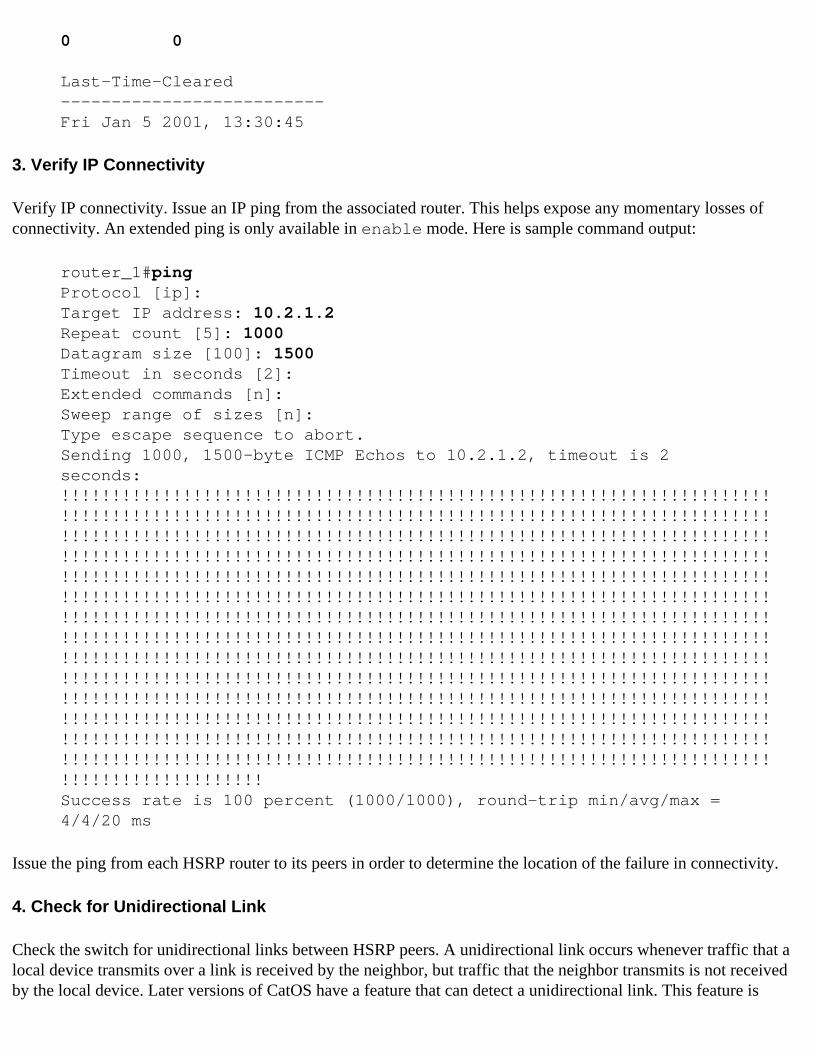
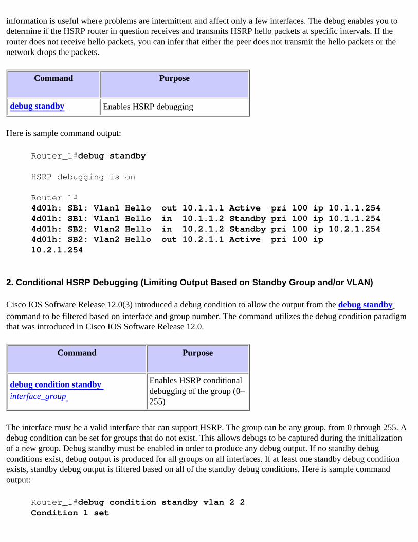
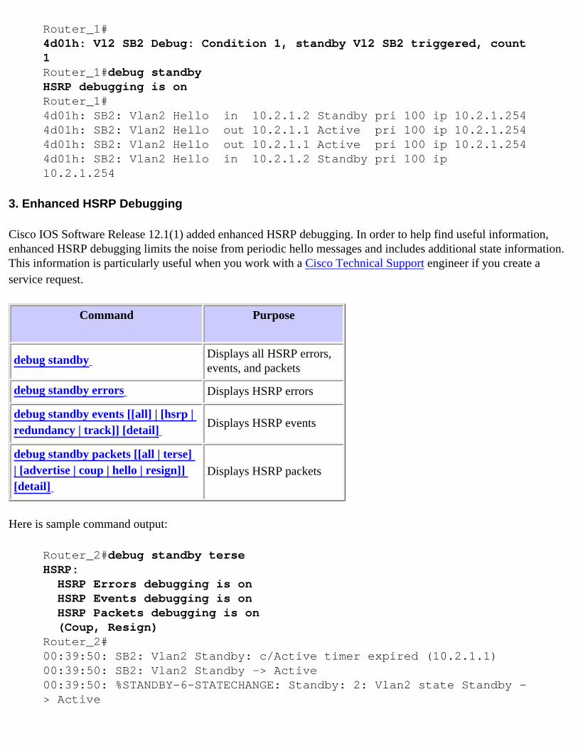
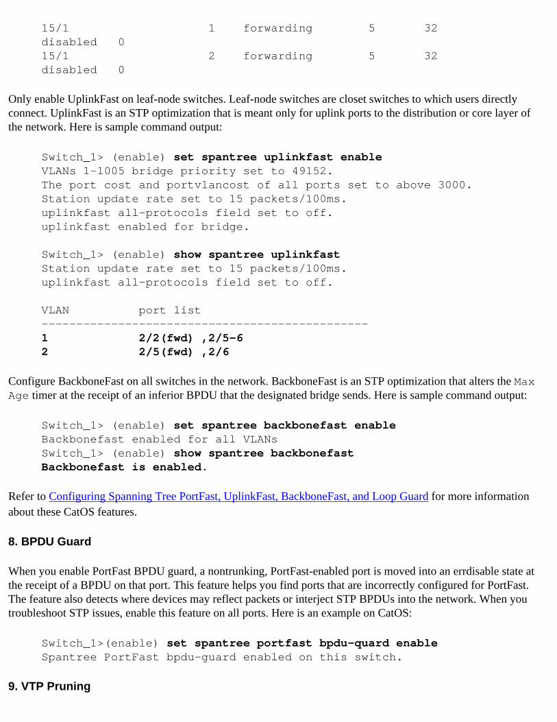
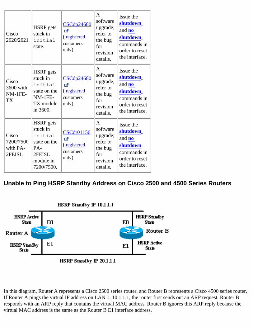