6200 Battery CE Operator Manual (EN) - Tennant...
78
6200 *330419* 330419 Rev. 14 (12-2015) (Battery) Sweeper English EN Operator Manual For the latest Parts manuals and other language Operator manuals, visit: www.tennantco.com/manuals
Transcript of 6200 Battery CE Operator Manual (EN) - Tennant...
6200
*330419*
330419Rev. 14 (12-2015)
(Battery)
SweeperEnglish EN
Operator Manual
For the latest Parts manuals and otherlanguage Operator manuals, visit:
www.tennantco.com/manuals
INTRODUCTION
This manual is furnished with each new model. It provides necessary operation and maintenance instructions.
Read this manual completely and understand the machine before operating or servicing it.
This machine will provide excellent service. However, the best results will be obtained at minimum costs if:
� The machine is operated with reasonable care.
� The machine is maintained regularly - per the machine maintenance instructions provided.
� The machine is maintained with manufacturer supplied or equivalent parts.
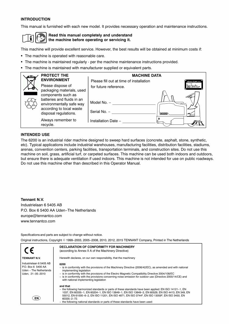
PROTECT THEENVIRONMENT
Please dispose ofpackaging materials, usedcomponents such asbatteries and fluids in anenvironmentally safe wayaccording to local wastedisposal regulations.
Always remember torecycle.
Model No. −
Serial No. −
Installation Date −
Please fill out at time of installation
for future reference.
MACHINE DATA
INTENDED USEThe 6200 is an industrial rider machine designed to sweep hard surfaces (concrete, asphalt, stone, synthetic,etc). Typical applications include industrial warehouses, manufacturing facilities, distribution facilities, stadiums,arenas, convention centers, parking facilities, transportation terminals, and construction sites. Do not use thismachine on soil, grass, artificial turf, or carpeted surfaces. This machine can be used both indoors and outdoors,but ensure there is adequate ventilation if used indoors. This machine is not intended for use on public roadways.Do not use this machine other than described in this Operator Manual.
Tennant N.V.Industrielaan 6 5405 ABP.O. Box 6 5400 AA Uden−The [email protected]
Specifications and parts are subject to change without notice.
Original instructions, Copyright � 1999−2003, 2005−2008, 2010, 2012, 2015 TENNANT Company, Printed in The Netherlands
DECLARATION OF CONFORMITY FOR MACHINERY (according to Annex II A of the Machinery Directive)
TENNANT N.V.
Industrielaan 6 5405 ABP.O. Box 6 5400 AAUden − The NetherlandsUden, 21−05−2010
EN
Herewith declares, on our own responsibility, that the machinery
6200− is in conformity with the provisions of the Machinery Directive (2006/42/EC), as amended and with national
implementing legislation− is in conformity with the provisions of the Electro Magnetic Compatibility Directive 2004/108/EC− is in conformity with the provisions concerning noise emission for outdoor use (Directive 2000/14/CE) and
with national implementing legislation
and that− the following harmonized standards or parts of these standards have been applied: EN ISO 14121−1, EN
1037, EN 60335−1, EN 60204−1, EN ISO 13849−1, EN ISO 13849−2, EN 60529, EN ISO 4413, EN 349, EN55012, EN 61000−6−2, EN ISO 11201, EN ISO 4871, EN ISO 3744*, EN ISO 13059*, EN ISO 3450, EN60335−2−72.
− the following national standards or parts of these standards have been used:
CONTENTS
16200 Battery 330419 (12−2015)
CONTENTS
PageCONTENTS 1. . . . . . . . . . . . . . . . . . . . . . . . . . . . .SAFETY PRECAUTIONS 2. . . . . . . . . . . . . . . . .OPERATION 5. . . . . . . . . . . . . . . . . . . . . . . . . . . .
OPERATOR RESPONSIBILITY 5. . . . . . . . .MACHINE COMPONENTS 6. . . . . . . . . . . . .SYMBOL DEFINITIONS 7. . . . . . . . . . . . . . . .CONTROLS AND INSTRUMENTS 8. . . . . .OPERATION OF CONTROLS 9. . . . . . . . . .
DIRECTIONAL PEDAL 9. . . . . . . . . . . . . .BRAKE PEDAL 10. . . . . . . . . . . . . . . . . . . .PARKING BRAKE PEDAL (For machines
below serial number 1069.) 10. . . . . . . .PARKING BRAKE (For machinesserial number 1069 and above.) 10. . . . . .LARGE DEBRIS TRAP PEDAL 10. . . . . . .MAIN BRUSH LEVER 11. . . . . . . . . . . . . . .MAIN BRUSH/VACUUM FAN AND
FILTER SHAKER SWITCH 11. . . . . . .POWER KILL SWITCH (OPTION) 11. . . .BATTERY DISCHARGE INDICATOR 12.STEERING WHEEL 12. . . . . . . . . . . . . . . .HOURMETER 12. . . . . . . . . . . . . . . . . . . . .ON−OFF KEY SWITCH 13. . . . . . . . . . . . .HORN BUTTON 13. . . . . . . . . . . . . . . . . . . .SIDE BRUSH LEVER 13. . . . . . . . . . . . . . .OPERATING LIGHTS SWITCH
(OPTION) 13. . . . . . . . . . . . . . . . . . . . . .OPERATING/HAZARD LIGHTS SWITCH
(OPTION) 14. . . . . . . . . . . . . . . . . . . . . .HOPPER SWITCH 14. . . . . . . . . . . . . . . . .HOPPER DOOR SWITCH 14. . . . . . . . . . .FUSES 15. . . . . . . . . . . . . . . . . . . . . . . . . . . .CIRCUIT BREAKERS 15. . . . . . . . . . . . . . .OPERATOR SEAT 16. . . . . . . . . . . . . . . . . .ADJUSTABLE OPERATOR SEAT
(OPTION) 16. . . . . . . . . . . . . . . . . . . . . .DELUXE SUSPENSION SEAT
(OPTION) 16. . . . . . . . . . . . . . . . . . . . . .HOPPER SUPPORT BAR 18. . . . . . . . . . .
HOW THE MACHINE WORKS 19. . . . . . . . . .PRE-OPERATION CHECKLIST 19. . . . . . . . .STARTING THE MACHINE 20. . . . . . . . . . . . .SWEEPING AND BRUSH INFORMATION 21SWEEPING 23. . . . . . . . . . . . . . . . . . . . . . . . . .STOP SWEEPING 25. . . . . . . . . . . . . . . . . . . .EMPTYING THE HOPPER 26. . . . . . . . . . . . .STOPPING THE MACHINE 28. . . . . . . . . . . .POST-OPERATION CHECKLIST 29. . . . . . . .ENGAGING HOPPER SUPPORT BAR 30. .DISENGAGING HOPPER SUPPORT BAR 32OPERATION ON INCLINES 33. . . . . . . . . . . .OPTIONS 34. . . . . . . . . . . . . . . . . . . . . . . . . . . .
VACUUM WAND 34. . . . . . . . . . . . . . . . . . .QUICK MOP 36. . . . . . . . . . . . . . . . . . . . . . .ROLLOUT BATTERY 38. . . . . . . . . . . . . . .
MACHINE TROUBLESHOOTING 43. . . . . . .MAINTENANCE 44. . . . . . . . . . . . . . . . . . . . . . . . .
MAINTENANCE CHART 44. . . . . . . . . . . . . . .LUBRICATION 46. . . . . . . . . . . . . . . . . . . . . . . .
STEERING GEAR CHAIN 46. . . . . . . . . . .STEERING CASTOR PIVOT BEARING 46
PageHYDRAULICS 47. . . . . . . . . . . . . . . . . . . . . . . .
HYDRAULIC FLUID RESERVOIR 47. . . .HYDRAULIC FLUID 48. . . . . . . . . . . . . . . .HYDRAULIC HOSES 48. . . . . . . . . . . . . . .
BATTERIES 49. . . . . . . . . . . . . . . . . . . . . . . . . .CHECKING THE ELECTROLYTE
LEVEL 49. . . . . . . . . . . . . . . . . . . . . . . . .MAINTENANCE−FREE BATTERIES 50. .CHECKING CONNECTIONS /
CLEANING 50. . . . . . . . . . . . . . . . . . . . .CHARGING THE BATTERIES 50. . . . . . .
BELTS AND CHAINS 52. . . . . . . . . . . . . . . . . .VACUUM FAN BELT 52. . . . . . . . . . . . . . . .MAIN BRUSH BELT 52. . . . . . . . . . . . . . . .STEERING GEAR CHAIN 53. . . . . . . . . . .STATIC DRAG CHAIN 53. . . . . . . . . . . . . .
DEBRIS HOPPER 54. . . . . . . . . . . . . . . . . . . . .HOPPER DUST FILTER 54. . . . . . . . . . . . .
REMOVING HOPPER DUST FILTER 55. . . . . . . . . . . . . . . . . . . . . .
THERMO SENTRY 58. . . . . . . . . . . . . . . . .BRUSHES 59. . . . . . . . . . . . . . . . . . . . . . . . . . . .
MAIN BRUSH 59. . . . . . . . . . . . . . . . . . . . . .REPLACING MAIN BRUSH 59. . . . . . .CHECKING AND ADJUSTING MAIN
BRUSH PATTERN 60. . . . . . . . . . . .SIDE BRUSH 62. . . . . . . . . . . . . . . . . . . . . .
REPLACING SIDE BRUSH 63. . . . . . .SIDE BRUSH GUARD 63. . . . . . . . . . . . . .
SKIRTS AND SEALS 64. . . . . . . . . . . . . . . . . .SIDE SKIRTS 64. . . . . . . . . . . . . . . . . . . . . .LARGE DEBRIS TRAP SKIRT 64. . . . . . .SIDE RECIRCULATION SKIRTS 64. . . . .REAR SKIRTS 65. . . . . . . . . . . . . . . . . . . . .HOPPER SEALS 66. . . . . . . . . . . . . . . . . . .HOPPER DOOR SEAL 66. . . . . . . . . . . . . .HOPPER LIP SEAL 66. . . . . . . . . . . . . . . . .VACUUM SEAL 67. . . . . . . . . . . . . . . . . . . .HOPPER FILTER SEALS 67. . . . . . . . . . . .
BRAKES AND TIRES 68. . . . . . . . . . . . . . . . . .BRAKES 68. . . . . . . . . . . . . . . . . . . . . . . . . .TIRES 69. . . . . . . . . . . . . . . . . . . . . . . . . . . .
ELECTRIC MOTORS 69. . . . . . . . . . . . . . . . . . .PUSHING, TOWING, AND TRANSPORTING
THE MACHINE 70. . . . . . . . . . . . . . . . . . . . .PUSHING OR TOWING THE MACHINE 70TRANSPORTING THE MACHINE 70. . . .
MACHINE JACKING 72. . . . . . . . . . . . . . . . . . .STORING MACHINE 72. . . . . . . . . . . . . . . . . .
SPECIFICATIONS 73. . . . . . . . . . . . . . . . . . . . . . .GENERAL MACHINE
DIMENSIONS/CAPACITIES 73. . . . . . . . .GENERAL MACHINE PERFORMANCE 73. . .POWER TYPE 74. . . . . . . . . . . . . . . . . . . . . . . .STEERING 74. . . . . . . . . . . . . . . . . . . . . . . . . . .HYDRAULIC SYSTEM 74. . . . . . . . . . . . . . . . .BRAKING SYSTEM (For machines
below serial number 1069.) 74. . . . . . . . . .TIRES 74. . . . . . . . . . . . . . . . . . . . . . . . . . . . . . .MACHINE DIMENSIONS 75. . . . . . . . . . . . . . .
SAFETY PRECAUTIONS
6200 Battery 330419 (12−2015)2
SAFETY PRECAUTIONS
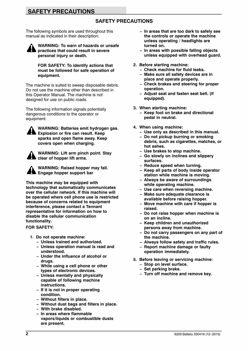
The following symbols are used throughout thismanual as indicated in their description:
WARNING: To warn of hazards or unsafepractices that could result in severepersonal injury or death.
FOR SAFETY: To identify actions thatmust be followed for safe operation ofequipment.
The machine is suited to sweep disposable debris.Do not use the machine other than described inthis Operator Manual. The machine is notdesigned for use on public roads.
The following information signals potentiallydangerous conditions to the operator orequipment:
WARNING: Batteries emit hydrogen gas.Explosion or fire can result. Keepsparks and open flame away. Keepcovers open when charging.
WARNING: Lift arm pinch point. Stayclear of hopper lift arms.
WARNING: Raised hopper may fall.Engage hopper support bar
This machine may be equipped withtechnology that automatically communicatesover the cellular network. If this machine willbe operated where cell phone use is restrictedbecause of concerns related to equipmentinterference, please contact a Tennantrepresentative for information on how todisable the cellular communicationfunctionality.
FOR SAFETY:
1. Do not operate machine:− Unless trained and authorized.− Unless operation manual is read and
understood.− Under the influence of alcohol or
drugs.− While using a cell phone or other
types of electronic devices.− Unless mentally and physically
capable of following machineinstructions.
− If it is not in proper operatingcondition.
− Without filters in place.− Without dust bags and filters in place.− With brake disabled.− In areas where flammable
vapors/liquids or combustible dustsare present.
− In areas that are too dark to safely seethe controls or operate the machineunless operating / headlights areturned on.
− In areas with possible falling objectsunless equipped with overhead guard.
2. Before starting machine:− Check machine for fluid leaks.− Make sure all safety devices are in
place and operate properly.− Check brakes and steering for proper
operation.− Adjust seat and fasten seat belt. (if
equipped).
3. When starting machine:− Keep foot on brake and directional
pedal in neutral.
4. When using machine:− Use only as described in this manual.− Do not pickup burning or smoking
debris, such as cigarettes, matches, orhot ashes.
− Use brakes to stop machine.− Go slowly on inclines and slippery
surfaces.− Reduce speed when turning.− Keep all parts of body inside operator
station while machine is moving.− Always be aware of surroundings
while operating machine.− Use care when reversing machine.− Make sure adequate clearance is
available before raising hopper.− Move machine with care if hopper is
raised.− Do not raise hopper when machine is
on an incline.− Keep children and unauthorized
persons away from machine.− Do not carry passengers on any part of
the machine.− Always follow safety and traffic rules.− Report machine damage or faulty
operation immediately.
5. Before leaving or servicing machine:− Stop on level surface.− Set parking brake.− Turn off machine and remove key.
SAFETY PRECAUTIONS
36200 Battery 330419 (12−2015)
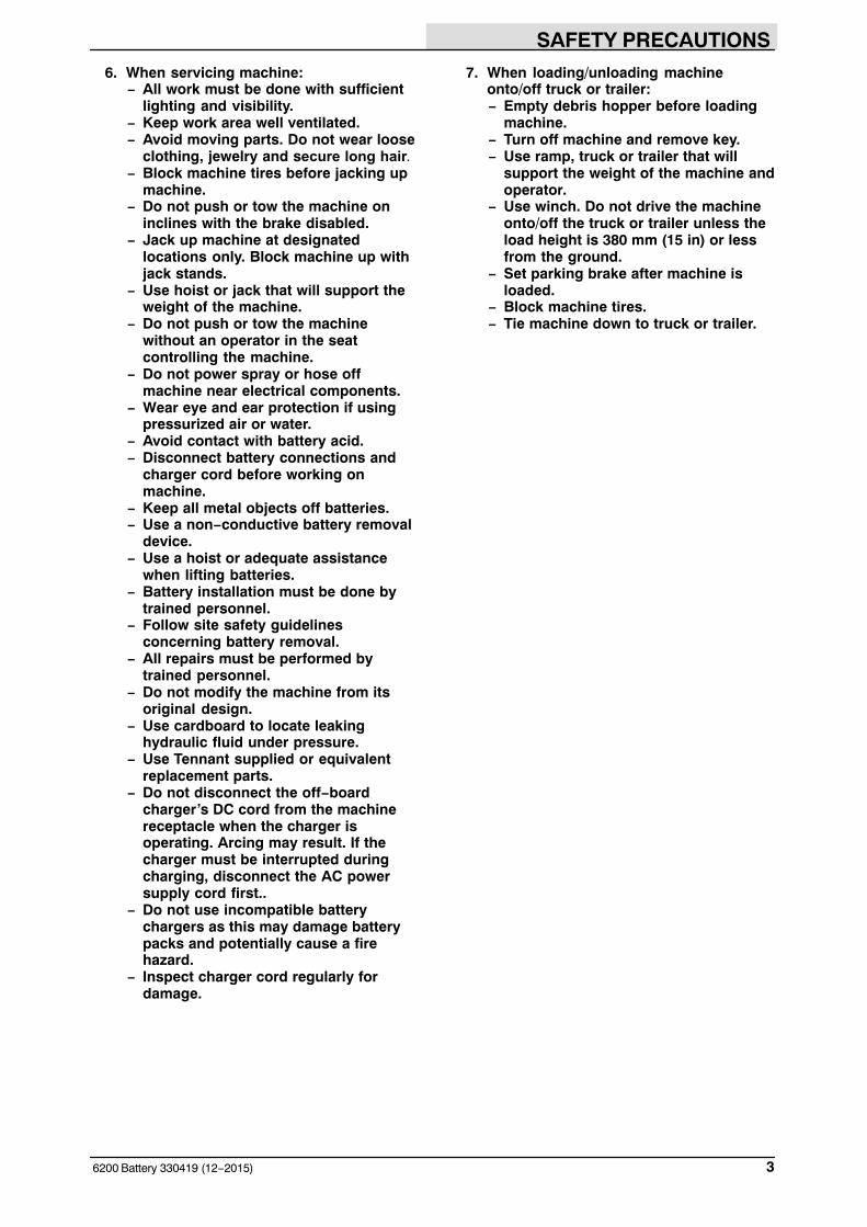
6. When servicing machine:− All work must be done with sufficient
lighting and visibility.− Keep work area well ventilated.− Avoid moving parts. Do not wear loose
clothing, jewelry and secure long hair.− Block machine tires before jacking up
machine.− Do not push or tow the machine on
inclines with the brake disabled.− Jack up machine at designated
locations only. Block machine up withjack stands.
− Use hoist or jack that will support theweight of the machine.
− Do not push or tow the machinewithout an operator in the seatcontrolling the machine.
− Do not power spray or hose offmachine near electrical components.
− Wear eye and ear protection if usingpressurized air or water.
− Avoid contact with battery acid.− Disconnect battery connections and
charger cord before working onmachine.
− Keep all metal objects off batteries.− Use a non−conductive battery removal
device.− Use a hoist or adequate assistance
when lifting batteries.− Battery installation must be done by
trained personnel.− Follow site safety guidelines
concerning battery removal.− All repairs must be performed by
trained personnel.− Do not modify the machine from its
original design.− Use cardboard to locate leaking
hydraulic fluid under pressure.− Use Tennant supplied or equivalent
replacement parts.− Do not disconnect the off−board
charger’s DC cord from the machinereceptacle when the charger isoperating. Arcing may result. If thecharger must be interrupted duringcharging, disconnect the AC powersupply cord first..
− Do not use incompatible batterychargers as this may damage batterypacks and potentially cause a firehazard.
− Inspect charger cord regularly fordamage.
7. When loading/unloading machineonto/off truck or trailer:− Empty debris hopper before loading
machine.− Turn off machine and remove key.− Use ramp, truck or trailer that will
support the weight of the machine andoperator.
− Use winch. Do not drive the machineonto/off the truck or trailer unless theload height is 380 mm (15 in) or lessfrom the ground.
− Set parking brake after machine isloaded.
− Block machine tires.− Tie machine down to truck or trailer.
SAFETY PRECAUTIONS
6200 Battery 330419 (9−1999)4
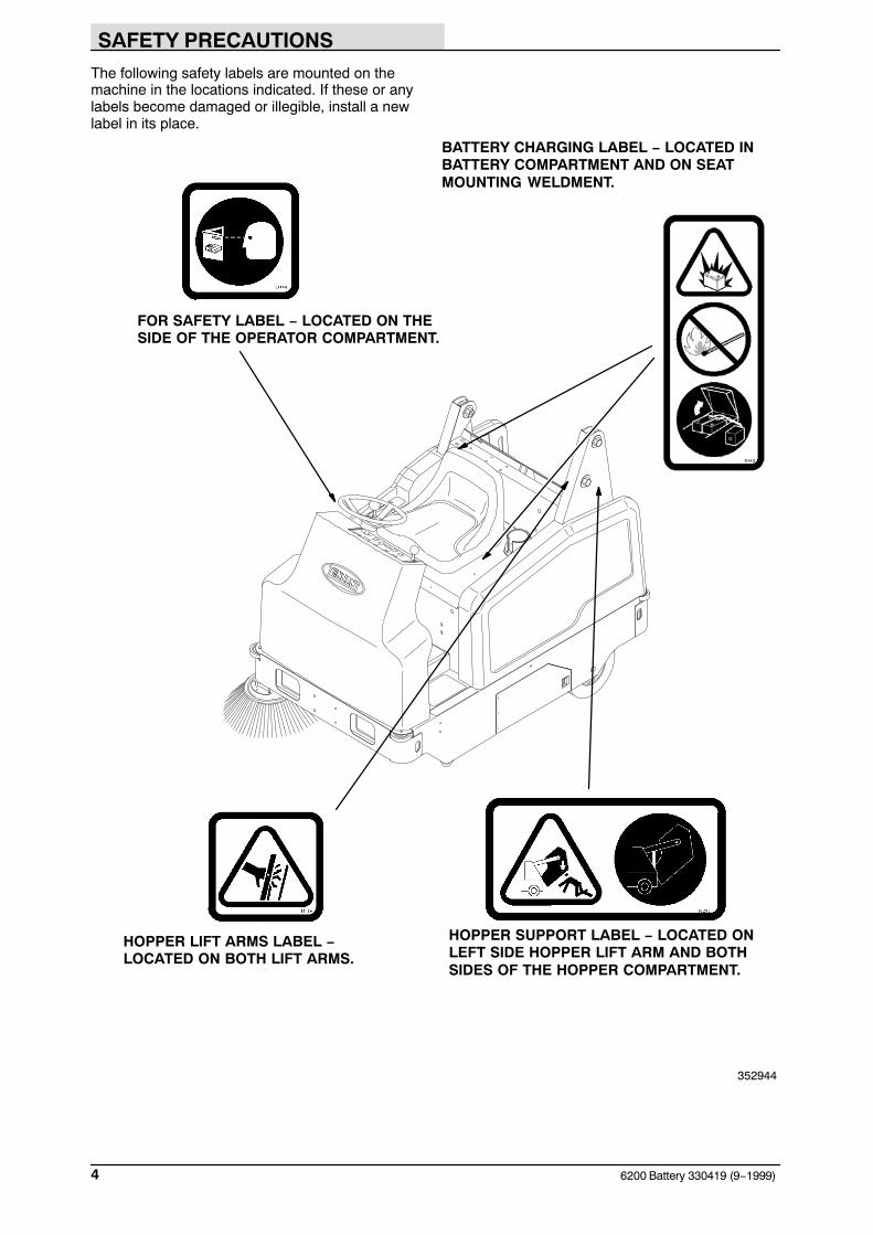
The following safety labels are mounted on themachine in the locations indicated. If these or anylabels become damaged or illegible, install a newlabel in its place.
FOR SAFETY LABEL − LOCATED ON THESIDE OF THE OPERATOR COMPARTMENT.
BATTERY CHARGING LABEL − LOCATED INBATTERY COMPARTMENT AND ON SEATMOUNTING WELDMENT.
HOPPER SUPPORT LABEL − LOCATED ONLEFT SIDE HOPPER LIFT ARM AND BOTHSIDES OF THE HOPPER COMPARTMENT.
HOPPER LIFT ARMS LABEL − LOCATED ON BOTH LIFT ARMS.
352944
OPERATION
56200 Battery 330419 (9−2002)
OPERATION
OPERATOR RESPONSIBILITY
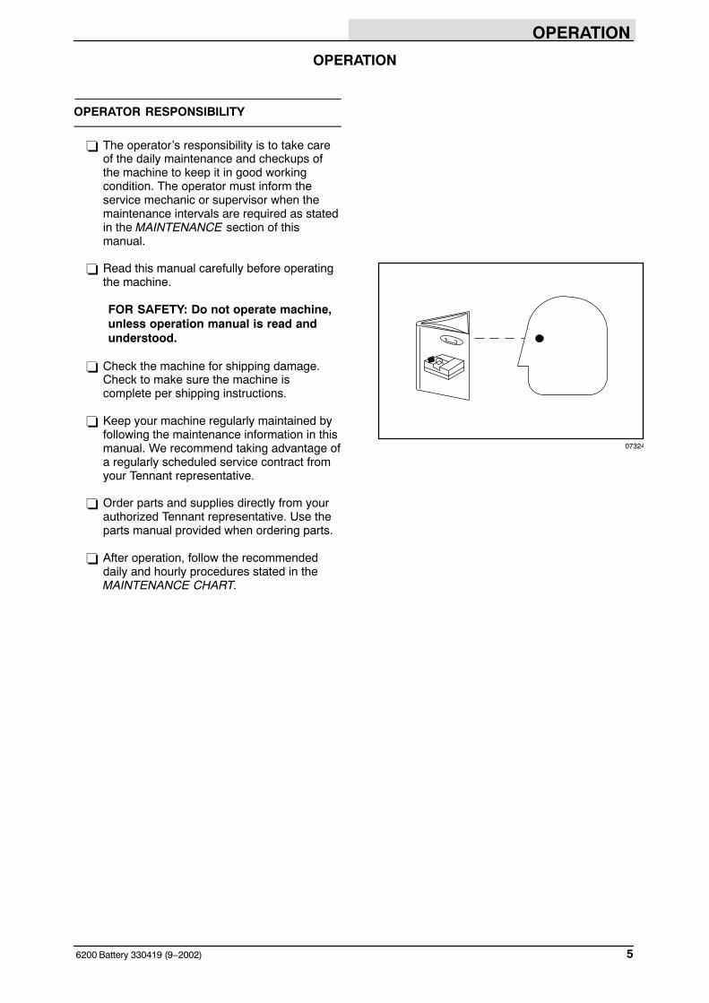
� The operator’s responsibility is to take careof the daily maintenance and checkups ofthe machine to keep it in good workingcondition. The operator must inform theservice mechanic or supervisor when themaintenance intervals are required as statedin the MAINTENANCE section of thismanual.
� Read this manual carefully before operatingthe machine.
FOR SAFETY: Do not operate machine,unless operation manual is read andunderstood.
� Check the machine for shipping damage.Check to make sure the machine iscomplete per shipping instructions.
� Keep your machine regularly maintained byfollowing the maintenance information in thismanual. We recommend taking advantage ofa regularly scheduled service contract fromyour Tennant representative.
� Order parts and supplies directly from yourauthorized Tennant representative. Use theparts manual provided when ordering parts.
� After operation, follow the recommendeddaily and hourly procedures stated in theMAINTENANCE CHART.
07324
OPERATION
6200 Battery 330419 (9−1999)6
MACHINE COMPONENTS
BC
A
E
G
F
D
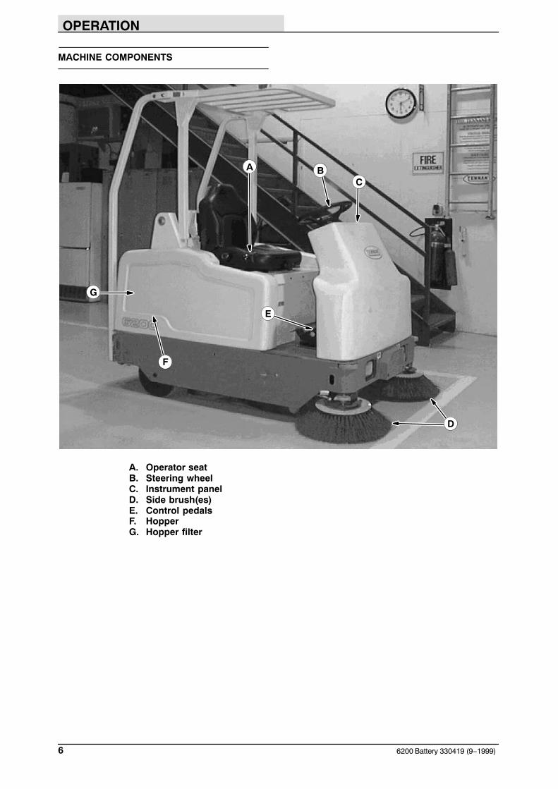
A. Operator seatB. Steering wheelC. Instrument panelD. Side brush(es)E. Control pedalsF. HopperG. Hopper filter
OPERATION
76200 Battery 330419 (9−1999)
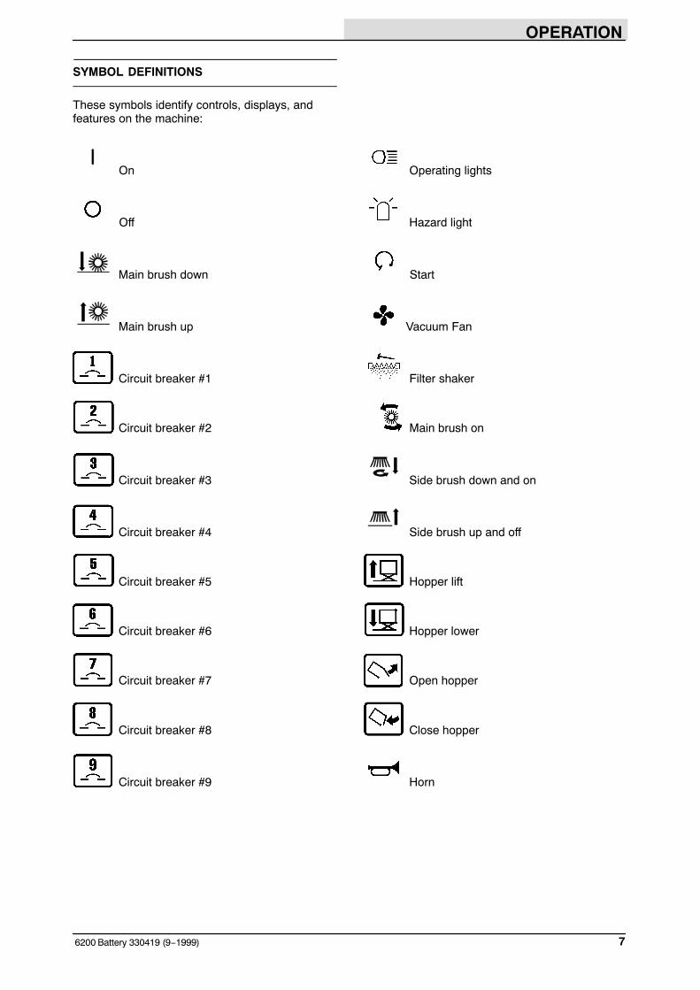
SYMBOL DEFINITIONS
These symbols identify controls, displays, andfeatures on the machine:
On Operating lights
Off Hazard light
Main brush down Start
Main brush up Vacuum Fan
Circuit breaker #1 Filter shaker
Circuit breaker #2 Main brush on
Circuit breaker #3 Side brush down and on
Circuit breaker #4 Side brush up and off
Circuit breaker #5 Hopper lift
Circuit breaker #6 Hopper lower
Circuit breaker #7 Open hopper
Circuit breaker #8 Close hopper
Circuit breaker #9 Horn
OPERATION
6200 Battery 330419 (4−2008)8
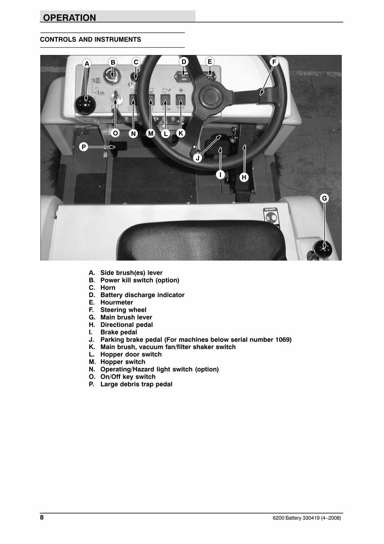
CONTROLS AND INSTRUMENTS
F
I
A B C D E
G
H
P
J
NO M L K
A. Side brush(es) leverB. Power kill switch (option)C. HornD. Battery discharge indicatorE. HourmeterF. Steering wheelG. Main brush leverH. Directional pedalI. Brake pedalJ. Parking brake pedal (For machines below serial number 1069)K. Main brush, vacuum fan/filter shaker switchL. Hopper door switchM. Hopper switchN. Operating/Hazard light switch (option)O. On/Off key switchP. Large debris trap pedal
OPERATION
96200 Battery 330419 (9−1999)
OPERATION OF CONTROLS
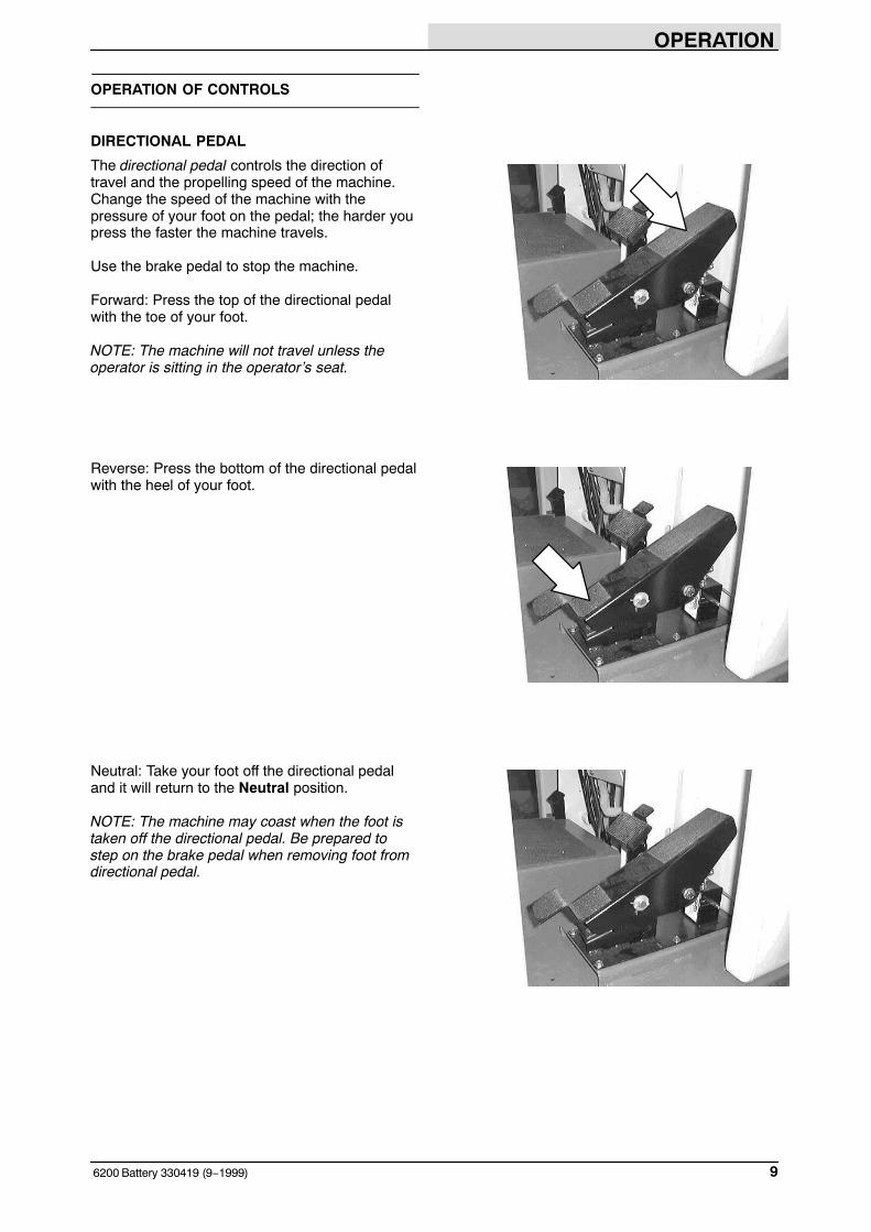
DIRECTIONAL PEDAL
The directional pedal controls the direction oftravel and the propelling speed of the machine.Change the speed of the machine with thepressure of your foot on the pedal; the harder youpress the faster the machine travels.
Use the brake pedal to stop the machine.
Forward: Press the top of the directional pedalwith the toe of your foot.
NOTE: The machine will not travel unless theoperator is sitting in the operator’s seat.
Reverse: Press the bottom of the directional pedalwith the heel of your foot.
Neutral: Take your foot off the directional pedaland it will return to the Neutral position.
NOTE: The machine may coast when the foot istaken off the directional pedal. Be prepared tostep on the brake pedal when removing foot fromdirectional pedal.
OPERATION
6200 Battery 330419 (4−2008)10
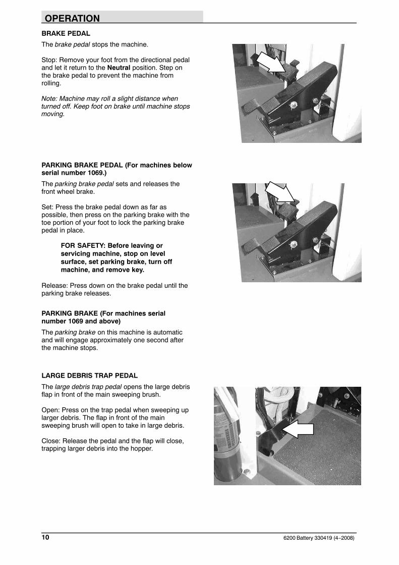
BRAKE PEDAL
The brake pedal stops the machine.
Stop: Remove your foot from the directional pedaland let it return to the Neutral position. Step onthe brake pedal to prevent the machine fromrolling.
Note: Machine may roll a slight distance whenturned off. Keep foot on brake until machine stopsmoving.
PARKING BRAKE PEDAL (For machines belowserial number 1069.)
The parking brake pedal sets and releases thefront wheel brake.
Set: Press the brake pedal down as far aspossible, then press on the parking brake with thetoe portion of your foot to lock the parking brakepedal in place.
FOR SAFETY: Before leaving orservicing machine, stop on levelsurface, set parking brake, turn offmachine, and remove key.
Release: Press down on the brake pedal until theparking brake releases.
PARKING BRAKE (For machines serialnumber 1069 and above)
The parking brake on this machine is automaticand will engage approximately one second afterthe machine stops.
LARGE DEBRIS TRAP PEDAL
The large debris trap pedal opens the large debrisflap in front of the main sweeping brush.
Open: Press on the trap pedal when sweeping uplarger debris. The flap in front of the mainsweeping brush will open to take in large debris.
Close: Release the pedal and the flap will close,trapping larger debris into the hopper.

OPERATION
116200 Battery 330419 (3−2006)
MAIN BRUSH LEVER
The main brush lever controls the position of themain brush.
Main brush down: Pull the lever to the right andback into the Main brush down position.
Main brush up: Push the lever up and to the leftinto the Main brush up position.
MAIN BRUSH/VACUUM FAN AND FILTER SHAKER SWITCH
The main brush/vacuum fan and filter shakerswitch controls the vacuum fan, rotation of themain brush and the VCS Vibrating Comb Shakersystem filter shaker.
Vacuum and main brush on: Press the top of theswitch to the Main brush and vacuum fan onposition.
Vacuum and main brush off: Press the switch tothe middle off position.
Start VCS system filter shaker: Press and holdthe bottom of the switch for eight to ten seconds.
NOTE: Excessive heat in the hopper will causethe Thermo Sentry to shut off the main brush andvacuum fan. If this happens, stop the machine andeliminate the source of heat. Press the mainbrush, vaccum fan and filter shaker switch to themiddle off position, then back to the on position.
POWER KILL SWITCH (OPTION)
The power kill switch halts all power to themachine.
Halt: Push the power kill switch in.
Restart: Turn off the machine power. Turn thepower kill switch to the right to release the switch.Turn on the machine power.

OPERATION
6200 Battery 330419 (1−2000)12
BATTERY DISCHARGE INDICATOR
The battery discharge indicator shows the chargelevel of the batteries. It displays the charge levelwhen the machine is operating.
When the batteries are fully charged, the indicatoron the far right is lit. As the batteries discharge,the indicator will move along the display to the left.Recharge the batteries when the indicator flashes.
NOTE: The reading on the battery dischargeindicator is not accurate when the machine is firstpowered on. Operate the machine a few minutesbefore reading the charge level of the batteries.
NOTE: The battery discharge indicator will notreset from the flashing indicator unless thebatteries have been fully charged.
STEERING WHEEL
The steering wheel controls the machine’sdirection. The machine is very responsive to thesteering wheel movements.
Left: Turn the steering wheel to the left.
Right: Turn the steering wheel to the right.
HOURMETER
The hourmeter records the number of hours themachine has been operated. The hourmeterdisplays the number of hours in tenths of an hour.Use this information to determine machinemaintenance intervals.
OPERATION
136200 Battery 330419 (12−2015)
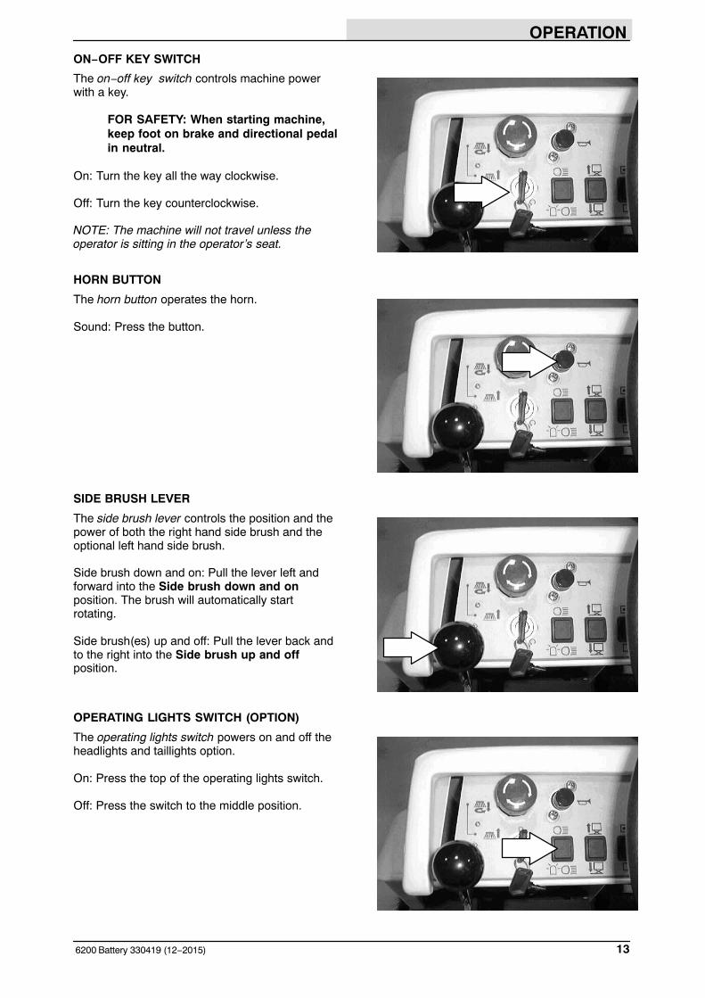
ON−OFF KEY SWITCH
The on−off key switch controls machine powerwith a key.
FOR SAFETY: When starting machine,keep foot on brake and directional pedalin neutral.
On: Turn the key all the way clockwise.
Off: Turn the key counterclockwise.
NOTE: The machine will not travel unless theoperator is sitting in the operator’s seat.
HORN BUTTON
The horn button operates the horn.
Sound: Press the button.
SIDE BRUSH LEVER
The side brush lever controls the position and thepower of both the right hand side brush and theoptional left hand side brush.
Side brush down and on: Pull the lever left andforward into the Side brush down and onposition. The brush will automatically startrotating.
Side brush(es) up and off: Pull the lever back andto the right into the Side brush up and offposition.
OPERATING LIGHTS SWITCH (OPTION)
The operating lights switch powers on and off theheadlights and taillights option.
On: Press the top of the operating lights switch.
Off: Press the switch to the middle position.
OPERATION
6200 Battery 330419 (12−2015)14
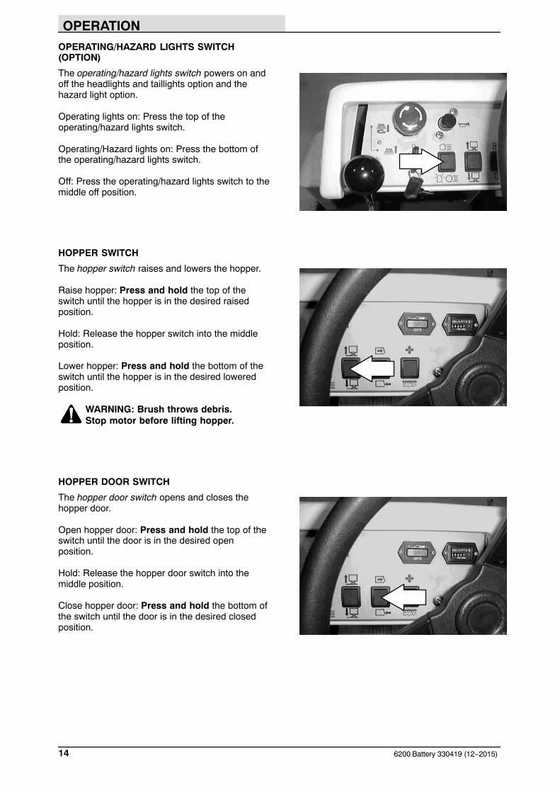
OPERATING/HAZARD LIGHTS SWITCH(OPTION)
The operating/hazard lights switch powers on andoff the headlights and taillights option and thehazard light option.
Operating lights on: Press the top of theoperating/hazard lights switch.
Operating/Hazard lights on: Press the bottom ofthe operating/hazard lights switch.
Off: Press the operating/hazard lights switch to themiddle off position.
HOPPER SWITCH
The hopper switch raises and lowers the hopper.
Raise hopper: Press and hold the top of theswitch until the hopper is in the desired raisedposition.
Hold: Release the hopper switch into the middleposition.
Lower hopper: Press and hold the bottom of theswitch until the hopper is in the desired loweredposition.
WARNING: Brush throws debris. Stop motor before lifting hopper.
HOPPER DOOR SWITCH
The hopper door switch opens and closes thehopper door.
Open hopper door: Press and hold the top of theswitch until the door is in the desired openposition.
Hold: Release the hopper door switch into themiddle position.
Close hopper door: Press and hold the bottom ofthe switch until the door is in the desired closedposition.

OPERATION
156200 Battery 330419 (4−2008)
FUSES
Fuses are one-time protection devices designed tostop the flow of current in the event of a circuitoverload. Never substitute higher value fuses thanspecified.
The fuse is located behind the circuit breakerpanel.
Fuse Rating Circuit Protected
FU-1 80 A Main
CIRCUIT BREAKERS
The circuit breakers are resettable electrical circuitprotection devices. Their design stops the flow ofcurrent in the event of a circuit overload. Once acircuit breaker is tripped, it must be resetmanually. Press the reset button after the breakerhas cooled down. The circuit breakers will notreset until they have had a chance to cool down.
If the overload that caused the circuit breaker totrip is still there, the circuit breaker will continue tostop current flow until the problem is corrected.
Circuit breakers 1 through 9 are located above thefoot pedals in the circuit breaker panel.
The chart lists the circuit breakers and theelectrical components they protect.
Circuit Breaker Rating Circuit Protected
CB-1 15 A Main Power
CB-2 15 A Horn
CB-3 15 A Side Brushes
CB-4 15 A Hopper Door
CB-5 15 A Oper. LightsWarning Lights
CB-6 25 A Hopper Lift Pump
CB-7 25 A Main Brush
CB-8 20 A Sweep Fan Motor
CB-9 (S/N 0001−0xxx)
20 A Vac Wand (Option)
CB-9 (S/N 0xxx−)
25 A Vac Wand (Option)
1 32 4 85 6 7 9

OPERATION
6200 Battery 330419 (9−1999)16
OPERATOR SEAT
The operator seat is a fixed back style.
NOTE: The operator seat has a safety switch thatstops the machine from propelling unless theoperator is sitting in the operator’s seat.
ADJUSTABLE OPERATOR SEAT (OPTION)
The adjustable operator seat is a fixed back stylewith a foward−backward adjustment.
Adjust: Pull the lever in, slide the seat backward orfoward to the desired position, and release thelever.
DELUXE SUSPENSION SEAT (OPTION)
The deluxe suspension seat has four adjustments.The adjustments are for the lumbar support,backrest angle, operator weight adjustment andfront to back adjustment.
The lumbar adjustment knob controls the firmnessof the lumbar support.
Increase firmness:Turn knob clockwise.
Decrease firmness:Turn knob counterclockwise.
The backrest angle knob adjusts the angle of thebackrest.
Increase angle: Turn the angle adjustment knobcounterclockwise.
Decrease angle: Turn the angle adjustment knobclockwise.
OPERATION
176200 Battery 330419 (9−1999)
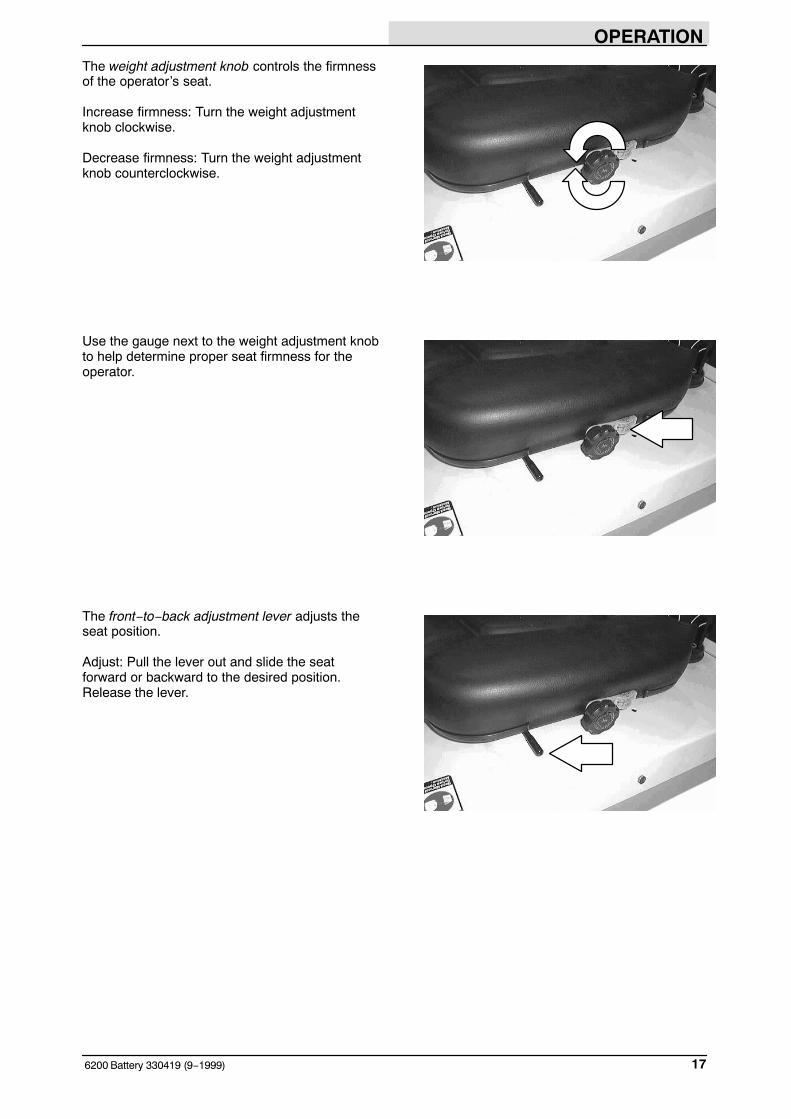
The weight adjustment knob controls the firmnessof the operator’s seat.
Increase firmness: Turn the weight adjustmentknob clockwise.
Decrease firmness: Turn the weight adjustmentknob counterclockwise.
Use the gauge next to the weight adjustment knobto help determine proper seat firmness for theoperator.
The front−to−back adjustment lever adjusts theseat position.
Adjust: Pull the lever out and slide the seatforward or backward to the desired position.Release the lever.
OPERATION
6200 Battery 330419 (9−1999)18
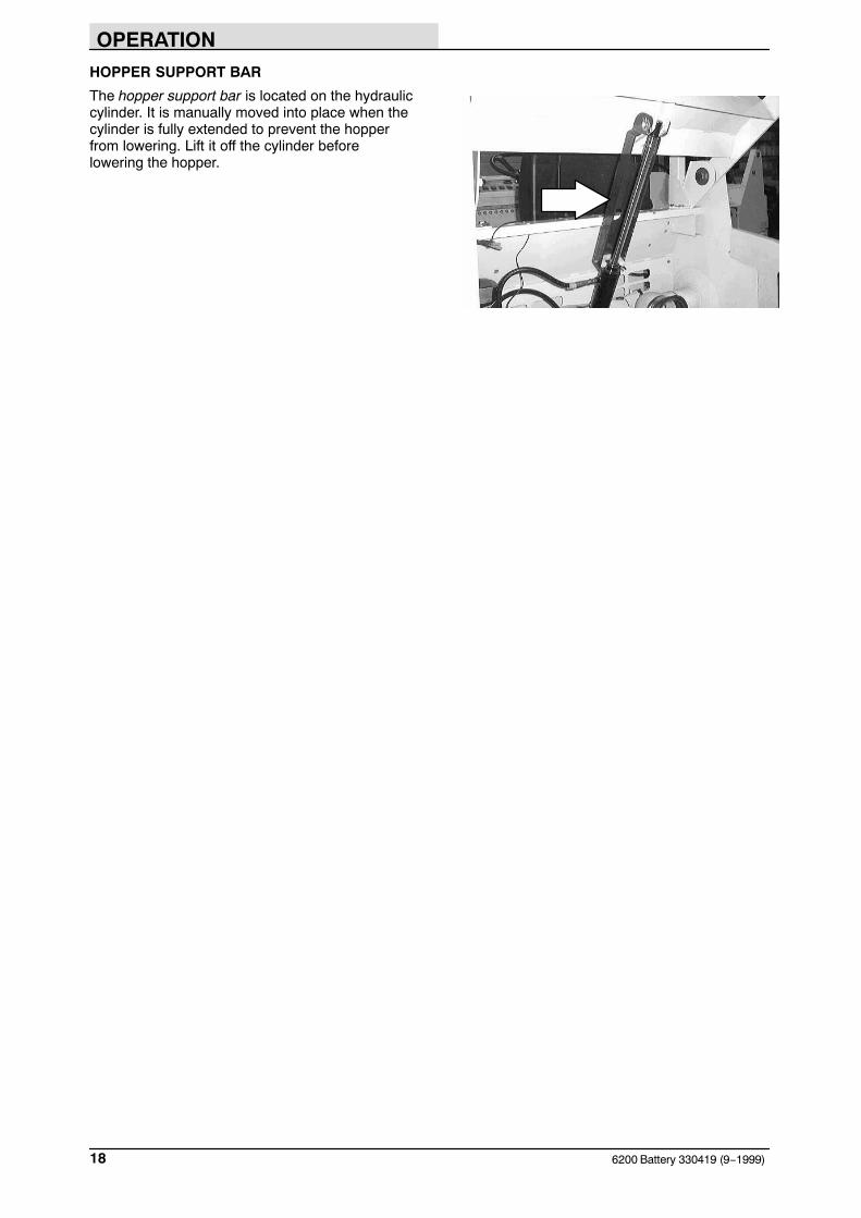
HOPPER SUPPORT BAR
The hopper support bar is located on the hydrauliccylinder. It is manually moved into place when thecylinder is fully extended to prevent the hopperfrom lowering. Lift it off the cylinder beforelowering the hopper.
OPERATION
196200 Battery 330419 (9−2005)
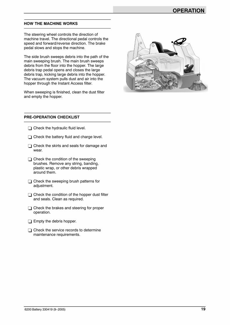
HOW THE MACHINE WORKS
The steering wheel controls the direction ofmachine travel. The directional pedal controls thespeed and forward/reverse direction. The brakepedal slows and stops the machine.
The side brush sweeps debris into the path of themain sweeping brush. The main brush sweepsdebris from the floor into the hopper. The largedebris trap pedal opens and closes the largedebris trap, kicking large debris into the hopper.The vacuum system pulls dust and air into thehopper through the Instant Access filter.
When sweeping is finished, clean the dust filterand empty the hopper.
PRE-OPERATION CHECKLIST
� Check the hydraulic fluid level.
� Check the battery fluid and charge level.
� Check the skirts and seals for damage andwear.
� Check the condition of the sweepingbrushes. Remove any string, banding, plastic wrap, or other debris wrapped around them.
� Check the sweeping brush patterns foradjustment.
� Check the condition of the hopper dust filterand seals. Clean as required.
� Check the brakes and steering for properoperation.
� Empty the debris hopper.
� Check the service records to determinemaintenance requirements.
OPERATION
6200 Battery 330419 (9−1999)20
STARTING THE MACHINE
1. Sit in the operator’s seat and engage thebrakes with the directional pedal in neutral.
FOR SAFETY: When starting machine,keep foot on brake and directional pedalin neutral.
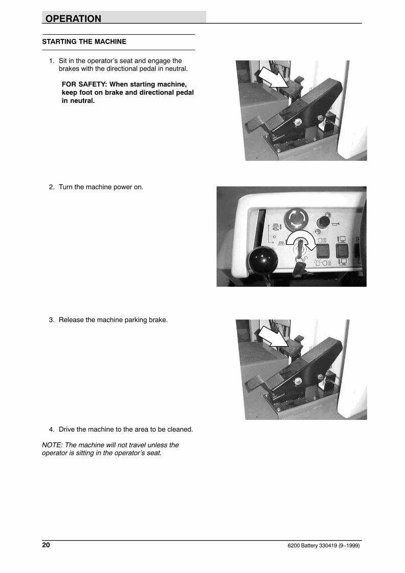
2. Turn the machine power on.
3. Release the machine parking brake.
4. Drive the machine to the area to be cleaned.
NOTE: The machine will not travel unless theoperator is sitting in the operator’s seat.
OPERATION
216200 Battery 330419 (9−2001)
SWEEPING AND BRUSH INFORMATION
Pick up oversized debris before sweeping. Flattenor remove bulky cartons from aisles beforesweeping. Pick up pieces of wire, twine, string,etc., which could become entangled in the brushor brush plugs.
Plan the sweeping in advance. Try to arrange longruns with minimum stopping and starting. Do anentire floor or section at one time. Drive thestraightest path possible. Avoid bumping intoposts or scraping the sides of the machine.Overlap the brush paths.
Avoid turning the steering wheel too sharply whenthe machine is in motion. The machine is veryresponsive to the movement of the steering wheel.Avoid sudden turns, except in emergencies.
For best results, use the correct brush type foryour sweeping application. The following arerecommendations for main sweeping and sidebrush applications.
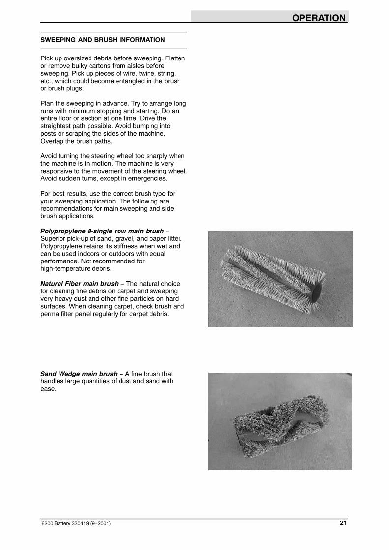
Polypropylene 8-single row main brush −Superior pick-up of sand, gravel, and paper litter.Polypropylene retains its stiffness when wet andcan be used indoors or outdoors with equalperformance. Not recommended forhigh-temperature debris.
Natural Fiber main brush − The natural choicefor cleaning fine debris on carpet and sweepingvery heavy dust and other fine particles on hardsurfaces. When cleaning carpet, check brush andperma filter panel regularly for carpet debris.
Sand Wedge main brush − A fine brush thathandles large quantities of dust and sand withease.
OPERATION
6200 Battery 330419 (9−2002)22
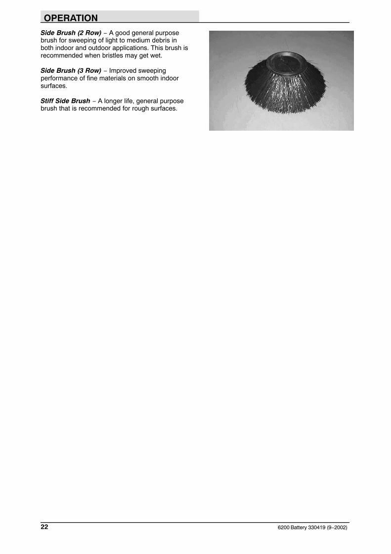
Side Brush (2 Row) − A good general purposebrush for sweeping of light to medium debris inboth indoor and outdoor applications. This brush isrecommended when bristles may get wet.
Side Brush (3 Row) − Improved sweepingperformance of fine materials on smooth indoorsurfaces.
Stiff Side Brush − A longer life, general purposebrush that is recommended for rough surfaces.
OPERATION
236200 Battery 330419 (1−2000)
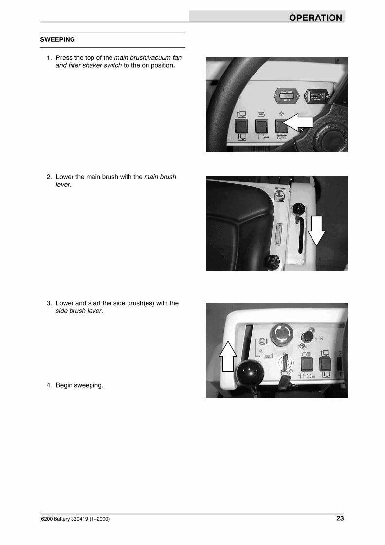
SWEEPING
1. Press the top of the main brush/vacuum fanand filter shaker switch to the on position.
2. Lower the main brush with the main brushlever.
3. Lower and start the side brush(es) with theside brush lever.
4. Begin sweeping.

OPERATION
6200 Battery 330419 (9−1999)24
5. Press down on the large debris trap pedalwhen sweeping large debris.
6. Release the pedal, and the flap will lowerover the debris.
7. The flap will trap large debris back into thehopper.
OPERATION
256200 Battery 330419 (1−2000)
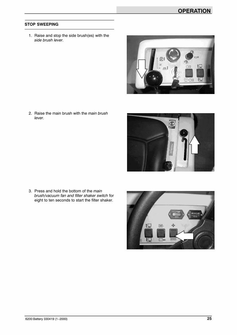
STOP SWEEPING
1. Raise and stop the side brush(es) with theside brush lever.
2. Raise the main brush with the main brushlever.
3. Press and hold the bottom of the mainbrush/vacuum fan and filter shaker switch foreight to ten seconds to start the filter shaker.
OPERATION
6200 Battery 330419 (1−2000)26
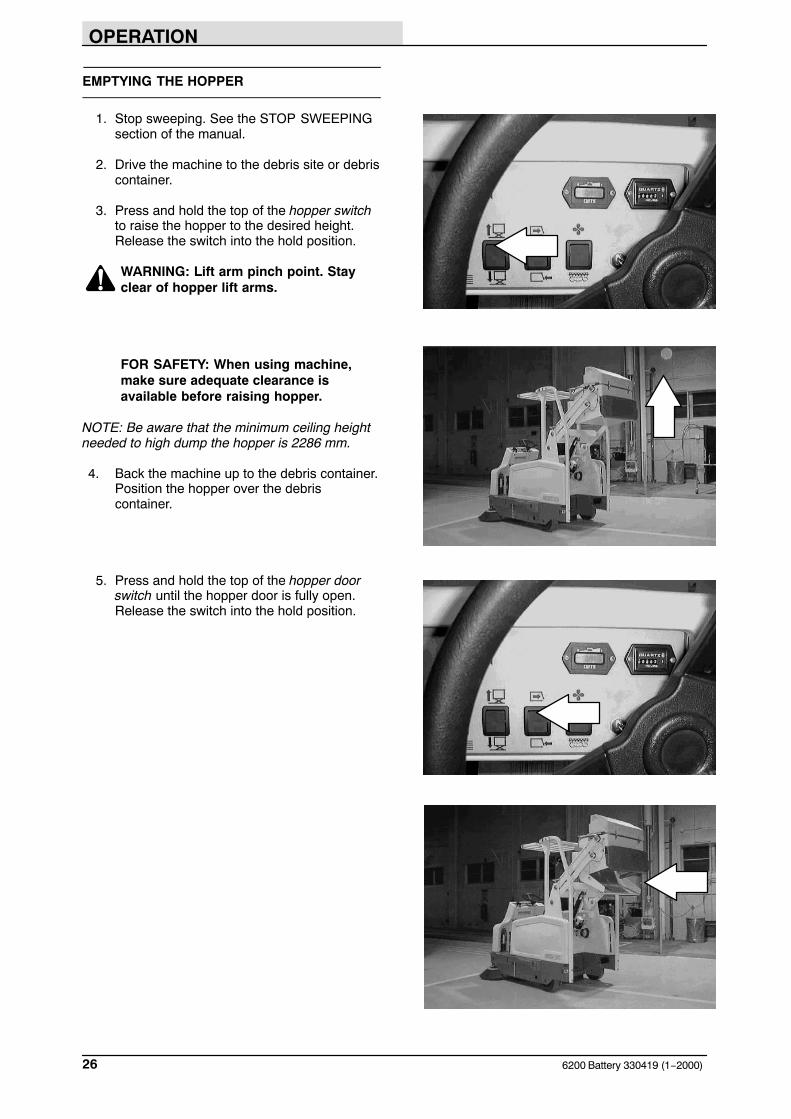
EMPTYING THE HOPPER
1. Stop sweeping. See the STOP SWEEPINGsection of the manual.
2. Drive the machine to the debris site or debriscontainer.
3. Press and hold the top of the hopper switchto raise the hopper to the desired height.Release the switch into the hold position.
WARNING: Lift arm pinch point. Stayclear of hopper lift arms.
FOR SAFETY: When using machine,make sure adequate clearance isavailable before raising hopper.
NOTE: Be aware that the minimum ceiling heightneeded to high dump the hopper is 2286 mm.
4. Back the machine up to the debris container.Position the hopper over the debriscontainer.
5. Press and hold the top of the hopper doorswitch until the hopper door is fully open.Release the switch into the hold position.

OPERATION
276200 Battery 330419 (1−2000)
6. Press and hold the bottom of the hopperdoor switch until the door is fully closed.
7. Press and hold the bottom of the hopperswitch until the hopper is fully lowered.
WARNING: Lift arm pinch point. Stayclear of hopper lift arms.
OPERATION
6200 Battery 330419 (9−1999)28
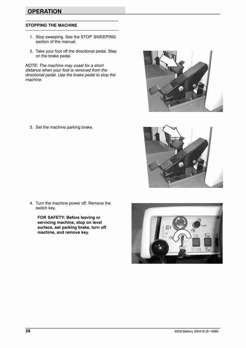
STOPPING THE MACHINE
1. Stop sweeping. See the STOP SWEEPINGsection of the manual.
2. Take your foot off the directional pedal. Stepon the brake pedal.
NOTE: The machine may coast for a shortdistance when your foot is removed from thedirectional pedal. Use the brake pedal to stop themachine.
3. Set the machine parking brake.
4. Turn the machine power off. Remove theswitch key.
FOR SAFETY: Before leaving orservicing machine, stop on levelsurface, set parking brake, turn offmachine, and remove key.
OPERATION
296200 Battery 330419 (9−2005)
POST-OPERATION CHECKLIST
Check this list of items after you have finishedsweeping:
� Check the hydraulic fluid level.
� Check the battery fluid and charge level.
� Check the skirts and seals for damage andwear.
� Check the condition of the sweepingbrushes. Remove any string, banding, plasticwrap, or other debris wrapped around them.
� Check the sweeping brush patterns foradjustment.
� Check the condition of the hopper dust filterand seals. Clean as required.
� Check the brakes and steering for properoperation.
� Empty the debris hopper.
� Check the service records to determinemaintenance requirements.
OPERATION
6200 Battery 330419 (1−2000)30
ENGAGING HOPPER SUPPORT BAR
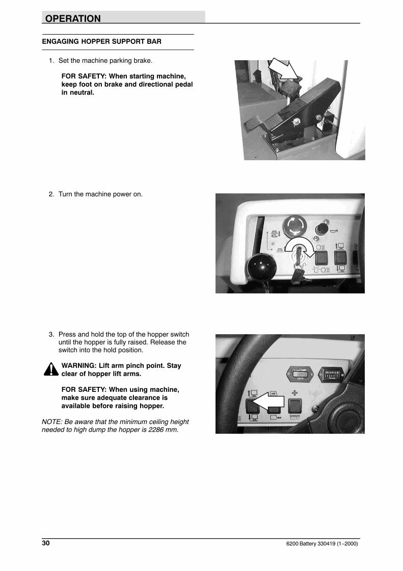
1. Set the machine parking brake.
FOR SAFETY: When starting machine,keep foot on brake and directional pedalin neutral.
2. Turn the machine power on.
3. Press and hold the top of the hopper switchuntil the hopper is fully raised. Release theswitch into the hold position.
WARNING: Lift arm pinch point. Stayclear of hopper lift arms.
FOR SAFETY: When using machine,make sure adequate clearance isavailable before raising hopper.
NOTE: Be aware that the minimum ceiling heightneeded to high dump the hopper is 2286 mm.
OPERATION
316200 Battery 330419 (1−2000)
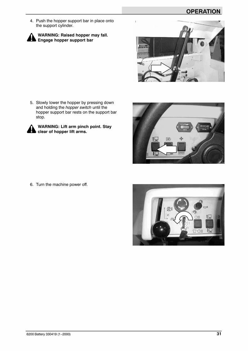
4. Push the hopper support bar in place ontothe support cylinder.
WARNING: Raised hopper may fall.Engage hopper support bar
5. Slowly lower the hopper by pressing downand holding the hopper switch until thehopper support bar rests on the support barstop.
WARNING: Lift arm pinch point. Stayclear of hopper lift arms.
6. Turn the machine power off.
OPERATION
6200 Battery 330419 (1−2000)32
DISENGAGING HOPPER SUPPORT BAR
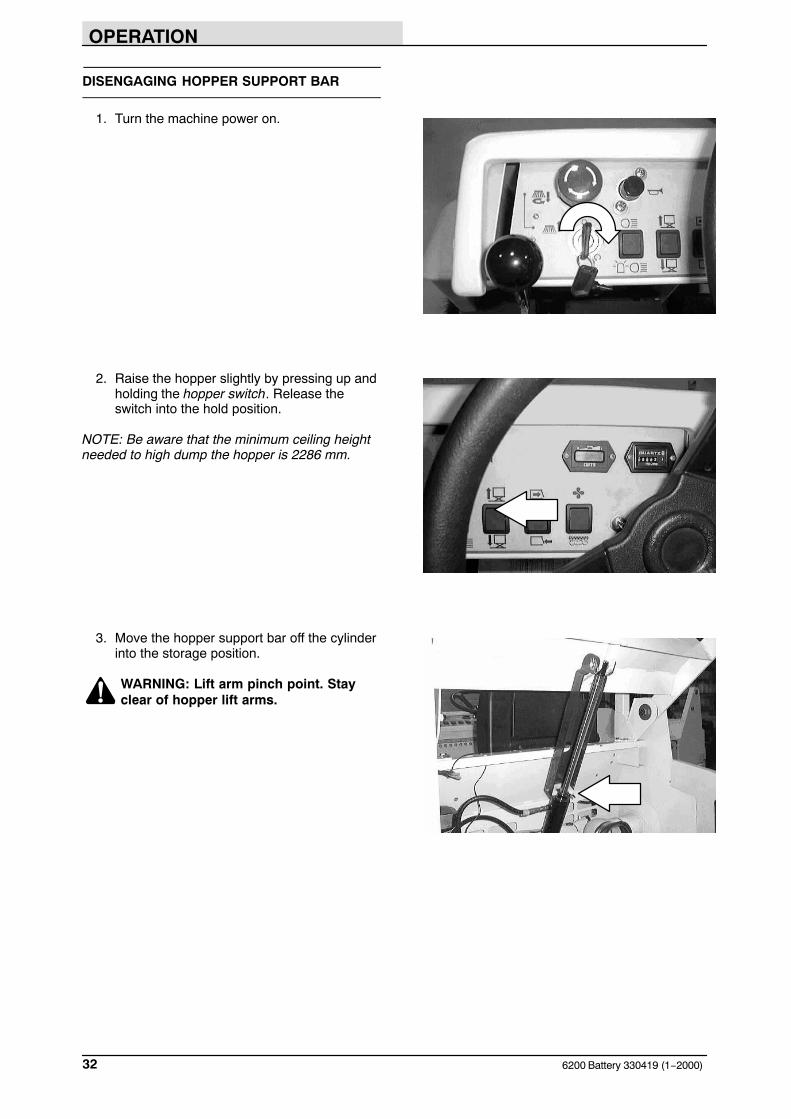
1. Turn the machine power on.
2. Raise the hopper slightly by pressing up andholding the hopper switch. Release theswitch into the hold position.
NOTE: Be aware that the minimum ceiling heightneeded to high dump the hopper is 2286 mm.
3. Move the hopper support bar off the cylinderinto the storage position.
WARNING: Lift arm pinch point. Stayclear of hopper lift arms.
OPERATION
336200 Battery 330419 (1−2000)
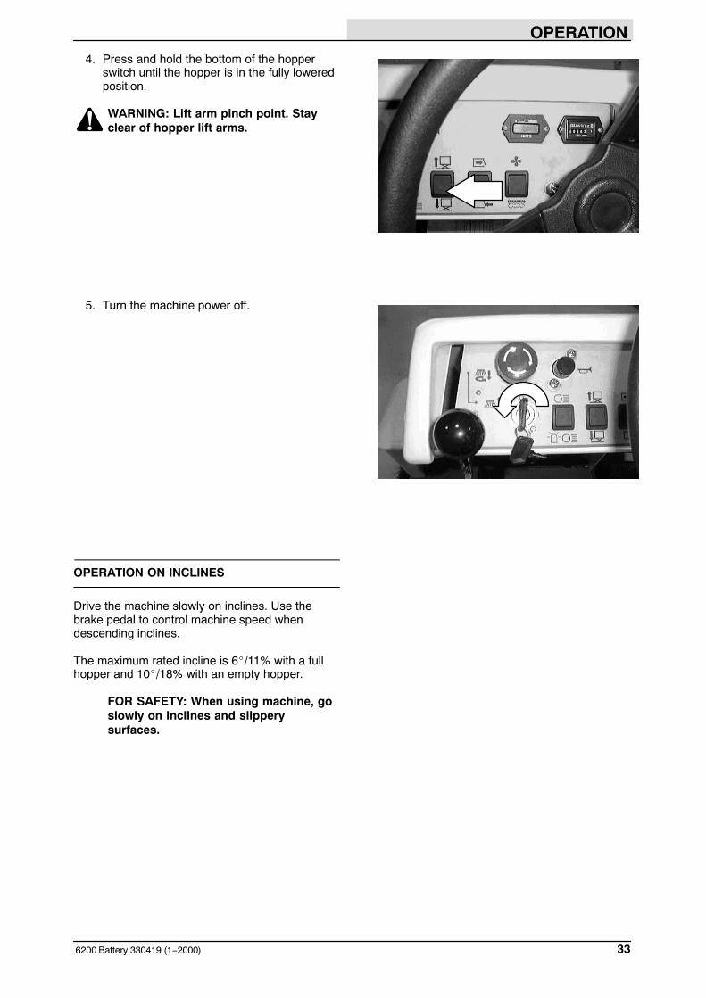
4. Press and hold the bottom of the hopperswitch until the hopper is in the fully loweredposition.
WARNING: Lift arm pinch point. Stayclear of hopper lift arms.
5. Turn the machine power off.
OPERATION ON INCLINES
Drive the machine slowly on inclines. Use thebrake pedal to control machine speed whendescending inclines.
The maximum rated incline is 6�/11% with a fullhopper and 10�/18% with an empty hopper.
FOR SAFETY: When using machine, goslowly on inclines and slipperysurfaces.
OPERATION
6200 Battery 330419 (9−1999)34
OPTIONS
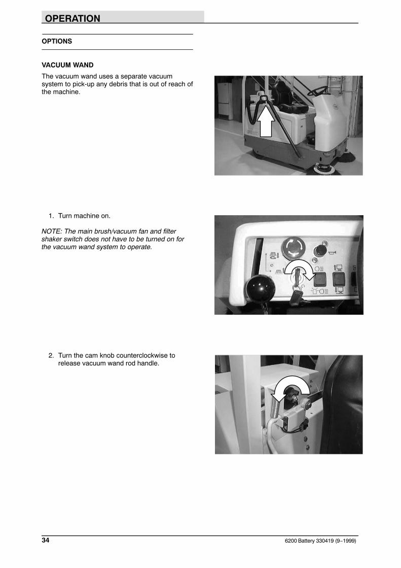
VACUUM WAND
The vacuum wand uses a separate vacuumsystem to pick-up any debris that is out of reach ofthe machine.
1. Turn machine on.
NOTE: The main brush/vacuum fan and filtershaker switch does not have to be turned on forthe vacuum wand system to operate.
2. Turn the cam knob counterclockwise torelease vacuum wand rod handle.

OPERATION
356200 Battery 330419 (9−1999)
3. Wand On: Raise the vacuum wand from thestorage position. The vacuum will turn onautomatically.
4. Wand Off: Return the vacuum wand back tostorage position and the vacuum will turn off.
5. Turn the cam knob clockwise to securevacuum wand rod handle.
6. Replace full vacuum bags whenever wandbegins to lose power or when bags are full.
OPERATION
6200 Battery 330419 (9−1999)36
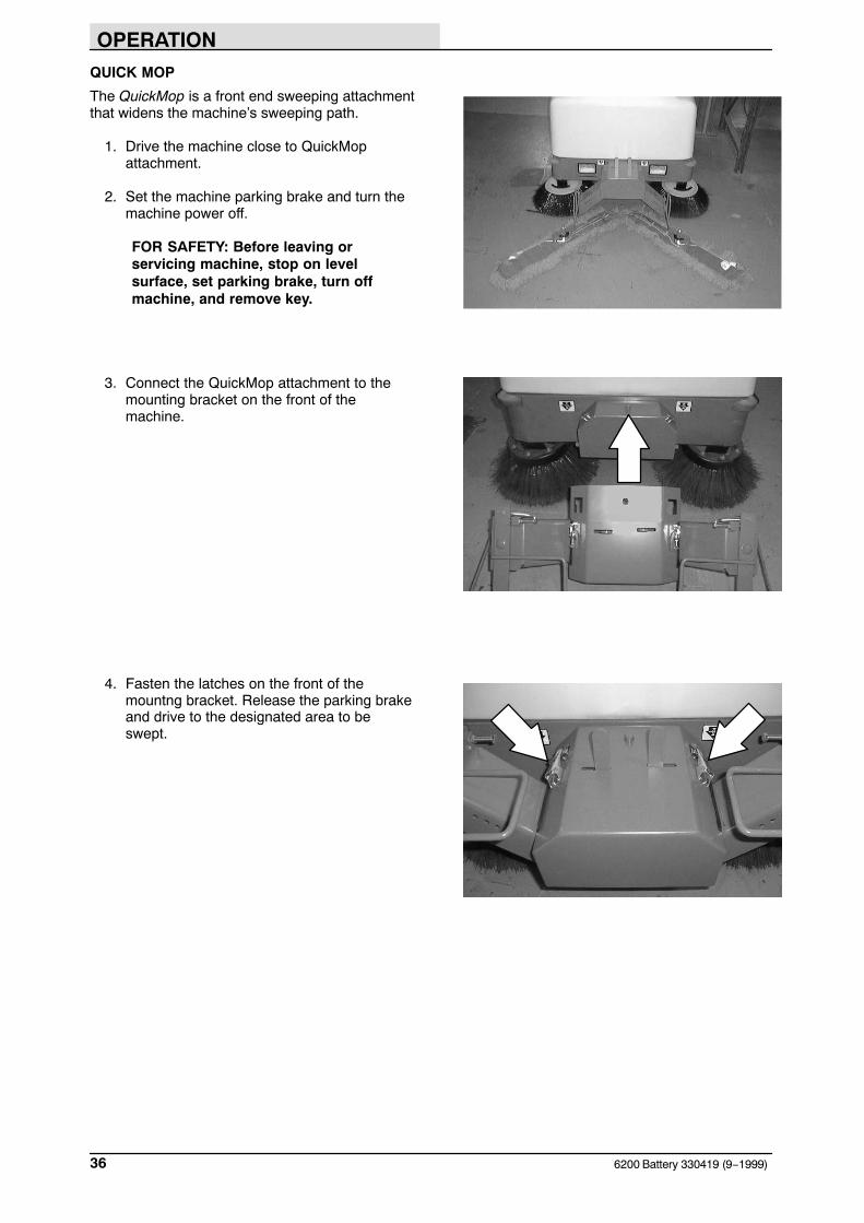
QUICK MOP
The QuickMop is a front end sweeping attachmentthat widens the machine’s sweeping path.
1. Drive the machine close to QuickMopattachment.
2. Set the machine parking brake and turn themachine power off.
FOR SAFETY: Before leaving orservicing machine, stop on levelsurface, set parking brake, turn offmachine, and remove key.
3. Connect the QuickMop attachment to themounting bracket on the front of themachine.
4. Fasten the latches on the front of themountng bracket. Release the parking brakeand drive to the designated area to beswept.
OPERATION
376200 Battery 330419 (9−1999)
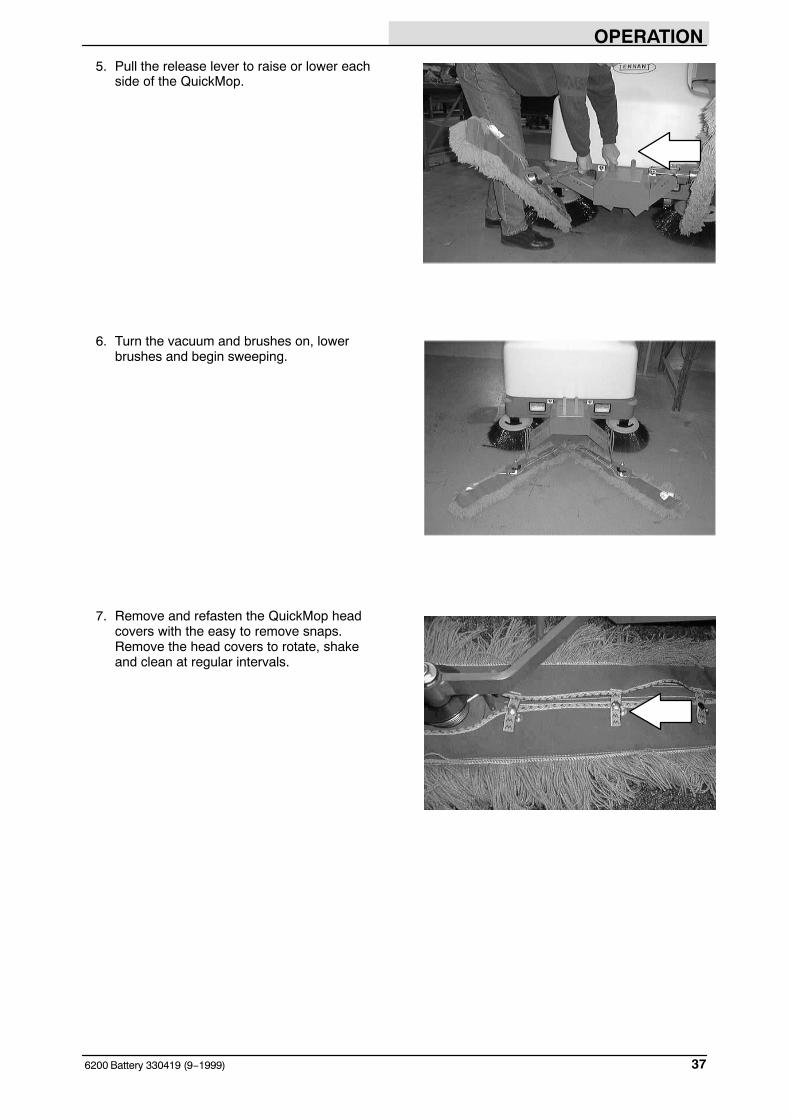
5. Pull the release lever to raise or lower eachside of the QuickMop.
6. Turn the vacuum and brushes on, lowerbrushes and begin sweeping.
7. Remove and refasten the QuickMop headcovers with the easy to remove snaps.Remove the head covers to rotate, shakeand clean at regular intervals.
OPERATION
6200 Battery 330419 (9−1999)38
ROLLOUT BATTERY
The rollout battery allows the operator a quick andeasy way to remove and replace the batteriesfrom the machine.
1. Drive the machine to a flat, dry surface.
2. Turn the machine off and set the parkingbrake.
FOR SAFETY: Before leaving orservicing machine, stop on levelsurface, set parking brake, turn offmachine, and remove key.
3. Lift the operator seat to access the batteries.The support arm automatically engageswhen the seat is lifted all the way up.
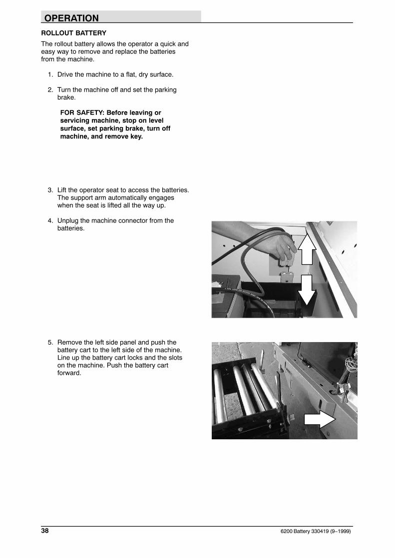
4. Unplug the machine connector from thebatteries.
5. Remove the left side panel and push thebattery cart to the left side of the machine.Line up the battery cart locks and the slotson the machine. Push the battery cartforward.
OPERATION
396200 Battery 330419 (9−1999)
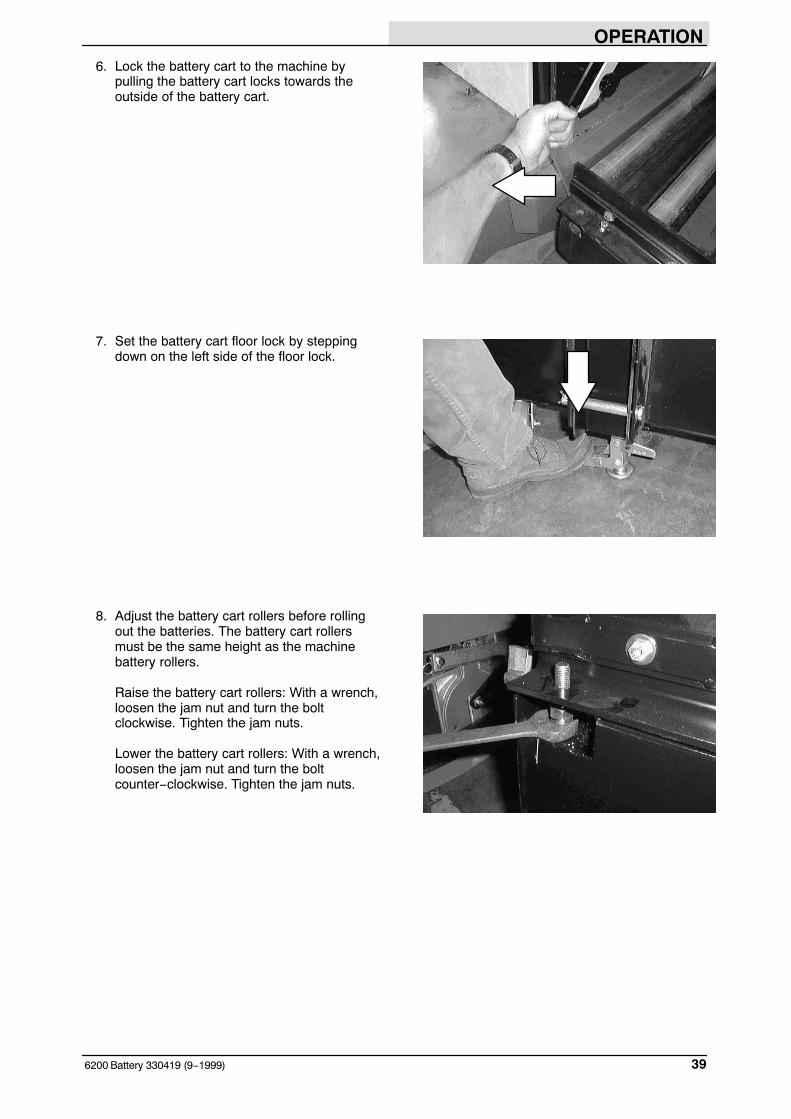
6. Lock the battery cart to the machine bypulling the battery cart locks towards theoutside of the battery cart.
7. Set the battery cart floor lock by steppingdown on the left side of the floor lock.
8. Adjust the battery cart rollers before rollingout the batteries. The battery cart rollersmust be the same height as the machinebattery rollers.
Raise the battery cart rollers: With a wrench,loosen the jam nut and turn the boltclockwise. Tighten the jam nuts.
Lower the battery cart rollers: With a wrench,loosen the jam nut and turn the boltcounter−clockwise. Tighten the jam nuts.

OPERATION
6200 Battery 330419 (9−1999)40
9. Turn the knob on the machine’s battery stoparm counterclockwise until it stops turning.
10. Raise the machine’s battery stop arm all theway to the horizontal position.
11. Raise the cart’s battery stop bar by pushingdown on the handle.

OPERATION
416200 Battery 330419 (9−1999)
12. Grab the battery case slot and pull thebattery case onto the battery cart.
13. Lower the cart’s battery stop bar by pullingup on the handle. This will keep the batteriesfrom rolling off the cart when moving.
OPERATION
6200 Battery 330419 (9−1999)42
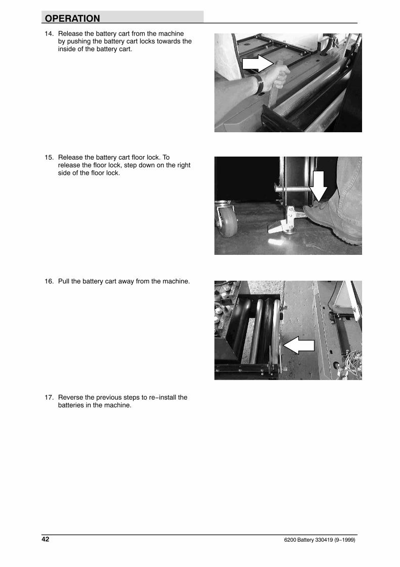
14. Release the battery cart from the machineby pushing the battery cart locks towards theinside of the battery cart.
15. Release the battery cart floor lock. Torelease the floor lock, step down on the rightside of the floor lock.
16. Pull the battery cart away from the machine.
17. Reverse the previous steps to re−install thebatteries in the machine.
OPERATION
436200 Battery 330419 (9−1999)
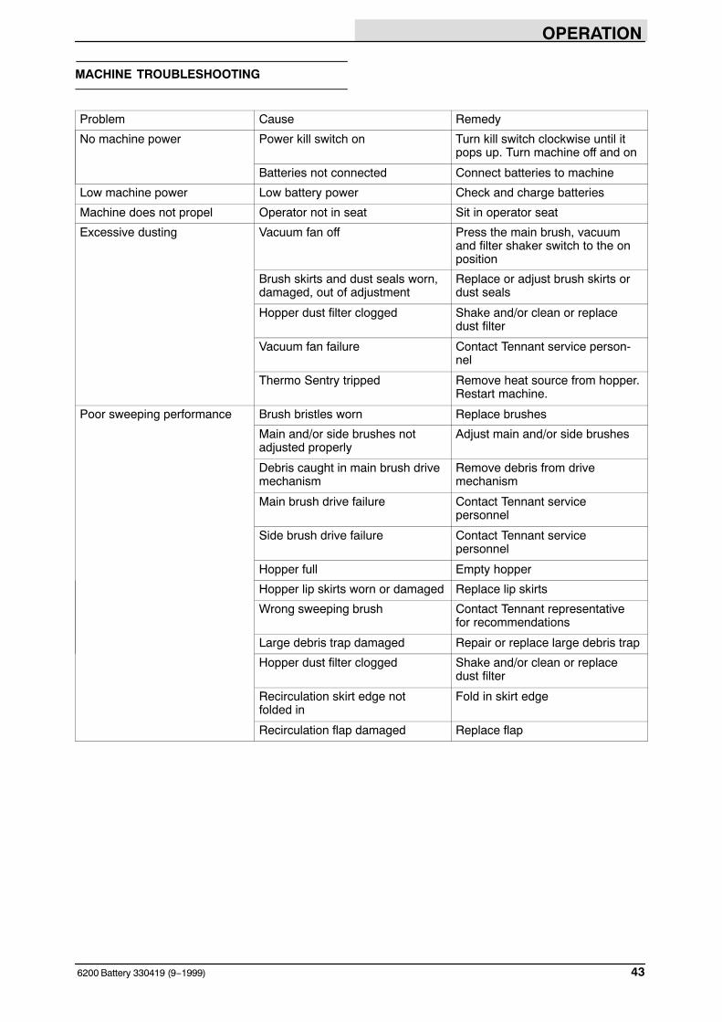
MACHINE TROUBLESHOOTING
Problem Cause Remedy
No machine power Power kill switch on Turn kill switch clockwise until itpops up. Turn machine off and on
Batteries not connected Connect batteries to machine
Low machine power Low battery power Check and charge batteries
Machine does not propel Operator not in seat Sit in operator seat
Excessive dusting Vacuum fan off Press the main brush, vacuumand filter shaker switch to the onposition
Brush skirts and dust seals worn,damaged, out of adjustment
Replace or adjust brush skirts ordust seals
Hopper dust filter clogged Shake and/or clean or replacedust filter
Vacuum fan failure Contact Tennant service person-nel
Thermo Sentry tripped Remove heat source from hopper.Restart machine.
Poor sweeping performance Brush bristles worn Replace brushes
Main and/or side brushes notadjusted properly
Adjust main and/or side brushes
Debris caught in main brush drivemechanism
Remove debris from drivemechanism
Main brush drive failure Contact Tennant servicepersonnel
Side brush drive failure Contact Tennant servicepersonnel
Hopper full Empty hopper
Hopper lip skirts worn or damaged Replace lip skirts
Wrong sweeping brush Contact Tennant representativefor recommendations
Large debris trap damaged Repair or replace large debris trap
Hopper dust filter clogged Shake and/or clean or replacedust filter
Recirculation skirt edge not folded in
Fold in skirt edge
Recirculation flap damaged Replace flap

MAINTENANCE
6200 Battery 330419 (9−2003)44
MAINTENANCE
1 2 36
2
13
12
6 11 10 9 14
14
8
6
7
54
16 15
MAINTENANCE CHART
NOTE: Check procedures indicated (�) after the first 50 hours of operation.
Interval Key Description ProcedureLubricant/
Fluid
No. ofServicePoints
Daily 2 Brush compartment skirts Check for damage, wear andadjustment
− 5
14 Side skirts Check for damage, wear andadjustment
− 2
10 Main brush Check for damage, wear andadjustment
− 1
− 1
8 Side brush(es) Check for damage or wear − 1
Check brush pattern − 1
12 Hopper dust filter Shake − 1
50 Hours 10 Main brush Rotate end-for-end − 1
− QuickMop broom (Option) Rotate or wash sweep heads − 2
3 Batteries Check electrolyte level DW 6 (3)
− Vacuum wand bag (Option) Check or change vacuum bag − 1
− Vacuum wand fan (Option) Check for damage or wear − 1

MAINTENANCE
456200 Battery 330419 (2−2010)
Interval Key Description ProcedureLubricant/
Fluid
No. ofServicePoints
100 Hours 12 Hopper dust filter Change for damage, clean orreplace
− 1
13 Hydraulic reservoir Check fluid level HYDO 1
6 Tires Check for damage − 3
1 Hopper seals Check for damage or wear − 6
1 Hopper filter seals Check for damage or wear − 2
12 Vacuum seal Check for damage or wear − 1
2 Large debris trap skirt Check for damage or wear − 1
7 Steering castor pivotbearing
Lubricate and check for wear SPL 1
11 Vacuum fan belt Check tension and wear − 1
9 Main brush belt Check for wear − 1
200 Hours 5 Brakes Check and adjust travel − 1
4 Steering gear chain Lubricate EO 1
8 Side brush(es) guard Check for damage or wear − 1 (2)
3 Battery terminals andcables
�Check and clean − 12
800 Hours 13 Hydraulic hoses Check for wear and damage − 2
7 Propelling motor Check carbon brushes − 1
6 Rear wheels �Check rear wheel axle torque − 1
15 Main brush motor Check carbon brushes − 1
16 Vacuum fan motor Check carbon brushes − 1
2400Hours
13 Hydraulic fluid reservoir * Change hydraulic fluid HYDO 1
NOTE: Change the hydraulic fluid, filter, and suction strainer, indicated (*), after every 800 hours formachines NOT originally equipped with TennantTrue premium hydraulic fluid. (See Hydraulics section).
LUBRICANT/FLUIDDW Distilled water. . . .EO SAE 30 Engine oil. . . .HYDO TennantTrue premium hydraulic fluid or equivalent.SPL Special lubricant, Lubriplate EMB grease (TENNANT part no. 01433−1). . .
NOTE: More frequent intervals may be required in extremely dusty conditions.

MAINTENANCE
6200 Battery 330419 (9−1999)46
LUBRICATION
STEERING GEAR CHAIN
The steering chain turns the front wheel as thesteering wheel is turned to steer the machine.Lubricate the steering chain with SAE 30−weightengine oil and check chain tension every 200hours of operation.
STEERING CASTOR PIVOT BEARING
The steering castor bearing is located under thefloorplate. Remove the floorplate, and lubricate thebearing with Lubriplate EMB grease (TENNANTpart no 01433−1) every 100 hours.
MAINTENANCE
476200 Battery 330419 (2−2010)
HYDRAULICS
HYDRAULIC FLUID RESERVOIR
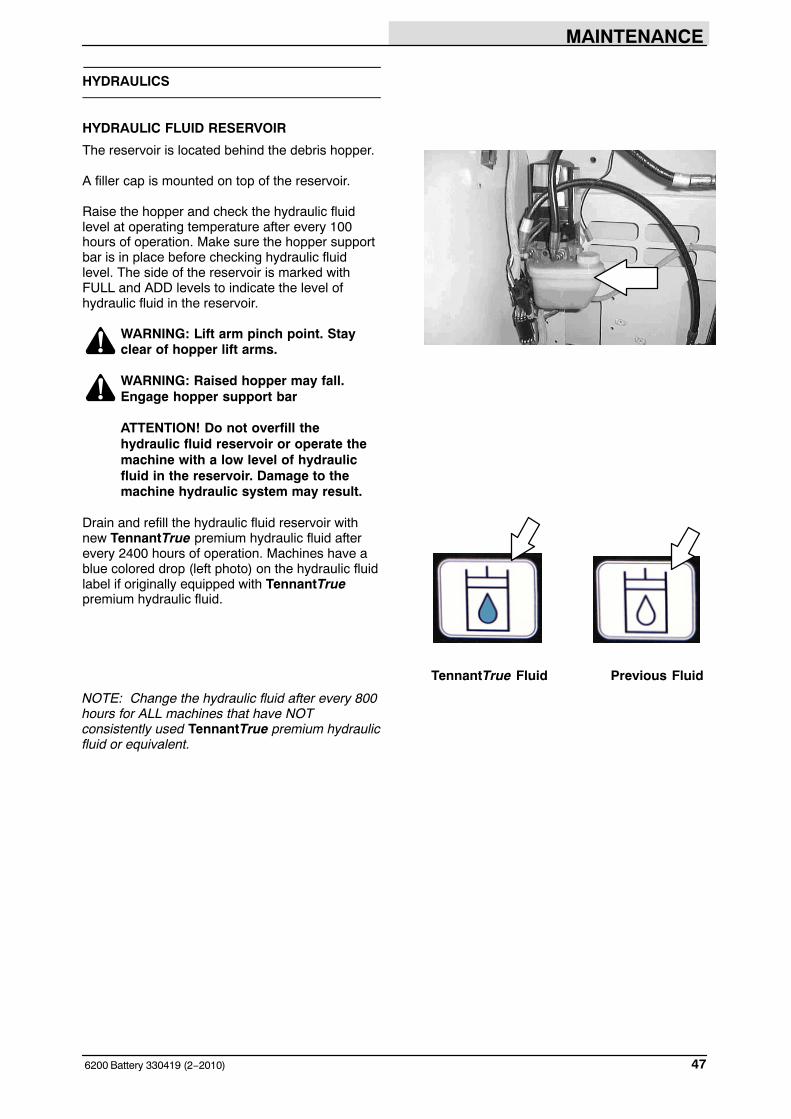
The reservoir is located behind the debris hopper.
A filler cap is mounted on top of the reservoir.
Raise the hopper and check the hydraulic fluidlevel at operating temperature after every 100hours of operation. Make sure the hopper supportbar is in place before checking hydraulic fluidlevel. The side of the reservoir is marked withFULL and ADD levels to indicate the level ofhydraulic fluid in the reservoir.
WARNING: Lift arm pinch point. Stayclear of hopper lift arms.
WARNING: Raised hopper may fall.Engage hopper support bar
ATTENTION! Do not overfill thehydraulic fluid reservoir or operate themachine with a low level of hydraulicfluid in the reservoir. Damage to themachine hydraulic system may result.
Drain and refill the hydraulic fluid reservoir withnew TennantTrue premium hydraulic fluid afterevery 2400 hours of operation. Machines have ablue colored drop (left photo) on the hydraulic fluidlabel if originally equipped with TennantTruepremium hydraulic fluid.
TennantTrue Fluid Previous Fluid
NOTE: Change the hydraulic fluid after every 800hours for ALL machines that have NOTconsistently used TennantTrue premium hydraulicfluid or equivalent.

MAINTENANCE
6200 Battery 330419 (9−99)48
HYDRAULIC FLUID
The quality and condition of the hydraulic fluid playa very important role in how well the machineoperates. Tennant’s hydraulic fluid is speciallyselected to meet the needs of Tennant machines.
Tennant’s hydraulic fluid provide a longer life forthe hydraulic components.
TennantTrue premium hydraulic fluid (Extended Life)
Partnumber
Ambienttemperature
ISOGrade
Ca-pacity
1057707 below 7� C (45� F) 32 3.8 L(1 gal)
1057708 below 7� C (45� F) 32 19 L (5 gal)
If a locally available hydraulic fluid is used, makesure the specifications match Tennant hydraulicfluid specifications. Using substitute fluids cancause premature failure of hydraulic components.
ATTENTION! Hydraulic componentsdepend on system hydraulic fluid forinternal lubrication. Malfunctions,accelerated wear, and damage will resultif dirt or other contaminants enter thehydraulic system.
HYDRAULIC HOSES
Check the hydraulic hoses after every 800 hoursof operation for wear or damage.
Fluid escaping at high pressure from a very smallhole can be almost invisible, and can causeserious injuries.
See a doctor at once if injury results fromescaping hydraulic fluid. Serious infection orreaction can develop if proper medical treatment isnot given immediately.
FOR SAFETY: When servicing machine,use cardboard to locate leakinghydraulic fluid under pressure.
If you discover a fluid leak, contact your mechanicor supervisor.
00002

MAINTENANCE
496200 Battery 330419 (4−2015)
BATTERIES
FOR SAFETY: Before leaving orservicing machine, stop on levelsurface, set parking brake, turn offmachine, and remove key.
The lifetime of the batteries depends on theirproper maintenance. To get the most life from thebatteries;
− Do not charge the batteries more than oncea day and only after running the machine fora minimum of 15 minutes.
− Do not leave the batteries partiallydischarged for long period of time.
− Only charge the batteries in a well-ventilatedarea to prevent gas build up. Chargebatteries in areas with ambient temperatures27�C (80�F) or less.
− Allow the charger to complete charging thebatteries before re-using the machine.
− Maintain the proper electrolyte levels offlooded (wet) batteries by checking levelsweekly.
CHECKING THE ELECTROLYTE LEVEL
The flooded (wet) lead−acid batteries requireroutine maintenance as described below. Checkthe battery electrolyte level weekly.
NOTE: Do Not check the electrolyte level if themachine is equipped with the battery wateringsystem. Proceed to the BATTERY WATERINGSYSTEM (OPTION).
FOR SAFETY: When servicing machine,keep all metal objects off batteries.Avoid contact with battery acid.
The level should be slightly above the batteryplates as shown before charging. Add distilledwater if low. DO NOT OVERFILL. The electrolytewill expand and may overflow when charging.After charging, distilled water can be added up toabout 3 mm (0.12 in) below the sight tubes.
NOTE: Make sure the battery caps are in placewhile charging. There may be a sulfur smell aftercharging batteries. This is normal.
08247
Before Charging After Charging
MAINTENANCE
6200 Battery 330419 (4−2015)50
MAINTENANCE−FREE BATTERIES
Maintenance−free batteries do not requirewatering. Cleaning and other routine maintenanceis still required.
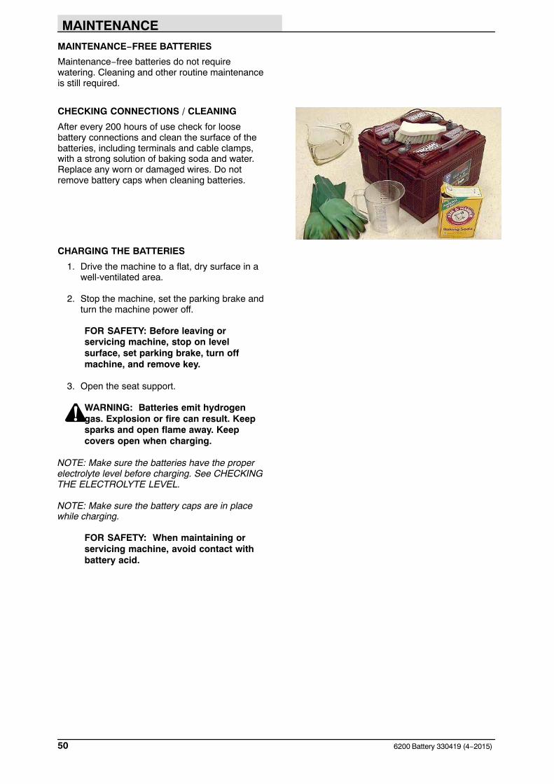
CHECKING CONNECTIONS / CLEANING
After every 200 hours of use check for loosebattery connections and clean the surface of thebatteries, including terminals and cable clamps,with a strong solution of baking soda and water.Replace any worn or damaged wires. Do notremove battery caps when cleaning batteries.
CHARGING THE BATTERIES
1. Drive the machine to a flat, dry surface in awell-ventilated area.
2. Stop the machine, set the parking brake andturn the machine power off.
FOR SAFETY: Before leaving orservicing machine, stop on levelsurface, set parking brake, turn offmachine, and remove key.
3. Open the seat support.
WARNING: Batteries emit hydrogengas. Explosion or fire can result. Keepsparks and open flame away. Keepcovers open when charging.
NOTE: Make sure the batteries have the properelectrolyte level before charging. See CHECKINGTHE ELECTROLYTE LEVEL.
NOTE: Make sure the battery caps are in placewhile charging.
FOR SAFETY: When maintaining orservicing machine, avoid contact withbattery acid.
MAINTENANCE
516200 Battery 330419 (12−2000)
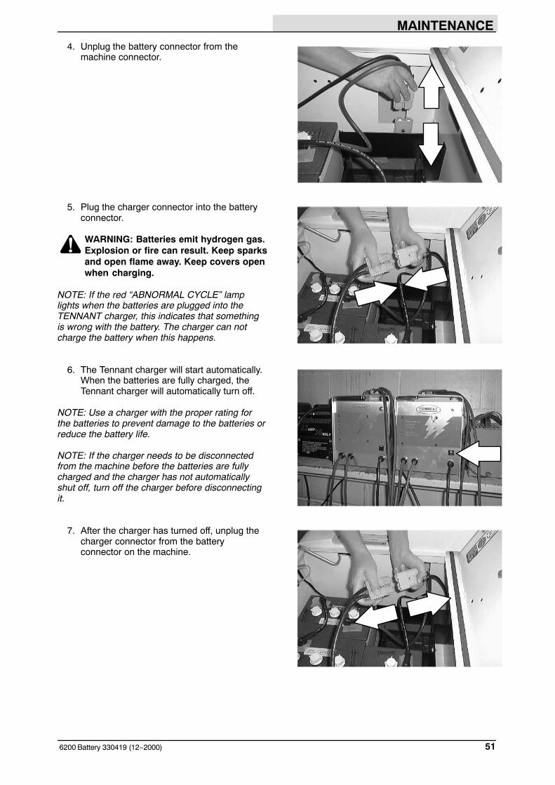
4. Unplug the battery connector from themachine connector.
5. Plug the charger connector into the batteryconnector.
WARNING: Batteries emit hydrogen gas.Explosion or fire can result. Keep sparksand open flame away. Keep covers openwhen charging.
NOTE: If the red “ABNORMAL CYCLE” lamplights when the batteries are plugged into theTENNANT charger, this indicates that somethingis wrong with the battery. The charger can notcharge the battery when this happens.
6. The Tennant charger will start automatically.When the batteries are fully charged, theTennant charger will automatically turn off.
NOTE: Use a charger with the proper rating forthe batteries to prevent damage to the batteries orreduce the battery life.
NOTE: If the charger needs to be disconnectedfrom the machine before the batteries are fullycharged and the charger has not automaticallyshut off, turn off the charger before disconnectingit.
7. After the charger has turned off, unplug thecharger connector from the batteryconnector on the machine.

MAINTENANCE
6200 Battery 330419 (9−2001)52
8. Reconnect the battery connector to themachine connector.
9. Check the electrolyte level in each batterycell after charging. If needed, add justenough distilled water to raise the electrolytelevel up to about 12mm (0.4 in) below thebottom of the sight tubes.
FOR SAFETY: When maintaining orservicing machine, avoid contact withbattery acid.
10. Close the seat support.
BELTS AND CHAINS
VACUUM FAN BELT
The vacuum fan belt drives the vacuum system.Check the belt for wear and tension after every100 hours of operation.
The correct tension is when the belt deflects 12.7mm from a force of 17 kg at belt midpoint.
FOR SAFETY: When servicing machine,avoid moving parts. Do not wear loosejackets, shirts or sleeves when workingon machine.
MAIN BRUSH BELT
The main brush belt drives the main brush. Checkthe main brush belt for wear and tension afterevery 100 hours of operation.
Set the tension with the top sheave. The correcttension on the belt is when the top sheave isputting 6 kg of pressure on the main brush belt.
FOR SAFETY: When servicing machine,avoid moving parts. Do not wear loosejackets, shirts or sleeves when workingon machine.
MAINTENANCE
536200 Battery 330419 (12−2000)
STEERING GEAR CHAIN
The steering chain turns the front wheel as thesteering wheel is turned to steer the machine.Lubricate the steering chain with SAE 30−weightengine oil after every 200 hours of operation.
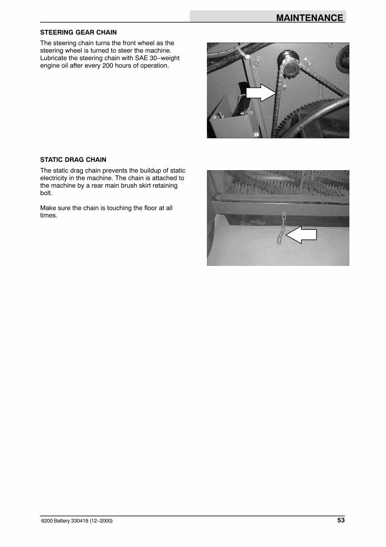
STATIC DRAG CHAIN
The static drag chain prevents the buildup of staticelectricity in the machine. The chain is attached tothe machine by a rear main brush skirt retainingbolt.
Make sure the chain is touching the floor at alltimes.
MAINTENANCE
6200 Battery 330419 (4−2008)54
DEBRIS HOPPER
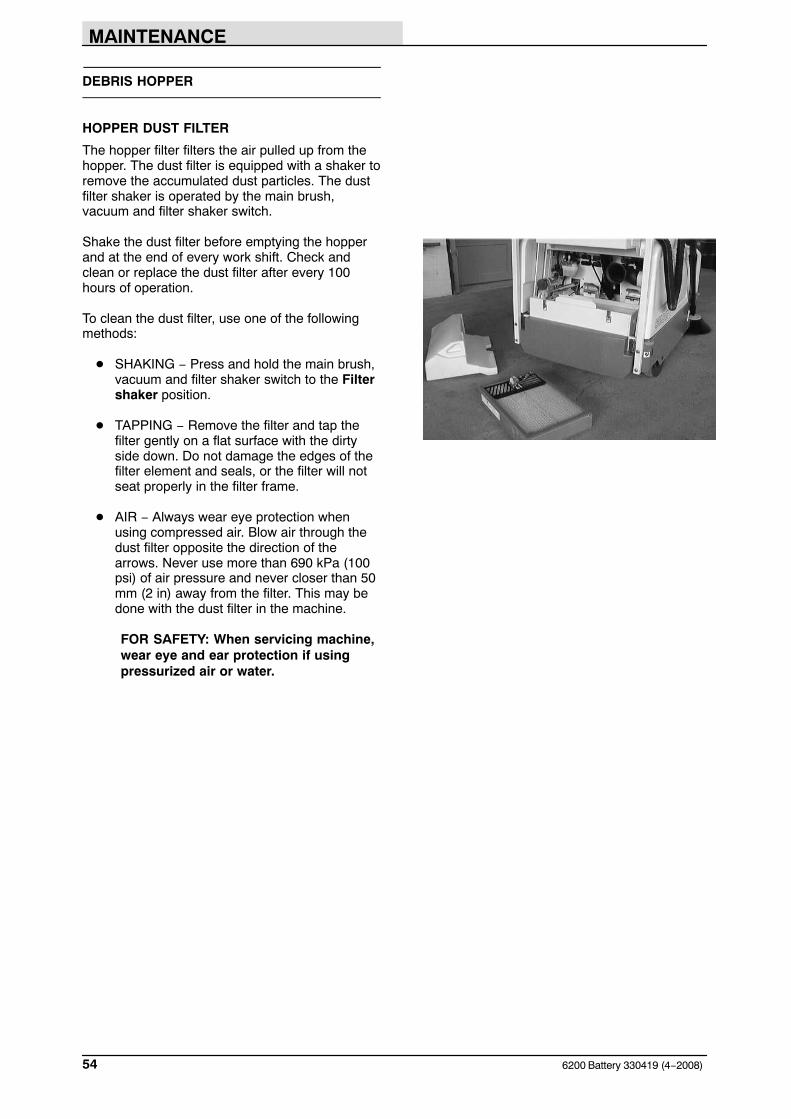
HOPPER DUST FILTER
The hopper filter filters the air pulled up from thehopper. The dust filter is equipped with a shaker toremove the accumulated dust particles. The dustfilter shaker is operated by the main brush,vacuum and filter shaker switch.
Shake the dust filter before emptying the hopperand at the end of every work shift. Check andclean or replace the dust filter after every 100hours of operation.
To clean the dust filter, use one of the followingmethods:
� SHAKING − Press and hold the main brush,vacuum and filter shaker switch to the Filtershaker position.
� TAPPING − Remove the filter and tap thefilter gently on a flat surface with the dirtyside down. Do not damage the edges of thefilter element and seals, or the filter will notseat properly in the filter frame.
� AIR − Always wear eye protection whenusing compressed air. Blow air through thedust filter opposite the direction of thearrows. Never use more than 690 kPa (100psi) of air pressure and never closer than 50mm (2 in) away from the filter. This may bedone with the dust filter in the machine.
FOR SAFETY: When servicing machine,wear eye and ear protection if usingpressurized air or water.
MAINTENANCE
556200 Battery 330419 (12−2000)
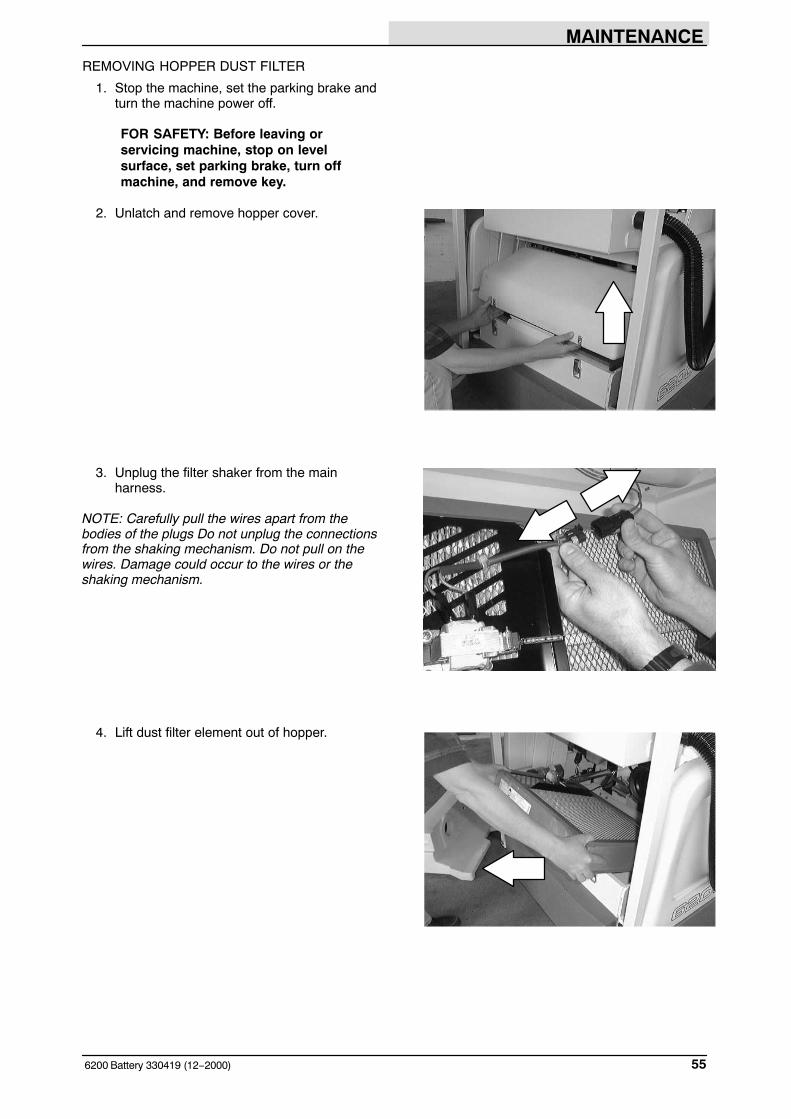
REMOVING HOPPER DUST FILTER
1. Stop the machine, set the parking brake andturn the machine power off.
FOR SAFETY: Before leaving orservicing machine, stop on levelsurface, set parking brake, turn offmachine, and remove key.
2. Unlatch and remove hopper cover.
3. Unplug the filter shaker from the mainharness.
NOTE: Carefully pull the wires apart from thebodies of the plugs Do not unplug the connectionsfrom the shaking mechanism. Do not pull on thewires. Damage could occur to the wires or theshaking mechanism.
4. Lift dust filter element out of hopper.
MAINTENANCE
6200 Battery 330419 (12−2000)56
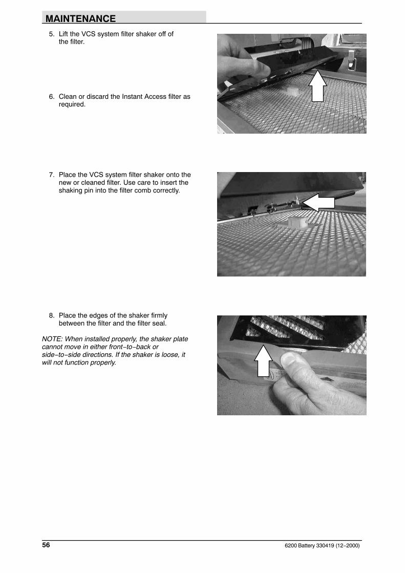
5. Lift the VCS system filter shaker off of the filter.
6. Clean or discard the Instant Access filter asrequired.
7. Place the VCS system filter shaker onto thenew or cleaned filter. Use care to insert theshaking pin into the filter comb correctly.
8. Place the edges of the shaker firmlybetween the filter and the filter seal.
NOTE: When installed properly, the shaker platecannot move in either front−to−back orside−to−side directions. If the shaker is loose, itwill not function properly.
MAINTENANCE
576200 Battery 330419 (12−2000)
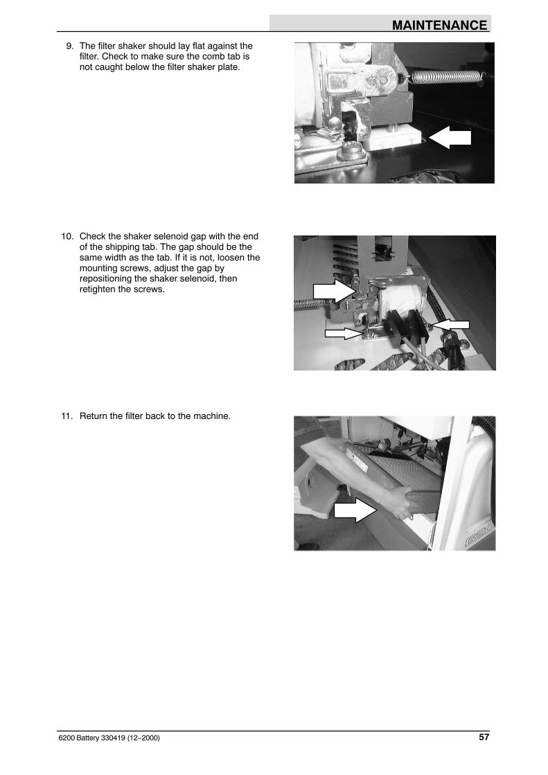
9. The filter shaker should lay flat against thefilter. Check to make sure the comb tab isnot caught below the filter shaker plate.
10. Check the shaker selenoid gap with the endof the shipping tab. The gap should be thesame width as the tab. If it is not, loosen themounting screws, adjust the gap byrepositioning the shaker selenoid, thenretighten the screws.
11. Return the filter back to the machine.

MAINTENANCE
6200 Battery 330419 (12−2000)58
12. Reconnect the main harness to the shakermechanism.
13. Check the dust filter seals.
14. Replace hopper cover and secure withlatches.
THERMO SENTRY
The Thermo Sentry is located above the debrishopper.
If a fire ignites in the hopper, the Thermo Sentrywill shut off the main brush and the vacuum fan. Ifthis occurs, drive the machine to a safe location,open the hopper and eliminate the source of heat.Turn the machine off and back on to reset theThermo Sentry.
MAINTENANCE
596200 Battery 330419 (2−2010)
BRUSHES
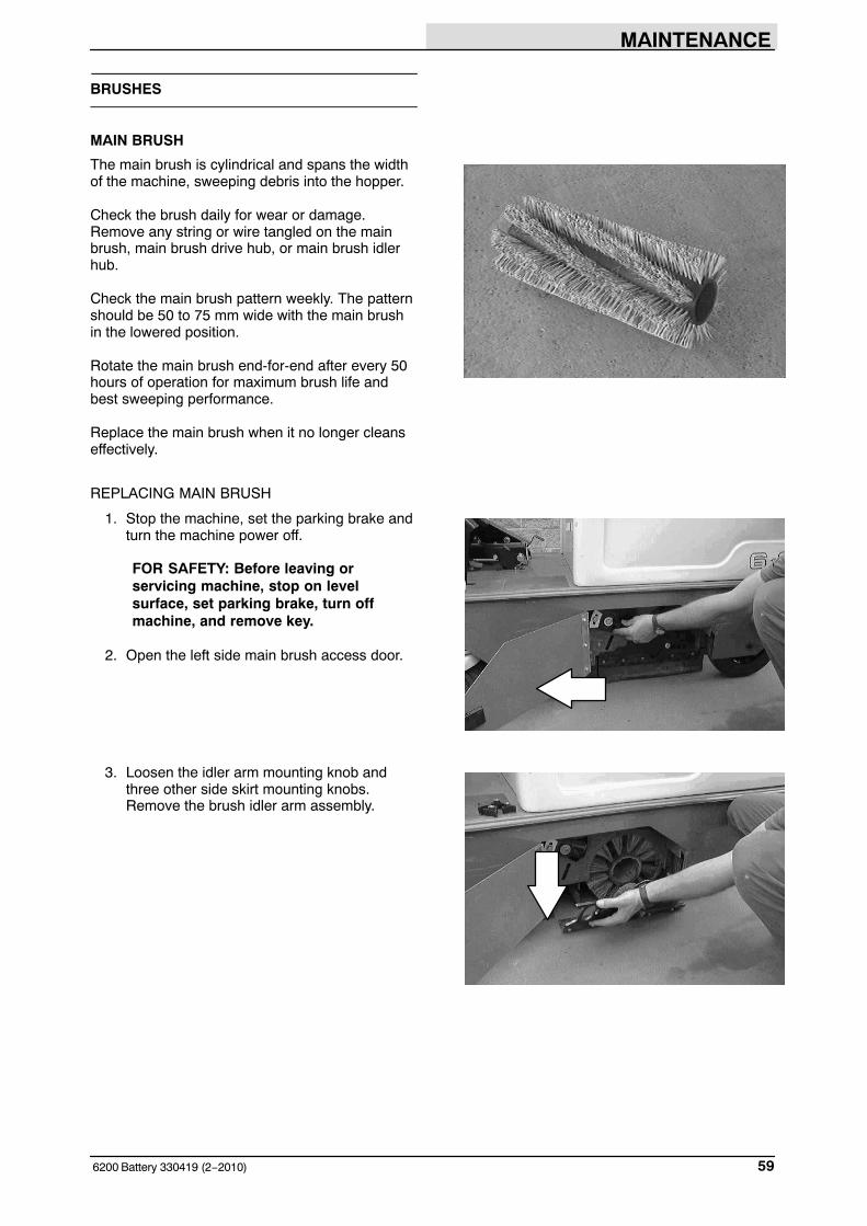
MAIN BRUSH
The main brush is cylindrical and spans the widthof the machine, sweeping debris into the hopper.
Check the brush daily for wear or damage.Remove any string or wire tangled on the mainbrush, main brush drive hub, or main brush idlerhub.
Check the main brush pattern weekly. The patternshould be 50 to 75 mm wide with the main brushin the lowered position.
Rotate the main brush end-for-end after every 50hours of operation for maximum brush life andbest sweeping performance.
Replace the main brush when it no longer cleanseffectively.
REPLACING MAIN BRUSH
1. Stop the machine, set the parking brake andturn the machine power off.
FOR SAFETY: Before leaving orservicing machine, stop on levelsurface, set parking brake, turn offmachine, and remove key.
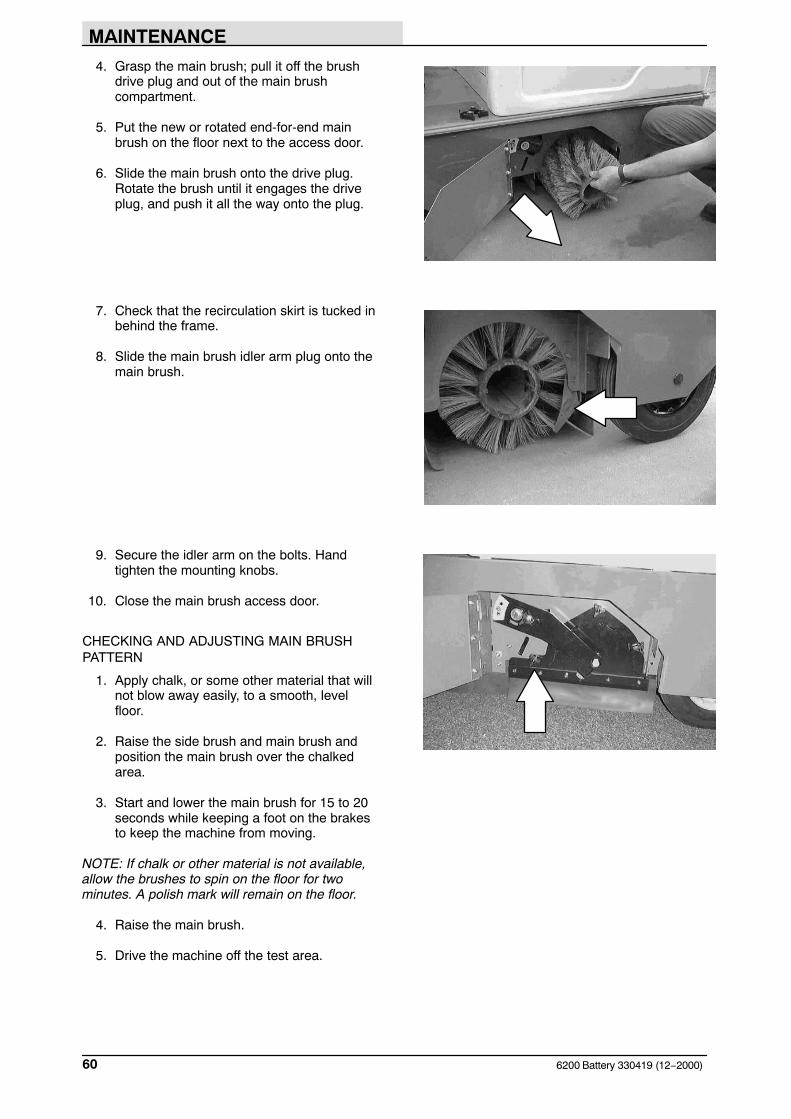
2. Open the left side main brush access door.
3. Loosen the idler arm mounting knob andthree other side skirt mounting knobs.Remove the brush idler arm assembly.
MAINTENANCE
6200 Battery 330419 (12−2000)60
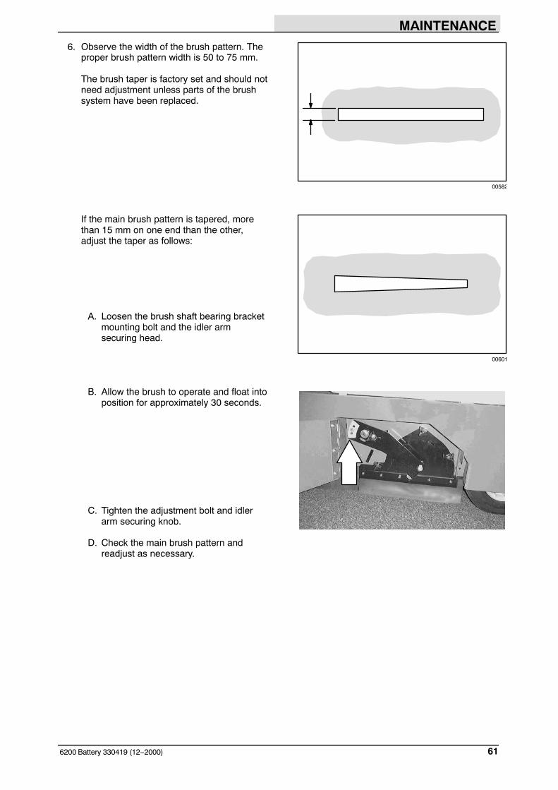
4. Grasp the main brush; pull it off the brushdrive plug and out of the main brushcompartment.
5. Put the new or rotated end-for-end mainbrush on the floor next to the access door.
6. Slide the main brush onto the drive plug.Rotate the brush until it engages the driveplug, and push it all the way onto the plug.
7. Check that the recirculation skirt is tucked inbehind the frame.
8. Slide the main brush idler arm plug onto themain brush.
9. Secure the idler arm on the bolts. Handtighten the mounting knobs.
10. Close the main brush access door.
CHECKING AND ADJUSTING MAIN BRUSHPATTERN
1. Apply chalk, or some other material that willnot blow away easily, to a smooth, levelfloor.
2. Raise the side brush and main brush andposition the main brush over the chalkedarea.
3. Start and lower the main brush for 15 to 20seconds while keeping a foot on the brakesto keep the machine from moving.
NOTE: If chalk or other material is not available,allow the brushes to spin on the floor for twominutes. A polish mark will remain on the floor.
4. Raise the main brush.
5. Drive the machine off the test area.
MAINTENANCE
616200 Battery 330419 (12−2000)
6. Observe the width of the brush pattern. Theproper brush pattern width is 50 to 75 mm.
The brush taper is factory set and should notneed adjustment unless parts of the brushsystem have been replaced.
If the main brush pattern is tapered, morethan 15 mm on one end than the other,adjust the taper as follows:
A. Loosen the brush shaft bearing bracketmounting bolt and the idler armsecuring head.
B. Allow the brush to operate and float intoposition for approximately 30 seconds.
C. Tighten the adjustment bolt and idlerarm securing knob.
D. Check the main brush pattern andreadjust as necessary.
00582
00601
MAINTENANCE
6200 Battery 330419 (2−2010)62
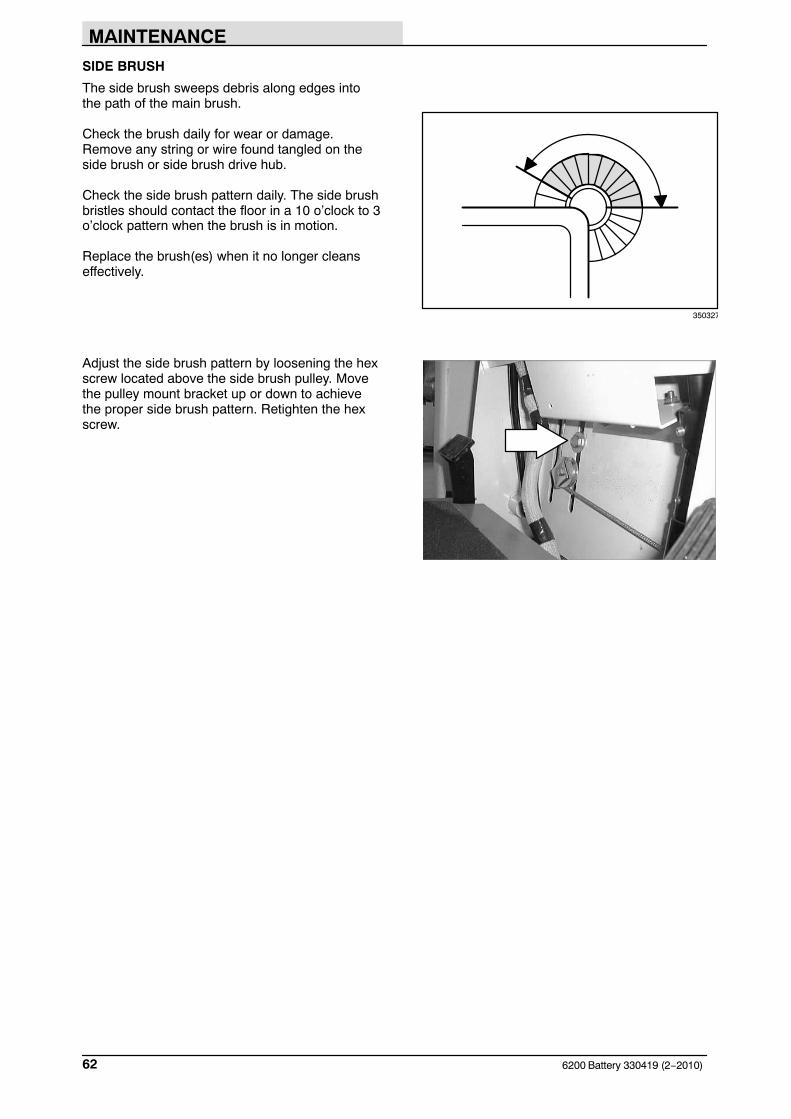
SIDE BRUSH
The side brush sweeps debris along edges intothe path of the main brush.
Check the brush daily for wear or damage.Remove any string or wire found tangled on theside brush or side brush drive hub.
Check the side brush pattern daily. The side brushbristles should contact the floor in a 10 o’clock to 3o’clock pattern when the brush is in motion.
Replace the brush(es) when it no longer cleanseffectively.
Adjust the side brush pattern by loosening the hexscrew located above the side brush pulley. Movethe pulley mount bracket up or down to achievethe proper side brush pattern. Retighten the hexscrew.
350327
MAINTENANCE
636200 Battery 330419 (12−2000)
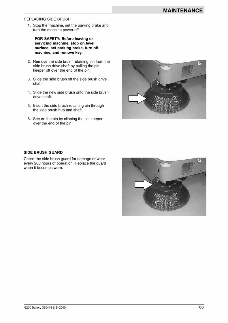
REPLACING SIDE BRUSH
1. Stop the machine, set the parking brake andturn the machine power off.
FOR SAFETY: Before leaving orservicing machine, stop on levelsurface, set parking brake, turn offmachine, and remove key.
2. Remove the side brush retaining pin from theside brush drive shaft by pulling the pinkeeper off over the end of the pin.
3. Slide the side brush off the side brush driveshaft.
4. Slide the new side brush onto the side brushdrive shaft.
5. Insert the side brush retaining pin throughthe side brush hub and shaft.
6. Secure the pin by clipping the pin keeperover the end of the pin.
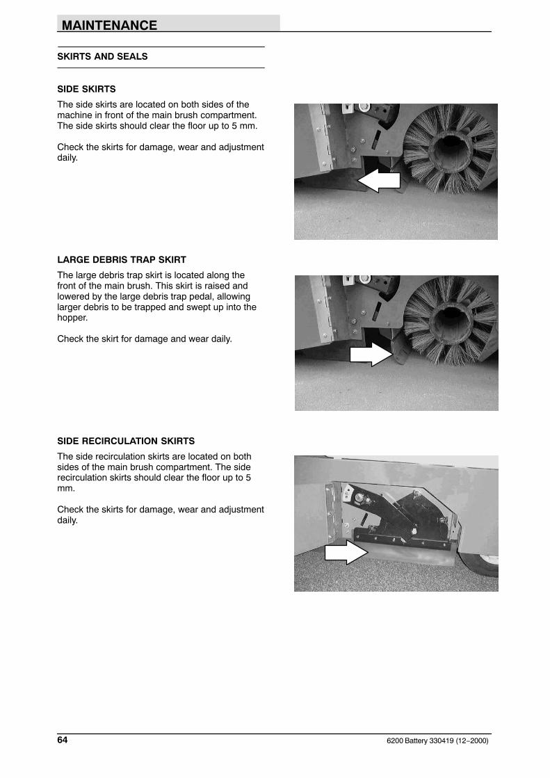
SIDE BRUSH GUARD
Check the side brush guard for damage or wearevery 200 hours of operation. Replace the guardwhen it becomes worn.
MAINTENANCE
6200 Battery 330419 (12−2000)64
SKIRTS AND SEALS
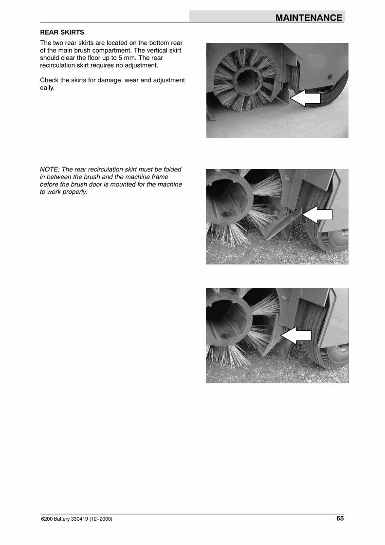
SIDE SKIRTS
The side skirts are located on both sides of themachine in front of the main brush compartment.The side skirts should clear the floor up to 5 mm.
Check the skirts for damage, wear and adjustmentdaily.
LARGE DEBRIS TRAP SKIRT
The large debris trap skirt is located along thefront of the main brush. This skirt is raised andlowered by the large debris trap pedal, allowinglarger debris to be trapped and swept up into thehopper.
Check the skirt for damage and wear daily.
SIDE RECIRCULATION SKIRTS
The side recirculation skirts are located on bothsides of the main brush compartment. The siderecirculation skirts should clear the floor up to 5mm.
Check the skirts for damage, wear and adjustmentdaily.
MAINTENANCE
656200 Battery 330419 (12−2000)
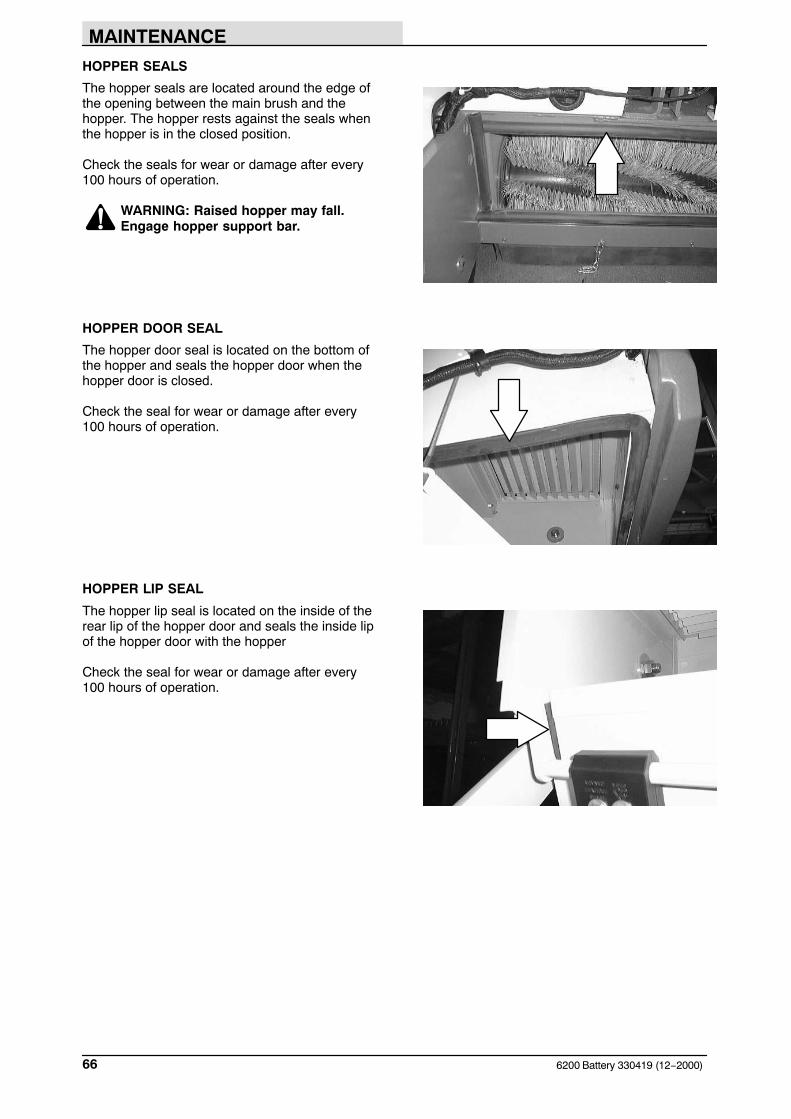
REAR SKIRTS
The two rear skirts are located on the bottom rearof the main brush compartment. The vertical skirtshould clear the floor up to 5 mm. The rearrecirculation skirt requires no adjustment.
Check the skirts for damage, wear and adjustmentdaily.
NOTE: The rear recirculation skirt must be foldedin between the brush and the machine framebefore the brush door is mounted for the machineto work properly.
MAINTENANCE
6200 Battery 330419 (12−2000)66
HOPPER SEALS
The hopper seals are located around the edge ofthe opening between the main brush and thehopper. The hopper rests against the seals whenthe hopper is in the closed position.
Check the seals for wear or damage after every100 hours of operation.
WARNING: Raised hopper may fall.Engage hopper support bar.
HOPPER DOOR SEAL
The hopper door seal is located on the bottom ofthe hopper and seals the hopper door when thehopper door is closed.
Check the seal for wear or damage after every100 hours of operation.
HOPPER LIP SEAL
The hopper lip seal is located on the inside of therear lip of the hopper door and seals the inside lipof the hopper door with the hopper
Check the seal for wear or damage after every100 hours of operation.
MAINTENANCE
676200 Battery 330419 (12−2000)
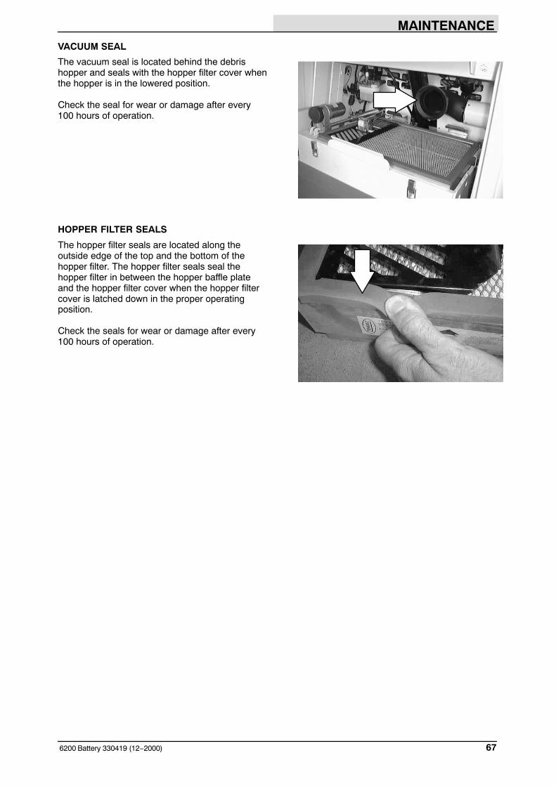
VACUUM SEAL
The vacuum seal is located behind the debrishopper and seals with the hopper filter cover whenthe hopper is in the lowered position.
Check the seal for wear or damage after every100 hours of operation.
HOPPER FILTER SEALS
The hopper filter seals are located along theoutside edge of the top and the bottom of thehopper filter. The hopper filter seals seal thehopper filter in between the hopper baffle plateand the hopper filter cover when the hopper filtercover is latched down in the proper operatingposition.
Check the seals for wear or damage after every100 hours of operation.

MAINTENANCE
6200 Battery 330419 (12−2000)68
BRAKES AND TIRES
BRAKES
The mechanical brake is located on the frontwheel. The brake is operated by the brake footpedal, connecting rods and cable.
Check the brake adjustment after every 200 hoursof operation. If the brake does not respond well topressure on the brake pedal, you may need toadjust the brake.
Adjust brake cable tension with cable nuts andbrake lever.
MAINTENANCE
696200 Battery 330419 (9−2002)
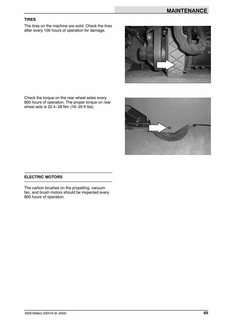
TIRES
The tires on the machine are solid. Check the tiresafter every 100 hours of operation for damage.
Check the torque on the rear wheel axles every800 hours of operation. The proper torque on rearwheel axle is 22.4−28 Nm (16−20 ft lbs).
ELECTRIC MOTORS
The carbon brushes on the propelling, vacuumfan, and brush motors should be inspected every800 hours of operation.

MAINTENANCE
6200 Battery 330419 (12−2000)70
PUSHING, TOWING, AND TRANSPORTINGTHE MACHINE
PUSHING OR TOWING THE MACHINE
If the machine becomes disabled, it can bepushed or towed from the front or rear, but it iseasier and more stable to tow from the front end.
Only push or tow the machine for a very shortdistance and do not exceed 3.2 kp/h (2 mph). It isNOT intended to be pushed or towed for a longdistance or at a high speed.
ATTENTION! Do not push or towmachine for a long distance or damagemay occur to the propelling system.
TRANSPORTING THE MACHINE
1. Position the front of the machine at theloading edge of the truck or trailer.
FOR SAFETY: Use truck or trailer thatwill support the weight of the machine.
NOTE: Empty the hopper before transporting themachine.
2. If the loading surface is not horizontal or ishigher than 380 mm (15 in) from the ground,use a winch to load machine.
If the loading surface is horizontal AND is380 mm (15 in) or less from the ground, themachine may be driven onto the truck ortrailer.
3. To winch the machine onto the truck ortrailer, attach the winching chains to the fronttie down located in the front of the machineframe.
FOR SAFETY: When loading machineonto truck or trailer, use winch. Do notdrive the machine onto the truck ortrailer unless the loading surface ishorizontal AND is 380 mm (15 in) or lessfrom the ground.
MAINTENANCE
716200 Battery 330419 (12−2000)
4. Position the machine onto the truck or traileras far as possible. If the machine starts toveer off the centerline of the truck or trailer,stop and turn the steering wheel to centerthe machine.
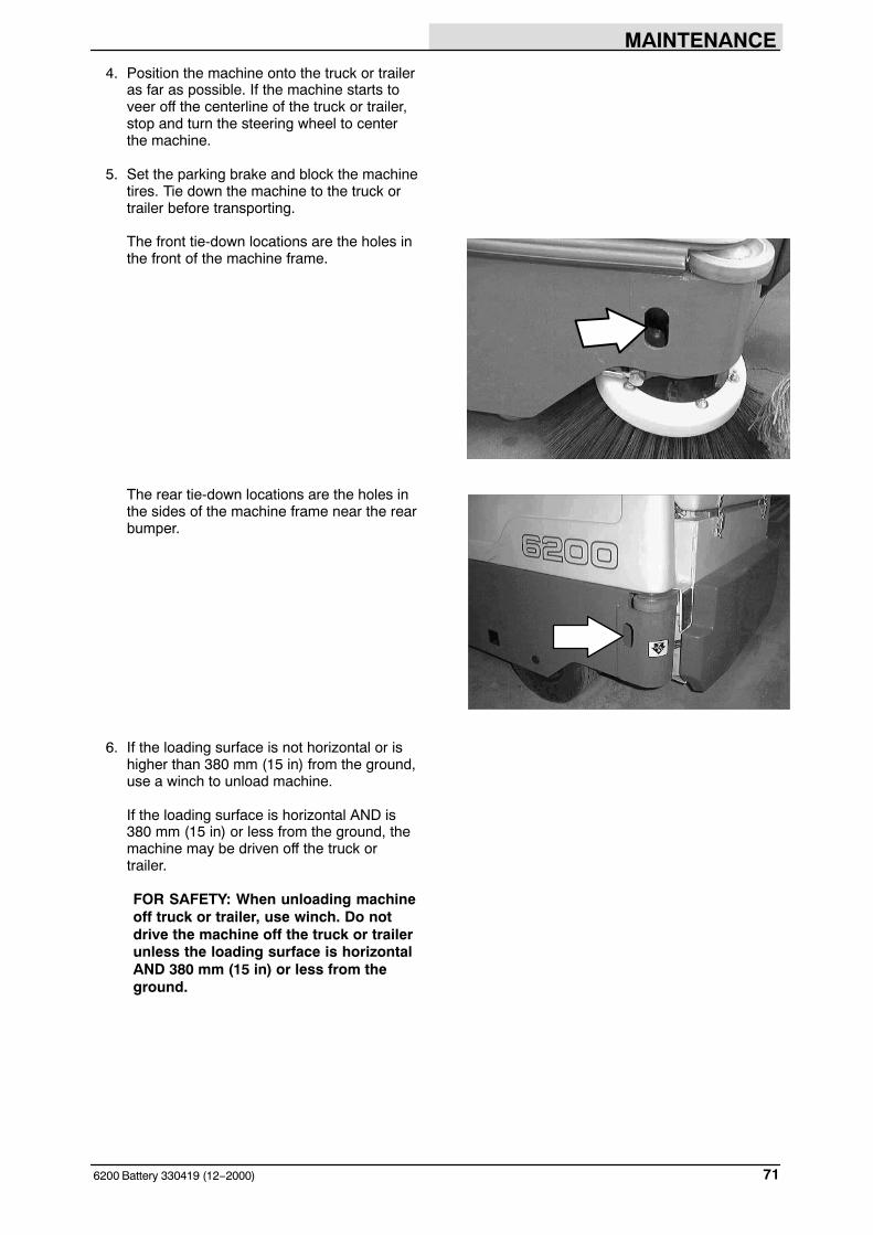
5. Set the parking brake and block the machinetires. Tie down the machine to the truck ortrailer before transporting.
The front tie-down locations are the holes inthe front of the machine frame.
The rear tie-down locations are the holes inthe sides of the machine frame near the rearbumper.
6. If the loading surface is not horizontal or ishigher than 380 mm (15 in) from the ground,use a winch to unload machine.
If the loading surface is horizontal AND is380 mm (15 in) or less from the ground, themachine may be driven off the truck ortrailer.
FOR SAFETY: When unloading machineoff truck or trailer, use winch. Do notdrive the machine off the truck or trailerunless the loading surface is horizontalAND 380 mm (15 in) or less from theground.

MAINTENANCE
6200 Battery 330419 (12−2015)72
MACHINE JACKING
Empty the hopper before jacking the machine. Youcan jack up the machine for service at thedesignated locations. Use a hoist or jack that willsupport the weight of the machine. Always stopthe machine on a flat, level surface and block thetires before jacking up the machine.
FOR SAFETY: Before leaving orservicing machine, stop on levelsurface, set parking brake, turn offmachine, and remove key.
The front jacking locations are on the flat bottomedge of the front of the machine frame.
The rear jacking locations are on the corners ofthe rear frame.
FOR SAFETY: When servicing machine,block machine tires before jacking upmachine.
FOR SAFETY: When servicing machine,jack up machine at designated locationsonly. Block machine up with jackstands.
STORING MACHINE
The following steps should be taken when storingthe machine for extended periods of time.
1. Charge the batteries before storing machineto prolong the life of the batteries.
ATTENTION: Do not expose machine torain, store indoors.
NOTE: To prevent potential machine damagestore machine in a rodent and insect freeenvironment.

SPECIFICATIONS
736200 Battery 330419 (2−2010)
SPECIFICATIONS
GENERAL MACHINE DIMENSIONS/CAPACITIES
Item Dimension/capacity
Length 1955 mm
Width 1070 mm
Width w/side brush 1117 mm
Height 1435 mm
Height with overhead guard 2045 mm
Track 94 mm
Wheelbase 97 mm
Main sweeping brush diameter 203 mm
Main sweeping brush length 710 mm
Side brush diameter 520 mm
Sweeping path width 710 mm
Sweeping path width with one side brush 1070 mm
Sweeping path width with two side brushes 1397 mm
Main sweeping brush pattern width 65 mm
Hopper weight capacity 135 kg
Hopper volume capacity 125 L
Dust filter area 4.5 sq m
Ceiling height minimum dumping clearance 2286 mm
Sound level continuous 68 ± 1 dB(A)
Sound level peak 80 ± 1 dB(C)
GVWR 923 kg
Vibration level at steering wheel does not exceed 2.5 m/s�
Vibration level at operator seat does not exceed 0.5 m/s�
GENERAL MACHINE PERFORMANCE
Item Measure
Maximum forward speed 10.0 km/h
Maximum reverse speed 4.8 km/h
Minimum aisle turn 2095 mm
Minimum turning radius, left 1400 mm
Minimum turning radius, right 1400 mm
Maximum rated incline with empty hopper 10�/18%
Maximum rated incline with full hopper 6�/11%

SPECIFICATIONS
6200 Battery 330419 (2−2010)74
POWER TYPE
Type Quantity Volts Ah Rating WeightBatteries 6 6 220 @ hr rate 177 kg
6 6 235 @ hr rate 177 kg6 6 335 @ hr rate 310 kg
Type Use VDC Kw (hp)Electric Motors Propelling 36 1.1 Kw
Scrub brush (main) 36 0.67 KwVacuum fan 36 0.60 Kw
Type VDC A Hz Phase VACCharger 36 20 60 1 240
STEERING
Type Power source Emergency steering
Front wheel, manual controlled Manual steering Manual
HYDRAULIC SYSTEM
System Capacity Fluid TypeHydraulic reservoir .53 L (.14 gal) ISO Grade 32 − below 7� C (45� F)Hydraulic total 1.4 L (.37 gal)
BRAKING SYSTEM (For machines below serialnumber 1069)
Type OperationService brakes Mechanical disc brake (1), one front wheel, cable
actuatedParking brake Utilizes service brakes, cable actuated
TIRES
Location Type SizeFront (1) Solid 101 x 305 mmRear (2) Solid 90 x 305 mm

SPECIFICATIONS
756200 Battery 330419 (9−2005)
TOP VIEW
SIDE VIEW
1783 mm (70 in)
1067 mm(42 in)
2045 mm(80.5 in)
FRONT VIEW
1435 mm(56.5 in)
1397 mm(55 in)
352945
MACHINE DIMENSIONS

SPECIFICATIONS
6200 Battery 330419 (4−2015)76