Hydrodeoxygenation and hydrocracking of solvolysed lignocellulosic.pdf
6.2.1 Introduction
Hydrocracking is a catalytic process that convertsheavy oils to lighter fractions primarily by meansof aromatic saturation, cracking, and isomerizationreactions in the presence of hydrogen. It is one oftwo major conversion processes used in modernrefining. The other process is Fluid CatalyticCracking (FCC), which is mainly used for gasolineproduction, while hydrocracking plays a moreversatile role, being equally flexible at producingmiddle distillates. Hydrocracking has been widelyaccepted because of its capability to producesuperior quality products: highest quality middledistillates; naphthas with high naphthene contentfor catalytic reformer feed; lube oil base stocks;feedstocks for FCC units and pyrolysis processesfor ethylene production.
During the last two decades of the Twentiethcentury the primary driver for growth in thedemand for fuels has been middle distillates, whileworldwide growth in gasoline demand has beenmore modest. For example, the worldwidedistillate-to-gasoline ratio in 1985 was 0.65; in2005 this ratio was approximately 1.0. The growthin middle distillate demand also coincided with astrong environmental push towards cleanerburning fuels. These factors have contributed tosurging interest in hydrocracking as the conversionprocess of choice.
As shown in Table 1, hydrocracking is anextremely versatile process. It accepts a widerange of feedstocks and produces a variety ofproducts. The process is environment-friendly inthat it eliminates compounds from petroleumproducts that would otherwise end up as hazardoussulphur and nitrogen oxides in the atmosphere.The exothermic reactions in hydrocracking result
in a low net requirement of fuel, and therefore gasemissions from the process are also low. Table 2presents the qualities of typical products fromhydrocracking.
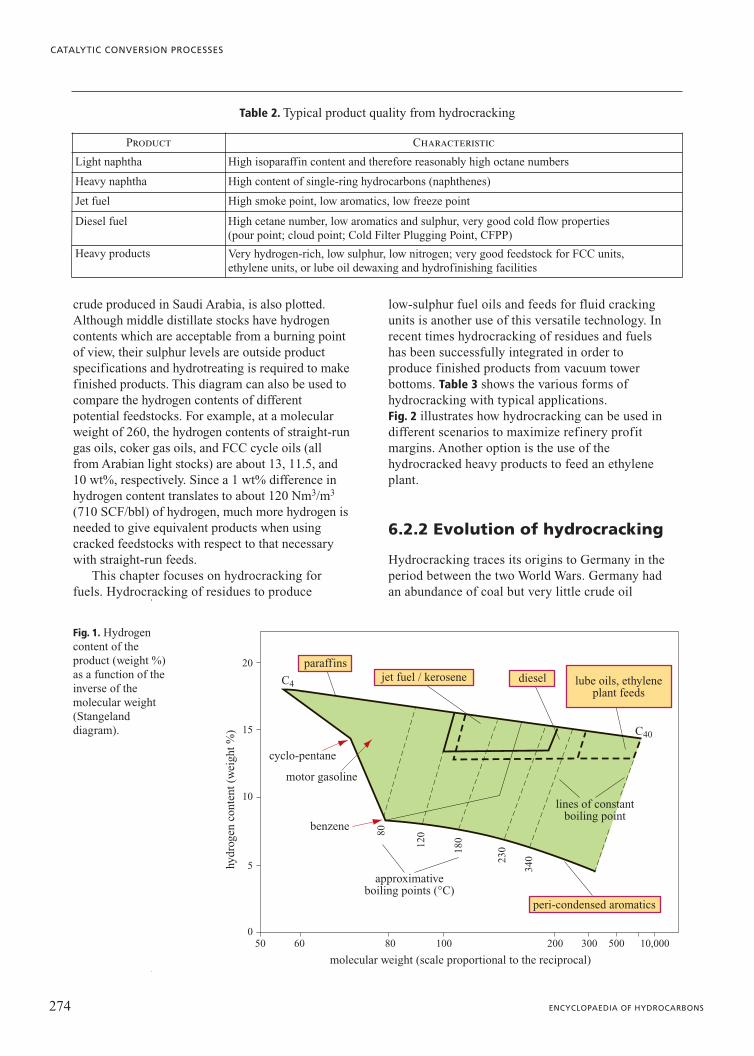
The objectives of the hydrocracking process canbe illustrated well on a Stangeland diagram asshown in Fig. 1 (Bridge and Mukherjee, 2003). On aplot of hydrogen content against molecular weight,the line representing the normal paraffins, showingthe maximum hydrogen content of hydrocarbonspresent in petroleum stocks, is drawn. Regionsrepresenting the hydrogen contents of saleablekerosene/jet fuel, diesel, and lubricating oil-basestocks are also depicted. All of these regions adjointhe normal paraffin line because the performancecharacteristics of these products suffer when low-hydrogen-content aromatic compounds are present.A curve showing the hydrogen contents of straight-run distillates of Arabian light, i.e. high-quality
273VOLUME II / REFINING AND PETROCHEMICALS
6.2
Hydrocracking
Table 1. Feed and product types from hydrocracking
Feed Primary product
Naphtha Liquefied petroleum gas
Atmospheric gas oils Naphtha, jet fuel
Light cycle oils Naphtha
Light coker gas oils Naphtha, jet fuel
Vacuum gas oils Naphtha, jet fuel, diesel
Vacuum gas oilsFCC feed, ethylene unit feed,lube unit feed
Heavy coker gas oils Jet fuel, diesel, FCC unit feed
Visbreaker gas oils Jet fuel, diesel, FCC unit feed
Deasphalted oil FCC unit feed, lube unit feed
Liquid from gas-to-liquid Diesel, lube unit feed
Aromatic extracts Jet fuel, diesel
274 ENCYCLOPAEDIA OF HYDROCARBONS
CATALYTIC CONVERSION PROCESSES
crude produced in Saudi Arabia, is also plotted.Although middle distillate stocks have hydrogencontents which are acceptable from a burning pointof view, their sulphur levels are outside productspecifications and hydrotreating is required to makefinished products. This diagram can also be used tocompare the hydrogen contents of differentpotential feedstocks. For example, at a molecularweight of 260, the hydrogen contents of straight-rungas oils, coker gas oils, and FCC cycle oils (allfrom Arabian light stocks) are about 13, 11.5, and10 wt%, respectively. Since a 1 wt% difference inhydrogen content translates to about 120 Nm3/m3
(710 SCF/bbl) of hydrogen, much more hydrogen isneeded to give equivalent products when usingcracked feedstocks with respect to that necessarywith straight-run feeds.
This chapter focuses on hydrocracking forfuels. Hydrocracking of residues to produce
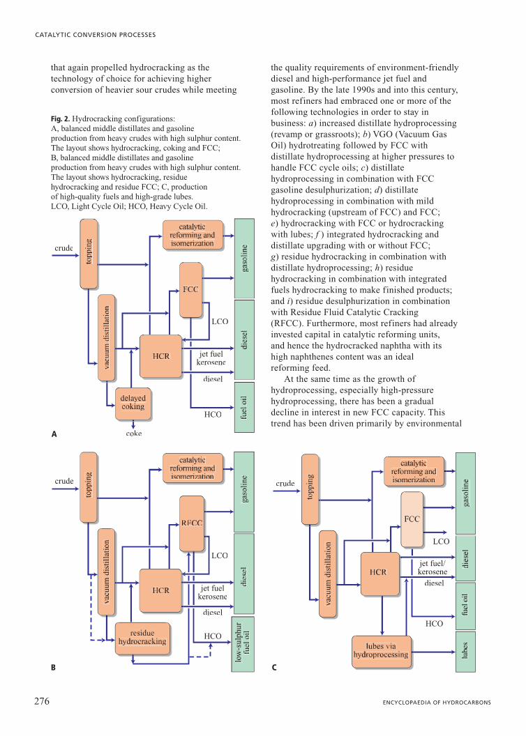
low-sulphur fuel oils and feeds for fluid crackingunits is another use of this versatile technology. Inrecent times hydrocracking of residues and fuelshas been successfully integrated in order toproduce finished products from vacuum towerbottoms. Table 3 shows the various forms ofhydrocracking with typical applications. Fig. 2 illustrates how hydrocracking can be used indifferent scenarios to maximize refinery profitmargins. Another option is the use of thehydrocracked heavy products to feed an ethyleneplant.
6.2.2 Evolution of hydrocracking
Hydrocracking traces its origins to Germany in theperiod between the two World Wars. Germany hadan abundance of coal but very little crude oil
hydr
ogen
con
tent
(w
eigh
t %)
0
5
80
120
180
230
340
10
15
20
C4
paraffins
benzene
motor gasoline
cyclo-pentane
dieseljet fuel / kerosene
peri-condensed aromatics
lines of constantboiling point
approximativeboiling points (°C)
lube oils, ethyleneplant feeds
C40
molecular weight (scale proportional to the reciprocal)
50 60 80 100 200 300 500 10,000
Fig. 1. Hydrogencontent of theproduct (weight %)as a function of theinverse of themolecular weight(Stangelanddiagram).
Table 2. Typical product quality from hydrocracking
Product Characteristic
Light naphtha High isoparaffin content and therefore reasonably high octane numbers
Heavy naphtha High content of single-ring hydrocarbons (naphthenes)
Jet fuel High smoke point, low aromatics, low freeze point
Diesel fuel High cetane number, low aromatics and sulphur, very good cold flow properties (pour point; cloud point; Cold Filter Plugging Point, CFPP)
Heavy products Very hydrogen-rich, low sulphur, low nitrogen; very good feedstock for FCC units, ethylene units, or lube oil dewaxing and hydrofinishing facilities
reserves. Intense research into coal liquefactionled to the world’s first hydrocracker in Leuna,Germany, in 1927. Conversion of coal to liquidfuels was a catalytic process, operating at veryhigh pressures (200-700 bar) and hightemperatures (375-525°C). One of the earliesthydrocracking processes to convert heavypetroleum oils to lighter fuels was a jointdevelopment between I.G. Farbenindustrie inGermany, in collaboration with Standard Oil ofNew Jersey (Scherzer and Gruia, 1996). Amongearly catalyst systems, pelleted tungsten sulphidewas the most successful (Steegstra and Mukherjee,2004). Other hydrocracking catalysts used duringthis phase were iron or nickel supported onfluorinated montmorillonite and nickel supportedon silica-alumina.
With the discovery and rapid expansion ofMiddle Eastern oil fields, the dependence on coalwaned and there was a period of low interest inhydrocracking. Newly-developed catalyticcracking processes, in particular FCC, proved tobe more economical for converting heavypetroleum fractions to gasoline. It was only in1959 that hydrocracking of petroleum fractionsbecame a commercial reality when the ChevronResearch Company, then known as the CaliforniaResearch Company, announced a newhydrocracking process called ISOCRACKING. Inthe early 1960s, the Union Oil Company, incollaboration with Esso, introduced ahydrocracking process called Unicracking-JHC.Universal Oil Products (UOP) announced theLomax hydrocracking process.
Nickel or nickel-tungsten on silica-alumina wereused as catalysts in these processes.
Several factors contributed to the rapiddevelopment of hydrocracking. The automobileindustry began to manufacture high-performancecars that required premium gasoline. As FCC unitsbecame a staple part of refinery configurations,much cracking refractory cycle stock (light andheavy cycle oils) was generated along with thegasoline. Therefore, there was an urgent need toconvert Light Cycle Oil (LCO), in particular, togasoline; this necessity was satisfied by the use ofhydrocracking. Railroads shifted from steam todiesel engines and commercial air travel increaseddramatically. The demand for diesel and lowfreezing point aviation turbine fuel, or jet fuel,increased rapidly and hydrocracking was the oneprocess that had the flexibility to meet thesedemands.
Worldwide growth continued at a steady paceuntil the early 1970s, then slowed down and thefocus shifted to the more economical FCC forgasoline production, also thanks to theintroduction of the new zeolite catalysts (Scherzerand Gruia, 1996).
Environmental lobbying in the United Statesled to a decline in grassroots construction, and inthe 1980s and early 1990s, hydrocracking grewslowly in the United States. At the same time,Europe and the emerging economies in Asia andthe Middle East witnessed rapid increases inmiddle distillate demand. From the early 1990s,first Europe and then the rest of the world startedimplementing stricter environmental regulations
275VOLUME II / REFINING AND PETROCHEMICALS
HYDROCRACKING
Table 3. Various forms of hydrocracking with typical applications
ProcessConversionlevel (%)
Primary product Product destination
Mild hydrocracking 10-35 FCC Feed FCC
Fuels hydrocracking 40-100 FCC FeedLPGNaphthasJet fuelDiesel Ethylene plant feedLube unit feed
FCCFinished productCatalytic reforming Finished productFinished productPyrolysis heatersLube units, usually employing all-hydroprocessing route
Residue hydrocracking 35-85 Low-sulphur fuel oil Synthetic fuel
Finished productPipeline to refineries
Residue hydrocracking with integrated fuelshydrocracking
30-90 Low-sulphur fuel oil Synthetic fuelFCC feedNaphtha Diesel
Finished product to power plant or other usersPipeline to refineriesFCCCatalytic reforming Finished product
that again propelled hydrocracking as thetechnology of choice for achieving higherconversion of heavier sour crudes while meeting
the quality requirements of environment-friendlydiesel and high-performance jet fuel andgasoline. By the late 1990s and into this century,most refiners had embraced one or more of thefollowing technologies in order to stay inbusiness: a) increased distillate hydroprocessing(revamp or grassroots); b) VGO (Vacuum GasOil) hydrotreating followed by FCC withdistillate hydroprocessing at higher pressures tohandle FCC cycle oils; c) distillatehydroprocessing in combination with FCCgasoline desulphurization; d) distillatehydroprocessing in combination with mildhydrocracking (upstream of FCC) and FCC; e) hydrocracking with FCC or hydrocrackingwith lubes; f ) integrated hydrocracking anddistillate upgrading with or without FCC; g) residue hydrocracking in combination withdistillate hydroprocessing; h) residuehydrocracking in combination with integratedfuels hydrocracking to make finished products;and i) residue desulphurization in combinationwith Residue Fluid Catalytic Cracking (RFCC). Furthermore, most refiners had alreadyinvested capital in catalytic reforming units, and hence the hydrocracked naphtha with its high naphthenes content was an ideal reforming feed.
At the same time as the growth ofhydroprocessing, especially high-pressurehydroprocessing, there has been a gradualdecline in interest in new FCC capacity. Thistrend has been driven primarily by environmental
276 ENCYCLOPAEDIA OF HYDROCARBONS
CATALYTIC CONVERSION PROCESSES
LCO
diesel
HCO
coke
crude
jet fuelkerosene
Fig. 2. Hydrocracking configurations: A, balanced middle distillates and gasoline production from heavy crudes with high sulphur content.The layout shows hydrocracking, coking and FCC;B, balanced middle distillates and gasolineproduction from heavy crudes with high sulphur content.The layout shows hydrocracking, residue hydrocracking and residue FCC; C, production of high-quality fuels and high-grade lubes. LCO, Light Cycle Oil; HCO, Heavy Cycle Oil.
LCO
diesel
HCO
crude
jet fuelkerosene
LCO
diesel
HCO
crude
jet fuel/kerosene
A
B C
concerns because, by itself, an FCC unit does notimprove the sulphur balance of a refinery.European demand for diesel has continued to risewith the rapid introduction of very high-performance diesel injection engines. Thedemand for distillates in China and India is alsoincreasing rapidly. Environmentally friendlymiddle distillates have thus become the primary driver for growth in hydrocracking and no slowdown is foreseen in the near future. Refiners are increasingly integratingseveral processes into a single high-pressure loopin order to save capital and to reduce refineryoperating complexity and emissions.This trend has resulted in innovative schemes for upgrading previously-cracked and straight-run material in combined residue, fuels, and distillate hydroprocessing units(Mukherjee et al., 2003; Steegstra andMukherjee, 2004).
6.2.3 Hydrocracking chemistry
There are two broad classes of reactions thatoccur in the hydrocracking process. The first classof reactions involves hydrotreating, in whichimpurities such as nitrogen, sulphur, oxygen, andmetals are removed from the feedstock. Thesecond class of reactions involves hydrocracking,in which carbon-carbon bonds are cleaved withhydrogen addition over bifunctional catalysts.
HydrotreatingHydrotreating chemistry is an integral part of
hydrocracking chemistry. The fundamentalreactions of this process are illustrated in thefollowing; for greater details see Chapter 3.1.
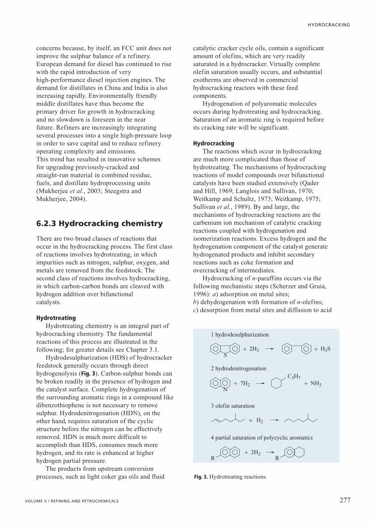
Hydrodesulphurization (HDS) of hydrocrackerfeedstock generally occurs through directhydrogenolysis (Fig. 3). Carbon-sulphur bonds canbe broken readily in the presence of hydrogen andthe catalyst surface. Complete hydrogenation ofthe surrounding aromatic rings in a compound likedibenzothiophene is not necessary to removesulphur. Hydrodenitrogenation (HDN), on theother hand, requires saturation of the cyclicstructure before the nitrogen can be effectivelyremoved. HDN is much more difficult toaccomplish than HDS, consumes much morehydrogen, and its rate is enhanced at higherhydrogen partial pressure.
The products from upstream conversionprocesses, such as light coker gas oils and fluid
catalytic cracker cycle oils, contain a significantamount of olefins, which are very readilysaturated in a hydrocracker. Virtually completeolefin saturation usually occurs, and substantialexotherms are observed in commercialhydrocracking reactors with these feedcomponents.
Hydrogenation of polyaromatic moleculesoccurs during hydrotreating and hydrocracking.Saturation of an aromatic ring is required beforeits cracking rate will be significant.
HydrocrackingThe reactions which occur in hydrocracking
are much more complicated than those ofhydrotreating. The mechanisms of hydrocrackingreactions of model compounds over bifunctionalcatalysts have been studied extensively (Qaderand Hill, 1969; Langlois and Sullivan, 1970;Weitkamp and Schultz, 1973; Weitkamp, 1975;Sullivan et al., 1989). By and large, themechanisms of hydrocracking reactions are thecarbenium ion mechanism of catalytic crackingreactions coupled with hydrogenation andisomerization reactions. Excess hydrogen and thehydrogenation component of the catalyst generatehydrogenated products and inhibit secondaryreactions such as coke formation andovercracking of intermediates.
Hydrocracking of n-paraffins occurs via thefollowing mechanistic steps (Scherzer and Gruia,1996): a) adsorption on metal sites; b) dehydrogenation with formation of n-olefins; c) desorption from metal sites and diffusion to acid
277VOLUME II / REFINING AND PETROCHEMICALS
HYDROCRACKING
2H2S
� �
2H2�
H2�
7H2
C3H7
N
R
1 hydrodesulphurization
2 hydrodenitrogenation
3 olefin saturation
4 partial saturation of polycyclic aromatics
R
� NH3�
H2S
Fig. 3. Hydrotreating reactions.
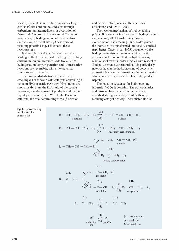
sites; d) skeletal isomerization and/or cracking ofolefins (b scission) on the acid sites throughcarbenium ion intermediates; e) desorption offormed olefins from acid sites and diffusion tometal sites; f ) hydrogenation of these olefins (n- and iso-) on metal sites; g) desorptionofresulting paraffins. Fig. 4 illustrates thesereaction steps.
It should be noted that the reaction pathsleading to the formation and cracking of a tertiarycarbenium ion are preferred. Additionally, thehydrogenation/dehydrogenation and isomerizationreactions are reversible, while the crackingreactions are irreversible.
The product distributions obtained whencracking n-hexadecane with catalysts containing arange of Hydrogenation/Acidity (H/A) ratios areshown in Fig. 5. As the H/A ratio of the catalystincreases, a wider spread of products with higherliquid yields is obtained. With high H/A ratiocatalysts, the rate-determining steps (b scission
and isomerization) occur at the acid sites(Weitkamp and Ernst, 1990).
The reaction mechanism of hydrocrackingpolycyclic aromatics involves partial hydrogenation,ring opening, alkyl transfer, ring closure,isomerization, and cracking. Once hydrogenated,the aromatics are transformed into readily-crackednaphthenes. Qader et al. (1973) documented thehydrogenation/isomerization/cracking reactionsequence and observed that the hydrocrackingreactions follow first-order kinetics with respect tofeed polyaromatic concentration. It is particularlynoteworthy that the hydrocracking of polycyclicaromatics leads to the formation of monoaromatics,which enhance the octane number of the productnaphtha.
The reaction sequence for hydrocrackingindustrial VGOs is complex. The polyaromaticsand nitrogen heterocyclic compounds areadsorbed strongly at catalytic sites, therebyreducing catalyst activity. These materials also
278 ENCYCLOPAEDIA OF HYDROCARBONS
CATALYTIC CONVERSION PROCESSES
R1n-paraffin n-olefin
secondary carbenium ion
tertiary carbenium ion
CH2CH2 R1 CHCH2 R2 CH CH2 R2
�2H
(M)
iso-olefin
carbeniumion
paraffin
iso-paraffin
R1 CH CH2 R2
�2H
(M)
R1
n-olefinCH�CH2
R1 CH
CH2 R2
CH2�CH2
CH3
R2b
(A)
R1 CHCH R1 CH2CH2 R2 CH� CH2 R2
�H�
(A)
R1 C CH2 R2�
�
�R1
iso-olefinC
CH3R1
CH2 R2
CH2�C
CH3 CH3
CH3
b
�� �
(A) R1 C CH R2
R2
�H�
(A)
�2H
(M)R1 C
CH3
CH2 R1 CH
CH3
CH3
isom.
b = beta scission
A = acid site
M = metal site
R2�
R2�
Fig. 4. Hydrocrackingmechanism forn-paraffins.
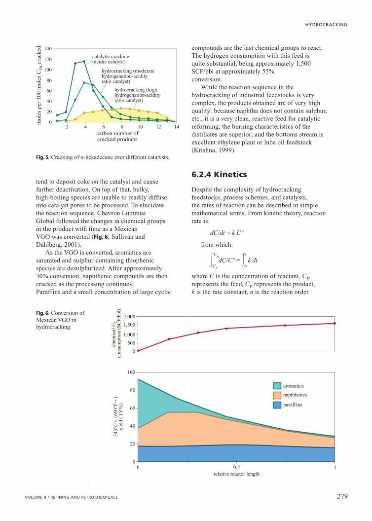
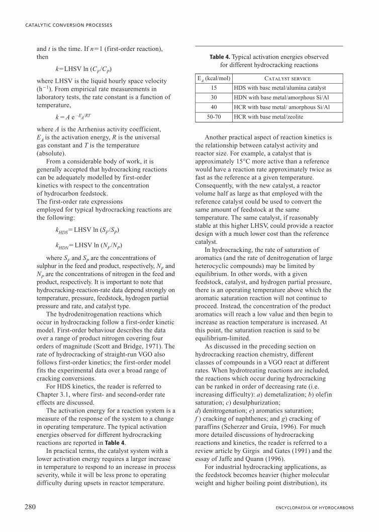
tend to deposit coke on the catalyst and causefurther deactivation. On top of that, bulky, high-boiling species are unable to readily diffuseinto catalyst pores to be processed. To elucidatethe reaction sequence, Chevron Lummus Global followed the changes in chemical groupsin the product with time as a Mexican VGO was converted (Fig. 6; Sullivan andDahlberg, 2001).
As the VGO is converted, aromatics aresaturated and sulphur-containing thiophenicspecies are desulphurized. After approximately30% conversion, naphthenic compounds are thencracked as the processing continues. Paraffins and a small concentration of large cyclic
compounds are the last chemical groups to react.The hydrogen consumption with this feed is quite substantial, being approximately 1,500SCF/bbl at approximately 55% conversion.
While the reaction sequence in thehydrocracking of industrial feedstocks is verycomplex, the products obtained are of very highquality: because naphtha does not contain sulphur,etc., it is a very clean, reactive feed for catalyticreforming; the burning characteristics of thedistillates are superior; and the bottoms stream isexcellent ethylene plant or lube oil feedstock(Krishna, 1999).
6.2.4 Kinetics
Despite the complexity of hydrocrackingfeedstocks, process schemes, and catalysts, the rates of reaction can be described in simplemathematical terms. From kinetic theory, reactionrate is:
dC/dt �k Cn
from which:
�C
P
CF
dC/Cn��t
0k dt
where C is the concentration of reactant, CFrepresents the feed, CP represents the product,k is the rate constant, n is the reaction order
279VOLUME II / REFINING AND PETROCHEMICALS
HYDROCRACKING
mol
es p
er 1
00 m
oles
C16
cra
cked
0
20
40
60
80
100
120
140
carbon number ofcracked products
catalytic cracking(acidic catalyst)
hydrocracking (moderatehydrogenation-acidityratio catalyst)
hydrocracking (highhydrogenation-acidityratio catalyst)
2 64 8 10 12 14
Fig. 5. Cracking of n-hexadecane over different catalysts.
343°
C�
(65
0°F
�)
yiel
d (
LV%
)
0
20
40
60
80
100
chem
ical
H2
cons
umpt
ion
(SC
F/b
bl)
0
500
1,000
1,500
2,000
relative reactor length0 0.5
paraffins
naphthenes
aromatics
1
Fig. 6. Conversion ofMexican VGO inhydrocracking.
and t is the time. If n�1 (first-order reaction),then
k�LHSV ln (CF/CP)
where LHSV is the liquid hourly space velocity(h�1). From empirical rate measurements inlaboratory tests, the rate constant is a function oftemperature,
k �A e –EA/RT
where A is the Arrhenius activity coefficient, EA is the activation energy, R is the universal gas constant and T is the temperature(absolute).
From a considerable body of work, it isgenerally accepted that hydrocracking reactionscan be adequately modelled by first-orderkinetics with respect to the concentration of hydrocarbon feedstock. The first-order rate expressions employed for typical hydrocracking reactions arethe following:
kHDS�LHSV ln (SF/SP)
kHDN�LHSV ln (NF/NP)
where SF and SP are the concentrations ofsulphur in the feed and product, respectively, NF andNP are the concentrations of nitrogen in the feed andproduct, respectively. It is important to note thathydrocracking-reaction-rate data depend strongly ontemperature, pressure, feedstock, hydrogen partialpressure and rate, and catalyst type.
The hydrodenitrogenation reactions whichoccur in hydrocracking follow a first-order kineticmodel. First-order behaviour describes the dataover a range of product nitrogen covering fourorders of magnitude (Scott and Bridge, 1971). Therate of hydrocracking of straight-run VGO alsofollows first-order kinetics; the first-order modelfits the experimental data over a broad range ofcracking conversions.
For HDS kinetics, the reader is referred toChapter 3.1, where first- and second-order rateeffects are discussed.
The activation energy for a reaction system is ameasure of the response of the system to a changein operating temperature. The typical activationenergies observed for different hydrocrackingreactions are reported in Table 4.
In practical terms, the catalyst system with alower activation energy requires a larger increasein temperature to respond to an increase in processseverity, while it will be less prone to operatingdifficulty during upsets in reactor temperature.
Another practical aspect of reaction kinetics isthe relationship between catalyst activity andreactor size. For example, a catalyst that isapproximately 15°C more active than a referencewould have a reaction rate approximately twice asfast as the reference at a given temperature.Consequently, with the new catalyst, a reactorvolume half as large as that employed with thereference catalyst could be used to convert thesame amount of feedstock at the sametemperature. The same catalyst, if reasonablystable at this higher LHSV, could provide a reactordesign with a much lower cost than the referencecatalyst.
In hydrocracking, the rate of saturation ofaromatics (and the rate of denitrogenation of largeheterocyclic compounds) may be limited byequilibrium. In other words, with a givenfeedstock, catalyst, and hydrogen partial pressure,there is an operating temperature above which thearomatic saturation reaction will not continue toproceed. Instead, the concentration of the productaromatics will reach a low value and then begin toincrease as reaction temperature is increased. Atthis point, the saturation reaction is said to beequilibrium-limited.
As discussed in the preceding section onhydrocracking reaction chemistry, differentclasses of compounds in a VGO react at differentrates. When hydrotreating reactions are included,the reactions which occur during hydrocrackingcan be ranked in order of decreasing rate (i.e.increasing difficulty): a) demetalization; b) olefinsaturation; c) desulphurization; d) denitrogenation; e) aromatics saturation; f ) cracking of naphthenes; and g) cracking ofparaffins (Scherzer and Gruia, 1996). For muchmore detailed discussions of hydrocrackingreactions and kinetics, the reader is referred to areview article by Girgis and Gates (1991) and theessay of Jaffe and Quann (1996).
For industrial hydrocracking applications, asthe feedstock becomes heavier (higher molecularweight and higher boiling point distribution), its
280 ENCYCLOPAEDIA OF HYDROCARBONS
CATALYTIC CONVERSION PROCESSES
Table 4. Typical activation energies observed for different hydrocracking reactions
EA (kcal/mol) Catalyst service
15 HDS with base metal/alumina catalyst
30 HDN with base metal/amorphous Si/Al
40 HCR with base metal/ amorphous Si/Al
50-70 HCR with base metal/zeolite
reaction rate is lower at a given temperature.Generally speaking, heavier feeds are processedat higher temperatures, higher hydrogenpartial pressures, and lower space velocities toobtain satisfactory product yields and qualities.
Several species in hydrocracker feeds inhibitthe activity of the catalyst. Ammonia and organicnitrogen compounds adsorb onto and block acidsites of the hydrocracking catalyst. These species‘neutralize’ the cracking sites and force thecatalyst to operate at higher temperatures to obtainequivalent conversion. In some cases,hese poisons can accelerate catalyst deactivationdue to by-product coking reactions on catalystsurfaces.
High-molecular-weight polycyclic aromaticscan also occupy active sites and lead to operatingproblems. If the catalyst system is operating athigher temperatures to process a refractoryfeedstock, these inhibitors can polymerize andgrow to form coke on both hydrogenation andcracking sites. Additionally, the presence of smallquantities of very large polycyclic aromatics (7-15ring aromatics) can lead to precipitation problemson cold equipment surfaces due to very limitedsolubility in process fluids. These very largepolycyclic aromatics can be formed in either thefirst or second stage of a hydrocracker. The rate of formation of these species must becontrolled (e.g. by proper operating temperatures,purging a heavy product stream, or separation) inorder to maintain product yield and catalystcycle length.
During operation, the hydrocracking catalystgradually loses activity (i.e. the reaction ratedecreases over time). To maintain conversion,catalyst temperature is increased. As the requiredtemperature increases per unit time are relativelysmall, the same load of catalyst can be operatedsuccessfully for several years before replacement. The cycle length of a base-metal/zeolite catalyst can exceed 5 years in service, when the temperature increase rateis approximately 0.5°C/month (Dahlberg et al., 1995).
6.2.5 Catalysts
Hydrocracking catalysts are bifunctional; i.e. theycontain two separate components. The componentwhich gives rise to the hydrogenation functionpromotes hydrogenation reactions such asdesulphurization, denitrogenation, and aromatics
saturation. The component responsible for thecracking promotes cracking reactions andisomerization reactions.
The hydrogenation function is provided bymetals which are very well dispersed throughoutthe catalyst. Typically, noble metals (platinum andpalladium) and other metals from Group VI(molybdenum, tungsten) and Group VIII (cobalt,nickel) are used in hydrocracking catalysts.
The cracking function is typically provided bysolid-acid components in the catalyst support.These acidic components usually are: amorphousoxides (silica-alumina); crystalline zeolite (e.g. Y zeolite and its modifications); or a mixtureof the first two.
Hydrocracking catalysts are carefullyformulated. The right components for eachfunction are selected, and the H/A ratio of thecatalyst is adjusted to meet selectivity (the desiredproduct) and stability (the cycle length)requirements. Additionally, the catalyst needs tobe physically strong and robust, and a balancebetween cost and performance is usuallyachieved.
Hydrogenation functionThe metal component of the hydrocracking
catalyst provides the hydrogenation/dehydrogenation function. As mentioned above, commercial catalyststypically use noble metals (platinum andpalladium) or base transition metals(molybdenum, tungsten, nickel, and cobalt).Several other metals, such as chromium, copper,iron, rhodium, and ruthenium, have also been citedas active materials for hydrocracking catalysts(Scherzer and Gruia, 1996).
The hydrogenation activity of catalytic metalsdecreases as follows: noble metals�sulphidedtransition metals�sulphided noble metals(Maxwell, 1987). For this reason, noble metalhydrocracking catalysts are commonly used invery-low-sulphur or sulphur-free environments (in a ‘clean’ second-stage reaction system with aseparate recycle gas). In some cases, sulphur ashydrogen sulphide is left in the recycle gas toreduce the hydrogenation activity of the noblemetal, thereby improving the octane number of theproduct naphtha and limiting hydrogenconsumption.
As one would expect, the amount of metal in ahydrocracking catalyst has a substantial effect onits hydrogenation function. Studies in the technicalliterature and in patent examples suggest that the noble metal loading of hydrocracking
281VOLUME II / REFINING AND PETROCHEMICALS
HYDROCRACKING
catalysts is typically �1 wt%. The base metalcontent is substantially higher, with 2-8 wt%cobalt or nickel, and 10-25 wt% molybdenum ortungsten.
Along with the absolute amount of metal, theratio of different metal components significantlyaffects the hydrogenation activity. When studyingthe saturation of toluene in the presence of H2S,the optimum atomic ratio r for Group VI and VIIIbase metals was found to be �0.25 (Franck and LePage, 1981):
MVIIIr�111112MVIII��VI
where MVI is the percentage atomic weight ofmolybdenum or tungsten and MVIII is thepercentage atomic weight of cobalt or nickel.
The hydrogenation activity of the Group VIand Group VIII metal combination increases asfollows: Co-WCo-MoNi-MoNi-W.
Cracking function
Amorphous catalyst componentsThe amorphous catalyst components serve as
the metal support and possess some crackingacidity. These amorphous components typicallyconsist of alumina, silica-alumina, fluorinatedalumina, or certain clays. They have no regularstructure on an atomic scale (i.e. they arenon-crystalline), but have a wide distribution ofpore sizes to allow high rates of moleculardiffusion and to provide large surface areas toaccommodate and disperse the metals effectively.
Alumina derived from bauxite is the startingpoint for the raw material used in hydrocrackingcatalysts. Upon hydrolysis, pseudoboehmite, amicrocrystalline type of boehmite, is formed.Aging conditions (temperature, time, or pH) affect the crystallinity and pore size of thematerial. When calcined at �300°C, g-Al2O3 isproduced. This alumina is often treated with anacid in order to obtain good catalytic and physical properties.
Amorphous silica-alumina is commonly foundin a variety of hydrocracking catalysts and can beprepared as a silica-alumina hydrogel in severalways (Scherzer and Gruia, 1996). Whilepreparation variables affect the properties of thefinal product, amorphous silica-alumina usuallyhas low-to-moderate cracking activity. The acidityis believed to be derived from the tetrahedralcoordination of aluminum in a silica host (seeChapter 6.1; Habib, 1994). The tetrahedralcoordination carries a negative charge, which is
compensated by a proton. This Brönsted acid isthen turned into a Lewis acid during thermaltreatment by dehydration.
Because of their moderate acidity, amorphoussilica-alumina hydrocracking catalysts are usuallyoperated at relatively high reactor temperaturesand low space velocities. However, this class ofcatalysts can produce very high yields of middledistillates and very high quality (high Viscosity index) waxy base oils. Additionally, due to their relatively high porosity, they areefficient for the conversion of high-boiling, heavyfeedstocks.
Zeolitic cracking componentsZeolites are crystalline, microporous alumino-
silicates with molecular sieving and sorptioncharacteristics. Many zeolites are prepared in aslurry process from sources of silica and alumina,caustic, and organic agents which function astemplates. The synthetic zeolite is furtherprocessed by ion exchange and thermal/chemicaltreatments in order to produce a catalystcomponent. Several kinds of zeolites, such asZSM-5, Y, and beta, are commonly found inhydrocracking catalysts.
Zeolitic catalyst components possess very highsurface areas and generally are very acidic (i.e.they contain many acid cracking sites). Theirmolecular sieving capabilities present diffusionallimitations to large hydrocarbon molecules (seeChapter 6.1). Consequently, in hydrocracking
282 ENCYCLOPAEDIA OF HYDROCARBONS
CATALYTIC CONVERSION PROCESSES
crystalline sodium Y
low-sodiumultrastable Y
family
ammoniumexchange to
remove sodium
Si/Al � 5Na� � 10%poor activity
Si /Al � 5 to 10Na� 0.5%
for high activitycatalysts
selective fornaphthas and jet fuel
Si /Al � 20 to 90Na� 0.05%lower activity
catalystsmore selective
for jet fuel/diesel
acid wash
steps properties
dealuminatedlow sodiumultrastable Y
family
steam calcination
steam calcination
Fig. 7. Modifying Y-zeolite for hydrocracking.
processes, these larger molecules are cracked onthe amorphous cracking sites. Due to the extensiveuse of Y zeolites in hydrocracking catalysts, theremainder of this section will focus on this familyof zeolitic components.
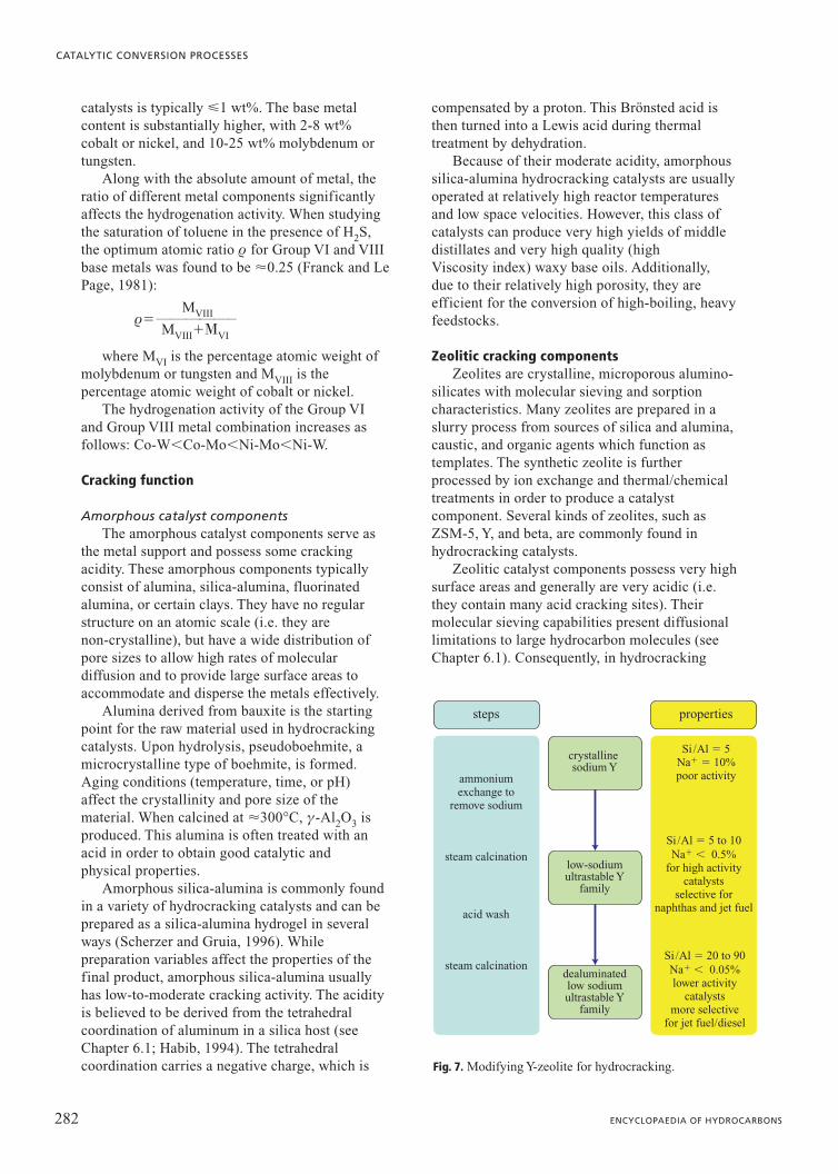
The Y-type zeolites are often modified byremoving aluminum from the framework beforethey are used in hydrocracking catalysts. Themodifications can occur in several steps andusually include ion exchange, thermal treatment,and chemical dealumination. Fig. 7 schematicallydepicts the modification process.
The typical NaY zeolite has a SiO2/Al2O3 ratioof �5, a surface area of 800 m2/g, a particle sizeof 0.5-3 mm, and �10 wt% sodium. Multipleammonium ion exchanges reduce the Na contentto �2 wt%, and a hydrothermal treatmentaccomplishes the initial dealumination. Thehydrothermal treatment is a steam calcination athigh temperatures (�540°C). The calcinationconditions, as a single step or multistage process,determine the degree of dealumination and unitcell size of the product. Subsequent ammoniumexchanges remove most of the sodium remainingin the material. At this point, the low sodiumultrastable Y zeolite is useful in high-activityhydrocracking catalysts selective for naphtha andjet liquids (Scherzer and Gruia, 1996).
If further dealumination and reduction of unitcell size is desired, acid washing coupled withsubsequent steam calcinations can be carried out.Common leaching acids are ammoniumfluorosilicate and ethylenediaminetetraacetic acid.After these treatments, the SiO2/Al2O3 ratio isincreased to the range of 20-90, and the sodiumcontent is extremely low. This class ofdealuminated Y zeolites is useful in lower activityhydrocracking catalysts which are selective for theproduction of middle distillates.
An increase in framework dealuminationreduces the unit cell size, and the resultingstructural changes in the zeolite affect its catalyticproperties (Dwyer et al., 1981). In pilot plantstudies, Bezman (1992) has found that activity,selectivity, and stability are affected significantlyby the SiO2/Al2O3 ratio of the Y zeolite used innoble metal hydrocracking catalysts.
Effects of catalyst composition on performanceZeolite catalysts are significantly more active
for hydrocracking than amorphous catalysts.Amorphous catalysts require higher temperaturesto obtain 50% conversion of a straight-run VGO,whereas zeolite catalysts deactivate at a lower rate(Hoek et al., 1991).
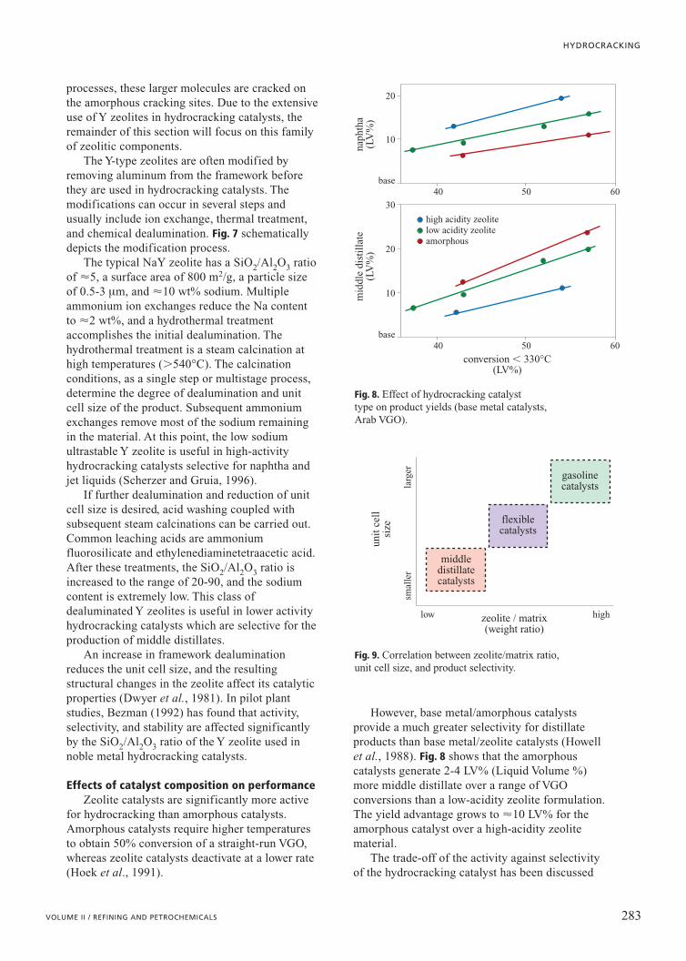
However, base metal/amorphous catalystsprovide a much greater selectivity for distillateproducts than base metal/zeolite catalysts (Howellet al., 1988). Fig. 8 shows that the amorphouscatalysts generate 2-4 LV% (Liquid Volume %)more middle distillate over a range of VGOconversions than a low-acidity zeolite formulation.The yield advantage grows to �10 LV% for theamorphous catalyst over a high-acidity zeolitematerial.
The trade-off of the activity against selectivityof the hydrocracking catalyst has been discussed
283VOLUME II / REFINING AND PETROCHEMICALS
HYDROCRACKING
base
high acidity zeolitelow acidity zeoliteamorphous
10
20
30
conversion 330°C(LV%)
40 50 60
naph
tha
(LV
%)
mid
dle
dist
illa
te(L
V%
)
base
10
20
40 50 60
Fig. 8. Effect of hydrocracking catalyst type on product yields (base metal catalysts,Arab VGO).
middledistillatecatalysts
flexiblecatalysts
larg
ersm
alle
r
gasolinecatalysts
zeolite / matrix(weight ratio)
unit
cel
lsi
ze
low high
Fig. 9. Correlation between zeolite/matrix ratio,unit cell size, and product selectivity.
by Kalnes et al. (2001). Other studies indicate thata reduction in the Unit Cell Size (UCS) of the Y-zeolite increases kerosene selectivity for basemetal/zeolite catalysts. The lower UCS catalystsalso tended to produce less C1-C4 gas. Scherzerand Gruia (1996) have put together a generalcorrelation between catalyst Y-zeolite content,UCS, and selectivity, as shown in Fig. 9.
When the zeolite content of the hydrocrackingcatalyst is relatively low (e.g. 15 wt%), the non-zeolitic component of the formula can have asubstantial impact on activity and selectivity(Ward, 1993).
6.2.6 Processes
In principle, the flow scheme for anyhydrocracking unit comprises of four differentsections: a) a high-pressure reaction loop; b) a low-pressure vapour-liquid separation section;c) a product fractionation section; and d) a make-up hydrogen compression section.
A hydrocracker consumes a large amount ofhydrogen, which is an expensive commodity inmost situations. Given that the amount oftreatment gas required in the reactor is severaltimes the chemical hydrogen consumption becauseof hydrogen partial pressure and distributionconsiderations, few refiners can afford to pass thehydrogen a single time through the reactor withoutattempting to recover the excess hydrogen in thereactor effluent. Consequently, most hydrocrackershave a significant high-pressure loop that accountsfor between 70 and 85% of the installed cost of thehydrocracker.
General process descriptionOil feed is preheated against final products,
filtered (depending on the nature of the feed), andpumped to reaction pressures using a high-headpump (Fig. 10). The oil feed is mixed withhydrogen and heated by heat exchange withreactor effluent. Final preheat is provided by areactor feed heater. There are two ways ofperforming this final preheat: either by heating themixed phase or by heating the oil and hydrogengas streams separately. Mixed-phase heatingrequires symmetrical piping in the heater which ishowever less prone to fouling compared to an oil-only heater. Providing the heat via hydrogen heatalone is feasible but requires much highertemperatures at the furnace outlet in order to raisethe oil and gas mixture temperature to reactiontemperatures. The mixed-phase reaction feed is
sent to a trickle-bed downflow reactor withmultiple beds. Depending on the conversion leveland the type of feed processed, the number of bedscan vary from two to eight.
The exothermic cracking and saturationreactions result in a large heat release thatincreases the temperature of the reactants. Thisincreased temperature further increases the rate ofreaction. In order to control this temperature riseand the rate of reaction, the catalyst is separatedinto several beds. Cold recycle gas is introducedbetween the beds to quench the reacting fluids andthereby control the extent of temperature rise andthe rate of reaction.
Reactor internals between the catalyst beds aredesigned to ensure a thorough mixing of the reactantswith the quenching gas and a good distribution of thevapour and liquid flowing down to the next bed. Aneven distribution of the reactants across the catalystbed prevents hot spots and maximizes catalystperformance and life. Most major process licensorshave invested considerable sums in research aimed atthe development of mixing devices that occupy verylittle space and at the development of redistributiontrays, downcomers, and nozzles that provide effectiveand uniform distribution of liquid and gas across theentire cross-section of the reactor. Modern,well-designed internals can reduce the radialmaldistribution to within 2-5°C for very large reactordiameters (�4 m).
Heat is recovered from the reactor effluent byheat exchange with the reactor feed, fractionationsection feed, and recycle hydrogen gas. Very often,a steam generator is incorporated in the scheme,as a reliable heat sink and as a means ofgenerating medium pressure steam to drive therecycle gas compressor turbine.
The partially cooled reactor effluent is oftenflashed in a Hot High Pressure Separator (HHPS).The HHPS permits withdrawal of the heavyunconverted oil at a high temperature so that heatinput to the product recovery section can beminimized.
Vapour from the HHPS is further cooled byheat exchange. At this point, water is continuouslyinjected into the inlet piping of the HHPS vapourair cooler to prevent the deposition of salts in theair-cooler tubes. Without the water injection,ammonia (NH3) and hydrogen sulphide (H2S),which are formed in the reactor from sulphur andnitrogen in the feed, can form ammoniumhydrogen sulphide (NH4HS) at air-coolertemperatures. This solid can deposit on theair-cooler tubes, reduce heat transfer, and eventuallyplug the tubes. Since ammonium hydrogen
284 ENCYCLOPAEDIA OF HYDROCARBONS
CATALYTIC CONVERSION PROCESSES
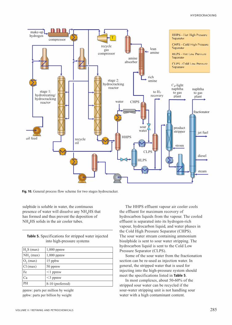
sulphide is soluble in water, the continuouspresence of water will dissolve any NH4HS thathas formed and thus prevent the deposition ofNH4HS solids in the air cooler tubes.
The HHPS effluent vapour air cooler coolsthe effluent for maximum recovery ofhydrocarbon liquids from the vapour. The cooledeffluent is separated into its hydrogen-richvapour, hydrocarbon liquid, and water phases inthe Cold High Pressure Separator (CHPS). The sour water stream containing ammoniumbisulphide is sent to sour water stripping. Thehydrocarbon liquid is sent to the Cold LowPressure Separator (CLPS).
Some of the sour water from the fractionationsection can be re-used as injection water. Ingeneral, the stripped water that is used forinjecting into the high-pressure system shouldmeet the specifications listed in Table 5.
In most complexes, about 50-60% of thestripped sour water can be recycled if thesour-water stripping unit is not handling sourwater with a high contaminant content.
285VOLUME II / REFINING AND PETROCHEMICALS
HYDROCRACKING
make-uphydrogen
oil feed
stage 1:hydrotreating/hydrocracking
reactor
stage 2:hydrocracking
reactor
water CHPS
HHPS
HLPS
CLPS
steam
productstripper
fractionator
jet fuel
diesel
steam
recycleoil
sourwater
recyclegas
compressoramine
absorber
leanamine
richamine
to H2recovery
C4-lightnaphthato gasplant
naphthato gasplant
compressor
Fig. 10. General process flow scheme for two stages hydrocracker.
Table 5. Specifications for stripped water injected into high-pressure systems
ppmw: parts per million by weight ppbw: parts per billion by weight
H2S (max) 1,000 ppmw
NH3 (max) 1,000 ppmw
O2 (max) 15 ppbw
Cl (max) 50 ppmw
Fe 1 ppmw
Ca 3 ppmw
PH 8-10 (preferred)
Such highly contaminated sour water mayoriginate from cracking units containing olefinsand cyanides.
Liquid from the HHPS is reduced in pressureand sent to the Hot Low Pressure Separator(HLPS). Hydrocarbon liquid from the CHPS iscombined with the vapour from the HLPS andcooled in an additional air cooler before enteringthe CLPS. Considering the high hydrogenconsumption in the hydrocracker, it is very oftenessential to recover as much of the hydrogen fromvarious effluent streams as economically feasible.Therefore, the hydrogen-rich vapour from theCLPS is often sent to a Pressure Swing Absorption(PSA) or membrane unit to recover hydrogen.Recovered hydrogen is sent back to the make-uphydrogen compression section.
The hydrogen-rich gas from the CHPS is sentto a recycle gas compressor either directly or via aH2S absorber, which typically uses an amine suchas MDEA (methyl diethanol amine) or DEA(diethanol amine). There are many factors thatdictate the inclusion or exclusion of the H2Sabsorber. Hydrogen sulphide, for example, canrecombine with olefins near the bottom of thereactor (desulphurization reactions are equilibriumprocesses) and affect diesel-fuel sulphurspecifications. Hydrogen sulphide can bepreferentially absorbed on the catalyst system andaffect performance. Moreover, the presence of H2Sdepresses the hydrogen partial pressure, requiringeither a high-pressure bleed from the reactor gasloop or an increase in system pressure. Mostgrassroots units producing ultra-low sulphur dieselas one of the products incorporate a H2S absorber.
The sweetened gas then flows to a knockoutdrum and then to the recycle gas compressor. Thecompressor suction line is heat traced to ensure aliquid-free vapour. The recycle compressor thendelivers the recycle gas to the reactor loop. Thereis a purge line located upstream of the recycle gascompressor that can be used, if necessary, to sendamine-sweetened recycle gas to the flare. Purginghigh-pressure gas is not required in normaloperation. Furthermore, an emergency dump lineis located upstream of the recycle gas compressorto allow a rapid reduction of pressure in therecycle loop, if necessary, in order to controlreactor temperatures during a loss of the recyclecompressor or other upsets.
Part of the recycle compressor discharge gas isrouted to the reactors where it acts as quench tocontrol the reactor temperature. The remainingrecycle gas that is not used for this function iscombined with make-up hydrogen to become the
reactor feed gas. Reliable, uninterrupted operationof the recycle compressor is essential for the safeoperation of the plant. The most reliable recyclecompressor is a centrifugal machine with a steamturbine driver.
The reactor feed gas for both stages is heatedby exchange with the HHPS vapour beforecombining with the oil feed streams to eachreaction stage.
The hydrocracking unit requires a continuoussupply of high-pressure make-up hydrogen. Inaddition to chemical consumption, hydrogenleaves the system in off-gas from the CLPS, asdissolved hydrogen in the product distillation feed,and through leaks.
The make-up hydrogen compression facilityvaries, depending on the supply pressure of thehydrogen. In most cases, very high purity (99%�)hydrogen is supplied from a PSA unit associatedwith a steam-reformer producing hydrogen fromnatural gas, Liquefied Petroleum Gas (LPG), ornaphtha. This hydrogen is available atapproximately 22 bar for optimum PSA unitrecovery. Consequently, two or very often threestages of compression are required to boost thehydrogen up to reaction pressures. Reciprocatingcompressors are used for this function, and thetypical configuration involves three 50% machines(two operating, one spare), with a commonspill-back line.
The fractionation section consists of a productstripper and an atmospheric column. It is designedto separate reaction products into light ends, heavynaphtha, kerosene, light diesel, heavy diesel, andunconverted oil.
Very often, the scope of the hydrocracking unitalso includes recovery of LPG, light naphtha, andheavy naphtha. The light-ends section (sometimescalled the gas plant) then incorporates a de-ethanizer, a naphtha stabilizer (or de-butanizer), and a naphtha splitter column. Inaddition, this section sometimes involves polishingtreatment for fuel gas, LPG, and heavy naphtha.Without equipment fouling and failure problems,plant shutdowns are usually limited to catalystregenerations or change-outs and to loss ofutilities (such as a power outage). A hydrocrackerturnaround to regenerate or replace catalystusually takes about 3-4 weeks. With typicalcatalyst cycles of 3-4 years, this would result in a97-98% onstream factor.
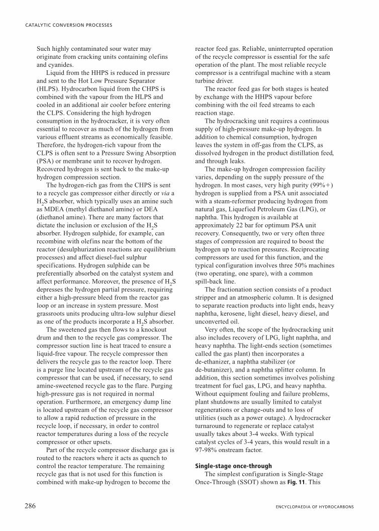
Single-stage once-throughThe simplest configuration is Single-Stage
Once-Through (SSOT) shown as Fig. 11. This
286 ENCYCLOPAEDIA OF HYDROCARBONS
CATALYTIC CONVERSION PROCESSES
scheme is widely used for mild hydrocracking and for hydrocracking to conversion levels of approximately 70%. It is the least costlyscheme per barrel of feed but more expensive per barrel of light product generated. Therefore, it is mostly used when the refiner can assign ahigh value to the heavy hydrogen-rich unconverted material or in cases when unitcapacities are too small to justify high unitcomplexity.
Depending on the other processing objectives of therefinery or the petrochemicals complex, the heavyunconverted material can be used as high quality FCCfeed, ethylene cracker feed, or as lubricating oil base stock.
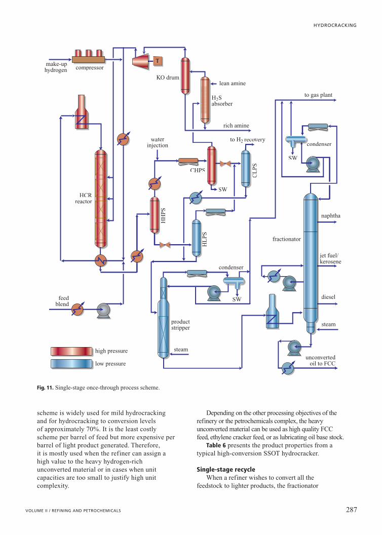
Table 6 presents the product properties from atypical high-conversion SSOT hydrocracker.
Single-stage recycleWhen a refiner wishes to convert all the
feedstock to lighter products, the fractionator
287VOLUME II / REFINING AND PETROCHEMICALS
HYDROCRACKING
steam
condenser
condenser
productstripper
fractionator
naphtha
jet fuel/kerosene
diesel
steam
unconvertedoil to FCC
H2Sabsorber
to H2 recovery
rich amine
to gas plant
lean amine
CHPS
SW
SW
waterinjection
HH
PS
HL
PS
CL
PS
feedblend
HCRreactor
make-uphydrogen compressor
KO drum
high pressure
low pressure
SW
Fig. 11. Single-stage once-through process scheme.
bottoms stream can be recycled back to the reactorand co-processed with fresh feed. There are twovariations of this Single-Stage Recycle (SSREC)configuration that have been built. In the simplestform, the combined feed is fed into a single reactor.In the second and more common variation, tworeactors are employed. The first reactor contains thehydrotreating catalyst while the second contains thehydrocracking catalyst, with recycle oil from thefractionator introduced only into the hydrocrackingreactor. However, this intermediate introductionrequires a second high-head pump for the recycleoil; most modern SSREC units have the two-reactorsystem but recycle oil is blended in with fresh feedprior to processing in the first reactor.
The hydrocracking catalyst in an SSREC scheme isexposed to the ammonia and hydrogen sulphideproduced in the hydrotreating section and thereforecannot perform as well as in a situation when thesecontaminants are absent. Reactor operatingtemperatures in the hydrocracking zone are higherthan corresponding temperatures in the second(‘clean’) stage of a Two-Stage with Recycle (TSREC,see below). The SSREC configuration is well suitedfor naphtha production or in those regions whereproduct prices for naphtha, jet, and diesel fuel aresimilar. This configuration is shown as Fig. 12.
Two-stage with recycleIn a TSREC hydrocracker configuration
shown as Fig. 13, the first stage is very similar tothe SSOT reactor. About 35-65% of theconversion is achieved in the first stage. The
fractionator bottoms is then sent to anotherreactor where the rest of the conversion occurs.Reactor effluent from this second stage is alsosent to the fractionator. The second stageoperates in the absence of ammonia andhydrogen sulphide (i.e. a ‘clean’ environment).Without the inhibiting effects of thesecontaminants, the relevant kinetic rate constantsin the clean environment are much higher than inthe first stage. Operating temperatures can bereduced by 35-40°C in the second stage, whichfavours aromatic saturation and reducedhydrocracking to light ends and naphtha,resulting in improved selectivity for diesel andbetter product qualities.
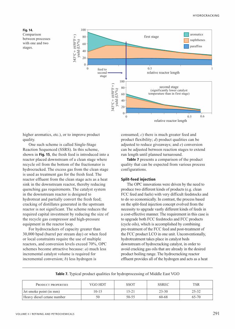
Fig. 14, which is based on Chevron LummusGlobal ISOCRACKING data on Mexican VGOover the same catalyst at a number of residencetimes, shows a comparison between processeswith one or two stages. The top portion of thefigure (already shown in Fig. 6 and here reportedfor comparison) represents a single reactor with afixed length (assumed as equal to 1). The bottomportion of the graph, which regards the insertionof the second stage downstream an additionalreactor of circa 1/3 the length of the prior(single-stage) highlights the difference incomposition of the final product. In practice, agreater conversion of paraffins and naphthenes isobtained with total length of the two reactorslesser than that of the single reactor. The feed (343°C�) of both configurations iscomposed of paraffins (18%), naphthenes (20%)
288 ENCYCLOPAEDIA OF HYDROCARBONS
CATALYTIC CONVERSION PROCESSES
Table 6. Product properties from hydrocracking in an SSOT configuration at 2,000 psia hydrogen partial pressure
Light naphtha
Heavy naphtha Jet fuel Diesel Hydrocracked
VGO
TBP cut points (°C) C5-82 82-121 121-288 288-377 377�
Gravity (°API) 84 59 44 39 38
Sulphur (ppm) 1 1 5 5 5
Nitrogen (ppm) 1 1 1 1 1
Paraffins (LV%) 83 36 35 38 46
Naphthenes (LV%) 16 58 57 54 50
Aromatics (LV%) 1 6 8 8 4
Smoke point (mm) 25
Cetane index 55
Octane number 78
Ethylene yield 32.2potential (wt %)
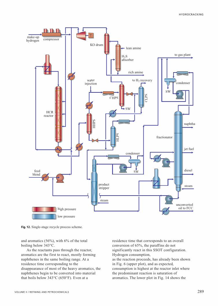
and aromatics (56%), with 6% of the total boiling below 343°C.
As the reactants pass through the reactor,aromatics are the first to react, mostly formingnaphthenes in the same boiling range. At aresidence time corresponding to thedisappearance of most of the heavy aromatics, thenaphthenes begin to be converted into materialthat boils below 343°C (650°F). Even at a
residence time that corresponds to an overallconversion of 65%, the paraffins do notsignificantly react in this SSOT configuration.Hydrogen consumption, as the reaction proceeds, has already been shownin Fig. 6 (upper plot), and as expected,consumption is highest at the reactor inlet wherethe predominant reaction is saturation ofaromatics. The lower plot in Fig. 14 shows the
289VOLUME II / REFINING AND PETROCHEMICALS
HYDROCRACKING
steam
condenser
condenser
productstripper
fractionator
naphtha
jet fuel
diesel
steam
unconvertedoil to FCC
H2Sabsorber
to H2 recovery
rich amine
to gas plant
lean amine
CHPS
SW
SW
waterinjection
HH
PS
HL
PS
CL
PS
feedblend
HCRreactor
make-uphydrogen compressor
KO drum
high pressure
low pressure
SW
Fig. 12. Single-stage recycle process scheme.
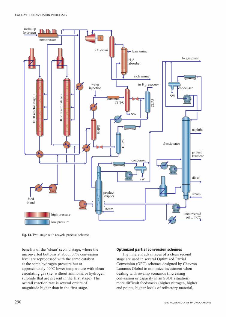
benefits of the ‘clean’ second stage, where theunconverted bottoms at about 37% conversionlevel are reprocessed with the same catalyst at the same hydrogen pressure but atapproximately 40°C lower temperature with cleancirculating gas (i.e. without ammonia or hydrogensulphide that are present in the first stage). Theoverall reaction rate is several orders ofmagnitude higher than in the first stage.
Optimized partial conversion schemesThe inherent advantages of a clean second
stage are used in several Optimized PartialConversion (OPC) schemes designed by ChevronLummus Global to minimize investment whendealing with revamp scenarios (increasingconversion or capacity in an SSOT situation),more difficult feedstocks (higher nitrogen, higherend points, higher levels of refractory material,
290 ENCYCLOPAEDIA OF HYDROCARBONS
CATALYTIC CONVERSION PROCESSES
make-uphydrogen
compressor
steam
condenser
condenser
productstripper
fractionator
naphtha
jet fuel/kerosene
diesel
steam
unconvertedoil to FCC
H2Sabsorber
to H2 recovery
rich amine
to gas plant
lean amine
waterinjection
HH
PS
HL
PS
CL
PS
KO drum
CHPS
SW
SW
HC
R r
eact
or s
tage
1
HC
R r
eact
or s
tage
2
feedblend
high pressure
low pressure
SW
Fig. 13. Two-stage with recycle process scheme.
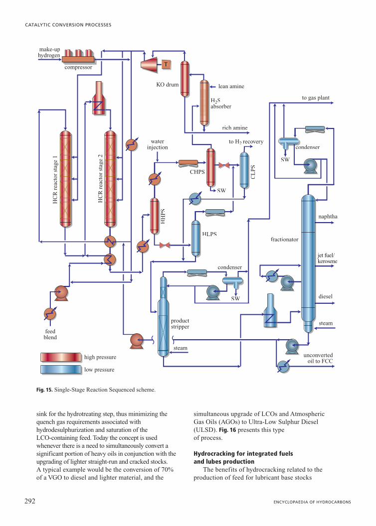
higher aromatics, etc.), or to improve productquality.
One such scheme is called Single-StageReaction Sequenced (SSRS). In this scheme,shown in Fig. 15, the fresh feed is introduced into areactor placed downstream of a clean stage whererecycle oil from the bottom of the fractionator ishydrocracked. The excess gas from the clean stageis used as treatment gas for the fresh feed. Thereactor effluent from the clean stage acts as a heatsink in the downstream reactor, thereby reducingquenching gas requirements. The catalyst systemin the downstream reactor is designed tohydrotreat and partially convert the fresh feed;cracking of distillates generated in the upstreamreactor is not significant. The scheme reduces therequired capital investment by reducing the size ofthe recycle gas compressor and high-pressureequipment in the reactor loop.
For hydrocrackers of capacity greater than30,000 bpsd (barrel per stream day) or when feedor local constraints require the use of multiplereactors, and conversion levels exceed 70%, OPCschemes become attractive because: a) much lessincremental catalyst volume is required forincremental conversion; b) less hydrogen is
consumed; c) there is much greater feed andproduct flexibility; d) product qualities can beadjusted to reduce giveaways; and e) conversioncan be adjusted between reaction stages to extendrun length until planned turnaround.
Table 7 presents a comparison of the productquality that can be expected from various processconfigurations.
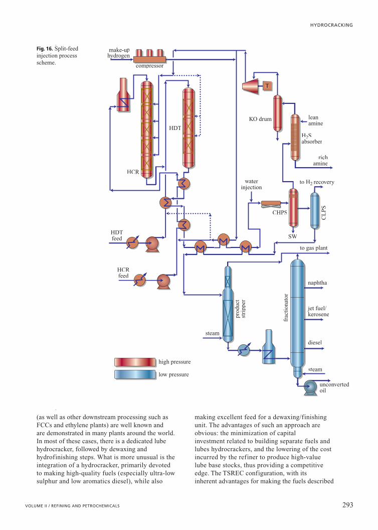
Split-feed injectionThe OPC innovations were driven by the need to
produce two different kinds of products (e.g. cleanFCC feed and fuels) with very difficult feedstocks andto do so economically. In contrast, the process basedon the split-feed injection concept evolved from thenecessity to upgrade vastly different kinds of feeds ina cost-effective manner. The requirement in this case isto upgrade both FCC feedstocks and FCC products(cycle oils), which is accomplished by combiningpre-treatment of the FCC feed and post-treatment ofthe FCC product LCO in one unit. Unconventionally,hydrotreatment takes place in catalyst bedsdownstream of hydrocracking catalyst, in order toavoid cracking gas oils that are already in the desiredproduct boiling range. The hydrocracking reactoreffluent provides all of the hydrogen and acts as a heat
291VOLUME II / REFINING AND PETROCHEMICALS
HYDROCRACKING
343°
C�
(65
0°F
�)
yiel
d (L
V%
)
343°
C�
(65
0°F
�)
yiel
d (L
V%
)
0
20
40
60
80
100
relative reactor length
relative reactor length
0 0.5
paraffins
naphthenes
aromatics
1
0
20
40
60
80
100
0 0.5 0.6
first stage
second stage(significantly lower catalyst
temperature than in first stage)
feed tosecond
stage
Fig. 14.Comparisonbetween processeswith one and twostages.
Table 7. Typical product qualities for hydroprocessing of Middle East VGO
Product properties VGO HDT SSOT SSREC TSR
Jet smoke point (in mm) 10-15 15-21 23-30 25-32
Heavy diesel cetane number 50 50-55 60-68 65-70
sink for the hydrotreating step, thus minimizing thequench gas requirements associated withhydrodesulphurization and saturation of the LCO-containing feed. Today the concept is usedwhenever there is a need to simultaneously convert asignificant portion of heavy oils in conjunction with theupgrading of lighter straight-run and cracked stocks. A typical example would be the conversion of 70%of a VGO to diesel and lighter material, and the
simultaneous upgrade of LCOs and AtmosphericGas Oils (AGOs) to Ultra-Low Sulphur Diesel(ULSD). Fig. 16 presents this type of process.
Hydrocracking for integrated fuels and lubes production
The benefits of hydrocracking related to theproduction of feed for lubricant base stocks
292 ENCYCLOPAEDIA OF HYDROCARBONS
CATALYTIC CONVERSION PROCESSES
make-uphydrogen
compressor
steam
condenser
condenser
productstripper
fractionator
naphtha
jet fuel/kerosene
diesel
steam
unconvertedoil to FCC
H2Sabsorber
to H2 recovery
rich amine
to gas plant
lean amine
waterinjection
HH
PS
HLPS
CL
PS
KO drum
CHPS
SW
SW
HC
R r
eact
or s
tage
1
HC
R r
eact
or s
tage
2
feedblend
high pressure
low pressure
SW
Fig. 15. Single-Stage Reaction Sequenced scheme.
(as well as other downstream processing such asFCCs and ethylene plants) are well known and are demonstrated in many plants around the world. In most of these cases, there is a dedicated lubehydrocracker, followed by dewaxing andhydrofinishing steps. What is more unusual is theintegration of a hydrocracker, primarily devotedto making high-quality fuels (especially ultra-lowsulphur and low aromatics diesel), while also
making excellent feed for a dewaxing/finishingunit. The advantages of such an approach areobvious: the minimization of capital investment related to building separate fuels andlubes hydrocrackers, and the lowering of the costincurred by the refiner to produce high-valuelube base stocks, thus providing a competitiveedge. The TSREC configuration, with its inherent advantages for making the fuels described
293VOLUME II / REFINING AND PETROCHEMICALS
HYDROCRACKING
frac
tion
ator
naphtha
to gas plant
unconvertedoil
jet fuel/kerosene
diesel
steam
steam
prod
uct
stri
pper
to H2 recovery
CL
PS
CHPS
SW
H2Sabsorber
richamine
leanamine
KO drum
waterinjection
make-uphydrogen
compressor
HDTfeed
HCRfeed
HCR
HDT
high pressure
low pressure
Fig. 16. Split-feedinjection processscheme.
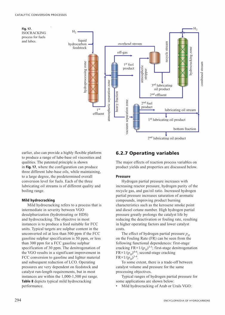
earlier, also can provide a highly flexible platformto produce a range of lube-base oil viscosities andqualities. The patented principle is shown in Fig. 17, where the configuration can producethree different lube-base oils, while maintaining,to a large degree, the predetermined overallconversion level for fuels. Each of the threelubricating oil streams is of different quality andboiling range.
Mild hydrocrackingMild hydrocracking refers to a process that is
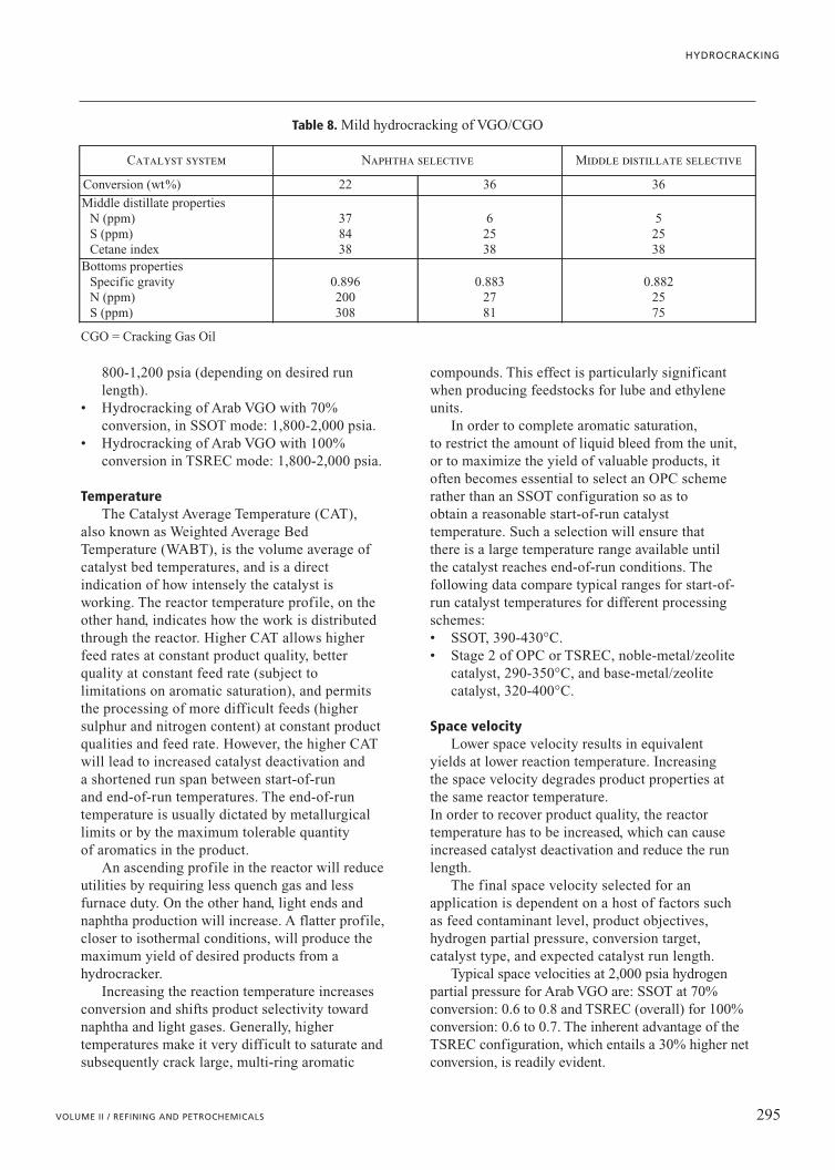
intermediate in severity between VGOdesulphurization (hydrotreating or HDS) and hydrocracking. The objective in mostinstances is to produce a feed suitable for FCCunits. Typical targets are sulphur content in theunconverted oil at less than 500 ppm if the FCCgasoline sulphur specification is 50 ppm, or lessthan 300 ppm for a FCC gasoline sulphurspecification of 30 ppm. The denitrogenation ofthe VGO results in a significant improvement inFCC conversion to gasoline and lighter materialand subsequent reduction of LCO. Operatingpressures are very dependent on feedstock andcatalyst run-length requirements, but in mostinstances are within the 1,000-1,500 psi range.Table 8 depicts typical mild hydrocrackingperformance.
6.2.7 Operating variables
The major effects of reaction process variables onproduct yields and properties are discussed below.
PressureHydrogen partial pressure increases with
increasing reactor pressure, hydrogen purity of therecycle gas, and gas/oil ratio. Increased hydrogenpartial pressure increases saturation of aromaticcompounds, improving product burningcharacteristics such as the kerosene smoke pointand diesel cetane number. High hydrogen partialpressure greatly prolongs the catalyst life byreducing the deactivation or fouling rate, resultingin higher operating factors and lower catalystcosts.
The effect of hydrogen partial pressure pHon the Fouling Rate (FR) can be seen from thefollowing functional dependences: first-stagecracking FR1/(pH)3-5; first-stage denitrogenationFR1/(pH)4-6; second-stage cracking FR1/(pH)3-4.
To some extent, there is a trade-off betweencatalyst volume and pressure for the sameprocessing objectives.
Typical ranges of hydrogen partial pressure forsome applications are shown below:• Mild hydrocracking of Arab or Urals VGO:
294 ENCYCLOPAEDIA OF HYDROCARBONS
CATALYTIC CONVERSION PROCESSES
liquidhydrocarbon
feedstock
1st
effluent
1st fuelproduct
2nd fuelproduct
2nd effluent
vacu
um s
epar
atio
n zo
neep
ar
atm
osph
eric
sep
arat
ion
zone
heav
y fr
acti
on
hydr
opro
cess
ing
zone
hydr
ocra
ckin
g zo
ne
com
bine
d st
ream
recy
cle
stre
am
atm
osph
eric
stri
pper
overhead stream
off-gas
3rd lubricatingd
oil product
lubricating oil stream
bottom fraction
1st lubricating oil product
2nd lubricating oil productd
H2H2Fig. 17.
ISOCRACKINGprocess for fuels and lubes.
800-1,200 psia (depending on desired runlength).
• Hydrocracking of Arab VGO with 70%conversion, in SSOT mode: 1,800-2,000 psia.
• Hydrocracking of Arab VGO with 100%conversion in TSREC mode: 1,800-2,000 psia.
TemperatureThe Catalyst Average Temperature (CAT),
also known as Weighted Average BedTemperature (WABT), is the volume average ofcatalyst bed temperatures, and is a directindication of how intensely the catalyst isworking. The reactor temperature profile, on theother hand, indicates how the work is distributedthrough the reactor. Higher CAT allows higherfeed rates at constant product quality, betterquality at constant feed rate (subject tolimitations on aromatic saturation), and permitsthe processing of more difficult feeds (highersulphur and nitrogen content) at constant productqualities and feed rate. However, the higher CATwill lead to increased catalyst deactivation and a shortened run span between start-of-run and end-of-run temperatures. The end-of-runtemperature is usually dictated by metallurgicallimits or by the maximum tolerable quantity of aromatics in the product.
An ascending profile in the reactor will reduceutilities by requiring less quench gas and lessfurnace duty. On the other hand, light ends andnaphtha production will increase. A flatter profile,closer to isothermal conditions, will produce themaximum yield of desired products from ahydrocracker.
Increasing the reaction temperature increasesconversion and shifts product selectivity towardnaphtha and light gases. Generally, highertemperatures make it very difficult to saturate andsubsequently crack large, multi-ring aromatic
compounds. This effect is particularly significantwhen producing feedstocks for lube and ethyleneunits.
In order to complete aromatic saturation, to restrict the amount of liquid bleed from the unit,or to maximize the yield of valuable products, itoften becomes essential to select an OPC schemerather than an SSOT configuration so as toobtain a reasonable start-of-run catalysttemperature. Such a selection will ensure thatthere is a large temperature range available untilthe catalyst reaches end-of-run conditions. Thefollowing data compare typical ranges for start-of-run catalyst temperatures for different processingschemes:• SSOT, 390-430°C.• Stage 2 of OPC or TSREC, noble-metal/zeolite
catalyst, 290-350°C, and base-metal/zeolitecatalyst, 320-400°C.
Space velocityLower space velocity results in equivalent
yields at lower reaction temperature. Increasingthe space velocity degrades product properties atthe same reactor temperature. In order to recover product quality, the reactortemperature has to be increased, which can causeincreased catalyst deactivation and reduce the runlength.
The final space velocity selected for anapplication is dependent on a host of factors suchas feed contaminant level, product objectives,hydrogen partial pressure, conversion target,catalyst type, and expected catalyst run length.
Typical space velocities at 2,000 psia hydrogenpartial pressure for Arab VGO are: SSOT at 70%conversion: 0.6 to 0.8 and TSREC (overall) for 100%conversion: 0.6 to 0.7. The inherent advantage of theTSREC configuration, which entails a 30% higher netconversion, is readily evident.
295VOLUME II / REFINING AND PETROCHEMICALS
HYDROCRACKING
Table 8. Mild hydrocracking of VGO/CGO
Catalyst system Naphtha selective Middle distillate selective
Conversion (wt%) 22 36 36
Middle distillate propertiesN (ppm)S (ppm)Cetane index
378438
62538
52538
Bottoms propertiesSpecific gravityN (ppm)S (ppm)
0.896200308
0.8832781
0.8822575
CGO = Cracking Gas Oil
Hydrogen recycle ratioIncreased hydrogen recycle decreases catalyst
fouling by increasing the hydrogen partial pressurein the reactors, by improving the distribution ofthe reaction mixture over the catalyst beds, and bylimiting the temperature rise in the catalyst beds.Overcracking of reaction products is minimized,which improves liquid yield slightly and lowershydrogen consumption. Most modernhydrocrackers are designed with a gas/oil ratio ofbetween 4 and 5 times the chemical hydrogenconsumption. Once a plant is designed, the recyclegas compressor should normally be run atmaximum capacity to reap the benefits from thecatalyst system.
Recycle Cut Point (RCP)The recycle cut point is defined as the True
Boiling Point (TBP) cut-off value between the heaviest product and the recycle oil. For agiven space velocity, lowering the RCP requiresan increase in per-pass-conversion in the reactor, and this can only be achieved byincreasing the CAT. However, this high CATincreases the catalyst deactivation rate. Loweringthe RCP generates a larger quantity of lighterproducts and increases the chemical hydrogenconsumption. The cold flow properties (pourpoint, cloud point, freeze point and cold filter plugging point) of the kerosene and diesel are improved. As a general rule, the RCP should be maximized to the productspecification limits.
Per-Pass-Conversion (PPC)Per-pass-conversion is defined as the
percentage of combined feed that is converted toproducts boiling below the RCP:
PPC�(reactor fresh feed/reactor totalfeed)�100.
Increasing the PPC requires an increase in theCAT and therefore results in a faster catalystfouling rate. The yield structure shifts towardslighter products and hydrogen consumptionincreases. The benefits are decreased hydraulicload on the reactor and therefore the possibility toincrease the throughput to the unit.
Conversely, reducing the PPC offers significantadvantages for middle distillate yields by reducinghydrocracking to lighter products. From a practicalstandpoint, PPC is rarely reduced below 50% orincreased beyond 80%.
Effect of feed qualityNitrogen. Increased nitrogen reduces cracking
activity of the catalyst. Reaction temperature mustbe increased to compensate for this reducedactivity.
Sulphur. Higher sulphur content has littleeffect on product yields and causes only a slightincrease in product sulphur.
Asphaltenes. Asphaltenes have little effect onyields or product qualities, but act as cokeprecursors and cause catalyst fouling, therebyincreasing reactor temperature and shortening thecatalyst life.
Nickel, vanadium, and other metals. Tracemetals, if not removed, poison the catalystirreversibly and decrease run length. Reactortemperature must be increased to compensate forcatalyst deactivation. Also, high levels of metalscontamination may cause part of the catalyst loadto be unregenerable.
Bibliography
Bekkum H. van et al. (editors) (2001) Introduction to zeolitescience and practice, Amsterdam, Elsevier.
Breck D.W. (1974) Zeolite molecular sieves. Structure,chemistry and use, New York, John Wiley.
Bridge A.G. et al. (1993) Cogels. A unique family of isocrackingcatalysts, in: Proceedings of the National Petrochemicaland Refiners Association annual meeting, San Antonio(TX), 21-23 March, AM-93-60.
Delannay F. (edited by) (1984) Characterization ofheterogeneous catalysts, New York, Marcel Dekker.
Deving M.L., Gland J.L. (editors) (1985) Catalystcharacterization science. Surface and solid state chemistry,Washington (D.C.), American Chemical Society.
KrishnaA.S. et al. (1999) Improved refinery conversion throughlow-cost upgrading of hydrotreaters, in: Proceedings of thePetroleum technology conference, New Dheli, January.
Mukherjee U.K. (2001) Applied isocracking technology, in:Proceedings of the Chevron Lummus Global Technologyseminar, Monte Carlo (Monaco), 7-9 October.
Shebek P.M. (1999) Catalyst supply, in: Proceedings of theChevron Lummus Global Technology seminar, SanFrancisco (CA), 3-5 May.
References
Bezman R. D. (1992) Relationship between zeolite frameworkcomposition and hydrocracking catalyst performance,«Catalysis Today», 13,143-156.
BridgeA.G., Mukherjee U.K. (2003) Isocracking-hydrocrackingfor superior fuels and lubes production, in: Handbook ofpetroleum refining processes, McGraw-Hill Engineering online, Digital Engineering Library, Chapter 7.1.
Dahlberg A.J. et al. (1995) Improved zeolite isocrackingcatalysts, in: Proceedings of the National Petrochemicaland Refiners Association annual meeting, San Francisco(CA), 19-21 March, AM-95-66.
296 ENCYCLOPAEDIA OF HYDROCARBONS
CATALYTIC CONVERSION PROCESSES
Dwyer J. et al. (1981) The surface composition of dealuminatedzeolites, «Journal of the Chemical Society. ChemicalCommunications», 9, 422-424.
Franck J.P., Le Page J.F. (1981) in: New horizons in catalysis.Proceedings of the 7th International congress on catalysis,Tokyo, 30 June-4 July 1980, Tokyo, Kodansha; Amsterdam,Elsevier, 2v.
Girgis M.J., Gates B.C. (1991) Reactivities, reaction networks,and kinetics in high-pressure catalytic hydroprocessing,«Industrial & Engineering Chemistry Research», 30, 2021-2058.
Habib M.M. (1994) New catalysts for isocracking, in:Proceedings of the Chevron Technology seminar, SanFrancisco (CA), 31 May-2 June.
Hoek A. et al. (1991) New catalyst improves heavy feedstockhydrocracking, «Oil & Gas Journal», April, 77-82.
Howell R.L. et al. (1988) Chevron HCR catalysts providerefinery flexibility, in: Proceedings of the Japan PetroleumInstitute/Petroleum Refining Conference, Tokyo, 19-21October.
Jaffe S.B., Quann R.J. (1996) Building useful models ofcomplex reaction systems in petroleum refining, «ChemicalEngineering Science», 51, 1615-1635.
Kalnes T.N. et al. (2001) Unicracking innovations deliverprofit, in: Proceedings of the National Petrochemical andRefiners Association annual meeting, New Orleans, 18-20March, AM-01-30.
Krishna A.S. (1999) Distillate hydroprocessing options tomeet EU 2005 specifications and demand, in: Proceedingsof the Chevron Lummus Global Technology seminar, Paris,22 November.
Langlois G.E., Sullivan R.F. (1970) Chemistry ofhydrocracking, «Advances in Chemistry Series», 97,38-67.
Maxwell I.E. (1987) Zeolite catalysts in hydroprocessingtechnology, «Catalysis Today», 1, 385-413.
Mukherjee U.K. et al. (2003) Latest innovations in CLG’shydroprocessing technologies, in: Proceedings of the AsianRefining Technology Conference annual meeting, Singapore,15-17 September.
Qader S.A., Hill G.R. (1969) Hydrocracking of gas oil,«Industrial & Engineering Chemistry. Process Design andDevelopment», 8, 98-105.
Qader S. et al. (1973) Hydrocracking of polynuclear aromatichydrocarbons over silica-alumina based dual functionalcatalyst, «Journal of the Institute of Petroleum», 59,178-187.
Scherzer J., Gruia A.J. (1996) Hydrocracking science andtechnology, New York, Marcel Dekker, 9-11.
Scott J.W., Bridge A.G. (1971) Continuing development ofhydrocracking, «Advances in Chemistry Series», 103,113-129.
Steegstra J., Mukherjee U.K. (2004) Integratedhydroprocessing schemes, in: Proceedings of the 4th RussianRefining Technology Conference, Moscow, September.
Sullivan R.F., Dahlberg A.J. (2001) Hydrocrackingfundamentals I and II, in: Proceedings of the ChevronLummus Global Technology seminar, Monte Carlo(Monaco), 7-9 October.
Sullivan R.F. et al. (1989) Molecular transformations inhydrotreating and hydrocracking, «Energy & Fuels», 3,603-612.
Ward J.W. (1993) Hydrocracking processes and catalysts,«Fuel Processing Technology», 35, 55-85.
Weitkamp J. (1975) Hydrocracking and hydrotreating, in:Proceedings of the 169th American Chemical Societysymposium, Philadelphia (PA), 9 April.
Weitkamp J., Ernst S. (1990) Factors influencing the selectivityof hydrocracking in zeolites, in: Barthomeuf D. et al. (editors)Guidelines for mastering the properties of molecular sieves,New York, Plenum Press, 343-354.
Weitkamp J., Schultz H. (1973) Olefinic intermediates incatalytic hydrocracking of paraffins, «Journal of Catalysis»,29, 361-366.
Arthur J. DahlbergUjjal K. Mukherjee
Chevron Lummus GlobalBloomfield, New Jersey, USA
297VOLUME II / REFINING AND PETROCHEMICALS
HYDROCRACKING