6.111 Final Project Report Beat Gunner -...
26
6.111 Final Project Report Beat Gunner: A Rhythm‐Based Shooting Game By TungShen Chew, Stephanie Cheng & An Li
-
Upload
trinhthien -
Category
Documents
-
view
213 -
download
0
Transcript of 6.111 Final Project Report Beat Gunner -...
6.111 Final Project Report
Beat Gunner: A Rhythm‐Based Shooting Game By TungShen Chew, Stephanie Cheng & An Li
1
Abstract This design report describes a video game where the player fires a gun at two moving targets on a
screen and is rewarded for hitting them in time with the beat of the music. The music is provided by an external audio source and the game performs real‐time beat‐detection to locate the beats.
2
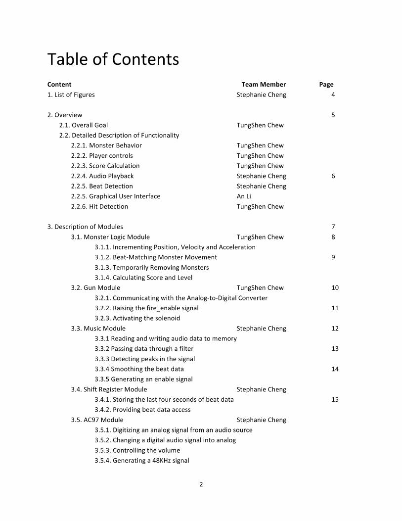
Table of Contents Content Team Member Page
1. List of Figures Stephanie Cheng 4 2. Overview 5
2.1. Overall Goal TungShen Chew 2.2. Detailed Description of Functionality
2.2.1. Monster Behavior TungShen Chew
2.2.2. Player controls TungShen Chew 2.2.3. Score Calculation TungShen Chew
2.2.4. Audio Playback Stephanie Cheng 6 2.2.5. Beat Detection Stephanie Cheng 2.2.5. Graphical User Interface An Li
2.2.6. Hit Detection TungShen Chew
3. Description of Modules 7
3.1. Monster Logic Module TungShen Chew 8 3.1.1. Incrementing Position, Velocity and Acceleration 3.1.2. Beat‐Matching Monster Movement 9
3.1.3. Temporarily Removing Monsters 3.1.4. Calculating Score and Level 3.2. Gun Module TungShen Chew 10
3.2.1. Communicating with the Analog‐to‐Digital Converter 3.2.2. Raising the fire_enable signal 11 3.2.3. Activating the solenoid
3.3. Music Module Stephanie Cheng 12 3.3.1 Reading and writing audio data to memory 3.3.2 Passing data through a filter 13
3.3.3 Detecting peaks in the signal 3.3.4 Smoothing the beat data 14 3.3.5 Generating an enable signal
3.4. Shift Register Module Stephanie Cheng 3.4.1. Storing the last four seconds of beat data 15
3.4.2. Providing beat data access
3.5. AC97 Module Stephanie Cheng 3.5.1. Digitizing an analog signal from an audio source
3.5.2. Changing a digital audio signal into analog
3.5.3. Controlling the volume 3.5.4. Generating a 48KHz signal

3
3.6. Video Module An Li 16 3.6.1 Objects and Layers
3.6.2 Video Overlay 3.6.3 Timing and Pipeline 3.6.4 Game State 17
3.6.5 Gun Shoot Detection 18 3.6.6 Graphics Generation 3.6.7 Generating BRAM Address 19
3.6.8. Monster Submodule 3.6.9. Music Note Submodule 20 3.6.10. Beat Bar Submodule
3.6.11. Edge Submodule 3.6.12. Score Submodule 21 3.6.13. Numbers Submodule
3.6.14. Hit Submodule and Miss Subodule 3.6.15 Start Submodule and Gameover Submodule 22
4. Testing 4.1. Testing the Monster Logic Module TungShen Chew 23 4.2. Testing the Gun Module TungShen Chew
4.3. Testing the Music Module Stephanie Cheng 4.4 Testing the Video Module Stephanie Cheng
5. Conclusion Stephanie Cheng 24
6. Future Improvements
6.1. Phototransistor Optics TungShen Chew
6.2. Visible Wavelength Phototransistor TungShen Chew 6.3. Sound Effects TungShen Chew 6.4. Improved Beat Detection Stephanie Cheng 25
7. References

4
1. List of Figures Figure Description Page
Figure 1: Breakdown of Hit Detection Algorithm 7
Figure 2: Top‐Level Block Diagram of the Game 7
Figure 3: Internal Structure of the Gun Module 10 Figure 4: High‐Speed Phototransistor Amplifier and ADC Communication 10
Figure 5: Internal Structure of the Music Module 12
Figure 6: Dynamic Threshold Calculation Using a Moving Window 13 Figure 7: Monster graphics 16
Figure 8: Music note graphics 16
Figure 9: Beat bar graphics 17 Figure 10: Edge graphics 17
Figure 11: Score and level graphics 17
Figure 12: Numbers graphics 17 Figure 13: Hit and miss graphics 18
Figure 14: Start and game over graphics 18

5
2. Overview 2.1. Overall Goal The main goal of this project is to design a video game with the following functionality:
• The player fires at one of two moving targets on the screen using a light gun. • The background music is supplied by an analog audio source (iPod, CD player, etc.).
• Music beats are detected in real time and displayed as scrolling lines on top of the screen. • The player earns more points by shooting the targets in time with the beat of the music.
2.2. Description of Functionality 2.2.1. Monster Behavior
The monster behavior is designed to have the following properties: • The monsters move in complex patterns with gradually changing velocity and acceleration.
Whenever a beat is detected, the monsters randomly change their velocity and acceleration to
appear as if they are dancing to the beat. • A monster which has been shot disappears for about 1.6 seconds before reentering the game
from a random corner of the screen.
• Monsters bounce off the top and bottom of the screen but wrap around the left and right edges of the screen.
• The speed of the monsters changes with respect to the game level, doubling at level 3 and again
at level 8. 2.2.2. Player controls
The game features the following player controls: • A light gun which accurately senses the light levels entering its barrel. It has a trigger for firing
the gun and a toggle switch for switching between automatic and semi‐automatic fire modes.
When the gun is fired, an attached solenoid moves to simulate recoil. • Buttons to reset the game and control the music volume. • Switches which allow the player to adjust the hit detection sensitivity.
2.2.3. Score Calculation When the player successfully shoots a target, the game increments the score by a centre‐weighted sum
of ‘yes beat’ signals situated in time around the moment when the player fired. This uses the following formula:
where beat[t] is either 1 or 0, and indicates the presence of a beat at time t∙(0.05 seconds) relative to
the moment the player fired. The game level increments every time the player achieves an additional 64 points of score.

6
2.2.4. Audio Playback Playback of the audio data is delayed by an interval of three seconds in order to allow the game graphic
to display three seconds of upcoming beats, thereby allowing the player to anticipate the arrival of beats in the music. The music module accomplishes this by sampling the digitized audio data that is provided by the AC97 module from an analog sound source. The latest three seconds of sampled audio data is
stored in memory. The music module then fetches the audio data that was written to memory three seconds earlier, and returns this to the AC97 module to be converted back into an analog audio signal.
2.2.5. Beat Detection Beat detection is performed in real‐time in order to allow the game to determine monster movements
and game scoring. The music module does this by defining any unusually large signals in the sub‐bass frequency range to be a beat. A low‐pass filter is performed on the sampled audio signal, which attenuates any frequencies above 100Hz.
The filtered audio data is then downsampled and processed by a peak finder to determine when the
beats occur. The peak finder declares that a beat occurs in the audio signal when the signal value exceeds an upper threshold or falls below a lower threshold. These two thresholds are defined by the maximum and minimum signal values within a moving window consisting of the latest two seconds of
audio data. The beats determined by the peak finder are then cleaned up and further downsampled before being placed in the shift register, which stores and allows the rest of the game logic to access the last four seconds of beat data.
2.2.5. Graphical User Interface In this game, we use a 60Hz 800 x 600 SVGA display with a 40MHz clock. The graphics modules generate
video images for the game to display on the screen. The video images include the scrolling beat bar, the monsters, the game score, and some visual effects. It also communicates with the gun module to detect the gun hits. The graphics of the game are sprite‐based. Thirteen sprites are implemented to make up
the whole image. These pre‐drawn pictures are stored in the BRAM. 2.2.6. Hit Detection
Hit detection is performed by a finite state machine which uses the light levels entering the gun barrel to determine if the player has successfully shot a target. The following steps are performed when the player presses the trigger:
1. The game sets the whole screen to black. 2. The observed light level of the gun is recorded. 3. A white box is drawn at the location of a target.
4. The game checks if the observed light level has increased. 5. Steps 1 to 4 are repeated for each target.

7
This algorithm requires a total of 4 video frames, which means that the game display is interrupted for 0.067 seconds. In game testing, this interruption time was short enough to be almost undetectable by
the player. This sequence can be visualized in the diagram below:
Figure 1: Breakdown of Hit Detection Algorithm
3. Description of Modules The game consists of six major interconnected modules. This modularity simplifies testing and allows for changes to be easily made to specific features.
Figure 2: Top‐Level Block Diagram of the Game
8
The modules are described below in the following order: 3.1. Monster Logic Module
3.2. Gun Module 3.3. Music Module 3.4. Shift Register Module
3.5 AC97 Module 3.6. Video Module
3.1. Monster Logic Module The monster logic module performs the following functions:
• Incrementing position, velocity and acceleration with respect to the current game level. • Beat‐matching monster movement to make monsters dance to the music beat.
• Temporarily removing monsters when they have been successfully hit. • Calculating score and level based on how close successful hits match up with the music beat.
3.1.1. Incrementing Position, Velocity and Acceleration The position, velocity and acceleration of the monsters are updated at 60Hz after each video screen has been drawn, to prevent updates from occurring while the screen is being rendered. On update cycles
where the rising edge of a beat has not been detected, the magnitudes of the velocity and the acceleration are gradually reduced to bring the monster to a very slow constant glide. This makes the monsters appear to be less active when the beats in the music are spaced farther apart. The position is
only incremented by the upper few bits of the velocity (essentially dividing the velocity) on the first few game levels. The position is incremented by more of the velocity bits at higher difficulty levels, causing the monsters to move much faster.
A speed limit is enforced every clock cycle to make sure that each of the monsters’ signed x_velocity and
y_velocity values never overflows. This is implemented as a pair of checks for each value, first to determine if it is exceeding the positive speed limit, and then to determine if it is below the negative speed limit. Each of the velocity values have more bits than required to store the maximum speed,
which prevents them from overflowing in a single increment before the speed limit takes effect on the following clock cycle.
9
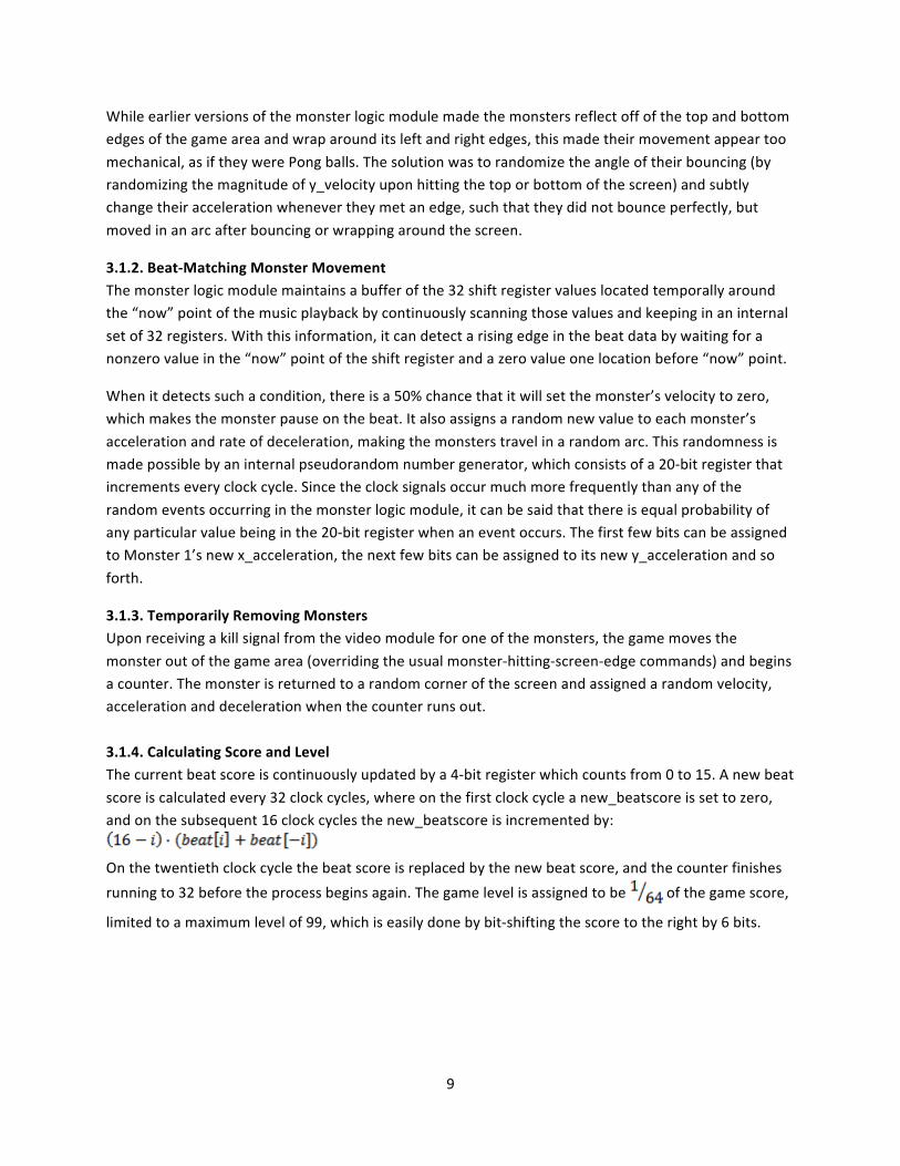
While earlier versions of the monster logic module made the monsters reflect off of the top and bottom edges of the game area and wrap around its left and right edges, this made their movement appear too
mechanical, as if they were Pong balls. The solution was to randomize the angle of their bouncing (by randomizing the magnitude of y_velocity upon hitting the top or bottom of the screen) and subtly change their acceleration whenever they met an edge, such that they did not bounce perfectly, but
moved in an arc after bouncing or wrapping around the screen.
3.1.2. Beat‐Matching Monster Movement The monster logic module maintains a buffer of the 32 shift register values located temporally around the “now” point of the music playback by continuously scanning those values and keeping in an internal
set of 32 registers. With this information, it can detect a rising edge in the beat data by waiting for a nonzero value in the “now” point of the shift register and a zero value one location before “now” point.
When it detects such a condition, there is a 50% chance that it will set the monster’s velocity to zero, which makes the monster pause on the beat. It also assigns a random new value to each monster’s
acceleration and rate of deceleration, making the monsters travel in a random arc. This randomness is made possible by an internal pseudorandom number generator, which consists of a 20‐bit register that increments every clock cycle. Since the clock signals occur much more frequently than any of the
random events occurring in the monster logic module, it can be said that there is equal probability of any particular value being in the 20‐bit register when an event occurs. The first few bits can be assigned to Monster 1’s new x_acceleration, the next few bits can be assigned to its new y_acceleration and so
forth.
3.1.3. Temporarily Removing Monsters Upon receiving a kill signal from the video module for one of the monsters, the game moves the
monster out of the game area (overriding the usual monster‐hitting‐screen‐edge commands) and begins a counter. The monster is returned to a random corner of the screen and assigned a random velocity, acceleration and deceleration when the counter runs out.
3.1.4. Calculating Score and Level The current beat score is continuously updated by a 4‐bit register which counts from 0 to 15. A new beat
score is calculated every 32 clock cycles, where on the first clock cycle a new_beatscore is set to zero, and on the subsequent 16 clock cycles the new_beatscore is incremented by:
On the twentieth clock cycle the beat score is replaced by the new beat score, and the counter finishes
running to 32 before the process begins again. The game level is assigned to be of the game score,
limited to a maximum level of 99, which is easily done by bit‐shifting the score to the right by 6 bits.

10
3.2. Gun Module The internal structure of the gun module is shown below:
Figure 3: Internal Structure of the Gun Module
The gun module performs the following functions:
• Communicating with the Analog‐to‐Digital Converter (AD574) to obtain the latest light‐level reading from a phototransistor and sending this reading to the video module.
• Raising the fire_enable signal based on inputs from the trigger and the fire mode toggle switch.
• Activating the solenoid to simulate recoil whenever the gun is fired.
3.2.1. Communicating with the Analog‐to‐Digital Converter The analog‐to‐digital converter (ADC) receives the output of a phototransistor which has been amplified by an actively‐loaded negative‐feedback cascode amplifier and an op amp to greatly increase its
response speed. This circuit can be seen below:
Figure 4: High‐Speed Phototransistor Amplifier and ADC Communication
The ADC is in 8‐bit “stand alone” mode where it can be controlled by a single signal (r_cbar, as described
in [6]) and the signal is raised and lowered with the correct timing by the ADC Control submodule. This is
11
implemented with an 11‐bit loop counter which increments every clock cycle. When the counter is below 2000, r_cbar is high, otherwise it is low. This provides the correct timing to get a new reading
from the ADC at 20KHz, which is sufficient for this implementation. 3.2.2. Raising the fire_enable signal
The fire_enable signal is raised for one clock cycle on the rising edge of the trigger input. This rising edge is found by storing the trigger value from the previous clock cycle in a register and comparing it to the current trigger value. If the previous trigger value was low and the current trigger value is high, the
trigger has just been pressed. Turning on the Fire Mode Toggle Switch puts the gun into automatic mode by making it ignore the previous trigger value and fire as long as the reload time is over.
3.2.3. Activating the solenoid The solenoid consumes a large amount of current (over 1A), and as such, it is powered by an external wall wart. A common emitter transistor amplifier is used to amplify the digital output of the FPGA to
sufficiently high voltage so that it is able to control the power MOSFET which channels current to the solenoid. When the solenoid fires, it produces a burst of electrical noise that renders the phototransistor temporarily unreliable. To overcome this problem, a delay counter waits for the hit detection algorithm
to be performed before the solenoid fires. This counter also inserts a reload time after the solenoid has fired to prevent its noise from interfering with the next hit detection.
12
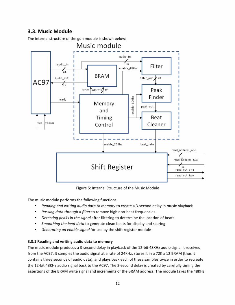
3.3. Music Module The internal structure of the gun module is shown below:
Figure 5: Internal Structure of the Music Module
The music module performs the following functions:
• Reading and writing audio data to memory to create a 3‐second delay in music playback
• Passing data through a filter to remove high non‐beat frequencies • Detecting peaks in the signal after filtering to determine the location of beats • Smoothing the beat data to generate clean beats for display and scoring
• Generating an enable signal for use by the shift register module 3.3.1 Reading and writing audio data to memory
The music module produces a 3‐second delay in playback of the 12‐bit 48KHz audio signal it receives from the AC97. It samples the audio signal at a rate of 24KHz, stores it in a 72K x 12 BRAM (thus it contains three seconds of audio data), and plays back each of these samples twice in order to recreate
the 12‐bit 48KHz audio signal back to the AC97. The 3‐second delay is created by carefully timing the assertions of the BRAM write signal and increments of the BRAM address. The module takes the 48KHz
13
ready signal from the AC97, and converts it into a 48KHz enable signal that is high for one clock cycle and also increment a counter. Whenever this 48KHz counter’s last bit is 1, the write signal to the BRAM
is asserted high for one cycle. This causes the current audio input to be written into memory. The address of the BRAM is then incremented immediately, and the value of write returns to 0. Thus, on the next clock cycle, the music module outputs the value read from the next address on the BRAM and
continues to do until the next write assertion. This creates a 3‐second delay, since the music module must cycle through all 72K addresses at a rate of 24KHz of the BRAM before it can return to read and output the same audio sample that was just written.
3.3.2 Passing data through a filter The music module also performs the important function of beat detection. For the purposes of the
project, a beat is defined to be an unusually large signal in frequencies of 100Hz or lower. The 12‐bit audio signal is converted from a signed signal to a positive one by adding a 1 to the leading bit. It is then sent through a low‐pass filter. The filter is a 63‐tap finite impulse response filter that attenuates any
signals above 100Hz. Using 63 stored 10‐bit fixed point coefficients and a buffer of the last 63 audio samples, the filter performs a convolution by multiplying and summing pairs of these values over 64 clock cycles to give a 22‐bit result, beginning each time the 48KHz enable signal is asserted.
3.3.3 Detecting peaks in the signal The upper 12‐bits of the of the filter output are passed to the peak detector. The peak detector
downsamples filter_out using an 800Hz enable signal from the timing control submodule. This 800Hz enable signal is created by using a counter that rolls over every 60 high assertions of the 48KHz enable
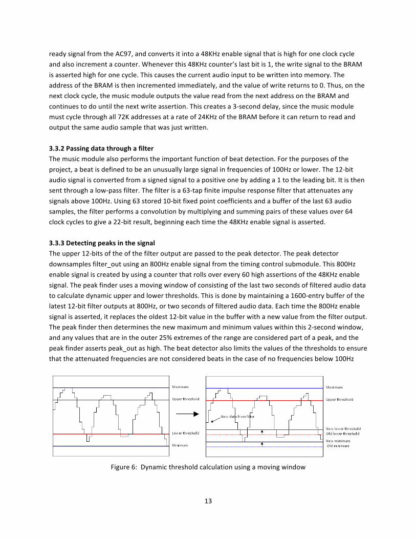
signal. The peak finder uses a moving window of consisting of the last two seconds of filtered audio data to calculate dynamic upper and lower thresholds. This is done by maintaining a 1600‐entry buffer of the latest 12‐bit filter outputs at 800Hz, or two seconds of filtered audio data. Each time the 800Hz enable
signal is asserted, it replaces the oldest 12‐bit value in the buffer with a new value from the filter output. The peak finder then determines the new maximum and minimum values within this 2‐second window, and any values that are in the outer 25% extremes of the range are considered part of a peak, and the
peak finder asserts peak_out as high. The beat detector also limits the values of the thresholds to ensure that the attenuated frequencies are not considered beats in the case of no frequencies below 100Hz
Figure 6: Dynamic threshold calculation using a moving window

14
3.3.4 Smoothing the beat data The output of the peak finder is then sent to beat data, which uses a simple algorithm to clean up the
peak data and convert it into solid beats of sufficient length for the player to time themselves to. The beat cleaner asserts beat_data as high on the first rising edge of peak_out it sees, and also starts a countdown of 63 cycles at 800Hz. The countdown can be extended so that it lasts at least as long as the
peak continues. While the countdown is still active, the beat cleaner will continue to assert a high on beat_data. This guarantees a beat lasts either 80 milliseconds or for the duration of the peak.
If a new peak occurs within 15 cycles of the countdown’s end, it is reset to 15, which allows the beat detection to determine that any large oscillations within 2 milliseconds of the beat in the audio signal are also part of the same beat, and thus the beat should be extended by continuing to assert beat_data
as high. Once the countdown runs out, a second countdown of 31 cycles begins, which tells the beat cleaner to ignore any further peaks within 4 milliseconds of the beat and reset the second countdown. This allows the beat detector to ignore any further oscillations if a low frequency is sustained for a long
period. 3.3.5 Generating an enable signal
The music module’s memory and timing control submodule provide a 200Hz enable signal to the shift register module. This enable signal is generated by counting the number of times the 800Hz enable signal has risen. When the 200Hz counter reaches a value of 3, it is rolls over at the 800Hz enable signal
is high for one clock cycle.
3.4. Shift Register Module The shift register module performs the following functions:
• Storing the last four seconds of beat data by writing newly‐generated beat detection output into the lowest bit of a register and moving the values in the remaining bits up by one.
• Providing beat data access to the rest of the game logic based on the values given by the video and monster logic modules
3.4.1. Storing the last four seconds of beat data The shift register module stores the 800 most recent values of 1‐bit beat detection data sampled at 200Hz in an 800‐bit wide register. The module uses the 200Hz enable signal generated by the music
module as its clock. Whenever this signal is asserted, the lower 799 values contained in the register are shifted up by one bit. The module simultaneously samples the 1‐bit 800Hz beat data output by the music module, and stores this value in the lowest bit of the register. Thus, the location of any beat
datum in the register corresponds to the time at which it was generated. A value in bit 0 is the most recently produced, a value in bit 599 was produced three seconds ago, which corresponds to the “now” point, and a value in the bit 799 was produced four seconds ago.

15
3.4.2. Providing beat data access The shift register module also contains two asynchronous read ports, which allows the monster logic
module and the video modules to read any beat data from the previous four seconds. Each port consists of a 10‐bit wide input and a 1‐bit output. The 10‐bit input of a port is used to select which bit of the register to access, and the corresponding 1‐bit beat data value will be returned on the output of the
same port.
3.5. AC97 Module The AC97 module was designed and written by the 6.111 staff. The only modification made to the 6.111 AC97 module for use in the game was to increase in the width of the digital audio input from 8 bits to 12
bits. The AC97 module performs the following functions: • Digitizing an analog signal from an audio source provided by the player to prepare for storage
and analysis by the music module.
• Changing a digital audio signal into analog based on the data provided by the music module. • Controlling the volume at which the stored audio data is played back at.
• Generating a 4 KHz signal which the music module uses to synchronize with the AC97 and to generate enable signals for internal use.
3.5.1. Digitizing an analog signal from an audio source The AC97 converts a monophonic audio signal into a 20‐bit digital signal at a rate of 48KHz. The upper 12 bits of this signal are sampled by the music module at a rate of 24KHz.
3.5.2. Changing a digital audio signal into analog The AC97 produces an analog audio signal from a 12‐bit 48 KHz digital audio signal. Each 12‐bit value is
shifted 8 places to the left to create the 20‐bit digital signal used for conversion to analog. 3.5.3. Controlling the volume
The AC97 module controls the volume of the analog output. The up and down buttons are used to adjust the volume over a range of 32 different values
3.5.4. Generating a 48KHz signal The AC97 module generates a 48KHz ready signal with a fifty percent duty cycle using an internal 24.576MHz crystal. This signal is asserted whenever both of the analog‐to‐digital and digital‐to‐analog
conversions are finished.

16
3.6. Video Module The video module is the master module that wraps up all the submodules that generate different aspects of the graphics.
3.6.1. Objects and Layers
There are three types of graphic objects: frame object, shootable object, and visual effect object. The frame objects include the music note, the scrolling beat bar, the edge lines, the scoreboard, the level board, and the numbers. The shootable objects include two moving monsters with animation. The
visual effect objects are start screen, hit effect, miss effect, and game over screen.
Objects are selected to shown on screen in different ways as the state of the game changes. This will be explained in details in the game state part. Typically, the visual effect objects are at the top layer while the shootable objects are in the bottom layer.
3.6.2.Video Overlay
The game contains 13 sources of images, which have to be integrated into a final image. We put out
objects into three layers: top, middle, and bottom. The top layer has the highest priority to show. It will block the images in the middle and bottom layers. The bottom layer has the least priority.
In our project, all graphic modules are designed to output zero(value is 24’h000000 ) at the positions
where they have nothing to show. So basically within each layer, we can just add up outputs from all the objects within that layer to product a single output for each layer. And we use condition statement to integrate all three layer’s output together.
3.6.3.Timing and Pipeline
The video overlay scheme requires adding several 24 bit numbers together. And generating read
address for BRAM requires multiplication. These calculations may have a large delay for our 40MHz video clock. So pipeline is used to solve the problem. We had a little problem with pipeline delays at the beginning when some part of the image is shown at the wrong position. We fixed it by making sure all
graphic modules have exactly the same numbers of delay. This means adding unnecessary delays to some modules. But it makes the pipeline easy to do. Finally, we had seven clocks latency in the video module.
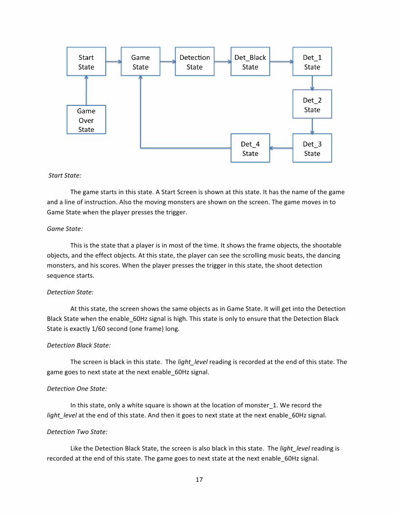
3.6.4.Game State
The game uses a FSM to control the video output. Different images are shown at different state. The
state diagram is shown below.
17
Start State:
The game starts in this state. A Start Screen is shown at this state. It has the name of the game and a line of instruction. Also the moving monsters are shown on the screen. The game moves in to
Game State when the player presses the trigger.
Game State:
This is the state that a player is in most of the time. It shows the frame objects, the shootable objects, and the effect objects. At this state, the player can see the scrolling music beats, the dancing monsters, and his scores. When the player presses the trigger in this state, the shoot detection
sequence starts.
Detection State:
At this state, the screen shows the same objects as in Game State. It will get into the Detection Black State when the enable_60Hz signal is high. This state is only to ensure that the Detection Black State is exactly 1/60 second (one frame) long.
Detection Black State:
The screen is black in this state. The light_level reading is recorded at the end of this state. The
game goes to next state at the next enable_60Hz signal.
Detection One State:
In this state, only a white square is shown at the location of monster_1. We record the light_level at the end of this state. And then it goes to next state at the next enable_60Hz signal.
Detection Two State:
Like the Detection Black State, the screen is also black in this state. The light_level reading is recorded at the end of this state. The game goes to next state at the next enable_60Hz signal.
18
Detection Three State:
Similar to Detection One State, a white square is shown at the location of monster_2. The light_level is recorded at the end of this state. And it goes to next state at the next enable_60Hz signal.
Detection Four State:
This is the last state in the shoot detection sequence. Nothing is shown on the screen. But
kill1_enable, kill2_enable, and miss_enable signals are generated in this state by comparing the recorded light_level values. The game goes back to Game State at the next enable_60Hz signal and ready for the next shoot.
Game Over State:
When the player ends the game, it goes into Game Over State. Only the frame objects and a
game over message are shown in this state. The game can be restarted by pressing reset button.
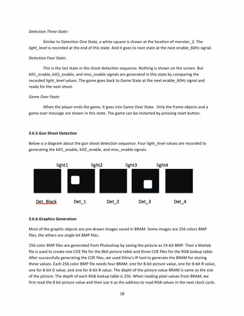
3.6.5.Gun Shoot Detection
Below is a diagram about the gun shoot detection sequence. Four light_level values are recorded to
generating the kill1_enable, kill2_enable, and miss_enable signals.
3.6.6.Graphics Generation
Most of the graphic objects are pre‐drawn images saved in BRAM. Some images are 256 colors BMP files, the others are single bit BMP files.
256 color BMP files are generated from Photoshop by saving the picture as 24‐bit BMP. Then a Matlab
file is used to create one COE file for the 8bit picture table and three COE files for the RGB lookup table. After successfully generating the COE files, we used Xilinx’s IP tool to generate the BRAM for storing these values. Each 256 color BMP file needs four BRAM: one for 8‐bit picture value, one for 8‐bit R value,
one for 8‐bit G value, and one for 8‐bit B value. The depth of the picture value BRAM is same as the size of the picture. The depth of each RGB lookup table is 256. When reading pixel values from BRAM, we first read the 8 bit picture value and then use it as the address to read RGB values in the next clock cycle.

19
Single bit BMP files are used to save memory space. We used Paint to convert pictures to single bit BMP file. Then we used Matlab to generate one COE file for the single bit value and saved it into BRAM.
When reading pixel values from BRAM, we only get one bit value 0 or 1. If it is 1, the pixel will be assigned a 24‐bit RGB color value. If it is 0, the pixel will be assigned to 0.
3.6.7.Generating the BRAM Read Address
To read from BRAM, we need to generate the correct read address. Most of my modules use similar methods for this. I will use the monster module as an example to shown the calculation process. There
are four steps:
1. Calculate the local location: hcount_diff, vcount_diff
hcount_diff and vcount_diff means how far the pixel is into the picture.
hcount_diff = hcount – x;
vcount_diff = vcount –y;
2. Multiply the vertical depth of the current pixel location by the width of the picture and add to the horizontal local location
addr = hcount_diff + (vcount_diff * width);
3. Read from picture BRAM using the address above
monster m1(addr, clock, picture_value);
4. Read from RGB lookup tables using the picture value above as address
monster_red mr1(picture_value, clock, R‐value);
monster_green mg1(picture_value, clock, G_value);
monster_blue mb1(picture_value, clock, B_value);
3.6.8. Monster Submodule The monster sub‐module generates the pixel for moving monster. Two slightly different pictures are used for each monster, shown below. Both pictures are 256 colors BMP. So there’s totally 8 BRAM
created for this monster module. The detail about reading from BRAM is explained in the Generating the BRAM Read Address part.
The two pictures are switched to be displayed every half second to make the animation. A 6bit counter and the enable_60Hz signal control this timing.

20
Figure 7: Monster graphics
3.6.9. Music Note Submodule The music note submodule generates the pixels for the jumping music note at the top left corner of the
screen, which indicates that music is playing. The music note is generated from a single bit BMP file as shown below. The position of the music note changes every second, which makes it look like jumping. Also the color of the music note rotates from seven different colors.
Figure 8: Music note graphic
3.6.10. Beat Bar Submodule The beat bar submodule generates the scrolling music beat bar at the top of the screen. As the bar moves from left to right, its color gets brighter. After it passes the present line, the bar turns grey and
black. To archive the color changing effect, we use a pre‐drawn 800 x 1 picture as the color map for each hcount value. This picture is stored in BRAM as three 8‐bit RGB color tables. Their read address is hcount. The beat bar submodules gets the music beat information from shift register module. It only
shows the color at a pixel if there is a beat at that position in the shift register.
Figure 9: Beat bar graphic
3.6.11. Edge Submodule The edge submodule generates the pixels for the two green edge lines on the screen. Each edge line is
800 pixels long. To save memory space, we only use a 32 x 10 picture to generating the edge line by repeating it. We do this by using the last 5 bits of hcount as the local horizontal location.

21
Figure 10: Edge graphic
3.6.12. Score Submodule The score submodule generates the scoreboard at the left bottom corner of the screen. The level submodule generates the level at the right bottom corner of the screen. They both read 256‐color
pictures from the BRAM.
Figure 11: Score and level graphics
3.6.13. Numbers Submodule The numbers submodule generates the pixels for the score number and level number. Ten pre‐drawn pictures are saved in the BRAM as 1‐bit BMP files. Each picture is one number from 0 to 9, as shown
below.
Figure 12: Numbers graphics
For each clock cycle, only one pixel value is needed, so we only need one BRAM for each of the numbers since one picture is shown several times on the screen. The pixel value is generated in three steps:
1. Determine the position of the number from hcount, vcount. Store the value of that number into
number_value. 2. Generate the read address for that number and pass it to all 10 number BRAMs. 3. Using a case statement on number_value to choose the right output from 10 number BRAMs as
the final output.
3.6.14. Hit Submodule and Miss Subodule The hit submodule and miss submodule generate the images for hit and miss effect. They read pixels values from two 150 x 100 single bit BMP file saved in BRAM. To save memory space, the images are
magnified as 300 x 200 pictures on screen. This is done by removing the last bit of the hcount_diff and vcount_diff when generating the read address for BRAM.
Figure 13: Hit and miss graphics

22
3.6.15. Start Submodule and Game Over Submodule
The Start submodule and Game Over submodule generate the images for the start screen and game over screen. Like hit module and miss module, they also use 150 x 100 single bit BMP file and enlarge by two when shown on screen.
Figure 14: Start and game over graphics
23
4. Testing 4.1. Testing the Monster Logic Module Basic elements of the monster logic module were tested in simulation. These include:
• Incrementing of position and velocity after every video frame
• Incrementing of score and game level • Change of monster position, velocity and acceleration after every successful hit
The monster logic was then tested extensively using a primitive, fast‐compiling version of the video
module to display the monster movement. This allowed for fine‐tuning of the monsters’ movement and extensive experimentation with various methods of making the monsters appear to dance with the beat
of the music. 4.2. Testing the Gun Module
The gun module did not need to be tested in simulation as its compile time was fairly short. Instead, successive iterations of the gun module were compiled and tested on the FPGA, with its outputs being connected to the in/out pins of the FPGA and observed using the oscilloscope and logic analyzer.
4.3. Testing the Music Module Certain elements of the music module went through testing before being implemented as part of the
game. The filter submodule tested as part of previous lab, but in a version that used fewer taps. The efficacy of the peak finder was tested in simulation using scaled sine wave data as an input signal. However, this proved to be insufficient because the AC97’s audio signal was signed, and furthermore,
not centered about zero, which later caused much difficulty in determining the locations of peaks in practice. The generated enable signals were tested using the logic analyzer.
4.4 Testing the Video Module The video module was tested by supplying the logic with dummy values for the shift register module and monster logic module inputs.

24
5. Conclusion The project was implemented with great success, resulting in the timely creation of a functional, entertaining and aesthetically‐pleasing video game that fulfilled the original objectives:
• The player can use a light gun to fire at two moving targets displayed on the screen.
• The background music supplied by an outside audio source is played back in synchronization with the rest of the game
• Beat detection is performed on the music in real time and displayed across the top of the
screem. • The player can earn points by shooting the targets in time or nearly in time with the beats.
In addition, several other additional features were implemented, including (but not limited to) starting and ending screens for the game, animation of the monsters, the ability to adjust the volume of the audio, and an increase difficulty by changing the monster movement parameters.
6. Future Improvements 6.1. Phototransistor Optics One significant improvement would be the use of lenses to focus light from the screen onto the phototransistor. This would greatly increase the amount and accuracy of light detected, reducing noise
and allowing the phototransistor circuit to be run at a much higher speed. An interesting use of this increased speed would be to replace the hit detection algorithm with one which only uses a single video frame (as described in [4]), where the whole screen is filled with white. As the white pixels are drawn
from left to right, top to bottom by the scanning signal from the FPGA, the game can record the exact moment when a pixel is drawn in front of the gun and the exact direction of the gun barrel can be determined.
6.2. Visible Wavelength Phototransistor This project was designed exclusively for CRT monitors and would not work on LCD monitors, as LCD
monitors emit a uniform intensity of infrared light regardless of the color on the screen. The game could be made to work on LCD monitors as well if we were to use a visible wavelength phototransistor instead, which we were unable to obtain due to their rarity and cost.
6.3. Sound Effects One planned feature which was not implemented in this game was sound effects to indicate a successful
target hit. This feature was removed due to a shortage of BRAM to house the sound effects, but it is conceivable that the sound effects (and other space‐consuming elements such as graphics) could be procedurally generated (as suggested in [5]) in real‐time to save space.

25
6.4. Improved Beat Detection The beat detection algorithm was effective only over a small range of audio input volumes. This
occurred because the high frequency signals were only attenuated and not completely removed. In order to prevent the beat detector from recognizing these signals as beats, the upper and lower thresholds had dynamically calculated minimum and maximum values. This also had the effect of
causing the beat detector to ignore valid peaks in low frequencies if they were scaled down too far by lowering the overall volume of the audio input data. In addition, the audio signal would be clipped if the volume of the analog audio input exceeded what the AC97 could process. This resulted in the peak
finder being unable to determine the true maximum and minimum values, and thus it would incorrectly determine too much of the signal to be a beat. One approach to address these problems would be to use a fast Fourier transform instead of a low‐pass filter, which would allow the algorithm to consider
only the relevant frequencies, and ignore undesired frequencies altogether.
7. References
1. Lab #4, 6.111 Fall 2009 website, 19 Oct 2009: http://web.mit.edu/6.111/www/f2009/index.html 2. Lab #5, 6.111 Fall 2009 website, 26 Oct 2009: http://web.mit.edu/6.111/www/f2009/index.html 3. C. Terman, G. Hom, A. Lerer, “6.111 Fall 2009 Course Notes”, MIT EECS Department, 2009.
4. How Stuff Works: How Does The Light Gun For A Video Game Work, 19 Oct 2009: http://electronics.howstuffworks.com/question273.htm
5. Procedural Graphics: An Introduction, 10 Dec 2009:
http://in4k.untergrund.net/index.php?title=Procedural_Graphics_‐_an_introduction 6. AD574A* Complete A/D Converter Datasheet, 10 Dec 2009:
http://www.analog.com/static/imported‐files/data_sheets/ad574a.pdf
7. LM4550 AC ’97 Rev 2.1 Multi‐Channel Audio Codec Data Sheet, 10 Dec 2009: http://web.mit.edu/6.111/www/f2009/handouts/labs/LM4550.pdf