6.1 Introduction - University of Pretoria
36
6-1 CHAPTER 6 DERIVATION OF MECHANISTIC STRUCTURAL DESIGN CRITERIA 6.1 Introduction This chapter addresses the derivation of the design criteria for the mechanistic design of surface mine haul roads. The structural performance categorisation introduced previously is used as a guide to the efficacy of the various existing haul road designs. Stresses and strains generated from the multi-layer elastic solution for the particular road test section are then compared with the structural performance categorisation to established suitable design criteria. Construction material elastic moduli are assessed in terms of both the TRH14 classification and the DCP derived empirical relationship whereby suitable moduli for the various classes of granular materials used in haul road construction are derived. The catologue of modulus values facilitates the adoption of the technique without the need for separate tests to determine suitable modulus values, unless construction materials differ significantly from those analysed. An optimum structural design is then sought through consideration of the response of each pavement layer to the applied loads and the limiting design criteria previously assessed. 6.2 Derivation of Limiting Design Criteria Two design criteria were proposed with which to assess the structural performance of mine haul roads, namely factor of safety (FOS) for the two uppermost layers and vertical compressive strain for each layer below the top layer. As discussed in Chapter 5, the FOS does not appear to correlate with the structural performance classification. Mine test site roads exhibiting good structural performance do not necessarily exhibit correspondingly high layer FOS values, the latter being a function of the ultimate strength of each layer, which is normally not mobilised, the depth of the wearing course layer an the choice of depth at which the FOS is calculated. It is thus concluded that the FOS design criteria in the upper layers
Transcript of 6.1 Introduction - University of Pretoria
6-1
CHAPTER 6
DERIVATION OF MECHANISTIC STRUCTURAL DESIGN CRITERIA
6.1 Introduction
This chapter addresses the derivation of the design criteria for the mechanistic design of
surface mine haul roads. The structural performance categorisation introduced previously
is used as a guide to the efficacy of the various existing haul road designs. Stresses and
strains generated from the multi-layer elastic solution for the particular road test section are
then compared with the structural performance categorisation to established suitable design
criteria.
Construction material elastic moduli are assessed in terms of both the TRH14 classification
and the DCP derived empirical relationship whereby suitable moduli for the various classes
of granular materials used in haul road construction are derived. The catologue of modulus
values facilitates the adoption of the technique without the need for separate tests to
determine suitable modulus values, unless construction materials differ significantly from
those analysed. An optimum structural design is then sought through consideration of the
response of each pavement layer to the applied loads and the limiting design criteria
previously assessed.
6.2 Derivation of Limiting Design Criteria
Two design criteria were proposed with which to assess the structural performance of mine
haul roads, namely factor of safety (FOS) for the two uppermost layers and vertical
compressive strain for each layer below the top layer. As discussed in Chapter 5, the FOS
does not appear to correlate with the structural performance classification. Mine test site
roads exhibiting good structural performance do not necessarily exhibit correspondingly high
layer FOS values, the latter being a function of the ultimate strength of each layer, which is
normally not mobilised, the depth of the wearing course layer an the choice of depth at which
the FOS is calculated. It is thus concluded that the FOS design criteria in the upper layers
6-2
is not applicable to haul road design. Other design criteria may be more appropriate,
particularly the vertical strain criterion. In the absence of any definitive criterion for the
wearing course, a 200mm layer of compacted (95-98 % Mod. AASHTO) good quality
wearing course gravel would appear most appropriate, based on those mine sites wearing
course layers exhibiting adequate structural performance.
Figure 6.1 relates the vertical compressive strain measurements taken at each mine site; those
mine sites exhibiting poor performance and an associated excessive deformation/maximum
deflection were seen to be associated with large vertical compressive strain values in one or
more layers. When the maximum verticat' strain is analysed in conjunction with the
structural performance of the road (based on the product of performance index and daily
traffic repetitions) as can be seen in Figure 6.2, as the structural performance index of the
road is increased at a particular level of traffic volume, the maximum recorded strains in the
pavement layers then decrease. Similarly, for a given performance index, increasing traffic
volumes can be associated with lower maximum strain (and thus deformation) values. By
plotting a maximum strain envelope (for a minimum satisfactory performance index of 7),
the maximum allowable strain recommended for various traffic volumes and required
performance levels is given by Equation [6.1];
where emax
KT
I
=
=
e = exp(8,2 -O,OO7.KT.1) max
maximum allowable vertical compressive microstrain
daily tonnage hauled on road (kt)
performance index (1-10)
[6.1]
Since the majority of mines' monthly tonnage lies in the region of 300kt, and using a
performance index of 7 it is evident that an upper limit of 2000 microstrain should be placed
on layer strain values in this case. A similar value is adopted for public road construction
(Maree and Freeme, 1981) applicable to similar materials as are used in mine haul road
construction, together with a strain reduction for increased standard axle repetitions and
maximum allowable deformation. The Asphalt Institute (1973) design method for airport
pavements subject to loads up to 1580kN recommend a maximum subgrade strain of between
2548-1422 microstrain for between 100 and 1x10⁶ repetitions. The 2000 microstrain limit

6-3
VERTICALCSTBAIN D1ESlGN CnlTERIA Krler- olilery a rf •• ree 8 tea Vertlaal atraln (mlcroatralna)
8000 .............................................................................................................................................................................................. ~ ........... .
8000 .......................................................... <....................... . ................................................................................................................... .
4000
2000
12 I
Mine alte I Layer number
sXEeT~~:Jid'la~~~IRGr~l(l" a~l"tE.a\~a Vertloal atraln (mloroatralna)
8000 ............................................................................................................................................................................................................ ..
8000 ............................................................................................................................................................................................................. .
4000 ............................................................................................................................................................................................................. .
2000
I
Mine alte : Laye, number
VERTICAL STRAIN DESIGN CRITtERIA ~ew vaarcon ery all Inree 8r1e8
Vertloal atraln (mloroatralna)
8000 ................................................................................................................................................ ~ .......................................................... ..
8000
4000
Mine alte I Layer number
Figure 6.1 Vertical Strain Measurements at all Mine Sites

6-4
VERTICAL COMPRESSIVE STRAIN VARIATION WITH TRAFFIC AND PERFORMANCE·
For all mine altea and pavement layera
Vertical compressive mlcrostraln (x1000) 9~------------------------------------------------~
x 8 ~ ..... 2,6 ................................................. · .................................................................................................................... .
7 1-................................................................................................................................................................................. ..
6 ~ ................................................................................................................................................................................. .
6 ~ ................ ~.1 ................................................ ·· .. ····· .. · .. ····· .... ···· .. ·· .. ·· .. ·· .. ··· .. ··)(·4·· .... ··· .... ··· ..................................... . 4 ~············· .. ·:!··1········ .. · .. · .. ···················· ........................................................................................................................ .
4 : ::::::~;,~~::::: .......... ::~.~:::::::::::::::::::::::::::::::::::::::: ................ :::~:::::::::::::::::::::::::::::::::::::::::::::::::::::::::~::: 1 W x 8 1 1-................................. 4 ........................ 8 ............................................ i!-..... +'4 ............................ I:I*.lj ......... 7' ..
o I I I II I I
o 20 40 60 80 100 120 140 180 traffic volume performance Index*
Pavement layer
x Layer 2 + Layer a * Layer. - Max atraln envelope Number. rel8r. to layer performance Index
• Product of performance Index and dally tonnage hauled (kt)
Figure 6.2 Maximum Vertical Compressive Strain Variation with Traffic and Structural Performance Index
is thus motivated as a design criteria for mine haul roads, based on typical traffic volumes
and required performance index. Where traffic volumes are lower and/or poor structural
performance is acceptable (short term roads) the maximum strain limit can be accordingly
reduced following Equation [6.1].
6.3 Selection of Effective Elastic Modulus Values
The strains induced in a pavement are a function of the effective elastic modulus values
ascribed to each layer in the structure. In order to facilitate mechanistic design of mine haul
roads, some indication of applicable moduli values are required for the practical application
of the method. This was achieved by considering the individual layer modulus values
generated by the mechanistic analysis of existing pavements and comparing these values to
established modulus values and the associated material classification.

6-S
For each test site analysed, each layer exhibited a range of effective elastic modulus values,
dependant on the specific material used for road construction. Current data relating the range
of moduli for granular materials, classified following CSRA TRH14 guidelines (Committee
of State Road Authorities, 1985) is presented in Table 6.1. A classification for (amongst
other materials) untreated gravel materials and dumprock is proposed in CSRA TRH 14. In
all, six material groups are recognised, in descending order of strength and quality for
roadbuilding purposes, from a 01-03 (high quality graded crushed stone), G4-G6 (natural
gravels), 07-010 (gravel soil) to (DR) dumprock. Classification is based on material
grading, Atterberg limits, CBR, swelling and field compaction characteristics. A summary
of the applicable material characteristics for 01 to 010 and dumprock materials is presented
in section 6.3 as they apply to haul road construction.
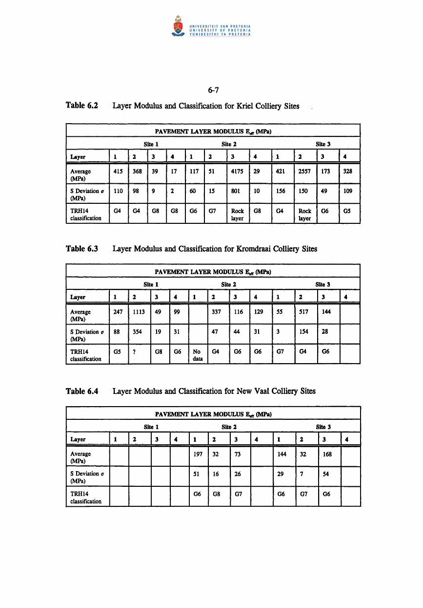
Tables 6.2-6.4 summarise the moduli values and associated classification for the materials
used in each site pavement construction whilst Figure 6.3 presents the information
graphically. As can be seen the modal material classification (ignoring in-situ material) is
that of a 04-06 gravel or low quality gravel where local mine ferricrete is used. The
imported material used in the New Vaal construction does not differ significantly from this
classification. It would therefore seem prudent to adopt blanket modulus values for these
material types. A modulus range of 150-200MPa is proposed for 04-06 gravels when used
in wearing course and 7S-100MPa for the same material when used in a base or sub-base
layer. These values are slightly lower than the average values reported by SARB (1993),
thereby accommodating local deviations from the standard material, compaction, stress
softening effects, the presence of water and poor support from sub-grade materials. Values
for the moduli of the in-situ sub-grade material are very much site and material ~pecific and
range from 17MPa to 388MPa and often exhibit stress softening. The use of DCP derived
CBR values as outlined in section 4.2.4 may provide the most tractable approach in
ascertaining suitable modulus values for this material. Data in Tables 6.1 and 6.S may be
used in conjunction with the CBR data to determine modulus values for these poorer quality
(07-010) sub-grade materials.
The use of the DCP to investigate the structural performance of haul roads has been limited
to the generation of balance profiles, CBR values for each layer and seed modulus for the
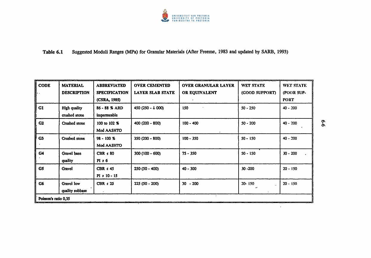
Table 6.1 Suggested Moduli Ranges (MPa) for Granular Materials (After Freeme, 1983 and updated by SARB, 1993)
CODE MATERIAL ABBREVIATED OVER CEl\IENTED OVER GRANULAR LAYER WET STAT .. : \v..:-r STATI~ .. DESCRIPTION SPECIFICATION LAYER SLAB STATE OR EQUIVALENT (GOOD SUI'PORT) (POOR SUP-
(CSRA, 1985) I'()R ...
GI High quality 86- 88 ~ ARD 450 (250 - .1. 000) 150 50 - 250 40 - 200
I crushed stone impermeable
G2 Crushed stone 100 to 102 ~ 400 (200 - 800) 100 - 400 50 - 200 40 - 200 ,I
0\
'" I ModAASHTO
. G3 Crushed stone 98 - 100 " 350 (200 - 800) 100 - 350 50 - ISO 40 - :!OO
ModAASHTO . G4 Gravel base CBR (80 300 (100 - 600) 75 - 350 SO - ISO 30 - 200
quality PI ~ 6
G5 Gravel CBR (45 250 (50 - 400) 40 - 300 30 -200 20 - ISO
PI ,. 10 - IS
GG o ravel low CBR oJ 2S 225 (SO - 200) 30 - 200 20- 150 .. 20 - 150 .. ' quality subbase
Poisson's rado 0,35
6-7
Table 6.2 Layer Modulus and Classification for Kriel Colliery Sites
PAVEMENT LAYER MODULUS E. (MPa)
Site 1 Site 2 Site 3
Layer 1 2 3 4 1 2 3 4 1 2 3 4
Average 415 368 39 17 117 51 4175 29 421 2557 173 328 (MPa)
S Deviation (1 110 98 9 2 60 15 801 10 156 150 49 109 (MPa)
TRH14 G4 G4 G8 G8 G6 G7 Rock G8 G4 Rock G6 G5 classification layer layer
Table 6.3 Layer Modulus and Classification for Kromdraai Colliery Sites
PAVEMENT LAYER MODULUS E. (MPa)
Site 1 Site 2 Site 3
Layer 1 2 3 4 1 2 3 4 1 2 3 4
Average 247 1113 49 99 337 116 129 55 517 144 (MPa)
S Deviation (1 88 354 19 31 47 44 31 3 154 28 (MPa)
TRH14 G5 '1 G8 G6 No G4 G6 G6 G7 G4 G6 classification data
Table 6.4 Layer Modulus and Classification for New Vaal Colliery Sites
PAVEMENT LAYER MODULUS Eerr (MPa)
Site 1 Site 2 Site 3
Layer 1 2 3 4 1 2 3 4 1 2 3 4
Average 197 32 73 144 32 168 (MPa)
S Deviation (1 51 16 26 29 7 54 (MPa)
TRH14 G6 G8 G7 G6 G7 G6 classification

6-8
Table 6.5 Suggested Modulus of Sub-grade Materials (after SARB, 1993)
CODE
07
G8
09
GIO
SOAKED MATERIAL EFFECTIVE E-MODULUS
CDR
1- IS
" 10
,,7
~3
(l\fPa)
"'ET STATE DRY STATf;
Gravtl--soil 20 - 120 30 - 200
Gravel-soil 20 -90 .30 - 180
Oravel--soil 20 -70 30 - 140
Gravel-soil 10 - 45 20 - 90
PAVEMENT LAYER ELASTIC MODULUS CLASSIFICATION
All mine alte layera
Elaatlc modulua (MPa) 800~----------------------------------------~
600 .......................................................................................................................................................................... .
400 ............................................................................................................................................................... ..
300 ..... e .................................................................................................................................................. . 200 ...
100 ....
o 04 96 08 07 08
TRH14 claaalfication of matarlal
Figure 6.3 Range of Elastic Modulus Values Encountered for Various Material Classifications

6-9
multi layer elastic analysis. It has been shown in section 4.2.4 that the balance profIle has
limited application in the design of mine haul roads since one of the most efficient and
structurally sound designs incorporates a rock layer at a shallow depth resulting in a poorly
balanced shallow strength profile. In general terms the strength balances to be avoided are
those of inverted structures and, to a lesser extent, poorly balanced deep. Both are
associated with excessive vertical strains in the pavement.
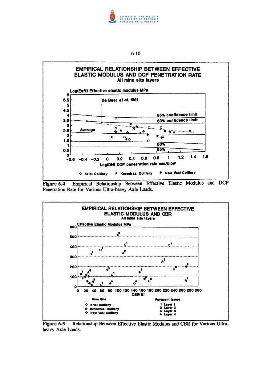
The empirical relationship used to determine the seed modulus for the mechanistic model
[Equation 5.2] has been reanalysed in the light of the final solutions for the layer modulus
and the DCP penetration rate values (DN) as shown in Figure 6.4. Some trend is evident
but the confidence limits calculated for the relationship are large and a solution within 80%
confidence extends over two decades. The empirical relationship derived in this study for
a 430kN wheel load and 630kPa contact stress is given in Equation [6.2].
log(E,.u> = 2,281-0,3138(1og(DN» [6.2]
The associated standard error of estimate is 0,487 and R2=68%. Data pertaining to the
analysis is given in Appendix D4.
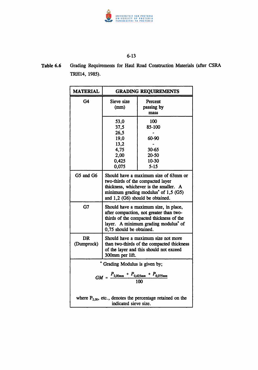
It is difficult to motivate for the existence of a direct relationship between effective elastic
modulus and DCP penetration rate due to the very different testing techniques employed to
derive different characteristic parameters for the same material (shear failure for DCP and
elastic response for MDD). This is evident when the effective elastic modulus is plotted
against the pavement layer CBR value derived from the DCP testwork, as shown in
Figure 6.5. Thus the relationship proposed above should be used with caution, bearing in
mind the limitations associated with its derivation.
6.4 Summary of Recommended Mechanistic Design Procedure
The optimal mechanistic structural design of a surface mine haul road embodies the selection
of target effective elastic modulus values for the construction materials available and the
6
6-10
EMPIRICAL RELATIONSHIP BETWEEN EFFECTIVE ELASTIC MODULUS AND DCP PENETRATION RATE
All mine site layers
Log(Eeff) Effective elastic modulus MPa
~ De Beer .t .~ 1991 :-'
,. i::-
--~ 96-1 confidence limit ..... ..... v SO-l confidence limit ~ ........................................... ~.
o 1 .............. 0 0 ~ Average ot1..eo" + .................. * .... i .. * .... ··· .......... ~ .... ~ • 0+0
'Y' '*rIP
l- n "- SO .. ,. .95" I • •
I I • • I
6.6 6
4.6 4
3.6 3
2.6 2
1.5 1
0.5 o - 0.8 - 0.4 - 0.2 0 0.2 0.4 0.6 O.S 1 1.2 1.4 1.8
Log(ON) DCP penetration rate mm/blow
o Krlel Colller1 '* Kromdraal Colller1 .. New Vaal Colliery
Figure 6.4 Empirical Relationship Between Effective Elastic Modulus and DCP Penetration Rate for Various Ultra-heavy Axle Loads.
EMPIRICAL RELATIONSHIP BETWEEN EFFECTIVE ELASTIC MODULUS AND CBR
All mine alte layere
800 Effective Elaatlc Modulua MPa
.2 500r-··· .... ·············· .. ······ .... ·· .. ················ .. ·· ........................................................................................... .
0' , 400 ~··· .. ·· .. ···· .. · .. ···· .... ·I .. · .......... ···· .. ·· .. ········ ...... · .... ·· ....................................... 9 .................................. .
4 0 2 o .. 300 ~ .................................................................................................................................................... . ,*'
8 200 r-.................................... ~ ......................... ·· .. · .... ·· .... · .. ······ ...... · .. ···· ............ ······· .. 8···· .. ·· .. + .... · ...... . 8" , 0
: '* , + 1 00 I-••••• i/!a.-................. --.-Q .... - ....... --... __ .-.-... ::2.-.-... -.---.----..... - ....... -.---.-
4 8 .8 4 4 oGi 02 *' ~8 0
4 t I I 9 I I • • J ~L O~~~~~~--~~----~~~~--~------~ o 20 40 80 80 100120 140 180 180200220240280280300
CBR( .. ) Mine 81te
o Krlel Colliery • Kromdraal Colliery + New Vaal Colliery
Pavement 'ayer. 1 Layer 1 2 Layer 2 3 Layer 3 4 Layer 4
Figure 6.S Relationship Between Effective Elastic Modulus and CBR for Various Ultraheavy Axle Loads.

6-11
placement of those materials such as to optimise their performance both as individual layers
and over the entire structure. Performance has been analysed in terms of minimum wearing
course thickness and compaction and the limiting design criteria of vertical strain in the base,
sub-base and sub-grade layers. In addition, of the various design options analysed at each.
mine test site, the inclusion of a rock layer immediately below the wearing course proffered
the structure increased resilience to the applied loads without recourse to excessive structural
thickness. These fmdings are examined as they appertain to the mechanistic structural design
of mine haul roads.
Materials available on site for the construction of roads is derived from borrow pits or the
pit itself. Borrow pit material comprises generally ferricrete and may be classified (following
TRHI4) as G4-G6. Material derived from in-pit working, typically sandstone parting, is
classified as dumprock (DR). Selection criteria for these materials are analysed in terms of
material grading, Atterberg limits, CBR, swelling and field compaction characteristics as a
precursor to assigning target effective elastic modulus values to the material.
All natural materials will display a degree of inherent variability and a certain percentage of
the population will exhibit poorer quality levels than those specified. TRH14 recommends
that not more than 10% of the materials should have a quality level below the specification
limit. These guidelines can be accepted for typical borrow pit material used in haul road
construction, although poor quality materials may exceed the 10 % limit. This deviation is
accomodated by adopting the lower-bound modulus values reported in the Tables 6.1 & 6.5.
Grading
Construction materials classified following TRH 14 should comply with the grading
requirements given in Table 6.6. Recommendations regarding the design of roads with these
materials (Freeme, 1983) limit G4-G5 to the road base and 06-G7 to the sub-base.
However, the mechanistic analysis of road performance indicates that a 04-05 gravel is
suitable for base and sub-base layers in haul road construction. CSRA draft TRH20 (The
Structural Design, Construction and Maintenance of Unpaved Roads), (Committee of State
Road Authorities, 1990) guidelines in regard to recommendations for material selection in

6-12
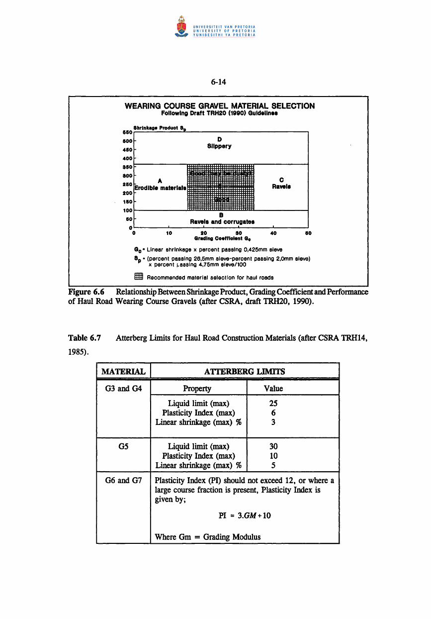
haul road construction are illustrated in Figure 6.4 in terms of the grading coefficient. This
value should range between 16 and 34. In addition, a maximum material size of 7S-100mm
is recommended together with oversize index (percent retained on 37,Smm sieve) of ::; 10%.
The assessment of haul road functionality will provide confrrmation of these
recommendations as regards the specific requirements of mine haul road users. The
remaining selection parameters are discussed in the following subsections.
Atterberg Limits
The Atterberg limits given in Table 6.7 apply to the soil fmes « 0,42Smm) of natural
gravels (04 and 05). In general, high plasticity material should be avoided due to the
associated stress softening effect as discussed in Chapter 5.3. TRII20 recommendations are
summarised in Figure 6.6 in which a shrinkage product value of between 100-365 (maximum
preferably <240) is used. This value incorporates both the quantity of fmes and the linear
shrinkage of the material, similar approximate values derived from TR1114 recommendations
for G4 and 05 materials are 90 and 150 respectively.
Bearing Strength and Swell
Bearing strength (7 day soaked CBR) and swell properties for typical construction materials
are given in Table 6.S. TR1120 recommendations are limited to a bearing strength of
CBR~ 15 at ~95% Mod AASHTO compaction after 4 days soaking, approximately
equivalent to a G6-G7 material.
Field Compaction
In \)rder to achieve the target effective elastic modulus values for the various categories of
materials available for construction, filed compaction requirements should also be considered.
These are given in Table 6.9, according to the pavement layer position of the particular
material. In all cases the moisture content of the various materials employed should be the
optimum for the compaction plant employed to ensure that during compaction, instability or
excessive movement of the material is avoided.
6-13
Table 6.6 Grading Requirements for Haul Road Construction Materials (after CSRA
TRH14, 1985).
MATERIAL
G4
G5 and G6
07
DR (Dumprock)
GRADING REQUIREMENTS
Sieve size Percent (mm) passing by
mass
53,0 100 37,5 85-100 26,5 -19,0 60-90 13,2 -4,75 30-65 2,00 20-50
0,425 10-30 0,075 5-15
Should have a maximum size of 63mm or two-thirds of the compacted layer thickness, whichever is the smaller. A minimum grading modulus· of 1,5 (G5) and 1,2 (06) should be obtained.
Should have a maximum size, in place, after compaction, not greater than twothirds of the compacted thickness of the layer. A minimum grading modulus· of 0,75 should be obtained.
Should have a maximum size not more than two-thirds of the compacted thickness of the layer and this should not exceed 300mm per lift.
• Grading Modulus is given by;
GM = P2,OOmm + PO,42Smm + PO,07Smm
100
where P2,oo, etc., denotes the percentage retained on the indicated sieve size.
6-14
WEARING COURSE GRAVEL MATERIAL SELECTION Following Draft TRH20 (1990) Guideline.
15150
1500
4S0
400
8150
800
2S0
200
110
100
8hrlnkage Produot 8D
I-
r... I-
10
o o
A ~.L • material.
,
10
D Slippery
C Ravel.
B Ravel. and corrugate.
I
20 80 40 Grading Coefflolent Go
Go· Linear shrinkage x percent passing O,425mm sieve
eo
8p • (percent passing 26,6mm sieve-percent passing 2,Omm sieve) x percent j:..asslng 4,76mm sleve/100
gm Recommended mater/al selection for haul roads
Figure 6.6 Relationship Between Shrinkage Product, Grading Coefficient and Performance of Haul Road Wearing Course Gravels (after CSRA, draft TRH20, 1990).
Table 6.7
1985).
Atterberg Limits for Haul Road Construction Materials (after CSRA TRH14,
MATERIAL ATTERBERG LIMITS
G3 and G4 Property Value
Liquid limit (max) 25 Plasticity Index (max) 6
Linear shrinkage (max) % 3
G5 Liquid limit (max) 30 Plasticity Index (max) 10
Linear shrinkage (max) % 5
G6 and G7 Plasticity Index (PI) should not exceed 12, or where a large course fraction is present, Plasticity Index is given by;
PI = 3.GM+I0
Where Gm = Grading Modulus

6-15
Table 6.8 CBR and Swell Properties for Haul Road Construction Materials (after CSRA
TRH14, 1985).
MATERIAL CDR AND SWELL PROPERTIES
03 and 04 Should have a CBR after soaking of not less than 80% at 98% Mod. AASHTO and a maximum swell of 0,2% at 100% Mod. AASHTO density
05 Should have a CBR after soaking of not less than 45 % at 95 % Mod. AASHTO and a maximum swell of 0,5 % at 100% Mod. AASHTO density
06 and 07 PROPERTY VALUE 06 07
Minimum CBR at 93 % Mod. 25 15 AASHTO density.
Maximum swell at 100 % Mod. 1,0 1,5 AASHTO density
Table 6.9 Field Compaction Requirements for Haul Road Construction Materials (after
CSRA TRH14, 1985).
PAVEMENT CONSTRUCTION RELATIVE COMPACTION LAYER MATERIAL
Base Natural gravel or gravel- 98% Mod. AASHTO (upper and lower) soils (selected ferricrete)
04-05 Compaction is continued until Dumprock (DR) movement under the roller is
negligible
Subbase Natural gravel or gravel- 95% Mod. AASHTO (upper and lower) soils (selected ferricrete)
05-06
Selected layers Natural gravel or gravel- 93 % Mod. AASHTO soils (selected ferricrete) 05-07
6-16
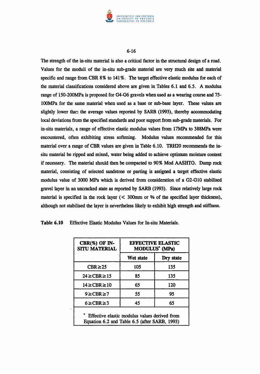
The strength of the in-situ material is also a critical factor in the structural design of a road.
Values for the moduli of the in-situ sub-grade material are very much site and material
specific and range from CBR 8 % to 141 %. The target effective elastic modulus for each of
the material classifications considered above are given in Tables 6.1 and 6.5. A modulus
range of 150-200MPa is proposed for G4-G6 gravels when used as a wearing course and 75-
l00MPa for the same material when used as a base or sub-base layer. These values are
slightly lower tha!l the average values reported by SARB (1993), thereby accommodating
local deviations from the specified standards and poor support from sub-grade materials. For
in-situ materials, a range of effective elastic modulus values from 17MPa to 388MPa were
encountered, often exhibiting stress softening. Modulus values recommended for this
material over a range of CBR values are given in Table 6.10. TRH20 recommends the in
situ material be ripped and mixed, water being added to achieve optimum moisture content
if necessary. The material should then be compacted to 90 % Mod AASHTO. Dump rock
material, consisting of selected sandstone or parting is assigned a target effective elastic
modulus value of 3000 MPa which is derived from consideration of a G2-GI0 stabilised
gravel layer in an uncracked state as reported by SARB (1993). Since relatively large rock
material is specified in the rock layer « 300mm or 0/3 of the specified layer thickness),
although not stabilised the layer is nevertheless likely to exhibit high strength and stiffness.
Table 6.10 Effective Elastic Modulus Values for In-situ Materials.
CBR(%) OF IN- EFFECTIVE ELASTIC SITU MATERIAL MODULUS· (MPa)
Wet state Dry state
CBR~25 105 135
24 ;::: CBR ;::: 15 85 135
14>CBR;::: 10 65 120
9 ;::: CBR ;::: 7 55 95
6>CBR>3 45 65
* Effective elastic modulus values derived from Equation 6.2 and Table 6.5 (after SARB, 1993)

6-17
Recommendations regarding the structural design of surface mine haul roads are centred on
the inclusion of a 500mm thick dumprock layer within the structure. The design proposed
is based upon the fIndings of the mechanistic analysis of the Kriel Colliery site 3 road which
incorporates a stabilised layer. The road comprises material common to other sites at Kriel
but also a lime stabilised layer from 220mm to 46Omm. The structural performance of the
road is excellent as evidenced in Figure 5.7, the small deflection measured being due in most
part to the resilience of the stabilised layer. Stabilisation techniques are expensive and the
layers themselves subject to cracking if not adequately designed, thus the most tractable
option is to use mine dumprock or parting material in place of the stabilised layer. The
optimal location of this layer is immediately below the wearing course layer, thereby
reducing deflections (and consequent deformation) in the lower layers to a minimum. Using
this approach, a reduced structural thickness is realised without the attendant deformation and
reduction in structural performance level that would otherwise be evident without a rock
layer. The structural design, together with the associated minimum material specifications
are depicted in Figure 6.7.
OPTIMAL STRUCTURAL HAUL ROAD DESlaN
and a880clated minimum material and con8tructlon 8peclflcatlon8 •
R170 truck dual rear axle 428kN whe.'
load , r
o ~""""~ ~ .~,~"'"' ~ zoumm
700mm
LAYER MATERIAL SPECIFICATION
Wearing course G4-G8
Selected rock DR c300mm block size
In-situ Site specific
• Ba8ed on an In-8ltu material modulu8 of 85 MPa
E (MPa)
150
3000
COMPACTION REQUIREMENTS
CIR 80 .. at 88 .. Mod. MSHTO
Until negllble movement seen u.nder roller.
Compacted to 80 .. Mod AASHTO at OMC.
and an applied load due to a fully loaded Euclid R170 truck.
Figure 6.7 Optimal Structural Design Recommendations for Surface Mine Haul Roads.

6-18
The design criteria thus established together with the proposed target effective elastic
modulus values for the various classes of materials locally available for haul road
construction are applied to a typical structural design case study and the results discussed in
the following Chapter.

7-1
CHAPTER 7
MECHANISTIC DESIGN OF A MINE HAUL ROAD - A CASE STUDY
7.1 Introduction
The design criteria derived from the mechanistic analysis of existing haul roads is used in
this section to complete a comparative structural design for a road recently constructed at
Kleinkopje Colliery. For comparative purposes, two design options are considered; the
AMCOAL design based on the CBR cover curve design methodology, as constructed by site
contractors and the mechanistically designed optimal equivalent as derived and discussed in
Chapter 6. Finally, the cost implications of the optimal design are analysed.
7.2 Roadbuilding Materials
The road is constructed in the Block 2 area of the mine where mining has already taken
place, the road foundation is thus spoil material that has been tipped and dozed, together with
the replacement of a top soil layer. Roadbuilding materials available on the mine were
assessed by contractors (Loma Lab, 1992). The entire mine area is underlain by sedimentary
sandstones, shales and carbonaceous seams of the Vrybeid Formation Ecca Group of the
Karoo Sequence. Transported and residual soils overlie the site. Details of borrow pit
materials are presented in Figure 7.1 and Table 7.1.
As can be seen from the data presented in Table 7.1 the available material has consistently
low Plasticity Indices « 10), low linear shrinkage «5,5%), well graded character and of
high density (2131kg/m3 at 8.2% moisture content). This gives rise to good CBR values of
37% at 90% Mod. AASHTO and 90% at 98% Mod. AASHTO. Classification following
TRH14 is generally G4-G6. The TRH14 classification suggests suitability from the point of
view of public road construction. In mine haul road construction this material will be used
to construct all the layers of the road, albeit at various levels of Mod. AASHTO compaction.
For comparative purposes~ two design options are considered; the AMCOAL design based

Table 7.1 Laboratory Classification Details of Borrow Pit Material
Te!ot Depth of layer Soil Description Sieve Analysis Liquid Plasticity Linear Gradilll CDR .. MODAASHTO TRH14 Suitability pit 1m) limit index shrinkage modulus No. ( .. ) ( .. ) ( .. )
From to Percent passing MOD AASHTO Density ( .. ) Swell Density Moisture at kglmJ content
37,5 13,2 4,75 2,00 0,425 0,075 90 93 !)5 98 90 .. ( .. ) BPAI 0,4 1,8 Gravel: 100 98 81 S8 44 30 27 11 S,S 1,68 19 33 48 77 0,1 2091 9,1 G6 Lower subbase
ferruginous concretions
BPA2 0,3 1,9 Gravel: 100 100 88 67 SO 34 30 11 S,S 1,49 12 33 46 73 0,1 2053 10,0 G6 Lower Subbase ferruginous concretions
BPA3 0,4 2,0 Gravel: 100 97 67 48 36 16 17 S 2,0 2,00 20 36 52 84 0,0 2139 8,2 GS/G6 Subbaselbase ferruginous concretions
BPA4 0,3 2,3 Gravel: 100 90 64 48 40 24 24 10 4.S 1.88 17 36 S7 97 0,1 2119 7,7 GS Subbase ferruginous concretions
BPAS 0,3 2,3 Gravel: 100 93 68 S3 42 17 18 4 2,0 1.88 2S 48 70 120 0,0 2214 7,0 GS/G4 Subbaselbase ferruginous
.....,J I
t-.l concretions
BPA6 0.6 2.0 Gravel: 100 96 77 S9 44 24 21 8 3,S 1,67 18 32 4S 72 0,1 2147 8,0 GS Subbase ferruginous concretions
BPA7 0,3 1.4 Gravel: 100 98 74 60 49 24 21 8 3,S 1,68 22 37 SO 86 0,1 2112 8,3 GS Subbase ferruginous concretions
BPA8 O.S I.S Gravel: 100 94 70 S7 48 19 20 8 3,S 1,80 23 41 60 100 0,1 2104 7,9 GS Subbase ferruginous concretions
BI'A9 O.S 1.7 Gravel: 100 93 71 49 44 19 22 7 3,0 1,9S 22 43 67 IlS 0,2 2133 8,6 GS Subbase ferruginous concretions
BPAl3 0,4 1.6 Gravel: 100 96 69 SO 37 21 22 10 4.0 1,88 21 36 SO 82 0,0 2204 7,1 GS Subbase ferruginous concretions
BPAI6 0.3 1.4 Gravel: 100 100 93 77 61 41 27 S 2,0 1,21 20 34 48 80 0,0 2124 7,9 G6/GS LSB/subbase ferruginous concretions

talTRACiOR MACHINE
DRILLED BY PROFILED BY
Lorna Lab CASE 580K
MR TYPE SET BY : AJR SE~ ;:llE : C:iTU"E~.SET
7-3
0.00 Dry orangey brown loo5e to medium den~e silty SAND. Hillwash.
Tightly packed GRAVEL of sub-rounded and sub-angular fine. medium and coarse ferruginous concretions in a matrix of slightly moist orangey brown silty sand. Overall consistency is ~ medium dense.
Slightly moist orangey brown occassionally speckled yellow lQQS to medium dense sandy SaT. Ferruginised residual soil.
Slightly moist yellow streaked red meCium dense sandy SD..T. Residual sandstone.
Refusal on SANDSTONE.
l:mm:
1) Hole dry.
2) Bulk sample BPA9 taken from 0,5-1, 7m.
INCLINATION : Vertical DIAM: 650mm DATE: snl92 DATE: 817/92 DATE: 30/07192 15:00 TEX: ; leK!P. iXi
ElE'IATlON : + 1526.26 X·COORD I 76979,;63 foC:tlCRD : -24750,24 I HOlE No: BPA9 I I Borrow Pit A
Figure 7.1 Soil Profile From Borrow Pit A, Kleinkopje Colliery (after Lorna Lab, 1992)
7-4
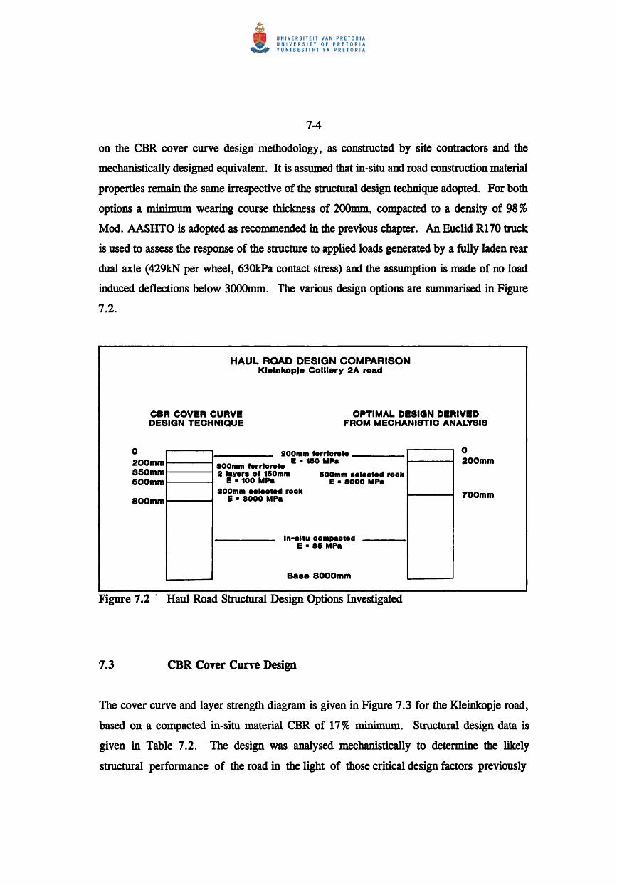
on the CBR cover curve design methodology, as constructed by site contractors and the
mechanistically designed equivalent. It is assumed that in-situ and road construction material
properties remain the same irrespective of the structural design technique adopted. For both
options a minimum wearing course thickness of 200mm, compacted to a density of 98 %
Mod. AASHTO is adopted as recommended in the previous chapter. An Euclid R170 truck
is used to assess the response of the structure to applied loads generated by a fully laden rear
dual axle (429kN per wheel, 630kPa contact stress) and the assumption is made of no load
induced deflections below 3000mm. The various design options are summarised in Figure
7.2.
HAUL ROAD DESIGN COMPARISON KlelnkopJe Colliery 2A road
CBR COVER CURVE DESIGN TECHNIQUE
OPTIMAL DESIGN DERIVED FROM MECHANISTIC ANALYSIS
o 200mm 360mm 600mm
800mm
200mm ferrlorete ___ _
800mm ferrlor .te E • 160 MPa 1-----1
2 layer. of 16 Omm 800mm .eleoted rook E· 100 UPa E· 8000 UPa
800mm •• Ieot ed rook Pa E. 8000 M
In-.ltu oompaoted E • 88 MPa
Ba.e 3000mm
o 200mm
700mm
Figure 7.2' Haul Road Structural Design Options Investigated
7.3 CDR Cover Curve Design
The cover curve and layer strength diagram is given in Figure 7.3 for the Kleinkopje road,
based on a compacted in-situ material CBR of 17 % minimum. Structural design data is
given in Table 7.2. The design was analysed mechanistically to determine the likely
structural performance of the road in the light of those critical design factors previously

Table 7.2
Layer
1
2
3
4
5
7-5
CBR Structural Design Data
Lay~r Thickness
(mm)
200
150
150
300
In-situ
Mod. AASHTO CDR Assumed compaction ('*') achieved effective Material description
('II) elastic modulus (MPat
98 90 150 Selected ferricrete O4/G5
95 50 100 Selected ferricrete O4/G5
93 35 100 Selected ferricrete O4/GS
>200 3000 Selected sandstone, < 300mm block size or < % layer thickness
17 85 In situ compacted G7
• Values derived from Tables 6.1 and 6.10
CBR DESIGN COVER CURVE KlelnkopJe Colliery block 2A road
Pavement depth (mm) o~--~. --~~~~~~~~~l~l~~~---.~~~~~i ~~-1~1~i~--~.--~~~~~~~~-~~~~~
- 260 ...... · ........ T .... · .. ·T ...... r .. ·r .. ~ .. TTT' .. · .. · ...... · .... T .. · .... T· .'1' .... ;.... ~ 1 r .. · .. · .. · .. · .... ·T ........ r .. · .. r .. T·TTTT -1500 .......... · .... r ........ r .... ·r .. r .. ~ .. TTl' .................. 1" ...... ~ .... ·T· iii ~ i ....... · .. r· .... r .... r .. r-rtT -7150 .. · ............ r ........ r-.... r--.. rTTTT .... ··· .... · .. · .... ;· ...... ~ ...... ~ ..... ~ .... : ... : ... ~ .. ~ .................... : · ...... ·r .. ·T· .. T .. TTTT
- 1 000 ................ ! .......... ! ....... ~ ..... '!' ••• ?.! .. ? .. !.. ............ ..! .......... '!' ...... ? .... ! .... ! ... ! ... ! .. ! .................... '!' .......... ! ....... ? .... ! .... ! ... '!' •• ! .. '!'.
; ~ ;~~~~~ ; ~ E~~E~E ; ~ i!~ii! - 12 50 .. ··· .. · .... ···T .. · .... ·T· .... T .... r .. ·rrr·~· .... ....... ·T· ...... ·T· .. · .. r· .. ·I· .. r .. r·1 .. r· · .. · .. · .. · ........ r ........ T····T· .. ·~ .... r .. r·TT - 1 1500 ····· .... · .. · .. i·· ...... ··~ ...... ·~· .... r· .. t .. i··t·: .............. ..~ .. · ...... ·t .... ··t .. ··~ .. ·i .. ·i .. ~ .. ~ .. · ........ · ........ t ........ t· .... ·t .... ·j·· .. ~· .. r-·i .. r·
: : ': : ::: :I:: r : I: : : I : I I : I I
-17150 ........ · ...... r ........ r .... T .... rr·: rr ................ r-........ r .. · .. r .. l·lTTT ............ · .... T ........ l .. · .. r .. T· .. rTTl - 2000 ···············i·······'··~·······i·····r··1 'i"r'i' .............. ··~ .. ·· .. · .. T······r .. ··r··i···~··i··~· ········ .. ····· .. ·r·········r·· .. ··r····l .. ··~···r··I··r· - 2260 ···············I··········~·······~·····. "r"I"r'I' .............. ··~·········T·· .. ··r .... I···I···~··I··~· ·········· .. ··· .. ·r······· .. I······I····1····i··T··~··r· - 21500 .. ·· .... · ...... T .... · .... 1·· .. ···~.. r'T"r"rr ............. ·1· .. · ...... r .... ·T .. ··r .. r .. r·T'1· ...... ··· .... · .. ·T ...... · .. r ...... r .... I···1 .. T·TT·
: : : : : : : : ::: : : : : : ::: : : : : : - 2760 ............... .:. .......... ~....... . ... Z .... E ... .:. •• C .. .:.. .............. ..~ .......... Z ....... E ..... .:. ... .:. .. ~ •• .:. .. ~. .. ................ z, ......... CO ...... .:. .... .:. ••• ~ ... Z .. .:. .. I ••
~~~~~ .:::::::::::::::I:::::::·:I::~~~~m ::;::::::::::::::~:1;fE[tli: :::::.::::·::.: .. 1:::·::::·:1::::::1::::1:::1::1::11: -4000~--~~~~~~----~~~~~~--~--~~~~
1 10 100 1000 CBR
Figure 7.3 CBR Cover Curve For Kleinkopje Colliery Comparative Analysis

7-6
identified. In the case of Kleinkopje, a performance index of 7 was used in conjunction with
300kt monthly coal production which gave an upper limit to the load induced strains of
approximately 2000 microstrain.
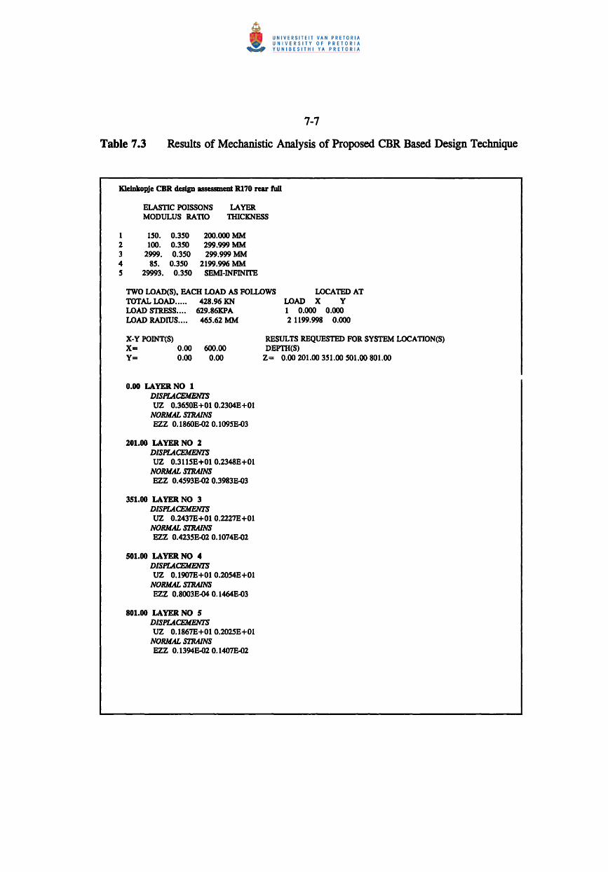
The data in Table 7.3 relates to the results of the mechanistic analysis of the CBR derived
cover curve design. It is evident that excessive vertical compressive strains are generated
in the top of layers 2 and 3. Strains in excess of 2000 microstrain are associated with an
unacceptable amount of rutting and pavement deformation for this particular level of
performance and traffic. Surface deflections generated by the applied load of 3 ,65mm, do
not appear excessive but when accompanied with the severe load induced strains, will
eventually initiate structural failure. The comments made regarding the inapplicability and
under-design apparent with the CBR design technique are borne out by these results,
specifically the large vertical strains developed in the pavement as the design layer strengths
approach the cover curve line. It is thus prudent to investigate design alternatives based on
the results discussed in Chapter 6.
7.4 Optimal Haul Road Design
The design proposed is based upon the fmdings of the mechanistic analysis of existing haul
roads. Of particular importance in this respect is the Kriel Colliery site 3 road which
incorporates the stabilised layer. Whilst stabilisation techniques are expensive and the layers
themselves subject to cracking if not adequately designed, the most tractable option is to use
mine spoil rock material in place of the stabilised layer. The design adopted is depicted in
Figure 7.2 and described in Table 7.4. The design is analysed mechanistically to determine
the likely structural performance of the road in the light of the critical design factors
previously identified.
The data in Table 7.5 relates to the results of the mechanistic analysis of the optimal design.
It is evident that no excessive vertical compressive strains are generated in the structure,
primarily due to the support generated by the shallow rock layer. Maximum vertical strains
of 1505, 70 and 1078 microstrain are developed in layers 1, 2 and 3 respectively. Maximum
7-7
Table 7.3 Results of Mechanistic Analysis of Proposed CBR Based Design Technique
KleiokopJe eRR design assessment R170 rear fuD
1 2 3 4 5
ELASTIC POISSONS LAYER MODULUS RATIO THICKNESS
ISO. 0.350 100. 0.350
2999. 0.350 85. 0.350
29993. 0.350
200.oooMM 299.999MM 299.999 MM
2199.996 MM SEMI-INFINITE
TWO LOAD(S). EACH LOAD AS FOLLOWS TOTAL LOAD..... 428.96 KN
LOCATED AT LOAD X Y
LOAD STRESS.... 629.86KPA LOAD RADIUS.... 465.62 MM
X-Y POINT(S) X= 0.00 600.00 Y= 0.00 0.00
0.00 LAYER NO 1 DISPLACEMENTS UZ 0.3650E+Ol 0.2304E+Ol
NORMAL STRAINS EZZ 0.18608-02 0.10958-03
201.00 LAYER NO 2 DISPLACEMENI'S UZ 0.3115£+010.23488+01
NORMAL STRAINS EZZ 0.45938-02 0.39838-03
351.00 LAYER NO 3 DISPLACEMENI'S UZ 0.2437E+Ol 0.2227E+Ol
NORMAL STRAINS EZZ 0.4235B-02 0.1074B-02
501.00 LAYER NO 4 DISPLACEMENI'S UZ 0.1907E+Ol 0.2054E+Ol
NORMAL STRAINS EZZ 0.8003E-04 0.I464E-03
801.00 LAYER NO 5 DISPLACEMENIS UZ 0.1867E+Ol 0.2025£+01
NORMAL STRAINS EZZ 0.13948-02 0.1407B-02
1 0.000 0.000 2 1199.998 0.000
RESULTS REQUESTED FOR SYSTEM LOCATION(S) DEPTH(S)
Z= 0.00 201.00 351.00 501.00 801.00
7-8
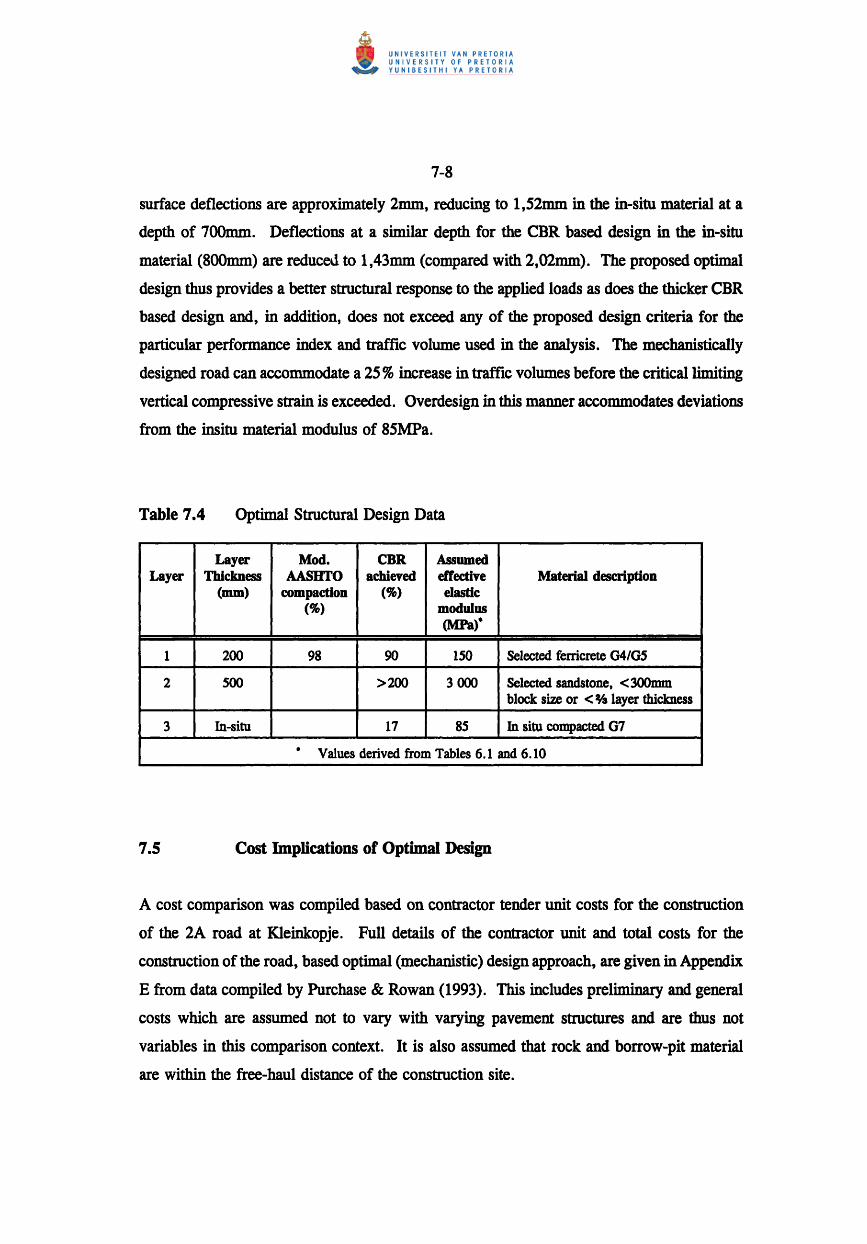
surface deflections are approximately 2mm, reducing to 1,52mm in the in-situ material at a
depth of 700mm. Deflections at a similar depth for the CBR based design in the in-situ
material (800mm) are reduceU to 1,43mm (compared with 2,02mm). The proposed optimal
design thus provides a better structural response to the applied loads as does the thicker CBR
based design and, in addition, does not exceed any of the proposed design criteria for the
particular performance index and traffic volume used in the analysis. The mechanistically
designed road can accommodate a 25 % increase in traffic volumes before the critical limiting
vertical compressive strain is exceeded. Overdesign in this manner accommodates deviations
from the insitu material modulus of 85MPa.
Table 7.4 Optimal Structural Design Data
Layer Mod. CDR Assumed Layer Thickness AASHTO achieved effective Material description
(nun) compaction (%) elastic (%) modulus
(MPa).
1 200 98 90 150 Selected fenicrete 04/05
2 500 >200 3 ()()() Selected sandstone, < 300mm block size or < % layer thickness
3 In-situ 17 85 In situ compacted 07
• Values derived from Tables 6.1 and 6.10
7.5 Cost Implications of Optimal Design
A cost comparison was compiled based on contractor tender unit costs for the construction
of the 2A road at Kleinkopje. Full details of the contractor unit and total cosu, for the
construction of the road, based optimal (mechanistic) design approach, are given in Appendix
E from data compiled by Purchase & Rowan (1993). This includes preliminary and general
costs which are assumed not to vary with varying pavement structures and are thus not
variables in this comparison context. It is also assumed that rock and borrow-pit material
are within the free-haul distance of the construction site.

7-9
Table 7.5 Results of Mechanistic Analysis of Proposed Optimal Design
KleiDkopje optimal design assessment RI70 rear full
1 2 3 4
ELASTIC POISSONS LAYER MODULUS RATIO TIlICKNESS
150. 0.350 2999. 0.350
85. 0.350 29993. 0.350
200.OOOMM 499.999MM
2299.995 MM SEMI-INFINITE
TWO LOAD(S),EACH LOAD AS FOLLOWS TOTAL LOAD..... 428.96 ICN LOAD STRESS.... 629.86KPA LOAD RADIUS.... 465.62 MM
X-Y POINT(S) X= 0.00 600.00 y= 0.00 0.00
0.00 LAYER NO 1 DlSPLA.CEMENl'S UZ 0.2072£+01 0.1555£+01
NORMAL STlWNS EZZ 0.1505£-02 0.3127£.03
201.00 LAYER NO Z DISPLA.CEMENl'S UZ 0.1579£+010.I644E+Ol
NORMAL STRAlNS EZZ 0.7030£-04 0.2137£-04
701.00 LAYER NO 3 DlSPLA.CEMENl'S UZ 0.15208+01 0.16208+01
NORMAL STlWNS EZZ 0.1078£-02 0.10778-02
LOCATBDAT LOAD X Y
1 0.000 0.000 2 1199.998 0.000
RESULTS REQUESTED FOR SYSTEM LOCATION(S) DEPTH(S)
Z= 0.00 201.00 701.00
The variable costs taken into account are those of the volume and area of materials required
and the associated costs of placing and compaction. Costs are analysed under two categories;
preliminary and general costs and haul road construction costs. Preliminary and general
costs are assumed to remain constant for the purposes of the analysis and amount to
R410ooo, or RI64 000 per kilometre of road. Road drMinage, berm construction and
finishing are also assumed to remain constant irrespective of the design chosen.
Table 7.6 summarises the amounts and cost of the various activities as they apply to the CBR
and optimal mechanistic-based designs. From an analysis of the construction costs for each
design it is seen that a cost saving of R155 060, or 25 % could be realised by adopting the

7-10
Table 7.6 Cost Comparison of Design Options (Excluding Preliminary and General
Costs).
CBR-BASED DESIGN OPl1MAL DESIGN
ACTIVITY AMOUNT COST (R) ACTIVITY AMOUNT COST (R)
Compaction of 27000m2 9720 in-situ 230m3 1256
Compaction and 405Om3 8465 Compaction of 10530m3 22008 treatment of 6480m3 16913 in-situ
road-bed
Place and 7300m3 39858 compact rock fill
layer
Place and 18750m3 102375 Place and 876Om3 47830 compact rock compact rock
layer fill layer
Place and 9375m3 108468 compact sub-
base layer
Place and 9375m3 108468 compact base
layer
Place and 3125Om3 170625 compact rock
base layer
Place and 12500m3 144625 Place and 12500m3 144 625 compact wearing compact wearing
course course
Finish, including l000m3 8670 Finish, including l000m3 8670 drains and berms
75OOm3 drains and
7500m3 56 175 berms 56175
2,5km 7650 2,5km 7650
TOTAL 612643 457583
mechanistic-based optimal design, by virtue of the reduced material volumetric and
compaction requirements. In terms of total construction cost (including preliminary and
general costs), a 15% cost saving per kilometre is realised. In addition, further benefits
should accrue in terms of reduced operating and maintenance costs arising from the superior
structural performance of the road as evidenced from the foregoing analysis.
7-11
7.6 Summary
The design criteria derived from the mechanistic analysis of existing haul roads was used in
this section to complete a comparative structural design costing exercise for a road recently
constructed at Kleinkopje Colliery. Two design options were considered; the AMCOAL
CBR cover curve design methodology and the mechanistically designed optimal equivalent,
based on the design catalogue presented in Chapter 6 and the particular in-situ material
strength and load characteristics prevalent in the 2A area at Kleinkopje.
It was assumed that in-situ and road construction material properties remain the same
irrespective of the structural design technique adopted. For both options a minimum wearing
course thickness of 200mm was used, compacted to 98% Mod AASHTO. The in-situ
material was ascribed a CBR of 17 and a modulus of 85MPa. The CBR cover curve desigu
incorporated 4 layers, including a rock-fill layer above the in-situ material. In contrast, the
optimal mechanistic equivalent for this road consisted of 2 layers above insitu.
From an analysis of vertical compressive strains developed in each layer due to the applied
load of a R170 truck, it was found that excessive strains were developed in layers 2 and 3
of the CBR-based design. The optimal design did 110t evidence any excessive strains,
primarily due to the support generated from the shallow rock layer. The proposed optimal
design thus provided a better structural response to the applied loads than did the thicker
CBR based design and, in addition, did not exceed any of the proposed design criteria for
the particular performance index and traffic volume used in the analysis.
A cost comparison of the two designs was compiled based on contractor tender unit costs for
the construction of the 2A road at Kleinkopje. The variable costs taken into account were
those of the volume and area of materials required and the associated costs of placing and
compaction. By virtue of the reduced material volumetric and compaction requirements
associated with the optimal design, a cost saving of R155 060, or 25 % was realised. In
terms of total construction cost (including preliminary and general costs), a 15% cost saving
was realised over the CBR-based design.

7-12
The optimal mechanistic design derived in the analysis is based on the particular in-situ
material strength, applied load and required road performance (at a particular traffic volume)
characteristics. From Equation [6.1] it may be seen that if traffic volume from the 2A pit
were to increase, the structural performance of road, based on the CBR design, would further
deteriorate. However, even with a 25% increase in traffic volume, the strains generated in
the various layers of the mechanistically designed pavement remain below the design criteria.
When departures are made from the 85MPa in-situ material, Table 6.10 can be used to
down-grade the applicable material modulUS according to the particular CBR value of the
material. If the type of truck changes, or the required performance index or tonnage hauled
on the road, these can be modified in the analysis itself, following Equation [6.1]. In this
respect the mechanistic design methodology and catalogue of values is transferable between
sites.

8-1
CHAPTERS
SUMMARY OF STRUCTURAL DESIGN RESEARCH
8.1 DCP Analysis of Pavements
Regarding the empirical analysis and quantification of existing pavement structural designs,
the use of the Dynamic Cone Penetrometer in the context of haul road structural design
investigations was employed to determine the location of various pavement layers, the
California Bearing Ratio (CBR) values of these various layers and the overall balance of the
structural design. The results generated in the fJIst instance conftrm the classification of test
sites proposed in the experimental design for the site location matrix. In general, those sites
showing a shallow structure, in which the majority of the pavement strength lies in the upper
layers may be more sensitive to increased wheel loads and consequential failure of the upper
layers. A deep structure, in contrast, would be less sensitive to any increase in wheel loads,
but may well show signs of excessive permanent deformation in the weaker upper layers.
The extent to which these effects are seen in haul roads can only be reliably determined from
in-situ deflection measurements.
It has been shown that the balance profile approach has limited application in the design of
mine haul roads since one of the most efficient and structurally sound designs incorporates
a rock layer at a shallow depth resulting in a poorly balanced shallow strength profile. In
addition, the pavement strength-balance concept focuses on the upper 1,8m of material,
which, for most mine sites generally includes a portion of sub-grade. The strength-balance
concept does not address whether the pavement as a whole is suited to the sub-grade strength.
In general terms the strength balances to be avoided are those of inverted structures and, to
a lesser extent, poorly balanced deep. Both are associated with excessive elastic vertical
compressive strains in the pavement.
8.2 California Dearing Ratio (CDR) Design Procedure
Although the DCP data affords an insight into the actual road structure as opposed to the

8-2
design structure and the strength of each layer actually achieved in the field, the extent to
which each type of design fulfils the structural performance requirements can only be
determined from analysis of the response of each layer to the applied loads. As a precursor
to the analysis, the California Bearing Ratio design technique was investigated in which CBR
data generated from the DCP investigation is compared to actual cover requirements
predicted from the CBR design method. Although the CBR method is a simple and straight
forward design met.hod based on and improved by considerable practical experience,
numerous disadvantages were found when applying the method to mine haul road design
problems. Mine haul road structures consist of various layers of differing material each with
its own specific elastic and other properties. More specifically, the CBR method was based
on empirical results relating to the design of asphalt-surfaced airfield pavements for wheel
gear loads up to 4 400kN. When aggregate-surfaced mine haul roads are considered in
conjunction with stabilised bases, albeit at similar load levels, the same approach is of
questionable validity. The graphical relationship proposed by Ahlvin in conjunction with the
modified CBR design technique would therefore also not appear to be applicable to haul road
structural design. Simple extrapolation of these empirical design criteria to accommodate
higher axle loads and different pavement layer materials can lead to serious errors of under
or over-design.
The deficiencies inherent in the development of the CBR design method militate against using
the techniques for the structural design of mine haul roads. When the results of the DCP
redefmed layer strengths are analysed in conjunction with the CBR cover curves generated,
it would appear that the method, when applied judiciously, can be used to determine safe
(total) cover over in-situ materials, although the extent of over or under design associated
with the method cannot be qualified. The method is thus exclusively recommended to design
cases where no surface layers exist above standard gravel bases. Where cemented or
stabilised layers are included in the design, or where the optimal structural design is sought,
due to the very different properties of the layer in comparison to normal roadbuilding
gravels, a mechanistic design techniques should be employed which can account for the
different material properties and more accurately predict their performance.

8-3
8.3 Derivation of Mechanistic Structural Design
The derivation of the design criteria for the mechanistic design of surface mine haul roads
was based on the structural performance categorisation of mine haul roads. Stresses and
strains generated from the multi-layer elastic solution for the particular road test section were
then compared with the structural performance and traffic volume categorisation to
established suitable design criteria. Construction material elastic moduli were assessed in
terms of both the TRH14 and TRH20 classification and the DCP derived empirical
relationship whereby suitable moduli for the various classes of granular materials used in haul
road construction were derived.
Two design criteria were proposed with which to assess the structural performance of mine
haul roads, namely factor of safety (FOS) for the two uppermost layers and vertical
compressive strain for each layer below the top layer. It was found that the vertical strain
criterion correlates well with structural performance/traffic volume of the road; those mine
sites exhibiting poor performance and an associated excessive deformation/maximum
deflection were seen to be associated with large vertical compressive strain values in one or
more layers. From analysis of the data it was found that when using a performance index
of 7 and 300kt coal production per month, an upper limit of 2000 microstrain should be
placed on layer strain values. Strain values exceeding this value have been shown to be
associated with unacceptable structural performance in both public road and airfield design.
The depth of influence at which load induced stresses are no longer felt was identified at
approximately 3000mm pavement depth.
With regard to the FOS design criteria for the upper layers, it is concluded that this criteria
is not applicable to haul road design since the applied stresses were much lower than the
ultimate strength of pavement layer material, which was normally not mobilised. In addition,
the location of the point in the wearing course layer at which the FOS is calculated is very
much dependant on layer thickness, stress reversals being seen in relatively thin, poorly
supported layers. In the absence of any defmitive criterion, a 200mm layer of compacted
(95-98 % Mod. AASHTO) good quality gravel is recommended. This recommendation is
derived from the observation of mine site wearing course layers which exhibited adequate

8-4
structural performance.
The optimal mechanistic structural design of a surface mine haul road embodies the selection
of target effective elastic modulus values for the construction materials available and the
placement of those materials such as to optimise their performance both as individual layers
and over the entire structure. Performance has been analysed in terms of minimum. wearing
course thickness and compaction and the limiting design criteria of vertical strain in the base,
sub-base and sub-grade layers. In addition, of the various design options analysed at each
mine test site, the inclusion of a rock layer immediately below the wearing course proffered
the structure increased resilience to the applied loads without recourse to excessive structural
thickness.
8.4 Selection of Effective Elastic Modulus Values
Materials available on site for the construction of roads is derived from borrow pits or the
pit itself. Borrow pit material comprises generally ferricrete and may be classified (following
TRH14) as G4-G6. Selection criteria for these materials were analysed in terms of material
grading, Atterberg limits, CBR, swelling and field compaction characteristics in order to
assign target effective elastic modulus values to these materials. It was found that the modal
material classification (ignoring in-situ material) is that of a GS-G6 gravel or low quality
gravel where local mine ferricrete is used. To reduce the requirements for testing materials
and to enhance the practical application of the mechanistic design method, it is prudent to
adopt blanket modulus values where these, or other essentially similar material types are
encountered. A modulus range of 150-200MPa is proposed for G4-G6 gravels when used
as a wearing course and 75-100MPa for the same material when used as a base or sub-base
layer. These values are slightly lower than typical published values, thereby accommodating
local deviations from the standard material classification. Values for the modulus of the in
situ sub-grade material are very much site and material specific and range from 17MPa to
388MPa and often exhibit stress softening. Dump rock material, consisting of selected
sandstone or parting should be assigned a target effective elastic modulus value of 3000 MPa.

8-5
Whilst the empirical relationship proposed for detennining the seed value for the effective
elastic modulus for the mechanistic model could be advanced as a means of determining
modulus values for insitu material, although some trend is evident, the confidence limits
calculated for the relationship are large and a solution within 80 % confidence extends over
two decades. The associated standard error of estimate is 0,487 and R2=68%. It is
concluded that it is difficult to motivate for the existence of a direct relationship between
effective elastic modulus and DCP penetration rate due to the very different testing
techniques employed to derive different characteristic parameters for the same material.
Where a modulus value is required for pavement layer modelling, the use of DCP probe
derived CBR values in conjunction with published data provide the most tractable approach
to ascertaining suitable modulus values for this material.
8.5 Recommended Mechanistic Design Procedure
Recommendations regarding the structural design of surface mine haul roads are centred on
the inclusion of a dumprock layer within the structure. The optimal location of this layer
was found to be immediately below the wearing course layer, thereby reducing deflections
(and consequent deformation) in the lower layers to a minimum. Using this approach, a
reduced structural thickness was realised without the attendant deformation and reduction in
structural performance that would otherwise be evident without a rock layer.
The design criteria derived from the mechanistic analysis of existing haul roads was used to
complete a comparative structural design for a road recently constructed at Kleinkopje
Colliery. For comparative purposes, two design options were considered; the AMCOAL
design based on the CBR cover curve design methodology, as constructed by site contractors
and the mechanistically designed optimal equivalent. Finally, the cost implications of the
optimal design were analysed.
The optimal design incorporated a 200mm ferricrete wearing course layer with an effective
elastic modulus of 150MPa and a 500mm layer of selected rock with an effective elastic
modulus of 3000MPa constructed upon in-situ material with an effective elastic modulus of

8-6
85MPa. The structure was subjected to a 429kN dual rear wheel load and a 630kPa contact
stress. It was seen that no excessive vertical compressive strains were generated in the
structure, primarily due to the support generated by the shallow rock layer. Maximum
surface deflections were approximately 2mm, reducing to 1,52mm in the in-situ material at
a depth of 700mm. Deflections at a similar depth for the CBR based design in the in-situ
material (800mm) were reduced to 1 ,43mm (compared with 2,02mm). The proposed optimal
design thus prov!des an improved structural response to the applied loads than does the
thicker CBR based design and, in addition, does not contravene any of the proposed design
criteria for the particular performance index and traffic volume used in the analysis ..
A cost comparison of the two designs was compiled based on contractor tender unit costs for
the construction of the 2A road at Kleinkopje. The variable costs taken into account were
those of the volume and area of materials required and the associated costs of placing and
compaction. By virtue of the reduced material volumetric and compaction requirements
associated with the optimal design, a cost saving of R155 060, or 25% was realised. In
terms of total construction cost (including preliminary and general costs), a 15 % cost saving
per kilometre was realised over, ~e CBR-based design.
The optimal mechanistic design derived in the analysis was based on the particular in-situ
material strength, applied load and required road performance (at a particular traffic volume)
characteristics. If the type of truck changes, or the required performance index or tonnage
hauled on the road, these can be modified in the analysis itself according to the proposed
relationship between maximum strain and traffic volume/performance. In this respect the
mechanistic design methodology and catalogue of values is transferable between sites which
exhibit construction materials or traffic volumes within the inference space of the data
analysed.