609 DRILLED SHAFT FOUNDATIONS · Drilled Shafts: Construction Procedures and Design Methods is a...
25
STRUCTURES January 2005 609 DRILLED SHAFT FOUNDATIONS 609-1 Description A drilled shaft is a deep circular hole in the ground filled with reinforced concrete. The drilled shaft transfers the weight and loads on a structure to soils and bedrock deep underground. Drilled shaft depths can range from 6 feet (2 meters) for pole foundations to 130 feet (40 meters) for bridge foundations. A drilled shaft transfers loads to rock and soil by one of the following methods: 1. The shaft transmits loads to the ground by the friction developed between the outside vertical surface of the shaft and the adjacent rock or soil. This is called a skin-friction drilled shaft. 2. The shaft transmits loads to a layer of bedrock or hard soil that the drilled shaft sits on. The loads are transferred through the bottom of the shaft to the ground, hence the term end-bearing drilled shaft. Skin friction is not relied upon to transmit loads, although it may be present in an end-bearing drilled shaft. End-bearing drilled shafts are occasionally widened at the base to spread out the load. Underreaming to form a bell-shaped shaft tip does this. 3. When a drilled shaft is designed to transmit loads by a combination of end-bearing and skin friction, the shaft is designated as a combination end-bearing, skin-friction drilled shaft. The most common type of drilled shafts is the skin-friction type. End-bearing shafts are not as common because of the additional cost of underreaming (forming the bell shape) and the need to send an Inspector down in the hole to inspect the bottom of the shaft. Combination end-bearing, skin-friction shafts without bells are becoming more common as Foundation Designers get better at predicting end-bearing capacities for soil and rock. Construction Procedures Are Critical Unlike driven piles, drilled shafts are more reliant on a multitude of construction procedures any of which could severely reduce the capacity of the shaft if not followed properly. As a result, the inspection of drilled shafts is much more demanding on the Inspector than pile driving. Inspectors must have a wider range of skills including soil identification, rebar inspection, concrete testing, and equipment familiarity. To quote from Drilled Shafts: Construction Procedures and Design Methods (see references), “The most frequent cause of drilled shaft failures are almost always attributed to improper construction procedures.” With this in mind, inspection must play a very active role in drilled shaft construction. Any Inspector assigned to a drilled shaft operation must have plenty of prior experience in this type of work. Inspectors who are inexperienced at doing a drilled shaft inspection should not be leading such a critical operation. 609-1.03 Installation Plan The Contractor must submit a detailed installation plan describing the equipment and tools to be used and the methods for constructing the drilled shaft. The amount of detail required should depend upon the anticipated site conditions and the complexity of the drilled shaft operation. An installation plan fulfilling all twelve points listed in the Standard Specifications should include sketches and equipment information. If drilling slurry is to be used, the plan submitted may be quite large. The intent of submitting a drilled shaft installation plan is to get the Contractor and the Resident Engineer to plan Construction Manual 609 - 1
Transcript of 609 DRILLED SHAFT FOUNDATIONS · Drilled Shafts: Construction Procedures and Design Methods is a...
STRUCTURES January 2005
609 DRILLED SHAFT FOUNDATIONS
609-1 Description
A drilled shaft is a deep circular hole in the ground filled with reinforced concrete. The drilled shaft transfers the weight and loads on a structure to soils and bedrock deep underground. Drilled shaft depths can range from 6 feet (2 meters) for pole foundations to 130 feet (40 meters) for bridge foundations.
A drilled shaft transfers loads to rock and soil by one of the following methods:
1. The shaft transmits loads to the ground by the friction developed between the outside vertical surfaceof the shaft and the adjacent rock or soil. This is called a skin-friction drilled shaft.
2. The shaft transmits loads to a layer of bedrock or hard soil that the drilled shaft sits on. The loads aretransferred through the bottom of the shaft to the ground, hence the term end-bearing drilled shaft.Skin friction is not relied upon to transmit loads, although it may be present in an end-bearing drilledshaft. End-bearing drilled shafts are occasionally widened at the base to spread out the load.Underreaming to form a bell-shaped shaft tip does this.
3. When a drilled shaft is designed to transmit loads by a combination of end-bearing and skin friction, theshaft is designated as a combination end-bearing, skin-friction drilled shaft.
The most common type of drilled shafts is the skin-friction type. End-bearing shafts are not as common because of the additional cost of underreaming (forming the bell shape) and the need to send an Inspector down in the hole to inspect the bottom of the shaft. Combination end-bearing, skin-friction shafts without bells are becoming more common as Foundation Designers get better at predicting end-bearing capacities for soil and rock.
Construction Procedures Are Critical
Unlike driven piles, drilled shafts are more reliant on a multitude of construction procedures any of which could severely reduce the capacity of the shaft if not followed properly. As a result, the inspection of drilled shafts is much more demanding on the Inspector than pile driving. Inspectors must have a wider range of skills including soil identification, rebar inspection, concrete testing, and equipment familiarity.
To quote from Drilled Shafts: Construction Procedures and Design Methods (see references), “The most frequent cause of drilled shaft failures are almost always attributed to improper construction procedures.” With this in mind, inspection must play a very active role in drilled shaft construction. Any Inspector assigned to a drilled shaft operation must have plenty of prior experience in this type of work. Inspectors who are inexperienced at doing a drilled shaft inspection should not be leading such a critical operation.
609-1.03 Installation Plan
The Contractor must submit a detailed installation plan describing the equipment and tools to be used and the methods for constructing the drilled shaft. The amount of detail required should depend upon the anticipated site conditions and the complexity of the drilled shaft operation. An installation plan fulfilling all twelve points listed in the Standard Specifications should include sketches and equipment information. If drilling slurry is to be used, the plan submitted may be quite large.
The intent of submitting a drilled shaft installation plan is to get the Contractor and the Resident Engineer to plan
Construction Manual 609 - 1
STRUCTURES January 2005
ahead of time on what materials, equipment, and methods will be used to construct the drilled shafts. The Department wants a well thought-out plan that demonstrates the Contractor is ready and capable of doing the work. Unlike mistakes in an above ground structure, mistakes buried 33 to 100 feet (10 to 30 meters) underground are not easy to detect and repair.
The Contractor must be permitted to freely adjust the installation methods as ground conditions warrant. However this need to rapidly adjust the drilling operation does not negate the need for an initial installation plan. The point of the installation plan is to ensure the drilling Contractor has adequately prepared for the work. This preparation helps minimize the Department’s risk of having to deal with defective shafts because of haphazard and uncoordinated work methods. The plan gives the Resident Engineer an opportunity to verify that the Contractor's work is in conformance with the Project Plans and Specifications and helps avoid those unpleasant surprises during drilling that could lead to a Department-ordered work stoppage or rejection. Of course, the more details the plan gives, the more likely that issues can be resolved ahead of time. Sketchy incomplete Project Plans, submitted just to meet a contract requirement, usually serve as a warning for many problems in the field.
Plan Evaluation
The Resident Engineer is responsible for reviewing and approving the installation plan. The Geotechnical Section of Materials Group or the Consultant Geotechnical Engineer for the project will help review the plan and establish guidelines. They even have sample Project Plans from previous jobs that can help the Contractor achieve a complete submittal the first time. However it is the Resident Engineer who must be satisfied that the plan is complete enough and in sufficient detail to allow the Contractor to proceed with the work.
If the Resident Engineer has not been involved with a drilled shaft installation before, it will be difficult to evaluate the suitability of the Contractor’s equipment and installation procedures. Geotechnical Section can help with this. Keep in mind that the objective of the installation plan is not so much a verification tool for the Department as it should be a planning tool for the Contractor. The Resident Engineer’s job is to ensure that the Contractor has adequately planned the work. If the Resident Engineer can’t understand the plan because of vagueness, generalities, and lack of detail, chances are the drilling Contractor has no clear idea what is to be done.
Minor details omitted from the plan can be discussed in a preconstruction meeting. Major details such as the type of equipment used, rebar support and spacers, casing procedures for the hole, and drilling slurry procedures must be shown on the plan.
Preconstruction Meeting
Although it is not usually required by the contract, it is highly recommended that the Resident Engineer hold a preconstruction meeting prior to drilling for all but the simplest drilled shafts.
Points to cover at the meeting include:
• the details of the Contractor’s installation plan, including any clarification required by the Resident Engineer;
• contract pay limits and method of measurement; • inspection requirements, and assistance by the Contractor during inspections; • contingencies for caving, groundwater, utilities, boulders, and other obstructions; and • safety precautions.
Construction Manual 609 - 2
STRUCTURES January 2005
The goal of the meeting should be that the Resident Engineer and the Inspector walk away with a clear understanding of the Contractor’s installation plan and how the Contractor intends to construct the drilled shafts. At the same time, the Contractor should have an understanding of how the Department intends to inspect the shafts and how both need to work together so the Inspector can effectively do his or her work. References
Space limitations in this manual prevent the reader from obtaining everything he or she needs to know to properly oversee and inspect drilled shaft construction. However there are three excellent references cited at the end of this chapter that can easily fill in the gaps.
The Drilled Shaft Inspector’s Guide is a handy little booklet that every Inspector should have when inspecting drilled shafts. It concisely describes the drilled shaft construction processes and the Inspector’s basic duties during construction.
Drilled Shafts: Construction Procedures and Design Methods is a comprehensive look at drilled shaft construction. It is definitely the industry bible and the most informative in explaining all the little but important details of drilled shaft construction. Each district office as well as field offices that do a lot of drilled shaft work should have a copy.
Chapter 6 and 9 of the California Foundation Manual are two other excellent sources of information on drilled shaft methods and inspection duties. Unlike the drilled shaft bible, which was written by two college professors, these chapters were written by practicing engineers and construction technicians. The information is concise and the explanations more descriptive. Copies are available from the ADOT library.
As with all references, ADOT’s specifications override any construction specifications mentioned in these publications.
609-2 Materials
609-2.01 Concrete
Drilled shafts are one of the few reinforced concrete structures where the Department will let the Contractor get away with pouring “soupy” looking concrete. Fluidity of the concrete is very important for successful drilled shaft construction. Subsection 609-3.05 will have more to say about concrete properties for drilled shafts but for now it is important to remember that the mix design needs to be reviewed for compliance with Subsection 609-2.01 as well as for the following:
• the slump should be within the 5 to 6 inches (125 and 150 millimeters) for the dry, uncased holes and 8 ± 1 inch (200 ± 25 millimeters) for cased holes or when the concrete is placed in water or drilling slurry;
• the maximum aggregate size should meet the limits set in the Special Provisions or in Subsection 1006-3.01; and
• any other requirements specified in Section 1006 (see Subsection 1006 of this manual). Aggregate size and grading, fluidity, and setting time are the most important characteristics of concrete for drilled shafts. These characteristics as well as strength, mixing uniformity, and segregation potential can be tricky to control in a concrete mix for drilled shafts. If the Contractor’s concrete supplier has no well established history on using the proposed mix design, the Resident Engineer must insist on trial batches. Defective concrete in a drilled shaft is incredibly harder to diagnose and repair than concrete in an aboveground structure.
Construction Manual 609 - 3

STRUCTURES January 2005
609-2.02 Reinforcing Steel
The inspection duties associated with drilled shaft reinforcing steel is no different than for reinforcing steel in other reinforced concrete structures. See Subsection 605-2 of this manual for more information.
Some drilling Contractors like to tack weld temporary rebar supports and cage stiffeners to the spirals or longitudinal steel. No welding should be done on rebar required by the Project Plans unless A706 steel is used (see Subsection 605-3.02). Any temporary supports and stiffeners should be removed before the cage is lowered completely in the hole.
609-3 Construction Requirements
Understand the Intent of the Drilled Shaft Design
Drilled shafts can be designed to transfer loads through skin friction on the outside walls, end-bearing of the shaft tip, or a combination of the two. The Resident Engineer needs to contact the Foundation Designer and to determine how the drilled shafts are designed and pass this information on to the Inspector(s).
Just as important, the Resident Engineer needs to find out which soil strata are intended to carry the loads from the shaft. Sometimes the soils near the surface are not relied upon to carry any loads and this is important to know if the Contractor wants to use permanent casing. Other times, the bearing strata can become damaged during drilling so it’s imperative to know which soils are critical to the success of the drilled shaft.
Review Subsurface Information and the Contract Documents
Before any drilling is done, the Resident Engineer and the Inspector together, should review the subsurface information gathered from the geotechnical investigation of the project. It is not necessary to read all the reports from cover to cover. Instead the goals in reviewing these documents should be:
• to become familiar with the soils expected to be encountered including the soil type, the expected depth, and the classification system used to identify the soils;
• determine if there are any soil characteristics that could give the driller problems such as groundwater, an artesian condition, loose or caving soils, heaving soils, soils containing cobbles and boulders, or manmade features, such as landfill or an old foundation; and
• know any assumptions made by the Foundation Designer and the Geotechnical Engineer on how the Contractor is supposed to construct the drilled shafts.
Of course, the Special Provisions, Project Plans, and Standard Specifications should be read. Review of the references cited in Subsection 609-1 of this manual should be required for those not involved in drilled shaft construction for one year or more. The novice Inspector should refer to Section 2 of the Workbook for Major Concrete Structures Inspection. 609-3.02 Confirmation Shafts
For projects with unusual soil or groundwater conditions, a conformation shaft may be designated in the Project Plans or Special Provisions. The intent of this confirmation shaft is to validate the construction methods described in the installation plan. It is important for the Contractor to follow his or her own installation plan until changes become necessary.
Construction Manual 609 - 4
STRUCTURES January 2005
The Inspector should carefully document the work including production times, down times, tools used, and the development of a concrete yield curve for the shaft. Any deviations from the installation plan should be noted.
Revisions to the installation should be required when site conditions are different than those assumed by the plan. The plan should be revised if the Contractor’s actual methods are significantly different from those described in the plan. The next shaft would then become the conformation shaft for the revised plan.
609-3.03 Excavation
Before the Contractor drills any holes, any embankment that the drilled shafts pass through must be constructed. The Department does not allow any construction joints in drilled shafts near the surface. Drilled shafts are often designed for bending and most of the bending occurs within 10 to 20 feet (3 to 6 meters) below the ground surface—the last place the Department wants a construction joint.
Safety First
Before drilling begins, the work area must be blue staked. In addition to searching for underground utility conflicts, the Contractor and the Resident Engineer need to look for any overhead conflicts. Plenty of head room is needed when constructing deep-drilled shafts. It is not so much the drill rig that needs the room but the crane for lifting the rebar cage and tremie. Some rebar cages can be up to 100 feet (30 meters) in length. Sometimes it is possible to get the power lines de-energized temporarily while the drilled shafts are being installed. The power company will place markers on the power line to help in judging clearance distances.
When drilling next to an underground utility, it is advisable for the Contractor to pothole first and exactly locate the utility. During drilling, caving may expose the utility. If this occurs, the Inspector should verify that the utility is well supported, if needed, and that the Contractor does not entomb it in concrete when the shaft is poured.
With sandy and SGC (sand-gravel-cobble) type soils, there is the danger of the soil collapsing near the surface as the driller advances the hole. The Resident Engineer should examine the stability of the surface soils. If the Resident Engineer believes the surface soil is too unstable to work on, he or she has the authority under 105.02 to suspend the work until the Contractor makes the area around the hole safe. Usually a safety casing can be placed around the hole in order to protect workers. Keep in mind, Subpart P of OSHA does apply to any drilled shaft excavation.
The most obvious hazard with drilled shafts is the open hole. Fall protection needs to be provided as required by Subparagraphs 1926.501(b)(7)(ii) and 1926.651(l)(2) of OSHA. Common practice is to keep unattended holes covered with plywood, steel plates, or some other protective covering. Chain link fence is to be placed around any unattended holes in accordance with Subsection 107.08. Embankments
Other reasons for having embankments built first are identical to the ones that apply to driven piles (see Subsection 603-3.04 of this manual). There is the down-drag effect caused by material placed immediately around the shaft and there is the surcharge effect caused by material placed above and beside the shaft. On bridge structures the embankment must be built to the top of berm elevation before any shafts are placed. (See Standard Drawing B-19.40)
No boulders or debris should be placed in embankments that contain drilled shafts (see Subsection 203-10.03[A]).
Construction Manual 609 - 5
STRUCTURES January 2005
Drilling the Hole
Excavated materials removed from drilled shafts, when suitable, are intended to be used in fills and embankments within the project.
The references at the end of this chapter provide more information on the drilling equipment, tools, and methods used by drilling Contractors to excavate deep holes. The type of drilling method chosen by the Contractor greatly affects the cost of the shaft and the inspection requirements placed on the Department. There are only three basic drilling methods applicable to drilled shafts. The following is a brief description of each method (see the references for more details). These methods will be referred to extensively throughout the rest of this section.
The Dry Method
The dry method is by far the quickest, cheapest, and easiest method of drilled shaft construction. The hole is drilled and remains dry and stable until a rebar cage can be placed and the concrete poured. Contractors will always try to use the dry method even if there is a risk of the shaft walls collapsing.
The Casing Method
Unfortunately not all soils remain stable during drilling—some soils heave, others squeeze, and others just collapse. To overcome this undesirable soil behavior, drillers will place a temporary casing in the hole. The casing is driven into the hole and the auger either drills inside the casing or usually just ahead of it. As the hole advances, the casing is driven further into the hole until either a layer of stable soil or the tip elevation of the shaft is reached. Sometimes drilling slurry is used to keep the hole open beneath the casing until a layer of stable soil is reached. When the shaft concrete is being placed, the Contractor will pull the casing while the concrete is still fresh. The fresh concrete should fill in any voids left by the casings and unstable soils. In some instances, the Department may allow the casing to remain permanently in place above some predetermined elevation.
The Slurry or Wet Method
This is the drilling method of last resort. Sometimes it’s the only method that will work and provide a suitably constructed drilled shaft. The cost is usually double that of the dry method so expect a request for additional compensation from the Contractor if he or she has to resort unexpectedly to this method.
The slurry method relies on thick and heavy mineral slurry to keep the surrounding soils from collapsing into the hole. The entire process is slow and subject to intensive inspection. The slurry has to be cleaned and re-circulated into the hole. The slurry head elevation must be carefully maintained even as the auger is removed from the hole to prevent any sudden pressure changes in the hole. The slurry is considered a water pollutant and has to be carefully monitored and disposed of. More on drilling slurry can be found in Subsection 609-3.02 of this manual.
A variation on the slurry method is the wet method of drilling. With this method, the drilling takes place underwater. The water behaves like slurry and stabilizes the hole. Groundwater is usually the source of water for the hole. Although Contractors have added their own water to stabilize dry holes. Subsection 609-3.02 does not apply when water is used as drilling slurry. Some of the basic principles, like letting the sand settle out before concrete placement and not dumping the silty water into an active water course, do apply. The wet
Construction Manual 609 - 6
STRUCTURES January 2005
method is often preferred over the casing method and definitely over the slurry method if it can stabilize the hole.
AASHTO designates the wet method to include both drilling slurry and water. However the drilling industry typically makes a distinction between the slurry and wet methods since the operations are significantly different.
When either the wet or slurry methods are used, the Contractor is required to provide a temporary surface casing to stabilize the ground around the hole and to prevent material from falling into the hole. This is a contract requirement specified in the AASHTO Standard Specifications for Highway Bridges (Div. 2, Subsection 5.4.5), which applies to drilled shaft construction for bridges.
Identifying Soils
One of the more important jobs of the Inspector is to verify that the soil profile shown in project boring logs is the same as encountered during drilling. The second page of the Drilled Shaft Inspection Form (see blank forms) is used by the Inspector for recording soils information. The soil type and depth should be recorded on the form as well as any other observations that would help identify the soil. Any groundwater or caving conditions should be reported.
If there are significant deviations in soil types, soil stratum depths, or other ground conditions encountered by the driller when compared to the project boring logs, the Resident Engineer and the Geotechnical Engineer for the project should be notified immediately. Design changes to the drilled shafts may be needed including lengthening the shafts to account for any unexpected soil or rock conditions. Soils identification should be done for each drilled shaft. However the Resident Engineer should decide how many drilled shafts in a drilled-shaft group need complete soil profile identification.
When rock sockets are involved, the Resident Engineer should contact the Geotechnical Engineer for the project and have him or her identify the rock formation encountered during drilling. Rock identification, including when sound bedrock is reached, can be tricky and should be left to a specialist. In most cases, the Geotechnical Engineer only needs to make one or two visits to the site to train the Resident Engineer and Inspector what to look for. Afterward if anything different is encountered, then the Geotechnical Engineer must be notified again. All rock socket depths and elevations must be measured and recorded by the Inspector. See Subsection 609-4&5 of this manual for further information.
Caving Soils
Loose sands, silts, or squeezable clays surrounding the drilled shaft can cause caving in drilled shaft excavation. Infiltrating groundwater can cause the walls of a drilled shaft to collapse.
The Contractor has several alternatives when dealing with caving soils:
• Enlarge the hole to reduce the wall curvature and decrease slope angle of the caving soil (too large a hole may cause utility conflict or interfere with an adjacent drilled shaft).
• An approved one sack grout (low cement/sand mix) can be used to fill the drilled shaft in the area of the collapsing soil, after the grout has set, the Contractor drills through the grout and continues with the hole (this method requires the prior approval of the Foundation Designer except for light pole and sign foundations).
• Use the wet method of drilling. • Use the casing method (any permanent casing must be approved by the Department).
Construction Manual 609 - 7
STRUCTURES January 2005
• Use the slurry method of drilling (Subsection 609-3.02). Inspectors must do a good job of documenting any caving conditions encountered during drilling. The depth, type of soil, and groundwater conditions must be identified. In some cases, it may be advisable to sample the soils brought up by the auger and send them to the lab for positive identification. When a drilling Contractor encounters caving soils unexpectedly and has to resort to some of the more expensive drilling methods (like the casing or slurry method) expect a request for additional costs. Good site condition identification and thorough documentation are essential in equitably resolving any caving-soil issues.
Boulders and Other Obstructions
Boulders are difficult but not impossible to remove from a drilled shaft. There are several tools available (such as grab buckets, boulder rooters, down-the-hole hammers, and hammergrabs) which can pickup, break, or remove boulders. Boulder rooters work best on the rounded, 12 to 18 inches (300 to 500 millimeter) diameter boulders usually encountered in holes in Arizona. Core barrels can be used when the boulders are prevented from shifting during drilling. More on boulder removal can be found in Drilled Shafts: Construction Procedures and Design Methods cited at the end of this chapter. Boulder removal using the previously described tools is time consuming and expensive especially when there are many boulders. Usually the Contractor will widen the hole so the boulders can ride up through the auger flights. This may be acceptable as long as the widened shaft does not interfere with adjacent shafts or with underground utilities.
Most differing site condition claims for drilled shafts in Arizona involve boulders. ADOT’s Geotechnical Section usually size drilled shafts to two times the expected boulder size. This means that the largest boulders cannot be easily removed through the auger flights. For these large rocks the Contractor has the option of widening the hole at their expense or using one of the specialized tools such as a grab bucket.
Intervention by the Resident Engineer
When is it appropriate for the Resident Engineer to immediately stop the drilling operations? Some guidelines are:
• the surface soils are likely to cave during drilling and no safety precautions (temporary casing or keeping workers away from the hole) have been taken;
• the soils are unlikely to cave, but there are workers around the open hole without adequate fall protection;
• soil caving becomes excessive to the point where an underground cavern is created jeopardizing any adjacent shafts as well as the safety of workers at the surface;
• the Contractor is drilling deeper than necessary; • drilling slurry does not meet the desired chemical and physical properties; • the shaft does not meet the specifications with regards to location, plumbness, width, depth, rebar
configuration, slurry treatment, etc., and the Contractor continues working; and • a differing site condition is encountered which the Resident Engineer needs time to evaluate.
Of course, it is impossible to list all the scenarios that might require the Resident Engineer to halt a drilling operation; however, unsafe acts and any activities that would cause irreparable harm to the integrity of the shaft are the more common reasons for a Department-caused drilling shutdown.
Construction Manual 609 - 8
STRUCTURES January 2005
Plumbness
Plumbness of the shaft is usually checked after the hole has been cleaned and before the rebar cage is set. The drilling Contractor lowers a cleanout bucket or an auger to the bottom of the hole. The plumbness readings are taken on the Kelly bar with a carpenter’s level or a slope inclinometer.
The Inspector can calibrate the carpenter’s level to show a 1.5 percent variation by setting it vertical then moving it left and right to a predetermined distance and marking the new bubble location each time. The predetermined distance would be 1.5 percent of the length of the level. For example, a 4-foot (1.22 meter) carpenters level would be moved 3/4 inch (18 millimeters) out of plumb and the new bubble location marked. A 3/4 inch (18-millimeter) wedge can be used to place under one end of the level if it is not possible to mark the bubble tube.
On large drilled shaft projects, when more accuracy is needed, the Special Provisions may require the Contractor to check plumbness with a slope inclinometer and certify the correctness of the readings. The Inspector should verify slope inclinometer readings have been taken and are satisfactory before any rebar cages are set in the hole. It is a good practice for the Inspector to witness several of these readings to ensure correct procedures are followed.
In dry holes, the Inspector can walk around the sides of the hole and check plumbness with a plumb bob. Usually four readings are taken along the sides of the hole at right angles to each other. Plotting these measurements against the outside diameter of the hole can give a good indication which direction the hole is slanting and how plumb it is.
Location Requirements
Although 609-3.01 allows the location of the shaft to vary by as much as 3 inches (75 millimeters), this variation may be excessive when other structural elements connected to the drilled shaft, such as columns, must meet the requirements of Subsection 601-4.02(A). The Inspector should carefully review the Project Plans to see what structural elements will be cast on top of the drilled shafts. Any location or tolerance problems in the structure that could be created by mislocated shafts should be brought to the attention of the Contractor before drilling begins.
Inspection
Drilled shaft construction is a high production operation involving expensive tools and equipment. Inspection activities should be designed to minimize delays to the Contractor while ensuring the intent of the Standard Specifications is met. The best way to achieve these objectives is through cooperation with the drilling Contractor. Working together is important because many of the key inspection activities like checking hole depth, hole width, plumbness, and depth of concrete require the Contractor to interrupt production while the Inspector takes measurements.
The best way to get the Contractor to cooperate is by applying the principles of partnering described in Subsection 104.01 to the drilling operation. Here are some tips:
1. Have a preconstruction meeting (see Subsection 609-1 of this manual) and bring up the issues you think are most important to the Department (correct hole depth, verification of soil or rock conditions, correct positioning of the rebar cage, cleaning the bottom of hole, depth of tremie in concrete, safety around the hole, etc.). Solicit from the Contractor issues most important to him or her. Then work on resolving all the issues before drilling begins.
Construction Manual 609 - 9

STRUCTURES January 2005
2. Let the Contractor know that some of your inspection activities will interrupt drilling and slow down production; but then work together to minimize these conflicts. Do not start any drilling with issues still unresolved. If issues can't be worked out at the project level to everyone's satisfaction, then escalate to the Resident Engineer or District Engineer.
3. Participation by the drilling Contractor in the inspection process is a must for successful drilled shaft
inspection. Experienced drill rig operators and drilling foremen/forewomen can tell the Inspector a lot about subsurface conditions and the quality of the drilled hole by the behavior of the drilling tools and equipment. For example, a drill rig operator knows exactly where soils change from loose to dense by the additional engine power needed to advance the drilling tool.
Don't hide behind the Standard Specifications if you can't work out differences over inspection access—escalate to the Resident Engineer or District Engineer if necessary.
Roles of the Inspector
As an observer and record keeper, the Inspector has several roles:
• to ensure that drilled shafts are built in accordance with the Special Provisions, Projects Plans and Standard Specifications;
• to verify that actual soil and subsurface conditions are the same as those anticipated by the Foundation Designer and alert the Designer to any changes; and
• to document production methods and rates for forensic use by the Resident Engineer and Materials Group.
There is a lot of material to review by the Inspector including the Project Plans, Special Provisions, soils reports, and inspection manuals (see Subsection 609-1&3 of this manual). Inspectors should go to any preconstruction meeting so they can fully understand the issues raised between the drilling Contractor and the Department. The success any Inspector has in filling these roles depends to a large extent on the preparation time allowed by the Resident Engineer.
Inspectors also need time to get all the inspection equipment together (such as weighted tapes, plumb bobs, levels, inspection forms) and familiarize themselves with how to use each one for drilled shaft inspection. Inspectors may need to brush up on their soil identification skills.
Another aspect of the preparation is opening the lines of communication with the Foundation Designer and the Project Geotechnical Engineer. Protocols need to be developed when the Inspector finds soil conditions different than expected by the Designer or when the drilling Contractor encounters an apparent differing site condition. As mentioned previously, drilled shaft production is a high production and expensive operation. Inspectors and the Resident Engineer need to be prepared as soon as the Contractor is ready to begin and not gear up after work has commenced.
Drilled Shaft Inspection Report and the Concrete Placement Chart
The Drilled Shaft Inspection Report (see Blank Forms) should be completed by the Inspector for each drilled shaft. A blank form is shown at the end of this chapter. It is important to completely fill out the report especially in the area of soil identification and drilling difficulties encountered. For example, if the drilling Contractor has trouble advancing the hole because of boulders, this should be noted in the report. Drilling tools with worn cutting teeth or cutting edges that inhibit progress should also be noted.
Construction Manual 609 - 10
STRUCTURES January 2005
The report is typically the only historical information the Department has on how the shaft was constructed. As was mentioned previously, construction methods greatly affect the load carrying capabilities of any drilled shaft. The Inspector’s report ends up being a very important document in the future if integrity of the shaft ever becomes an issue. More on what observations to include in the report can be found in the Drilled Shaft Inspector's Manual. In addition to completing the Drilled Shaft Inspection Report, any results from integrity testing on the shaft (gamma ray probing or cross-hole sonic logging) should be attached to the report.
When drilled shafts are placed by the slurry method or in the wet method, the significant risk of soil collapse warrants the production of a concrete placement for each shaft by the Inspector. The volume of concrete placed per yard (meter) of shaft depth is measured and plotted against the theoretical volume (6 foot [2-meter] increments can be used for harder or denser soils that are unlikely to collapse). Exhibit 609-3.03-1 is a Concrete Placement Chart developed in MS Excel that the Inspector should use.
The drilling Contractor's cooperation is needed when taking these measurements. As a result, it is suggested that the Inspector and the drilling foreperson share the responsibility of developing the placement chart.
Concrete Placement Charts are used to show if there has been any necking or enlargement of the shaft due to soil collapse. The charts are a great aid to the Resident Engineer and Geotechnical Engineer if integrity tests indicate a void in the shaft or if no integrity testing was done at all. These charts should also be attached to the Drilled Shaft Inspection Report.
Hole Cleanout
Cleaning out a hole involves removing loose material from the bottom of the shaft just before the cage is set and the shaft poured. Inspectors are responsible for approving the cleanliness of a drilled shaft before the shaft is poured. Mirrors and lights can be used to inspect the bottom of the hole. The bottom should appear flat and uniform. Soundings with a plumb bob often provide helpful information.
When the hole is full of water or slurry, hole cleanliness can be checked by repeatedly lowering a cleanout bucket and removing any accumulation of soils at the bottom of the hole. A change in the elevation at which the bailing tool hits bottom will indicate a build up of sloughed material.
A feeling device should also be used such as heavy rod or anything heavy with a blunted point to check for a firm, flat bottom. Check the center of the hole, which is usually the cleanest then check the sides of the hole. Lifting and dropping the feeling device should produce the same feel everywhere if the bottom is firm, flat and uniform. If there is any doubt, error on the side of overcleaning the hole. The Resident Engineer can always use a minor alteration for those occasions where the cleaning of the hole becomes excessive.
One other element of hole cleanliness that Inspectors should be aware of is the smearing of medium to soft clays on the walls of the excavation. If the Contractor is not careful about how these materials are removed, they can adhere to the sides of the excavation and acts as a lubricant between the shaft concrete and soils surrounding the shaft. If the Inspector suspects that the sides of the shaft have been slickened by auger trimmings then the Contractor should ream the hole until the sides are returned to their original condition.
Construction Manual 609 - 11
STRUCTURES January 2005
Exhibit 609-3.03-1 Drilled Shaft Concrete Placement Chart is currently being revised
Construction Manual 609 - 12
STRUCTURES January 2005
Down-the-Hole Inspections
Rarely the Project Plans or Special Provisions may require the Inspector to make down-the-hole inspections of the soils or rock at the bottom of a drilled shaft. This is done usually for end-bearing type drilled shafts when underreaming is done. The goal is to positively check the firmness or solidity of the bearing stratum.
Down-the-hole inspections must comply with Subparts S of the Occupational Safety and Health Standards for the Construction Industry. Some of the safety precautions that must be undertaken include casing the hole from top to bottom, lowering the ground water table in the vicinity of the shaft, pumping fresh air into the shaft, using safety lines, and providing for an observer
609-3.04 Drilling Slurry
(A) General Requirements
Drilling with slurry is a highly complicated and inspection-intensive process. Drilling slurry should only be used as a last resort. If the Contractor has to use drilling slurry, the installation plan submitted by the Contractor should discuss in detail the methods, materials, and equipment used to drill with slurry. If slurry drilling is not included in the installation plan, then the plan must be amended in writing.
Mistakes made with drilling slurry can easily ruin a drilled shaft and seriously delay a project. The Department requires at least two full-time Inspectors on any drilled shaft operation using drilling slurry. One Inspector should inspect the drilled shaft activities that are normally monitored on any drilled shaft operation. The other Inspector should be assigned to monitoring and testing the drilling slurry.
It is highly recommended that Chapter 6 of Drilled Shafts: Construction Procedures and Design Methods be reviewed by both the Inspector and Resident Engineer before any drilling with slurry begins (Chapter 9 of the California Foundation Manual is also an excellent reference).
Drilling slurry mixtures
Drilling slurry is a mixture of water and finely dispersed clay. The clay is suspended in the water resulting in a heavier and more viscous fluid. Mineral slurries consist of water and either bentonite clay or attapulgite clay. Mineral slurries are difficult to dispose of and considered to be a pollutant.
There has been a trend in the industry to use synthetic or polymer-based drilling slurries. These types of slurry are easier to dispose of and less of an environmental hazard. These types of slurries must be pre-approved by the Geotechnical Section of Materials Group for use on ADOT projects.
How slurry works
Drilling slurry stabilizes a hole in two ways. First the heaviness of the liquid slurry exerts a positive hydrostatic pressure against the walls of the drilled shaft. This pressure keeps the surrounding soil from collapsing into the hole. The density of the slurry can be adjusted to increase or decrease the pressure as needed. The second way drilling slurry stabilizes a hole is through the building up of a filter cake or mudcake on the walls of the shafts. The positive hydrostatic pressure forces some of the slurry particles into the surface voids of the surrounding soils. The slurry bonds to the soil forming a filter cake. The filter cake stiffens the soil through intergranular cohesion and seals the walls of the shaft. The looser soils have thicker filter cake.
Construction Manual 609 - 13
STRUCTURES January 2005
Also the longer the slurry sits in the shaft the thicker the filter cake buildup.
Once the hole is stabilized with slurry, drilling can continue. Fine sand and silt will become suspended in the slurry making it thick and very viscous. Periodic de-sanding of the slurry is needed to keep it fluid.
Equipment
During drilling the slurry is circulated between the hole and a slurry tank using pumps or an air lift pipe system. The slurry tank processes the slurry by removing the finer materials not picked up by the drilling tools. This process of de-sanding thins out the slurry by means of centrifugal pumps, screens, or settling tanks. The treatment process lowers the density, viscosity, and sand content of the slurry. Slurry needs to be thick enough to stabilize the hole, but thin enough to be displaced by the fluid concrete when the drilled shaft is poured. The Contractor should verify that the slurry meets the specified density, viscosity, and sand content requirements before placing it back in the hole. The pH should also be checked and adjusted.
Drilling tools used with drilling slurry are not that much different than the tools used when the hole is dry. The drilling tools can be inserted and removed from the hole as long as the driller is careful to maintain a constant head of slurry in the hole and remove the tools slow enough to prevent any major caving due to suction.
Tools that do not flow smoothly through and around the drilling slurry can disturb the positive hydrostatic pressure exerted by the slurry against the shaft walls. Rapid pressure changes caused by lifting and lowering the tool can interrupt the pressure distribution. This piston effect can be so severe as to cause suction in the bottom of the hole as the tool is removed. The characteristic sucking sounds coming from the hole are a good indication to the Inspector that something (slurry, drilling tool, drilling procedure) needs to be changed in order to reduce the risk of collapsing the hole. All drilling tools used with slurry must be vented to prevent suctioning of the hole.
Handling
During drilling, slurry needs to be cleaned periodically to allow drilling tools to moved freely through the slurry without damaging the excavation. The frequency at which the slurry needs to be cleaned is determined by testing the slurry as specified in Subsection 609-3.02.
Excessive filter cake build up is one of the biggest dangers to using drilling slurries. Since skin-friction type shafts rely on the friction developed between soil and concrete, the slickness of the filter cake can severely reduce the capacity of the drilled shaft. Filter cake is not meant to be left in place during concrete placement. Slurry left standing in a hole can set up. This hardening is temporary until the slurry is agitated again. However the effects on the drilled shaft can be very detrimental. A thick membrane of filter cake will form on the sides of the hole when the slurry is allowed to stand for up to 24 hours. This thick membrane acts as a lubricant and significantly reduces the skin friction of the shaft. The solution to this problem is either 1) don’t allow the slurry to stand in the hole for more than 4 hours as required by the specifications or 2) enlarge the hole to remove the filter cake at no additional cost to the Department.
The sand and silt removed from the slurry tank must be disposed of carefully. This material contains residual slurry that is still considered a water pollutant. It should not be placed in any hole or fill within the flood plain of a river or wash. The residual slurry can be removed through washing to allow a more convenient disposal of the material. However the wash water must then be disposed of properly.
Construction Manual 609 - 14

STRUCTURES January 2005
Drilling slurry is considered a water pollutant and should be either recaptured for reuse or taken to an ADOT approved liquid waste disposal facility.
(B) Slurry Inspection and Testing
The Contractor is responsible for sampling and testing the slurry under the observation of the Department. As mentioned previously, an Inspector should be assigned to monitor the drilling slurry full time. The Inspector should ensure that the Contractor is using appropriate sampling and testing procedures for the drilling slurry.
The Inspector should check:
• the sampling device to ensure it can obtain a sample of the slurry at any depth in the hole without contaminating the sample (see Drilled Shafts: Construction Procedures and Design Methods for equipment and methods of sampling slurry;
• the Contractor’s testing procedures to ensure they conform to the prescribed test methods for the testing equipment (written test methods are usually included with the testing equipment or can be obtained from the American Petroleum Institute);
• the Contractor’s testing equipment to ensure it is both appropriate for the required test method and properly calibrated; and
• the frequency at which the Contractor samples and tests to ensure the slurry does not become excessively stiff or sandy.
Sampling procedures are the most important to check. The goal of the Inspector should be to ensure that any sample of the slurry is representative of the slurry at the depth the sample was taken.
Slurry samples are tested for density (using a mud balance), viscosity (using a Marsh funnel), pH (using litmus paper), and sand content (using an API sand content kit). The specifications set upper and lower limits for density, viscosity, pH and sand content. It’s the Inspectors job to ensure the Contractor’s slurry stays within the range of values specified. Here’s why: Density
For density, a lower limit is needed to stabilize the hole and prevent it from caving. On the other hand, slurries with too high a density can become unstable with respect to their ability to suspend solids. These solids could settle out during concrete placement causing voids and other defects.
Viscosity
Viscosity refers to the fluidity of the slurry—the higher the viscosity, the thicker the fluid. Viscosity controls how much sand can be suspended in the slurry. When the viscosity is too low, not enough sand is suspended in the slurry to improve the slurry density and hole stability. In addition, the slurry may be too thin to form a filter cake, which also stabilizes the hole. Too much viscosity allows too much sand to be suspended, which can throw off the allowable density and sand content values of the slurry. It also makes the drilling tools more difficult to remove from the hole without damaging the sides of the excavation.
pH
Slurries that have a pH value outside the specified range may not fully hydrate and develop the expected viscosity. During drilling, changes in pH can cause the slurry particles to lump together (flocculate) and settle
Construction Manual 609 - 15
STRUCTURES January 2005
out. No more filter cake will form to stabilize the walls of the hole and any suspended sand may begin to settle out as the viscosity decreases.
Sand Content
For sand content, an upper limit is set to prevent any sand from settling out during concrete placement. The upper limit also controls the amount of filter cake (or mud cake as it is sometimes called) that can develop from the slurry on the walls of the hole. Too much filter cake reduces the load carrying capacity of skin-friction type drilled shafts.
The Inspector should receive a copy of all test reports on drilling slurry and include them with the Drilled Shaft Inspection Report (see blank forms) for that hole.
609-3.05 Integrity Testing
The Contractor is required to assist the Department in inspecting completed drilled shaft excavations for the correct depth, plumbness, and diameter. The Inspector is free to use the drilling Contractor's labor and equipment to make these checks. The Contractor must also make the hole safe for the inspection work.
Drilled shafts that are constructed by the wet or slurry method require inspection tubes placed in them as shown in the Project Plans. When PVC tubes are used, it is recommended that the water in the tubes be changed 12 to 18 hours after completion of the concrete pour. Replacing the water with cooler water will help reduce the temperature rise in the shaft that can melt and distort the plastic tubes.
Either gamma testing or cross-hole sonic logging performs integrity testing of the shaft. Either method is to be performed by the Contractor with the Department's oversight. A brief description of each method follows including the corresponding responsibilities of the Resident Engineer and the Inspector.
Gamma Ray Testing
A radioactive probe is lowered into a dry inspection tube. Gamma ray emissions from the probe measure the density of the concrete directly adjacent to the tube. A counter records the number of radioactive particles reflected back towards the probe. The higher the count, the denser the concrete around the probe.
Counts are to be taken for at least 90 seconds at 3-foot (1-meter) intervals along each inspection tube. The spacing can be increased to 6 feet (2 meters) in areas of the shaft where the risk of soil intrusion is low (for example, inside a permanent casing). However the Inspector has the right to request testing at any specific location and at any specific interval within the shaft where defects are suspected.
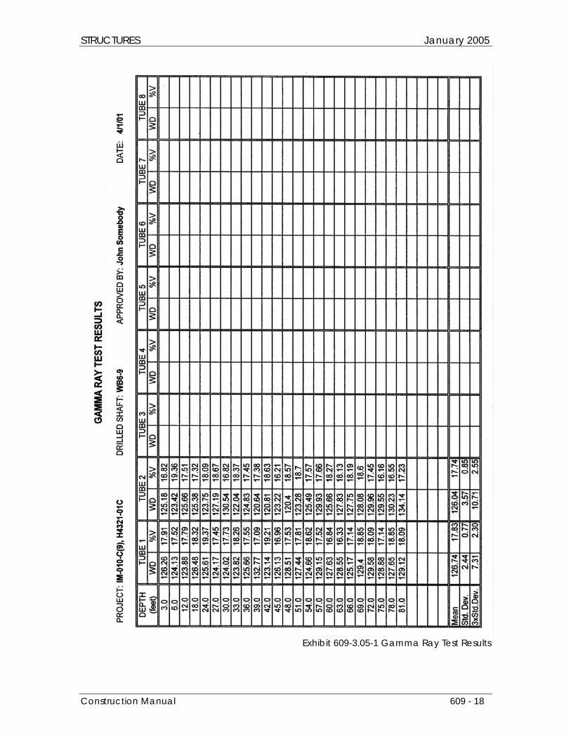
The counts for each tube are analyzed to determine the mean and the sample standard deviation (see Exhibit 609-3.05-1). Counts below the mean by more than three standard deviations are a good indication of a soil intrusion or poorly consolidated concrete around the inspection tube. When counts this low occur or when wide variations in standard deviations occur in adjacent tubes, the Resident Engineer should send the results to ADOT Geotechnical Section for further analysis.
The key to having meaningful results with the gamma ray probe is to take the measurements consistently. The 2.5 inch (65-millimeter) PVC tubes will provide the widest variations in reading especially if the tubes are warped due to the hydration heat from the concrete. Consistency is improved when:
Construction Manual 609 - 16
STRUCTURES January 2005
• the concrete has had a chance to gain strength and cool to a uniform temperature (wait at least 3 days after the pour if possible);
• the tubes are straight, with no bend and no tight fits; • the probe is positioned consistently in the tube (always in the center if possible); • the readings in each shaft are all taken during the same day with the same standard count for the
probe; and • 2 inch (50-millimeter) black steel pipe is used for tubing instead of PVC.
Cross-Hole Sonic Logging (CSL)
Unlike gamma ray testing, which measures the density of the concrete within 2 to 4 inches (50 to 100 millimeters) of the inspection tube, cross-hole sonic logging measures the density of concrete between inspection tubes. Ultrasonic pulses are emitted from a probe and measured by a receiver in an adjacent tube. Sound travels faster in denser material and sound waves lose energy as they pass through softer or less dense material. These two characteristics are used to measure the integrity concrete between each pair of tubes. Not only can the concrete between adjacent tubes be probed, but the concrete in the interior can be evaluated by placing the receiver probe in a tube diametrically opposite from the source probe.
Construction Manual 609 - 17
STRUCTURES January 2005
Exhibit 609-3.05-1 Gamma Ray Test Results
Construction Manual 609 - 18
STRUCTURES January 2005
Logging should be conducted at intervals of no less than 4 inches (100 millimeters) along each tube. Testing should be done with the source and emitter in adjacent tubes and at the same elevation. However the Inspector has the right to request testing at any specific location, at any specific interval, and using any source/receiver arrangement within the shaft where defects are suspected.
Steel tubing is preferred over PVC tubing for cross-hole sonic logging, but is not mandatory. PVC tubes can debond from the surrounding concrete rendering the test useless in that part of the shaft. Where this occurs, the Contractor will have to provide other means for testing the integrity of that portion of the shaft.
The results of cross-hole sonic logging are difficult to analyze and are beyond the scope of this manual. Test results from cross-hole sonic logging should be sent to the Geotechnical Section for analyses. Geotechnical Section can also provide field guidance to the Resident Engineer and Inspector as to what good test results should look like and when suspect results should be forwarded for review.
609-3.06 Reinforcing Steel
Section 605 of this manual provides additional information on inspecting reinforcing steel that is applicable to this Subsection.
Rebar Cages
The Project Plans will show the reinforcing steel details for each group of drilled shafts. Shop drawings for the rebar cages should be produced in accordance with Subsection 605-3.01 and sent to the Inspector for review. The Inspector should compare the shop drawings and any bar lists with the Project Plans. Any changes in how bars are spliced or how longitudinal bars are terminated at the top or bottom of the cage should be brought to the attention of the Resident Engineer and the Structural Designer. Hooks on spiral or hoop bars should be checked to ensure a tremie or pump tube can move freely through the center of the rebar cage without getting caught on any protruding steel.
The shop drawings should be approved by the Resident Engineer before any rebar cages are fabricated. Fabrication is usually done at the project site close to the holes. The cages are built on the ground giving the Inspector ample opportunity to observe the fabrication process. Rebar cages need to be checked for:
• bar sizes and grades; • proper bar spacing and bar lengths; • adequate bar clearances; • proper lap lengths for hoops, spirals, and straight bars; � overall length and width; • stiffness and stability for lifting; and • proper placement and securing of inspection tubes (when used).
For safety or constructability reasons, the Contractor may want to substitute welded splices or mechanical couplers for the lap splices shown in the Project Plans. These substitutions are permissible as long as they conform to Subsection 605-3.02. Any substitution should be at no cost to the Department. See Subsection 605-3.02 of this manual for a further discussion. When mechanical splices are used, the Inspector must use the manufacturer's instructions as a guide to inspecting the splicing operation.
Construction Manual 609 - 19
STRUCTURES January 2005
When the cages are lifted, it is important for the Inspector to look for any twisting or distortions that may have bent bars. High stress concentrations can develop in a drilled shaft when distorted cages are used. The Inspector should closely examine the rebar cage as it is lowered into the hole. If the Inspector notices significant bending or distortion of the bars that affects bar straightness, spiral pitch, bar spacing, or cage shape and diameter, the cage should be lifted from the hole and the bent bars replaced.
Drilled shafts can usually be deepened by up to 3 feet (1 meter) without having to extend the rebar cage (check the Project Plans).
Centering Devices
To construct a long lasting and durable drilled shaft, the rebar cage must be completely surrounded by an adequate cover of concrete (3 inches [75 millimeters] is usually the minimum). Centering devices are used to keep the rebar cage properly aligned in the hole until the concrete is placed. Concrete rings and plastic wheels that clip on to the spiral or hoop reinforcing are the best type of centering device. As long as they can turn freely as the cage is lowered into the hole, they will minimize the amount of loose material that falls into the hole if the cage hits the side of the excavation. The wheels should have a maximum horizontal spacing of 90 degrees with the maximum vertical spacing between 10 to 15 feet (3 to 5 meters) depending on the stiffness of the rebar cage.
The steel hair-clip type of centering device is also acceptable as long as the steel is epoxy coated in accordance with Subsection 1003-5 and placed in accordance with Subsection 605-3.03. The epoxy coating is needed to prevent the establishment of a corrosion channel from the surrounding soil to the rebar cage. Certificates of Compliance for the epoxy coating are required.
Dobie blocks are not acceptable as centering devices except for shallow sign and light foundations. When they come in contact with the sides of the excavation, the blocks often move out of position while knocking too much loose material into the excavation.
Cage Stiffeners
Rebar cages are built horizontally on the ground then lifted vertically for lowering into the hole. The cages themselves are long, slender, and flimsy. The process of lifting a cage to a vertical position can severely distort and bend portions of the rebar cage. To prevent this, Contractors will place temporary stiffeners inside the rebar cage. Sometimes they are tied to the outside of the cage. Regardless of where they are placed, stiffeners shall be removed as the cage is lowered into the hole. Stiffeners can interfere with concrete placement especially when the concrete is allowed to free fall. Outside stiffeners can provide a corrosion channel from the ground to the rebar cage. No tack welding of stiffeners to the rebar cage should be done unless the rebar cage is made of weldable reinforcing steel (ASTM A706 type).
609-3.07 Concrete Placement
(A) General
In Subsection 609-2.01 of this manual, it was stressed that drilled shaft concrete needs to be fluid. The more fluid the concrete, without risking segregation and strength loss, the better. Fluid concrete in the drilled shafts has the advantages of:
Construction Manual 609 - 20
STRUCTURES January 2005
• completely coating reinforcing steel without the need for vibration; • being able to fill any surface voids along the walls of the excavation; and • exerting an enormous hydrostatic pressure against the walls of the excavation.
With some shafts as deep as 130 feet (40 meters), it is extremely difficult to get a concrete vibrator deep enough to sufficiently vibrate the concrete around the rebar cage. Fluid concrete eliminates this problem.
For skin-friction type drilled shafts, an irregular surface between the walls of the excavation and the concrete is highly desirable. Fluid concrete will fill in any voids along the walls of the excavation no matter how irregular. The resulting irregular surface will enhance the skin friction abilities of the shaft.
Perhaps the most important advantage of highly fluid concrete is the hydrostatic pressure it exerts against the walls of the excavation. There are no upper limits placed on the rate of concrete placement for drilled shafts (the minimum is 40 feet [12 meters] per hour). In fact, the Contractor should be encouraged to pour the shaft as quickly as possible. The resulting hydrostatic pressure does several things.
First it pushes the concrete against the walls of the excavation. Not only does this help fill any surface voids, but it also compacts the surface materials. In other words, the drilled shaft concrete is pressure fitted against the sides of the excavation.
Second the hydrostatic pressure removes any loosely held material along the walls of the excavation above the concrete surface. There is a squeezing action going on as the concrete rises. The fluid and dense concrete loosens any lighter material held above. The material falls on top of the concrete and floats there until the pour is completed. This is an important phenomenon that should not be ignored by the Inspector. When drilling slurry is used, a filter cake is formed on the walls of the excavation. This cake is muddy and slippery. The fluid concrete removes this coating of filter cake eliminating any unexpected loss in skin friction due to the drilling slurry. The pressure also prevents any of the drilling slurry from mixing in with the fresh concrete.
Thus a very fluid concrete that doesn't segregate and has a long setting time is ideal for drilled shafts. Inspectors can ensure fluidity is maintained by taking many slump tests and regularly checking mixing time on the concrete tickets. When carefully controlled, adding water or a plasticizer to improve the slump is an acceptable field practice for drilled shafts.
(B) Placement in Dry Excavations
Having a clean hole is most important. The Inspector must approve the cleanliness of the hole before any steel is placed or concrete poured. During concreting, the shaft needs to be inspected at frequent intervals to be sure that there is no caving of the walls and significant contamination of the concrete.
The best time to pour a drilled shaft is immediately after the hole is cleaned and accepted by the Inspector. The rebar cage should be promptly set and the concrete poured immediately after that. This rapid sequence of events minimizes the chances of debris falling into the hole and contaminating the shaft.
In a dry hole the concrete can be placed by a concrete pump or using the chutes from the mixer trucks. There is no limit on the amount of free fall as long as the concrete does not hit anything (like the rebar cage) on the way down or scour the bottom or sides of the shaft. Any cage stiffeners or supports should be removed before pouring.
Construction Manual 609 - 21
STRUCTURES January 2005
As the concrete rises to the top of the hole, loose materials such as sand, silt, and filter cake will ride on the surface. This material mixes with the top meter of concrete. The pour needs to be continued and the excess concrete spilled until the Inspector observes fresh concrete that is relatively uncontaminated. There is no additional compensation to the Contractor when extra concrete has to be added to the hole in order to expel contaminated concrete already placed.
Regardless of how fluid the concrete looks, the top 10 feet (3 meters) of concrete poured in a dry hole and the top 5 feet (1.5 meters) poured in a wet hole needs to be vibrated, but only after all water, slurry, and contaminated material has been removed. These areas are the most likely to have voids around the steel since they do not benefit from any hydrostatic pressure exerted from concrete above.
(C) Placement under Slurry or Water
When concrete is placed in water or slurry, the concrete needs to be placed the same day as the excavation is completed. This reduces the risk of a major soil collapse if the hole is left open too long.
When placing concrete in the water- or slurry-filled shaft, a tremie is used to deliver the concrete to the bottom of the shaft. The tremie cannot be made of aluminum since aluminum reacts adversely with fresh concrete.
The purpose of the tremie is to keep the fluid concrete from mixing with the water or slurry in the hole and to deliver the concrete to the bottom of the shaft in an uncontaminated state. A valve, sealable cap, or plug is placed in the tremie tube to prevent water or slurry from entering.
The keys to successful concrete placement with a tremie include:
• The initial placement of the tremie at the bottom of the tube should be in the range of 2 to 12 inches (50 to 300 millimeters) from the bottom of the hole.
• There should be a quick, uninterrupted, initial flow of concrete that buries the tip of the tremie in at least 5 feet (1.5 meters) of fresh concrete.
• There should always be a head of concrete in the tremie tube itself of at least 4 feet (1.2 meters) higher than the surface of the slurry or water.
• The concrete must have a slump of at least 8 inches (200 millimeters) with no segregation and no cement balls.
• Lifting the tremie as the concrete rises prevents segregation, but be especially careful to monitor the depth of the concrete versus the depth of the tremie so that there is never any chance that the end of the tremie will pull out of the fresh concrete.
Strict adherence to these practices will prevent the concrete from mixing with the water or slurry in the hole—the primary objective of pouring with a tremie.
If everything works properly, the concrete cleans the slurry off the reinforcing as it rises up the shaft. The top layer of concrete catches any slough or filter cake from the sides of the shaft. The pumping continues after the concrete reaches the top of the shaft until all the contaminated concrete has been ejected.
When pumping off the ejected slurry, especially when the top of the shaft has been widened appreciably, care must be taken to not allow the water to flow fast enough to wash cement and fines from the concrete.
Construction Manual 609 - 22
STRUCTURES January 2005
609-3.08 Casing Removal
Temporary Casing
Temporary casing functions as a means for keeping a hole opened while it is excavated and filled with concrete. It can also be used as a means for stabilizing ground around the excavation to reduce the amount of overbreak (extra concrete) or as a safety barrier for people working in and around the excavation. Temporary casing is usually made of smooth rolled steel plates.
Permanent casing reduces the skin friction developed between the shaft and the surrounding soil to zero. This is why temporary casing needs to be removed and any casing left by the Contractor needs the prior approval of the Foundation Designer. If there is a loss in drilled shaft capacity due to casing left in the hole, the Contractor is responsible for placing additional drilled shafts and altering the substructure as necessary to meet the load carrying requirements of the foundation.
Drilling Contractors and the Department do not like to leave temporary casings in a completed drilled shaft. Drilling Contractors have to buy a replacement casing and the Department then has to determine whether the temporary casing reduces skin friction around the shaft sufficiently enough to warrant remedial actions.
In order to encourage a win-win outcome with temporary casing, Inspectors should examine temporary casing for any characteristics that would cause them to get stuck in the hole. This could include accumulations of mud or dried concrete, imperfections on the casing surface, too much rust, or anything that detracts from the smooth, clean appearance that a temporary casing should have. Sometimes temporary casing is telescoped. This means a large surface casing is above a smaller subsurface casing which may be above a deeper and smaller temporary casing. There is usually overlap between these casings, sometimes to 6 feet (2 meters) in length. The material in the overlap between the casings is usually loose soil or slurry. When the shaft concrete is poured, the smaller casing needs to get pulled before the concrete reaches the top of that casing. If this is not done, concrete will spill over and fall into the gap between the smaller and larger casing. The concrete then mixes with the loose soil or slurry between the two casings, forming a permanent zone of weakness in the shaft. This can render the shaft defective.
Casing Removal
When removing casing during a concrete pour, the Inspector needs to keep four points in mind:
1. There must be at least 5 feet (1.5 meters) of concrete head in the tremie pipe above the surface of the concrete as the casing is being removed (except near the top of the shaft). 2. The concrete surface must always be at least 5 feet (1.5 meters) above the bottom of the casing as the casing is being removed. 3. The slump of the concrete must be at least 4 inches (100 millimeters). 4. The casing should be slowly removed from the hole to prevent an upward movement of the concrete and the rebar cage. The first two points ensure that there is at least 10 feet (3 meters) of concrete head pressure at the bottom of the casing. Head pressure is needed to keep soil, water, or slurry from mixing with the concrete that discharge from the bottom of the casing as the casing is pulled.
Construction Manual 609 - 23
STRUCTURES January 2005
When deep casing is used (30 feet [10 meters] or more), the hydrostatic pressure exerted by water or slurry in the excavation can be substantial. The 10 feet (3 meters) of concrete head required by the Standard Specifications may be insufficient to offset the pressure exerted by the water or slurry. The minimum head requirements as the casing is pulled should be increased by the Resident Engineer based on the following formula:
Minimum Total Concrete Head (feet) =
4 x total slurry or water head outside of casing (feet) x density of water or slurry (lb/cf) Density of concrete (lb/cf)
or,
Minimum Total Concrete Head (meters) =
1.2 x total slurry or water head outside of casing (m) x density of water or slurry (kg/m3) Density of concrete (kg/m3)
The concrete head and water or slurry head are both measured from the bottom of the casing. Slump is another important concrete property that must be closely monitored when a casing is pulled. If the Contractor waits too long to pull the casing and the concrete begins to lose slump, three things can happen:
1. the concrete sets up enough such that the casing cannot be removed;
2. the concrete sets and comes up with the casing (usually lifting and twisting the rebar cage out of position); or
3. the concrete cannot expand sufficiently enough to fill the voids and exert a positive pressure against
the walls of the excavation. Any one of these is potentially devastating to the integrity of the drilled shaft. Inspectors must keep a close eye on slump and set time for the concrete that is already down in the hole. The Contractor can use super-plasticizers and retarders when the concrete is batched to provide more flexibility on when the casing needs to be removed.
Even when there is sufficient concrete head in the casing and the slump is okay, the Contractor must still be careful in how the casing is removed. Problems with casing removal have produced the largest number and worst type of drilled shaft defects. The Inspector should closely monitor casing removal for any upward movement or racking of the rebar cage. A level with a target placed on the cage can be used to measure movement. However this can only be done before and after removal of the casing.
Monitoring rebar cage movement during actual casing removal is extremely difficult. The Inspector can monitor the position of the crane jib holding the cage for some signs of cage movement. However the best thing for the Inspector to do is ensure that good casing removal techniques (slow withdrawal, vibration assistance, casing tapping, etc.) are used. Casing removal is a topic that must be thoroughly discussed at any drilled shaft preconstruction meeting and should be included in the Contractor's installation plan.
Construction Manual 609 - 24
STRUCTURES January 2005
609-4 & 5 Method of Measurement & Basis of Payment
Drilled shafts are not usually part of a lump sum structure, but paid separately on a linear meter basis for the actual length placed. Drilled shafts may be extended up to 3 feet (1 meter) without having to lengthen the rebar cage.
When drilled shafts are shortened and the Contractor has to cut the rebar cage, the Department will purchase the wasted rebar from the Contractor under the provisions of Subsection 109.04. Labor and equipment used for assembling that portion of the wasted rebar cage can also be included. The rebar becomes the property of the Department and should be disposed of in accordance with Subsection 603-3.04 of this manual.
Rock Sockets
Subsection 609-3.01 of this manual (under Soil Identification) establishes the procedure for determining when bedrock has been reached for rock socket purposes. The following attempts to more narrowly define the top of rock socket elevation for payment purposes. Rock sockets, when specified and paid for separately, are measured from the top of bedrock elevation to the bottom of the shaft. The question that invariably arises on each project is, “Where exactly does the bedrock begin?” When highly fissured or decomposed rock many meters deep lies on top of bedrock, the boundary can become obscured.
In Subsection 609-6.01 of this manual, the Geotechnical Engineer for the project makes the initial determination in the field when suitable bedrock is reached. The Resident Engineer or the Inspector then makes subsequent determinations and contacts the Geotechnical Engineer only when there are bedrock identification problems. For payment purposes, the Department considers the top of the rock socket to be the elevation at which suitable bedrock is reached. This means regardless of the difficulty the drilling Contractor has in reaching suitable bedrock, the separate measurement for rock sockets does not begin until a suitable rock has been reached.
Here is a procedure the Inspectors should use for determining the elevation at which the rock socket begins:
1. As the Contractor advances the hole, fractured and decomposed rock will begin showing up on the auger flights. When the auger trimmings contain predominantly rock fractured by the auger (80% or more), then this is a good indication that the top of the rock socket has been reached. If the rock is hard, a rock auger may be needed to fracture the rock. Rock fractured by drilling tools will have sharp edges and fractured faces that look fresh. Decomposed rock will have rounded edges with dull fractured faces. The Inspector should observe a corresponding increase in both engine noise and amount of down pressure (crowd) applied to auger.
2. When the Inspector is convinced based on the auger trimmings that the rock formation is suitable to
begin the rock socket, the Inspector should measure and record the depth of the hole. The Inspector can adjust the elevation upward if the auger has clearly penetrated into suitable rock before the depth measurement is made.
3. From this point on, drilling begins for payment under the rock socket item. The Inspector should
measure and record the bottom of rock socket elevation, then check the rock socket length to ensure it meets the minimum shown on the Project Plans.
Construction Manual 609 - 25