6044/6036 OWNER/OPERATOR MANUAL - Castle and Son · Pettibone Michigan, L.L.C. OWNER/OPERATOR...
101
Page 1 Pettibone Michigan, L.L.C. OWNER/OPERATOR MANUAL MODEL 6044/6036 6044/6036 OWNER/OPERATOR MANUAL Copyright March 1999 Pettibone Michigan, L.L.C. Technical Publications Baraga, MI The information and illustrations in this manual have been approved as accurate at the time of printing. However, the manual may contain information on options not present on your machine. Pettibone Michigan L.L.C. reserves the right to make changes and improvements in its product at anytime without notice or obligation. This manual is to remain with the unit at all times. The storage compartment for this manual is located in the operators cab behind the seat. Contact Pettibone Michigan or an authorized dealer for replacement manuals.
Transcript of 6044/6036 OWNER/OPERATOR MANUAL - Castle and Son · Pettibone Michigan, L.L.C. OWNER/OPERATOR...
Page 1Pettibone Michigan, L.L.C. OWNER/OPERATOR MANUAL MODEL 6044/6036
6044/6036 OWNER/OPERATOR MANUAL
Copyright March 1999Pettibone Michigan, L.L.C.
Technical PublicationsBaraga, MI
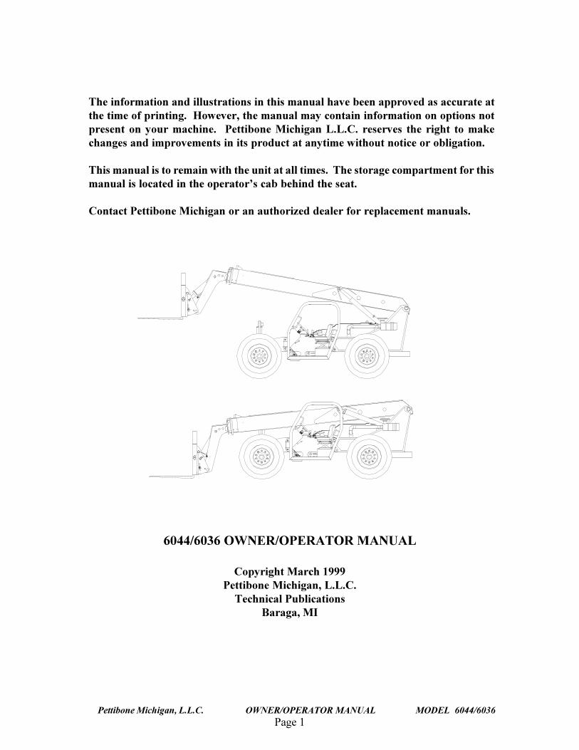
The information and illustrations in this manual have been approved as accurate atthe time of printing. However, the manual may contain information on options notpresent on your machine. Pettibone Michigan L.L.C. reserves the right to makechanges and improvements in its product at anytime without notice or obligation.
This manual is to remain with the unit at all times. The storage compartment for thismanual is located in the operator�s cab behind the seat.
Contact Pettibone Michigan or an authorized dealer for replacement manuals.
Page 2
TRAVERSE LIFT
Pettibone Michigan, L.L.C. OWNER/OPERATOR MANUAL MODEL 6044/6036
continued on next page
6044 Table of Contents
INTRODUCTION .................................................................................................................................... 6PREFACE................................................................................................................................................... 6
CALIFORNIA PROPOSITION 65 WARNING ................................................................................. 7HYDRAULIC PRESSURE WARNING SHEET ...................................................................................... 8MODEL 6044/6036 .................................................................................................................................... 8SAFETY .................................................................................................................................................... 9SAFETY RULES ....................................................................................................................................... 9
EXPLANATION OF � WARNINGS� ........................................................................................... 9
EXPLANATION OF � CAUTIONS� ............................................................................................. 9 EXPLANATION OF �NOTES � .............................................................................................................. 9BEFORE OPERATION ........................................................................................................................... 10MACHINE OPERATION ........................................................................................................................ 11TRANSPORTING SAFELY ................................................................................................................... 12PARKING THE MACHINE .................................................................................................................... 12BURN PREVENTION ............................................................................................................................. 12FIRE OR EXPLOSION PREVENTION ................................................................................................. 13MAINTENANCE ..................................................................................................................................... 14SAFETY WHILE SERVICING THE MACHINE .................................................................................. 14MAINTENANCE PROCEDURES .......................................................................................................... 14 SAFETY .................................................................................................................................................. 16DECAL LOCATIONS ............................................................................................................................. 16DECALS .................................................................................................................................................. 16
6044, Left Side View of Machine Decals .......................................................................................... 17Decals Located Behind Seat ............................................................................................................... 18Hydraulic and Fuel Tank Decals ........................................................................................................ 21
MATERIAL SAFETY DATA SHEETS (MSDS)................................................................................... 40IDENTIFICATION NUMBERS .............................................................................................................. 40EQUIPMENT.......................................................................................................................................... 42MACHINE INSPECTION AND DELIVERY REPORT ........................................................................ 42SAFETY ................................................................................................................................................... 42RIGHT, LEFT, FRONT AND REAR OF MACHINE ............................................................................ 43
EXPLANATION OF � WARNINGS� ......................................................................................... 44
EXPLANATION OF � CAUTIONS� ........................................................................................... 44 EXPLANATION OF �NOTES � ............................................................................................................ 44SAFETY PRECAUTIONS ...................................................................................................................... 44
INTRODUCTION .............................................................................................................................. 46IDENTIFICATION .................................................................................................................................. 46FORKLIFT IDENTIFICATION PLATE ................................................................................................ 46ENGINE IDENTIFICATION PLATE .................................................................................................... 46
Page 3Pettibone Michigan, L.L.C. OWNER/OPERATOR MANUAL MODEL 6044/6036
(Continued on next page)
continued from previous page
TRANSMISSION IDENTIFICATION PLATE ...................................................................................... 46AXLE IDENTIFICATION PLATE LOCATION ................................................................................... 46EQUIPMENT DESCRIPTION ............................................................................................................... 48FORKLIFT DESCRIPTION .................................................................................................................... 48STANDARD ENGINE DESCRIPTION ................................................................................................. 48TRANSMISSION DESCRIPTION ........................................................................................................ 48AXLE DESCRIPTION ............................................................................................................................ 48OPTIONS ................................................................................................................................................. 48SPECIFICATIONS .................................................................................................................................. 48PREOPERATIONAL CHECKS AND SERVICES ................................................................................ 48TABLE II. SPECIFICATIONS ............................................................................................................... 49OPERATION .......................................................................................................................................... 51
Entering the Operator�s Compartment ............................................................................................... 51Operator�s Seat ................................................................................................................................... 51Seat Suspension Adjustment (optional) .............................................................................................. 51Arm Rest ............................................................................................................................................. 51Seat Belt .............................................................................................................................................. 52Instrument Panel ................................................................................................................................. 53Fuel Gauge .......................................................................................................................................... 53Engine Coolant Temperature Gauge .................................................................................................. 53Engine Coolant Temperature Warning Light (Optional) ................................................................... 53Inclinometer ........................................................................................................................................ 55Parking Brake Switch ......................................................................................................................... 55Clutch Cut-off Switch ........................................................................................................................ 55Axle Lock Warning Light .................................................................................................................. 55 Brake Oil Pressure Warning Light .................................................................................................... 55Park Brake Indicator Light ................................................................................................................. 55Low Voltage Warning Light .............................................................................................................. 55Engine Oil Pressure Warning Light ................................................................................................... 56Ignition Switch ................................................................................................................................... 56Steering Selector ................................................................................................................................. 56Hydraulic Controls ............................................................................................................................. 57Throttle and Brake Controls ............................................................................................................... 58Transmission Controls ........................................................................................................................ 59
CHECK TRANSMISSION OIL .............................................................................................................. 60CHECK HYDRAULIC FLUID LEVEL ................................................................................................. 60TIRES AND RIMS .................................................................................................................................. 61INSPECTION FOR LEAKS .................................................................................................................... 61GENERAL INSPECTION ....................................................................................................................... 62GAUGES AND INDICATORS ............................................................................................................... 62HYDRAULIC FLUID LEVEL ................................................................................................................ 62CHANGES IN PERFORMANCE ........................................................................................................... 62OPERATING INSTRUCTIONS ............................................................................................................. 62TABLE IV. TIRE PRESSURES ............................................................................................................. 62OPERATIONAL CHECKS & SERVICES ............................................................................................. 63
Page 4
TRAVERSE LIFT
Pettibone Michigan, L.L.C. OWNER/OPERATOR MANUAL MODEL 6044/6036
continued from previous page
STARTUP AND DRIVING ..................................................................................................................... 63RAISING THE LOAD ............................................................................................................................. 67TRANSPORTING THE LOAD............................................................................................................... 68MAINTENANCE .................................................................................................................................... 69 INTRODUCTION .................................................................................................................................. 69TABLE V. SCHEDULED MAINTENANCE ........................................................................................ 69TABLE VI. FLUIDS AND LUBRICANTS ........................................................................................... 71 LUBRICATION ...................................................................................................................................... 73TABLE VII. LUBRICATION POINTS ................................................................................................. 75TROUBLESHOOTING ........................................................................................................................... 76HOW TO USE TROUBLESHOOTING TABLES ................................................................................. 76TABLE VIII. ENGINE TROUBLESHOOTING ................................................................................... 76TABLE IX. ENGINE ELECTRICAL TROUBLESHOOTING ............................................................. 80TABLE X. TRANSMISSION TROUBLESHOOTING......................................................................... 81TABLE XI. HYDRAULIC SYSTEM TROUBLESHOOTING ............................................................. 83
MAIN DIRECTIONAL VALVE TROUBLESHOOTING ............................................................... 85REMOTE CONTROL (JOYSTICK) VALVE TROUBLESHOOTING .......................................... 87ACCUMULATOR CHARGING VALVE TROUBLESHOOTING................................................. 88FRAME TILT CYLINDER TROUBLESHOOTING ....................................................................... 89FORK TILT CYLINDER TROUBLESHOOTING .......................................................................... 90EXTENSION CYLINDER TROUBLESHOOTING ........................................................................ 91
REPLACE FUEL FILTER ELEMENT................................................................................................... 92BLEEDING THE FUEL SYSTEM ......................................................................................................... 92MAINTENANCE PROCEDURES .......................................................................................................... 92SERVICE AIR CLEANER ...................................................................................................................... 94DRAIN AND REFILL COOLING SYSTEM ......................................................................................... 95THERMOSTAT TEST ............................................................................................................................ 96FUSE REPLACEMENT .......................................................................................................................... 98ENGINE OIL CHANGE .......................................................................................................................... 98 TRANSMISSION OIL CHANGE ......................................................................................................... 99TRANSMISSION FILTER ELEMENT REPLACEMENT .................................................................. 100AXLE LUBRICANT CHANGE ............................................................................................................ 100SUMMARY............................................................................................................................................ 101

Page 5Pettibone Michigan, L.L.C. OWNER/OPERATOR MANUAL MODEL 6044/6036
NOTES
THIS PAGEINTENTIONALLY
LEFT BLANK
Page 6
TRAVERSE LIFT
Pettibone Michigan, L.L.C. OWNER/OPERATOR MANUAL MODEL 6044/6036
PREFACE
This manual instructs the owner/operator in the correct operation of the Pettibone Michigan Model6044 forklift. The location and operation of all controls are explained in this manual. It also containslubrication tables, which indicate the recommended servicing intervals for all fluids and greasedcomponents.
This manual should be considered a permanent part of your vehicle. It should stay with the vehicle, ifsold, to provide the next owner with required operating instructions.
All instructions, illustrations and specifications contained herein are based upon the latest productinformation available at the time of printing. Pettibone Michigan reserves the right to changespecifications without prior notice in order to follow its policy of constantly striving to manufacture abetter product without incurring any liability to provide these new features on any units previouslymanufactured.
Be sure your dealer has returned the Warranty Registration Form for your machine to PettiboneMichigan. This form must be filled out properly in initiate warranty coverage on the machine. Inaddition, your dealer will fill out a Machine Inspection Report, which the owner should sign. Also, a30-day check up is recommended as defined in this manual. If a problem occurs with your machineduring the warranty period, contact your dealer immediately. Do not continue to operate the machineuntil authorized.
INTRODUCTION
Page 7Pettibone Michigan, L.L.C. OWNER/OPERATOR MANUAL MODEL 6044/6036
CALIFORNIA PROPOSITION 65 WARNING
Diesel engine exhaust and some of itsconstituents are known to the State of
California to cause cancer, birthdefects, and other reproductive harm
Page 8
TRAVERSE LIFT
Pettibone Michigan, L.L.C. OWNER/OPERATOR MANUAL MODEL 6044/6036
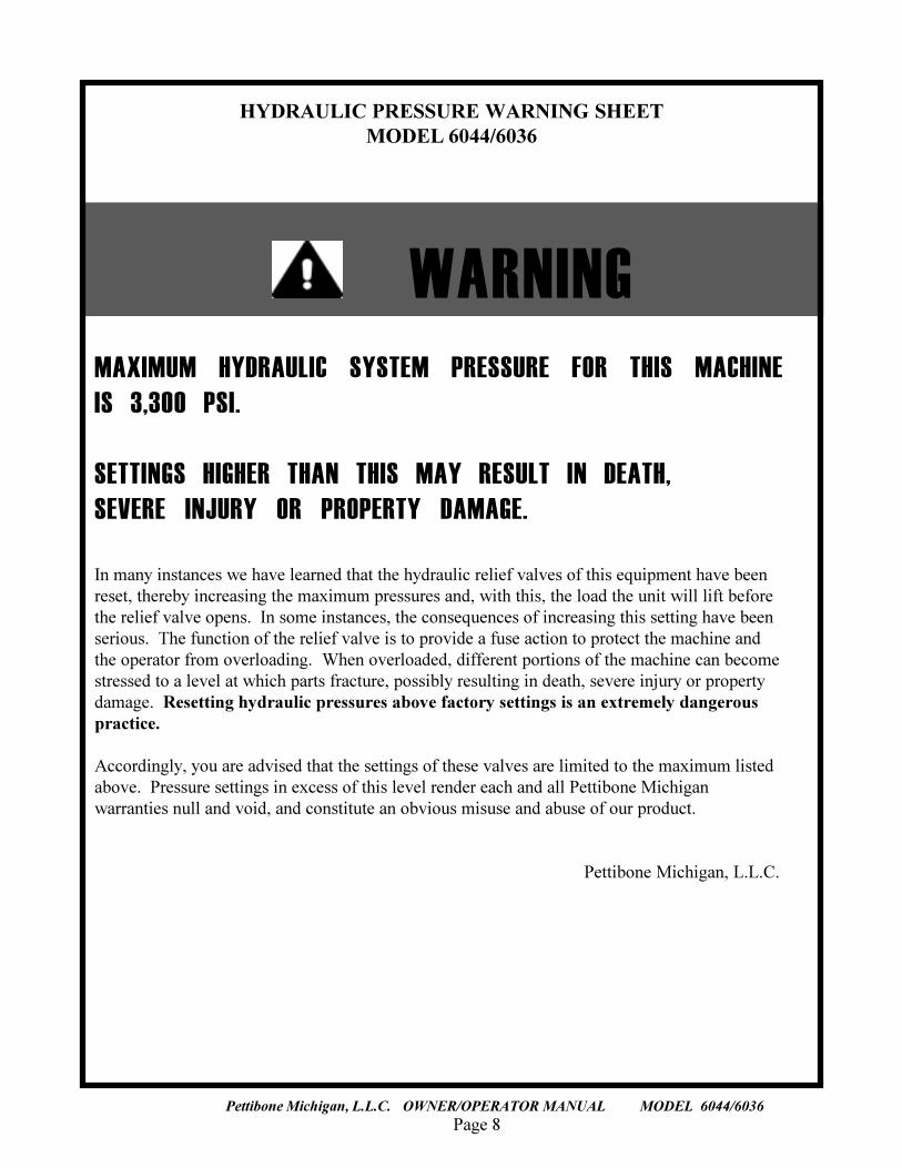
HYDRAULIC PRESSURE WARNING SHEETMODEL 6044/6036
MAXIMUM HYDRAULIC SYSTEM PRESSURE FOR THIS MACHINEIS 3,300 PSI.
SETTINGS HIGHER THAN THIS MAY RESULT IN DEATH,SEVERE INJURY OR PROPERTY DAMAGE.
In many instances we have learned that the hydraulic relief valves of this equipment have beenreset, thereby increasing the maximum pressures and, with this, the load the unit will lift beforethe relief valve opens. In some instances, the consequences of increasing this setting have beenserious. The function of the relief valve is to provide a fuse action to protect the machine andthe operator from overloading. When overloaded, different portions of the machine can becomestressed to a level at which parts fracture, possibly resulting in death, severe injury or propertydamage. Resetting hydraulic pressures above factory settings is an extremely dangerouspractice.
Accordingly, you are advised that the settings of these valves are limited to the maximum listedabove. Pressure settings in excess of this level render each and all Pettibone Michiganwarranties null and void, and constitute an obvious misuse and abuse of our product.
Pettibone Michigan, L.L.C.
WARNING
Page 9Pettibone Michigan, L.L.C. OWNER/OPERATOR MANUAL MODEL 6044/6036
SAFETY RULES
Most accidents involving machine operation and maintenance can be avoided by following basic rulesand precautions. Read and understand all the safety messages in this manual, and the safety signs onthe machine before operating or servicing the machine. See the dealer for any questions. Failure toread and follow these instructions could result in death, serious injury or damage to the ma-chine.
READ THIS MANUAL COMPLETELY and be sure to understand the characteristics of speed,stability, and steering of this machine. Do not remove this manual from the machine. This manualmust remain with the machine at all times. The manual storage box is located inside the operator�scompartment, behind the operator�s seat. See your dealer or contact Pettibone Michigan for additionalmanuals.
The safety information given in this manual does not replace safety codes, insurance regulations, orfederal, state and local laws. Be sure the machine has the correct equipment according to these rules orlaws.
IMPORTANT: Safety messages in this section point out situations that can be encountered duringthe normal operation and maintenance of your machine. These safety messages also give possibleways of dealing with these conditions.
Additional safety messages are used in the text of the manual to show specific safety hazards.
EXPLANATION OF � DANGER�Denotes a hazard which WILL result in death or injury if proper precautions are not taken.
EXPLANATION OF � WARNINGS�A warning is a statement that informs the reader of a condition that is unsafe to personnel. Failure toheed a warning may result in DEATH or INJURY to personnel.
EXPLANATION OF � CAUTIONS�Cautions are provided as statements, which identify conditions and/or practices that could result inproperty damage or damage to the equipment.
EXPLANATION OF �NOTES �
Notes are statements that simply provide additional information.
SAFETY
Page 10
TRAVERSE LIFT
Pettibone Michigan, L.L.C. OWNER/OPERATOR MANUAL MODEL 6044/6036
BEFORE OPERATION
• Avoid loose fitting clothing, loose or uncovered long hair, jewelry or loose personal articles.
• Different jobs will require different protective equipment. Items such as hard hats, protectiveshoes, heavy gloves, reflector type vests, respirators, and ear protection may be required. Knowand use the equipment that is required before starting the job.
• Be prepared for emergencies. Always have a first aid kit and a good fire extinguisher. Knowhow to use both.
• Know the hand signals used on the job. Follow the instructions of the flag man, signs, etc.
• Check that all guards and covers are installed correctly.
• Foreign material or grease on the step or hand rail can cause an accident. Keep the step and handrail clean.
• Before operating at night, check that all lamps illuminate.
• Know the rules, laws and safety equipment necessary for transporting this machine on road orhighway.
• Before starting the engine, walk around the machine and check for oil or fluid leaks. Replace allbroken or missing parts and do the required lubrication and maintenance as shown in this manual.Clean all trash and debris from the machine.
• Always face the machine and use the hand rail and step when climbing aboard. Do not rush.
• Remove all loose objects from the operator�s compartment and from the machine. Loose objectscan jam controls and cause accidents.
• Before starting the engine, always properly fasten and securely tighten the seat belt, and alwayskeep the seat belt fastened while operating the machine. Failure to do so could result in deathor serious injury.
• Engine exhaust fumes can cause death. If you operate this machine in an enclosed area, use goodventilation to replace the exhaust fumes with fresh air.
• Make sure all persons are away from the machine and give a warning before starting the engine.
Page 11Pettibone Michigan, L.L.C. OWNER/OPERATOR MANUAL MODEL 6044/6036
MACHINE OPERATION
• Check all controls in a clear area and make sure the machine is operating correctly.
• Do not allow other persons to ride on the machine. Other persons can fall or can cause an accident.
� Do not use the machine to lift personnel or to lift any type of personnel carrier, including platforms.The machine operator may not have control over such a carrier device, which could result inserious injury or death.
• Dust, fog, smoke, etc., can decrease your vision and cause an accident. Stop the machine or de-crease the speed until everything can be seen.
• Contact with high voltage power lines, underground cables, etc., can cause serious injury or deathfrom electrocution.
NOTEBefore driving or operating in an area with high voltage lines or cables, HAVE THEPOWER DISCONNECTED OR KEEP A SAFE WORKING DISTANCE from the lines orcables. Know the safe working distance from the high voltage power equipment andobserve federal, state/provincial, or local safety codes or regulations that apply to the jobsite.
• Electrical cables, gas pipes, water pipes, sewers, or other underground objects can cause death orserious injury. Learn the location of underground hazards before operating the machine in a newarea.
• If this machine rolls over, death or serious injury may occur. Determine if weather, road, or earthconditions will permit safe operation on a hill, ramp, or rough ground.
• Stay away from hazardous areas such as ditches, overhangs, etc. Walk around the work area beforestarting the forklift and look for hazards.
• Be alert and always know the location of all workers in the area. Keep all other persons completelyaway from the machine. Serious injury or death can result if these instructions are not followed.
• Operate the machine controls from the operator�s seat only.
• Keep the forks low when moving around the work area and be careful when raising the load.
Page 12
TRAVERSE LIFT
Pettibone Michigan, L.L.C. OWNER/OPERATOR MANUAL MODEL 6044/6036
• Before operating the equipment where visibility is reduced, such as next to a building, installsafety markers to warn others of possible danger.
TRANSPORTING SAFELY
NOTEWhen correctly loaded on the flatbed of a tractor-trailer, this machine isdesigned to be transported between local work sites.
• Know which warnings must be placed on machine for highway travel and whether an escort isneeded.
• Flag attachment on furthest projection of machine for safety.
• Know measurements of machine when mounted on truck. Be sure machine is within properlimits for highway transporting.
• Become familiar with public laws and ordinances affecting driving on public roads with amounted machine. Check route for clearance. Check bridges for weight limits.
• Always shut down machine engine when transporting, even over short distances, and never rideon machine while transporting. Serious injury or death can result if these instructions are notfollowed.
• Do not put chains over or against hydraulic lines or hoses.
• Always use tape or cap exhaust pipe to prevent air from spinning turbocharger while vehicle istransported at highway speeds. The turbochargers depend upon engine oil pressure to lubricateshaft bearings and may be damaged if spun dry. BE SURE TO REMOVE TAPE AFTERTRANSPORTING OR BEFORE STARTING ENGINE.
PARKING THE MACHINE
• When parking the machine and before leaving the operator�s seat, engage the parking brake byflipping the switch located on the right side of the dashboard.
• Always face the machine and use the hand rail and step when getting off. Do not rush and do notjump from the machine.
BURN PREVENTION
• Battery acid causes severe burns. Batteries contain sulfuric acid. Avoid contact with skin, eyes orclothing. Antidote- EXTERNAL: Flush with water. INTERNAL: Drink large quantities of water
continued on following page
Page 13Pettibone Michigan, L.L.C. OWNER/OPERATOR MANUAL MODEL 6044/6036
or milk. Follow with milk of magnesia, beaten egg or vegetable oil. Call a doctor immediately.EYE: Flush with water for 15 minutes and get prompt medical attention.
• If the battery electrolyte freezes, the battery may explode if, (1) battery charge is attempted, or(2) trying to jump start the engine. To prevent the battery electrolyte from freezing, keep thebattery at full charge.
• Hot coolant can spray out when the radiator cap is removed. To remove the radiator cap, let thecooling system cool, turn to the first notch, wait until the pressure is released, then remove theradiator cap.
FIRE OR EXPLOSION PREVENTION
• Sparks or flame can cause the hydrogen gas in a battery to explode. To prevent an explosion,when disconnecting the battery cables, disconnect the negative (-) cable first. When connectingbattery cables, connect the negative (-) cable last. When connecting jumper cables to start theengine, connect the negative (-) cable last and disconnect the negative (-) cable first after theengine starts.
• Do not short circuit the battery posts with metal items.
• Do not weld, grind, or smoke near a battery.
• Sparks from the electrical system or engine exhaust can cause an explosion and fire. Before youoperate this machine in an area with flammable dust or vapors, use good ventilation to removethe flammable dust or vapors.
• Engine fuel can cause an explosion or fire. Do not fill the fuel tank with the engine running ornear open flames or sparks.
• Use nonflammable cleaning solvent to clean parts.
• Fire can cause injury or death. Always have a fire extinguisher near or on the machine. Makecertain the fire extinguisher is serviced according to the manufacturer�s instructions.
• If a fire extinguisher has been used, always recharge or replace the fire extinguisher beforeoperating the machine.
• Remove all trash or debris from the machine each day. Especially check the engine area andexhaust system.
• Starting fluid (ether) can cause death or serious injury. Do not inhale starting fluid vapors.Wear face protection when removing or installing a starting fluid container or when using aerosolspray starting fluid. Use starting fluid according to the instructions in this manual.
Page 14
TRAVERSE LIFT
Pettibone Michigan, L.L.C. OWNER/OPERATOR MANUAL MODEL 6044/6036
• If the machine has an oil, fuel, or hydraulic leak, always repair the leak and clean the area beforeoperating.
• Keep the cooling system clean and maintain the correct coolant level.
• Check the electrical system for loose connections or frayed insulation. Repair or replace the loose ordamaged parts.
• Before welding or using a torch on the machine, clean the entire machine to reduce risk of firehazard.
WARNINGDo not weld on any structural member unless specifically authorized byPettibone Michigan. Any unauthorized welding will void the warranty andmay cause death, severe injury or damage to the equipment.
MAINTENANCESAFETY WHILE SERVICING THE MACHINE
The following section gives suggested guidelines for operational maintenance on your machine. Itis not intended for use as a service manual.
Check the Hour Meter regularly to determine when the machine needs periodic maintenance. In severeconditions (extreme dust, heat, cold, humidity, etc.) you will need to service your machine more often.Your experience may dictate a more severe servicing program.
Safety while servicing machine is the owner�s responsibility. Only qualified and authorizedpersonnel should be permitted to maintain, repair, adjust and inspect the machine.
Read and understand warnings and safety precautions in the �SAFETY� section and elsewhere in thismanual before doing any service on machine. The following precautions should be used as a reminderto safe servicing.
WARNINGImproper service or repair can cause death, serious injury and/ or damage tothe equipment. Refer to the service manual for proper maintenance procedures,including any supplied component manuals.
MAINTENANCE PROCEDURES
• Before servicing the machine, put a DO NOT OPERATE tag on the instrument panel.
• Lower boom to ground, shut down machine to a zero energy state, remove key from ignition andallow machine to cool before beginning work.
continued on following page
Page 15Pettibone Michigan, L.L.C. OWNER/OPERATOR MANUAL MODEL 6044/6036
� Relieve all hydraulic pressure in the hydraulic reservoir before breaking any hydraulic connection orbefore opening the reservoir access cover.
� Disconnect battery.
WARNINGIf it is necessary to have the engine running while servicing the machine,have another person assist with the procedure. Do not leave the operator�sseat with the engine running. Failure to follow these precautions could resultin death, serious injury or damage to the equipment.
� Do not support the machine, the boom, or any attachments on cinder blocks, hollow tiles, or propsthat may crumble under a load. Do not work under a machine that is supported solely by a jack.
� Remove, block or guard against body contact with all other sources of hazardous pressure,temperature, electricity or machine motion.
� Make sure that boom and attachments are grounded to avoid electrical shock.
� Do not make any modifications to this machine or weld on any structural member unlessspecifically authorized by Pettibone Michigan. Any unauthorized modifications made or weldingwill void the warranty and may cause death, serious injury or damage to the equipment.
WARNINGUnauthorized modifications to this machine can cause injury or death.Refer to your authorized dealer or Pettibone Michigan before modifying themachine.
• Metal chips or debris can cause eye injury. Always wear eye or face protection when using a hammeron this machine. Use a hammer with a soft face, such as brass, to drive hardened pins.
• Hydraulic fluid or grease injected into skin can cause severe injury or death. Keep hands and bodyaway from any pressurized leak. If fluid is injected into skin, see a doctor immediately.
• When servicing this machine, always wear safety protection, including but not limited to hard hat,workshoes and safety glasses.
� Don�t leave loose tools and rags on the machine. Make sure that all walking and climbing surfacesare clean.
� Handle fuel carefully. Do not smoke while filling fuel tank or working near fuel. Refer to the�Lubricants� table when replacing oils, fluids or filling fuel tank.
Page 16
TRAVERSE LIFT
Pettibone Michigan, L.L.C. OWNER/OPERATOR MANUAL MODEL 6044/6036
SAFETYThe decals pictured in this section were accurate at this publication was printed. Pettibone Michiganreserves the right to add additional safety decals to the machine as necessary to ensure operator safety. Itis the operator�s responsibility to follow the instruction decals on the particular machine being operated.
WARNINGInjury or death can result if safety decals are not followed. Immedi-ately replace any missing or damaged safety decal(s), and keep allsafety decals clean and legible. Contact an authorized dealer orPettibone Michigan for new safety decals.
• Be sure to read all safety decals and all instruction decals. Check these decals daily. Keep these decalsclean.
• To clean the decals, use only a cloth, water, and soap. Do not use solvents, gasoline, etc.
• Replace decals if damaged, missing, or unreadable. If a decal is on a part that is replaced, install anew decal on the replacement part.
DECAL LOCATIONS
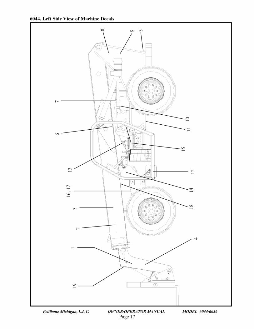
Table I., �MACHINE DECALS� consists of a list of decals located on the 6044 forklift. The table isdivided into five columns:
� ITEM#: gives the number by which the particular decal is identified in Figures 1a. and 1b., �DecalLocations�.� PART#: gives number of that decal the Pettibone Michigan part number for reordering purposes.� DESCRIPTION: gives a description of the decal.� SERIAL # / DATE OF CHANGE: references if the decal was added to or changed on a particularmachine.� QTY. : lists the total number of that particular decal needed for the machine.
Full-size illustrations of these decals, along with expanded descriptions of each decal�s location, areshown on pages 23-39 following Table I.
DECALS
Page 17Pettibone Michigan, L.L.C. OWNER/OPERATOR MANUAL MODEL 6044/6036
6044, Left Side View of Machine Decals
1114
18
9 5
1012
4
15
8
191
23
16, 1
713
67
Page 18
TRAVERSE LIFT
Pettibone Michigan, L.L.C. OWNER/OPERATOR MANUAL MODEL 6044/6036
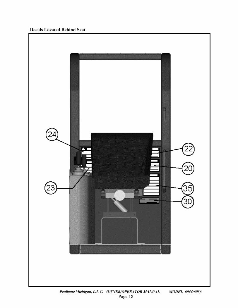
Decals Located Behind Seat
Page 19Pettibone Michigan, L.L.C. OWNER/OPERATOR MANUAL MODEL 6044/6036
Page 20
TRAVERSE LIFT
Pettibone Michigan, L.L.C. OWNER/OPERATOR MANUAL MODEL 6044/6036
Page 21Pettibone Michigan, L.L.C. OWNER/OPERATOR MANUAL MODEL 6044/6036
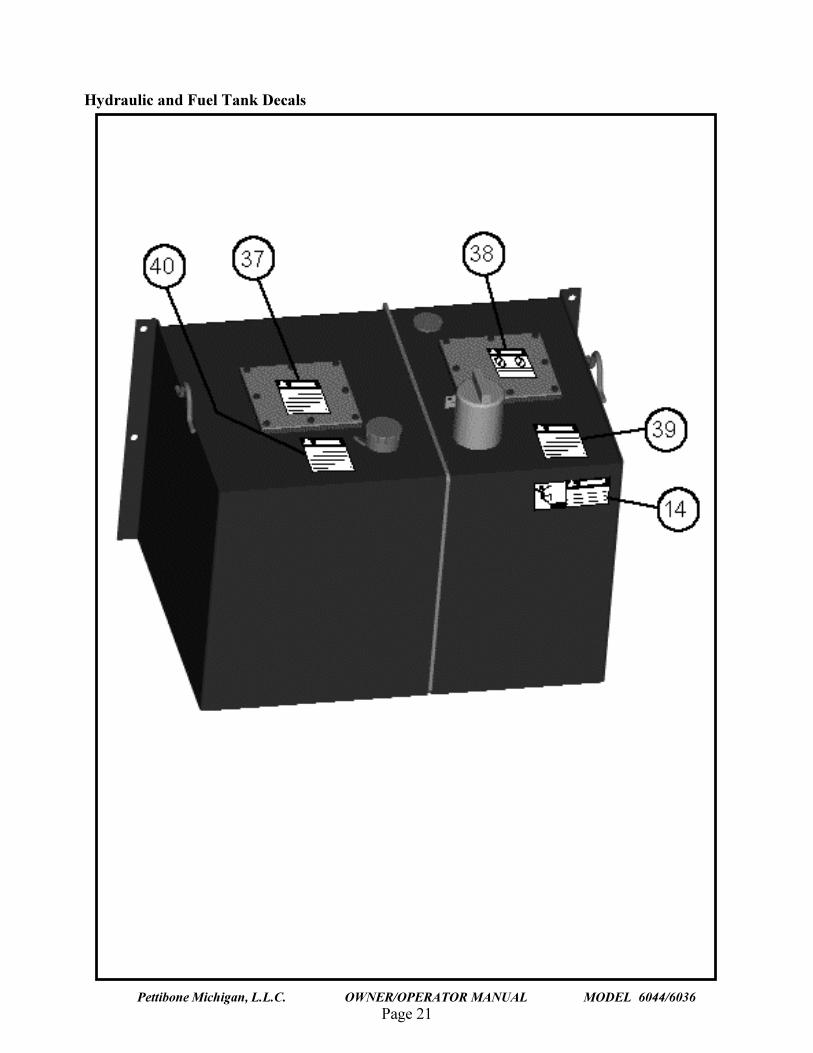
Hydraulic and Fuel Tank Decals
Page 22
TRAVERSE LIFT
Pettibone Michigan, L.L.C. OWNER/OPERATOR MANUAL MODEL 6044/6036
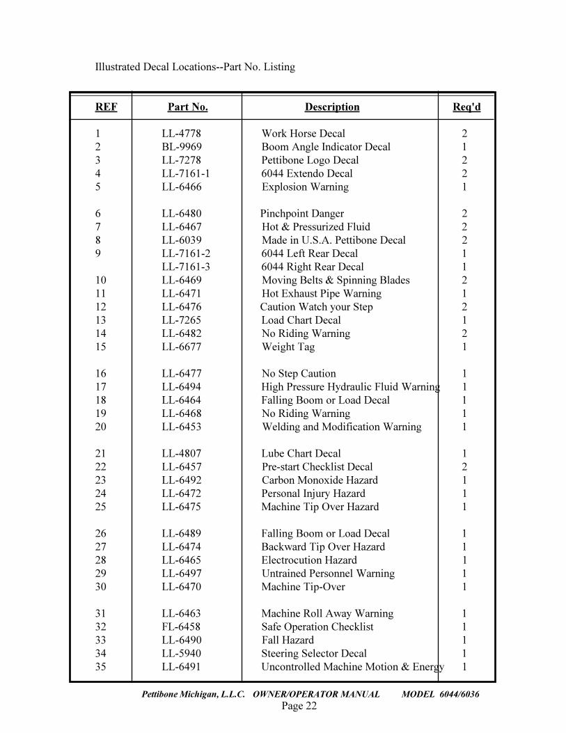
Illustrated Decal Locations--Part No. Listing
REF Part No. Description Req'd
1 LL-4778 Work Horse Decal 22 BL-9969 Boom Angle Indicator Decal 13 LL-7278 Pettibone Logo Decal 24 LL-7161-1 6044 Extendo Decal 25 LL-6466 Explosion Warning 1
6 LL-6480 Pinchpoint Danger 27 LL-6467 Hot & Pressurized Fluid 28 LL-6039 Made in U.S.A. Pettibone Decal 29 LL-7161-2 6044 Left Rear Decal 1
LL-7161-3 6044 Right Rear Decal 110 LL-6469 Moving Belts & Spinning Blades 211 LL-6471 Hot Exhaust Pipe Warning 112 LL-6476 Caution Watch your Step 213 LL-7265 Load Chart Decal 114 LL-6482 No Riding Warning 215 LL-6677 Weight Tag 1
16 LL-6477 No Step Caution 117 LL-6494 High Pressure Hydraulic Fluid Warning 118 LL-6464 Falling Boom or Load Decal 119 LL-6468 No Riding Warning 120 LL-6453 Welding and Modification Warning 1
21 LL-4807 Lube Chart Decal 122 LL-6457 Pre-start Checklist Decal 223 LL-6492 Carbon Monoxide Hazard 124 LL-6472 Personal Injury Hazard 125 LL-6475 Machine Tip Over Hazard 1
26 LL-6489 Falling Boom or Load Decal 127 LL-6474 Backward Tip Over Hazard 128 LL-6465 Electrocution Hazard 129 LL-6497 Untrained Personnel Warning 130 LL-6470 Machine Tip-Over 1
31 LL-6463 Machine Roll Away Warning 132 FL-6458 Safe Operation Checklist 133 LL-6490 Fall Hazard 134 LL-5940 Steering Selector Decal 135 LL-6491 Uncontrolled Machine Motion & Energy 1
Page 23Pettibone Michigan, L.L.C. OWNER/OPERATOR MANUAL MODEL 6044/6036
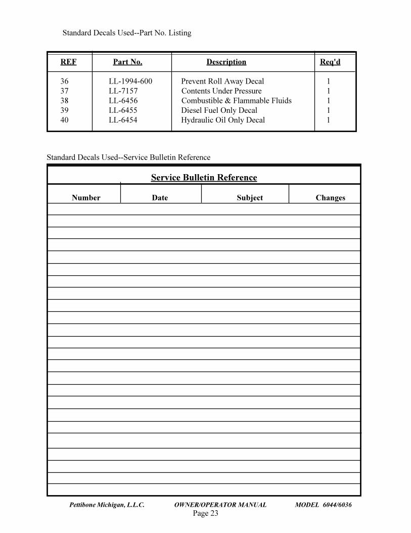
Standard Decals Used--Service Bulletin Reference
Service Bulletin Reference
Number Date Subject Changes
Standard Decals Used--Part No. Listing
REF Part No. Description Req'd
36 LL-1994-600 Prevent Roll Away Decal 137 LL-7157 Contents Under Pressure 138 LL-6456 Combustible & Flammable Fluids 139 LL-6455 Diesel Fuel Only Decal 140 LL-6454 Hydraulic Oil Only Decal 1
Page 24
TRAVERSE LIFT
Pettibone Michigan, L.L.C. OWNER/OPERATOR MANUAL MODEL 6044/6036
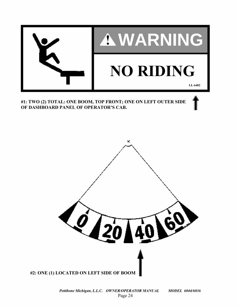
#2: ONE (1) LOCATED ON LEFT SIDE OF BOOM
#1: TWO (2) TOTAL: ONE BOOM, TOP FRONT; ONE ON LEFT OUTER SIDEOF DASHBOARD PANEL OF OPERATOR�S CAB.
LL-6482
! WARNING
NO RIDING
Page 25Pettibone Michigan, L.L.C. OWNER/OPERATOR MANUAL MODEL 6044/6036
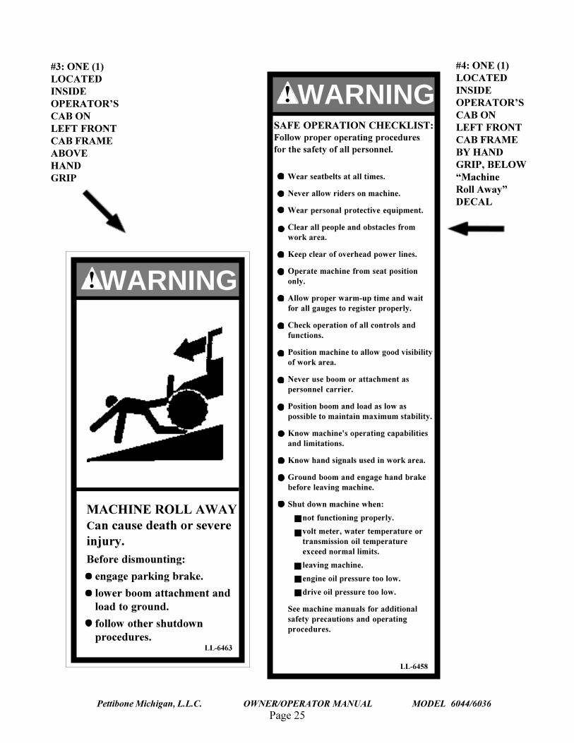
#4: ONE (1)LOCATEDINSIDEOPERATOR�SCAB ONLEFT FRONTCAB FRAMEBY HANDGRIP, BELOW�MachineRoll Away�DECAL
#3: ONE (1)LOCATEDINSIDEOPERATOR�SCAB ONLEFT FRONTCAB FRAMEABOVEHANDGRIP
WARNING
MACHINE ROLL AWAYCan cause death or severeinjury.Before dismounting:
engage parking brake.
lower boom attachment andload to ground.
follow other shutdownprocedures.
LL-6463
!
LL-6458
WARNING!SAFE OPERATION CHECKLIST:Follow proper operating proceduresfor the safety of all personnel.
Wear seatbelts at all times.
Never allow riders on machine.
Wear personal protective equipment.
Clear all people and obstacles fromwork area.
Keep clear of overhead power lines.
Operate machine from seat positiononly.
Allow proper warm-up time and waitfor all gauges to register properly.
Check operation of all controls andfunctions.
Position machine to allow good visibilityof work area.
Never use boom or attachment aspersonnel carrier.
Position boom and load as low aspossible to maintain maximum stability.
Know machine's operating capabilitiesand limitations.
Know hand signals used in work area.
Ground boom and engage hand brakebefore leaving machine.
Shut down machine when:
not functioning properly.
volt meter, water temperature ortransmission oil temperatureexceed normal limits.
leaving machine.
engine oil pressure too low.
drive oil pressure too low.
See machine manuals for additionalsafety precautions and operatingprocedures.
Page 26
TR
AV
ER
SE
LIF
T
Pettibone M
ichigan, L.L
.C.
OW
NE
R/O
PE
RA
TO
R M
AN
UA
L M
OD
EL
6044/6036
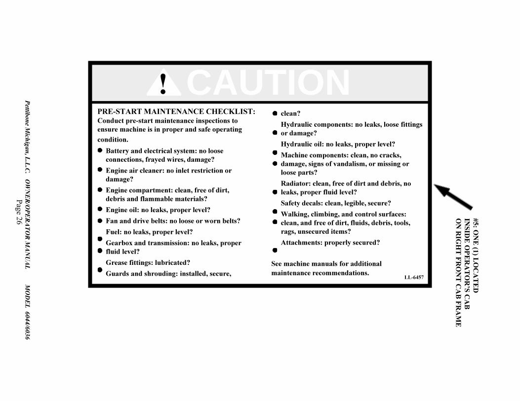
#5: ON
E (1) L
OC
AT
ED
INSID
E O
PE
RA
TO
R�S C
AB
ON
RIG
HT
FR
ON
T C
AB
FR
AM
E
CAUTION!PRE-START MAINTENANCE CHECKLIST:Conduct pre-start maintenance inspections toensure machine is in proper and safe operatingcondition.
LL-6457
Battery and electrical system: no looseconnections, frayed wires, damage?
Engine air cleaner: no inlet restriction ordamage?
Engine compartment: clean, free of dirt,debris and flammable materials?
Engine oil: no leaks, proper level?
Fan and drive belts: no loose or worn belts?
Fuel: no leaks, proper level?
Gearbox and transmission: no leaks, properfluid level?
Grease fittings: lubricated?
Guards and shrouding: installed, secure,
clean?
Hydraulic components: no leaks, loose fittingsor damage?
Hydraulic oil: no leaks, proper level?
Machine components: clean, no cracks,damage, signs of vandalism, or missing orloose parts?
Radiator: clean, free of dirt and debris, noleaks, proper fluid level?
Safety decals: clean, legible, secure?
Walking, climbing, and control surfaces:clean, and free of dirt, fluids, debris, tools,rags, unsecured items?
Attachments: properly secured?
See machine manuals for additionalmaintenance recommendations.
Page 27Pettibone Michigan, L.L.C. OWNER/OPERATOR MANUAL MODEL 6044/6036
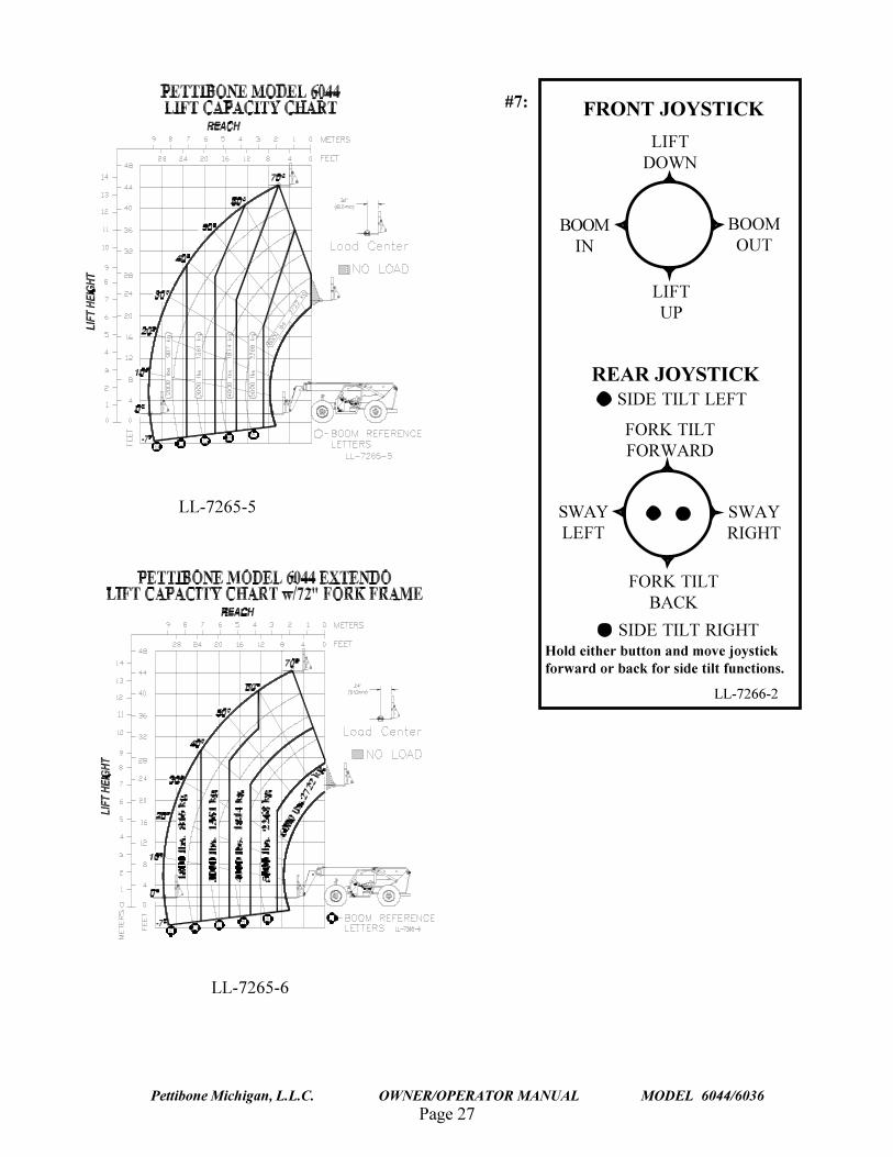
#6: #7:
LL-7265-6
LL-7265-5
REAR JOYSTICK
FRONT JOYSTICK
LIFTUP
BOOMOUT
BOOMIN
LIFTDOWN
SIDE TILT RIGHT
SIDE TILT LEFT
FORK TILTBACK
SWAYRIGHT
SWAYLEFT
FORK TILTFORWARD
Hold either button and move joystickforward or back for side tilt functions.
LL-7266-2
Page 28
TRAVERSE LIFT
Pettibone Michigan, L.L.C. OWNER/OPERATOR MANUAL MODEL 6044/6036
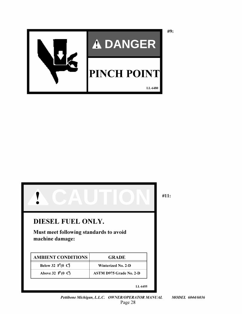
#9:
#11:
LL-6480
PINCH POINT
! DANGER
DIESEL FUEL ONLY.
Must meet following standards to avoidmachine damage:
AMBIENT CONDITIONS GRADE
Below 32 F (0 C) Winterized No. 2-D
Above 32 F (0 C) ASTM D975 Grade No. 2-D
LL-6455
CAUTION!
oo
o o
Page 29Pettibone Michigan, L.L.C. OWNER/OPERATOR MANUAL MODEL 6044/6036
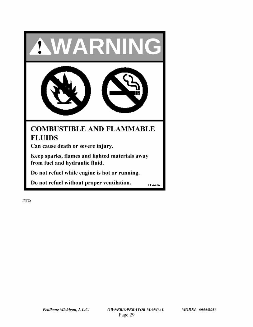
#12:
COMBUSTIBLE AND FLAMMABLEFLUIDSCan cause death or severe injury.
Keep sparks, flames and lighted materials awayfrom fuel and hydraulic fluid.
Do not refuel while engine is hot or running.
Do not refuel without proper ventilation.
WARNING!
LL-6456
Page 30
TRAVERSE LIFT
Pettibone Michigan, L.L.C. OWNER/OPERATOR MANUAL MODEL 6044/6036
#13:
Page 31Pettibone Michigan, L.L.C. OWNER/OPERATOR MANUAL MODEL 6044/6036
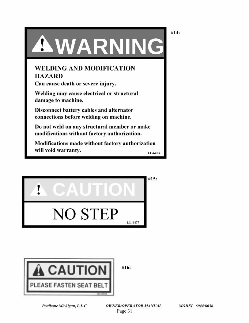
#14:
#16:
#15:
WELDING AND MODIFICATIONHAZARDCan cause death or severe injury.
Welding may cause electrical or structuraldamage to machine.
Disconnect battery cables and alternatorconnections before welding on machine.
Do not weld on any structural member or makemodifications without factory authorization.
Modifications made without factory authorizationwill void warranty.
LL-6453
! WARNING
! CAUTIONNO STEP
LL-6477
Page 32
TRAVERSE LIFT
Pettibone Michigan, L.L.C. OWNER/OPERATOR MANUAL MODEL 6044/6036
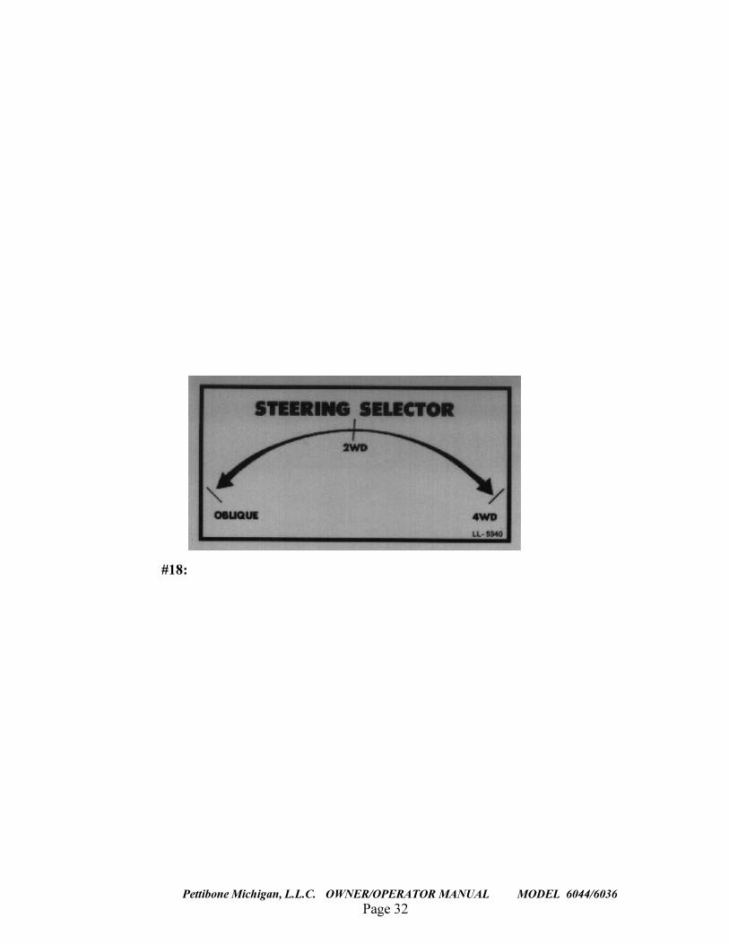
#18:
Page 33Pettibone Michigan, L.L.C. OWNER/OPERATOR MANUAL MODEL 6044/6036
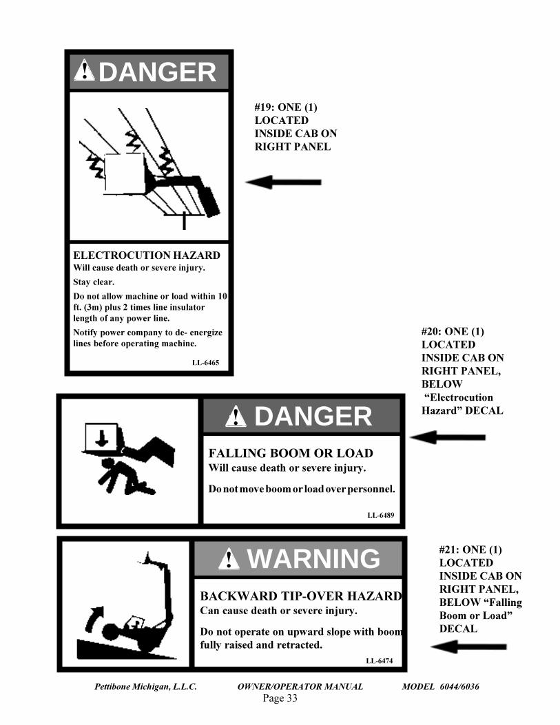
#21: ONE (1)LOCATEDINSIDE CAB ONRIGHT PANEL,BELOW �FallingBoom or Load�DECAL
#20: ONE (1)LOCATEDINSIDE CAB ONRIGHT PANEL,BELOW �ElectrocutionHazard� DECAL
#19: ONE (1)LOCATEDINSIDE CAB ONRIGHT PANEL
DANGER
LL-6465
ELECTROCUTION HAZARDWill cause death or severe injury.
Stay clear.
Do not allow machine or load within 10ft. (3m) plus 2 times line insulatorlength of any power line.
Notify power company to de- energizelines before operating machine.
!
LL-6489
FALLING BOOM OR LOADWill cause death or severe injury.
Do not move boom or load over personnel.
DANGER!
! WARNINGBACKWARD TIP-OVER HAZARDCan cause death or severe injury.
Do not operate on upward slope with boomfully raised and retracted.
LL-6474
Page 34
TRAVERSE LIFT
Pettibone Michigan, L.L.C. OWNER/OPERATOR MANUAL MODEL 6044/6036
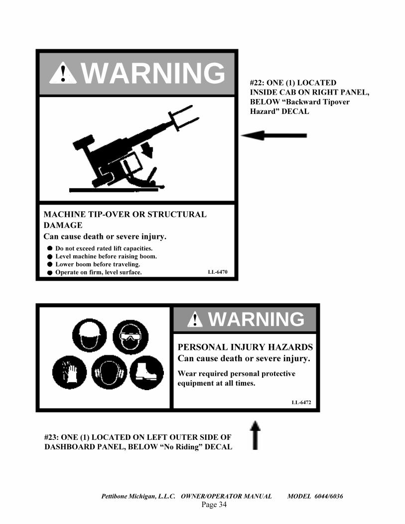
#23: ONE (1) LOCATED ON LEFT OUTER SIDE OFDASHBOARD PANEL, BELOW �No Riding� DECAL
#22: ONE (1) LOCATEDINSIDE CAB ON RIGHT PANEL,BELOW �Backward TipoverHazard� DECAL
! WARNING
MACHINE TIP-OVER OR STRUCTURALDAMAGECan cause death or severe injury.
Do not exceed rated lift capacities.Level machine before raising boom.Lower boom before traveling.Operate on firm, level surface. LL-6470
LL-6472
! WARNINGPERSONAL INJURY HAZARDSCan cause death or severe injury.
Wear required personal protectiveequipment at all times.
Page 35Pettibone Michigan, L.L.C. OWNER/OPERATOR MANUAL MODEL 6044/6036
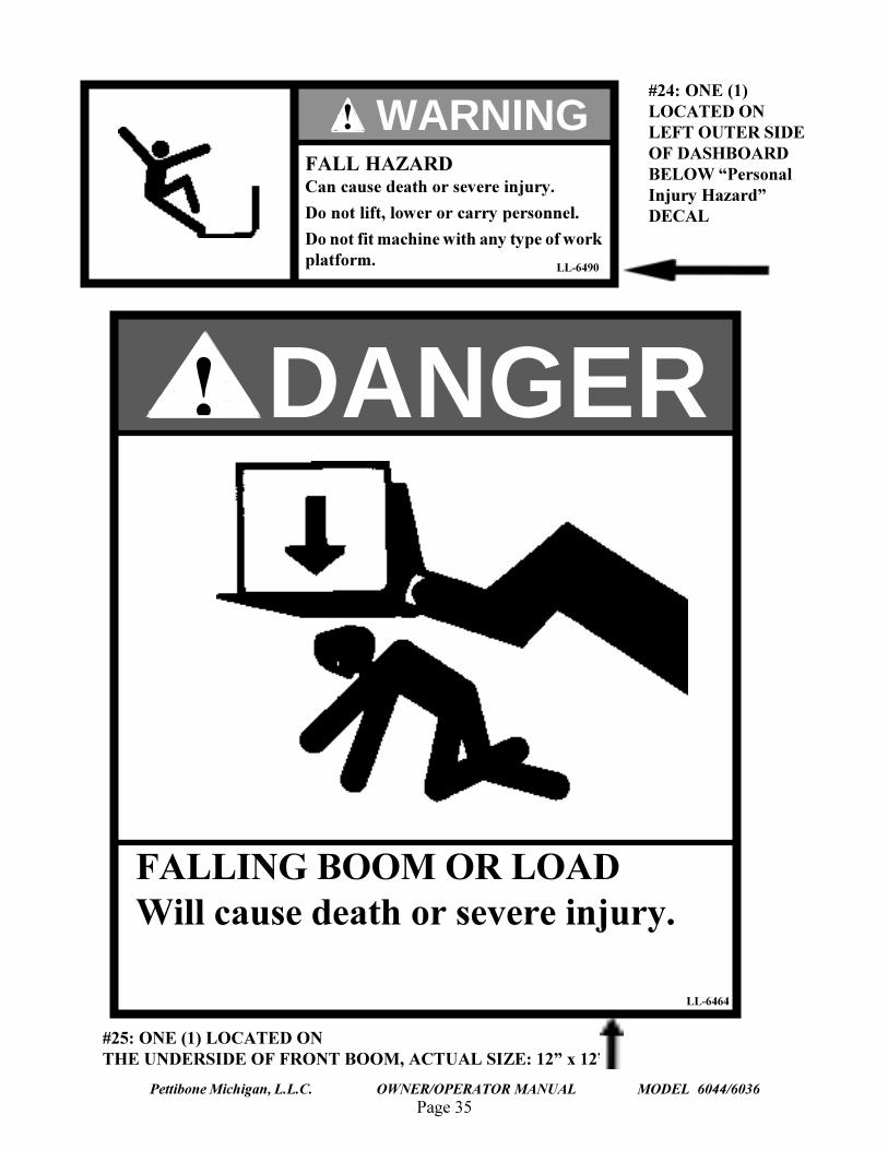
#24: ONE (1)LOCATED ONLEFT OUTER SIDEOF DASHBOARDBELOW �PersonalInjury Hazard�DECAL
#25: ONE (1) LOCATED ONTHE UNDERSIDE OF FRONT BOOM, ACTUAL SIZE: 12� x 12�
LL-6490
FALL HAZARDCan cause death or severe injury.
Do not lift, lower or carry personnel.
Do not fit machine with any type of workplatform.
! WARNING
FALLING BOOM OR LOADWill cause death or severe injury.
! DANGER
LL-6464
Page 36
TRAVERSE LIFT
Pettibone Michigan, L.L.C. OWNER/OPERATOR MANUAL MODEL 6044/6036
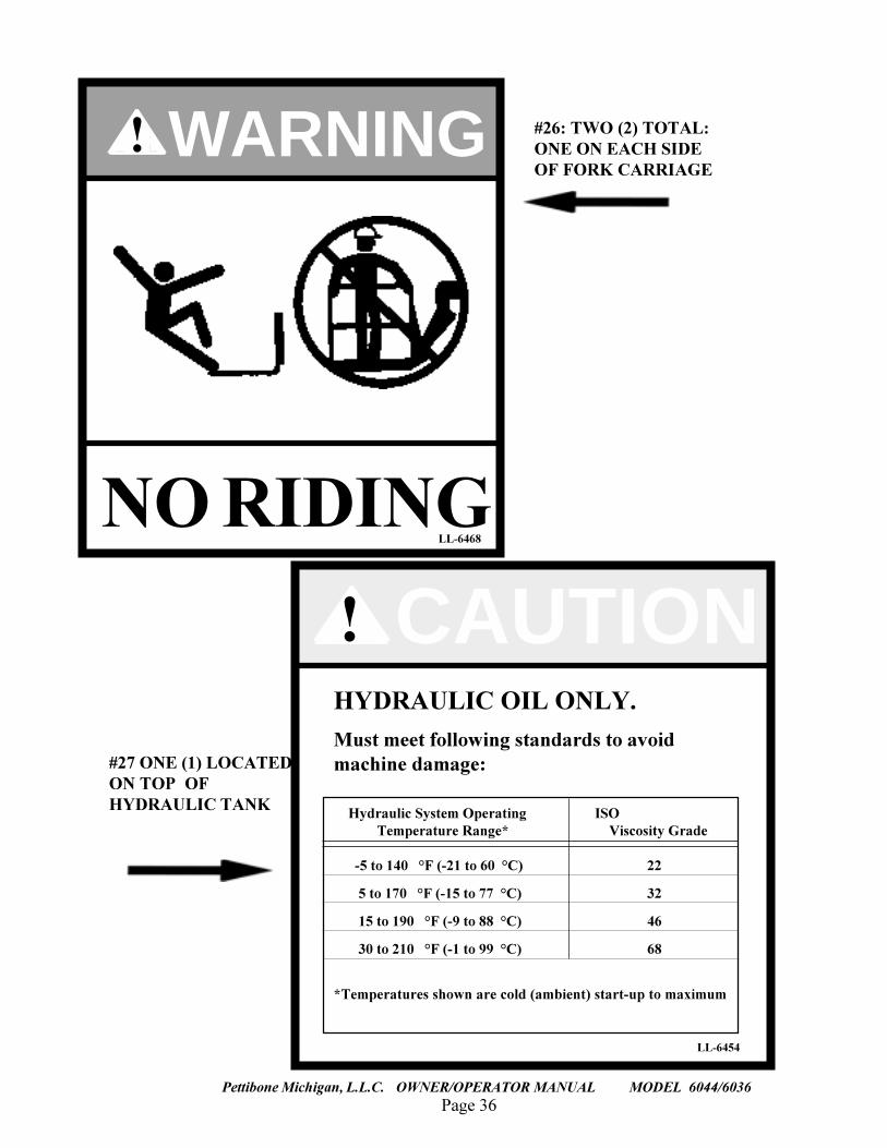
#26: TWO (2) TOTAL:ONE ON EACH SIDEOF FORK CARRIAGE
#27 ONE (1) LOCATEDON TOP OFHYDRAULIC TANK
HYDRAULIC OIL ONLY.
Must meet following standards to avoidmachine damage:
Hydraulic System Operating ISO Temperature Range* Viscosity Grade
-5 to 140 °F (-21 to 60 °C) 22
5 to 170 °F (-15 to 77 °C) 32
15 to 190 °F (-9 to 88 °C) 46
30 to 210 °F (-1 to 99 °C) 68
*Temperatures shown are cold (ambient) start-up to maximum
LL-6454
CAUTION!
NO RIDING
! WARNING
LL-6468
Page 37Pettibone Michigan, L.L.C. OWNER/OPERATOR MANUAL MODEL 6044/6036
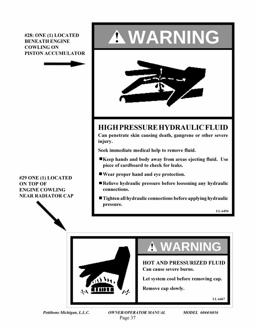
#28: ONE (1) LOCATEDBENEATH ENGINECOWLING ONPISTON ACCUMULATOR
#29 ONE (1) LOCATEDON TOP OFENGINE COWLINGNEAR RADIATOR CAP
LL-6494
HIGH PRESSURE HYDRAULIC FLUIDCan penetrate skin causing death, gangrene or other severeinjury.
Seek immediate medical help to remove fluid.
Keep hands and body away from areas ejecting fluid. Usepiece of cardboard to check for leaks.
Wear proper hand and eye protection.
Relieve hydraulic pressure before loosening any hydraulicconnections.
Tighten all hydraulic connections before applying hydraulicpressure.
! WARNING
! WARNINGHOT AND PRESSURIZED FLUIDCan cause severe burns.
Let system cool before removing cap.
Remove cap slowly.
LL-6467
Page 38
TRAVERSE LIFT
Pettibone Michigan, L.L.C. OWNER/OPERATOR MANUAL MODEL 6044/6036
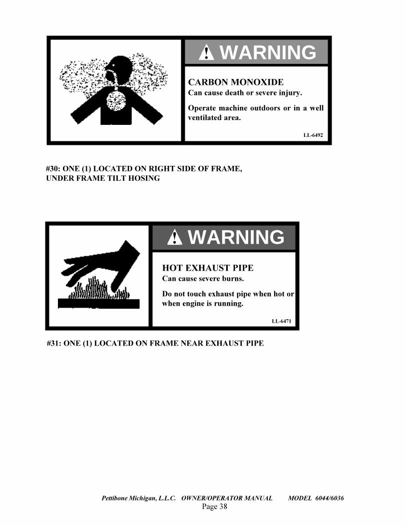
#30: ONE (1) LOCATED ON RIGHT SIDE OF FRAME,UNDER FRAME TILT HOSING
#31: ONE (1) LOCATED ON FRAME NEAR EXHAUST PIPE
LL-6471
! WARNINGHOT EXHAUST PIPECan cause severe burns.
Do not touch exhaust pipe when hot orwhen engine is running.
LL-6492
CARBON MONOXIDECan cause death or severe injury.
Operate machine outdoors or in a wellventilated area.
! WARNING
Page 39Pettibone Michigan, L.L.C. OWNER/OPERATOR MANUAL MODEL 6044/6036
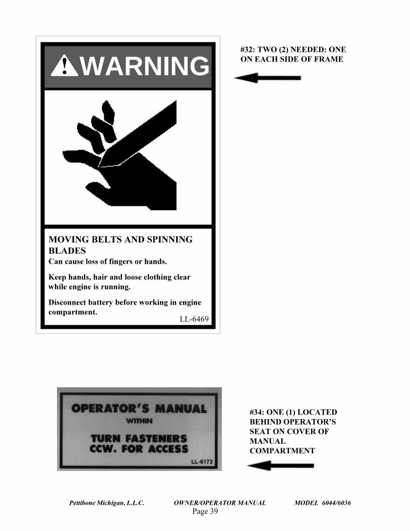
#32: TWO (2) NEEDED: ONEON EACH SIDE OF FRAME
#34: ONE (1) LOCATEDBEHIND OPERATOR�SSEAT ON COVER OFMANUALCOMPARTMENT
MOVING BELTS AND SPINNINGBLADESCan cause loss of fingers or hands.
Keep hands, hair and loose clothing clearwhile engine is running.
Disconnect battery before working in enginecompartment.
! WARNING
LL-6469
Page 40
TRAVERSE LIFT
Pettibone Michigan, L.L.C. OWNER/OPERATOR MANUAL MODEL 6044/6036
MATERIAL SAFETY DATA SHEETS (MSDS)
The Federal Occupational, Safety and Health Administration (OSHA) Standard 29 CFR 1910.1200 andin some cases, state and local Right-To-Know laws, may require that specific Material Safety DataSheets be available to employees prior to operating this equipment. These sheets include information onsubstances contained in the equipment such as antifreeze, battery acid, diesel fuel, engine oil, grease andhydraulic oil.
Upon written request, Pettibone Michigan, L.L.C. will provide the Material Safety Data Sheetsapplicable to our product line, at no extra cost. Write to:
Pettibone Michigan L.L.C.P.O. Box 368
Baraga, MI 49908
Ph. 906-353-6611Fax 906-353-6325
The customer�s return address, machine model and serial number must be included to ensure a promptresponse.
IDENTIFICATION NUMBERS
Write the machine�s model number, Product Identification Number and serial numbers on the linesprovided below. If necessary, give these numbers to the dealer when parts or information are needed for

Page 41Pettibone Michigan, L.L.C. OWNER/OPERATOR MANUAL MODEL 6044/6036
THIS PAGEINTENTIONALLY
LEFT BLANK
Page 42
TRAVERSE LIFT
Pettibone Michigan, L.L.C. OWNER/OPERATOR MANUAL MODEL 6044/6036
the machine.
Make a record of the numbers. Keep the record in a safe place. If the machine is stolen, report thenumbers to the local law enforcement agency.
MACHINE MODEL NUMBER _________________________________________
PRODUCT IDENTIFICATION NUMBER _________________________________________
ENGINE SERIAL NUMBER_________________________________________
ROPS SERIAL NUMBER _________________________________________
SAFETY
MACHINE INSPECTION AND DELIVERY REPORT
The Machine Inspection and Delivery report is shipped loose in the back of this manual. Makesure your dealer performs a checkup within the first 150 hours of operation or 30 days after delivery,whichever comes first.
NOTEThe customer�s cost for this inspection will be for filters, oil or other accessories.If the dealer comes to the machine, there may also be a cost for the time andtravel.
EQUIPMENT
Page 43Pettibone Michigan, L.L.C. OWNER/OPERATOR MANUAL MODEL 6044/6036
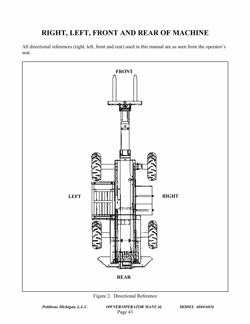
RIGHT, LEFT, FRONT AND REAR OF MACHINE
All directional references (right, left, front and rear) used in this manual are as seen from the operator�sseat.
FRONT
REAR
LEFT RIGHT
Figure 2. Directional Reference
Page 44
TRAVERSE LIFT
Pettibone Michigan, L.L.C. OWNER/OPERATOR MANUAL MODEL 6044/6036
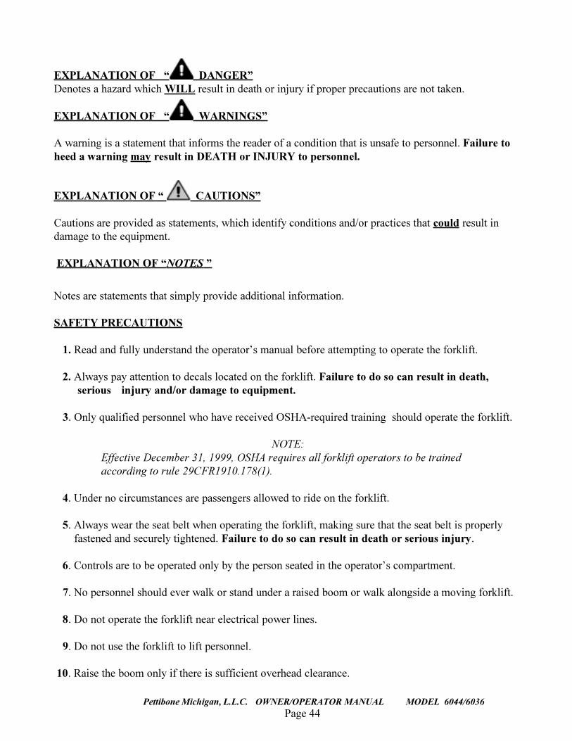
EXPLANATION OF � DANGER�Denotes a hazard which WILL result in death or injury if proper precautions are not taken.
EXPLANATION OF � WARNINGS�
A warning is a statement that informs the reader of a condition that is unsafe to personnel. Failure toheed a warning may result in DEATH or INJURY to personnel.
EXPLANATION OF � CAUTIONS�
Cautions are provided as statements, which identify conditions and/or practices that could result indamage to the equipment.
EXPLANATION OF �NOTES �
Notes are statements that simply provide additional information.
SAFETY PRECAUTIONS
1. Read and fully understand the operator�s manual before attempting to operate the forklift.
2. Always pay attention to decals located on the forklift. Failure to do so can result in death,serious injury and/or damage to equipment.
3. Only qualified personnel who have received OSHA-required training should operate the forklift.
NOTE:Effective December 31, 1999, OSHA requires all forklift operators to be trainedaccording to rule 29CFR1910.178(1).
4. Under no circumstances are passengers allowed to ride on the forklift.
5. Always wear the seat belt when operating the forklift, making sure that the seat belt is properlyfastened and securely tightened. Failure to do so can result in death or serious injury.
6. Controls are to be operated only by the person seated in the operator�s compartment.
7. No personnel should ever walk or stand under a raised boom or walk alongside a moving forklift.
8. Do not operate the forklift near electrical power lines.
9. Do not use the forklift to lift personnel.
10. Raise the boom only if there is sufficient overhead clearance.
Page 45Pettibone Michigan, L.L.C. OWNER/OPERATOR MANUAL MODEL 6044/6036
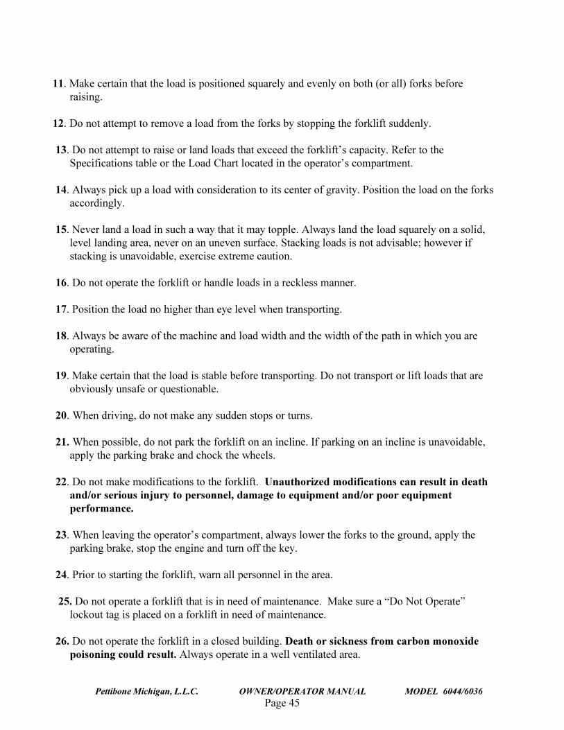
11. Make certain that the load is positioned squarely and evenly on both (or all) forks beforeraising.
12. Do not attempt to remove a load from the forks by stopping the forklift suddenly.
13. Do not attempt to raise or land loads that exceed the forklift�s capacity. Refer to theSpecifications table or the Load Chart located in the operator�s compartment.
14. Always pick up a load with consideration to its center of gravity. Position the load on the forksaccordingly.
15. Never land a load in such a way that it may topple. Always land the load squarely on a solid,level landing area, never on an uneven surface. Stacking loads is not advisable; however ifstacking is unavoidable, exercise extreme caution.
16. Do not operate the forklift or handle loads in a reckless manner.
17. Position the load no higher than eye level when transporting.
18. Always be aware of the machine and load width and the width of the path in which you areoperating.
19. Make certain that the load is stable before transporting. Do not transport or lift loads that areobviously unsafe or questionable.
20. When driving, do not make any sudden stops or turns.
21. When possible, do not park the forklift on an incline. If parking on an incline is unavoidable,apply the parking brake and chock the wheels.
22. Do not make modifications to the forklift. Unauthorized modifications can result in deathand/or serious injury to personnel, damage to equipment and/or poor equipmentperformance.
23. When leaving the operator�s compartment, always lower the forks to the ground, apply theparking brake, stop the engine and turn off the key.
24. Prior to starting the forklift, warn all personnel in the area.
25. Do not operate a forklift that is in need of maintenance. Make sure a �Do Not Operate�lockout tag is placed on a forklift in need of maintenance.
26. Do not operate the forklift in a closed building. Death or sickness from carbon monoxidepoisoning could result. Always operate in a well ventilated area.
Page 46
TRAVERSE LIFT
Pettibone Michigan, L.L.C. OWNER/OPERATOR MANUAL MODEL 6044/6036
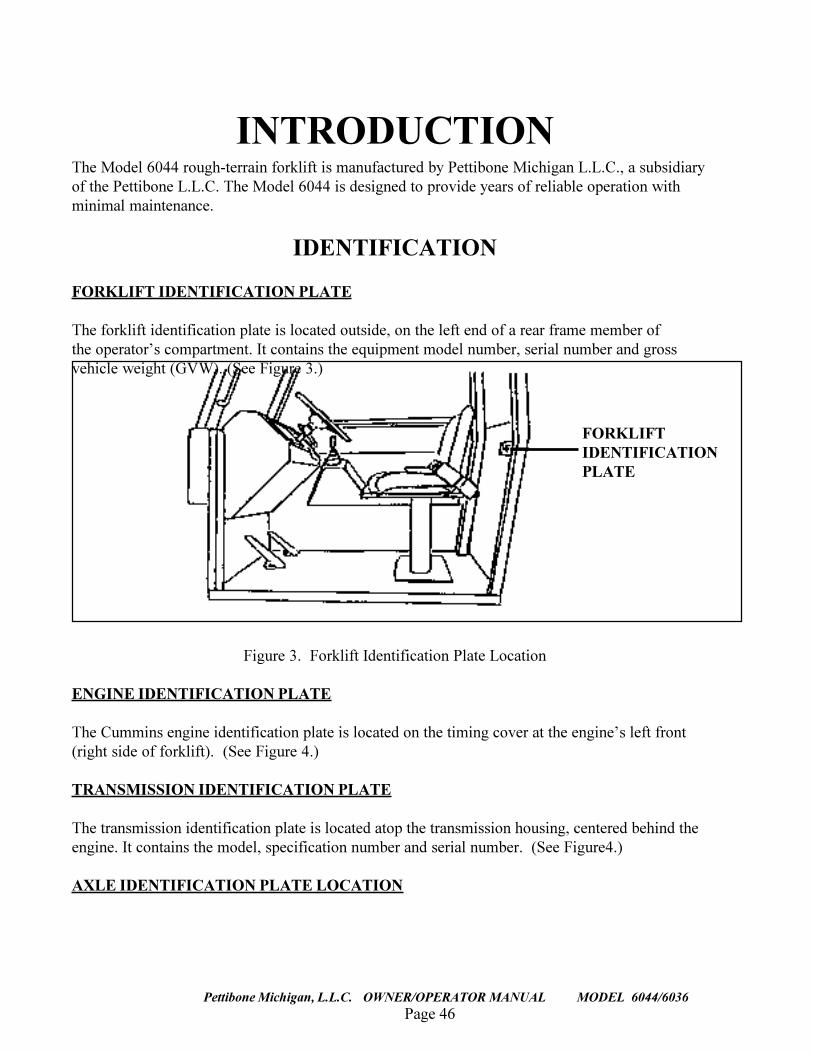
INTRODUCTIONThe Model 6044 rough-terrain forklift is manufactured by Pettibone Michigan L.L.C., a subsidiaryof the Pettibone L.L.C. The Model 6044 is designed to provide years of reliable operation withminimal maintenance.
IDENTIFICATION
FORKLIFT IDENTIFICATION PLATE
The forklift identification plate is located outside, on the left end of a rear frame member ofthe operator�s compartment. It contains the equipment model number, serial number and grossvehicle weight (GVW). (See Figure 3.)
Figure 3. Forklift Identification Plate Location
ENGINE IDENTIFICATION PLATE
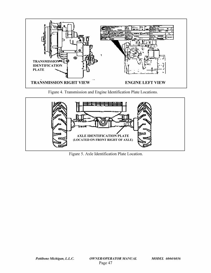
The Cummins engine identification plate is located on the timing cover at the engine�s left front(right side of forklift). (See Figure 4.)
TRANSMISSION IDENTIFICATION PLATE
The transmission identification plate is located atop the transmission housing, centered behind theengine. It contains the model, specification number and serial number. (See Figure4.)
AXLE IDENTIFICATION PLATE LOCATION
FORKLIFTIDENTIFICATIONPLATE
Page 47Pettibone Michigan, L.L.C. OWNER/OPERATOR MANUAL MODEL 6044/6036
TRANSMISSIONIDENTIFICATIONPLATE
ENGINEIDENTIFICATIONPLATE
TRANSMISSION RIGHT VIEW
Figure 4. Transmission and Engine Identification Plate Locations.
ENGINE LEFT VIEW
AXLE IDENTIFICATION PLATE(LOCATED ON FRONT RIGHT OF AXLE)
Figure 5. Axle Identification Plate Location.
Page 48
TRAVERSE LIFT
Pettibone Michigan, L.L.C. OWNER/OPERATOR MANUAL MODEL 6044/6036
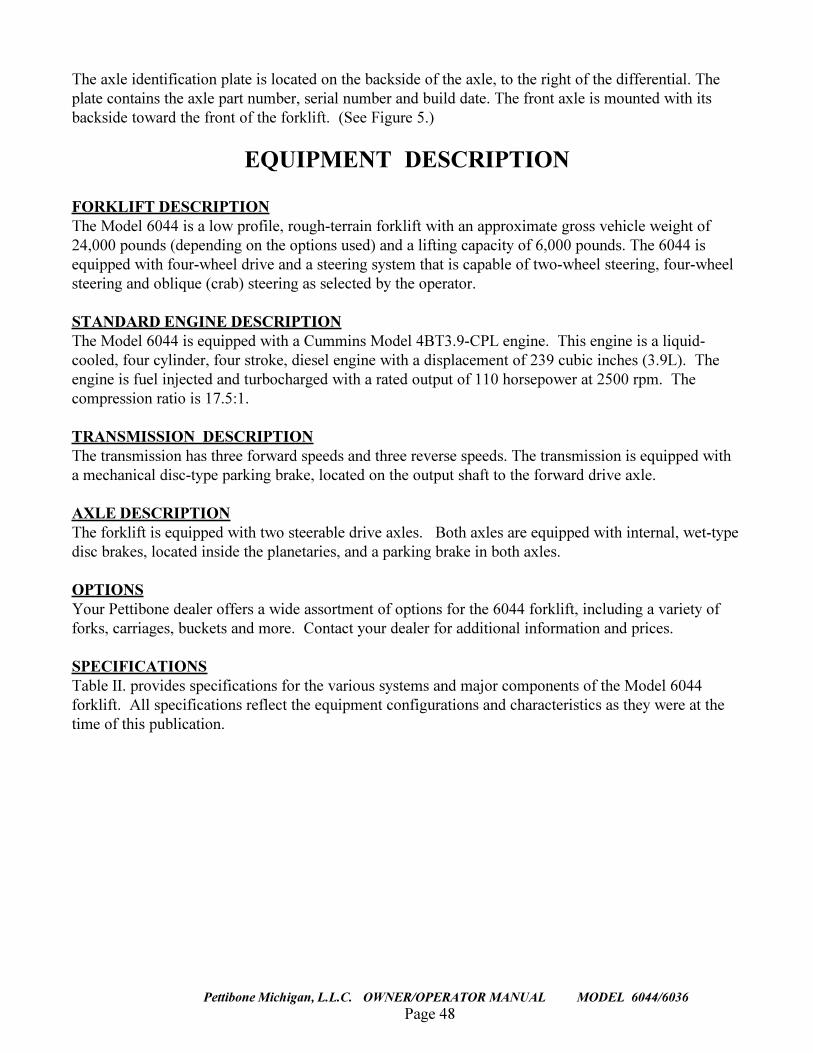
The axle identification plate is located on the backside of the axle, to the right of the differential. Theplate contains the axle part number, serial number and build date. The front axle is mounted with itsbackside toward the front of the forklift. (See Figure 5.)
EQUIPMENT DESCRIPTION
FORKLIFT DESCRIPTIONThe Model 6044 is a low profile, rough-terrain forklift with an approximate gross vehicle weight of24,000 pounds (depending on the options used) and a lifting capacity of 6,000 pounds. The 6044 isequipped with four-wheel drive and a steering system that is capable of two-wheel steering, four-wheelsteering and oblique (crab) steering as selected by the operator.
STANDARD ENGINE DESCRIPTIONThe Model 6044 is equipped with a Cummins Model 4BT3.9-CPL engine. This engine is a liquid-cooled, four cylinder, four stroke, diesel engine with a displacement of 239 cubic inches (3.9L). Theengine is fuel injected and turbocharged with a rated output of 110 horsepower at 2500 rpm. Thecompression ratio is 17.5:1.
TRANSMISSION DESCRIPTIONThe transmission has three forward speeds and three reverse speeds. The transmission is equipped witha mechanical disc-type parking brake, located on the output shaft to the forward drive axle.
AXLE DESCRIPTIONThe forklift is equipped with two steerable drive axles. Both axles are equipped with internal, wet-typedisc brakes, located inside the planetaries, and a parking brake in both axles.
OPTIONSYour Pettibone dealer offers a wide assortment of options for the 6044 forklift, including a variety offorks, carriages, buckets and more. Contact your dealer for additional information and prices.
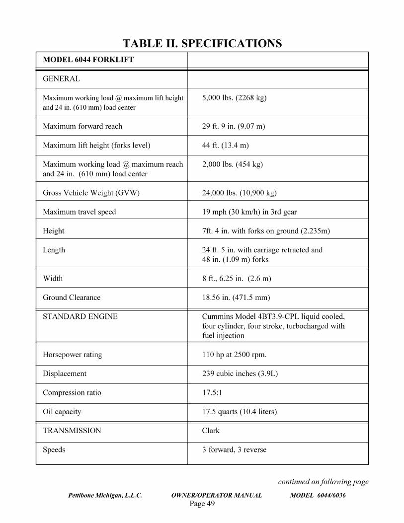
SPECIFICATIONSTable II. provides specifications for the various systems and major components of the Model 6044forklift. All specifications reflect the equipment configurations and characteristics as they were at thetime of this publication.
Page 49Pettibone Michigan, L.L.C. OWNER/OPERATOR MANUAL MODEL 6044/6036
TABLE II. SPECIFICATIONSMODEL 6044 FORKLIFT
GENERAL
Maximum working load @ maximum lift height 5,000 lbs. (2268 kg)and 24 in. (610 mm) load center
Maximum forward reach 29 ft. 9 in. (9.07 m)
Maximum lift height (forks level) 44 ft. (13.4 m)
Maximum working load @ maximum reach 2,000 lbs. (454 kg)and 24 in. (610 mm) load center
Gross Vehicle Weight (GVW) 24,000 lbs. (10,900 kg)
Maximum travel speed 19 mph (30 km/h) in 3rd gear
Height 7ft. 4 in. with forks on ground (2.235m)
Length 24 ft. 5 in. with carriage retracted and48 in. (1.09 m) forks
Width 8 ft., 6.25 in. (2.6 m)
Ground Clearance 18.56 in. (471.5 mm)
STANDARD ENGINE Cummins Model 4BT3.9-CPL liquid cooled,four cylinder, four stroke, turbocharged withfuel injection
Horsepower rating 110 hp at 2500 rpm.
Displacement 239 cubic inches (3.9L)
Compression ratio 17.5:1
Oil capacity 17.5 quarts (10.4 liters)
TRANSMISSION Clark
Speeds 3 forward, 3 reverse
continued on following page
Page 50
TRAVERSE LIFT
Pettibone Michigan, L.L.C. OWNER/OPERATOR MANUAL MODEL 6044/6036
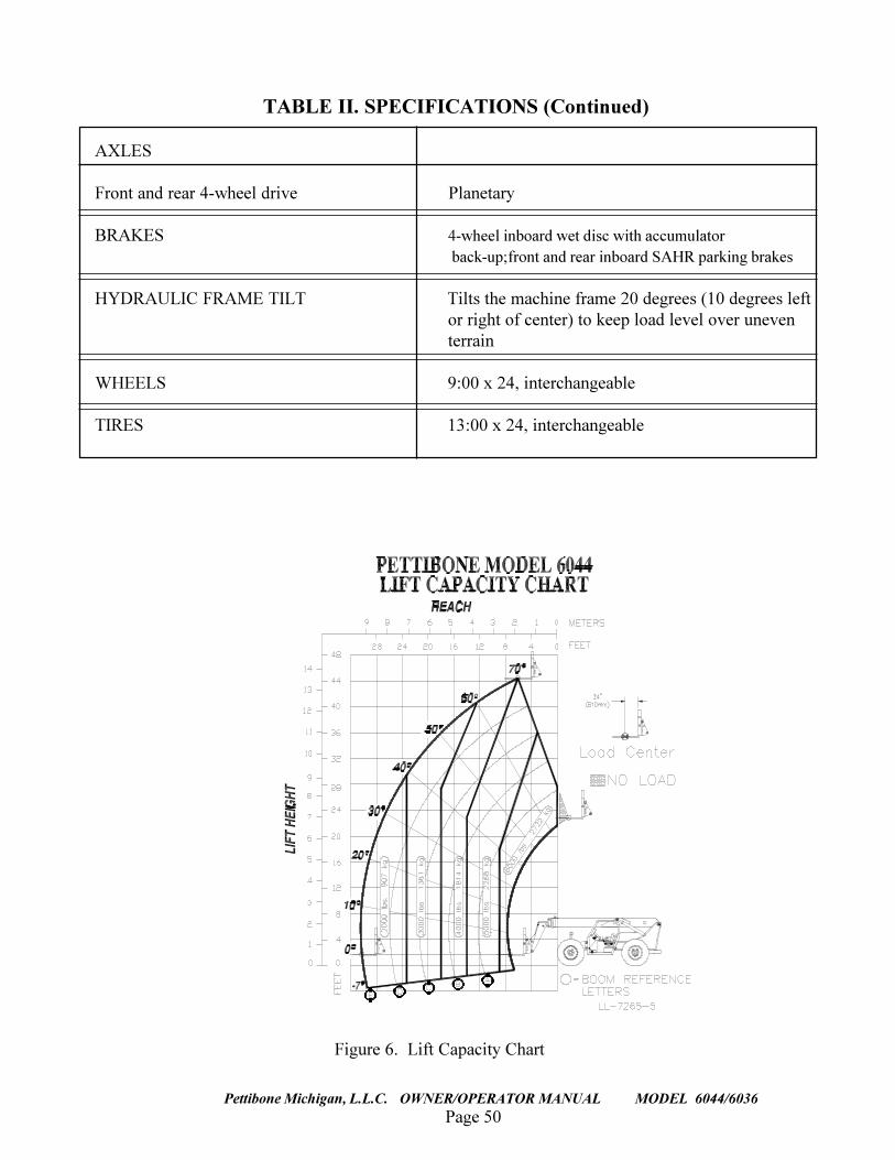
Figure 6. Lift Capacity Chart
TABLE II. SPECIFICATIONS (Continued)
AXLES
Front and rear 4-wheel drive Planetary
BRAKES 4-wheel inboard wet disc with accumulator back-up;front and rear inboard SAHR parking brakes
HYDRAULIC FRAME TILT Tilts the machine frame 20 degrees (10 degrees leftor right of center) to keep load level over uneventerrain
WHEELS 9:00 x 24, interchangeable
TIRES 13:00 x 24, interchangeable
Page 51Pettibone Michigan, L.L.C. OWNER/OPERATOR MANUAL MODEL 6044/6036
This section describes the location and func-tion of each gauge and control in theoperator�s compartment. With the engine�off�, practice reaching for these controls asyou read about them. This should help youbecome familiar with their location.
Entering the Operator�s Compartment
Proper care should be used whenever enteringor leaving the operator�s compartment. Usethe step and grab handle provided and alwayskeep them clear of debris.
NEVER USE THE STEERING WHEELOR ARM REST AS A GRAB HANDLE!
Use both hands when climbing onmachine. Failure to comply may result inpersonal injury.
Never jump down from theoperator�s compartment when leaving themachine.
Operator�s Seat
The operator�s seat can be adjusted to moveforward or back. The horizontal adjustmentlock lever is located under the front of theseat. (See Fig. 2-2)
Adjust the seat as follows:
1. Move lock lever to the left and hold.
2. Slide the seat forward or back to your desired position.
!
!
!
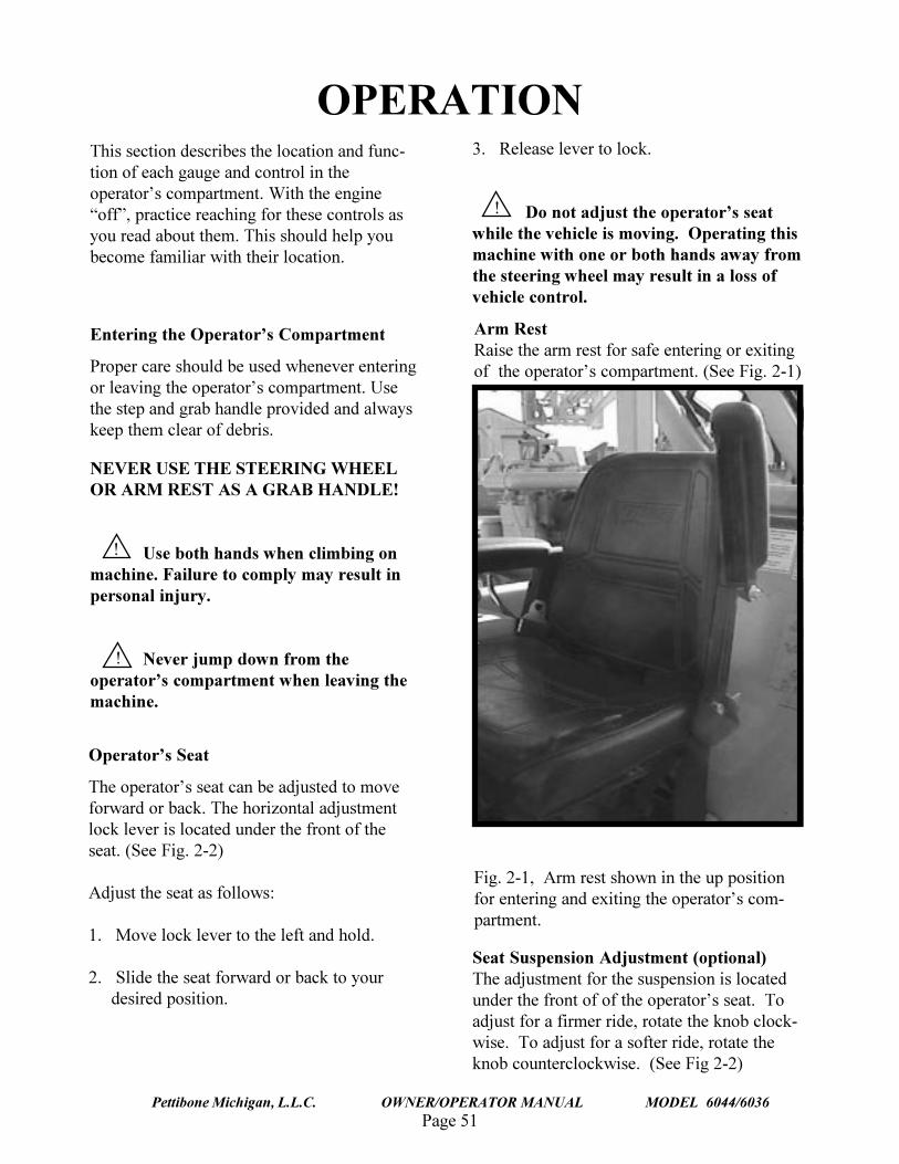
Fig. 2-1, Arm rest shown in the up positionfor entering and exiting the operator�s com-partment.
Arm RestRaise the arm rest for safe entering or exitingof the operator�s compartment. (See Fig. 2-1)
Seat Suspension Adjustment (optional)The adjustment for the suspension is locatedunder the front of of the operator�s seat. Toadjust for a firmer ride, rotate the knob clock-wise. To adjust for a softer ride, rotate theknob counterclockwise. (See Fig 2-2)
3. Release lever to lock.
Do not adjust the operator�s seatwhile the vehicle is moving. Operating thismachine with one or both hands away fromthe steering wheel may result in a loss ofvehicle control.
OPERATION
Page 52
TRAVERSE LIFT
Pettibone Michigan, L.L.C. OWNER/OPERATOR MANUAL MODEL 6044/6036
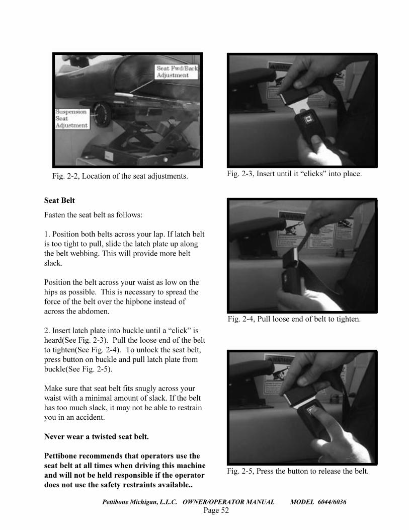
Fig. 2-2, Location of the seat adjustments.
Seat Belt
Fasten the seat belt as follows:
1. Position both belts across your lap. If latch beltis too tight to pull, slide the latch plate up alongthe belt webbing. This will provide more beltslack.
Position the belt across your waist as low on thehips as possible. This is necessary to spread theforce of the belt over the hipbone instead ofacross the abdomen.
2. Insert latch plate into buckle until a �click� isheard(See Fig. 2-3). Pull the loose end of the beltto tighten(See Fig. 2-4). To unlock the seat belt,press button on buckle and pull latch plate frombuckle(See Fig. 2-5).
Make sure that seat belt fits snugly across yourwaist with a minimal amount of slack. If the belthas too much slack, it may not be able to restrainyou in an accident.
Never wear a twisted seat belt.
Pettibone recommends that operators use theseat belt at all times when driving this machineand will not be held responsible if the operatordoes not use the safety restraints available..
Fig. 2-3, Insert until it �clicks� into place.
Fig. 2-4, Pull loose end of belt to tighten.
Fig. 2-5, Press the button to release the belt.
Page 53Pettibone Michigan, L.L.C. OWNER/OPERATOR MANUAL MODEL 6044/6036
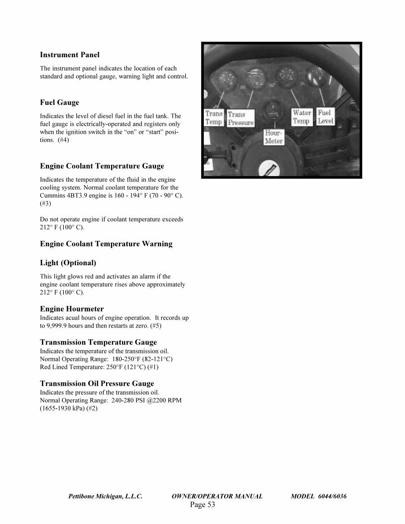
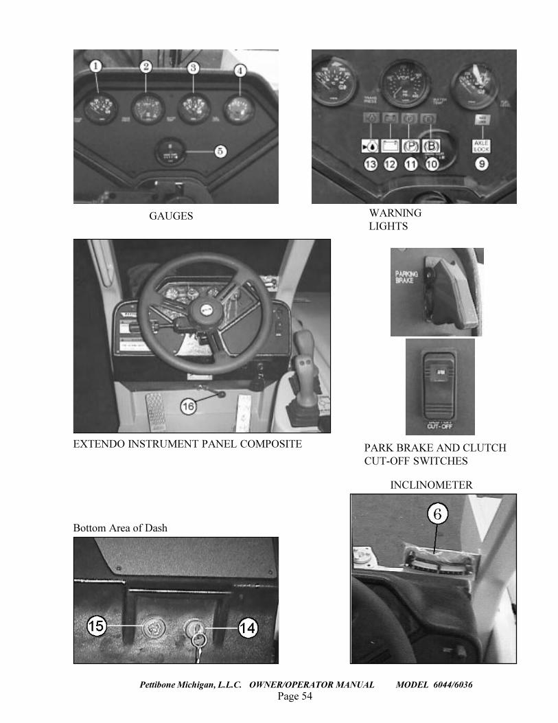
Instrument Panel
The instrument panel indicates the location of eachstandard and optional gauge, warning light and control.
Fuel Gauge
Indicates the level of diesel fuel in the fuel tank. Thefuel gauge is electrically-operated and registers onlywhen the ignition switch in the �on� or �start� posi-tions. (#4)
Engine Coolant Temperature Gauge
Indicates the temperature of the fluid in the enginecooling system. Normal coolant temperature for theCummins 4BT3.9 engine is 160 - 194° F (70 - 90° C).(#3)
Do not operate engine if coolant temperature exceeds212° F (100° C).
Engine Coolant Temperature Warning
Light (Optional)
This light glows red and activates an alarm if theengine coolant temperature rises above approximately212° F (100° C).
Engine HourmeterIndicates acual hours of engine operation. It records upto 9,999.9 hours and then restarts at zero. (#5)
Transmission Temperature GaugeIndicates the temperature of the transmission oil.Normal Operating Range: 180-250°F (82-121°C)Red Lined Temperature: 250°F (121°C) (#1)
Transmission Oil Pressure GaugeIndicates the pressure of the transmission oil.Normal Operating Range: 240-280 PSI @2200 RPM(1655-1930 kPa) (#2)
Page 54
TRAVERSE LIFT
Pettibone Michigan, L.L.C. OWNER/OPERATOR MANUAL MODEL 6044/6036
EXTENDO INSTRUMENT PANEL COMPOSITE
Bottom Area of Dash
GAUGES WARNINGLIGHTS
INCLINOMETER
PARK BRAKE AND CLUTCHCUT-OFF SWITCHES
Page 55Pettibone Michigan, L.L.C. OWNER/OPERATOR MANUAL MODEL 6044/6036
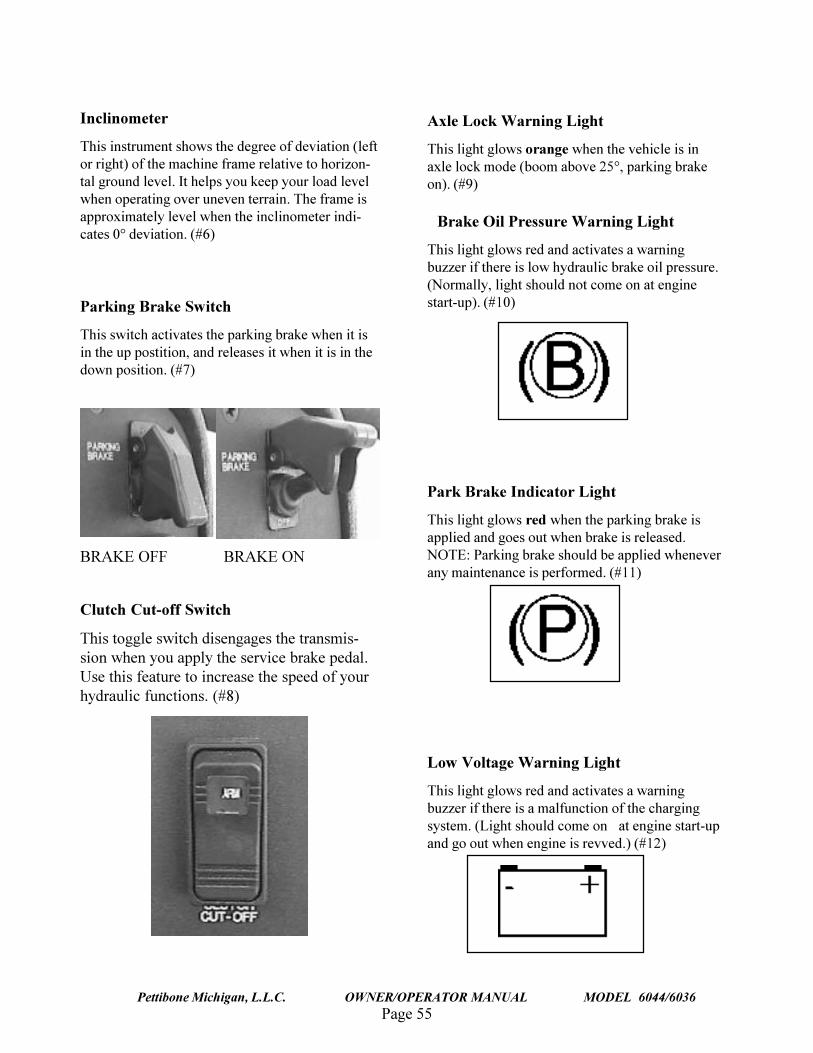
Inclinometer
This instrument shows the degree of deviation (leftor right) of the machine frame relative to horizon-tal ground level. It helps you keep your load levelwhen operating over uneven terrain. The frame isapproximately level when the inclinometer indi-cates 0° deviation. (#6)
Parking Brake Switch
This switch activates the parking brake when it isin the up postition, and releases it when it is in thedown position. (#7)
BRAKE OFF BRAKE ON
Clutch Cut-off Switch
This toggle switch disengages the transmis-sion when you apply the service brake pedal.Use this feature to increase the speed of yourhydraulic functions. (#8)
Axle Lock Warning Light
This light glows orange when the vehicle is inaxle lock mode (boom above 25°, parking brakeon). (#9)
Brake Oil Pressure Warning Light
This light glows red and activates a warningbuzzer if there is low hydraulic brake oil pressure.(Normally, light should not come on at enginestart-up). (#10)
Low Voltage Warning Light
This light glows red and activates a warningbuzzer if there is a malfunction of the chargingsystem. (Light should come on at engine start-upand go out when engine is revved.) (#12)
Park Brake Indicator Light
This light glows red when the parking brake isapplied and goes out when brake is released.NOTE: Parking brake should be applied wheneverany maintenance is performed. (#11)
Page 56
TRAVERSE LIFT
Pettibone Michigan, L.L.C. OWNER/OPERATOR MANUAL MODEL 6044/6036
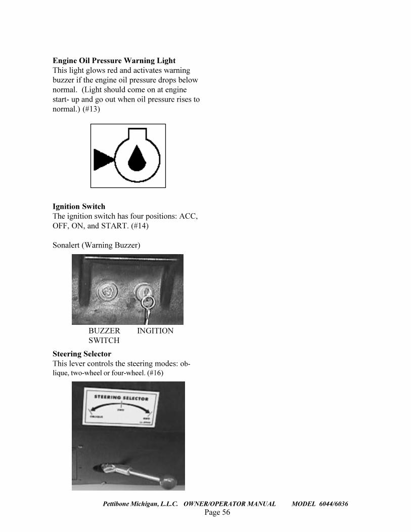
Engine Oil Pressure Warning LightThis light glows red and activates warningbuzzer if the engine oil pressure drops belownormal. (Light should come on at enginestart- up and go out when oil pressure rises tonormal.) (#13)
Ignition SwitchThe ignition switch has four positions: ACC,OFF, ON, and START. (#14)
Sonalert (Warning Buzzer)
BUZZER INGITIONSWITCH
Steering SelectorThis lever controls the steering modes: ob-lique, two-wheel or four-wheel. (#16)
Page 57Pettibone Michigan, L.L.C. OWNER/OPERATOR MANUAL MODEL 6044/6036
DISPLAY, CONTROL, OR INDICATOR
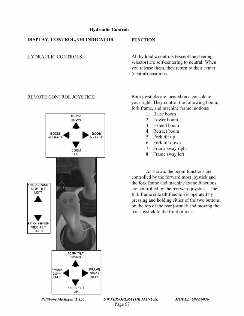
HYDRAULIC CONTROLS
REMOTE CONTROL JOYSTICK
FUNCTION
All hydraulic controls (except the steeringselector) are self-centering to neutral. Whenyou release them, they return to their center(neutral) positions.
Both joysticks are located on a console toyour right. They control the following boom,fork frame, and machine frame motions:
1. Raise boom2. Lower boom3. Extend boom4. Retract boom5. Fork tilt up6. Fork tilt down7. Frame sway right8. Frame sway left
As shown, the boom functions arecontrolled by the forward most joystick andthe fork frame and machine frame functionsare controlled by the rearward joystick. Thefork frame side tilt function is operated bypressing and holding either of the two buttonson the top of the rear joystick and moving therear joystick to the front or rear.
Hydraulic Controls
Page 58
TRAVERSE LIFT
Pettibone Michigan, L.L.C. OWNER/OPERATOR MANUAL MODEL 6044/6036
DISPLAY, CONTROL, OR INDICATOR
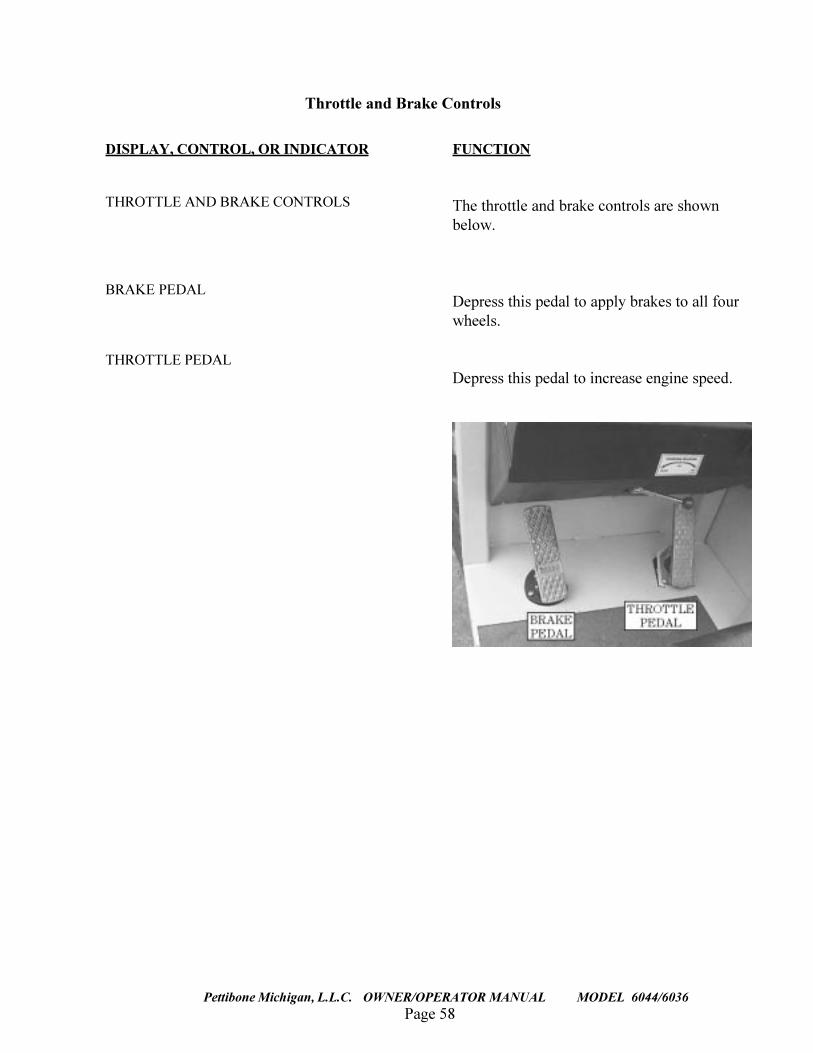
THROTTLE AND BRAKE CONTROLS
BRAKE PEDAL
THROTTLE PEDAL
FUNCTION
The throttle and brake controls are shownbelow.
Depress this pedal to apply brakes to all fourwheels.
Depress this pedal to increase engine speed.
Throttle and Brake Controls
Page 59Pettibone Michigan, L.L.C. OWNER/OPERATOR MANUAL MODEL 6044/6036
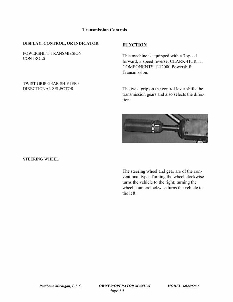
DISPLAY, CONTROL, OR INDICATOR
POWERSHIFT TRANSMISSIONCONTROLS
TWIST GRIP GEAR SHIFTER /DIRECTIONAL SELECTOR
STEERING WHEEL
FUNCTION
This machine is equipped with a 3 speedforward, 3 speed reverse, CLARK-HURTHCOMPONENTS T-12000 PowershiftTransmission.
The twist grip on the control lever shifts thetransmission gears and also selects the direc-tion.
The steering wheel and gear are of the con-ventional type. Turning the wheel clockwiseturns the vehicle to the right; turning thewheel counterclockwise turns the vehicle tothe left.
Transmission Controls
Page 60
TRAVERSE LIFT
Pettibone Michigan, L.L.C. OWNER/OPERATOR MANUAL MODEL 6044/6036
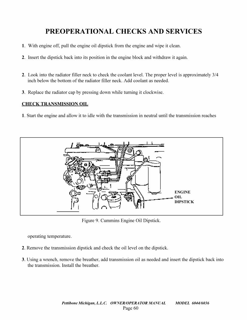
PREOPERATIONAL CHECKS AND SERVICES
1. With engine off, pull the engine oil dipstick from the engine and wipe it clean.
2. Insert the dipstick back into its position in the engine block and withdraw it again.
2. Look into the radiator filler neck to check the coolant level. The proper level is approximately 3/4inch below the bottom of the radiator filler neck. Add coolant as needed.
3. Replace the radiator cap by pressing down while turning it clockwise.
CHECK TRANSMISSION OIL
1. Start the engine and allow it to idle with the transmission in neutral until the transmission reaches
Figure 9. Cummins Engine Oil Dipstick.
ENGINEOILDIPSTICK
operating temperature.
2. Remove the transmission dipstick and check the oil level on the dipstick.
3. Using a wrench, remove the breather, add transmission oil as needed and insert the dipstick back intothe transmission. Install the breather.
Page 61Pettibone Michigan, L.L.C. OWNER/OPERATOR MANUAL MODEL 6044/6036
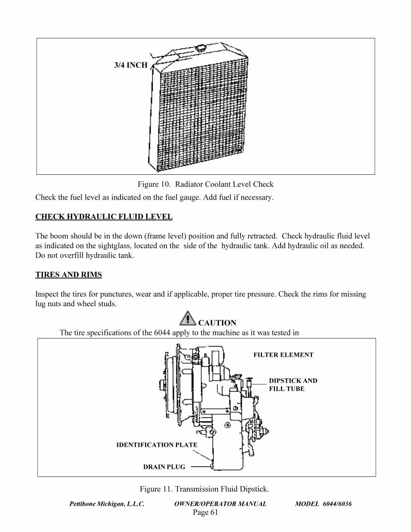
3/4 INCH
Figure 10. Radiator Coolant Level Check
Check the fuel level as indicated on the fuel gauge. Add fuel if necessary.
CHECK HYDRAULIC FLUID LEVEL
The boom should be in the down (frame level) position and fully retracted. Check hydraulic fluid levelas indicated on the sightglass, located on the side of the hydraulic tank. Add hydraulic oil as needed.Do not overfill hydraulic tank.
TIRES AND RIMS
Inspect the tires for punctures, wear and if applicable, proper tire pressure. Check the rims for missinglug nuts and wheel studs.
CAUTIONThe tire specifications of the 6044 apply to the machine as it was tested in
Figure 11. Transmission Fluid Dipstick.
FILTER ELEMENT
DIPSTICK ANDFILL TUBE
DRAIN PLUG
IDENTIFICATION PLATE
Page 62
TRAVERSE LIFT
Pettibone Michigan, L.L.C. OWNER/OPERATOR MANUAL MODEL 6044/6036
accordance with ASME B56.6A-1994. Any replacement of tires must meet orexceed these specifications for sidewall stiffness.
INSPECTION FOR LEAKS
Visually inspect the area beneath the forklift for puddles, indicating a leak. Locate the cause of the leakand correct the problem before operating the forklift. Recheck all fluid levels at this point.
GENERAL INSPECTION
Perform a walk-around inspection of the forklift, looking for loose items (tools, shop towels etc.) thatmay have been left on forklift. Remove any such items.
The following checks and services are to be performed during forklift operation:
GAUGES AND INDICATORS
Observe all gauges and indicators and be prepared to halt operation in the event of any abnormal indica-tion. Be constantly aware of the fuel level, engine coolant temperature, transmission oil temperatureand electrical system voltage.
HYDRAULIC FLUID LEVEL
Perform a daily check of the hydraulic oil level and temperature as indicated on the sightglass, locatedon the side of the hydraulic tank. Add hydraulic oil if necessary.
CHANGES IN PERFORMANCE
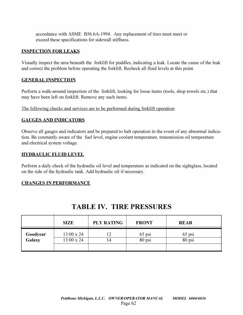
TABLE IV. TIRE PRESSURES
SIZE PLY RATING FRONT REAR
Goodyear 13:00 x 24 12 65 psi 65 psiGalaxy 13:00 x 24 14 80 psi 80 psi
Page 63Pettibone Michigan, L.L.C. OWNER/OPERATOR MANUAL MODEL 6044/6036
Be constantly alert to changes in the equipment�s operating characteristics. Such changes inperformance are sometimes an indication of a malfunction.
OPERATING INSTRUCTIONSSTARTUP AND DRIVING
CAUTIONNever operate the starter for more than 20 seconds continuously. Allow 2minutes between starting efforts. If using starting fluid for a cold weather start,inject the starting fluid only while the engine is cranking.
1. Start the engine by applying the parking brake, placing the transmission in neutral, inserting theignition key into the switch and turning the key clockwise. Release the key when the engine starts.
WARNINGThe forklift must be standing still when selecting the steering mode. Seriousinjury and/or equipment damage could occur if the mode is selected while theforklift is moving.
OPERATIONAL CHECKS & SERVICES
Page 64
TRAVERSE LIFT
Pettibone Michigan, L.L.C. OWNER/OPERATOR MANUAL MODEL 6044/6036
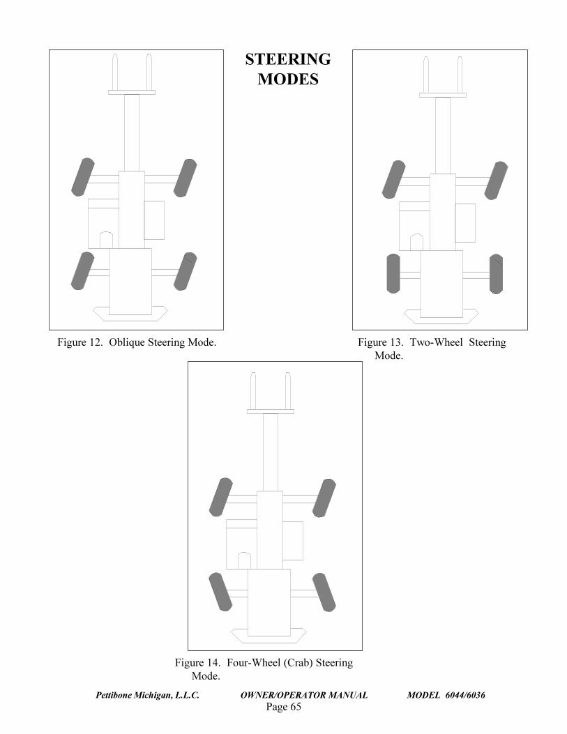
2. Determine which of the following steering modes is to be selected:
a. OBLIQUE. (Shown in Figure 12 on the following page.) In this position all four wheels willturn in the same direction. This steering mode should not be used at speeds exceeding 2MPH.
b. TWO-WHEEL STEER. (Shown in Figure 13 on the following page.) In this position onlythe front wheels will steer. Before selecting this mode, the rear wheels must be turnedstraight using the 4 WHEEL STEER mode. Use ONLY 2 WHEEL STEER mode whentravel speeds exceed 10 MPH.
c. FOUR-WHEEL (CRAB) STEER. (Shown in Figure 14 on the folling page.) In this modethe rear wheels will turn in the opposite direction from the front wheels, providing theshortest turn radius. Do not use 4 wheel steer at speeds over 10 mph.
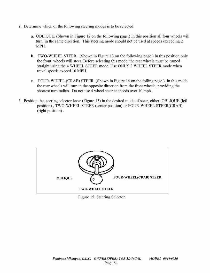
3. Position the steering selector lever (Figure 15) in the desired mode of steer, either, OBLIQUE (leftposition) , TWO-WHEEL STEER (center position) or FOUR-WHEEL STEER(CRAB)(right position) .
FOUR-WHEEL(CRAB) STEEROBLIQUE
TWO-WHEEL STEER
Figure 15. Steering Selector.
Page 65Pettibone Michigan, L.L.C. OWNER/OPERATOR MANUAL MODEL 6044/6036
Figure 12. Oblique Steering Mode.
Figure 14. Four-Wheel (Crab) SteeringMode.
Figure 13. Two-Wheel SteeringMode.
STEERINGMODES
Page 66
TRAVERSE LIFT
Pettibone Michigan, L.L.C. OWNER/OPERATOR MANUAL MODEL 6044/6036
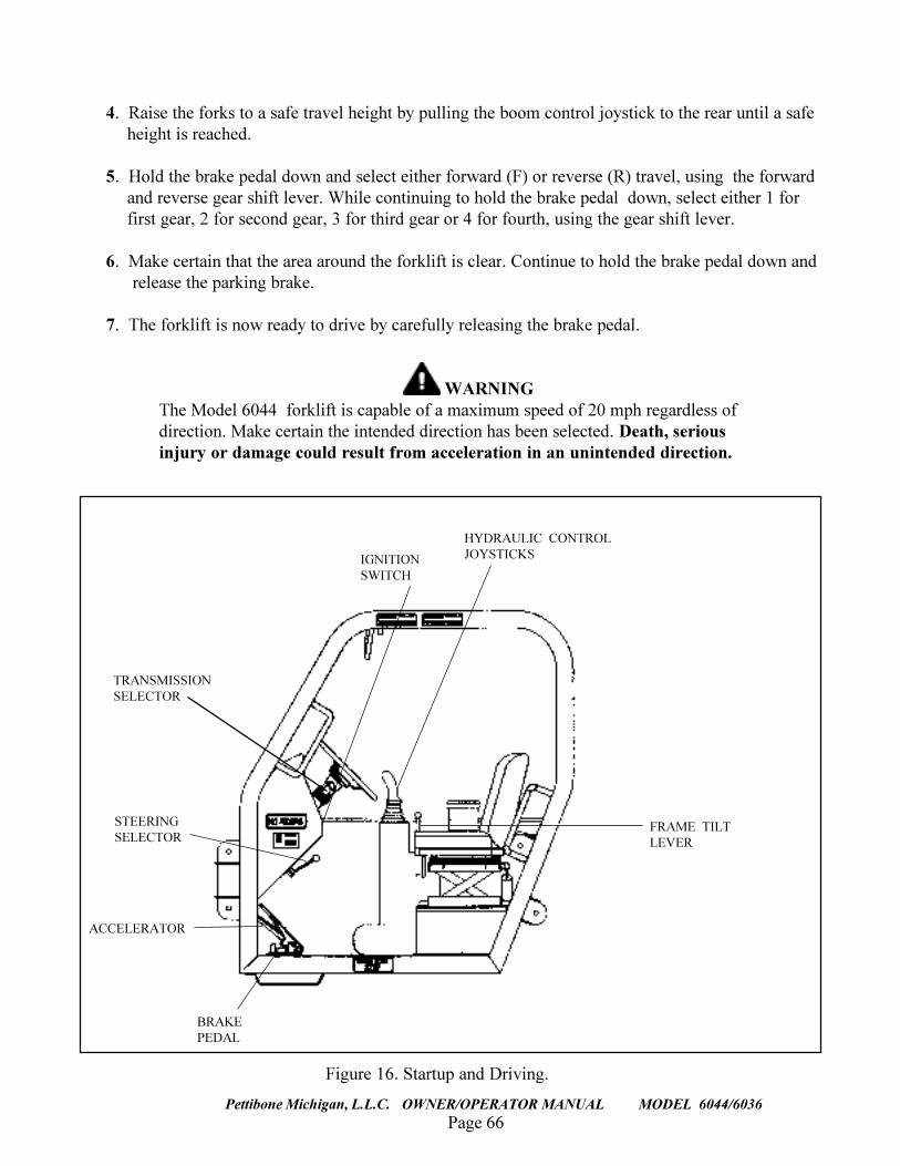
4. Raise the forks to a safe travel height by pulling the boom control joystick to the rear until a safeheight is reached.
5. Hold the brake pedal down and select either forward (F) or reverse (R) travel, using the forwardand reverse gear shift lever. While continuing to hold the brake pedal down, select either 1 forfirst gear, 2 for second gear, 3 for third gear or 4 for fourth, using the gear shift lever.
6. Make certain that the area around the forklift is clear. Continue to hold the brake pedal down andrelease the parking brake.
7. The forklift is now ready to drive by carefully releasing the brake pedal.
WARNINGThe Model 6044 forklift is capable of a maximum speed of 20 mph regardless ofdirection. Make certain the intended direction has been selected. Death, seriousinjury or damage could result from acceleration in an unintended direction.
Figure 16. Startup and Driving.
IGNITIONSWITCH
TRANSMISSIONSELECTOR
BRAKEPEDAL
STEERINGSELECTOR
HYDRAULIC CONTROLJOYSTICKS
ACCELERATOR
FRAME TILTLEVER
Page 67Pettibone Michigan, L.L.C. OWNER/OPERATOR MANUAL MODEL 6044/6036
RAISING THE LOAD
NOTERefer to Figure 16, �Startup and Driving,� for identification of componentsmentioned in this procedure.
1. Inspect every load before attempting to lift. Make certain the loads are properly bound and willnot fall apart while lifting and transporting. Also, make sure the weight of the loads are withinthe safe lifting range of the forklift.
2. Position the forklift directly and squarely in front of the load.
3. Lower the boom by pushing the front joystick forward until the forks are at the necessary level toengage the load.
4. If machine is equipped with the Fork Rotate function, level the forks by depressing and holdingeither button on the rear joystick. Press the joystick forward to rotate fork frame to the left andpull the joystick back to rotate the fork frame to the right. (See instruction decal on page 76.)
5. If necessary, adjust the width of the forks to accommodate the load.
6. To position the load for transport:a) tilt the forks back by pulling the rear joystick back without pressing any buttons,b) retract the boom by moving the front joystick to the left, andc) once the boom is down, ensure the forks are tilted back to a stable position by pulling the
rear joystick back without pressing any buttons.
7. Pull the front joystick back to lift the load only enough to clear obstacles. Keep the top of theload below eye level. The load is now ready to transport.
WARNINGDo not attempt to transport stacked loads. The top of a stacked load maynot be visible to the operator . If the load is too tall, it should be transportedin two or more moves. Failure to do so could result in death, serious injuryor damage to the equipment.
Page 68
TRAVERSE LIFT
Pettibone Michigan, L.L.C. OWNER/OPERATOR MANUAL MODEL 6044/6036
Refer to Figure 16, �Startup and Driving,� for identification of componentsmentioned in this procedure.
1. Make certain that all the steps outlined in �STARTUP AND DRIVING� have been performed.
2. Always observe the path ahead and be aware of anything to the sides of the path that may pose aproblem and act accordingly. DO NOT OVERDRIVE THE CONDITIONS.
3. Be constantly aware of the area overhead and make sure, before entering an area with limitedoverhead, that the forklift will fit. NEVER OPERATE NEAR POWER LINES.
4. Keep the load as close to the ground as possible when moving and DO NOT STOPSUDDENLY. Approach turns, uneven and/or slippery surfaces slowly. Sound horn and drive slowly
in congested areas.
WARNINGNever attempt to drive across an excessively steep incline, regardless ofcircumstances. Serious injury and/or death could otherwise result.EXERCISE GOOD JUDGEMENT.
5. Driving on inclines or unstable surfaces is unsafe but sometimes unavoidable. If drivingon an incline cannot be avoided, level the forklift by using the Frame Tilt lever as follows(see Figure 17.):
a. Pull lever to left to tilt the forklift frame to the left.
b. Pull the lever to right to tilt the forklift frame to the right.
6. When traveling on inclines, do so as follows:
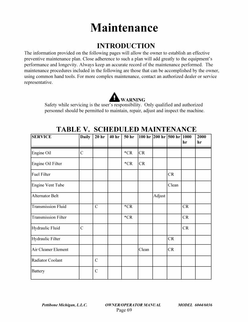
Page 69Pettibone Michigan, L.L.C. OWNER/OPERATOR MANUAL MODEL 6044/6036
INTRODUCTIONThe information provided on the following pages will allow the owner to establish an effectivepreventive maintenance plan. Close adherence to such a plan will add greatly to the equipment�sperformance and longevity. Always keep an accurate record of the maintenance performed. Themaintenance procedures included in the following are those that can be accomplished by the owner,using common hand tools. For more complex maintenance, contact an authorized dealer or servicerepresentative.
WARNINGSafety while servicing is the user�s responsibility. Only qualified and authorizedpersonnel should be permitted to maintain, repair, adjust and inspect the machine.
TABLE V. SCHEDULED MAINTENANCESERVICE Daily 20 hr 40 hr 50 hr 100 hr 200 hr 500 hr 1000 2000
hr hr
Engine Oil C *CR CR
Engine Oil Filter *CR CR
Fuel Filter CR
Engine Vent Tube Clean
Alternator Belt Adjust
Transmission Fluid C *CR CR
Transmission Filter *CR CR
Hydraulic Fluid C CR
Hydraulic Filter CR
Air Cleaner Element Clean CR
Radiator Coolant C
Battery C
Maintenance
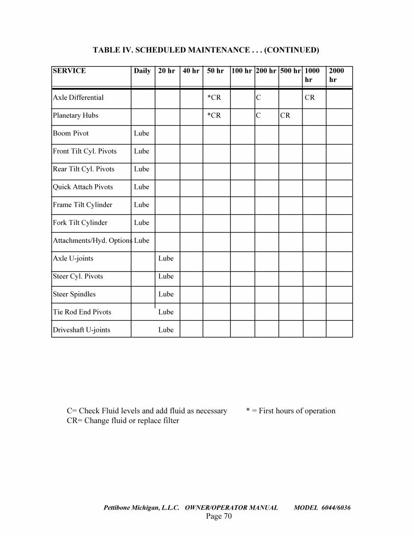
Page 70
TRAVERSE LIFT
Pettibone Michigan, L.L.C. OWNER/OPERATOR MANUAL MODEL 6044/6036
TABLE IV. SCHEDULED MAINTENANCE . . . (CONTINUED)
C= Check Fluid levels and add fluid as necessary * = First hours of operationCR= Change fluid or replace filter
SERVICE Daily 20 hr 40 hr 50 hr 100 hr 200 hr 500 hr 1000 2000hr hr
Axle Differential *CR C CR
Planetary Hubs *CR C CR
Boom Pivot Lube
Front Tilt Cyl. Pivots Lube
Rear Tilt Cyl. Pivots Lube
Quick Attach Pivots Lube
Frame Tilt Cylinder Lube
Fork Tilt Cylinder Lube
Attachments/Hyd. Options Lube
Axle U-joints Lube
Steer Cyl. Pivots Lube
Steer Spindles Lube
Tie Rod End Pivots Lube
Driveshaft U-joints Lube
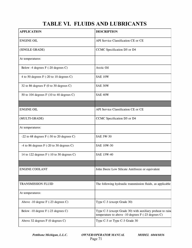
Page 71Pettibone Michigan, L.L.C. OWNER/OPERATOR MANUAL MODEL 6044/6036
TABLE VI. FLUIDS AND LUBRICANTS#22.+%#6+10 &'5%4+26+10
'0)+0'�1+. #2+�5GTXKEG�%NCUUKHKECVKQP�%'�QT�%'
5+0).'�)4#&'� %%/%�5RGEKHKECVKQP�&��QT�&�
#V�VGORGTCVWTGU�
��$GNQY����FGITGGU�(�����FGITGGU�%� #TEVKE�1KN
����VQ����FGITGGU�(�����VQ����FGITGGU�%� 5#'���9
�����VQ����FGITGGU�(���VQ����FGITGGU�%� 5#'���9
�����VQ�����FGITGGU�(����VQ����FGITGGU�%� 5#'���9
'0)+0'�1+. #2+�5GTXKEG�%NCUUKHKECVKQP�%'�QT�%'
/7.6+�)4#&'� %%/%�5RGEKHKECVKQP�&��QT�&�
#V�VGORGTCVWTGU�
������VQ����FGITGGU�(�����VQ����FGITGGU�%� 5#'��9���
�����VQ����FGITGGU�(�����VQ����FGITGGU�%� 5#'���9���
�����VQ�����FGITGGU�(�����VQ����FGITGGU�%� 5#'���9���
'0)+0'�%11.#06 ,QJP�&GGTG�.QY�5KNKECVG�#PVKHTGG\G�QT�GSWKXCNGPV
64#05/+55+10�(.7+& 6JG�HQNNQYKPI�J[FTCWNKE�VTCPUOKUUKQP�HNWKFU��CU�CRRNKECDNG
#V�VGORGTCVWTGU�
��#DQXG�����FGITGG�(�����FGITGGU�%� 6[RG�%���GZEGRV�)TCFG����
��$GNQY�����FGITGG�(�����FGITGGU�%� 6[RG�%���GZEGRV�)TCFG�����YKVJ�CWZKNKCT[�RTGJGCV�VQ�TCKUGVGORGTCVWTG�VQ�CDQXG�����FGITGGU�(�����FGITGGU�%�
��#DQXG����FGITGGU�(���FGITGGU�%� 6[RG�%���QT�6[RG�%���)TCFG���
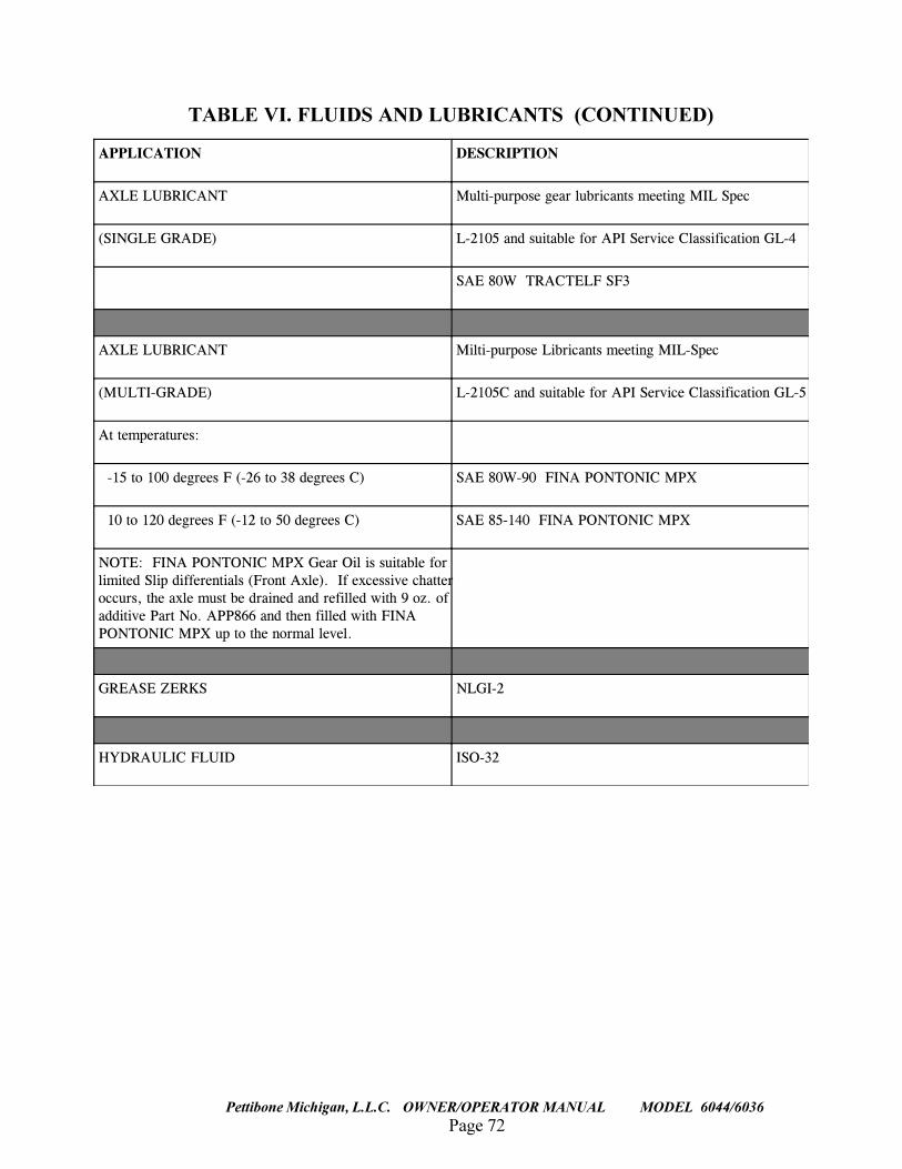
Page 72
TRAVERSE LIFT
Pettibone Michigan, L.L.C. OWNER/OPERATOR MANUAL MODEL 6044/6036
TABLE VI. FLUIDS AND LUBRICANTS (CONTINUED)
#22.+%#6+10 &'5%4+26+10
#:.'�.7$4+%#06 /WNVK�RWTRQUG�IGCT�NWDTKECPVU�OGGVKPI�/+.�5RGE
5+0).'�)4#&'� .������CPF�UWKVCDNG�HQT�#2+�5GTXKEG�%NCUUKHKECVKQP�).��
5#'���9��64#%6'.(�5(�
#:.'�.7$4+%#06 /KNVK�RWTRQUG�.KDTKECPVU�OGGVKPI�/+.�5RGE
/7.6+�)4#&'� .�����%�CPF�UWKVCDNG�HQT�#2+�5GTXKEG�%NCUUKHKECVKQP�).��
#V�VGORGTCVWTGU�
������VQ�����FGITGGU�(�����VQ����FGITGGU�%� 5#'���9�����(+0#�210610+%�/2:
�����VQ�����FGITGGU�(�����VQ����FGITGGU�%� 5#'���������(+0#�210610+%�/2:
016'���(+0#�210610+%�/2:�)GCT�1KN�KU�UWKVCDNG�HQTNKOKVGF�5NKR�FKHHGTGPVKCNU�(TQPV�#ZNG����+H�GZEGUUKXG�EJCVVGTQEEWTU��VJG�CZNG�OWUV�DG�FTCKPGF�CPF�TGHKNNGF�YKVJ���Q\��QHCFFKVKXG�2CTV�0Q��#22����CPF�VJGP�HKNNGF�YKVJ�(+0#210610+%�/2:�WR�VQ�VJG�PQTOCN�NGXGN�
)4'#5'�<'4-5 0.)+��
*;&4#7.+%�(.7+& +51���
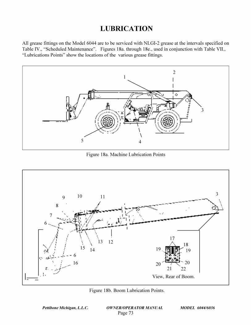
Page 73Pettibone Michigan, L.L.C. OWNER/OPERATOR MANUAL MODEL 6044/6036
LUBRICATION
All grease fittings on the Model 6044 are to be serviced with NLGI-2 grease at the intervals specified onTable IV., �Scheduled Maintenance�. Figures 18a. through 18e., used in conjunction with Table VII.,�Lubrications Points� show the locations of the various grease fittings.
Figure 18a. Machine Lubrication Points
Figure 18b. Boom Lubrication Points.
12
5
3
4
3
View, Rear of Boom.
8
7
11109
17
16
6
6
15 14
13 12 1819
202221
20
19
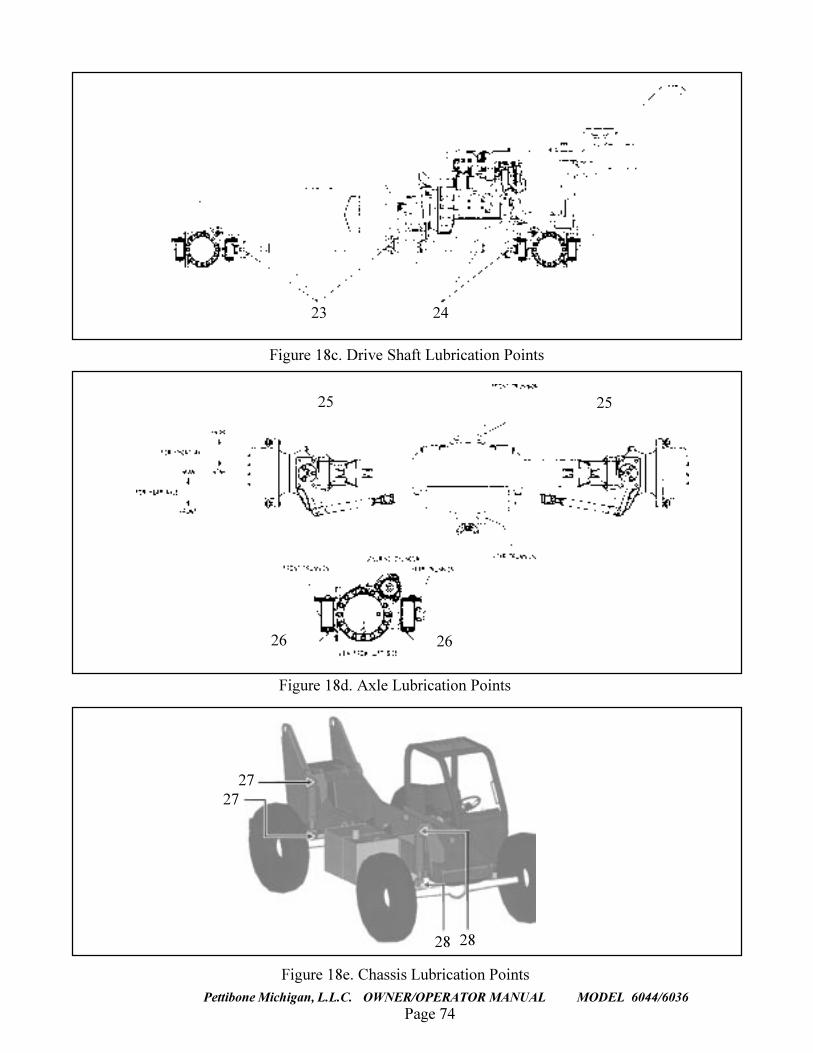
Page 74
TRAVERSE LIFT
Pettibone Michigan, L.L.C. OWNER/OPERATOR MANUAL MODEL 6044/6036
2423
Figure 18c. Drive Shaft Lubrication Points
Figure 18d. Axle Lubrication Points
2626
25 25
2828
2727
Figure 18e. Chassis Lubrication Points
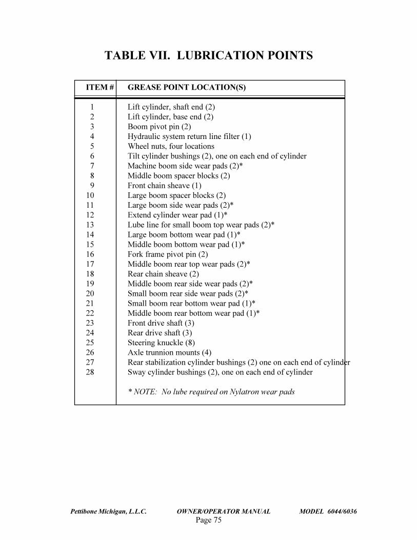
Page 75Pettibone Michigan, L.L.C. OWNER/OPERATOR MANUAL MODEL 6044/6036
TABLE VII. LUBRICATION POINTS
ITEM # GREASE POINT LOCATION(S)
1 Lift cylinder, shaft end (2) 2 Lift cylinder, base end (2) 3 Boom pivot pin (2) 4 Hydraulic system return line filter (1) 5 Wheel nuts, four locations 6 Tilt cylinder bushings (2), one on each end of cylinder 7 Machine boom side wear pads (2)* 8 Middle boom spacer blocks (2) 9 Front chain sheave (1)10 Large boom spacer blocks (2)11 Large boom side wear pads (2)*12 Extend cylinder wear pad (1)*13 Lube line for small boom top wear pads (2)*14 Large boom bottom wear pad (1)*15 Middle boom bottom wear pad (1)*16 Fork frame pivot pin (2)17 Middle boom rear top wear pads (2)*18 Rear chain sheave (2)19 Middle boom rear side wear pads (2)*20 Small boom rear side wear pads (2)*21 Small boom rear bottom wear pad (1)*22 Middle boom rear bottom wear pad (1)*23 Front drive shaft (3)24 Rear drive shaft (3)25 Steering knuckle (8)26 Axle trunnion mounts (4)27 Rear stabilization cylinder bushings (2) one on each end of cylinder28 Sway cylinder bushings (2), one on each end of cylinder
* NOTE: No lube required on Nylatron wear pads
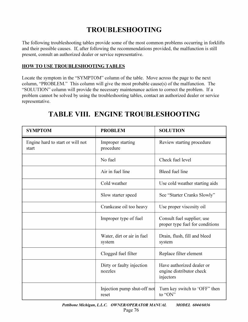
Page 76
TRAVERSE LIFT
Pettibone Michigan, L.L.C. OWNER/OPERATOR MANUAL MODEL 6044/6036
TROUBLESHOOTING
The following troubleshooting tables provide some of the most common problems occurring in forkliftsand their possible causes. If, after following the recommendations provided, the malfunction is stillpresent, consult an authorized dealer or service representative.
HOW TO USE TROUBLESHOOTING TABLES
Locate the symptom in the �SYMPTOM� column of the table. Move across the page to the nextcolumn, �PROBLEM.� This column will give the most probable cause(s) of the malfunction. The�SOLUTION� column will provide the necessary maintenance action to correct the problem. If aproblem cannot be solved by using the troubleshooting tables, contact an authorized dealer or servicerepresentative.
TABLE VIII. ENGINE TROUBLESHOOTING
SYMPTOM PROBLEM SOLUTION
Engine hard to start or will not Improper starting Review starting procedurestart procedure
No fuel Check fuel level
Air in fuel line Bleed fuel line
Cold weather Use cold weather starting aids
Slow starter speed See �Starter Cranks Slowly�
Crankcase oil too heavy Use proper viscosity oil
Improper type of fuel Consult fuel supplier; useproper type fuel for conditions
Water, dirt or air in fuel Drain, flush, fill and bleedsystem system
Clogged fuel filter Replace filter element
Dirty or faulty injection Have authorized dealer ornozzles engine distributor check
injectors
Injection pump shut-off not Turn key switch to �OFF� thenreset to �ON�
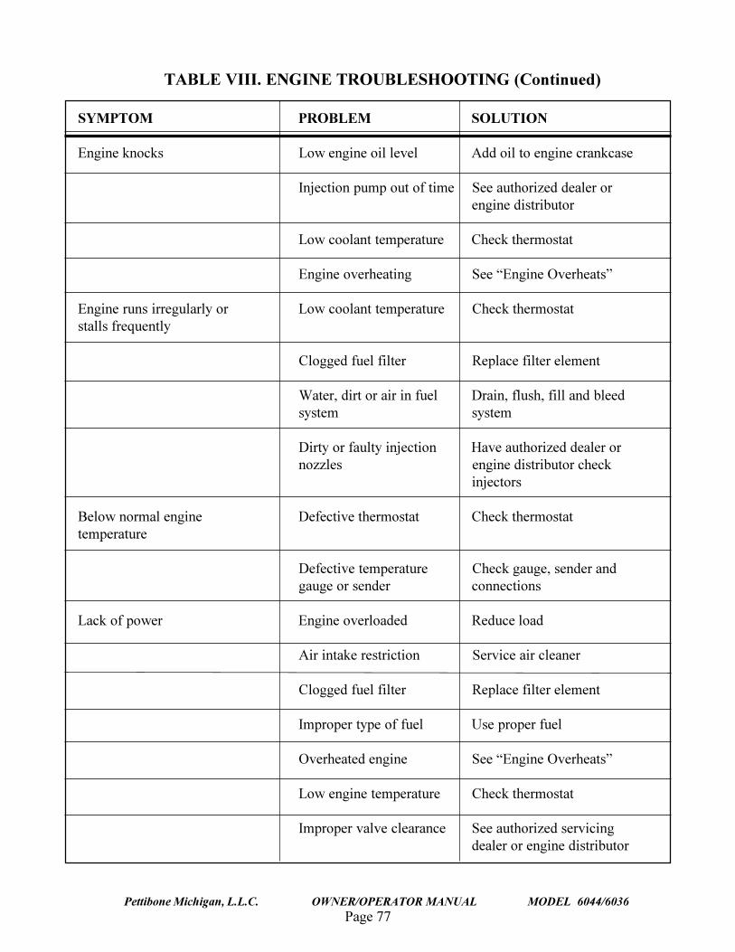
Page 77Pettibone Michigan, L.L.C. OWNER/OPERATOR MANUAL MODEL 6044/6036
SYMPTOM PROBLEM SOLUTION
Engine knocks Low engine oil level Add oil to engine crankcase
Injection pump out of time See authorized dealer orengine distributor
Low coolant temperature Check thermostat
Engine overheating See �Engine Overheats�
Engine runs irregularly or Low coolant temperature Check thermostatstalls frequently
Clogged fuel filter Replace filter element
Water, dirt or air in fuel Drain, flush, fill and bleedsystem system
Dirty or faulty injection Have authorized dealer ornozzles engine distributor check
injectors
Below normal engine Defective thermostat Check thermostattemperature
Defective temperature Check gauge, sender andgauge or sender connections
Lack of power Engine overloaded Reduce load
Air intake restriction Service air cleaner
Clogged fuel filter Replace filter element
Improper type of fuel Use proper fuel
Overheated engine See �Engine Overheats�
Low engine temperature Check thermostat
Improper valve clearance See authorized servicingdealer or engine distributor
TABLE VIII. ENGINE TROUBLESHOOTING (Continued)
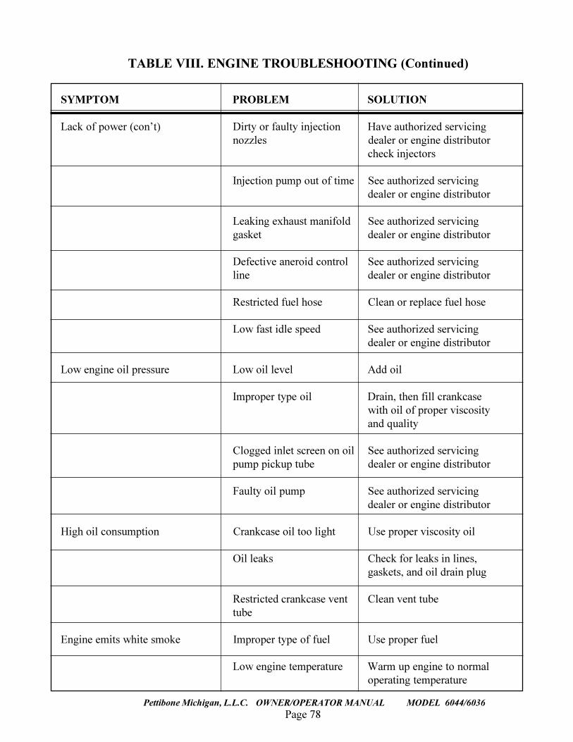
Page 78
TRAVERSE LIFT
Pettibone Michigan, L.L.C. OWNER/OPERATOR MANUAL MODEL 6044/6036
SYMPTOM PROBLEM SOLUTION
Lack of power (con�t) Dirty or faulty injection Have authorized servicingnozzles dealer or engine distributor
check injectors
Injection pump out of time See authorized servicingdealer or engine distributor
Leaking exhaust manifold See authorized servicinggasket dealer or engine distributor
Defective aneroid control See authorized servicingline dealer or engine distributor
Restricted fuel hose Clean or replace fuel hose
Low fast idle speed See authorized servicingdealer or engine distributor
Low engine oil pressure Low oil level Add oil
Improper type oil Drain, then fill crankcasewith oil of proper viscosityand quality
Clogged inlet screen on oil See authorized servicingpump pickup tube dealer or engine distributor
Faulty oil pump See authorized servicingdealer or engine distributor
High oil consumption Crankcase oil too light Use proper viscosity oil
Oil leaks Check for leaks in lines,gaskets, and oil drain plug
Restricted crankcase vent Clean vent tubetube
Engine emits white smoke Improper type of fuel Use proper fuel
Low engine temperature Warm up engine to normaloperating temperature
TABLE VIII. ENGINE TROUBLESHOOTING (Continued)
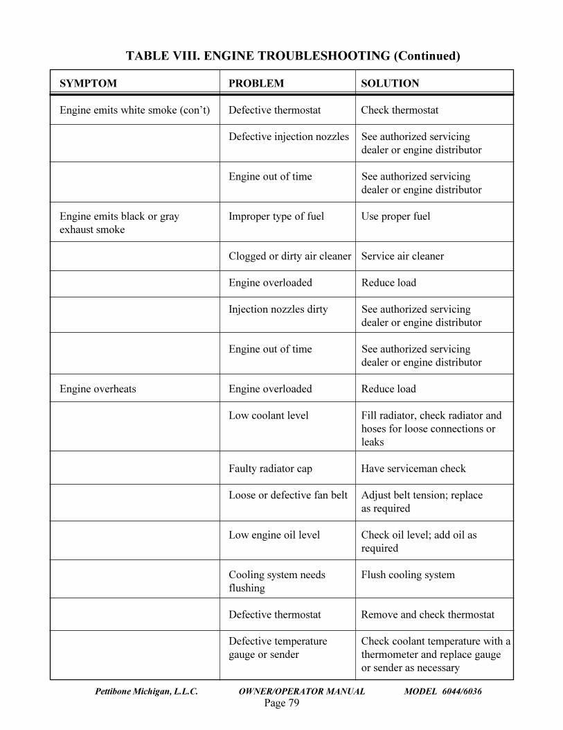
Page 79Pettibone Michigan, L.L.C. OWNER/OPERATOR MANUAL MODEL 6044/6036
SYMPTOM PROBLEM SOLUTION
Engine emits white smoke (con�t) Defective thermostat Check thermostat
Defective injection nozzles See authorized servicingdealer or engine distributor
Engine out of time See authorized servicingdealer or engine distributor
Engine emits black or gray Improper type of fuel Use proper fuelexhaust smoke
Clogged or dirty air cleaner Service air cleaner
Engine overloaded Reduce load
Injection nozzles dirty See authorized servicingdealer or engine distributor
Engine out of time See authorized servicingdealer or engine distributor
Engine overheats Engine overloaded Reduce load
Low coolant level Fill radiator, check radiator andhoses for loose connections orleaks
Faulty radiator cap Have serviceman check
Loose or defective fan belt Adjust belt tension; replaceas required
Low engine oil level Check oil level; add oil asrequired
Cooling system needs Flush cooling systemflushing
Defective thermostat Remove and check thermostat
Defective temperature Check coolant temperature with agauge or sender thermometer and replace gauge
or sender as necessary
TABLE VIII. ENGINE TROUBLESHOOTING (Continued)
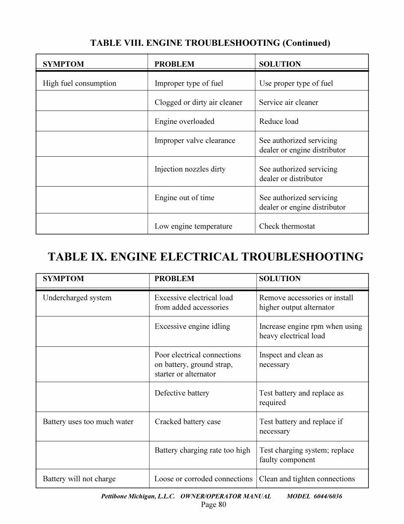
Page 80
TRAVERSE LIFT
Pettibone Michigan, L.L.C. OWNER/OPERATOR MANUAL MODEL 6044/6036
SYMPTOM PROBLEM SOLUTION
High fuel consumption Improper type of fuel Use proper type of fuel
Clogged or dirty air cleaner Service air cleaner
Engine overloaded Reduce load
Improper valve clearance See authorized servicingdealer or engine distributor
Injection nozzles dirty See authorized servicingdealer or distributor
Engine out of time See authorized servicingdealer or engine distributor
Low engine temperature Check thermostat
TABLE IX. ENGINE ELECTRICAL TROUBLESHOOTING
SYMPTOM PROBLEM SOLUTION
Undercharged system Excessive electrical load Remove accessories or installfrom added accessories higher output alternator
Excessive engine idling Increase engine rpm when usingheavy electrical load
Poor electrical connections Inspect and clean ason battery, ground strap, necessarystarter or alternator
Defective battery Test battery and replace asrequired
Battery uses too much water Cracked battery case Test battery and replace ifnecessary
Battery charging rate too high Test charging system; replacefaulty component
Battery will not charge Loose or corroded connections Clean and tighten connections
TABLE VIII. ENGINE TROUBLESHOOTING (Continued)
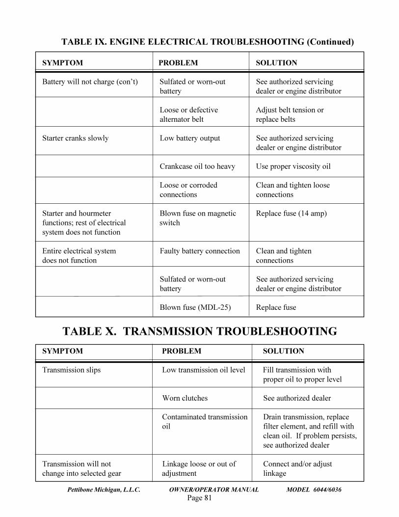
Page 81Pettibone Michigan, L.L.C. OWNER/OPERATOR MANUAL MODEL 6044/6036
SYMPTOM PROBLEM SOLUTION
Battery will not charge (con�t) Sulfated or worn-out See authorized servicingbattery dealer or engine distributor
Loose or defective Adjust belt tension oralternator belt replace belts
Starter cranks slowly Low battery output See authorized servicingdealer or engine distributor
Crankcase oil too heavy Use proper viscosity oil
Loose or corroded Clean and tighten looseconnections connections
Starter and hourmeter Blown fuse on magnetic Replace fuse (14 amp)functions; rest of electrical switchsystem does not function
Entire electrical system Faulty battery connection Clean and tightendoes not function connections
Sulfated or worn-out See authorized servicingbattery dealer or engine distributor
Blown fuse (MDL-25) Replace fuse
TABLE X. TRANSMISSION TROUBLESHOOTING
SYMPTOM PROBLEM SOLUTION
Transmission slips Low transmission oil level Fill transmission withproper oil to proper level
Worn clutches See authorized dealer
Contaminated transmission Drain transmission, replaceoil filter element, and refill with
clean oil. If problem persists,see authorized dealer
Transmission will not Linkage loose or out of Connect and/or adjustchange into selected gear adjustment linkage
TABLE IX. ENGINE ELECTRICAL TROUBLESHOOTING (Continued)
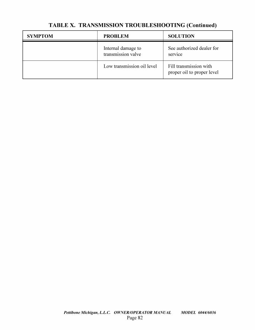
Page 82
TRAVERSE LIFT
Pettibone Michigan, L.L.C. OWNER/OPERATOR MANUAL MODEL 6044/6036
SYMPTOM PROBLEM SOLUTION
Internal damage to See authorized dealer fortransmission valve service
Low transmission oil level Fill transmission withproper oil to proper level
TABLE X. TRANSMISSION TROUBLESHOOTING (Continued)
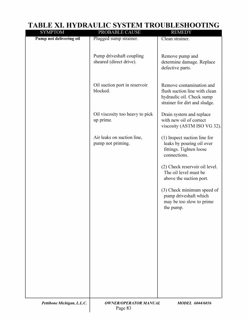
Page 83Pettibone Michigan, L.L.C. OWNER/OPERATOR MANUAL MODEL 6044/6036
TABLE XI. HYDRAULIC SYSTEM TROUBLESHOOTING
Pump not delivering oil Plugged sump strainer.
Pump driveshaft couplingsheared (direct drive).
Oil suction port in reservoirblocked.
Oil viscosity too heavy to pickup prime.
Air leaks on suction line,pump not priming.
Clean strainer.
Remove pump anddetermine damage. Replacedefective parts.
Remove contamination andflush suction line with cleanhydraulic oil. Check sumpstrainer for dirt and sludge.
Drain system and replacewith new oil of correctviscosity (ASTM ISO VG 32).
(1) Inspect suction line for leaks by pouring oil over fittings. Tighten loose connections.
(2) Check reservoir oil level. The oil level must be above the suction port.
(3) Check minimum speed of pump driveshaft which may be too slow to prime the pump.
SYMPTOM PROBABLE CAUSE REMEDY
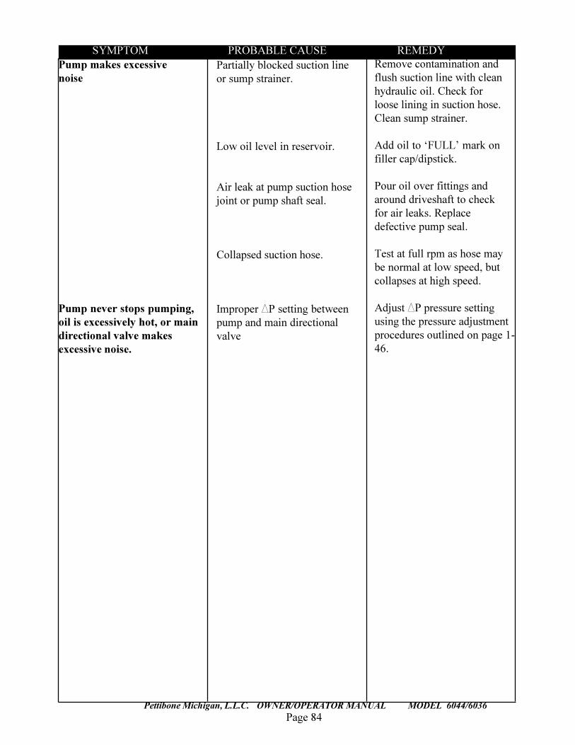
Page 84
TRAVERSE LIFT
Pettibone Michigan, L.L.C. OWNER/OPERATOR MANUAL MODEL 6044/6036
Pump makes excessivenoise
Pump never stops pumping,oil is excessively hot, or maindirectional valve makesexcessive noise.
Partially blocked suction lineor sump strainer.
Low oil level in reservoir.
Air leak at pump suction hosejoint or pump shaft seal.
Collapsed suction hose.
Improper DP setting betweenpump and main directionalvalve
Remove contamination andflush suction line with cleanhydraulic oil. Check forloose lining in suction hose.Clean sump strainer.
Add oil to �FULL� mark onfiller cap/dipstick.
Pour oil over fittings andaround driveshaft to checkfor air leaks. Replacedefective pump seal.
Test at full rpm as hose maybe normal at low speed, butcollapses at high speed.
Adjust DP pressure settingusing the pressure adjustmentprocedures outlined on page 1-46.
SYMPTOM PROBABLE CAUSE REMEDY
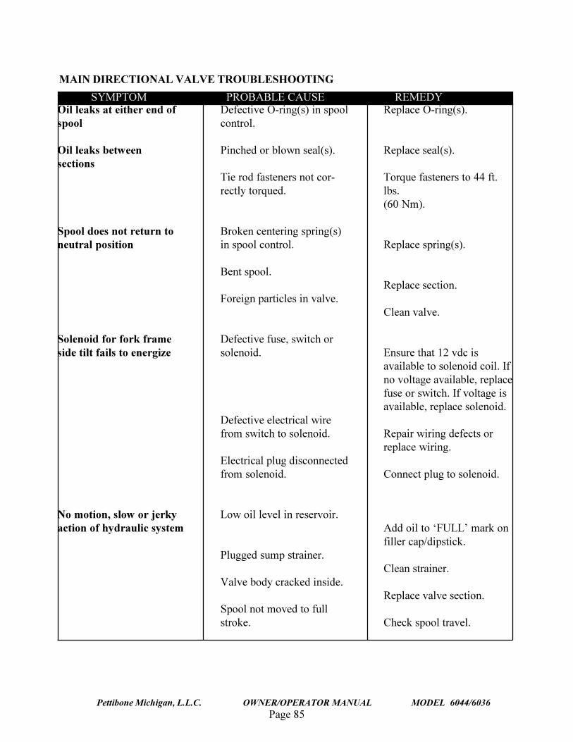
Page 85Pettibone Michigan, L.L.C. OWNER/OPERATOR MANUAL MODEL 6044/6036
Oil leaks at either end ofspool
Oil leaks betweensections
Spool does not return toneutral position
Solenoid for fork frameside tilt fails to energize
No motion, slow or jerkyaction of hydraulic system
Defective O-ring(s) in spoolcontrol.
Pinched or blown seal(s).
Tie rod fasteners not cor-rectly torqued.
Broken centering spring(s)in spool control.
Bent spool.
Foreign particles in valve.
Defective fuse, switch orsolenoid.
Defective electrical wirefrom switch to solenoid.
Electrical plug disconnectedfrom solenoid.
Low oil level in reservoir.
Plugged sump strainer.
Valve body cracked inside.
Spool not moved to fullstroke.
Replace O-ring(s).
Replace seal(s).
Torque fasteners to 44 ft.lbs.(60 Nm).
Replace spring(s).
Replace section.
Clean valve.
Ensure that 12 vdc isavailable to solenoid coil. Ifno voltage available, replacefuse or switch. If voltage isavailable, replace solenoid.
Repair wiring defects orreplace wiring.
Connect plug to solenoid.
Add oil to �FULL� mark onfiller cap/dipstick.
Clean strainer.
Replace valve section.
Check spool travel.
SYMPTOM PROBABLE CAUSE REMEDY
MAIN DIRECTIONAL VALVE TROUBLESHOOTING
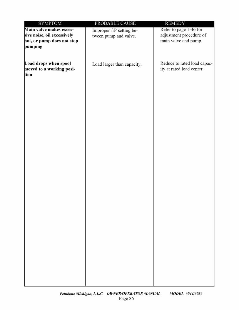
Page 86
TRAVERSE LIFT
Pettibone Michigan, L.L.C. OWNER/OPERATOR MANUAL MODEL 6044/6036
Main valve makes exces-sive noise, oil excessivelyhot, or pump does not stoppumping
Load drops when spoolmoved to a working posi-tion
Improper DP setting be-tween pump and valve.
Load larger than capacity.
Refer to page 1-46 foradjustment procedure ofmain valve and pump.
Reduce to rated load capac-ity at rated load center.
SYMPTOM PROBABLE CAUSE REMEDY
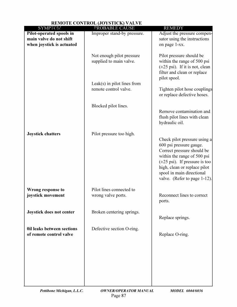
Page 87Pettibone Michigan, L.L.C. OWNER/OPERATOR MANUAL MODEL 6044/6036
Pilot-operated spools inmain valve do not shiftwhen joystick is actuated
Joystick chatters
Wrong response tojoystick movement
Joystick does not center
0il leaks between sectionsof remote control valve
Improper stand-by pressure.
Not enough pilot pressuresupplied to main valve.
Leak(s) in pilot lines fromremote control valve.
Blocked pilot lines.
Pilot pressure too high.
Pilot lines connected towrong valve ports.
Broken centering springs.
Defective section O-ring.
Adjust the pressure compen-sator using the instructionson page 1-xx.
Pilot pressure should bewithin the range of 500 psi(±25 psi). If it is not, cleanfilter and clean or replacepilot spool.
Tighten pilot hose couplingsor replace defective hoses.
Remove contamination andflush pilot lines with cleanhydraulic oil.
Check pilot pressure using a600 psi pressure gauge.Correct pressure should bewithin the range of 500 psi(±25 psi). If pressure is toohigh, clean or replace pilotspool in main directionalvalve. (Refer to page 1-12).
Reconnect lines to correctports.
Replace springs.
Replace O-ring.
SYMPTOM PROBABLE CAUSE REMEDYREMOTE CONTROL (JOYSTICK) VALVETROUBLESHOOTING
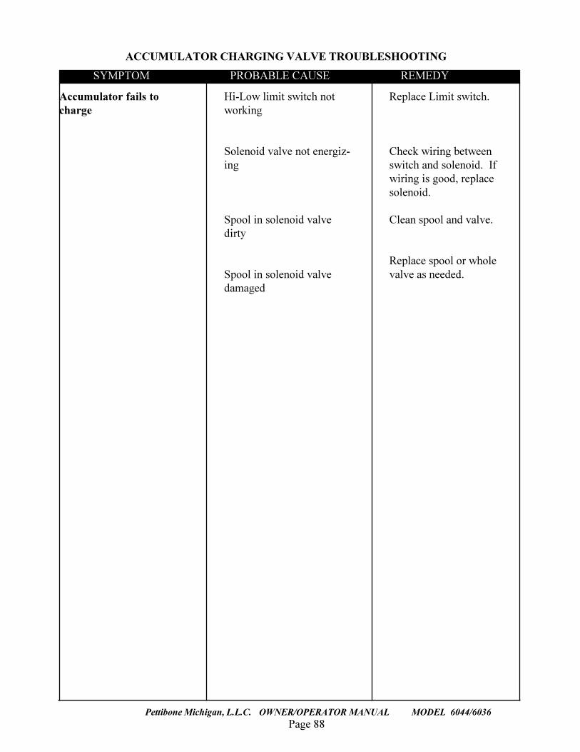
Page 88
TRAVERSE LIFT
Pettibone Michigan, L.L.C. OWNER/OPERATOR MANUAL MODEL 6044/6036
Accumulator fails tocharge
Hi-Low limit switch notworking
Solenoid valve not energiz-ing
Spool in solenoid valvedirty
Spool in solenoid valvedamaged
Replace Limit switch.
Check wiring betweenswitch and solenoid. Ifwiring is good, replacesolenoid.
Clean spool and valve.
Replace spool or wholevalve as needed.
SYMPTOM PROBABLE CAUSE REMEDY
ACCUMULATOR CHARGING VALVE TROUBLESHOOTING
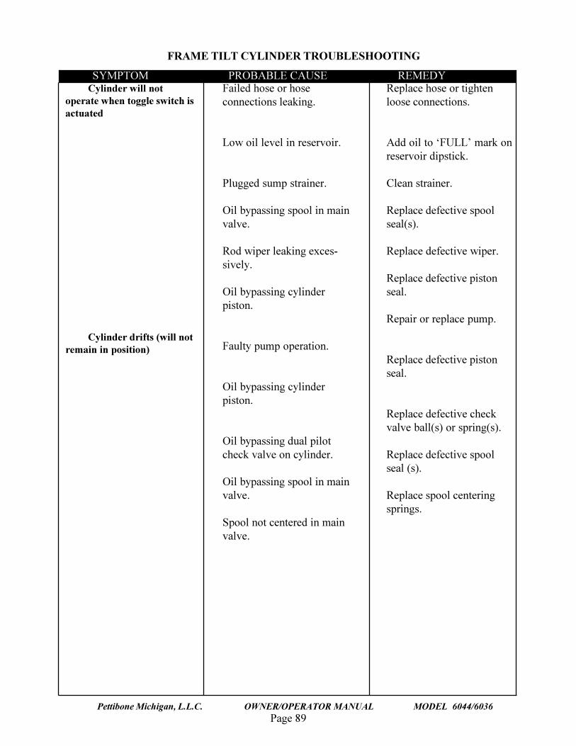
Page 89Pettibone Michigan, L.L.C. OWNER/OPERATOR MANUAL MODEL 6044/6036
Cylinder will notoperate when toggle switch isactuated
Cylinder drifts (will notremain in position)
Failed hose or hoseconnections leaking.
Low oil level in reservoir.
Plugged sump strainer.
Oil bypassing spool in mainvalve.
Rod wiper leaking exces-sively.
Oil bypassing cylinderpiston.
Faulty pump operation.
Oil bypassing cylinderpiston.
Oil bypassing dual pilotcheck valve on cylinder.
Oil bypassing spool in mainvalve.
Spool not centered in mainvalve.
Replace hose or tightenloose connections.
Add oil to �FULL� mark onreservoir dipstick.
Clean strainer.
Replace defective spoolseal(s).
Replace defective wiper.
Replace defective pistonseal.
Repair or replace pump.
Replace defective pistonseal.
Replace defective checkvalve ball(s) or spring(s).
Replace defective spoolseal (s).
Replace spool centeringsprings.
SYMPTOM PROBABLE CAUSE REMEDY
FRAME TILT CYLINDER TROUBLESHOOTING
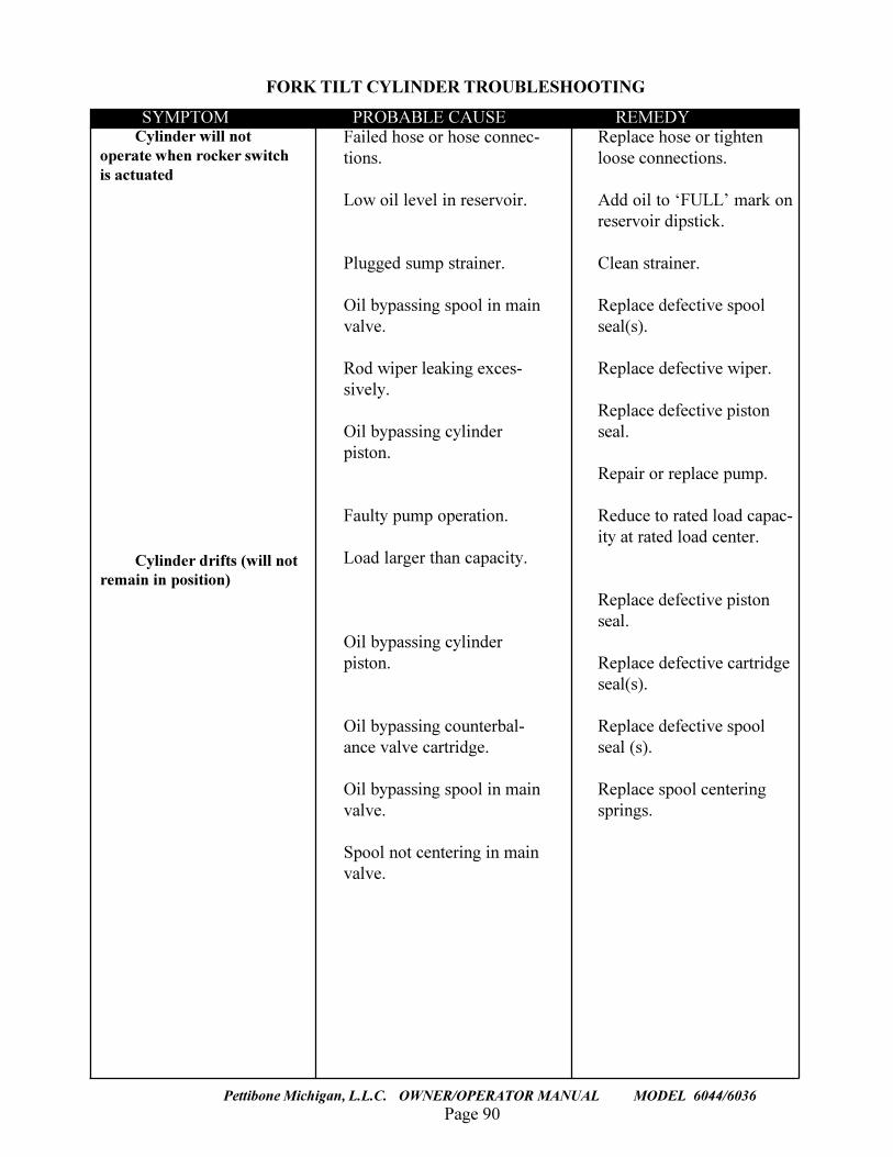
Page 90
TRAVERSE LIFT
Pettibone Michigan, L.L.C. OWNER/OPERATOR MANUAL MODEL 6044/6036
Cylinder will notoperate when rocker switchis actuated
Cylinder drifts (will notremain in position)
Failed hose or hose connec-tions.
Low oil level in reservoir.
Plugged sump strainer.
Oil bypassing spool in mainvalve.
Rod wiper leaking exces-sively.
Oil bypassing cylinderpiston.
Faulty pump operation.
Load larger than capacity.
Oil bypassing cylinderpiston.
Oil bypassing counterbal-ance valve cartridge.
Oil bypassing spool in mainvalve.
Spool not centering in mainvalve.
Replace hose or tightenloose connections.
Add oil to �FULL� mark onreservoir dipstick.
Clean strainer.
Replace defective spoolseal(s).
Replace defective wiper.
Replace defective pistonseal.
Repair or replace pump.
Reduce to rated load capac-ity at rated load center.
Replace defective pistonseal.
Replace defective cartridgeseal(s).
Replace defective spoolseal (s).
Replace spool centeringsprings.
SYMPTOM PROBABLE CAUSE REMEDY
FORK TILT CYLINDER TROUBLESHOOTING
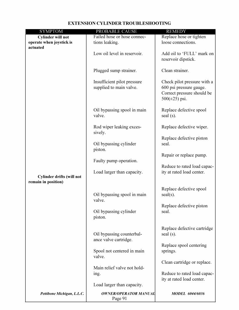
Page 91Pettibone Michigan, L.L.C. OWNER/OPERATOR MANUAL MODEL 6044/6036
Cylinder will notoperate when joystick isactuated
Cylinder drifts (will notremain in position)
Failed hose or hose connec-tions leaking.
Low oil level in reservoir.
Plugged sump strainer.
Insufficient pilot pressuresupplied to main valve.
Oil bypassing spool in mainvalve.
Rod wiper leaking exces-sively.
Oil bypassing cylinderpiston.
Faulty pump operation.
Load larger than capacity.
Oil bypassing spool in mainvalve.
Oil bypassing cylinderpiston.
Oil bypassing counterbal-ance valve cartridge.
Spool not centered in mainvalve.
Main relief valve not hold-ing.
Load larger than capacity.
Replace hose or tightenloose connections.
Add oil to �FULL� mark onreservoir dipstick.
Clean strainer.
Check pilot pressure with a600 psi pressure gauge.Correct pressure should be500(±25) psi.
Replace defective spoolseal (s).
Replace defective wiper.
Replace defective pistonseal.
Repair or replace pump.
Reduce to rated load capac-ity at rated load center.
Replace defective spoolseal(s).
Replace defective pistonseal.
Replace defective cartridgeseal (s).
Replace spool centeringsprings.
Clean cartridge or replace.
Reduce to rated load capac-ity at rated load center.
SYMPTOM PROBABLE CAUSE REMEDY
EXTENSION CYLINDER TROUBLESHOOTING
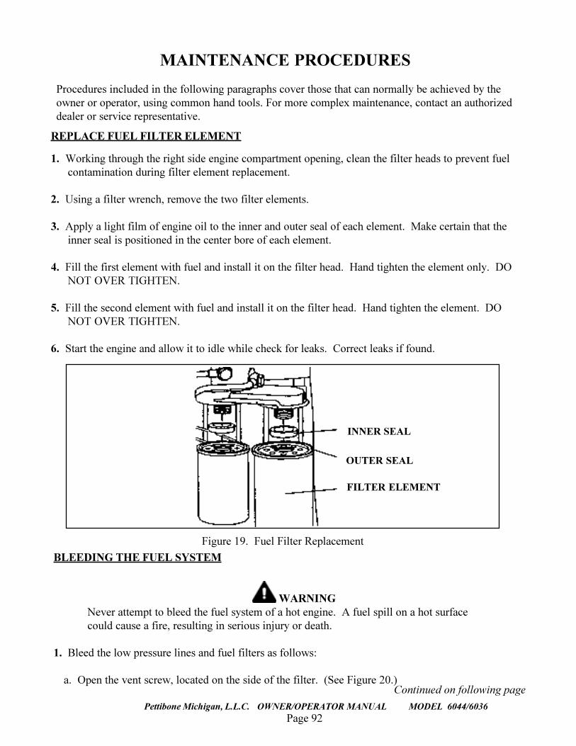
Page 92
TRAVERSE LIFT
Pettibone Michigan, L.L.C. OWNER/OPERATOR MANUAL MODEL 6044/6036
REPLACE FUEL FILTER ELEMENT
1. Working through the right side engine compartment opening, clean the filter heads to prevent fuelcontamination during filter element replacement.
2. Using a filter wrench, remove the two filter elements.
3. Apply a light film of engine oil to the inner and outer seal of each element. Make certain that theinner seal is positioned in the center bore of each element.
4. Fill the first element with fuel and install it on the filter head. Hand tighten the element only. DONOT OVER TIGHTEN.
5. Fill the second element with fuel and install it on the filter head. Hand tighten the element. DONOT OVER TIGHTEN.
6. Start the engine and allow it to idle while check for leaks. Correct leaks if found.
MAINTENANCE PROCEDURES
Procedures included in the following paragraphs cover those that can normally be achieved by theowner or operator, using common hand tools. For more complex maintenance, contact an authorizeddealer or service representative.
BLEEDING THE FUEL SYSTEM
WARNINGNever attempt to bleed the fuel system of a hot engine. A fuel spill on a hot surfacecould cause a fire, resulting in serious injury or death.
1. Bleed the low pressure lines and fuel filters as follows:
a. Open the vent screw, located on the side of the filter. (See Figure 20.)
INNER SEAL
OUTER SEAL
FILTER ELEMENT
Figure 19. Fuel Filter Replacement
Continued on following page
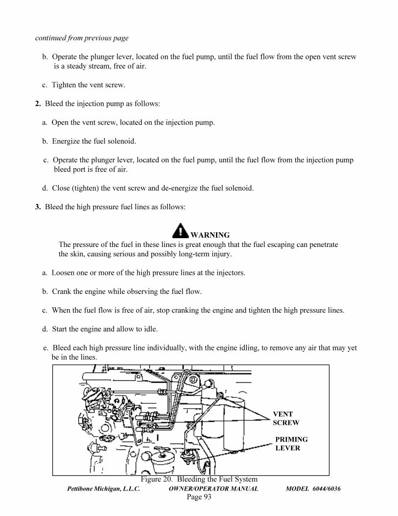
Page 93Pettibone Michigan, L.L.C. OWNER/OPERATOR MANUAL MODEL 6044/6036
continued from previous page
b. Operate the plunger lever, located on the fuel pump, until the fuel flow from the open vent screwis a steady stream, free of air.
c. Tighten the vent screw.
2. Bleed the injection pump as follows:
a. Open the vent screw, located on the injection pump.
b. Energize the fuel solenoid.
c. Operate the plunger lever, located on the fuel pump, until the fuel flow from the injection pumpbleed port is free of air.
d. Close (tighten) the vent screw and de-energize the fuel solenoid.
3. Bleed the high pressure fuel lines as follows:
WARNINGThe pressure of the fuel in these lines is great enough that the fuel escaping can penetratethe skin, causing serious and possibly long-term injury.
a. Loosen one or more of the high pressure lines at the injectors.
b. Crank the engine while observing the fuel flow.
c. When the fuel flow is free of air, stop cranking the engine and tighten the high pressure lines.
d. Start the engine and allow to idle.
e. Bleed each high pressure line individually, with the engine idling, to remove any air that may yetbe in the lines.
Figure 20. Bleeding the Fuel System
VENTSCREW
PRIMINGLEVER
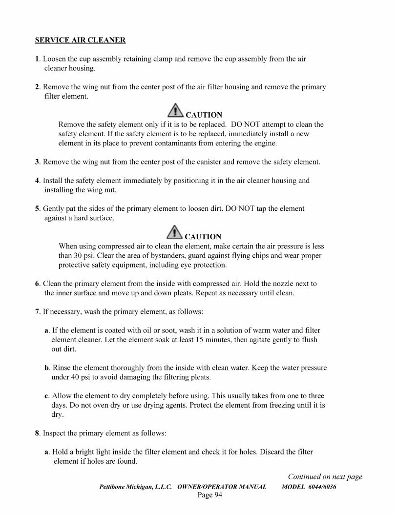
Page 94
TRAVERSE LIFT
Pettibone Michigan, L.L.C. OWNER/OPERATOR MANUAL MODEL 6044/6036
SERVICE AIR CLEANER
1. Loosen the cup assembly retaining clamp and remove the cup assembly from the aircleaner housing.
2. Remove the wing nut from the center post of the air filter housing and remove the primaryfilter element.
CAUTIONRemove the safety element only if it is to be replaced. DO NOT attempt to clean thesafety element. If the safety element is to be replaced, immediately install a newelement in its place to prevent contaminants from entering the engine.
3. Remove the wing nut from the center post of the canister and remove the safety element.
4. Install the safety element immediately by positioning it in the air cleaner housing andinstalling the wing nut.
5. Gently pat the sides of the primary element to loosen dirt. DO NOT tap the elementagainst a hard surface.
CAUTIONWhen using compressed air to clean the element, make certain the air pressure is lessthan 30 psi. Clear the area of bystanders, guard against flying chips and wear properprotective safety equipment, including eye protection.
6. Clean the primary element from the inside with compressed air. Hold the nozzle next tothe inner surface and move up and down pleats. Repeat as necessary until clean.
7. If necessary, wash the primary element, as follows:
a. If the element is coated with oil or soot, wash it in a solution of warm water and filterelement cleaner. Let the element soak at least 15 minutes, then agitate gently to flushout dirt.
b. Rinse the element thoroughly from the inside with clean water. Keep the water pressureunder 40 psi to avoid damaging the filtering pleats.
c. Allow the element to dry completely before using. This usually takes from one to threedays. Do not oven dry or use drying agents. Protect the element from freezing until it isdry.
8. Inspect the primary element as follows:
a. Hold a bright light inside the filter element and check it for holes. Discard the filterelement if holes are found.
Continued on next page
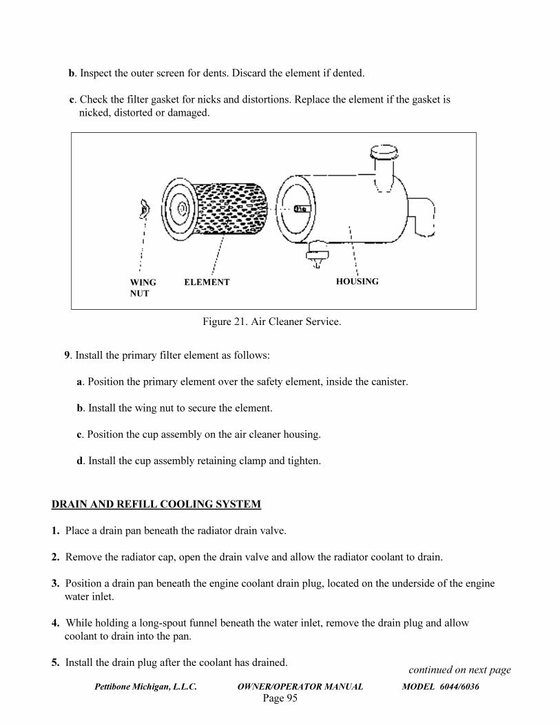
Page 95Pettibone Michigan, L.L.C. OWNER/OPERATOR MANUAL MODEL 6044/6036
b. Inspect the outer screen for dents. Discard the element if dented.
c. Check the filter gasket for nicks and distortions. Replace the element if the gasket isnicked, distorted or damaged.
DRAIN AND REFILL COOLING SYSTEM
1. Place a drain pan beneath the radiator drain valve.
2. Remove the radiator cap, open the drain valve and allow the radiator coolant to drain.
3. Position a drain pan beneath the engine coolant drain plug, located on the underside of the enginewater inlet.
4. While holding a long-spout funnel beneath the water inlet, remove the drain plug and allowcoolant to drain into the pan.
5. Install the drain plug after the coolant has drained.
9. Install the primary filter element as follows:
a. Position the primary element over the safety element, inside the canister.
b. Install the wing nut to secure the element.
c. Position the cup assembly on the air cleaner housing.
d. Install the cup assembly retaining clamp and tighten.
Figure 21. Air Cleaner Service.
WINGNUT
ELEMENT HOUSING
continued on next page
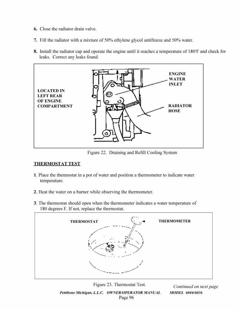
Page 96
TRAVERSE LIFT
Pettibone Michigan, L.L.C. OWNER/OPERATOR MANUAL MODEL 6044/6036
6. Close the radiator drain valve.
7. Fill the radiator with a mixture of 50% ethylene glycol antifreeze and 50% water.
8. Install the radiator cap and operate the engine until it reaches a temperature of 180oF and check forleaks. Correct any leaks found.
Figure 22. Draining and Refill Cooling System
THERMOSTAT TEST
1. Place the thermostat in a pot of water and position a thermometer to indicate water temperature.
2. Heat the water on a burner while observing the thermometer.
3. The thermostat should open when the thermometer indicates a water temperature of 180 degrees F. If not, replace the thermostat.
ENGINEWATERINLET
RADIATORHOSE
LOCATED INLEFT REAROF ENGINECOMPARTMENT
Continued on next pageFigure 23. Thermostat Test.
THERMOMETERTHERMOSTAT
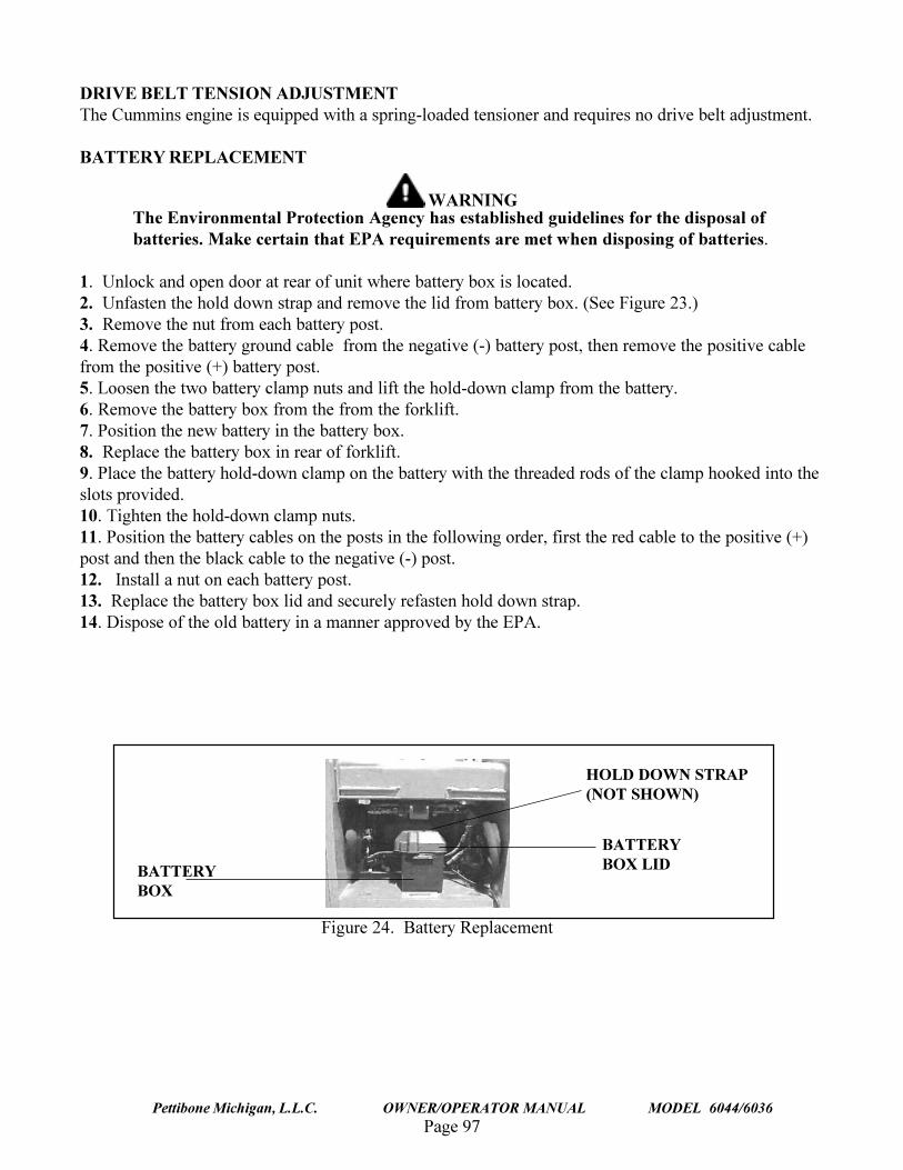
Page 97Pettibone Michigan, L.L.C. OWNER/OPERATOR MANUAL MODEL 6044/6036
DRIVE BELT TENSION ADJUSTMENTThe Cummins engine is equipped with a spring-loaded tensioner and requires no drive belt adjustment.
BATTERY REPLACEMENT
WARNINGThe Environmental Protection Agency has established guidelines for the disposal ofbatteries. Make certain that EPA requirements are met when disposing of batteries.
1. Unlock and open door at rear of unit where battery box is located.2. Unfasten the hold down strap and remove the lid from battery box. (See Figure 23.)3. Remove the nut from each battery post.4. Remove the battery ground cable from the negative (-) battery post, then remove the positive cablefrom the positive (+) battery post.5. Loosen the two battery clamp nuts and lift the hold-down clamp from the battery.6. Remove the battery box from the from the forklift.7. Position the new battery in the battery box.8. Replace the battery box in rear of forklift.9. Place the battery hold-down clamp on the battery with the threaded rods of the clamp hooked into theslots provided.10. Tighten the hold-down clamp nuts.11. Position the battery cables on the posts in the following order, first the red cable to the positive (+)post and then the black cable to the negative (-) post.12. Install a nut on each battery post.13. Replace the battery box lid and securely refasten hold down strap.14. Dispose of the old battery in a manner approved by the EPA.
BATTERYBOX
HOLD DOWN STRAP(NOT SHOWN)
BATTERYBOX LID
Figure 24. Battery Replacement
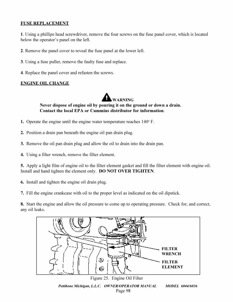
Page 98
TRAVERSE LIFT
Pettibone Michigan, L.L.C. OWNER/OPERATOR MANUAL MODEL 6044/6036
FUSE REPLACEMENT
1. Using a phillips head screwdriver, remove the four screws on the fuse panel cover, which is locatedbelow the operator�s panel on the left.
2. Remove the panel cover to reveal the fuse panel at the lower left.
3. Using a fuse puller, remove the faulty fuse and replace.
4. Replace the panel cover and refasten the screws.
ENGINE OIL CHANGE
WARNINGNever dispose of engine oil by pouring it on the ground or down a drain.Contact the local EPA or Cummins distributor for information.
1. Operate the engine until the engine water temperature reaches 140o F.
2. Position a drain pan beneath the engine oil pan drain plug.
3. Remove the oil pan drain plug and allow the oil to drain into the drain pan.
4. Using a filter wrench, remove the filter element.
5. Apply a light film of engine oil to the filter element gasket and fill the filter element with engine oil.Install and hand tighten the element only. DO NOT OVER TIGHTEN.
6. Install and tighten the engine oil drain plug.
7. Fill the engine crankcase with oil to the proper level as indicated on the oil dipstick.
8. Start the engine and allow the oil pressure to come up to operating pressure. Check for, and correct,any oil leaks.
FILTERWRENCH
FILTERELEMENT
Figure 25. Engine Oil Filter
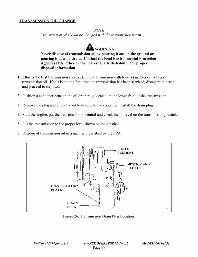
Page 99Pettibone Michigan, L.L.C. OWNER/OPERATOR MANUAL MODEL 6044/6036
TRANSMISSION OIL CHANGE
NOTETransmission oil should be changed with the transmission warm.
WARNINGNever dispose of transmission oil by pouring it out on the ground orpouring it down a drain. Contact the local Environmental ProtectionAgency (EPA) office or the nearest Clark Distributor for properdisposal information.
1. If this is the first transmission service, fill the transmission with four (4) gallons of C-3 typetransmission oil. If this is not the first time the transmission has been serviced, disregard this stepand proceed to step two.
2. Position a container beneath the oil drain plug located on the lower front of the transmission.
3. Remove the plug and allow the oil to drain into the container. Install the drain plug.
4. Start the engine, put the transmission in neutral and check the oil level on the transmission joystick.
5. Fill the transmission to the proper level shown on the dipstick.
6. Dispose of transmission oil in a manner prescribed by the EPA.
DRAINPLUG
IDENTIFICATIONPLATE
DIPSTICK ANDFILL TUBE
FILTERELEMENT
Figure 26. Transmission Drain Plug Location.
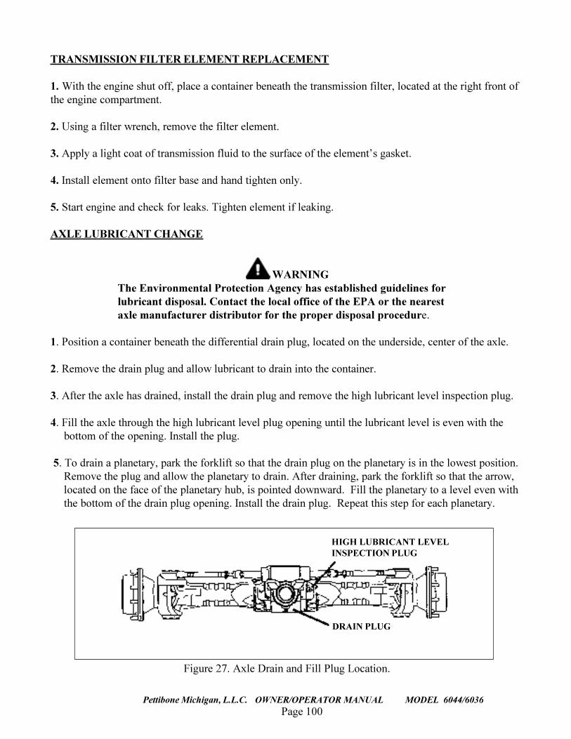
Page 100
TRAVERSE LIFT
Pettibone Michigan, L.L.C. OWNER/OPERATOR MANUAL MODEL 6044/6036
TRANSMISSION FILTER ELEMENT REPLACEMENT
1. With the engine shut off, place a container beneath the transmission filter, located at the right front ofthe engine compartment.
2. Using a filter wrench, remove the filter element.
3. Apply a light coat of transmission fluid to the surface of the element�s gasket.
4. Install element onto filter base and hand tighten only.
5. Start engine and check for leaks. Tighten element if leaking.
AXLE LUBRICANT CHANGE
WARNINGThe Environmental Protection Agency has established guidelines forlubricant disposal. Contact the local office of the EPA or the nearestaxle manufacturer distributor for the proper disposal procedure.
1. Position a container beneath the differential drain plug, located on the underside, center of the axle.
2. Remove the drain plug and allow lubricant to drain into the container.
3. After the axle has drained, install the drain plug and remove the high lubricant level inspection plug.
4. Fill the axle through the high lubricant level plug opening until the lubricant level is even with thebottom of the opening. Install the plug.
5. To drain a planetary, park the forklift so that the drain plug on the planetary is in the lowest position.Remove the plug and allow the planetary to drain. After draining, park the forklift so that the arrow,located on the face of the planetary hub, is pointed downward. Fill the planetary to a level even withthe bottom of the drain plug opening. Install the drain plug. Repeat this step for each planetary.
HIGH LUBRICANT LEVELINSPECTION PLUG
DRAIN PLUG
Figure 27. Axle Drain and Fill Plug Location.
Page 101Pettibone Michigan, L.L.C. OWNER/OPERATOR MANUAL MODEL 6044/6036
SUMMARY
This manual has been furnished by Pettibone Michigan L.L.C. to be used as a guide for equipmentoperation and routine maintenance. Remember, this machine can be extremely dangerous when operatedrecklessly. The most important safety feature of a Pettibone machine is the operator.
The 6044 is designed to encourage daily, routine maintenance by locating maintenance points in easilyaccessible locations. Constant adherence to the maintenance schedules listed herein will serve tolengthen the usable life of this machine. Should a problem arise which you cannot resolve, contact yourservicing dealer immediately, or call us at (906) 353-6611; we�re here to ensure your satisfaction withPettibone Michigan products.
THANK YOU FOR CHOOSING PETTIBONE


![Presentatian kpt 6044 [compatibility mode]](https://static.fdocuments.net/doc/165x107/5497c594b47959604d8b52e9/presentatian-kpt-6044-compatibility-mode.jpg)