603 Safety Light Curtain Type 2 SF2B SERIES Ver - PSD API
28
603 Related Information FIBER SENSORS LASER SENSORS PHOTOELECTRIC SENSORS MICRO PHOTOELECTRIC SENSORS AREA SENSORS SAFETY LIGHT CURTAINS / SAFETY COMPONENTS PRESSURE / FLOW SENSORS INDUCTIVE PROXIMITY SENSORS PARTICULAR USE SENSORS SENSOR OPTIONS SIMPLE WIRE-SAVING UNITS WIRE-SAVING SYSTEMS MEASUREMENT SENSORS STATIC CONTROL DEVICES LASER MARKERS PLC HUMAN MACHINE INTERFACES ENERGY MANAGEMENT SOLUTIONS FA COMPONENTS MACHINE VISION SYSTEMS UV CURING SYSTEMS Selection Guide Safety Light Curtains Safety Control Units Safety Components SF4D SF4B/ SF4B-G SF4B-C SF4C BSF4-AH80 SF2B SF2C Definition of Sensing Heights SF2B SERIES Ver.2 Type 2 safety solution International regulations for safety measures at reasonable cost Listing Conforming to OSHA / ANSI Extensive range of variations available with sensing widths from 168 mm to 1,912 mm 6.614 in to 75.275 in Protective structure IP67* is achieved with a seamless structure that has reduced seams *Version 2.0 or later Two types are available for different minimum sensing object sizes. The inner unit is protected by a cylindrical inner case. The seams of unit and lens surfaces have been greatly reduced, so that particles of oil mists and dust are prevented from getting in. Hand protection type SF2B-H□ Minimum sensing object ø27 mm ø1.063 in 20 mm 0.787 in beam pitch Arm / Foot protection type SF2B-A□ Minimum sensing object ø47 mm ø1.850 in 40 mm 1.575 in beam pitch Safety Light Curtain Type 2 ■ General terms and conditions ............. F-3 ■ Selection guide .............................. P.457~ ■ SF-C11/C13 .....................................P.663~ ■ SF-C21 ............................................. P.647~ Certified The photograph shows a cut-away model. Inner case Inner case Protective case End unit Internal unit Upgrade Guide Upgraded to version 2.0 from January 2009 shipments. Protection Conventional: IP65 (IEC) <Previous> Ver.2: IP65 / IP67 (IEC, JIS) <New> panasonic.net/id/pidsx/global Category 2 PLc SIL1 The control category differs depending on the configuration and wiring of the external circuit. Glossary of terms ....................... P.1549~ General precautions ..................... P.1595
Transcript of 603 Safety Light Curtain Type 2 SF2B SERIES Ver - PSD API

603
Related InformationFIBER
SENSORS
LASERSENSORS
PHOTOELECTRICSENSORS
MICROPHOTOELECTRIC
SENSORS
AREASENSORS
SAFETY LIGHT CURTAINS /
SAFETY COMPONENTSPRESSURE /
FLOWSENSORS
INDUCTIVEPROXIMITY
SENSORS
PARTICULARUSE SENSORS
SENSOROPTIONS
SIMPLEWIRE-SAVING
UNITS
WIRE-SAVING SYSTEMS
MEASUREMENTSENSORS
STATIC CONTROL DEVICES
LASERMARKERS
PLC
HUMAN MACHINE INTERFACES
ENERGY MANAGEMENT
SOLUTIONS
FA COMPONENTS
MACHINE VISION SYSTEMS
UV CURING SYSTEMS
Selection Guide
Safety Light Curtains
Safety Control Units
Safety Components
SF4DSF4B/
SF4B-GSF4B-C
SF4C
BSF4-AH80
SF2B
SF2CDefinition of
Sensing Heights
SF2B SERIES Ver.2
Type 2 safety solutionInternational regulations for safety measures at reasonable cost
Listing
Conforming toOSHA / ANSI
Extensive range of variations available with sensing widths from 168 mm to 1,912 mm 6.614 in to 75.275 in
Protective structure IP67* is achieved with a seamless structure that has reduced seams *Version 2.0 or later
Two types are available for different minimum sensing object sizes.
The inner unit is protected by a cylindrical inner case. The seams of unit and lens surfaces have been greatly reduced, so that particles of oil mists and dust are prevented from getting in.
Hand protection type SF2B-H
Minimum sensing object ø27 mm ø1.063 in
20 mm 0.787 in beam pitch
Arm / Foot protection type SF2B-A
Minimum sensing object ø47 mm ø1.850 in
40 mm 1.575 in beam pitch
Safety Light Curtain Type 2
General terms and conditions ............. F-3 Selection guide ..............................P.457~
SF-C11/C13 .....................................P.663~ SF-C21 ............................................. P.647~
Certified
Certified* (Excluding SF4B--03<V2>)(SF4B--03<V2>only)Conforming to 4584
Conforming toOSHA/ANSIApproved ListingConforming to Machine
& EMC Directive
The photograph shows a cut-away model.
Inner caseInner case
Protective case
End unit
Internal unit
Upgrade Guide
Upgraded to version 2.0 from January 2009 shipments.Protection
Conventional: IP65 (IEC) <Previous>
Ver.2: IP65 / IP67 (IEC, JIS) <New>
panasonic.net/id/pidsx/globalCategory 2 PLc SIL1
The control category differs depending on the configuration and wiring of the external circuit.
Glossary of terms ....................... P.1549~ General precautions ..................... P.1595

Safety Light Curtain Type 2 SF2B SERIES Ver.2 604
FIBERSENSORS
LASERSENSORS
PHOTOELECTRICSENSORS
MICROPHOTOELECTRICSENSORS
AREASENSORS
SAFETY LIGHT CURTAINS /SAFETY COMPONENTSPRESSURE / FLOWSENSORSINDUCTIVEPROXIMITYSENSORS
PARTICULARUSE SENSORS
SENSOROPTIONS
SIMPLEWIRE-SAVINGUNITS
WIRE-SAVING SYSTEMS
MEASUREMENTSENSORS
STATIC CONTROL DEVICES
LASERMARKERS
PLC
HUMAN MACHINE INTERFACES
ENERGY MANAGEMENT SOLUTIONS
FA COMPONENTS
MACHINE VISION SYSTEMS
UV CURING SYSTEMS
Selection GuideSafety Light CurtainsSafety Control UnitsSafety Components
SF4DSF4B/SF4B-GSF4B-C
SF4C
BSF4-AH80
SF2B
SF2CDefinition of Sensing Heights
“ZERO” dead zone. Unit length = protective height, so mounting is possible with no dead zoneThe sensing area contains no dead spaces. Even with series connections, there are no dangerous openings at the interfaces between safety light curtains. This makes a simpler and more compact installation possible.
Previous model
“ZERO” dead zone when using series mounting
Dead zone
Gaps occurred at connecting pointIt used to be necessary to install a cover or offset the safety light curtain in order to eliminate gaps.
Dead zone when using series mounting
“ZERO” dead zone when using L-shaped mounting
Overlapped mounting
Complex installation Increased design and installation man-hours
Overlapped mounting when using L-shaped mounting
Mutual interference is reduced without need for interference prevention lines
Reducing the number of malfunctions caused by extraneous light
The scan timing of the safety light curtain is automatically shifted in order to reduce mutual interference.
A double scanning method and retry processing are new functions exclusive to that are effective in eliminating the effect of momentary extraneous light from peripheral equipment.
Irregularreflected light
Extraneous light (Obstacle detecting sensor)Extraneous light (Obstacle detecting sensor)
Extraneous light (flasher)Extraneous light (flasher)
SF2BSF2B SF2BSF2B
Note: The SF2B-H8- and SF2B-A4- cannot connected in series. For details, refer to “PRECAUTIONS FOR PROPER USE” (p.620~).
Series connection of up to three sets is possibleSub-sensors for series connection (optional) can be used to connect up to three sets of safety light curtains (up to a total of 128 beam channels maximum; however, the SF2B-A allows up to 96 beam channels when two sets are connected, and up to 64 beam channels when three sets are connected).
• The safety light curtains and the sub-sensors for serial connection (optional) have different models. When connecting safety light curtains in series, be sure to use the sub-sensors for serial connection and serial connection cables which are sold separately.
• The SF2B-H8- and SF2B-A4- cannot be connected in series. For details, refer to “Series connection” of “PRECAUTIONS FOR PROPER USE” (p.620~).
Safety light curtainSF2B-
Sub-sensor for seriesconnection onlySF2B-SL (Optional)
Sub-sensor for series connection only SF2B-SL (Optional)
Cables for series connection SF2B-CSL (Optional)
Hand protection type
Arm / Foot protection type
Hand protection type
Arm / Foot protection type
Hand protection type and Arm / Foot protection type can be used together.
SF2B
New concept

605 Safety Light Curtain Type 2 SF2B SERIES Ver.2
FIBERSENSORS
LASERSENSORS
PHOTOELECTRICSENSORS
MICROPHOTOELECTRIC
SENSORS
AREASENSORS
SAFETY LIGHT CURTAINS /
SAFETY COMPONENTSPRESSURE /
FLOWSENSORS
INDUCTIVEPROXIMITY
SENSORS
PARTICULARUSE SENSORS
SENSOROPTIONS
SIMPLEWIRE-SAVING
UNITS
WIRE-SAVING SYSTEMS
MEASUREMENTSENSORS
STATIC CONTROL DEVICES
LASERMARKERS
PLC
HUMAN MACHINE INTERFACES
ENERGY MANAGEMENT
SOLUTIONS
FA COMPONENTS
MACHINE VISION SYSTEMS
UV CURING SYSTEMS
Selection Guide
Safety Light Curtains
Safety Control Units
Safety Components
SF4DSF4B/
SF4B-GSF4B-C
SF4C
BSF4-AH80
SF2B
SF2CDefinition of
Sensing Heights
Equipped with a digital error indicator so that error details can be understood at a glance
Beam-axis alignment indicators show the incident light position at a glance
The system constantly checks the safety light curtain for problems such as incorrect cable wiring, disconnection, short-circuits, internal circuit problems, and incoming light problems.If a problem should occur, details of the error appear on the digital display. Therefore, smooth support is possible if problems occur at startup and during maintenance operations, even if assistance is given via telephone.
Beam-axis alignment indicators display the beam channels of the safety light curtain in four blocks.The blocks where the beam axes match will light up in red in turn. When all the beam axes receive light, all the LEDs light up green. Furthermore, a stability indicator (STB.) lights up when there is sufficient incoming light.
Breaking out error Normal operation
Digital error indicator
A
B
C
D
Beam-axis alignment indicator
Beam-axis alignment indicator
* When using the SF2B-CB05-B adapter cable,the beam axis alignment indicator of emitter cannot be used.
Adapter cables and adapter mounting brackets are available so that previous peripheral devices for safety light curtains can still be usedThe safety light curtain SF2-A / SF2-N series (discontinued model), area sensor NA40 series, and SF1-N series (discontinued model) can be replaced with the SF2B series using the current mounting holes and connection cables.
Selectable safety circuits
Significant cost reduction is achieved by using corner mirror
The safety light curtain unit has a built-in monitoring function for external devices (such as fused relay monitoring). This supports the construction of safety light curtain peripheral safety circuits which do not use a safety relay unit, and contributes to reduced costs and a more compact control panel. In addition, a connectable control unit is used, so that a safety circuit that is easy to construct and easy to install can be selected.
By using a single corner mirror, safety light curtain and peripheral safety circuit for one set are eliminated. Enables significant cost reduction and savings on wiring. The control category is unchanged.
Reset input
Utilizing connectable control unit
Redu
ced
com
pone
nt co
sts
Less
pro
cess
ing
Utilizing safety light curtainfunctions
SF2B series
SF2B series
Monitor
Monitor
Safety relay, etc.Contactor, etc.
Contactor, etc.
Uses external device monitoring function Motor, etc.
Motor, etc.Uses SF-C11
connectable control unit
Note: Construct a separate reset input circuit.
•Recommended safety relays
Panasonic Corporation Model No.: SF relay, slim type
SF relay, slim typeSFS3-L-DC24V (AG1S132)SFS4-L-DC24V (AG1S142)DIN terminal blockSFS4-SFD (AG1S847) [4-poles type]SFS6-SFD (AG1S867) [6-poles type]
SF relay, slim type
DIN terminal block
When setting up the safety light curtains in the L-shape or U-shape, usually two or three sets of the safety light curtains are required. However, using the corner mirror to reflect the laser light allows only one set of the safety light curtains to be set up at the L-shape or U-shape.
Corner mirrorRF-SFBH-
Note: Contact the manufacturers for details on the recommended products.
Safety Light Curtain Type 2 SF2B SERIES Ver.2 606
FIBERSENSORS
LASERSENSORS
PHOTO-ELECTRICSENSORSMICROPHOTO-ELECTRICSENSORS
AREASENSORS
SAFETY LIGHT CURTAINS /SAFETY COMPONENTSPRESSURE / FLOWSENSORS
INDUCTIVEPROXIMITYSENSORS
PARTICULARUSE SENSORS
SENSOROPTIONS
SIMPLEWIRE-SAVINGUNITS
WIRE-SAVING SYSTEMS
MEASURE-MENTSENSORS
STATIC CONTROL DEVICES
LASERMARKERS
PLC
HUMAN MACHINE INTERFACES
ENERGY MANAGEMENT SOLUTIONS
FA COMPONENTS
MACHINE VISION SYSTEMS
UV CURING SYSTEMS
Selection GuideSafety Light CurtainsSafety Control UnitsSafety Components
SF4DSF4B/SF4B-GSF4B-C
SF4C
BSF4-AH80
SF2B
SF2CDefinition of Sensing Heights
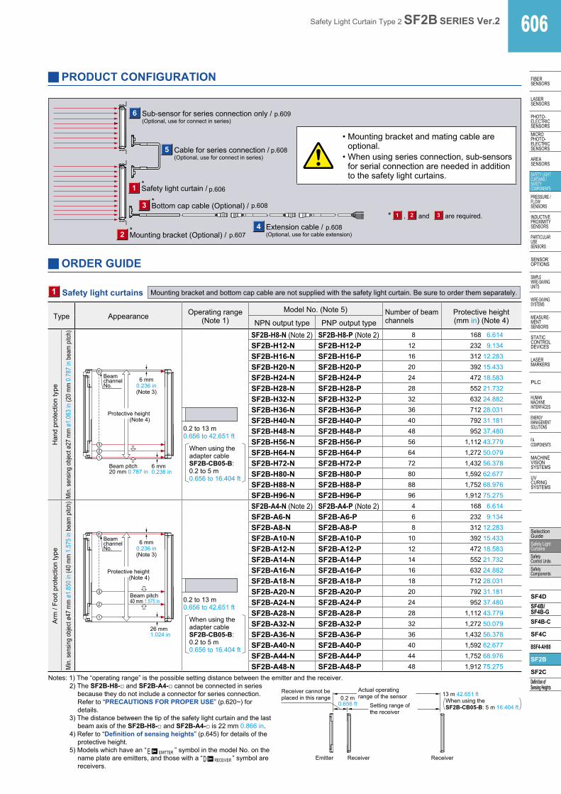
1 Safety light curtains Mounting bracket and bottom cap cable are not supplied with the safety light curtain. Be sure to order them separately.
Type Appearance Operating range (Note 1)
Model No. (Note 5) Number of beam channels
Protective height(mm in) (Note 4)NPN output type PNP output type
Han
d pr
otec
tion
type
Min.
sens
ing o
bject
ø27
mm
ø1.
063
in (2
0 m
m 0
.787
in b
eam
pitc
h)
Beam pitch 20 mm 0.787 in
Protective height(Note 4)
6 mm 0.236 in
6 mm0.236 in(Note 3)
Beam channel No.
0.2 to 13 m 0.656 to 42.651 ft
When using the adapter cable SF2B-CB05-B: 0.2 to 5 m0.656 to 16.404 ft
SF2B-H8-N (Note 2) SF2B-H8-P (Note 2) 8 168 6.614
SF2B-H12-N SF2B-H12-P 12 232 9.134
SF2B-H16-N SF2B-H16-P 16 312 12.283
SF2B-H20-N SF2B-H20-P 20 392 15.433
SF2B-H24-N SF2B-H24-P 24 472 18.583
SF2B-H28-N SF2B-H28-P 28 552 21.732
SF2B-H32-N SF2B-H32-P 32 632 24.882
SF2B-H36-N SF2B-H36-P 36 712 28.031
SF2B-H40-N SF2B-H40-P 40 792 31.181
SF2B-H48-N SF2B-H48-P 48 952 37.480
SF2B-H56-N SF2B-H56-P 56 1,112 43.779
SF2B-H64-N SF2B-H64-P 64 1,272 50.079
SF2B-H72-N SF2B-H72-P 72 1,432 56.378
SF2B-H80-N SF2B-H80-P 80 1,592 62.677
SF2B-H88-N SF2B-H88-P 88 1,752 68.976
SF2B-H96-N SF2B-H96-P 96 1,912 75.275
Arm
/ Fo
ot p
rote
ctio
n ty
pe
Min.
sens
ing o
bject
ø47
mm
ø1.
850
in (4
0 m
m 1
.575
in b
eam
pitc
h)
26 mm 1.024 in
6 mm 0.236 in (Note 3)
Beam channel No.
Beam pitch 40 mm 1.575 in
Protective height(Note 4)
0.2 to 13 m 0.656 to 42.651 ft
When using the adapter cable SF2B-CB05-B: 0.2 to 5 m0.656 to 16.404 ft
SF2B-A4-N (Note 2) SF2B-A4-P (Note 2) 4 168 6.614
SF2B-A6-N SF2B-A6-P 6 232 9.134
SF2B-A8-N SF2B-A8-P 8 312 12.283
SF2B-A10-N SF2B-A10-P 10 392 15.433
SF2B-A12-N SF2B-A12-P 12 472 18.583
SF2B-A14-N SF2B-A14-P 14 552 21.732
SF2B-A16-N SF2B-A16-P 16 632 24.882
SF2B-A18-N SF2B-A18-P 18 712 28.031
SF2B-A20-N SF2B-A20-P 20 792 31.181
SF2B-A24-N SF2B-A24-P 24 952 37.480
SF2B-A28-N SF2B-A28-P 28 1,112 43.779
SF2B-A32-N SF2B-A32-P 32 1,272 50.079
SF2B-A36-N SF2B-A36-P 36 1,432 56.378
SF2B-A40-N SF2B-A40-P 40 1,592 62.677
SF2B-A44-N SF2B-A44-P 44 1,752 68.976
SF2B-A48-N SF2B-A48-P 48 1,912 75.275
Notes: 1) The “operating range” is the possible setting distance between the emitter and the receiver. 2) The SF2B-H8- and SF2B-A4- cannot be connected in series
because they do not include a connector for series connection. Refer to “PRECAUTIONS FOR PROPER USE” (p.620~) for details.
3) The distance between the tip of the safety light curtain and the last beam axis of the SF2B-H8- and SF2B-A4- is 22 mm 0.866 in.
4) Refer to “Definition of sensing heights” (p.645) for details of the protective height.
5) Models which have an “
D RECEIVER
E EMITTER ” symbol in the model No. on the name plate are emitters, and those with a “D RECEIVER
E EMITTER
” symbol are receivers.
Receiver cannot beplaced in this range 0.2 m
0.656 ft
Emitter
Setting range ofthe receiver
Actual operatingrange of the sensor
Receiver Receiver
13 m 42.651 ft When using the SF2B-CB05-B: 5 m 16.404 ft
PRODUCT CONFIGURATION
6
5
1
2
3
4 1 2 3
Sub-sensor for series connection only / (Optional, use for connect in series)
Cable for series connection / (Optional, use for connect in series)
*Safety light curtain /
*Bottom cap cable (Optional) /
Extension cable / (Optional, use for cable extension)
* are required. and ,
*Mounting bracket (Optional) /
• Mounting bracket and mating cable are optional.
• When using series connection, sub-sensors for serial connection are needed in addition to the safety light curtains.
ORDER GUIDE
p.609
p.608
p.608
p.607p.608
p.606

607 Safety Light Curtain Type 2 SF2B SERIES Ver.2
FIBERSENSORS
LASERSENSORS
PHOTO-ELECTRICSENSORS
MICROPHOTO-
ELECTRICSENSORS
AREASENSORS
SAFETY LIGHT CURTAINS /
SAFETY COMPONENTSPRESSURE /
FLOWSENSORS
INDUCTIVEPROXIMITY
SENSORS
PARTICULARUSE
SENSORS
SENSOROPTIONS
SIMPLEWIRE-SAVING
UNITS
WIRE-SAVING SYSTEMS
MEASURE-MENT
SENSORS
STATIC CONTROL DEVICES
LASERMARKERS
PLC
HUMAN MACHINE
INTERFACES
ENERGY MANAGEMENT
SOLUTIONS
FA COMPONENTS
MACHINE VISION
SYSTEMS
UV CURING
SYSTEMS
Selection Guide
Safety Light Curtains
Safety Control Units
Safety Components
SF4DSF4B/
SF4B-GSF4B-C
SF4C
BSF4-AH80
SF2B
SF2CDefinition of
Sensing Heights
ORDER GUIDE
Designation Appearance Model No. Description
Standard mounting bracket
MS-SF2B-1
Used to mount the safety light curtain on the rear surface and side surface
4 pcs. per set for emitter and receiver
Dead zoneless mounting bracket
MS-SF2B-3
Mounting of the safety light curtain is possible so that the mounting bracket does not project past the protective height (safety light curtain length).
4 pcs. per set for emitter and receiver
Ada
pter
mou
ntin
g br
acke
ts
For SF2-A / SF2-N
For r
ear a
nd s
ide
mou
ntin
g
MS-SF2B-5
Used when replacing units in the SF2-A / SF2-N series. (discontinued model)
4 pcs. per set for emitter and receiver
For SF1-N / NA40
For r
ear m
ount
ing
MS-SF2B-4
Used when replacing units in theSF1-N (discontinued model) / NA40 series which are using the MS-SF1-1 / MS-NA40-1 sensor mounting brackets.(Note)
4 pcs. per set for emitter and receiver
For NA40
For s
ide
mou
ntin
g
MS-SF2B-6
Used when replacing units in the NA40 series which are side mounted (direct mounted).(Note)
4 pcs. per set for emitter and receiver
For SF1-N
For s
ide
mou
ntin
g
MS-SF2B-7
Used when replacing units in the SF1-N series (discontinued model) which are side mounted (discontinued model).
4 pcs. per set for emitter and receiver
2 Mounting brackets Mounting bracket is not supplied with the safety light curtain. Be sure to order it separately.
Safety light curtain
Hexagon-socket-head bolt [M3 (length 5 mm 0.197 in)]
Adapter mounting bracket MS-SF2B-6
Sensing surface
Accessory for MS-SF2B-6 ( )
Four bracket set Eight M3 (length 5 mm 0.197 in) hexagon-soket- head bolts are attached.
Safety light curtain
Adapter mounting bracket MS-SF2B-7
Adapter mounting bracket MS-SF2B-7
Sensing surface
Sensing surface
Accessory for MS-SF2B-7
Four bracket set Eight M3 (length 5 mm 0.197 in) hexagon-soket- head bolts are attached.
Hexagon-socket-head bolt [M3 (length 5 mm 0.197 in)]
Hexagon-socket-head bolt [M3 (length 5 mm 0.197 in)]
• MS-SF2B-7• MS-SF2B-6
Standard mounting bracket
Safety light curtain
Standard mounting bracket MS-SF2B-1
Sensing surface
Hexagon-socket-head bolts [M3 (length 5 mm 0.197 in)] Accessory for MS-SF2B-1 ( )
Four bracket setM3 (length 5 mm 0.197 in)hexagon-socket-head bolts areattached.
8 pcs. for safety light curtain mounting;8 pcs. for beam axis adjustment
• MS-SF2B-1
Safety light curtain
Adapter mounting brackets MS-SF2B-5
Hexagon-socket-head bolts [M3 (length 5 mm 0.197 in)]
Sensing surface
Accessory for MS-SF2B-5 ( )
Four bracket set M3 (length 5 mm 0.197 in)hexagon-socket-head bolts areattached.
8 pcs. for safety light curtain mounting;8 pcs. for beam axis adjustment
• MS-SF2B-5
Safety light curtain
Hexagon-socket-head bolt [M3 (length 5 mm 0.197 in)]
Adapter mounting bracket MS-SF2B-4
Sensing surface
Accessory for MS-SF2B-4 ( )
Four bracket set Eight M3 (length 5 mm0.197 in) hexagon-socket-head bolts are attached.
• MS-SF2B-4
• MS-SF2B-3
Safety light curtain
Sensing surface
Dead zoneless mounting bracket MS-SF2B-3
Four bracket set Six spacers for the intermediate supporting bracket and twelve M5 (length 8 mm 0.315 in) hexagon-socket-head bolts are attached.
Note: SF1-N-compatible mounting bracket can also be used for SF1-S / SF1-A series products that are discontinued. The NA40-compatible mounting bracket can also be used for NA40-S / NA40-B series products that are discontinued.

Safety Light Curtain Type 2 SF2B SERIES Ver.2 608
FIBERSENSORS
LASERSENSORS
PHOTO-ELECTRICSENSORSMICROPHOTO-ELECTRICSENSORS
AREASENSORS
SAFETY LIGHT CURTAINS /SAFETY COMPONENTSPRESSURE / FLOWSENSORS
INDUCTIVEPROXIMITYSENSORS
PARTICULARUSE SENSORS
SENSOROPTIONS
SIMPLEWIRE-SAVINGUNITS
WIRE-SAVING SYSTEMS
MEASURE-MENTSENSORS
STATIC CONTROL DEVICES
LASERMARKERS
PLC
HUMAN MACHINE INTERFACES
ENERGY MANAGEMENT SOLUTIONS
FA COMPONENTS
MACHINE VISION SYSTEMS
UV CURING SYSTEMS
Selection GuideSafety Light CurtainsSafety Control UnitsSafety Components
SF4DSF4B/SF4B-GSF4B-C
SF4C
BSF4-AH80
SF2B
SF2CDefinition of Sensing Heights
Type Appearance Model No. Description
8-co
re c
able
3 B
otto
m c
ap c
able
Dis
cret
e w
ire
SF2B-CCB3Cable length: 3 m 9.843 ftNet weight: 370 g approx. (2 cables)
Used for connecting to the safety light curtain and to other cables or the SF-C13 control unit.Two cables per set for emitter and receiverCable outer diameter: ø6 mm ø0.236 inCable color: Gray (for emitter)
Gray with black line (for receiver)The min. bending radius: R6 mm R0.236 in
SF2B-CCB7Cable length: 7 m 22.966 ftNet weight: 820 g approx. (2 cables)
SF2B-CCB10Cable length: 10 m 32.808 ftNet weight: 1,160 g approx. (2 cables)
SF2B-CCB15Cable length: 15 m 49.213 ftNet weight: 1,720 g approx. (2 cables)
Con
nect
or
SF2B-CB05 Cable length: 0.5 m 1.640 ftNet weight: 95 g approx. (2 cables)
Used for connecting to the safety light curtain and to an extension cable or the SF-C11 control unit.Two cables per set for emitter and receiverCable outer diameter: ø6 mm ø0.236 inConnector outer diameter: ø14 mm ø0.551 in max.Cable color: Gray (for emitter), Gray with black line (for receiver)Connector color: Gray (for emitter), Black (for receiver)The min. bending radius: R6 mm R0.236 in
SF2B-CB5 Cable length: 5 m 16.404 ftNet weight: 620 g approx. (2 cables)
SF2B-CB10 Cable length: 10 m 32.808 ftNet weight: 1,200 g approx. (2 cables)
4 E
xten
sion
cab
le
Dis
cret
e w
ire SFB-CC3 Cable length: 3 m 9.843 ftNet weight: 380 g approx. (2 cables)
Used for cable extension or connecting to the SF-C13 control unit.Two cables per set for emitter and receiverCable outer diameter: ø6 mm ø0.236 inConnector outer diameter: ø14 mm ø0.551 in max.Cable color: Gray (for emitter), Gray with black line (for receiver)The min. bending radius: R6 mm R0.236 in
SFB-CC10Cable length: 10 m 32.808 ftNet weight: 1,200 g approx. (2 cables)
With c
onnect
ors on
both e
nds
For e
mitte
r
SFB-CCJ10ECable length: 10 m 32.808 ftNet weight: 580 g approx. (1 cable)
Used for cable extension or connecting to the SF-C11 control unit.One each for emitter and receiverCable outer diameter: ø6 mm ø0.236 inConnector outer diameter: ø14 mm ø0.551 in max.Cable color: Gray (for emitter), Gray with black line (for receiver)Connector color: Gray (for emitter), Black (for receiver)The min. bending radius: R6 mm R0.236 inFo
r rece
iver
SFB-CCJ10DCable length: 10 m 32.808 ftNet weight: 600 g approx. (1 cable)
* 3
Ada
pter
cab
le (B
otto
m c
ap c
able
)
For S
F2-A
/ SF
2-N
SF2B-CB05-ACable length: 0.5 m 1.640 ftNet weight: 95 g approx. (2 cables)
Used when replacing units in the SF2-A / SF2-N series (discontinued model). The SF2N-CC cable with connector can be used without change, so that replacement with SF2B series units can be done smoothly.Two cables per set for emitter and receiverCable outer diameter: ø6 mm ø0.236 inConnector outer diameter: ø14 mm ø0.551 in max.Cable color: Gray (for emitter), Gray with black line (for receiver)Connector color: Gray (for emitter), Black (for receiver)The min. bending radius: R6 mm R0.236 in
4-co
re c
able
For S
F1-N
/ N
A40
SF2B-CB05-BCable length: 0.5 m 1.640 ftNet weight: 95 g approx. (2 cables)
Used when replacing units in the SF1-N (discontinued model) / NA40 series.The SF1-CC / NA40-CC cable with connector can be used without change, so that replacement with SF2B series units can be done smoothly.Two cables per set for emitter and receiverCable outer diameter: ø6 mm ø0.236 inConnector outer diameter: ø14 mm ø0.551 in max.Cable color: Gray (for emitter), Gray with black line (for receiver)Connector color: Gray (for emitter), Black (for receiver)The min. bending radius: R6 mm R0.236 in
* Please contact our office for wiring of adapter cables.
5 C
able
for
serie
sco
nnec
tion
* Used in conjunction with sub-sensor for serial connection only.
SF2B-CSL01Cable length: 0.1 m 0.328 ftNet weight: 70 g approx. (2 cables)
Use when connecting the sub-sensor for series connection to the safety light curtain in series.Two cables per set for emitter and receiver (common for emitter and receiver)Cable outer diameter: ø6 mm ø0.236 inCable color: Gray (common for emitter and receiver)The min. bending radius: R6 mm R0.236 in
SF2B-CSL05Cable length: 0.5 m 1.640 ftNet weight: 120 g approx. (2 cables)
3 4 5 Bottom cap cable / Extension cable / Cables for series connection Mating cable is not supplied with the safety light curtain. Be sure to order it separately.
• This function is used for replacing other safety light curtains or area sensors with these new units. The bottom cap cables and sensor mounting brackets used will vary depending on the models being replaced. Refer to the instruction manual for details on actual wiring and mounting.
Models being replaced Adapter cable Adapter mounting bracket Details of changes and points to note
SF2-A / SF2-N series(Discontinued product) SF2B-CB05-A MS-SF2B-5
• NPN output type: Connect the shielded wire to +V. PNP output type: Connect the shielded wire to 0 V.• Existing SF2N-CC connection cables (optional) can be used without change.• The interference prevention function (parallel connection) cannot be used.
SF1-N series(Discontinued product) SF2B-CB05-B
When using the MS-SF1-1: MS-SF2B-4
For direct mounting: MS-SF2B-7
• Emitter: Synchronization cable has changed to interference prevention cable.(Note 1)Receiver: Synchronization cable has changed to control output (OSSD 1).(Note 2)(Note 3)
• Existing SF1-CCA connection cables (optional) can be used without change.• The beam axis alignment indicator of emitter cannot be used.
NA40 series SF2B-CB05-BWhen using the MS-NA40-1:
MS-SF2B-4For direct mounting: MS-SF2B-6
• Control output (OSSD 2) is equipped instead of self-diagnosis output.(Note 3)• Emission halt function cannot be used.• Existing NA40-CC connection cables (optional) can be used without change.• The ambient temperature for the NA40-CC connection cables (optional) is
–10 to +50 °C +14 to +122 °F.
* Interchangeability function
ORDER GUIDE
Notes: 1) Not used in case of simple replacement of the SF1-N series (interference prevention wire is unused), therefore perform wire insulation so that it will not touch other wires.2) Not used in case of simple replacement of the SF1-N series (non-safety applications), therefore perform wire insulation so that it will not touch other wires.3) When used in safety applications, both OSSD1 and OSSD2 must be used.
609 Safety Light Curtain Type 2 SF2B SERIES Ver.2
FIBERSENSORS
LASERSENSORS
PHOTO-ELECTRICSENSORS
MICROPHOTO-
ELECTRICSENSORS
AREASENSORS
SAFETY LIGHT CURTAINS /
SAFETY COMPONENTSPRESSURE /
FLOWSENSORS
INDUCTIVEPROXIMITY
SENSORS
PARTICULARUSE
SENSORS
SENSOROPTIONS
SIMPLEWIRE-SAVING
UNITS
WIRE-SAVING SYSTEMS
MEASURE-MENT
SENSORS
STATIC CONTROL DEVICES
LASERMARKERS
PLC
HUMAN MACHINE
INTERFACES
ENERGY MANAGEMENT
SOLUTIONS
FA COMPONENTS
MACHINE VISION
SYSTEMS
UV CURING
SYSTEMS
Selection Guide
Safety Light Curtains
Safety Control Units
Safety Components
SF4DSF4B/
SF4B-GSF4B-C
SF4C
BSF4-AH80
SF2B
SF2CDefinition of
Sensing Heights
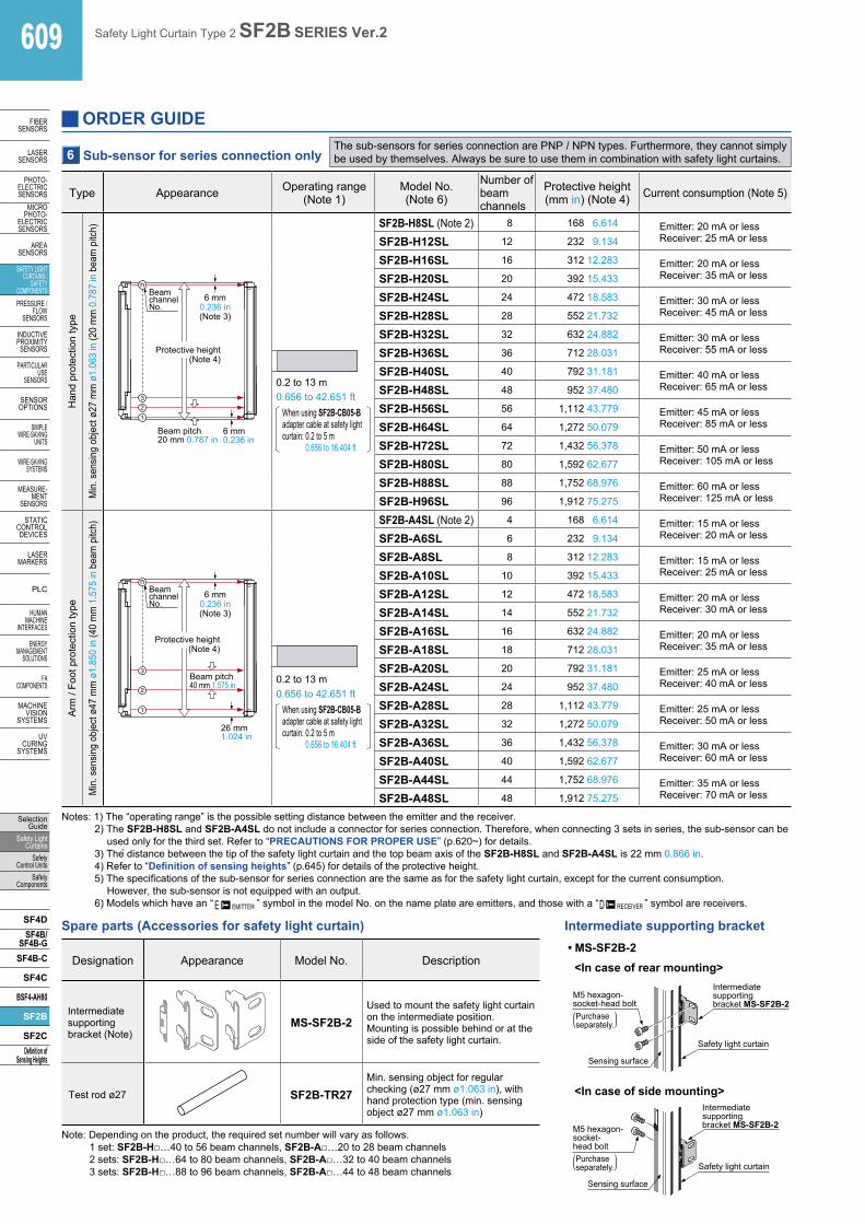
ORDER GUIDE
Type Appearance Operating range (Note 1)
Model No.(Note 6)
Number of beam channels
Protective height (mm in) (Note 4) Current consumption (Note 5)
Han
d pr
otec
tion
type
Min
. sen
sing
obje
ct ø
27 m
m ø
1.06
3 in
(20
mm
0.7
87 in
bea
m p
itch)
Beam pitch 20 mm 0.787 in
Protective height(Note 4)
6 mm 0.236 in
6 mm0.236 in(Note 3)
Beam channel No.
0.2 to 13 m0.656 to 42.651 ft
When using SF2B-CB05-B adapter cable at safety light curtain: 0.2 to 5 m
0.656 to 16.404 ft
SF2B-H8SL (Note 2) 8 168 6.614 Emitter: 20 mA or lessReceiver: 25 mA or lessSF2B-H12SL 12 232 9.134
SF2B-H16SL 16 312 12.283 Emitter: 20 mA or lessReceiver: 35 mA or lessSF2B-H20SL 20 392 15.433
SF2B-H24SL 24 472 18.583 Emitter: 30 mA or lessReceiver: 45 mA or lessSF2B-H28SL 28 552 21.732
SF2B-H32SL 32 632 24.882 Emitter: 30 mA or lessReceiver: 55 mA or lessSF2B-H36SL 36 712 28.031
SF2B-H40SL 40 792 31.181 Emitter: 40 mA or lessReceiver: 65 mA or lessSF2B-H48SL 48 952 37.480
SF2B-H56SL 56 1,112 43.779 Emitter: 45 mA or lessReceiver: 85 mA or lessSF2B-H64SL 64 1,272 50.079
SF2B-H72SL 72 1,432 56.378 Emitter: 50 mA or lessReceiver: 105 mA or lessSF2B-H80SL 80 1,592 62.677
SF2B-H88SL 88 1,752 68.976 Emitter: 60 mA or lessReceiver: 125 mA or lessSF2B-H96SL 96 1,912 75.275
Arm
/ Fo
ot p
rote
ctio
n ty
pe
Min
. sen
sing
obje
ct ø
47 m
m ø
1.85
0 in
(40
mm
1.5
75 in
bea
m p
itch)
26 mm 1.024 in
6 mm 0.236 in (Note 3)
Beam channel No.
Beam pitch 40 mm 1.575 in
Protective height(Note 4)
0.2 to 13 m0.656 to 42.651 ft
When using SF2B-CB05-B adapter cable at safety light curtain: 0.2 to 5 m
0.656 to 16.404 ft
SF2B-A4SL (Note 2) 4 168 6.614 Emitter: 15 mA or lessReceiver: 20 mA or lessSF2B-A6SL 6 232 9.134
SF2B-A8SL 8 312 12.283 Emitter: 15 mA or lessReceiver: 25 mA or lessSF2B-A10SL 10 392 15.433
SF2B-A12SL 12 472 18.583 Emitter: 20 mA or lessReceiver: 30 mA or lessSF2B-A14SL 14 552 21.732
SF2B-A16SL 16 632 24.882 Emitter: 20 mA or lessReceiver: 35 mA or lessSF2B-A18SL 18 712 28.031
SF2B-A20SL 20 792 31.181 Emitter: 25 mA or lessReceiver: 40 mA or lessSF2B-A24SL 24 952 37.480
SF2B-A28SL 28 1,112 43.779 Emitter: 25 mA or lessReceiver: 50 mA or lessSF2B-A32SL 32 1,272 50.079
SF2B-A36SL 36 1,432 56.378 Emitter: 30 mA or lessReceiver: 60 mA or lessSF2B-A40SL 40 1,592 62.677
SF2B-A44SL 44 1,752 68.976 Emitter: 35 mA or lessReceiver: 70 mA or lessSF2B-A48SL 48 1,912 75.275
6 Sub-sensor for series connection only The sub-sensors for series connection are PNP / NPN types. Furthermore, they cannot simply be used by themselves. Always be sure to use them in combination with safety light curtains.
Notes: 1) The “operating range” is the possible setting distance between the emitter and the receiver.2) The SF2B-H8SL and SF2B-A4SL do not include a connector for series connection. Therefore, when connecting 3 sets in series, the sub-sensor can be
used only for the third set. Refer to “PRECAUTIONS FOR PROPER USE” (p.620~) for details.3) The distance between the tip of the safety light curtain and the top beam axis of the SF2B-H8SL and SF2B-A4SL is 22 mm 0.866 in.4) Refer to “Definition of sensing heights” (p.645) for details of the protective height.5) The specifications of the sub-sensor for series connection are the same as for the safety light curtain, except for the current consumption.
However, the sub-sensor is not equipped with an output.6) Models which have an “
D RECEIVER
E EMITTER ” symbol in the model No. on the name plate are emitters, and those with a “D RECEIVER
E EMITTER
” symbol are receivers.
Designation Appearance Model No. Description
Intermediatesupportingbracket (Note)
MS-SF2B-2Used to mount the safety light curtain on the intermediate position. Mounting is possible behind or at the side of the safety light curtain.
Test rod ø27 SF2B-TR27Min. sensing object for regular checking (ø27 mm ø1.063 in), with hand protection type (min. sensing object ø27 mm ø1.063 in)
Note: Depending on the product, the required set number will vary as follows. 1 set: SF2B-H…40 to 56 beam channels, SF2B-A…20 to 28 beam channels 2 sets: SF2B-H…64 to 80 beam channels, SF2B-A…32 to 40 beam channels 3 sets: SF2B-H…88 to 96 beam channels, SF2B-A…44 to 48 beam channels
Spare parts (Accessories for safety light curtain)
M5 hexagon- socket-head bolt
Sensing surface
Intermediate supporting bracket MS-SF2B-2
Safety light curtain
Purchaseseparately.)(
Sensing surface
Safety light curtain
M5 hexagon- socket- head bolt Purchaseseparately.)(
Intermediate supporting bracket MS-SF2B-2
Intermediate supporting bracket• MS-SF2B-2
<In case of rear mounting>
<In case of side mounting>

Safety Light Curtain Type 2 SF2B SERIES Ver.2 610
FIBERSENSORS
LASERSENSORS
PHOTO-ELECTRICSENSORSMICROPHOTO-ELECTRICSENSORS
AREASENSORS
SAFETY LIGHT CURTAINS /SAFETY COMPONENTSPRESSURE / FLOWSENSORS
INDUCTIVEPROXIMITYSENSORS
PARTICULARUSE SENSORS
SENSOROPTIONS
SIMPLEWIRE-SAVINGUNITS
WIRE-SAVING SYSTEMS
MEASURE-MENTSENSORS
STATIC CONTROL DEVICES
LASERMARKERS
PLC
HUMAN MACHINE INTERFACES
ENERGY MANAGEMENT SOLUTIONS
FA COMPONENTS
MACHINE VISION SYSTEMS
UV CURING SYSTEMS
Selection GuideSafety Light CurtainsSafety Control UnitsSafety Components
SF4DSF4B/SF4B-GSF4B-C
SF4C
BSF4-AH80
SF2B
SF2CDefinition of Sensing Heights
Designation Appearance Model No. DescriptionApplicable cable
Connector connection type control unit
SF-C11 SF2B-CBSFB-CCJ10
Use 8-core cable with connector to connect to the safety light curtain.Compatible with up to Control Category 4 (Control Category 2 when used together with the SF2B series).
Slim type control unit SF-C13 SF2B-CCB
SFB-CC
Use a discrete wire cable to connect to the safety light curtain.Compatible with up to Control Category 4 (Control Category 2when used together with the SF2B series).
Control units
Note: Refer to SF-C10 series pages (p.663~) for the control units.
DesignationFront protection cover Corner mirrorApplicable
beam channels
Hand Arm / Foot Model No. Model No. Dimensions of effective reflective surface
8 4 FC-SF2BH-8 RF-SFBH-8 173 × 72 mm 6.811 × 2.835 in
12 6 FC-SF2BH-12 RF-SFBH-12 236 × 72 mm 9.291 × 2.835 in
16 8 FC-SF2BH-16 RF-SFBH-16 316 × 72 mm 12.441 × 2.835 in
20 10 FC-SF2BH-20 RF-SFBH-20 396 × 72 mm 15.591 × 2.835 in
24 12 FC-SF2BH-24 RF-SFBH-24 476 × 72 mm 18.740 × 2.835 in
28 14 FC-SF2BH-28 RF-SFBH-28 556 × 72 mm 21.890 × 2.835 in
32 16 FC-SF2BH-32 RF-SFBH-32 636 × 72 mm 25.039 × 2.835 in
36 18 FC-SF2BH-36 RF-SFBH-36 716 × 72 mm 28.190 × 2.835 in
40 20 FC-SF2BH-40 RF-SFBH-40 796 × 72 mm 31.339 × 2.835 in
48 24 FC-SF2BH-48 RF-SFBH-48 956 × 72 mm 37.638 × 2.835 in
56 28 FC-SF2BH-56 RF-SFBH-56 1,116 × 72 mm 43.937 × 2.835 in
64 32 FC-SF2BH-64 RF-SFBH-64 1,276 × 72 mm 50.236 × 2.835 in
72 36 FC-SF2BH-72 RF-SFBH-72 1,436 × 72 mm 56.535 × 2.835 in
80 40 FC-SF2BH-80 RF-SFBH-80 1,596 × 72 mm 62.835 × 2.835 in
88 44 FC-SF2BH-88 RF-SFBH-88 1,756 × 72 mm 69.134 × 2.835 in
96 48 FC-SF2BH-96 RF-SFBH-96 1,916 × 72 mm 75.433 × 2.835 in
Note: The model Nos. given above denote a single unit, not a pair of units. 2 units are required for use in mounting to the emitter / receiver. (Except for corner mirror)
Sensing range
Sensing range (Note)When using the SF2B-CB05-B
Only emitter installed
0.2 to 11.5 m0.656 to 37.730 ft
0.2 to 4.5 m0.656 to 14.764 ft
Only receiver installed
0.2 to 11.5 m0.656 to 37.730 ft
0.2 to 4.5 m0.656 to 14.764 ft
Both emitter and receiver installed
0.2 to 10.0 m0.656 to 32.808 ft
0.2 to 4.0 m0.656 to 13.123 ft
Note: The “operating range” is the possible setting distance between the emitter and the receiver.
OPTIONS
Front protection cover• FC-SF2BH-
This protects the sensing surfaces of the safety light curtain from flying objects such as welding spatter, oil and water.The operating range reduces when the front protection cover is used.Material: Polycarbonate
Front protectioncover
Corner mirror• RF-SFBH-
When setting up the safety light curtains in the L-shape or U-shape, usually two or three sets of the safety light curtains are required. However, using the corner mirror to reflect the laser light allows only one set of the safety light curtains to be set up at the L-shape or U-shape.
Type Corner mirrorItem Model No. RF-SFBH-
Sensing rangeWith one corner mirror: declined to 90 %, With two corner mirrors: declined to 80 %
(When used in combination with the SF2B series)En
viron
men
tal r
esist
ance Ambient temperature
–10 to +55 °C +14 to +131 °F (No dew condensation or icing allowed), Storage: –25 to +70 °C –13 to +158 °F
Ambient humidity 30 to 85 % RH, Storage: 30 to 95 % RH
Vibration resistance10 to 55 Hz frequency,
0.75 mm 2.953 in amplitude in X, Y and Z directions for two hours each
Shock resistance 300 m/s2 acceleration (30 G approx.) in X, Y and Z directions for three times each
MaterialEnclosure: Aluminum,
Mounting bracket: Stainless Steel,Mirror (rear surface mirror): Glass,
Side cover: EPDM
AccessoriesIntermediate supporting bracket: 1 set (RF-SFBH-40/48/56/64), 2 sets (RF-SFBH-72/80/88/96)
Note: Where measurement conditions have not been specified precisely, the conditions used were an ambient temperature of +20 °C +68 °F.
Specifications
Corner mirrorRF-SFBH-

611 Safety Light Curtain Type 2 SF2B SERIES Ver.2
FIBERSENSORS
LASERSENSORS
PHOTO-ELECTRICSENSORS
MICROPHOTO-
ELECTRICSENSORS
AREASENSORS
SAFETY LIGHT CURTAINS /
SAFETY COMPONENTSPRESSURE /
FLOWSENSORS
INDUCTIVEPROXIMITY
SENSORS
PARTICULARUSE
SENSORS
SENSOROPTIONS
SIMPLEWIRE-SAVING
UNITS
WIRE-SAVING SYSTEMS
MEASURE-MENT
SENSORS
STATIC CONTROL DEVICES
LASERMARKERS
PLC
HUMAN MACHINE
INTERFACES
ENERGY MANAGEMENT
SOLUTIONS
FA COMPONENTS
MACHINE VISION
SYSTEMS
UV CURING
SYSTEMS
Selection Guide
Safety Light Curtains
Safety Control Units
Safety Components
SF4DSF4B/
SF4B-GSF4B-C
SF4C
BSF4-AH80
SF2B
SF2CDefinition of
Sensing Heights
Designation Appearance Model No. Description
Test rod ø47 SF2B-TR47Min. sensing object for regular checking(ø47 mm ø1.850 in), with Arm / Foot protection type(min. sensing object ø47 mm ø1.850 in)
Laseralignmenttool
SF-LAT-2B
Allows easy beam axis alignment using easy-to-see laser beam
Specifications• Supply voltage: 3 V• Battery: 1.5 V (AA size battery) ×
2 pcs. (replaceable)• Battery lifetime: 30 hours approx. of continuous
operation (Manganese battery, at +25 °C +77 °F ambient temperature)
• Light source: Red semiconductor laser: class 2 (IEC / JIS / FDA) (Max. output: 1 mW, Peak emission wavelength: 650 nm 0.026 mil)
• Ambient temperature: 0 to +40 °C +32 to +104 °F(No dew condensation)
• Material: ABS (Enclosure) Aluminum (Mounting part:)
• Weight: Net weight: 150 g approx.(without batteries)
Large display unit for safety light curtain
SF-IND-2
With the auxiliary output of the safety light curtain, the operation is easily observable from various directions.
Specifications• Supply voltage: 24 V DC ±15 %• Current consumption: 12 mA or less• Indicators: Orange LED (8 pcs. used)
[Light up when external contact is ON]• Ambient temperature: –10 to +55 °C +14 to +131 °F
(No dew condensation or icing allowed)• Material: POM (Enclosure)
Polycarbonate (Cover) Cold rolled carbon steel (SPCC) (Bracket)
• Cable: 0.3 mm2 2-core cabtyre cable, 3 m 9.843 ft long• Net weight: 70 g approx. (including bracket)
I/O circuit diagrams<With NPN output type>
24 V DC±15 %
(Brown) +V
(Blue) –V
Internal circuit
or
Non-voltage contact or NPN open-collector transistor
Users’ circuit
Color code
+ –
*1
*1
or
24 V DC±15 %
(Brown) +V
(Blue) –V
Internal circuit
Non-voltage contact or PNP open-collector transistor
Users’ circuit
Color code
+ –
*1
*1
<With PNP output type>
Laser alignment tool• SF-LAT-2B
Large display unit for safety light curtain• SF-IND-2
(Purchase separately.)
Hexagon-socket- head bolt M5 (length 10 mm0.394 in or more)
OPTIONS
Attaches to top of safety light curtain.Tighten together the mounting bracket provided with the safety light curtain (MS-SF2B-1/4/5) and the mounting bracket of SF-IND-2.
Note: Contact Panasonic Corporation for details on the recommended products.
•Recommended safety relaysPanasonic Corporation SF relay, slim type
SF relay, slim typeSFS3-L-DC24V (AG1S132)SFS4-L-DC24V (AG1S142)
DIN terminal blockSFS4-SFD (AG1S847) [4-poles type] SFS6-SFD (AG1S867) [6-poles type]
(Note)
(Note) : LR6 dry cell batteries are not provided with the product. Please purchase them separately.

Safety Light Curtain Type 2 SF2B SERIES Ver.2 612
FIBERSENSORS
LASERSENSORS
PHOTO-ELECTRICSENSORSMICROPHOTO-ELECTRICSENSORS
AREASENSORS
SAFETY LIGHT CURTAINS /SAFETY COMPONENTSPRESSURE / FLOWSENSORS
INDUCTIVEPROXIMITYSENSORS
PARTICULARUSE SENSORS
SENSOROPTIONS
SIMPLEWIRE-SAVINGUNITS
WIRE-SAVING SYSTEMS
MEASURE-MENTSENSORS
STATIC CONTROL DEVICES
LASERMARKERS
PLC
HUMAN MACHINE INTERFACES
ENERGY MANAGEMENT SOLUTIONS
FA COMPONENTS
MACHINE VISION SYSTEMS
UV CURING SYSTEMS
Selection GuideSafety Light CurtainsSafety Control UnitsSafety Components
SF4DSF4B/SF4B-GSF4B-C
SF4C
BSF4-AH80
SF2B
SF2CDefinition of Sensing Heights
SPECIFICATIONS
Individual specifications
SF2B-H Hand protection type
Type Min. sensing object ø27 mm ø1.063 in type (20 mm 0.787 in beam pitch)
Mode
l No. NPN output SF2B-H8-N SF2B-H12-N SF2B-H16-N SF2B-H20-N SF2B-H24-N SF2B-H28-N
Item PNP output SF2B-H8-P SF2B-H12-P SF2B-H16-P SF2B-H20-P SF2B-H24-P SF2B-H28-PNumber of beam channels 8 12 16 20 24 28Beam pitch 20 mm 0.787 inProtective height 168 mm 6.614 in 232 mm 9.134 in 312 mm 12.283 in 392 mm 15.433 in 472 mm 18.583 in 552 mm 21.732 in
Current consumption Emitter: 40 mA or lessReceiver: 50 mA or less
Emitter: 40 mA or lessReceiver: 60 mA or less
Emitter: 50 mA or lessReceiver: 70 mA or less
PFHDNPN output 6.24 × 10⁻⁹ 6.44 × 10⁻⁹ 6.58 × 10⁻⁹ 6.77 × 10⁻⁹ 6.91 × 10⁻⁹ 7.10 × 10⁻⁹
PNP output 6.04 × 10⁻⁹ 6.23 × 10⁻⁹ 6.37 × 10⁻⁹ 6.57 × 10⁻⁹ 6.71 × 10⁻⁹ 6.90 × 10⁻⁹
MTTFD 100 years or more
Net weight (total of emitter and receiver) 170 g approx. 280 g approx. 400 g approx. 510 g approx. 610 g approx. 720 g approx.
Note: Where measurement conditions have not been specified precisely, the conditions used were an ambient temperature of +20 °C +68 °F. PFHD: Probability of dangerous failure per hour, MTTFD: Mean time to dangerous failure (in years)
Type Min. sensing object ø27 mm ø1.063 in type (20 mm 0.787 in beam pitch)
Mode
l No. NPN output SF2B-H72-N SF2B-H80-N SF2B-H88-N SF2B-H96-N
Item PNP output SF2B-H72-P SF2B-H80-P SF2B-H88-P SF2B-H96-PNumber of beam channels 72 80 88 96Beam pitch 20 mm 0.787 inProtective height 1,432 mm 56.378 in 1,592 mm 62.677 in 1,752 mm 68.976 in 1,912 mm 75.275 in
Current consumption Emitter: 70 mA or lessReceiver: 130 mA or less
Emitter: 80 mA or lessReceiver: 150 mA or less
PFHDNPN output 8.91 × 10⁻⁹ 9.24 × 10⁻⁹ 9.58 × 10⁻⁹ 9.91 × 10⁻⁹
PNP output 8.71 × 10⁻⁹ 9.04 × 10⁻⁹ 9.37 × 10⁻⁹ 9.71 × 10⁻⁹
MTTFD 100 years or more
Net weight (total of emitter and receiver) 1,900 g approx. 2,100 g approx. 2,300 g approx. 2,500 g approx.
Type Min. sensing object ø27 mm ø1.063 in type (20 mm 0.787 in beam pitch)
Mode
l No. NPN output SF2B-H32-N SF2B-H36-N SF2B-H40-N SF2B-H48-N SF2B-H56-N SF2B-H64-N
Item PNP output SF2B-H32-P SF2B-H36-P SF2B-H40-P SF2B-H48-P SF2B-H56-P SF2B-H64-PNumber of beam channels 32 36 40 48 56 64Beam pitch 20 mm 0.787 inProtective height 632 mm 24.882 in 712 mm 28.031 in 792 mm 31.181 in 952 mm 37.480 in 1,112 mm 43.779 in 1,272 mm 50.079 in
Current consumption Emitter: 50 mA or lessReceiver: 80 mA or less
Emitter: 60 mA or lessReceiver: 90 mA or less
Emitter: 65 mA or lessReceiver: 110 mA or less
PFHDNPN output 7.24 × 10⁻⁹ 7.44 × 10⁻⁹ 7.58 × 10⁻⁹ 7.91 × 10⁻⁹ 8.24 × 10⁻⁹ 8.58 × 10⁻⁹
PNP output 7.04 × 10⁻⁹ 7.23 × 10⁻⁹ 7.37 × 10⁻⁹ 7.71 × 10⁻⁹ 8.04 × 10⁻⁹ 8.37 × 10⁻⁹
MTTFD 100 years or more
Net weight (total of emitter and receiver) 830 g approx. 930 g approx. 1,000 g approx. 1,300 g approx. 1,500 g approx. 1,700 g approx.

613 Safety Light Curtain Type 2 SF2B SERIES Ver.2
FIBERSENSORS
LASERSENSORS
PHOTO-ELECTRICSENSORS
MICROPHOTO-
ELECTRICSENSORS
AREASENSORS
SAFETY LIGHT CURTAINS /
SAFETY COMPONENTSPRESSURE /
FLOWSENSORS
INDUCTIVEPROXIMITY
SENSORS
PARTICULARUSE
SENSORS
SENSOROPTIONS
SIMPLEWIRE-SAVING
UNITS
WIRE-SAVING SYSTEMS
MEASURE-MENT
SENSORS
STATIC CONTROL DEVICES
LASERMARKERS
PLC
HUMAN MACHINE
INTERFACES
ENERGY MANAGEMENT
SOLUTIONS
FA COMPONENTS
MACHINE VISION
SYSTEMS
UV CURING
SYSTEMS
Selection Guide
Safety Light Curtains
Safety Control Units
Safety Components
SF4DSF4B/
SF4B-GSF4B-C
SF4C
BSF4-AH80
SF2B
SF2CDefinition of
Sensing Heights
SF2B-A Arm / Foot protection type
Type Min. sensing object ø47 mm ø1.850 in type (40 mm 1.575 in beam pitch)
Mode
l No. NPN output SF2B-A4-N SF2B-A6-N SF2B-A8-N SF2B-A10-N SF2B-A12-N SF2B-A14-N
Item PNP output SF2B-A4-P SF2B-A6-P SF2B-A8-P SF2B-A10-P SF2B-A12-P SF2B-A14-PNumber of beam channels 4 6 8 10 12 14Beam pitch 40 mm 1.575 inProtective height 168 mm 6.614 in 232 mm 9.134 in 312 mm 12.283 in 392 mm 15.433 in 472 mm 18.583 in 552 mm 21.732 in
Current consumption Emitter: 35 mA or lessReceiver: 45 mA or less
Emitter: 35 mA or lessReceiver: 50 mA or less
Emitter: 40 mA or lessReceiver: 55 mA or less
PFHDNPN output 6.11 × 10⁻⁹ 6.23 × 10⁻⁹ 6.30 × 10⁻⁹ 6.42 × 10⁻⁹ 6.49 × 10⁻⁹ 6.62 × 10⁻⁹
PNP output 5.90 × 10⁻⁹ 6.03 × 10⁻⁹ 6.10 × 10⁻⁹ 6.22 × 10⁻⁹ 6.29 × 10⁻⁹ 6.41 × 10⁻⁹
MTTFD 100 years or more
Net weight (total of emitter and receiver) 170 g approx. 280 g approx. 400 g approx. 510 g approx. 610 g approx. 720 g approx.
Type Min. sensing object ø47 mm ø1.850 in type (40 mm 1.575 in beam pitch)
Mode
l No. NPN output SF2B-A16-N SF2B-A18-N SF2B-A20-N SF2B-A24-N SF2B-A28-N SF2B-A32-N
Item PNP output SF2B-A16-P SF2B-A18-P SF2B-A20-P SF2B-A24-P SF2B-A28-P SF2B-A32-PNumber of beam channels 16 18 20 24 28 32Beam pitch 40 mm 1.575 inProtective height 632 mm 24.882 in 712 mm 28.031 in 792 mm 31.181 in 952 mm 37.480 in 1,112 mm 43.779 in 1,272 mm 50.079 in
Current consumption Emitter: 40 mA or lessReceiver: 60 mA or less
Emitter: 45 mA or lessReceiver: 65 mA or less
Emitter: 50 mA or lessReceiver: 75 mA or less
PFHDNPN output 6.69 × 10⁻⁹ 6.81 × 10⁻⁹ 6.88 × 10⁻⁹ 7.08 × 10⁻⁹ 7.27 × 10⁻⁹ 7.46 × 10⁻⁹
PNP output 6.48 × 10⁻⁹ 6.61 × 10⁻⁹ 6.68 × 10⁻⁹ 6.87 × 10⁻⁹ 7.07 × 10⁻⁹ 7.26 × 10⁻⁹
MTTFD 100 years or more
Net weight (total of emitter and receiver) 830 g approx. 930 g approx. 1,000 g approx. 1,300 g approx. 1,500 g approx. 1,700 g approx.
Type Min. sensing object ø47 mm ø1.850 in type (40 mm 1.575 in beam pitch)
Mode
l No. NPN output SF2B-A36-N SF2B-A40-N SF2B-A44-N SF2B-A48-N
Item PNP output SF2B-A36-P SF2B-A40-P SF2B-A44-P SF2B-A48-PNumber of beam channels 36 40 44 48Beam pitch 40 mm 1.575 inProtective height 1,432 mm 56.378 in 1,592 mm 62.677 in 1,752 mm 68.976 in 1,912 mm 75.275 in
Current consumption Emitter: 55 mA or lessReceiver: 85 mA or less
Emitter: 60 mA or lessReceiver: 95 mA or less
PFHDNPN output 7.66 × 10⁻⁹ 7.85 × 10⁻⁹ 8.05 × 10⁻⁹ 8.24 × 10⁻⁹
PNP output 7.46 × 10⁻⁹ 7.65 × 10⁻⁹ 7.84 × 10⁻⁹ 8.04 × 10⁻⁹
MTTFD 100 years or more
Net weight (total of emitter and receiver) 1,900 g approx. 2,100 g approx. 2,300 g approx. 2,500 g approx.
Notes: Where measurement conditions have not been specified precisely, the conditions used were an ambient temperature of +20 °C +68 °F. PFHD: Probability of dangerous failure per hour, MTTFD: Mean time to dangerous failure (in years)
SPECIFICATIONS

Safety Light Curtain Type 2 SF2B SERIES Ver.2 614
FIBERSENSORS
LASERSENSORS
PHOTO-ELECTRICSENSORSMICROPHOTO-ELECTRICSENSORS
AREASENSORS
SAFETY LIGHT CURTAINS /SAFETY COMPONENTSPRESSURE / FLOWSENSORS
INDUCTIVEPROXIMITYSENSORS
PARTICULARUSE SENSORS
SENSOROPTIONS
SIMPLEWIRE-SAVINGUNITS
WIRE-SAVING SYSTEMS
MEASURE-MENTSENSORS
STATIC CONTROL DEVICES
LASERMARKERS
PLC
HUMAN MACHINE INTERFACES
ENERGY MANAGEMENT SOLUTIONS
FA COMPONENTS
MACHINE VISION SYSTEMS
UV CURING SYSTEMS
Selection GuideSafety Light CurtainsSafety Control UnitsSafety Components
SF4DSF4B/SF4B-GSF4B-C
SF4C
BSF4-AH80
SF2B
SF2CDefinition of Sensing Heights
SPECIFICATIONS
Common specifications
Item
TypeMin. sensing object ø27 mm ø1.063 in type (20 mm 0.787 in beam pitch) Min. sensing object ø47 mm ø1.850 in type (40 mm 1.575 in beam pitch)
NPN output PNP output NPN output PNP output
Model No. SF2B-H-N SF2B-H-P SF2B-A-N SF2B-A-P
Applica
ble stan
dards (
Note 2
)
International standard IEC 61496-1/2 (Type 2), ISO 13849-1 (Category 2, PLc), IEC 61508-1 to 7 (SIL1)Japan JIS B 9704-1/2 (Type 2), JIS B 9705-1 (Category 2), JIS C 0508 (SIL1)Europe (EU) EN 61496-1 (Type 2), EN 55011
North America UL 61496-1/2 (Type 2), UL 508, UL 1998 (Class 1), CSA C22.2 No.14, CSA C22.2 No.0.8, OSHA 1910.212 (Note 3), OSHA 1910.217 (C) (Note 3), ANSI B11.1 to B11.19, ANSI/RIA 15.06
CE marking directive compliance Machinery Directive, EMC Directive, RoHS DirectiveOperating range 0.2 to 13 m 0.656 to 42.651 ft (0.2 to 5 m 0.656 to 16.404 ft when using the SF2B-CB05-B adapter cable)Min. sensing object ø27 mm ø1.063 in opaque object ø47 mm ø1.850 in opaque objectEffective aperture angle ±5° or less [for an operating range exceeding 3 m 9.843 ft (conforming to IEC 61496-2 / UL 61496-2)]Supply voltage 24 V DC ±15 % Ripple P-P 10 % or less
Control outputs(OSSD 1, OSSD 2)
<NPN output type>NPN open-collector transistor
• Max. sink current: 200 mA• Applied voltage: same as supply voltage
[between the control outputs (OSSD 1, OSSD 2) and 0 V]• Residual voltage: 2.0 V or less (sink current 200 mA)
(when using 30.5 m 100.066 ft length cable)
<PNP output type>PNP open-collector transistor
• Max. source current: 200 mA• Applied voltage: same as supply voltage
[between the control outputs (OSSD 1, OSSD 2) and +V]• Residual voltage: 2.5 V or less (sink current 200 mA)
(when using 30.5 m 100.066 ft length cable)
Operation mode ON when all beam channels are received, OFF when one or more beam channels are interrupted(OFF also in case of any malfunction in the safety light curtain or the synchronization signal)
Protection circuit IncorporatedResponse time OFF response: 15 ms or less, ON response: 40 to 60 ms
Auxiliary output (Aux)(Note 4)
<NPN output type>NPN open-collector transistor
• Max. sink current: 60 mA• Applied voltage: same as supply voltage
[between the auxiliary output and 0 V]• Residual voltage: 2.0 V or less (sink current 60 mA)
(when using 30.5 m 100.066 ft length cable)
<PNP output type>PNP open-collector transistor
• Max. source current: 60 mA• Applied voltage: same as supply voltage
[between the auxiliary output and +V]• Residual voltage: 2.5 V or less (sink current 60 mA)
(when using 30.5 m 100.066 ft length cable)
Operation mode When using SF2B-CCB or SF2B-CB: OFF when OSSD ON, ON when OSSD OFFWhen using SF2B-CB05-A: ON during normal operation, OFF when there is a problem with emitter operation or emission is halted
Protection circuit IncorporatedSynchronization method Cable synchronization (optical synchronization when using SF2B-CB05-B)
Interference prevention function
Incorporated• Series connection: 3 sets max. (Total 128 beam channels). (However, SF2B-A allows up to a total of 96 beam channels when
two sets are connected, and up to 64 beam channels when three sets are connected). (Note 5)SF2B-H and SF2B-A can be used together. (Note 6)When using SF2B-CB05-B (optical synchronization):• Series connection: 3 sets max. (Total 128 beam channels). (However, SF2B-A allows up to a total of 96 beam channels
when two sets are connected, and up to 64 beam channels when three sets are connected). (Note 5)• Parallel connection: 2 sets max.• Series and parallel mixed connection: Series connection of 3 sets max. and parallel connection of 2 sets max. are
simultaneously possible.SF2B-H and SF2B-A can be used together. (Note 6)
Emission halt function IncorporatedExternal device monitoring function Incorporated
Envir
onm
enta
l res
istan
ce Degree of protection IP65 (IEC) (*IP67 is later than Ver.2)Ambient temperature /Ambient humidity
–10 to +55 °C +14 to +131 °F (No dew condensation or icing allowed), Storage: –25 to +70 °C –13 to +158 °F / 30 to 85 % RH, Storage: 30 to 95 % RH
Ambient illuminance Incandescent light: 3,500 ℓx or less at the light-receiving faceDielectric strength voltage /Insulation resistance
1,000 V AC for one min. between all supply terminals connected together and enclosure / 20 MΩ, or more, with 500 V DC megger between all supply terminals connected together and enclosure
Vibration resistance /Shock resistance
10 to 55 Hz frequency, 0.75 mm 0.030 in double amplitude in X, Y and Z directions for two hours each / 300 m/s2 acceleration (30 G approx.) in X, Y and Z directions three times each
Emitting element Infrared LED (Peak emission wavelength: 870 nm 0.034 mil)Cable extension Extension up to total 30.5 m 100.066 ft is possible for both emitter and receiver, with optional mating cables.Connecting method ConnectorMaterial Enclosure: Aluminum, Upper and lower edges : Die-cast zinc alloy, Inner case: Polycarbonate · Polyester resin, Cap: PBT
Accessories MS-SF2B-2 (Intermediate supporting bracket): (Note 7)SF2B-TR27 (Test rod): 1 No. MS-SF2B-2 (Intermediate supporting bracket): (Note 7)
Notes: 1) Where measurement conditions have not been specified precisely, the conditions used were an ambient temperature of +20 °C +68 °F.2) Due to revisions of safety light curtain standards (Electro-sensitive protective equipment), type 2 safety light curtains are limited to PLc and SIL1
regarding PL and SIL standards.3) Not compatible when using the bottom cap cable SF2B-CB05-A.4) When using auxiliary output (AUX), the compatible cable SF2B-CB05-B (sold separately) cannot be used.5) SF2B-H8- and SF2B-A4- cannot be connected in series. For more information, refer to ‘‘PRECAUTIONS FOR PROPER USE’’ (p.620~).6) When making series connection mixing SF2B-H and SF2B-A, calculate by doubling the number of optical axes only for SF2B-A, and make the total
number of optical axes fall below 128 axes. (e.g.) When making series connection with SF2B-H36 and SF2B-A44, the total number of optical axes will be 124 axes. The number of optical axes for
SF2B-H36 + (number of optical axes for SF2B-A44 × 2) = total number of optical axes. 36 optical axes + (44 optical axes × 2) = 124 optical axes.7) Intermediate supporting bracket MS-SF2B-2 is included with the following products. The number included varies as follows depending on the product.
1 set: SF2B-H…40 to 56 beam channels, SF2B-A…20 to 28 beam channels 2 sets: SF2B-H…64 to 80 beam channels, SF2B-A…32 to 40 beam channels 3 sets: SF2B-H…88 to 96 beam channels, SF2B-A…44 to 48 beam channels
Refer to p.667 for the specifications for the control unit.

615 Safety Light Curtain Type 2 SF2B SERIES Ver.2
FIBERSENSORS
LASERSENSORS
PHOTO-ELECTRICSENSORS
MICROPHOTO-
ELECTRICSENSORS
AREASENSORS
SAFETY LIGHT CURTAINS /
SAFETY COMPONENTSPRESSURE /
FLOWSENSORS
INDUCTIVEPROXIMITY
SENSORS
PARTICULARUSE
SENSORS
SENSOROPTIONS
SIMPLEWIRE-SAVING
UNITS
WIRE-SAVING SYSTEMS
MEASURE-MENT
SENSORS
STATIC CONTROL DEVICES
LASERMARKERS
PLC
HUMAN MACHINE
INTERFACES
ENERGY MANAGEMENT
SOLUTIONS
FA COMPONENTS
MACHINE VISION
SYSTEMS
UV CURING
SYSTEMS
Selection Guide
Safety Light Curtains
Safety Control Units
Safety Components
SF4DSF4B/
SF4B-GSF4B-C
SF4C
BSF4-AH80
SF2B
SF2CDefinition of
Sensing Heights
I/O CIRCUIT AND WIRING DIAGRAMS
NPN output type When using a SF2B-CCB or SF2B-CB bottom cap cable
I/O circuit diagram Wiring diagram<In case of setting the external device monitoring function to enabled> <In case of setting the external device monitoring function to enabled>
Sen
sor c
ircui
t S
enso
r circ
uit
(Shield) (Yellow-green / Black) Auxiliary output
(Brown) +V
(Brown) +V
(Pale purple) Not connected
(Orange) Synchronization +
(Orange / Black) Synchronization – (Orange) Synchronization +
(Black) OSSD 1 (White) OSSD 2
(Yellow-green) External device monitoring input (Blue) 0 V
(Orange / Black) Synchronization – Users’ circuit Internal circuit
Users’ circuit Internal circuit
(Pink) Test input (Blue) 0 V
Connector pin No. Color code of mating cable
K1
K1
K1: External device (Force-guided relay or magnet contactor)
Load
* S1
(Shield)
Load
60 mA max.
200 mA max. 200 mA max.
7 4
3 8 2 5 6
6 5 1 7 3
4 8 2
24 V DC±15 %
+
–
1
K1
Load
(Brown)
(Shield)
(Yellow-green / Black)
(Pink)
(Pale purple)
(Orange / Black) (Orange)
Color code of mating cable
Load * S1
(Blue)
(Orange / Black)
(Orange)
(Brown)
(Shield)
(White)
(Blue) (Yellow-green)
(Black)
K1
K1: External device (Force-guided relay or magnet contactor)
1 2
3
4
5 6 7
8
1 2
3
4
5 6 7
8
Cable color: Gray
Cable color: Gray with black line
24 V DC±15 %
+
–
Emitter
Receiver
Note: Unused wires must be insulated to ensure that they do not come into contact with wires already in use.
Note: Unused wires must be insulated to ensure that they do not come into contact with wires already in use.
Emitter
Receiver
<In case of setting the external device monitoring function to disabled>
Emitter
K1
Load
* S1
1 2
3
4
5 6 7
8
1 2
3
4
5 6 7
8
(Brown)
(Shield) (Yellow-green / Black)
(Pink)
(Pale purple)
(Orange / Black) (Orange)
Color code of mating cable
(Blue)
(Orange / Black)
(Orange)
(Brown)
(Shield)
(White)
(Blue) (Yellow-green)
(Black)
K1: External device (Force-guided relay or magnet contactor)
Cable color: Gray
Cable color: Gray with black line
24 V DC±15 %
+
–
Note: Unused wires must be insulated to ensure that they do not come into contact with wires already in use.
CAUTIONConstruct the interlock (reset input) circuit separately.
* S1
Switch S1• Test input
Open: Emission halt 0 to +1.5 V (source current 5 mA or less): Emission
CAUTIONConstruct the interlock (reset input) circuit separately.
* S1
Switch S1• Test input
Open: Emission halt 0 to +1.5 V (source current 5 mA or less): Emission
<In case of setting the external device monitoring function to disabled>• In order to disable the external device monitoring function,
connect the auxiliary output and external device monitoring input. At such times, do not connect a load to the auxiliary output.
24 V DC±15%
K1 Load
* S1
Sen
sor c
ircui
t S
enso
r circ
uit
(Shield) (Yellow-green / Black) Auxiliary output
(Brown) +V
(Brown) +V
(Pale purple) Not connected
(Orange) Synchronization +
(Orange / Black) Synchronization – (Orange) Synchronization +
(Black) OSSD 1 (White) OSSD 2
(Yellow-green) External device monitoring input (Blue) 0 V
(Orange / Black) Synchronization – Users’ circuit Internal circuit
Users’ circuit Internal circuit
(Pink) Test input (Blue) 0 V
Connector pin No. Color code of mating cable
K1: External device (Force-guided relay or magnet contactor)
(Shield)
200 mA max. 200 mA max.
7 4
1 3 8 2 5 6
6 5 1 7 3
4 8 2
+
–
Emitter
Note: Unused wires must be insulated to ensure that they do not come into contact with wires already in use.
Receiver
Receiver

Safety Light Curtain Type 2 SF2B SERIES Ver.2 616
FIBERSENSORS
LASERSENSORS
PHOTO-ELECTRICSENSORSMICROPHOTO-ELECTRICSENSORS
AREASENSORS
SAFETY LIGHT CURTAINS /SAFETY COMPONENTSPRESSURE / FLOWSENSORS
INDUCTIVEPROXIMITYSENSORS
PARTICULARUSE SENSORS
SENSOROPTIONS
SIMPLEWIRE-SAVINGUNITS
WIRE-SAVING SYSTEMS
MEASURE-MENTSENSORS
STATIC CONTROL DEVICES
LASERMARKERS
PLC
HUMAN MACHINE INTERFACES
ENERGY MANAGEMENT SOLUTIONS
FA COMPONENTS
MACHINE VISION SYSTEMS
UV CURING SYSTEMS
Selection GuideSafety Light CurtainsSafety Control UnitsSafety Components
SF4DSF4B/SF4B-GSF4B-C
SF4C
BSF4-AH80
SF2B
SF2CDefinition of Sensing Heights
I/O CIRCUIT AND WIRING DIAGRAMS
PNP output type When using a SF2B-CCB or SF2B-CB bottom cap cable
I/O circuit diagram Wiring diagram<In case of setting the external device monitoring function to enabled> <In case of setting the external device monitoring function to enabled>
K1
K1
* S1 60 mA max.
200 mA max. 200 mA max.
Sen
sor c
ircui
t S
enso
r circ
uit
(Pink) Test input (Yellow-green / Black) Auxiliary output
(Brown) +V
(Brown) +V
(Pale purple) Not connected
(Orange) Synchronization +
(Orange / Black) Synchronization – (Orange) Synchronization +
(Black) OSSD 1 (White) OSSD 2
(Yellow-green) External device monitoring input
(Blue) 0 V
(Orange / Black) Synchronization – Users’ circuit Internal circuit
Users’ circuit Internal circuit
(Shield) (Blue) 0 V
Connector pin No. Color code of mating cable
K1: External device (Force-guided relay or magnet contactor)
(Shield)
7 8 1 3
4
2 5 6
6 5 1 7 8
4 3 2
Load
Load
24 V DC±15 %
+
–
K1
* S1
K1
1 2
3
4
5 6 7
8
(Brown)
(Pink)
(Yellow-green / Black)
(Shield)
(Pale purple)
(Orange / Black) (Orange)
Color code of mating cable
(Blue)
(Orange / Black)
(Orange)
(Brown)
(Yellow-green)
(White)
(Blue) (Shield)
(Black)
K1: External device (Force-guided relay or magnet contactor)
Cable color: Gray
Cable color: Gray with black line
1 2
3
4
5 6 7
8
Load
Load
24 V DC±15 %
+
–
Emitter
Receiver
Note: Unused wires must be insulated to ensure that they do not come into contact with wires already in use.
Emitter
Receiver
<In case of setting the external device monitoring function to disabled>
Emitter
K1
Load
* S1
1 2
3
4
5 6 7
8
1 2
3
4
5 6 7
8
(Brown)
(Pink)
(Yellow-green / Black)
(Shield)
(Pale purple)
(Orange / Black) (Orange)
Color code of mating cable
(Blue)
(Orange / Black)
(Orange)
(Brown)
(Yellow-green)
(White)
(Blue) (Shield)
(Black)
K1: External device (Force-guided relay or magnet contactor)
Cable color: Gray
Cable color: Gray with black line
24 V DC±15 %
+
–
Note: Unused wires must be insulated to ensure that they do not come into contact with wires already in use.
CAUTIONConstruct the interlock (reset input) circuit separately.
* S1
Switch S1• Test input
Open: Emission halt Vs to Vs – 2.5 V (sink current 5 mA or less): Emission (Note 2)
CAUTIONConstruct the interlock (reset input) circuit separately.
* S1
Switch S1• Test input
Open: Emission halt Vs to Vs – 2.5 V (sink current 5 mA or less): Emission (Note 2)
<In case of setting the external device monitoring function to disabled>• In order to disable the external device monitoring function,
connect the auxiliary output and external device monitoring input. At such times, do not connect a load to the auxiliary output.
K1
* S1
200 mA max. 200 mA max.
Sen
sor c
ircui
t S
enso
r circ
uit
(Pink) Test input (Yellow-green / Black) Auxiliary output
(Brown) +V
(Brown) +V
(Pale purple) Not connected
(Orange) Synchronization +
(Orange / Black) Synchronization – (Orange) Synchronization +
(Black) OSSD 1 (White) OSSD 2
(Yellow-green) External device monitoring input
(Blue) 0 V
(Orange / Black) Synchronization – Users’ circuit Internal circuit
Users’ circuit Internal circuit
(Shield) (Blue) 0 V
Connector pin No. Color code of mating cable
K1: External device (Force-guided relay or magnet contactor)
(Shield) Load
7 8 1 3
4
2 5 6
6 5 1 7 8
4 3 2
24 V DC±15 %
+
–
Emitter
Receiver
Receiver
Notes: 1) Unused wires must be insulated to ensure that they do not come into contact with wires already in use.
2) Vs is the applying supply voltage.
Notes: 1) Unused wires must be insulated to ensure that they do not come into contact with wires already in use.
2) Vs is the applying supply voltage.

617 Safety Light Curtain Type 2 SF2B SERIES Ver.2
FIBERSENSORS
LASERSENSORS
PHOTO-ELECTRICSENSORS
MICROPHOTO-
ELECTRICSENSORS
AREASENSORS
SAFETY LIGHT CURTAINS /
SAFETY COMPONENTSPRESSURE /
FLOWSENSORS
INDUCTIVEPROXIMITY
SENSORS
PARTICULARUSE
SENSORS
SENSOROPTIONS
SIMPLEWIRE-SAVING
UNITS
WIRE-SAVING SYSTEMS
MEASURE-MENT
SENSORS
STATIC CONTROL DEVICES
LASERMARKERS
PLC
HUMAN MACHINE
INTERFACES
ENERGY MANAGEMENT
SOLUTIONS
FA COMPONENTS
MACHINE VISION
SYSTEMS
UV CURING
SYSTEMS
Selection Guide
Safety Light Curtains
Safety Control Units
Safety Components
SF4DSF4B/
SF4B-GSF4B-C
SF4C
BSF4-AH80
SF2B
SF2CDefinition of
Sensing Heights
SF-C11
I/O CIRCUIT AND WIRING DIAGRAMS
For NPN output (plus ground)
• Set the safety light curtain input polarity selection switch to the NPN side and ground the + side.
3 M
+24 V DC
F
A1
A2
0 V
F.G.
T2 T1
K1
K2
KB
KB
KA KA
N
14 24 34 42 L1 L2 L3
13 23 33 41 X1 X2 A B
AUX
L1
NPN PNP SF-C11 control circuit
Receiver side connector
Emitter side connector
Ui
OUT FAULT INTER_LOCK
FUSE1 FUSE2 RESET (Note 1, 2)
TEST (Note 3)
Safety light curtain input polarity selection switch
KA, KB: Force-guided relay ormagnet contactor
X3 (Note 1)
Notes: 1) The above diagram is when using manual reset. If automatic reset is used, disconnect the lead from X2 and connect it to X3. In this case, a reset (RESET) button is not needed.
2) Use a momentary-type switch as the reset (RESET) button.3) Emission halt occurs when the test (TEST) button is open, and
emission occurs when the test (TEST) button is short-circuited. If not using the test (TEST) button, short-circuit T1 and T2. However, use a test rod or similar to interrupt the light in order to carry out self-diagnosis separately.
For PNP output (minus ground)
• Set the safety light curtain input polarity selection switch to the PNP side and ground the 0 V line.
+24 V DC
F
A1
A2
0 V F.G.
T2 T1
K1
K2
KB
KB
KA KA
N
14 24 34 42 L1 L2 L3
13 23 33 41 X1 X2 A B
L1
NPN PNP SF-C11 control circuit
Receiver side connector
Ui
OUT FAULT INTER_LOCK
FUSE1 FUSE2 RESET (Note 1, 2)
TEST(Note 3)
Safety light curtain input polarity selection switch
X3 (Note 1)
3M
KA, KB: Force-guided relay ormagnet contactor
Emitter side connector
AUX
Notes: 1) The above diagram is when using manual reset. If automatic reset is used, disconnect the lead from X2 and connect it to X3. In this case, a reset (RESET) button is not needed.
2) Use a momentary-type switch as the reset (RESET) button.3) Emission halt occurs when the test (TEST) button is open, and
emission occurs when the test (TEST) button is short-circuited. If not using the test (TEST) button, short-circuit T1 and T2. However, use a test rod or similar to interrupt the light in order to carry out self-diagnosis separately.
Be sure to use the following mating cables when connecting SF-C11 to SF2B series.SF2B-CB05 (cable length: 0.5 m 1.640 ft)SF2B-CB5 (cable length: 5 m 16.404 ft)SF2B-CB10 (cable length: 10 m 32.808 ft)SFB-CCJ10E (for emitter, cable length: 10 m 32.808 ft)SFB-CCJ10D (for receiver, cable length: 10 m 32.808 ft)
Terminal arrangement diagram
A1
A2
13
14
23
24
33
34
41
42
X1X2X3AB
T1T2
AUX
Terminal Function
A1 +24 V DC
A2 0 V
13-14, 23-24,33-34
Safety output (NO contact × 3)
41-42 Auxiliary output (NC contact × 1)
X1 Reset output terminal
X2 Reset input terminal (Manual)
X3 Reset input terminal (Automatic)
ANot used
B
T1 Test output terminal
T2 Test input terminal
AUX Semiconductor auxiliary output
Connectorpin No.
Emitter sideconnector
Receiver sideconnector
1 Not used OSSD2
2 +24 V DC +24 V DC
3 Emission halt OSSD1
4 Auxiliary output EDM (External relay monitor)
5 Synchronization wire + Synchronization wire +
6 Synchronization wire – Synchronization wire –
7 0 V 0 V
8 Shield wire Shield wire
Pin layout for safety light curtain connectors
123
4
5
6
7
8
SF2B series wiring diagram (Control category 2)

Safety Light Curtain Type 2 SF2B SERIES Ver.2 618
FIBERSENSORS
LASERSENSORS
PHOTO-ELECTRICSENSORSMICROPHOTO-ELECTRICSENSORS
AREASENSORS
SAFETY LIGHT CURTAINS /SAFETY COMPONENTSPRESSURE / FLOWSENSORS
INDUCTIVEPROXIMITYSENSORS
PARTICULARUSE SENSORS
SENSOROPTIONS
SIMPLEWIRE-SAVINGUNITS
WIRE-SAVING SYSTEMS
MEASURE-MENTSENSORS
STATIC CONTROL DEVICES
LASERMARKERS
PLC
HUMAN MACHINE INTERFACES
ENERGY MANAGEMENT SOLUTIONS
FA COMPONENTS
MACHINE VISION SYSTEMS
UV CURING SYSTEMS
Selection GuideSafety Light CurtainsSafety Control UnitsSafety Components
SF4DSF4B/SF4B-GSF4B-C
SF4C
BSF4-AH80
SF2B
SF2CDefinition of Sensing Heights
SF-C13
I/O CIRCUIT AND WIRING DIAGRAMS
NPN output type• Connect the safety light curtain control outputs OSSD 1 and
OSSD 2 to S4 and S2 respectively and ground the + side.
0 V
F
A1
A2 AUX
F.G.
K1
K2
KB KA
N
14 24 34 42
13 23 33 41
L1
SF-C13 control circuit Ui
OUT FAULT INTER_LOCK
FUSE1 FUSE2 X1 X2 X3 S1 S4 S2 S3
RESET (Note 1, 2)
KB
KA
L1 L2 L3
Emitter Receiver
OSSD 1 (Black)
OSSD 2 (White)
External device monitoring input (Yellow-green)
Shield
0 V (Blue)
(Note 1)
Auxiliary output (Yellow-green /
Black)
Test input (Pink)
0 V (Blue)
+V (Brown)
+V (Brown)
(Orange / Black) Synchronization –
(Orange) Synchronization + +24 V DC
Load
Shield
3 M
KA, KB: Force-guided relay ormagnet contactor
Cable color: Gray Cable color: Gray with black line
PNP output type• Connect the safety light curtain control outputs OSSD 1 and
OSSD 2 to S1 and S2 respectively.
Cable color: Gray Cable color: Gray with black line
F
A1
A2 AUX
0 V
K1
K2
KB
KB
KA KA
N
14 24 34 42 L1 L2 L3
13 23 33 41
L1
SF-C13 control circuit Ui
OUT FAULT INTER_LOCK
FUSE1 FUSE2 X1 X2 X3 S1 S4 S2 S3
RESET (Note 1, 2)
External device monitoring input (Yellow-green)
Shield
0 V (Blue)
+V (Brown)
(Note 1)
Load
F.G.
Emitter Receiver
Auxiliary output (Yellow-green / Black) Test input
(Pink)
0 V (Blue)
+V (Brown)
(Orange / Black) Synchronization –
(Orange) Synchronization + +24 V DC
Shield
OSSD 1 (Black)
OSSD 2 (White)
3 M
KA, KB: Force-guided relay ormagnet contactor
A1A2S1S2S3S4AUXX1X2X31314232433344142
Terminal arrangement diagram
Terminal Function
A1 +24 V DC
A2 0 V
S1 to S4 Safety light curtain control output (OSSD) input terminal
AUX Semiconductor auxiliary output
X1 Reset output terminal
X2 Reset input terminal (Manual)
X3 Reset input terminal (Automatic)
13-14, 23-24, 33-34
Safety output (NO contact × 3)
41-42 Auxiliary output (NC contact × 1)
Notes: 1) The left diagram is when using manual reset. If automatic reset is used, disconnect the lead from X2 and connect it to X3. In this case, a reset (RESET) button is not needed.
2) Use a momentary-type switch as the reset (RESET) button.
Notes: 1) The left diagram is when using manual reset. If automatic reset is used, disconnect the lead from X2 and connect it to X3. In this case, a reset (RESET) button is not needed.
2) Use a momentary-type switch as the reset (RESET) button.
Use a separate terminal block to carry out wiring for safety light curtains that cannot be connected to the SF-C13.
SF2B series wiring diagram (Control category 2)

619 Safety Light Curtain Type 2 SF2B SERIES Ver.2
FIBERSENSORS
LASERSENSORS
PHOTO-ELECTRICSENSORS
MICROPHOTO-
ELECTRICSENSORS
AREASENSORS
SAFETY LIGHT CURTAINS /
SAFETY COMPONENTSPRESSURE /
FLOWSENSORS
INDUCTIVEPROXIMITY
SENSORS
PARTICULARUSE
SENSORS
SENSOROPTIONS
SIMPLEWIRE-SAVING
UNITS
WIRE-SAVING SYSTEMS
MEASURE-MENT
SENSORS
STATIC CONTROL DEVICES
LASERMARKERS
PLC
HUMAN MACHINE
INTERFACES
ENERGY MANAGEMENT
SOLUTIONS
FA COMPONENTS
MACHINE VISION
SYSTEMS
UV CURING
SYSTEMS
Selection Guide
Safety Light Curtains
Safety Control Units
Safety Components
SF4DSF4B/
SF4B-GSF4B-C
SF4C
BSF4-AH80
SF2B
SF2CDefinition of
Sensing Heights
• This safety light curtain is a Type 2 electro-sensitive protective equipment. It is specified that this safety light curtain be utilized only within systems implementing control categories 2, 1 and B (safety-related categories for control systems), as determined by ISO 13849-1. This safety light curtain must never be utilized in any system that requires the usage of category 4 equipment, such as press machines; nor for systems requiring category 3 equipment.
• To use this product in the U.S.A., refer to OSHA 1910.212 and OSHA 1910.217 for installation, and in Europe, refer to EN ISO 13855 as well. Observe your national and local requirements before installing this product.
• This catalog is a guide to select a suitable product. Be sure to read instruction manual prior to its use.
• Both emitter and receiver are adjusted before shipment, please apply both emitter and receiver with the same serial No. The serial No. is indicated on the plates of both emitter and receiver. (Indicated under the model No.)
• Make sure to carry out the test run before regular operation.• This safety system is for use only on machinery in which the dangerous
parts can be stopped immediately, either by an emergency stop unit or by disconnecting the power supply. Do not use this system with machinery which cannot be stopped at any point in its operation cycle.
Self-diagnosis function
• This safety light curtain incorporates the self-diagnosis function. In case an abnormality is detected during self-diagnosis, the safety light curtain is put in the lockout state at that instant, and the control output (OSSD 1, OSSD 2) is fixed at the OFF state. Refer to “Troubleshooting” (p.623) and the instruction manual and remove the cause of the abnormality.
• In order to maintain safe condition of safety light curtain, inspect the beam interrupted status of the device once a day or more. Failure to do so could delay the detection of unexpected abnormality and increase the degree of hazard, which may cause the malfunction of safety light curtain, resulting in serious body injury or death.
• In order to check all abnormalities in the OSSD 1, OSSD 2 and auxiliary output, the beam interrupted status of device must be checked. Perform either of two below to inspect the device under beam interrupted status.• Emission halt by test input (Emission halt function)• Beam interrupting by test rod
(Excluding the cable SF2B-CB05-A)
Emission halt function (Test input)• This function stops the emission process of the emitter.
You can select whether emission is on or halted by means of the connection status for the test input (pink).
Test inputEmission status
When using the SF2B-CB05-BOpen Emission halt EmissionConnected to 0 V or +V Emission Emission halt
• During emission halt, the control outputs (OSSD 1, OSSD 2) become OFF status.
• By using this function, malfunction due to extraneous noise or abnormality in the control outputs (OSSD 1, OSSD 2) and the auxiliary output can be determined even from the machinery side.
Open Short-circuited
20 ms or less 20 ms or less
Open Short-circuited
Emission Emission halt
ON OFF
20 ms or less 20 ms or less
15 ms or less 40 to 60 ms
Emission status
Control outputs(OSSD 1, OSSD 2)
Test input
Test input When using the SF2B-CB05-B
Do not use the emission halt function (test input) for the purpose of stopping the device. Failure to do so could result in serious injury or death.
<Time chart>
PRECAUTIONS FOR PROPER USE Refer to the instruction manual for details.The instruction manual can be downloaded from our website.
Auxiliary output
• Auxiliary output is incorporated into the emitter and its operation varies depending on the type of bottom cap cable (optional) to be used.
Bottom cap cable
Normal mode
LockoutEmissionhalt
Control outputs(OSSD 1, OSSD 2) status
Beam received Beam interrupted
When using theSF2B-CCB /SF2B-CB
ON OFF ON ON
When using theSF2B-CB05-A OFF ON ON OFF
SF2B-CB05-B Cannot be used.
When bottom cap cable SF2B-CCB or SF2B-CB (optional) is used• The auxiliary output is incorporated in the emitter. It is OFF when
the control outputs (OSSD 1,OSSD 2) are ON and vice versa.• The auxiliary output can be used as an operation monitor of the
device.• When the external device monitor function is not used, connect
the external device monitor input line to the auxiliary output line to disable the function.In this case, do not connect the load to the auxiliary output. For details, refer to “External device monitoring function” (p.620) and “ I/O CIRCUIT AND WIRING DIAGRAMS” (p.615~).
• When the external device monitoring function is used to disable, do not directly use the auxiliary output as the operation monitor of this safety light curtain. When the external device monitor is used to disable and the auxiliary output is used to monitor the operation of safety light curtain, connect the auxiliary output and the external device monitoring input to the external relay (purchase separately) to use the external relay contacting point as an operation monitor of this safety light curtain.
Connect NPN output type to +V andconnect PNP output type to 0 VConnect NPN output type to 0 V andconnect PNP output type to +V
Aux
iliar
y ou
tput
(Yel
low
-gre
en /
Bla
ck)
Em
itter
Rec
eive
rEx
tern
al de
vice
mon
itorin
g inp
ut(Y
ello
w-g
reen
)
External relay(Purchase separately.)
Use as operationmonitoring

Safety Light Curtain Type 2 SF2B SERIES Ver.2 620
FIBERSENSORS
LASERSENSORS
PHOTO-ELECTRICSENSORSMICROPHOTO-ELECTRICSENSORS
AREASENSORS
SAFETY LIGHT CURTAINS /SAFETY COMPONENTSPRESSURE / FLOWSENSORS
INDUCTIVEPROXIMITYSENSORS
PARTICULARUSE SENSORS
SENSOROPTIONS
SIMPLEWIRE-SAVINGUNITS
WIRE-SAVING SYSTEMS
MEASURE-MENTSENSORS
STATIC CONTROL DEVICES
LASERMARKERS
PLC
HUMAN MACHINE INTERFACES
ENERGY MANAGEMENT SOLUTIONS
FA COMPONENTS
MACHINE VISION SYSTEMS
UV CURING SYSTEMS
Selection GuideSafety Light CurtainsSafety Control UnitsSafety Components
SF4DSF4B/SF4B-GSF4B-C
SF4C
BSF4-AH80
SF2B
SF2CDefinition of Sensing Heights
ONOFF
ONOFF
15 ms or less 40 to 60 ms
300 ms or less 300 ms or less
Beam receivedBeam interrupted
Beam receivedcondition
External device monitoring input
Control outputs(OSSD 1, OSSD 2)
ONOFF
ONOFF
Lockout condition
15 ms or less
300 ms
Beam receivedBeam interrupted
Beam receivedcondition
External device monitoring input
Control outputs(OSSD 1, OSSD 2)
ONOFF
ONOFF
40 to 60 ms
300 ms
Lockout condition
Beam receivedBeam interrupted
Beam receivedcondition
External device monitoring input
Control outputs(OSSD 1, OSSD 2)
Series connectionConnectable up to 3 sets of safety light curtains (however, 128 beam channels max.) (Note 1, 2)• This is the configuration for connecting multiple sets of emitters and
receivers facing each other in series. It is used when the dangerous part can be entered from two or more directions. The control outputs (OSSD 1, OSSD 2) turns OFF if any of the safety light curtain is interrupted. For details, refer to the instruction manual.Notes 1): Series connection connectors cannot be used with the SF2B-H8- and
SF2B-A4-, and so series connection is not possible. The SF2B-H8SL and SF2B-A4SL are not equipped with series connection connectors, so when connecting three sets in series, they cannot be used in the middle position.
2): The total number of beam axes for the SF2B-A is a maximum of 96 when two sets are connected, and 64 when three sets are connected. When SF2B-H and SF2B-A are combined in series connection, double the number of the beam channels of SF2B-A to calculate the total number of beam channels, which should be 128 or less.
Example: The total no. of beam channels for SF2B-H36 and SF2B-A44 is 124. The no. of beam channels of SF2B-H36 + (the No. of beam channels of SF2B-A44 × 2) = Total no. of beam channels 36 beam channels + (44 beam channels × 2) = 124 beam channels
For serial connections, connect the emitter and receiver of the safety light curtain to the emitter and receiver respectively of the sub-sensors for series connection using the SF2B-CSL special series connection cables. Wrong connection could generate the non-sensing area, resulting in serious injury or death.
Em
itter
1
Em
itter
2
Em
itter
3
Rec
eive
r 1
Rec
eive
r 2
Rec
eive
r 3
Synchronization + (Orange) Synchronization – (Orange / Black)
Cable for series connection SF2B-CSL (Optional)
Sub-sensor for series connection only SF2B-SL (Optional)
Safety light curtain
* When using the SF2B-CB05-B, set the frequency selection switches (for both emitter and receiver) to “1”.
SF2B-H8- and SF2B-A4-cannot be used.
SF2B-H8SL and SF2B-A4SLcannot be used.
Sub-sensor for series connection only SF2B-SL (Optional)
SF2B-H8SL and SF2B-A4SLcan be used.
• The time set for external device monitoring is 300 ms or less. Exceeding 300 ms turns the safety light curtain into lockout condition.
<Time chart (normal)>
External device monitoring function
• This function is available when the bottom cap cable SF2B-CCB or SF2B-CB (optional) is used. This is the function for checking whether the external safety relay connected to the control outputs (OSSD 1, OSSD 2) performs normally in accordance with the control outputs (OSSD 1, OSSD 2) or not. Monitor the b contact of the external safety relay, and if any abnormality such as deposit of the contacting point, etc. is detected, change the status of the safety light curtain into lockout one, and turn OFF the control outputs (OSSD 1, OSSD 2).
In case of setting the external device monitoring function to enabled• Connect the external device monitoring input (yellow-green)
to the b contact of the external safety relay that is connected to the control outputs (OSSD 1, OSSD 2).
In case of not using the external device monitoring function• Connect the external device monitoring input (yellow-
green) to the auxiliary output (yellow-green / black).
Aux
iliar
y ou
tput
(Yel
low
-gre
en /
Bla
ck)
Em
itter
Rec
eive
rE
xter
nal d
evic
em
onito
ring
inpu
t(Y
ello
w-g
reen
)<Time chart (Error 1 )>
<Time chart (Error 2 )>
PRECAUTIONS FOR PROPER USE Refer to the instruction manual for details.The instruction manual can be downloaded from our website.
Beam receivedcondition
Auxiliary output
Control outputs(OSSD 1, OSSD 2)
Beam receivedBeam interrupted
ONOFF
ONOFF
20 ms or less 20 ms or less
15 ms or less 40 to 60 ms
When bottom cap cable SF2B-CB05-A (optional) is used
<Time chart>
Auxiliary output
Control output(OSSD1)
ONOFF
ONOFF
Control output (OSSD1) short-circuited
Beaminterrupted
• The auxiliary output cannot be utilized by using the bottom cap cable SF2B-CB05-B (optional).
When bottom cap cable SF2B-CB05-B (optional) is used
• The auxiliary output is incorporated in the emitter. It outputs ON at the normal operation of device. It outputs OFF in the following cases:• When an abnormality which needs emission halt status
occurs [for example, the control output (OSSD 1) short-circuit and an error occurs.]
• While test input has been input• The error cannot be transmitted to the control machine.
The alarm signal is output from the auxiliary output.
<Time chart>
Make sure to use the auxiliary output when using the bottom cap cable SF2B-CB05-A (optional). Set the device so the control machine can be stopped when either the control output (OSSD 1) or auxiliary output turns to OFF. If the auxiliary output is should not be used, the device cannot stop operation when an unexpected error occurs during control output (OSSD 1) failure, which may result in serious injury or death.

621 Safety Light Curtain Type 2 SF2B SERIES Ver.2
FIBERSENSORS
LASERSENSORS
PHOTO-ELECTRICSENSORS
MICROPHOTO-
ELECTRICSENSORS
AREASENSORS
SAFETY LIGHT CURTAINS /
SAFETY COMPONENTSPRESSURE /
FLOWSENSORS
INDUCTIVEPROXIMITY
SENSORS
PARTICULARUSE
SENSORS
SENSOROPTIONS
SIMPLEWIRE-SAVING
UNITS
WIRE-SAVING SYSTEMS
MEASURE-MENT
SENSORS
STATIC CONTROL DEVICES
LASERMARKERS
PLC
HUMAN MACHINE
INTERFACES
ENERGY MANAGEMENT
SOLUTIONS
FA COMPONENTS
MACHINE VISION
SYSTEMS
UV CURING
SYSTEMS
Selection Guide
Safety Light Curtains
Safety Control Units
Safety Components
SF4DSF4B/
SF4B-GSF4B-C
SF4C
BSF4-AH80
SF2B
SF2CDefinition of
Sensing Heights
PRECAUTIONS FOR PROPER USE
ABCD
Beam-axis alignment indicator[RECEPTION]
Operation indicator [OPERATION]
Fault indicator [FAULT]
Setting indicator [SETTING]
Emission halt indicator [HALT]
ABCD
Beam-axis alignment indicator[RECEPTION]
Beam-axisalignmentindicator[RECEPTION]
Frequency selectionswitch
A
B
C
D
Top end
Bottom end
Fault indicator [FAULT]Incident light intensity indicator [STB]
OSSD indicator [OSSD]
Digital error indicator
12
Parallel connection• Up to a maximum of two sets can be connected in
parallel only when using the SF2B-CB05-B adapter cable (optional). For details, refer to the instruction manual.
Interference prevention
<Master> <Slave>
* Set the frequency selection switches (for both emitter and receiver) to “1” at the master units, and set them to “2” at the slave units.
Rec
eive
r 1
Em
itter
1
Rec
eive
r 2
Em
itter
2
Series and parallel mixed connection• Up to a maximum of three sets can be connected in a mixture of series and parallel (for a total maximum
number of 128 beam channels. However, the total number of beam channels for the SF2B-A is a maximum of 96 when two sets are connected, and 64 when three sets are connected.) only when using the SF2B-CB05-B adapter cable (optional). For details, refer to the instruction manual.
Part description and function
Description Function
Beam-axis alignment indicator (Red / Green)[RECEPTION]
A
When all beam channels of safety light curtain top are receiving light: lights up in redWhen safety light curtain top end receives light: blinks in redWhen control outputs (OSSD 1, OSSD 2) are ON: lights up in green (always off when using the SF2B-CB05-B)
B
When all beam channels of safety light curtain upper middle are receiving light: lights up in redWhen control outputs (OSSD 1, OSSD 2) are ON: lights up in green (always off when using the SF2B-CB05-B)
C
When all beam channels of safety light curtain lower middle are receiving light: lights up in redWhen control outputs (OSSD 1, OSSD 2) are ON: lights up in green (always off when using the SF2B-CB05-B)
D
When all beam channels of safety light curtain bottom are receiving light: lights up in redWhen sensor bottom end receives light: blinks in redWhen control outputs (OSSD 1, OSSD 2) are ON: lights up in green (always off when using the SF2B-CB05-B)
Operation indicator(Red / Green)[OPERATION]
When control outputs (OSSD 1, OSSD 2) are OFF: lights up in redWhen control outputs (OSSD 1, OSSD 2) are ON: lights up in green
When using the SF2B-CB05-BWhen fault occurs in the emitter: light up in redWhen emitter is normal: light up in green
Emission halt indicator(Orange) [HALT]
When light emission is halt: lights upWhen light is emitted: lights off
Fault indicator (Yellow) [FAULT] When fault occurs in the sensor: lights up or blinks
Setting indicator (Red)[SETTING]
Always offWhen using the SF2B-CB05-BOne lights up when set to Frequency 1Two light up when set to Frequency 2
Frequency selection switch
Used for switching between master and slave when using the SF2B-CB05-B. Set to “1” for master and “2” for slave.
Description Function
Beam-axis alignment indicator(Red / Green)[RECEPTION]
A
When all beam channels of safety light curtain top are receiving light: lights up in redWhen sensor top end receives light: blinks in redWhen control outputs (OSSD 1, OSSD 2) are ON: lights up in green
BWhen all beam channels of safety light curtain upper middle are receiving light: lights up in redWhen control outputs (OSSD 1, OSSD 2) are ON: lights up in green
CWhen all beam channels of safety light curtain lower middle are receiving light: lights up in redWhen control outputs (OSSD 1, OSSD 2) are ON: lights up in green
D
When all beam channels of safety light curtain bottom are receiving light: lights up in redWhen sensor bottom end receives light: blinks in redWhen control outputs (OSSD 1, OSSD 2) are ON: lights up in green
OSSD indicator(Red / Green) [OSSD]
When control outputs (OSSD 1, OSSD 2) are OFF: lights up in redWhen control outputs (OSSD 1, OSSD 2) are ON: lights up in green
Incident light intensityindicator(Orange / Green)[STB]
When sufficient light is received (incident light intensity: 130 % or more) (Note 1): lights up in greenWhen stable light is received (incident light intensity: 115 to 130 %) (Note 1): OFFWhen unstable light is received (incident light intensity: 100 to 115 %) (Note 1): lights up in orangeWhen light is interrupted: OFF (Note 2)
Fault indicator (Yellow) [FAULT] When fault occurs in the sensor: lights up or blinks
Digital error indicator(Red)(Note 3)
When device is lockout: lights up for malfunction contentWhen using the SF2B-CB05-BDisplay shows fault contents during lockout.Center lights up when set to Frequency 1Center and bottom lights up when set to Frequency 2
Frequency selection switch
Used for switching between master and slave when using the SF2B-CB05-B. Set to “1” for master and “2” for slave.
Notes: 1) The threshold value where the control output changes from OFF to ON is applied as “100 % incident light intensity”.2) The status “when light is interrupted” refers to the status that the some obstacle is existed in the sensing area.3) For details, refer to “Troubleshooting” (p.623) and the instruction manual.4) The description given in [ ] is marked on the safety light curtain.
Emitter Receiver
Interference prevention
Cable for series connection SF2B-CSL (Optional)
Sub-sensor for serial connection only SF2B-SL (Optional)
Safety light curtain
<Master>
<Slave>
SF2B-H8- and SF2B-A4- cannot be used
Em
itter
1E
mitt
er 2
Rec
eive
r 1
Rec
eive
r 3
Rec
eive
r 3
Rec
eive
r 2
* Set the frequency selection switches (for both emitter and receiver) to “1” at the master units, and set them to “2” at the slave units.
Refer to the instruction manual for details.The instruction manual can be downloaded from our website.

Safety Light Curtain Type 2 SF2B SERIES Ver.2 622
FIBERSENSORS
LASERSENSORS
PHOTO-ELECTRICSENSORSMICROPHOTO-ELECTRICSENSORS
AREASENSORS
SAFETY LIGHT CURTAINS /SAFETY COMPONENTSPRESSURE / FLOWSENSORS
INDUCTIVEPROXIMITYSENSORS
PARTICULARUSE SENSORS
SENSOROPTIONS
SIMPLEWIRE-SAVINGUNITS
WIRE-SAVING SYSTEMS
MEASURE-MENTSENSORS
STATIC CONTROL DEVICES
LASERMARKERS
PLC
HUMAN MACHINE INTERFACES
ENERGY MANAGEMENT SOLUTIONS
FA COMPONENTS
MACHINE VISION SYSTEMS
UV CURING SYSTEMS
Selection GuideSafety Light CurtainsSafety Control UnitsSafety Components
SF4DSF4B/SF4B-GSF4B-C
SF4C
BSF4-AH80
SF2B
SF2CDefinition of Sensing Heights
PRECAUTIONS FOR PROPER USE
Wiring
Refer to the applicable regulations for the region where this safety light curtain is to be used when setting up the safety light curtain. In addition, make sure that all necessary measures are taken to prevent possible dangerous operating errors resulting from earth faults.
• Make sure to carry out the wiring in the power supply off condition.• Verify that the supply voltage variation is within the rating.• If power is supplied from a commercial switching regulator, ensure that the frame
ground (F.G.) terminal of the power supply is connected to an actual ground.• In case noise generating equipment (switching regulator, inverter motor, etc.) is
used in the vicinity of this sensor, connect the frame ground (F.G.) terminal of the equipment to an actual ground.
• Do not run the wires together with high-voltage lines or power lines or put them in the same raceway. This can cause malfunction due to induction.
Emitter Receiver
S: Safety distance
S
Dangerous part of machine
Sensing area (Beam axis)
• Safety distance is calculated based on the following equation when a person moves perpendicular (normal intrusion) to the sensing area of the safety light curtain. In case the intrusion direction is not perpendicular to the sensing area, be sure to refer to the relevant standard (regional standard, specification of the machine, etc.) for details of the calculation. (Please check the latest standards for the equation.)
For use based on EN ISO 13855 / ISO 13855 / JIS B 9715For intrusion direction perpendicular to the sensing area• Equation 1 S = K × T + C
S: Safety distance (mm)Minimum required distance between the sensing area surface and the dangerous parts of the machine
K: Intrusion speed of operator’s body or objects (mm/sec.)Normally, taken as SF2B-H 2,000 (mm/sec.),SF2B-A 1,600 (mm/sec.) for calculation.
T: Response time of total equipment (sec.)T = Tm + TSF2BTm: Maximum halting time of machinery (sec.)TSF2B: Response time of the SF2B series 0.015 (sec.)
C: Additional distance calculated from the size of the minimumsensing object of the safety light curtain (mm)However, the value of “C” cannot be 0 or less.C = 8 × (d – 14)d: Minimum sensing object diameter
SF2B-H: d= 27 (mm) 1.063 (in), C = 104 (mm) 4.094 (in)For SF2B-A, C = 850 (mm) 33.465 (in) (constant)
• For calculating the safety distance “S”, there are the following five cases.First calculate by substituting the value K = 2,000 (mm/sec.) in the equation above. Then, classify the obtained value of “S” into three cases, 1) S < 100, 2) 100 ≤ S ≤ 500, and 3) S > 500. For Case 3) S > 500, recalculate by substituting the value K = 1,600 (mm/sec.). After that, classify the calculation result into two cases, 4) S ≤ 500 and 5) S > 500. For details, refer to the instruction manual.
• Calculate the safety distance correctly, and always maintain a distance which is equal to or greater than the safety distance, between the sensing area of this safety light curtain and the dangerous parts of the machinery. (Please check the latest standards for the equation.) If the safety distance is miscalculated or if sufficient distance is not maintained, there is a danger of serious injury or death.
• Before designing the system, refer to the relevant standards of the region where this device is to be used and then install this device.
Safety distance
For use based on ANSI B11.19
• Equation 2 S = K × (Ts + Tc + TSF2B + Tbm) + DpfS: Safety distance (mm)
Minimum required distance between the sensing area surface and the dangerous parts of the machine
K: Intrusion velocity Recommended value in OSHA is 63 (inch/sec.) ≈ 1,600 (mm/sec.) ANSI B11.19 does not define the intrusion velocity “K”. When determining K, consider possible factors including physical ability of operators.
Ts: Halting time calculated from the operation time of the control element (air valve, etc.) (sec.)
Tc: Maximum response time of the control circuit required for functioning the brake (sec.)TSF2B: Response time of safety light curtain 0.015 (sec.)Tbm: Additional halting time tolerance for the brake monitor (sec.)
Tbm = Ta – (Ts + Tc) Ta: Setting time of brake monitor (sec.)
When the machine is not equipped with a brake monitor, it is recommended that 20 % or more of (Ts + Tc) is taken as additional halting time.
Dpf: Additional distance calculated from the size of the minimum sensing object of the safety light curtain SF2B-H Dpf = 2.676 (inch) ≈ 68 (mm) SF2B-A Dpf = 5.355 (inch) ≈ 136 (mm)
Dpf = 3.4 × (d – 0.276) (inch)Dpf ≈ 3.4 × (d – 7) (mm)d: Minimum sensing object diameter 1.063 (inch) ≈ 27 (mm) SF2B-H
Minimum sensing object diameter 1.851 (inch) ≈ 47 (mm) SF2B-A
Refer to the instruction manual for details.The instruction manual can be downloaded from our website.
Sensing area
• Make sure to install this product such that any part of the human body must pass through its sensing area in order to reach the dangerous parts of the machinery. If the human body is not detected, there is a danger of serious injury or death.
• Do not use any reflective type or retroreflective type arrangement.
• Emitter and receiver that face each other should be from the same model No. (with same beam axis pitch and number of beam channels) and aligned in the vertical direction. If units from different sets are connected together, it may cause blind spots in the sensing area, and death or serious injury may result.
• Do not connect facing several receivers towards one emitter.
Dangerous part Sensing area
Dangerous partSensing area
Protective structure
Example of correct sensing area setup
Dangerous part
Sensing area
Dangerous part Sensing area
Example of incorrect sensing area setup
Others
• This device has been developed / produced for industrial use only.• Do not use during the initial transient time (2 s) after the power supply is switched on.• Avoid dust, dirt and steam.• Take care that the sensor does not come in direct contact with water, oil, grease, or
organic solvents, such as, thinner, etc.• Take care that the sensor is not directly exposed to fluorescent light from a rapid-starter
lamp or a high frequency lighting device, as it may affect the sensing performance.

623 Safety Light Curtain Type 2 SF2B SERIES Ver.2
FIBERSENSORS
LASERSENSORS
PHOTO-ELECTRICSENSORS
MICROPHOTO-
ELECTRICSENSORS
AREASENSORS
SAFETY LIGHT CURTAINS /
SAFETY COMPONENTSPRESSURE /
FLOWSENSORS
INDUCTIVEPROXIMITY
SENSORS
PARTICULARUSE
SENSORS
SENSOROPTIONS
SIMPLEWIRE-SAVING
UNITS
WIRE-SAVING SYSTEMS
MEASURE-MENT
SENSORS
STATIC CONTROL DEVICES
LASERMARKERS
PLC
HUMAN MACHINE
INTERFACES
ENERGY MANAGEMENT
SOLUTIONS
FA COMPONENTS
MACHINE VISION
SYSTEMS
UV CURING
SYSTEMS
Selection Guide
Safety Light Curtains
Safety Control Units
Safety Components
SF4DSF4B/
SF4B-GSF4B-C
SF4C
BSF4-AH80
SF2B
SF2CDefinition of
Sensing Heights
PRECAUTIONS FOR PROPER USE
Troubleshooting
Phenomenon Cause Remedy
All indicatorsare off.
Power is not being supplied.
Check that the power supply capacity is sufficient.Connect the power supply correctly.
Supply voltage is out of the specified range. Provide the supply voltage within the specified range.
Connector is not connected securely. Connect the connector securely.
Operation indicator remains lit up in red (beam is not received).[OPERATION]
The beam channels of the emitter and the receiver are not correctly aligned.
Align the beam channels.
Emission halt indicator (orange) lights up.
[HALT]
Emission is in halt condition.
Connect the test input (emission halt input) wire correctly.The logic varies depending on the cable to be used.
The synchronization wire error Connect the synchronization wire correctly.The receiver does not work. Check the operation of the receiver side.The interference prevention wire errorWhen using the SF2B-CB05-B:When set to slave
Connect the interference preventionwire correctly.
Master / slave setting errorWhen using the SF2B-CB05-B:When set to master
Set the master/slave setting to “master”.
The master sensor does not work. Check the master side safety light curtain.
Fault indicator (yellow) lights up or blinks.
[FAULT]
or
[Blinks once]Total safety light curtains No./total beam channel No. error
Connect the end cap properly.Connect the cable for series connection correctly.Check the model (emitter / receiver) of sub-sensor for series connection.Set the No. of the safety light curtains in series connection, and a total No. of beam channels within the specification.
[Blinks twice]Auxiliary output error Connect the auxiliary output cable correctly.[Other than the above] Effect from noise / power supply or failure of internal circuit
Check the noise status around this safety light curtains.Check the wiring, supplied voltage and power supply capacity.Even if the error is not eliminated, contact our office.
Emitter side
Phenomenon Cause Remedy
All indicators are off.
Power is not being supplied.
Check that the power supply capacity is sufficient.Connect the power supply correctly.
Supply voltage is output of the specified range. Set the supply voltage correctly.
Connector is not connected securely. Connect the connector securely.
OSSD indicator remains lit up in red (beam is not received).
[OSSD]
The beam channels of the emitter and the receiver are not correctly aligned.
Align the beam channels.
Total unit No./total beam channel No. error
Set the same value to the Nos. of emitter and receiver.
The master / slave setting is different.
When using with the SF2B-CB05-B
Set the setting identically.
Stable indicator lights up (Orange)
[STB]
The beam channels of the emitter and the receiver are not correctly aligned.
Align the beam channels.
Fault indicator (yellow) lights up or blinks.
[FAULT]
or
[Digital error indicator ]Total safety light curtain No./total beam channel No. error
Connect the end cap properly.Connect the cable for series connection correctly.Check the model (emitter / receiver) of sub sensor for series connection.Check that the number of safety light curtains / number of beam axes is within the specification value.
[Digital error indicator ]Control outputs (OSSD 1, OSSD 2) error
Connect the control outputs(OSSD1, OSSD2) correctly.
[Digital error indicator ]Extraneous light error
Prevent any extraneous light from entering the receiver.
[Digital error indicator ]External devicemonitoring error
Connect the external device monitor input wire correctly.Replace the replay unit.Replace the relay unit having appropriate response time.
[Digital error indicator ]Bottom connector error
Check the type of the bottom connector.Cable of the emitter: Gray (with black stripe)
[Other than the above]Effect from noise / power supply or failure of internal circuit
Check the noise status around this safety light curtain.Check the wiring, supplied voltage and power supply capacity.Even if the error is not eliminated, contact our office.
Receiver side
Influence of reflective surfaces
Install the safety light curtain by considering the effect of nearby reflective surfaces, and take countermeasures such as painting, masking, or changing the material of the reflective surface, etc. Failure to do so may cause the safety light curtain not to detect, resulting in serious body injury or death.
• Keep the minimum distance given below, between the safety light curtain and a reflective surface.
Side view Top viewReflective ceiling Reflective surface
Reflective floor
Emitter
Em
itter
Rec
eive
r
(Note 2)
Receiver
Sensing area 6 6°
A
A
A
L L
°
0
0.30.984
0.92.953
1.23.937
1.54.921
0.61.969
Allow
able
instal
lation
dista
nce A
(m ft)
39.843
619.685
929.528
1239.370
1342.651
Install in this area
Do not install in this area
Distance between emitter and receiver (m ft)
Distance betweenemitter and receiver (Setting distance L)
Allowable installationdistance A
0.2 to 3 m0.656 to 9.843 ft 0.32 m 1.050 ft
3 to 13 m9.843 to 42.651 ft(Note 1)
L/2 × tan2θ= L × 0.106 (m) 0.348 (ft)(θ = 6°)
Notes: 1) If using the SF2B-CB05-B, the operating range is 0.3 to 5 m 0.984 to 16.404 ft.2) The effective aperture angle for this device is ±5° or less
(when L > 3 m 9.843 ft) as required by IEC 61496-2 / UL 61496-2. However, install this device away from reflective surfaces considering an effective aperture angle of ±6° to take care of beam misalignment, etc. during installation.
• Be sure to carry out maintenance while referring to the instruction manual for the SF2B series of safety light curtains.
• Do not use if dirt, water, or oil, etc. is attached to the reflective surface of this product. Appropriate sensing range may not be maintained due to diffusion or refraction.
• Make sure that you have read the instruction manual for the corner mirror thoroughly before setting up the corner mirrors and safety light curtains, and follow the instructions given. If the equipment is not set up correctly as stipulated in the instruction manual, incident light errors may result in unexpected situations which may result in serious injury or death.
• Please download the instruction manuals from our website.
• Safety light curtain SF2B series cannot be used as a retroreflective type. Avoid installing the safety light curtain as a retroreflective type when this product is applied.
• The mirror part of this product is made of glass. Note that if it is broken, the glass shards may fly apart.
Corner mirror
Refer to the instruction manual for details.The instruction manual can be downloaded from our website.

Safety Light Curtain Type 2 SF2B SERIES Ver.2 624
FIBERSENSORS
LASERSENSORS
PHOTO-ELECTRICSENSORSMICROPHOTO-ELECTRICSENSORS
AREASENSORS
SAFETY LIGHT CURTAINS /SAFETY COMPONENTSPRESSURE / FLOWSENSORS
INDUCTIVEPROXIMITYSENSORS
PARTICULARUSE SENSORS
SENSOROPTIONS
SIMPLEWIRE-SAVINGUNITS
WIRE-SAVING SYSTEMS
MEASURE-MENTSENSORS
STATIC CONTROL DEVICES
LASERMARKERS
PLC
HUMAN MACHINE INTERFACES
ENERGY MANAGEMENT SOLUTIONS
FA COMPONENTS
MACHINE VISION SYSTEMS
UV CURING SYSTEMS
Selection GuideSafety Light CurtainsSafety Control UnitsSafety Components
SF4DSF4B/SF4B-GSF4B-C
SF4C
BSF4-AH80
SF2B
SF2CDefinition of Sensing Heights
SF2B- SF2B-SL Safety light curtain, Sub-sensor for series connection only
Assembly dimensionsMounting drawing for the safety light curtains using the standard mounting brackets MS-SF2B-1 (optional) and the intermediate supporting brackets MS-SF2B-2 (accessory for safety light curtain).
DIMENSIONS (Unit: mm in) The CAD data can be downloaded from our website.
<Rear mounting>
20 0.7875.5
0.217
50.197
DG
H
G
H
ABCA B C
E
F
Protective height
Intermediatesupporting bracketMS-SF2B-2(Note 1)(Accessory)
MS-SF2B-1(Optional)
Standardmounting bracket
5 0.197
20 0.787
20 0.7875.50.217
30.51.201 30.5 1.201
D
E
F
20 0.787
20 0.787
281.102
281.102
240.945
240.945
5.5 0.21718 0.70928 1.102
532.087
50.197
5.5 0.21718 0.70928 1.102
261.024
261.024
2.5 0.098 2.5 0.098
532.087
Beam pitch
Bottom cap cable
20 0.787
50.197
End cap(Note 2)
JJ
<Side mounting>
20 0.7875.5
0.217
50.197
DG
H
A BC
E
F
5 0.197
20 0.787
20 0.787
281.102
281.102
240.945
240.945
20 0.787
32.51.280
32.51.280
5.50.217
50.197
D
E
F
20 0.787
20 0.787
B C
5.50.217
18 0.70910.5 0.413 41
1.614
G
H
A
5 0.197 5.50.217
18 0.70910.5 0.41341
1.614
140.551
22.5 0.886
140.551
28 1.102 28 1.10222.5 0.886
Protective height
Beam pitch
Bottom cap cable
JJ
Model No. A B C D E F
SF2B-H8(SL)(-) SF2B-A4(SL)(-) 1686.614
2078.150
2238.780
– – –
SF2B-H12(SL)(-) SF2B-A6(SL)(-) 2329.134
27010.630
28611.260
– – –
SF2B-H16(SL)(-) SF2B-A8(SL)(-) 31212.283
35013.780
36614.409
– – –
SF2B-H20(SL)(-) SF2B-A10(SL)(-) 39215.433
43016.929
44617.559
– – –
SF2B-H24(SL)(-) SF2B-A12(SL)(-) 47218.583
51020.079
52620.709
– – –
SF2B-H28(SL)(-) SF2B-A14(SL)(-) 55221.732
59023.228
60623.858
– – –
SF2B-H32(SL)(-) SF2B-A16(SL)(-) 63224.882
67026.378
68627.008
– – –
SF2B-H36(SL)(-) SF2B-A18(SL)(-) 71228.031
75029.528
76630.157
– – –
SF2B-H40(SL)(-) SF2B-A20(SL)(-) 79231.181
83032.677
84633.307
39015.354
– –
SF2B-H48(SL)(-) SF2B-A24(SL)(-) 95237.480
99038.976
1,00639.606
47018.504
– –
SF2B-H56(SL)(-) SF2B-A28(SL)(-) 1,11243.779
1,15045.276
1,16645.905
55021.654
– –
SF2B-H64(SL)(-) SF2B-A32(SL)(-) 1,27250.079
1,31051.575
1,32652.205
41816.457
84233.150
–
SF2B-H72(SL)(-) SF2B-A36(SL)(-) 1,43256.378
1,47057.874
1,48658.504
47218.583
94837.323
–
SF2B-H80(SL)(-) SF2B-A40(SL)(-) 1,59262.677
1,63064.173
1,64664.803
52520.669
1,05541.535
–
SF2B-H88(SL)(-) SF2B-A44(SL)(-) 1,75268.976
1,79070.472
1,80671.102
43317.047
87034.252
1,30851.496
SF2B-H96(SL)(-) SF2B-A48(SL)(-) 1,91275.275
1,95076.772
1,96677.401
47318.622
95037.402
1,42856.220
Model No. G H J (Note)
SF2B-H 200.787
60.236
60.236
SF2B-A 401.575
261.024
60.236
Notes: 1) The MS-SF2B-2 intermediate supporting bracket is provided as an accessory with this product. The number of accessories provided varies depending on the product.2) An end cap (connector for series connection) is not provided for the SF2B-H8(SL)(-) and SF2B-A4(SL)(-).
Emitter Receiver Emitter Receiver
Note: The distance between the tip of the safety light curtain and the last beam axis of the SF2B-H8(SL)(-) and SF2B-A4(SL)(-) is 22 mm 0.866 in.

625 Safety Light Curtain Type 2 SF2B SERIES Ver.2
FIBERSENSORS
LASERSENSORS
PHOTO-ELECTRICSENSORS
MICROPHOTO-
ELECTRICSENSORS
AREASENSORS
SAFETY LIGHT CURTAINS /
SAFETY COMPONENTSPRESSURE /
FLOWSENSORS
INDUCTIVEPROXIMITY
SENSORS
PARTICULARUSE
SENSORS
SENSOROPTIONS
SIMPLEWIRE-SAVING
UNITS
WIRE-SAVING SYSTEMS
MEASURE-MENT
SENSORS
STATIC CONTROL DEVICES
LASERMARKERS
PLC
HUMAN MACHINE
INTERFACES
ENERGY MANAGEMENT
SOLUTIONS
FA COMPONENTS
MACHINE VISION
SYSTEMS
UV CURING
SYSTEMS
Selection Guide
Safety Light Curtains
Safety Control Units
Safety Components
SF4DSF4B/
SF4B-GSF4B-C
SF4C
BSF4-AH80
SF2B
SF2CDefinition of
Sensing Heights
SF2B- SF2B-SL Safety light curtain, Sub-sensor for series connection only
Assembly dimensionsMounting drawing for the safety light curtains using the dead zoneless mounting brackets MS-SF2B-3 (optional) and the intermediate supporting brackets MS-SF2B-2 (accessory for safety light curtain).
DIMENSIONS (Unit: mm in) The CAD data can be downloaded from our website.
<Rear mounting> <Side mounting>
(Optional)
5.5 0.217
L
K A
30.5 1.201
54 2.126
50 1.969
281.102
281.102
240.945
240.945
G
H Beam pitch
End cap (Note 2)
M
20 0.787
N
20 0.787
501.969
J
1.70.067
1.70.067
53 2.087
53 2.087
Dead zoneless mounting bracket MS-SF2B-3 (Optional)
Intermediatesupporting bracketMS-SF2B-2(Note 1)(Accessory)
5.5 0.217
50.197
50.197
L
K A
190.748
19 0.74830.51.201
54 2.126
542.126
30.118 54
2.126
30.118
G
H
M
20 0.787
N
20 0.787
Protective height
6.5 0.256 6.5 0.256
27.11.067
27.11.067
240.945
240.945
261.024
261.024
J
Bottomcap cable
20 0.787 20 0.787 5.5
0.2175.5
0.217
Bottom cap cable (Optional)
K A A
16.5 0.650
G
H Beam pitch
P P
6.5 0.256
5.5 0.217
5.5 0.217
5.5 0.217
5.5 0.217
5 0.197
5 0.197
Q Q
R R
1.3 0.051
1.3 0.051
3 0.118
3 0.118
26 1.024 26
1.024
K
16.5 0.650
G
H
( ) ( )
1.1 0.043 ( ) 1.1
0.043
2 0.079 ( ) 2
0.079
27.1 1.067
27.1 1.067
1.1 0.043
1.1 0.043
31.3 1.232
31.3 1.232
Protective height
Dead zoneless mounting bracket MS-SF2B-3
(Optional)
28 1.102
28 1.102
End cap (Note 2)
Intermediate supporting bracketMS-SF2B-2(Note 1) (Accessory)
54 2.126
Spacer for intermediate supporting bracket(Accessory for MS-SF2B-3)
50 1.969
50 1.969
4 0.157 ( ) 4
0.157 ( )
1.7 0.067 1.7 0.067
41 1.614 41
1.614
54 2.126
J J
240.945
240.945
54 2.126
6.5 0.256
30.118
30.118
5.50.217 5.5 0.217
41 1.614
41 1.614
41 1.614
41 1.614
41 1.614
41 1.614
54 2.126
Model No. G H J (Note)
SF2B-H 200.787
60.236
60.236
SF2B-A 401.575
261.024
60.236
Notes: 1) The MS-SF2B-2 intermediate supporting bracket is provided as an accessory with this product. The number of accessories provided varies depending on the product.2) An end cap (connector for series connection) is not provided for the SF2B-H8(SL)(-) and SF2B-A4(SL)(-).
Model No. A K L M N P Q R
SF2B-H8(SL)(-) SF2B-A4(SL)(-) 168 6.614 155 6.102 – – – – – –
SF2B-H12(SL)(-) SF2B-A6(SL)(-) 232 9.134 219 8.622 – – – – – –
SF2B-H16(SL)(-) SF2B-A8(SL)(-) 312 12.283 299 11.772 – – – – – –
SF2B-H20(SL)(-) SF2B-A10(SL)(-) 392 15.433 379 14.921 – – – – – –
SF2B-H24(SL)(-) SF2B-A12(SL)(-) 472 18.583 459 18.071 – – – – – –
SF2B-H28(SL)(-) SF2B-A14(SL)(-) 552 21.732 539 21.221 – – – – – –
SF2B-H32(SL)(-) SF2B-A16(SL)(-) 632 24.882 619 24.370 – – – – – –
SF2B-H36(SL)(-) SF2B-A18(SL)(-) 712 28.031 699 27.520 – – – – – –
SF2B-H40(SL)(-) SF2B-A20(SL)(-) 792 31.181 779 30.669 390 15.354 – – 379.5 14.941 – –
SF2B-H48(SL)(-) SF2B-A24(SL)(-) 952 37.480 939 36.969 470 18.504 – – 459.5 18.091 – –
SF2B-H56(SL)(-) SF2B-A28(SL)(-) 1,112 43.779 1,099 43.268 550 21.654 – – 539.5 21.240 – –
SF2B-H64(SL)(-) SF2B-A32(SL)(-) 1,272 50.079 1,259 49.567 418 16.457 842 33.150 – 407.5 16.043 831.5 32.736 –
SF2B-H72(SL)(-) SF2B-A36(SL)(-) 1,432 56.378 1,419 55.866 472 18.583 948 37.323 – 461.5 18.169 937.5 36.909 –
SF2B-H80(SL)(-) SF2B-A40(SL)(-) 1,592 62.677 1,579 62.165 525 20.669 1,055 41.535 – 514.5 20.256 1,044.5 41.122 –
SF2B-H88(SL)(-) SF2B-A44(SL)(-) 1,752 68.976 1,739 68.465 433 17.047 870 34.252 1,308 51.496 422.5 16.634 859.5 33.839 1,297.5 51.083
SF2B-H96(SL)(-) SF2B-A48(SL)(-) 1,912 75.275 1,899 74.764 473 18.622 950 37.402 1,428 56.220 462.5 18.209 939.5 33.839 1,417.5 55.807
Emitter Receiver Emitter Receiver
Note: The distance between the tip of the safety light curtain and the last beam axis of the SF2B-H8(SL)(-) and SF2B-A4(SL)(-) is 22 mm 0.866 in.

Safety Light Curtain Type 2 SF2B SERIES Ver.2 626
FIBERSENSORS
LASERSENSORS
PHOTO-ELECTRICSENSORSMICROPHOTO-ELECTRICSENSORS
AREASENSORS
SAFETY LIGHT CURTAINS /SAFETY COMPONENTSPRESSURE / FLOWSENSORS
INDUCTIVEPROXIMITYSENSORS
PARTICULARUSE SENSORS
SENSOROPTIONS
SIMPLEWIRE-SAVINGUNITS
WIRE-SAVING SYSTEMS
MEASURE-MENTSENSORS
STATIC CONTROL DEVICES
LASERMARKERS
PLC
HUMAN MACHINE INTERFACES
ENERGY MANAGEMENT SOLUTIONS
FA COMPONENTS
MACHINE VISION SYSTEMS
UV CURING SYSTEMS
Selection GuideSafety Light CurtainsSafety Control UnitsSafety Components
SF4DSF4B/SF4B-GSF4B-C
SF4C
BSF4-AH80
SF2B
SF2CDefinition of Sensing Heights
DIMENSIONS (Unit: mm in) The CAD data can be downloaded from our website.
Corner mirror (Optional)RF-SFBH-
< When mounting at an angle of 45° >
45°
A B C
461.811
72 2.835
28 1.102
ø8.5ø0.335
18 0.7096 0.236
60.236
130.512
17.50.689
261.024
t 3t 0.118
291.142
291.142t 3
t 0.118
D
E
F
ø8.5ø0.335
180.7096 0.236
130.512
17.50.689
261.024
1064.173
64 2.520
60.236
1094.219
1044.094
461.811( )
( )
( )
80 3.150
Model No. A B C D E F Net weight
RF-SFBH-8 1736.811
1837.205
2359.252 – – 209
8.228810 g
approx.
RF-SFBH-12 2369.291
2469.685
298 11.732 – – 272
10.709970 g
approx.
RF-SFBH-16 31612.441
32612.835
37814.882 – – 352
13.8581,170 g approx.
RF-SFBH-20 39615.591
40615.984
45818.031 – – 432
17.0081,370 g approx.
RF-SFBH-24 47618.740
48619.134
53821.181 – – 512
20.1571,570 g approx.
RF-SFBH-28 55621.890
56622.283
61824.331 – – 592
23.3071,770 g approx.
RF-SFBH-32 63625.039
64625.433
69827.480 – – 672
26.4571,970 g approx.
RF-SFBH-36 71628.189
72628.583
77830.630 – – 752
29.6062,170 g approx.
RF-SFBH-40 79631.339
80631.732
85833.779
458 ± 5018.031 ± 1.969 – 832
32.7562,660 g approx.
RF-SFBH-48 95637.638
966 38.031
1,01840.079
538 ± 5021.181 ± 1.969 – 992
39.0553,060 g approx.
RF-SFBH-56 1,11643.937
1,12644.331
1,17846.378
618 ± 5024.331 ± 1.969 – 1,152
45.3543,460 g approx.
RF-SFBH-64 1,27650.236
1,28650.630
1,33852.677
698 ± 5027.480 ± 1.969 – 1,312
51.6533,890 g approx.
RF-SFBH-72 1,43656.353
1,44656.929
1,49858.976
538 ± 5021.181 ± 1.969
1,018 ± 5040.079 ± 1.969
1,47257.953
4,550 g approx.
RF-SFBH-80 1,59662.835
1,60663.228
1,65865.275
591 ± 5023.268 ± 1.969
1,125 ± 5044.291 ± 1.969
1,63264.252
4,950 g approx.
RF-SFBH-88 1,75669.134
1,76669.527
1,81871.575
645 ± 5025.394 ± 1.969
1,231 ± 5048.464 ± 1.969
1,79270.551
5,350 g approx.
RF-SFBH-96 1,91675.433
1,92675.827
1,97877.874
698 ± 5027.480 ± 1.969
1,338 ± 5052.677 ± 1.969
1,95276.850
5,750 g approx.
MS-SF2B-1 Standard mounting bracket (Optional)<MS-SF2B-1(R)>Rear mounting
12 0.472
8 0.315
8.8 0.3465 0.197 19.3
0.760
3.5 0.138
9.50.374
3.5 0.138
16.5 0.650
28 1.102
9.50.374
16.50.650
22.50.886
6 0.236
4 0.157
8.2 0.3235.5 0.2175.5 0.217
180.709
13.5 0.5315.3 0.209
10.50.413 28 1.102
t 2t 0.079
20.50.807
30°
30°
Side mounting
281.102
120.472 30°
6 0.23622.5 0.886
3.50.138
16.5 0.6509.5
0.37430°
4 0.157
16.50.650
13.50.531
5.3 0.209
9.50.374
10.50.413
281.102
180.709
8.2 0.3235.5 0.2175.5
0.217
20.50.807
8.80.346
8 0.315
5 0.197 19.30.760
3.50.138
t 2t 0.079
<MS-SF2B-1(L)>Rear mounting Side mounting
12 0.472
9.5 0.374
3.5 0.138
16.5 0.650
28 1.102
9.5 0.374 16.5 0.650
22.5 0.886
6 0.236
4 0.157 13.5 0.531
5.3 0.209
30°
30°
8 0.315
8.8 0.346 5 0.197 19.3
0.760
3.5 0.138 8.2 0.323
5.5 0.217 5.5 0.217
18 0.709
10.5 0.413
28 1.102 t 2
t 0.079 20.5
0.807
281.102
120.47230°
60.236
22.50.886
3.50.138
16.50.650 9.5
0.37430°
40.157
16.50.650
13.50.531
5.30.209
9.50.374
10.50.413
281.102
180.709
8.20.323 5.5
0.2175.50.217
20.50.807
8 0.315
8.80.346
5 0.197 19.30.760
3.50.138
t 2t 0.079
Material: Stainless steel (SUS304)
Four brackets (R type × 2 and L type × 2) per set.M3 (length 5 mm 0.197 in) hexagon-socket-head bolts (eight bolts for safety light curtain mounting, eight bolts for beam axis alignment) are attached.

627 Safety Light Curtain Type 2 SF2B SERIES Ver.2
FIBERSENSORS
LASERSENSORS
PHOTO-ELECTRICSENSORS
MICROPHOTO-
ELECTRICSENSORS
AREASENSORS
SAFETY LIGHT CURTAINS /
SAFETY COMPONENTSPRESSURE /
FLOWSENSORS
INDUCTIVEPROXIMITY
SENSORS
PARTICULARUSE
SENSORS
SENSOROPTIONS
SIMPLEWIRE-SAVING
UNITS
WIRE-SAVING SYSTEMS
MEASURE-MENT
SENSORS
STATIC CONTROL DEVICES
LASERMARKERS
PLC
HUMAN MACHINE
INTERFACES
ENERGY MANAGEMENT
SOLUTIONS
FA COMPONENTS
MACHINE VISION
SYSTEMS
UV CURING
SYSTEMS
Selection Guide
Safety Light Curtains
Safety Control Units
Safety Components
SF4DSF4B/
SF4B-GSF4B-C
SF4C
BSF4-AH80
SF2B
SF2CDefinition of
Sensing Heights
MS-SF2B-3 Dead zoneless mounting bracket (optional)
12 0.472
5.5 0.217
14 0.551
23 0.90617 0.669
Center of rotationAngle of movable ranges
M5 hexagon-socket-head bolts
51.72.035
361.417
301.181
3 0.118
t 2t 0.079
30.1183 0.118 54
2.126
30.118
672.638
542.126
27.11.067
261.024
14 0.551
150.591
5.50.217
9.5 0.374
10°10°
25.4°
R27.3
R32.5
311.220
Main body Spacer for intermediate supporting bracket (Accessory)The spacer for intermediate supporting bracket MS-SF2B-2 can be used as a spacer for eliminating the dead zone when mounting the safety light curtain laterally.
200.7879
0.118
2-M5
14 0.551
311.220
3 0.118
30.118
562.205
411.614
150.591
11.50.45316
0.630
5.50.217
t 2t 0.079
The adjustment range of the safety light curtain angle is up to ±10 degrees.
672.638
6.50.256
220.866
501.969
331.299
331.299
501.969
220.866
5.50.217
3 0.118
542.126
401.575
1.7 0.067
1.70.067
140.551
200.787
31.51.240
140.551
200.787
31.51.240
542.126
602.362
10° 10°
L-shaped mounting Mounting adjustment range
MS-SF2B-4 Adapter mounting bracket for SF1-N / NA40 (Optional)
120.472
9.5 0.374
40.157
16.5 0.650
8 0.315
t 2t 0.079
13.80.543
15 0.591
261.024
210.827
281.102
281.102
18 0.709
8.2 0.3235.5 0.2175.5
0.217
30.81.213
34.81.370
Material: Stainless steel (SUS304) • Die-cast zinc alloy
Four bracket set
Material: Stainless steel (SUS304)Six brackets set
Twelve M5 (length 8 mm 0.315 in) hexagon-socket-head bolts are attached.
Material: Stainless steel (SUS304)
Four bracket setEight M3 (length 5 mm 0.197 in)hexagon-socket-head bolts are attached.
Note: The intermediate supporting bracket MS-SF2B-2 is enclosed with the following products. The quantity differs depending on the product as shown below:1 set: SF2B-H ··· 40 to 56 beam channels
SF2B-A ··· 20 to 28 beam channels2 sets: SF2B-H ··· 64 to 80 beam channels
SF2B-A ··· 32 to 40 beam channels3 sets: SF2B-H ··· 88 to 96 beam channels
SF2B-A ··· 44 to 48 beam channels
MS-SF2B-2 Intermediate supporting bracket (Accessory for safety light curtain)
<Rear mounting> <Side mounting>
<For main unit mounting>
t 1t 0.039
200.787
10 0.394
301.181
50.197
60.236
18 0.709
170.669
180.709
60.236
60.236
8 0.315
8 0.315
5.5 0.217
5.5 0.217
t 1t 0.039
10 0.394
15 0.591
5 0.197
4 0.157
18 0.709
18 0.709
6 0.236
6 0.236
8 0.315
8 0.315
20 0.787
30 1.181
5.5 0.217
5.5 0.217
15 0.591
17 0.669
27 1.063
3.6 0.142
7.70.303
DIMENSIONS (Unit: mm in) The CAD data can be downloaded from our website.
Material: Stainless steel (SUS304)
Two main unit mounting brackets per set (for rear mounting and side mounting) (Note)

Safety Light Curtain Type 2 SF2B SERIES Ver.2 628
FIBERSENSORS
LASERSENSORS
PHOTO-ELECTRICSENSORSMICROPHOTO-ELECTRICSENSORS
AREASENSORS
SAFETY LIGHT CURTAINS /SAFETY COMPONENTSPRESSURE / FLOWSENSORS
INDUCTIVEPROXIMITYSENSORS
PARTICULARUSE SENSORS
SENSOROPTIONS
SIMPLEWIRE-SAVINGUNITS
WIRE-SAVING SYSTEMS
MEASURE-MENTSENSORS
STATIC CONTROL DEVICES
LASERMARKERS
PLC
HUMAN MACHINE INTERFACES
ENERGY MANAGEMENT SOLUTIONS
FA COMPONENTS
MACHINE VISION SYSTEMS
UV CURING SYSTEMS
Selection GuideSafety Light CurtainsSafety Control UnitsSafety Components
SF4DSF4B/SF4B-GSF4B-C
SF4C
BSF4-AH80
SF2B
SF2CDefinition of Sensing Heights
MS-SF2B-5 Adapter mounting bracket for SF2-A / SF2-N (Optional)
<MS-SF2B-5(R)>
Rear mounting Side mounting
12 0.472
8 0.315
10.70.421
43.251.703
170.669
9.50.374
3.50.138
16.50.650
28 1.102
9.50.37416.5 0.650
22.50.886
6 0.236
4 0.157
8.2 0.3235.50.2175.5 0.217
180.709
13.5 0.531
5.30.209
10.50.413
28 1.102t 2
t 0.079 20.50.807
30°
30°
26.61.047
281.102
120.472 30°
60.23622.5 0.886
3.50.138
16.50.650 9.5
0.37430°
40.157
16.50.650
13.50.531
5.30.209
9.50.374
10.50.413
28 1.102
180.7098.2
0.3235.50.2175.5 0.217
20.079
8 0.315
10.70.421
170.669
43.251.703
26.61.047
20.50.807
<MS-SF2B-5(L)>
Rear mounting Side mounting
120.472
8 0.315
10.70.421
9.50.374
3.50.138
16.50.650
28 1.102
9.50.374
16.50.650
22.50.886
6 0.236
4 0.157
8.2 0.3235.50.2175.5 0.217
180.709
13.50.531
5.3 0.209
10.50.413
28 1.102t 2
t 0.079 20.50.807
30°
30°
26.61.047 43.25
1.703
170.669
281.102
120.47230°
60.236
22.50.886
3.50.138
16.5 0.6509.5
0.37430°
40.157
16.50.650
13.5 0.531
5.30.209
9.50.374
10.50.413
28 1.102
180.709
8.2 0.3235.50.217
5.50.217
20.079
8 0.315
10.70.421
170.669
43.251.703
26.61.047
20.50.807
MS-SF2B-6 Adapter mounting bracket for NA40 (Optional)
<MS-SF2B-6(R)> <MS-SF2B-6(L)>
5.50.217
8.4 0.331
13.50.531
28 1.102
210.827
15.50.610
200.787
40 1.575
9.5 0.374
40.157
16.50.650
20.50.807
40.51.594
19.50.768 40.5
1.594
t 2t 0.079
( )30.118
321.260
90.354
5.50.217
8.4 0.331
13.50.531
28 1.102
210.827
15.50.610
200.787
40 1.575
9.5 0.374
40.157
16.50.650
20.50.807
40.51.594
19.50.768
40.51.594
t 2t 0.079
321.260
90.354( )3
0.118
DIMENSIONS (Unit: mm in) The CAD data can be downloaded from our website.
Material: Stainless steel (SUS304)
Four brackets (R type × 2 and L type × 2) per set
M3 (length 5 mm 0.197 in) hexagon-socket-head bolts (eight bolts for safety light curtain mounting, eight bolts for beam axis alignment) are attached.
Material: Stainless steel (SUS304)
Four brackets (R type × 2 and L type × 2) per set
Eight M3 (length 5 mm 0.197 in)hexagon-socket-head bolts are attached.

629 Safety Light Curtain Type 2 SF2B SERIES Ver.2
FIBERSENSORS
LASERSENSORS
PHOTO-ELECTRICSENSORS
MICROPHOTO-
ELECTRICSENSORS
AREASENSORS
SAFETY LIGHT CURTAINS /
SAFETY COMPONENTSPRESSURE /
FLOWSENSORS
INDUCTIVEPROXIMITY
SENSORS
PARTICULARUSE
SENSORS
SENSOROPTIONS
SIMPLEWIRE-SAVING
UNITS
WIRE-SAVING SYSTEMS
MEASURE-MENT
SENSORS
STATIC CONTROL DEVICES
LASERMARKERS
PLC
HUMAN MACHINE
INTERFACES
ENERGY MANAGEMENT
SOLUTIONS
FA COMPONENTS
MACHINE VISION
SYSTEMS
UV CURING
SYSTEMS
Selection Guide
Safety Light Curtains
Safety Control Units
Safety Components
SF4DSF4B/
SF4B-GSF4B-C
SF4C
BSF4-AH80
SF2B
SF2CDefinition of
Sensing Heights
MS-SF2B-7 Adapter bracket for SF1-N (Optional)
<For upper-right surface mounting>
Model No. L
SF2B-CCB3 3,000 118.110
SF2B-CCB7 7,000 275.590
SF2B-CCB10 10,000 393.700
SF2B-CCB15 15,000 590.551
Model No. L
SF2B-CB05 (-A/B) 500 19.685
SF2B-CB5 5,000 196.850
SF2B-CB10 10,000 393.700
<For upper-left surface mounting>
28 1.102
210.827
15.50.610
6.8 0.268
6.5 0.256
6.50.256
17.2 0.677
200.787
40 1.575
321.260
9.5 0.374
40.157
9.50.374
60.236
200.787
240.945
17 0.66931
1.22031
1.220
t 2t 0.079
90.354( )3
0.118
28 1.102
210.827
15.50.610
6.8 0.268
6.5 0.256
6.50.256
17.2 0.677
200.787
40 1.575
321.260
9.5 0.374
40.157
9.50.374
60.236
200.787
240.945
17 0.66931
1.22031
1.220
t 2t 0.079
90.354 ( )3
0.118
<For lower-right surface mounting> <For lower-left surface mounting>
6.50.256 15.5
0.610
110.433
16.5 0.650
250.984 19
0.748
28 1.102
210.827
15.50.610
200.787
401.575
321.260
9.5 0.374
40.157
240.945
t 2t 0.079
90.354( )3
0.118
6.50.256 15.5
0.610
110.433
16.5 0.650
250.98419
0.748
28 1.102
210.827
15.50.610
200.787
401.575
321.260
9.5 0.374
40.157
240.945
t 2t 0.079
90.354 ( )3
0.118
Bottom cap cable (Optional)SF2B-CCB Bottom cap cable (Optional)SF2B-CB
(50 1.969)(8 0.315)
(8.5 0.335)
(8.5 0.335)(14.5 0.571)
L
ø6ø0.236
( )49.81.961
(45 1.772)
(8.5 0.335)
(8.5 0.335)(14.5 0.571)
L
M12 connectorø6
ø0.236
( )ø14ø0.551
( )49.81.961
DIMENSIONS (Unit: mm in) The CAD data can be downloaded from our website.
Material: Stainless steel (SUS304)
Four brackets (one of each type) per set
Eight M3 (length 5 mm 0.197 in)hexagon-socket-head bolts are attached.

Safety Light Curtain Type 2 SF2B SERIES Ver.2 630
FIBERSENSORS
LASERSENSORS
PHOTO-ELECTRICSENSORSMICROPHOTO-ELECTRICSENSORS
AREASENSORS
SAFETY LIGHT CURTAINS /SAFETY COMPONENTSPRESSURE / FLOWSENSORS
INDUCTIVEPROXIMITYSENSORS
PARTICULARUSE SENSORS
SENSOROPTIONS
SIMPLEWIRE-SAVINGUNITS
WIRE-SAVING SYSTEMS
MEASURE-MENTSENSORS
STATIC CONTROL DEVICES
LASERMARKERS
PLC
HUMAN MACHINE INTERFACES
ENERGY MANAGEMENT SOLUTIONS
FA COMPONENTS
MACHINE VISION SYSTEMS
UV CURING SYSTEMS
Selection GuideSafety Light CurtainsSafety Control UnitsSafety Components
SF4DSF4B/SF4B-GSF4B-C
SF4C
BSF4-AH80
SF2B
SF2CDefinition of Sensing Heights
Extension cable (Optional)SFB-CC3 SFB-CC10
Model No. L
SFB-CC3 3,000 118.110
SFB-CC10 10,000 393.700
Model No. L
SF2B-CSL01 100 3.937
SF2B-CSL05 500 19.685
L( )421.654
ø6ø0.236
ø14ø0.551
Extension cable (Optional)SFB-CCJ10E SFB-CCJ10D
10,000393.700( )42
1.654 ( )471.850
ø14ø0.551
ø6ø0.236
ø14ø0.551
SF2B-CSL01 SF2B-CSL05
(8.5 0.335)
(8.5 0.335) (14.5 0.571)
L
ø6 ø0.236
( ) 49.8 1.961
SF-LAT-2B
16.8 0.661
5.3 0.209
48 1.890
38 1.496
92 3.622
28 1.102
20 0.787
66.5 2.618
ø12 ø0.472
28 1.102
( ) 21 0.827
22 0.866
Large display unit for safety light curtain (Optional)SF-IND-2
18.3 0.720
5.5 0.217 6.6 0.260 18
1.102
t 1.6 t 0.063
10.4 0.409 28 1.102
4.6 0.181
ø3.6 ø0.142 Cable, 3m 9.843 ft long
25.4 1.000
40.1 1.579
25 0.984 35.5
1.398 23 0.906
22.8 0.898
DIMENSIONS (Unit: mm in) The CAD data can be downloaded from our website.
Material: Bracket ··· Cold rolled carbon steel (SPCC)(Black chromate)
Enclosure ··· POM Cover ··· Polycarbonate
Cable for series connection (Optional)
Laser alignment tool (Optional)
SF-C11 Control unit (Optional)
100.394
0.256Compatible with 35 mm 1.378 in wide DIN rail
2.13054.1
401.575
250.984
4 0.157
80 3.150(100 3.937)
351.378
67.32.650
1305.118
6.5
Receiver side connector
Emitter side connector
461.81123
0.9060.453
0.236
11.513 0.512
3×6=180.118×0.236=0.709
48.81.921
6
SF-C13 Control unit (Optional)
13.50.531 0.256
10 0.394
4 0.157
6.5
1305.118
67.3
351.378
2.650
80 3.15080.8 3.181
Compatible with 35 mm 1.378 in wide DIN rail
60.236
56.750.266 0.197
3×5=150.118×0.197=0.5911.358
34.5
91.63.606
50.197
130.512
22.50.886