6000 en 00 06 Application of Bearings
70
-
Upload
mzarei1982 -
Category
Documents
-
view
229 -
download
0
Transcript of 6000 en 00 06 Application of Bearings

Bearing arrangements............................................................................................. 160Locating and non–locating bearing arrangements ...................................................................... 160Adjusted bearing arrangements .................................................................................................... 162“Floating” bearing arrangements .................................................................................................. 162
Radial location of bearings ....................................................................................... 164Selection of fit ................................................................................................................................. 164Recommended fits ......................................................................................................................... 167Tables with recommendations for fits ........................................................................................... 168Tolerance tables .............................................................................................................................. 172Fits for hollow shafts ...................................................................................................................... 172Dimensional, form and running accuracy of bearing seatings and abutments .......................... 194Surface roughness of bearing seatings ......................................................................................... 198Raceways on shafts and in housings ............................................................................................. 198
Axial location of bearings ......................................................................................... 199Methods of location ........................................................................................................................ 199Abutment and fillet dimensions ..................................................................................................... 202
Designing associated components ............................................................................ 204
Bearing preload ...................................................................................................... 206Types of preload ............................................................................................................................. 206Effect of bearing preload ................................................................................................................ 208Determining preload force ............................................................................................................. 208Adjustment procedures .................................................................................................................. 212Preloading by springs ..................................................................................................................... 216Maintaining the correct preload .................................................................................................... 216Bearings for preloaded bearing arrangements ............................................................................ 217
Sealing arrangements ............................................................................................. 218Types of seals .................................................................................................................................. 218Selection of seal type ..................................................................................................................... 219Integral bearing seals ..................................................................................................................... 221External seals ................................................................................................................................. 223
Application of bearings
159

Bearing arrangementsThe bearing arrangement of a rotating machine component, e.g. a shaft, generally requires two bearings to support and locate the component radially and axially relative to the stationary part of the machine, such as a housing. Depending on the application, load, requisite running accuracy and cost considerations, the arrangement may consist of
• locating and nonlocating bearing arrangements
• adjusted bearing arrangements• “floating” bearing arrangements.
Bearing arrangements consisting of a single bearing that can support radial, axial and moment loads, e.g. for an articulated joint, are not dealt with in this catalogue. If such arrangements are required it is advisable to contact the SKF application engineering service.
Locating and non-locating bearing arrangementsThe locating bearing at one end of the shaft provides radial support and at the same time locates the shaft axially in both directions. It must, therefore, be fixed in position both on the shaft and in the housing. Suitable bearings are radial bearings which can accommodate combined loads, e.g. deep groove ball bearings, double row or paired single row angular contact ball bearings, selfaligning ball bearings, spherical roller bearings or matched taper roller bearings. Combinations of a radial bearing that can accommodate purely radial load, e.g. a cylindrical roller bearing having one ring without flanges, with a deep groove ball bearing, fourpoint contact ball bearing or a double direction thrust bearing can also be used as the locating bearing. The second bearing then provides axial location in both directions but must be mounted with radial freedom (i.e. have a clearance fit) in the housing.
The nonlocating bearing at the other end of the shaft provides radial support only. It must also enable axial displacement so that the bearings do not mutually stress each other, e.g. when the shaft length changes as a result of thermal expansion. Axial displacement can take place within the bearing in the case of needle
Fig. 1
Fig. 2
Fig. 3
Application of bearings
160

roller bearings, NU and N design cylindrical roller bearings and CARB toroidal roller bearings, or between one of the bearing rings and its seating, preferably between the outer ring and its seating in the housing bore.
From the large number of locating/nonlocating bearing combinations the popular combinations are described in the following.
For stiff bearing arrangements where “frictionless” axial displacements should take place within the bearing the following combinations may be used
• deep groove ball bearing/cylindrical roller bearing († fig. 1)
• double row angular contact ball bearing/cylindrical roller bearing († fig. 2)
• matched single row taper roller bearings/cylindrical roller bearing († fig. 3)
• NUP design cylindrical roller bearing/NU design cylindrical roller bearing († fig. 4)
• NU design cylindrical roller bearing and fourpoint contact ball bearing/NU design cylindrical roller bearing († fig. 5).
For the above combinations, angular misalignment of the shaft must be kept to a minimum. If this is not possible it is advisable to use combinations of selfaligning bearings to enable misalignment, viz.
• selfaligning ball bearing/CARB toroidal roller bearing or
• spherical roller bearing/CARB toroidal roller bearing († fig. 6).
The ability of these arrangements to accommodate angular misalignments as well as axial displacements avoids generating internal axial forces in the bearing system.
Fig. 4
Fig. 5
Fig. 6
161
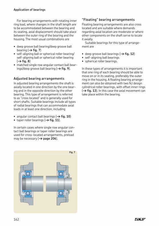
For bearing arrangements with rotating inner ring load, where changes in the shaft length are to be accommodated between the bearing and its seating, axial displacement should take place between the outer ring of the bearing and the housing. The most usual combinations are
• deep groove ball bearing/deep groove ball bearing († fig. 7)
• selfaligning ball or spherical roller bearing/selfaligning ball or spherical roller bearing († fig. 8)
• matched single row angular contact ball bearings/deep groove ball bearing († fig. 9).
Adjusted bearing arrangementsIn adjusted bearing arrangements the shaft is axially located in one direction by the one bearing and in the opposite direction by the other bearing. This type of arrangement is referred to as “cross located” and is generally used for short shafts. Suitable bearings include all types of radial bearings that can accommodate axial loads in at least one direction, including
• angular contact ball bearings († fig. 10)• taper roller bearings († fig. 11).
In certain cases where single row angular contact ball bearings or taper roller bearings are used for crosslocated arrangements, preload may be necessary († page 206).
“Floating” bearing arrangementsFloating bearing arrangements are also cross located and are suitable where demands regarding axial location are moderate or where other components on the shaft serve to locate it axially.
Suitable bearings for this type of arrangement are
• deep groove ball bearings († fig. 12)• selfaligning ball bearings• spherical roller bearings.
In these types of arrangements it is important that one ring of each bearing should be able to move on or in its seating, preferably the outer ring in the housing. A floating bearing arrangement can also be obtained with two NJ design cylindrical roller bearings, with offset inner rings († fig. 13). In this case the axial movement can take place within the bearing.
Fig. 7
Application of bearings
162

Fig. 8
Fig. 9
Fig. 10
Fig. 11
Fig. 12
Fig. 13
163

Radial location of bearingsIf the load carrying ability of a bearing is to be fully utilized, its rings or washers must be fully supported around their complete circumference and across the entire width of the raceway. The support, which must be firm and even can be provided by a cylindrical or tapered seating or, for thrust bearing washers, by a flat (plane) support surface. This means that bearing seatings must be made with adequate accuracy and that their surface should be uninterrupted by grooves, holes or other features. In addition, the bearing rings must be reliably secured to prevent them from turning on or in their seatings under load.
Generally speaking, satisfactory radial location and adequate support can only be obtained when the rings are mounted with an appropriate degree of interference. Inadequately or incorrectly secured bearing rings generally cause damage to the bearings and associated components. However, when easy mounting and dismounting are desirable, or when axial displacement is required with a nonlocating bearing, an interference fit cannot always be used. In certain cases where a loose fit is employed it is necessary to take special precautions to limit the inevitable wear from creep, as for example, by surface hardening of the bearing seating and abutments, lubrication of the mating surfaces via special lubrication grooves and the removal of wear particles, or slots in the bearing ring side faces to accommodate keys or other holding devices.
Selection of fitWhen selecting a fit, the factors discussed in this section should be considered, together with the general guidelines provided.
1. Conditions of rotationConditions of rotation refer to the bearing ring being considered in relation to the direction of the load († table 1). Essentially, there are three different conditions: “rotating load”, “stationary load” and “direction of load indeterminate”.
“Rotating load” pertains if the bearing ring rotates and the load is stationary, or if the ring is stationary and the load rotates so that all points on the raceway are subjected to load in the course of one revolution. Heavy loads which
do not rotate but oscillate, for example, those acting on connecting rod bearings, are generally considered as rotating loads.
A bearing ring subjected to a rotating load will turn (creep or wander) on its seating if mounted with a clearance fit, and wear (fretting corrosion) of the contact surfaces will result. To prevent this, interference fits must be used. The degree of interference needed is dictated by the operating conditions († points 2 and 4 below).
“Stationary load” pertains if the bearing ring is stationary and the load is also stationary, or if the ring and the load rotate at the same speed, so that the load is always directed towards the same position on the raceway. Under these conditions, a bearing ring will normally not turn on its seating. Therefore, the ring need not necessarily have an interference fit, unless this is required for other reasons.
“Direction of load indeterminate” represents variable external loads, shock loads, vibrations and unbalance loads in highspeed machines. These give rise to changes in the direction of load, which cannot be accurately described. When the direction of load is indeterminate and particularly where heavy loads are involved, it is desirable that both rings have an interference fit. For the inner ring the recommended fit for a rotating load is normally used. However, when the outer ring must be free to move axially in the housing, and the load is not heavy, a somewhat looser fit than that recommended for a rotating load may be used.
Application of bearings
164
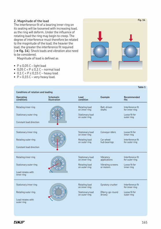
Fig. 142. Magnitude of the load The interference fit of a bearing inner ring on its seating will be loosened with increasing load, as the ring will deform. Under the influence of rotating load the ring may begin to creep. The degree of interference must therefore be related to the magnitude of the load; the heavier the load, the greater the interference fit required († fig. 14). Shock loads and vibration also need to be considered.
Magnitude of load is defined as
• P ≤ 0,05 C – light load • 0,05 C < P ≤ 0,1 C – normal load• 0,1 C < P ≤ 0,15 C – heavy load• P > 0,15 C – very heavy load.
Table 1
Conditions of rotation and loading
Operating Schematic Load Example Recommendedconditions illustration condition fits
Rotating inner ring Rotating load Beltdriven Interference fit on inner ring shafts for inner ring
Stationary outer ring Stationary load Loose fit for on outer ring outer ring
Constant load direction
Stationary inner ring Stationary load Conveyor idlers Loose fit for on inner ring inner ring
Rotating outer ring Rotating load Car wheel Interference fit on outer ring hub bearings for outer ring
Constant load direction
Rotating inner ring Stationary load Vibratory Interference fit on inner ring applications for outer ring
Stationary outer ring Rotating load Vibrating screens Loose fit for on outer ring or motors inner ring
Load rotates with inner ring
Stationary inner ring Rotating load Gyratory crusher Interference fit on inner ring. for inner ring
Rotating outer ring Stationary load (Merrygoround Loose fit for on outer ring drives) outer ring
Load rotates with outer ring
165
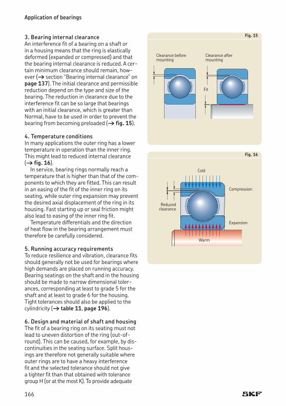
3. Bearing internal clearanceAn interference fit of a bearing on a shaft or in a housing means that the ring is elastically deformed (expanded or compressed) and that the bearing internal clearance is reduced. A certain minimum clearance should remain, however († section “Bearing internal clearance” on page 137). The initial clearance and permissible reduction depend on the type and size of the bearing. The reduction in clearance due to the interference fit can be so large that bearings with an initial clearance, which is greater than Normal, have to be used in order to prevent the bearing from becoming preloaded († fig. 15).
4. Temperature conditionsIn many applications the outer ring has a lower temperature in operation than the inner ring. This might lead to reduced internal clearance († fig. 16).
In service, bearing rings normally reach a temperature that is higher than that of the components to which they are fitted. This can result in an easing of the fit of the inner ring on its seating, while outer ring expansion may prevent the desired axial displacement of the ring in its housing. Fast starting up or seal friction might also lead to easing of the inner ring fit.
Temperature differentials and the direction of heat flow in the bearing arrangement must therefore be carefully considered.
5. Running accuracy requirementsTo reduce resilience and vibration, clearance fits should generally not be used for bearings where high demands are placed on running accuracy. Bearing seatings on the shaft and in the housing should be made to narrow dimensional tolerances, corresponding at least to grade 5 for the shaft and at least to grade 6 for the housing. Tight tolerances should also be applied to the cylindricity († table 11, page 196).
6. Design and material of shaft and housingThe fit of a bearing ring on its seating must not lead to uneven distortion of the ring (outofround). This can be caused, for example, by discontinuities in the seating surface. Split housings are therefore not generally suitable where outer rings are to have a heavy interference fit and the selected tolerance should not give a tighter fit than that obtained with tolerance group H (or at the most K). To provide adequate
Fig. 16
Cold
Reduced clearance
Compression
Expansion
Warm
Fig. 15
Clearance before mounting
Clearance after mounting
Fit
Application of bearings
166

support for bearing rings mounted in thinwalled housings, light alloy housings or on hollow shafts, heavier interference fits than those normally recommended for thickwalled steel or cast iron housings or for solid shafts should be used († section “Fits for hollow shafts”, starting on page 172). Also, sometimes lighter interference fits may be required for certain shaft materials.
7. Ease of mounting and dismountingBearings with clearance fits are usually easier to mount or dismount than those with interference fits. Where operating conditions necessitate interference fits and it is essential that mounting and dismounting can be done easily, separable bearings, or bearings with a tapered bore may be used. Bearings with a tapered bore can be mounted either directly on a tapered shaft seating or via adapter or withdrawal sleeves on smooth or stepped cylindrical shafts († figs. 26, 27 and 28, page 201).
8. Displacement of the non-locating bearingIf bearings that cannot accommodate axial displacement within the bearing are used in the nonlocating position, it is imperative that one of the bearing rings is free to move axially at all times. Adopting a clearance fit for the ring that carries a stationary load will provide this († fig. 20, page 199). When the outer ring is under stationary load so that axial displacement is accommodated or takes place in the housing seating, a hardened intermediate bushing or sleeve is often fitted to the housing bore, for example, where light alloy housings are employed. In this way a “hammering out” of the housing seating because of the lower material hardness is avoided; it would otherwise result in the axial displacement being restricted or even prohibited over time.
If cylindrical roller bearings having one ring without flanges, needle roller bearings or CARB toroidal roller bearings are used, both bearing rings may be mounted with an interference fit because axial displacement will take place within the bearing.
Recommended fitsThe tolerances for the bore and outside diameters of rolling bearings are internationally standardized († section “Tolerances”, starting on page 120).
To achieve an interference or a clearance fit for bearings with a cylindrical bore and cylindrical outside diameter, suitable tolerance ranges for the seatings on the shaft and in the housing bore are selected from the ISO tolerance system. Only a limited number of ISO tolerance grades need be considered for rolling bearing applications. The location of the most commonly used grades relative to the bearing bore and outside diameter tolerances are illustrated in fig. 17, page 168.
Bearings with a tapered bore are mounted either directly on tapered shaft seatings or on adapter or withdrawal sleeves, having an external taper, which are fitted to cylindrical shaft seatings. In these cases, the fit of the bearing inner ring is not determined, as for bearings with a cylindrical bore, by the selected shaft tolerance but by the distance through which the ring is driven up on its tapered seating or sleeve. Special precautions with respect to the reduction of the internal clearance must be observed as mentioned in the sections “Selfaligning ball bearings”, “Spherical roller bearings” and “CARB toroidal roller bearings”.
If the bearings are to be secured using adapter or withdrawal sleeves, larger diameter tolerances are permitted for the sleeve seating, but the tolerances for cylindricity must be tighter († section “Dimensional, form and running accuracy of bearing seatings and abutments”, starting on page 194).
167

Tables with recommendations for fitsRecommendations for bearing fits for solid steel shafts can be found in
Table 2: Radial bearings with cylindrical boreTable 3: Thrust bearings
and for cast iron and steel housings in
Table 4: Radial bearings – nonsplit housingsTable 5: Radial bearings – split or nonsplit
housingsTable 6: Thrust bearings
These recommendations for modern bearings are based on the general selection guidelines described above, developments in bearing design and years of experience for a very wide range of bearing arrangements and applications. Modern bearings can carry substantially greater loads than previous conventional bearings and the recommendations reflect these more demanding conditions.The tables of hous
Fig. 17
ing tolerance recommendations also provide information as to whether the outer ring can be axially displaced in the housing bore. Using this information it is possible to check whether the chosen tolerance is suitable for nonseparable bearings that are to be used in the nonlocating position and cannot accommodate axial displacement within the bearing.
NoteFor applications with stainless steel bearings, the recommended tolerances in tables 2 to 6 on pages 169 to 171 apply, but the restrictions in the footnotes 2) and 3) in table 2 shall be taken into account. The footnote 1) in table 2 is not valid for stainless steel bearings. If tighter fits than those recommended in table 2 are needed, please contact the SKF application engineering service. It also may be necessary to consider the initial bearing clearance, e.g. when using stainless steel shafts at elevated temperatures.
Application of bearings
168
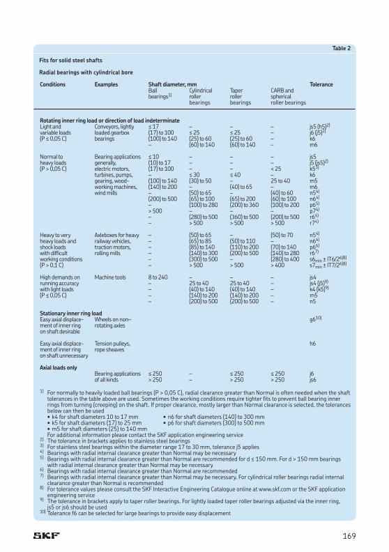
Table 2
Fits for solid steel shafts
Radial bearings with cylindrical bore
Conditions Examples Shaft diameter, mm Tolerance Ball Cylindrical Taper CARB and bearings1) roller roller spherical bearings bearings roller bearings
Rotating inner ring load or direction of load indeterminateLight and Conveyors, lightly ≤ 17 – – – js5 (h5)2)
variable loads loaded gearbox (17) to 100 ≤ 25 ≤ 25 – j6 (j5)2)
(P ≤ 0,05 C) bearings (100) to 140 (25) to 60 (25) to 60 – k6 – (60) to 140 (60) to 140 – m6
Normal to Bearing applications ≤ 10 – – – js5heavy loads generally, (10) to 17 – – – j5 (js5)2)
(P > 0,05 C) electric motors, (17) to 100 – – < 25 k53)
turbines, pumps, – ≤ 30 ≤ 40 – k6 gearing, wood (100) to 140 (30) to 50 – 25 to 40 m5 working machines, (140) to 200 – (40) to 65 – m6 wind mills – (50) to 65 – (40) to 60 n54)
(200) to 500 (65) to 100 (65) to 200 (60) to 100 n64) – (100) to 280 (200) to 360 (100) to 200 p65)
> 500 – – – p74)
– (280) to 500 (360) to 500 (200) to 500 r64)
– > 500 > 500 > 500 r74)
Heavy to very Axleboxes for heavy – (50) to 65 – (50) to 70 n54)
heavy loads and railway vehicles, – (65) to 85 (50) to 110 – n64)
shock loads traction motors, – (85) to 140 (110) to 200 (70) to 140 p66)
with difficult rolling mills – (140) to 300 (200) to 500 (140) to 280 r67)
working conditions – (300) to 500 – (280) to 400 s6min ± IT6/26)8)
(P > 0,1 C) – > 500 > 500 > 400 s7min ± IT7/26)8)
High demands on Machine tools 8 to 240 – – – js4running accuracy – 25 to 40 25 to 40 – js4 (j5)9)
with light loads – (40) to 140 (40) to 140 – k4 (k5)9)
(P ≤ 0,05 C) – (140) to 200 (140) to 200 – m5 – (200) to 500 (200) to 500 – n5
Stationary inner ring loadEasy axial displace Wheels on non– g610)
ment of inner ring rotating axles on shaft desirable Easy axial displace Tension pulleys, h6ment of inner ring rope sheaves on shaft unnecessary
Axial loads only Bearing applications ≤ 250 – ≤ 250 ≤ 250 j6 of all kinds > 250 – > 250 > 250 js6
1) For normally to heavily loaded ball bearings (P > 0,05 C), radial clearance greater than Normal is often needed when the shaft tolerances in the table above are used. Sometimes the working conditions require tighter fits to prevent ball bearing inner rings from turning (creeping) on the shaft. If proper clearance, mostly larger than Normal clearance is selected, the tolerances below can then be used • k4 for shaft diameters 10 to 17 mm • n6 for shaft diameters (140) to 300 mm• k5 for shaft diameters (17) to 25 mm • p6 for shaft diameters (300) to 500 mm• m5 for shaft diameters (25) to 140 mm
For additional information please contact the SKF application engineering service2) The tolerance in brackets applies to stainless steel bearings3) For stainless steel bearings within the diameter range 17 to 30 mm, tolerance j5 applies4) Bearings with radial internal clearance greater than Normal may be necessary5) Bearings with radial internal clearance greater than Normal are recommended for d ≤ 150 mm. For d > 150 mm bearings
with radial internal clearance greater than Normal may be necessary6) Bearings with radial internal clearance greater than Normal are recommended7) Bearings with radial internal clearance greater than Normal may be necessary. For cylindrical roller bearings radial internal
clearance greater than Normal is recommended8) For tolerance values please consult the SKF Interactive Engineering Catalogue online at www.skf.com or the SKF application
engineering service9) The tolerance in brackets apply to taper roller bearings. For lightly loaded taper roller bearings adjusted via the inner ring,
js5 or js6 should be used10) Tolerance f6 can be selected for large bearings to provide easy displacement
169

Table 3
Fits for solid steel shafts
Thrust bearings
Conditions Shaft diameter, Tolerance mm
Axial loads only
Thrust ball bearings – h6Cylindrical roller thrust bearings – h6 (h8)Cylindrical roller and cage thrust assemblies – h8
Combined radial and axial loads acting on spherical roller thrust bearings
Stationary load on shaft washer ≤ 250 j6 > 250 js6Rotating load on shaft washer, ≤ 200 k6or direction of load indeterminate (200) to 400 m6 > 400 n6
Table 4
Fits for cast iron and steel housings
Radial bearings – non-split housings
Conditions Examples Tolerance1) Displacement of outer ring
Rotating outer ring load
Heavy loads on bearings Roller bearing wheel hubs, P7 Cannot be displacedin thinwalled housings, bigend bearings heavy shock loads(P > 0,1 C)
Normal to heavy loads Ball bearing wheel hubs, N7 Cannot be displaced(P > 0,05 C) bigend bearings, crane travelling wheels
Light and variable loads Conveyor rollers, rope sheaves, M7 Cannot be displaced(P ≤ 0,05 C) belt tensioner pulleys
Direction of load indeterminate
Heavy shock loads Electric traction motors M7 Cannot be displaced
Normal to heavy loads Electric motors, pumps, K7 Cannot be displaced (P > 0,05 C), axial displacement crankshaft bearings as a ruleof outer ring unnecessary
Accurate or quiet running2)
Ball bearings Small electric motors J63) Can be displaced
Taper roller bearings When adjusted via the outer ring JS5 – Axially located outer ring K5 – Rotating outer ring load M5 –
1) For ball bearings with D ≤ 100 mm, tolerance grade IT6 is often preferable and is recommend for bearings with thinwalled rings, e.g. in the 7, 8 or 9 Diameter Series. For these series, cylindricity tolerances IT4 are also recommended
2) For highprecision bearings to tolerance class P5 or better, other recommendations apply († the SKF catalogue “High precision bearings”)
3) When easy displacement is required use H6 instead of J6
Application of bearings
170
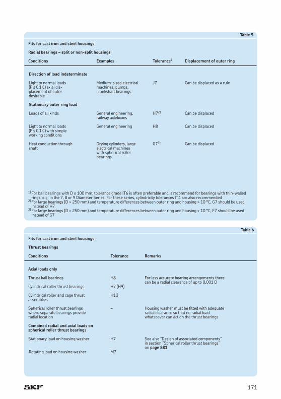
Table 5
Fits for cast iron and steel housings
Radial bearings – split or non-split housings
Conditions Examples Tolerance1) Displacement of outer ring
Direction of load indeterminate
Light to normal loads Mediumsized electrical J7 Can be displaced as a rule(P ≤ 0,1 C) axial dis machines, pumps, placement of outer crankshaft bearings desirable Stationary outer ring load
Loads of all kinds General engineering, H72) Can be displaced railway axleboxes Light to normal loads General engineering H8 Can be displaced(P ≤ 0,1 C) with simple working conditions Heat conduction through Drying cylinders, large G73) Can be displacedshaft electrical machines with spherical roller bearings
1) For ball bearings with D ≤ 100 mm, tolerance grade IT6 is often preferable and is recommend for bearings with thinwalled rings, e.g. in the 7, 8 or 9 Diameter Series. For these series, cylindricity tolerances IT4 are also recommended
2) For large bearings (D > 250 mm) and temperature differences between outer ring and housing > 10 °C, G7 should be used instead of H7
3) For large bearings (D > 250 mm) and temperature differences between outer ring and housing > 10 °C, F7 should be used instead of G7
Table 6
Fits for cast iron and steel housings
Thrust bearings
Conditions Tolerance Remarks
Axial loads only
Thrust ball bearings H8 For less accurate bearing arrangements there can be a radial clearance of up to 0,001 DCylindrical roller thrust bearings H7 (H9) Cylindrical roller and cage thrust H10 assemblies Spherical roller thrust bearings – Housing washer must be fitted with adequate where separate bearings provide radial clearance so that no radial load radial location whatsoever can act on the thrust bearings Combined radial and axial loads onspherical roller thrust bearings
Stationary load on housing washer H7 See also “Design of associated components” in section “Spherical roller thrust bearings” on page 881 Rotating load on housing washer M7
171

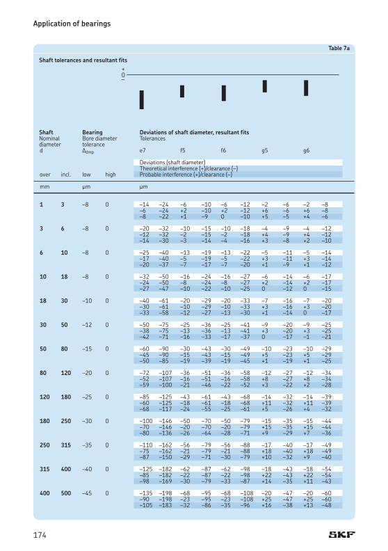
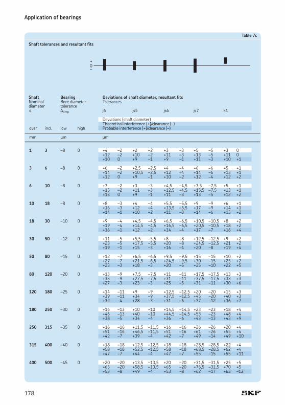
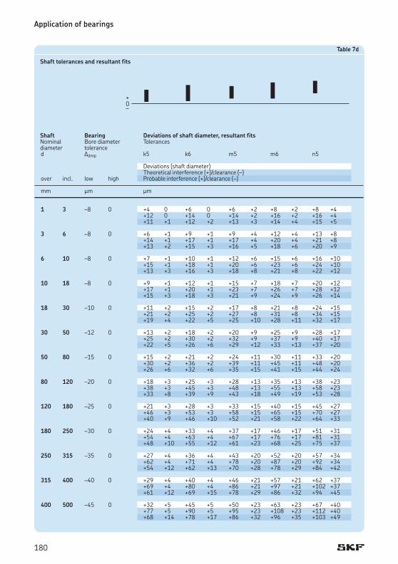
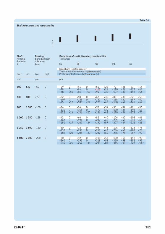
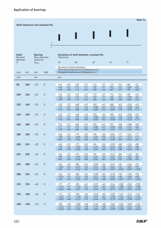
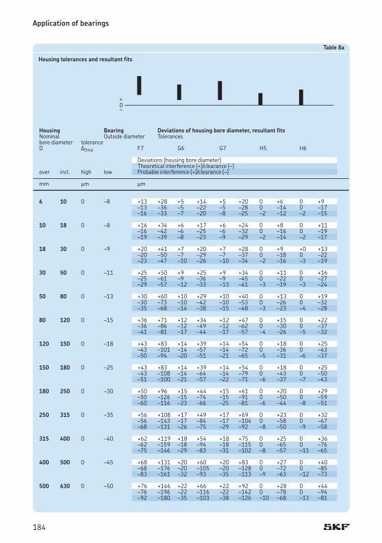
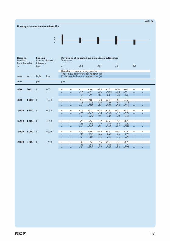
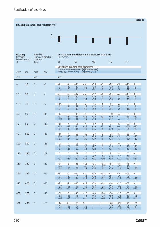
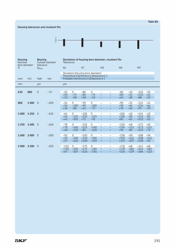
Tolerance tablesThe values shown in tables 7 and 8 for the shaft and housing tolerances enable the character of the fit to be established
• the upper and lower limits of Normal tolerances for the bearing bore and outside diameter deviations
• the upper and lower limits of the shaft and housing bore diameter deviations in accordance with ISO 2862:1988
• the smallest and largest values of the theoretical interference (+) or clearance (–) in the fit
• the smallest and largest values of the probable interference (+) or clearance (–) in the fit.
The appropriate values for rolling bearing seatings on shafts are listed for the tolerances
e7, f5, f6, g5, g6 in table 7a, pages 174 and 175h5, h6, h8, h9, j5 in table 7b, pages 176 and 177j6, js5, js6, js7, k4 in table 7c, pages 178 and 179k5, k6, m5, m6, n5 in table 7d, pages 180 and 181n6, p6, p7, r6, r7 in table 7e, pages 182 and 183
The appropriate values for the rolling bearing housing seatings are listed for the tolerances
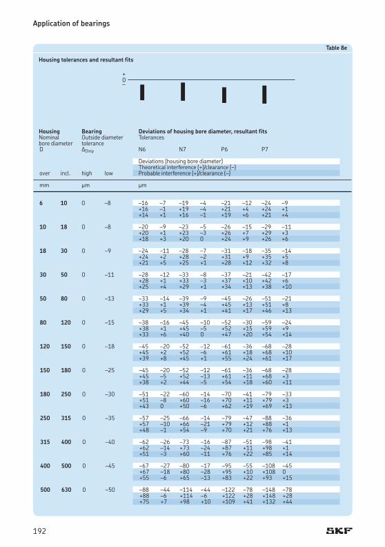
F7, G6, G7, H5, H6 in table 8a, pages 184 and 185H7, H8, H9, H10, J6 in table 8b, pages 186 and 187J7, JS5, JS6, JS7, K5 in table 8c, pages 188 and 189K6, K7, M5, M6, M7 in table 8d, pages 190 and 191N6, N7, P6, P7 in table 8e, pages 192 and 193
The Normal tolerances for the bore and outside diameter for which the limiting values have been calculated are valid for all metric rolling bearings with the exception of metric taper roller bearings when d ≤ 30 mm and D ≤ 150 mm and for thrust bearings when D ≤ 150 mm. The diameter tolerances for these bearings deviate from
the Normal tolerances for the other rolling bearings († tolerance tables on pages 125 to 132).
The values for the probable interference or clearance cover 99 % of all the combinations of the theoretical interference or clearance.
When bearings of higher accuracy than Normal are used, the reduced bore and outside tolerances mean that the interference or clearance of the fits is reduced correspondingly. If, in such cases, a more accurate calculation of the limits is required it is advisable to contact the SKF application engineering service.
Fits for hollow shaftsIf bearings are to be mounted with an interference fit on a hollow shaft it is generally necessary to use a heavier interference fit than would be used for a solid shaft in order to achieve the same surface pressure between the inner ring and shaft seating. The following diameter ratios are important when deciding on the fit to be used
di dci = — and ce = — d de
The fit is not appreciably affected until the diameter ratio of the hollow shaft ci ≥ 0,5. If the average outside diameter of the inner ring is not known, the diameter ratio ce can be calculated with sufficient accuracy using the equation
dce = ————— k (D – d) + d
whereci = diameter ratio of the hollow shaftce = diameter ratio of the inner ringd = outside diameter of the hollow shaft, bore
diameter of the bearing, mmdi = internal diameter of the hollow shaft, mmde = average outside diameter of the inner ring,
mmD = outside bearing diameter, mmk = a factor for the bearing type
for selfaligning ball bearings in the 22 and 23 series, k = 0,25 for cylindrical roller bearings, k = 0,25 for all other bearings, k = 0,3
Application of bearings
172

To determine the requisite interference fit for a bearing to be mounted on a hollow shaft, use the mean probable interference between the shaft seating and bearing bore obtained for the tolerance recommendation for a solid shaft of the same diameter. If the plastic deformation (smoothing) of the mating surfaces produced during mounting is neglected, then the effective interference can be equated to the mean probable interference.
The interference DH needed for a hollow steel shaft can then be determined in relation to the known interference DV for the solid shaft from diagram 1. DV equals the mean value of the smallest and largest values of the probable interference for the solid shaft. The tolerance for the hollow shaft is then selected so that the mean probable interference is as close as possible to the interference DH obtained from diagram 1.
Diagram 1
Relation of interference DH, needed for a hollow steel shaft, to the known interference DV for a solid steel shaft
Example A 6208 deep groove ball bearing with d = 40 mm and D = 80 mm is to be mounted on a hollow shaft having a diameter ratio ci = 0,8. What is the requisite interference and what are the appropriate shaft limits?
If the bearing were to be mounted on a solid steel shaft and subjected to normal loads, a tolerance k5 would be recommended. From table 7d, page 180, a shaft diameter of 40 mm, the mean probable interference DV = (22 + 5)/2 = 13,5 mm. For ci = 0,8 and
40ce = ———————— = 0,77 0,3 (80 – 40) + 40
so that from diagram 1 the ratio DH/DV = 1,7. Thus the requisite interference for the hollow shaft DH = 1,7 ™ 13,5 = 23 mm. Consequently, tolerance m6 is selected for the hollow shaft as this gives a mean probable interference of this order.
173
Application of bearings
1 3 –8 0 –14 –24 –6 –10 –6 –12 –2 –6 –2 –8 –6 –2424 +2 –10 +2 –12 +6 –6 +6 –8 –8 –22 +1 –9 0 –10 +5 –5 +4 –6 3 6 –8 0 –20 –32 –10 –15 –10 –18 –4 –9 –4 –12 –12 –32 –2 –15 –2 –18 +4 –9 +4 –12 –14 –30 –3 –14 –4 –16 +3 –8 +2 –10 6 10 –8 0 –25 –40 –13 –19 –13 –22 –5 –11 –5 –14 –17 –40 –5 –19 –5 –22 +3 –11 +3 –14 –20 –37 –7 –17 –7 –20 +1 –9 +1 –12 10 18 –8 0 –32 –50 –16 –24 –16 –27 –6 –14 –6 –17 –24 –50 –8 –24 –8 –27 +2 –14 +2 –17 –27 –47 –10 –22 –10 –25 0 –12 0 –15 18 30 –10 0 –40 –61 –20 –29 –20 –33 –7 –16 –7 –20 –30 –61 –10 –29 –10 –33 +3 –16 +3 –20 –33 –58 –12 –27 –13 –30 +1 –14 0 –17 30 50 –12 0 –50 –75 –25 –36 –25 –41 –9 –20 –9 –25 –38 –75 –13 –36 –13 –41 +3 –20 +3 –25 –42 –71 –16 –33 –17 –37 0 –17 –1 –21 50 80 –15 0 –60 –90 –30 –43 –30 –49 –10 –23 –10 –29 –45 –90 –15 –43 –15 –49 +5 –23 +5 –29 –50 –85 –19 –39 –19 –45 +1 –19 +1 –25 80 120 –20 0 –72 –107 –36 –51 –36 –58 –12 –27 –12 –34 –52 –107 –16 –51 –16 –58 +8 –27 +8 –34 –59 –100 –21 –46 –22 –52 +3 –22 +2 –28 120 180 –25 0 –85 –125 –43 –61 –43 –68 –14 –32 –14 –39 –60 –125 –18 –61 –18 –68 +11 –32 +11 –39 –68 –117 –24 –55 –25 –61 +5 –26 +4 –32 180 250 –30 0 –100 –146 –50 –70 –50 –79 –15 –35 –15 –44 –70 –146 –20 –70 –20 –79 +15 –35 +15 –44 –80 –136 –26 –64 –28 –71 +9 –29 +7 –36 250 315 –35 0 –110 –162 –56 –79 –56 –88 –17 –40 –17 –49 –75 –162 –21 –79 –21 –88 +18 –40 +18 –49 –87 –150 –29 –71 –30 –79 +10 –32 +9 –40 315 400 –40 0 –125 –182 –62 –87 –62 –98 –18 –43 –18 –54 –85 –182 –22 –87 –22 –98 +22 –43 +22 –54 –98 –169 –30 –79 –33 –87 +14 –35 +11 –43 400 500 –45 0 –135 –198 –68 –95 –68 –108 –20 –47 –20 –60 –90 –198 –23 –95 –23 –108 +25 –47 +25 –60 –105 –183 –32 –86 –35 –96 +16 –38 +13 –48
Table 7a
Shaft tolerances and resultant fits
Shaft Bearing Deviations of shaft diameter, resultant fitsNominal Bore diameter Tolerancesdiameter tolerance d Ddmp e7 f5 f6 g5 g6
Deviations (shaft diameter) Theoretical interference (+)/clearance (–)over incl. low high Probable interference (+)/clearance (–)
mm mm mm
174

500 630 –50 0 –145 –215 –76 –104 –76 –120 –22 –50 –22 –66 –95 –215 –26 –104 –26 –120 +28 –50 +28 –66 –111 –199 –36 –94 –39 –107 +18 –40 +15 –53
630 800 –75 0 –160 –240 –80 –112 –80 –130 –24 –56 –24 –74 –85 –240 –5 –112 –5 –130 +51 –56 +51 –74 –107 –218 –17 –100 –22 –113 +39 –44 +34 –57 800 1 000 –100 0 –170 –260 –86 –122 –86 –142 –26 –62 –26 –82 –70 –260 +14 –122 +14 –142 +74 –62 +74 –82 –97 –233 0 –108 –6 –122 +60 –48 +54 –62 1 000 1 250 –125 0 –195 –300 –98 –140 –98 –164 –28 –70 –28 –94 –70 –300 +27 –140 +27 –164 +97 –70 +97 –94 –103 –267 +10 –123 +3 –140 +80 –53 +73 –70
1 250 1 600 –160 0 –220 –345 –110 –160 –110 –188 –30 –80 –30 –108 –60 –345 +50 –160 +50 –188 +130 –80 +130 –108 –100 –305 +29 –139 +20 –158 +109 –59 +100 –78
1 600 2 000 –200 0 –240 –390 –120 –180 –120 –212 –32 –92 –32 –124 –40 –390 +80 –180 +80 –212 +168 –92 +168 –124 –90 –340 +55 –155 +45 –177 +143 –67 +133 –89
Table 7a
Shaft tolerances and resultant fits
Shaft Bearing Deviations of shaft diameter, resultant fitsNominal Bore diameter Tolerancesdiameter tolerance d Ddmp e7 f5 f6 g5 g6
Deviations (shaft diameter) Theoretical interference (+)/clearance (–)over incl. low high Probable interference (+)/clearance (–)
mm mm mm
175

Application of bearings
1 3 –8 0 0 –4 0 –6 0 –14 0 –25 +2 –2 +8 –4 +8 –6 +8 –14 +8 –25 +10 –2 +7 –3 +6 –4 +6 –12 +5 –22 +9 –1 3 6 –8 0 0 –5 0 –8 0 –18 0 –30 +3 –2 +8 –5 +8 –8 +8 –18 +8 –30 +11 –2 +7 –4 +6 –6 +5 –15 +5 –27 +10 –1 6 10 –8 0 0 –6 0 –9 0 –22 0 –36 +4 –2 +8 –6 +8 –9 +8 –22 +8 –36 +12 –2 +6 –4 +6 –7 +5 –19 +5 –33 +10 0 10 18 –8 0 0 –8 0 –11 0 –27 0 –43 +5 –3 +8 –8 +8 –11 +8 –27 +8 –43 +13 –3 +6 –6 +6 –9 +5 –24 +5 –40 +11 –1 18 30 –10 0 0 –9 0 –13 0 –33 0 –52 +5 –4 +10 –9 +10 –13 +10 –33 +10 –52 +15 –4 +8 –7 +7 –10 +6 –29 +6 –48 +13 –2 30 50 –12 0 0 –11 0 –16 0 –39 0 –62 +6 –5 +12 –11 +12 –16 +12 –39 +12 –62 +18 –5 +9 –8 +8 –12 +7 –34 +7 –57 +15 –2 50 80 –15 0 0 –13 0 –19 0 –46 0 –74 +6 –7 +15 –13 +15 –19 +15 –46 +15 –74 +21 –7 +11 –9 +11 –15 +9 –40 +9 –68 +17 –3 80 120 –20 0 0 –15 0 –22 0 –54 0 –87 +6 –9 +20 –15 +20 –22 +20 –54 +20 –87 +26 –9 +15 –10 +14 –16 +12 –46 +12 –79 +21 –4 120 180 –25 0 0 –18 0 –25 0 –63 0 –100 +7 –11 +25 –18 +25 –25 +25 –63 +25 –100 +32 –11 +19 –12 +18 –18 +15 –53 +15 –90 +26 –5 180 250 –30 0 0 –20 0 –29 0 –72 0 –115 +7 –13 +30 –20 +30 –29 +30 –72 +30 –115 +37 –13 +24 –14 +22 –21 +18 –60 +17 –102 +31 –7 250 315 –35 0 0 –23 0 –32 0 –81 0 –130 +7 –16 +35 –23 +35 –32 +35 –81 +35 –130 +42 –16 +27 –15 +26 –23 +22 –68 +20 –115 +34 –8 315 400 –40 0 0 –25 0 –36 0 –89 0 –140 +7 –18 +40 –25 +40 –36 +40 –89 +40 –140 +47 –18 +32 –17 +29 –25 +25 –74 +23 –123 +39 –10 400 500 –45 0 0 –27 0 –40 0 –97 0 –155 +7 –20 +45 –27 +45 –40 +45 –97 +45 –155 +52 –20 +36 –18 +33 –28 +28 –80 +26 –136 +43 –11
Table 7b
Shaft tolerances and resultant fits
Shaft Bearing Deviations of shaft diameter, resultant fitsNominal Bore diameter Tolerancesdiameter tolerance d Ddmp h5 h6 h8 h9 j5
Deviations (shaft diameter) Theoretical interference (+)/clearance (–)over incl. low high Probable interference (+)/clearance (–)
mm mm mm
176
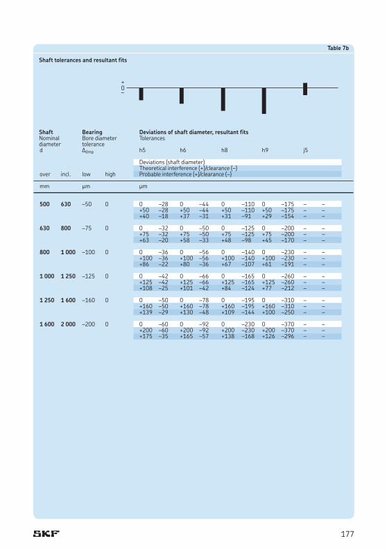
500 630 –50 0 0 –28 0 –44 0 –110 0 –175 – – +50 –28 +50 –44 +50 –110 +50 –175 – – +40 –18 +37 –31 +31 –91 +29 –154 – –
630 800 –75 0 0 –32 0 –50 0 –125 0 –200 – – +75 –32 +75 –50 +75 –125 +75 –200 – – +63 –20 +58 –33 +48 –98 +45 –170 – – 800 1 000 –100 0 0 –36 0 –56 0 –140 0 –230 – – +100 –36 +100 –56 +100 –140 +100 –230 – – +86 –22 +80 –36 +67 –107 +61 –191 – – 1 000 1 250 –125 0 0 –42 0 –66 0 –165 0 –260 – – +125 –42 +125 –66 +125 –165 +125 –260 – – +108 –25 +101 –42 +84 –124 +77 –212 – – 1 250 1 600 –160 0 0 –50 0 –78 0 –195 0 –310 – – +160 –50 +160 –78 +160 –195 +160 –310 – – +139 –29 +130 –48 +109 –144 +100 –250 – – 1 600 2 000 –200 0 0 –60 0 –92 0 –230 0 –370 – – +200 –60 +200 –92 +200 –230 +200 –370 – – +175 –35 +165 –57 +138 –168 +126 –296 – –
Table 7b
Shaft tolerances and resultant fits
Shaft Bearing Deviations of shaft diameter, resultant fitsNominal Bore diameter Tolerancesdiameter tolerance d Ddmp h5 h6 h8 h9 j5
Deviations (shaft diameter) Theoretical interference (+)/clearance (–)over incl. low high Probable interference (+)/clearance (–)
mm mm mm
177
Application of bearings
1 3 –8 0 +4 –2 +2 –2 +3 –3 +5 –5 +3 0 +12 –2 +10 –2 +11 –3 +13 –5 +11 0 +10 0 +9 –1 +9 –1 +11 –3 +10 +1 3 6 –8 0 +6 –2 +2,5 –2,5 +4 –4 +6 –6 +5 +1 +14 –2 +10,5 –2,5 +12 –4 +14 –6 +13 +1 +12 0 +9 –1 +10 –2 +12 –4 +12 +2 6 10 –8 0 +7 –2 +3 –3 +4,5 –4,5 +7,5 –7,5 +5 +1 +15 –2 +11 –3 +12,5 –4,5 +15,5 –7,5 +13 +1 +13 0 +9 –1 +11 –3 +13 –5 +12 +2 10 18 –8 0 +8 –3 +4 –4 +5,5 –5,5 +9 –9 +6 +1 +16 –3 +12 –4 +13,5 –5,5 +17 –9 +14 +1 +14 –1 +10 –2 +11 –3 +14 –6 +13 +2 18 30 –10 0 +9 –4 +4,5 –4,5 +6,5 –6,5 +10,5 –10,5 +8 +2 +19 –4 +14,5 –4,5 +16,5 –6,5 +20,5 –10,5 +18 +2 +16 –1 +12 –2 +14 –4 +17 –7 +16 +4 30 50 –12 0 +11 –5 +5,5 –5,5 +8 –8 +12,5 –12,5 +9 +2 +23 –5 +17,5 –5,5 +20 –8 +24,5 –12,5 +21 +2 +19 –1 +15 –3 +16 –4 +20 –8 +19 +4 50 80 –15 0 +12 –7 +6,5 –6,5 +9,5 –9,5 +15 –15 +10 +2 +27 –7 +21,5 –6,5 +24,5 –9,5 +30 –15 +25 +2 +23 –3 +18 –3 +20 –5 +25 –10 +22 +5 80 120 –20 0 +13 –9 +7,5 –7,5 +11 –11 +17,5 –17,5 +13 +3 +33 –9 +27,5 –7,5 +31 –11 +37,5 –17,5 +33 +3 +27 –3 +23 –3 +25 –5 +31 –11 +30 +6 120 180 –25 0 +14 –11 +9 –9 +12,5 –12,5 +20 –20 +15 +3 +39 –11 +34 –9 +37,5 –12,5 +45 –20 +40 +3 +32 –4 +28 –3 +31 –6 +37 –12 +36 +7 180 250 –30 0 +16 –13 +10 –10 +14,5 –14,5 +23 –23 +18 +4 +46 –13 +40 –10 +44,5 –14,5 +53 –23 +48 +4 +38 –5 +34 –4 +36 –6 +43 –13 +43 +9 250 315 –35 0 +16 –16 +11,5 –11,5 +16 –16 +26 –26 +20 +4 +51 –16 +46,5 –11,5 +51 –16 +61 –26 +55 +4 +42 –7 +39 –4 +42 –7 +49 –14 +49 +10 315 400 –40 0 +18 –18 +12,5 –12,5 +18 –18 +28,5 –28,5 +22 +4 +58 –18 +52,5 –12,5 +58 –18 +68,5 –28,5 +62 +4 +47 –7 +44 –4 +47 –7 +55 –15 +55 +11 400 500 –45 0 +20 –20 +13,5 –13,5 +20 –20 +31,5 –31,5 +25 +5 +65 –20 +58,5 –13,5 +65 –20 +76,5 –31,5 +70 +5 +53 –8 +49 –4 +53 –8 +62 –17 +63 –12
Table 7c
Shaft tolerances and resultant fits
Shaft Bearing Deviations of shaft diameter, resultant fitsNominal Bore diameter Tolerancesdiameter tolerance d Ddmp j6 js5 js6 js7 k4
Deviations (shaft diameter) Theoretical interference (+)/clearance (–)over incl. low high Probable interference (+)/clearance (–)
mm mm mm
178

500 630 –50 0 +22 –22 +14 –14 +22 –22 +35 –35 – – +72 –22 +64 –14 +72 –22 +85 –35 – – +59 –9 +54 –4 +59 –9 +69 –19 – –
630 800 –75 0 +25 –25 +16 –16 +25 –25 +40 –40 – – +100 –25 +91 –16 +100 –25 +115 –40 – – +83 –8 +79 –4 +83 –8 +93 –18 – – 800 1 000 –100 0 +28 –28 +18 –18 +28 –28 +45 –45 – – +128 –28 +118 –18 +128 –28 +145 –45 – – +108 –8 +104 –4 +108 –8 +118 –18 – – 1 000 1 250 –125 0 +33 –33 +21 –21 +33 –33 +52 –52 – – +158 –33 +146 –21 +158 –33 +177 –52 – – +134 –9 +129 –4 +134 –9 +145 –20 – – 1 250 1 600 –160 0 +39 –39 +25 –25 +39 –39 +62 –62 – – +199 –39 +185 –25 +199 –39 +222 –62 – – +169 –9 +164 –4 +169 –9 +182 –22 – – 1 600 2 000 –200 0 +46 –46 +30 –30 +46 –46 +75 –75 – – +246 –46 +230 –30 +246 –46 +275 –75 – – +211 –11 +205 –5 +211 –11 +225 –25 – –
Table 7c
Shaft tolerances and resultant fits
Shaft Bearing Deviations of shaft diameter, resultant fitsNominal Bore diameter Tolerancesdiameter tolerance d Ddmp j6 js5 js6 js7 k4
Deviations (shaft diameter) Theoretical interference (+)/clearance (–)over incl. low high Probable interference (+)/clearance (–)
mm mm mm
179
Application of bearings
1 3 –8 0 +4 0 +6 0 +6 +2 +8 +2 +8 +4 +12 0 +14 0 +14 +2 +16 +2 +16 +4 +11 +1 +12 +2 +13 +3 +14 +4 +15 +5 3 6 –8 0 +6 +1 +9 +1 +9 +4 +12 +4 +13 +8 +14 +1 +17 +1 +17 +4 +20 +4 +21 +8 +13 +2 +15 +3 +16 +5 +18 +6 +20 +9 6 10 –8 0 +7 +1 +10 +1 +12 +6 +15 +6 +16 +10 +15 +1 +18 +1 +20 +6 +23 +6 +24 +10 +13 +3 +16 +3 +18 +8 +21 +8 +22 +12 10 18 –8 0 +9 +1 +12 +1 +15 +7 +18 +7 +20 +12 +17 +1 +20 +1 +23 +7 +26 +7 +28 +12 +15 +3 +18 +3 +21 +9 +24 +9 +26 +14 18 30 –10 0 +11 +2 +15 +2 +17 +8 +21 +8 +24 +15 +21 +2 +25 +2 +27 +8 +31 +8 +34 +15 +19 +4 +22 +5 +25 +10 +28 +11 +32 +17 30 50 –12 0 +13 +2 +18 +2 +20 +9 +25 +9 +28 +17 +25 +2 +30 +2 +32 +9 +37 +9 +40 +17 +22 +5 +26 +6 +29 +12 +33 +13 +37 +20 50 80 –15 0 +15 +2 +21 +2 +24 +11 +30 +11 +33 +20 +30 +2 +36 +2 +39 +11 +45 +11 +48 +20 +26 +6 +32 +6 +35 +15 +41 +15 +44 +24 80 120 –20 0 +18 +3 +25 +3 +28 +13 +35 +13 +38 +23 +38 +3 +45 +3 +48 +13 +55 +13 +58 +23 +33 +8 +39 +9 +43 +18 +49 +19 +53 +28 120 180 –25 0 +21 +3 +28 +3 +33 +15 +40 +15 +45 +27 +46 +3 +53 +3 +58 +15 +65 +15 +70 +27 +40 +9 +46 +10 +52 +21 +58 +22 +64 +33 180 250 –30 0 +24 +4 +33 +4 +37 +17 +46 +17 +51 +31 +54 +4 +63 +4 +67 +17 +76 +17 +81 +31 +48 +10 +55 +12 +61 +23 +68 +25 +75 +37 250 315 –35 0 +27 +4 +36 +4 +43 +20 +52 +20 +57 +34 +62 +4 +71 +4 +78 +20 +87 +20 +92 +34 +54 +12 +62 +13 +70 +28 +78 +29 +84 +42 315 400 –40 0 +29 +4 +40 +4 +46 +21 +57 +21 +62 +37 +69 +4 +80 +4 +86 +21 +97 +21 +102 +37 +61 +12 +69 +15 +78 +29 +86 +32 +94 +45 400 500 –45 0 +32 +5 +45 +5 +50 +23 +63 +23 +67 +40 +77 +5 +90 +5 +95 +23 +108 +23 +112 +40 +68 +14 +78 +17 +86 +32 +96 +35 +103 +49
Table 7d
Shaft tolerances and resultant fits
Shaft Bearing Deviations of shaft diameter, resultant fitsNominal Bore diameter Tolerancesdiameter tolerance d Ddmp k5 k6 m5 m6 n5
Deviations (shaft diameter) Theoretical interference (+)/clearance (–)over incl. low high Probable interference (+)/clearance (–)
mm mm mm
180
500 630 –50 0 +29 0 +44 0 +55 +26 +70 +26 +73 +44 +78 0 +94 0 +105 +26 +120 +26 +122 +44 +68 +10 +81 +13 +94 +36 +107 +39 +112 +54
630 800 –75 0 +32 0 +50 0 +62 +30 +80 +30 +82 +50 +107 0 +125 0 +137 +30 +155 +30 +157 +50 +95 +12 +108 +17 +125 +42 +138 +47 +145 +62 800 1 000 –100 0 +36 0 +56 0 +70 +34 +90 +34 +92 +56 +136 0 +156 0 +170 +34 +190 +34 +192 +56 +122 +14 +136 +20 +156 +48 +170 +54 +178 +70 1 000 1 250 –125 0 +42 0 +66 0 +82 +40 +106 +40 +108 +66 +167 0 +191 0 +207 +40 +231 +40 +233 +66 +150 +17 +167 +24 +190 +57 +207 +64 +216 +83 1 250 1 600 –160 0 +50 0 +78 0 +98 +48 +126 +48 +128 +78 +210 0 +238 0 +258 +48 +286 +48 +288 +78 +189 +21 +208 +30 +237 +69 +256 +78 +267 +99 1 600 2 000 –200 0 +60 0 +92 0 +118 +58 +150 +58 +152 +92 +260 0 +292 0 +318 +58 +350 +58 +352 +92 +235 +25 +257 +35 +293 +83 +315 +93 +327 +117
Table 7d
Shaft tolerances and resultant fits
Shaft Bearing Deviations of shaft diameter, resultant fitsNominal Bore diameter Tolerancesdiameter tolerance d Ddmp k5 k6 m5 m6 n5
Deviations (shaft diameter) Theoretical interference (+)/clearance (–)over incl. low high Probable interference (+)/clearance (–)
mm mm mm
181
Application of bearings
80 100 –20 0 +45 +23 +59 +37 +72 +37 +73 +51 +86 +51 +65 +23 +79 +37 +92 +37 +93 +51 +106 +51 +59 +29 +73 +43 +85 +44 +87 +57 +99 +58 100 120 –20 0 +45 +23 +59 +37 +72 +37 +76 +54 +89 +54 +65 +23 +79 +37 +92 +37 +96 +54 +109 +54 +59 +29 +73 +43 +85 +44 +90 +60 +102 +61 120 140 –25 0 +52 +27 +68 +43 +83 +43 +88 +63 +103 +63 +77 +27 +93 +43 +108 +43 +113 +63 +128 +63 +70 +34 +86 +50 +100 +51 +106 +70 +120 +71 140 160 –25 0 +52 +27 +68 +43 +83 +43 +90 +65 +105 +65 +77 +27 +93 +43 +108 +43 +115 +65 +130 +65 +70 +34 +86 +50 +100 +51 +108 +72 +122 +73 160 180 –25 0 +52 +27 +68 +43 +83 +43 +93 +68 +108 +68 +77 +27 +93 +43 +108 +43 +118 +68 +133 +68 +70 +34 +86 +50 +100 +51 +111 +75 +125 +76
180 200 –30 0 +60 +31 +79 +50 +96 +50 +106 +77 +123 +77 +90 +31 +109 +50 +126 +50 +136 +77 +153 +77 +82 +39 +101 +58 +116 +60 +128 +85 +143 +87
200 225 –30 0 +60 +31 +79 +50 +96 +50 +109 +80 +126 +80 +90 +31 +109 +50 +126 +50 +139 +80 +156 +80 +82 +39 +101 +58 +116 +60 +131 +88 +146 +90 225 250 –30 0 +60 +31 +79 +50 +96 +50 +113 +84 +130 +84 +90 +31 +109 +50 +126 +50 +143 +84 +160 +84 +82 +39 +101 +58 +116 +60 +135 +92 +150 +94 250 280 –35 0 +66 +34 +88 +56 +108 +56 +126 +94 +146 +94 +101 +34 +123 +56 +143 +56 +161 +94 +181 +94 +92 +43 +114 +65 +131 +68 +152 +103 +169 +106 280 315 –35 0 +66 +34 +88 +56 +108 +56 +130 +98 +150 +98 +101 +34 +123 +56 +143 +56 +165 +98 +185 +98 +92 +43 +114 +65 +131 +68 +156 +107 +173 +110 315 355 –40 0 +73 +37 +98 +62 +119 +62 +144 +108 +165 +108 +113 +37 +138 +62 +159 +62 +184 +108 +205 +108 +102 +48 +127 +73 +146 +75 +173 +119 +192 +121 355 400 –40 0 +73 +37 +98 +62 +119 +62 +150 +114 +171 +114 +113 +37 +138 +62 +159 +62 +190 +114 +211 +114 +102 +48 +127 +73 +146 +75 +179 +125 +198 +127 400 450 –45 0 +80 +40 +108 +68 +131 +68 +166 +126 +189 +126 +125 +40 +153 +68 +176 +68 +211 +126 +234 +126 +113 +52 +141 +80 +161 +83 +199 +138 +219 +141
Table 7e
Shaft tolerances and resultant fits
Shaft Bearing Deviations of shaft diameter, resultant fitsNominal Bore diameter Tolerancesdiameter tolerance d Ddmp n6 p6 p7 r6 r7
Deviations (shaft diameter) Theoretical interference (+)/clearance (–)over incl. low high Probable interference (+)/clearance (–)
mm mm mm
182

450 500 –45 0 +80 +40 +108 +68 +131 +68 +172 +132 +195 +132 +125 +40 +153 +68 +176 +68 +217 +132 +240 +132 +113 +52 +141 +80 +161 +83 +205 +144 +225 +147
500 560 –50 0 +88 +44 +122 +78 +148 +78 +194 +150 +220 +150 +138 +44 +172 +78 +198 +78 +244 +150 +270 +150 +125 +57 +159 +91 +182 +94 +231 +163 +254 +166 560 630 –50 0 +88 +44 +122 +78 +148 +78 +199 +155 +225 +155 +138 +44 +172 +78 +198 +78 +249 +155 +275 +155 +125 +57 +159 +91 +182 +94 +236 +168 +259 +171 630 710 –75 0 +100 +50 +138 +88 +168 +88 +225 +175 +255 +175 +175 +50 +213 +88 +243 +88 +300 +175 +330 +175 +158 +67 +196 +105 +221 +110 +283 +192 +308 +197 710 800 –75 0 +100 +50 +138 +88 +168 +88 +235 +185 +265 +185 +175 +50 +213 +88 +243 +88 +310 +185 +340 +185 +158 +67 +196 +105 +221 +110 +293 +202 +318 +207
800 900 –100 0 +112 +56 +156 +100 +190 +100 +266 +210 +300 +210 +212 +56 +256 +100 +290 +100 +366 +210 +400 +210 +192 +76 +236 +120 +263 +127 +346 +230 +373 +237 900 1 000 –100 0 +112 +56 +156 +100 +190 +100 +276 +220 +310 +220 +212 +56 +256 +100 +290 +100 +376 +220 +410 +220 +192 +76 +236 +120 +263 +127 +356 +240 +383 +247
1 000 1 120 –125 0 +132 +66 +186 +120 +225 +120 +316 +250 +355 +250 +257 +66 +311 +120 +350 +120 +441 +250 +480 +250 +233 +90 +287 +144 +317 +153 +417 +274 +447 +283 1 120 1 250 –125 0 +132 +66 +186 +120 +225 +120 +326 +260 +365 +260 +257 +66 +311 +120 +350 +120 +451 +260 +490 +260 +233 +90 +287 +144 +317 +153 +427 +284 +457 +293 1 250 1 400 –160 0 +156 +78 +218 +140 +265 +140 +378 +300 +425 +300 +316 +78 +378 +140 +425 +140 +538 +300 +585 +300 +286 +108 +348 +170 +385 +180 +508 +330 +545 +340 1 400 1 600 –160 0 +156 +78 +218 +140 +265 +140 +408 +330 +455 +330 +316 +78 +378 +140 +425 +140 +568 +330 +615 +330 +286 +108 +348 +170 +385 +180 +538 +360 +575 +370 1 600 1 800 –200 0 +184 +92 +262 +170 +320 +170 +462 +370 +520 +370 +384 +92 +462 +170 +520 +170 +662 +370 +720 +370 +349 +127 +427 +205 +470 +220 +627 +405 +670 +420 1 800 2 000 –200 0 +184 +92 +262 +170 +320 +170 +492 +400 +550 +400 +384 +92 +462 +170 +520 +170 +692 +400 +750 +400 +349 +127 +427 +205 +470 +220 +657 +435 +700 +450
Table 7e
Shaft tolerances and resultant fits
Shaft Bearing Deviations of shaft diameter, resultant fitsNominal Bore diameter Tolerancesdiameter tolerance d Ddmp n6 p6 p7 r6 r7
Deviations (shaft diameter) Theoretical interference (+)/clearance (–)over incl. low high Probable interference (+)/clearance (–)
mm mm mm
183
Application of bearings
6 10 0 –8 +13 +28 +5 +14 +5 +20 0 +6 0 +9 –13 –36 –5 –22 –5 –28 0 –14 0 –17 –16 –33 –7 –20 –8 –25 –2 –12 –2 –15 10 18 0 –8 +16 +34 +6 +17 +6 +24 0 +8 0 +11 –16 –42 –6 –25 –6 –32 0 –16 0 –19 –19 –39 –8 –23 –9 –29 –2 –14 –2 –17 18 30 0 –9 +20 +41 +7 +20 +7 +28 0 +9 +0 +13 –20 –50 –7 –29 –7 –37 0 –18 0 –22 –23 –47 –10 –26 –10 –34 –2 –16 –3 –19 30 50 0 –11 +25 +50 +9 +25 +9 +34 0 +11 0 +16 –25 –61 –9 –36 –9 –45 0 –22 0 –27 –29 –57 –12 –33 –13 –41 –3 –19 –3 –24 50 80 0 –13 +30 +60 +10 +29 +10 +40 0 +13 0 +19 –30 –73 –10 –42 –10 –53 0 –26 0 –32 –35 –68 –14 –38 –15 –48 –3 –23 –4 –28 80 120 0 –15 +36 +71 +12 +34 +12 +47 0 +15 0 +22 –36 –86 –12 –49 –12 –62 0 –30 0 –37 –41 –81 –17 –44 –17 –57 –4 –26 –5 –32 120 150 0 –18 +43 +83 +14 +39 +14 +54 0 +18 0 +25 –43 –101 –14 –57 –14 –72 0 –36 0 –43 –50 –94 –20 –51 –21 –65 –5 –31 –6 –37 150 180 0 –25 +43 +83 +14 +39 +14 +54 0 +18 0 +25 –43 –108 –14 –64 –14 –79 0 –43 0 –50 –51 –100 –21 –57 –22 –71 –6 –37 –7 –43 180 250 0 –30 +50 +96 +15 +44 +15 +61 0 +20 0 +29 –50 –126 –15 –74 –15 –91 0 –50 0 –59 –60 –116 –23 –66 –25 –81 –6 –44 –8 –51 250 315 0 –35 +56 +108 +17 +49 +17 +69 0 +23 0 +32 –56 –143 –17 –84 –17 –104 0 –58 0 –67 –68 –131 –26 –75 –29 –92 –8 –50 –9 –58 315 400 0 –40 +62 +119 +18 +54 +18 +75 0 +25 0 +36 –62 –159 –18 –94 –18 –115 0 –65 0 –76 –75 –146 –29 –83 –31 –102 –8 –57 –11 –65 400 500 0 –45 +68 +131 +20 +60 +20 +83 0 +27 0 +40 –68 –176 –20 –105 –20 –128 0 –72 0 –85 –83 –161 –32 –93 –35 –113 –9 –63 –12 –73 500 630 0 –50 +76 +146 +22 +66 +22 +92 0 +28 0 +44 –76 –196 –22 –116 –22 –142 0 –78 0 –94 –92 –180 –35 –103 –38 –126 –10 –68 –13 –81
Table 8a
Housing tolerances and resultant fits
Housing Bearing Deviations of housing bore diameter, resultant fitsNominal Outside diameter Tolerancesbore diameter tolerance D DDmp F7 G6 G7 H5 H6
Deviations (housing bore diameter) Theoretical interference (+)/clearance (–)over incl. high low Probable interference (+)/clearance (–)
mm mm mm
184

630 800 0 –75 +80 +160 +24 +74 +24 +104 0 +32 0 +50 –80 –235 –24 –149 –24 –179 0 –107 0 –125 –102 –213 –41 –132 –46 –157 –12 –95 –17 –108
800 1 000 0 –100 +86 +176 +26 +82 +26 +116 0 +36 0 +56 –86 –276 –26 –182 –26 –216 0 –136 0 –156 –113 –249 –46 –162 –53 –189 –14 –122 –20 –136 1 000 1 250 0 –125 +98 +203 +28 +94 +28 +133 0 +42 0 +66 –98 –328 –28 –219 –28 –258 0 –167 0 –191 –131 –295 –52 –195 –61 –225 –17 –150 –24 –167 1 250 1 600 0 –160 +110 +235 +30 +108 +30 +155 0 +50 0 +78 –110 –395 –30 –268 –30 –315 0 –210 0 –238 –150 –355 –60 –238 –70 –275 –21 –189 –30 –208 1 600 2 000 0 –200 +120 +270 +32 +124 +32 +182 0 +60 0 +92 –120 –470 –32 –324 –32 –382 0 –260 0 –292 –170 –420 –67 –289 –82 –332 –25 –235 –35 –257 2 000 2 500 0 –250 +130 +305 +34 +144 +34 +209 0 +70 0 +110 –130 –555 –34 –394 –34 –459 0 –320 0 –360 –189 –496 –77 –351 –93 –400 –30 –290 –43 –317
Table 8a
Housing tolerances and resultant fits
Housing Bearing Deviations of housing bore diameter, resultant fitsNominal Outside diameter Tolerancesbore diameter tolerance D DDmp F7 G6 G7 H5 H6
Deviations (housing bore diameter) Theoretical interference (+)/clearance (–)over incl. high low Probable interference (+)/clearance (–)
mm mm mm
185

Application of bearings
6 10 0 –8 0 +15 0 +22 0 +36 0 +58 –4 +5 0 –23 0 –30 0 –44 0 –66 +4 –13 –3 –20 –3 –27 –3 –41 –3 –63 +2 –11 10 18 0 –8 0 +18 0 +27 0 +43 0 +70 –5 +6 0 –26 0 –35 0 –51 0 –78 +5 –14 –3 –23 –3 –32 –3 –48 –3 –75 +3 –12 18 30 0 –9 0 +21 0 +33 0 +52 0 +84 –5 +8 0 –30 0 –42 0 –61 0 –93 +5 –17 –3 –27 –3 –39 –4 –57 –4 –89 +2 –14 30 50 0 –11 0 +25 0 +39 0 +62 0 +100 –6 +10 0 –36 0 –50 0 –73 0 –111 +6 –21 –4 –32 –4 –46 –5 –68 –5 –106 +3 –18 50 80 0 –13 0 +30 0 +46 0 +74 0 +120 –6 +13 0 –43 0 –59 0 –87 0 –133 +6 –26 –5 –38 –5 –54 –5 –82 –6 –127 +2 –22 80 120 0 –15 0 +35 0 +54 0 +87 0 +140 –6 +16 0 –50 0 –69 0 –102 0 –155 +6 –31 –5 –45 –6 –63 –6 –96 –7 –148 +1 –26 120 150 0 –18 0 +40 0 +63 0 +100 0 +160 –7 +18 0 –58 0 –81 0 –118 0 –178 +7 –36 –7 –51 –7 –74 –8 –110 –8 –170 +1 –30 150 180 0 –25 0 +40 0 +63 0 +100 0 +160 –7 +18 0 –65 0 –88 0 –125 0 –185 +7 –43 –8 –57 –10 –78 –10 –115 –11 –174 0 –36 180 250 0 –30 0 +46 0 +72 0 +115 0 +185 –7 +22 0 –76 0 –102 0 –145 0 –215 +7 –52 –10 –66 –12 –90 –13 –132 –13 –202 –1 –44 250 315 0 –35 0 +52 0 +81 0 +130 0 +210 –7 +25 0 –87 0 –116 0 –165 0 –245 +7 –60 –12 –75 –13 –103 –15 –150 –16 –229 –2 –51 315 400 0 –40 0 +57 0 +89 0 +140 0 +230 –7 +29 0 –97 0 –129 0 –180 0 –270 +7 –69 –13 –84 –15 –114 –17 –163 –18 –252 –4 –58 400 500 0 –45 0 +63 0 +97 0 +155 0 +250 –7 +33 0 –108 0 –142 0 –200 0 –295 +7 –78 –15 –93 –17 –125 –19 –181 –20 –275 –5 –66 500 630 0 –50 0 +70 0 +110 0 +175 0 +280 – – 0 –120 0 –160 0 –225 0 –330 – – –16 –104 –19 –141 –21 –204 –22 –308 – –
Table 8b
Housing tolerances and resultant fits
Housing Bearing Deviations of housing bore diameter, resultant fitsNominal Outside diameter Tolerancesbore diameter tolerance D DDmp H7 H8 H9 H10 J6
Deviations (housing bore diameter) Theoretical interference (+)/clearance (–)over incl. high low Probable interference (+)/clearance (–)
mm mm mm
186

630 800 0 –75 0 +80 0 +125 0 +200 0 +320 – – 0 –155 0 –200 0 –275 0 –395 – – –22 –133 –27 –173 –30 –245 –33 –362 – –
800 1 000 0 –100 0 +90 0 +140 0 +230 0 +360 – – 0 –190 0 –240 0 –330 0 –460 – – –27 –163 –33 –207 –39 –291 –43 –417 – – 1 000 1 250 0 –125 0 +105 0 +165 0 +260 0 +420 – – 0 –230 0 –290 0 –385 0 –545 – – –33 –197 –41 –249 –48 –337 –53 –492 – – 1 250 1 600 0 –160 0 +125 0 +195 0 +310 0 +500 – – 0 –285 0 –355 0 –470 0 –660 – – –40 –245 –51 –304 –60 –410 –67 –593 – – 1 600 2 000 0 –200 0 +150 0 +230 0 +370 0 +600 – – 0 –350 0 –430 0 –570 0 –800 – – –50 –300 –62 –368 –74 –496 –83 –717 – – 2 000 2 500 0 –250 0 +175 0 +280 0 +440 0 +700 – – 0 –425 0 –530 0 –690 0 –950 – – –59 –366 –77 –453 –91 –599 –103 –847 – –
Table 8b
Housing tolerances and resultant fits
Housing Bearing Deviations of housing bore diameter, resultant fitsNominal Outside diameter Tolerancesbore diameter tolerance D DDmp H7 H8 H9 H10 J6
Deviations (housing bore diameter) Theoretical interference (+)/clearance (–)over incl. high low Probable interference (+)/clearance (–)
mm mm mm
187

Application of bearings
6 10 0 –8 –7 +8 –3 +3 –4,5 +4,5 –7,5 +7,5 –5 +1 +7 –16 +3 –11 +4,5 –12,5 +7,5 –15,5 +5 –9 +4 –13 +1 –9 +3 –11 +5 –13 +3 –7 10 18 0 –8 –8 +10 –4 +4 –5,5 +5,5 –9 +9 –6 +2 +8 –18 +4 –12 +5,5 –13,5 +9 –17 +6 –10 +5 –15 +2 –10 +3 –11 +6 –14 +4 –8 18 30 0 –9 –9 +12 –4,5 +4,5 –6,5 +6,5 –10,5 +10,5 –8 +1 +9 –21 +4,5 –13,5 +6,5 –15,5 +10,5 –19,5 +8 –10 +6 –18 +2 –11 +4 –13 +7 –16 +6 –8 30 50 0 –11 –11 +14 –5,5 +5,5 –8 +8 –12,5 +12,5 –9 +2 +11 –25 +5,5 –16,5 +8 –19 +12,5 –23,5 +9 –13 +7 –21 +3 –14 +5 –16 +9 –20 +6 –10 50 80 0 –13 –12 +18 –6,5 +6,5 –9,5 +9,5 –15 +15 –10 +3 +12 –31 +6,5 –19,5 +9,5 –22,5 +15 –28 +10 –16 +7 –26 +3 –16 +6 –19 +10 –23 +7 –13 80 120 0 –15 –13 +22 –7,5 +7,5 –11 +11 –17,5 +17,5 –13 +2 +13 –37 +7,5 –22,5 +11 –26 +17,5 –32,5 +13 –17 +8 –32 +4 –19 +6 –21 +12 –27 +9 –13 120 150 0 –18 –14 +26 –9 +9 –12,5 +12,5 –20 +20 –15 +3 +14 –44 +9 –27 +12,5 –30,5 +20 –38 +15 –21 +7 –37 +4 –22 +7 –25 +13 –31 +10 –16 150 180 0 –25 –14 +26 –9 +9 –12,5 +12,5 –20 +20 –15 +3 +14 –51 +9 –34 +12,5 –37,5 +20 –45 +15 –28 +6 –43 +3 –28 +6 –31 +12 –37 +9 –22 180 250 0 –30 –16 +30 –10 +10 –14,5 +14,5 –23 +23 –18 +2 +16 –60 +10 –40 +14,5 –44,5 +23 –53 +18 –32 +6 –50 +4 –34 +6 –36 +13 –43 +12 –26 250 315 0 –35 –16 +36 –11,5 +11,5 –16 +16 –26 +26 –20 +3 +16 –71 +11,5 –46,5 +16 +51 +26 –61 +20 –38 +4 –59 +4 –39 +7 –42 +14 –49 +12 –30 315 400 0 –40 –18 +39 –12,5 +12,5 –18 +18 –28,5 +28,5 –22 +3 +18 –79 +12,5 –52,5 +18 –58 +28,5 –68,5 +22 –43 +5 –66 +4 –44 +7 –47 +15 –55 +14 –35 400 500 0 –45 –20 +43 –13,5 +13,5 –20 +20 –31,5 +31,5 –25 +2 +20 –88 +13,5 –58,5 +20 –65 +31,5 –76,5 +25 –47 +5 –73 +4 –49 +8 –53 +17 –62 +16 –38 500 630 0 –50 – – –14 +14 –22 +22 –35 +35 – – – – +14 –64 +22 –72 +35 –85 – – – – +4 –54 +9 –59 +19 –69 – –
Table 8c
Housing tolerances and resultant fits
Housing Bearing Deviations of housing bore diameter, resultant fitsNominal Outside diameter Tolerancesbore diameter tolerance D DDmp J7 JS5 JS6 JS7 K5
Deviations (housing bore diameter) Theoretical interference (+)/clearance (–)over incl. high low Probable interference (+)/clearance (–)
mm mm mm
188
630 800 0 –75 – – –16 +16 –25 +25 –40 +40 – – – – +16 –91 +25 –100 +40 –115 – – – – +4 –79 +8 –83 +18 –93 – –
800 1 000 0 –100 – – –18 +18 –28 +28 –45 +45 – – – – +18 –118 +28 –128 +45 –145 – – – – +4 –104 +8 –108 +18 –118 – – 1 000 1 250 0 –125 – – –21 +21 –33 +33 –52 +52 – – – – +21 –146 +33 –158 +52 –177 – – – – +4 –129 +9 –134 +20 –145 – – 1 250 1 600 0 –160 – – –25 +25 –39 +39 –62 +62 – – – – +25 –185 +39 –199 +62 –222 – – – – +4 –164 +9 –169 +22 –182 – – 1 600 2 000 0 –200 – – –30 +30 –46 +46 –75 +75 – – – – +30 –230 +46 –246 +75 –275 – – – – +5 –205 +11 –211 +25 –225 – – 2 000 2 500 0 –250 – – –35 +35 –55 +55 –87 +87 – – – – +35 –285 +55 –305 +87 –337 – – – – +5 –255 +12 –262 +28 –278 – –
Table 8c
Housing tolerances and resultant fits
Housing Bearing Deviations of housing bore diameter, resultant fitsNominal Outside diameter Tolerancesbore diameter tolerance D DDmp J7 JS5 JS6 JS7 K5
Deviations (housing bore diameter) Theoretical interference (+)/clearance (–)over incl. high low Probable interference (+)/clearance (–)
mm mm mm
189
Application of bearings
6 10 0 –8 –7 +2 –10 +5 –10 –4 –12 –3 –15 0 +7 –10 +10 –13 +10 –4 +12 –5 +15 –8 +5 –8 +7 –10 +8 –2 +10 –3 +12 –5 10 18 0 –8 –9 +2 –12 +6 –12 –4 –15 –4 –18 0 +9 –10 +12 –14 +12 –4 +15 –4 +18 –8 +7 –8 +9 –11 +10 –2 +13 –2 +15 –5 18 30 0 –9 –11 +2 –15 +6 –14 –4 –17 –4 –21 0 +11 –11 +15 –15 +14 –4 +17 –5 +21 –9 +8 –8 +12 –12 +12 –2 +14 –2 +18 –6 30 50 0 –11 –13 +3 –18 +7 –16 –5 –20 –4 –25 0 +13 –14 +18 –18 +16 –6 +20 –7 +25 –11 +10 –11 +14 –14 +13 –3 +17 –4 +21 –7 50 80 0 –13 –15 +4 –21 +9 –19 –6 –24 –5 –30 0 +15 –17 +21 –22 +19 –7 +24 –8 +30 –13 +11 –13 +16 –17 +16 –4 +20 –4 +25 –8 80 120 0 –15 –18 +4 –25 +10 –23 –8 –28 –6 –35 0 +18 –19 +25 –25 +23 –7 +28 –9 +35 –15 +13 –14 +20 –20 +19 –3 +23 –4 +30 –10 120 150 0 –18 –21 +4 –28 +12 –27 –9 –33 –8 –40 0 +21 –22 +28 –30 +27 –9 +33 –10 +40 –18 +15 –16 +21 –23 +22 –4 +27 –4 +33 –11 150 180 0 –25 –21 +4 –28 +12 –27 –9 –33 –8 –40 0 +21 –29 +28 –37 +27 –16 +33 –17 +40 –25 +14 –22 +20 –29 +21 –10 +26 –10 +32 –17 180 250 0 –30 –24 +5 –33 +13 –31 –11 –37 –8 –46 0 +24 –35 +33 –43 +31 –19 +37 –22 +46 –30 +16 –27 +23 –33 +25 –13 +29 –14 +36 –20 250 315 0 –35 –27 +5 –36 +16 –36 –13 –41 –9 –52 0 +27 –40 +36 –51 +36 –22 +41 –26 +52 –35 +18 –31 +24 –39 +28 –14 +32 –17 +40 –23 315 400 0 –40 –29 +7 –40 +17 –39 –14 –46 –10 –57 0 +29 –47 +40 –57 +39 –26 +46 –30 +57 –40 +18 –36 +27 –44 +31 –18 +35 –19 +44 –27 400 500 0 –45 –32 +8 –45 +18 –43 –16 –50 –10 –63 0 +32 –53 +45 –63 +43 –29 +50 –35 +63 –45 +20 –41 +30 –48 +34 –20 +38 –23 +48 –30 500 630 0 –50 –44 0 –70 0 – – –70 –26 –96 –26 +44 –50 +70 –50 – – +70 –24 +96 –24 +31 –37 +54 –34 – – +57 –11 +80 –8
Table 8d
Housing tolerances and resultant fits
Housing Bearing Deviations of housing bore diameter, resultant fitsNominal Outside diameter Tolerancesbore diameter tolerance D DDmp K6 K7 M5 M6 M7
Deviations (housing bore diameter) Theoretical interference (+)/clearance (–)over incl. high low Probable interference (+)/clearance (–)
mm mm mm
190
630 800 0 –75 –50 0 –80 0 – – –80 –30 –110 –30 +50 –75 +80 –75 – – +80 –45 +110 –45 +33 –58 +58 –53 – – +63 –28 +88 –23 800 1 000 0 –100 –56 0 –90 0 – – –90 –34 –124 –34 +56 –100 +90 –100 – – +90 –66 +124 –66 +36 –80 +63 –73 – – +70 –46 +97 –39 1 000 1 250 0 –125 –66 0 –105 0 – – –106 –40 –145 –40 +66 –125 +105 –125 – – +106 –85 +145 –85 +42 –101 +72 –92 – – +82 –61 +112 –52 1 250 1 600 0 –160 –78 0 –125 0 – – –126 –48 –173 –48 +78 –160 +125 –160 – – +126 –112 +173 –112 +48 –130 +85 –120 – – +96 –82 +133 –72 1 600 2 000 0 –200 –92 0 –150 0 – – –158 –58 –208 –58 +92 –200 +150 –200 – – +150 –142 +208 –142 +57 –165 +100 –150 – – +115 –107 +158 –92 2 000 2 500 0 –250 –110 0 –175 0 – – –178 –68 –243 –68 +110 –250 +175 –250 – – +178 –182 +243 –182 +67 –207 +116 –191 – – +135 –139 +184 –123
Table 8d
Housing tolerances and resultant fits
Housing Bearing Deviations of housing bore diameter, resultant fitsNominal Outside diameter Tolerancesbore diameter tolerance D DDmp K6 K7 M5 M6 M7
Deviations (housing bore diameter) Theoretical interference (+)/clearance (–)over incl. high low Probable interference (+)/clearance (–)
mm mm mm
191
Application of bearings
6 10 0 –8 –16 –7 –19 –4 –21 –12 –24 –9 +16 –1 +19 –4 +21 +4 +24 +1 +14 +1 +16 –1 +19 +6 +21 +4 10 18 0 –8 –20 –9 –23 –5 –26 –15 –29 –11 +20 +1 +23 –3 +26 +7 +29 +3 +18 +3 +20 0 +24 +9 +26 +6 18 30 0 –9 –24 –11 –28 –7 –31 –18 –35 –14 +24 +2 +28 –2 +31 +9 +35 +5 +21 +5 +25 +1 +28 +12 +32 +8 30 50 0 –11 –28 –12 –33 –8 –37 –21 –42 –17 +28 +1 +33 –3 +37 +10 +42 +6 +25 +4 +29 +1 +34 +13 +38 +10 50 80 0 –13 –33 –14 –39 –9 –45 –26 –51 –21 +33 +1 +39 –4 +45 +13 +51 +8 +29 +5 +34 +1 +41 +17 +46 +13 80 120 0 –15 –38 –16 –45 –10 –52 –30 –59 –24 +38 +1 +45 –5 +52 +15 +59 +9 +33 +6 +40 0 +47 +20 +54 +14 120 150 0 –18 –45 –20 –52 –12 –61 –36 –68 –28 +45 +2 +52 –6 +61 +18 +68 +10 +39 +8 +45 +1 +55 +24 +61 +17 150 180 0 –25 –45 –20 –52 –12 –61 –36 –68 –28 +45 –5 +52 –13 +61 +11 +68 +3 +38 +2 +44 –5 +54 +18 +60 +11 180 250 0 –30 –51 –22 –60 –14 –70 –41 –79 –33 +51 –8 +60 –16 +70 +11 +79 +3 +43 0 +50 –6 +62 +19 +69 +13 250 315 0 –35 –57 –25 –66 –14 –79 –47 –88 –36 +57 –10 +66 –21 +79 +12 +88 +1 +48 –1 +54 –9 +70 +21 +76 +13 315 400 0 –40 –62 –26 –73 –16 –87 –51 –98 –41 +62 –14 +73 –24 +87 +11 +98 +1 +51 –3 +60 –11 +76 +22 +85 +14 400 500 0 –45 –67 –27 –80 –17 –95 –55 –108 –45 +67 –18 +80 –28 +95 +10 +108 0 +55 –6 +65 –13 +83 +22 +93 +15 500 630 0 –50 –88 –44 –114 –44 –122 –78 –148 –78 +88 –6 +114 –6 +122 +28 +148 +28 +75 +7 +98 +10 +109 +41 +132 +44
Table 8e
Housing tolerances and resultant fits
Housing Bearing Deviations of housing bore diameter, resultant fitsNominal Outside diameter Tolerancesbore diameter tolerance D DDmp N6 N7 P6 P7
Deviations (housing bore diameter) Theoretical interference (+)/clearance (–)over incl. high low Probable interference (+)/clearance (–)
mm mm mm
192

630 800 0 –75 –100 –50 –130 –50 –138 –88 –168 –88 +100 –25 +130 –25 +138 +13 +168 +13 +83 –8 +108 –3 +121 +30 +146 +35
800 1 000 0 –100 –112 –56 –146 –56 –156 –100 –190 –100 +112 –44 +146 –44 +156 0 +190 0 +92 –24 +119 –17 +136 +20 +163 +27 1 000 1 250 0 –125 –132 –66 –171 –66 –186 –120 –225 –120 +132 –59 +171 –59 +186 –5 +225 –5 +108 –35 +138 –26 +162 +19 +192 +28 1 250 1 600 0 –160 –156 –78 –203 –78 –218 –140 –265 –140 +156 –82 +203 –82 +218 –20 +265 –20 +126 –52 +163 –42 +188 +10 +225 +20 1 600 2 000 0 –200 –184 –92 –242 –92 –262 –170 –320 –170 +184 –108 +242 –108 +262 –30 +320 –30 +149 –73 +192 –58 +227 +5 +270 +20 2 000 2 500 0 –250 –220 –110 –285 –110 –305 –195 –370 –195 +220 –140 +285 –140 +305 –55 +370 –55 +177 –97 +226 –81 +262 –12 +311 +4
Table 8e
Housing tolerances and resultant fits
Housing Bearing Deviations of housing bore diameter, resultant fitsNominal Outside diameter Tolerancesbore diameter tolerance D DDmp N6 N7 P6 P7
Deviations (housing bore diameter) Theoretical interference (+)/clearance (–)over incl. high low Probable interference (+)/clearance (–)
mm mm mm
193

Dimensional, form and running accuracy of bearing seatings and abutmentsThe accuracy of cylindrical bearing seatings on shafts and in housing bores, of seatings for thrust bearing washers and of the support surfaces (abutments for bearings provided by shaft and housing shoulders etc.) should correspond to the accuracy of the bearings used. In the following, guideline values for the dimensional, form and running accuracy are provided. These should be followed when machining the seatings and abutments.
Dimensional tolerancesFor bearings made to Normal tolerances, the dimensional accuracy of cylindrical seatings on the shaft should be at least to grade 6 and in the housing at least to grade 7. Where adapter or withdrawal sleeves are used, wider diameter tolerances (grades 9 or 10) can be permitted than for bearing seatings († table 9). The numerical values of standard tolerance grades IT to ISO 2861:1988 can be found in table 10. For bearings with higher accuracy, correspondingly better grades should be used.
Tolerances for cylindrical formThe cylindricity tolerances as defined in ISO 1101:2004 should be 1 to 2 IT grades better than the prescribed dimensional tolerance, depending on requirements. For example, if a bearing shaft seating has been machined to tolerance m6, then the accuracy of form should be to IT5 or IT4. The tolerance value t1 for cylindricity is obtained for an assumed shaft diameter of 150 mm from t1 = IT5/2 = 18/2 = 9 mm. However, the tolerance t1 is for a radius, hence 2 ™ t1 applies for the shaft diameter. Table 11, page 196, provides guideline values for the cylindrical form tolerance and the total runout tolerance for the different bearing tolerance classes.
When bearings are to be mounted on adapter or withdrawal sleeves, the cylindricity of the sleeve seating should be IT5/2 (for h9) or IT7/2 (for h10) († table 9).
Tolerances for perpendicularityAbutments for bearing rings should have a rectangularity tolerance as defined in ISO 1101:2004, which is better by at least one IT grade than the diameter tolerance of the associated cylindrical seating. For thrust bearing washer seatings, the tolerance for perpendicularity should not exceed the values of IT5. Guideline values for the tolerance for rectangularity and for the total axial runout can be found in table 11, page 196.
Application of bearings
194

10 18 0 –43 8 0 –70 1818 30 0 –52 9 0 –84 2130 50 0 –62 11 0 –100 25 50 80 0 –74 13 0 –120 3080 120 0 –87 15 0 –140 35120 180 0 –100 18 0 –160 40 180 250 0 –115 20 0 –185 46250 315 0 –130 23 0 –210 52315 400 0 –140 25 0 –230 57 400 500 0 –155 27 0 –250 63500 630 0 –175 32 0 –280 70630 800 0 –200 36 0 –320 80 800 1 000 0 –230 40 0 –360 901 000 1 250 0 –260 47 0 –420 105
1) The recommendation is for IT5/2 or IT7/2, because the tolerance zone t is a radius, however in the table above the values relate to a nominal shaft diameter and are therefore not halved
Table 9
Shaft tolerances for bearings mounted on sleeves
Shaft Diameter and form tolerancesdiameterd h9 IT51) h10 IT71)
Nominal Deviations Deviationsover incl. high low max high low max
mm mm
1 3 0,8 1,2 2 3 4 6 10 14 25 40 60 1003 6 1 1,5 2,5 4 5 8 12 18 30 48 75 1206 10 1 1,5 2,5 4 6 9 15 22 36 58 90 150 10 18 1,2 2 3 5 8 11 18 27 43 70 110 18018 30 1,5 2,5 4 6 9 13 21 33 52 84 130 21030 50 1,5 2,5 4 7 11 16 25 39 62 100 160 250 50 80 2 3 5 8 13 19 30 46 74 120 190 30080 120 2,5 4 6 10 15 22 35 54 87 140 220 350120 180 3,5 5 8 12 18 25 40 63 100 160 250 400 180 250 4,5 7 10 14 20 29 46 72 115 185 290 460250 315 6 8 12 16 23 32 52 81 130 210 320 520315 400 7 9 13 18 25 36 57 89 140 230 360 570 400 500 8 10 15 20 27 40 63 97 155 250 400 630500 630 – – – – 32 44 70 110 175 280 440 700630 800 – – – – 36 50 80 125 200 320 500 800 800 1 000 – – – – 40 56 90 140 230 360 560 9001 000 1 250 – – – – 47 66 105 165 260 420 660 10501 250 1 600 – – – – 55 78 125 195 310 500 780 1250 1 600 2 000 – – – – 65 92 150 230 370 600 920 1 5002 000 2 500 – – – – 78 110 175 280 440 700 1 100 1 750
Table 10
ISO tolerance grades for dimensions (lengths, widths, diameters etc.)
Nominal Tolerance gradesdimension IT1 IT2 IT3 IT4 IT5 IT6 IT7 IT8 IT9 IT10 IT11 IT12over incl. max
mm mm
195

Application of bearings
Table 11
Accuracy of form and position for bearing seatings on shafts and in housings
Surface Permissible deviationsCharacteristic Symbol for Bearings of tolerance class1)
characteristic tolerance Normal, CLN P6 P5 zone
Cylindrical seating
Cylindricity t1 IT5/2 IT4/2 IT3/2 IT2/2
Total radial runout t3 IT5/2 IT4/2 IT3/2 IT2/2
Flat abutment
Rectangularity t2 IT5 IT4 IT3 IT2
Total axial runout t4 IT5 IT4 IT3 IT2
Explanation
For normal For specialdemands demands with respect to running accuracy or even support
1) For bearings of higher accuracy (tolerance class P4 etc.) please refer to SKF catalogue ”Highprecision bearings”
196

Tolerances for tapered journal seatingsWhen a bearing is mounted directly onto a tapered shaft seating, the seating diameter tolerance can be wider than in the case of cylindrical seatings. Fig. 18 shows a grade 9 diameter tolerance, while the form tolerance stipulations are the same as for a cylindrical shaft seating. SKF recommendations for tapered shaft seatings for rolling bearings are as follows.
• The permissible deviation of the taper incline is a ± tolerance in accordance with IT7/2 based on the bearing width B († fig. 18). The value can be determined by
Dk = IT7/2 B
The permissible range of dispersion (variation of the taper incline) thus becomes
Vk = 1/k ± IT7/2 B
where Vk = the permissible range of dispersion of the
taper incline Dk = the permissible deviation of the taper
incline
k = factor for the taper 12 for taper 1: 12 30 for taper 1: 30
B = bearing width, mm IT7 = the value of the tolerance grade, based
on the bearing width, mm
• The straightness tolerance is IT5/2, based on the diameter d and is defined as: “In each axial plane through the tapered surface of the shaft, the tolerance zone is limited by two parallel lines a distance “t” apart.”
• The radial deviation from circularity is IT5/2, based on the diameter d and is defined as: “In each radial plane along the tapered surface of the shaft, the tolerance zone is limited by two concentric circles a distance “t” apart.” When particularly stringent running accuracy requirements are stipulated, IT4/2 is to apply instead.
The best way to check that the taper is within the recommended tolerances is to measure with special taper gauges, based on two saddles. More practical methods, but less accurate, are to use ring gauges, taper gauges or sine bars.
Fig. 18
197

Surface roughness of bearing seatingsThe roughness of bearing seating surfaces does not have the same degree of influence on bearing performance as the dimensional, form and running accuracies. However, a desired interference fit is much more accurately obtained the smoother the mating surfaces are. For less critical bearing arrangements relatively large surface roughness is permitted.
For bearing arrangements where demands for accuracy are high, guideline values for the mean surface roughness Ra are provided in table 12 for different dimensional accuracies of the bearing seatings. These recommendations apply to ground seatings, which are normally assumed for shaft seatings.
Raceways on shafts and in housingsRaceways machined in associated components for cylindrical roller bearings with only one ring and for cylindrical roller and cage thrust assemblies, must have a hardness of between 58 and 64 HRC if the load carrying capacity of the bearing or assembly is to be fully exploited.
The surface roughness should be Ra ≤ 0,2 mm or Rz ≤ 1 mm. For less demanding applications, lower hardness and rougher surfaces may be used.
The outofround and deviation from cylindrical form must not exceed 25 and 50 %, respectively, of the actual diameter tolerance of the raceway.
The permissible axial runouts of raceways for thrust assemblies are the same as for the shaft and housing washers of thrust bearings, shown in table 10, page 132.
Suitable materials for the raceways include steels for throughhardening, e.g. 100Cr6 to ISO 68317:1999, steels for casehardening, e.g. 20Cr3 or 17MnCr5 to ISO 68317:1999, as well as steels for inductionhardening that can be partially hardened.
The case depth that is recommended for raceways machined in associated components depends on various factors including the dynamic and static load ratios (P/C and P0/C0 respectively) as well as the core hardness, and it is difficult to generalize. For example, under conditions of purely static load up to the magnitude of the basic static load rating and with a core hardness of 350 HV, the recommended case depth is in the order of 0,1 times the roll
ing element diameter. Smaller case depths are permitted for dynamic loads. For additional information, please consult the SKF application engineering service.
Table 12
Guideline values for surface roughness of bearing seatings
Diameter Recommended Ra value of seatings for ground seatings (Roughness grade numbers)d (D)1) Diameter tolerance toover incl. IT7 IT6 IT5
mm μm
– 80 1,6 (N7) 0,8 (N6) 0,4 (N5)
80 500 1,6 (N7) 1,6 (N7) 0,8 (N6)
500 1 250 3,2 (N8)2) 1,6 (N7) 1,6 (N7)
1) For diameters > 1 250 mm consult the SKF application engineering service
2) When using the oil injection method for mounting Ra should not exceed 1,6 mm
Application of bearings
198

Axial location of bearingsAn interference fit alone is inadequate for the axial location of a bearing ring. As a rule, therefore, some suitable means of axially securing the ring is needed.
Both rings of a locating bearing should be axially secured on both sides.
For nonlocating bearings that are of a nonseparable design, the ring having the thighter fit – usually the inner ring – should be axially secured; the other ring must be free to move axially with respect to its seating, except for CARB bearings where both the rings are axially secured.
For nonlocating bearings that are of a separable design, e.g. cylindrical roller bearings, both the rings are axially secured.
For “crosslocated” bearing arrangements each bearing ring needs only be axially secured on one side.
Methods of location
Bearings with a cylindrical boreBearing rings having an interference fit are generally mounted so that the ring abuts a shoulder on the shaft or in the housing on one side († fig. 19). On the opposite side, inner rings are normally secured using lock nuts, as shown in the section “Lock nuts”, starting on page 1007, e.g. of KM + MB type († fig. 19) or by end plates († fig. 20) attached to the shaft end. Outer rings are usually retained by
Fig. 20
Fig. 21
Fig. 22Fig. 19
199

Fig. 23 Fig. 24
the housing end cover († fig. 21) or possibly, in special cases, by a threaded ring († fig. 22).
Instead of integral shaft or housing shoulders, it is frequently more convenient to use spacer sleeves or collars between the bearing rings or between a bearing ring and an adjacent component, e.g. a gear († fig. 23).
The use of snap rings for the axial location of rolling bearings saves space, permits rapid mounting and dismounting, and simplifies the machining of shafts and housing bores. If moderate or heavy axial loads have to be supported an abutment collar should be inserted between the bearing ring and the snap ring, so that the snap ring is not subjected to excessive bending moments († fig. 24). The usual axial play between the snap ring and snap ring groove can be reduced, if necessary, by choosing suitable tolerances for the abutment collar or by using shims. Bearings with a snap ring groove in the outer ring († fig. 23) can be secured in a very simple and spacesaving manner using a snap ring († section “Deep groove ball bearings”, starting on page 287).
Other methods of axial location which are suitable, especially for high precision bearing arrangements involve the use of press fits, e.g. in the form of stepped sleeve arrangements. Additional details can be found in the SKF catalogue “Highprecision bearings”.
Application of bearings
200

Fig. 26
Fig. 27
Fig. 28Fig. 25
Bearings with a tapered boreBearings with a tapered bore mounted directly on tapered journals are generally secured on the shaft by a lock nut († fig. 25).
When using an adapter sleeve on a stepped shaft, the lock nut positions the bearing relative to the sleeve, and a spacer ring is inserted between the shaft shoulder and inner ring on the other side († fig. 26). Where smooth shafts without integral abutments are used († fig. 27), the friction between the shaft and sleeve governs the axial load carrying capacity of the bearing, see sections
• “Selfaligning ball bearings” on page 469 and• “Spherical roller bearings” on page 695.
Where bearings are mounted on a withdrawal sleeve, an abutment, e.g. a spacer ring, which is frequently designed as a labyrinth ring, must support the inner ring. The withdrawal sleeve itself is axially located by an end plate or a lock nut († fig. 28).
201
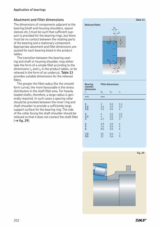
Fig. 29
Abutment and fillet dimensionsThe dimensions of components adjacent to the bearing (shaft and housing shoulders, spacer sleeves etc.) must be such that sufficient support is provided for the bearing rings, but there must be no contact between the rotating parts of the bearing and a stationary component. Appropriate abutment and fillet dimensions are quoted for each bearing listed in the product tables.
The transition between the bearing seating and shaft or housing shoulder, may either take the form of a simple fillet according to the dimensions ra and rb in the product tables, or be relieved in the form of an undercut. Table 13 provides suitable dimensions for the relieved fillets.
The greater the fillet radius (for the smooth form curve), the more favourable is the stress distribution in the shaft fillet area. For heavily loaded shafts, therefore, a large radius is generally required. In such cases a spacing collar should be provided between the inner ring and shaft shoulder to provide a sufficiently large support surface for the bearing ring. The side of the collar facing the shaft shoulder should be relieved so that it does not contact the shaft fillet († fig. 29).
Application of bearings
1 2 0,2 1,31,1 2,4 0,3 1,51,5 3,2 0,4 2 2 4 0,5 2,52,1 4 0,5 2,53 4,7 0,5 3 4 5,9 0,5 45 7,4 0,6 56 8,6 0,6 6 7,5 10 0,6 79,5 12 0,6 9
Table 13
Relieved fillets
Bearing Fillet dimensionschamferdimensionrs ba ha rc
mm mm
202

Fig. 30CARB toroidal roller bearingsCARB bearings can accommodate axial expansion of the shaft, within the bearing. To be sure that these axial displacements of the shaft with respect to the housing can take place it is necessary to provide space on both sides of the bearing († fig. 30).
Additional information can be found in the section “CARB toroidal roller bearings”, starting on page 779.
203
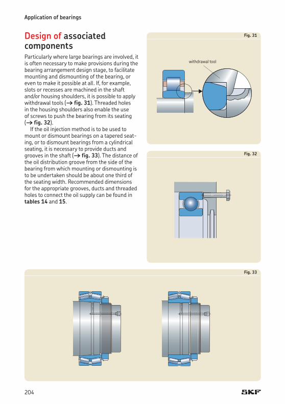
Design of associated componentsParticularly where large bearings are involved, it is often necessary to make provisions during the bearing arrangement design stage, to facilitate mounting and dismounting of the bearing, or even to make it possible at all. If, for example, slots or recesses are machined in the shaft and/or housing shoulders, it is possible to apply withdrawal tools († fig. 31). Threaded holes in the housing shoulders also enable the use of screws to push the bearing from its seating († fig. 32).
If the oil injection method is to be used to mount or dismount bearings on a tapered seating, or to dismount bearings from a cylindrical seating, it is necessary to provide ducts and grooves in the shaft († fig. 33). The distance of the oil distribution groove from the side of the bearing from which mounting or dismounting is to be undertaken should be about one third of the seating width. Recommended dimensions for the appropriate grooves, ducts and threaded holes to connect the oil supply can be found in tables 14 and 15.
Fig. 32
Application of bearings
Fig. 33
Fig. 31
withdrawal tool
204
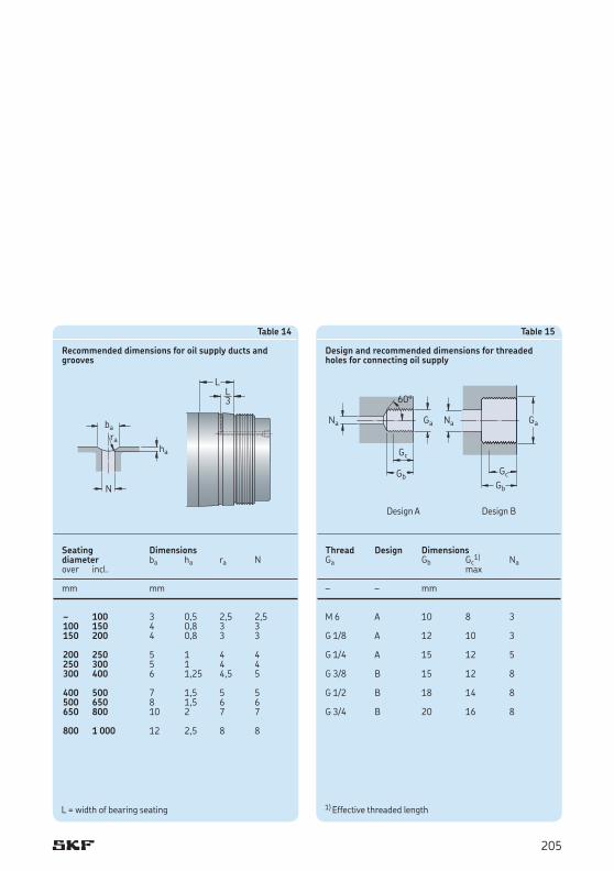
M 6 A 10 8 3
G 1/8 A 12 10 3
G 1/4 A 15 12 5
G 3/8 B 15 12 8
G 1/2 B 18 14 8
G 3/4 B 20 16 8
1) Effective threaded length
Table 15
Design and recommended dimensions for threaded holes for connecting oil supply
Thread Design DimensionsGa Gb Gc
1) Na max
– – mm
100 3 0,5 2,5 2,5100 150 4 0,8 3 3150 200 4 0,8 3 3 200 250 5 1 4 4250 300 5 1 4 4300 400 6 1,25 4,5 5 400 500 7 1,5 5 5500 650 8 1,5 6 6650 800 10 2 7 7 800 1 000 12 2,5 8 8
L = width of bearing seating
Table 14
Recommended dimensions for oil supply ducts and grooves
Seating Dimensionsdiameter ba ha ra Nover incl.
mm mm
–
Design BDesign A
205
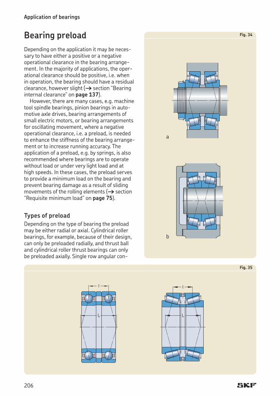
Bearing preloadDepending on the application it may be necessary to have either a positive or a negative operational clearance in the bearing arrangement. In the majority of applications, the operational clearance should be positive, i.e. when in operation, the bearing should have a residual clearance, however slight († section “Bearing internal clearance” on page 137).
However, there are many cases, e.g. machine tool spindle bearings, pinion bearings in automotive axle drives, bearing arrangements of small electric motors, or bearing arrangements for oscillating movement, where a negative operational clearance, i.e. a preload, is needed to enhance the stiffness of the bearing arrangement or to increase running accuracy. The application of a preload, e.g. by springs, is also recommended where bearings are to operate without load or under very light load and at high speeds. In these cases, the preload serves to provide a minimum load on the bearing and prevent bearing damage as a result of sliding movements of the rolling elements († section “Requisite minimum load” on page 75).
Types of preloadDepending on the type of bearing the preload may be either radial or axial. Cylindrical roller bearings, for example, because of their design, can only be preloaded radially, and thrust ball and cylindrical roller thrust bearings can only be preloaded axially. Single row angular con
Application of bearings
Fig. 35
Fig. 34
a
b
206

tact ball bearings and taper roller bearings († fig. 34), which are normally subjected to axial preload, are generally mounted together with a second bearing of the same type in a backtoback (a) or facetoface (b) arrangement. Deep groove ball bearings are also generally preloaded axially, to do so, the bearings should have a greater radial internal clearance than Normal (e.g. C3) so that, as with angular contact ball bearings, a contact angle which is greater than zero will be produced.
For both taper roller and angular contact ball bearings, the distance L between the pressure centres is longer when the bearings are arranged backtoback († fig. 35) and shorter when they are arranged facetoface († fig. 36) than the distance l between the bearing centres. This means that bearings arranged backtoback can accommodate relatively large tilting moments even if the distance between the bearing centres is relatively short. The radial forces resulting from the moment load and the deformation caused by these in the bearings are smaller than for bearings arranged facetoface.
If in operation the shaft becomes warmer than the housing, the preload which was adjusted (set) at ambient temperature during mounting will increase, the increase being greater for facetoface than for backtoback arrangements. In both cases the thermal expansion in the radial direction serves to reduce clearance or increase preload. This tendency is increased by the thermal expansion in the axial direction when the bearings are facetoface, but is
reduced for backtoback arrangements. For backtoback arrangements only, for a given distance between the bearings and when the coefficient of thermal expansion is the same for the bearings and associated components, the radial and axial thermal expansions will cancel each other out so that the preload will not change.
Fig. 36
207

Effects of bearing preloadThe main reasons to apply bearing preload are to
• enhance stiffness• reduce running noise• enhance the accuracy of shaft guidance• compensate for wear and settling (bedding
down) processes in operation• provide long service life.
High stiffnessBearing stiffness (in kN/mm) is defined as the ratio of the force acting on the bearing to the elastic deformation in the bearing. The elastic deformation caused by a load in preloaded bearings is smaller for a given load range than in bearings which are not preloaded.
Quiet runningThe smaller the operational clearance in a bearing, the better the guidance of the rolling elements in the unloaded zone and the quieter the bearing in operation.
Accurate shaft guidancePreloaded bearings provide more accurate shaft guidance because preload restricts the ability of the shaft to deflect under load. For example, the more accurate guidance and the increased stiffness afforded by preloaded pinion and differential bearings means that the gear mesh will be kept accurate and remain constant, and that additional dynamic forces will be minimized. As a result, operation will be quiet and the gear mesh will have a long service life.
Compensating for wear and settlingWear and settling processes in a bearing arrangement during operation increase the clearance but this can be compensated for by preload.
Long service lifeIn certain applications preloaded bearing arrangements can enhance operational reliability and increase service life. A properly dimensioned preload can have a favourable influence on the load distribution in the bearings and therefore on service life († section “Maintaining the correct preload” on page 216).
Determining preload forcePreload may be expressed as a force or as a path (distance), although the preload force is the primary specification factor. Depending on the adjustment method, preload is also indirectly related to the frictional moment in the bearing.
Empirical values for the optimum preload can be obtained from proven designs and can be applied to similar designs. For new designs SKF recommends calculating the preload force and checking its accuracy by testing. As generally not all influencing factors of the actual operation are accurately known, corrections may be necessary in practice. The reliability of the calculation depends above all on how well the assumptions made regarding the temperature conditions in operation and the elastic behaviour of the associated components – most importantly the housing – coincide with the actual conditions.
When determining the preload, the preload force required to give an optimum combination of stiffness, bearing life and operational reliability should be calculated first. Then calculate the preload force to be used when adjusting the bearings during mounting. When mounting, the bearings should be at ambient temperature and not subjected to an operating load.
The appropriate preload at normal operating temperature depends on the bearing load. An angular contact ball bearing or a taper roller bearing can accommodate radial and axial loads simultaneously. Under radial load, a force acting in the axial direction will be produced in the bearing, and this must generally be accommodated by a second bearing, which faces in the opposite direction to the first one. Purely radial displacement of one bearing ring in relation to the other will mean that half of the bearing circumference (i.e. half of the rolling elements) is under load and the axial force produced in the bearing will be
Fa = R Fr for single row angular contact ball bearings or
Fa = 0,5 Fr/Y for single row taper roller bearings
where Fr is the radial bearing load († fig. 37).The values of the variable R which takes into
account the contact conditions inside angular contact ball bearings has to be determined according to the guidelines provided in the section “Determining axial force for bearings
Application of bearings
208

mounted singly or paired in tandem”, starting on page 415.
The values of the axial factor Y for taper roller bearings can be found in the product tables.
When a single bearing is subjected to a radial load Fr, an external axial force Fa of the above magnitude must be applied if the prerequisite for the basic load ratings (half of the bearing circumference under load) is to be fulfilled. If the applied external force is smaller, the number of rolling elements supporting the load will be smaller and the load carrying capacity of the bearing will be correspondingly reduced.
In a bearing arrangement comprising two single row angular contact ball bearings or two taper roller bearings backtoback or facetoface, each bearing must accommodate the axial forces from the other. When the two bearings are the same, the radial load acts centrally between the bearings and if the bearing arrangement is adjusted to zero clearance, the load distribution where half of the rolling elements are under load will be automatically achieved. In other load cases, particularly where there is an external axial load, it may be necessary to preload the bearings to compensate for the play produced as a result of the elastic deformation of the bearing taking the axial load into account and to achieve a more favourable load distribution in the other bearing, which is unloaded axially.
Preloading also increases the stiffness of the bearing arrangement. When considering stiffness it should be remembered that it is not only influenced by the resilience of the bearings, but also by the elasticity of the shaft and housing, the fits with which the rings are mounted and the elastic deformation of all other components in the force field including the abutments. These all have a considerable impact on the resilience of the total shaft system. The axial and radial resilience of a bearing depend on its internal design, i.e. on the contact conditions (point or line contact), the number and diameter of the rolling elements and the contact angle; the greater the contact angle, the greater the stiffness of the bearing in the axial direction.
Fig. 37
209

If, as a first approximation, a linear dependence of the resilience on the load is assumed, i.e. a constant spring ratio, then a comparison shows that the axial displacement in a bearing arrangement under preload is smaller than for a bearing arrangement without preload for the same external axial force Ka († diagram 2). A pinion bearing arrangement, for example, consists of two taper roller bearings A and B of different size having the spring constants cA and cB and is subjected to a preload force F0. If the axial force Ka acts on bearing A, bearing B will be unloaded, and the additional load acting on bearing A and the axial displacement da will be smaller than for a bearing without preload. However, if the external axial force exceeds the value
q cA wKa = F0 1 + —– < cB z
then bearing B will be relieved of the axial preload force and the axial displacement under additional load will be the same as it is for a bearing arrangement without preload, i.e. determined solely by the spring constant of bearing A. To prevent complete unloading of bearing B when bearing A is subjected to load Ka, the following preload force will thus be required
cBF0 = Ka ––––––– cA + cB
The forces and elastic displacements in a preloaded bearing arrangement as well as the effects of a change in preload force are most easily recognized from a preload force/preload path diagram († diagram 3). This consists of the spring curves of the components that are adjusted against each other to preload and enables the following
• the relationship of the preload force and preload path within the preloaded bearing arrangement
• the relationship between an externally applied axial force Ka and the bearing load for a preloaded bearing arrangement, as well as the elastic deformation produced by the external force.
In the diagram 3, all the components subjected to additional loads by the operational forces are represented by the curves that increase from left to right, and all the unloaded components by the curves that increase from right to left. Curves 1, 2 and 3 are for different preload forces (F01, F02 < F01 and F03 = 0). The broken lines refer to the bearings themselves whereas the unbroken lines are for the bearing position in total (bearing with associated components).
Using diagram 3 it is possible to explain the relationships, for example, for a pinion bearing arrangement († fig. 39, page 213) where bearing A is adjusted against bearing B via the shaft and housing to give preload. The external axial force Ka (axial component of tooth forces) is superimposed on the preload force F01 (curve 1) in such a way that bearing A is subjected to additional load while bearing B is unloaded. The load at bearing position A is designated FaA, that at bearing position B, FaB.
Under the influence of the force Ka, the pinion shaft is axially displaced by the amount da1. The smaller preload force F02 (curve 2) has been chosen so that bearing B is just unloaded by the axial force Ka, i.e. FaB = 0 and FaA = Ka. The pinion shaft is displaced in this case by the amount da2 > da1. When the arrangement is not preloaded (curve 3) the axial displacement of the pinion shaft is at its greatest (da3 > da2).
Application of bearings
210

Diagram 2
Axial displacement da
Without preload
External axial force Ka With preload F0
Diagram 3
Axial displacement da
Axial force FaPreload force F0
Bearing B
Bearing A
Bearing position A (total)Bearing position B (total)
211

Adjustment proceduresAdjustment means setting the bearing internal clearance († section “Mounting”, starting on page 261) or setting the preload of a bearing arrangement.
The radial preload usually used for cylindrical roller bearings, double row angular contact ball bearings and sometimes for deep groove ball bearings, for example, is achieved by using a sufficient degree of interference for one or both of the bearing rings to reduce the initial internal clearance of the bearing to zero so that in operation there will be a negative clearance, i.e. preload.
Bearings with a tapered bore are particularly suitable for radial preloading since, by driving the bearing up on to its tapered seating, the preload can be applied to within narrow limits.
Axial preload in single row angular contact ball bearings, taper roller bearings and also deep groove ball bearings is produced by displacing one bearing ring axially in relation to the other by an amount corresponding to the desired preload force. There are two main groups of adjustment methods that differ in the principle on which they are based: individual adjustment and collective adjustment.
Individual adjustmentWith individual adjustment, each bearing arrangement is adjusted separately using nuts, shims, spacer sleeves, deformable sleeves etc. Measuring and inspection procedures provide that the established nominal preload force is obtained with the least possible deviation. There are different methods depending on the quantity of bearings to be measured
• adjustment using preload path• adjustment using friction torque• adjustment using direct force measurement.
Individual adjustment has the advantage that individual components can be produced to Normal tolerances and the desired preload can be achieved with a reasonably high degree of accuracy.
Adjustment using preload pathThis method of adjustment is frequently used when the components of a bearing arrangement are preassembled. The preload is achieved, for example, for a pinion bearing arrangement by
• fitting intermediate rings between the outer and inner rings of the two bearings († fig. 38)
• inserting shims between a housing shoulder and a bearing outer ring or between the casing and the housing († fig. 39), the housing in this case is the flanged angled insert
• fitting a spacer ring between a shaft shoulder and one of the bearing inner rings († fig. 40) or between the inner rings of the two bearings.
Application of bearings
212

Fig. 38
Fig. 39
Fig. 40
213

The width of the shims, intermediate rings or spacer rings is determined by
• the distance between the shaft and housing shoulders
• the total width of both bearings• the preload path (axial displacement) corres
ponding to the desired preload force• a correction factor for the preload path to
account for thermal expansion in operation• the manufacturing tolerances of all related
components, established by measuring the actual dimensions before mounting
• a correction factor to account for a certain loss of preload force after a certain period of operation.
This method of adjustment is based on the relationship between the preload force and the elastic deformations within the preloaded system. The requisite preload can be determined from a preload force/preload path diagram († diagram 4).
50.11 – Tint plate. Body copy
Diagram 4
Preload path d
F0© preload force on the pinion shaft (bearing arrangement)
d01 preload path for the pinion head bearing and surrounding components
d02 preload path for the bearing at the flange side and surrounding components
d0 total preload path for pinion bearing arrangement
Preload force F0
Application of bearings
214
Adjustment using the frictional momentThis method is popular in series production because of the short time required and because considerable automation is possible. Since there is a definite relationship between bearing preload and the frictional moment in the bearing, it is possible to stop adjustment when a frictional moment corresponding to the desired preload has been reached if the frictional moment is continuously monitored. However, it should be remembered that the frictional moment can vary from bearing to bearing, and that it also depends on the preservative used, or on the lubrication conditions and the speed.
Adjustment using direct force measurementAs the purpose of bearing adjustment is to produce a given preload in the bearings, it would seem sensible to use a method either to produce the force directly, or to measure the force directly. However, in practice the indirect methods of adjustment by preload path or friction torque are preferred as they are simple and can be achieved easily and more cost efficiently.
Collective adjustmentWith this method of adjustment, which may also be termed “random statistical adjustment”, the bearings, shaft and housing, spacer rings or sleeves etc. are produced in normal quantities and randomly assembled, the components being fully interchangeable. Where taper roller bearings are concerned, this interchangeability also extends to the outer rings and inner ring assemblies. In order not to have to resort to the uneconomic production of very accurate bearings and associated components, it is assumed that the limiting values of the tolerances – statistically – seldom occur together. If, however, the preload force is to be obtained with as little scatter as possible, manufacturing tolerances must be reduced. The advantage of collective adjustment is that no inspection is required and no extra equipment needed when mounting the bearings.
215
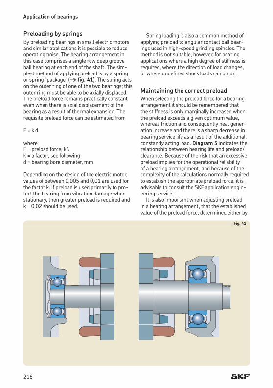
Fig. 41
Preloading by springsBy preloading bearings in small electric motors and similar applications it is possible to reduce operating noise. The bearing arrangement in this case comprises a single row deep groove ball bearing at each end of the shaft. The simplest method of applying preload is by a spring or spring “package” († fig. 41). The spring acts on the outer ring of one of the two bearings; this outer ring must be able to be axially displaced. The preload force remains practically constant even when there is axial displacement of the bearing as a result of thermal expansion. The requisite preload force can be estimated from
F = k d
whereF = preload force, kNk = a factor, see followingd = bearing bore diameter, mm
Depending on the design of the electric motor, values of between 0,005 and 0,01 are used for the factor k. If preload is used primarily to protect the bearing from vibration damage when stationary, then greater preload is required and k = 0,02 should be used.
Spring loading is also a common method of applying preload to angular contact ball bearings used in highspeed grinding spindles. The method is not suitable, however, for bearing applications where a high degree of stiffness is required, where the direction of load changes, or where undefined shock loads can occur.
Maintaining the correct preloadWhen selecting the preload force for a bearing arrangement it should be remembered that the stiffness is only marginally increased when the preload exceeds a given optimum value, whereas friction and consequently heat generation increase and there is a sharp decrease in bearing service life as a result of the additional, constantly acting load. Diagram 5 indicates the relationship between bearing life and preload/clearance. Because of the risk that an excessive preload implies for the operational reliability of a bearing arrangement, and because of the complexity of the calculations normally required to establish the appropriate preload force, it is advisable to consult the SKF application engineering service.
It is also important when adjusting preload in a bearing arrangement, that the established value of the preload force, determined either by
Application of bearings
216
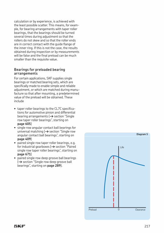
Diagram 5
Life
Preload Clearance
calculation or by experience, is achieved with the least possible scatter. This means, for example, for bearing arrangements with taper roller bearings, that the bearings should be turned several times during adjustment so that the rollers do not skew and so that the roller ends are in correct contact with the guide flange of the inner ring. If this is not the case, the results obtained during inspection or by measurements will be false and the final preload can be much smaller than the requisite value.
Bearings for preloaded bearing arrangementsFor certain applications, SKF supplies single bearings or matched bearing sets, which are specifically made to enable simple and reliable adjustment, or which are matched during manufacture so that after mounting, a predetermined value of the preload will be obtained. These include
• taper roller bearings to the CL7C specifications for automotive pinion and differential bearing arrangements († section “Single row taper roller bearings”, starting on page 605)
• single row angular contact ball bearings for universal matching († section “Single row angular contact ball bearings”, starting on page 409)
• paired single row taper roller bearings, e.g. for industrial gearboxes († section “Paired single row taper roller bearings”, starting on page 671)
• paired single row deep groove ball bearings († section “Single row deep groove ball bearings”, starting on page 289).
217
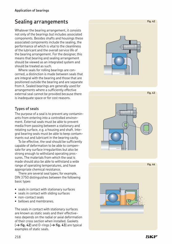
Fig. 42
Fig. 43
Fig. 44
Sealing arrangementsWhatever the bearing arrangement, it consists not only of the bearings but includes associated components. Besides shafts and housings these associated components include the sealing, the performance of which is vital to the cleanliness of the lubricant and the overall service life of the bearing arrangement. For the designer, this means that bearing and sealing arrangement should be viewed as an integrated system and should be treated as such.
Where seals for rolling bearings are concerned, a distinction is made between seals that are integral with the bearing and those that are positioned outside the bearing and are separate from it. Sealed bearings are generally used for arrangements where a sufficiently effective external seal cannot be provided because there is inadequate space or for cost reasons.
Types of sealsThe purpose of a seal is to prevent any contaminants from entering into a controlled environment. External seals must be able to prevent media from passing between a stationary and rotating surface, e.g. a housing and shaft. Integral bearing seals must be able to keep contaminants out and lubricant in the bearing cavity.
To be effective, the seal should be sufficiently capable of deformation to be able to compensate for any surface irregularities but also be strong enough to withstand operating pressures. The materials from which the seal is made should also be able to withstand a wide range of operating temperatures, and have appropriate chemical resistance.
There are several seal types; for example, DIN 3750 distinguishes between the following basic types
• seals in contact with stationary surfaces• seals in contact with sliding surfaces• noncontact seals• bellows and membranes.
The seals in contact with stationary surfaces are known as static seals and their effectiveness depends on the radial or axial deformation of their cross section when installed. Gaskets († fig. 42) and Orings († fig. 43) are typical examples of static seals.
Application of bearings
218
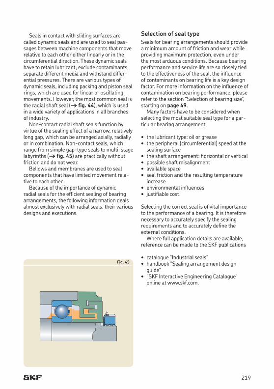
Fig. 45
Seals in contact with sliding surfaces are called dynamic seals and are used to seal passages between machine components that move relative to each other either linearly or in the circumferential direction. These dynamic seals have to retain lubricant, exclude contaminants, separate different media and withstand differential pressures. There are various types of dynamic seals, including packing and piston seal rings, which are used for linear or oscillating movements. However, the most common seal is the radial shaft seal († fig. 44), which is used in a wide variety of applications in all branches of industry.
Noncontact radial shaft seals function by virtue of the sealing effect of a narrow, relatively long gap, which can be arranged axially, radially or in combination. Noncontact seals, which range from simple gaptype seals to multistage labyrinths († fig. 45) are practically without friction and do not wear.
Bellows and membranes are used to seal components that have limited movement relative to each other.
Because of the importance of dynamic radial seals for the efficient sealing of bearing arrangements, the following information deals almost exclusively with radial seals, their various designs and executions.
Selection of seal typeSeals for bearing arrangements should provide a minimum amount of friction and wear while providing maximum protection, even under the most arduous conditions. Because bearing performance and service life are so closely tied to the effectiveness of the seal, the influence of contaminants on bearing life is a key design factor. For more information on the influence of contamination on bearing performance, please refer to the section “Selection of bearing size”, starting on page 49.
Many factors have to be considered when selecting the most suitable seal type for a particular bearing arrangement
• the lubricant type: oil or grease• the peripheral (circumferential) speed at the
sealing surface• the shaft arrangement: horizontal or vertical• possible shaft misalignment• available space• seal friction and the resulting temperature
increase• environmental influences• justifiable cost.
Selecting the correct seal is of vital importance to the performance of a bearing. It is therefore necessary to accurately specify the sealing requirements and to accurately define the external conditions.
Where full application details are available, reference can be made to the SKF publications
• catalogue “Industrial seals”• handbook “Sealing arrangement design
guide”• “SKF Interactive Engineering Catalogue”
online at www.skf.com.
219
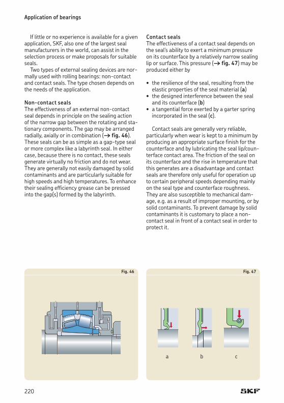
If little or no experience is available for a given application, SKF, also one of the largest seal manufacturers in the world, can assist in the selection process or make proposals for suitable seals.
Two types of external sealing devices are normally used with rolling bearings: noncontact and contact seals. The type chosen depends on the needs of the application.
Non-contact sealsThe effectiveness of an external noncontact seal depends in principle on the sealing action of the narrow gap between the rotating and stationary components. The gap may be arranged radially, axially or in combination († fig. 46). These seals can be as simple as a gaptype seal or more complex like a labyrinth seal. In either case, because there is no contact, these seals generate virtually no friction and do not wear. They are generally not easily damaged by solid contaminants and are particularly suitable for high speeds and high temperatures. To enhance their sealing efficiency grease can be pressed into the gap(s) formed by the labyrinth.
Contact sealsThe effectiveness of a contact seal depends on the seal’s ability to exert a minimum pressure on its counterface by a relatively narrow sealing lip or surface. This pressure († fig. 47) may be produced either by
• the resilience of the seal, resulting from the elastic properties of the seal material (a)
• the designed interference between the seal and its counterface (b)
• a tangential force exerted by a garter spring incorporated in the seal (c).
Contact seals are generally very reliable, particularly when wear is kept to a minimum by producing an appropriate surface finish for the counterface and by lubricating the seal lip/counterface contact area. The friction of the seal on its counterface and the rise in temperature that this generates are a disadvantage and contact seals are therefore only useful for operation up to certain peripheral speeds depending mainly on the seal type and counterface roughness. They are also susceptible to mechanical damage, e.g. as a result of improper mounting, or by solid contaminants. To prevent damage by solid contaminants it is customary to place a noncontact seal in front of a contact seal in order to protect it.
Fig. 46
Application of bearings
Fig. 47
a b c
220
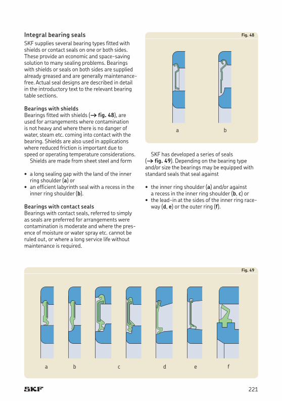
Integral bearing sealsSKF supplies several bearing types fitted with shields or contact seals on one or both sides. These provide an economic and spacesaving solution to many sealing problems. Bearings with shields or seals on both sides are supplied already greased and are generally maintenance free. Actual seal designs are described in detail in the introductory text to the relevant bearing table sections.
Bearings with shieldsBearings fitted with shields († fig. 48), are used for arrangements where contamination is not heavy and where there is no danger of water, steam etc. coming into contact with the bearing. Shields are also used in applications where reduced friction is important due to speed or operating temperature considerations.
Shields are made from sheet steel and form
• a long sealing gap with the land of the inner ring shoulder (a) or
• an efficient labyrinth seal with a recess in the inner ring shoulder (b).
Bearings with contact sealsBearings with contact seals, referred to simply as seals are preferred for arrangements were contamination is moderate and where the presence of moisture or water spray etc. cannot be ruled out, or where a long service life without maintenance is required.
SKF has developed a series of seals († fig. 49). Depending on the bearing type and/or size the bearings may be equipped with standard seals that seal against
• the inner ring shoulder (a) and/or against a recess in the inner ring shoulder (b, c) or
• the leadin at the sides of the inner ring raceway (d, e) or the outer ring (f).
Fig. 48
a b
Fig. 49
a b c d e f
221

For deep groove ball bearings SKF has developed two additional seal types († fig. 50), referred to as
• the lowfriction seal (a, b, c), which is practically without contact and fulfils high demands on sealing and the lowfriction operation of the bearing
• the springloaded radial shaft Waveseal® (d), which is incorporated on one side and together with the bearing, form the ICOS oil sealed bearing unit.
Seals integrated in SKF bearings are generally made of elastomer materials and reinforced by sheet steel. Depending on the series, size and the application requirements, the seals are generally produced from
• acrylonitrilebutadiene rubber (NBR)• hydrogenated acrylonitrilebutadiene rubber
(HNBR)• fluoro rubber (FKM)• polyurethane (AU).
The selection of the appropriate seal material depends on the expected operating temperature and the applied lubricant. Concerning the permissible operating temperatures, please refer to the section “Seal materials”, starting on page 142.
Application of bearings
Fig. 50
a b c d
222
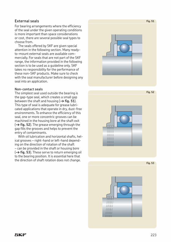
External sealsFor bearing arrangements where the efficiency of the seal under the given operating conditions is more important than space considerations or cost, there are several possible seal types to choose from.
The seals offered by SKF are given special attention in the following section. Many readytomount external seals are available commercially. For seals that are not part of the SKF range, the information provided in the following section is to be used as a guideline only. SKF takes no responsibility for the performance of these nonSKF products. Make sure to check with the seal manufacturer before designing any seal into an application.
Non-contact sealsThe simplest seal used outside the bearing is the gaptype seal, which creates a small gap between the shaft and housing († fig. 51). This type of seal is adequate for grease lubricated applications that operate in dry, dustfree environments. To enhance the efficiency of this seal, one or more concentric grooves can be machined in the housing bore at the shaft exit († fig. 52). The grease emerging through the gap fills the grooves and helps to prevent the entry of contaminants.
With oil lubrication and horizontal shafts, helical grooves – righthand or lefthand depending on the direction of rotation of the shaft – can be provided in the shaft or housing bore († fig. 53). These serve to return emerging oil to the bearing position. It is essential here that the direction of shaft rotation does not change.
Fig. 51
Fig. 52
Fig. 53
223
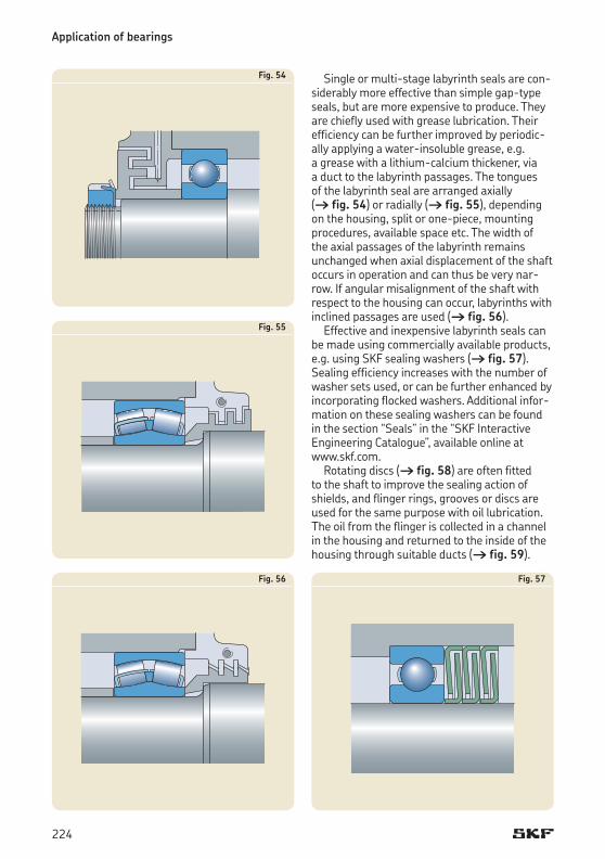
Single or multistage labyrinth seals are considerably more effective than simple gaptype seals, but are more expensive to produce. They are chiefly used with grease lubrication. Their efficiency can be further improved by periodically applying a waterinsoluble grease, e.g. a grease with a lithiumcalcium thickener, via a duct to the labyrinth passages. The tongues of the labyrinth seal are arranged axially († fig. 54) or radially († fig. 55), depending on the housing, split or onepiece, mounting procedures, available space etc. The width of the axial passages of the labyrinth remains unchanged when axial displacement of the shaft occurs in operation and can thus be very narrow. If angular misalignment of the shaft with respect to the housing can occur, labyrinths with inclined passages are used († fig. 56).
Effective and inexpensive labyrinth seals can be made using commercially available products, e.g. using SKF sealing washers († fig. 57). Sealing efficiency increases with the number of washer sets used, or can be further enhanced by incorporating flocked washers. Additional information on these sealing washers can be found in the section “Seals” in the “SKF Interactive Engineering Catalogue”, available online at www.skf.com.
Rotating discs († fig. 58) are often fitted to the shaft to improve the sealing action of shields, and flinger rings, grooves or discs are used for the same purpose with oil lubrication. The oil from the flinger is collected in a channel in the housing and returned to the inside of the housing through suitable ducts († fig. 59).
Fig. 54
Fig. 55
Fig. 56 Fig. 57
Application of bearings
224

Fig. 61
Fig. 60
Fig. 59Contact sealsRadial shaft seals are contact seals that are used, above all, for sealing oillubricated bearing arrangements. These readytomount elastomer sealing components normally have a metal reinforcement or casing. The sealing lip is usually a synthetic rubber and is normally pressed against a counterface on the shaft by a garter spring. Depending on the seal material and medium to be retained and/or excluded, radial shaft seals can be used at temperatures between –60 and +190 °C.
The contact area between the sealing lip and counterface is of vital importance to sealing efficiency. The surface hardness of the counterface should normally be at least 55 HRC and the hardened depth should be at least 0,3 mm, the surface roughness to ISO 4288:1996 should be within the guidelines of Ra = 0,2 to 0,8 mm. In applications, where speeds are low, lubrication is good and contamination is minimal, a lower hardness can be acceptable. To avoid the pumping action produced by helical grinding marks, plunge grinding is recommended.
If the main purpose of the radial shaft seal is to prevent lubricant from leaving the housing, the seal should be mounted with the lip facing inwards († fig. 60). If the main purpose is to exclude contaminants, the lip should face outwards, away from the bearing († fig. 61).
Fig. 58
225

Vring seals († fig. 62) can be used both with oil and with grease lubrication. The elastic rubber ring (body) of the seal firmly grips the shaft and rotates with it, while the sealing lip exerts a light axial pressure on the stationary component, e.g. the housing. Depending on the material, Vrings can be used at operating temperatures between –40 and +150 °C. They are simple to install and at low speeds permit relatively large angular misalignments of the shaft. A surface roughness Ra of between 2 and 3 mm is sufficient for the counterface. At peripheral speeds above 8 m/s the Vring must be axially located on the shaft. At speeds above 12 m/s the ring must be prevented from “lifting” from the shaft by, for example, a sheet metal support ring. When the peripheral speed exceeds 15 m/s the sealing lip will lift from the counterface so that the Vring becomes a gaptype seal. The good sealing action of the Vring depends mainly on the fact that the ring body acts as a flinger, repelling dirt and fluids. Therefore, with grease lubrication the seal is generally arranged outside the housing, whereas for oil lubrication it is normally arranged inside the housing with the lip pointing away from the bearing position. Used as a secondary seal, Vrings protect the primary seal from excessive contaminants and moisture.
Axial clamp seals († fig. 63) are used as secondary seals for large diameter shafts in applications where protection is required for the primary seal. They are clamped in position on a nonrotating component and seal axially against a rotating counterface. For this type of seal, it is sufficient if the counterface is fine turned and has a surface roughness Ra of 2,5 mm.
Mechanical seals († fig. 64) are used to seal grease or oil lubricated bearing positions where speeds are relatively low and operating conditions difficult and arduous. They consist of two sliding steel rings with finely finished sealing surfaces and two plastic cup springs (Belleville washers), which position the sliding rings in the housing bore and provide the necessary preload force to the sealing surfaces. There are no special demands on the mating surfaces in the housing bore.
Fig. 64
Fig. 63
Fig. 62
Application of bearings
226
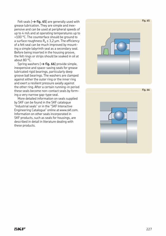
Felt seals († fig. 65) are generally used with grease lubrication. They are simple and inexpensive and can be used at peripheral speeds of up to 4 m/s and at operating temperatures up to +100 °C. The counterface should be ground to a surface roughness Ra ≤ 3,2 mm. The efficiency of a felt seal can be much improved by mounting a simple labyrinth seal as a secondary seal. Before being inserted in the housing groove, the felt rings or strips should be soaked in oil at about 80 °C.
Spring washers († fig. 66) provide simple, inexpensive and spacesaving seals for grease lubricated rigid bearings, particularly deep groove ball bearings. The washers are clamped against either the outer ring or the inner ring and exert a resilient pressure axially against the other ring. After a certain runningin period these seals become noncontact seals by forming a very narrow gaptype seal.
More detailed information on seals supplied by SKF can be found in the SKF catalogue “Industrial seals” or in the “SKF Interactive Engineering Catalogue” online at www.skf.com. Information on other seals incorporated in SKF products, such as seals for housings, are described in detail in literature dealing with these products.
Fig. 66
Fig. 65
227