6 Martindale Commutator Grinding and Turning Tools · The Martindale Commutator Grinder assures...
2
6 MARTINDALE • PO Box 430 • Cleveland, OH 44107 Phone (216) 521-8567 • Fax Local 521-9476 / USA & Canada (800) 344-9191 E-Mail: [email protected] Web Site: www.martindaleco.com 04/05 Martindale Commutator Grinding and Turning Tools Available in 2 styles in lengths from 6” to 48”. Will grind, with commstones, 1” beyond base at each end or turn, with turning tool, 2” less than base length at each end. At left: Turning Tool Head Fig. 5 At left and at right: With Grinding Head FIG. 1 STRAIGHT: Used where there are no obstructions to interfere with crossfeed handle. FIG. 8 RIGHT ANGLE: Used where end frame, fan, etc., would interfere with crossfeed handle of Fig. 1. Grinders: (Carrying Case included with grinders below) Catalog Number Commutator Grinding Tool (Fig. 1), w/ 10” base or less . . . . . . . . . . . . . . . . . . . . . . . . . . . . . . . . . . . . . . . . . . . . .GRDR300* Commutator Turning Tool (Fig. 1), w/ 10” base or less, with Fig. 5 Head instead of Grinding Head . . . . . . . . . . . . . . . . . . . . . . . . . . . . . . . . . . . . . . . . . . . . . . . . . . . .GRDR301* Right-Angle Grinding Tool (Fig. 8), w/ 10” base or less . . . . . . . . . . . . . . . . . . . . . . . . . . . . . . . . . . . . . . . . . . . . . .GRDR400* Right-Angle Turning Tool (Fig. 8), w/ 10” base or less, with Fig. 5 Head instead of Grinding Head . . . . . . . . . . . . . . . . . . . . . . . . . . . . . . . . . . . . . . . . . . . . . . . . . . . .GRDR401* For Grinders 10” to 26”: add per inch over 10” . . . . . . . . . . . . . . . . . . . . . . . . . . . . . . . . . . . . . . . . . . . . . . . . . . . .GRDR666 (Grinder prices 28” and over on application.) *Add base length to P/N when ordering (i.e.: “10”, 12”, etc.) Power-Drive and Accessories, 115 V., 60 Hz. (See Page 7 for Description) . . . . . . . . . . . . . . . . . . . . . . . . . . . . .GRDR501A 230 V., 50 Hz. (See Page 7 for Description) . . . . . . . . . . . . . . . . . . . . . . . . . . . . .GRDR501B Turning Tool Head (Fig. 5), including Tool Holder . . . . . . . . . . . . . . . . . . . . . . . . . . . . . . . . . . . . . . . . . . . . . . . . . .GRDR505 Supports: Fig. 2 “L” Support (See Page 7 for Description) . . . . . . . . . . . . . . . . . . . . . . . . . . . . . . . . . . . . . . . . . . . . . . . .GRDR50202 Fig. 6 Wedge Block (See Page 7 for Description) . . . . . . . . . . . . . . . . . . . . . . . . . . . . . . . . . . . . . . . . . . . . . . .GRDR50206 Fig. 9 “T” Support (See Page 7 for Description) . . . . . . . . . . . . . . . . . . . . . . . . . . . . . . . . . . . . . . . . . . . . . . . .GRDR50209 Extension Handles (Fig. 7): 6” (See Page 7 for Description) . . . . . . . . . . . . . . . . . . . . . . . . . . . . . . . . . . . . . . . . . . . . . . . . . . . . . . . . . . . .GRDR50306 10” (See Page 7 for Description) . . . . . . . . . . . . . . . . . . . . . . . . . . . . . . . . . . . . . . . . . . . . . . . . . . . . . . . . . . . .GRDR50310 Commstones for above: 2” x 2” x 8” Plain Lathe Type . . . . . . . . . . . . . . . . . . . . . . . . . . . . . . . . . . . . . . . . . . . . . . . . . . . . . . . . . . . . . . . . . .COMMXLS855** **When ordering, specify cat. no. and grade (i.e. EC, C, M, F, P) (See Commstone descriptions in Diamond D Abrasives Catalog — pages 4, 5 & 7) The Martindale Commutator Grinder assures concentricity of the commutator or slip-ring by precision grinding while it is turn- ing in its own bearings at operating speeds and temperatures, with centrifugal force holding each bar in place. Either tool (Fig. 1 or 8) can be quickly changed from right to left hand operation. On Fig. 1, remove two screws and turn the cross-slide around. On Fig. 8, the right-angle driving shaft is removed and inserted in the other side of the right-angle housing, and the grinding head cross-slide turned around as with Fig. 1. When grinding use 2” x 2” x 8” Commstones in any of the 5 grades shown and described in Diamond D Catalog — pages 4, 5 & 7. The stones will grind 1” beyond the grinder base at each end, and they can be cocked to get into the corner at the riser. If very deep grooves must be removed, the Fig. 5 Turning Tool Head may be used. It is interchangeable with the Grinding Head on either Fig. 1 or Fig. 8. The tool holder should be positioned as indicated in the upper left corner of this page. The top of the commutator should rotate away from the operator so that if the mounting should slip, the tool bit would be pushed away from the commutator instead of digging in. It is necessary to add 4” to the grinder base length when using the Turning Tool. Weights: Figs. 1 or 8 with 12” base, Net 29 lbs., Shipping 38 lbs.; add about 2 lbs. for each additional inch. Power- Drive unit, Net 27 lbs., Shipping 32 lbs. See Power-Drive and Supports for Commutator Grinders - Page 7
Transcript of 6 Martindale Commutator Grinding and Turning Tools · The Martindale Commutator Grinder assures...
6
MARTINDALE • PO Box 430 • Cleveland, OH 44107Phone (216) 521-8567 • Fax Local 521-9476 / USA & Canada (800) 344-9191E-Mail: [email protected] Site: www.martindaleco.com 04/05
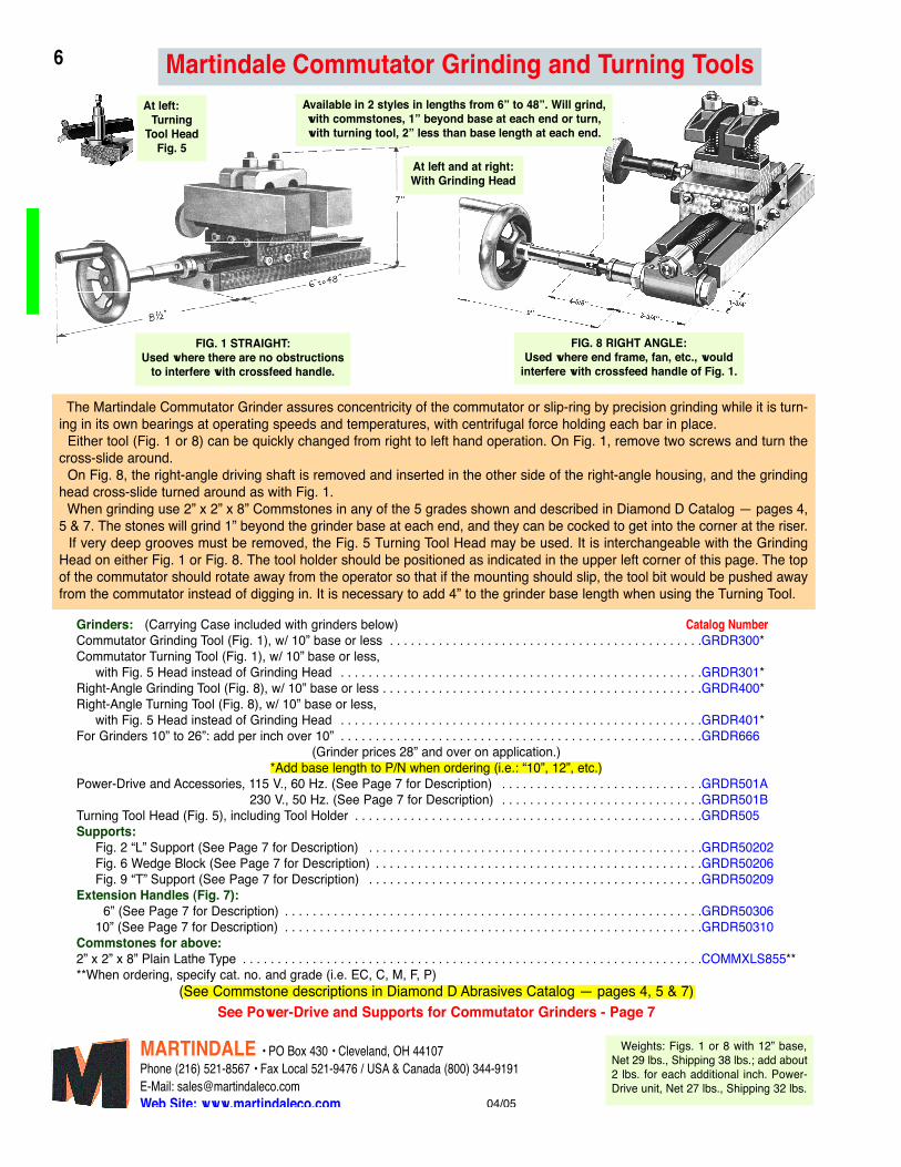
Martindale Commutator Grinding and Turning ToolsAvailable in 2 styles in lengths from 6” to 48”. Will grind,with commstones, 1” beyond base at each end or turn,with turning tool, 2” less than base length at each end.
At left:Turning
Tool HeadFig. 5
At left and at right:With Grinding Head
FIG. 1 STRAIGHT:Used where there are no obstructions
to interfere with crossfeed handle.
FIG. 8 RIGHT ANGLE:Used where end frame, fan, etc., would
interfere with crossfeed handle of Fig. 1.
Grinders: (Carrying Case included with grinders below) Catalog NumberCommutator Grinding Tool (Fig. 1), w/ 10” base or less . . . . . . . . . . . . . . . . . . . . . . . . . . . . . . . . . . . . . . . . . . . . .GRDR300*Commutator Turning Tool (Fig. 1), w/ 10” base or less,
with Fig. 5 Head instead of Grinding Head . . . . . . . . . . . . . . . . . . . . . . . . . . . . . . . . . . . . . . . . . . . . . . . . . . . .GRDR301*Right-Angle Grinding Tool (Fig. 8), w/ 10” base or less . . . . . . . . . . . . . . . . . . . . . . . . . . . . . . . . . . . . . . . . . . . . . .GRDR400*Right-Angle Turning Tool (Fig. 8), w/ 10” base or less,
with Fig. 5 Head instead of Grinding Head . . . . . . . . . . . . . . . . . . . . . . . . . . . . . . . . . . . . . . . . . . . . . . . . . . . .GRDR401*For Grinders 10” to 26”: add per inch over 10” . . . . . . . . . . . . . . . . . . . . . . . . . . . . . . . . . . . . . . . . . . . . . . . . . . . .GRDR666
(Grinder prices 28” and over on application.)*Add base length to P/N when ordering (i.e.: “10”, 12”, etc.)
Power-Drive and Accessories, 115 V., 60 Hz. (See Page 7 for Description) . . . . . . . . . . . . . . . . . . . . . . . . . . . . .GRDR501A230 V., 50 Hz. (See Page 7 for Description) . . . . . . . . . . . . . . . . . . . . . . . . . . . . .GRDR501B
Turning Tool Head (Fig. 5), including Tool Holder . . . . . . . . . . . . . . . . . . . . . . . . . . . . . . . . . . . . . . . . . . . . . . . . . .GRDR505Supports:
Fig. 2 “L” Support (See Page 7 for Description) . . . . . . . . . . . . . . . . . . . . . . . . . . . . . . . . . . . . . . . . . . . . . . . .GRDR50202Fig. 6 Wedge Block (See Page 7 for Description) . . . . . . . . . . . . . . . . . . . . . . . . . . . . . . . . . . . . . . . . . . . . . . .GRDR50206Fig. 9 “T” Support (See Page 7 for Description) . . . . . . . . . . . . . . . . . . . . . . . . . . . . . . . . . . . . . . . . . . . . . . . .GRDR50209
Extension Handles (Fig. 7):6” (See Page 7 for Description) . . . . . . . . . . . . . . . . . . . . . . . . . . . . . . . . . . . . . . . . . . . . . . . . . . . . . . . . . . . .GRDR50306
10” (See Page 7 for Description) . . . . . . . . . . . . . . . . . . . . . . . . . . . . . . . . . . . . . . . . . . . . . . . . . . . . . . . . . . . .GRDR50310Commstones for above:2” x 2” x 8” Plain Lathe Type . . . . . . . . . . . . . . . . . . . . . . . . . . . . . . . . . . . . . . . . . . . . . . . . . . . . . . . . . . . . . . . . . .COMMXLS855****When ordering, specify cat. no. and grade (i.e. EC, C, M, F, P)
(See Commstone descriptions in Diamond D Abrasives Catalog — pages 4, 5 & 7)
The Martindale Commutator Grinder assures concentricity of the commutator or slip-ring by precision grinding while it is turn-ing in its own bearings at operating speeds and temperatures, with centrifugal force holding each bar in place.
Either tool (Fig. 1 or 8) can be quickly changed from right to left hand operation. On Fig. 1, remove two screws and turn thecross-slide around.
On Fig. 8, the right-angle driving shaft is removed and inserted in the other side of the right-angle housing, and the grindinghead cross-slide turned around as with Fig. 1.
When grinding use 2” x 2” x 8” Commstones in any of the 5 grades shown and described in Diamond D Catalog — pages 4,5 & 7. The stones will grind 1” beyond the grinder base at each end, and they can be cocked to get into the corner at the riser.
If very deep grooves must be removed, the Fig. 5 Turning Tool Head may be used. It is interchangeable with the GrindingHead on either Fig. 1 or Fig. 8. The tool holder should be positioned as indicated in the upper left corner of this page. The topof the commutator should rotate away from the operator so that if the mounting should slip, the tool bit would be pushed awayfrom the commutator instead of digging in. It is necessary to add 4” to the grinder base length when using the Turning Tool.
Weights: Figs. 1 or 8 with 12” base,Net 29 lbs., Shipping 38 lbs.; add about2 lbs. for each additional inch. Power-Drive unit, Net 27 lbs., Shipping 32 lbs.
See Power-Drive and Supports for Commutator Grinders - Page 7
7
MARTINDALE • PO Box 430 • Cleveland, OH 44107Phone (216) 521-8567 • Fax Local 521-9476 / USA & Canada (800) 344-9191E-Mail: [email protected] Site: www.martindaleco.com 04/05
Fig. 9“T”
Support
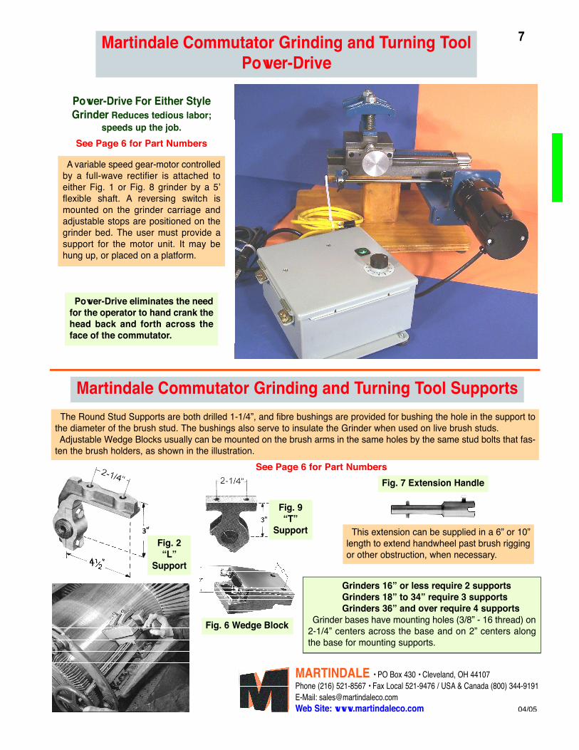
Power-Drive eliminates the needfor the operator to hand crank thehead back and forth across theface of the commutator.
A variable speed gear-motor controlledby a full-wave rectifier is attached toeither Fig. 1 or Fig. 8 grinder by a 5’flexible shaft. A reversing switch ismounted on the grinder carriage andadjustable stops are positioned on thegrinder bed. The user must provide asupport for the motor unit. It may behung up, or placed on a platform.
The Round Stud Supports are both drilled 1-1/4”, and fibre bushings are provided for bushing the hole in the support tothe diameter of the brush stud. The bushings also serve to insulate the Grinder when used on live brush studs.Adjustable Wedge Blocks usually can be mounted on the brush arms in the same holes by the same stud bolts that fas-
ten the brush holders, as shown in the illustration.
Grinders 16” or less require 2 supportsGrinders 18” to 34” require 3 supportsGrinders 36” and over require 4 supports
Grinder bases have mounting holes (3/8” - 16 thread) on2-1/4” centers across the base and on 2” centers alongthe base for mounting supports.
Fig. 7 Extension Handle
This extension can be supplied in a 6” or 10”length to extend handwheel past brush riggingor other obstruction, when necessary.
Power-Drive For Either StyleGrinder Reduces tedious labor;
speeds up the job.
Martindale Commutator Grinding and Turning ToolPower-Drive
Martindale Commutator Grinding and Turning Tool Supports
Fig. 6 Wedge Block
See Page 6 for Part Numbers
See Page 6 for Part Numbers
Fig. 2“L”
Support


![[The, Commutator] vol.3 issue 1](https://static.fdocuments.net/doc/165x107/568c4c691a28ab4916a00e3d/the-commutator-vol3-issue-1.jpg)