
6. Electrical - Ijeee- Smart Epilepsy Detection - Sukumar
10
www.iaset.us [email protected] SMART EPILEPSY DETECTION SUKUMAR T R 1 , BHARATH KUMAR M R 2 , ANDREW MATHEW DOMNIC F 3 , SIBU C M 4 & KARTHIKEYEN V 5 1,2,3,4 UG Student, Nehru Institute of Engineering & Technology, Coimbatore, Tamil Nadu, India 5 Assistant Professor, Nehru Institute of Engineering & Technology, Coimbatore, Tamil Nadu, India ABSTRACT In this proposed system along with the prototype presented here is a wearable device which predicts the occurrence of epilepsy in advance. The device utilizes the signals from human homosapien to detect the occurrence of epilepsy. As soon as the device detects the signals generated from the host and it transmits an encoded signal. The signal is decoded by a wireless receiver to produce signals to trigger alarm device, and mobile messaging device control system appropriately. The prototype is made for verification and to determine the performance of the system. KEYWORDS: Smart Epilepsy, Detects the Symptoms, Wireless Receiver, Mobile Messaging, Decode INTRODUCTION Epilepsy is a very fatal condition which is caused as a result of imbalance in the nervous system. The very common symptoms of epilepsy includes sudden fluctuations in heart beat rate and involuntary muscular movements (seizures). The aura (practical symptom) of epilepsy includes fluctuations in heartbeat, nausea, dizziness etc. The wireless electronic diagnosing system designed here is exclusively meant for epilepsy patients. The system helps them in accurately predicting the occurrence of seizures. Sudden occurrence of seizures during driving may lead to accidents and its occurrence during sleeping hours can even lead to the patient’s death, if no immediate, proper attention is provided by a bystander or a doctor. With the aid of this system, the patient can lead a normal life. Since the occurrence of seizures is unpredictable, it will be a very risky task to leave the patient alone. In future, GPS could be incorporated to trace out the exact location of the patient. Current technologies for acquiring signals from the patient’s body are very much developed. Many sensors are available which can detect the heart beat and muscular movements non-invasively and accurately. Such non invasive technique for measuring heart beat is pulse oximetry. Using this technique, heart beat can be accurately monitored. Muscular convulsions are collected using micro electromechanical sensors (MEMS) firmly attached to the body. The sensors used are small in size and can be firmly attached to the body. The accelerations resulting from epileptic convulsions are sensed using MEMS accelerometer which is very accurate, precise and small in size. To provide wireless communication channel low cost network using MiWi protocol is utilized. MiWi is a standard protocol developed by Microchip Inc, USA, based on IEEE 802.15.4. Heart beats are to be monitored continuously. Any sudden variation in heart beat which is caused by the onset of epileptic seizures is detected and confirmed with the MEMS signal. When the seizure is confirmed, message is transmitted to the surroundings for initiating necessary protective measures for the patient. The device is designed as wireless, wearable and personal equipment. Hence a technician’s assistance is not required for the patient. Therefore this device will International Journal of Electrical and Electronics Engineering (IJEEE) ISSN(P): 2278-9944; ISSN(E): 2278-9952 Vol. 3, Issue 3, May 2014, 49-58 © IASET
Transcript of 6. Electrical - Ijeee- Smart Epilepsy Detection - Sukumar
www.iaset.us [email protected]
SMART EPILEPSY DETECTION
SUKUMAR T R1, BHARATH KUMAR M R 2, ANDREW MATHEW DOMNIC F 3, SIBU C M4
& KARTHIKEYEN V 5 1,2,3,4UG Student, Nehru Institute of Engineering & Technology, Coimbatore, Tamil Nadu, India
5Assistant Professor, Nehru Institute of Engineering & Technology, Coimbatore, Tamil Nadu, India
ABSTRACT
In this proposed system along with the prototype presented here is a wearable device which predicts the
occurrence of epilepsy in advance. The device utilizes the signals from human homosapien to detect the occurrence of
epilepsy. As soon as the device detects the signals generated from the host and it transmits an encoded signal. The signal is
decoded by a wireless receiver to produce signals to trigger alarm device, and mobile messaging device control system
appropriately. The prototype is made for verification and to determine the performance of the system.
KEYWORDS: Smart Epilepsy, Detects the Symptoms, Wireless Receiver, Mobile Messaging, Decode
INTRODUCTION
Epilepsy is a very fatal condition which is caused as a result of imbalance in the nervous system. The very
common symptoms of epilepsy includes sudden fluctuations in heart beat rate and involuntary muscular movements
(seizures). The aura (practical symptom) of epilepsy includes fluctuations in heartbeat, nausea, dizziness etc. The wireless
electronic diagnosing system designed here is exclusively meant for epilepsy patients. The system helps them in accurately
predicting the occurrence of seizures. Sudden occurrence of seizures during driving may lead to accidents and its
occurrence during sleeping hours can even lead to the patient’s death, if no immediate, proper attention is provided by a
bystander or a doctor. With the aid of this system, the patient can lead a normal life. Since the occurrence of seizures is
unpredictable, it will be a very risky task to leave the patient alone. In future, GPS could be incorporated to trace out the
exact location of the patient. Current technologies for acquiring signals from the patient’s body are very much developed.
Many sensors are available which can detect the heart beat and muscular movements non-invasively and accurately.
Such non invasive technique for measuring heart beat is pulse oximetry. Using this technique, heart beat can be
accurately monitored. Muscular convulsions are collected using micro electromechanical sensors (MEMS) firmly attached
to the body. The sensors used are small in size and can be firmly attached to the body. The accelerations resulting from
epileptic convulsions are sensed using MEMS accelerometer which is very accurate, precise and small in size.
To provide wireless communication channel low cost network using MiWi protocol is utilized. MiWi is a standard
protocol developed by Microchip Inc, USA, based on IEEE 802.15.4.
Heart beats are to be monitored continuously. Any sudden variation in heart beat which is caused by the onset of
epileptic seizures is detected and confirmed with the MEMS signal. When the seizure is confirmed, message is transmitted
to the surroundings for initiating necessary protective measures for the patient. The device is designed as wireless,
wearable and personal equipment. Hence a technician’s assistance is not required for the patient. Therefore this device will
International Journal of Electrical and Electronics Engineering (IJEEE) ISSN(P): 2278-9944; ISSN(E): 2278-9952 Vol. 3, Issue 3, May 2014, 49-58 © IASET

50 Sukumar T R, Bharath Kumar M R, Andrew Mathew Domnic F, Sibu C M & Karthikeyen V
Impact Factor (JCC): 2.4886 Index Copernicus Value (ICV): 3.0
be extremely useful for patients (especially youngsters) who wish to be active in their life. The user gets absolute freedom
from wires and can be used when moving.
To practically implement the epilepsy prediction system, the following aspects should be implemented
• Sensing Biometric Signals: Two types of biological signals are required for processing. They are heart beat and
muscular convulsions. The heart beat can be measured using pulse oxy meter and muscular movements can be
measured using MEMS sensor.
• Processing it and Taking Decisions: Processing of the signals is done by software programmed into a
microcontroller. The software is designed in such a way that it detects the exact symptom of epilepsy.
• Communication: Communication is set up using a transmitter and receiver module with MiWi protocol
• Controlling: Automatic vehicle control system, mobile messaging device and an alarm device is integrated to the
receiver for protecting the patient.
CONSTRAINTS
• Smaller size and weight requirement
• Low power consumption requirement as the device is battery operated.
• Suitable long life battery
• Accurate technique or algorithm for foolproof detection of seizure
• Secure communication between the wearable equipment and the receiving unit
• Signal processing requirement
• Cost effectiveness
The application of this system focus on epilepsy patients who wish to move freely without the assistance of others
in their life. For instance, if the seizure occurs while the victim driving a vehicle or while sleeping the device automatically
generates control signals for the control of vehicle, setting off an alarm circuit and messaging the doctor about the patient’s
condition via short messaging Service (SMS). The system can be expanded easily in such a way to include Global
Positioning System (GPS) for tracing out the exact position of the victim of epilepsy in the future. Thus the device saves
the patient from accident or even death and acts as a “LIFE SAVER”
DESIGN
The design consists of hardware and software sections. The device hardware mainly consist of three parts namely,
• Heart beat sensor
• Seizure detector
• Processor and
• Wireless transceiver
Smart Epilepsy Detection 51
www.iaset.us [email protected]
Heart Beat Sensor
The heart beat of the patient is to be monitored accurately. For this purpose, a pulse oxy meter is used. Pulse oxy
meter measures heart beat by sensing the difference in absorbance of infrared radiation by blood during systolic and
diastolic activities of heart. The volume of blood flowing through arteries varies widely during each heart beat. Hence if
infrared radiation is incident on it, the absorbance of IR also varies according to the heart beat
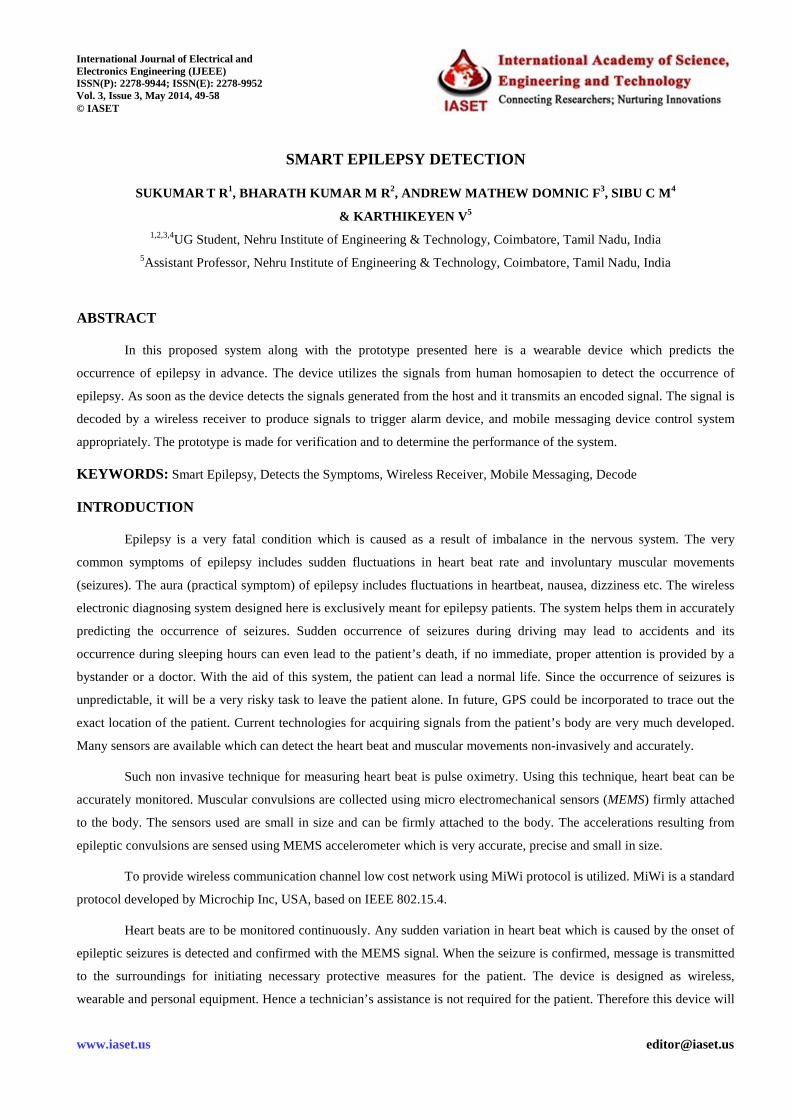
Figure 1: Pulse Oxy Meter and its Principle of Operation
The pulse oxy meter designed here works using reflective principle. The IR source emits IR radiation which is
reflected in accordance with the flow of blood. The reflected rays are detected using a photo detector.
A sensor is placed on a thin part of the patient's anatomy, usually a fingertip or earlobe, and light of infrared
wavelength is made incident on the body. Changing absorbance of the infrared is measured, allowing determination of the
absorbance’s due to the pulsing arterial blood alone, excluding venous blood, skin, bone, muscle, fat, and (in most cases)
fingernail polish. The circuit of pulse oxy meter consists of a trans-resistance amplifier, voltage follower, difference
amplifier, and filter. All these stages are cascaded together to from the complete circuit of pulse oxy meter. The circuit
works in 5 V supply. In order to get perfect amplification sans noise, ultra low offset operational amplifier OP07 and
FET input operational amplifier LF 356N is selected. A Trans resistance amplifier is used in the first stage to convert the
photodiode current to voltage. The major design parameter of this sensor is its output voltage and the output frequency.
The output frequency is band limited to 15 Hz using filters. Low pass first order butter worth filter is used. Low pass filter
is designed at 15 Hz upper cut off frequency with a gain of 1.5. A high pass first order butter worth filter with lower cut off
frequency of 0.5 Hz is cascaded with the low pass to remove the dc voltage. An amplifier is set at the output of the meter in
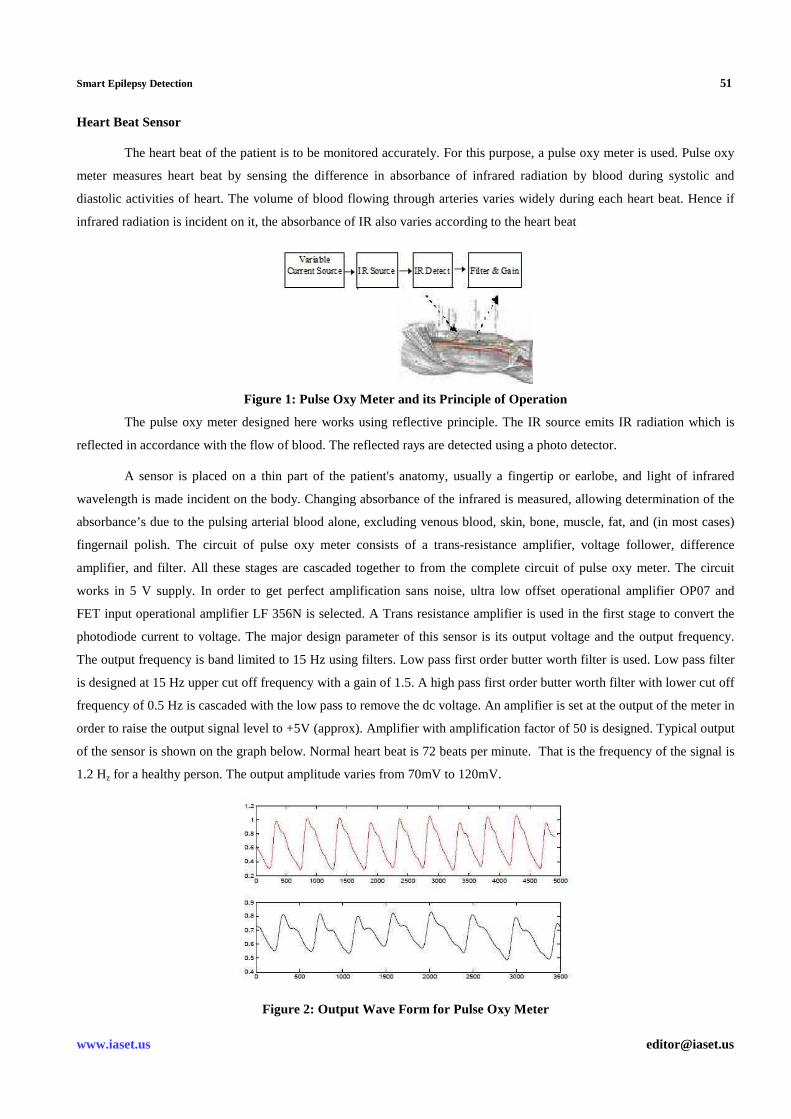
order to raise the output signal level to +5V (approx). Amplifier with amplification factor of 50 is designed. Typical output
of the sensor is shown on the graph below. Normal heart beat is 72 beats per minute. That is the frequency of the signal is
1.2 Hz for a healthy person. The output amplitude varies from 70mV to 120mV.
Figure 2: Output Wave Form for Pulse Oxy Meter

52 Sukumar T R, Bharath Kumar M R, Andrew Mathew Domnic F, Sibu C M & Karthikeyen V
Impact Factor (JCC): 2.4886 Index Copernicus Value (ICV): 3.0
• Seizure Detector
Seizures are involuntary muscular movements which occur during epilepsy. Muscular movements are sensed
using MEMS (micro electro mechanical sensor) accelerometer. A 3D accelerometer is used to sense the muscular
movements. The ADXL330 is a low cost, low power, complete 3-axis accelerometer with signal conditioned voltage
outputs, which is all on a single monolithic IC. The ADXL330 is a complete acceleration measurement system on a single
monolithic IC. The ADXL330 has a measurement range of ±5 g. The sensor is a polysilicon surface-micro machined
structure built on top of a silicon wafer. Polysilicon springs suspend the structure over the surface of the wafer and provide
a resistance against acceleration forces. Deflection of the structure is measured using a differential capacitor that consists
of independent fixed plates and plates attached to the moving mass. The fixed plates are driven by 180° out-of-phase
square waves. Acceleration deflects the beam and unbalances the differential capacitor, resulting in an output square wave
whose amplitude is proportional to acceleration. Phase-sensitive demodulation techniques are then used to rectify the
signal and determine the direction of the acceleration. The demodulator’s output is amplified and brought off-chip through
a 32 kΩ resistor. The signal bandwidth of the device is set by adding a capacitor. This filtering improves measurement
resolution and helps prevent aliasing.
Performance of the project was affected due to the non availability of 3 axis accelerometer. Hence here I have
used a single axis accelerometer MMA1260EG from FREESCALE semiconductor for detecting the muscular convulsions.
It has a sensitivity of 1.5g. The output is filtered using a n RC low pass filter with values R=1 KΩ ad C=0.10.1µf.
The output of the sensor during typical seizure is shown on the graph. The output of MEMS is given to a 10 bit analog to
digital converter for digitizing the output.
• Processor
The signals from sensors are processed using PIC18F4620 microcontroller. The microcontroller requires a 10 bit
ADC and a comparator circuit for processing the signals from the sensor. PIC 18F 4620 includes built in ADC and
comparator. The processor is clocked at 4MHz. The frequency of normal heart beat rate is 1.2 HZ. approximately. Or the
time period of the heart beat signal is 0.83 secs. The algorithm detects the sudden decrease in pulse width which is one of
the auras of epilepsy. As soon as the variations in the heart beat are detected, the algorithm checks for the typical seizure
waveform from the MEMS sensor. When these two signals coincide, the software takes the decision as an epileptic seizure
and generates control signals.
• Wireless Transceiver
The device uses MiWi protocol for communication. The MiWi™ Wireless Networking Protocol is a simple
protocol designed for low data rate, short distance, and low-cost networks. Fundamentally based on IEEE 802.15.4™ for
wireless personal area networks (WPANs), the MiWi protocol provides an easy-to-use alternative for wireless
communication. In particular, it targets smaller applications that have relatively small network sizes, with few hops
between nodes, using Microchip’s MRF24J40 2.4 GHz transceiver for IEEE 802.15.4 compliant networks. The MiWi
protocol is based on the MAC and PHY layers of the IEEE 802.15.4 specification, and is tailored for simple network
development in the 2.4 GHz band. The protocol provides the features to find form and join a network, as well as
discovering nodes on the network and route to them. The card uses PCB trace antenna. The device uses line of sight
communication. The range is approx. 200ft The wireless transmitter and receiver hardware consist of a motherboard with
Smart Epilepsy Detection 53
www.iaset.us [email protected]
PIC 18F4620 microcontroller. The motherboard consists of a daughter card with microchip MRF24J40 IEEE 802.15.4 2.4
GHZ transceiver. The board is designed to work at 9V to 3.3 V DC. The MiWi protocol stack can be installed on the board
and the required application can be programmed into it. A peer to peer network is formed using the transceivers.
One node is programmed as the network coordinator and the other as an end device. The coordinator is set as the
transmitter and the en device as the receiver. The long address is assigned for the network and the short address to the
nodes. The device is designed in such a way that it searches for a network as soon as the module is switched on.
The coordinator assigns the address to the end devices and forms the network if one is not detected. The MRF24J40 is an
IEEE 802.15.4-2003 compliant transceiver supporting MiWi™, ZigBee™ and other proprietary protocols. The MRF24J40
integrates wireless RF, PHY layer baseband and MAC layer architectures that can be combined with a simple
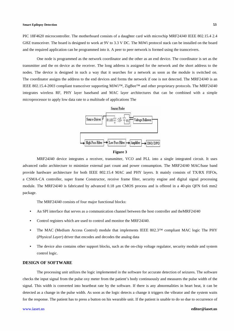
microprocessor to apply low data rate to a multitude of applications The
Figure 3
MRF24J40 device integrates a receiver, transmitter, VCO and PLL into a single integrated circuit. It uses
advanced radio architecture to minimize external part count and power consumption. The MRF24J40 MAC/base band
provide hardware architecture for both IEEE 802.15.4 MAC and PHY layers. It mainly consists of TX/RX FIFOs,
a CSMA-CA controller, super frame Constructor, receive frame filter, security engine and digital signal processing
module. The MRF24J40 is fabricated by advanced 0.18 µm CMOS process and is offered in a 40-pin QFN 6x6 mm2
package.
The MRF24J40 consists of four major functional blocks:
• An SPI interface that serves as a communication channel between the host controller and theMRF24J40
• Control registers which are used to control and monitor the MRF24J40.
• The MAC (Medium Access Control) module that implements IEEE 802.3™ compliant MAC logic The PHY
(Physical Layer) driver that encodes and decodes the analog data
• The device also contains other support blocks, such as the on-chip voltage regulator, security module and system
control logic.
DESIGN OF SOFTWARE
The processing unit utilizes the logic implemented in the software for accurate detection of seizures. The software
checks the input signal from the pulse oxy meter from the patient’s body continuously and measures the pulse width of the
signal. This width is converted into heartbeat rate by the software. If there is any abnormalities in heart beat, it can be
detected as a change in the pulse width. As soon as the logic detects a change it triggers the vibrator and the system waits
for the response. The patient has to press a button on his wearable unit. If the patient is unable to do so due to occurrence of
54 Sukumar T R, Bharath Kumar M R, Andrew Mathew Domnic F, Sibu C M & Karthikeyen V
Impact Factor (JCC): 2.4886 Index Copernicus Value (ICV): 3.0
seizure, then response signal from MEMS sensor which senses the muscular convulsions is captured and analyzed.
If there are signals of muscular convulsions the software concludes that the patient has seizure and warning message is
transmitted using the wireless transmitter. The seizure detection algorithm from the MEMS signals is to check only the
sudden abnormality occurring in the human body. This algorithm helps to avoid situations where heart beat rises due to
excessive physical work or due to tension etc. The algorithm uses the averaging technique to determine abnormalities
accurately.
P= (P+N)/2
Where p=previous heart beat rate N=next heart beat rate.
For a person suffering from epilepsy, in the pre octal stage the heart beat varies abruptly and hence the value of P
also changes. This change in the value of P is detected and the program is made to wait for the signal from the second
sensor which senses the muscular convulsions. If muscular convulsions are detected from the second sensor, it triggers the
transmitter on which transmits a coded signal which is received by the receiver. The software section contains the
following major functional modules:
• Heart beat rate calculations
• Seizure detection from MEMS signal
• Communication control
• Overall supervision
IMPLEMENTATION
The system requires a heart beat sensor, muscular convulsion sensor, a transmitter, receiver, mobile messaging
device, alarm device and automatic vehicle control system. All the above said parts are integrated together to a processor to
form the device.
The epilepsy prediction system can be practically implemented by incorporating the following components
• Heart Beat Sensor
A pulse oxy meter is used as a heart beat sensor.
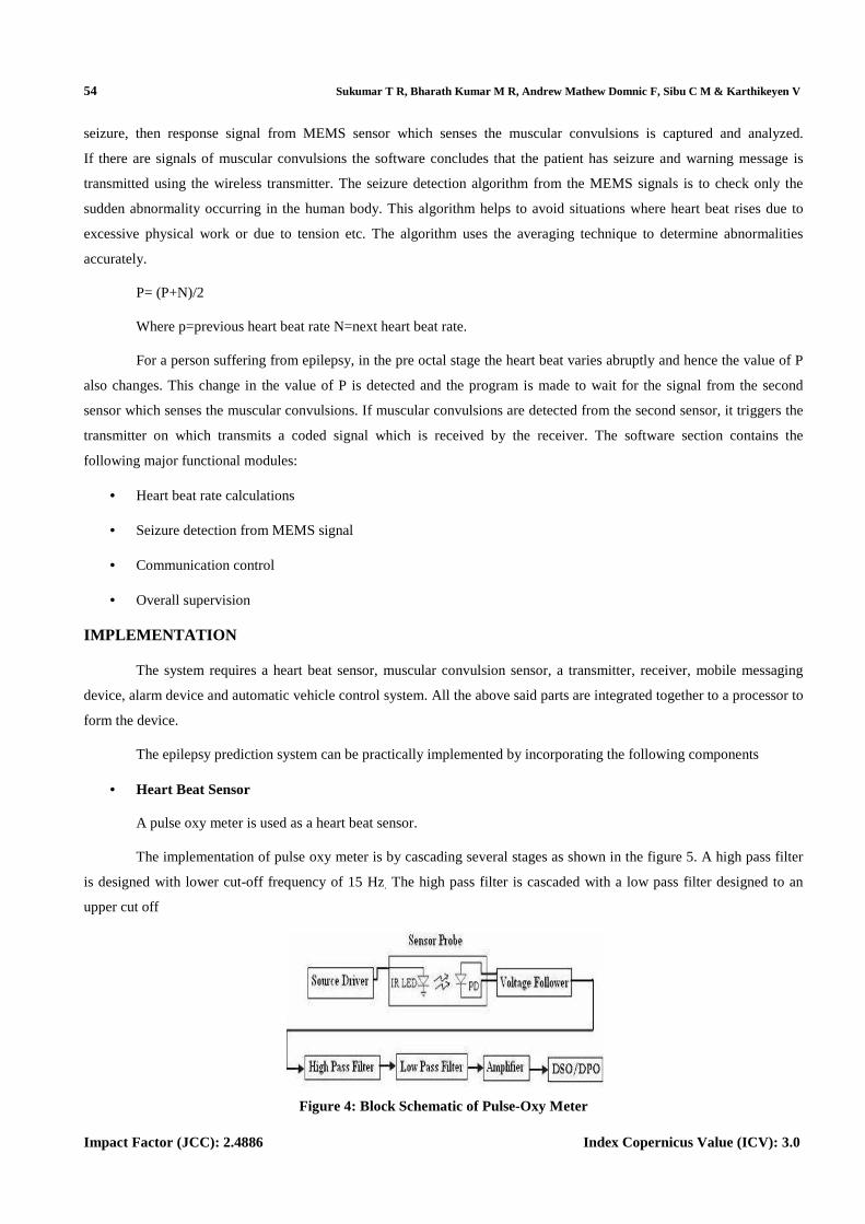
The implementation of pulse oxy meter is by cascading several stages as shown in the figure 5. A high pass filter
is designed with lower cut-off frequency of 15 Hz. The high pass filter is cascaded with a low pass filter designed to an
upper cut off
Figure 4: Block Schematic of Pulse-Oxy Meter

Smart Epilepsy Detection 55
www.iaset.us [email protected]
Frequency of 0.5 Hz The amplifier at the final stage raises the voltage from mV level to the required voltage
range. An amplification factor of 50 is given to it.
• Convulsions Sensor
An accelerometer is used as a convulsion sensor.
Figure 5: Block Diagram of the Convulsions Sensor
Muscular convulsions are detected using single axis MEMS IC MMA1260EG. The sensitivity of the sensor is set
to 1.55g. The circuit is implemented as shown in the circuit diagram. The output of the sensor is filtered out sing a low pass
RC filter externally. The value of R is selected as 1KΩ and C as 0.1µf.
• Processing Unit
The processing unit contains PIC 18F4620 microcontroller which is clocked at 40 MHz. PIC18F4620 have
64 Kbytes of Flash memory. The microcontroller has inbuilt 10 bit ADC which is used to digitize the output from MEMS
module. It also includes a comparator which is used to process the heart beat waveforms from the pulse oxy meter.
The incoming signal is processed using logics implemented in the software which runs the device. The processing unit
continuously checks for symptoms in the incoming signal. As soon as it detects any abnormality, it triggers a warning
vibrator and the wireless transmitter.
• Wireless Transmitter and Receiver
Wireless transceiver consist of a board consisting of MRF24J40 IC The transmitter transmits a coded signal which
is decoded by a receiver to generate control signals. The control signal activates an alarm device, mobile messaging device
and automatic vehicle control system appropriately. Apart from the above important blocks, a buzzer circuit and a DC to
DC convertor blocks are also implemented.
• Enclosure Design
The device is a wearable one (on the wrist). Hence the enclosure is designed suiting to that purpose. The enclosure
can be designed in the form of a watch.

56
Impact Factor (JCC): 2.4886
PHOTOGRAPHS
Figure
TESTING
• Testing of Pulse Oxy Meter
The pulse oxy meter was tested by wounding the probe of the device on the index finger of a person and the
output were viewed on a DSO. The pulse oxy meter successfully detected the heart beat waveform from the patient’s index
finger. The out put frequency was 1.2 H
• Testing of MEMS Sensor
The MEMS sensor is connected to the body of the patient using straps. Typical epileptic seizure waveform is
shown in the figure below. The sensor output is expected to be of the
Sukumar T R, Bharath Kumar M R, Andrew Mathew Domnic F, Sibu C M & Karthikeyen V
Index Copernicus Value (ICV): 3.0
Figure 6: Epilepsy Sensor, Transmitter and Receiver
Figure 7: Pulse Oxy Meter
r was tested by wounding the probe of the device on the index finger of a person and the
output were viewed on a DSO. The pulse oxy meter successfully detected the heart beat waveform from the patient’s index
finger. The out put frequency was 1.2 Hz. And the voltage level was in the range of 100 to 120 mV.
The MEMS sensor is connected to the body of the patient using straps. Typical epileptic seizure waveform is
shown in the figure below. The sensor output is expected to be of the shape as shown below.
Sukumar T R, Bharath Kumar M R, Andrew Mathew Domnic F, Sibu C M & Karthikeyen V
Index Copernicus Value (ICV): 3.0
r was tested by wounding the probe of the device on the index finger of a person and the
output were viewed on a DSO. The pulse oxy meter successfully detected the heart beat waveform from the patient’s index
the voltage level was in the range of 100 to 120 mV.
The MEMS sensor is connected to the body of the patient using straps. Typical epileptic seizure waveform is

Smart Epilepsy Detection 57
www.iaset.us [email protected]
Figure 8: Typical Signal from the MEMS Sensor during Seizure
• Testing of Software
The inputs from the sensors were provided to the PIC controller in which the software was programmed Wave
forms describing different conditions of the patient were given as input and tested successfully
• Testing of Communication Module
The transceiver is directly connected to the microcontroller in which the software was programmed. As soon as
the software detected the epileptic symptom, the transmitter was triggered. A peer to peer single node network was formed
which transmitted the message to the receiver node. The system designed here processes the heart beat continuously and
abnormalities are detected accurately. The device transmits the signal only when seizures of epilepsy are detected.
The performance of the device is not restricted by movement of the patient.
PROBLEMS ENCOUNTERED
We have encountered many problems as noted below:
• Non availability of 3 axis accelerometer: We could not procure the 3 axis accelerometer and hence testing is only
performed with a single axis accelerometer. However, the system gives better results only if a 3 axis
accelerometer is used in for detecting muscle contractions.
• Noise and temperature effect on the sensor outputs: Major problems were encountered due to noise picked up by
the sensors. Use of shielded cable and grounding solved the problems to a satisfactory level. Heating effect of
active components like op amps also created problems like drifting and thermal noise. This was solved by
operating the op amps at a lower voltage.
• Problem with suitable wearable enclosure: A suitable wearable enclosure is not designed. Compact PCB must be
designed to fit all the components inside a wearable enclosure.
ADVANTAGES AND BENEFITS
The benefit of the project is that a lightweight, rugged, low-cost, wearable (on the wrist) device is developed
which helps a victim of epilepsy to do all sorts of activities like others do.
• The device will be extremely cost effective since it uses simple sensors and technology for the detection.
• The sensors are small in size and can be firmly attached to the body
• Batteries can last long as the device consumes only little energy

58 Sukumar T R, Bharath Kumar M R, Andrew Mathew Domnic F, Sibu C M & Karthikeyen V
Impact Factor (JCC): 2.4886 Index Copernicus Value (ICV): 3.0
• The device doesn’t restrict the movement of the patient.
• The system is easily expandable paving the way to incorporate much more sophisticated devices like ECG
detector in the future
• Standalone application
CONCLUSIONS
A light weight, rugged, cost-effective wearable device is developed which helps millions of victims of epilepsy
around the globe. With the device in possession an epilepsy victim can move around freely like normal people sans
worries. The system is easily expandable to incorporate GPS system and to capture and transmit various patient parameters
like ECG, body temperature etc.
REFERENCES
1. Broadcast engineers reference book (by Joe Tozen Edwin Parll)
2. SMS 2003 (by Ron D Crumbaker)
3. Mobile technology (by Linda.W.Braun)
4. http://www.datasheet4u.com/html/M/M/A/MMA1260EG_F reescaleSemiconductor.pdf.html
5. http://www.microchip.com/downloads/en/DeviceDoc/39776a.pdf
6. http://www.microchip.com/downloads/en/AppNotes/0106 6a.pdf
7. http://www.microchip.com/downloads/en/DeviceDoc/515 24b.pdf
8. http://www.microchip.com/downloads/en/DeviceDoc/396 26d.pdf
9. http://www.nda.ox.ac.uk/wfsa/html/u05/u05_003.ht


![Jhalapala (Play) By Sukumar Ray - WordPress.com (Play) By Sukumar Ray [] Title: Jhalapala (Play) By Sukumar Ray Author: SM MASUD RANA Subject: Jhalapala (Play) By Sukumar Ray](https://static.fdocuments.net/doc/165x107/5ace09cc7f8b9a6c6c8b55ff/jhalapala-play-by-sukumar-ray-play-by-sukumar-ray-title-jhalapala-play.jpg)

