6-Bearing Capacity of Shallow Foundation
116
Bearing Capacity of Shallow Foundation
-
Upload
faris-ahmed-bhatti -
Category
Documents
-
view
48 -
download
11
description
6-Bearing Capacity of Shallow Foundation
Transcript of 6-Bearing Capacity of Shallow Foundation
Bearing Capacity of Shallow
Foundation
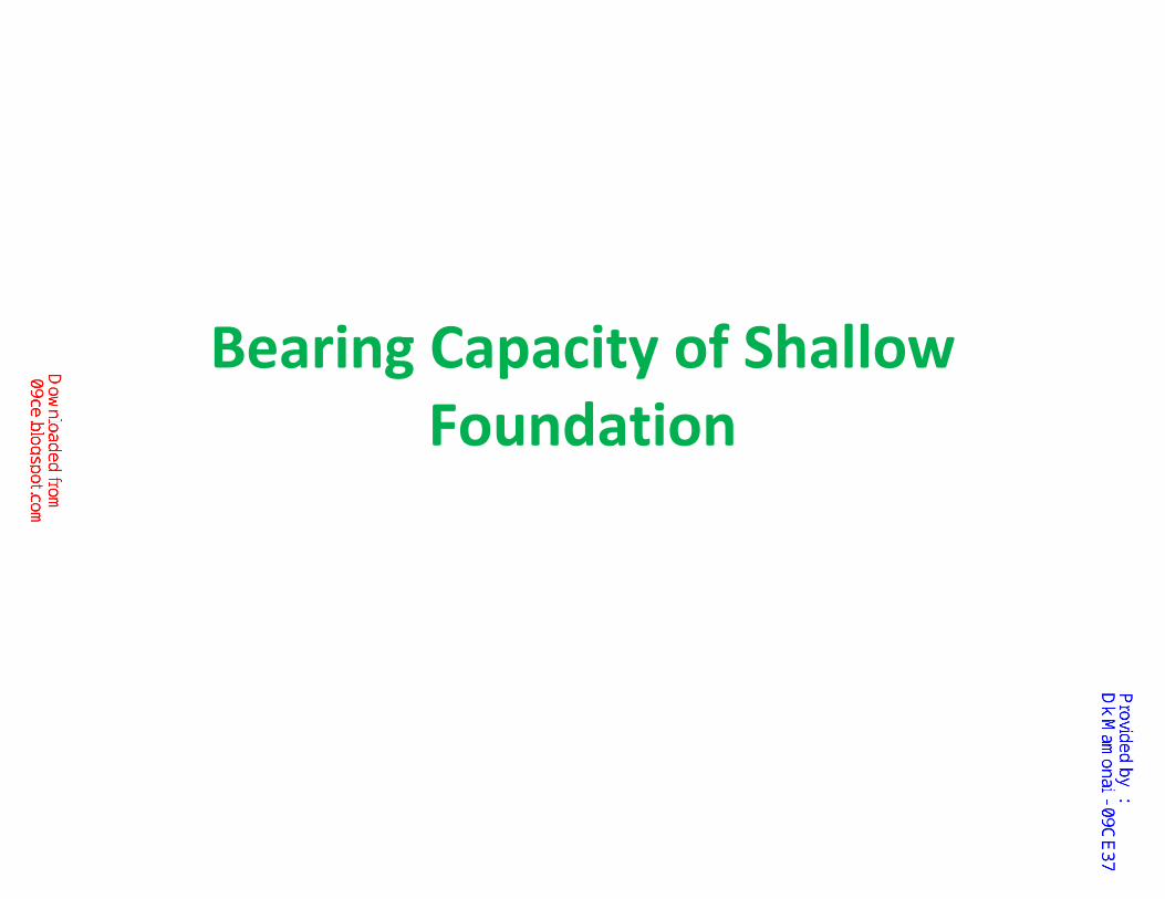
BEARING CAPACITY If a footing is subjected to too great a load,
some of the soil supporting it will reach a
failure state and the footing may experience a
bearing capacity failure.
The bearing capacity is the limiting pressure
that the footing can support.
Supporting soil
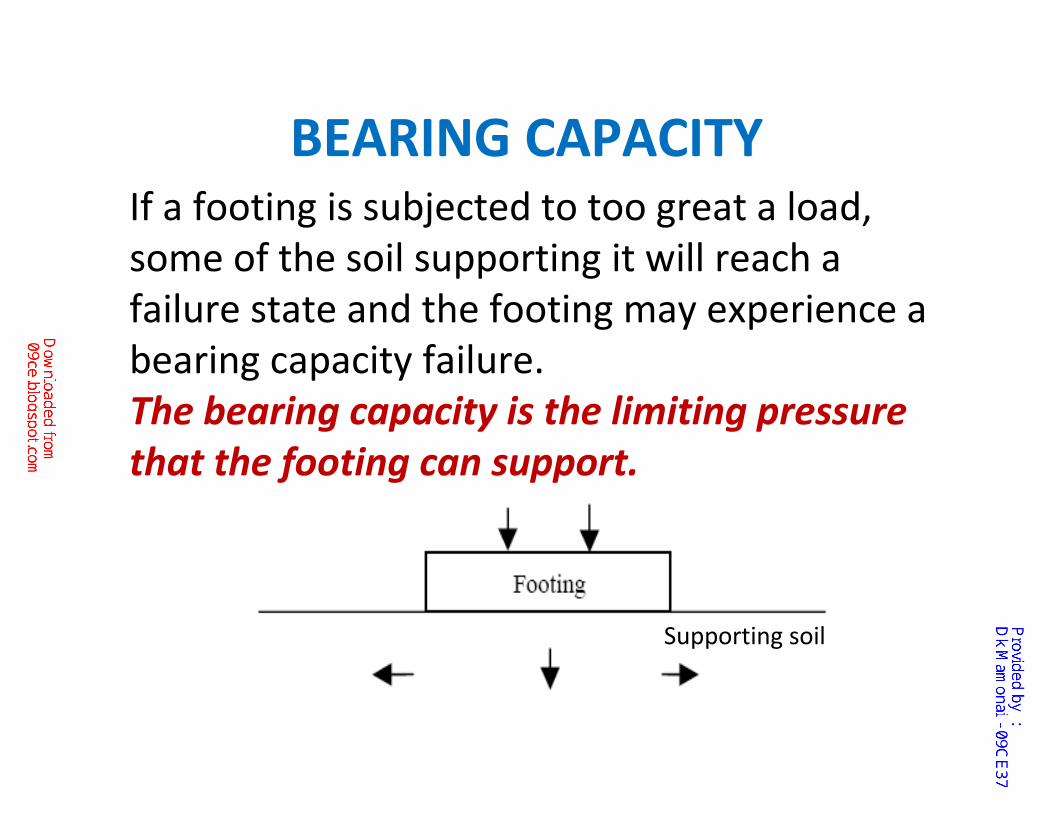
Foundation ?
A foundation is a structure that
transfers loads to the earth.
Foundations are generally broken into two categories: shallow foundationsand deep foundations
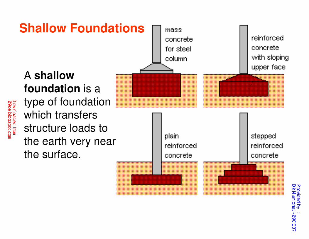
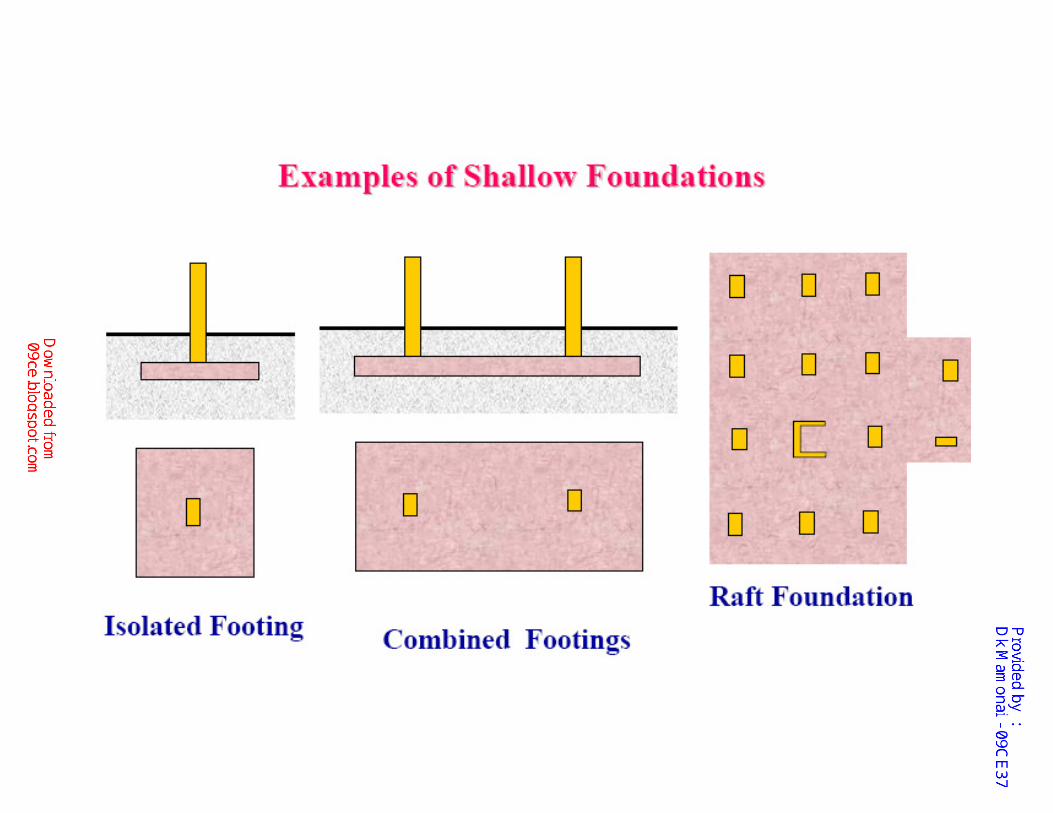
A shallow foundation is a
type of foundation
which transfers
structure loads to
the earth very near
the surface.
Shallow Foundations
Deep FoundationA deep foundation is a type of foundation which
transfers structure loads to a subsurface layer at a
certain depth.
Deep foundations can be used to transfer the loading to a deeper, more competent strata at depth if unsuitable soils are present near the surface.
This is usually at depths >3 m below the finished
ground level.
Deep foundation includes piles, piers and
caissons and also deep pad or strip foundations.
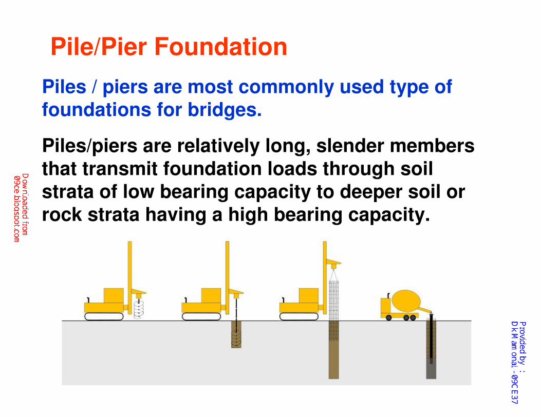
Pile/Pier Foundation
Piles/piers are relatively long, slender members
that transmit foundation loads through soil strata of low bearing capacity to deeper soil or rock strata having a high bearing capacity.
Piles / piers are most commonly used type of foundations for bridges.
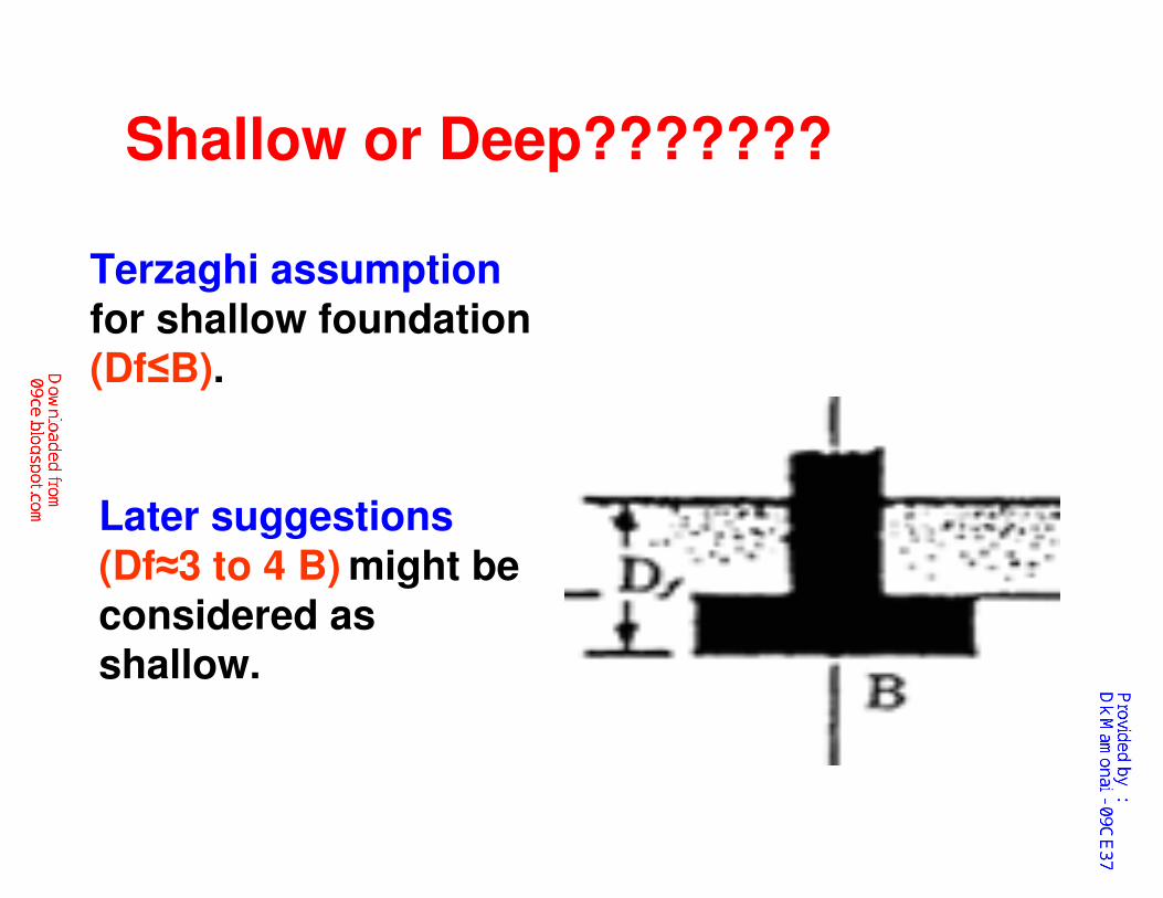
Terzaghi assumption
for shallow foundation (Df≤B).
Later suggestions
(Df≈3 to 4 B) might be considered as shallow.
Shallow or Deep???????
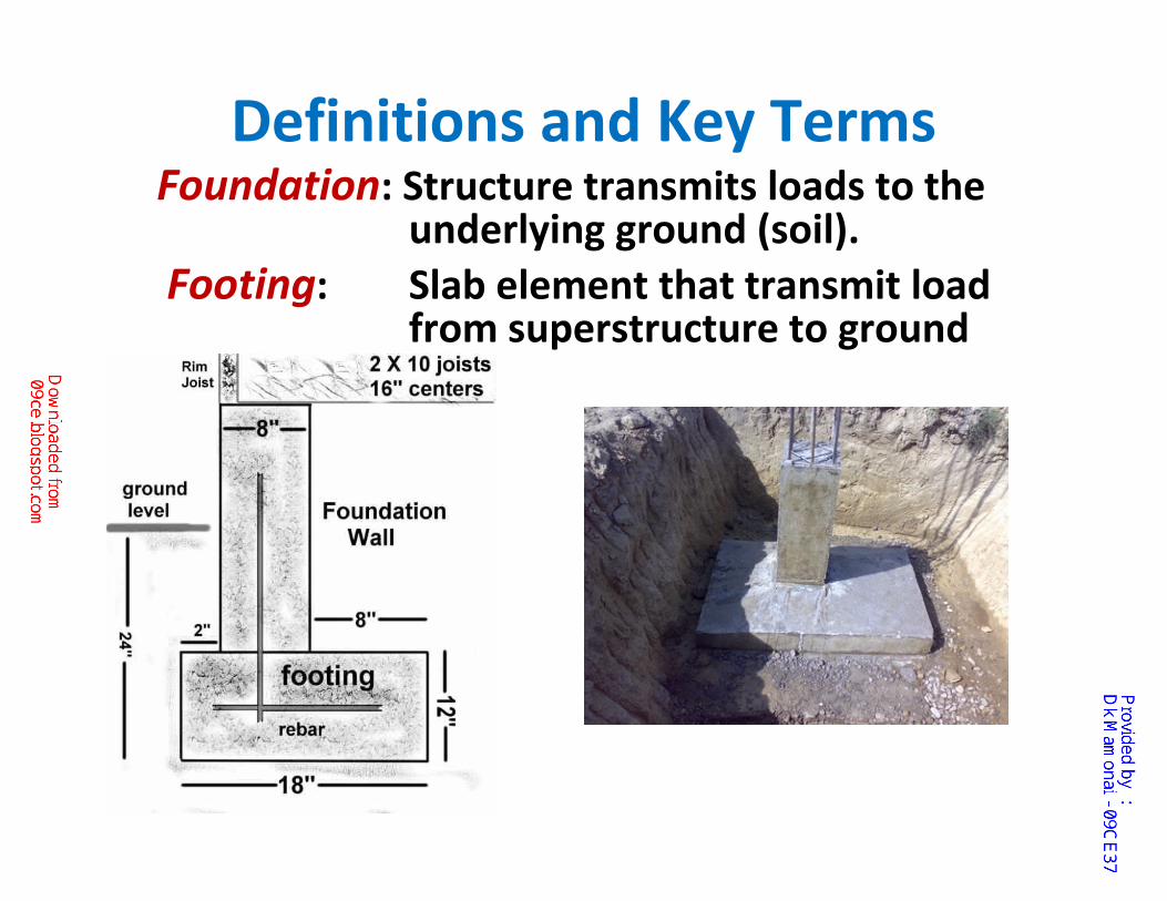
Definitions and Key TermsFoundation: Structure transmits loads to the
underlying ground (soil).
Footing: Slab element that transmit load from superstructure to ground
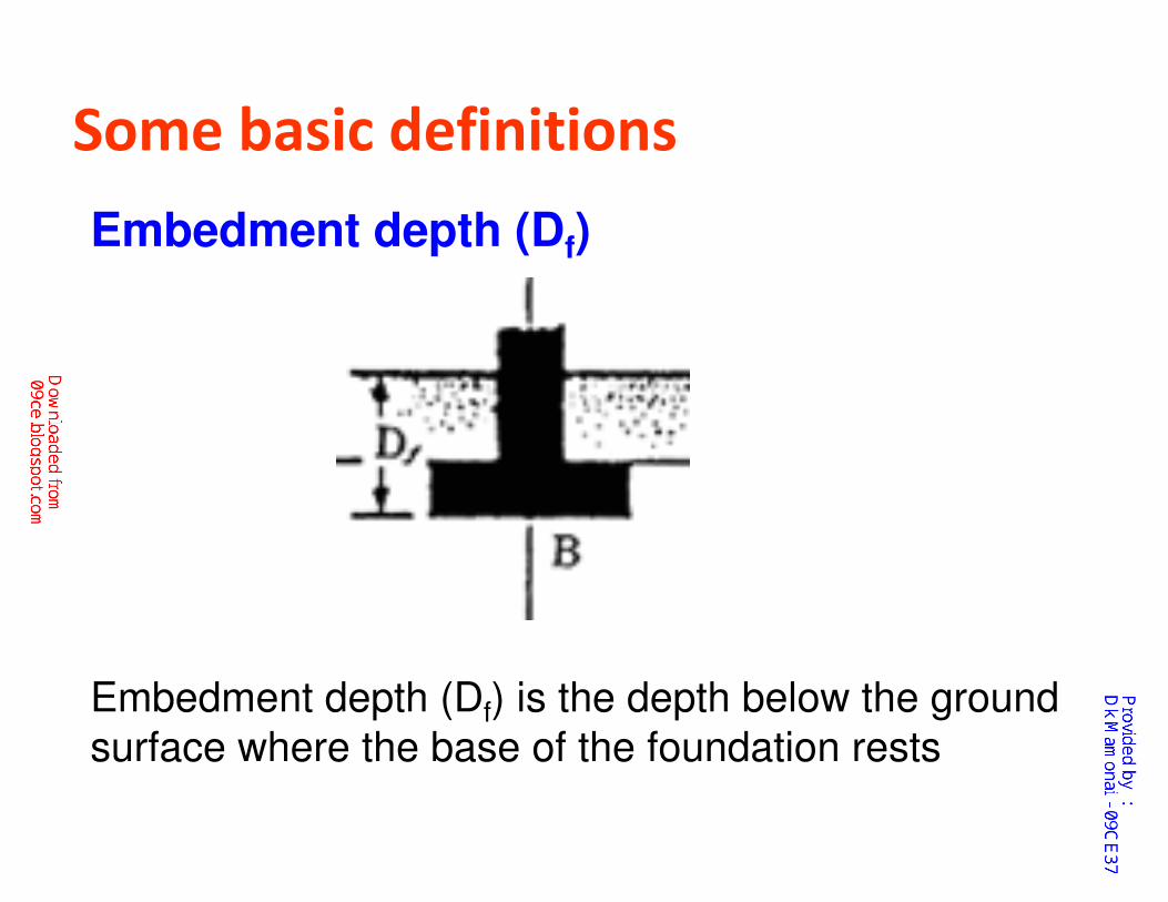
Some basic definitions
Embedment depth (Df)
Embedment depth (Df) is the depth below the ground
surface where the base of the foundation rests
Ultimate bearing capacity (qu) Ultimate bearing capacity is the maximum pressure that the soil can support (qu)
It is the pressure at which soil fails in shear
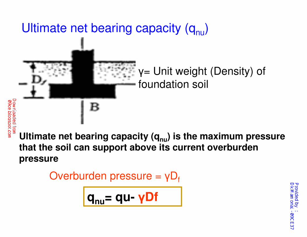
Ultimate net bearing capacity (qnu)
Ultimate net bearing capacity (qnu) is the maximum pressure that the soil can support above its current overburden pressure
γ= Unit weight (Density) of
foundation soil
Overburden pressure = γDf
qnu= qu- γDf
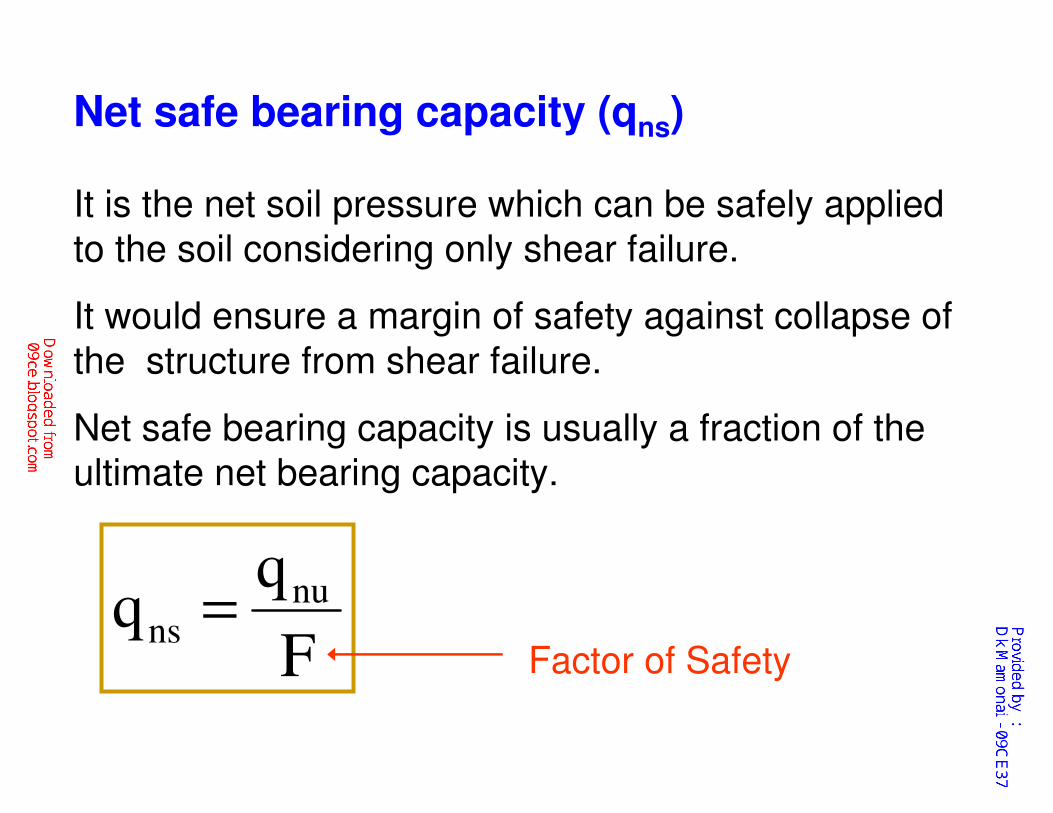
Net safe bearing capacity (qns)
It is the net soil pressure which can be safely applied
to the soil considering only shear failure.
It would ensure a margin of safety against collapse of
the structure from shear failure.
Net safe bearing capacity is usually a fraction of the
ultimate net bearing capacity.
F
qq nu
ns =Factor of Safety
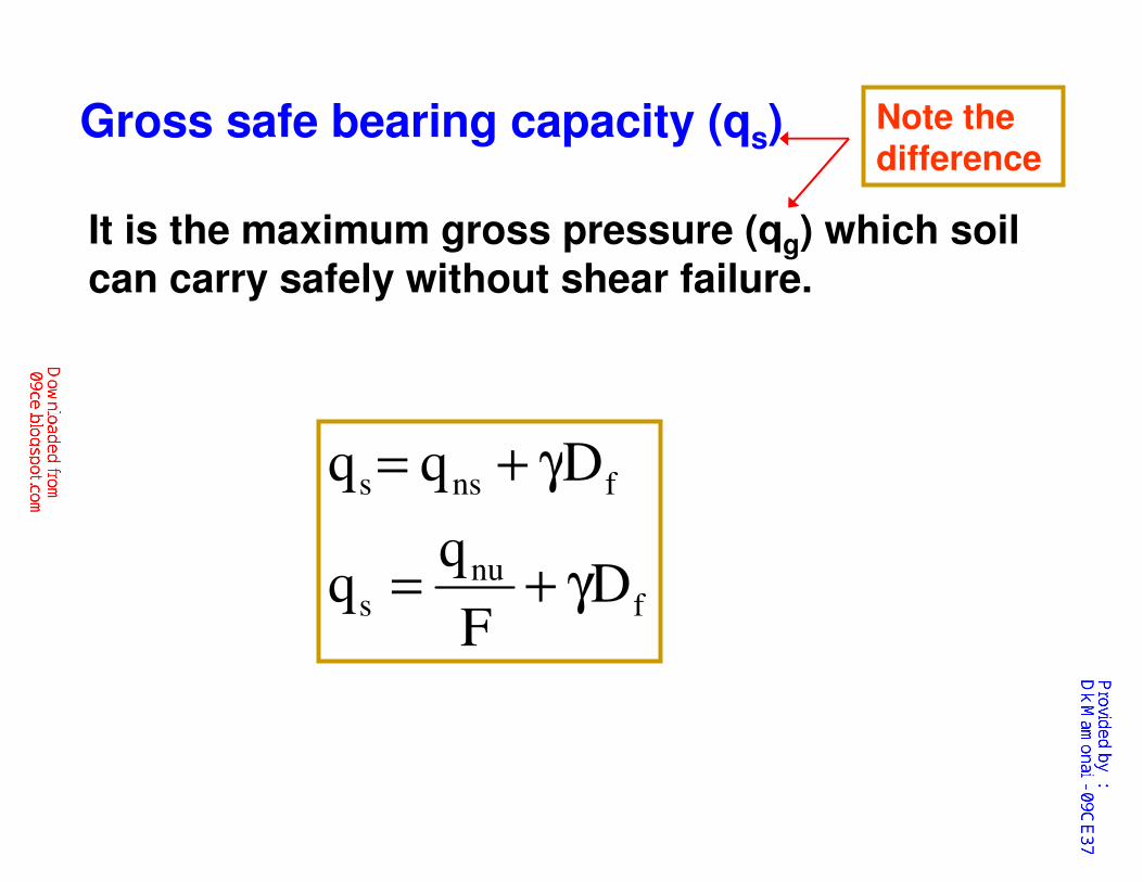
Gross safe bearing capacity (qs)
It is the maximum gross pressure (qg) which soil
can carry safely without shear failure.
fnu
s
fnss
DF
Dqq
γ+=
γ+=
Note the difference
Net safe settlement pressure (qnp)
It is the net pressure which the soil can carry without exceeding the allowable settlement
The maximum allowable settlement generally varies between 25 mm and 40 mm for individual footings
Net allowable bearing pressure (qna)
The net allowable bearing pressure is the net
bearing pressure which can be used for the design of foundations
The net allowable bearing pressure is also known
as
�Allowable soil pressure
�Allowable bearing pressure
�Allowable bearing capacity
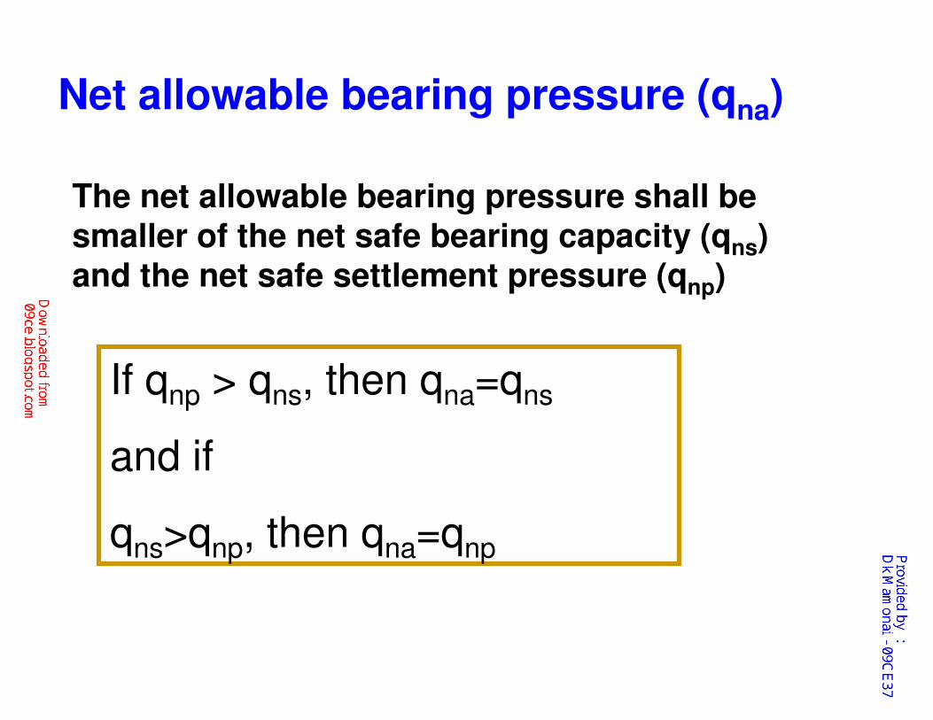
The net allowable bearing pressure shall be smaller of the net safe bearing capacity (qns) and the net safe settlement pressure (qnp)
Net allowable bearing pressure (qna)
If qnp > qns, then qna=qns
and if
qns>qnp, then qna=qnp
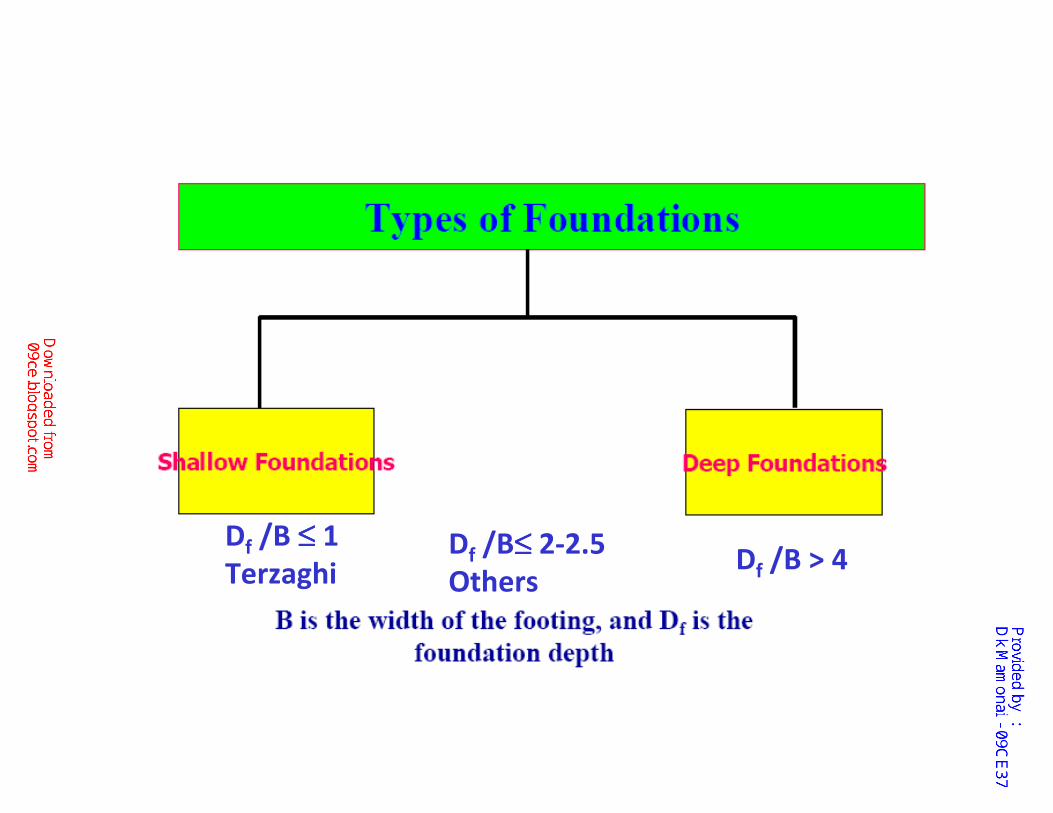
DDf /B ≤≤≤≤ 1
Terzaghi Df /B > 4Df /B≤≤≤≤ 2-2.5
Others
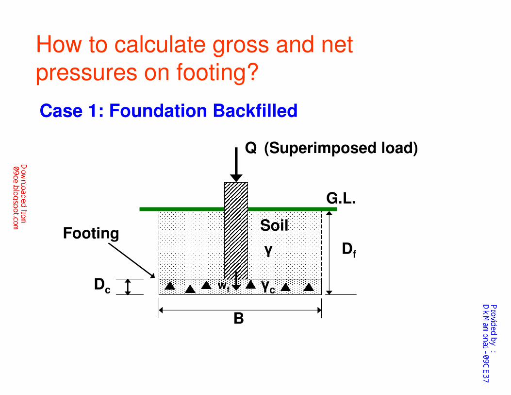
Q
G.L.
Soil
γ Df
γcwf
B
Footing
How to calculate gross and net
pressures on footing?
Case 1: Foundation Backfilled
(Superimposed load)
Dc
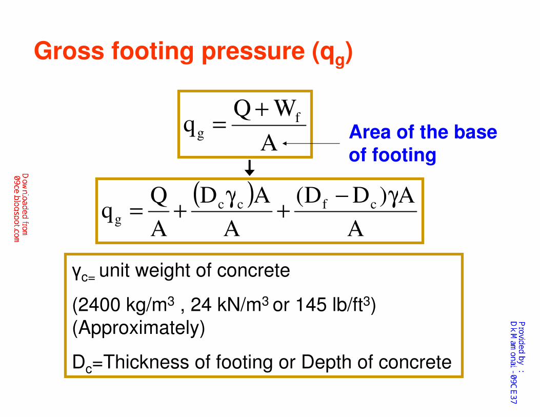
A
WQq f
g
+= Area of the base
of footing
( )A
A)DD(
A
AD
A
Qq cfcc
g
γ−+
γ+=
γc= unit weight of concrete
(2400 kg/m3 , 24 kN/m3 or 145 lb/ft3)
(Approximately)
Dc=Thickness of footing or Depth of concrete
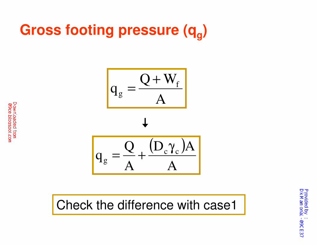
Gross footing pressure (qg)
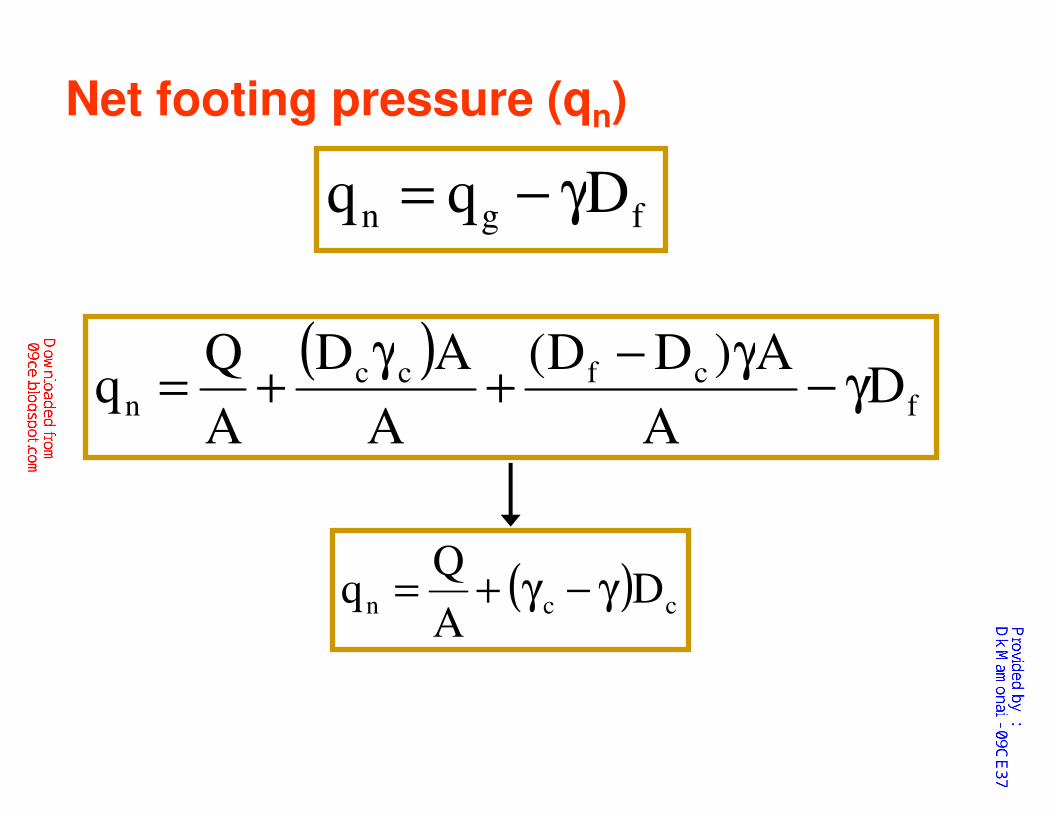
( ) ccn DA
Qq γ−γ+=
( )f
cfccn D
A
A)DD(
A
AD
A
Qq γ−
γ−+
γ+=
Net footing pressure (qn)
fgn Dqq γ−=

For simplicity
The difference between the unit weight of concrete
and unit weight of soil may be neglected
Unit weight of concrete = 24 kN/m3
Unit weight of soil = 20 kN/m3
A
Qqn =
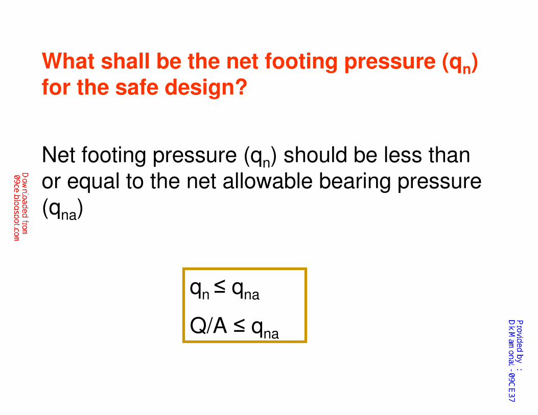
What shall be the net footing pressure (qn) for the safe design?
Net footing pressure (qn) should be less than or equal to the net allowable bearing pressure (qna)
qn ≤ qna
Q/A ≤ qna
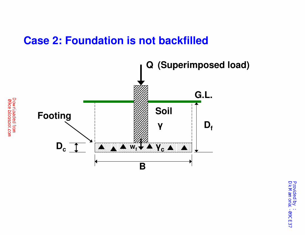
Q
G.L.
Soil
γ Df
γcwf
B
Footing
Case 2: Foundation is not backfilled
(Superimposed load)
Dc
A
WQq f
g
+=
( )A
AD
A
Qq cc
g
γ+=
Gross footing pressure (qg)
Check the difference with case1

fccn DDA
Qq γ−γ+=
( )f
ccn D
A
AD
A
Qq γ−
γ+=
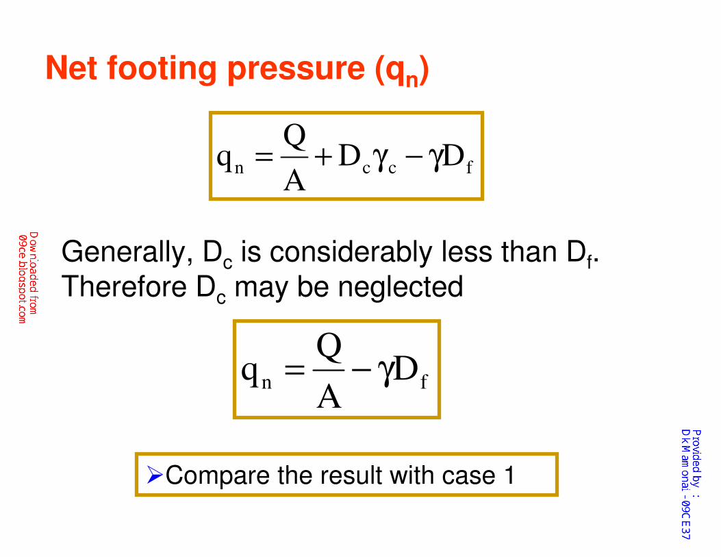
Net footing pressure (qn)
fgn Dqq γ−=
fccn DDA
Qq γ−γ+=
fn DA
Qq γ−=
Net footing pressure (qn)
Generally, Dc is considerably less than Df. Therefore Dc may be neglected
�Compare the result with case 1
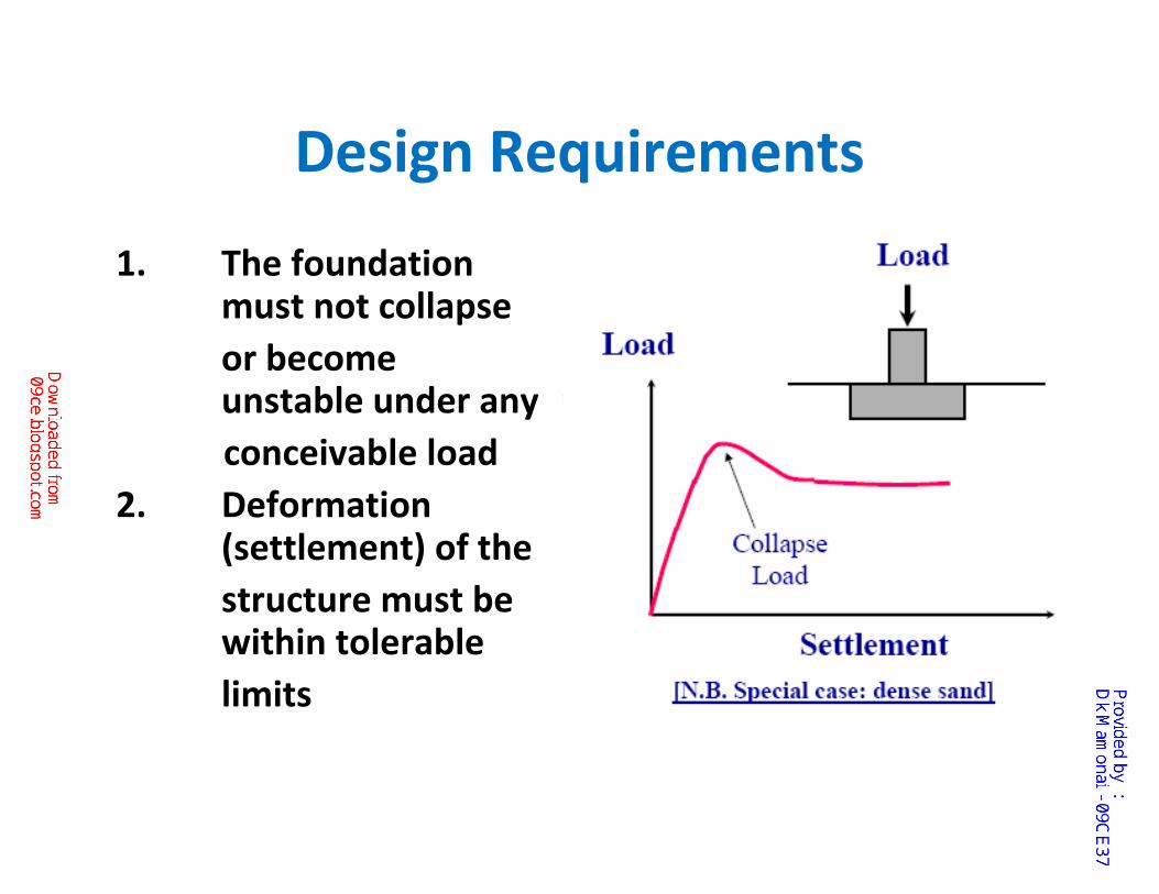
Design Requirements
1. The foundation must not collapse
or become unstable under any
conceivable load
2. Deformation (settlement) of the
structure must be within tolerable
limits
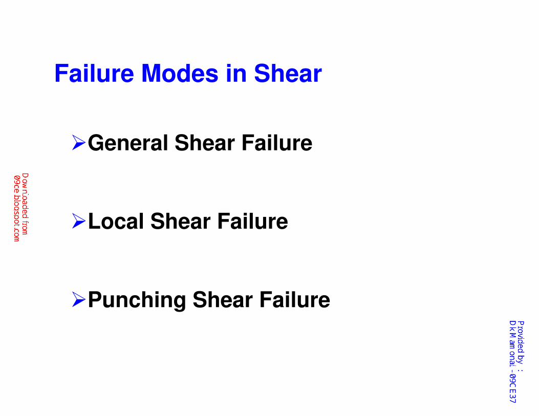
Failure Modes in Shear
�General Shear Failure
�Local Shear Failure
�Punching Shear Failure
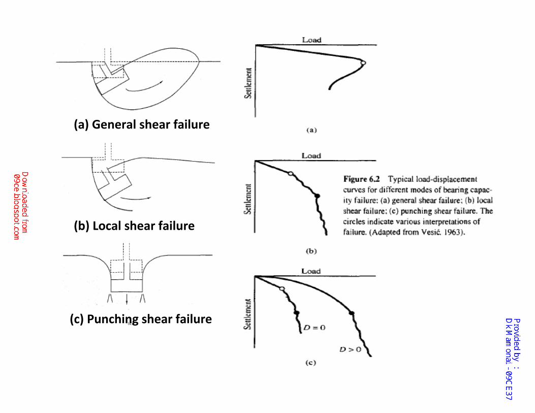
(c) Punching shear failure
(a) General shear failure
(b) Local shear failure
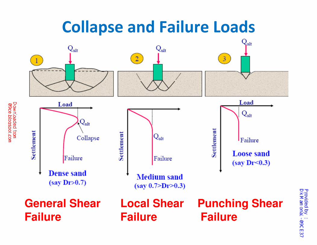
Collapse and Failure Loads
General Shear Local Shear Punching Shear
Failure Failure Failure
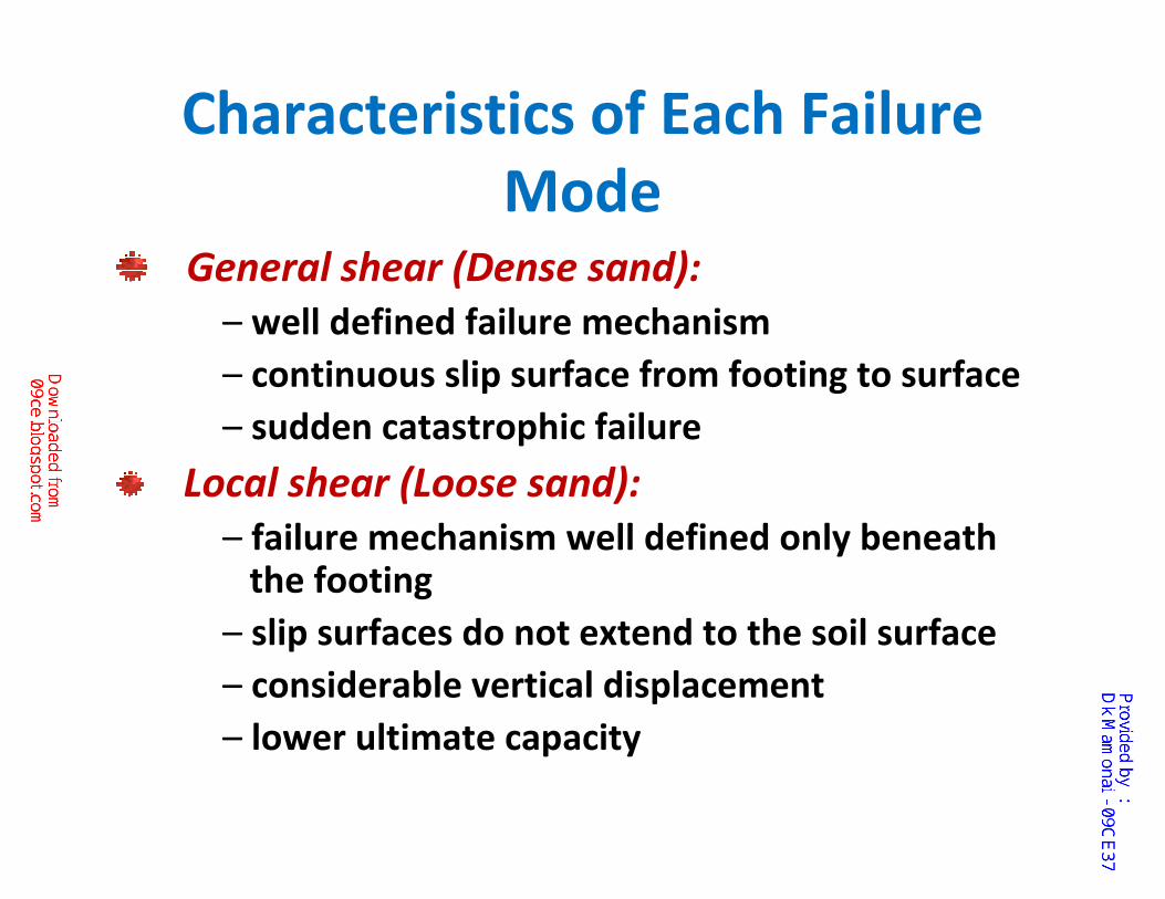
Characteristics of Each Failure
ModeGeneral shear (Dense sand):
– well defined failure mechanism
– continuous slip surface from footing to surface
– sudden catastrophic failure
Local shear (Loose sand):
– failure mechanism well defined only beneath the footing
– slip surfaces do not extend to the soil surface
– considerable vertical displacement
– lower ultimate capacity
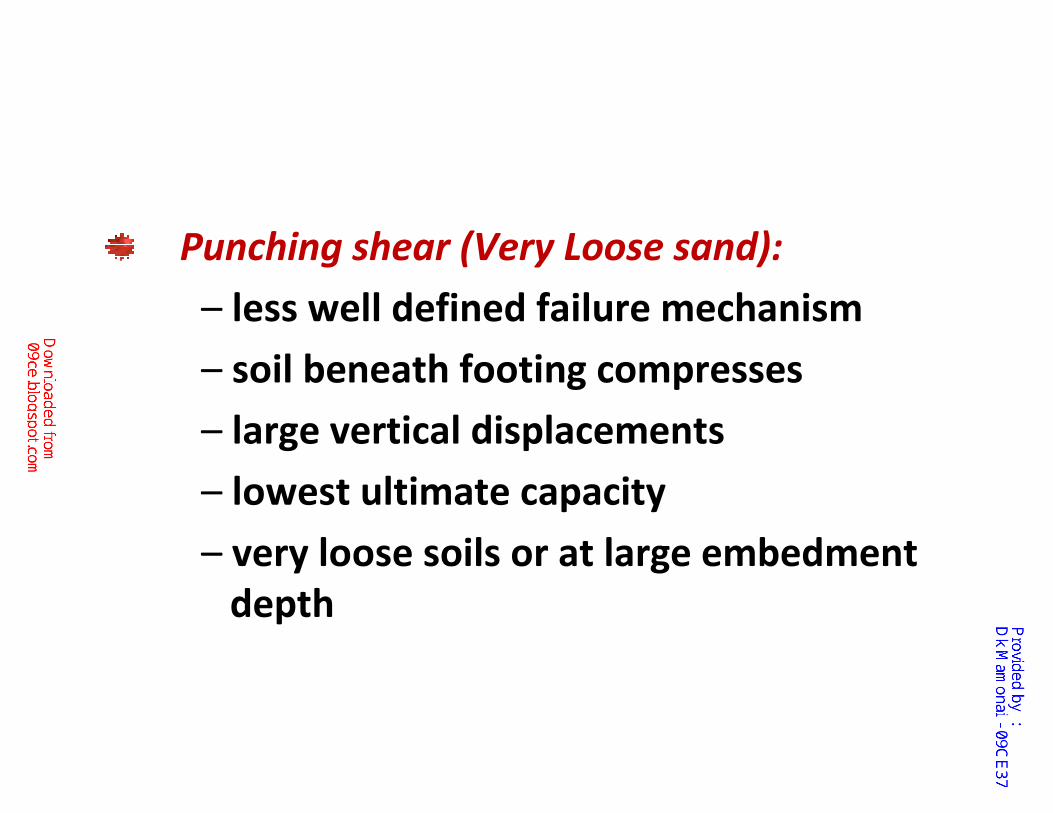
Punching shear (Very Loose sand):
– less well defined failure mechanism
– soil beneath footing compresses
– large vertical displacements
– lowest ultimate capacity
– very loose soils or at large embedment
depth
Guide lines to know whether
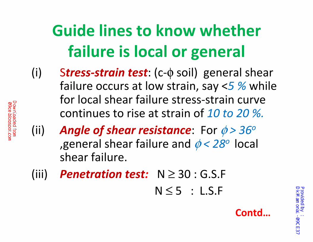
failure is local or general(i) Stress-strain test: (c-φ soil) general shear
failure occurs at low strain, say <5 % while for local shear failure stress-strain curve continues to rise at strain of 10 to 20 %.
(ii) Angle of shear resistance: For φ > 36o
,general shear failure and φ < 28o local shear failure.
(iii) Penetration test: N ≥ 30 : G.S.F
N ≤ 5 : L.S.F
Contd…
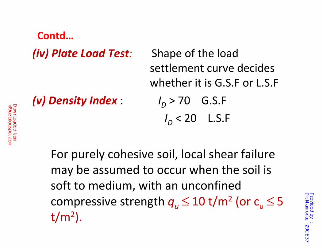
(iv) Plate Load Test: Shape of the load
settlement curve decides
whether it is G.S.F or L.S.F
(v) Density Index : ID > 70 G.S.F
ID < 20 L.S.F
For purely cohesive soil, local shear failure
may be assumed to occur when the soil is
soft to medium, with an unconfined
compressive strength qu ≤ 10 t/m2 (or cu ≤ 5
t/m2).
Contd…
� Shallow foundations in rock and undrained
clays are governed by the general shear
case.
� Shallow foundations in dense sands are
governed by the general shear case. In this
context, a dense sand is one with a relative
density, Dr , greater than about 67%.
General considerations for type of failure in Shallow Foundations
� Shallow foundations on loose to medium
dense sands (30% < Dr< 67%) are probably
governed by local shear.
� Shallow foundations on very loose sand
(Dr < 30%) are probably governed by
punching shear.
General Considerations for type of failure Shallow Foundations
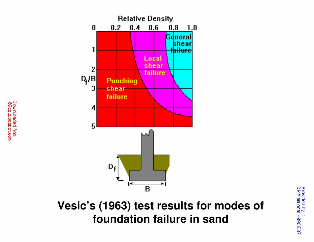
Vesic’s (1963) test results for modes of
foundation failure in sand
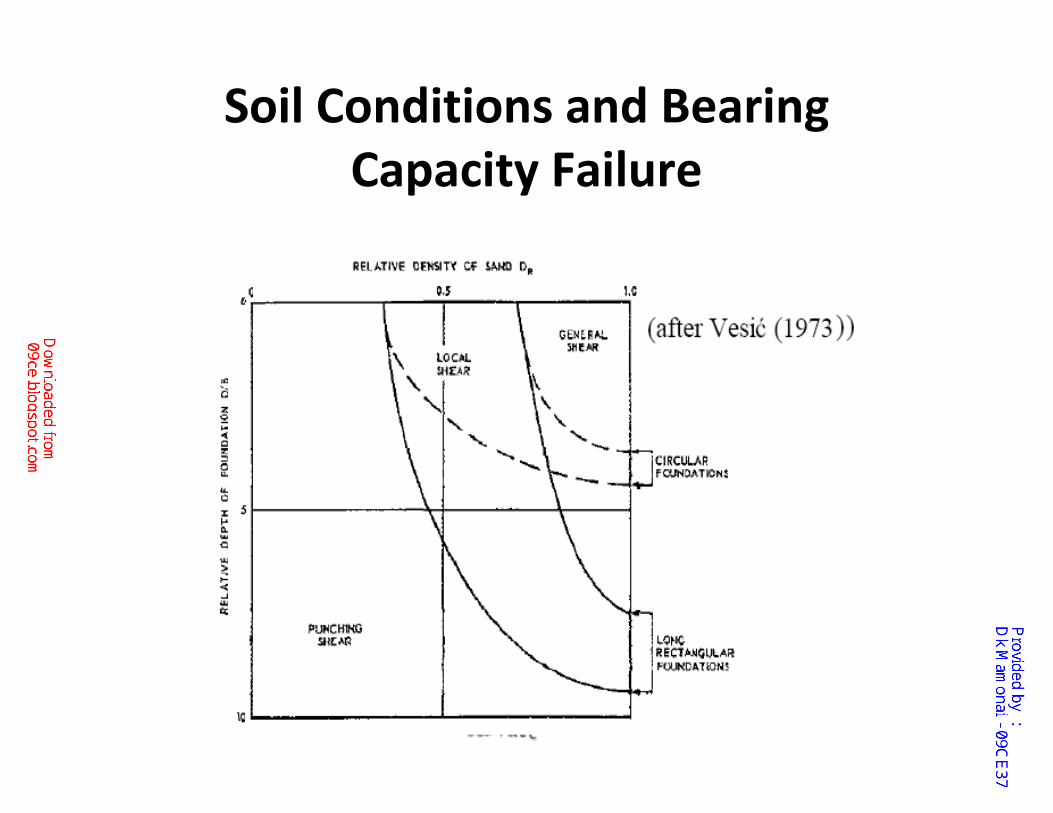
Soil Conditions and Bearing
Capacity Failure
Foundation Requirements
1. Safe against failure (bearing capacity or
structural failure)
2. Should not exceed tolerable settlement
(probable maximum and differential settlement)
3. Its construction should not make any change to
existing structure.
4. Should be adequate depth from consideration
of adverse environment influence:
i. Zones of high volume change due to
moisture fluctuations.
ii. Depth of frost penetration
iii. Organic matter; peat and muck.
iv. Abandoned garbage dumps or loosed fill
areas.
v. Scouring depth
Development of Bearing Capacity
Theory
BEARING CAPACITY ANALYSES IN
SOIL-GENERAL SHEAR CASE
To analyze spread footings for bearing capacity
failures and design them in a way to avoid such
failures, we must understand the relationship
among
bearing capacity,
load,
footing dimensions,
and soil properties.
� Assessments of the performance of real
foundations, including full-scale load tests.
� Load tests on model footings.
� Limit equilibrium analyses.
� Detailed stress analyses, such as finite
element method (FEM) analyses.
Various researchers have studied these relationships using a variety of techniques, including:
• Full-scale load tests
�consist of constructing real spread footings
and loading them to failure,
�most precise way to evaluate bearing capacity.
�such tests are very expensive,
�and thus are rarely, if ever, performed as a
part of routine design.
�A few such tests have been performed for
research purposes.
Model footing tests
�have been used quite extensively,
�the cost of these tests is far below that for full-scale tests.
�Unfortunately, model tests have their limitations, because of uncertainties in applying the proper scaling factors.
�However, the advent of centrifuge model (Physical Modeling) tests has partially overcome this problem.
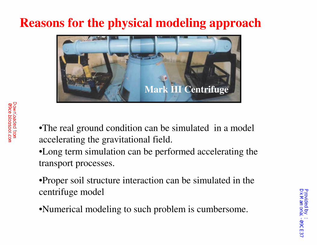
Mark III Centrifuge
•Long term simulation can be performed accelerating the
transport processes.
•Proper soil structure interaction can be simulated in the
centrifuge model
•Numerical modeling to such problem is cumbersome.
•The real ground condition can be simulated in a model
accelerating the gravitational field.
Reasons for the physical modeling approach
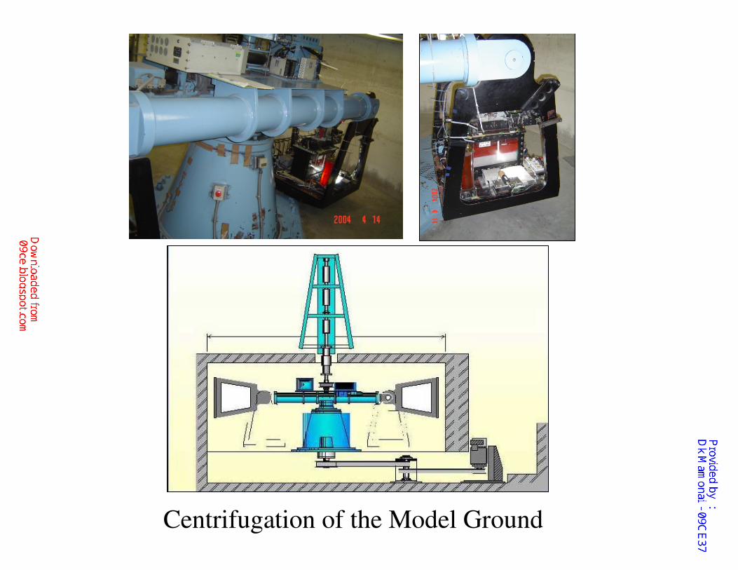
Centrifugation of the Model Ground
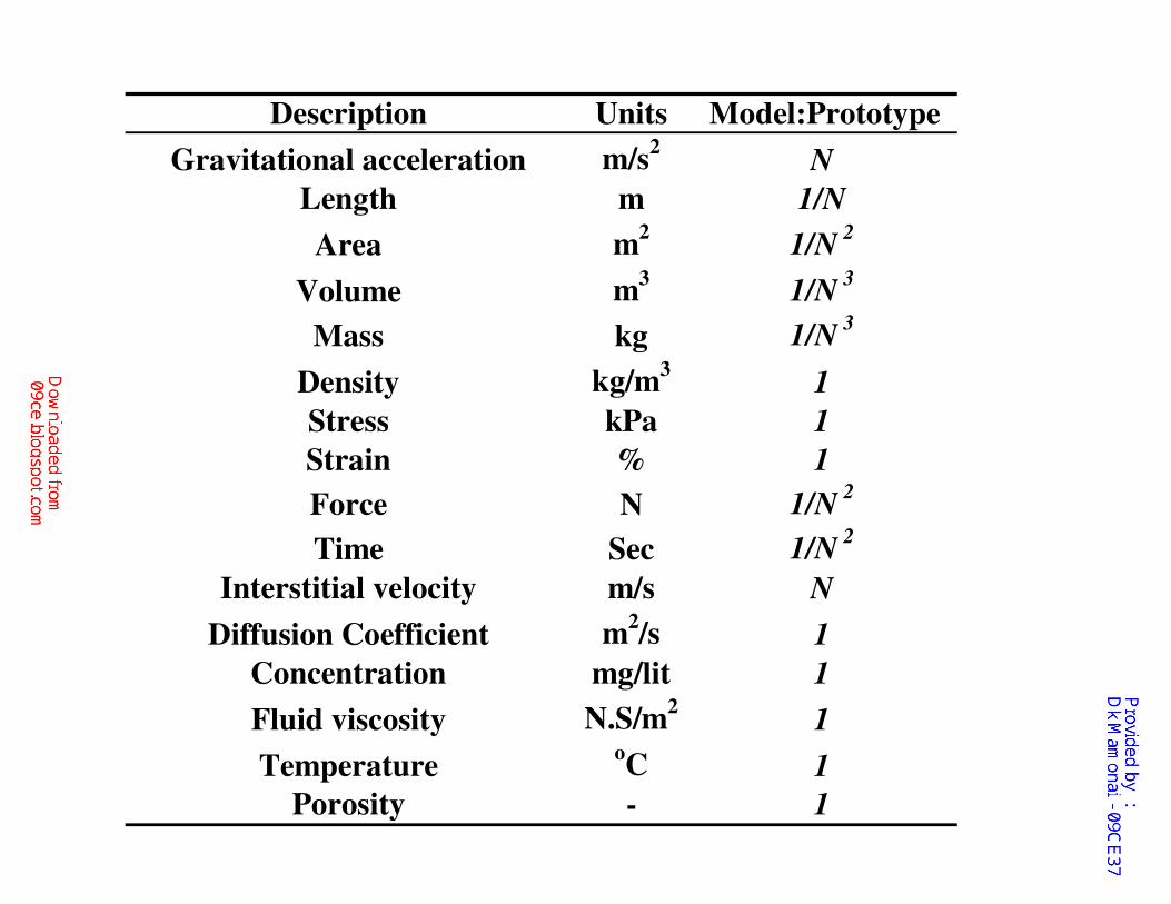
Description Units Model:Prototype
Gravitational acceleration m/s2
N
Length m 1/N
Area m2
1/N2
Volume m3
1/N3
Mass kg 1/N3
Density kg/m3
1
Stress kPa 1
Strain % 1
Force N 1/N2
Time Sec 1/N2
Interstitial velocity m/s N
Diffusion Coefficient m2/s 1
Concentration mg/lit 1
Fluid viscosity N.S/m2
1
TemperatureoC 1
Porosity - 1
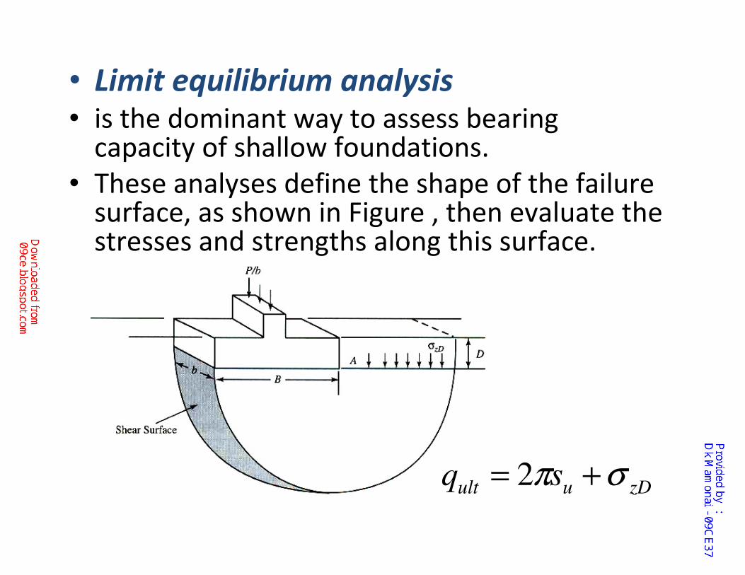
• Limit equilibrium analysis • is the dominant way to assess bearing
capacity of shallow foundations.
• These analyses define the shape of the failure surface, as shown in Figure , then evaluate the stresses and strengths along this surface.
zDuult sq σπ += 2
• Limit equilibrium analysis
• These methods of analysis have their roots in Prandtl' s studies of the punching resistance of metals (Prandtl, 1920).
• He considered the ability of very thick masses of metal (i.e., not sheet metal) to resist concentrated loads.
• Limit equilibrium analyses usually include empirical factors developed from model tests.

The limit equilibrium method for Bearing capacity of Soil
The objective of this derivation is to obtain a formula for the ultimate bearing capacity, qult ,which is the bearing pressure
required to cause a bearing capacity failure.
Consider the continuous footing
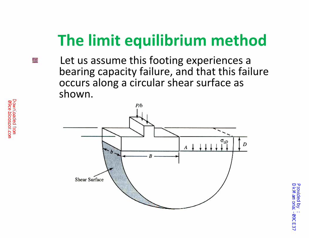
The limit equilibrium method Let us assume this footing experiences a bearing capacity failure, and that this failure occurs along a circular shear surface as shown.
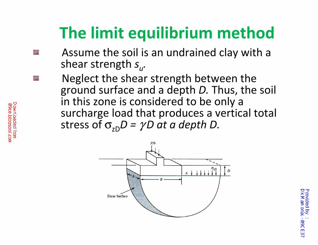
The limit equilibrium method Assume the soil is an undrained clay with a shear strength su.
Neglect the shear strength between the ground surface and a depth D. Thus, the soil in this zone is considered to be only a surcharge load that produces a vertical total stress of σzDD = γ D at a depth D.
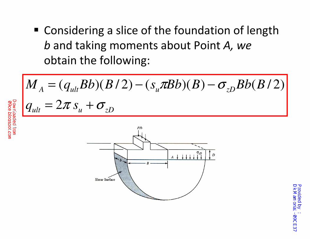
� Considering a slice of the foundation of length
b and taking moments about Point A, we
obtain the following:
zDuult
zDuultA
sq
BBbBBbsBBbqM
σπ
σπ
+=
−−=
2
)2/())(()2/)((
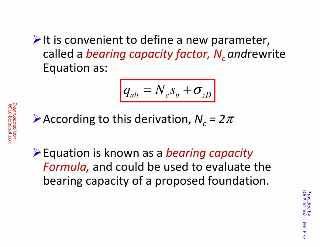
�It is convenient to define a new parameter, called a bearing capacity factor, Nc andrewriteEquation as:
�According to this derivation, Nc = 2π
�Equation is known as a bearing capacity Formula, and could be used to evaluate the bearing capacity of a proposed foundation.
zDucult sNq σ+=
This simplified formula has only limited applicability in practice because it considers
�only continuous footings and undrained soil conditions (φ = 0), and
�it assumes the foundation rotates as the bearing capacity failure occurs.
However, this simple derivation illustrates the general methodology required to develop more comprehensive bearing capacity formulas.
Analytical Solution/Approach
No exact analytical solution for computing
bearing capacity of footings is available at
present because……
the basic system of equations describing
the yield problems is nonlinear.

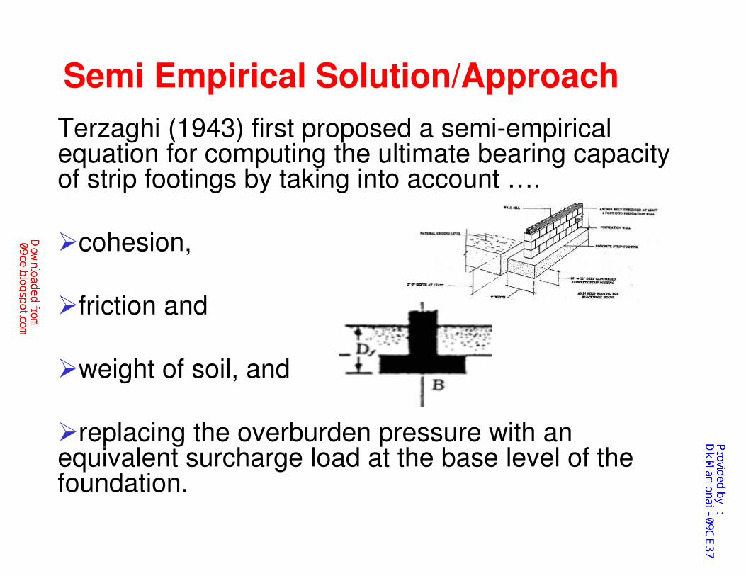
Semi Empirical Solution/Approach
Terzaghi (1943) first proposed a semi-empirical equation for computing the ultimate bearing capacity of strip footings by taking into account ….
�cohesion,
�friction and
�weight of soil, and
�replacing the overburden pressure with an equivalent surcharge load at the base level of the foundation.
Further Developments
• Skempton (1951)
• Meyerhof (1953)
• Brinch Hanson (1961)
• De Beer and Ladanyi (1961)
• Meyerhof (1963)
• Brinch Hanson (1970)
• Vesic′ (1973, 1975)
Semi Empirical Solution/Approach

�Occasionally, geotechnical engineers perform
more detailed bearing capacity analyses using
numerical methods, such as the finite element
method (FEM).
�These analyses are more complex, and are
justified only on very critical and unusual
projects.
Numerical Solution/Approach
�The ultimate bearing capacity, or the
allowable soil pressure, can be calculated
either from bearing capacity theories or from
some of the in situ tests like Plate load test.
�Each theory has its own good and bad points.
We will consider only
�limit equilibrium methods of bearing capacity
analyses, and…
�In-situ tests
because these methods are used on the
overwhelming majority of projects.
Our Approach
Development of Bearing Capacity
Theory�Application of limit equilibrium methods first
done by Prandtl on the punching of thick masses of metal.
�Prandtl's methods adapted by Terzaghi to bearing capacity failure of shallow foundations.
�Vesicʼ and others improved on Terzaghi's original
theory and added other factors for a more complete analysis
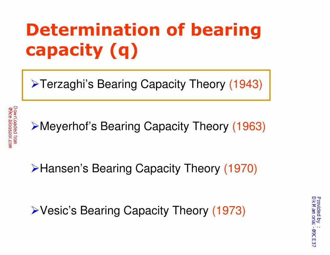
Determination of bearing capacity (q)
�Terzaghi’s Bearing Capacity Theory (1943)
�Meyerhof’s Bearing Capacity Theory (1963)
�Hansen’s Bearing Capacity Theory (1970)
�Vesic’s Bearing Capacity Theory (1973)
Karl Terzaghi (1883-1963)
�Father of modern soil mechanics
�Born in Prague, Czechoslovakia
�Wrote “Erdbaumechanick” in 1925
�Taught at MIT (1925-1929)
�Taught at Harvard (1938 and after)
Karl Terzaghi at Harvard, 1940
Semi Empirical Solution/Approach
Terzaghi (1943) first proposed a semi-empirical equation for computing the ultimate bearing capacity of strip footings by taking into account ….
�cohesion,
�friction and
�weight of soil, and
�replacing the overburden pressure with an equivalent surcharge load at the base level of the foundation.
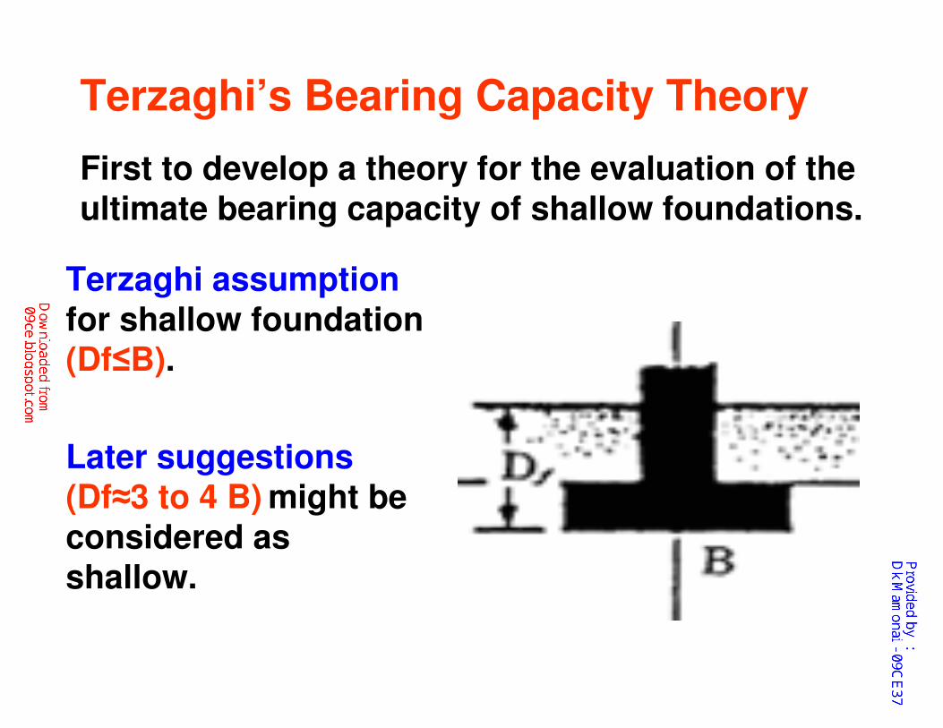
Terzaghi’s Bearing Capacity Theory
First to develop a theory for the evaluation of the
ultimate bearing capacity of shallow foundations.
Terzaghi assumption
for shallow foundation (Df≤B).
Later suggestions(Df≈3 to 4 B) might be
considered as shallow.
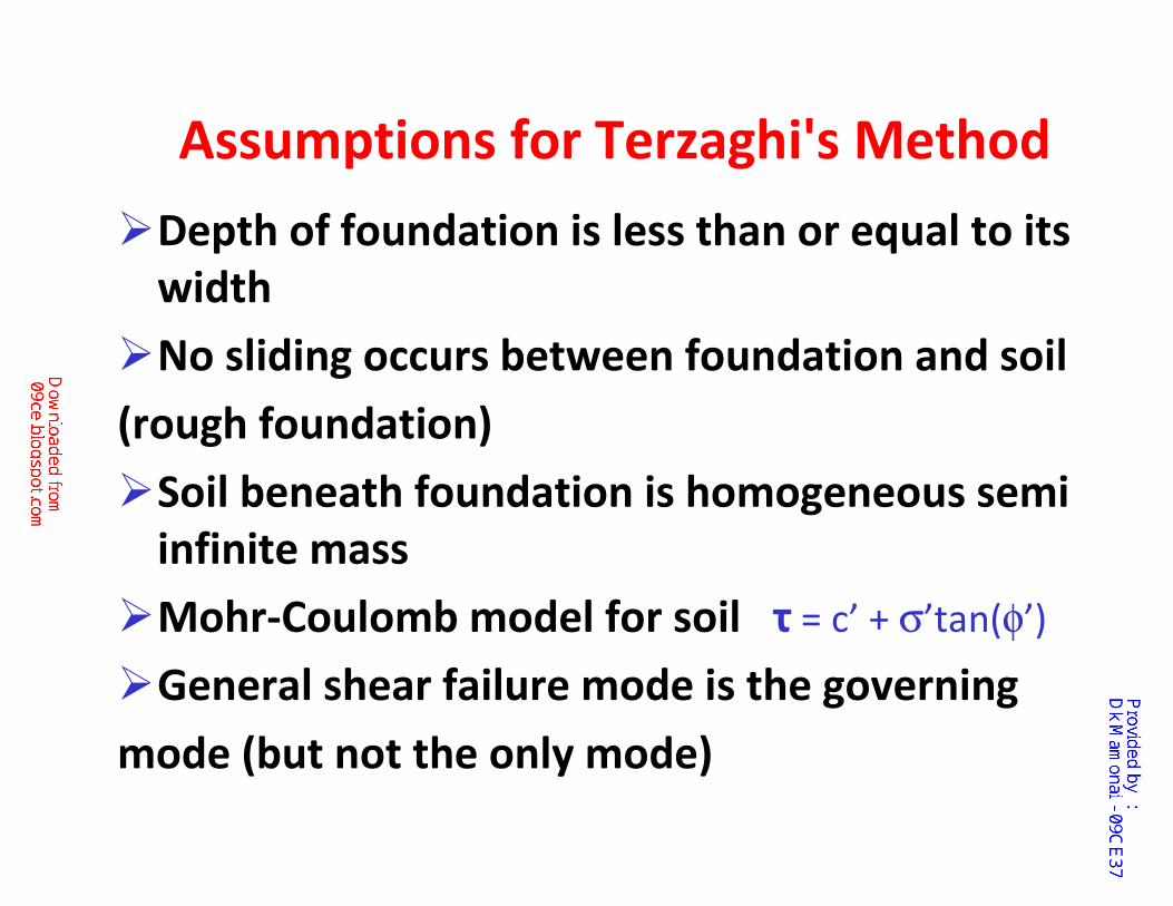
Assumptions for Terzaghi's Method
�Depth of foundation is less than or equal to its
width
�No sliding occurs between foundation and soil
(rough foundation)
�Soil beneath foundation is homogeneous semi
infinite mass
�Mohr-Coulomb model for soil τ = c’ + σ’tan(φ’)
�General shear failure mode is the governing
mode (but not the only mode)
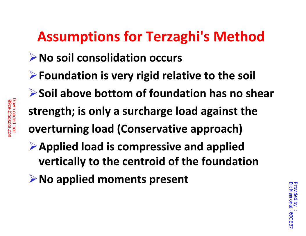
Assumptions for Terzaghi's Method
�No soil consolidation occurs
�Foundation is very rigid relative to the soil
�Soil above bottom of foundation has no shear
strength; is only a surcharge load against the
overturning load (Conservative approach)
�Applied load is compressive and applied
vertically to the centroid of the foundation
�No applied moments present
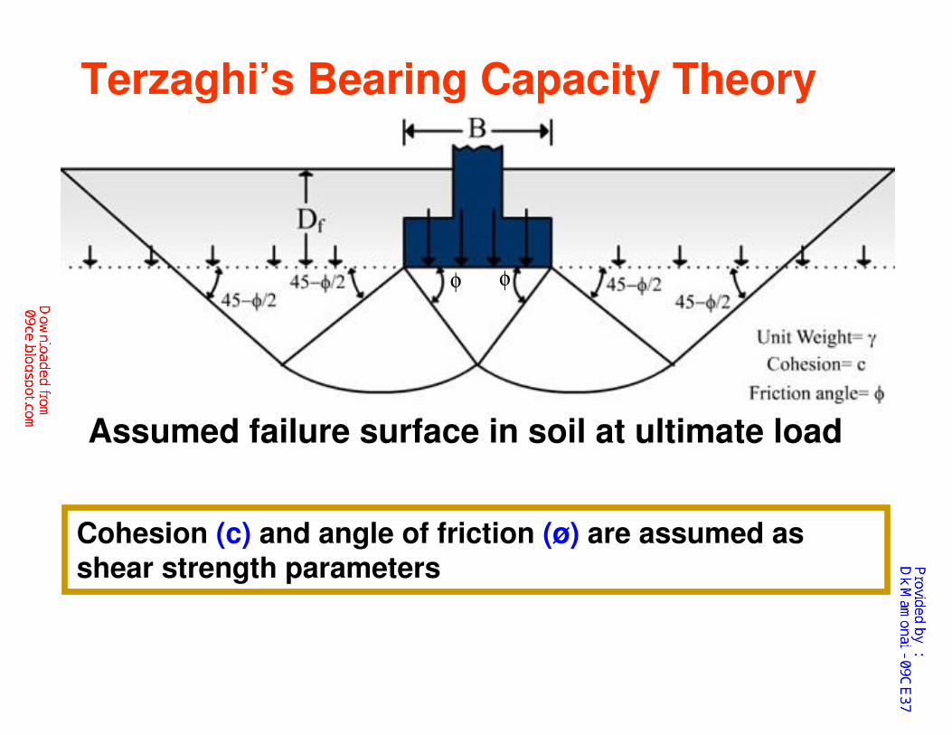
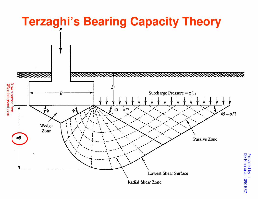
Terzaghi’s Bearing Capacity Theory
Assumed failure surface in soil at ultimate load
φ
Cohesion (c) and angle of friction (ø) are assumed as shear strength parameters
φ

Terzaghi’s Bearing Capacity Theory
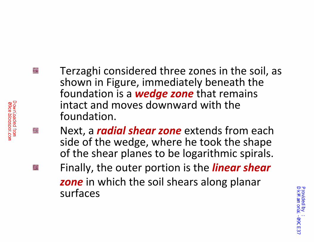
Terzaghi considered three zones in the soil, as shown in Figure, immediately beneath the foundation is a wedge zone that remains intact and moves downward with the foundation.
Next, a radial shear zone extends from each side of the wedge, where he took the shape of the shear planes to be logarithmic spirals.
Finally, the outer portion is the linear shear
zone in which the soil shears along planar surfaces
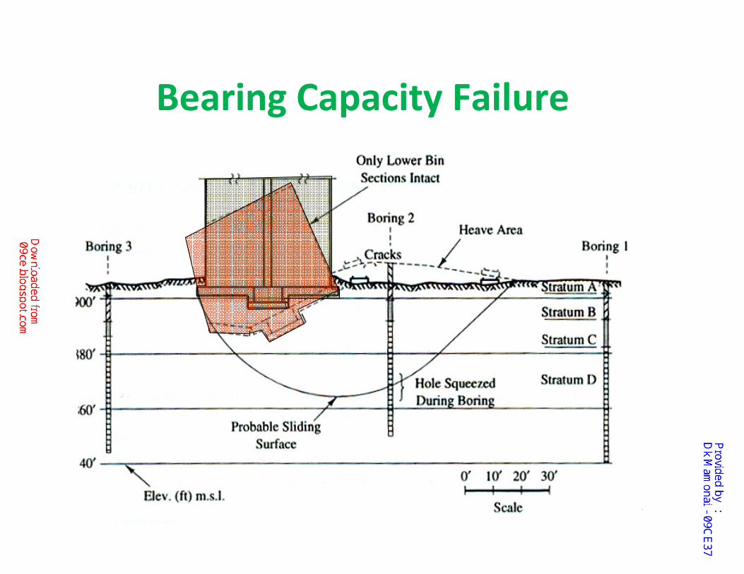
Bearing Capacity Failure
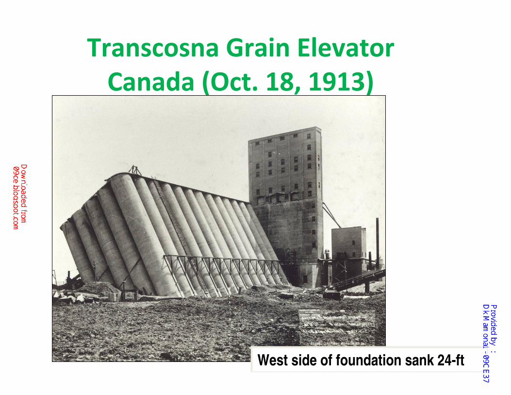
Transcosna Grain Elevator
Canada (Oct. 18, 1913)
West side of foundation sank 24-ft
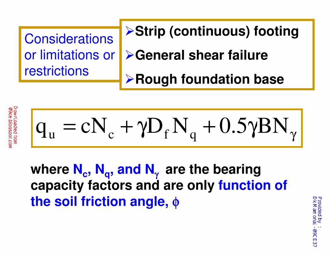
γγ+γ+= BN5.0NDcNq qfcu
where Nc, Nq, and Nγγγγ are the bearing capacity factors and are only function of
the soil friction angle, φφφφ
�Strip (continuous) footing
�General shear failure
�Rough foundation base
Considerations or limitations or restrictions

Terzaghi’s Bearing Capacity Theory
Assumed failure surface in soil at ultimate load
φ
Cohesion (c) and angle of friction (ø) are assumed as shear strength parameters
φ

γγ+γ+= BN5.0NDcNq qfcu
Refers to the vertical
stress of the soil
above the base of
the foundation
Refers to the vertical
stress of a soil mass
of thickness B,
below the base of
the footing
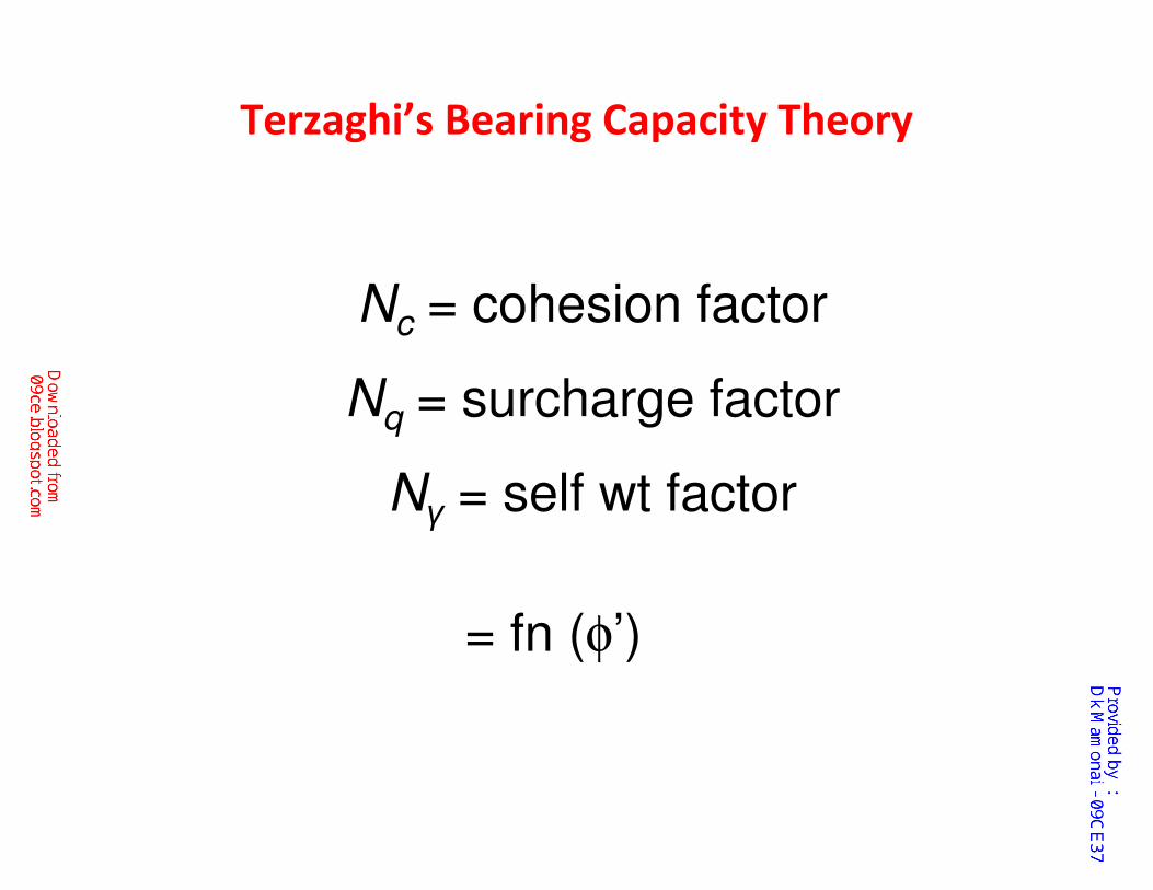
Nc = cohesion factor
Nq = surcharge factor
Nγ = self wt factor
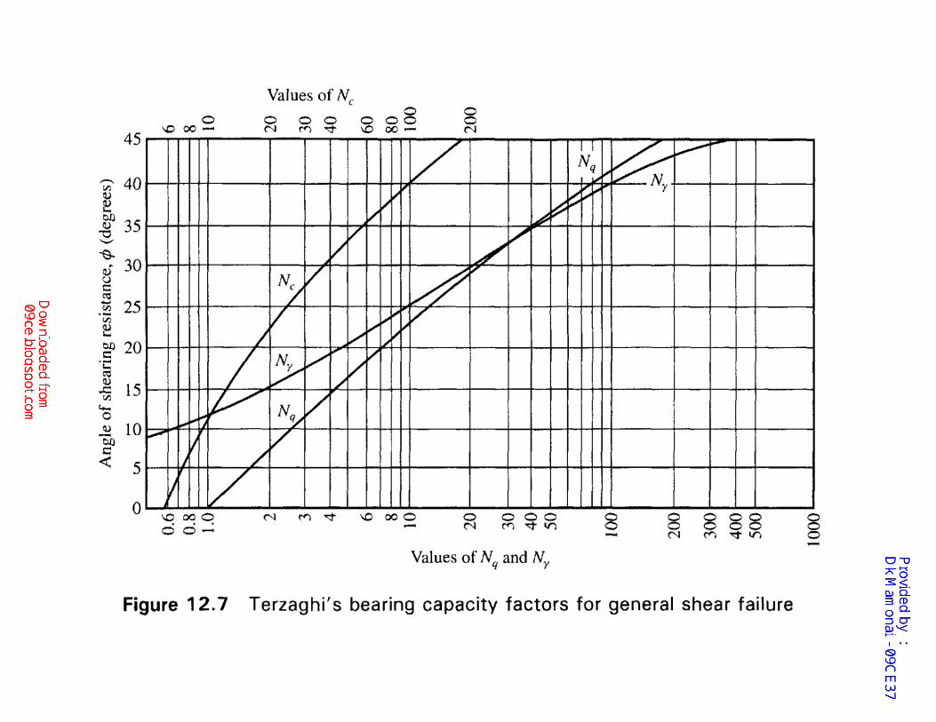
Terzaghi’s Bearing Capacity Theory
= fn (φ’)
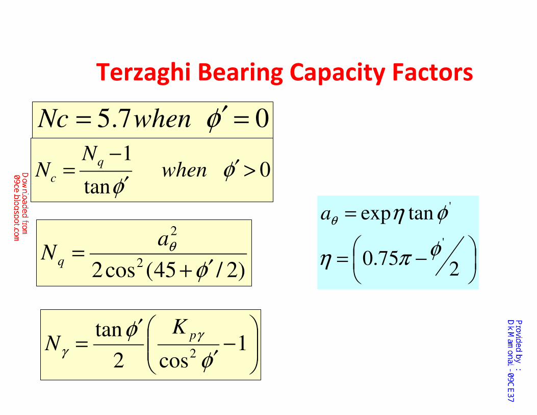
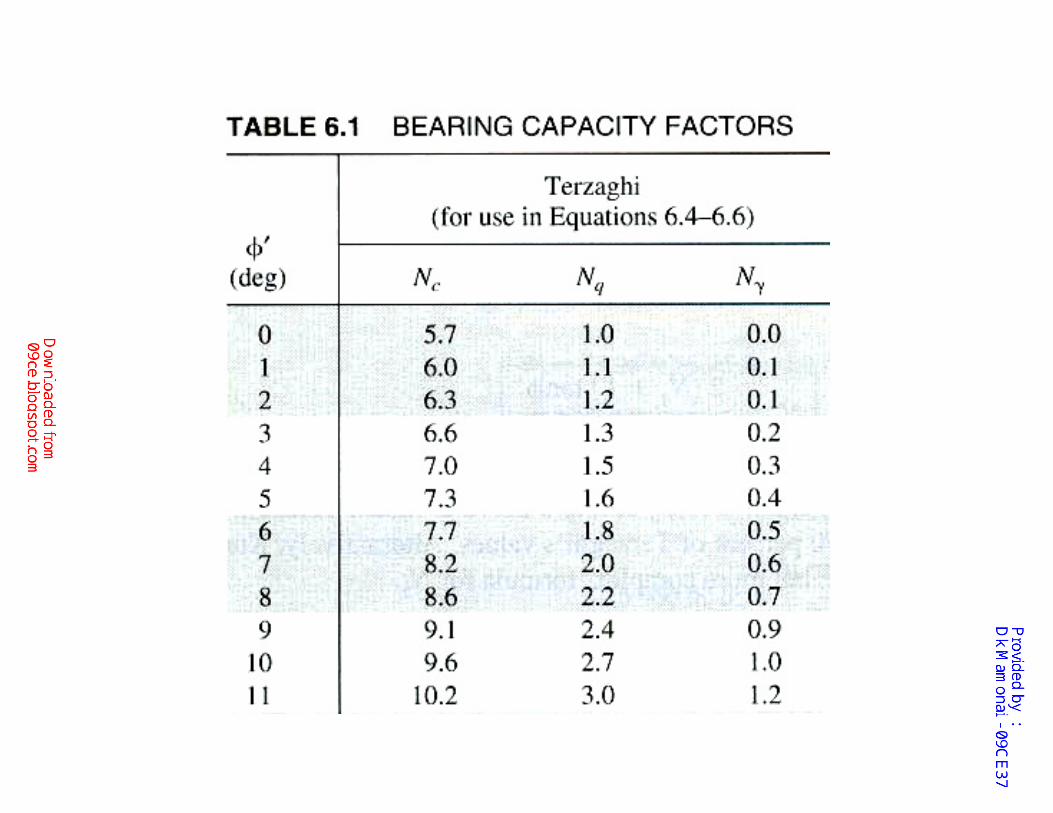
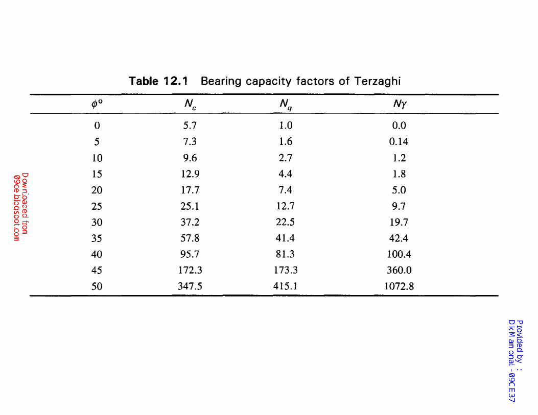
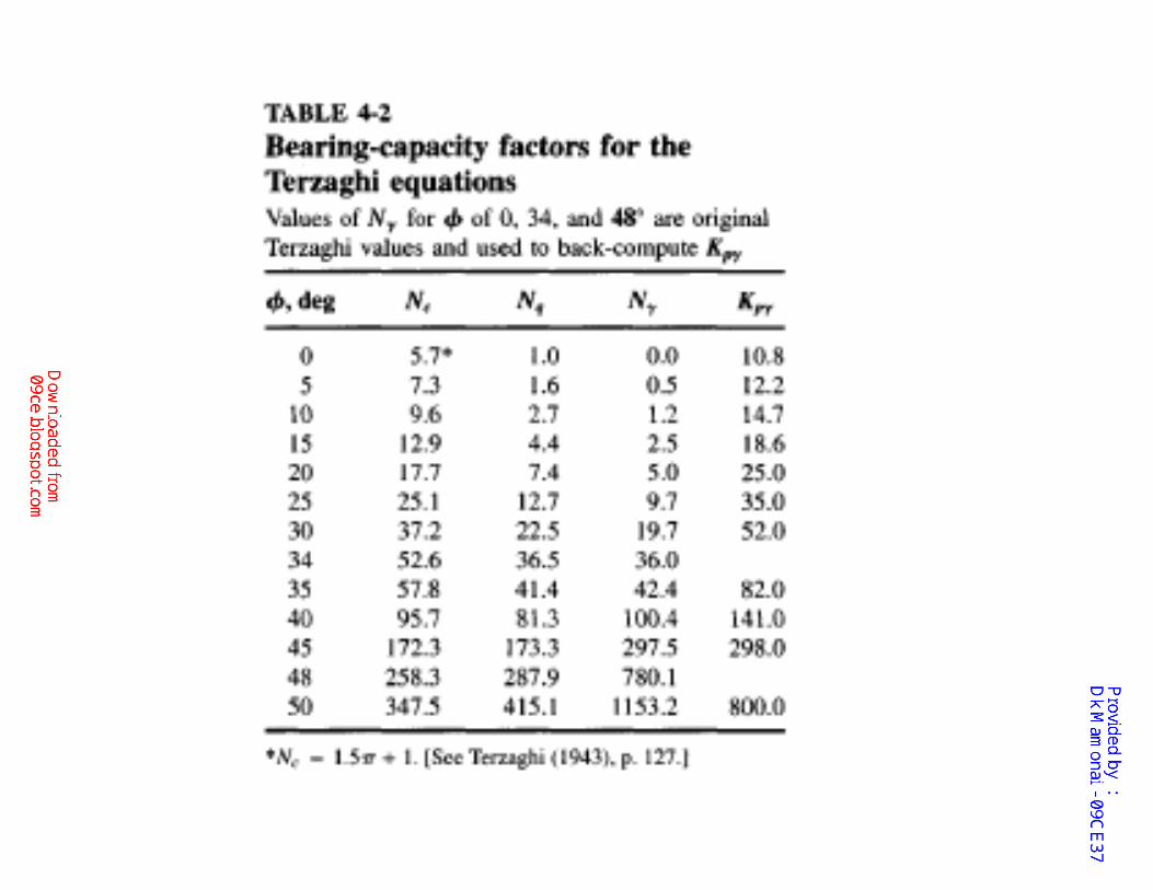
Terzaghi Bearing Capacity Factors
07.5 =′= φwhenNc
)2/45(cos2 2
2
φθ
′+=
aNq
−=
=
275.0
tanexp
'
'
φπη
φηθa
−
′
′= 1
cos2
tan2 φ
φ γ
γ
pKN
0tan
1>′
′
−= φ
φwhen
NN
q
c
Terzaghi developed his theory for
continuous foundations (i.e., those with a
very large L/B ratio).
This is the simplest case because it is a two-
dimensional problem.
He then extended it to square and round
foundations by adding empirical coefficients
obtained from model tests and produced the
following bearing capacity formulas:
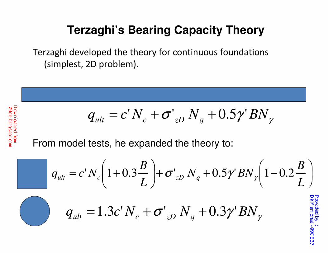
Terzaghi’s Bearing Capacity Theory
Terzaghi developed the theory for continuous foundations
(simplest, 2D problem).
γγσ BNNNcq qzDcult '5.0'' ++=
−++
+=
L
BBNN
L
BNcq qzDcult 2.01'5.0'3.01' γγσ
γγσ BNNNcq qzDcult '3.0''3.1 ++=
From model tests, he expanded the theory to:
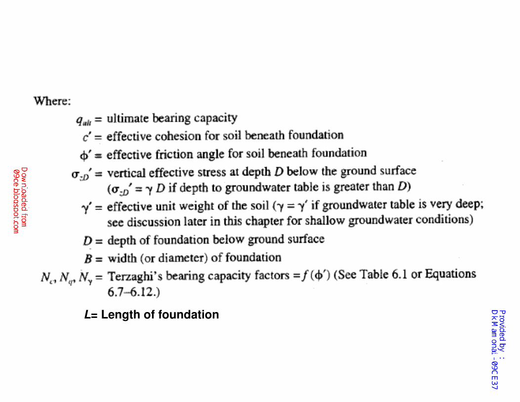
L= Length of foundation
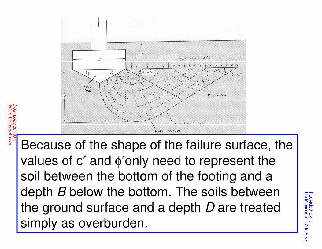
Because of the shape of the failure surface, the
values of c′ and φ′only need to represent the soil between the bottom of the footing and a depth B below the bottom. The soils between the ground surface and a depth D are treated simply as overburden.
�Terzaghi's formulas are presented in terms of
effective stresses. However, they also may be used in
a total stress analyses by substituting cT φT and σD
for c', φ', and σD ′
�If saturated undrained conditions exist, we may
conduct a total stress analysis with the shear strength
defined as cT= Su and φT= O. In this case, Nc = 5.7, Nq = 1.0, and Nγ = 0.0.
Key Points
Since Terzaghi neglected the shear strength of soils between the ground surface and a depth D, the shear surface stops at this depth and the overlying soil has been replaced with
the surcharge pressure σzD .
This approach is conservative, and is part of the reason for limiting the method to relatively shallow foundations (D < B).
Limitation for Terzaghi's Method
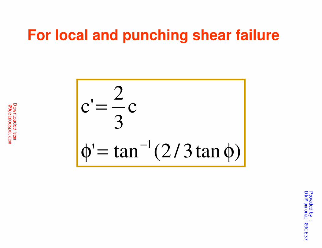
For local and punching shear failure
)tan3/2(tan'
c3
2'c
1 φ=φ
=
−
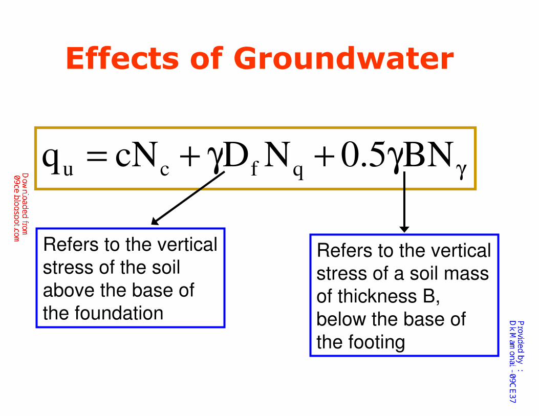
Effects of Groundwater
γγ+γ+= BN5.0NDcNq qfcu
Refers to the vertical
stress of the soil
above the base of
the foundation
Refers to the vertical
stress of a soil mass
of thickness B,
below the base of
the footing
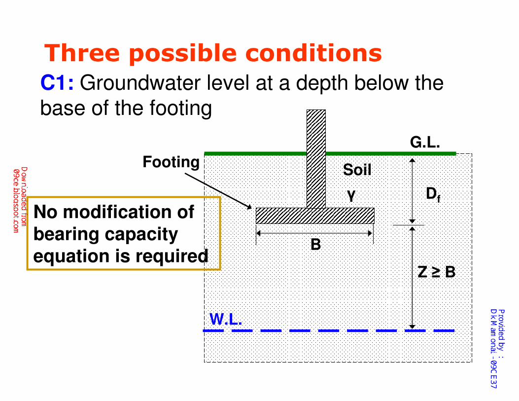
Three possible conditionsC1: Groundwater level at a depth below the base of the footing
G.L.
Soil
γ Df
B
Footing
W.L.
Z ≥ B
No modification of bearing capacity equation is required
Terzaghi’s Bearing Capacity Theory
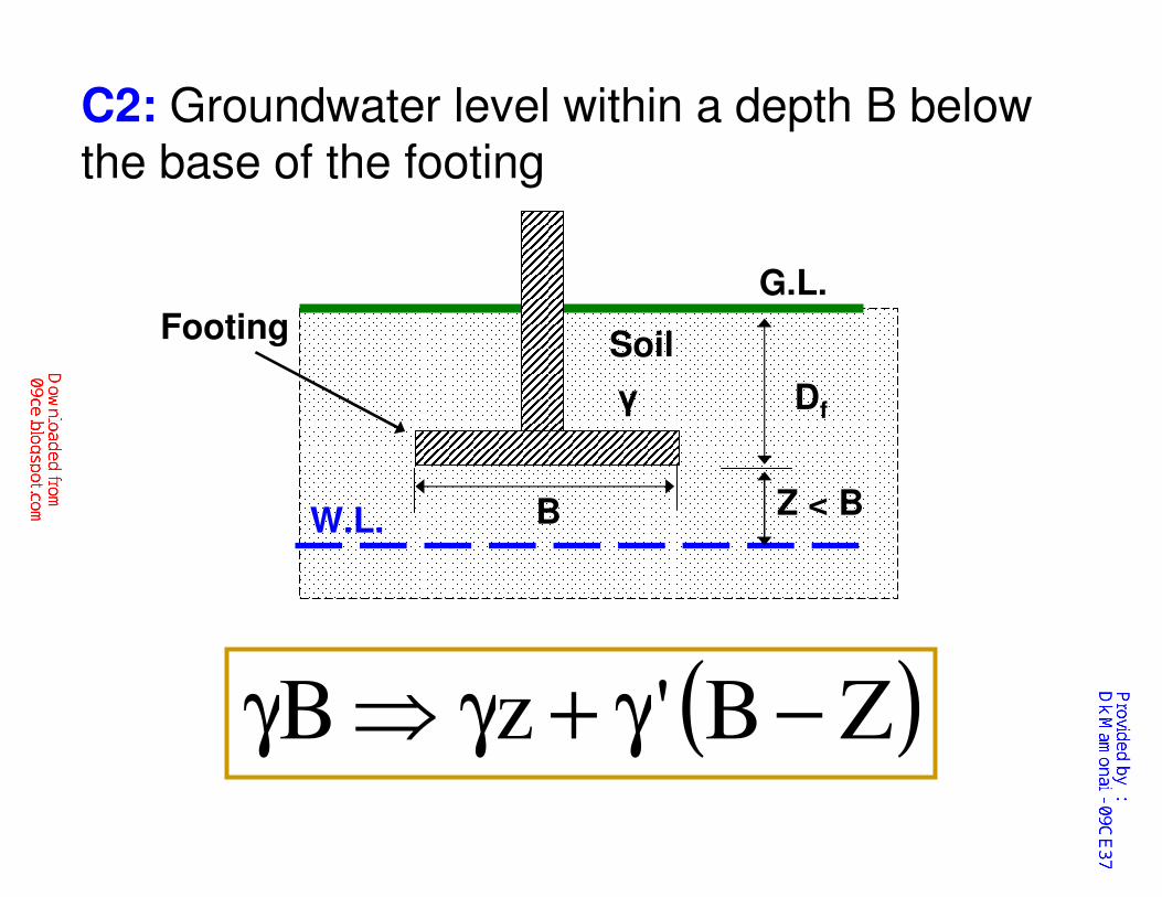
C2: Groundwater level within a depth B below the base of the footing
G.L.
Soil
γ Df
B
Footing
W.L.Z < B
( )ZB'zB −γ+γ⇒γ
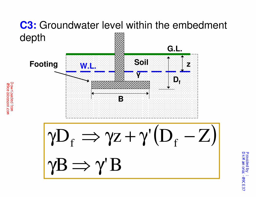
C3: Groundwater level within the embedment depth
G.L.
Soil
γDf
B
Footing W.L.
( )B'B
ZD'zD ff
γ⇒γ
−γ+γ⇒γ
z
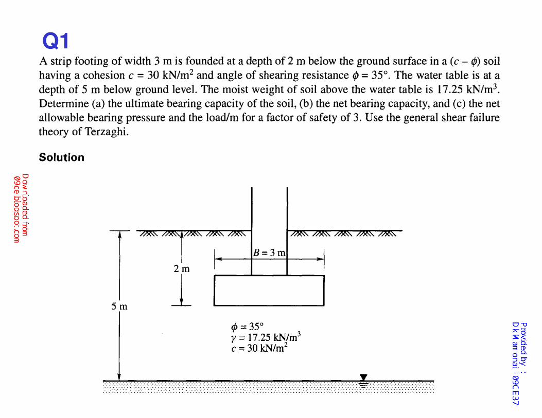
Q1
Q2. If the soil in Q1 fails by local shear failure,
determine the net safe bearing pressure.
Q3. If the water table in Q1 rises to the ground
level, determine the net safe bearing pressure of
the footing. Assume the saturated unit weight of the
soil γsat= 18.5 kN/m3
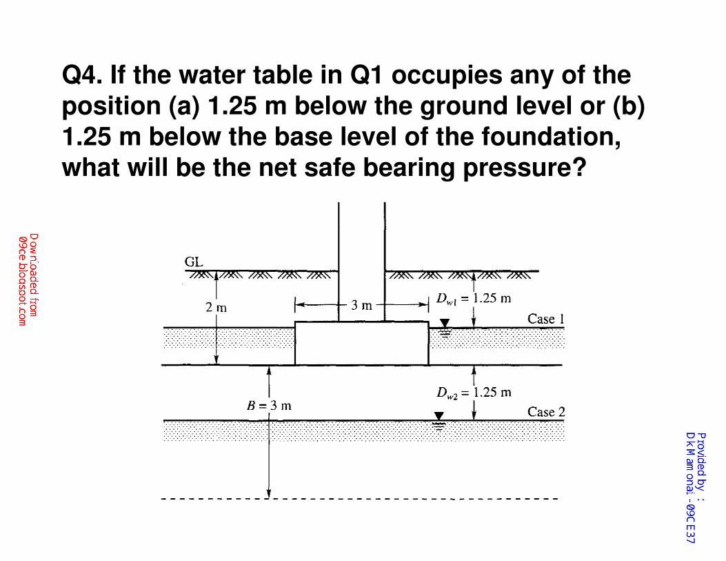
Q4. If the water table in Q1 occupies any of the
position (a) 1.25 m below the ground level or (b) 1.25 m below the base level of the foundation, what will be the net safe bearing pressure?
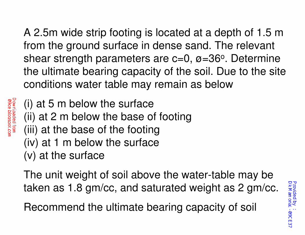
A 2.5m wide strip footing is located at a depth of 1.5 m
from the ground surface in dense sand. The relevant
shear strength parameters are c=0, ø=36o. Determine
the ultimate bearing capacity of the soil. Due to the site
conditions water table may remain as below
(i) at 5 m below the surface
(ii) at 2 m below the base of footing
(iii) at the base of the footing
(iv) at 1 m below the surface
(v) at the surface
The unit weight of soil above the water-table may be
taken as 1.8 gm/cc, and saturated weight as 2 gm/cc.
Recommend the ultimate bearing capacity of soil
Further Developments in Terzaghi Bearing Capacity Equation
�Meyerhof (1963)
�Hansen (1970)
�Vesic (1973)
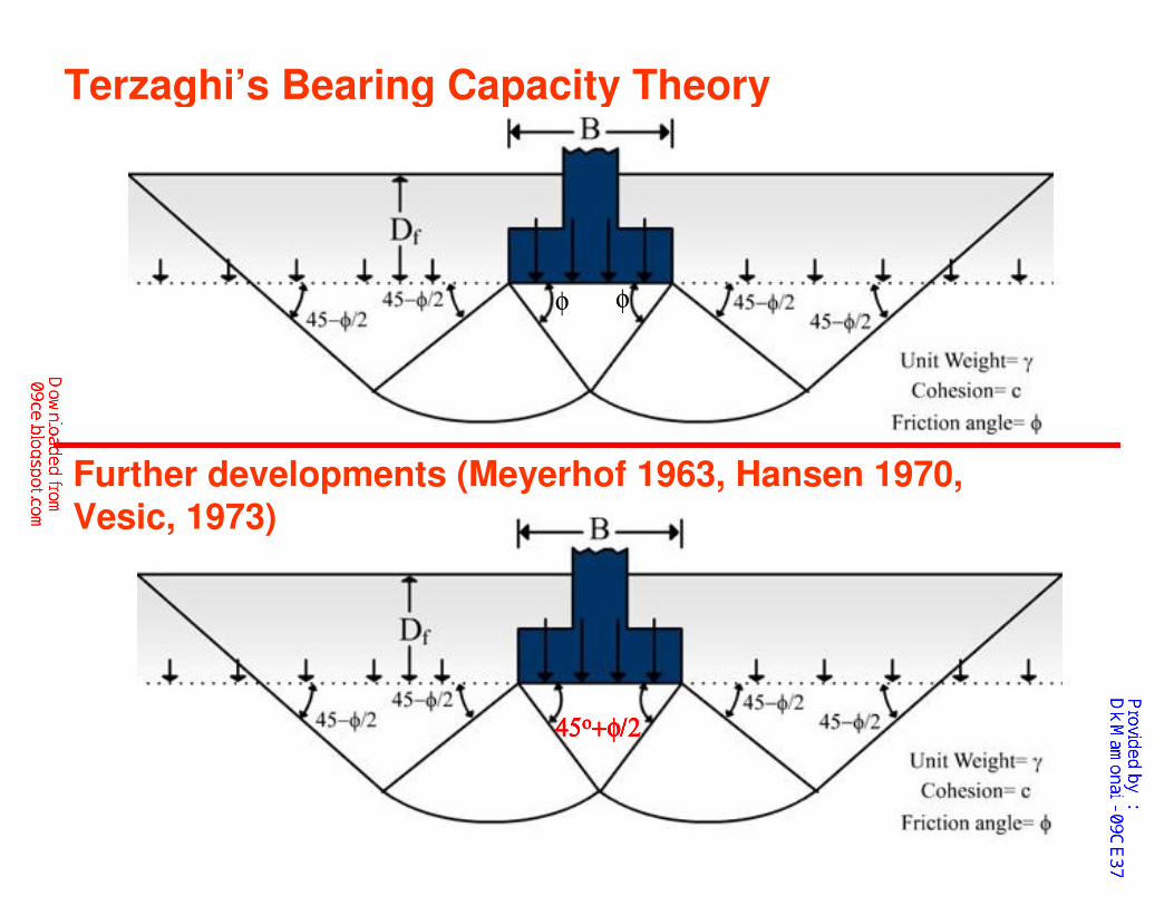
Terzaghi’s Bearing Capacity Theory
φ φ
45454545οοοο++++φφφφ/2/2/2/2
Further developments (Meyerhof 1963, Hansen 1970, Vesic, 1973)
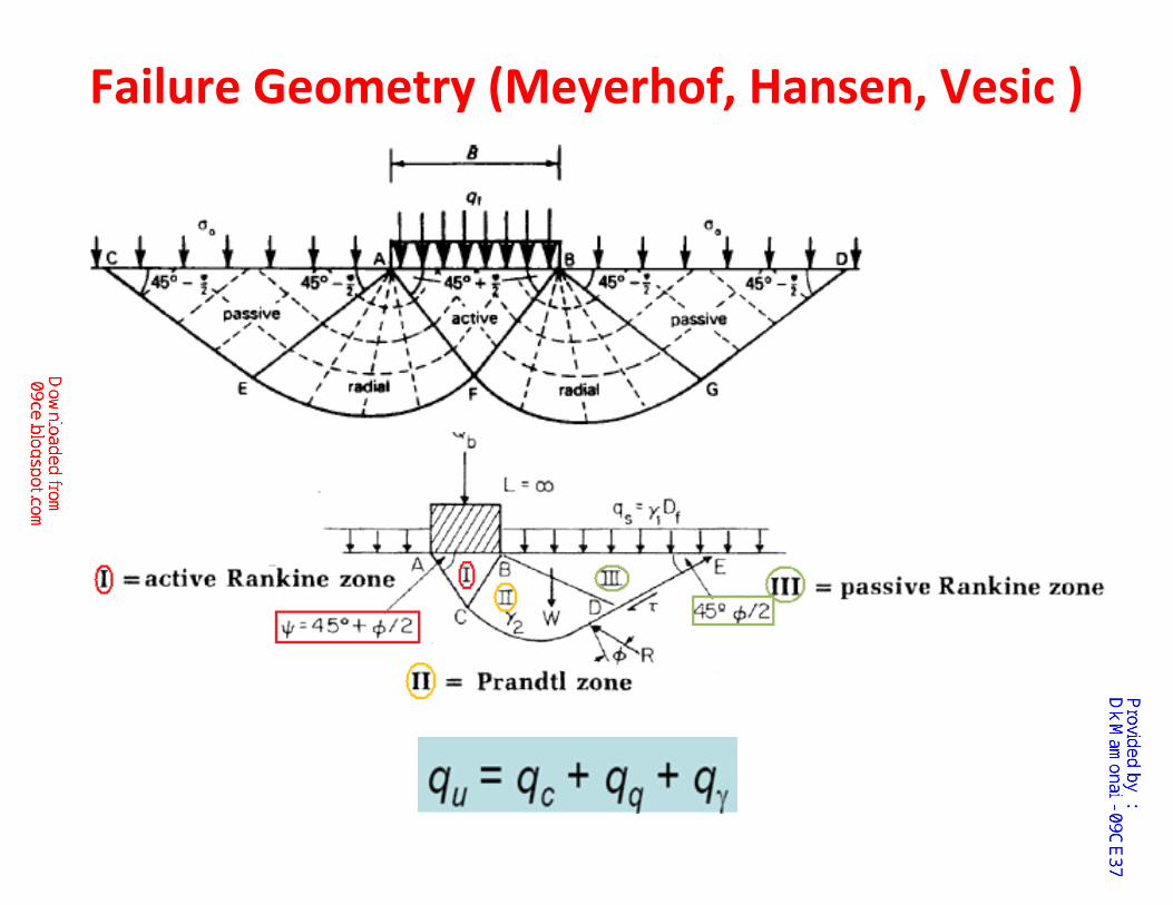
Failure Geometry (Meyerhof, Hansen, Vesic )
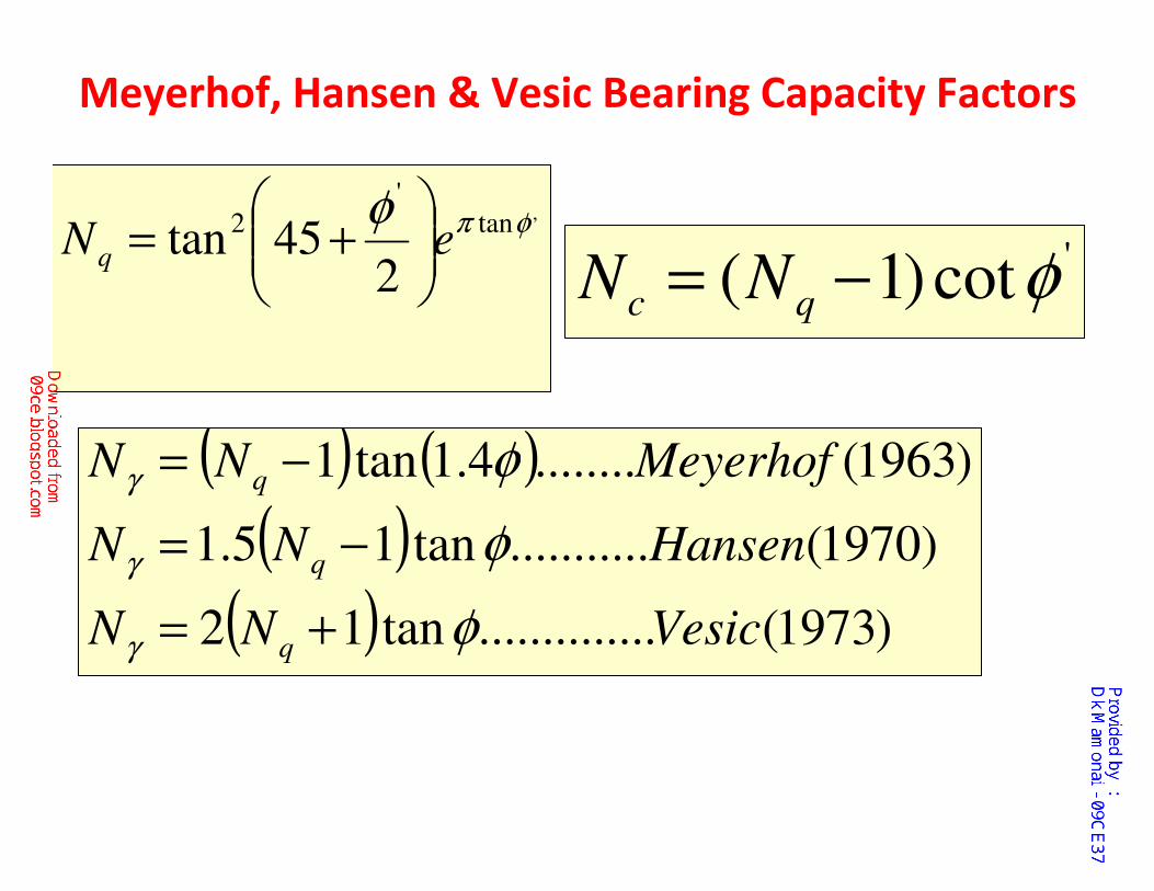
Meyerhof, Hansen & Vesic Bearing Capacity Factors
,tan'
2
245tan φπφ
eNq
+=
( ) ( )
( )( ) )1973(..............tan12
)1970(...........tan15.1
)1963(........4.1tan1
VesicNN
HansenNN
MeyerhofNN
q
q
q
φ
φ
φ
γ
γ
γ
+=
−=
−=
'cot)1( φ−= qc NN
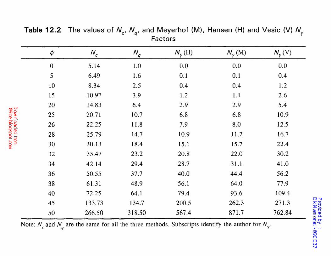
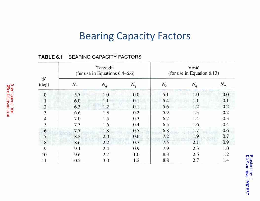
Bearing Capacity Factors
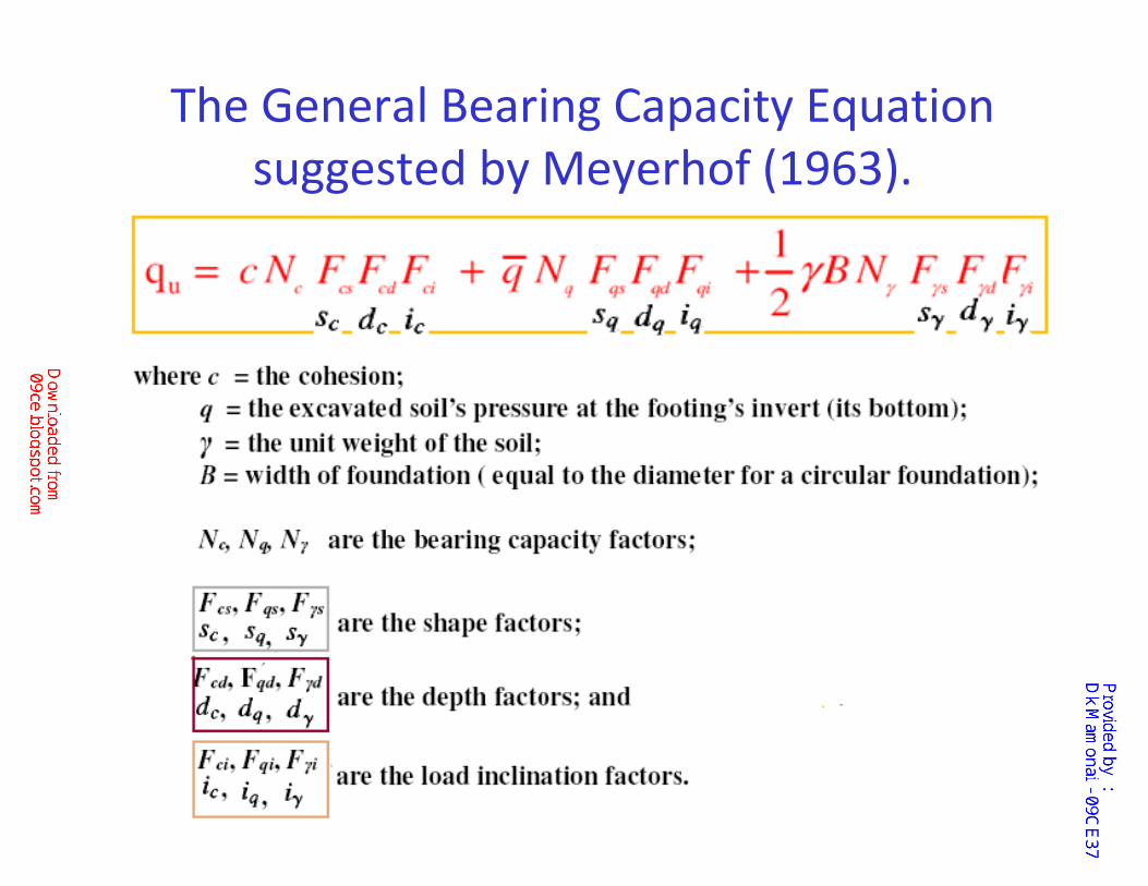
The General Bearing Capacity Equation
suggested by Meyerhof (1963).
Cont…..
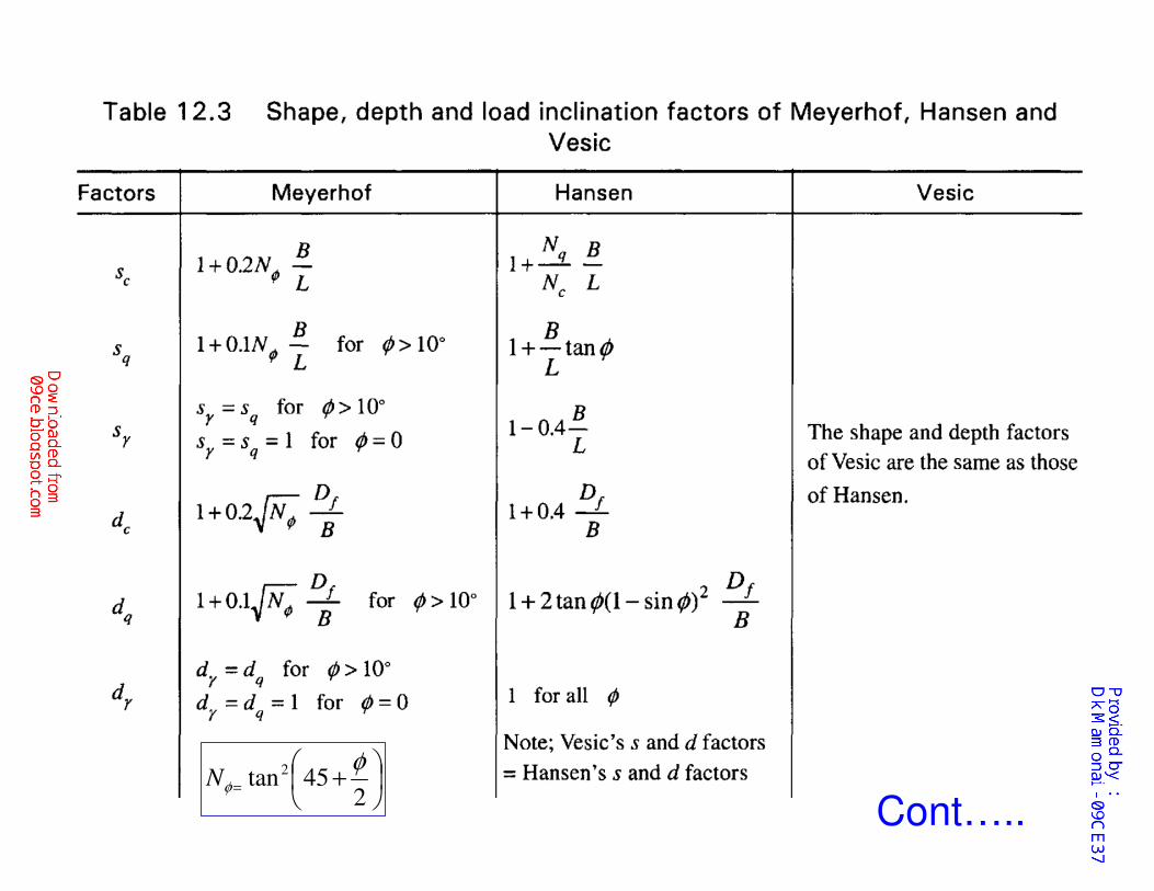
+=
245tan2 φ
φN
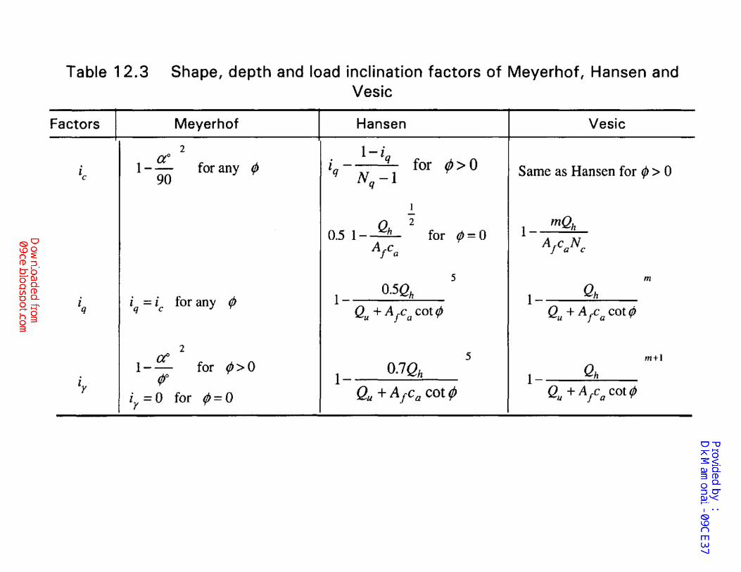
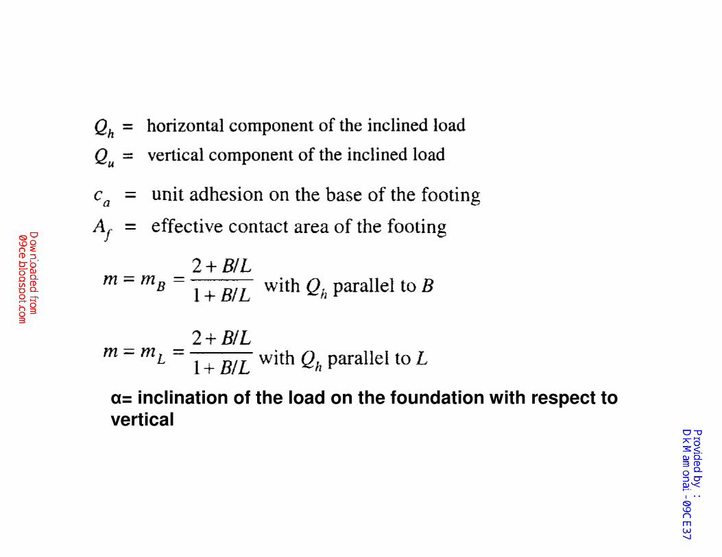
α= inclination of the load on the foundation with respect to vertical
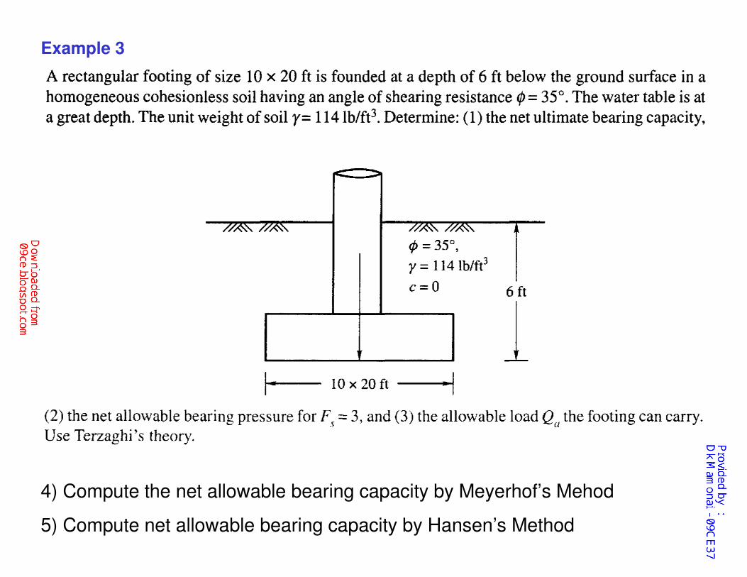
Example 3
4) Compute the net allowable bearing capacity by Meyerhof’s Mehod
5) Compute net allowable bearing capacity by Hansen’s Method
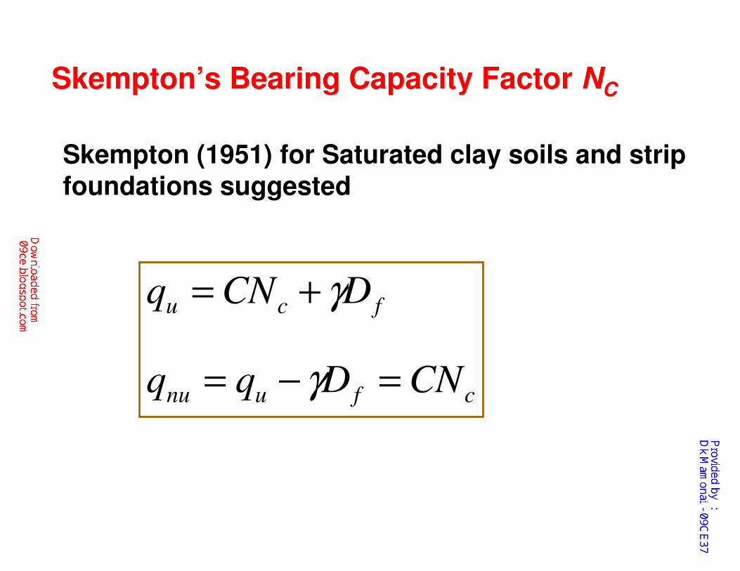
Skempton’s Bearing Capacity Factor NC
Skempton (1951) for Saturated clay soils and strip
foundations suggested
cfunu
fcu
CNDqq
DCNq
=−=
+=
γ
γ
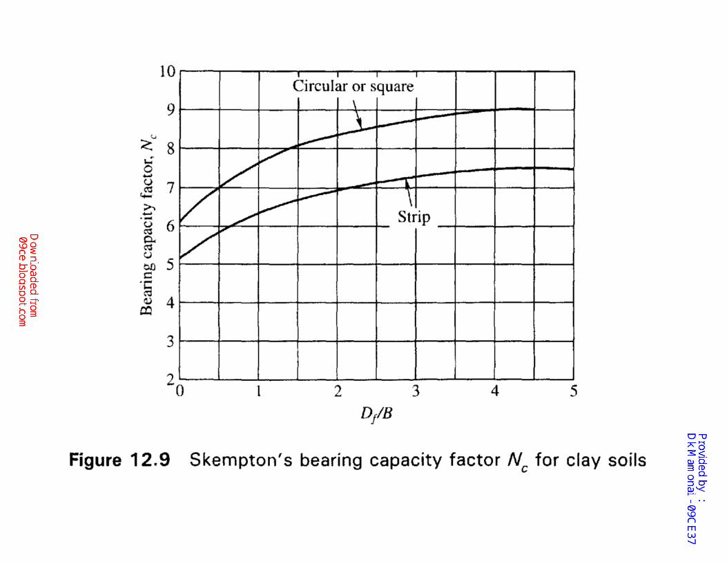
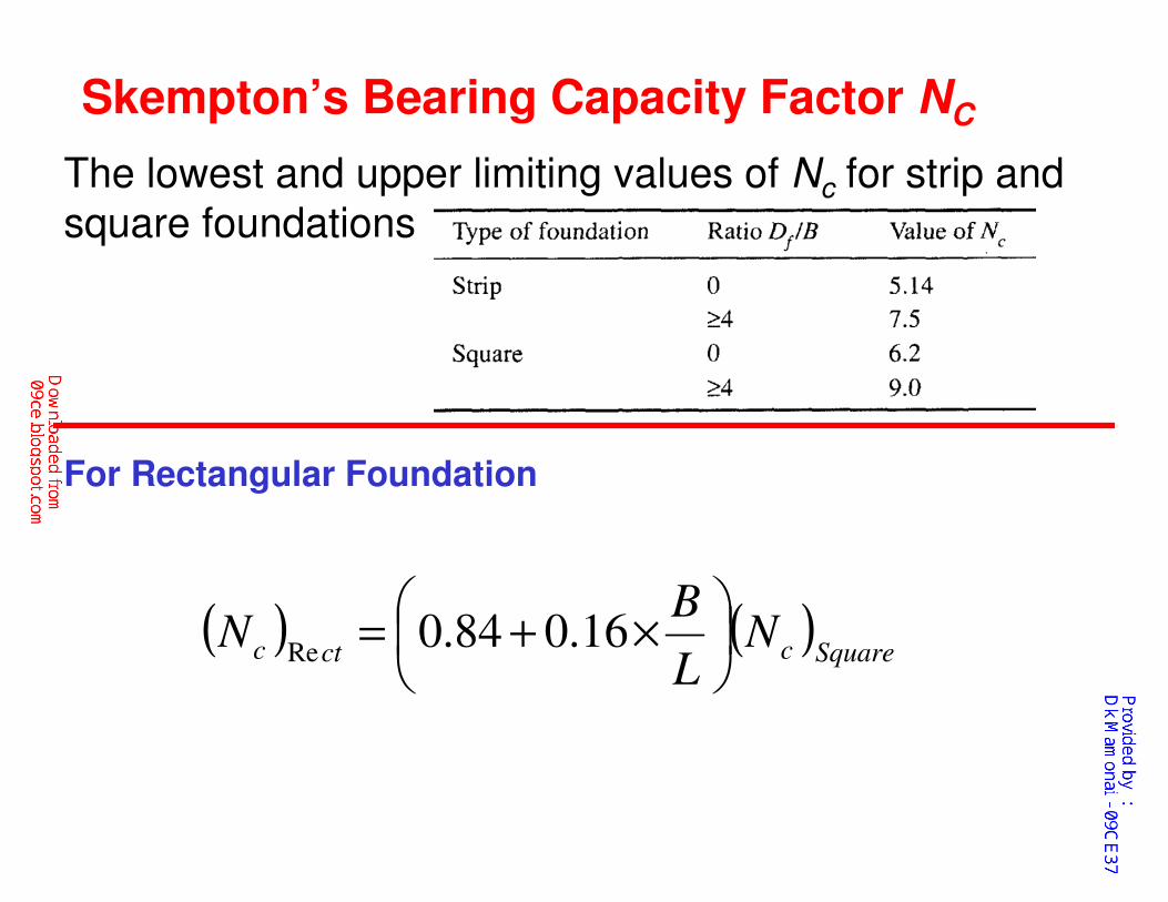
Skempton’s Bearing Capacity Factor NC
The lowest and upper limiting values of Nc for strip and
square foundations
For Rectangular Foundation
( ) ( )Squarecctc N
L
BN
×+= 16.084.0
Re


![Module 4 : Design of Shallow Foundations Lecture 17 ...€¦ · Module 4 : Design of Shallow Foundations Lecture 17 : Bearing capacity [ Section17.1 : Introduction ] 17. Bearing capacity](https://static.fdocuments.net/doc/165x107/5f0a26497e708231d42a4085/module-4-design-of-shallow-foundations-lecture-17-module-4-design-of-shallow.jpg)