6-B-6 6-B-7 6-B-8 Firewall · PDF fileFirewall Assembly Section 6-B-6, ... assembly manual is...
17
ZODIAC CH 650 Zenith Aircraft Company www.zenithair.com Firewall Assembly Section 6-B-6, 6-B-7, & 6-B-8 Page 1 of 17 Revision 1.0 (10/28/09) © 2009 Zenith Aircraft Co. Section 6-B-6, 6-B-7, & 6-B-8 Firewall Assembly This manual has been prepared for assembly of the firewall supplied with match drilled parts. This photo assembly manual is intended as a supplement to the drawings. If there is any discrepancy between this manual and the drawings, the drawings supersede this manual. For more information on building standards and allowable tolerances see “Construction Standards for Zenair Light Aircraft” available from Zenith Aircraft Company.
Transcript of 6-B-6 6-B-7 6-B-8 Firewall · PDF fileFirewall Assembly Section 6-B-6, ... assembly manual is...

ZODIAC CH 650
Zenith Aircraft Company www.zenithair.com
Firewall Assembly Section 6-B-6, 6-B-7, & 6-B-8 Page 1 of 17
Revision 1.0 (10/28/09) © 2009 Zenith Aircraft Co.
Section 6-B-6, 6-B-7, & 6-B-8 Firewall Assembly
This manual has been prepared for assembly of the firewall supplied with match drilled parts. This photo assembly manual is intended as a supplement to the drawings. If there is any discrepancy between this manual and the drawings, the drawings supersede this manual. For more information on building standards and allowable tolerances see “Construction Standards for Zenair Light Aircraft” available from Zenith Aircraft Company.

ZODIAC CH 650
Zenith Aircraft Company www.zenithair.com
Firewall Assembly Section 6-B-6, 6-B-7, & 6-B-8 Page 2 of 17
Revision 1.0 (10/28/09) © 2009 Zenith Aircraft Co.
Clamp the Firewall Bottom Stiffener to the bottom flange of the Firewall. The 22mm flange belongs on the bottom flange of the Firewall.
P/N: 6B6-2 Firewall P/N: 6B6-1 Firewall Bottom Stiffener
With a #40 drill bit, back drill through the Firewall into the Firewall Bottom Stiffener and Cleco. With a #30 drill bit, expand the holes and Cleco.

ZODIAC CH 650
Zenith Aircraft Company www.zenithair.com
Firewall Assembly Section 6-B-6, 6-B-7, & 6-B-8 Page 3 of 17
Revision 1.0 (10/28/09) © 2009 Zenith Aircraft Co.
Cleco the Firewall Top Stiffener to the Firewall. Wait to expand the holes until the Firewall Rear Reinforcement is installed.
P/N: 6B7-1 Firewall Top Stiffener
Cut a piece of L angle 520mm long. Position the L Angle on top of the Top Firewall Stiffener. Position the L Angle so there is 10mm edge distance for the holes at each end of the L Angle on the Firewall Top Stiffener. With a #40 drill bit, back drill through the Firewall Top Stiffener into the L Angle and Cleco. Expand the holes with a #20 drill bit and Cleco.

ZODIAC CH 650
Zenith Aircraft Company www.zenithair.com
Firewall Assembly Section 6-B-6, 6-B-7, & 6-B-8 Page 4 of 17
Revision 1.0 (10/28/09) © 2009 Zenith Aircraft Co.
Flip the Firewall over to drill the other flange of the L Angle. With a #40 drill bit, back drill through the Firewall into the L Angle and Cleco. Wait to expand the holes until the Firewall Rear Reinforcement is installed.
Mark a line from the start of the radius to 10mm down from the top of the large flange on the Firewall Side Stiffener. Trim the large flange of the Firewall Side Stiffener along the line. Draw a center line on the back of the large flange. Note: The center line should be marked on the opposite side than that shown above.
P/N: 6B6-3 Firewall Side Stiffener

ZODIAC CH 650
Zenith Aircraft Company www.zenithair.com
Firewall Assembly Section 6-B-6, 6-B-7, & 6-B-8 Page 5 of 17
Revision 1.0 (10/28/09) © 2009 Zenith Aircraft Co.
Position the Firewall Side Stiffener on the front of the Firewall. When the center line is visible through the predrilled hole for the Engine Mount Bolt, clamp the Firewall Side Stiffener to the Firewall. With a #40 drill bit, back drill through the Firewall into the Firewall Side Stiffener and Cleco.
Rotate the Firewall Side Stiffener until the center line is visible through the predrilled hole for the Lower Engine Mount Bolt and clamp the Firewall Side Stiffener to the Firewall. With a #40 drill bit, back drill through the Firewall into the Firewall Side Stiffener and Cleco.
ZODIAC CH 650
Zenith Aircraft Company www.zenithair.com
Firewall Assembly Section 6-B-6, 6-B-7, & 6-B-8 Page 6 of 17
Revision 1.0 (10/28/09) © 2009 Zenith Aircraft Co.
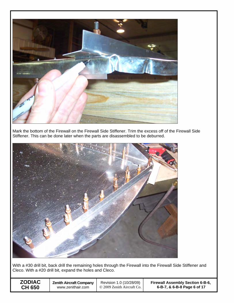
Mark the bottom of the Firewall on the Firewall Side Stiffener. Trim the excess off of the Firewall Side Stiffener. This can be done later when the parts are disassembled to be deburred.
With a #30 drill bit, back drill the remaining holes through the Firewall into the Firewall Side Stiffener and Cleco. With a #20 drill bit, expand the holes and Cleco.

ZODIAC CH 650
Zenith Aircraft Company www.zenithair.com
Firewall Assembly Section 6-B-6, 6-B-7, & 6-B-8 Page 7 of 17
Revision 1.0 (10/28/09) © 2009 Zenith Aircraft Co.
Cleco the Firewall Rear Reinforcement to the Firewall. The rivets are common for the Firewall Top Stiffener and the L Angle attached to it. With a #30 drill bit, expand the holes through the Rear Reinforcement into the Firewall, Top Stiffener, and L Angle and Cleco. With a #20 drill bit, expand the holes and Cleco.
P/N: 6B7-2 Firewall Rear Reinforcement
Cut a piece of L angle 543mm long and draw a center line down one flange. On the unmarked flange, measure up 15mm and place a mark. Trim the L angle along the mark so the L angle clears the bottom of the Firewall. Check: Be sure there will be sufficient edge distance on the L angle for the rivets at each end of the L angle.

ZODIAC CH 650
Zenith Aircraft Company www.zenithair.com
Firewall Assembly Section 6-B-6, 6-B-7, & 6-B-8 Page 8 of 17
Revision 1.0 (10/28/09) © 2009 Zenith Aircraft Co.
Position the L angles on the aft side of the Firewall. When the center line is visible through the predrilled holes in the Firewall, clamp the L angle to the Firewall. With a #40 drill bit, back drill through the Firewall into the L angle and Cleco. With a #30 drill bit, expand the holes and Cleco.
Cleco the Center Firewall Stiffener to the Firewall. With a #30 drill bit, expand the holes and Cleco.
P/N: 6B8-7 Center Firewall Stiffener

ZODIAC CH 650
Zenith Aircraft Company www.zenithair.com
Firewall Assembly Section 6-B-6, 6-B-7, & 6-B-8 Page 9 of 17
Revision 1.0 (10/28/09) © 2009 Zenith Aircraft Co.
P/N: 6B8-1 Gear Gusset
Slightly bend the ends of the top flange. This is so the flange of the Gear Gusset will set in the radius of the Top Firewall Stiffener.

ZODIAC CH 650
Zenith Aircraft Company www.zenithair.com
Firewall Assembly Section 6-B-6, 6-B-7, & 6-B-8 Page 10 of 17
Revision 1.0 (10/28/09) © 2009 Zenith Aircraft Co.
Position the Gear Gusset on the Center Firewall Stiffener and the Top Stiffener. The top flange of the Gear Gusset should set against the web of the Top Stiffener. The aft edge of the Gear Gusset should be parallel to the Firewall and slightly offset from the web of the Firewall. Clamp the Gear Gusset to the Center Firewall Stiffener. With a #40 drill bit, back drill through the Gear Gusset into the Center Firewall Stiffener and Cleco. Then with a #20 drill bit expand the holes and Cleco. Check: Make sure there is proper edge distance on the holes through the Gear Gusset into the Center Firewall Stiffener.
With a # 40 drill bit, back drill through the Top Stiffener into the Gear Gusset and Cleco. With a #20, expand the holes and Cleco.

ZODIAC CH 650
Zenith Aircraft Company www.zenithair.com
Firewall Assembly Section 6-B-6, 6-B-7, & 6-B-8 Page 11 of 17
Revision 1.0 (10/28/09) © 2009 Zenith Aircraft Co.
With an Angle Drill and a #40 drill bit, back drill the hole for the Bungee Pin in the Center Firewall Stiffener into the Gear Gusset.
Position the Firewall Stiffener Doubler inside the Center Firewall Stiffener and clamp in position. The bottom of the Doubler should be flush with the bottom of the Center Firewall Stiffener. With a #40 drill bit, back drill through the Center Firewall Stiffener into the Doubler and Cleco. Then expand the holes with a #30 drill bit and Cleco.
P/N: 6B8-2 Firewall Stiffener Doubler Note: The photo to the left does not have the holes predrilled in the Center Firewall Stiffener. The part is supplied predrilled in the kit.

ZODIAC CH 650
Zenith Aircraft Company www.zenithair.com
Firewall Assembly Section 6-B-6, 6-B-7, & 6-B-8 Page 12 of 17
Revision 1.0 (10/28/09) © 2009 Zenith Aircraft Co.
Expand the holes for the Bungee Pin to 5/8” diameter. A Step Drill works very well to do this.
Layout 4 rivets around the hole for the Bungee Pin. Maintain at least minimum edge distance from each edge, including the hole for the Bungee Pin. With a #40 drill bit, drill the holes and Cleco. With a #20 drill bit, expand the holes and Cleco. Countersink the holes for these rivets. When the rivets are set be sure to use a flat nose piece so the rivet heads won’t chafe the Bungee.

ZODIAC CH 650
Zenith Aircraft Company www.zenithair.com
Firewall Assembly Section 6-B-6, 6-B-7, & 6-B-8 Page 13 of 17
Revision 1.0 (10/28/09) © 2009 Zenith Aircraft Co.
Position the Slide Cover on the Firewall against the Center Firewall Stiffener and clamp the Slide Cover to the Firewall.
Check: Be sure there is adequate edge distance for the holes in the Slide Cover before drilling.
With a #40 drill bit, back drill through the holes in the Firewall into the Slide Cover and Cleco. With a #30 drill bit, expand the holes and Cleco.
P/N: 6B7-4 Slide Cover
Mark the center of the Top Stiffener and the center of the Forward Gusset. Mark a line 10mm from the top and bottom edges of the Gusset. Layout seven rivet locations on each line.
P/N: 6B8-10 Forward Gusset

ZODIAC CH 650
Zenith Aircraft Company www.zenithair.com
Firewall Assembly Section 6-B-6, 6-B-7, & 6-B-8 Page 14 of 17
Revision 1.0 (10/28/09) © 2009 Zenith Aircraft Co.
Align the center line on the Forward Gusset with the center line of Top Stiffener. Clamp the Forward Gusset to the Top Stiffener when the bottom of the Gusset is flush with the bottom of the Top Stiffener.
Center the Upper Angle on the Top Stiffener. Check the final hole at each end to ensure there is 10mm edge distance. When the Upper Angle is correctly positioned, clamp the Upper Angle to the Forward Gusset.
P/N: 6B8-11 Upper Angle
ZODIAC CH 650
Zenith Aircraft Company www.zenithair.com
Firewall Assembly Section 6-B-6, 6-B-7, & 6-B-8 Page 15 of 17
Revision 1.0 (10/28/09) © 2009 Zenith Aircraft Co.
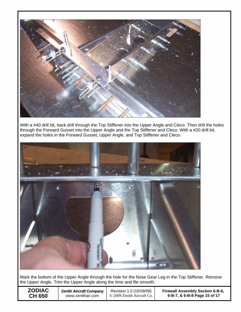
With a #40 drill bit, back drill through the Top Stiffener into the Upper Angle and Cleco. Then drill the holes through the Forward Gusset into the Upper Angle and the Top Stiffener and Cleco. With a #20 drill bit, expand the holes in the Forward Gusset, Upper Angle, and Top Stiffener and Cleco.
Mark the bottom of the Upper Angle through the hole for the Nose Gear Leg in the Top Stiffener. Remove the Upper Angle. Trim the Upper Angle along the time and file smooth.

ZODIAC CH 650
Zenith Aircraft Company www.zenithair.com
Firewall Assembly Section 6-B-6, 6-B-7, & 6-B-8 Page 16 of 17
Revision 1.0 (10/28/09) © 2009 Zenith Aircraft Co.
File a radius on to the front edge of the Upper Bearing to match the radius of the front flange of the Top Stiffener.
P/N: 6B8-6 Upper Bearing
Use the Nose Gear Leg to properly position the Upper Bearing, the Nose Gear Leg should not make contact with the Top Stiffener. Clamp the Upper Bearing to the Top Stiffener. With a #40 drill bit, back drill through the Top Stiffener into the Upper Bearing and Cleco. Expand the holes to 3/16” and Cleco. Note: The Upper Bearing does not have to be drilled at this time and can be installed with the Nose Gear Leg installation.

ZODIAC CH 650
Zenith Aircraft Company www.zenithair.com
Firewall Assembly Section 6-B-6, 6-B-7, & 6-B-8 Page 17 of 17
Revision 1.0 (10/28/09) © 2009 Zenith Aircraft Co.
Draw a center line on the bottom flange of the Side Brace. Position the Side Brace on top of the Top Stiffener with 10mm edge distance on the end holes and clamp the Side Brace in position. With a #40 drill bit, back drill through the Top Stiffener into the Side Brace and Cleco. With a #20 drill bit, expand the holes and Cleco.
P/N: 6B7-3 Side Brace
Disassemble the Firewall, deburr the parts, reassemble, and rivet the Firewall together.