6 Automatic Extinguishing - CFAA · 6 Automatic Extinguishing ... The most commonly used automatic...
50
Automatic Extinguishing 185 Fire Safety Guide / © Siemens Switzerland Ltd 6 Automatic Extinguishing 6.1 Summary .............................................................................................. 187 6.2 Basics................................................................................................... 188 6.2.1 Extinguishing Agents ............................................................................ 188 6.2.2 Protection Categories ........................................................................... 189 6.2.3 Protection Objective .............................................................................. 190 6.3 Fire Physics ......................................................................................... 191 6.3.1 The Three Elements of Fire .................................................................. 191 6.3.2 Combustion Process ............................................................................. 192 6.3.3 Principles of Fire Extinguishing ............................................................. 193 6.3.4 Flooding Time and Holding Time .......................................................... 195 6.4 Water Extinguishing Systems ........................................................... 196 6.4.1 Water as an Extinguishing Agent .......................................................... 196 6.4.2 Sprinkler Systems ................................................................................. 196 6.4.3 Water Spray Extinguishing Systems ..................................................... 203 6.4.4 Water Fog Extinguishing Systems ........................................................ 204 6.5 Foam Extinguishing Systems ............................................................ 205 6.5.1 Foam as an Extinguishing Agent .......................................................... 205 6.5.2 Foam Types .......................................................................................... 205 6.5.3 System Setup and Function .................................................................. 207 6.6 Powder Extinguishing Systems ........................................................ 210 6.7 Gas Extinguishing Systems............................................................... 211 6.7.1 Natural Gases ....................................................................................... 211 6.7.2 Chemical Extinguishing Gases ............................................................. 213 6.7.3 System technology................................................................................ 217 6.7.4 Water Fog Systems as a Replacement for Gas Extinguishing Systems?.222 6.8 System Integration.............................................................................. 229 6.8.1 Location of the Fire Extinguishing Control Unit..................................... 232 6.8.2 Power Supply ........................................................................................ 232 6.8.3 Alarm Triggering.................................................................................... 233 6.9 Maintenance and Servicing................................................................ 234 6.10 Profitability and System Evaluation.................................................. 235
Transcript of 6 Automatic Extinguishing - CFAA · 6 Automatic Extinguishing ... The most commonly used automatic...
Automatic Extinguishing
185
Fire Safety Guide / © Siemens Switzerland Ltd
6 Automatic Extinguishing 6.1 Summary..............................................................................................187 6.2 Basics...................................................................................................188 6.2.1 Extinguishing Agents ............................................................................188 6.2.2 Protection Categories ...........................................................................189 6.2.3 Protection Objective..............................................................................190 6.3 Fire Physics .........................................................................................191 6.3.1 The Three Elements of Fire ..................................................................191 6.3.2 Combustion Process.............................................................................192 6.3.3 Principles of Fire Extinguishing.............................................................193 6.3.4 Flooding Time and Holding Time..........................................................195 6.4 Water Extinguishing Systems ...........................................................196 6.4.1 Water as an Extinguishing Agent..........................................................196 6.4.2 Sprinkler Systems .................................................................................196 6.4.3 Water Spray Extinguishing Systems.....................................................203 6.4.4 Water Fog Extinguishing Systems........................................................204 6.5 Foam Extinguishing Systems............................................................205 6.5.1 Foam as an Extinguishing Agent ..........................................................205 6.5.2 Foam Types ..........................................................................................205 6.5.3 System Setup and Function..................................................................207 6.6 Powder Extinguishing Systems ........................................................210 6.7 Gas Extinguishing Systems...............................................................211 6.7.1 Natural Gases .......................................................................................211 6.7.2 Chemical Extinguishing Gases .............................................................213 6.7.3 System technology................................................................................217 6.7.4 Water Fog Systems as a Replacement for Gas Extinguishing Systems?.222 6.8 System Integration..............................................................................229 6.8.1 Location of the Fire Extinguishing Control Unit.....................................232 6.8.2 Power Supply ........................................................................................232 6.8.3 Alarm Triggering....................................................................................233 6.9 Maintenance and Servicing................................................................234 6.10 Profitability and System Evaluation..................................................235
Automatic Extinguishing
187
Fire Safety Guide / © Siemens Switzerland Ltd
6.1 Summary
Automatic extinguishing systems shall either extinguish or prevent incipient fires in order to protect objects, rooms or entire buildings from fires and their conse-quences. The extinguishing agents used for this purpose are liquid (water), two-phase (foam), solid (powder) or gaseous (gases). Depending on the extinguishing agent, heat and/or oxygen is displaced from the fire, which means separated from the fuel. The extinguishing or suppressive effect begins with the flooding time and ends after expiry of the holding time. Intervention and automatic extinguishing must be harmonized accordingly. Water as the most frequently used and most widely distributed extinguishing agent is used in different sprinkler systems as well as in water spray and water fog extin-guishing systems. While the activation of sprinkler systems is mostly temperature-sensitive, other extinguishing systems generally require the activation by automatic fire detectors. By means of various foam generators and by adding compressed air in different concentrations, a wide array of extinguishing foams can be generated, applied in different areas and situations. In contrast, powder extinguishing systems are rarely used, as they are only advantageous in specific situations. Gas extinguishing systems use either natural gases or chemical extinguishing gases. While natural gases mainly displace oxygen, chemical extinguishing gases actively intervene in the combustion process. The best-known chemical extinguish-ing gases are halons, which have been banned for reasons of environmental protection. However, the environmental compatibility of advanced chemical extin-guishing gases applied today is beyond controversy. Extinguishing gases are stored in pressurized containers. The system layout and especially the correct discharge of the extinguishing agent under sufficient pres-sure is decisive for the correct functioning of the extinguishing system – even today, this can still not be taken for granted.
To select the best suited extinguishing method, the correct system layout and the optimum integration of the extinguishing system into the building management system requires experience and knowledge. If these prerequisites are matched, the system’s fire protection effect will be very high and in compliance with the objectives.
Extinguishing is a crucial part of an integral protection concept
Automatic Extinguishing
188
Fire Safety Guide / © Siemens Switzerland Ltd
6.2 Basics
The industrial development, which took place particularly during the second half of the 19th century, promoted the concentration of production processes. Instead of the small handicrafts enterprises, industrial companies now produced goods me-chanically, with the aid of large-scale facilities in accordingly voluminous production halls. This process automatically lead to a massive increase of fire risk, which due to their size, could no longer be contained with conventional, manual methods. This environment was the beginning of the first technical extinguishing installations. The pioneers of these extinguishing systems were mills, usually built in wooden constructions that were several stories high. In these mills, widely ramified piping systems leading to every room and provided with simple bore holes were installed. In case of fire, water could be fed through these bore holes. The first automatic extinguishing systems based on this concept were so-called “sprinkler systems” in which the bore holes were replaced by sealed heads with heat-sensitive activation elements. Today, these sprinkler systems are still the most widely distributed extinguishing systems worldwide. Later, other solutions with foam, powder or different gases were developed, especially for fire risks for which water was not the optimum solution. Today, a variety of possible solutions is available, distinguished according to their extinguishing agents, protection concept and protection objective. Due to scientifi-cally based research, efficient systems are available today, providing rapid extin-guishing when used appropriately.
6.2.1 Extinguishing Agents
The following extinguishing agents are internationally known and available today: − water − gases − powder − foam Water continues to be the most widely spread and best-known extinguishing agent. The most commonly used automatic system using water is the sprinkler system. These systems are employed in almost all fields of industry, larger business enter-prises, department stores, garages, meeting places, schools, hospitals, hotels, airports, etc. In addition to the sprinklers, automatically activated water spray extinguishing systems are available as well. Since the late 1990s, water is also used in systems operating with higher pressures, thus generating smaller droplets. These so-called water fog systems or water spray systems provide the extinguish-ing effect of “classic” water extinguishing systems and are consuming considerably less water while working equally reliably. In the course of this section, this system type will be described in detail.
Automatic Extinguishing
189
Fire Safety Guide / © Siemens Switzerland Ltd
During decades, carbon dioxide (CO2) and halons were virtually the only known extinguishing gases. As a consequence of the Montreal Protocol of 1987, halons were outlawed as extinguishing gas, and industry reacted by developing alternative solutions. This led to the use of other natural gases as extinguishing agents: To-day, nitrogen (N2) and argon (Ar) are the most important natural extinguishing gases apart from CO2. Furthermore, compounds of these three natural gases are available as well. Other chemical alternatives to halons have been developed. The most significant group of chemical extinguishing gases not harmful to the ozone layer are the chlorofluorocarbons (CFC), their best-known representative being HFC227ea, marketed among others by Great Lakes under the name of HFC227ea. Lately, the chemical extinguishing agent Novec™ 1230 has been commercially available, an agent that neither destroys the ozone layer nor essentially contributes to the greenhouse effect. While powder extinguishing systems are scarcely used due to considerable conse-quential damage (corrosion!), foam extinguishing systems for the protection of chemical and tank storage facilities are widely spread. In Germany, for example, 60% of all automatic extinguishing systems are sprinkler systems, 35% are gas extinguishing systems and the remaining 5% account for other system types.
6.2.2 Protection Categories
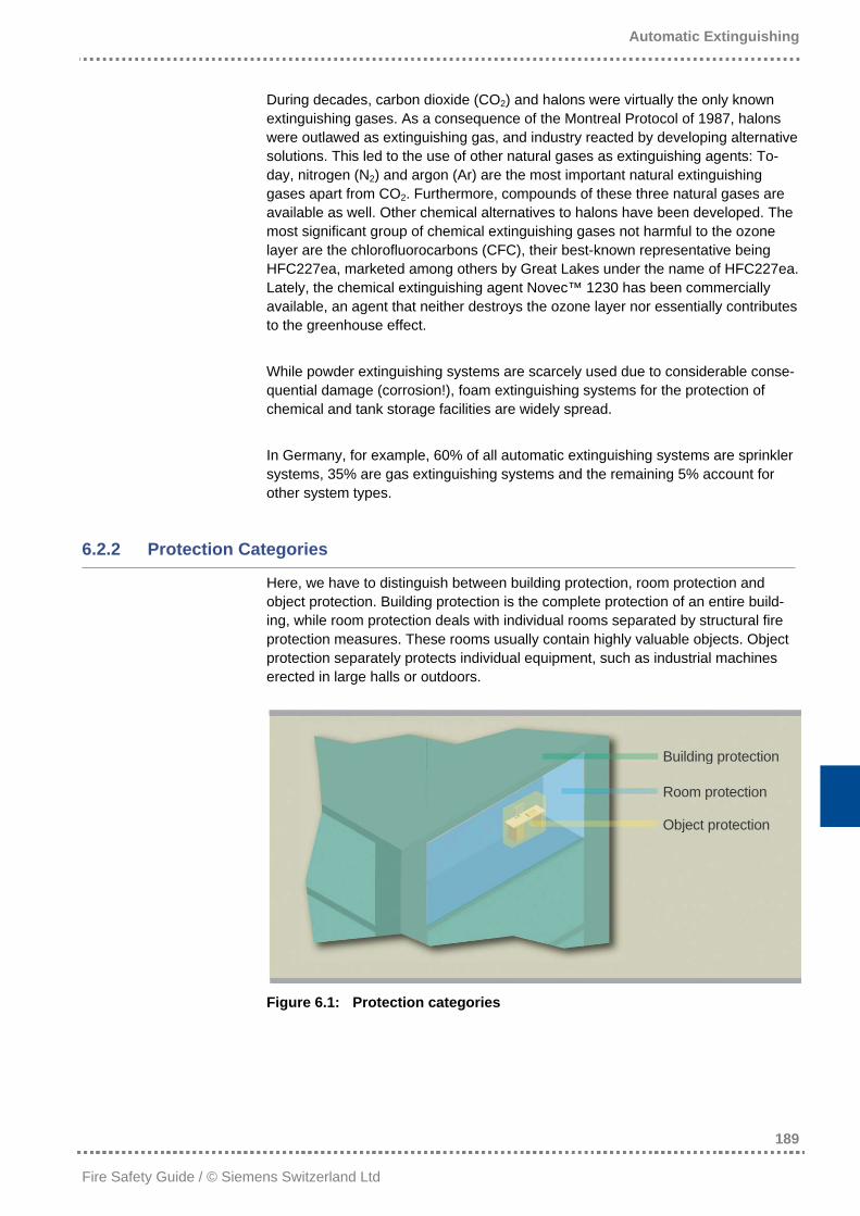
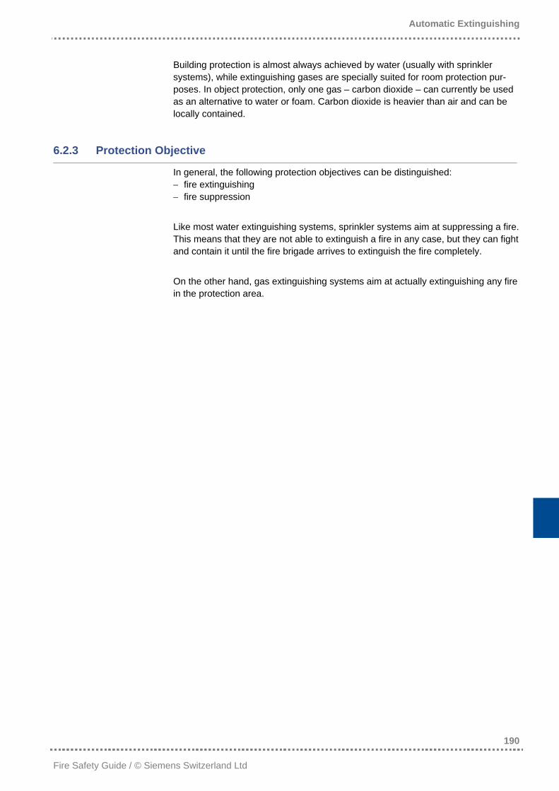
Here, we have to distinguish between building protection, room protection and object protection. Building protection is the complete protection of an entire build-ing, while room protection deals with individual rooms separated by structural fire protection measures. These rooms usually contain highly valuable objects. Object protection separately protects individual equipment, such as industrial machines erected in large halls or outdoors.
Figure 6.1: Protection categories
Building protection
Room protection
Object protection
Automatic Extinguishing
190
Fire Safety Guide / © Siemens Switzerland Ltd
Building protection is almost always achieved by water (usually with sprinkler systems), while extinguishing gases are specially suited for room protection pur-poses. In object protection, only one gas – carbon dioxide – can currently be used as an alternative to water or foam. Carbon dioxide is heavier than air and can be locally contained.
6.2.3 Protection Objective
In general, the following protection objectives can be distinguished: − fire extinguishing − fire suppression Like most water extinguishing systems, sprinkler systems aim at suppressing a fire. This means that they are not able to extinguish a fire in any case, but they can fight and contain it until the fire brigade arrives to extinguish the fire completely. On the other hand, gas extinguishing systems aim at actually extinguishing any fire in the protection area.
Automatic Extinguishing
191
Fire Safety Guide / © Siemens Switzerland Ltd
6.3 Fire Physics
The objective of this section is to provide an in-depth overview of the physical and chemical processes, specifically looking at the different possibilities of fire extin-guishing.
6.3.1 The Three Elements of Fire
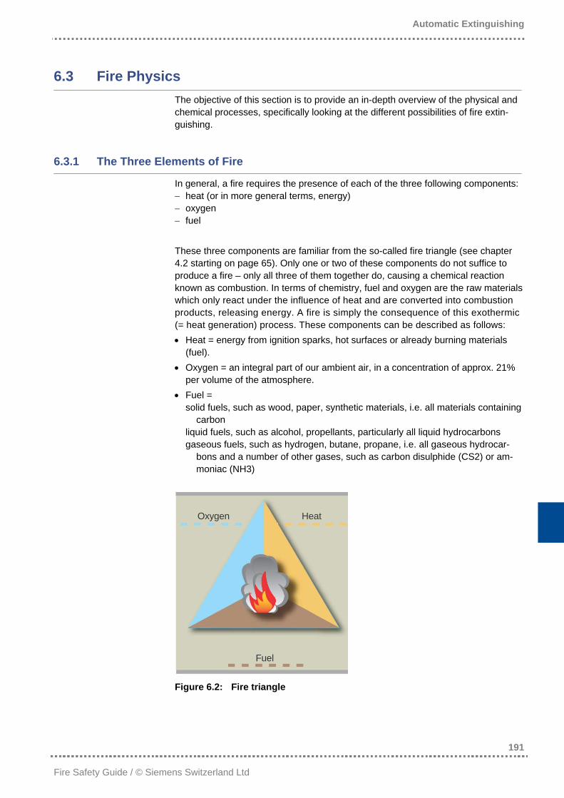
In general, a fire requires the presence of each of the three following components: − heat (or in more general terms, energy) − oxygen − fuel These three components are familiar from the so-called fire triangle (see chapter 4.2 starting on page 65). Only one or two of these components do not suffice to produce a fire – only all three of them together do, causing a chemical reaction known as combustion. In terms of chemistry, fuel and oxygen are the raw materials which only react under the influence of heat and are converted into combustion products, releasing energy. A fire is simply the consequence of this exothermic (= heat generation) process. These components can be described as follows: • Heat = energy from ignition sparks, hot surfaces or already burning materials
(fuel). • Oxygen = an integral part of our ambient air, in a concentration of approx. 21%
per volume of the atmosphere. • Fuel =
solid fuels, such as wood, paper, synthetic materials, i.e. all materials containing carbon
liquid fuels, such as alcohol, propellants, particularly all liquid hydrocarbons gaseous fuels, such as hydrogen, butane, propane, i.e. all gaseous hydrocar-
bons and a number of other gases, such as carbon disulphide (CS2) or am-moniac (NH3)
Figure 6.2: Fire triangle
HeatOxygen
Fuel
Automatic Extinguishing
192
Fire Safety Guide / © Siemens Switzerland Ltd
The specific reaction steps of decomposition occur sequentially but partly also in parallel to the reaction steps of the synthesis (the combination of individual atoms to new molecules). This so-called chain reaction is the core of the combustion process, which is triggered by the three components heat, oxygen and fuel and is maintained as long as all three components are present. A combustion process is always exothermic, thus producing heat – this is one of the reasons for the dynam-ics of fire: It grows continuously as oxygen and fuel are available in almost unlim-ited volumes at the beginning of the process.
6.3.2 Combustion Process
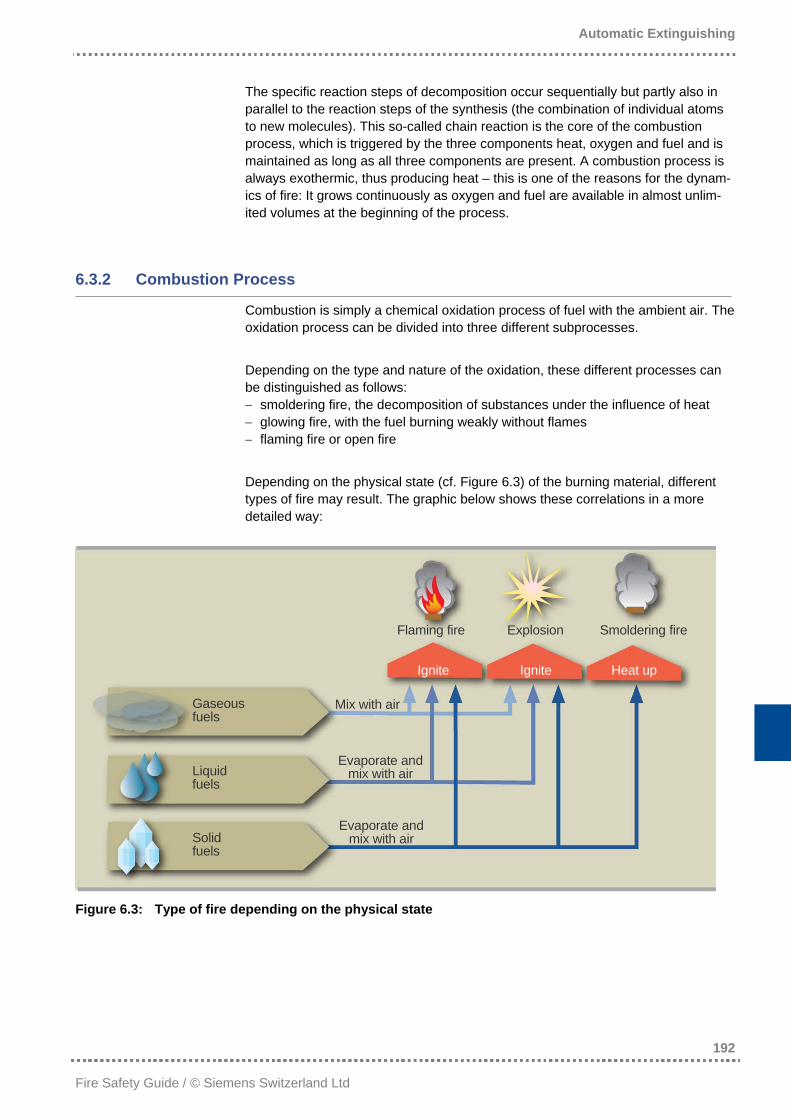
Combustion is simply a chemical oxidation process of fuel with the ambient air. The oxidation process can be divided into three different subprocesses. Depending on the type and nature of the oxidation, these different processes can be distinguished as follows: − smoldering fire, the decomposition of substances under the influence of heat − glowing fire, with the fuel burning weakly without flames − flaming fire or open fire Depending on the physical state (cf. Figure 6.3) of the burning material, different types of fire may result. The graphic below shows these correlations in a more detailed way:
Flaming fire Explosion Smoldering fire
Ignite Ignite Heat up
Gaseous fuels
Mix with air
Evaporate and mix with air Liquid
fuels
Evaporate and mix with air Solid
fuels
Figure 6.3: Type of fire depending on the physical state
Automatic Extinguishing
193
Fire Safety Guide / © Siemens Switzerland Ltd
6.3.3 Principles of Fire Extinguishing
In accordance with the three components of fire, there are three fundamentally different principles how a fire can be extinguished. Each of these three principles aims at one of the three fire components.
6.3.3.1 Removing the Fuel
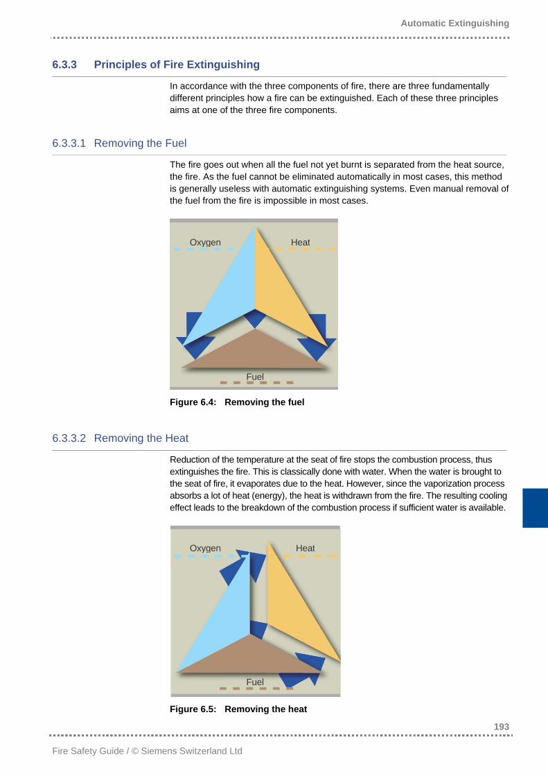
The fire goes out when all the fuel not yet burnt is separated from the heat source, the fire. As the fuel cannot be eliminated automatically in most cases, this method is generally useless with automatic extinguishing systems. Even manual removal of the fuel from the fire is impossible in most cases.
Figure 6.4: Removing the fuel
HeatOxygen
Fuel
6.3.3.2 Removing the Heat
Reduction of the temperature at the seat of fire stops the combustion process, thus extinguishes the fire. This is classically done with water. When the water is brought to the seat of fire, it evaporates due to the heat. However, since the vaporization process absorbs a lot of heat (energy), the heat is withdrawn from the fire. The resulting cooling effect leads to the breakdown of the combustion process if sufficient water is available.
Figure 6.5: Removing the heat
Oxygen Heat
Fuel
Automatic Extinguishing
194
Fire Safety Guide / © Siemens Switzerland Ltd
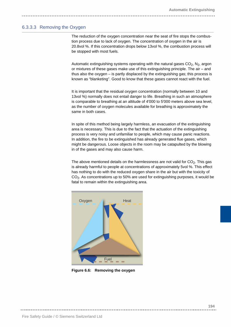
6.3.3.3 Removing the Oxygen
The reduction of the oxygen concentration near the seat of fire stops the combus-tion process due to lack of oxygen. The concentration of oxygen in the air is 20.8vol %. If this concentration drops below 13vol %, the combustion process will be stopped with most fuels. Automatic extinguishing systems operating with the natural gases CO2, N2, argon or mixtures of these gases make use of this extinguishing principle. The air – and thus also the oxygen – is partly displaced by the extinguishing gas; this process is known as “blanketing”. Good to know that these gases cannot react with the fuel. It is important that the residual oxygen concentration (normally between 10 and 13vol %) normally does not entail danger to life. Breathing in such an atmosphere is comparable to breathing at an altitude of 4'000 to 5'000 meters above sea level, as the number of oxygen molecules available for breathing is approximately the same in both cases. In spite of this method being largely harmless, an evacuation of the extinguishing area is necessary. This is due to the fact that the actuation of the extinguishing process is very noisy and unfamiliar to people, which may cause panic reactions. In addition, the fire to be extinguished has already generated flue gases, which might be dangerous. Loose objects in the room may be catapulted by the blowing in of the gases and may also cause harm. The above mentioned details on the harmlessness are not valid for CO2. This gas is already harmful to people at concentrations of approximately 5vol %. This effect has nothing to do with the reduced oxygen share in the air but with the toxicity of CO2. As concentrations up to 50% are used for extinguishing purposes, it would be fatal to remain within the extinguishing area.
Figure 6.6: Removing the oxygen
HeatOxygen
Fuel
Automatic Extinguishing
195
Fire Safety Guide / © Siemens Switzerland Ltd
Foam extinguishing is based on removing the oxygen as well. The foam forms a separation layer between the burning material and the oxygen in the air. Chemical extinguishing agents such as HFC227ea or Novec™ 1230 are usually applied in concentrations below 10vol %. They are long-chained molecules consist-ing of many atoms. When such an extinguishing agent molecule penetrates the reaction zone, it is decomposed in smaller parts, ideally in its atoms. This decom-position leads – in accordance with the gas law – to an expansion of the extin-guishing gas on the one hand and thus to a local reduction of the oxygen concentration. On the other hand, the decomposition of the molecule and the subsequent recombination also leads to heat absorption, which in turn lowers the temperature. Chemical extinguishing agents thus withdraw heat from the fire, simultaneously reducing the oxygen concentration, which is a combination of the two latter effects described. Which of the effects will dominate depends on the extinguishing agent applied.
6.3.4 Flooding Time and Holding Time
The flooding time is the time between the activation of the extinguishing process and the moment the required extinguishing concentration is reached. The holding time is the period of time during which the extinguishing system maintains the required concentration by continuous supply of extinguishing agent. In accordance with the exact conditions prevailing at the seat of fire, a successful extinguishing process must prevent re-ignition. This can only be ensured when the required flooding and holding times are adhered to. As the cooling takes longer when the fire seat is larger, the required holding time depends on the fire size. It is thus important to detect fires at a possibly early stage when they are still relatively small. A consistently high response velocity, inde-pendent of the cause of the fire, is thus very advantageous in fire detection and subsequent extinguishing. The quality of fire detection is a decisive factor, even when an automatic extinguishing system is installed.
Automatic Extinguishing
196
Fire Safety Guide / © Siemens Switzerland Ltd
6.4 Water Extinguishing Systems
Without doubt, water is by far the most important element on earth. Approximately 71% of the earth’s surface is covered by water. Fauna and flora consist by 60 to 90% of water, and the atmosphere contains an equally significant amount of water in the form of humidity. Water is a fundamental prerequisite for life. For this reason, in mythology, water has been a symbol of life for thousands of years. Water has played the main part in fire extinguishing since ancient times, and it is for sure the oldest and most common extinguishing agent. As approximately 90% of all fires are solid fuel fires (= class A) which can be easily extinguished with water, it is still the most widespread extinguishing agent today.
6.4.1 Water as an Extinguishing Agent
The extinguishing principle of water (H2O) has already been discussed in section 6.3.3. Its main effect is cooling. Water has a high specific heat capacity and an especially high evaporation heat: • To heat up 1 liter of water from 10 to 100°C, 375KJ or 90kcal are required. • To evaporate 1 liter of water from 100°C to water vapor, 2260KJ or 540kcal are
required. This cooling effect destroys the thermal base of the chain reaction. Moreover, unburnt combustible material is covered with water and hence separated from the oxygen. In addition, water constitutes a heat sink (= absorption of heat). These effects reduce both the rate of fire propagation and – after extinguishing – the risk of re-ignition. A side effect of extinguishing with water is the generation of water vapor (steam). On complete evaporation, 1 liter of water is converted into approximately 1,690 liters of water vapor, which may lead to further blanketing. This side effect is unim-portant with sprinkler systems, but it plays a role with water fog systems, which is described in detail in the sections 6.4.4 and 6.7.4. How the water is applied to the fire is crucial for its extinguishing capability. A great number of small droplets have a much better cooling effect than a concentrated water jet.
6.4.2 Sprinkler Systems
The first patent for a sprinkler system was issued in 1723 to a chemist named Ambrose Godfrey. This system consisted of a tank containing water and the water was distributed by a gun powder load which was in turn ignited by the fire to be extinguished.
Automatic Extinguishing
197
Fire Safety Guide / © Siemens Switzerland Ltd
The first installation using a pipe system was invented in 1806 by an Englishman named John Carey: A master valve was kept closed by a system of ropes and counterweights. When the ropes caught fire, the valve was opened due to the counterweights, and water was released from a water tank positioned at a higher level. The first systems with perforated sprinkler pipes were installed in the United States in 1852. Major A. Stewart Harrison from London invented the first automatic sprin-kler head which, however, was never used or patented. The first usable sprinkler head was patented in the United States in 1874 by Henry S. Parmelee. This sprinkler was already equipped with a fusible link the design of which has been revised many times until today. Around the same time, the so-called “wet sprinkler systems” were introduced. This design finally became estab-lished as it facilitated faster extinguishing. Dry-pipe systems made it possible to protect unheated buildings where a wet-pipe sprinkler system would freeze in winter. The first widely accepted valve for dry-pipe systems was patented by Frederick Grinnell in 1885. In 1924, the Grinnell quartz bulb was introduced, followed by the “Save all” sprinkler head in 1931, which was already activated by a melting, organic compound. The spray technique was largely neglected until the middle of the twentieth cen-tury. However, from 1947 to 1950, the Factory Mutual Laboratories conducted experimental studies on this topic, resulting in the development of a spray sprinkler head which became the standard for automatic sprinkler heads in 1955.
6.4.2.1 Protection Objectives of Sprinkler Systems
As already mentioned, sprinkler systems primarily serve the purpose of building protection. Although the protection of valuables or people in the building must by no means be neglected, it is basically a consequence of the first protection objec-tive. Sprinklers are automatically activated individually when the temperature measured on the sprinkler head exceeds a critical value. As the activation automatically triggers the water supply, sprinkler systems also serve as fire detection systems and are normally directly connected to the intervention forces on site or to the fire brigade.
Automatic Extinguishing
198
Fire Safety Guide / © Siemens Switzerland Ltd
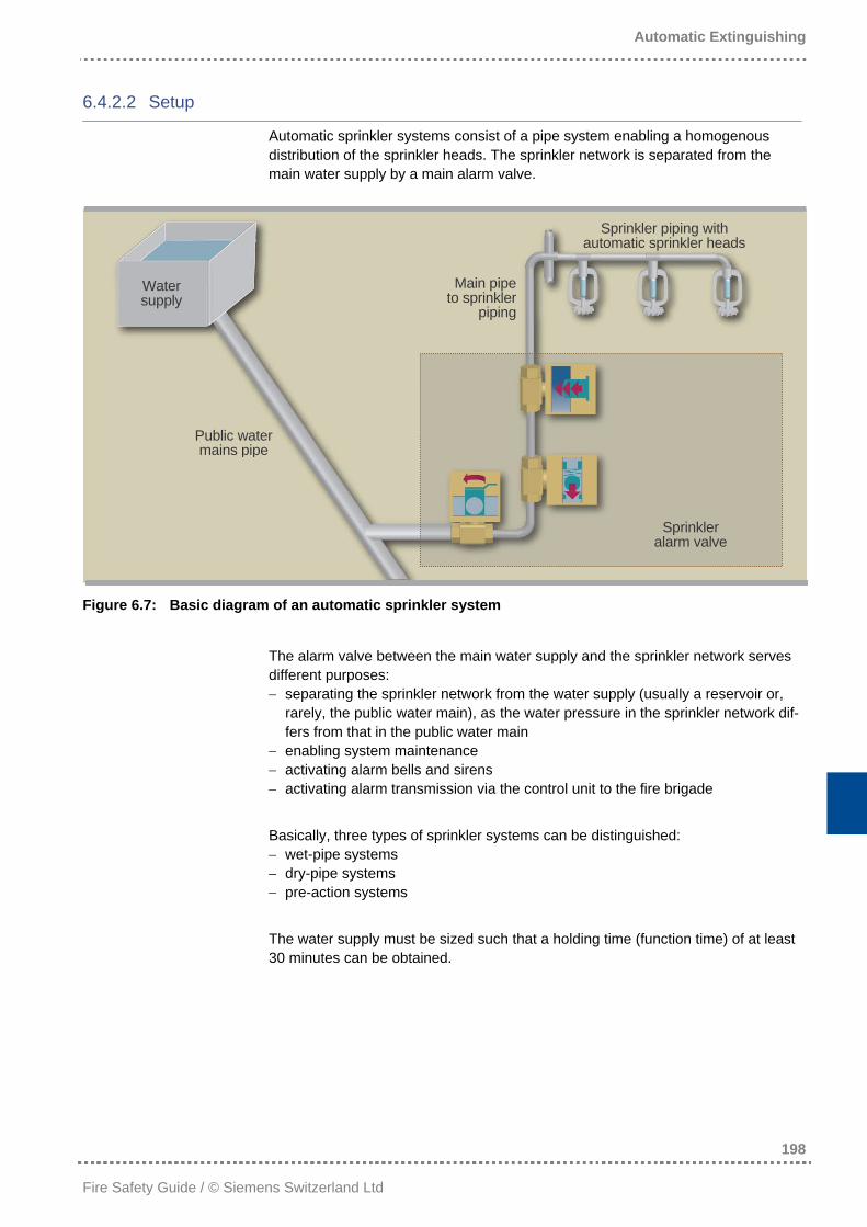
6.4.2.2 Setup
Automatic sprinkler systems consist of a pipe system enabling a homogenous distribution of the sprinkler heads. The sprinkler network is separated from the main water supply by a main alarm valve.
Sprinkler piping with automatic sprinkler heads
Main pipeto sprinkler
piping
Water supply
Sprinkler alarm valve
Public water mains pipe
Figure 6.7: Basic diagram of an automatic sprinkler system
The alarm valve between the main water supply and the sprinkler network serves different purposes: − separating the sprinkler network from the water supply (usually a reservoir or,
rarely, the public water main), as the water pressure in the sprinkler network dif-fers from that in the public water main
− enabling system maintenance − activating alarm bells and sirens − activating alarm transmission via the control unit to the fire brigade Basically, three types of sprinkler systems can be distinguished: − wet-pipe systems − dry-pipe systems − pre-action systems The water supply must be sized such that a holding time (function time) of at least 30 minutes can be obtained.
Automatic Extinguishing
199
Fire Safety Guide / © Siemens Switzerland Ltd
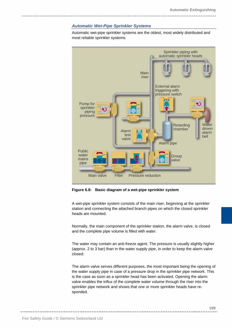
Automatic Wet-Pipe Sprinkler Systems Automatic wet-pipe sprinkler systems are the oldest, most widely distributed and most reliable sprinkler systems.
Sprinkler piping with automatic sprinkler heads
Mainriser
External alarm triggering with pressure switch
Pump forsprinkler
piping pressure
Water driven alarm bell
Retarding chamber Alarm
test valve
Alarm pipe
Public water mains pipe
Group valve
Main valve Filter Pressure reduction
Figure 6.8: Basic diagram of a wet-pipe sprinkler system
A wet-pipe sprinkler system consists of the main riser, beginning at the sprinkler station and connecting the attached branch pipes on which the closed sprinkler heads are mounted. Normally, the main component of the sprinkler station, the alarm valve, is closed and the complete pipe volume is filled with water. The water may contain an anti-freeze agent. The pressure is usually slightly higher (approx. 2 to 3 bar) than in the water supply pipe, in order to keep the alarm valve closed. The alarm valve serves different purposes, the most important being the opening of the water supply pipe in case of a pressure drop in the sprinkler pipe network. This is the case as soon as a sprinkler head has been activated. Opening the alarm valve enables the influx of the complete water volume through the riser into the sprinkler pipe network and shows that one or more sprinkler heads have re-sponded.
Automatic Extinguishing
200
Fire Safety Guide / © Siemens Switzerland Ltd
The same valve serves as a test valve and prevents contaminated water from flowing back from the sprinkler pipes to the water supply pipe.
Automatic Dry-Pipe Sprinkler Systems Dry-pipe sprinkler systems are a derivate of wet-pipe sprinkler systems to ensure protection of unheated rooms. Dry-pipe sprinkler systems require a pipe network similar to that of wet-pipe sprin-kler systems. This pipe network is under air overpressure instead of water pres-sure, with the air taking on the task of keeping the alarm valve closed. As dry-pipe sprinkler systems are particularly used for unheated buildings, the water-containing part, i.e. the alarm valve, must be heated. As the blowing-out of the air results in a delay compared with wet-pipe sprinkler systems, the fire has more time to develop. For this reason, neighboring sprinkler heads are usually activated simultaneously. In comparison with wet-pipe sprinkler systems, more sprinkler heads are activated, resulting in correspondingly higher water discharge.
Pre-Action Systems These systems are installed in rooms where the activation of sprinklers would entail considerable damage, for example in EDP rooms. For this reason any un-wanted activation, for example by mechanical damage, must be avoided at any rate. Like with dry-pipe systems, the pipe network is filled with pressurized air. The alarm valve station, however, is designed in such a way that it can only open when a fire detection system has additionally responded. This means that mechanical damage alone cannot lead to a water discharge.
6.4.2.3 Sprinkler Heads
Sprinklers have two functions: − selective fire detection − generation of water droplets in a predefined size and their distribution over the
coverage area All sprinklers are of the same design, consisting of the sprinkler head with nozzle, sealing element, activation element and spray plate. With the glass bulb sprinkler, the activation element is a glass bulb filled with a liquid. The water bulb bursts when it is heated up, due to the strongly rising pres-sure of the filling material. With the fusible element sprinkler, the activation element is made up of the soldering joint of two plates. The soldering metal used melts at a defined temperature.
Automatic Extinguishing
201
Fire Safety Guide / © Siemens Switzerland Ltd
With both sprinkler types, the sealing element is catapulted from the nozzle by the water or air pressure in the sprinkler pipe network. The water flowing out is divided up into droplets by the spray plate and sprayed over the coverage area. With standing sprinklers, the water flow must be additionally turned downwards.
Sprinkler Types The sprinkler types are determined by the nature of water distribution and their application area: − normal sprinklers − spray sprinklers − flat spray sprinklers − sidewall sprinklers − ESFR sprinklers − wide-range wall sprinklers Normal sprinklers direct more water to the ceiling than spray sprinklers. This effect was consciously used to cool the wooden construction, which was the most common building construction type in the past. Fire tests have revealed that even with spray sprinklers, the temperatures below the ceiling remain within limits that imply no risk of an ignition of the wooden construction. For this reason, spray sprinklers are most widely used in Germany, for example. Flat spray sprinklers are installed when there is not enough free space between the sprinkler and the equipment or stored goods. Sidewall sprinklers are used with limited ceiling heights and when there is risk of mechanical damage to the sprinklers. ESFR sprinklers (Early Suppression Fast Response) have been developed for use in risky storage facilities with high storage heights, without sprinklers on inter-mediate levels. In addition to a quicker activation element, they have a different water distribution spectrum with a very high water charge of more than 40 l/m2 per minute. Due to the large nozzle bore and the high minimum pressure, larger drops are ejected at higher speed, being more likely to penetrate the flames and directly extinguish the seat of fire. The installation of ESFR sprinklers requires full adher-ence to many building construction specifications, such as the inclination angle of the roof, and is therefore not always possible. Wide-range wall sprinklers have been developed for the use in small rooms of limited heights, to be mounted on one wall. Hotels and offices are typical applica-tion areas for this sprinkler type.
Automatic Extinguishing
202
Fire Safety Guide / © Siemens Switzerland Ltd
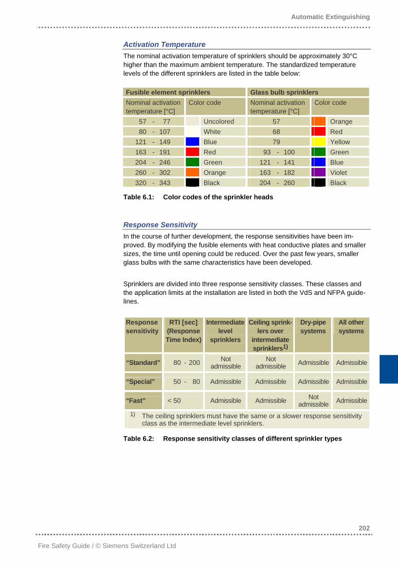
Activation Temperature The nominal activation temperature of sprinklers should be approximately 30°C higher than the maximum ambient temperature. The standardized temperature levels of the different sprinklers are listed in the table below: Fusible element sprinklers Glass bulb sprinklers Nominal activation temperature [°C]
Color code Nominal activation temperature [°C]
Color code
57 - 77 Uncolored 57 Orange 80 - 107 White 68 Red 121 - 149 Blue 79 Yellow 163 - 191 Red 93 - 100 Green 204 - 246 Green 121 - 141 Blue 260 - 302 Orange 163 - 182 Violet 320 - 343 Black 204 - 260 Black
Table 6.1: Color codes of the sprinkler heads
Response Sensitivity In the course of further development, the response sensitivities have been im-proved. By modifying the fusible elements with heat conductive plates and smaller sizes, the time until opening could be reduced. Over the past few years, smaller glass bulbs with the same characteristics have been developed. Sprinklers are divided into three response sensitivity classes. These classes and the application limits at the installation are listed in both the VdS and NFPA guide-lines. Response sensitivity
RTI [sec] (Response Time Index)
Intermediate level
sprinklers
Ceiling sprink-lers over
intermediate sprinklers1)
Dry-pipe systems
All other systems
“Standard” 80 - 200 Not admissible
Not admissible Admissible Admissible
“Special” 50 - 80 Admissible Admissible Admissible Admissible
“Fast” < 50 Admissible Admissible Not admissible Admissible
1) The ceiling sprinklers must have the same or a slower response sensitivity class as the intermediate level sprinklers.
Table 6.2: Response sensitivity classes of different sprinkler types
Automatic Extinguishing
203
Fire Safety Guide / © Siemens Switzerland Ltd
6.4.3 Water Spray Extinguishing Systems
Water spray (also called “deluge”) extinguishing systems are stationary water extinguishing systems. In terms of setup, they are similar to sprinkler systems. The two most significant differences to sprinkler systems are: • The system is provided with open sprinkler heads or nozzles; the water spray
heads have no heat-sensitive elements. • To activate the water spray range valves, a separate fire detection system is
required. What is most characteristic for water spray extinguishing systems is their large-area water spraying through many spray heads. The deluge system has been developed for areas with a particularly high combustible load, such as fuel storage facilities where a quick fire spread has to be expected. In such cases, neither wet nor dry extinguishing systems with their individually opening sprinkler heads could control the quickly spreading fire, especially because a limited number of sprinkler heads distribute the water only locally and too late. Due to the very high water volumes discharged in case of activation, water spray systems require an extremely high capacity of water supply. A deluge system consists of the following indispensable components: − reliable water supply − main valve − deluge system range valves − fire detection system with interface to the deluge system − pipe system − open deluge system heads The water supply must have a very high capacity and is therefore normally equipped with stationary extinguishing pumps, as the water supply usually does not generate a sufficiently high pressure which would in turn not generate a suffi-cient water flow for all simultaneously opened spray heads. The main valve re-quires a position indicator to switch off the deluge system and the deluge system range valves require an electric, hydraulic, or pneumatic drive and allow manual activation.
Automatic Extinguishing
204
Fire Safety Guide / © Siemens Switzerland Ltd
6.4.4 Water Fog Extinguishing Systems
Over the past few years, the water fog extinguishing technology has gained in importance both for room and object protection. Different products have been developed by various suppliers for a wide range of applications. All these solutions have one thing in common: In contrast to the conventional sprinkler technology, they try to achieve a droplet spectrum with the smallest possible diameters by applying higher pressures (up to 100bar) and specially designed nozzles, in order to achieve better cooling, or evaporation respectively, by the larger droplet surface. However, on the market and especially among customers, there is considerable uncertainty about extinguishing principles, flooding times or application limits. This is aggravated by the fact that there is no directive giving a definite answer to such questions. The planned European standard (CEN TC 191 WG 5) has not been published yet. In comparison to sprinkler systems, the water fog technology aims at applying considerably lower water volumes, as tests and approvals have shown. The Euro-pean standard on water fog systems, currently being developed by CEN, will consider these systems as a sprinkler system replacement. Every extinguishing system must successfully pass fire tests for each application, proving that it is at least as efficient as a sprinkler system. The flooding time of all water fog extin-guishing systems is up to 30 minutes according to this planned standard. The tank must thus be sized accordingly. Often, however, more advanced objectives are propagated for water fog systems, such as: • For room protection, water fog supposedly is able to “reach around corners”, i.e.
the nozzle jet need not necessarily be directed to the fire seat. • Instead of fire suppression, as it is the case with sprinklers, safe fire extinguish-
ing can supposedly be achieved as with gas extinguishing systems. It should thus also be possible to considerably reduce the flooding time.
These objectives, however, are not only contradictory to all previously published guideline drafts. They are also in contrast to physical laws. This is discussed in detail in section 6.7.4 “Water Fog Systems as a Replacement for Gas Extinguishing Systems?“ starting on page 222.
Automatic Extinguishing
205
Fire Safety Guide / © Siemens Switzerland Ltd
6.5 Foam Extinguishing Systems
Foam as an extinguishing agent was invented as early as 1880. At that time, the search for crude oil had virtually caused a sudden increase in the number of drilling derricks, frequently causing oil fires. As it is impossible to fight such fires with water, soap was added to the water, with the expected effect of reducing the water’s surface tension. These conditions were the origin of the use of extinguish-ing foams in fire protection: A mixture of water and foam-generating additives.
6.5.1 Foam as an Extinguishing Agent
Foam is usually generated in two steps: − mixture: water + foam-generating agent foam solution − generation: foam solution + compressed air foam Many different types of foams have been developed until today, all of which have the same effect on fire: By covering the burning surface, the fuel (solid or liquid) is separated from the ambient air and thus from oxygen. Added to this is a cooling effect dependent on the foam type.
6.5.2 Foam Types
The ideal foam for fire protection purposes must have the following characteristics: − it retains its water share as long as possible to build a vapor barrier layer over
the burning surface − it flows quickly and easily over a burning fuel surface − it protects from flashover until the burning material has cooled below the inflam-
mation temperature In addition, foam should have a number of other properties, for example it should be non-toxic, economic, easy to clean, adhere to vertical surfaces, etc. Unfortunately, in reality there is no foam having all these aforementioned charac-teristics. This is the reason for the large number of foam generators developed worldwide. This variety is divided into three classes: − low-expansion foam − medium-expansion foam − high-expansion foam These classes are distinguished on the basis of the air volume to be added.
Automatic Extinguishing
206
Fire Safety Guide / © Siemens Switzerland Ltd
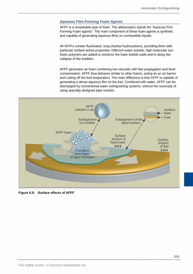
Aqueous Film-Forming Foam Agents AFFF is a remarkable type of foam. The abbreviation stands for “Aqueous Film Forming Foam agents”. The main component of these foam agents is synthetic and capable of generating aqueous films on combustible liquids. All AFFFs contain fluorinated, long-chained hydrocarbons, providing them with particular surface-active properties. Different water-soluble, high-molecular syn-thetic polymers are added to reinforce the foam bubble walls and to delay the collapse of the bubbles. AFFF generates air foam combining low viscosity with fast propagation and level compensation. AFFF thus behaves similar to other foams, acting as an air barrier and cutting off the fuel evaporation. The main difference is that AFFF is capable of generating a dense aqueous film on the fuel. Combined with water, AFFF can be discharged by conventional water extinguishing systems, without the necessity of using specially designed pipe nozzles.
AFFF solution in air
Enlargement of a bubble
Surface layerFuel Enlargement of the
liquid surface
AFFF foam
Transition from foam
to layer formation
Surfacetension of
liquid layerSurfacetension
of fuel
Figure 6.9: Surface effects of AFFF
Automatic Extinguishing
207
Fire Safety Guide / © Siemens Switzerland Ltd
6.5.3 System Setup and Function
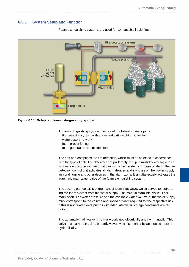
Foam extinguishing systems are used for combustible liquid fires.
Fire detection system
Nozzle piping
Foamagent
container
Alarm valve
Proportioner
Figure 6.10: Setup of a foam extinguishing system
A foam extinguishing system consists of the following major parts: − fire detection system with alarm and extinguishing activation − water supply network − foam proportioning − foam generation and distribution The first part comprises the fire detection, which must be selected in accordance with the type of risk. The detectors are preferably set up in multidetector logic, as it is common practice with automatic extinguishing systems. In case of alarm, the fire detection control unit activates all alarm devices and switches off the power supply, air conditioning and other devices in the alarm zone. It simultaneously activates the automatic main water valve of the foam extinguishing system. The second part consists of the manual foam inlet valve, which serves for separat-ing the foam system from the water supply. The manual foam inlet valve is nor-mally open. The water pressure and the available water volume of the water supply must correspond to the volume and speed of foam required for the respective risk. If this is not guaranteed, pumps with adequate water storage containers are re-quired. The automatic main valve is normally activated electrically and / or manually. This valve is usually a so-called butterfly valve, which is opened by an electric motor or hydraulically.
Automatic Extinguishing
208
Fire Safety Guide / © Siemens Switzerland Ltd
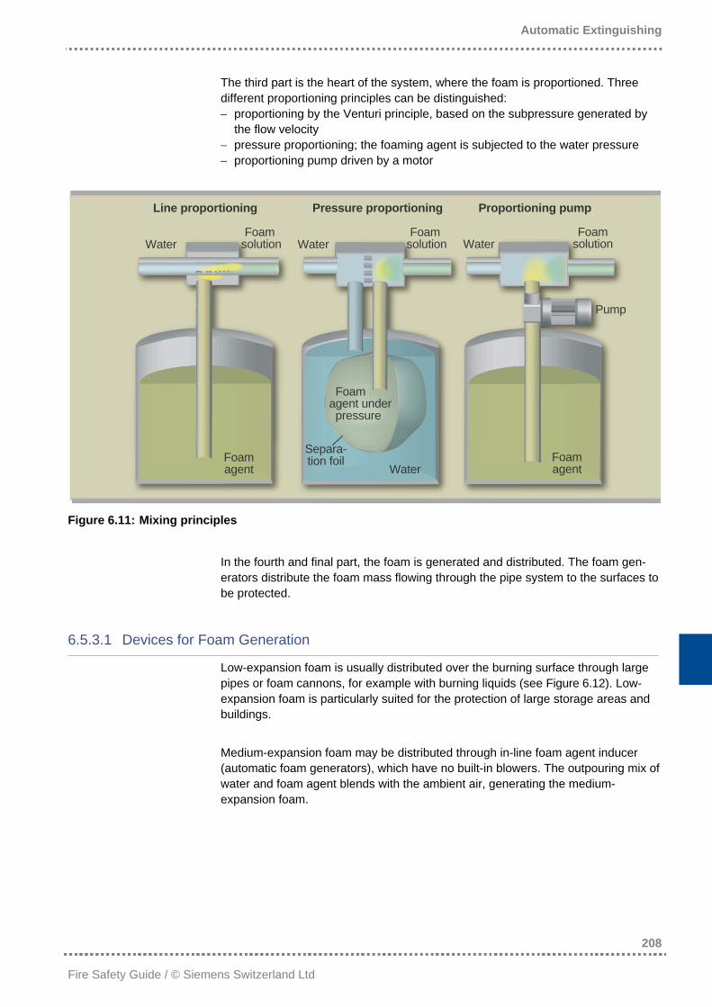
The third part is the heart of the system, where the foam is proportioned. Three different proportioning principles can be distinguished: − proportioning by the Venturi principle, based on the subpressure generated by
the flow velocity − pressure proportioning; the foaming agent is subjected to the water pressure − proportioning pump driven by a motor
Line proportioning Pressure proportioning Proportioning pump
Foam solution
Foam solution
Foam solution Water Water Water
Pump
Foam agent under pressure
Separa-tion foil Foam
agent
Water Foam agent
Figure 6.11: Mixing principles
In the fourth and final part, the foam is generated and distributed. The foam gen-erators distribute the foam mass flowing through the pipe system to the surfaces to be protected.
6.5.3.1 Devices for Foam Generation
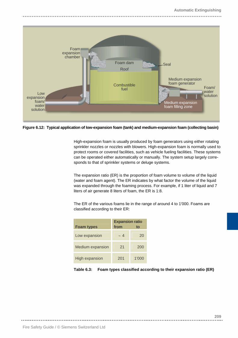
Low-expansion foam is usually distributed over the burning surface through large pipes or foam cannons, for example with burning liquids (see Figure 6.12). Low-expansion foam is particularly suited for the protection of large storage areas and buildings. Medium-expansion foam may be distributed through in-line foam agent inducer (automatic foam generators), which have no built-in blowers. The outpouring mix of water and foam agent blends with the ambient air, generating the medium-expansion foam.
Automatic Extinguishing
209
Fire Safety Guide / © Siemens Switzerland Ltd
Foamexpansion
chamberFoam dam
Roof Seal
Medium expansion foam generator Combustible
fuel Foam/ water solution Low
expansion foam/ water
solution
Medium expansion foam filling zone
Figure 6.12: Typical application of low-expansion foam (tank) and medium-expansion foam (collecting basin)
High-expansion foam is usually produced by foam generators using either rotating sprinkler nozzles or nozzles with blowers. High-expansion foam is normally used to protect rooms or covered facilities, such as vehicle fueling facilities. These systems can be operated either automatically or manually. The system setup largely corre-sponds to that of sprinkler systems or deluge systems. The expansion ratio (ER) is the proportion of foam volume to volume of the liquid (water and foam agent). The ER indicates by what factor the volume of the liquid was expanded through the foaming process. For example, if 1 liter of liquid and 7 liters of air generate 8 liters of foam, the ER is 1:8. The ER of the various foams lie in the range of around 4 to 1'000. Foams are classified according to their ER: Foam types
Expansion ratio from to
Low expansion ∼ 4 20
Medium expansion 21 200
High expansion 201 1'000
Table 6.3: Foam types classified according to their expansion ratio (ER)
Automatic Extinguishing
210
Fire Safety Guide / © Siemens Switzerland Ltd
6.6 Powder Extinguishing Systems
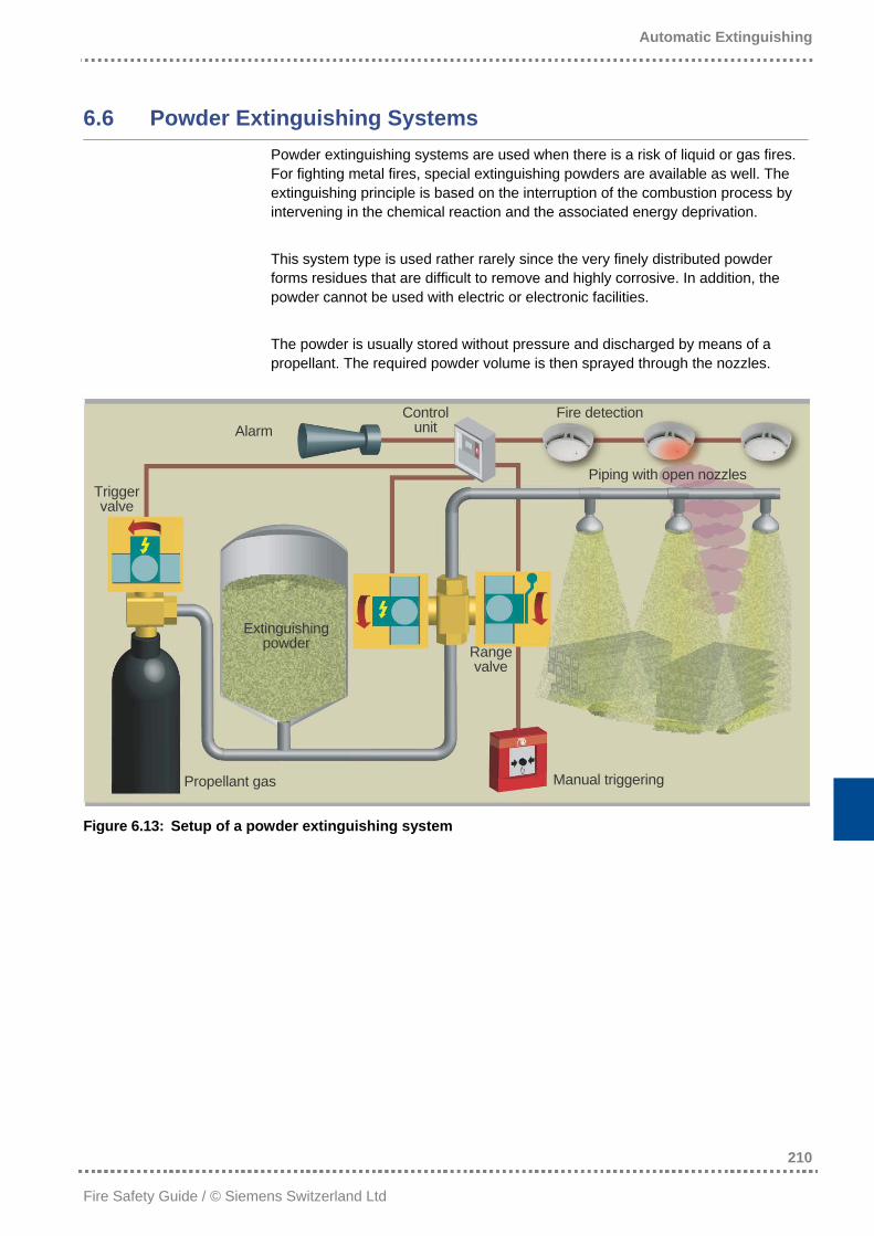
Powder extinguishing systems are used when there is a risk of liquid or gas fires. For fighting metal fires, special extinguishing powders are available as well. The extinguishing principle is based on the interruption of the combustion process by intervening in the chemical reaction and the associated energy deprivation. This system type is used rather rarely since the very finely distributed powder forms residues that are difficult to remove and highly corrosive. In addition, the powder cannot be used with electric or electronic facilities. The powder is usually stored without pressure and discharged by means of a propellant. The required powder volume is then sprayed through the nozzles.
Control unit
Fire detection Alarm
Piping with open nozzles Trigger valve
Extinguishing powder Range
valve
Manual triggering Propellant gas
Figure 6.13: Setup of a powder extinguishing system
Automatic Extinguishing
211
Fire Safety Guide / © Siemens Switzerland Ltd
6.7 Gas Extinguishing Systems
Currently, blanketing natural gases and chemically acting extinguishing gases are available as gaseous extinguishing agents. These gases are discussed in detail in the following sections.
6.7.1 Natural Gases
Natural gases are distinguished by two characteristics: − they can be found in nature − the extinguishing effect is achieved by oxygen displacement throughout the
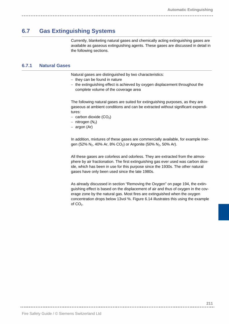
complete volume of the coverage area The following natural gases are suited for extinguishing purposes, as they are gaseous at ambient conditions and can be extracted without significant expendi-tures: − carbon dioxide (CO2) − nitrogen (N2) − argon (Ar) In addition, mixtures of these gases are commercially available, for example Iner-gen (52% N2, 40% Ar, 8% CO2) or Argonite (50% N2, 50% Ar). All these gases are colorless and odorless. They are extracted from the atmos-phere by air fractionation. The first extinguishing gas ever used was carbon diox-ide, which has been in use for this purpose since the 1930s. The other natural gases have only been used since the late 1980s. As already discussed in section “Removing the Oxygen” on page 194, the extin-guishing effect is based on the displacement of air and thus of oxygen in the cov-erage zone by the natural gas. Most fires are extinguished when the oxygen concentration drops below 13vol %. Figure 6.14 illustrates this using the example of CO2.
Automatic Extinguishing
212
Fire Safety Guide / © Siemens Switzerland Ltd
Figure 6.14: Air composition in the protected area after CO2 flooding
The residual oxygen concentration aimed at in systems today is usually between 10vol % and 13vol %, corresponding to an extinguishing gas concentration be-tween 36vol % and 52vol %. A displacement of such high gas volumes always requires overpressure release in the coverage area. The residual oxygen concentration should not fall below 10vol %, since below this level adverse health effects on people remaining in the protection zone cannot be ruled out. The LOAEL value (lower observed adverse effect level) is then ex-ceeded. In some countries, like for instance Germany, the installation of a special time delay unit is required in this case, providing for additional safety in adhering to the evacuation period. As carbon dioxide is always toxic, increased requirements on the protection of people are essential with this gas. A certain evacuation time, depending on the size of the protection zone, must always be taken into account. The extinguishing agent concentration to be actually used depends on the type of fuel. To extinguish a methanol fire, for example, considerably more gas is required than for wood. The concentrations are determined in experiments, either in stan-dardized room tests or in standardized tests of reduced scale (cup burner test). A safety margin (generally 30%) is then added to these theoretical concentrations, resulting in the application concentration. The methods for determining the concentration as well as the effectively required concentrations for each risk can be taken from the following guidelines: VdS 2093 and NFPA 12 for CO2, and VdS 2380, ISO 14520 or NFPA 2001 for all other gases.
Nitrogen 79% Nitrogen 39.5%
Carbon dioxide (CO2) 50%
Oxygen 21% Oxygen 10.5%
Composition of ambient air
Air composition after CO2 discharge

Automatic Extinguishing
213
Fire Safety Guide / © Siemens Switzerland Ltd
Studying these guidelines, it becomes obvious that the different types of natural gases require different concentrations, even when the protection objective and risk remain the same. This seems surprising at first, as it is not to be expected if oxygen dis-placement is the only extinguishing effect. However, in addition to oxygen displace-ment, the heat absorption by the extinguishing gas plays a role, although a rather subordinate one. The only independent comparative study in which all gases have been compared in the same test setup has been conducted by the VdS in Germany (Report CEA GEI 7 – N 125). This study revealed that carbon dioxide has the best extinguishing properties, followed by nitrogen, while argon performs worst. This is hardly surprising, as carbon dioxide molecules consist of three atoms, nitrogen consists of two, and argon molecules of only one. The more atoms a molecule has, the more bonds there are which may absorb energy. The efficiencies of gas mixtures range between nitrogen and argon. There is thus no reason to revert to these gases. For this reason, the use of pure natural gases is advantageous: For reasons of danger to life, carbon dioxide is only used for object protection and for rooms that are not frequented by people (e.g. generator rooms). Nitrogen is used for standard applications such as EDP rooms whereas argon is applied for special cases such as metal fires, where metals like magnesium would react with nitrogen. The different weights, or the different densities of the gases respectively, play no role in room protection, as the gases do not decompose after flooding in a gas-tight room. This has been shown in experiments, but the atmosphere also shows that there is no gas decomposition. A gas-tight room is an ultimate prerequisite for the proper functioning of gas extinguishing systems, as the concentration must be retained during a holding time of at least 10 minutes in order to prevent re-ignition. In object protection, however – meaning the protection of open equipment – the gas weight is crucial. Carbon dioxide is the only suitable gas here, as it is heavier than air and can thus be retained close to the object. Natural gases can be used for the following fuels or materials: − combustible gases, provided that no ignitable mixture can be generated after
extinguishing − combustible liquids or matters reacting like combustible liquids in case of fire − solid matters possibly requiring a higher concentration and longer holding time − electric and electronic equipment
6.7.2 Chemical Extinguishing Gases
Halon 1211 (CF2ClBr) and Halon 1301 (CF3Br) were the first chemical extinguish-ing gases used worldwide. In the stratosphere, however, these gases lead to the decomposition of ozone. In the scope of the efforts taken to protect the ozone layer, their replacement was decided in the Montreal Protocol of 1987 and conse-quential international agreements. With the exception of strategic special applica-tions (aviation, military, nuclear energy technology), the use of halogenated hydrocarbons is prohibited for the purpose of fire protection. Refilling of existing halogenated hydrocarbons extinguishing systems is equally illegal in most coun-tries. In the European Union, halogenated hydrocarbons extinguishing systems had to be withdrawn by December 31, 2003. In Germany, this decommissioning was already completed by January 1, 1994.
Automatic Extinguishing
214
Fire Safety Guide / © Siemens Switzerland Ltd
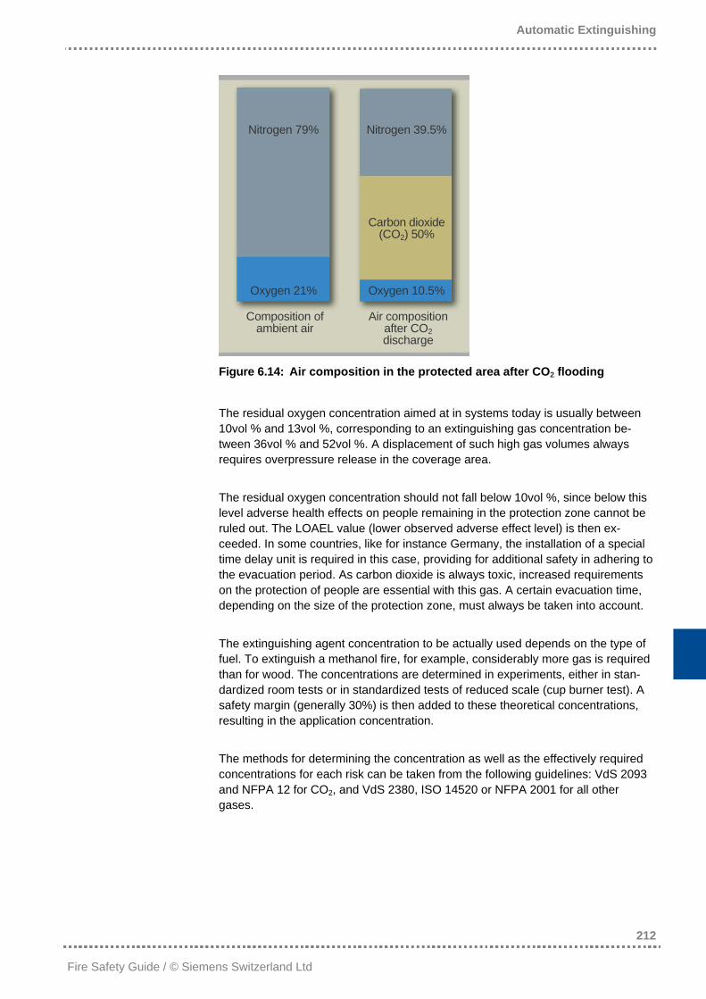
To replace the halons, halogenated carbohydrates were introduced on the market in the mid-1990s. These substances have no ozone-depleting effect and have an ODP value (ozone depletion potential) of 0. Especially the two groups of fluorinated carbohydrates and perfluorinated carbohydrates must be mentioned here. Well-known extinguishing gases from the group of fluorinated carbohydrates (HFCs) are HFC227ea (C3F7H, which is marketed by Great Lakes under the name of FM 200™) and HFC125 (C2F5H), for example. This group has found wider distribution than that of the perfluorinated carbohydrates (PFCs). From the group of halo-genated carbohydrates, only HFC227ea and Trigon are today approved as extin-guishing agents in Germany. These gases, however, strongly contribute to the greenhouse effect. They all have a GWP value (global warming potential) of more than 2'000, meaning that their contribution to the greenhouse effect is more than 2'000 times that of carbon dioxide. The actions regarding the protection against global warming, agreed upon in the Kyoto Protocol, decisively limit the use of halogenated carbohydrates. Although an international ban or restriction of their use in fire protection is not foreseeable at present, some countries such as Austria have issued more restrictive conditions for their use. In Switzerland, the use of HFCs is forbidden. In 2003, 3M™ launched a new chemical extinguishing gas under the trade name 3M™ Novec™ 1230 Fire Protection Fluid. This gas belongs to none of the afore-mentioned groups; it is a fluorinated ketone with the chemical formula CF3CF2C(O)CF(CF3) 2, which has already given proof of its extinguishing efficiency for room protection purposes in different extinguishing tests. In a corresponding draft of the ISO 14520 guideline, it is listed under the name of FK-5-1-12. It not only has an ODP value of 0 but also a GWP value of 1, meaning that its contribu-tion to the greenhouse effect is not stronger than that of CO2. This property makes it possible to categorize chemical extinguishing gases in the following generations: 1st generation 2nd generation 3rd generation
Environment parameters
ODP > 0 GWP >> 0
ODP = 0 GWP >> 0
ODP = 0 GWP ≈ 1
Gases (selection)
Halon 1211 Halon 1301 NAF S III
HFC227ea HFC125 HFC23 CEA410
FK-5-1-12 (Novec™ 1230)
Table 6.4: Generations of chemical extinguishing gases
Automatic Extinguishing
215
Fire Safety Guide / © Siemens Switzerland Ltd
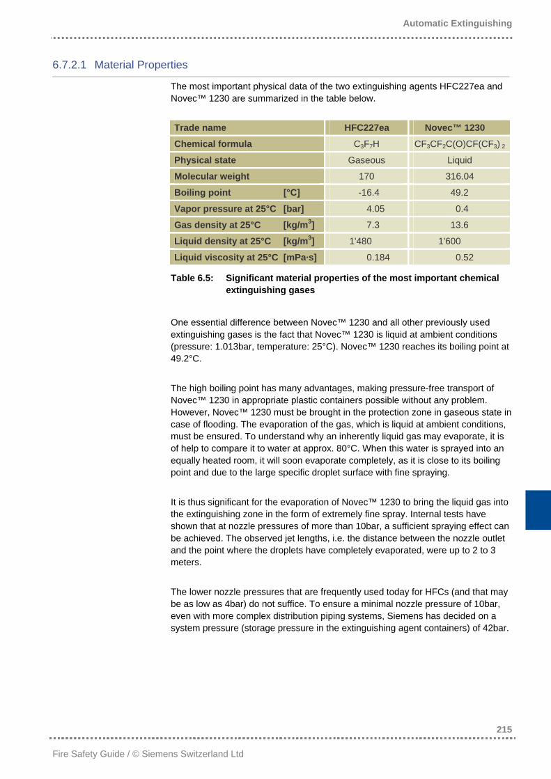
6.7.2.1 Material Properties
The most important physical data of the two extinguishing agents HFC227ea and Novec™ 1230 are summarized in the table below. Trade name HFC227ea Novec™ 1230
Chemical formula C3F7H CF3CF2C(O)CF(CF3) 2
Physical state Gaseous Liquid
Molecular weight 170 316.04
Boiling point [°C] -16.4 49.2
Vapor pressure at 25°C [bar] 4.05 0.4
Gas density at 25°C [kg/m3] 7.3 13.6
Liquid density at 25°C [kg/m3] 1'480 1'600
Liquid viscosity at 25°C [mPa·s] 0.184 0.52
Table 6.5: Significant material properties of the most important chemical extinguishing gases
One essential difference between Novec™ 1230 and all other previously used extinguishing gases is the fact that Novec™ 1230 is liquid at ambient conditions (pressure: 1.013bar, temperature: 25°C). Novec™ 1230 reaches its boiling point at 49.2°C. The high boiling point has many advantages, making pressure-free transport of Novec™ 1230 in appropriate plastic containers possible without any problem. However, Novec™ 1230 must be brought in the protection zone in gaseous state in case of flooding. The evaporation of the gas, which is liquid at ambient conditions, must be ensured. To understand why an inherently liquid gas may evaporate, it is of help to compare it to water at approx. 80°C. When this water is sprayed into an equally heated room, it will soon evaporate completely, as it is close to its boiling point and due to the large specific droplet surface with fine spraying. It is thus significant for the evaporation of Novec™ 1230 to bring the liquid gas into the extinguishing zone in the form of extremely fine spray. Internal tests have shown that at nozzle pressures of more than 10bar, a sufficient spraying effect can be achieved. The observed jet lengths, i.e. the distance between the nozzle outlet and the point where the droplets have completely evaporated, were up to 2 to 3 meters. The lower nozzle pressures that are frequently used today for HFCs (and that may be as low as 4bar) do not suffice. To ensure a minimal nozzle pressure of 10bar, even with more complex distribution piping systems, Siemens has decided on a system pressure (storage pressure in the extinguishing agent containers) of 42bar.
Automatic Extinguishing
216
Fire Safety Guide / © Siemens Switzerland Ltd
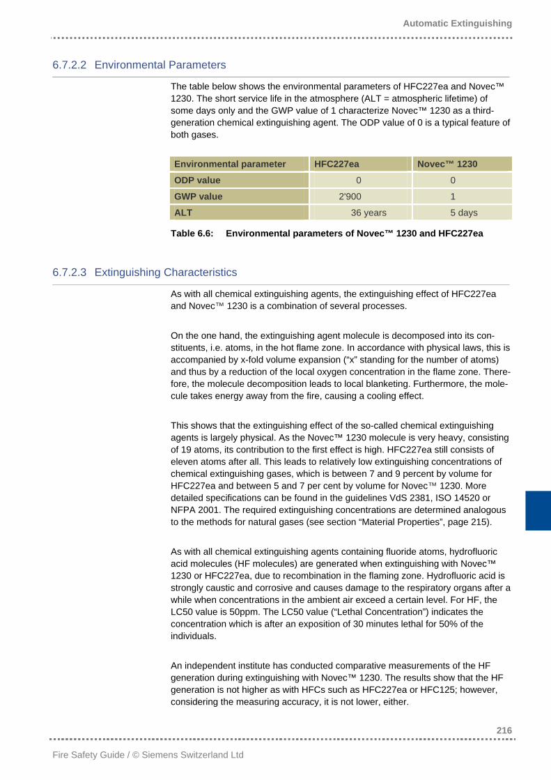
6.7.2.2 Environmental Parameters
The table below shows the environmental parameters of HFC227ea and Novec™ 1230. The short service life in the atmosphere (ALT = atmospheric lifetime) of some days only and the GWP value of 1 characterize Novec™ 1230 as a third-generation chemical extinguishing agent. The ODP value of 0 is a typical feature of both gases. Environmental parameter HFC227ea Novec™ 1230
ODP value 0 0
GWP value 2'900 1
ALT 36 years 5 days
Table 6.6: Environmental parameters of Novec™ 1230 and HFC227ea
6.7.2.3 Extinguishing Characteristics
As with all chemical extinguishing agents, the extinguishing effect of HFC227ea and Novec™ 1230 is a combination of several processes. On the one hand, the extinguishing agent molecule is decomposed into its con-stituents, i.e. atoms, in the hot flame zone. In accordance with physical laws, this is accompanied by x-fold volume expansion (“x” standing for the number of atoms) and thus by a reduction of the local oxygen concentration in the flame zone. There-fore, the molecule decomposition leads to local blanketing. Furthermore, the mole-cule takes energy away from the fire, causing a cooling effect. This shows that the extinguishing effect of the so-called chemical extinguishing agents is largely physical. As the Novec™ 1230 molecule is very heavy, consisting of 19 atoms, its contribution to the first effect is high. HFC227ea still consists of eleven atoms after all. This leads to relatively low extinguishing concentrations of chemical extinguishing gases, which is between 7 and 9 percent by volume for HFC227ea and between 5 and 7 per cent by volume for Novec™ 1230. More detailed specifications can be found in the guidelines VdS 2381, ISO 14520 or NFPA 2001. The required extinguishing concentrations are determined analogous to the methods for natural gases (see section “Material Properties”, page 215). As with all chemical extinguishing agents containing fluoride atoms, hydrofluoric acid molecules (HF molecules) are generated when extinguishing with Novec™ 1230 or HFC227ea, due to recombination in the flaming zone. Hydrofluoric acid is strongly caustic and corrosive and causes damage to the respiratory organs after a while when concentrations in the ambient air exceed a certain level. For HF, the LC50 value is 50ppm. The LC50 value (“Lethal Concentration”) indicates the concentration which is after an exposition of 30 minutes lethal for 50% of the individuals. An independent institute has conducted comparative measurements of the HF generation during extinguishing with Novec™ 1230. The results show that the HF generation is not higher as with HFCs such as HFC227ea or HFC125; however, considering the measuring accuracy, it is not lower, either.
Automatic Extinguishing
217
Fire Safety Guide / © Siemens Switzerland Ltd
The use of chemical extinguishing agents in protected sectors frequented by people should at any rate be reduced to such risks where large flames are to be expected at the beginning of the flooding procedure. A fast-reacting fire detection system immune to deception is indispensable to keep the HF generation as low as possible. Furthermore, it is generally recommended to contain the risk of rapidly growing fires, such as liquid fires, with natural gases instead of chemical extin-guishing agents. In contrast, electronic risks can be met extremely well with chemi-cal extinguishing agents, as such fires grow slowly. Some examples are: − EDP rooms − telecommunication systems − control rooms − distributor rooms − false floors containing cabling The prescribed flooding time of 10 seconds (in comparison to 60 to 120 seconds with natural gases) makes possible the required quick extinguishing.
6.7.2.4 Toxicity
The NOAEL (No Observed Adverse Effect Level) value of both HFC227ea and Novec™ 1230 is above the application concentration, which means that the extin-guishing agent does not constitute any risk to people in the coverage area. How-ever, the coverage area should always be evacuated prior to flooding.
6.7.3 System technology
The gases are stored in pressure tanks: • The non-liquefiable inert gases Ar, N2 and gas mixtures in gas cylinders at
pressures of 200 to 300bar. • CO2, liquefying under pressure, in high-pressure systems in gas cylinders at
56bar or, with low-pressure systems, in large cooled containers. • Chemical gases are stored in gas cylinders, pressurized with nitrogen, acting as
propellant. The storage pressure is either 25 or 42bar. Extinguishing is controlled either manually or, preferably, automatically by means of a fire detection system. Only a quick, faultless actuation prevents consequential damage, as a fire shall be extinguished during its formation phase. When the system is actuated, the cylinder valves of high-pressure systems, or the container valves of low-pressure systems respectively, are opened. Alarm is trig-gered to warn people in the protected area, and flooding is released after a prede-fined delay period, so that the room can be evacuated. Doors and other openings are closed automatically. Further operating equipment, such as ventilation systems and fire dampers are activated. The overpressure relief mechanisms are only opened in case of overpressure in the coverage area, otherwise they remain closed.
Automatic Extinguishing
218
Fire Safety Guide / © Siemens Switzerland Ltd
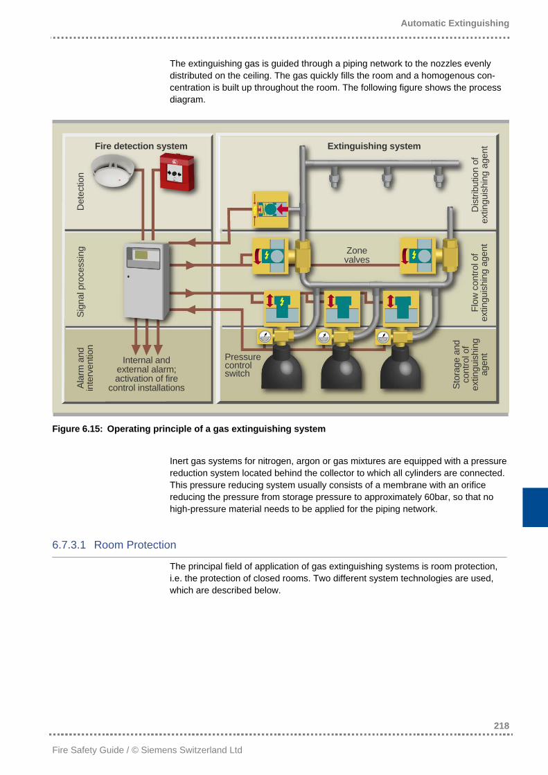
The extinguishing gas is guided through a piping network to the nozzles evenly distributed on the ceiling. The gas quickly fills the room and a homogenous con-centration is built up throughout the room. The following figure shows the process diagram.
Fire detection system Extinguishing system
Dis
tribu
tion
of
extin
guis
hing
age
nt
Det
ectio
n
Flow
con
trol o
f ex
tingu
ishi
ng a
gent
Sign
al p
roce
ssin
g Zone valves
Stor
age
and
cont
rol o
f ex
tingu
ishi
ng
agen
t
Alar
m a
nd
inte
rven
tion
Pressure control switch
Internal and external alarm; activation of fire
control installations
Figure 6.15: Operating principle of a gas extinguishing system
Inert gas systems for nitrogen, argon or gas mixtures are equipped with a pressure reduction system located behind the collector to which all cylinders are connected. This pressure reducing system usually consists of a membrane with an orifice reducing the pressure from storage pressure to approximately 60bar, so that no high-pressure material needs to be applied for the piping network.
6.7.3.1 Room Protection
The principal field of application of gas extinguishing systems is room protection, i.e. the protection of closed rooms. Two different system technologies are used, which are described below.
Automatic Extinguishing
219
Fire Safety Guide / © Siemens Switzerland Ltd
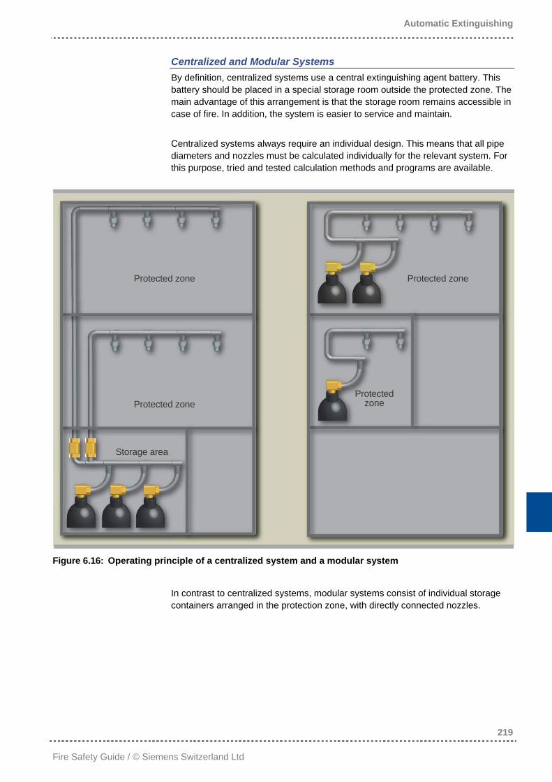
Centralized and Modular Systems By definition, centralized systems use a central extinguishing agent battery. This battery should be placed in a special storage room outside the protected zone. The main advantage of this arrangement is that the storage room remains accessible in case of fire. In addition, the system is easier to service and maintain. Centralized systems always require an individual design. This means that all pipe diameters and nozzles must be calculated individually for the relevant system. For this purpose, tried and tested calculation methods and programs are available.
Protected zone Protected zone
Protected zone Protected zone
Storage area
Figure 6.16: Operating principle of a centralized system and a modular system
In contrast to centralized systems, modular systems consist of individual storage containers arranged in the protection zone, with directly connected nozzles.
Automatic Extinguishing
220
Fire Safety Guide / © Siemens Switzerland Ltd
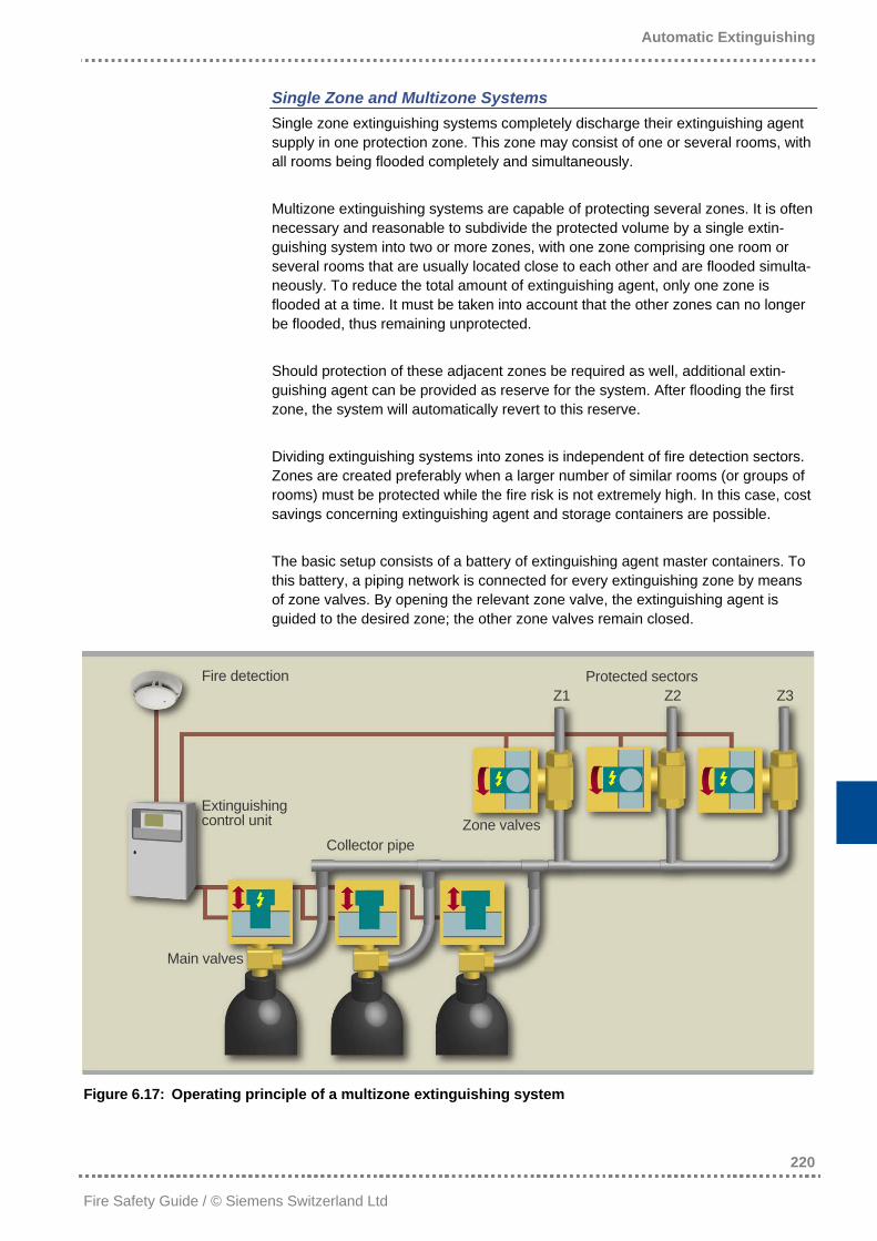
Single Zone and Multizone Systems Single zone extinguishing systems completely discharge their extinguishing agent supply in one protection zone. This zone may consist of one or several rooms, with all rooms being flooded completely and simultaneously. Multizone extinguishing systems are capable of protecting several zones. It is often necessary and reasonable to subdivide the protected volume by a single extin-guishing system into two or more zones, with one zone comprising one room or several rooms that are usually located close to each other and are flooded simulta-neously. To reduce the total amount of extinguishing agent, only one zone is flooded at a time. It must be taken into account that the other zones can no longer be flooded, thus remaining unprotected. Should protection of these adjacent zones be required as well, additional extin-guishing agent can be provided as reserve for the system. After flooding the first zone, the system will automatically revert to this reserve. Dividing extinguishing systems into zones is independent of fire detection sectors. Zones are created preferably when a larger number of similar rooms (or groups of rooms) must be protected while the fire risk is not extremely high. In this case, cost savings concerning extinguishing agent and storage containers are possible. The basic setup consists of a battery of extinguishing agent master containers. To this battery, a piping network is connected for every extinguishing zone by means of zone valves. By opening the relevant zone valve, the extinguishing agent is guided to the desired zone; the other zone valves remain closed.
Fire detection Protected sectors Z1 Z2 Z3
Extinguishing control unit Zone valves
Collector pipe
Main valves
Figure 6.17: Operating principle of a multizone extinguishing system
Automatic Extinguishing
221
Fire Safety Guide / © Siemens Switzerland Ltd
The right zone valve can be opened either simultaneously with the cylinder valves or beforehand, but it has proven to be of advantage to open it prior to the cylinder valves. When the zone valve is opened first, it is not yet under pressure as the cylinder valves are still closed. This decreases the risk of malfunction, as it is easier to open a valve without pressure, and the complete procedure is more fail-safe. The extinguishing control unit must be capable of subsequently and automatically actuating both the zone valve and the cylinder valve.
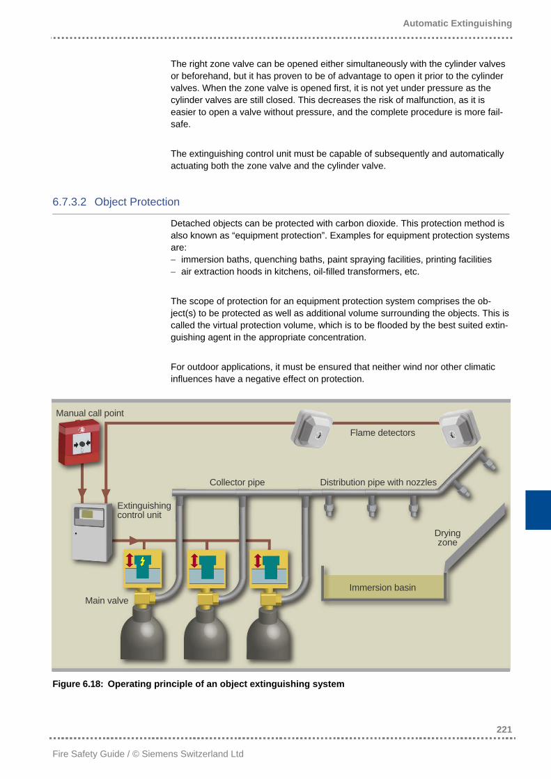
6.7.3.2 Object Protection
Detached objects can be protected with carbon dioxide. This protection method is also known as “equipment protection”. Examples for equipment protection systems are: − immersion baths, quenching baths, paint spraying facilities, printing facilities − air extraction hoods in kitchens, oil-filled transformers, etc. The scope of protection for an equipment protection system comprises the ob-ject(s) to be protected as well as additional volume surrounding the objects. This is called the virtual protection volume, which is to be flooded by the best suited extin-guishing agent in the appropriate concentration. For outdoor applications, it must be ensured that neither wind nor other climatic influences have a negative effect on protection.
Manual call point
Flame detectors
Collector pipe Distribution pipe with nozzles
Extinguishing control unit
Drying zone
Immersion basin Main valve
Figure 6.18: Operating principle of an object extinguishing system
Automatic Extinguishing
222
Fire Safety Guide / © Siemens Switzerland Ltd
6.7.4 Water Fog Systems as a Replacement for Gas Extinguishing Systems?
As mentioned in section 6.4.4, some market participants would like to replace sprinkler systems and also gas extinguishing systems used in room and object protection with water fog systems. This would mean, however, that the following goals would have to be fulfilled: • For the purpose of room protection, water fog would have to be able to extin-
guish “around corners“. This means that the seat of fire would have to be extin-guished successfully even when it is not directly located in the range of the nozzle jet.
• Safe fire extinguishing must be guaranteed at any rate. This is the case with gas extinguishing systems (in contrast to the mere fire suppression effect of sprin-klers). Hence, the flooding time must be significantly reduced in comparison to sprinkler systems.
6.7.4.1 Room Protection
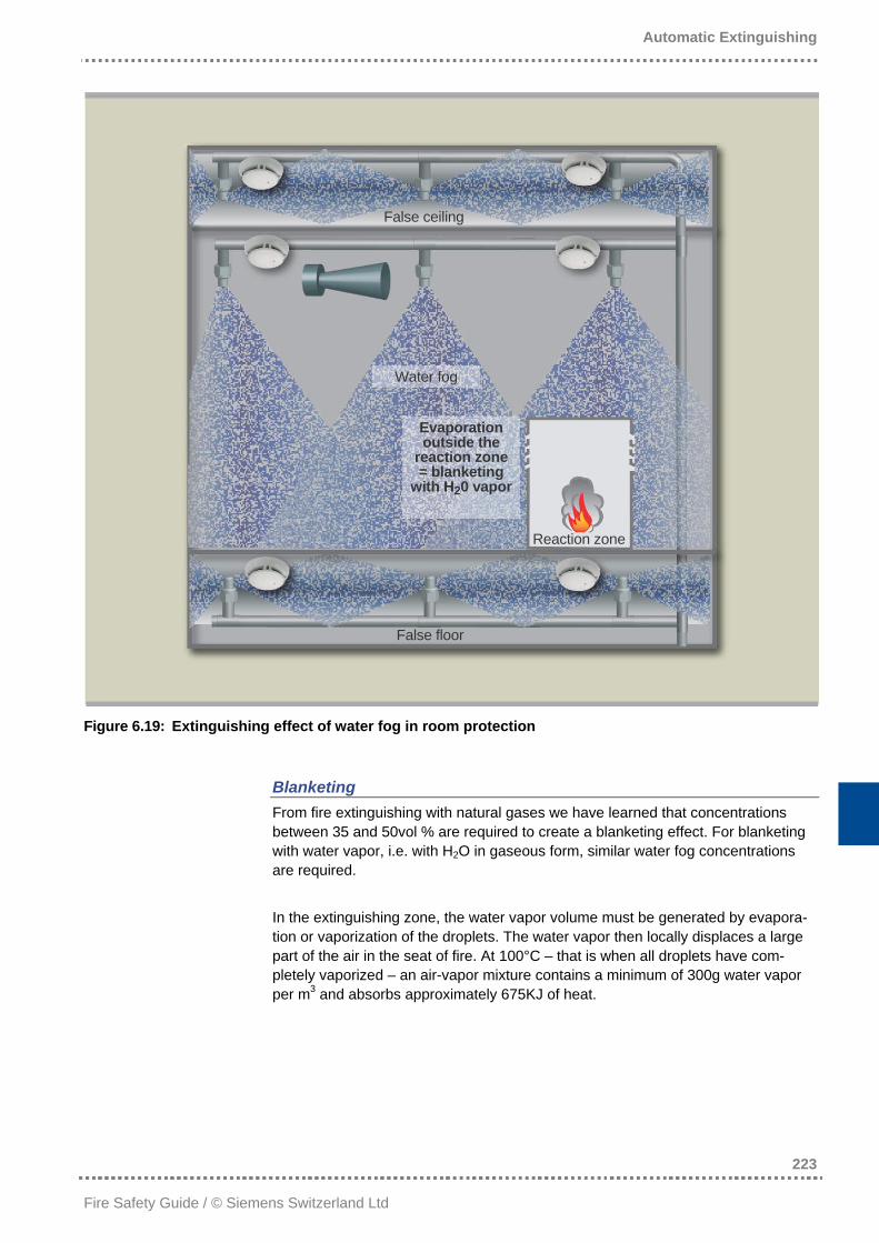
By spraying water to water fog, two effects contribute to a possible fire extinguish-ing: − the cooling effect (heat absorption by vaporization) − the displacement of oxygen (blanketing) Both effects are emphasized by the suppliers of water fog extinguishing systems. In room protection, however – and in contrast to object protection – only the contri-bution of blanketing may be taken into account. With room protection, the seat of fire may emerge at a spot which cannot be reached by the nozzle jet, for example in a covered machine part or a computer housing. This means that the seat of fire would not be charged directly. When the seat of fire is not directly reached by the water fog, only the part of the water droplets transported by air movements can still reach the fire seat. As this water volume is rather moderate, however, the water already vaporizes before it reaches the reaction zone and the fog cannot generate the desired cooling effect in the reaction zone. In addition, the low water volume does not bring about sufficient oxygen displacement. This fact will be handled in detail in the section on blanket-ing.
Automatic Extinguishing
223
Fire Safety Guide / © Siemens Switzerland Ltd
False ceiling
Water fog
Evaporation outside the
reaction zone= blanketing
with H20 vapor
Reaction zone
False floor
Figure 6.19: Extinguishing effect of water fog in room protection
Blanketing From fire extinguishing with natural gases we have learned that concentrations between 35 and 50vol % are required to create a blanketing effect. For blanketing with water vapor, i.e. with H2O in gaseous form, similar water fog concentrations are required. In the extinguishing zone, the water vapor volume must be generated by evapora-tion or vaporization of the droplets. The water vapor then locally displaces a large part of the air in the seat of fire. At 100°C – that is when all droplets have com-pletely vaporized – an air-vapor mixture contains a minimum of 300g water vapor per m3 and absorbs approximately 675KJ of heat.
Automatic Extinguishing
224
Fire Safety Guide / © Siemens Switzerland Ltd
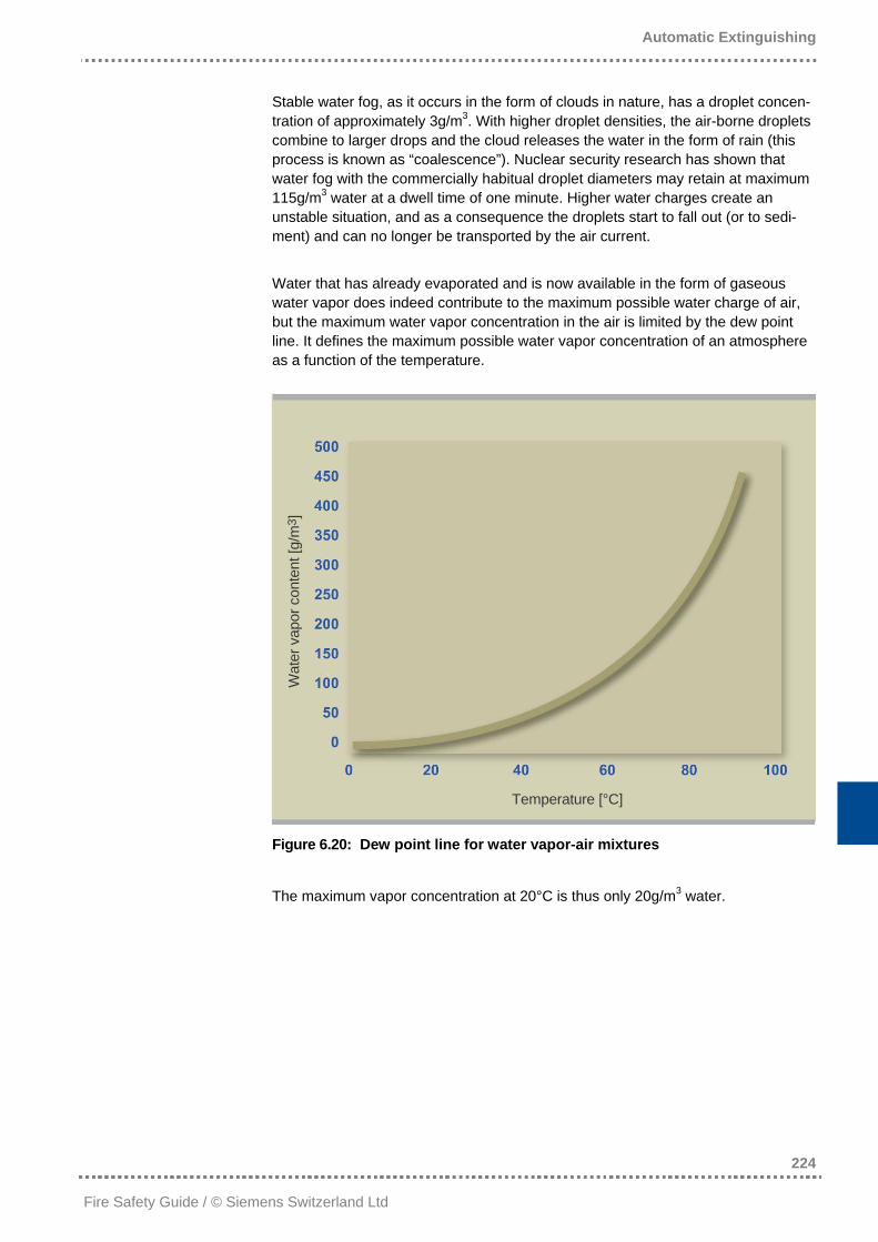
Stable water fog, as it occurs in the form of clouds in nature, has a droplet concen-tration of approximately 3g/m3. With higher droplet densities, the air-borne droplets combine to larger drops and the cloud releases the water in the form of rain (this process is known as “coalescence”). Nuclear security research has shown that water fog with the commercially habitual droplet diameters may retain at maximum 115g/m3 water at a dwell time of one minute. Higher water charges create an unstable situation, and as a consequence the droplets start to fall out (or to sedi-ment) and can no longer be transported by the air current. Water that has already evaporated and is now available in the form of gaseous water vapor does indeed contribute to the maximum possible water charge of air, but the maximum water vapor concentration in the air is limited by the dew point line. It defines the maximum possible water vapor concentration of an atmosphere as a function of the temperature.
Wat
er v
apor
con
tent
[g/m
3 ]
Temperature [°C]
Figure 6.20: Dew point line for water vapor-air mixtures
The maximum vapor concentration at 20°C is thus only 20g/m3 water.
Automatic Extinguishing
225
Fire Safety Guide / © Siemens Switzerland Ltd
This leads to the following conclusions: • At 20°C, the necessary water charge of 300g/m3 definitely cannot be reached
with a combination of droplets and water vapor. • When the droplets of a quasi-static water fog are transported to the fire by
convection only, a fire definitely cannot be extinguished. Such conditions – that do not even constitute the worst case scenario – must be expected with room protection.
• Therefore, the extinguishing effect of water fog systems is not ensured for room protection. Water fog systems cannot be considered extinguishing systems but merely fire-fighting systems. – in contrast to gas extinguishing systems of which the extinguishing effect has been proven even when the seat of fire is not di-rectly accessible for water.
For the sake of completeness, it should be mentioned that at higher temperatures, water vapor densities allow safe extinguishing. To reach the safety level of gas extinguishing systems, i.e. to be able to extinguish any fire at any location, a con-centration of approximately 300g of water per m3 is required. The combination of water droplets and vapor can only reliably build up this amount at room tempera-tures above 80°C. This temperature, however, would not only bring about severe damage to the building structure, combined with the destruction of largely all nor-mal equipment. It would also mean immediate danger to life for any person in the area, as the water condensing on the body surface would lead to severe scalding.
The Sinorix™ GasSpray Solution from Siemens To avoid the disadvantages of the water fog systems in room protection, a combi-nation of water fog and nitrogen proved to be advantageous, in order to ensure that blanketing is sufficiently high even at inaccessible locations. The two agents are combined in the Sinorix™ GasSpray system, leading to the following benefits: − safe extinguishing due to nitrogen − cooling effect of the water vapor The water vapor is thereby calculated on the basis of the risk situation. The lower limit is determined by the goal of reducing the fire seat’s surface temperature from the reaction temperature (TR) below the flaming point (TF) and thus preventing spontaneous re-ignition. Figure 6.21 schematically illustrates the principle of the Sinorix™ GasSpray sys-tem. The water is stored unpressurized in separate containers. Due to the nitrogen, serving as a propellant and simultaneously flowing into the pipe network under pressure, the water is discharged. Both extinguishing agents flow through the same piping system with the same outlet nozzles.
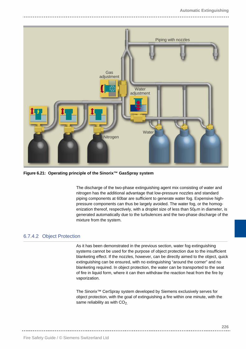
Automatic Extinguishing
226
Fire Safety Guide / © Siemens Switzerland Ltd
Piping with nozzles
Gas adjustment
Water adjustment
Water Nitrogen
Figure 6.21: Operating principle of the Sinorix™ GasSpray system
The discharge of the two-phase extinguishing agent mix consisting of water and nitrogen has the additional advantage that low-pressure nozzles and standard piping components at 60bar are sufficient to generate water fog. Expensive high-pressure components can thus be largely avoided. The water fog, or the homog-enization thereof, respectively, with a droplet size of less than 50µm in diameter, is generated automatically due to the turbulences and the two-phase discharge of the mixture from the system.
6.7.4.2 Object Protection
As it has been demonstrated in the previous section, water fog extinguishing systems cannot be used for the purpose of object protection due to the insufficient blanketing effect. If the nozzles, however, can be directly aimed to the object, quick extinguishing can be ensured, with no extinguishing “around the corner” and no blanketing required. In object protection, the water can be transported to the seat of fire in liquid form, where it can then withdraw the reaction heat from the fire by vaporization. The Sinorix™ CerSpray system developed by Siemens exclusively serves for object protection, with the goal of extinguishing a fire within one minute, with the same reliability as with CO2.
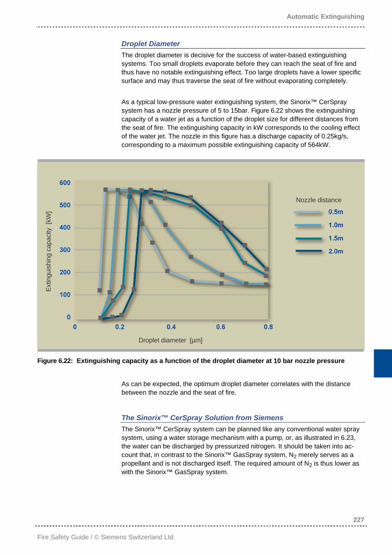
Automatic Extinguishing
227
Fire Safety Guide / © Siemens Switzerland Ltd
Droplet Diameter The droplet diameter is decisive for the success of water-based extinguishing systems. Too small droplets evaporate before they can reach the seat of fire and thus have no notable extinguishing effect. Too large droplets have a lower specific surface and may thus traverse the seat of fire without evaporating completely. As a typical low-pressure water extinguishing system, the Sinorix™ CerSpray system has a nozzle pressure of 5 to 15bar. Figure 6.22 shows the extinguishing capacity of a water jet as a function of the droplet size for different distances from the seat of fire. The extinguishing capacity in kW corresponds to the cooling effect of the water jet. The nozzle in this figure has a discharge capacity of 0.25kg/s, corresponding to a maximum possible extinguishing capacity of 564kW.
Nozzle distance
Extin
guis
hing
cap
acity
[kW
]
Droplet diameter [µm]
Figure 6.22: Extinguishing capacity as a function of the droplet diameter at 10 bar nozzle pressure
As can be expected, the optimum droplet diameter correlates with the distance between the nozzle and the seat of fire.
The Sinorix™ CerSpray Solution from Siemens The Sinorix™ CerSpray system can be planned like any conventional water spray system, using a water storage mechanism with a pump, or, as illustrated in 6.23, the water can be discharged by pressurized nitrogen. It should be taken into ac-count that, in contrast to the Sinorix™ GasSpray system, N2 merely serves as a propellant and is not discharged itself. The required amount of N2 is thus lower as with the Sinorix™ GasSpray system.
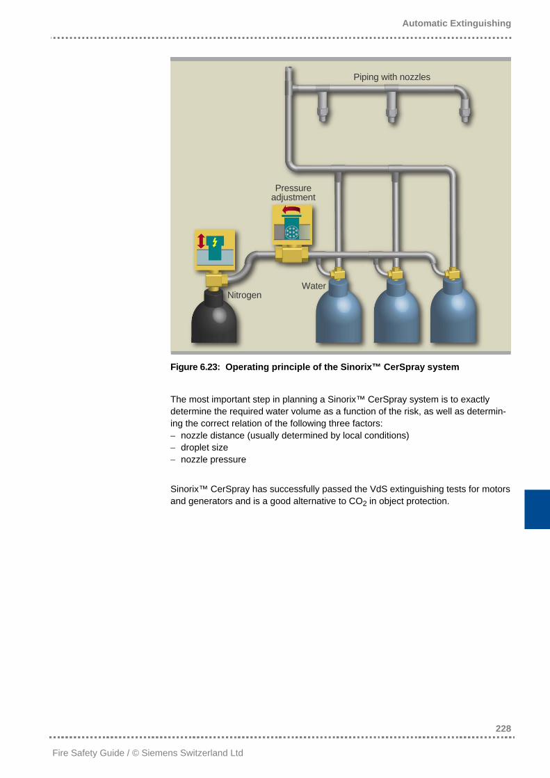
Automatic Extinguishing
228
Fire Safety Guide / © Siemens Switzerland Ltd
Piping with nozzles
Pressure adjustment
Water Nitrogen
Figure 6.23: Operating principle of the Sinorix™ CerSpray system
The most important step in planning a Sinorix™ CerSpray system is to exactly determine the required water volume as a function of the risk, as well as determin-ing the correct relation of the following three factors: − nozzle distance (usually determined by local conditions) − droplet size − nozzle pressure Sinorix™ CerSpray has successfully passed the VdS extinguishing tests for motors and generators and is a good alternative to CO2 in object protection.
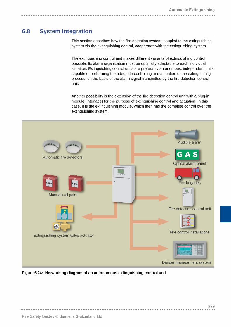
Automatic Extinguishing
229
Fire Safety Guide / © Siemens Switzerland Ltd
6.8 System Integration
This section describes how the fire detection system, coupled to the extinguishing system via the extinguishing control, cooperates with the extinguishing system. The extinguishing control unit makes different variants of extinguishing control possible. Its alarm organization must be optimally adaptable to each individual situation. Extinguishing control units are preferably autonomous, independent units capable of performing the adequate controlling and actuation of the extinguishing process, on the basis of the alarm signal transmitted by the fire detection control unit. Another possibility is the extension of the fire detection control unit with a plug-in module (interface) for the purpose of extinguishing control and actuation. In this case, it is the extinguishing module, which then has the complete control over the extinguishing system.
Audible alarm
Automatic fire detectors Optical alarm panel
Fire brigades
Manual call point
Fire detection control unit
Fire control installations Extinguishing system valve actuator
Danger management system
Figure 6.24: Networking diagram of an autonomous extinguishing control unit
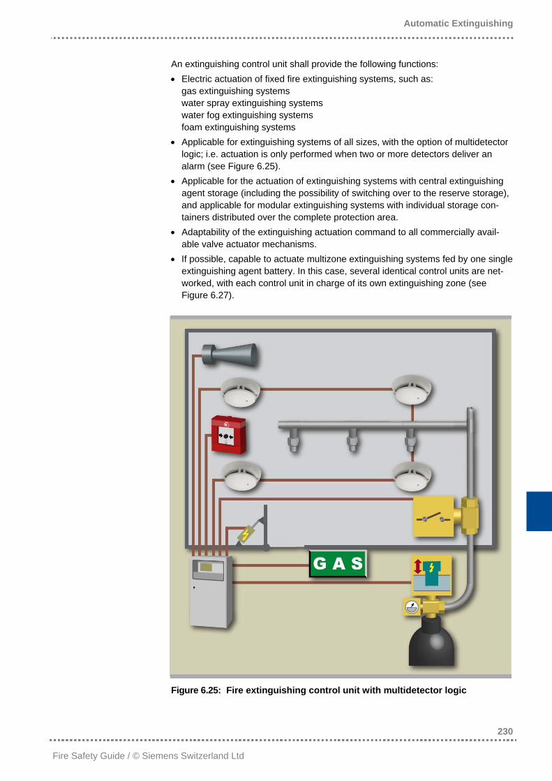
Automatic Extinguishing
230
Fire Safety Guide / © Siemens Switzerland Ltd
An extinguishing control unit shall provide the following functions: • Electric actuation of fixed fire extinguishing systems, such as:
gas extinguishing systems water spray extinguishing systems water fog extinguishing systems foam extinguishing systems
• Applicable for extinguishing systems of all sizes, with the option of multidetector logic; i.e. actuation is only performed when two or more detectors deliver an alarm (see Figure 6.25).
• Applicable for the actuation of extinguishing systems with central extinguishing agent storage (including the possibility of switching over to the reserve storage), and applicable for modular extinguishing systems with individual storage con-tainers distributed over the complete protection area.
• Adaptability of the extinguishing actuation command to all commercially avail-able valve actuator mechanisms.
• If possible, capable to actuate multizone extinguishing systems fed by one single extinguishing agent battery. In this case, several identical control units are net-worked, with each control unit in charge of its own extinguishing zone (see Figure 6.27).
Figure 6.25: Fire extinguishing control unit with multidetector logic
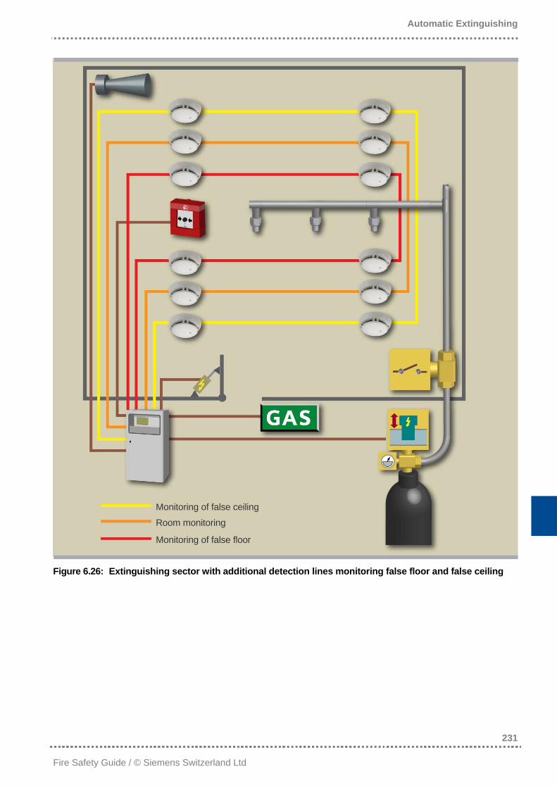
Automatic Extinguishing
231
Fire Safety Guide / © Siemens Switzerland Ltd
Monitoring of false ceiling
Room monitoring
Monitoring of false floor
Figure 6.26: Extinguishing sector with additional detection lines monitoring false floor and false ceiling
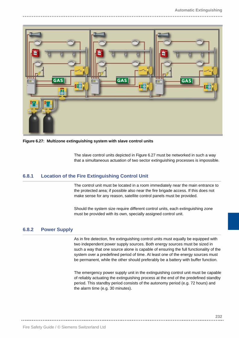
Automatic Extinguishing
232
Fire Safety Guide / © Siemens Switzerland Ltd
Figure 6.27: Multizone extinguishing system with slave control units
The slave control units depicted in Figure 6.27 must be networked in such a way that a simultaneous actuation of two sector extinguishing processes is impossible.
6.8.1 Location of the Fire Extinguishing Control Unit
The control unit must be located in a room immediately near the main entrance to the protected area; if possible also near the fire brigade access. If this does not make sense for any reason, satellite control panels must be provided. Should the system size require different control units, each extinguishing zone must be provided with its own, specially assigned control unit.
6.8.2 Power Supply
As in fire detection, fire extinguishing control units must equally be equipped with two independent power supply sources. Both energy sources must be sized in such a way that one source alone is capable of ensuring the full functionality of the system over a predefined period of time. At least one of the energy sources must be permanent, while the other should preferably be a battery with buffer function. The emergency power supply unit in the extinguishing control unit must be capable of reliably actuating the extinguishing process at the end of the predefined standby period. This standby period consists of the autonomy period (e.g. 72 hours) and the alarm time (e.g. 30 minutes).
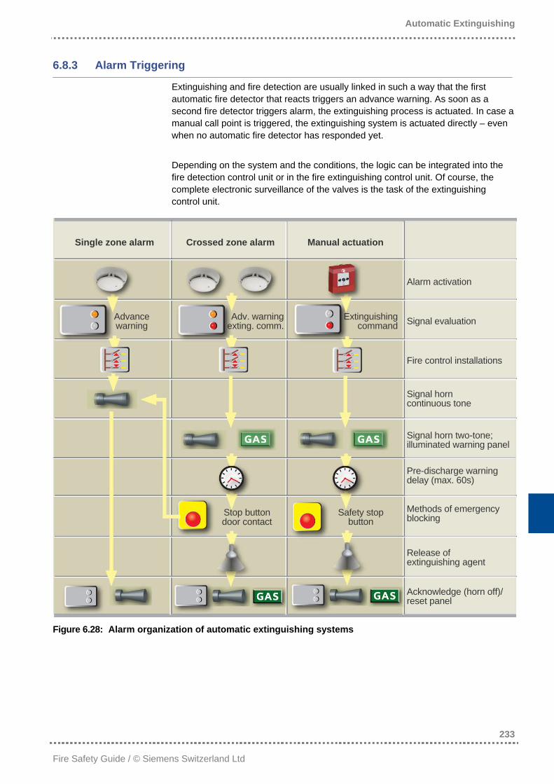
Automatic Extinguishing
233
Fire Safety Guide / © Siemens Switzerland Ltd
6.8.3 Alarm Triggering
Extinguishing and fire detection are usually linked in such a way that the first automatic fire detector that reacts triggers an advance warning. As soon as a second fire detector triggers alarm, the extinguishing process is actuated. In case a manual call point is triggered, the extinguishing system is actuated directly – even when no automatic fire detector has responded yet. Depending on the system and the conditions, the logic can be integrated into the fire detection control unit or in the fire extinguishing control unit. Of course, the complete electronic surveillance of the valves is the task of the extinguishing control unit.
Single zone alarm Crossed zone alarm Manual actuation
Alarm activation
Advance warning
Adv. warningexting. comm.
Extinguishing command Signal evaluation
Fire control installations
Signal horn continuous tone
Signal horn two-tone; illuminated warning panel
Pre-discharge warning delay (max. 60s)
Methods of emergency blocking Stop button
door contact Safety stop
button
Release of extinguishing agent
Acknowledge (horn off)/ reset panel
Figure 6.28: Alarm organization of automatic extinguishing systems
Automatic Extinguishing
234
Fire Safety Guide / © Siemens Switzerland Ltd
6.9 Maintenance and Servicing
To preserve the functional reliability of extinguishing systems, regular maintenance and revisions are indispensable. This is the only way to ensure undisturbed opera-tional reliability. Maintenance comprises actions for maintaining the nominal state of the extinguish-ing system, especially to ensure its operability. It is recommended to have extin-guishing systems serviced at least once a year. Maintenance and revisions should be performed by the system installer or the respective authority. The type and scope of maintenance work strongly depends on the system type. The customer should name a person responsible for the extinguishing system’s servicing, preferably an employee who regularly performs the checks specified in the instructions. Of course, these checks must be performed more frequently than the maintenance work and revisions. Furthermore, the person in charge shall initiate the necessary repair work and record all actions and events. When the complete extinguishing system, or parts thereof, shall be temporarily put out of operation, special fire protection actions have to be taken. These measures must ensure that a fire can be detected as early as possible and can be effectively fought with the extinguishing devices to be provided.
Automatic Extinguishing
235
Fire Safety Guide / © Siemens Switzerland Ltd
6.10 Profitability and System Evaluation
Automatic extinguishing systems constitute an essential and generally indispensa-ble part of fire protection concepts. The extinguishing method applied must be determined by an expert, as there are no universal solutions: Too many influencing factors are involved in the decision-making process. Nevertheless, some experiences have been made that can be easily imparted: • The use of gas mixtures has no advantage over extinguishing with natural
gases. • The correct design and sizing of the system cannot generally be controlled by
the customer and is nevertheless a decisive factor. Competence and experience of the system supplier are thus of utmost importance, i.e. the correct nozzle pressure, for example, can significantly improve the extinguishing result of cer-tain extinguishing systems.
• A system supplier with a comprehensive product portfolio is hardly tempted to provide any available system instead of choosing the best suited system that is unfortunately not available at the moment.
An extinguishing system is an investment in the building’s entire life cycle and even in the case of object protection, it is not limited to a few years. For this reason, the investment should take into account that correspondingly long system serviceability is provided.