5kV HIGH VOLTAGE INSULATION TESTER...-1-1. Safety Precautions Electricity can cause severe injuries...
28
5kV HIGH VOLTAGE INSULATION TESTER INSTRUCTION MANUAL Test Equipment Depot - 800.517.8431 99 Washington Street Melrose, MA 02176 TestEquipmentDepot.com
Transcript of 5kV HIGH VOLTAGE INSULATION TESTER...-1-1. Safety Precautions Electricity can cause severe injuries...

5kV HIGH VOLTAGE INSULATION TESTER
INSTRUCTION MANUALTest Equipment Depot - 800.517.8431
99 Washington Street Melrose, MA 02176
TestEquipmentDepot.com

Index1. Safety Precautions..................................................2. Overview.................................................................3. Features..................................................................4. Specifications..........................................................5. Connections............................................................6. Instrument layout....................................................7. Measuring procedure..............................................8. Charge....................................................................9. Maintenance & repair..............................................10. Interface connection and operation.......................
Page1-223456
7-141516
17-24

-1-
1. Safety PrecautionsElectricity can cause severe injuries even with low voltages orcurrents.Therefore it is extremely important that you read the followinginformation before using your high voltage insulation tester.a. This Instrument must only be used and operated by a
competent trained person and in strict accordance with theinstructions. we will not accept liability for any damage or injurycaused by misuse or non compliance with instructions andsafety procedures.
b. This instrument must not be used on live circuits. Ensureall circuits are de-energised before testing. see paragraphfor details of built-in warning features should your highvoltage insulation tester be connected to a live system.
c. Always inspect your high voltage insulation tester and testleads before use for any sign of abnormality or damage. If anyabnormal conditions exist (broken test leads, cracked case,display faulty etc...) do not attempt to take any measurementor use the tester. Return your high voltage insulation tester toyour nearest distributor for service.
d. Your high voltage insulation tester has been designed withyour safety in mind. However, no design can completelyprotect against incorrect use. Electrical circuits can bedangerous and / or lethal when a lack of caution or poor safetypractice is used.
e. Pay attention to cautions and warnings which will inform you ofpotentially dangerous procedures.
f. Your high voltage insulation tester has a live circuit warningbeeper. If it is connected to a live circuit, a rapid pulsatingbleep will be heard. DO NOT proceed to test and immediatelydisconnect the instrument from the circuit. In addition yourtester will display the warning message.

g. Rated environmental conditions:(1) Indoor use.(2) Installation Category IV .(3) Pollution Degree 2.(4) Altitude up to 2000 meters.(5) Relative humidity 80% max.(6) Ambient temperature 0°C~40°C.
h. Observe the international Electrical Symbols listed below :
lnl Meter is protected throughout by double insulation or reinforced insulation.
& Warning ! Risk of electric shock.
&, Caution ! Refer to this manual before using the meter.
,½ Earth
2. Overview
This is a SkV high voltage insulation tester which has outputvoltages of 500V, 1 000V, 2500V, 5000V.The top line of the display shows the elapsed time at the startof the test. Digital readout of the total time will remain displayedeven after testing has ceased.This instrument displays a voltage warning and sounds when ACor DC is present before injecting the test voltage.
-2-
Test Equipment Depot - 800.517.8431
99 Washington Street Melrose, MA 02176
TestEquipmentDepot.com

-3-
3. Features 2 Lines × 16 Characters LCD Microprocessor-controlled Tests insulation resistance up to 10 TΩ 4 Insulation test voltages:
500V, 1000V, 2500V, 5000V AC/DC Voltmeter Short-circuit current up to 5mA PI (Polarization Index) indication DAR (Dielectric Absorption Ratio) indication Auto-ranging on all insulation ranges Optical USB to RS-232 data transmission Well isolated from contact Well protected from surges 2 built-in optical LEDs for data transfer Visual and audio warning of external voltage presence
(≥30Vac or ≥30Vdc) Auto-hold function to freeze reading Overload protection Adjustable testing duration: 1~30 minutes Internal memory for data storage Displays testing duration for insulation measurement Auto-off function 200 measurement results can be saved in memory and
recalled on display

-4-
4. SpecificationsTest Voltage 500V, 1000V, 2500V, 5000V
Insulation resistance
1TΩ / 500V2TΩ / 1000V5TΩ / 2500V10TΩ / 5000V
Accuracy
0~100GΩ / 500V0~200GΩ / 1000V0~500GΩ / 2500V0~1000GΩ / 5000V
±(5.0%rdg + 5dgt)
100G~1TΩ / 500V200G~2TΩ / 1000V500G~5TΩ / 2500V1000G~10TΩ / 5000V
±12%rdg
Resolution
1000MΩ: 1MΩ10GΩ: 0.01GΩ100GΩ: 0.1GΩ1TΩ: 1GΩ10TΩ: 10GΩ
Short circuit current up to 5mAPI (Polarization Index) √DAR (Dielectric Absorption Ratio) √
Voltmeter
ACV: 30~600V (50/60Hz)DCV: 30~600VAccuracy: ±(2.0%rdg + 3dgt)Resolution: 1V
Current measurement 0.5nA ~ 0.55mA (Depending on the insulation resistance)
Power source 1.5V "C" × 8 Alkaline batteriesDimensions 330(L) × 260(W) × 160(D)mmWeight Approx. 4268g (battery included)
Safety standardEN 61010-1 CAT IV 600VEN 61010-2-030 EN 61326-1
Accessories
Instruction manual Test leads Data transmission cable Compact disk (CD) for PC interfaceAlligator clips Batteries Test report


-7-
7. Measuring procedureThis tester provide five main functions and four minor functions:Main Functions:1. 500V voltage insulation resistance test.2. 1kV voltage insulation resistance test.3. 2.5kV voltage insulation resistance test.4. 5kV voltage insulation resistance test.5. AC/DC voltage measurement.
Minor functions:Function 1 Date/time adjustment.Function 2 Measurement time setting.Function 3 Display data stored.Function 4 Delete data stored.
(A) Insulation resistance measurement test (main function)Note:
1. Before test performed, be sure that no voltage is madeon the specimen. If voltage exists therein, remove thepower supplied.
2. To secure operator’s safety, check if there is any damageon the tester or test cable.
3. During the test, do not touch the metal on the specimensurface or test cable.
4. Wear insulation gloves and rubber shoes while operatingthis high-voltage measuring instrument.
(a) Checks before test is performed:Press the power switch and check if power supply issufficient? If insufficient, "Low Battery" will be displayed onthe LCD display. Please replace with new Alkaline batteries.


5. Read the test value from LCD display.
6. To store the data, press @ (ENTER/SAVE); LCD displaysthe picture shown in below:
&Note:
003 5451..J/0. 5KI..J
8916 00:35
When do the insulation test, always connect the test leads to the object we want to measure before pressing the TEST button. Do not press the TEST button in advance.
(B) Measure voltage (Voltage Meter) -(main function)
1. Switch ® the function rotary switch to turn on power andselect AC/DC voltage measurement .
2016-08-16 10:10
ACI..J 1101.J 60HZ
2. Read the data measured from LCD display.
2016-08-16 10:10
TOhM 5KU/10TQ
-9-
Test Equipment Depot - 800.517.8431
99 Washington Street Melrose, MA 02176
TestEquipmentDepot.com


-14-
(G) Introduction of other functions1. Dielectric absorption ratio (DAR):
Ratio of insulation resistance between 1-min and 30-sec1-min insulation resistance
DAR :30-sec insulation resistance
2. Polarization index (PI):Ratio of insulation resistance between 10-min and 1-min
10-min insulation resistance PI :
1-min insulation resistance
Lower insulation resistance tested takes longer test time, which would deteriorate the specimen. Thus, higher DAR or PI (as close to 1) would create better insulation grade of specimen.
Operation:During the test run, wait for one minute, DAR will bedisplayed automatically; wait for 10 minutes, PI will be displayed automatically.
3. AUTO OFF:System will shutdown automatically after 3 minutes withoutoperation.
Test Equipment Depot - 800.517.8431
99 Washington Street Melrose, MA 02176
TestEquipmentDepot.com

-15-
8. Battery replacementWhen "Low Battery" info shows on the LCD.Disconnect the test leads from the 5kV high voltage insulationtester, and turn off the power.Replace with new Alkaline batteries.(1.5V "C" × 8)

-16-
9. Maintenance & repair(A) To avoid and electric-shock or device damage, do not wet
inner part of the tester.(B) Avoid the tester from being dropped down that would
damage or disconnect devices apart.(C) Wipe the tester surface with soft, dry cloth and mild
detergent. Prohibit from using sand paper or solvent.Note:1. This tester is HV operated; user should not open the
outer casing. If any damage occurs, take the tester back tomanufacturer for repair.
2. If the tester is not used for over 60 days, remove thebatteries for storage.

-17-
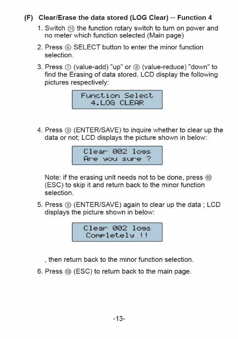
10. Data Transmission Interface connection andoperation
(A) 5KV Insulation Tester Installation Steps:1. This 5KV Insulation Tester Installation program will be
installed on the computer automatically.
2. Click the “Next” key to set.
3. If you want to install a different folder, click Browse, andselect another folder.If it’s not necessary, click the “Next” key.

-18-
4. Click the “Next” key.
5. It will show the information of all files are Installing to yourpersonal computer.
Test Equipment Depot - 800.517.8431 - 99 Washington Street Melrose, MA 02176
TestEquipmentDepot.comm

-19-
6. It will show the information of Insulation tester has beensuccessfully installed and then click “Finish” key.
(Note: If your personal computer system is Windows 7, it will indicate the driver automatically. It’s necessary to install the driver if your computer system is not windows 7, then the driver is in the compact disk (CD). The directory is “ E:USB DRIVER/CDM 2.08.24 WHQL Certified x 86-32 bit”.)
Test Equipment Depot - 800.517.8431
99 Washington Street Melrose, MA 02176
TestEquipmentDepot.com


-24-
⑤ Click the "Chart Display" button to see the chart, as the figure is below:
This Chart Display can also show Resistance and Current diagram by clicking the dot
⑥ Click the "Save Log" button to the file, as the figure is below:

Test Equipment Depot - 800.517.8431
99 Washington Street Melrose, MA 02176
TestEquipmentDepot.com

T05A