
5G White Paper: Data Driven and Intent Aware Smart ...
63
Transcript of 5G White Paper: Data Driven and Intent Aware Smart ...


5G White Paper: Data Driven and Intent Aware Smart Wireless Network
Data Driven and Intent Aware
Smart Wireless Network
2019

5G White Paper: Data Driven and Intent Aware Smart Wireless Network
Executive Summary
To accommodate a wide range of scenarios and service requirements, the 5G network is becoming
more agile, and inevitably, more complicated, thus posing great challenges to network management
and radio resource optimization. Intelligence is expected to be introduced in wireless network for all
the domains and all levels, from local, edge to the cloud. Data analytics, machine learning and
artificial intelligence are identified as the key drivers for the intelligence evolution and revolution in
the wireless network. Data driven smart wireless network usage scenarios and network architecture
are being heatedly discussed and investigated recently both in the wireless network industry and
academia. “Smart and Simplicity” become the industry consensus for 5G and future network.
“Smart” requires the network to dynamically adapt to the diversified scenarios and services to
efficiently boost both spectrum efficiency, energy efficiency and offer the consistency the user
experience. “Simplicity” poses the requirements of network automation to significantly reduce the
network operation and maintenance human labor and cost.
This white paper investigates the data driven and intent aware smart wireless network. It is an update
and evolution of the previous whitepapers “Wireless Big Data for Smart 5G” and “Wireless Big Data and
AI for Smart 5G & Beyond ”, where the reference architecture and use case are comprehensively studied.
In this white paper, data driven wireless network is firstly introduced and reviewed. Different
categories of typical use cases and potential solution are described, from the network management
and operation to MEC optimization, the network resource optimization and the intelligent
transmission technologies. The ML and data analytics algorithms utilized in the all the use cases of
the series of whitepapers are also discussed and summarized to provide some insight for the
researcher on the future works. Furthermore, intent aware wireless network is proposed and
investigated to achieve the network “simplicity” leveraging the data driven network intelligence. The
concept and motivation of the intent aware network is firstly briefly described. The reference
architecture of intent driven is investigated with discussion of the intent expression. Besides, the key
issues, challenges and the intent service evolution roadmap are presented. Last but not the least, the
standardization progress are discussed.
We wish this white paper can provide readers with some valuable insights for industry on the data
driven and intent aware smart wireless network and help to accelerate the process of smart wireless
network.

5G White Paper: Data Driven and Intent Aware Smart Wireless Network
1 中文摘要
为了适应多种多样的场景和服务需求,5G网络正变得越来越灵活,也不可避免地变得越来越复杂,给
网络管理和无线资源优化带来了巨大挑战。为了应对挑战,智能有望被引入到从本地,边缘到云的无线网
络的所有域和所有层级。“智能极简”成为5G和未来网络的行业共识。“智能”要求网络动态适应不同的
场景和服务,以有效地提高频谱效率,能效并提供定制化的极致用户体验。“极简”提出了网络自动化的
需求,以显着减少网络运维的人力和成本。
本白皮书研究了数据驱动和意图感知的智能无线网络。这是对先前“无线大数据和智慧5G”和“无线
大数据与人工智能使能的智慧5G+”系列白皮书的更新和发展,先前两本白皮书中对数据驱动的智能网络参
考架构和用例均进行了研究和分享。在本白皮书中,首先回顾了数据驱动的无线网络,更新了网络运维、
边缘计算优化、网络资源优化和智能传输技术的典型用例及潜在解决方案的进展;其次还进一步分析了智
能无线网络用例所使用的机器学习、数据分析算法及数据需求,希望能为研究人员对未来的工作提供一些
参考。
本白皮书中还进一步提出了意图感知(或者意图驱动)的无线网络,研究如何简化无线网络管理接口,
利用数据驱动的智能化手段将网络管理意图自动转换为复杂的网络管控操作,以更好的实现网络自治化,
减少运维人员的人力和工作复杂度,并进一步面向垂直行业提供更简易的网络管理能力开放。文中首先简
要描述了意图感知网络的动机和概念,并通过讨论意图感知的无线网络场景和用例,进一步研究了意图感
知无线网络的参考架构。其次提出了意图感知无线网络的关键问题和挑战,并对意图感知无线网络的演进
路线进行了讨论。最后,本白皮书总结了ITU-T/3GPP/ETSI等在数据采集、数据分析、机器学习、意图驱动
与智能5G网络相关的标准化进展。
我们希望本白皮书可以和读者分享有关数据驱动和意图感知的智能无线网络的一些有价值的技术探索
以及学术、产业界的最新进展,为学术界及产业界在研究、规划和设计5G 网络智能化相关技术、产品和解
决方案时提供一些参考和指引,从而加快智能无线网络的技术发展与产业化落地。

5G White Paper: Data Driven and Intent Aware Smart Wireless Network
Table of Contents
2 Smart Wireless Network ...................................................................................................................................... 1
2.1 Data Driven Wireless Network ................................................................................................................ 1
2.2 Intent Aware Wireless Network .............................................................................................................. 2
3 Data Driven Wireless Network ............................................................................................................................ 4
3.1 Overall Introduction ................................................................................................................................. 4
3.2 Network Management Optimization........................................................................................................ 4
3.2.1 Use case 1: Anomaly Detection with KPIs .................................................................................. 4
3.2.2 Use case 2: Anomaly Diagnosis with KPIs ................................................................................. 7
3.2.3 Use case 3: Smart Carrier Licence Resource Scheduling ............................................................ 9
3.2.4 Use case 4: Geo Data Enhanced Coverage Estimation and Network Planning ......................... 13
3.3 MEC Optimization ................................................................................................................................. 14
3.3.1 Use case 5: Intelligent MEC Caching Optimization .................................................................. 14
3.4 Network Resource Optimization ........................................................................................................... 16
3.4.1 Use case 6: AI Empowered QoE Optimization ......................................................................... 16
3.4.2 Use case 7: Smart Resource Management for Network Slicing ................................................ 17
3.4.3 Use case 8: Data Driven Predictive Resource Allocation .......................................................... 22
3.4.4 Use case 9: Big Data Analysis for Handover Optimization in Massive-MIMO Cellular Systems
30
3.5 Radio Transmission Technologies ......................................................................................................... 35
3.5.1 Use case 10:Deep learning aided codebook design for grant-free NOMA ................................ 35
3.6 Discussion on the wireless big data and AI/ML algorithms for wireless network applications ............ 38
4 Intent Aware Wireless Network ........................................................................................................................ 40
4.1 Motivation ............................................................................................................................................. 40
4.2 Use Cases for intent aware wireless network ........................................................................................ 42
4.2.1 Use Case 1: Intent driven network service provision ................................................................ 42
4.2.2 Use Case 2: Intent driven network provision and assurance for 5G vertical services ............... 42
4.2.3 Use Case 3: intent/policy driven network optimization for user QoE assurance ....................... 43
4.2.4 Use Case 4: Intent driven network performance optimization ................................................... 44

5G White Paper: Data Driven and Intent Aware Smart Wireless Network
4.2.5 Use Case 5: intent driven traffic steering optimization .............................................................. 45
4.3 Reference Architecture for the intent aware wireless network .............................................................. 46
4.4 Intent Expression Model ........................................................................................................................ 47
4.5 Technical Key Issues ............................................................................................................................. 48
4.6 Intent Service Evolution Consideration ................................................................................................. 49
5 Standards Progress in 3GPP/ITU/ETSI and Consideration ............................................................................... 49
5.1 ITU-T ML5G ......................................................................................................................................... 49
5.2 3GPP ...................................................................................................................................................... 50
5.2.1 SA2 ............................................................................................................................................ 50
5.2.2 SA5 ............................................................................................................................................ 50
5.2.3 RAN3 ......................................................................................................................................... 52
5.3 ETSI ENI ............................................................................................................................................... 52
6 Summary ............................................................................................................................................................ 53
7 Reference ........................................................................................................................................................... 53
Acknowledgement ..................................................................................................................................................... 54
Abbreviation .............................................................................................................................................................. 55

5G White Paper: Data Driven and Intent Aware Smart Wireless Network
1
2 Smart Wireless Network
2.1 Data Driven Wireless Network
5G is on the road of commercialization all around the world. During the standardization of 5G, the network is
defined to satisfy all the requirement of eMBB, URLLC and mMTC, so it is also called internet of everything. This
means the network will become more sophisticated than ever, more scenario and larger number of functionalities
will be used in the network. Based on this requirements and premise, it will be a very tough to use traditional
method to manage and configure the network. So some new technologies are introduced to the wireless
communication of 5G network. Big data analytics and machine learning are envisioned to enable the automation
operation and maintenance of the future wireless network and also help to ensure customized user experience.
Figure 1.1 shows the general close loop flow of data analytics. Which mainly consists the following steps: 1) data
collection and context aware; 2) Diagnostic analysis;3) predictive analysis; 4) Reasoning and decision making.
Figure 1.1 Data analytics closed loop control
“Data Driven” is widely recognized as the key features of 5G and future network by the mobile network industry.
Data analytics and machine learning are expected to empowered the network with the following capabilities;
Reliable prediction: The vase multi-dimension data collected from the network enables the capability to
predict the network traffic, network anomaly, service pattern/type, user trajectory/position, service quality of
experience, radio finger print, interference, etc. These predictions will undoubtedly empower the proactive network
management and control, leading to significantly improved network resource and energy efficiency and customized
user experience assurance.
Advanced network optimization and decision: Driven by the collected data from the real network, data

5G White Paper: Data Driven and Intent Aware Smart Wireless Network
2
analytics and machine learning can help to efficiently solve massive of problems in the 5G network which are
usually hard to model or suffering great computation complexity due to the extremely high dimensions or
NP-hardness.
The concept, use cases and architecture framework of data driven wireless network are extensively discussed in the
previous versions of the whitepaper [1][2].Data analytics and machine learning can be implemented and utilized in
different management and control loops of the wireless network. In the reference architecture of [1-3], various
levels of data analytics functionalities were introduced in the wireless network, including the management plane,
core network and RAN. Based on which, diversified use cases are supported [1,2,4].More and more research
academics, industry companies and SDOs are joining the work on data driven smart wireless network. Great
progress had been made in both standardization and test/trials/application in the commercial network or 5G test
network. The main updates and progress are described in detail in the section 2 and section 4.
2.2 Intent Aware Wireless Network
Compared with previous data driven network, the intent aware network mainly adjusts and optimizes according to
the intention of human and machine instead of data. Data driven technology is one of the important fundamental
technologies to automatically realize the management intent. With the requirements described in intent, the
data-driven wireless network may automatically uses the knowledge learned from historical data to figure out the
actions based on currently network state.
In intent aware wireless network, the network operation staff uses controlled language or DSL to express the
management goals, without describing how to accomplish the goals. The network is responsible to adjust and
optimize itself to satisfy the input intent. Specifically, the network needs to:
⚫ Enable new digital business. It needs to have the flexibility to quickly align with rapidly changing business
objectives.
⚫ Be easier to configure, operate and maintain in large number of differential usage scenario with growing scale
and complexity. Current operational modes are not scalable or sustainable to fit the requirement.
⚫ Provide full visibility in terms of how a network is operating and providing assurance to support the desired
business and be able to identify any discrepancies and recommend correction.
⚫ Identify and neutralize security threats before they cause harm. Multi-cloud, IoT and mobile adoption open up

5G White Paper: Data Driven and Intent Aware Smart Wireless Network
3
new threats that the network needs to be constantly protect against.
Intent aware network offers a significant paradigm shift in how networks are planned, designed, operated and
optimized. In the past, the management intents are translate to device-level configurations manually, and the
network management staff is responsible to assure the network to reach the desired status. The network designer or
operator had to manually derive individual network-element configurations to support the desired intent such as, “I
want these servers to be reachable from these branches”. Then, specific configurations (e.g., VLAN, security rules
etc.) are derived and configured on each device manually. The intent aware network replaces conventional
management and optimization activities that requires manually derived network-element configurations with the
intent expression that just describes “what to do” rather than “how to do”. The network will itself automatically
figure out “how to do”.
Figure 1.2 Conceptual description of Intent aware network
Figure 1.2 shows the conceptual description of intent aware wireless network.
⚫ The translation function is about the characterization of intent. It enables network operators to express intent in
a declarative format, expressing what the expected networking behavior is that will best support the business
objectives, rather than how the network elements should be configured to achieve that outcome.
⚫ The action function captured intent then needs to be interpreted into policies that can be applied across the
network. The action function installs these policies into the physical and virtual network infrastructure using
Human(thoughs)
Machine
Translation
Activation
Network(wired, wireless)
Thoughts and Intent
Capture business intent, translate to policies, check integrity
Orchestrate policies, configure system
Feedback network parameter and status
Assurance
Continuous verification, correct actions

5G White Paper: Data Driven and Intent Aware Smart Wireless Network
4
network wide automation.
⚫ The assurance function continuously monitors and checks that the expressed intent is enforced by the network
at any point in time, which maintains a continuous validation-and-verification loop. The network status and
large scale configuration parameter is sent back to translation module to correct the status of the network to
satisfy the intent.
3 Data Driven Wireless Network
3.1 Overall Introduction
To foster the exchange of ideas, sharing of research on data driven smart wireless network, three white papers are
published in 2017 and 2018.[1-3]. The white paper introduced the use cases, potential solutions, reference
architecture, procedure and platform designs on the wireless big data and AI driven network. Based on the previous
versions of the white paper, this white paper mainly focus on the expansion of data driven use cases and also
introduces the intent aware smart wireless network.
In this section, ten use cases are described to update the progress and further demonstrate promising research
topics of data driven smart wireless network from four aspects: network management optimization, MEC
optimization, network resource optimization and radio transmission technologies. The AI algorithms
3.2 Network Management Optimization
3.2.1 Use case 1: Anomaly Detection with KPIs
KPIs anomaly detection is quiet important for network maintenance. Due to the complexity of 5G network which
contains numerous radio nodes and other components, there are a huge amount of KPI data to be monitored, which
can be time consuming, error-prone and even impossible. A ML-based anomaly detection method is considered, as
shown in Figure 2.1. It is essentially composed of three modules: anomaly detection, anomaly scoring and feedback
module. The anomaly detection model and scoring model are trained with off-line data, using the batch computing
engine and training engine in Figure 2.2. Then, the KPIs data are detected online based on the streaming computing
engine. The KPI data point whose anomaly score is higher than a predefined threshold will be noticed to the O&M
engineer and the engineer can label it whether abnormal, providing feedback to the training module to improve the
algorithm performance.

5G White Paper: Data Driven and Intent Aware Smart Wireless Network
5
Figure 2.1 An illustration of ML-based anomaly detection method
The KPIs represent varied characteristics because of the diverse characteristics of network modules. For example,
some KPIs show periodicity while others do not; some KPIs have trend, while the other KPIs are stable. A two
stage modelling method is investigated to deal with the huge challenge for comprehensive modelling all kinds of
KPIs. As shown in Figure 2.2, the first stage is the classification stage, where a time series clustering algorithm is
formulated to classify the KPIs based on their structure characteristics. In the second stage, the module selects an
appropriate time series model for each category of KPI, predicting the normal baseline at each time point for a KPI.
In the online detection, a value would be denoted as anomaly if it exceeds the baseline.
Figure 2.2. A demonstration of two stage time series modelling method
The structural features based time series clustering method can be used to reduce the complexity of clustering.
Firstly, the time series are classified into two main categories, with significant periodicity and non-significant
periodicity, based on Fourier transformation. Secondly, the K-means algorithm is used to cluster the time series in
each main category base on seven features extracted from the KPI series. In the first stage, the frequency amplitude
spectrum of a KPI is calculated by discrete Fourier transformation (DFT) as follows:
21
0
[ ] ( ) , 0 1N j kn
N
n
F k x n e k N− −
=
= −.
Denoting the maximum, mean and standard deviation of the amplitude spectrum as maxF
, meanF
, stdF
.
If satisfying the following condition:
max mean stdF F c F + ,
where c is a predefined coefficient larger than 3, the KPI would be classified as significant periodicity,
otherwise non-significant periodicity.

5G White Paper: Data Driven and Intent Aware Smart Wireless Network
6
When a KPI has been classified, a suitable time series model is selected according to its characteristic. There
are a number of candidate models available, such as density estimation, Olympic model, regression model,
Holt-Winters model, auto-regressive integrated moving average (ARIMA) [5]. Fox example, if a KPI contains
trend and periodicity, the Holt-Winters model is able to model it as following:
* *
1 1
* *
1 1
* *
1 1
( ) (1 )( )
( ) (1 )
( ) (1 )
t t t m t t
t t t t
t t t t t m
l x s l b
b l l b
s x l b s
− − −
− −
− − −
= − + − +
= − + −
= − − + − ,
where tl , tb , ts are the level component, trend component and seasonal component respectively, and m is
the period of time series. The forecasting value at h step would be:
|m
t h t t t t m hx l hb s ++
− += + + ,
where 1mod)1( +−=+ mhhm
. When the prediction value and fitting errors in historical data are calculated,
the normal baseline could be formulated as:
| 1 /2
| 1 /2
t h
t h
L
t h t H
U
t h t H
x x z
x x z
+
+
+ −
+ −
= −
= + ,
where 𝑧1−α/2
is the 1 − α/2
percentile of standard Gaussian distribution, and H is the standard deviation
of fitting errors in historical data. A common used value for α is 0.003. Figure 2.3 is an illustration of the
computed thresholds for a KPI.
Figure 2.3. An illustration of time series modelling by Holt-Winters. The upper figure represents the true value (blue curve) and
fitting value (green curve) in historical data; the lower figure represents the true value (blue curve) and the predicted thresholds (red
curve) in the following day.
The other types of KPI can be modeled by other time series models. For example, the data with significant
5G White Paper: Data Driven and Intent Aware Smart Wireless Network
7
randomness could be modeled by density estimation, rather than Holt-Winter model. The anomaly scoring model is
critical to reduce the false alarm and facilitate the O&M engineer to focus on important events. The detailed
algorithm is a planning research topic in the future.
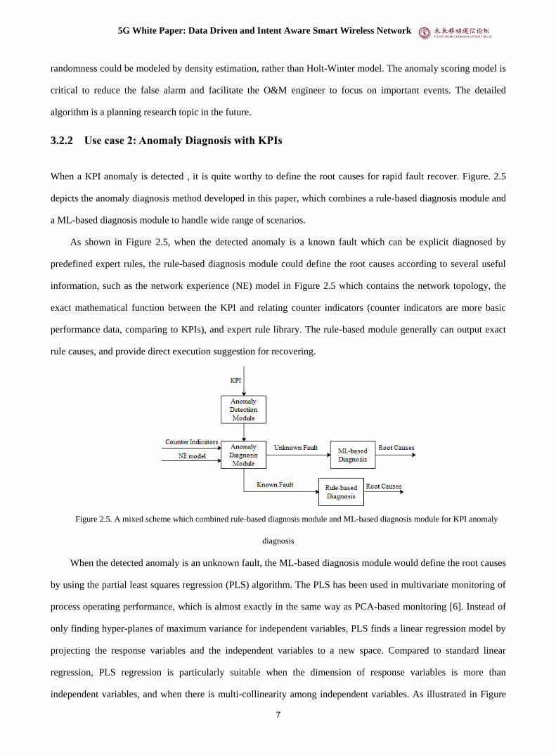
3.2.2 Use case 2: Anomaly Diagnosis with KPIs
When a KPI anomaly is detected , it is quite worthy to define the root causes for rapid fault recover. Figure. 2.5
depicts the anomaly diagnosis method developed in this paper, which combines a rule-based diagnosis module and
a ML-based diagnosis module to handle wide range of scenarios.
As shown in Figure 2.5, when the detected anomaly is a known fault which can be explicit diagnosed by
predefined expert rules, the rule-based diagnosis module could define the root causes according to several useful
information, such as the network experience (NE) model in Figure 2.5 which contains the network topology, the
exact mathematical function between the KPI and relating counter indicators (counter indicators are more basic
performance data, comparing to KPIs), and expert rule library. The rule-based module generally can output exact
rule causes, and provide direct execution suggestion for recovering.
Figure 2.5. A mixed scheme which combined rule-based diagnosis module and ML-based diagnosis module for KPI anomaly
diagnosis
When the detected anomaly is an unknown fault, the ML-based diagnosis module would define the root causes
by using the partial least squares regression (PLS) algorithm. The PLS has been used in multivariate monitoring of
process operating performance, which is almost exactly in the same way as PCA-based monitoring [6]. Instead of
only finding hyper-planes of maximum variance for independent variables, PLS finds a linear regression model by
projecting the response variables and the independent variables to a new space. Compared to standard linear
regression, PLS regression is particularly suitable when the dimension of response variables is more than
independent variables, and when there is multi-collinearity among independent variables. As illustrated in Figure

5G White Paper: Data Driven and Intent Aware Smart Wireless Network
8
2.6, when a KPI is detected abnormal, PLS models the KPI as a response variable and the correlate counter
indicators as independent variables. Following the PLS modelling, the contribution analysis was conducted to find
the top root counter indicators.
Figure 2.6. Root cause analysis with PLS model when a KPI is abnormal.
Denoting the data matrix of correlate counter indicators as X and the matrix of a KPI as Y , the PLS model
between X and Y can be formulated as:
FUQY
ETPX
T
T
+=
+= ,
where T and U are projections of X (the X score, component or factor matrix) and projections of Y (the Y
scores), respectively; P and Q are orthogonal loading matrices; and matrices E and F are the error terms. As the
PLS model has only one response KPI, the PLS1 algorithm can be used for estimating the T, U, P and Q. And then,
a 2T statistics is used to represent the model status at each observation x as:
22x=T ,
where 1/21 )(R TR−= , TT
n
T
1
1
−= and R is the rotation matrix for X. The contribution of i-th
independent variable, i.e. counter indicator, to the 2T statistics is calculated as:
22 ),( xiiTC = ,
where i is the i-th row of . The total contribution of i-th counter indicator to the variation of the KPI can
be calculated as the sum of ),( 2 iTC from n observations. The contributions of all counter indicators are sorted,
and the top-n counter indicators are output as the root causes for the anomaly KPI. Figure 2.7 shows an
experimental example, illustrating the contributions of 60 counter indicators to a anomaly KPI, DL IP Throughput.
The O&M expert confirms that the top counter indicator, DL Used CCE Average Number, is useful for the
anomaly diagnosis, demonstrating the effectiveness of the proposed algorithm.

5G White Paper: Data Driven and Intent Aware Smart Wireless Network
9
Figure 2.7. An experimental example of PLS method for root cause analysis
3.2.3 Use case 3: Smart Carrier Licence Resource Scheduling
Operators are facing challenge of increasing of user data traffic. However, increasing network capacity through
infrastructure investment is not an economical way. Considerng the tiding effect of the network traffic, carrier
license scheduling is considered as a critical solution in situations where infrastructure investment is limited.
However, the existing method strongly relies on the experience of network maintenance staff, and an automatic and
efficient method is needed to help implement carrier license scheduling by predicting network traffic. AI/ML
algorithm can been used for the network traffic prediction. In this section, a Smart Carrier License Resource
Scheduling (SCLRS) is introduced, which is based on the AI/ML considering the spatio-temporal distribution
characteristics of network traffic.
a) Overall architecture of SCLRS
Based on the network optimization platform in the current network, we design SCLRS architecture as shown in
Figure 2.8. In Figure 2.8, the data collector will collect data from RAN. The data customization center in the
network optimization platform can customize the required data (KPI, KQI, and so on) for different applications. For

5G White Paper: Data Driven and Intent Aware Smart Wireless Network
10
the SCLRS, data customization center will receive KPI data related to carrier licence scheduling, as the data list has
been sent from data customization center to the data collection service. Data customization center send KPI data to
carrier licence scheduling strategy generation center, which will predict the trend of carrier expansion. Then,
according to the prediction result, the strategy execution center designs a strategy for carrier licence scheduling,
and the command module will send a carrier license scheduling command based on this strategy. Finally, OMC will
enforce the carrier license scheduling towards the RAN.
OMC
Network optimization platform
collect data
Send carrier license scheduling
command
Monitoring and visualization unit
Data collector
eNB
eNBeNB
RAN
Data
customization
centerCommand Module
Strategy
execution
center
Carrier licsence
scheduling
strategy
generation center
Figure 2.8 overall architecture
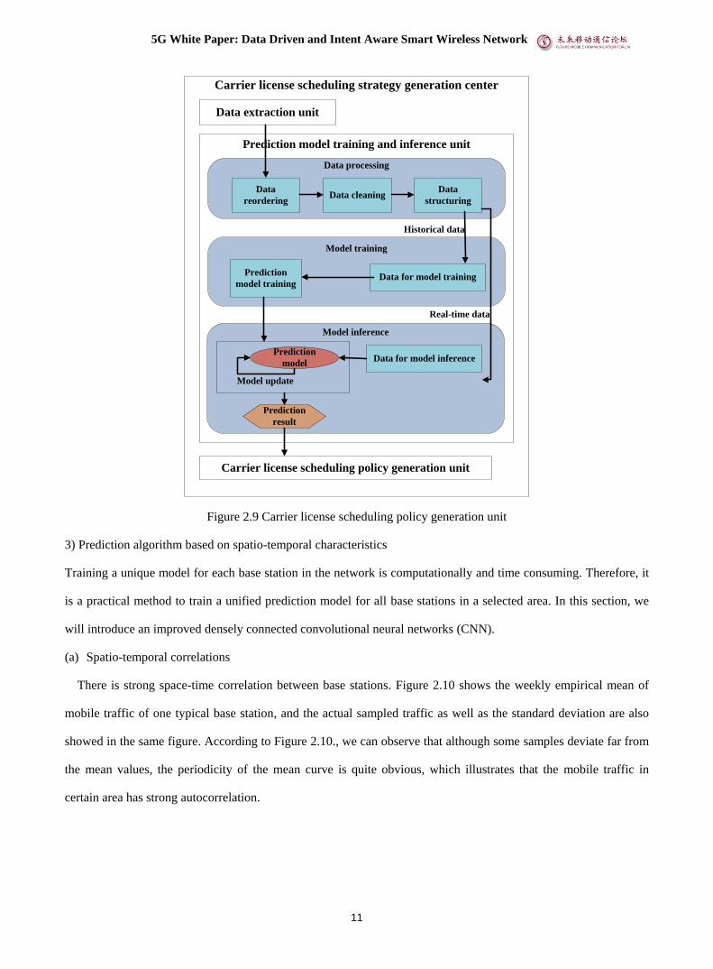
2) Implementation of prediction algorithm based on AI
The carrier expansion prediction based on AI/ML can been realized in carrier license scheduling strategy
generation center, which includes the following parts shown in Figure 2.9: data extraction unit, prediction model
training and inference unit, and carrier license scheduling policy generation unit. Data extraction unit further
extracts KPI data according to the required data format, such as time collection interval, granularity, index list, and
so on. Then, in the prediction model training and inference unit, the extracted data is further processed, such as data
reordering, data cleaning, and data structuring. Following the data processing is the model training (model update)
and model inference. By the trained prediction model, we can predict the future value of the KPIs. And then, carrier
license scheduling policy generation unit formulates scheduling strategies based on the predicted results and the
existing algorithms of the network optimization platform.
5G White Paper: Data Driven and Intent Aware Smart Wireless Network
11
Data processing
Model training
Model inference
Data extraction unit
Data cleaningData
structuring
Prediction
model training
Data
reordering
Data for model training
Data for model inference
Carrier license scheduling policy generation unit
Prediction model training and inference unit
Prediction
result
Carrier license scheduling strategy generation center
Prediction
model
Real-time data
Historical data
Model update
Figure 2.9 Carrier license scheduling policy generation unit
3) Prediction algorithm based on spatio-temporal characteristics
Training a unique model for each base station in the network is computationally and time consuming. Therefore, it
is a practical method to train a unified prediction model for all base stations in a selected area. In this section, we
will introduce an improved densely connected convolutional neural networks (CNN).
(a) Spatio-temporal correlations
There is strong space-time correlation between base stations. Figure 2.10 shows the weekly empirical mean of
mobile traffic of one typical base station, and the actual sampled traffic as well as the standard deviation are also
showed in the same figure. According to Figure 2.10., we can observe that although some samples deviate far from
the mean values, the periodicity of the mean curve is quite obvious, which illustrates that the mobile traffic in
certain area has strong autocorrelation.

5G White Paper: Data Driven and Intent Aware Smart Wireless Network
12
Figure 2.10. Traffic volume sampled over 13 weeks, weekly empirical mean, andstandard deviation in one base station.
Table. 2.1 shows the Pearson correlation coefficients of five representative base stations. It can be seen that good
spatial cross-correlation exists between the BSs.
Table 2.1 Pearson correlation coefficients among representative base stations.
BS. 1 BS. 2 BS. 3 BS. 4 BS. 5
BS. 1 1.0000 0.3387 0.2963 0.3618 0.3524
BS. 2 0.3254 1.0000 0.3579 0.6303 0.6272
BS. 3 0.2263 0.3247 1.0000 0.4060 0.4273
BS. 4 0.4222 0.4783 0.3966 1.0000 0.6952
BS. 5 0.4065 0.5329 0.4200 0.6495 1.0000
In summary,there exists important spatio-temporal correlations among traffic patterns of base stations.
Consequently, both spatial and temporal features can be utilized to improve the precision of prediction when
designing prediction models.
(2) Grid image modeling method
In consideration of the difficulties of determining the specific coverage of base stations, we use smaller grids to
estimate base stations coverage. As for the base stations distributed in areas, we use longitude and latitude to divide
the selected area into a two-dimensional grid image. Figure 2.11 illustrates the griding process and how to map the
traffic data to the neural network tensors.
5G White Paper: Data Driven and Intent Aware Smart Wireless Network
13
(a) Base station distribution in selected area. (b) Distributed area griding. (c) Spatio-temporal multiple input data.
Figure 2.11 Geographical region griding process.
The input data is grouped into closeness dependence data and period dependence data. Different groups of the input
data can be defined as:
• Closeness dependence data: the flow grid images of the previous p hours.
• Period dependence data: the flow grid images of the corresponding time of the past q days.
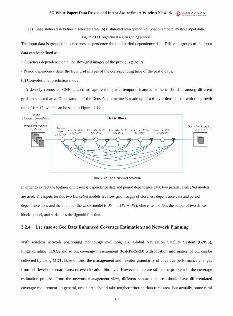
(3) Convolutional prediction model
A densely connected CNN is used to capture the spatial-temporal features of the traffic data among different
grids in selected area. One example of the DenseNet structure is made up of a 6-layer dense block with the growth
rate of k = 12, which can be seen in Figure. 2.12.
Figure 2.12 The DenseNet Structure.
In order to extract the features of closeness dependence data and period dependence data, two parallel DenseNet models
are used. The inputs for this two DenseNet models are flow grid images of closeness dependence data and period
dependence data, and the output of the whole model is 𝑋𝑜 = 𝜎(𝑋𝑐 + 𝑋𝑝), where Xc and Xp is the output of two dense
blocks model, and σ denotes the sigmoid function.
3.2.4 Use case 4: Geo Data Enhanced Coverage Estimation and Network Planning
With wireless network positioning technology evolution, e.g. Global Navigation Satellite System (GNSS),
Finger-printing, TDOA and so on, coverage measurement (RSRP/RSRQ) with location information of UE can be
collected by using MDT. Base on this, the management and monitor granularity of coverage performance changes
from cell level to scenario area or even location bin level. However there are still some problem in the coverage
estimation process. From the network management view, different scenario or area should have differentiated
coverage requirement. In general, urban area should take tougher criterion than rural area. But actually, some rural

5G White Paper: Data Driven and Intent Aware Smart Wireless Network
14
areas with high population density and developed economy do exist. Operators need distinguish scenarios’ trait
more precisely to achieve the target of refined management and planning. And from the trouble shooting view,
coverage hole will be false detected by misleading of no man’s land or MDT data insufficient. For instance, the
scenario of scenic spot in the mountain, users’ measurement only appears at the walkway areas. The coverage
estimation should focus on the walkway rather than the whole spot area.
To achieve more precise coverage estimation, one approach is adding geography information to network
management platform (planning platform, optimization platform, performance monitor platform and etc.). And
based on the Satellite Imagery Semantic Segmentation technology, the operator can collect geography information
from online satellite image at low cost and time-efficient (high resolution image is not necessary). It can recognize
the populated area boundary precisely by analyzing the density of buildings, to assist to set the proper planning KPI
requirement of different areas. Moreover it will detect every location bins’ landforms (water area, mountainous
region, farmland, buildings, roads etc.), than make a Geo-fencing for further scenario-based coverage analysis.
These information combined with MDT measurement could be helpful to correct the coverage rate estimation and
refined network optimization into scenario and bin level.
3.3 MEC Optimization
3.3.1 Use case 5: Intelligent MEC Caching Optimization
(1) Description
Mobile data traffic is anticipated to increase at a 47% compound annual growth rate (CAGR) from 2016 to 2021.
This is largely due to a tremendous growth in not only the number of mobile devices, but also the user interest
towards diverse applications with different characteristics, and demand for large-scale, flexible interconnection of
users and devices. Nevertheless, supporting such a requirement turns to be a big challenge and needs for developing
new architectures. To this end, edge-caching is introduced as one of the promising technologies.
Edge-caching supplements cloud network by deploying Multi-access Edge Computing (MEC) servers with
caching functions in close proximity to the end mobile users. Typically, MEC servers are deployed at the base
stations (BSs) of a wireless network (e.g., a cellular network) for executing delay sensitive and context-aware
applications. Upon receiving demand from users, MEC server directly brings the requested content stored locally to
the users, instead of downloading the content through the backhaul links and then delivering the content to the users.
Therefore, by serving the mobile users locally, edge-caching can alleviate the load on cloud data centers and reduce

5G White Paper: Data Driven and Intent Aware Smart Wireless Network
15
the network delay, and thus improve quality of experience (QoE) of the mobile users. However, due to the random
content request and limited cache memory, the performance of edge-caching network is mainly dominated by two
mechanisms, namely, user behavior prediction and caching policy, which will be investigated in the follows,
respectively.
(2) Solutions
A. User Behavior Prediction
In the context of edge-caching network design, the user behavior prediction is to make prediction about the
possible content request in future for target mobile end user(s). The existing works on user behavior prediction
problem can be studied from the following four aspects:
• The dimension(s) of considered data has impact on the prediction design. The prediction of content
popularity or user preference can be based on single-domain data, e.g., the data from Youtube. On the
other hand, the prediction can be based on the data from several related domains, namely cross-domain
prediction. As an example, the preference of an individual user is determined by not only previous
requesting history for contents, but also the user’s social ties.
• As per prior knowledge of content popularity, the prediction problem can be categories in two
approaches: model-based and model-free. Model based prediction: the content requests are generated by a
parametric. Model free prediction: there is no assumption on the content request distribution.
• In the case of optimization target, the prediction problem can be classified into: content popularity and
user preference. The content popularity corresponds to overall performance of the network, i.e.., it focuses
on how many hits from all users in the network. Comparatively speaking, the user preference is related to
performance of individual user(s), i.e., it focuses on how many hits from an individual user or a certain
small user group with similar preference.
• In the case of optimization method, a broad family of machine learning algorithms have been studied, due
to their efficiency on solving prediction problems. The learning algorithms can be further categorized into
stochastic learning optimization and deterministic learning optimization.
B. Caching Policy
Based on the user behavior prediction results, caching policy can be designed. There are three categories of
caching policies, namely, proactively caching policy, reactively caching policy, and static caching policy. The
proactively caching policy pushes content files before they are requested by the user. The reactively caching policy
transmit content files to the user when they are requested, and then the files can be cached locally so that they can

5G White Paper: Data Driven and Intent Aware Smart Wireless Network
16
be read locally if being requested again. The static caching policy is obtained by solving some deterministic
optimization problem. It determines the files to be cached deterministically and do not change them until the
system state changes.
A taxonomy for edge-caching network design can be considered for the intelligent MEC optimization. This
taxonomy provides a framework for comparative study of the existing works and hints at the development of new
user behavior prediction algorithms and caching policy. Furthermore, this taxonomy helps to analyze the
edge-caching network status and requirements as well as select appropriate model and method for design, and thus
facilitate the intelligent management and operation of the edge-caching networks.
3.4 Network Resource Optimization
3.4.1 Use case 6: AI Empowered QoE Optimization
Mobile communication system uses QoS framework to support different QoS requirements of different traffic, the
related QoS parameters are provided to the base station for radio resource allocation. QoE e.g. a MOS value is
measured at application layer based on application layer info to estimate the level of user experience. However, the
QoE is unknown in the mobile communication system. This means when the base station adjusts the radio resource
allocation for each user and the application traffic, it doesn’t have a direct estimation whether the adjustment will
be positive or negative to the user experience. This may incur the complaint from user or application service
provider later or may introduce more signaling interaction to adjust the radio resource back and forth in the
communication system. So it’s important for the network to estimate or predict the user experience based on
network side information and optimize the radio resource based on the real-time QoE prediction. Multi-dimensional
data, e.g. user traffic data, network measurement report, application layer MOS value, can be acquired and used for
offline ML model training of a QoE estimation model. The model inference will be executed in a real-time manner
in the mobile communication system to estimate or predict the user experience based on network side information.
Thus the base station could adjust the radio resource allocation more efficiently and more accurately based on the
estimation or prediction of user experience.
Moreover, the available radio bandwidth prediction can also help the application layer to dynamically adapt its
codec rate or the transport layer for the TCP optimization. In this scenario, the predicted available radio bandwidth
is expected to be opened from the radio access network to facilitate the optimization.
To support the AI powered QoE optimization, the following AI/ML models are expected:

5G White Paper: Data Driven and Intent Aware Smart Wireless Network
17
(1) Application classification: this model is used to identify the desired applications to be optimized. For example,
with the user plane traffic data, the cloud VR application is supposed to be identified so that specific
optimization can be applied to assure the desired QoE performance.
(2) KQI/QoE prediction model: this model is to predict the KQI or QoE of the specific application after the
application is well identified. The model is expected to use both the application level and network level data,
e..g., application codec rate/bit rate, UE level radio channel information, mobility related metrics, L2
measurement report related to traffic pattern, e.g., throughput, latency, packets per-second, inter frame arrival
time, PDCP buffer status, cell level DL/UL PRB occupation rate;
(3) Available radio bandwidth prediction model: this model is to predict the available radio bandwidth. The
network channel condition data, e.g., transport block size, channel quality indicator (CQI), MCS, are required
for training and inference of the model.
3.4.2 Use case 7: Smart Resource Management for Network Slicing
(1) Description
The emerging fifth-generation (5G) mobile systems, armed with novel network architecture and emerging
technologies, are expected to offer support for a plethora of network services with diverse performance
requirements. The concept of network slicing has been recently proposed, where the physical and computational
resources of the network can be sliced to meet the diverse needs.
To provide better-performing and cost-efficient services, RAN slicing involves more challenging technical
issues for the realtime resource management on existing slices, since (a) for radio access networks, spectrum is a
scarce resource and it is essential to guarantee the spectrum efficiency (SE); (b) the service level agreements (SLAs)
with slice tenants usually impose stringent requirements on quality of experience (QoE) perceived by users; and (c)
the actual demand of each slice heavily depends on the request patterns of mobile users.
The classical dedicated resource allocation fails to simultaneously address these problems. One potential
solution is reinforcement learning (RL). RL is an important type of machine learning where an agent learns how to
perform optimal actions in an environment via observing states and obtaining rewards. Recently, inspired by the
theory of quantile regression, a quantile regression DQN (QR-DQN) and Wasserstein generative adversarial
network with gradient penalty (WGAN-GP) to replace the value of Q(s, a) by a distribution as well as the
reputation of generative adversarial network (GAN) to approximate one distribution, a new algorithm based on
distributional RL and WGAN-GP, namely GAN-powered deep distributional Q network (GAN-DDQN) is

5G White Paper: Data Driven and Intent Aware Smart Wireless Network
18
considered to realize dynamic and efficient spectrum allocation per slice[7].
(2) Solutions
Under the framework of hierarchical network slicing, we consider a radio access network (RAN) scenario with
multiple base stations (BSs) , where there exists a list of available slices 1, 2,⋯ ,M sharing the aggregated
bandwidth W and having fluctuating traffic demands 𝐝 = (𝑑1, 𝑑2, ⋯ 𝑑𝑀). The objective of our work is to find an
optimal bandwidth-sharing solution 𝐰 = (𝑤1, 𝑤2, ⋯𝑤𝑀) which maximizes the expectation of the whole system
utility, which is defined as the weighted sum of SE and QoE satisfaction ratio (i.e., α ∙ SE + β ∙ QoE). Notably,
the time-varying demand at one slot depends on both the demand at previous slot and the related allocated
bandwidth, since the maximum sending capacity of servers belonging to one service is tangled with the
provisioning capabilities for this service. For example, the TCP sending window size is influenced by the estimated
channel throughput. Therefore, the traffic demand varies without knowing a prior transition probability, making the
optimization difficult to yield a direct solution. However, RL promises to be applicable to tackle with this kind of
problem. Therefore, we refer to RL to find the optimal policy for network slicing and build the system model as
illustrated in Figure 2.13. In particular, we map the RAN scenario to the context of RL by taking the number of
arrived packets in each slice within a specific time window as the state, and the allocated bandwidth to each slice as
the action.

5G White Paper: Data Driven and Intent Aware Smart Wireless Network
19
Figure 2.13 An illustration of GAN-DDQN for resource management in network slicing.
WGAN-GP is introduced to estimate the
distribution of action values by minimizing the distance between the estimated action-value distribution and the
distribution calculated by the Bellman optimality operator. As for the updating and training procedure, the agent
first randomly selects $m$ transitions from the replay buffer as a minibatch for training GAN-DDQN. Then, the
agent executes the Bellman optimality operator on each transition of the selected minibatch and obtains a set of
samples that describe the real distribution. Finally, we use the designed loss functions to train the generator and
descriminator networks.
(3) Performance evaluations
Table 2.2 A brief summary of key settings for traffic generation per slice

5G White Paper: Data Driven and Intent Aware Smart Wireless Network
20
In this part, we verify the performance of GAN-DDQN in a RAN scenario where there are three types of
services (i.e., VoLTE, video, and URLLC) and three corresponding slices in one single BS.
With the mapping as shown in Table 2.3, RL algorithms can be used to optimize the system utility (i.e., the
weighted sum of system SE and slice QoE). Specifically, we perform round-robin scheduling within each slice at
the granularity of 0.5 ms. In other words, we sequentially allocate the bandwidth of each slice to the active users
within each slice every 0.5 ms. Besides, we adjust the bandwidth allocation to each slice per second. Therefore, the
agent updates its neural networks every second. We primarily consider the downlink case and adopt system SE and
QoE satisfaction ratio as the evaluation metrics. In particular, the system SE is computed as the number of bits
transmitted per second per unit bandwidth, in which the rate from the BS to mobile users is derived based on
Shannon capacity formula. Therefore, if part of the available bandwidth has been allocated to one slice but the slice
has no service activities at that slot, such part of bandwidth would have been wasted, thus degrading the system
SE. QoE satisfaction ratio is obtained by dividing the number of completely transmitted packets satisfying rate and
latency requirement by the total number of arrived packets.
Table 2.3 The mapping from resource management for network slicing to RL environment

5G White Paper: Data Driven and Intent Aware Smart Wireless Network
21
Figure 2.14 An illustration of the performance comparison between different slicing schemes (GAN-DDQN, DQN,
and hard slicing).
In this part, we compare the simulation results of the proposed GAN-DDQN algorithm with other DQN-based
allocation scheme and hard slicing method. The DQN-based allocation scheme is proposed in [8], which directly
applies the original DQN algorithm to network slicing scenario. Hard slicing means that each service is always
allocated with 1/3 of the whole bandwidth, since there exist 3 types of service in total. Again, round-robin is
conducted within each slice. Figure 2.14 depicts the variations of the system utility with respect to the episode
index considering three different networ of α and β,It can be observed from Figure 2.14 that the system utility
obtained by the GAN-DDQN algorithm is significantly higher than that of the DQN algorithm and hard slicing in
the cases of α = 0.1, β = [1; 1; 1] and α = 0.01, β = [1; 1; 1] . This is due to the fact that the proposed
GAN-DDQN algorithm is built on the distributional RL, which enhances its ability to learn an optimal allocation
policy from the dynamic and unstable networking environment.

5G White Paper: Data Driven and Intent Aware Smart Wireless Network
22
Figure 2.15 An illustration of the SE and QoE satisfaction ratio in the different cases of α = 0.1, β = [1; 1; 1]
(shown in the top figures), α = 0.01, β = [1; 1; 1] (shown in the middle figures) and α = 0.1, β = [1; 1; 10]
(shown in the bottom figures).
Figure 2.15 presents the variations of the SE and QoE satisfaction ratio with respect to the episode index in the
different cases. It can be observed from Figure 2.15 that the QoE satisfaction ratios for both VoLTE and video
services achieve 100% along with the iterative training. However, GAN-DDQN and DQN algorithms perform
differently on the system SE and the QoE of URLLC service.
In a word, neither GAN-DDQN nor DQN can guarantee that both SE and QoE achieve a high degree at the same
time, which is due to the reason that it is still a very challenging research topic to design RL with multiple
conflicting rewarding metrics. The simulation results have demonstrated that we cannot guarantee to
simultaneously obtain superior performance for both SE and QoE. This inspiring and interesting topic still needs
future investigation.
3.4.3 Use case 8: Data Driven Predictive Resource Allocation
(1) Description
Predictive resource allocation (PRA) is a promising way to harness wireless big data by predicting user
behavior related information such as user mobility and traffic load with machine learning. It can improve network

5G White Paper: Data Driven and Intent Aware Smart Wireless Network
23
throughput, reduce energy consumption, and enhance user quality of service (QoS) remarkably for non-real-time
(NRT) services (such as file download and video transmission), which has been shown able to provide large gain
over non-predictive counterparts.
To achieve the large gain of PRA, the behavior-related information needs to be predicted, say user trajectory,
traffic load, average channel gains or data rates, which change in different timescales since the dynamics are
induced by different mechanisms. Despite that various behavior-related information has been predicted in the
literature, they are targeted to diverse applications such as location-based service and autonomous driving. As a
result, existing prediction methods either provide coarse-grained prediction over long horizon (e.g., one day) with
data of low sampling resolution (e.g., with sampling period of 15 minutes or even a hour), or support fine-grained
prediction over short horizon (e.g., few seconds) with data of high resolution (e.g., with sampling period of 10~100
milliseconds). Such long or short prediction horizon is useless for PRA, and recording fine-grained data in cellular
network needs huge storage capacity. Furthermore, it is well-known that prediction accuracy deteriorates quickly as
the prediction horizon increases. Yet few priori works have addressed if the required information is predictable
over the minute-level horizon, and how the required information for predictive resource allocation is predicted. In
[9], a hierarchical PRA scheme for NRT service was proposed, which only requires coarse-grained prediction. With
such a scheme, high throughput can be supported by predicting the required information with heterogeneous data
with low-resolution, and with much less training samples than the existing scheme. Considering that machine
learning is a powerful tool to predict user behavior and harness the vast amount of data measured in cellular
networks, the study in [9] further investigated if the required knowledge for making the decision can has coarse
temporal-spatial resolution and can be predicted from raw data in low resolution without any translation. A deep
neural network (DNN) was designed to learn the future information required for making decision directly from
different types of past data with different resolution observable in cellular networks. The results show that the
proposed scheme with the end-to-end (E2E) prediction performs closely to the relevant optimal solution with
perfect prediction, and provides dramatic gain over non-predictive counterpart in supporting high request arrival
rate for NRT service. To avoid offline training and allow online learning, deep reinforcement learning policy was
proposed in [10] for PRA, by taking energy efficiency as an example objective.
In interference networks, PRA also provides huge performance gain. Intuitively, interference can be controlled
more flexibly by leveraging future average channel gains to improve QoS of mobile users with delay tolerant
service, since the interference can be coordinated in a much larger time-space range. However, optimizing the
resource allocation in a predictive manner for interference networks is challenging, since how to allocate future

5G White Paper: Data Driven and Intent Aware Smart Wireless Network
24
resources depends on the future signal to interference plus-noise ratio (SINR), and the SINR relies on the assigned
resources. As a result, most existing works for PRA ignore inter-cell interference (ICI) or simply treating ICI as
noise, which limits the user experience and network performance in densely-deployed cellular networks. In [11], a
policy of PRA with ICI coordination (PRA-ICIC) was proposed, which employs the future average channel gains
of each user in a prediction window to coordinate ICI by muting base stations (BSs) and optimizing user
association. However, finding the optimal solution of PRA-ICIC incurs prohibitive computational complexity,
which is unaffordable for a longer prediction window. To reduce the complexity of real-time processing for
optimizing transceivers, a DNN was developed in [12] to learn the optimal policy for heterogeneous networks. The
DNN can learn from the historical data in an end-to-end manner. Simulation results show that the proposed
DNN-based solution performs closely to the numerically-obtained optimal solution with much lower computational
complexity.
(2) Solutions
a) Coarse-grained PRA with E2E prediction
In [9], it shows that PRA with minute- and cell-level knowledge prediction is able to achieve negligible
performance loss from the optimal solution with perfect future rate in each frame of a prediction window. A
multi-input-multi-output orthogonal frequency multi-access (MIMO-OFDMA) was taken as an example system
and throughput as an example performance metric. A threshold-based scheme was proposed to achieve high
throughput while satisfying the QoS for the MSs requesting video-on-demand (VoD) service, based on the idea
proposed in [14]. The principle behind PRA for serving NRT users is to transmit more data to a MS when the MS
moves to a location with high average data rate, whose average rate depends on its average channel gain and the
traffic load in its located cell. In order to improve the performance of network with guaranteed QoS for the MS,
such a principle can be interpreted as finding two thresholds. To support high throughput, the BSs should transmit
more bits to a MS with good channel condition. Hence, a threshold is necessary to determine whether or not the
average channel gain at a location is good. To reduce stalling time in video streaming, more segments should be
transmitted by a BS with light traffic load to a MS heading to heavily loaded cells. Hence, another threshold is
required to determine whether or not the residual resource in a cell is sufficient for causing less stalling. With the
two thresholds, a BS can judge if a MS can be served with higher average rate. Such a scheme allows the decision
of resource management to be made in a central processor (CP) and the BSs in different timescales, and allows the
knowledge to be predicted with less training samples.

5G White Paper: Data Driven and Intent Aware Smart Wireless Network
25
To implement such a threshold-based PRA, the CP needs to first predict the information based on historical
data in the observation window. Then, the CP translates the predicted information to the required knowledge for
making decision. For example, the CP first predicts trajectory and then translates it into future average gains with
the radio map and finally computes the threshold. The whole procedure to obtain the finally predicted knowledge is
rather complicated in this way. Inspired by the ability of DNN in learning the hidden features of the inputs and in
deducing complicated relation between different information, a DNN was designed in [9] to predict the required
knowledge for decision making in an E2E manner, where the procedure of predicting the required knowledge only
consists of a single learning step, without the need for multi-stage learning pipelines and the information
translation.
The designed DNN is shown in Figure 2.16, which contains four sub-DNNs to predict different information.
Each sub-DNN is a fully connected (FC) DNN, which contains L layers. The input of the DNN is the historical data,
and the output is the predicted two thresholds as well as the service BS set. Sub-DNN-1 is used to predict the
service BS set, i.e., the BSs that the typical MS (say MSk ) will successively associate with, which depends on the
trajectory of the MS. The location of the MS can be implicitly inferred at the CP with the average channel gains of
the MS from several adjacent BSs and the known locations of the BSs. Therefore, the input of sub-DNN-1 is the
number of records for the past average channel gains. The output is the cells that each MS will associate with in the
prediction window. Sub-DNN-2 is used to predict the threshold for average channel gains. Since the threshold
depends on user’s trajectory, the input is the same as that in Sub-DNN-1. Sub-DNN-3 is used to predict the average
residual bandwidth of the typical BS, which depends on the resource occupied by the RT service. Therefore, the
input is the number of records of RT traffic load. Sub-DNN-4 is used to predict the threshold for residual
bandwidth, which is related to the past VoD requests and past sojourn time of the MSs. The input is the numbers of
records of VoD requests and sojourn time.

5G White Paper: Data Driven and Intent Aware Smart Wireless Network
26
Figure 2.16 Structure of the designed DNN for the end-to-end prediction.
Figure 2.17. Observation window and Prediction window.
As shown in Figure 2.17, the input of the DNN is from the collected historical data records in the observation
window, and the output is the predicted knowledge. The sub-DNNs can predict different knowledge from different
types of record in the prediction window.
b) PRA-ICIC with E2E prediction
The study in [10] investigated predictive resource allocation for mobile users requesting NRT service in
HetNets with ICI. To coordinate interference, a BS muting is allowed when the BS generating strong ICI. To deal
with the “chicken-and-egg” challenge, the resource allocation plan is designed in two steps at the start of a
prediction window, when future average channel gains are available. A predictive interference coordination scheme
is optimized to find which BSs can transmit to which users concurrently that ensures a given average SINR. Then, a

5G White Paper: Data Driven and Intent Aware Smart Wireless Network
27
common resource allocation plan is optimized for this group of BS-user pairs that maximizes a network utility
aiming to improve user satisfactory rate. Since the common plan is made for a group of users that request files with
different sizes and are with different average SINRs, it is non-trivial to satisfy the QoS for all these users
meanwhile not to waste radio resources. To deal with the difficulty in making a single plan for multiple users, a
logistic function is introduced to characterize the network utility that can make more users satisfied without wasting
radio resources. By resorting to graph theory, we obtain the optimal interference coordination scheme and the
optimal resource allocation plan. Simulation results showed remarkable performance gain over the non-predictive
ICI-coordination or predictive resource allocation designed by assuming ICI as noise.
To reduce the complexity of real-time processing for optimizing transceivers in wireless systems, an
off-line-trained DNN was introduced to approximate the relation between the optimized transceiver and channel
gains [11,12]. Such an approach was employed in [12] to learn the optimal PRA policy, where the on-line
complexity is reduced to about 1% of the traditional numerical optimization algorithm (i.e., interior point method).
To design a DNN to learn the PRA-ICIC policy in [10], the study in [11] finds that in this problem there exists data
bias issue, where the optimal solution contains much more “0” than “1”. When such solutions are used as the labels
for supervised learning, the trained DNN cannot learn the optimal policy very well. To circumvent this problem,
the DNN was designed to learn whether each user is served in each frame of the prediction window rather than
learn the optimal policy directly. Then, a user association algorithm was designed to determine which BSs transmit
signals to which users in each frame.
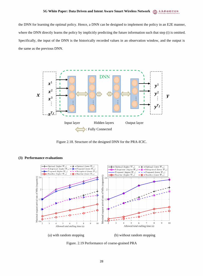
As shown in Figure 2.18, the DNN is aimed to learn whether or not the UEs are served in each frame, which is
designed as a FC-DNN. In the interference networks, each UE is interfered by other BSs when they are serving
other UEs, which affects resource allocation. Consequently, the input of the DNN should contain the information of
all BSs and all UEs within the prediction window. In particular, the input should contain two types of known
parameters used in the PRA-ICIC policy. The first type is the maximal average receive power of all MSs from all
BSs within the prediction window, the second type is the normalized data amount of all MSs from all BSs. The
expected output is whether each MS is served in each frame of the prediction window.
The PRA-ICIC policy is implemented by three steps, where the CP operates in the following three steps. (i)
Predicts the maximal average receive power and normalized data amount in the prediction window with the
historically recorded values in the observation window. (ii) Learn an intermediate solution of the policy by the
DNN. (iii) Use the association algorithm to obtain the resource allocation plans. In practice, the values of maximal
average receive power and normalized data amount can also be predicted by DNN, which can be incorporated into
5G White Paper: Data Driven and Intent Aware Smart Wireless Network
28
the DNN for learning the optimal policy. Hence, a DNN can be designed to implement the policy in an E2E manner,
where the DNN directly learns the policy by implicitly predicting the future information such that step (i) is omitted.
Specifically, the input of the DNN is the historically recorded values in an observation window, and the output is
the same as the previous DNN.
Figure 2.18. Structure of the designed DNN for the PRA-ICIC.
(3) Performance evaluations
(a) with random stopping (b) without random stopping
Figure. 2.19 Performance of coarse-grained PRA
…
…
DNN
𝒙1
x
𝒚1
…
…
…
: Fully Connected
Input layer Hidden layers Output layer
…
𝒙2
𝒙3
𝒙𝑻𝒇
𝒚2
𝒚𝑻𝒇
y …

5G White Paper: Data Driven and Intent Aware Smart Wireless Network
29
Figure. 2.19 shows the performance of coarse-grained PRA. Figure. 2.19 (a) and (b) respectively illustrate the
simulation results of the supported maximal arrival rate of MSs versus the total stalling time allowed by each MS,
which reflects the ability of each method to support the system throughput. The “optimal method” is the upper
bound of performance that is achieved by solving the optimization problem when the prediction information is
accurate, and the “benchmark method” is the traditional non-predictive method. The simulation is carried out in
two scenarios of high and low network residual resources. Simulation results showed that the proposed scheme
with E2E prediction performs closely to the relevant optimal solution with perfect prediction, and provides
dramatic gain over non-predictive counterpart in supporting high request arrival rate for the NRT service. The gain
grows with the required duration of the prediction window.
(a) T = 5 s. (a) T = 30 s.
Figure. 2.20 Performance of PRA-ICIC
Figure. 2.20 shows the performance of PRA-ICIC. Compared with the non-PPA with ICIC and PRA without
ICIC, the PRA-ICIC outperforms the reference strategies for different values of B and K. It provides much higher
user satisfactory rate than existing PRA policies when the traffic load is high and outperforms non-predictive
resource allocation remarkably when the prediction window is long.
The “DNN-non-E2E” is the DNN trained in a non-E2E manner, where the input is the predicted information
in the prediction window and the “DNN-E2E” is the DNN trained in the E2E manner, where the input is the
historical information in the observation window. Simulation results showed that the proposed DNN with E2E
learning performs closely to the optimal policy, but only with 6‰ of the computational time of the original
problem.

5G White Paper: Data Driven and Intent Aware Smart Wireless Network
30
3.4.4 Use case 9: Big Data Analysis for Handover Optimization in Massive-MIMO Cellular
Systems
(1) Description
The application of massive multiple-input multiple-output (MIMO) technology, relying on a large number of
antennas and transceivers, is able to greatly increase system capacity, extend cell coverage and reduce interference
level. One of the key issues in massive-MIMO is the beam selection for each served user equipment (UE),
especially in the handover procedure in the cellular networks. The handover success rate and interruption time are
dependent on the target beam selection effect and speed. In general, the target base station has no a priori
hypothesis about the channel information of the incoming UE until UE sending measurement report or wait for UE
sending SRS and then calculate the beam that fits to uplink and downlink by channel reciprocity. Both of these two
approaches would cause significant handover delay and service interruption in the scale of milliseconds or longer.
A self-optimization network (SON)-type approach, named as enhanced automatic neighbor relation (eANR)
function, was adopted to solve this issue, which extends the traditional neighbor cell relation (NCR) table in ANR
function with massive MIMO information by dynamic updating the suitable beam pairing relations between source
cell and target cell. Based on it, when a UE is about to perform handover, the suitable target-cell beam can be
derived by simply looking up beam-specific NCR table with the source-cell beam as index, without taking time in
field measurement on the radio channel of target cells, and hence the handover process in massive-MIMO cellular
systems can be accelerated. We further develops such SON-type approach employing the big data analysis on beam
spectrum storages to replace the pairing table of one-to-one source-target beams in the issue of handover
optimization [15].
(2) Proposed methods
Assuming on each subcarrier, the complete channel response vector ℎ⃗ 𝑘(𝑐)
equals the Kronecher product of the
horizontal vector ℎ⃗ 𝑘(ℎ)
and vertical vector ℎ⃗ 𝑘(𝑣)
,
ℎ⃗ 𝑘(𝑐)
= ℎ⃗ 𝑘(ℎ)
⨂ℎ⃗ 𝑘(𝑣)
, 𝑘 = 0,… , 𝐾 − 1. (1)
When scanning the beam codebook with user channel response vector, we can project these multi-path radio
channel profiles onto the subspace spanned by the beam codeword dimensions, so as to generate a beam spectrum,
denoted as 𝐶 (ℎ) ≜ [𝑐0, 𝑐1, ⋯ 𝑐𝑆ℎ−1] in the horizontal plane or 𝐶 (𝑣) ≜ [𝑐0′ , 𝑐1
′ , ⋯ 𝑐𝑆𝑣−1′ ] in the vertical plane, where
5G White Paper: Data Driven and Intent Aware Smart Wireless Network
31
𝑐𝑥 =1
𝐾∑
|⟨�⃗� 𝑥,ℎ⃗⃗ 𝑘(ℎ)
⟩|
‖�⃗� 𝑥‖2‖ℎ⃗⃗ 𝑘
(ℎ)‖
2
𝐾−1𝑘=0 , 𝑥 = 0,… , 𝑆ℎ − 1, (2)
𝑐𝑦′ =
1
𝐾∑
|⟨�⃗� 𝑦,ℎ⃗⃗ 𝑘(𝑣)
⟩|
‖�⃗� 𝑦‖2‖ℎ⃗⃗
𝑘(𝑣)
‖2
𝐾−1𝑘=0 , 𝑦 = 0,… , 𝑆𝑣 − 1, (3)
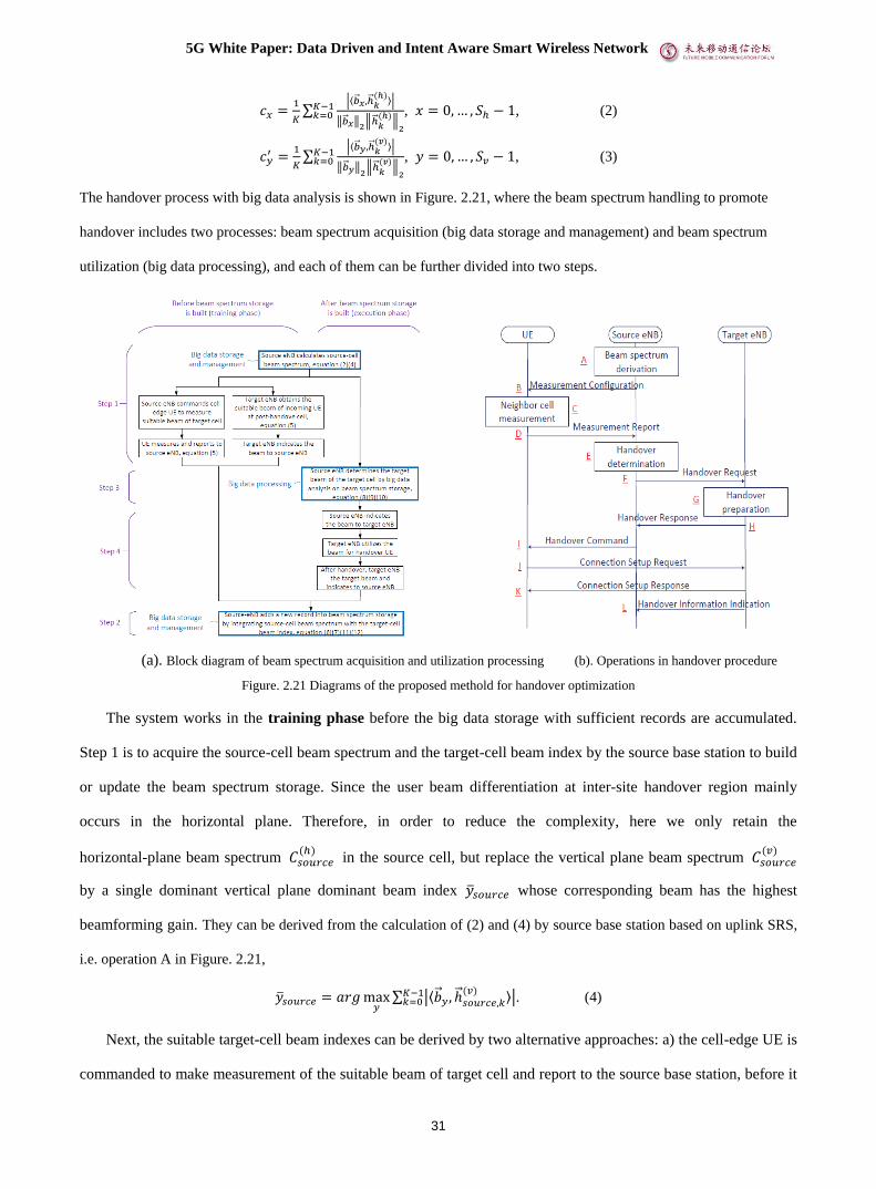
The handover process with big data analysis is shown in Figure. 2.21, where the beam spectrum handling to promote
handover includes two processes: beam spectrum acquisition (big data storage and management) and beam spectrum
utilization (big data processing), and each of them can be further divided into two steps.
(a). Block diagram of beam spectrum acquisition and utilization processing (b). Operations in handover procedure
Figure. 2.21 Diagrams of the proposed methold for handover optimization
The system works in the training phase before the big data storage with sufficient records are accumulated.
Step 1 is to acquire the source-cell beam spectrum and the target-cell beam index by the source base station to build
or update the beam spectrum storage. Since the user beam differentiation at inter-site handover region mainly
occurs in the horizontal plane. Therefore, in order to reduce the complexity, here we only retain the
horizontal-plane beam spectrum 𝐶𝑠𝑜𝑢𝑟𝑐𝑒(ℎ)
in the source cell, but replace the vertical plane beam spectrum 𝐶𝑠𝑜𝑢𝑟𝑐𝑒(𝑣)
by a single dominant vertical plane dominant beam index �̅�𝑠𝑜𝑢𝑟𝑐𝑒 whose corresponding beam has the highest
beamforming gain. They can be derived from the calculation of (2) and (4) by source base station based on uplink SRS,
i.e. operation A in Figure. 2.21,
�̅�𝑠𝑜𝑢𝑟𝑐𝑒 = 𝑎𝑟𝑔 max𝑦
∑ |⟨�⃗� 𝑦, ℎ⃗ 𝑠𝑜𝑢𝑟𝑐𝑒,𝑘(𝑣) ⟩|𝐾−1
𝑘=0 . (4)
Next, the suitable target-cell beam indexes can be derived by two alternative approaches: a) the cell-edge UE is
commanded to make measurement of the suitable beam of target cell and report to the source base station, before it

5G White Paper: Data Driven and Intent Aware Smart Wireless Network
32
performs handover, i.e. operation B-D; b) after the UE completes handover, the target base station acquires the
suitable beam in a regular way and then indicates the target beam to the source base station via inter-base station
message channel (like X2 interface), i.e. operation L. Based on the channel response vector, the suitable target-cell
beam index pair for horizontal plane and vertical plane is determined by calculating its Hermitian inner-product
with candidate beam codeword,
(�̅�𝑡𝑎𝑟𝑔𝑒𝑡 , �̅�𝑡𝑎𝑟𝑔𝑒𝑡) = 𝑎𝑟𝑔max𝑥,𝑦
∑ |⟨�⃗� 𝑥 ⊗ �⃗� 𝑦, ℎ⃗ 𝑡𝑎𝑟𝑔𝑒𝑡,𝑘(𝑐) ⟩|𝐾−1
𝑘=0 . (5)
In Step 2, the instant horizontal-plane beam spectrum and vertical-plane dominant beam index in the source
cell and the suitable horizontal and vertical beam indexes in the target cell, together with the time stamp 𝑇𝑙, are
integrated as a new record ℛ𝑙,
ℛ𝑙 ≜ [𝐶 𝑠𝑜𝑢𝑟𝑐𝑒,𝑙(ℎ)
, �̅�𝑠𝑜𝑢𝑟𝑐𝑒,𝑙 , �̅�𝑡𝑎𝑟𝑔𝑒𝑡,𝑙 , �̅�𝑡𝑎𝑟𝑔𝑒𝑡,𝑙 , 𝑇𝑙], (6)
and then added into the beam spectrum storage.
To reduce the complexity, the big data storage can be managed in the way of dividing into a number of
sub-storage, each of which corresponds to one of the source vertical-plane beam indexes,
𝕊𝑢 ≜ {ℛ𝑙|�̅�𝑠𝑜𝑢𝑟𝑐𝑒,𝑙 = 𝑢}. (7)
The system works in the execution phase after the big-data storage with sufficient records accumulated. In
Step 3, the source base station would determine the suitable target-cell post-handover beam (�̅�𝑡𝑎𝑟𝑔𝑒𝑡, �̅�𝑡𝑎𝑟𝑔𝑒𝑡)
based on the known current horizontal-plane beam spectrum 𝐶 𝑠𝑜𝑢𝑟𝑐𝑒(ℎ)
and vertical-plane dominant beam index
�̅�𝑠𝑜𝑢𝑟𝑐𝑒 in source cell, by big data processing on the beam spectrum records, i.e. operation E. Next, the source base
station indicates the determined target-cell beam to the target base station, i.e. operation F. The source-cell
vertical-plane dominant beam index of current user (denoted as �̅�𝑠𝑜𝑢𝑟𝑐𝑒,0) is used to address a correspondent sub-storage
𝕊�̅�𝑠𝑜𝑢𝑟𝑐𝑒,0. In following, the matching degrees (denoted as 𝑀𝑙) between the source-cell horizontal-plane of the current
user (denoted as 𝐶 𝑠𝑜𝑢𝑟𝑐𝑒,0(ℎ)
) and the stored horizontal-plane beam spectrums of historical users (denoted as 𝐶 𝑠𝑜𝑢𝑟𝑐𝑒,𝑙(ℎ)
) , are
calculated,
𝑀𝑙 ≜|⟨𝐶 𝑠𝑜𝑢𝑟𝑐𝑒,0
(ℎ),𝐶 𝑠𝑜𝑢𝑟𝑐𝑒,𝑙
(ℎ)⟩|
‖𝐶 𝑠𝑜𝑢𝑟𝑐𝑒,0(ℎ)
‖2‖𝐶 𝑠𝑜𝑢𝑟𝑐𝑒,𝑙
(ℎ)‖
2
, ∀𝑙, with ℛ𝑙 ∈ 𝕊�̅�𝑠𝑜𝑢𝑟𝑐𝑒,0. (8)
Second, the target-cell beam index is jointly determined based on 𝑀𝑙 and 𝑇𝑙 of the records. Set a sliding
window to filter out a certain number (denoted as L) of the latest beam spectrums records from the corresponding
sub-storage 𝕊�̅�𝑠𝑜𝑢𝑟𝑐𝑒,0, whose matching degree is not less than a pre-configured threshold 𝛼, 0 < 𝛼 < 1, i.e. the
latest records with �̅�𝑠𝑜𝑢𝑟𝑐𝑒,𝑙 = �̅�𝑠𝑜𝑢𝑟𝑐𝑒,0 and 𝑀𝑙 ≥ 𝛼; Tag a forgetting weight to each record whose value depends

5G White Paper: Data Driven and Intent Aware Smart Wireless Network
33
on the timing gap between the recorded time stamp and the present time stamp, 𝜔𝑙 ≜ 𝛽𝑇0−𝑇𝑙wl , 0 < 𝛽 < 1,
where 𝛽 is a pre-configured forgetting factor. In this way, the matching degree is updated as
𝑀𝑙′ = 𝑀𝑙𝜔𝑙; (9)
Generate the target beam index of the current user (�̅�𝑡𝑎𝑟𝑔𝑒𝑡,0, �̅�𝑡𝑎𝑟𝑔𝑒𝑡,0) from the beam codeword that is the
nearest to the weighted average of filtered records,
(�̅�𝑡𝑎𝑟𝑔𝑒𝑡,0, �̅�𝑡𝑎𝑟𝑔𝑒𝑡,0) = ⌊∑ 𝑀𝑙
′∙(�̅�𝑡𝑎𝑟𝑔𝑒𝑡,𝑙,�̅�𝑡𝑎𝑟𝑔𝑒𝑡,𝑙)𝐿𝑙=1
∑ 𝑀𝑙′𝐿
𝑙=1⌉. (10)
In Step 4, dependent on the indicated beam information, the target base station can prepare a dedicated
transmitting or receiving beam for the incoming handover UE, i.e. operations from G to K. In order to guarantee the
freshness of big data storage, after handover, the target base station updates the actual-used target-cell beam and
feeds back to the source base station, with which a new beam spectrum record ℛ𝑙 is recorded as in Step 2, i.e.
operation L. This action is not associated to the handover process and can be taken in spare time after handover is
completed, so it does not impact handover latency. It should be noted that the big data storage is real-time updated
and the time stamp in the record would influence the result of target beam selection, so this function can be
classified as autonomous SON function.
(3) Performance evaluation
To evaluate the performance of the proposed beam spectrum-based target-cell beam determination method, for
simplicity but without loss of generality, a simulation scenario with two neighboring massive-MIMO cells is
constructed, whose parameters are given in the following table.
Table. 2.4: Simulation parameters
A number of 100 UEs are distributed randomly in the coverage of these two cells, and they move
independently and continuously with pedestrian speed (5km/h). When the handover triggering conditions are
satisfied, the UE would perform handover from its original cell to the other. To emulate the environment variation,
one random-selected scattering cluster is moved to another arbitrary location every 1000 seconds. Upon handover,
the metric of target-cell beamforming gain corresponding to the determined wide-band target-cell beam, denoted as
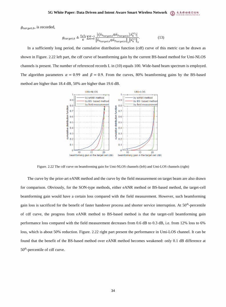
5G White Paper: Data Driven and Intent Aware Smart Wireless Network
34
𝑔𝑡𝑎𝑟𝑔𝑒𝑡,0, is recorded,
𝑔𝑡𝑎𝑟𝑔𝑒𝑡,0 ≜𝑆ℎ𝑆𝑣
𝐾∑
|⟨(�⃗� �̅�𝑡𝑎𝑟𝑔𝑒𝑡,0⊗�⃗� �̅�𝑡𝑎𝑟𝑔𝑒𝑡,0),ℎ⃗⃗ 𝑘(𝑐)
⟩|
‖�⃗� �̅�𝑡𝑎𝑟𝑔𝑒𝑡,0⊗�⃗� �̅�𝑡𝑎𝑟𝑔𝑒𝑡,0‖2‖ℎ⃗⃗ 𝑘
(𝑐)‖
2
𝐾−1𝑘=0 . (13)
In a sufficiently long period, the cumulative distribution function (cdf) curve of this metric can be drawn as
shown in Figure. 2.22 left part, the cdf curve of beamforming gain by the current BS-based method for Umi-NLOS
channels is present. The number of referenced records L in (10) equals 100. Wide-band beam spectrum is employed.
The algorithm parameters 𝛼 = 0.99 and 𝛽 = 0.9. From the curves, 80% beamforming gains by the BS-based
method are higher than 18.4 dB, 50% are higher than 19.6 dB.
Figure. 2.22 The cdf curve on beamforming gain for Umi-NLOS channels (left) and Umi-LOS channels (right)
The curve by the prior-art eANR method and the curve by the field measurement on target beam are also drawn
for comparison. Obviously, for the SON-type methods, either eANR method or BS-based method, the target-cell
beamforming gain would have a certain loss compared with the field measurement. However, such beamforming
gain loss is sacrificed for the benefit of faster handover process and shorter service interruption. At 50th-percentile
of cdf curve, the progress from eANR method to BS-based method is that the target-cell beamforming gain
performance loss compared with the field measurement decreases from 0.6 dB to 0.3 dB, i.e. from 12% loss to 6%
loss, which is about 50% reduction. Figure. 2.22 right part present the performance in Umi-LOS channel. It can be
found that the benefit of the BS-based method over eANR method becomes weakened: only 0.1 dB difference at
50th-percentile of cdf curve.

5G White Paper: Data Driven and Intent Aware Smart Wireless Network
35
3.5 Radio Transmission Technologies
3.5.1 Use case 10:Deep learning aided codebook design for grant-free NOMA
(1) Description
Grant-free non-orthogonal multiple access (NOMA), which exploits the joint benefit of grant-less access
mechanism and non-orthogonal signal superposition, has been considered to simultaneously realize low latency and
high-efficient massive access. In grant-free NOMA, data transmissions are autonomously activated by users
without explicit dynamic grant, which greatly reduces the control/user plane latency caused by signaling interaction
and scheduling grant. However, due to the decentralized instant transmissions in grant-free NOMA, the activity
information is unknown at the receiver. Moreover, the unexpected inter-user interference leads to the deteriorated
transmission reliability.
Unlink grant-based NOMA being designed following the classical multi-user information theory, grant-free
NOMA does not obey the conventional Shannon information theory and is usually designed empirically. For
example, at the transmitter side, grant-free mechanism is directly introduced into the state-of-art grant-based
NOMA schemes. At the receiver side, some resort to compressive sensing-based approaches, and some consider
the message passing algorithm-based methods. Although existing schemes have significantly contributed to the low
latency multi-user radio access, few have focused on the end-to-end optimization of the entire grant-free NOMA
system. The major obstacle lays in the fact that the introduction of random user activation behavior and
non-orthogonal transmissions makes the grant-free NOMA non-trivial to be mathematically modeled and optimized
by traditional optimization methods. To this end, this work focuses on the end-to-end optimization of grant-free
NOMA based on deep learning (DL) [16].
(2) Solutions
Consider a typical uplink grant-free NOMA system with L users and a base station (BS), where each user may
activate and transmit signals in each time interval with probability α, 0 <α ≤ 1. The activation probability can
either be acquired according to the traffic models of users, or be estimated by the BS according to the historical
data. The source bits of each user are first modulated and then mapped to a symbol sequence according to
user-specific symbol spreading signature. The receiver jointly detects the user activity as well as source bits as
shown in Figure. 2.23.

5G White Paper: Data Driven and Intent Aware Smart Wireless Network
36
Figure. 2.23: System model of Grant-free NOMA.
To couple with the system model of grant-free NOMA, a specially designed end-to-end network model based
on deep variational auto-encoder (VAE) is considered to parameterize the proposed variational optimization
problem, which consists of a NOMA encoding network and a NOMA decoding network as shown in Figure. 2.24.
NOMA encoding network models the random user activation and symbol spreading. Different from the
conventional VAE which employs a fully-connected neural network at the encoder, the proposed encoding network
of DL-aided grant-free NOMA is composed by L isolated sub-networks, since the users cannot obtain external
information from other users before transmission.
NOMA decoding network jointly estimates the user activity and the transmitted symbols. In uplink NOMA,
the receiver aims to jointly detect L signal streams. Therefore, a fully-connected neural network can be deployed as
the probabilistic decoder. Due to the grant-free access mechanism, the receiver shall also identify the user activity.
Intuitively, the reconstructed symbols hold the information about whether a user is activated. To this end, we just
add a single layer with Bernoulli output after the decoder to detect the user activity with ultra-low complexity.
Figure. 2.24: Detailed network structure
To achieve detection accuracy gain over conventional grant-free NOMA, the key is to properly train this
network. The loss function compares the differences between estimated output and real output, whose design
greatly affects the performance of deep learning. A novel multi-loss function is introduced to train the proposed
network, which includes a symbol reconstruction loss and a user activity detection loss. Specifically, the prior
information of user’s activation probability is exploited by introducing the confidence penalty in the loss function.

5G White Paper: Data Driven and Intent Aware Smart Wireless Network
37
The spreading signatures and receiving algorithm can be obtained according to the training results of NOMA
encoding and decoding networks, respectively.
(3) Performance evaluations
In this section, experiments and Monte-Carlo simulations are conducted to validate the performance gain of the
proposed DL-aided grant-free NOMA. Both linear and non-linear spreading signatures are derived by training the
proposed network, which show remarkable gain on the transmission reliability than conventional grant-free NOMA
schemes.
Non-linear symbol spreading signatures, i.e., different modulation symbols correspond to different spreading
signatures, can be illustrated by multi-dimensional constellations where each source message corresponds to a
multi-dimensional constellation point. Figure. 2.25 illustrates some examples of the learned multi-dimensional
constellations with various message sizes and activation probabilities. First of all, we can observe that constellation
projection operation and sparse RE mapping manner are naturally learned in the proposed scheme, which can
reduce the receiving complexity. Besides, the learned constellation tends to transmit signals with various power
levels in 4 Res, which inherently introduce power gain differences and can facilitate the interference cancellation.
These observations show that DL-aided grant-free NOMA automatically tap into some physical insights on the
design of spreading signature, which conventionally requires expert knowledge in wireless communications.
Figure. 2.25: Examples of the learned multi-dimensional constellations of one user in 4 Res with different modulation order M. In each
example, the 4 points with the same color and shape in 4 Res constitute a four-dimensional constellation point.
While multi-dimensional constellation normally requires iterative-based detection methods which dissatisfy
the low latency services, we apply a linear constraint to derive linear spreading signatures for grant-free NOMA,
where all modulation symbols of a user have the same spreading signature. This helps to implement simple
detectors, e.g. match-filter (MF) detection. With the setting of UE number L=6 and spreading factor K=4, a

5G White Paper: Data Driven and Intent Aware Smart Wireless Network
38
randomly generated example of the learned spreading signature set is shown above, where the l-th column is the
normalized spreading signature of user-l.
Figure. 2.26: SER vs SNR with various activation probabilities Figure. 2.27: SER performance of the proposed scheme
Symbol error rate (SER) of the proposed scheme is evaluated in Figure. 2.26 and Figure. 2.27. As shown in
Figure. 2.26, we first compare the achievable SER of the linear spreading signatures generated by the proposed
scheme with state-of-art grant-free NOMA schemes, i.e., welch-bound equality (WBE) sequences and sequences of
multi-user shared access (MUSA), under a simple MF receiver. It is observed that SER reduction can be achieved
compared to conventional grant-free NOMA while not introducing any increase in receiving complexity or latency.
We then employ the DNN-based receiver (DNNrx), which constitutes a near maximum-likelihood (ML) receiver
and is trained along with the linear spreading signatures. In this case, 10-3 SER can be achieved with various
activation probabilities, which is promising to satisfy the rigorous requirement on the reliability.
SER performance of the proposed scheme with various M is shown in Figure. 2.27. It is observed that
ultra-high reliability is achieved with various M, which validates the universality of the proposed scheme. Besides,
we observe that multi-dimensional signatures achieve slightly better SER performance than linear signatures with
DNNrx. This is because the multi-dimensional signatures are more flexible than its linear counterparts. However,
maximum-likelihood based detection algorithms are required to distinguish multiple data streams with
multi-dimensional signatures, which leads to large detection delay and high complexity. On the contrary, the
overlapped signals with linear spreading signatures can be quickly separated even with a very simple receiver, e.g.
MF receiver as shown in Figure. 2.26.
3.6 Discussion on the wireless big data and AI/ML algorithms for wireless network
applications
In [2], the wireless big data and AI/ML algorithms are presented in Table 1, which gives a useful mapping between

5G White Paper: Data Driven and Intent Aware Smart Wireless Network
39
the use cases and the potential AI algorithms along with the required wireless big data. In this section, we aims to
provide more insights for the future works on the algorithms and requited data via updating the table based on the
recent progress presented in this whitepaper and also that in the series of whitepapers [1-3].
It can be seen from the Table. 2.5, various well known learning algorithms are widely utilized in the wireless
network use cases. However, most of them are designed originally for other domains, e.g., the image processing or
nature language processing, which is obviously not optimized for the wireless network. How to leverage the
wireless domain specific information and existing wireless communication theory and models to design and further
improve the intelligent algorithms suitable for wireless network application still needs further study.
Table 2.5 Wireless Big Data and AI/data analytics for wireless Network Applications
Use Cases AI Algorithms Related Wireless Big Data
Intelligent
Network
Management and
Orchestration
Coverage Hole Discovery K-means,
Supervised Learning
Call trace, UE measurement
report (MR), location, radio
link failure, etc.
QoE Issue Debugging Decision Tree
Control plane signaling,
user plane data, webpage
downloading time, round
trip time, delay, jitter,
packet loss rate, etc.
Network Energy Efficiency
Optimization Neural Network
MR, cell performance
metric (PM), network
configuration parameters
(CM) and user xDR data
Coverage and Capacity
Optimization Deep Q Learning MR, PM, CM, etc.
KPI Anomaly Detection Clustering, Autoencoder,
Decision Tree
Fault data, PM counter,
CM, etc.
KPI Anomaly Diagnosis
Clustering, e.g.,
K-means; isolate Forest;
Rule based
Fault data, PM counter,
CM, etc.
Smart Carrier Licence Resource
Scheduling CNN+LSTM, DNN
KPI counters, e.g., UL/DL
PRB usage, PDCP
throughput,
Geo Data Enhanced Coverage
Estimation and Planning
Statistical data analytics
and data visualization
GNSS, Finger-printing,
TDOA, RSRP/RSRQ,
network geography
information
Intelligent MEC
Proactive Cache
Collaborative Filtering,
Deep/Reinforcement
Learning (RL)
User XDR data that can
reflect user request behavior
and mobility pattern etc.
AI powered QoE Cross-Layer
Optimization Neural network
PDCP buffer, base station
load, MAC rate, service
type, packet error rate, etc.
AI Based Positioning and
Localization DenseNet, CNN, DNN
channel impulse response
Amplitude and phase
Intelligent Radio Service Type Recognition Neural Network, CNN, User XDR data that reflects

5G White Paper: Data Driven and Intent Aware Smart Wireless Network
40
4 Intent Aware Wireless Network
4.1 Motivation
Recently, the AI technologies such as machine learning and big data analytics are developing very quickly, and
they are also applied in wireless networks to reduce human labor and improve network performance. Intent aware
network management is one of most important applications of those technologies.
Compared to existing human-oriented network management, intent aware network management uses simple
instructions to tell the network “what to do” rather than “how to do” to improve the network automation capability
and reduce errors caused by manual decision making. Moreover, in the scenarios of the vertical industry, it is
Resource
Optimization
Naïve Bayes, SVM, etc. service pattern
Resource Management for
Network Slicing DQN, GAN-DDQN
MR, Number of arrived
packets in the window time,
SE, QoE performance,
allocated per slice resources
etc. s
Customized Mobility
Management
Neural Network, Deep
Reinforcement Learning,
SVM
MR, PM, CM, load, user
XDR data that reflects user
mobility pattern
Big Data Analysis for Handover
Optimization in Massive-MIMO
Cellular Systems
SVM, DNN, beam
spectrum storage
RSRP, RSRQ, beam info,
user handover signaling
logs and performance, etc
Intelligent Admission control &
Proactive Resource Allocation Reinforcement Learning
MR, performance metrics,
user XDR data that reflects
user mobility pattern
User Portraits assisted User
Scheduling SVM, KNN, etc.
MR, terminal type, chip
type, transmission capacity ,
service type, buffer length
Virtual Grid Enabled Network
Performance Optimization Neural Network
History KPI statistics, MR,
etc
User Time-Frequency Resource
Scheduling
Deep Neural Network,
Reinforcement Learning
Quality of service (QoS),
channel quality indicator
(CQI), guaranteed bit rate
(GBR), RLC buffer size,
historical rate, service type,
resources
Intelligent Radio
Transmission
Technologies
Wireless Big Data Assisted
Channel Modeling Neural Network, PCA Channel measurement data
OFDM/MIMO Detection Deep Learning Channel information,
transmit/receive data
AMC
/Rank Indicator (RI)
Optimization
Reinforcement Learning,
Neural Network,
Random Forest
Signal to interference and
noise ratio (SINR), CQI,
ACK/NACK, etc.
Codebook design for grant-free
NOMA
deep variational
auto-encoder (VAE)
User transmitted signals,
user activation probability

5G White Paper: Data Driven and Intent Aware Smart Wireless Network
41
important that the intent aware network management can help the vertical industry customers manage the network
without getting into the detail of network since the vertical industry customers may not have sufficient network
operation and maintenance knowledge.
Currently, the northbound interface (Itf-N) defined in 3GPP SA5 is based on the network resource model (NRM),
which is intended to model all the network resources of the managed objects in the wireless network. So that,
Network Management System (NMS) can directly add, delete and change all management objects through
Configure Management (CM), Performance Management (PM), Fault Management (FM) and other types of
operations, which relies heavily on expert knowledge and experiences. Since wireless networking products have
thousands of parameters that can be used for wireless resource management and user service quality assurance
management, it is very difficult to conduct the optimal solutions and avoid the errors during the network
management manually. In addition, different vendors may have a lot of proprietary implementations for
competitive differentiation, which further increase the difficulty of the network OAM under multi-vendor
interoperability scenarios.
The intent aware network uses the intent model to express the network management requirements, which only
involves the purpose description and the general term of the domain. The intent system is used to map the
standardized intent model to the vendor-specific network management task to achieve multi-vendor interoperability.
Then, the automation mechanisms, e.g., data-driven technologies, data analytics and AI/ML can be applied to
accomplish the translated network management tasks. Figure 3.1 illustrates the evolution from NRM based
management to intent aware/driven management.

5G White Paper: Data Driven and Intent Aware Smart Wireless Network
42
Figure 3.1 Evolution from NRM based management to Intent driven management
4.2 Use Cases for intent aware wireless network
4.2.1 Use Case 1: Intent driven network service provision
The service provider expresses his intent for a network by providing high level requirements such as the service
type to be supported with corresponding geographical areas and time durations, maximum number of UEs, DL/UL
throughput per UE, etc. to the intent system of the network operator. The service provider does not care about what
network elements are used and how to connect those network elements.
The intent system translates the network deployment intent for the specific area to the network deployment related
requirements (e.g., using network slice or not, network topologies, etc.) and the configurations (e.g. DL/UL
throughput per cell and UE measurements) for the management network equipment in this specific area. According
to these network related requirements, the network uses the network provisioning procedures (e.g., network slice
instance creation) to provide required network instance and communication service for the specific UE, and
continuously monitor the managed network equipment to ensure the intent.
Figure 3.2 intent driven network service provision
4.2.2 Use Case 2: Intent driven network provision and assurance for 5G vertical services
Vertical customers are becoming increasingly important for operators in 5G era. It is crucial for operators to
provide a service for vertical users, where they can customize or select service blueprints from a predefined
5G White Paper: Data Driven and Intent Aware Smart Wireless Network
43
catalogue, configure and instantiate, operate and monitor their network status for their vertical services. It worth
noting that the vertical customers may not have a detailed knowledge about the network. Therefore, the intent
approach allows the vertical users to focus only on the business aspects of their services (e.g., how many users need
to be supported with what kind of throughput, latency and mobility performance assurance, and/or the level of
required security). The network operator can translates the vertical’s demands into a number of network specific
features and requirements and identifies the best combination of the network features and optimization parameters
to deliver the requested services. If the network slicing is supported, the network operator (intent producer) can use
the networks slice requirements defined in the [17] to create or reconfigure the network slice instance. If the
network slicing is not supported, the network operator can derives the network requirement and provides the
requirements via consuming the intent/policy service provided by the network elements. Another alternative
approach is that network operator can directly drive the network configuration parameters for the network elements
to ensure the network service provision, the parameters can be enhanced based on the current SA5 network
resource model [18].
To deliver the network provision and performance assurance for 5G vertical services, the intent model and intent
enforce scope needs to be investigated. One potential intent model for this use case is to express the intent with the
network objectives. The scope can be used to identify the network slice type, application type, QoS flow. It may
also include the time/duration and geography constraints. The network objective for the intent may vary due to
different vertical service requirements. Taking the electronic vertical service as an example, the intent objective
may include service/slice type together with the service/slice profile, e2e latency, guaranteed UL/DL flow bit rate,
synchronization timing requirement, etc.
4.2.3 Use Case 3: intent/policy driven network optimization for user QoE assurance
HD video, cloud VR and gaming are envisioned to be the most promising applications in early 5G era. These
applications are usually bandwidth consuming, or even latency sensitive. For such traffic-intensive and highly
interactive applications, with potentially significant fluctuation of radio transmission capability, users may often
suffer from stalling, which causes the user QoE deterioration. Operators have already been strive hard to guarantee
network performance for the network KPI perspectives, but the assurance of KPIs sometimes cannot effectively
reflect the actual user experience. Instead of the traditional KPI or QoS targets delivered by the network, the user
QoE is the actual crucial factor to guide the network optimization.

5G White Paper: Data Driven and Intent Aware Smart Wireless Network
44
QoE is normally measured at application layer based on application layer info, but it’s also possible for network to
estimate or predict the user experience based on network side info and then perform network optimization for QoE
assurance. Multi-dimensional data, e.g. user traffic data, network measurement report, application layer QoE value,
can be acquired and used for offline ML model training of a QoE estimation model. The model inference will be
executed in a real-time manner in the mobile communication system to estimate or predict the user experience
based on network side info. The estimated QoE value at network side is approximately to the QoE value which will
be measured at application layer later, but it’s estimated at network in real time, so network could decide to
optimize the network resource in real time to improve the user experience.
4.2.4 Use Case 4: Intent driven network performance optimization
Due to some user complaint information received, the operator expresses his intent that the performance of network
needs to be optimized to satisfy certain requirements. For example, the percentage of users with experienced data
rate < 5 Mbps should be less than 1 %, and the average experienced data rate should be greater than 7 Mbps. Based
on the intent received, the intent system detects the potential network issues which lead to the poor performance
(e.g. experienced data rate < 5 Mbps), which may be the handover is happened frequently between some neighbor
Cells, or some weak coverage area with large number of users, etc. An example is illustrated in Figure. 3.3.
The intent system decides the network optimization methods (e.g. coverage and capacity optimization, handover,
machine learning, etc.) to be used and derives the corresponding parameters (e.g. policy for handover) for the
selected network optimization methods. For example, intent system decides to trigger coverage and capacity
optimization to enhance the coverage for the weak areas and triggers the handover optimization to reduce the
frequency of handover between certain neighbor Cells.
The intent system may adjust and monitor the network iteratively until the performance optimization intent is
satisfied. The intent system may also notify the operator the fulfillment information of the network optimization
intent (e.g. fulfill or not)

5G White Paper: Data Driven and Intent Aware Smart Wireless Network
45
Figure 3.3 Intent driven network performance optimization
4.2.5 Use Case 5: intent driven traffic steering optimization
The objective of traffic steering optimization is to enhance the efficiency of resource utilization among multiple
cells/carriers as well as providing a consistent user experience. To achieve this goal, multiple radio resource
optimization algorithms can be considered, e.g., mobility load balancing, user carrier association, user flow control.
With the increasing bands, it becomes quite complicated and challenging for the network operator to steer the
traffic in a balanced distribution and provide good network performance and user experience. In this case,
intent/policy approach can simplify the problem of complex network traffic optimization. The network operator
expresses its intent/policy that the traffic in the specified scope needs to be optimized to satisfy certain optimization
objectives under given constraints (e.g., carrier priority settings for UEs with specific type of services). The traffic
optimization objectives can be cell level KPIs utility functions (e.g., maximize energy efficiency, minimize power
consumption, maximize throughput, balance load) and Per-UE/Per-service level targets (e.g., latency, bit data rate).
In order to optimize network traffic dynamically and flexibly for diversified scenarios, the optimization
intent/policy is flexibly configured to reflect the per-user or per-user group or per-service level QoS objectives and
the network resource and energy efficiency demands. The network resource usage guidance, e.g., frequency bands
usage preference can also be provided via the intent services to network based on the intent of the network manager
and data analytics derived from the historical network configuration and performance data.

5G White Paper: Data Driven and Intent Aware Smart Wireless Network
46
Based on the intent/policy received, the network element translate the intent/policy and take necessary actions to
enforce the policy to achieve the network traffic optimization objectives.
4.3 Reference Architecture for the intent aware wireless network
Figure 3.4 Intent Aware Network Reference Architecture
According to the aforementioned use cases, different kinds of intents will be existed in the wireless network,
including:
⚫ The intent from Communication Service Consumer (Intent-CSC) enables Communication Service
Consumer (CSC) to express what CSC would like to do for the communication service management
without knowing the details of the network and service operation.
⚫ The intent from Communication Service Provider (Intent-CSP) enables Communication Service provider
(CSP) to express an intent about what CSP would like to achieve in the network management without
having professional knowledge of network level operations.
⚫ The intent from Network Operator (Intent-NOP) enables Network Operator (NOP) to provide what NOP
would like to do for the network resource management without having professional knowledge of
network equipment level operation or virtualized infrastructure level operation.
Figure 3.4 shows the intent aware network reference architecture, where a hierarchical intent systems are
introduced in different level of management entities such as Business Support System (BSS), Network
Management System (NMS) and Equipment Management System (EMS), etc. The intent system composes of two

5G White Paper: Data Driven and Intent Aware Smart Wireless Network
47
main modules: Intent Engine and Intent Executor.
⚫ The Intent Engine is responsible for receiving intents and translating them to the executable actions for
network deployment and service assurance or other intents. The intent is expressed in declarative
language, i.e., only describe what to do rather than how to do. The translation depends on the
management knowledge that can be defined by experts or learned from the historical data.
⚫ The Intent Executor interacts with the underlying networks to execute the policies and the tasks derived
from the intent by the Intent Engine. The Intent Executor may utilize closed-loop automation mechanisms
to continuously monitor the network performance and service experience, analyses the abnormal event
and adjust the network automatically to meet the intent requirement. Some SON and slicing automatic
mechanisms can be reused by the intent system if needed.
The Intent aware network management and the traditional network management are expected to be co-exist for a
long time with the network evolution. The potential way to apply intent is as follows:
⚫ For the intent system in BSS, Intent Engine receives the Intent-CSC, and translates it into Intent-CSP and
network level requirements, then may invoke Intent system or the traditional management service in
NMS to fulfil the intent-CSC..
⚫ For the intent system in NMS, Intent Engine receives the Intent-CSP from the BSS and translates it into
sub-intent for NOP or network element level requirements, then may invoke Intent system or the
traditional management service in EMS to fulfil the intent-CSP.
⚫ For the intent system in EMS, Intent Engine receives the Intent-NOP from the NMS and translates it into
detailed network element operational requirements, then takes internal closed-loop automation to fulfill
the intent-NOP.
4.4 Intent Expression Model
An intent is a desire of the service consumer/service provider/network operator to reach a certain objective or state
for a network deployment or service assurance. The intent expression can be a machine-readable declarative
language, and it must be interpreted by the intent engine without any ambiguity.
The main body of the intent expression describes the main purposes that the intent is intended to achieve. It
indicates the target object of the intent (e.g., cells, base stations, VNFs, QoS flows, etc.), and the actions that need
to be perform to the objects (e.g., cell rehoming) or some desired objectives need to achieve (e.g., average UE
throughput larger than 10Mbps).The intent expression may also include the specification of the target objects (e.g.,

5G White Paper: Data Driven and Intent Aware Smart Wireless Network
48
the location/area information, software version, TDD or FDD, etc.), the constraints on when the intent takes
effective (e.g., the time duration, threshold of certain KPIs, etc.), and some extra information to be referenced by
the intent fulfillment process. The extra information can be the deployment scenarios of the network (e.g., dense
urban, high speed, etc.) or the service types (e.g., eMBB, URLLC, mMTC, etc.).
4.5 Technical Key Issues
⚫ Intent modeling and translation
The intent system needs to translate the intent into network requirements and corresponding management tasks and
continuously maintain the fulfillment of the intent in the network. Firstly, a suitable language model need to be
established. Then, with the language model and the network corpus in the network knowledge base, the required
network KPI and optimization objective are extracted from the intention expression using semantic processing
algorithms such as named entity recognition. Finally, according to the prior knowledge in the network knowledge
base, the corresponding management tasks (e.g., operational workflow or optimization algorithm) are derived.
⚫ Intent verification and conflict resolution
It is necessary to perform consistency check on the intent translation results and take appropriate actions or policies
to apply so as to ensure the accuracy of intent translation and fulfillment. And during the intent fulfillment process,
management actions or policies can be dynamically adjusted since the wireless network is a time-varying
environment. Moreover, the intent system needs to consider the conflict resolution with existing intents in the
network when new intents arrive since the new intents and the previously activated intents may overlap in terms of
operation scopes, network element parameters, scheduling of wireless network resources, etc. It may cause the
problems such as parameter adjustment conflicts, insufficient allocation of wireless network resources, and degrade
of network performance. After an intent conflict is detected by intent system, it will provide a resource adjustment
strategy for resolving the intent conflict, improving the network management efficiency, and avoiding the current
network performance degradation.
⚫ Intent assurance and network performance optimization
The key challenge of intent assurance is the adaptive adjustment of network parameters for time-varying wireless
network. With the collected data (e.g., UE measurement data, real-time wireless performance data) , the wireless
intent system extracts the temporal and spatial characteristics of the data, and then t evaluate whether the network

5G White Paper: Data Driven and Intent Aware Smart Wireless Network
49
state meet the intent requirements after executing the current configuration policies. If the intent requirements have
been met, current network configuration will be kept. Otherwise, the intent system will find the optimal
configuration to meet the intent requirement according to the current network state and historical data.
4.6 Intent Service Evolution Consideration
The wireless network is envisioned to have 5 levels of autonomy along its evolution path, from assisted operation
& maintenance (Level 1), partial autonomous network (Level 2), conditional autonomous network (Level 3), highly
autonomous network (Level 4) to full autonomous network (Level 5) [3] . The fulfillment of the intents relies on
the autonomous capabilities of the wireless network. With the network automation evolution from level 2 to level 5,
management capabilities (e.g., requirement mapping, context awareness, abnormal detection, decision and
execution) and management tasks (e.g., design, deployment, maintenance and optimization) are gradually replaced
and enhanced by the machine, which makes the intent translation and fulfillment more mature, so that the intent
expression can cover more scenarios and the intent fulfillment can be done with closed-loop automation and be
more effective and robust.
5 Standards Progress in 3GPP/ITU/ETSI and Consideration
5.1 ITU-T ML5G
In July 2019, ITU-T SG13 approved the Architectural framework for machine learning in future networks
including IMT-2020 submitted by the focus group in March 2019 as a technical specification. This specification
contains the following information:
• Terminology for ML in the context of future networks
• Architecture framework for machine learning in future networks and 5G
• Guidance for applying the architecture framework to specific technologies (such as 3GPP, MEC, edge
network, or transport network).
Now, ITU-T FG-ML5G has started the second phase (which lasts until July 2020). The following recommendations
and supplement were consented and approved by SG13 in June and Oct. 2019 meeting.
• Architectural framework for machine learning in future networks including IMT-2020 [19]

5G White Paper: Data Driven and Intent Aware Smart Wireless Network
50
• Use cases and basic requirements of machine learning in 5G and future networks [4]
• Data handling framework to enable Machine Learning in 5G and future Networks [20]
• Methods for evaluating the intelligence level of mobile networks.
5.2 3GPP
5.2.1 SA2
3GPP SA2 Enablers for Network Automation for 5G’s fRel-16 work finished this June 2019. It’s output has been
documented in New TS23.288, "Architecture enhancements for 5G System (5GS) to support network data analytics
services (Release 16)". In this TS, following aspects have been defined:
- the reference architecture for data analytics;
- network data analytics functional description;
- procedures for analytics exposure, for data collection,
- procedures for specific analytics for following use cases: Slice load level, Observed Service experience
related, NF load, Network Performance, UE mobility, UE communication, and Expected UE behavioral
parameters;
- NWDAF services description.
3GPP SA2 now continues this topic’s work in Rel-17, and the study target will be finished in March 2020. This
study focuses on: multi-NWDAF architecture for roaming scenario, new use cases, the interaction between
NWDAF and AI training platform, and deployment for specific scenarios.
5.2.2 SA5
3GPP SA5 Intent driven management service for mobile network (IDMS_MN) started in Sep. 2018, including two
phases: study item and work item. This work aims to study mobile network communication intent-driven
management scenarios that improve O&M efficiency and define intent-driven management service interfaces to
implement automatic closed-loop control, and to implement simplified control of complex networks or services.
The study item is expected to finish in end of 2019. The objective of it is as follows:
- Investigate the potential scenarios which could benefit to the operators from the intent driven
management services.

5G White Paper: Data Driven and Intent Aware Smart Wireless Network
51
- Study the scenarios which may utilize automation mechanisms including SON to satisfy the intent
driven purposes.
- Investigate the appropriate mechanism to describe the intent.
Currently (V0.7.0, Sep. 2019), the content of its document (3GPP TR 28.812) contains the concepts, 16 scenarios
and the standard consideration of intent driven management service.
The work item will start in Oct. 2019, whose objective is:
- Specify the typical management scenarios which operators could benefit from the intent driven
management services in the multiple vendor environment. The scenarios should help to improve the
multiple vendor operational efficiency on network management.
- Specify the intent driven management services’ requirements which are derived from the scenarios
above.
- Specify the intent driven management services which may include the management operations,
management entities and management information.
In September 2019,3GPP SA5 also started a new study on enhancement of Management Data Analytics Service
(MDAS), its objectives are as follows [21]:
• The use cases, potential requirements and possible solutions regarding the relation and interaction
between MDAS and other NF functionalities (including NWDAF and SON functionalities).
• Management aspects (e.g., in connection with Machine Learning techniques) of Management Data
Analytics.
• Development of scenarios (including exploration of potential consumers), use cases, potential
requirements and possible solutions (including the recommended probable actions) for the following
aspects, based on the MDAS concept:
• Root cause analysis for ongoing network and service configuration and performance related issues;
• Prevention of potential issues affecting the network and service operation, e.g., the preventative actions
are required to avoid network and service performance degradation;
• Prediction of network demands (e.g. capacity upgrades and new/re-deployments) to accommodate
potential load change and/or new service deployments;
• SLA assurance, for example related to network slices.

5G White Paper: Data Driven and Intent Aware Smart Wireless Network
52
• Support of the optimization of networks, services and functionalities;
• Support of the automation of network and service management;
• The management data analytics capability to support B2B services;
• The management data analytics capability exposure and data collection mechanism with the vertical
management system (e.g. AF management system);
• Input and output data of the MDAS to realize the items above-mentioned.
5.2.3 RAN3
3GPP RAN WG3 started RAN-centric Data Collection and Utilization SI in June 2018. The objective is to study
the wireless big data collection and application oriented to network automation and intelligence, including the
process and information interaction required for studying different use cases. During the study phase, the work
focuses on studying the use cases and benefits of RAN centric Data utilization, e.g. SON features including
mobility optimization, RACH optimization, load sharing/balancing related optimization, Minimization of Drive
testing (MDT) etc. Based on the evaluations on the use cases, Identify necessary standard impact and the procedure
for configuration and collection of UE measurements, L2 gNB/en-gNB measurements and signalling procedure for
problem analysis.
In June 2019,the study phase finished and the corresponding WI was approved in RAN#84 meeting which aimed
to be completed in February 2020. Detailed discussion on the impact to the spec are ongoing in RAN2 and RAN3,
including impact to NGAP.S1AP,x2AP,XnAP,E1AP,F1AP and also the Uu interface. Until now,50% is completed.
5.3 ETSI ENI
ETSI ISG ENI Intent Aware Network Autonomy (ITANA) work item started in Jun. 2019, and expected to finish
in Jul. 2020. The scope of it is: "This Work Item will describe the motivation, requirements, and key issues of using
intent policies to manage the operation of networks and networked applications in various domains. This Work
Item will explore how to define and use intent policies. Options include (1) define intent using a Controlled
Language and translate that to software, (2) define intent using a Controlled Language and translate that to a DSL,
(3) define intent using a DSL and translate that to software, or (4) use a DSL to define and use intent.
This document will discuss various design options, in terms of a set of new stand-alone and/or nested Functional
Blocks, for using intent with the ENI System Architecture. This includes accepting and validating intent statements,

5G White Paper: Data Driven and Intent Aware Smart Wireless Network
53
determining how intent affects the goals and operation of the ENI system, and how it is used by business users,
application developers, and network administrators. The recommendations and conclusions of this report will be
contributed to other ENI group specifications.
6 Summary
Towards the smart wireless network, this whitepaper tries to investigate the data driven and intent aware
wireless network. The use cases and potential solutions for data driven wireless network are discussed and
updated based on the recent progress and our previous two whitepapers. The ML algorithms utilized in the all the
use cases of the series of whitepaper are also discussed and summarized to provide some insight for the researcher
on the future works. Leveraging the data driven solutions, to further enhance the network intelligence, simplify the
network management complexity and offer simplified management capability towards the vertical industries, the
intent aware wireless network is proposed. The motivation, concept, use cases and reference architecture are
presented. The intent expression model, technical key issues and intent service evolution are discussed as well.
The standards progress related to wireless big data and AI as well as the of potential standards impacts are also
discussed.
As the key guiding documents for future works, the series whitepaper on smart 5G/wireless network are
expected to help readers better understand how to bring the WBD and AI/ML into wireless network towards the
intelligence wireless ear. The latest achievements will be presented in annual updates of this white paper or
technology review reports. A collective wisdom and especially more efforts among SIG members and others
partners are continuously expected.
We sincerely invite all mobile operators, telecom equipment manufacturers and IT system manufacturers, as
well as industrial and academic research institutions of interest to join us and work closely to deliver the smart
wireless network vision.
7 Reference
[1] FuTURE Forum 5G SIG, Whitepaper, “Wireless Big Data for Smart 5G”, Nov. 2017, online available:
http://www.future-forum.org/dl/171114/whitepaper2017.rar.
[2] FuTURE Forum 5G SIG, Whitepaper, “Mobile AI for Smart 5G-Empowered by Wireless Big Data”, Nov.
2017, online available: http://www.future-forum.org/dl/171114/2018mwc.rar.
[3] FuTURE Forum 5G SIG, Whitepaper, “Wireless Big Data and AI for Smart 5G & Beyond,” 2018.
[4] ITU-T Supplement 55 to Y.3170 series, “Machine learning in future networks including IMT-2020: use
cases”, 2019.

5G White Paper: Data Driven and Intent Aware Smart Wireless Network
54
[5] Shuiwang Ji, Wei Xu, Ming Yang, and Kai Yu. 2013. 3D convolutional neural networks for human action
recognition. IEEE Transactions on Pattern Analysis and Machine Intelligence 35, 1 (2013), 221–231.
[6] P. V. Klaine, A. I. Muhammad, O. Oluwakayode, et al., “A Survey of Machine Learning Techniques Applied
to Self Organizing Cellular Network,”, IEEE Commun. Surveys &Tutorials, 2017
[7] Y. Hua, R. Li, Z. Zhao, H. Zhang, and X. Chen, “GAN-based Deep Distributional Reinforcement Learning for
Resource Management in Network Slicing,” in Proc. IEEE Globecom 2019, Big Island, Hawaii, USA, 201
[8] R. Li et al., “Deep reinforcement learning for resource management in network slicing,” IEEE Access, vol. 6,
pp. 74429–74441, Nov. 2018
[9] Jia Guo, Chenyang Yang and I Chih-Lin, "Exploiting Future Radio Resources with End-to-end Prediction by Deep
Learning," IEEE Access, vol. 6, pp. 75729-75747, 2018.
[10] Kaiyang Guo, Tingting Liu, Chenyang Yang, and Zixiang Xiong, "Interference Coordination and Resource
Allocation Planning with Predicted Average Channel Gains for HetNets," IEEE Access, vol. 6, pp. 60137-60151,
2018.
[11] Zhaoqi Xu, Jia Guo, and Chenyang Yang, “Predictive Resource Allocation with Interference Coordination by Deep
Learning,” IEEE WCSP 2019
[12] Jia Guo and Chenyang Yang, “Predictive Resource Allocation with Deep Learning,” IEEE VTC Fall 2018.
[13] Dong Liu, Jianyu Zhao and Chenyang Yang, “Energy-Saving Predictive Video Streaming with Deep Reinforcement
Learning,” IEEE GLOBECOM 2019.
[14] Changyang She and Chenyang Yang, “Energy Efficient Resource Allocation for Hybrid Services with Future
Channel Gains”, IEEE Trans. on Green Communications and Networking, early access.
[15] M.Huang and X.Zhang, “Big data analysis on beam spectrum for handover optimization in massive-MIMO
cellular systems,” Proc. Of 2018 IEEE WCNC, 2018.
[16] N. Ye, X. Li, H. Yu, A. Wang, W. Liu and X. Hou, “Deep Learning Aided Grant-Free NOMA Toward
Reliable Low-Latency Access in Tactile Internet of Things,” IEEE Trans. Industrial Informatics, vol. 15, no.
5, pp. 2995-3005, May 2019.
[17] 3GPP TS28.531, Technical Specification Group Services and System Aspects; Management and orchestration;
Provisioning.
[18] 3GPP TS28.541, Technical Specification Group Services and System Aspects; Management and orchestration;
5G Network Resource Model (NRM); Stage 2 and stage 3
[19] ITU-T Recommendation Y.3172 (2019), “Architectural framework for machine learning in future networks
including IMT-2020”
[20] ITU-T Recommendation Y.3174 (2019), “Framework for data handling to enable machine learning in future
networks including IMT-2020”
[21] 3GPP TSG-SA5 Meeting #126, S5-195631, Study on enhancement of Management Data Analytics Service.
Acknowledgement
Grateful thanks to the following contributors for their wonderful work on this whitepaper:
Leaders:

5G White Paper: Data Driven and Intent Aware Smart Wireless Network
55
China Mobile: Chih-Lin I, Chunfeng Cui, Qi Sun, Yuxuan Xie, Jie Wu, Yali Guo, Gang Li
Huawei: Yan Wang
Datang Mobile: Haichao qin, Ming Ai
ZTE: Dong Chen
Contributors:
Intel: Jianfeng Wang, Xu Zhang
DOCOMO
Beijing Labs: Wenjia Liu, , Xiaolin Hou
China Unicom: Feibi Lv, Rong Huang, Shan Liu
ZJU: Honggang Zhang, Rongpeng Li
LENOVO: Xin Guo
BUAA: Chenyang Yang, Shengqian Han, Tingting Liu
XIDIAN
University Zhenfei Xia, Liqiang Zhao
Abbreviation
3GPP the 3rd Generation Partner Project
5G the Fifth-Generation mobile communications
AI Artificial intelligence
CSC Communication Service Consumer
CSP Communication Service provider
CP Central Processor
CNN Convolutional neural network
DNN Deep Neural Network
DNNrx DNN-based receiver
DRL Deep Reinforcement Learning
DQL Deep Q learning
GNSS Global Navigation Satellite Systems
KPI Key Performance Indicator

5G White Paper: Data Driven and Intent Aware Smart Wireless Network
56
LSTM Long Short Term Memory
NRM Network Resource Model
PLS Partial Least Squares Regression
PRA Predictive resource allocation
PRA-ICIC PRA with ICI coordination
QoE Quality of Experience
RAN Radio Access Network
RSRP Reference Signal Receiving Power
RSRQ Reference Signal Receiving Quality
VOD Video-on-Demand


