5G Research @ · PDF fileHuawei 3X 3.3X 10X 100X NTT Docomo 2.8X 24X 15X 1000X ... –...
22
5G Research @ Aalto http://5g-research.aalto.fi/en /
Transcript of 5G Research @ · PDF fileHuawei 3X 3.3X 10X 100X NTT Docomo 2.8X 24X 15X 1000X ... –...

5G Research @ Aalto
http://5g-research.aalto.fi/en/
Researchers
Prof. Olav Tirkkonen, Communications theory
Self-organization, flexible spectrum user, D2DCoding theory (codebooks for massive MIMO),RF imprirments, Statistics for communicationsImplementation studies
Assist. Prof. Katsuyuki Haneda, Radio science and technology
mm-wave channel sounders, channel modeling, antenna design
Prof. Riku Jäntti, Communications engineering
Flexible spectrum use, interference modeling and control (ultradense networks), MTC (capillary/sensor networks, wireless automation), indoor DAS, Implementation studies
Prof. Jyri Hämäläinen, Mobile communications
Network architectures, relays, small cells, DAS, HetNets, RRM, public safety communications, 3GPP compliant simulation tools
Prof. Risto Wichman, Signal Proc. for communications
MIMO for LTE, Massive MIMO (channel estimation), full-duplex radio, Dirty RF, Geolocationdatabases for TVWS, Stochastic geometry
Staff Scientist Jose Costa Requena, Networking technology
Packet core virtualization, Software Defined Networking, implementation studies
Lecturer Kalle Ruttik, Communications Engineering
Software Defined Radio, C-RAN, implementation studies
Prof. Tarik Taleb, Networking technology
Radio access networks, cloud-communications
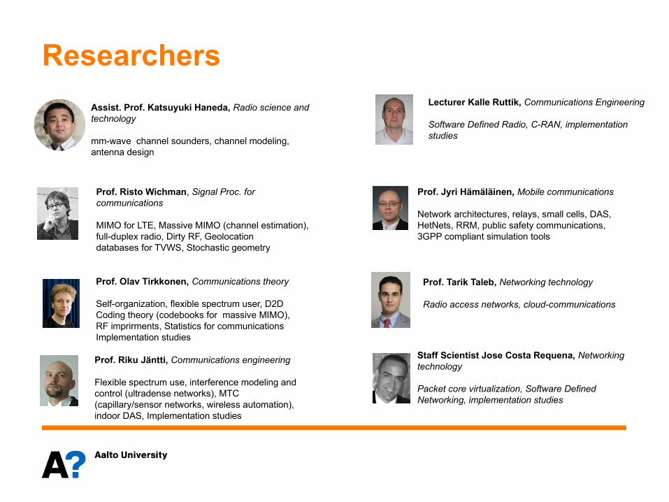
5G challenges
• 1000 x more capacity• Ultra-reliable communications
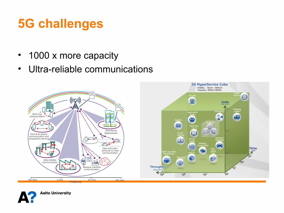
5G challenges
Author SpectrumSpectral
Efficiency DensificationTotal Capacity
Increase
NSN 10X 10X 10X 1000XHuawei 3X 3.3X 10X 100X
NTT Docomo 2.8X 24X 15X 1000X
Zander & Mähönen 3X 5X 66X 1000X
I Spectrum
5
Spectrum
• Most of the current mobile radio systems operate on overcrowded bands between 450MHz and 3.5GHz.
• On the other hand, between 3.5GHz and 60GHz there is currently around 7GHz unlisenced spectrum available, including large contiguous bands
• New access frequency can be made available much more easily on 10-60GHz than below 3.5GHz frequencies.
• In the following we introduce some new directions for the mobile systems research on mm-wave frequencies making – somewhat strong - assumptions on the channel properties.
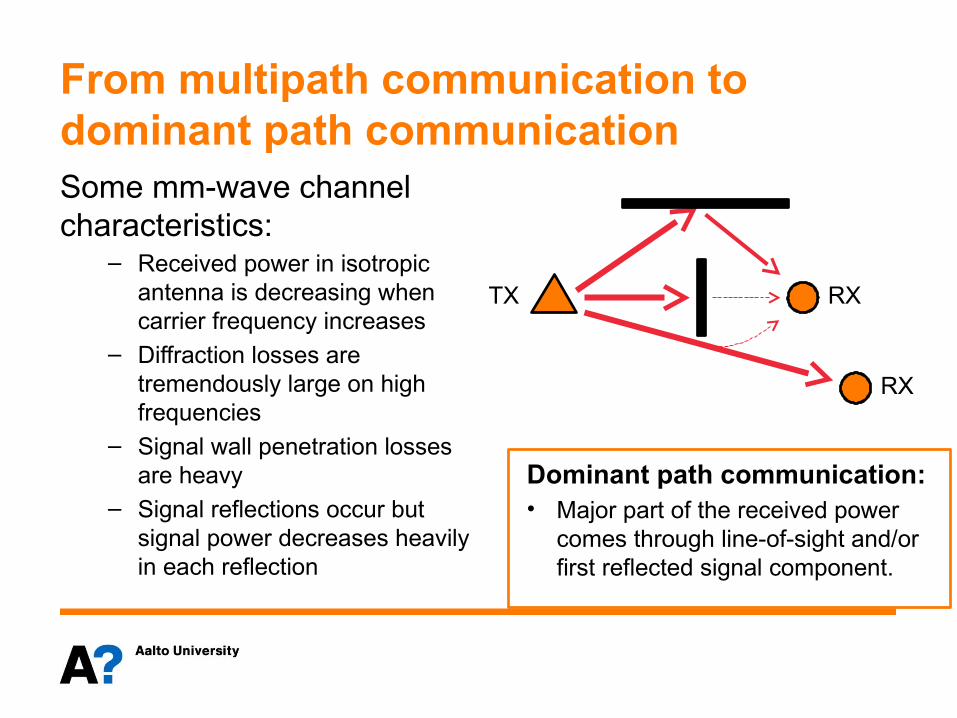
From multipath communication to dominant path communicationSome mm-wave channel characteristics:
– Received power in isotropic antenna is decreasing when carrier frequency increases
– Diffraction losses are tremendously large on high frequencies
– Signal wall penetration losses are heavy
– Signal reflections occur but signal power decreases heavily in each reflection
TX RX
RX
Dominant path communication:• Major part of the received power
comes through line-of-sight and/or first reflected signal component.
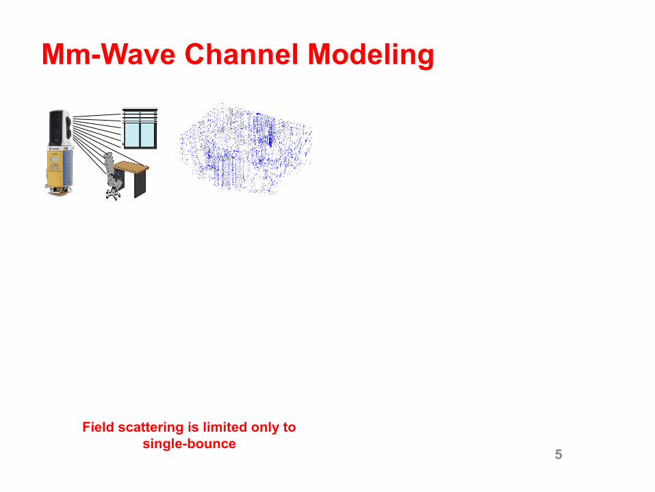
Mm-Wave Channel Modeling
5
Field scattering is limited only to single-bounce
Mm-Wave Channel Modeling
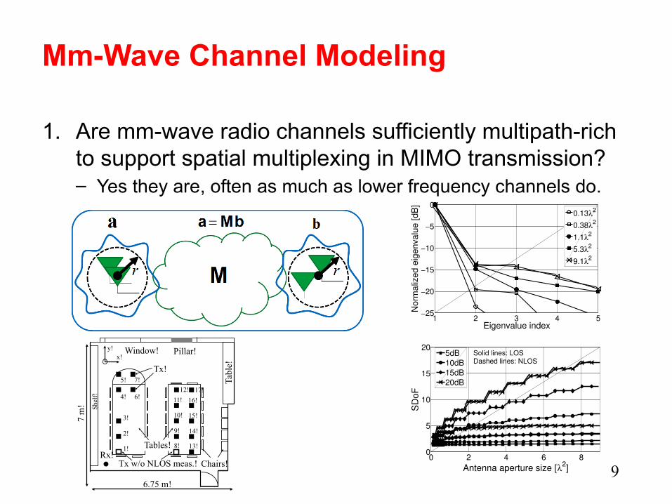
1. Are mm-wave radio channels sufficiently multipath-rich to support spatial multiplexing in MIMO transmission?– Yes they are, often as much as lower frequency channels do.
9
Window! Pillar!
Tables!Rx!
Tx!
Shel
f!
Chairs!
Tabl
e!
7 m
!
6.75 m!
1!
2!
3!
4!
5!
6!
7!
8!
9!
10!
12!
11!
13!
14!
15!
17!
16!
x!y!
Tx w/o NLOS meas.!

Implications from dominant path presumption • Cell shapes
– The cell shapes become quasi-deterministic– The cell edges will be sharp– Coverage areas will be usually defined by surrounding physical
obstacles– Currently used shadow fading model becomes irrelevant
• Coverage vs interference– If cell overlap exists, overheard signals are usually strong. – Shot noise type of interference occurs – unless coordinated
communication is applied.
• Control approaches– Reactive control structures: Based on e.g. UE and eNB
measurements. – Proactive control: Traces and traffic statistics could be used. – Out of band control (<3.5 GHz)?
• Multiantenna systems– Integrated antenna arrays become feasible even in mobile devices– Beamforming/steerable directive antennas provide means to overcome
heavy attenuation losses.– Due to frequent LOS and large BWs the importance of spatial
multiplexing decreases. – Paradigm shift from passive isotropic/sectorized to active directive
radio communication
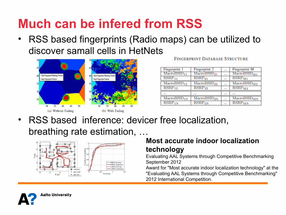
Much can be infered from RSS • RSS based fingerprints (Radio maps) can be utilized to
discover samall cells in HetNets
• RSS based inference: devicer free localization, breathing rate estimation, …
Most accurate indoor localization technology Evaluating AAL Systems through Competitive BenchmarkingSeptember 2012Award for "Most accurate indoor localization technology" at the "Evaluating AAL Systems through Competitive Benchmarking" 2012 International Competition.
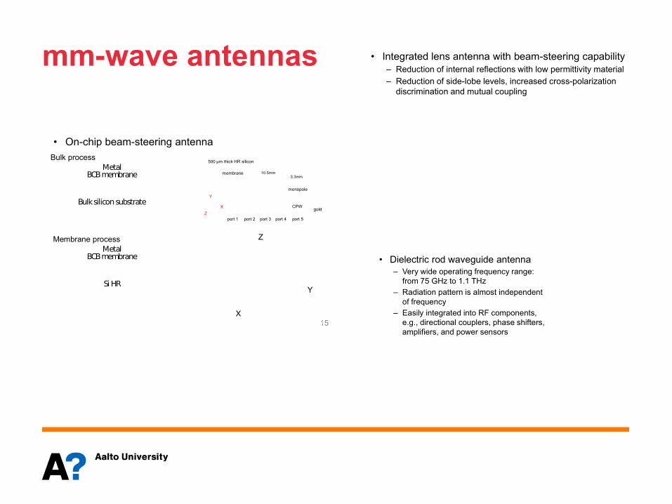
mm-wave antennas
Mm-Wave Antennas• On-chip beam-steering antenna
15
3.3mm
500 µm thick HR silicon
membrane
gold
port 1 port 2 port 3 port 4 port 5
CPWX
Y
Z
10.5mm
monopole
Y
X
Z
Radiation efficiency 84 %
Max gain 3.8 dBi
Bulk silicon substrate
BCB membraneMetal
Bulk process
Membrane process
Si HR
BCB membraneMetal
Mm-Wave Antennas• Integrated lens antenna with beam-steering capability
– Reduction of internal reflections with low permittivity material– Reduction of side-lobe levels, increased cross-polarization
discrimination and mutual coupling
Mm-Wave Antennas• Dielectric rod waveguide antenna
– Very wide operating frequency range: from 75 GHz to 1.1 THz
– Radiation pattern is almost independent of frequency
– Easily integrated into RF components, e.g., directional couplers, phase shifters, amplifiers, and power sensors
II Spectral efficiency
13
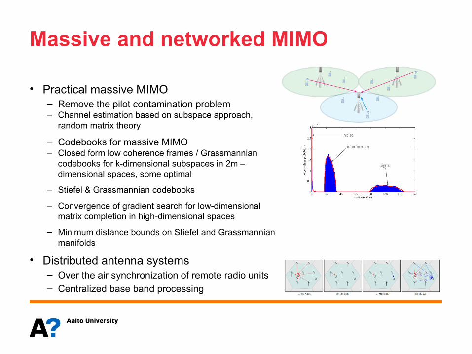
Massive and networked MIMO
• Practical massive MIMO– Remove the pilot contamination problem – Channel estimation based on subspace approach,
random matrix theory
– Codebooks for massive MIMO– Closed form low coherence frames / Grassmannian
codebooks for k-dimensional subspaces in 2m –dimensional spaces, some optimal
– Stiefel & Grassmannian codebooks
– Convergence of gradient search for low-dimensional matrix completion in high-dimensional spaces
– Minimum distance bounds on Stiefel and Grassmannian manifolds
• Distributed antenna systems– Over the air synchronization of remote radio units– Centralized base band processing
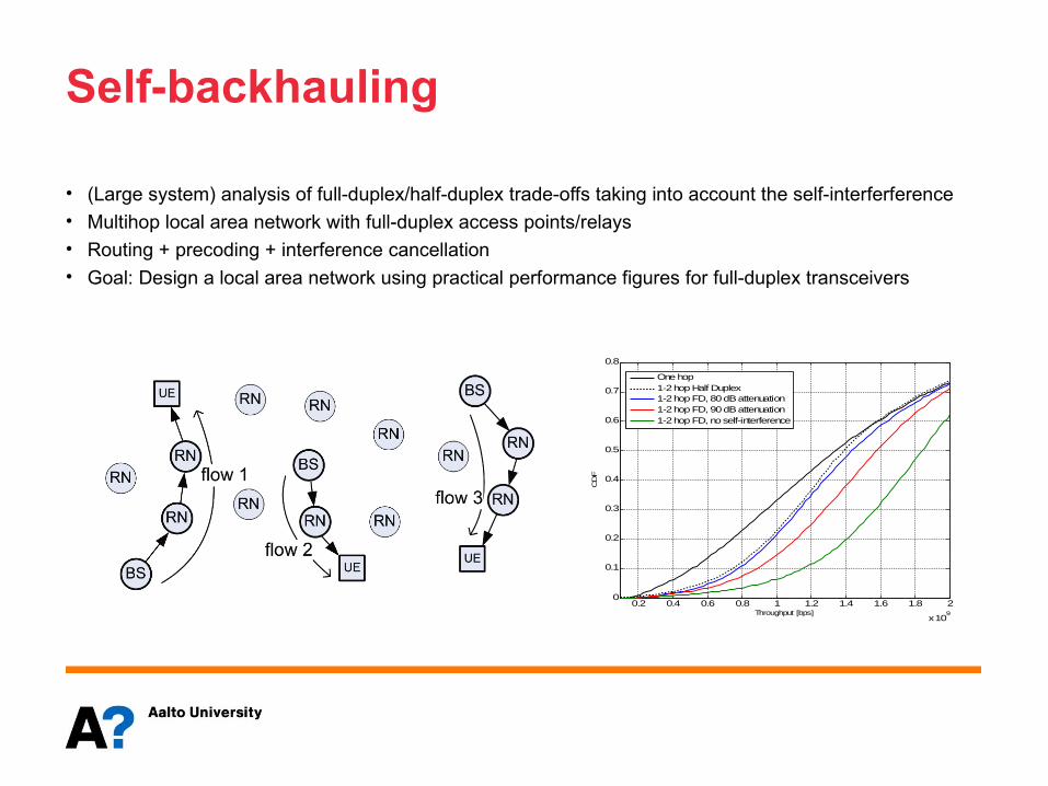
Self-backhauling
• (Large system) analysis of full-duplex/half-duplex trade-offs taking into account the self-interferference• Multihop local area network with full-duplex access points/relays• Routing + precoding + interference cancellation• Goal: Design a local area network using practical performance figures for full-duplex transceivers
0.2 0.4 0.6 0.8 1 1.2 1.4 1.6 1.8 2
x 109
0
0.1
0.2
0.3
0.4
0.5
0.6
0.7
0.8
Throughput [bps]
CD
F
One hop1-2 hop Half Duplex1-2 hop FD, 80 dB attenuation1-2 hop FD, 90 dB attenuation1-2 hop FD, no self-interference
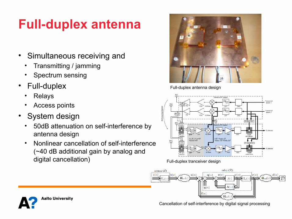
Full-duplex antenna
• Simultaneous receiving and• Transmitting / jamming• Spectrum sensing
• Full-duplex• Relays• Access points
• System design• 50dB attenuation on self-interference by
antenna design• Nonlinear cancellation of self-interference
(~40 dB additional gain by analog and digital cancellation)
Full-duplex antenna design
Full-duplex tranceiver design
Cancellation of self-interference by digital signal processing
III Densification
17
Virtualization
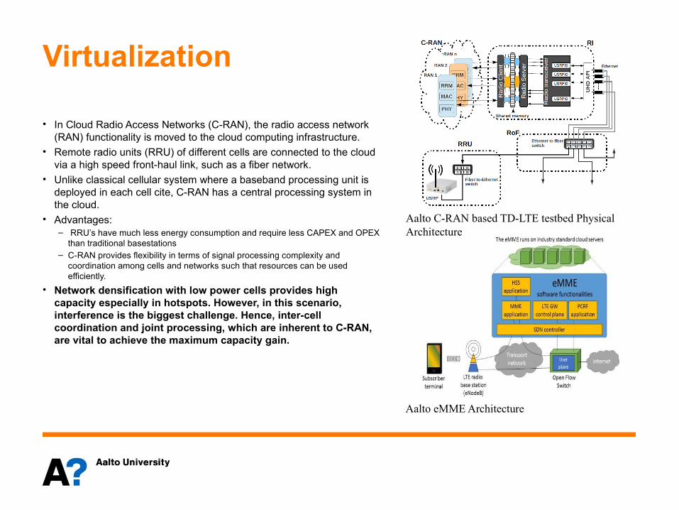
• In Cloud Radio Access Networks (C-RAN), the radio access network (RAN) functionality is moved to the cloud computing infrastructure.
• Remote radio units (RRU) of different cells are connected to the cloud via a high speed front-haul link, such as a fiber network.
• Unlike classical cellular system where a baseband processing unit is deployed in each cell cite, C-RAN has a central processing system in the cloud.
• Advantages:– RRU’s have much less energy consumption and require less CAPEX and OPEX
than traditional basestations – C-RAN provides flexibility in terms of signal processing complexity and
coordination among cells and networks such that resources can be used efficiently.
• Network densification with low power cells provides high capacity especially in hotspots. However, in this scenario, interference is the biggest challenge. Hence, inter-cell coordination and joint processing, which are inherent to C-RAN, are vital to achieve the maximum capacity gain.
Aalto C-RAN based TD-LTE testbed Physical Architecture
Aalto eMME Architecture
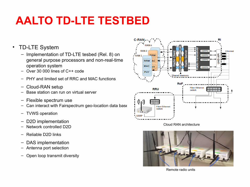
AALTO TD-LTE TESTBED
• TD-LTE System– Implementation of TD-LTE tesbed (Rel. 8) on
general purpose processors and non-real-time operation system
– Over 30 000 lines of C++ code
– PHY and limited set of RRC and MAC functions
– Cloud-RAN setup – Base station can run on virtual server
– Flexible spectrum use– Can interact with Fairspectrum geo-location data base
– TVWS operation
– D2D implementation– Network controlled D2D
– Reliable D2D links
– DAS implementation– Antenna port selection
– Open loop transmit diversity
Cloud RAN architecture
Remote radio units
IV Ultra-reliable communications
20
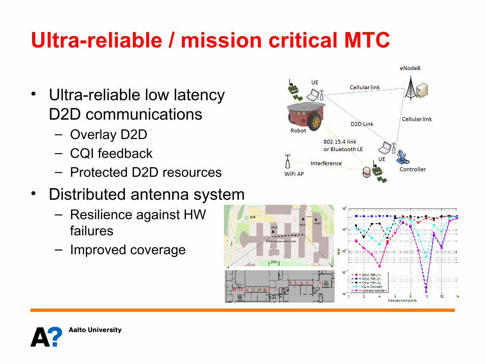
Ultra-reliable / mission critical MTC
• Ultra-reliable low latency D2D communications– Overlay D2D – CQI feedback– Protected D2D resources
• Distributed antenna system– Resilience against HW
failures– Improved coverage
Summary
• 5G requirements imposes many challenges– Capacity– Latency– Reliability
• Enabling technologies– New control architectures– mm-wave– massive and networked MIMO– ultra dense networks– Scalability and flexibility through Cloud technologies