5975 Series Mass Selective Detector Site Preparation Checklist
14
Agilent Technologies Agilent GC, MSD, and ALS Site Preparation Checklist Dimensions and Weight 2 Power Consumption 4 Heat Dissipation 6 Environmental Conditions 7 Gas Selection 8 Gas Supply 10 Other Considerations 12 Exhaust venting requirements for the GC/MSD 12 Basic tools 13 This checklist outlines the space and resource requirements for a GC, MSD, and automatic liquid sampler (ALS) installation. For a successful and timely installation of the instrument, the site must meet these requirements before beginning installation. Necessary supplies (gases, tubing, operating supplies, consumables, and other usage-dependent items such as columns, vials, syringes, and solvents) must also be available. Note that performance verification requires the use of helium carrier gas and, for models using chemical ionization, methane reagent gas. Refer to the Agilent Web site at www.agilent.com/chem for the most up-to-date listing of GC, MSD, and ALS supplies and consumables.
Transcript of 5975 Series Mass Selective Detector Site Preparation Checklist
Agilent GC, MSD, and ALS
Site Preparation Checklist
Dimensions and Weight 2
Power Consumption 4
Heat Dissipation 6
Environmental Conditions 7
Gas Selection 8
Gas Supply 10
Other Considerations 12
Exhaust venting requirements for the GC/MSD 12
Basic tools 13
This checklist outlines the space and resource requirements for a GC, MSD, and automatic liquid sampler (ALS) installation. For a successful and timely installation of the instrument, the site must meet these requirements before beginning installation. Necessary supplies (gases, tubing, operating supplies, consumables, and other usage-dependent items such as columns, vials, syringes, and solvents) must also be available. Note that performance verification requires the use of helium carrier gas and, for models using chemical ionization, methane reagent gas. Refer to the Agilent Web site at www.agilent.com/chem for the most up-to-date listing of GC, MSD, and ALS supplies and consumables.
Agilent Technologies
Agilent GC, MSD, and ALS
Dimensions and Weight
Select the laboratory bench space before the system arrives. Pay special attention to the total height requirements. Avoid bench space with overhanging shelves. See Table 1.
Allow at least 20-cm clearance between back of GC and wall to dissipate air.
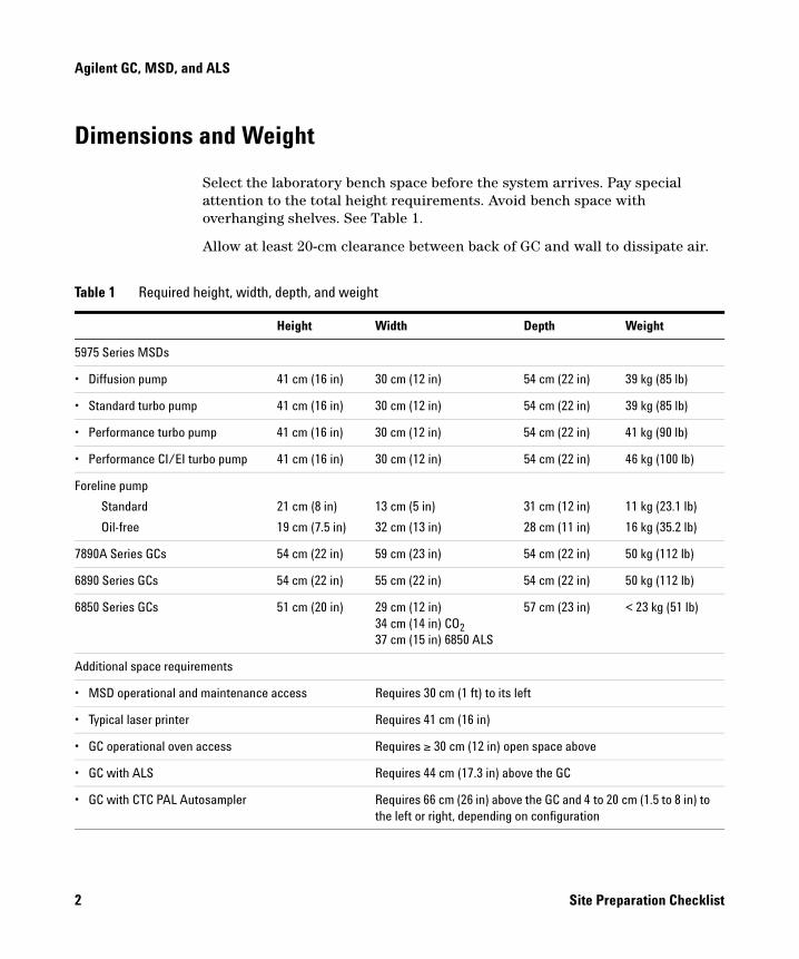
Table 1 Required height, width, depth, and weight
Height Width Depth Weight
5975 Series MSDs
• Diffusion pump 41 cm (16 in) 30 cm (12 in) 54 cm (22 in) 39 kg (85 lb)
• Standard turbo pump 41 cm (16 in) 30 cm (12 in) 54 cm (22 in) 39 kg (85 lb)
• Performance turbo pump 41 cm (16 in) 30 cm (12 in) 54 cm (22 in) 41 kg (90 lb)
• Performance CI/EI turbo pump 41 cm (16 in) 30 cm (12 in) 54 cm (22 in) 46 kg (100 lb)
Foreline pump
Standard
Oil-free
21 cm (8 in)
19 cm (7.5 in)
13 cm (5 in)
32 cm (13 in)
31 cm (12 in)
28 cm (11 in)
11 kg (23.1 lb)
16 kg (35.2 lb)
7890A Series GCs 54 cm (22 in) 59 cm (23 in) 54 cm (22 in) 50 kg (112 lb)
6890 Series GCs 54 cm (22 in) 55 cm (22 in) 54 cm (22 in) 50 kg (112 lb)
6850 Series GCs 51 cm (20 in) 29 cm (12 in)34 cm (14 in) CO237 cm (15 in) 6850 ALS
57 cm (23 in) < 23 kg (51 lb)
Additional space requirements
• MSD operational and maintenance access Requires 30 cm (1 ft) to its left
• Typical laser printer Requires 41 cm (16 in)
• GC operational oven access Requires ≥ 30 cm (12 in) open space above
• GC with ALS Requires 44 cm (17.3 in) above the GC
• GC with CTC PAL Autosampler Requires 66 cm (26 in) above the GC and 4 to 20 cm (1.5 to 8 in) to the left or right, depending on configuration
2 Site Preparation Checklist
Agilent GC, MSD, and ALS
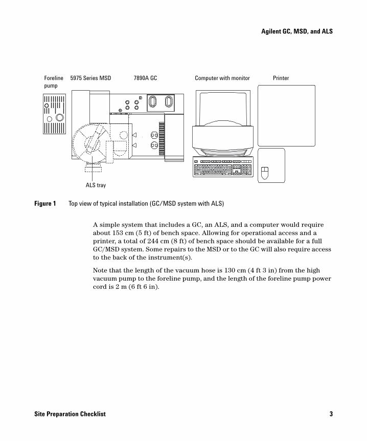
A simple system that includes a GC, an ALS, and a computer would require about 153 cm (5 ft) of bench space. Allowing for operational access and a printer, a total of 244 cm (8 ft) of bench space should be available for a full GC/MSD system. Some repairs to the MSD or to the GC will also require access to the back of the instrument(s).
Note that the length of the vacuum hose is 130 cm (4 ft 3 in) from the high vacuum pump to the foreline pump, and the length of the foreline pump power cord is 2 m (6 ft 6 in).
Figure 1 Top view of typical installation (GC/MSD system with ALS)
Foreline pump
5975 Series MSD 7890A GC Computer with monitor Printer
ALS tray
Site Preparation Checklist 3
Agilent GC, MSD, and ALS
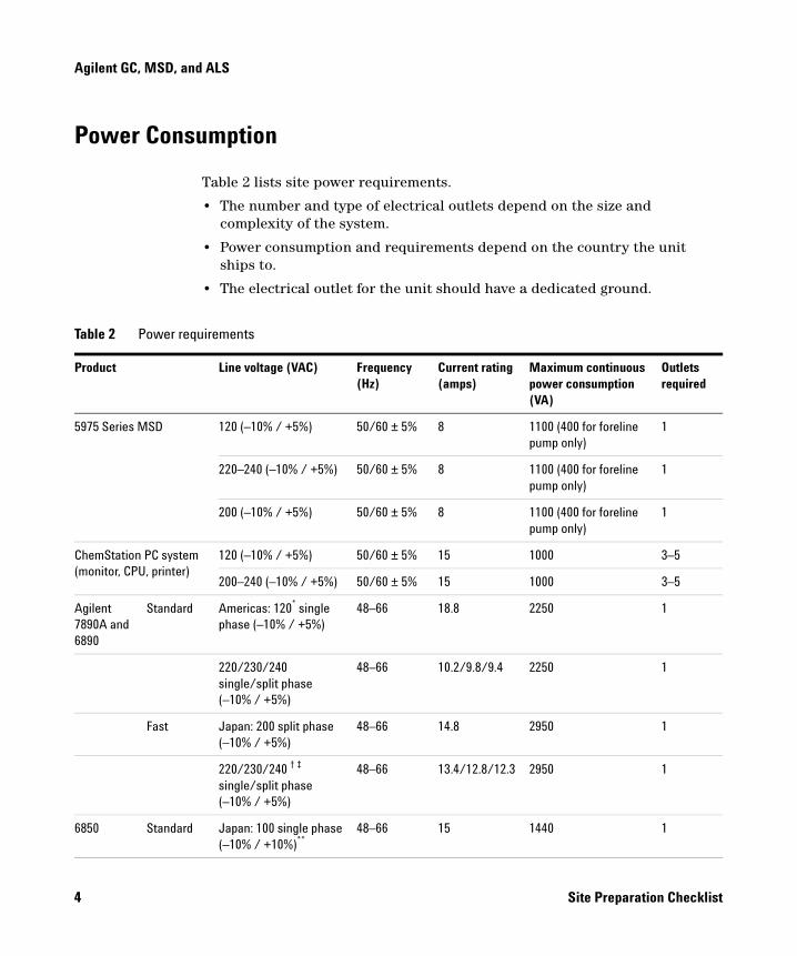
Power Consumption
Table 2 lists site power requirements.
• The number and type of electrical outlets depend on the size and complexity of the system.
• Power consumption and requirements depend on the country the unit ships to.
• The electrical outlet for the unit should have a dedicated ground.
Table 2 Power requirements
Product Line voltage (VAC) Frequency (Hz)
Current rating (amps)
Maximum continuous power consumption (VA)
Outlets required
5975 Series MSD 120 (–10% / +5%) 50/60 ± 5% 8 1100 (400 for foreline pump only)
1
220–240 (–10% / +5%) 50/60 ± 5% 8 1100 (400 for foreline pump only)
1
200 (–10% / +5%) 50/60 ± 5% 8 1100 (400 for foreline pump only)
1
ChemStation PC system (monitor, CPU, printer)
120 (–10% / +5%) 50/60 ± 5% 15 1000 3–5
200–240 (–10% / +5%) 50/60 ± 5% 15 1000 3–5
Agilent 7890A and 6890
Standard Americas: 120* single phase (–10% / +5%)
48–66 18.8 2250 1
220/230/240 single/split phase (–10% / +5%)
48–66 10.2/9.8/9.4 2250 1
Fast Japan: 200 split phase (–10% / +5%)
48–66 14.8 2950 1
220/230/240 † ‡ single/split phase (–10% / +5%)
48–66 13.4/12.8/12.3 2950 1
6850 Standard Japan: 100 single phase (–10% / +10%)**
48–66 15 1440 1
4 Site Preparation Checklist
Agilent GC, MSD, and ALS
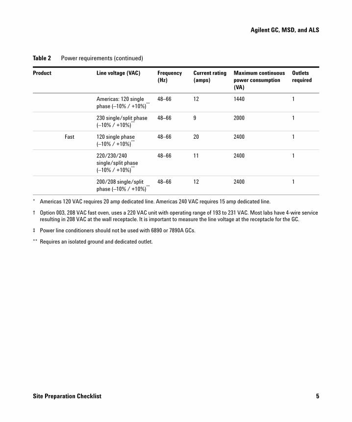
Americas: 120 single phase (–10% / +10%)**
48–66 12 1440 1
230 single/split phase (–10% / +10%)**
48–66 9 2000 1
Fast 120 single phase (–10% / +10%)**
48–66 20 2400 1
220/230/240 single/split phase (–10% / +10%)**
48–66 11 2400 1
200/208 single/split phase (–10% / +10%)**
48–66 12 2400 1
* Americas 120 VAC requires 20 amp dedicated line. Americas 240 VAC requires 15 amp dedicated line.
† Option 003, 208 VAC fast oven, uses a 220 VAC unit with operating range of 193 to 231 VAC. Most labs have 4-wire service resulting in 208 VAC at the wall receptacle. It is important to measure the line voltage at the receptacle for the GC.
‡ Power line conditioners should not be used with 6890 or 7890A GCs.
** Requires an isolated ground and dedicated outlet.
Table 2 Power requirements (continued)
Product Line voltage (VAC) Frequency (Hz)
Current rating (amps)
Maximum continuous power consumption (VA)
Outlets required
Site Preparation Checklist 5
Agilent GC, MSD, and ALS
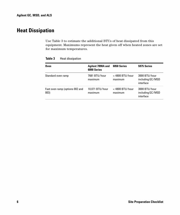
Heat Dissipation
Use Table 3 to estimate the additional BTUs of heat dissipated from this equipment. Maximums represent the heat given off when heated zones are set for maximum temperatures.
Table 3 Heat dissipation
Oven Agilent 7890A and 6890 Series
6850 Series 5975 Series
Standard oven ramp 7681 BTU/hour maximum
< 4800 BTU/hour maximum
3000 BTU/hour including GC/MSD interface
Fast oven ramp (options 002 and 003)
10,071 BTU/hour maximum
< 4800 BTU/hour maximum
3000 BTU/hour including GC/MSD interface
6 Site Preparation Checklist
Agilent GC, MSD, and ALS
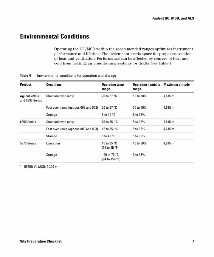
Environmental Conditions
Operating the GC/MSD within the recommended ranges optimizes instrument performance and lifetime. The instrument needs space for proper convection of heat and ventilation. Performance can be affected by sources of heat and cold from heating, air conditioning systems, or drafts. See Table 4.
Table 4 Environmental conditions for operation and storage
Product Conditions Operating temp range
Operating humidity range
Maximum altitude
Agilent 7890A and 6890 Series
Standard oven ramp 20 to 27 °C 50 to 60% 4,615 m
Fast oven ramp (options 002 and 003) 20 to 27 °C 50 to 60% 4,615 m
Storage 5 to 40 °C 5 to 95%
6850 Series Standard oven ramp 15 to 35 °C 5 to 95% 4,615 m
Fast oven ramp (options 002 and 003) 15 to 35 °C 5 to 95% 4,615 m
Storage 5 to 40 °C 5 to 95%
5975 Series Operation 15 to 35 °C(59 to 95 °F)
40 to 80% 4,615 m*
Storage –20 to 70 °C (–4 to 158 °F)
0 to 95%
* 5975B VL MSD: 2,300 m
Site Preparation Checklist 7
Agilent GC, MSD, and ALS
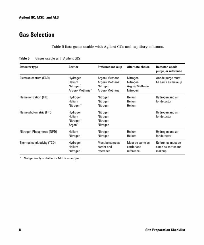
Gas Selection
Table 5 lists gases usable with Agilent GCs and capillary columns.
Table 5 Gases usable with Agilent GCs
Detector type Carrier Preferred makeup Alternate choice Detector, anode purge, or reference
Electron capture (ECD) HydrogenHeliumNitrogen*
Argon/Methane*
Argon/MethaneArgon/MethaneNitrogenArgon/Methane
NitrogenNitrogenArgon/MethaneNitrogen
Anode purge must be same as makeup
Flame ionization (FID) HydrogenHeliumNitrogen*
NitrogenNitrogenNitrogen
HeliumHeliumHelium
Hydrogen and air for detector
Flame photometric (FPD) HydrogenHeliumNitrogen*Argon*
NitrogenNitrogenNitrogenNitrogen
Hydrogen and air for detector
Nitrogen-Phosphorus (NPD) HeliumNitrogen*
NitrogenNitrogen
HeliumHelium
Hydrogen and air for detector
Thermal conductivity (TCD) HydrogenHeliumNitrogen*
Must be same as carrier and reference
Must be same as carrier and reference
Reference must be same as carrier and makeup
* Not generally suitable for MSD carrier gas.
8 Site Preparation Checklist
Agilent GC, MSD, and ALS
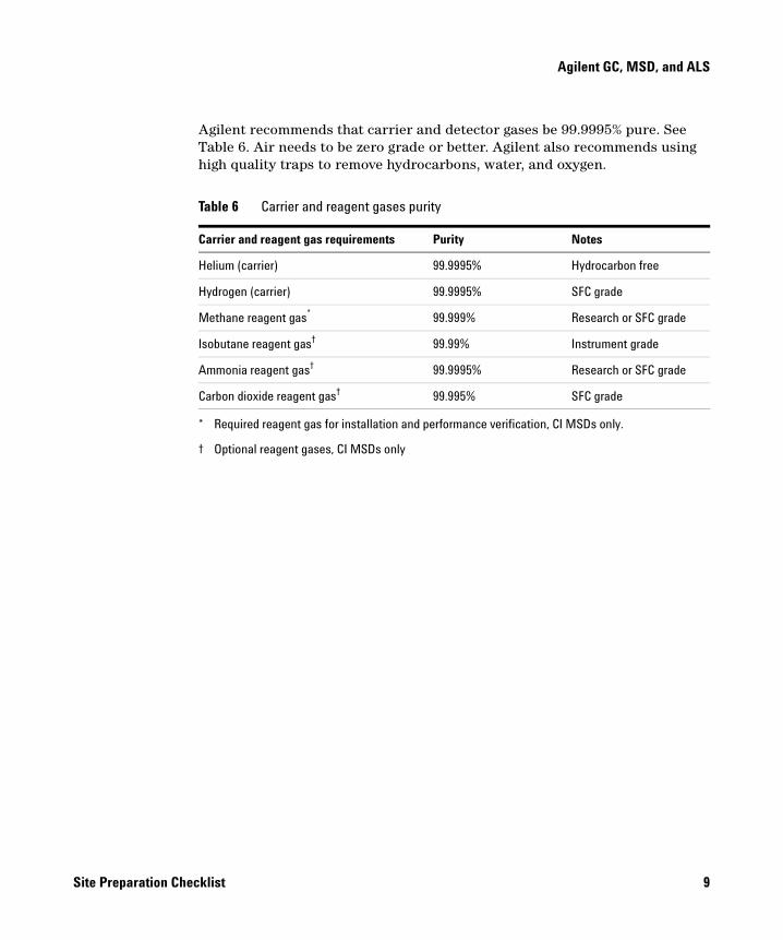
Agilent recommends that carrier and detector gases be 99.9995% pure. See Table 6. Air needs to be zero grade or better. Agilent also recommends using high quality traps to remove hydrocarbons, water, and oxygen.
Table 6 Carrier and reagent gases purity
Carrier and reagent gas requirements Purity Notes
Helium (carrier) 99.9995% Hydrocarbon free
Hydrogen (carrier) 99.9995% SFC grade
Methane reagent gas*
* Required reagent gas for installation and performance verification, CI MSDs only.
99.999% Research or SFC grade
Isobutane reagent gas†
† Optional reagent gases, CI MSDs only
99.99% Instrument grade
Ammonia reagent gas† 99.9995% Research or SFC grade
Carbon dioxide reagent gas† 99.995% SFC grade
Site Preparation Checklist 9
Agilent GC, MSD, and ALS
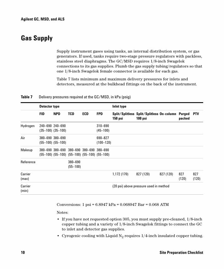
Gas Supply
Supply instrument gases using tanks, an internal distribution system, or gas generators. If used, tanks require two-stage pressure regulators with packless, stainless steel diaphragms. The GC/MSD requires 1/8-inch Swagelok connections to its gas supplies. Plumb the gas supply tubing/regulators so that one 1/8-inch Swagelok female connector is available for each gas.
Table 7 lists minimum and maximum delivery pressures for inlets and detectors, measured at the bulkhead fittings on the back of the instrument.
Conversions: 1 psi = 6.8947 kPa = 0.068947 Bar = 0.068 ATM
Notes:
• If you have not requested option 305, you must supply pre-cleaned, 1/8-inch copper tubing and a variety of 1/8-inch Swagelok fittings to connect the GC to inlet and detector gas supplies.
• Cyrogenic cooling with Liquid N2 requires 1/4-inch insulated copper tubing.
Table 7 Delivery pressures required at the GC/MSD, in kPa (psig)
Detector type Inlet type
FID NPD TCD ECD FPD Split/Splitless 150 psi
Split/Splitless 100 psi
On-column Purged packed
PTV
Hydrogen 240–690 (35–100)
240–690 (35–100)
310–690 (45–100)
Air 380–690 (55–100)
380–690 (55–100)
690–827 (100–120)
Makeup 380–690 (55–100)
380–690 (55–100)
380–690 (55–100)
380–690 (55–100)
380–690 (55–100)
Reference 380–690 (55–100)
Carrier (max)
1,172 (170) 827 (120) 827 (120) 827 (120)
827 (120)
Carrier (min)
(20 psi) above pressure used in method
10 Site Preparation Checklist
Agilent GC, MSD, and ALS
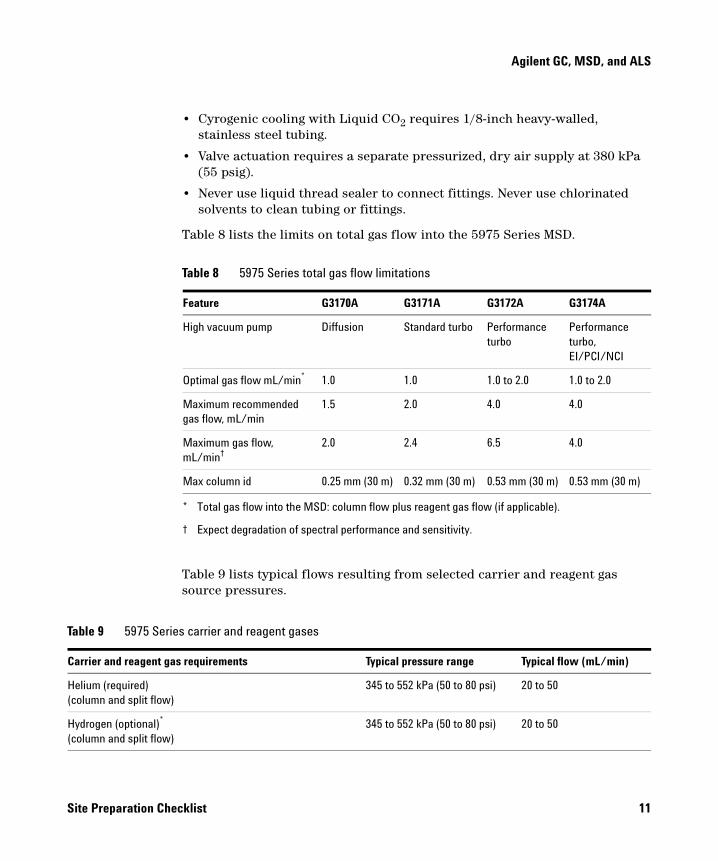
• Cyrogenic cooling with Liquid CO2 requires 1/8-inch heavy-walled, stainless steel tubing.
• Valve actuation requires a separate pressurized, dry air supply at 380 kPa (55 psig).
• Never use liquid thread sealer to connect fittings. Never use chlorinated solvents to clean tubing or fittings.
Table 8 lists the limits on total gas flow into the 5975 Series MSD.
Table 9 lists typical flows resulting from selected carrier and reagent gas source pressures.
Table 8 5975 Series total gas flow limitations
Feature G3170A G3171A G3172A G3174A
High vacuum pump Diffusion Standard turbo Performance turbo
Performance turbo, EI/PCI/NCI
Optimal gas flow mL/min*
* Total gas flow into the MSD: column flow plus reagent gas flow (if applicable).
1.0 1.0 1.0 to 2.0 1.0 to 2.0
Maximum recommended gas flow, mL/min
1.5 2.0 4.0 4.0
Maximum gas flow, mL/min†
† Expect degradation of spectral performance and sensitivity.
2.0 2.4 6.5 4.0
Max column id 0.25 mm (30 m) 0.32 mm (30 m) 0.53 mm (30 m) 0.53 mm (30 m)
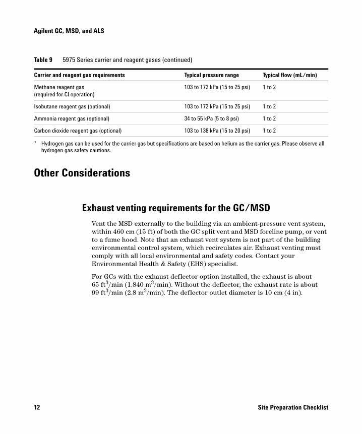
Table 9 5975 Series carrier and reagent gases
Carrier and reagent gas requirements Typical pressure range Typical flow (mL/min)
Helium (required)(column and split flow)
345 to 552 kPa (50 to 80 psi) 20 to 50
Hydrogen (optional)* (column and split flow)
345 to 552 kPa (50 to 80 psi) 20 to 50
Site Preparation Checklist 11
Agilent GC, MSD, and ALS
Other Considerations
Exhaust venting requirements for the GC/MSD
Vent the MSD externally to the building via an ambient-pressure vent system, within 460 cm (15 ft) of both the GC split vent and MSD foreline pump, or vent to a fume hood. Note that an exhaust vent system is not part of the building environmental control system, which recirculates air. Exhaust venting must comply with all local environmental and safety codes. Contact your Environmental Health & Safety (EHS) specialist.
For GCs with the exhaust deflector option installed, the exhaust is about 65 ft3/min (1.840 m3/min). Without the deflector, the exhaust rate is about 99 ft3/min (2.8 m3/min). The deflector outlet diameter is 10 cm (4 in).
Methane reagent gas(required for CI operation)
103 to 172 kPa (15 to 25 psi) 1 to 2
Isobutane reagent gas (optional) 103 to 172 kPa (15 to 25 psi) 1 to 2
Ammonia reagent gas (optional) 34 to 55 kPa (5 to 8 psi) 1 to 2
Carbon dioxide reagent gas (optional) 103 to 138 kPa (15 to 20 psi) 1 to 2
* Hydrogen gas can be used for the carrier gas but specifications are based on helium as the carrier gas. Please observe all hydrogen gas safety cautions.
Table 9 5975 Series carrier and reagent gases (continued)
Carrier and reagent gas requirements Typical pressure range Typical flow (mL/min)
12 Site Preparation Checklist
Agilent GC, MSD, and ALS
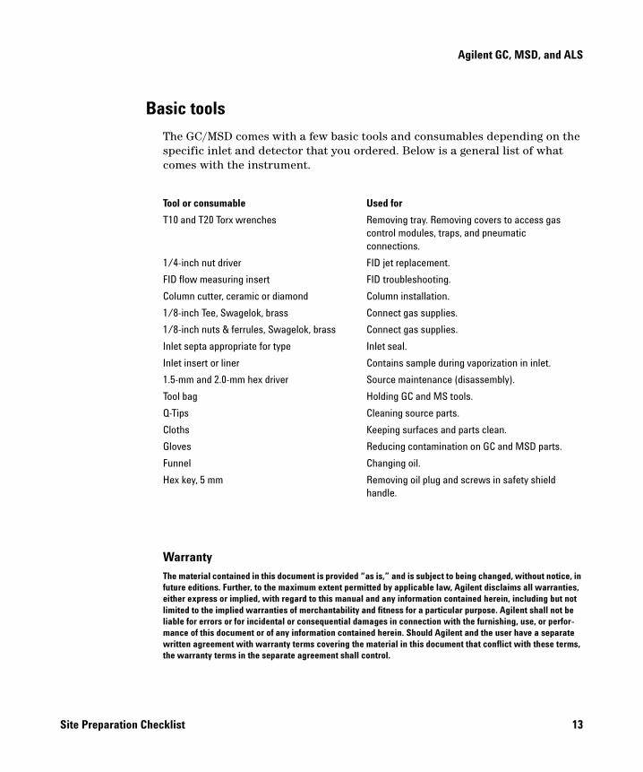
Basic tools
The GC/MSD comes with a few basic tools and consumables depending on the specific inlet and detector that you ordered. Below is a general list of what comes with the instrument.
WarrantyThe material contained in this document is provided “as is,” and is subject to being changed, without notice, in future editions. Further, to the maximum extent permitted by applicable law, Agilent disclaims all warranties, either express or implied, with regard to this manual and any information contained herein, including but not limited to the implied warranties of merchantability and fitness for a particular purpose. Agilent shall not be liable for errors or for incidental or consequential damages in connection with the furnishing, use, or perfor-mance of this document or of any information contained herein. Should Agilent and the user have a separate written agreement with warranty terms covering the material in this document that conflict with these terms, the warranty terms in the separate agreement shall control.
Tool or consumable Used for
T10 and T20 Torx wrenches Removing tray. Removing covers to access gas control modules, traps, and pneumatic connections.
1/4-inch nut driver FID jet replacement.
FID flow measuring insert FID troubleshooting.
Column cutter, ceramic or diamond Column installation.
1/8-inch Tee, Swagelok, brass Connect gas supplies.
1/8-inch nuts & ferrules, Swagelok, brass Connect gas supplies.
Inlet septa appropriate for type Inlet seal.
Inlet insert or liner Contains sample during vaporization in inlet.
1.5-mm and 2.0-mm hex driver Source maintenance (disassembly).
Tool bag Holding GC and MS tools.
Q-Tips Cleaning source parts.
Cloths Keeping surfaces and parts clean.
Gloves Reducing contamination on GC and MSD parts.
Funnel Changing oil.
Hex key, 5 mm Removing oil plug and screws in safety shield handle.
Site Preparation Checklist 13
Agilent Technologies
First Edition March 2007
This information is subject to change without notice.
© Agilent Technologies, Inc. 2007
Printed in U.S.A., March 2007
G3170-90025