5801H0017---R02-B00- en ES915-ES919 · ES915 ES919 NC WHITH BELT DRIVEN "C" AXIS UNIT ES919 NC...
98
Installation, Operation and Maintenance Manual 5801H0017 Revision 02 ELECTRO-SPINDLES for automatic tool changing HSD S.p.a. TECHNOLOGICAL EQUIPMENT FOR AUTOMATION Via della Meccanica 16 Loc. Chiusa di Ginestreto 61100 PESARO (ITALIA) Tel. (+39)0721.439.612 Fax(+39)0721.441.606 E-mail [email protected] Web: www.hsd.it ES915 ES919 NC WHITH BELT DRIVEN "C" AXIS UNIT ES919 NC ES919 NL ES919 L NC ES919 L NL
Transcript of 5801H0017---R02-B00- en ES915-ES919 · ES915 ES919 NC WHITH BELT DRIVEN "C" AXIS UNIT ES919 NC...

Installation, Operation and Maintenance Manual5801H0017Revision 02
ELECTRO-SPINDLESfor automatic tool changing
HSD S.p.a.TECHNOLOGICAL EQUIPMENT FOR AUTOMATION
Via della Meccanica 16Loc. Chiusa di Ginestreto61100 PESARO (ITALIA)
Tel. (+39)0721.439.612Fax(+39)0721.441.606
E-mail [email protected]: www.hsd.it
ES915ES919 NC
WHITH BELT DRIVEN "C" AXIS UNIT
ES919 NC ES919 NL
ES919 L NC ES919 L NL

______HSD Technological equipment for Automation _____________________________________
5801H0017 Rev. 02 __________________________________________________________ 2/98
TABLE OF CONTENTS
§ 1 DOCUMENTS DELIVERED WITH THE ELECTRO-SPINDLE......................................... 5
§ 2 DOCUMENT INFORMATION ........................................................................................... 5
§ 3 CUSTOMER ASSISTANCE SERVICE ............................................................................. 5
§ 4 TERMS OF WARRANTY.................................................................................................. 6
§ 5 WARNINGS AND SAFETY PRECAUTIONS.................................................................... 75.1 Distribution of this manual .................................................................................................. 75.2 General safety symbols ....................................................................................................... 75.3 Risks associated with the electro-spindle .......................................................................... 85.4 Risks associated with improper use and handling ............................................................ 85.5 Risks specific to maintenance............................................................................................. 9
§ 6 GENERAL INFORMATION............................................................................................... 96.1 Proper use of the product .................................................................................................... 96.2 Identification of manufacturer and part ............................................................................ 106.3 Description of the main parts of the electro-spindle........................................................ 116.4 Glossary.............................................................................................................................. 12
§ 7 TECHNICAL SPECIFICATIONS..................................................................................... 137.1 Available models ................................................................................................................ 13
7.1.1 ES915 / ES915 L ........................................................................................................ 137.1.2 ES919 / ES919 L ........................................................................................................ 13
7.2 Technical specifications of ES915 .................................................................................... 147.2.1 Overall dimensions of ES915 ........................................................................................ 147.2.2 Specifications and performance of ES915 2 Pole, 3.8 kW units .................................... 157.2.3 Specifications and performance of ES915 4 Pole, 5 kW units ....................................... 16
7.3 Technical specifications of ES915 L ................................................................................. 177.3.1 Overall dimensions of ES915 L HSK F63 Long Nose.................................................. 177.3.2 Specifications and performance of ES915 L 4 Pole, 7.5 kW units ................................. 18
7.4 Technical specifications of ES919 .................................................................................... 197.4.1 Overall dimensions of ES919 ISO30 Short Nose .......................................................... 197.4.2 Overall dimensions of ES919 ISO30 Long Nose ........................................................... 207.4.3 Overall dimensions of ES919 HSK F63 Short Nose ...................................................... 217.4.4 Overall dimensions of ES919 HSK F63 Long Nose....................................................... 227.4.5 Specifications and performance of ES919 2 Pole, 7 kW units ....................................... 237.4.6 Specifications and performance of ES919 2 Pole, 8 kW units ....................................... 247.4.7 Specifications and performance of ES919 4 Pole, 5.5 kW units .................................... 257.4.8 Specifications and performance of ES919 4 Pole, 7.5 kW units .................................... 26
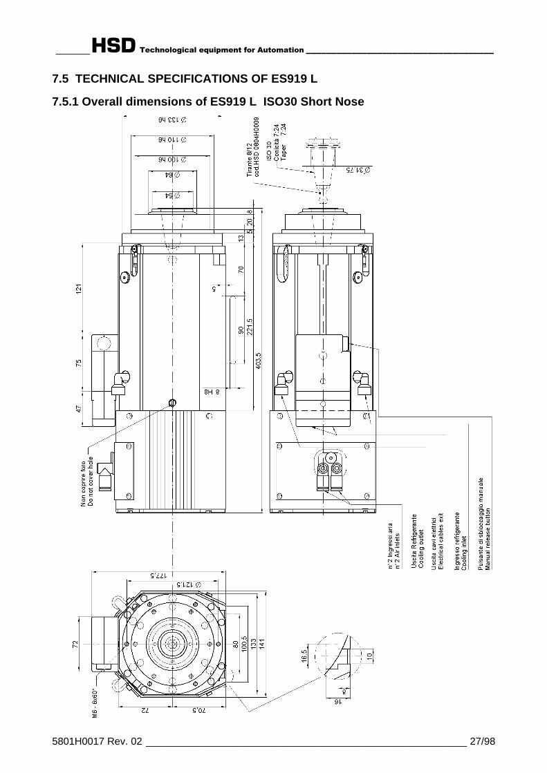
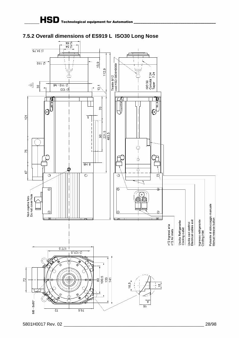
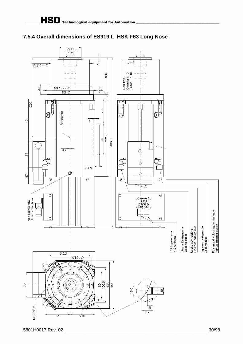
7.5 Technical specifications of ES919 L ................................................................................. 277.5.1 Overall dimensions of ES919 L ISO30 Short Nose ...................................................... 277.5.2 Overall dimensions of ES919 L ISO30 Long Nose ....................................................... 287.5.3 Overall dimensions of ES919 L HSK F63 Short Nose .................................................. 297.5.4 Overall dimensions of ES919 L HSK F63 Long Nose................................................... 307.5.5 Specifications and performance of ES919 L 4 Pole, 12 kW units ................................. 31
7.6 Technical specifications of Belt driven C axis unit.......................................................... 327.6.1 Overall dimensions of ES919 ISO30 Short Nose with belt driven C Axis unit ................ 327.6.2 Overall dimensions of gear units ................................................................................... 337.6.3 Technical specifications for belt driven C axis unit ........................................................ 34
7.7 Technical specifications of components.......................................................................... 357.7.1 Bearings........................................................................................................................ 357.7.2 Tool holder locking and release device ......................................................................... 357.7.3 Automatic cleaning of the tool holder and internal pressurization .................................. 367.7.4 Proximity sensors.......................................................................................................... 36

______HSD Technological equipment for Automation _____________________________________
5801H0017 Rev. 02 __________________________________________________________ 3/98
7.7.5 Tool release button ....................................................................................................... 367.7.6 Thermal switch.............................................................................................................. 377.7.7 Cooling fan.................................................................................................................... 37
§ 8 TRANSPORT AND MOVING.......................................................................................... 388.1 Storage................................................................................................................................ 388.2 Lifting the electro-spindle in its crate ............................................................................... 38
§ 9 INSTALLATION .............................................................................................................. 409.1 First Check.......................................................................................................................... 409.2 Preparation of the equipment required for installation on site ....................................... 409.3 Mechanical installation ...................................................................................................... 40
9.3.1 The supporting surface ................................................................................................. 409.3.2 Positioning the electro-spindle ...................................................................................... 409.3.3 Mechanical fixing of the electro-spindle......................................................................... 419.3.4 Threaded service holes................................................................................................. 42
9.4 Compressed air connections............................................................................................. 439.4.1 Compressed air unions ................................................................................................. 439.4.2 Functional diagram of electro-spindle compressed air connections............................... 44
9.5 Cooling circuit .................................................................................................................... 459.5.1 Cooler specifications ..................................................................................................... 45
9.6 Electrical connections........................................................................................................ 469.6.1 Connectors ................................................................................................................... 469.6.2 Pin layout of fixed signals connector - ISO 30 version................................................... 469.6.3 Pin layout of fixed signals connector - HSK F63 version ............................................... 479.6.4 Pin layout of fixed power connector............................................................................... 479.6.5 Tool holder release system electrical wiring diagram for electro-spindles not controlled by
CNC.............................................................................................................................. 489.6.6 Configurable power terminals (optional) ........................................................................ 49
§ 10 GENERAL CHECKS AFTER INSTALLATION AND DURING START-UP.................. 5010.1 Checking the electro-spindle before start-up ................................................................. 5010.2 Checking the electro-spindle on first start-up................................................................ 51
§ 11 OPERATING THE ELECTRO-SPINDLE ...................................................................... 5211.1 Climatic conditions .......................................................................................................... 5211.2 Running in......................................................................................................................... 5211.3 Warming up....................................................................................................................... 5211.4 Selecting the tool holder and tool ................................................................................... 53
11.4.1 ISO 30 tool holders ..................................................................................................... 5311.4.2 HSK F63 tool holders .................................................................................................. 5411.4.3 General safety precautions for tool holders ................................................................. 5511.4.4 Choosing tools ............................................................................................................ 56
11.5 Speed limitations.............................................................................................................. 5711.5.1 Content of graphs ....................................................................................................... 5711.5.2 Reading the graphs..................................................................................................... 5711.5.3 ES915 ISO30............................................................................................................. 5811.5.4 ES919 ISO30 Short Nose , ES919 L ISO30 Short Nose ...................................... 5911.5.5 ES919 ISO30 Long Nose , ES919 L ISO30 Long Nose........................................ 6011.5.6 ES919 HSK F63 Short Nose , ES919 L HSK F63 Short Nose.............................. 6111.5.7 ES919 HSK F63 Long Nose , ES919 L HSK F63 Long Nose............................... 62
11.6 Sensor functioning........................................................................................................... 6311.6.1 ISO 30 versions .......................................................................................................... 6311.6.2 HSK F63 versions ....................................................................................................... 64
11.7 Thermal switch ................................................................................................................. 65
§ 12 MAINTENANCE............................................................................................................ 6612.1 Scheduled maintenance................................................................................................... 67
12.1.1 Checking the cleanliness of the tool holder cone and of the spindle shaft tool housing 67

______HSD Technological equipment for Automation _____________________________________
5801H0017 Rev. 02 __________________________________________________________ 4/98
12.1.2 Cleaning the tool holder cone...................................................................................... 6912.1.3 Protecting the spindle shaft's conical housing ............................................................. 6912.1.4 Lubricating HSK fingers .............................................................................................. 7012.1.5 Bearings...................................................................................................................... 70
12.2 Replacing parts................................................................................................................. 7112.2.1 Changing the spindle shaft kit ..................................................................................... 7212.2.2 Replacing the cooling fan............................................................................................ 7412.2.3 Replacing the tool change push-button ....................................................................... 7412.2.4 Replacing sensors S1, S2, S3 and S4......................................................................... 75
12.2.4.1 Wiring of sensors in ISO 30 versions...............................................................................7512.2.4.2 Wiring of sensors in HSK versions...................................................................................7512.2.4.3 Accessing the sensors .....................................................................................................7612.2.4.4 Location of sensors ..........................................................................................................7612.2.4.5 The sensor assembly .......................................................................................................7712.2.4.6 Replacing a sensor assembly ..........................................................................................7712.2.4.7 Calibrating sensors S1, S2, and S3 on ISO 30 electro-spindles .....................................7812.2.4.8 Calibrating sensors S1, S2, S3 and S4 on HSK F63 electro-spindles ............................78
12.2.4.8.1 Procedure for S1 ..............................................................................................7812.2.4.8.2 Procedure for S2 ..............................................................................................7812.2.4.8.3 Procedure for S3 ..............................................................................................7912.2.4.8.4 Procedure for S4 ..............................................................................................79
12.2.4.9 Gauge and shim kit for calibrating S1 and S4 sensors on HSK F63 electro-spindles(HSD code 3811H0110).......................................................................................................80
12.2.4.10 Calibrating sensors S1 and S4 on F63 HSK electro-spindles using the 3811H0110 kit8012.2.4.10.1 Procedure for S1 ............................................................................................8112.2.4.10.2 Procedure for S4 ............................................................................................81
12.2.5 Replacing the cylinder assembly ................................................................................. 82
§ 13 ACCESSORIES AND OPTIONS .................................................................................. 8513.1 "Spindle shaft stopped" sensor S3 ................................................................................. 8513.2 Bearing temperature sensor ............................................................................................ 85
13.2.1 Installing the bearing temperature sensor ................................................................... 8613.2.2 Characteristic curve of the temperature sensor referred to 1 mA............................... 86
13.3 “C” axis unit...................................................................................................................... 8713.3.1 Belt driven “C” axis unit ............................................................................................... 8713.3.2 Gear driven “C” axis unit ............................................................................................. 8713.3.3 SC sensor for the belt driven “C” axis unit ................................................................... 8813.3.4 Replacing and calibrating the SC sensor in belt drive versions.................................... 89
13.4 Forced air cooling ............................................................................................................ 9113.4.1 Installing the forced air cooling kit ............................................................................... 91
§ 14 TROUBLE SHOOTING................................................................................................. 92
§ 15 SPARE PARTS LIST .................................................................................................... 96
§ 16 DISPOSING OF THE ELECTRO-SPINDLE.................................................................. 97

______HSD Technological equipment for Automation _____________________________________
5801H0017 Rev. 02 __________________________________________________________ 5/98
§ 1 DOCUMENTS DELIVERED WITH THE ELECTRO-SPINDLE
The following documents are delivered with the electro-spindle:• this manual containing the safety warnings and instructions for installation, operation and
maintenance• a series of other documents including:
1. The Manufacturer's Declaration of conformity to attachment IIB of Directive 98/37/CE2. Attachments containing information on special parts of the electro-spindle. All suchattachments must be consulted in conjunction with the main document to which they refer inorder to avoid missing important information.
Make sure that all the above documents are delivered with the electro-spindle. If any are missing, ask HSD S.p.a. for a replacement copy.
§ 2 DOCUMENT INFORMATION
This manual has been written by the Electro-spindle department of the Technical Office at HSDS.p.a. for use by all the installers, operators and service engineers who work with the electro-spindle.
ISSUED BY CODE REVISION APPROVED BY
HSD S.p.a.Via della Meccanica 16Loc. Chiusa di Ginestreto61100 PESARO (ITALIA)
5801H0017 02 UTE 005 / 03
Record of updatesRevision Added § Deleted § Changed §
00 First issue First issue First issue01 General revision General revision General revision02 ES 915 L HSK F63 Long Nose ---- Overall dimensions of ES 919 L HSK F63 Long Nose
This manual is delivered as an essential part of the electro-spindle and at the time of revision wasthe most up to date documentation on the product.
§ 3 CUSTOMER ASSISTANCE SERVICE
HSD HSD HSDVia della Meccanica 1661100 PESARO (ITALIA)Loc. Chiusa di GinestretoTel. (+39)0721.439.638Fax (+39)0721.441.606E-mail [email protected] www.hsd-hitec.com
HSD Deutschland GmbHBrückenstrasse 2D-73333 GingenTel. +49(0)7162 / 9323436Fax +49(0)7162 / 9323439
HSD USA Inc.3764 SW, 30th AvenueHollywood, Florida 33312 USAPhone no. (+1) 954 587 1991Fax (+1) 954 587 8338E-mail [email protected] www.hsdusa.com

______HSD Technological equipment for Automation _____________________________________
5801H0017 Rev. 02 __________________________________________________________ 6/98
§ 4 TERMS OF WARRANTY
HSD S.p.a. guarantees that this electro-spindle has been QC passed in testing in the factory. HSDS.p.a. accepts responsibility only for defects in electrical and mechanical parts. The warranty doesnot cover defects caused by the normal use of parts subject to continuous or rapid wear (e.g.seals, belts, bearings, etc.). In particular HSD S.p.a. offers no guarantee as to the duration ofbearings, since bearing wear depends on various factors including: tool balancing precision, typeof machining operation, impacts and/or mechanical stress in excess of the manufacturer’s declaredlimits.
HSD S.p.a. declines all responsibility for non-compliance of the electro-spindle caused by failure tofollow the precautions and instructions given in this manual or by improper use or handling of theelectro-spindle. The customer has the right to replacement of all parts shown to be defective,unless the said defects are caused by unauthorized tampering, including the fitting of non-originalHSD spare parts and/or the replacement of parts not described or authorized in this manual unlessauthorized beforehand and in writing by HSD S.p.A..In no case shall HSD S.p.A. or its suppliers accept any responsibility for damage (includingdamage to the unit, damage incurred for lost production and income, down-time in manufacturing,loss of information or other economic losses) deriving from the use of HSD products, even if HSDhas been advised of such risks in advance.
The warranty becomes automatically null and void if the customer fails to notify HSD S.p.A. inwriting of any faults found in the electro-spindle within 15 days of their occurrence. The warrantylikewise becomes null and void if the customer fails to permit the seller to perform all necessarychecks and tests, and if, when the seller requests the return of a defective part, the customer failsto do so within two weeks of the request.
Dimensioned drawings and photographs are provided only for information purposes and tofacilitate understanding of text.
HSD S.p.A. has a policy of constant development and improvement, and reserves the right tomake functional and stylistic modifications to its products, to change the design of any functional oraccessory part, and to suspend manufacturing and supply without notice and without obligation tothird parties. Furthermore, HSD S.p.A. reserves the right to make any structural or functionalchange to the units, and to change the supply of spare parts and accessories without any priornotice.

______HSD Technological equipment for Automation _____________________________________
5801H0017 Rev. 02 __________________________________________________________ 7/98
§ 5 WARNINGS AND SAFETY PRECAUTIONS5.1 DISTRIBUTION OF THIS MANUALThis manual contains important instructions and precautions, and must accompany the electro-spindle at all times since it is essential for the safe operation of the electro-spindle.Keep this manual safe, and ensure that all persons involved with the electro-spindle know of it andhave access to it.The safety precautions contained herein are designed to ensure the safety of all personsexposed to the residual risks associated with the electro-spindle.The instructions contained herein provide information necessary for the correct operation of theelectro-spindle, as required by the manufacturer.If any information given in this manual is found to be in conflict with applicable safety regulations,contact HSD S.p.A. on +39 0721 439612 to request the necessary corrections and/or adaptations.
Make sure that you read and fully understand all the documentation supplied with the electro-spindle to avoid incorrect operation of the unit and unnecessary risks of personal injury.Keep this manual in a suitable place near the machine, where it will always be readily available tooperators for consultation.
IMPORTANT: The information given in this manual is essential toensure that the electro-spindle is installed and used safely andcorrectly.
5.2 GENERAL SAFETY SYMBOLSIn this manual, important instructions or precautions are marked with the following symbols:
WARNING: Identifies situations that could lead topersonal injury.
WARNING: Live electrical parts.
i IMPORTANT: Identifies particulary importantinformation.
______HSD Technological equipment for Automation _____________________________________
5801H0017 Rev. 02 __________________________________________________________ 8/98
5.3 RISKS ASSOCIATED WITH THE ELECTRO-SPINDLE
HSD does not and can not know how end users will install their electro-spindles. Theinstaller or customer must therefore perform risk assessment specific to each installationand application.
It is also the responsibility of the installer to ensure that adequate guards are provided to preventaccidental contact with moving parts.
The installer and the operator must also bear in mind other types of risk, particulary thoseassociated with foreign bodies, explosive, inflammable, toxic or high temperature gasses.
Risks associated with maintenance operations must also be guarded against. Maintenance mustbe performed in conditions of maximum safety, and only with the electro-spindle fully stationaryand switched off.
Once the electro-spindle has been installed in the way decided upon by the installer and/orcustomer, the machine becomes a “finished machine” as defined for the purposes of the MachineryDirective. Overall risk assessment must therefore be performed on the finished machine and adeclaration of conformity produced in compliance with Appendix IIA of the 98/37/CE MachineryDirective.
5.4 RISKS ASSOCIATED WITH IMPROPER USE AND HANDLING• Never impede the functioning of, remove, modify or in any way interfere with any safety device,
guard, or control of individual parts or of the electro-spindle as a whole.• Never place your hands, arms, or any other part of your body near moving machinery.• Do not use the electro-spindle in atmospheres or environments where there is a risk of
explosion.• Unless you are duly authorized, never attempt to repair faults or electro-spindle malfunctions
and never interfere in any way with the electro-spindle’s operation or installation.• On completion of servicing work for which guards, covers, or any other protections have been
removed, always make sure that they have been correctly and securely replaced and are fullyfunctional before re-starting the electro-spindle.
• Keep all protection and safety devices in perfect working order. Also make sure that all warninglabels and symbols are correctly positioned and perfectly legible.
• When troubleshooting the electro-spindle always adopt all the safety precautions listed in thismanual for the purpose of preventing injury or damage to persons and things.
• After adjusting any mechanical part, make sure that you fully tighten all screws, bolts or ringnuts you may have slackened or removed.
• Before you start the electro-spindle, make sure that all the safety devices are installed andperfectly functional. Do not start the electro-spindle if this is not the case, but immediatelyinform the person responsible for machine safety or your direct superior.
• Make sure that you have and use all the personal protective equipment (PPE) required by law.Do not wear loose or hanging clothing (ties, wide sleeves, etc.).
• Never use tool holders of different types to those specified in this manual. To do so coulddamage the tool holder cone or lead to unsafe tool holder locking.

______HSD Technological equipment for Automation _____________________________________
5801H0017 Rev. 02 __________________________________________________________ 9/98
5.5 RISKS SPECIFIC TO MAINTENANCE
• Take great care not to cut yourself on the tools while servicing or cleaning the electro-spindle.Ideally, tools should be removed prior to these operations.
• Rotating parts may continue to spin under the effect of inertia even when the electro-spindlehas been switched off. Make absolutely sure that the spindle is not spinning before accessingit.
• Perform all scheduled maintenance as described in this manual. Failure to do so may lead tomechanical failures and breakage through wear or inadequate maintenance.
WARNING: NEVER:• Start any maintenance before making absolutely sure that the tool in the
electro-spindle is completely stationary.• Start any maintenance on the electro-spindle before disconnecting it from
the main power supply.• Attempt to clean the electro-spindle while it is operating.
§ 6 GENERAL INFORMATION6.1 PROPER USE OF THE PRODUCT
Electro-spindles are used as parts of machines.The machine structure to which the electro-spindle is secured must be rigid and strong enough tosupport the weight of the electro-spindle and withstand the machining operations to be performed.
The electro-spindles described in this manual are designed for milling and drilling wood, plastic,aluminium and fiber-board.
They are all designed for operation in an S1 duty type. Technical specifications vary as detailed insection § 7.All ES919 and ES915 variants can be fitted with a gear driven C axis unit as an optional.
Model ES919 ISO30 Short Nose (7 kW or 8 kW version, 2 poles) is also available with a belt drivenC axis unit. (C axis belt drive is not available as an option for retro-fitting.)Some models have their power terminals configured in either star or delta configuration.
A spindle shaft kit is available for rapid changes of the complete spindle shaft with bearingassembly on all models except models with belt driven C axis units.
To prevent damage to the precision bearings, all electro-spindles are fitted with amechanical reaction system that counteracts the axial force that the piston applies to thespindle shaft during tool change operations.
______HSD Technological equipment for Automation _____________________________________
5801H0017 Rev. 02 _________________________________________________________ 10/98
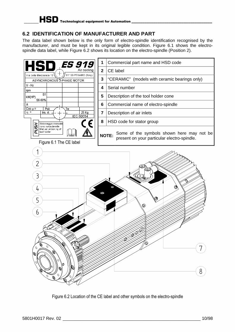
6.2 IDENTIFICATION OF MANUFACTURER AND PARTThe data label shown below is the only form of electro-spindle identification recognised by themanufacturer, and must be kept in its original legible condition. Figure 6.1 shows the electro-spindle data label, while Figure 6.2 shows its location on the electro-spindle (Position 2).
1 Commercial part name and HSD code
2 CE label
3 “CERAMIC” (models with ceramic bearings only)
4 Serial number
5 Description of the tool holder cone
6 Commercial name of electro-spindle
7 Description of air inlets
8 HSD code for stator group
Figure 6.1 The CE labelNOTE: Some of the symbols shown here may not be
present on your particular electro-spindle.
654
3
7
8
21
Figure 6.2 Location of the CE label and other symbols on the electro-spindle

______HSD Technological equipment for Automation _____________________________________
5801H0017 Rev. 02 _________________________________________________________ 11/98
6.3 DESCRIPTION OF THE MAIN PARTS OF THE ELECTRO-SPINDLE
1
2
3
4
5
6
7
8
10
11
12
13
9
Figure 6.3 General view of the electro-spindle
1 Cooling fan2 Sensor compartment3 Manual tool holder release button4 Configurable terminal block (optional)5 C axis sensor connector (optional C axis)6 Spindle nose7 Spindle shaft8 Compressed air connectors9 Electrical terminals
10 Exhaust air silencer (one on each side)11 Threaded service holes (see section 9.3.4 )12 Temperature sensor for front bearings (optional)13 “T” slots for anchoring to support
______HSD Technological equipment for Automation _____________________________________
5801H0017 Rev. 02 _________________________________________________________ 12/98
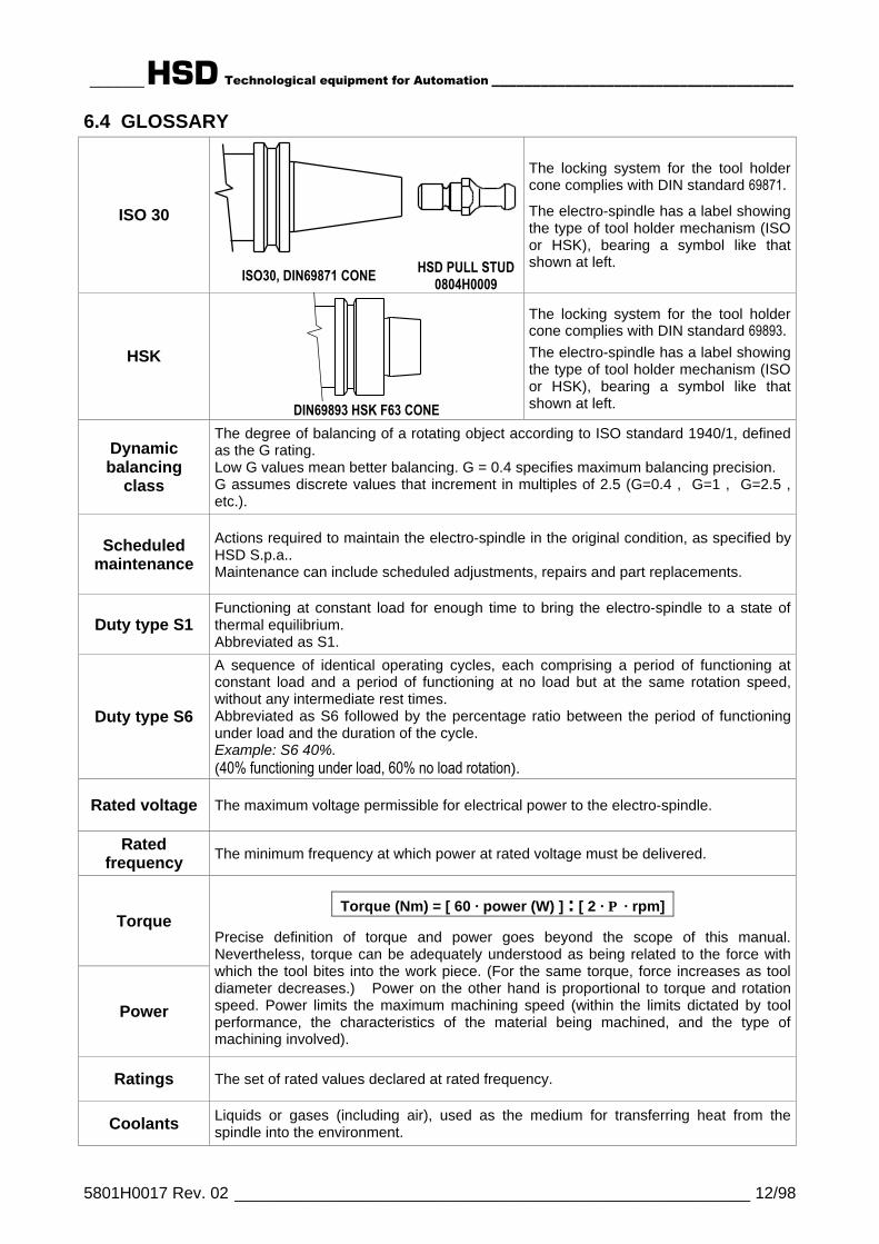
6.4 GLOSSARY
ISO 30
ISO30, DIN69871 CONE HSD PULL STUD0804H0009
The locking system for the tool holdercone complies with DIN standard 69871.
The electro-spindle has a label showingthe type of tool holder mechanism (ISOor HSK), bearing a symbol like thatshown at left.
HSK
DIN69893 HSK F63 CONE
The locking system for the tool holdercone complies with DIN standard 69893.The electro-spindle has a label showingthe type of tool holder mechanism (ISOor HSK), bearing a symbol like thatshown at left.
Dynamicbalancing
class
The degree of balancing of a rotating object according to ISO standard 1940/1, definedas the G rating.Low G values mean better balancing. G = 0.4 specifies maximum balancing precision.G assumes discrete values that increment in multiples of 2.5 (G=0.4 , G=1 , G=2.5 ,etc.).
Scheduledmaintenance
Actions required to maintain the electro-spindle in the original condition, as specified byHSD S.p.a..Maintenance can include scheduled adjustments, repairs and part replacements.
Duty type S1Functioning at constant load for enough time to bring the electro-spindle to a state ofthermal equilibrium.Abbreviated as S1.
Duty type S6
A sequence of identical operating cycles, each comprising a period of functioning atconstant load and a period of functioning at no load but at the same rotation speed,without any intermediate rest times.Abbreviated as S6 followed by the percentage ratio between the period of functioningunder load and the duration of the cycle.Example: S6 40%.(40% functioning under load, 60% no load rotation).
Rated voltage The maximum voltage permissible for electrical power to the electro-spindle.
Ratedfrequency The minimum frequency at which power at rated voltage must be delivered.
Torque
Power
..Torque (Nm) = [ 60 · power (W) ] : [ 2 · Π · rpm]..
Precise definition of torque and power goes beyond the scope of this manual.Nevertheless, torque can be adequately understood as being related to the force withwhich the tool bites into the work piece. (For the same torque, force increases as tooldiameter decreases.) Power on the other hand is proportional to torque and rotationspeed. Power limits the maximum machining speed (within the limits dictated by toolperformance, the characteristics of the material being machined, and the type ofmachining involved).
Ratings The set of rated values declared at rated frequency.
Coolants Liquids or gases (including air), used as the medium for transferring heat from thespindle into the environment.
______HSD Technological equipment for Automation _____________________________________
5801H0017 Rev. 02 _________________________________________________________ 13/98
§ 7 TECHNICAL SPECIFICATIONS
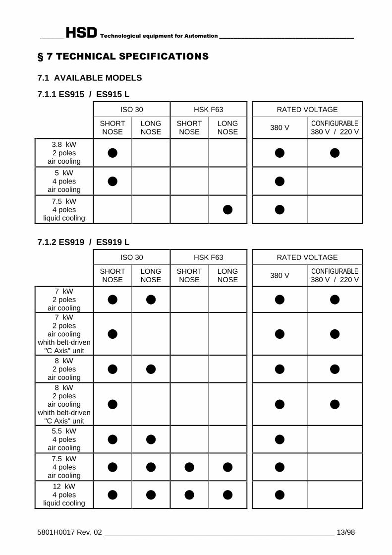
7.1 AVAILABLE MODELS
7.1.1 ES915 / ES915 L
ISO 30 HSK F63 RATED VOLTAGE
SHORTNOSE
LONGNOSE
SHORTNOSE
LONGNOSE 380 V CONFIGURABLE
380 V / 220 V
3.8 kW2 poles
air cooling¦ ¦ ¦
5 kW4 poles
air cooling¦ ¦
7.5 kW4 poles
liquid cooling¦ ¦
7.1.2 ES919 / ES919 L
ISO 30 HSK F63 RATED VOLTAGE
SHORTNOSE
LONGNOSE
SHORTNOSE
LONGNOSE 380 V CONFIGURABLE
380 V / 220 V
7 kW2 poles
air cooling¦ ¦ ¦ ¦
7 kW2 poles
air coolingwhith belt-driven
"C Axis" unit
¦ ¦ ¦
8 kW2 poles
air cooling¦ ¦ ¦ ¦
8 kW2 poles
air coolingwhith belt-driven
"C Axis" unit
¦ ¦ ¦
5.5 kW4 poles
air cooling¦ ¦ ¦
7.5 kW4 poles
air cooling¦ ¦ ¦ ¦ ¦
12 kW4 poles
liquid cooling¦ ¦ ¦ ¦ ¦

______HSD Technological equipment for Automation _____________________________________
5801H0017 Rev. 02 _________________________________________________________ 14/98
7.2 TECHNICAL SPECIFICATIONS OF ES915
7.2.1 Overall dimensions of ES915
______HSD Technological equipment for Automation _____________________________________
5801H0017 Rev. 02 _________________________________________________________ 15/98
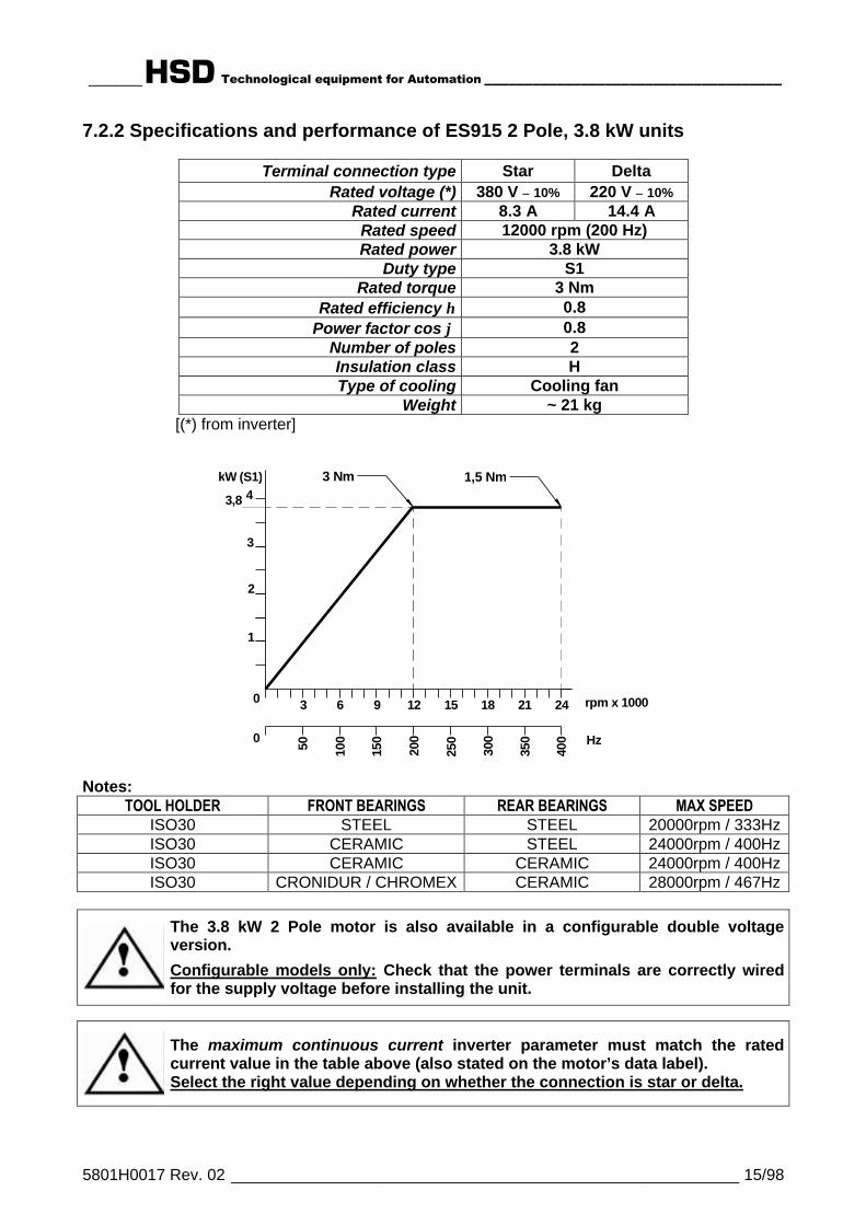
7.2.2 Specifications and performance of ES915 2 Pole, 3.8 kW units
Terminal connection type Star DeltaRated voltage (*) 380 V ± 10% 220 V ± 10%
Rated current 8.3 A 14.4 ARated speed 12000 rpm (200 Hz)Rated power 3.8 kW
Duty type S1Rated torque 3 Nm
Rated efficiency η 0.8Power factor cos ϕ 0.8
Number of poles 2Insulation class HType of cooling Cooling fan
Weight ~ 21 kg[(*) from inverter]
kW (S1)
Hz
0 3 6 9 12 15 18 21 24
1
2
3
4
0
50
100
150
200
250
300
350
400
3,8
3 Nm 1,5 Nm
rpm x 1000
Notes:TOOL HOLDER FRONT BEARINGS REAR BEARINGS MAX SPEED
ISO30 STEEL STEEL 20000rpm / 333HzISO30 CERAMIC STEEL 24000rpm / 400HzISO30 CERAMIC CERAMIC 24000rpm / 400HzISO30 CRONIDUR / CHROMEX CERAMIC 28000rpm / 467Hz
The 3.8 kW 2 Pole motor is also available in a configurable double voltageversion.
Configurable models only: Check that the power terminals are correctly wiredfor the supply voltage before installing the unit.
The maximum continuous current inverter parameter must match the ratedcurrent value in the table above (also stated on the motor’s data label).Select the right value depending on whether the connection is star or delta.

______HSD Technological equipment for Automation _____________________________________
5801H0017 Rev. 02 _________________________________________________________ 16/98
7.2.3 Specifications and performance of ES915 4 Pole, 5 kW units
Rated voltage (*) V 225 ±10% 380 ±10% 380 ±10% 380 ±10% 380 ±10% 380 ±10%Rated frequency Hz 233 400 500 667 800 933
Rated speed rpm 7000 12000 15000 20000 24000 28000Rated power kW 3 5 5 3.9 3 2,1
Duty type S1Rated torque Nm 4 4 3.2 1.7 1.2 0.7
Rated current A 12 12 10,5 9.2 7 4Rated efficiency η 0.8 0.8 0.8 0.8 0.8 0.8
Power factor cos ϕ 0.85 0.85 0.85 0.8 0.8 0.75Number of poles 4Insulation class FType of cooling Cooling fan
Weight kg ~ 21 [(*) from inverter]
kW (S1)
Hz
0 rpm x 1000 3 6 9 12 15 18 21 24 28
2,1
3,9
5
0
100 20
0
300
400
500
600
700
933
4
1
34 Nm
4 Nm 3,2 Nm
1,7 Nm
0,7 Nm
800
1,2 Nm
2
Notes:TOOL HOLDER FRONT BEARINGS REAR BEARINGS MAX SPEED
ISO30 STEEL STEEL 20000rpm / 667HzISO30 CERAMIC STEEL 24000rpm / 800HzISO30 CERAMIC CERAMIC 24000rpm / 800HzISO30 CRONIDUR / CHROMEX CERAMIC 28000rpm / 933Hz
i The 5 kW, 4 Pole motor is not available with configurable double voltage powerterminals.
The maximum continuous current inverter parameter must match the maximumvalue of the rated current in the table above (also stated on the motor’s datalabel).
______HSD Technological equipment for Automation _____________________________________
5801H0017 Rev. 02 _________________________________________________________ 17/98
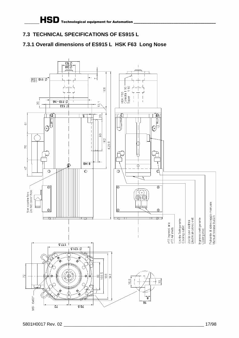
7.3 TECHNICAL SPECIFICATIONS OF ES915 L
7.3.1 Overall dimensions of ES915 L HSK F63 Long Nose

______HSD Technological equipment for Automation _____________________________________
5801H0017 Rev. 02 _________________________________________________________ 18/98
7.3.2 Specifications and performance of ES915 L 4 Pole, 7.5 kW units
Rated voltage (*) V 380 ±10% 380 ±10% 380 ±10% 380 ±10% 380 ±10% 380 ±10%Rated frequency Hz 400 500 600 667 733 933
Rated speed rpm 12000 15000 18000 20000 22000 28000
Duty type S1cont
S650%
S1cont
S650%
S1cont
S650%
S1cont
S650%
S1cont
S650%
S1cont
S650%
Rated power kW 6,5 7,5 6,5 7,5 6,1 6,7 5,8 6,4 5,5 6 3 3Rated torque Nm 5,2 6 4,1 4,8 3,2 3,6 2,8 3,1 2,4 2,6 1 1
Rated current A 15 18 15 18 14 15,7 13 16 13,1 14,1 7,5 7,5Rated efficiency η 0,82
Power factor cos ϕ 0,74Number of poles 4Insulation class FType of cooling Liquid cooling
Weight ofLONG NOSE variant kg ~ 29
[(*) from inverter]
kW (S6 50%)
Hz
0 rpm x 1000 3 6 9 12 15 18 21 24 28
1
2
3
4
5
66,7
0
100
200
300
400
500
600
700
933
7,56 Nm 4,8 Nm
3,6 Nm
800
2,6 Nm
1 Nm
6,43,1 Nm
Note:
TOOL HOLDER FRONT BEARINGS REAR BEARINGS MAX SPEEDHSK F63 STEEL STEEL 18000rpm / 600HzHSK F63 CERAMIC STEEL 20000rpm / 667HzHSK F63 CERAMIC CERAMIC 22000rpm / 733HzHSK F63 CRONIDUR / CHROMEX CERAMIC 28000rpm / 933Hz
i The 7.5 kW, 4 Pole motor is not available with configurable double voltagepower terminals.
The maximum continuous current inverter parameter must match the maximumvalue of the rated current in the table above (also stated on the motor’s datalabel).
______HSD Technological equipment for Automation _____________________________________
5801H0017 Rev. 02 _________________________________________________________ 19/98
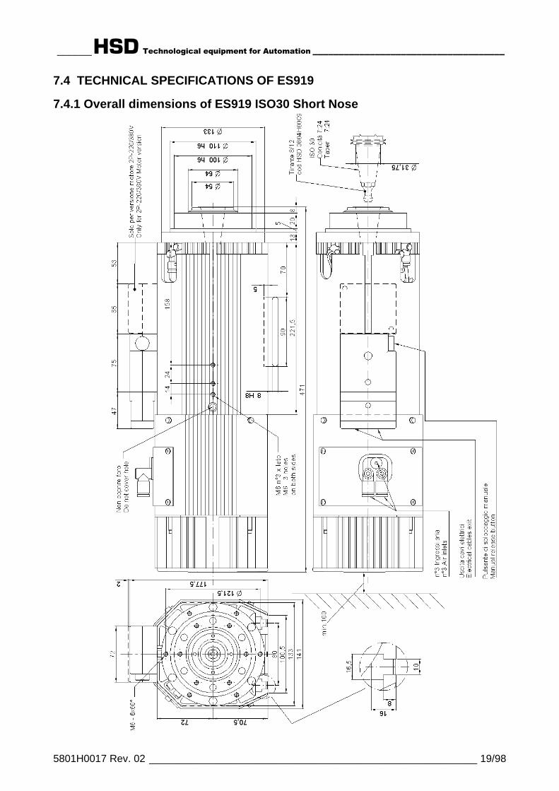
7.4 TECHNICAL SPECIFICATIONS OF ES919
7.4.1 Overall dimensions of ES919 ISO30 Short Nose

______HSD Technological equipment for Automation _____________________________________
5801H0017 Rev. 02 _________________________________________________________ 20/98
7.4.2 Overall dimensions of ES919 ISO30 Long Nose

______HSD Technological equipment for Automation _____________________________________
5801H0017 Rev. 02 _________________________________________________________ 21/98
7.4.3 Overall dimensions of ES919 HSK F63 Short Nose

______HSD Technological equipment for Automation _____________________________________
5801H0017 Rev. 02 _________________________________________________________ 22/98
7.4.4 Overall dimensions of ES919 HSK F63 Long Nose

______HSD Technological equipment for Automation _____________________________________
5801H0017 Rev. 02 _________________________________________________________ 23/98
7.4.5 Specifications and performance of ES919 2 Pole, 7 kW units
Terminal connection type Star DeltaRated voltage (*) 380 V ± 10% 220 V ± 10%
Rated current 16 A 28 ARated speed 12000 rpm (200 Hz)Rated power 7 kW
Duty type S1Rated torque 5.6 Nm
Rated efficiency η 0.8Power factor cos ϕ 0.8
Number of poles 2Insulation class HType of cooling Cooling fan
Weight of SHORT NOSE variant ~ 26 kgWeight of LONG NOSE variant ~ 31 kg
[(*) from inverter]
kW (S1)
Hz
0 rpm x 1000 3 6 9 12 15 18 21 24
1
2
3
4
5
6
7
0
50
100
150
200
250
300
350
400
5,6 Nm 3,3 Nm 2,8 Nm
Notes:TOOL HOLDER FRONT BEARINGS REAR BEARINGS MAX SPEED
ISO30 STEEL STEEL 20000rpm / 333HzISO30 CERAMIC STEEL 24000rpm / 400HzISO30 CERAMIC CERAMIC 24000rpm / 400HzISO30 CRONIDUR / CHROMEX CERAMIC 28000rpm / 467Hz
The 7 kW 2 Pole motor is also available in a configurable double voltageversion.
Configurable models only: Check that the power terminals are correctly wiredfor the supply voltage before installing the unit.
The maximum continuous current inverter parameter must match the ratedcurrent value in the table above (also stated on the motor’s data label).Select the right value depending on whether the connection is star or delta.

______HSD Technological equipment for Automation _____________________________________
5801H0017 Rev. 02 _________________________________________________________ 24/98
7.4.6 Specifications and performance of ES919 2 Pole, 8 kW units
Terminal connection type Star DeltaRated voltage (*) 380 V ± 10% 220 V ± 10%
Rated current 18 A 32 ARated speed 12000 rpm (200 Hz)Rated power 8 kW
Duty type S1Rated torque 6.4 Nm
Rated efficiency η 0.8Power factor cos ϕ 0.8
Number of poles 2Insulation class HType of cooling Cooling fan
Weight of SHORT NOSE variant ~ 26 kgWeight of LONG NOSE variant ~ 31 kg
[(*) from inverter]
kW (S1)
Hz
0 rpm x 1000 3 6 9 12 15 18 21 24
1
2
3
4
5
6
7
8
0
50
100
150
200
250
300
350
400
6,4 Nm 3,6 Nm 3,2 Nm
Notes:TOOL HOLDER FRONT BEARINGS REAR BEARINGS MAX SPEED
ISO30 STEEL STEEL 20000rpm / 333HzISO30 CERAMIC STEEL 24000rpm / 400HzISO30 CERAMIC CERAMIC 24000rpm / 400HzISO30 CRONIDUR / CHROMEX CERAMIC 28000rpm / 467Hz
The 8 kW 2 Pole motor is also available in a configurable double voltageversion.
Configurable models only: Check that the power terminals are correctly wiredfor the supply voltage before installing the unit.
The maximum continuous current inverter parameter must match the ratedcurrent value in the table above (also stated on the motor’s data label).Select the right value depending on whether the connection is star or delta.
______HSD Technological equipment for Automation _____________________________________
5801H0017 Rev. 02 _________________________________________________________ 25/98
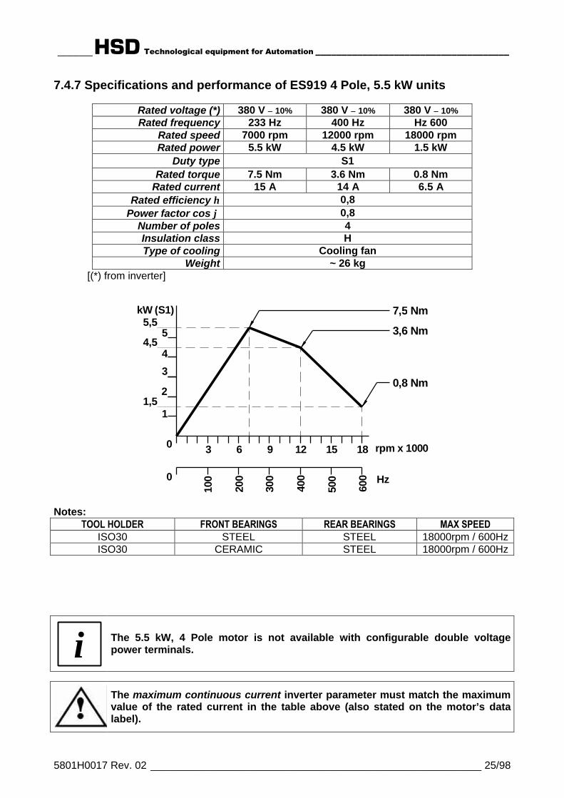
7.4.7 Specifications and performance of ES919 4 Pole, 5.5 kW units
Rated voltage (*) 380 V ± 10% 380 V ± 10% 380 V ± 10%Rated frequency 233 Hz 400 Hz Hz 600
Rated speed 7000 rpm 12000 rpm 18000 rpmRated power 5.5 kW 4.5 kW 1.5 kW
Duty type S1Rated torque 7.5 Nm 3.6 Nm 0.8 Nm
Rated current 15 A 14 A 6.5 ARated efficiency η 0,8
Power factor cos ϕ 0,8Number of poles 4Insulation class HType of cooling Cooling fan
Weight ~ 26 kg[(*) from inverter]
kW (S1)
Hz
0 rpm x 1000 3 6 9 12 15 18
1
2
3
4
5
0
100
200
300
400
500
600
5,5
4,5
1,5
7,5 Nm
3,6 Nm
0,8 Nm
Notes:TOOL HOLDER FRONT BEARINGS REAR BEARINGS MAX SPEED
ISO30 STEEL STEEL 18000rpm / 600HzISO30 CERAMIC STEEL 18000rpm / 600Hz
i The 5.5 kW, 4 Pole motor is not available with configurable double voltagepower terminals.
The maximum continuous current inverter parameter must match the maximumvalue of the rated current in the table above (also stated on the motor’s datalabel).

______HSD Technological equipment for Automation _____________________________________
5801H0017 Rev. 02 _________________________________________________________ 26/98
7.4.8 Specifications and performance of ES919 4 Pole, 7.5 kW units
Rated voltage (*) V 225 ± 10% 380 ± 10% 380 ± 10% 380 ± 10% 380 ± 10% 380 ± 10% 380 ± 10% 380 ± 10%Rated frequency Hz 233 400 500 667 733 800 867 933
Rated speed rpm 7000 12000 15000 20000 22000 24000 26000 28000Rated power kW 6 7.5 7.5 6 5.75 5.5 4.2 3.6
Duty type S1Rated torque Nm 8.2 6 4.8 2.9 2.5 2.2 1.5 1.2
Rated current A 25 20 17 15 13 13 10 11.5Rated efficiency η 0,8
Power factor cos ϕ 0,8Number of poles 4Insulation class FType of cooling Cooling fan
Weight of SHORT NOSE variant ~ 26 kgWeight of LONG NOSE variant ~ 31 kg
[(*) from inverter]
kW (S1)
Hz
0 rpm x 1000 3 6 9 12 15 18 21 24 28
1
2
3
4
5
6
7
0
100
200
300
400
500
600
700
933
4,2
7,58,2 Nm
6 Nm 4,8 Nm2,9 Nm
2,2 Nm
800
5,51,5 Nm
5,5
2,5 Nm
1,2 Nm
Notes:TOOL HOLDER FRONT BEARINGS REAR BEARINGS MAX SPEED
HSK F63 STEEL STEEL 18000rpm / 600HzHSK F63 CERAMIC STEEL 20000rpm / 667HzHSK F63 CERAMIC CERAMIC 22000rpm / 733HzHSK F63 CRONIDUR / CHROMEX CERAMIC 26000rpm / 867Hz
ISO30 STEEL STEEL 20000rpm / 667HzISO30 CERAMIC STEEL 24000rpm / 800HzISO30 CERAMIC CERAMIC 24000rpm / 800HzISO30 CRONIDUR / CHROMEX CERAMIC 28000rpm / 933Hz
i The 7.5 kW, 4 Pole motor is not available with configurable double voltagepower terminals.
The maximum continuous current inverter parameter must match the maximumvalue of the rated current in the table above (also stated on the motor’s datalabel).
______HSD Technological equipment for Automation _____________________________________
5801H0017 Rev. 02 _________________________________________________________ 27/98
7.5 TECHNICAL SPECIFICATIONS OF ES919 L
7.5.1 Overall dimensions of ES919 L ISO30 Short Nose
______HSD Technological equipment for Automation _____________________________________
5801H0017 Rev. 02 _________________________________________________________ 28/98
7.5.2 Overall dimensions of ES919 L ISO30 Long Nose

______HSD Technological equipment for Automation _____________________________________
5801H0017 Rev. 02 _________________________________________________________ 29/98
7.5.3 Overall dimensions of ES919 L HSK F63 Short Nose
______HSD Technological equipment for Automation _____________________________________
5801H0017 Rev. 02 _________________________________________________________ 30/98
7.5.4 Overall dimensions of ES919 L HSK F63 Long Nose
______HSD Technological equipment for Automation _____________________________________
5801H0017 Rev. 02 _________________________________________________________ 31/98
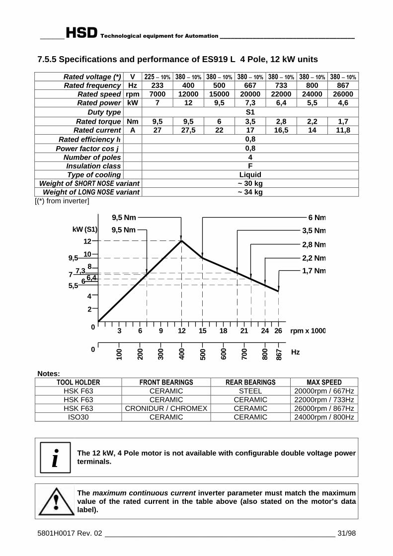
7.5.5 Specifications and performance of ES919 L 4 Pole, 12 kW units
Rated voltage (*) V 225 ± 10% 380 ± 10% 380 ± 10% 380 ± 10% 380 ± 10% 380 ± 10% 380 ± 10%Rated frequency Hz 233 400 500 667 733 800 867
Rated speed rpm 7000 12000 15000 20000 22000 24000 26000Rated power kW 7 12 9,5 7,3 6,4 5,5 4,6
Duty type S1Rated torque Nm 9,5 9,5 6 3,5 2,8 2,2 1,7
Rated current A 27 27,5 22 17 16,5 14 11,8Rated efficiency η 0,8
Power factor cos ϕ 0,8Number of poles 4Insulation class FType of cooling Liquid
Weight of SHORT NOSE variant ~ 30 kgWeight of LONG NOSE variant ~ 34 kg
[(*) from inverter]
kW (S1)
Hz
0 rpm x 1000 3 6 9 12 15 18 21 24 26
2
4
6
8
10
12
0
100
200
300
400
500
600
700
867
5,5
9,5 Nm
2,2 Nm
6 Nm
3,5 Nm
9,5 Nm
7 6,4
9,580
07,3 1,7 Nm
2,8 Nm
Notes:TOOL HOLDER FRONT BEARINGS REAR BEARINGS MAX SPEED
HSK F63 CERAMIC STEEL 20000rpm / 667HzHSK F63 CERAMIC CERAMIC 22000rpm / 733HzHSK F63 CRONIDUR / CHROMEX CERAMIC 26000rpm / 867Hz
ISO30 CERAMIC CERAMIC 24000rpm / 800Hz
i The 12 kW, 4 Pole motor is not available with configurable double voltage powerterminals.
The maximum continuous current inverter parameter must match the maximumvalue of the rated current in the table above (also stated on the motor’s datalabel).
______HSD Technological equipment for Automation _____________________________________
5801H0017 Rev. 02 _________________________________________________________ 32/98
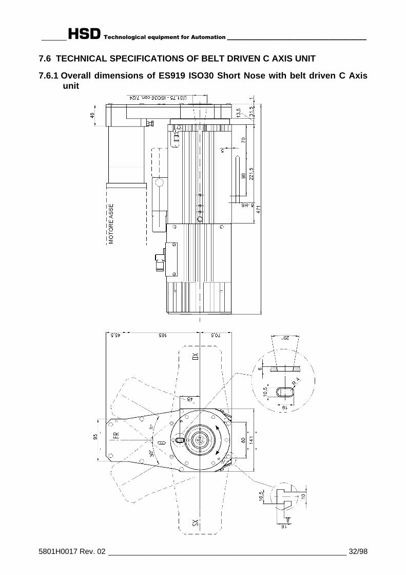
7.6 TECHNICAL SPECIFICATIONS OF BELT DRIVEN C AXIS UNIT
7.6.1 Overall dimensions of ES919 ISO30 Short Nose with belt driven C Axisunit
______HSD Technological equipment for Automation _____________________________________
5801H0017 Rev. 02 _________________________________________________________ 33/98
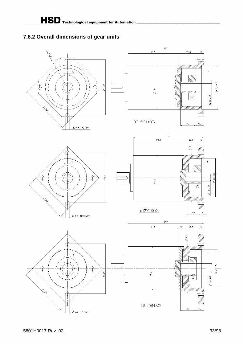
7.6.2 Overall dimensions of gear units
______HSD Technological equipment for Automation _____________________________________
5801H0017 Rev. 02 _________________________________________________________ 34/98
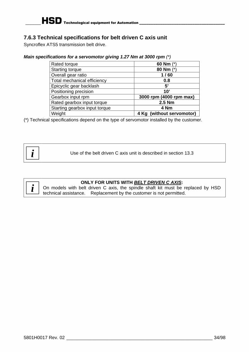
7.6.3 Technical specifications for belt driven C axis unitSyncroflex ATS5 transmission belt drive.
Main specifications for a servomotor giving 1.27 Nm at 3000 rpm (*)
Rated torque 60 Nm (*)Starting torque 80 Nm (*)Overall gear ratio 1 / 60Total mechanical efficiency 0.8Epicyclic gear backlash 5’Positioning precision 10’Gearbox input rpm 3000 rpm (4000 rpm max)Rated gearbox input torque 2.5 NmStarting gearbox input torque 4 NmWeight 4 Kg (without servomotor)
(*) Technical specifications depend on the type of servomotor installed by the customer.
i Use of the belt driven C axis unit is described in section 13.3
iONLY FOR UNITS WITH BELT DRIVEN C AXIS:
On models with belt driven C axis, the spindle shaft kit must be replaced by HSDtechnical assistance. Replacement by the customer is not permitted.
______HSD Technological equipment for Automation _____________________________________
5801H0017 Rev. 02 _________________________________________________________ 35/98
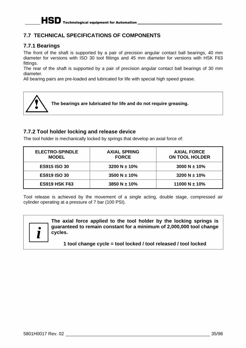
7.7 TECHNICAL SPECIFICATIONS OF COMPONENTS
7.7.1 BearingsThe front of the shaft is supported by a pair of precision angular contact ball bearings, 40 mmdiameter for versions with ISO 30 tool fittings and 45 mm diameter for versions with HSK F63fittings.The rear of the shaft is supported by a pair of precision angular contact ball bearings of 30 mmdiameter.All bearing pairs are pre-loaded and lubricated for life with special high speed grease.
The bearings are lubricated for life and do not require greasing.
7.7.2 Tool holder locking and release deviceThe tool holder is mechanically locked by springs that develop an axial force of:
ELECTRO-SPINDLEMODEL
AXIAL SPRINGFORCE
AXIAL FORCEON TOOL HOLDER
ES915 ISO 30--- 3200 N ± 10% _3000 N ± 10%
ES919 ISO 30--- 3500 N ± 10% _3200 N ± 10%
ES919 HSK F63 3850 N ± 10% 11000 N ± 10%
Tool release is achieved by the movement of a single acting, double stage, compressed aircylinder operating at a pressure of 7 bar (100 PSI).
iThe axial force applied to the tool holder by the locking springs isguaranteed to remain constant for a minimum of 2,000,000 tool changecycles.
1 tool change cycle = tool locked / tool released / tool locked
______HSD Technological equipment for Automation _____________________________________
5801H0017 Rev. 02 _________________________________________________________ 36/98
7.7.3 Automatic cleaning of the tool holder and internal pressurizationThe tool holder cone and its conical housing in the spindle shaft are automatically cleaned by theair purge during the tool change phase.
This prevents dirt from building up on the mating surface. The condition of the surface shouldnevertheless be regularly checked as described in section 12.1 on scheduled maintenance.
The pneumatic circuit for internal pressurization prevents dirt from entering the electro-spindle.This system is fed at 4 bar (58 PSI). Waste air is exhausted through the forward facing labyrinthports in the spindle nose.
Compressed air at 4 bar (58 PSI) must always be delivered to the electro-spindle even when it is not operating.
7.7.4 Proximity sensors
Sensor type: PNP proximity; NO (Normally Open)
Voltage 10 - 30 V (DC)
Maximum load 200 mA
No-load consumption < 10 mA
Rated read distance 0.8 MM
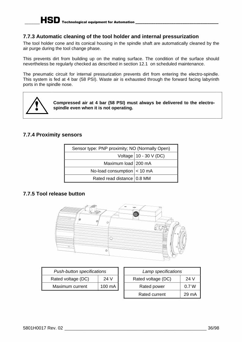
7.7.5 Tool release button
Push-button specifications Lamp specifications
Rated voltage (DC) 24 V Rated voltage (DC) 24 V
Maximum current 100 mA Rated power 0.7 W
Rated current 29 mA
______HSD Technological equipment for Automation _____________________________________
5801H0017 Rev. 02 _________________________________________________________ 37/98
7.7.6 Thermal switchThe electro-spindle motor windings are protected by a normally closed bi-metallic switch encasedin the stator. A second bi-metallic switch protects the cooling fan motor.The two switches are connected in series (see Figure 11.3).The switches open if temperature reaches a potentially damaging level and close again whentemperature drops to normal operating levels.This thermal switch system must be connected in series to the machine's safety stop system asshown in section 9.6.4 .The series of bi-metallic switches has the following specifications:
DC power 48 VDC MAX
AC power 230 VAC MAX
Current 1.6 A MAX
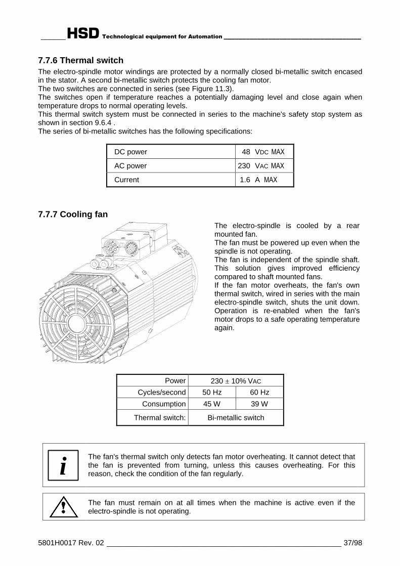
7.7.7 Cooling fanThe electro-spindle is cooled by a rearmounted fan.The fan must be powered up even when thespindle is not operating.The fan is independent of the spindle shaft.This solution gives improved efficiencycompared to shaft mounted fans.If the fan motor overheats, the fan's ownthermal switch, wired in series with the mainelectro-spindle switch, shuts the unit down.Operation is re-enabled when the fan'smotor drops to a safe operating temperatureagain.
Power 230 ± 10% VAC
Cycles/second 50 Hz 60 Hz
Consumption 45 W 39 W
Thermal switch: Bi-metallic switch
i The fan's thermal switch only detects fan motor overheating. It cannot detect thatthe fan is prevented from turning, unless this causes overheating. For thisreason, check the condition of the fan regularly.
The fan must remain on at all times when the machine is active even if theelectro-spindle is not operating.

______HSD Technological equipment for Automation _____________________________________
5801H0017 Rev. 02 _________________________________________________________ 38/98
§ 8 TRANSPORT AND MOVING
Lifting and moving electro-spindles can create situations of risk to persons nearby. Always followthe instructions provided by HSD and always use suitable lifting equipment.
Installation and assembly work must be performed only by specialist technicians.
Always use great care in lifting and moving electro-spindles and their components. Avoid impactsthat can damage the body which could cause malfunctions.
IT IS THE RESPONSIBILITY OF THE CUSTOMER TO ENSURE THAT THE LIFTING EQUIPMENT,CABLES, SLINGS AND CHAINS USED IS SUITABLE FOR THE PURPOSE IN TERMS OFFUNCTIONING AND LOAD CAPACITY.
8.1 STORAGEIf the electro-spindle is to be stored for any length of time, make sure that it is protected against theelements and in particular against damp, dust, and other forms of damage by the atmosphere orstorage environment.Check on the general condition of the electro-spindle periodically to prevent deterioration. Turn thespindle shaft by hand about once a month to keep the bearings free.
STORAGE TEMPERATURE: from –5°C (+23°F) to +55°C (+131°F)NON-CONDENSING RELATIVE HUMIDITY: from 5% to 90%
8.2 LIFTING THE ELECTRO-SPINDLE IN ITS CRATEThe electro-spindle is shipped in a wooden crate packed with expanded polystyrene foam. Theelectro-spindle itself is packed in a VCI plastic bag and is coated in protective grease to preventcorrosion. Use a clean cloth to wipe the protective grease off the new electro-spindle.(Note: The expanded polystyrene and the protective bag are plastics and must be disposed of assuch).
Figure 8.1 Example of how to lift the crate
______HSD Technological equipment for Automation _____________________________________
5801H0017 Rev. 02 _________________________________________________________ 39/98
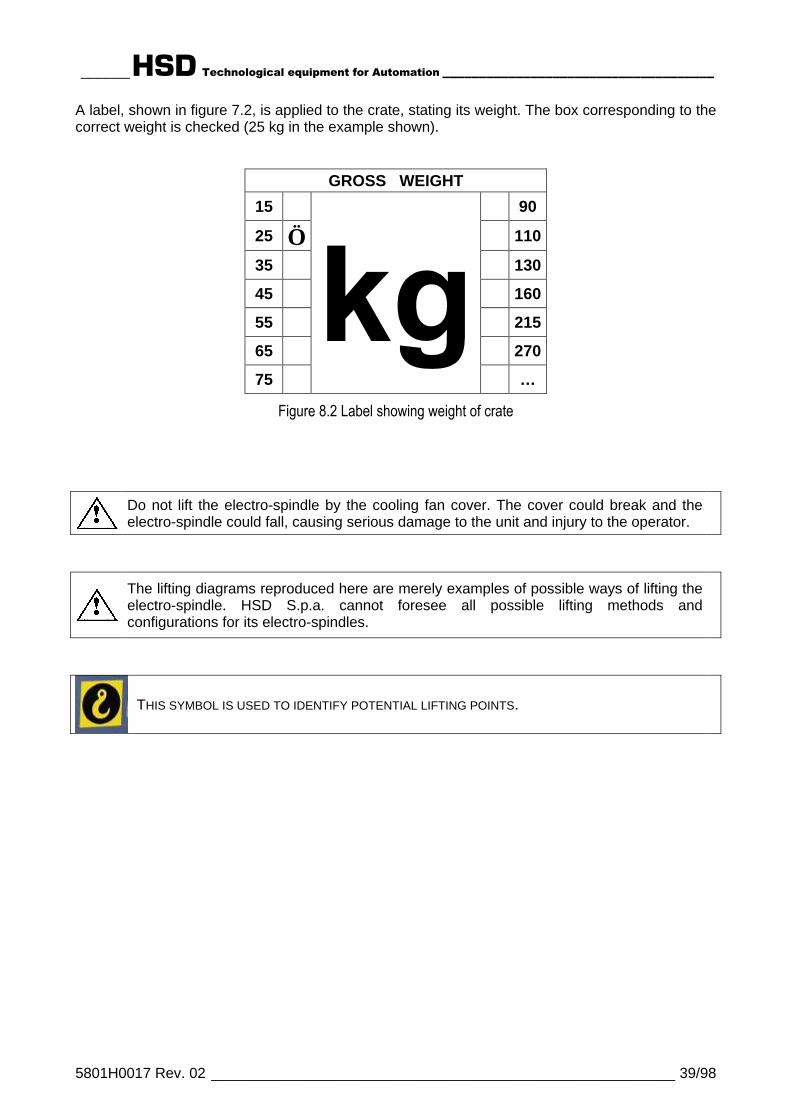
A label, shown in figure 7.2, is applied to the crate, stating its weight. The box corresponding to thecorrect weight is checked (25 kg in the example shown).
GROSS WEIGHT
15 90
25 √ 110
35 130
45 160
55 215
65 270
75 …
Figure 8.2 Label showing weight of crate
Do not lift the electro-spindle by the cooling fan cover. The cover could break and theelectro-spindle could fall, causing serious damage to the unit and injury to the operator.
The lifting diagrams reproduced here are merely examples of possible ways of lifting theelectro-spindle. HSD S.p.a. cannot foresee all possible lifting methods andconfigurations for its electro-spindles.
THIS SYMBOL IS USED TO IDENTIFY POTENTIAL LIFTING POINTS.

______HSD Technological equipment for Automation _____________________________________
5801H0017 Rev. 02 _________________________________________________________ 40/98
§ 9 INSTALLATION
9.1 FIRST CHECKBefore starting installation, check:
q That no part of the electro-spindle has been damaged during transport and/or handling.q That the connectors are not damaged in any way.
9.2 PREPARATION OF THE EQUIPMENT REQUIRED FOR INSTALLATION ONSITEAll work in preparation for installation of the electro-spindle is the responsibility of the customer(e.g. preparation of electrical power supplies, compressed air etc.).Make sure that the electrical power line to the electro-spindle is of adequate gauge and power.Connection of the unit to the power supply must only be done by qualified electricians. Thecustomer is responsible for all parts of the electrical power supply to the electro-spindle.The customer is expressly reminded that the electro-spindle must be correctly connected to earth.Furthermore, the earth connection must comply with applicable regulations in the country in whichthe unit is installed and must be duly checked and tested by a qualified electrician.See below for the installation layout and connection diagrams.
9.3 MECHANICAL INSTALLATION
9.3.1 The supporting surface
iThe supporting surface on which theelectro-spindle is fixed must have aflatness better than 0.02 mm. 0,02
9.3.2 Positioning the electro-spindle
100
Figure 9.1 Minimum clearance of fan
The electro-spindle must beinstalled with at least 100 mmof free space behind thecooling fan cover to ensure anadequate flow of cooling air.

______HSD Technological equipment for Automation _____________________________________
5801H0017 Rev. 02 _________________________________________________________ 41/98
9.3.3 Mechanical fixing of the electro-spindle
80100,510
816
16,5
Figure 9.2 T slots for anchoring the electro-spindle
Fix the electro-spindle to the carriage or spindle mounting using M8 bolts and nuts fitted in the Tslots and tightened to a torque of 20 Nm. Maximum permitted protrusion of the fixing bolts is 15mm, as shown in Figure 9.3. Greater protrusion can deform the electro-spindle body and lead toincorrect fixing, reduced machining precision and reduced machining safety.
(16)
15 M
AX1
MIN
Figure 9.3 Maximum permitted protrusion of bolts in T slots
Maximum protrusion of bolt: 15 mm.
Leave a clearance of at least 1 mm.
Excessive protrusion can deform theelectro-spindle body and reduce machiningprecision and safety.

______HSD Technological equipment for Automation _____________________________________
5801H0017 Rev. 02 _________________________________________________________ 42/98
9.3.4 Threaded service holesThere are a number of M6 threaded holes in the electro-spindle body, located as shown in Figure9.4.
Attention: never to block the silenced exhaust air holes(Position 4 in Figure 9.4).
43
1 2
1 Frontal service holes 6
2 C axis fixing holes 6
3 Side service holes 3 (ES919) per side2 (ES915) per side
4 Silenced exhaust air hole 1 per side
Figure 9.4 Service holes and silenced exhaust air hole

______HSD Technological equipment for Automation _____________________________________
5801H0017 Rev. 02 _________________________________________________________ 43/98
9.4 COMPRESSED AIR CONNECTIONS
9.4.1 Compressed air unionsThe compressed air unions are quick-fit unions. They are located as shown in Figure 9.5 and aredescribed in the table below.
2 1Figure 9.5 Location of the compressed air quick-fit unions
DESCRIPTION PRESSURE( bar / PSI )
EXTERNALHOSE Ø (mm)
1 Inlet for pressurization and conecleaning air 4 / 58 8
2 Tool release air inlet - outlet 7 / 100 8
______HSD Technological equipment for Automation _____________________________________
5801H0017 Rev. 02 _________________________________________________________ 44/98
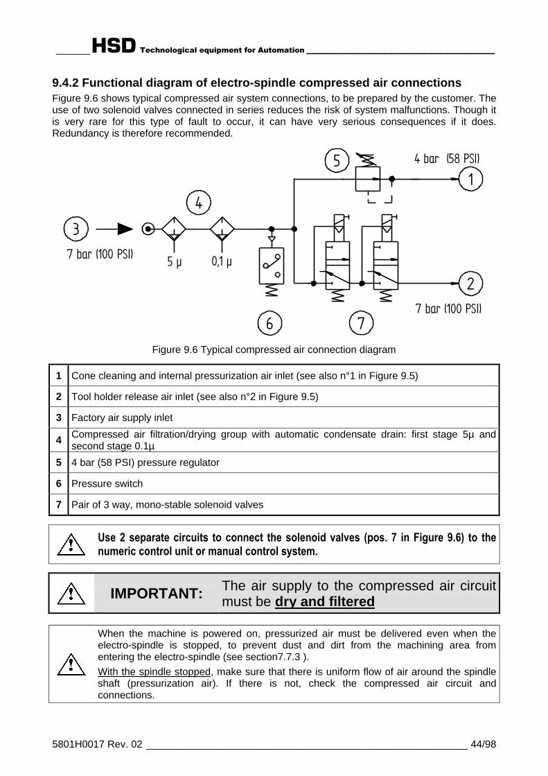
9.4.2 Functional diagram of electro-spindle compressed air connectionsFigure 9.6 shows typical compressed air system connections, to be prepared by the customer. Theuse of two solenoid valves connected in series reduces the risk of system malfunctions. Though itis very rare for this type of fault to occur, it can have very serious consequences if it does.Redundancy is therefore recommended.
5 µ 0,1 µ
1
2
3
5
6 7
4 bar (58 PSI)
4
7 bar (100 PSI)
7 bar (100 PSI)
Figure 9.6 Typical compressed air connection diagram
1 Cone cleaning and internal pressurization air inlet (see also n°1 in Figure 9.5)
2 Tool holder release air inlet (see also n°2 in Figure 9.5)
3 Factory air supply inlet
4 Compressed air filtration/drying group with automatic condensate drain: first stage 5µ andsecond stage 0.1µ
5 4 bar (58 PSI) pressure regulator
6 Pressure switch
7 Pair of 3 way, mono-stable solenoid valves
Use 2 separate circuits to connect the solenoid valves (pos. 7 in Figure 9.6) to thenumeric control unit or manual control system.
IMPORTANT: The air supply to the compressed air circuitmust be dry and filtered
When the machine is powered on, pressurized air must be delivered even when theelectro-spindle is stopped, to prevent dust and dirt from the machining area fromentering the electro-spindle (see section7.7.3 ).With the spindle stopped, make sure that there is uniform flow of air around the spindleshaft (pressurization air). If there is not, check the compressed air circuit andconnections.

______HSD Technological equipment for Automation _____________________________________
5801H0017 Rev. 02 _________________________________________________________ 45/98
9.5 COOLING CIRCUITLiquid-cooled models must be connected to a coolant circuit to dissipate the heat generated duringmachining. Coolant must be: water with 10% ethylene glycol.
Out
In
CONNECTION DESCRIPTION THREAD
Out Coolant circuit outlet G 1/4”
In Coolant circuit inlet G 1/4”
Hose internal diameter (at least) 8 mm ( 5/16 in. - 315 mils )
9.5.1 Cooler specifications
Cooling capacity 1600 W
Minimum delivery 3 litres/minute ( 0.11 cfm )
Coolant type H2O + 10% ethylene glycol
Cooler set temperature +25°C ( +77°F )
______HSD Technological equipment for Automation _____________________________________
5801H0017 Rev. 02 _________________________________________________________ 46/98
9.6 ELECTRICAL CONNECTIONS
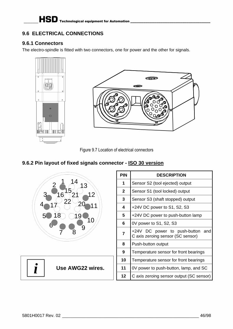
9.6.1 ConnectorsThe electro-spindle is fitted with two connectors, one for power and the other for signals.
Figure 9.7 Location of electrical connectors
9.6.2 Pin layout of fixed signals connector - ISO 30 version
PIN DESCRIPTION
1 Sensor S2 (tool ejected) output
2 Sensor S1 (tool locked) output
3 Sensor S3 (shaft stopped) output
4 +24V DC power to S1, S2, S3
5 +24V DC power to push-button lamp
6 0V power to S1, S2, S3
7 +24V DC power to push-button andC axis zeroing sensor (SC sensor)
8 Push-button output
7
1412 1315
123 16
8
2122 204 17 11
185 1910
6 9
9 Temperature sensor for front bearings
10 Temperature sensor for front bearings
11 0V power to push-button, lamp, and SCi Use AWG22 wires.12 C axis zeroing sensor output (SC sensor)

______HSD Technological equipment for Automation _____________________________________
5801H0017 Rev. 02 _________________________________________________________ 47/98
9.6.3 Pin layout of fixed signals connector - HSK F63 version
PIN DESCRIPTION
1 Sensor S2 (tool ejected) output
2 Sensor series S1 + S4 (tool locked)output
3 Sensor S3 (shaft stopped) output
4 +24V DC power to S1, S2, S3
5 +24V DC power to push-button lamp
6 0V power to S1, S2, S3, S4
7 +24V DC power to push-button and Caxis zeroing sensor (SC sensor)
8 Push-button output
7
1412 1315
123 16
8
2122 204 17 11
185 1910
6 9
9 Temperature sensor for front bearings
10 Temperature sensor for front bearings
11 0V power to push-button, lamp, and SC
12 C axis zeroing sensor output (SC sensor)i Use AWG22 wires.14 For maintenance
9.6.4 Pin layout of fixed power connector
PIN DESCRIPTION
1
Thermal switch: normally closed bi-metallic switch to be connected in seriesto machine safety stop system.
230V AC MAX; 48V DC MAX; 1.6A MAX
2 W PE common to pin 7
3 230V AC 50/60 Hz cooling fan
4 U Motor phase
5 Thermal switch (see pin 1)
2
5
3
4 6
18
97
6 V Motor phase
7 W PE common to pin 2
8 W Motor phaseiUse AWG10 wires for theeven pins and AWG18 forodd pins. 9 230V AC 50/60 Hz cooling fan

______HSD Technological equipment for Automation _____________________________________
5801H0017 Rev. 02 _________________________________________________________ 48/98
9.6.5 Tool holder release system electrical wiring diagram for electro-spindlesnot controlled by CNC
• The control system must disable the tool release push-buttonsignal while the spindle is rotating.
• The push-button must only be enabled when the spindle iscompletely stationary.
• Only use the push-button to lock/release tools on manuallycontrolled machines.
7 - 8 Pins 7 and 8 of the signalsconnector
BTool release button(See section 7.7.5 for technicalspecifications.)
PPressure switch to prevent toolrelease in case of insufficient airpressure
C Safety check (spindle stoppedcheck device)
ETool release solenoid valves (Seepos. 7 in Figure 9.6 and thewarnings for it.)
• When button “B” on the electro-spindle is pressed, the coils ofsolenoids “E” (not supplied) areenergized and the tool holder isreleased.
• Press button “B” to release the toolholder.
24V
7
B
8
P
C
0 V
E

______HSD Technological equipment for Automation _____________________________________
5801H0017 Rev. 02 _________________________________________________________ 49/98
9.6.6 Configurable power terminals (optional)
On request, some models canbe provided with powerterminals that can beconfigured either for delta orstar connections, for use withrated voltages of 380 V or 220V.
See section § 7 for details ofmodels available withconfigurable power terminals.
The figure on the left shows thelocation of the power terminals,under a protective cover fixed inplace by two screws.
Check what type of connections have been madein the terminal block before installing the unit.
CONNECTION DIAGRAM
STAR CONNECTIONS(rated voltage 380V)
DELTA CONNECTIONS(rated voltage 220V)
RED (STATOR)
380V - PIN6 BLACK (STATOR)
WHITE (STATOR)
BLACK (STATOR)
WHITE (STATOR)
RED (STATOR)380V - PIN4
380V - PIN8
BLACK (STATOR)
WHITE (STATOR)
RED (STATOR)RED (STATOR)
220V - PIN6
BLACK (STATOR)
WHITE (STATOR)
220V - PIN8
220V - PIN4
IMPORTANT:In star connections (for rated voltages of 380V)the terminals to be short circuited together arethose connected to a single wire.

______HSD Technological equipment for Automation _____________________________________
5801H0017 Rev. 02 _________________________________________________________ 50/98
§ 10 GENERAL CHECKS AFTER INSTALLATION AND DURINGSTART-UP
10.1 CHECKING THE ELECTRO-SPINDLE BEFORE START-UP
Positioning• There must be at least 100 mm of free space behind the cooling fan cover.
Compressed air connections• The internal pressurization and cone cleaning air hose must have an external
diameter of 8 mm, and must deliver dry, filtered air at a pressure of 4 bar (58 psi).• The tool change air hose must have an external diameter of 8 mm, and must
deliver dry, filtered air at a pressure of 7 bar (100 psi).• (For connection details see the labels on the unit itself and see also section 9.4
above).
i THE TOOL RELEASE CYLINDER ISSINGLE ACTING.
Electrical connections• The ground wire of the electro-spindle and
cooling fan must be connected to the ground(pins 2 and 7 of the power connector in thefigure on the right).
• The motor's thermal switch (NC switch) mustbe connected in series with the machine'ssafety stop system (pins 1 and 5 of the powerconnector in the figure on the right and section9.6.4 above).
• 2 pole 220V - 380V configurable motors only:The connections in the terminal block (380 Vstar or 220 V delta) must match the electro-spindle power. (See section 9.6.6 and § 7.)
2
5
3
4 6
18
9 7
Inverter programming• The maximum power voltage setting must match the value on the electro-spindle's
data label.• The minimum frequency value at which maximum voltage is delivered (rated
frequency, also referred to as knee or bend frequency) must match the value onthe electro-spindle's data label.
• The maximum frequency value must match the value on the electro-spindle's datalabel.
• The maximum continuous current value must match the value on the electro-spindle's data label.
• Contact HSD S.p.a. if you wish to check other inverter parameters.

______HSD Technological equipment for Automation _____________________________________
5801H0017 Rev. 02 _________________________________________________________ 51/98
10.2 CHECKING THE ELECTRO-SPINDLE ON FIRST START-UP• Warm up the electro-spindle briefly at no load (see section 11.3 ).• Make sure that pressurization air comes out from the labyrinth ports in the spindle
nose. (Check with the electro-spindle stationary.)PRESSURIZED AIR MUST ALWAYS BE PRESENT, EVEN WHEN THEELECTRO-SPINDLE IS NOT OPERATING.
• Check that the air from the fan flows towards the spindle nose.THE FAN MUST ALWAYS BE ON, EVEN WHEN THE ELECTRO-SPINDLE ISNOT OPERATING.
• Check that the air purge is on during tool changes.• Check that the compressed air hoses and unions do not interfere with cables or
machine parts during tool change movements (approx. 1 mm).• Check that the electro-spindle control sensors operate according to the logic
described in section 0.HSK F63 VERSIONS ONLY: THE ELECTRO-SPINDLE MUST ONLY BESTARTED UP WITH THE TOOL HOLDER LOCKED IN PLACE ([SENSOR 1 +SENSOR 4] ON AND SENSOR 2 OFF).
• The tool holder must be ejected about 0.5 – 0.9 mm in ISO 30 versions and 0.5 –0.6 mm in HSK F63 versions.TOOL CHANGES MUST ONLY TAKE PLACE WHEN THE SPINDLE AND THEMACHINE ARE STATIONARY (SENSOR 2 ON AND SENSOR 1(ISO30) ORSENSOR 1+4(HSK) OFF).
• The push-button on the terminal block must execute a manual tool change.THIS BUTTON MUST ONLY BE ENABLED WHEN THE SPINDLE ANDMACHINE ARE STATIONARY. (See section 9.6.5 .)
• The direction of spindle rotation must match the settings in the numeric controller.

______HSD Technological equipment for Automation _____________________________________
5801H0017 Rev. 02 _________________________________________________________ 52/98
§ 11 OPERATING THE ELECTRO-SPINDLE
11.1 CLIMATIC CONDITIONSHSD S.p.a. has designed and tested its electro-spindles to operate under the following standardclimatic conditions:
• Altitude not above 1000 m above sea level• Maximum ambient air temperature not above +40°C (+104°F)• Minimum ambient air temperature not below -15°C ( +5°F)• Coolant temperature (if relevant) at inlet to electro-spindle not above +27°C (+81°F)
and not below +23°C (+73°F).
Outside these tolerances some of the values declared in the tables and figures in section § 7 mayvary.Contact HSD S.p.a. for information on installations other than the standard ones illustrated ordescribed in this manual.
11.2 RUNNING INThe electro-spindle is run in in the factory prior to shipment. This ensures correct distribution of thelong-life grease in the bearing races. The run in cycle also includes comprehensive testing of allelectro-spindle controls and signal devices, and simulates various types of working cycles.
11.3 WARMING UPEvery day, when the electro-spindle is started up for the first time, let it warm up slowly withoutload, this ensures that the bearings reach their running temperature gradually, and that thebearing races expand evenly.The following warming up cycle is recommended, to be performed with the tool holder in placebut without actually machining (no load):50% maximum rated speed for 2 minutes.75% maximum rated speed for 2 minutes.100% maximum rated speed for 1 minute.Warm the electro-spindle up before machining whenever the machine has been left idle longenough for it to cool down to ambient temperature.
HSK VERSION ONLY:NEVER START THE ELECTRO-SPINDLE WITHOUT THE TOOL HOLDERIN PLACE.Starting an HSK electro-spindle with no tool holder puts the balance andfunctioning of the collet at risk.Push the tool holder in until it touches the face.

______HSD Technological equipment for Automation _____________________________________
5801H0017 Rev. 02 _________________________________________________________ 53/98
11.4 SELECTING THE TOOL HOLDER AND TOOL
11.4.1 ISO 30 tool holders
Always respect the following conditions when selecting a tool holder:• Cone geometry must comply with DIN 69871 standard.• Use only ISO 30 tool holders of AT3 precision rating.• Do not use tool holders that have lumps, hollows, or other shapes that could affect dynamic
balancing.• Dynamic balancing must be better than G=2.5 (ISO 1940 standard) at the electro-spindle's
maximum rated speed.• Balancing must always be done with the tool assembled (pull stud, cone, elastic collet, ring nut,
tool).• Only use pull studs (also referred to as retention knobs) provided by HSD (code 0804H0009).
Proceed as follows to install the pull stud in the ISO 30 cone:• Thoroughly clean the mating surfaces of the pull stud and its seat.• Smear the threads of the pull stud with LOCTITE 270 (or similar thread locking compound).• Tighten the pull stud in place to a torque of 62 Nm.• Leave the cone rest for at least 12 hours, so that the thread locking compound grips (or follow
the instructions of the locking compound manufacturer, if you have used an alternative toLOCTITE 270).
Figure 11.1 ISO 30 CONEDIN 69871
HSD 0804H0009PULL STUD
WARNING: Incorrect installation or the use of non-original HSD pullstuds can lead to the tool holder cone being thrown from the electro-spindle.
Use only pull studs (or retention knobs) from HSD (code 0804H0009).
i "Pull studs" are also referred to as "retention knobs".

______HSD Technological equipment for Automation _____________________________________
5801H0017 Rev. 02 _________________________________________________________ 54/98
11.4.2 HSK F63 tool holders
Always respect the following conditions when selecting a tool holder:• Cone geometry must comply with DIN 69893 standard.• Do not use tool holders that have lumps, hollows, or other shapes that could affect dynamic
balancing.• Dynamic balancing must be better than G=2.5 (ISO 1940 standard) at the electro-spindle's
maximum rated speed.• Balancing must always be done with the tool assembled (cone, elastic collet, ring nut, tool).
Figure 11.2 HSK F63 CONEDIN 69893
Never use tool holders that do not comply with the above conditions.Failure to comply can lead to breakage and accidental release of thetool holder cone, with potentially serious consequences for theoperator.
HSK VERSION ONLY:NEVER START THE ELECTRO-SPINDLE WITHOUT THE TOOLHOLDER IN PLACE.Starting an HSK electro-spindle with no tool holder puts the balance andfunctioning of the collet at risk.Push the tool holder in until it touches the face.

______HSD Technological equipment for Automation _____________________________________
5801H0017 Rev. 02 _________________________________________________________ 55/98
11.4.3 General safety precautions for tool holders
THE RIGHT CHOICE OF TOOL HOLDER IS ESSENTIAL FOR SAFEMACHINING. CAREFULLY FOLLOW THE INSTRUCTIONS GIVEN INSECTIONS 11.4.1 (ISO 30) AND 11.4.2 (HSK F63).
KEEP THE CONICAL SURFACES OF THE TOOL HOLDER AND ITSHOUSING IN THE SPINDLE SHAFT PERFECTLY CLEAN TO ENSUREA SAFE GRIP (SEE SECTION 12.1 ).
DURING MACHINING, TAKE GREAT CARE TO AVOID CONTACTBETWEEN NON-CUTTING ROTATING PARTS AND THE WORK.
DIRT MUST NOT BE ALLOWED TO ENTER THE CONICAL HOUSING.CLOSE IT WITH A SUITABLE PLUG OR A SPARE TOOL HOLDER.
AT THE END OF THE WORKING DAY, ALWAYS REMOVE THE TOOLHOLDER FROM THE SPINDLE, TO PREVENT IT FROM STICKING.
PROTECT OR COVER THE SPINDLE NOSE AGAINSTCONTAMINATION.

______HSD Technological equipment for Automation _____________________________________
5801H0017 Rev. 02 _________________________________________________________ 56/98
11.4.4 Choosing tools
Dynamic balancing must be better than G=2.5 (ISO 1940 standard) at the electro-spindle'smaximum rated speed.
Always respect the following conditions when selecting a tool:
• Only use fully sharpened tools, and make sure that they are securely locked in the tool holder.• Never use bent or damaged tools, chipped tools, or tools that are not perfectly balanced.• Always make sure that the mating surfaces of a tool are perfectly clean and dent free before
fitting the tool in the collet and tool holder.• Never use tools at speeds in excess of the rated speed by the manufacturer.• Always ensure that the following essential requirements are met before using any tool at high
speed:- The tool must be of compact, short, and lightweight design.- The tool must be a precision instrument, and any inserts must be secured tightly.- The tool must be balanced and must mate symmetrically with the tool holder.- The cutting surfaces of the tool must be located near its centre of rotation.

______HSD Technological equipment for Automation _____________________________________
5801H0017 Rev. 02 _________________________________________________________ 57/98
11.5 SPEED LIMITATIONS
ALWAYS RESPECT THE MAXIMUM TOOL SPEED (RPM)SPECIFIED BY THE TOOL MANUFACTURER.
Never exceed the maximum speed specified by the tool manufacturer.It is the operator's responsibility to decide whether to perform certain machining operations atslower speeds (NEVER HIGHER) than those specified by the tool manufacturer or those listed asguidelines in the following pages.
11.5.1 Content of graphsThe graphs on the following pages show sample maximum no-load electro-spindle rotation speeds.These have been calculated for different total weights of the TOOL + TOOL HOLDER assembly(including ring nut and elastic collet), and for different distances between the nose of the electro-spindle and the centre of gravity “G” of the tool + tool holder assembly.The tool + tool holder assembly has been considered as a single mass applied at the centre ofgravity “G” (without considering size or shape).The degree of balancing is that recommended in the previous sections.
The graphs on the following pages are purely indicative. HSD S.p.a. does not know and thegraphs therefore cannot take into account details of individual machining operations, toolspecifications, or characteristics of the material being machined. It is therefore the operator'sresponsibility to determine maximum safe speed on a case by case basis.
11.5.2 Reading the graphs1. Find the graph for your own electro-spindle.2. Select the curve for distance “X” between the nose of the spindle and the centre of gravity “G”
of the tool + tool holder assembly. If the value of “X” measured on your electro-spindle does notappear in the graph, use the curve for the next higher value of “X” (see example).
3. Read off the maximum speed value for the weight of the tool + tool holder assembly.
EXAMPLEYou have an ES919 L HSK F63 SHORT NOSE electro-spindle, and want to use a tool + toolholder assembly weighing a total of 3.5 kg (including ring nut and elastic collet). The distancebetween the spindle nose and the centre of gravity “G” of the tool + tool holder assembly “X” is 120mm.
1. The graphic for this particular electro-spindle is that in section 11.5.6 .2. Since there is no curve for “X”=120 mm, use the curve for the next higher value, i.e. the yellow
curve for “X”=130 mm.3. Against the weight 3.5 kg read off the maximum no-load speed, which is 10000 rpm.
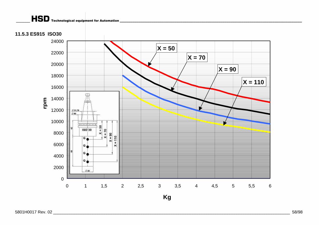
______ HSD Technological equipment for Automation _______________________________________________________________________________________
5801H0017 Rev. 02 ______________________________________________________________________________________________________ 58/98
11.5.3 ES915 ISO30
0 1 1,5 2 2,5 3 3,5 4 4,5 5 5,5 60
2000
4000
6000
8000
10000
12000
14000
16000
18000
20000
22000
24000
Kg
X = 50
X = 70
X = 90
X = 110
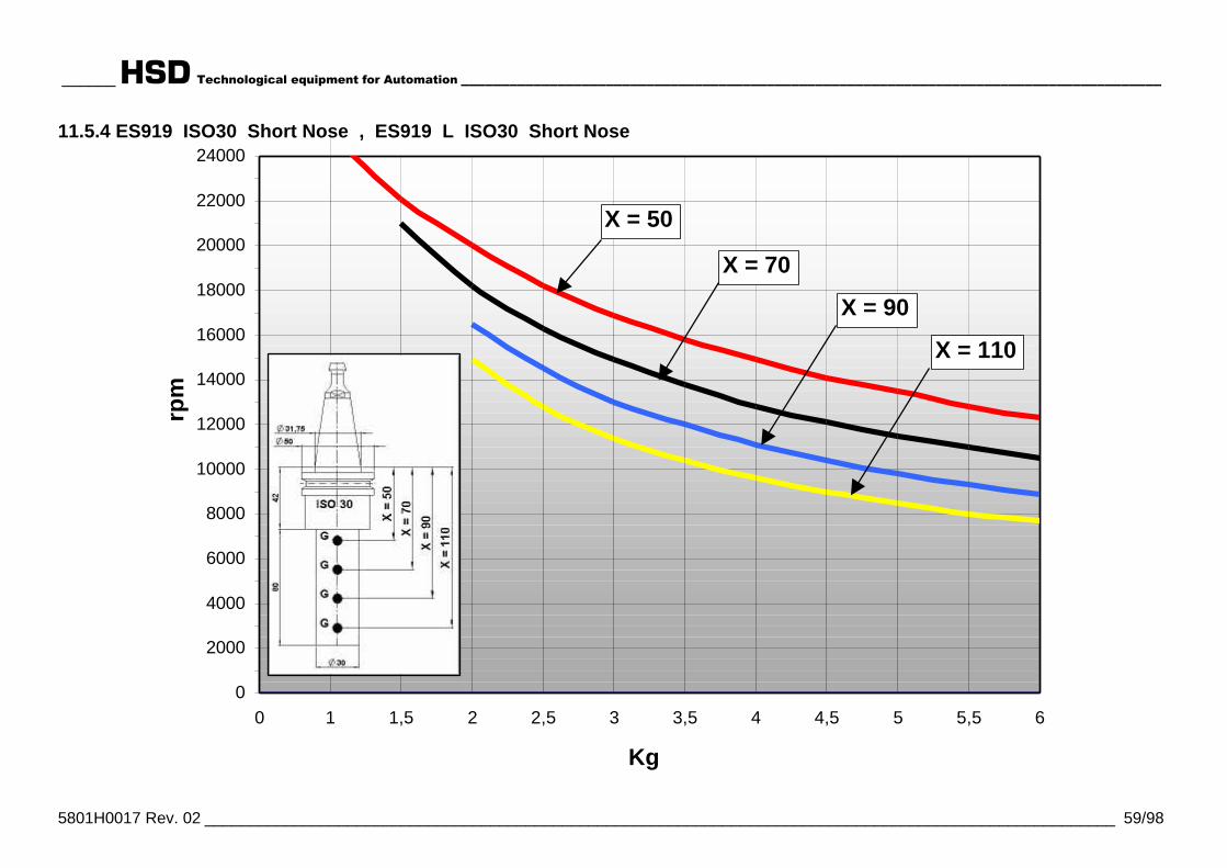
______ HSD Technological equipment for Automation _______________________________________________________________________________________
5801H0017 Rev. 02 ______________________________________________________________________________________________________ 59/98
11.5.4 ES919 ISO30 Short Nose , ES919 L ISO30 Short Nose
0 1 1,5 2 2,5 3 3,5 4 4,5 5 5,5 60
2000
4000
6000
8000
10000
12000
14000
16000
18000
20000
22000
24000
Kg
rpm
X = 50
X = 70
X = 90
X = 110
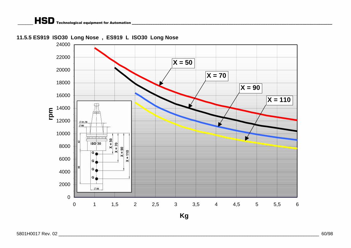
______ HSD Technological equipment for Automation _______________________________________________________________________________________
5801H0017 Rev. 02 ______________________________________________________________________________________________________ 60/98
11.5.5 ES919 ISO30 Long Nose , ES919 L ISO30 Long Nose
0 1 1,5 2 2,5 3 3,5 4 4,5 5 5,5 60
2000
4000
6000
8000
10000
12000
14000
16000
18000
20000
22000
24000
Kg
rpm
X = 50
X = 70
X = 90
X = 110
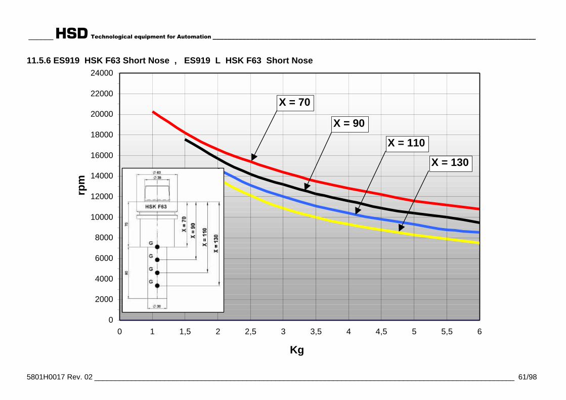
______ HSD Technological equipment for Automation _______________________________________________________________________________________
5801H0017 Rev. 02 ______________________________________________________________________________________________________ 61/98
11.5.6 ES919 HSK F63 Short Nose , ES919 L HSK F63 Short Nose
0 1 1,5 2 2,5 3 3,5 4 4,5 5 5,5 60
2000
4000
6000
8000
10000
12000
14000
16000
18000
20000
22000
24000
Kg
rpm
X = 70
X = 90
X = 110
X = 130
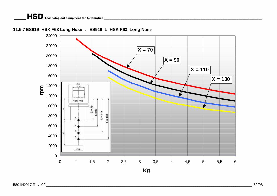
______ HSD Technological equipment for Automation _______________________________________________________________________________________
5801H0017 Rev. 02 ______________________________________________________________________________________________________ 62/98
11.5.7 ES919 HSK F63 Long Nose , ES919 L HSK F63 Long Nose
0 1 1,5 2 2,5 3 3,5 4 4,5 5 5,5 60
2000
4000
6000
8000
10000
12000
14000
16000
18000
20000
22000
24000
Kg
rpm
X = 70
X = 90
X = 110
X = 130

______HSD Technological equipment for Automation _____________________________________
5801H0017 Rev. 02 _________________________________________________________ 63/98
11.6 SENSOR FUNCTIONING
Note: The optional sensors (the “spindle shaft stopped” sensor S3and the “front bearing temperature sensor”) are optionallyinstalled in ISO 30 and HSK F63 versions. They are bothdescribed in detail in chapter § 13, where sensor “SC” for theoptional “C” axis is also described.This section only describes the sensors present in the basicconfiguration.
iThe technical specifications of the sensors described here aregiven in section 7.7.4 .
Sensor output is delivered to the “signals connector” describedin sections 9.6.2 (ISO 30) and 9.6.3 (HSK F63).
11.6.1 ISO 30 versionsISO 30 versions are fitted with two electro-spindle sensors. Sensors S1 and S2 perform thefunctions described below.
S1Detects correct locking of the tool holder. It is used toprovide the NC with a safety signal permitting spindlerotation.
CONDITION OUTPUT S1Tool holder locked +24 V
No tool holder 0 V
Tool holder ejected(collet open) 0 V
Always monitor S1 during electro-spindle rotation and stoprotation if S1 drops to 0 Volt.
i Ignore S1 from the moment the tool eject command isgiven until the next tool locking command is given.

______HSD Technological equipment for Automation _____________________________________
5801H0017 Rev. 02 _________________________________________________________ 64/98
S2Important during tool changes. Detects ejection of thetool holder, permitting the next phase in the tool changecycle to take place.
CONDITION OUTPUT S2Tool holder locked 0 V
No tool holder 0 V
Tool holder ejected(collet open) +24 V
11.6.2 HSK F63 versionsHSK F63 versions are fitted with three electro-spindle sensors: S1, S2 and S4. S1 and S4 areconnected in series and provide a single output. S1, S2 and S4 perform the functions describedbelow.
S1 + S4Wired in series to detect correct locking of the toolholder. Their output is used to provide the NC with asafety signal permitting spindle rotation.
CONDITION OUTPUT <S1+S4>Tool holder locked +24 V
No tool holder 0 V
Tool holder ejected(collet open) 0 V
Always monitor the output from <S1+S4> during electro-spindle rotation and stop rotation if it drops to 0 Volt.
i Ignore <S1+S4> from the moment the tool eject commandis given until the next tool locking command is given.

______HSD Technological equipment for Automation _____________________________________
5801H0017 Rev. 02 _________________________________________________________ 65/98
S2Important during tool changes. Detects ejection of thetool holder, permitting the next phase in the tool changecycle to take place.
CONDITION OUTPUT S2Tool holder locked 0 V
No tool holder 0 V
Tool holder ejected(collet open) +24 V
11.7 THERMAL SWITCHThe electro-spindle is protected by two normally closed bi-metallic switches wired in series. Theseprotect the electro-spindle motor and cooling fan motor respectively.They must be connected in series with the machine's safety stop system or inverter safety stopsystem (see section 9.6.4 ).The switches open if temperature reaches a potentially damaging level, tripping the machine'ssafety stop system and stopping machining. They close again when temperature drops to normaloperating levels.
C Power connector(see section 9.6.4 )
S Bi-metallic switches
M Electro-spindle motor
F Cooling fan
PE Electrical protection W
C
3 ~
PIN 1
PE
FM
S
PIN 8
PIN 9PIN 3
PIN 6PIN 4
PIN 7PIN 2
PIN 5S
Figure 11.3 Bi-metallic switch and motor wiring
i The fan's thermal switch only detects fan motor overheating. It cannot detect thatthe fan is prevented from turning, unless this causes overheating. For thisreason, check the condition of the fan regularly.
The fan must remain on at all times when the machine is active even if theelectro-spindle is not operating.

______HSD Technological equipment for Automation _____________________________________
5801H0017 Rev. 02 _________________________________________________________ 66/98
§ 12 MAINTENANCE
Read this section carefully before attempting any maintenance on the electro-spindle. This sectioncontains information that is important for the safety of maintenance personnel and for the reliabilityof maintenance work itself.
All applicable safety precautions must be taken whenever maintenance work is done on theelectro-spindle. In particular:
• Maintenance and/or lubrication must be performed only by qualified, expert personnel, with theauthorization of factory management, in compliance with applicable safety directives andstandards, and with the use of suitable tools and instruments.
• When performing maintenance, always wear suitable clothing such as tight fitting work overallsand safety shoes. Never wear long or slack clothing or clothes with parts that hang loose.
• When performing maintenance on a machine, mark it clearly with panels stating “MACHINEUNDERGOING MAINTENANCE”, and guard from unauthorized access.
During all maintenance work make sure that the electro-spindle is:• disconnected and insulated from the electrical power supply;• fully stopped (not still spinning).
Maintenance managers must ensure that their team is trained to ensure optimum co-ordination andsafety. All persons performing maintenance must remain fully visible to colleagues at all times sothat they can signal for assistance if necessary.
WARNING: USE ONLY SUITABLE LIFTING AND MOVING EQUIPMENT TO DISCONNECT ORREMOVE HEAVY PARTS FROM THE MACHINE.
i SPECIAL TOOLS ARE NOT NORMALLY REQUIRED FOR ELECTRO-SPINDLE MAINTENANCE.
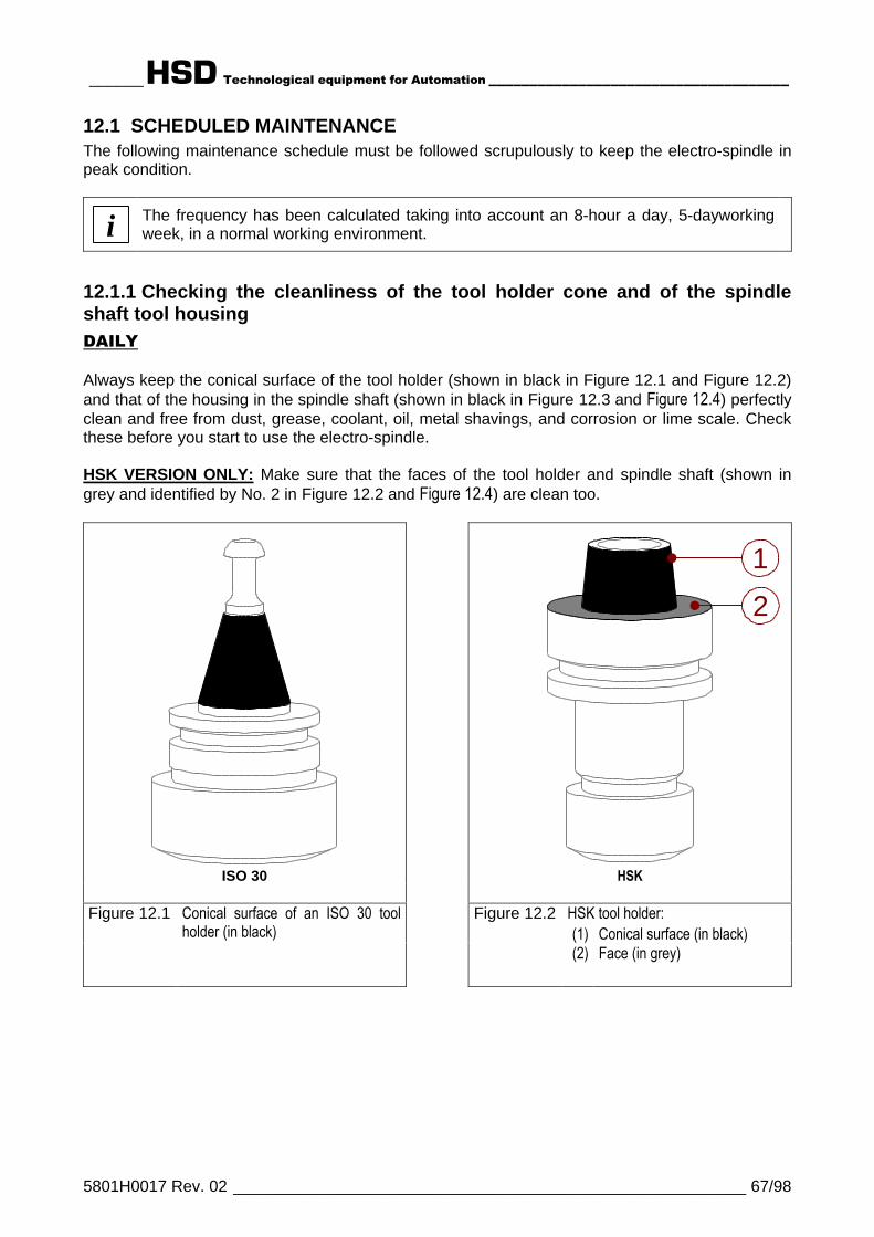
______HSD Technological equipment for Automation _____________________________________
5801H0017 Rev. 02 _________________________________________________________ 67/98
12.1 SCHEDULED MAINTENANCEThe following maintenance schedule must be followed scrupulously to keep the electro-spindle inpeak condition.
i The frequency has been calculated taking into account an 8-hour a day, 5-dayworkingweek, in a normal working environment.
12.1.1 Checking the cleanliness of the tool holder cone and of the spindleshaft tool housingDAILY
Always keep the conical surface of the tool holder (shown in black in Figure 12.1 and Figure 12.2)and that of the housing in the spindle shaft (shown in black in Figure 12.3 and Figure 12.4) perfectlyclean and free from dust, grease, coolant, oil, metal shavings, and corrosion or lime scale. Checkthese before you start to use the electro-spindle.
HSK VERSION ONLY: Make sure that the faces of the tool holder and spindle shaft (shown ingrey and identified by No. 2 in Figure 12.2 and Figure 12.4) are clean too.
ISO 30
2
1
HSK
HSK tool holder:(1) Conical surface (in black)
Figure 12.1 Conical surface of an ISO 30 toolholder (in black)
Figure 12.2
(2) Face (in grey)
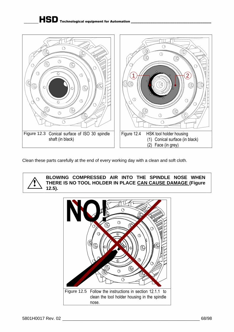
______HSD Technological equipment for Automation _____________________________________
5801H0017 Rev. 02 _________________________________________________________ 68/98
1 2
HSK tool holder housing(1) Conical surface (in black)
Figure 12.3 Conical surface of ISO 30 spindleshaft (in black)
Figure 12.4
(2) Face (in grey)
Clean these parts carefully at the end of every working day with a clean and soft cloth.
BLOWING COMPRESSED AIR INTO THE SPINDLE NOSE WHENTHERE IS NO TOOL HOLDER IN PLACE CAN CAUSE DAMAGE (Figure12.5).
NO!
Figure 12.5 Follow the instructions in section 12.1.1 toclean the tool holder housing in the spindlenose.

______HSD Technological equipment for Automation _____________________________________
5801H0017 Rev. 02 _________________________________________________________ 69/98
DIRTY MATING SURFACES CAUSE AN UNCORRECT TOOL HOLDERSEATING, WITH SERIOUS CONSEQUENCES FOR OPERATORSAFETY, ELECTRO-SPINDLE AND TOOL HOLDER WEAR, ANDMACHINING PRECISION.
USE A CLEAN AND SOFT CLOTH TO CLEAN THE CONICALSURFACES AND THE FACES SHOWN IN FIGURES FROM Figure 12.1TO Figure 12.4. ABSOLUTELY NEVER USE ABRASIVE TOOLS ORMATERIALS LIKE METAL BRUSHES, EMERY CLOTH, ACIDS ANDOTHER AGGRESSIVE CHEMICALS.
12.1.2 Cleaning the tool holder coneEVERY TWO WEEKS
Clean carefully the conical surface of the tool holder (shown in black in Figure 12.1 and Figure12.2) using a clean, soft cloth dipped in ethyl alcohol.
HSK VERSION ONLY: after cleaning by ethyl alcohol, spray the product KLÜBER LUSINPROTECT G 31, on the conical surface, and spread the product evenly using a clean, dry cloth.
12.1.3 Protecting the spindle shaft's conical housingDAILY
DIRT MUST NOT BE ALLOWED TO ENTER THE CONE SEAT. CLOSE ITWITH A SUITABLE PLUG OR A SPARE TOOL HOLDER.
AT THE END OF THE WORKING DAY, ALWAYS REMOVE THE TOOLHOLDER FROM THE SPINDLE, TO PREVENT IT FROM STICKING.
PROTECT OR COVER THE SPINDLE NOSE AGAINSTCONTAMINATION.
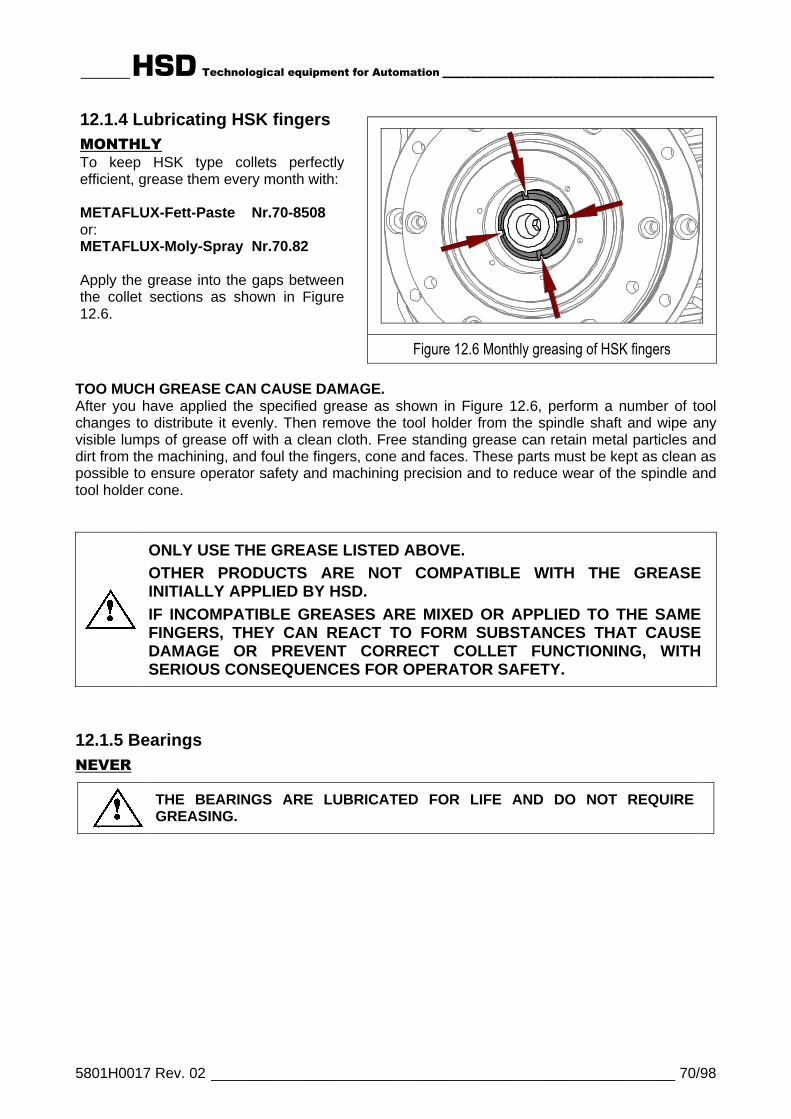
______HSD Technological equipment for Automation _____________________________________
5801H0017 Rev. 02 _________________________________________________________ 70/98
12.1.4 Lubricating HSK fingersMONTHLYTo keep HSK type collets perfectlyefficient, grease them every month with:
METAFLUX-Fett-Paste Nr.70-8508or:METAFLUX-Moly-Spray Nr.70.82
Apply the grease into the gaps betweenthe collet sections as shown in Figure12.6.
Figure 12.6 Monthly greasing of HSK fingers
TOO MUCH GREASE CAN CAUSE DAMAGE.After you have applied the specified grease as shown in Figure 12.6, perform a number of toolchanges to distribute it evenly. Then remove the tool holder from the spindle shaft and wipe anyvisible lumps of grease off with a clean cloth. Free standing grease can retain metal particles anddirt from the machining, and foul the fingers, cone and faces. These parts must be kept as clean aspossible to ensure operator safety and machining precision and to reduce wear of the spindle andtool holder cone.
ONLY USE THE GREASE LISTED ABOVE.OTHER PRODUCTS ARE NOT COMPATIBLE WITH THE GREASEINITIALLY APPLIED BY HSD.IF INCOMPATIBLE GREASES ARE MIXED OR APPLIED TO THE SAMEFINGERS, THEY CAN REACT TO FORM SUBSTANCES THAT CAUSEDAMAGE OR PREVENT CORRECT COLLET FUNCTIONING, WITHSERIOUS CONSEQUENCES FOR OPERATOR SAFETY.
12.1.5 BearingsNEVER
THE BEARINGS ARE LUBRICATED FOR LIFE AND DO NOT REQUIREGREASING.
______HSD Technological equipment for Automation _____________________________________
5801H0017 Rev. 02 _________________________________________________________ 71/98
12.2 REPLACING PARTSParts must only be removed and replaced by qualified and authorized personnel.
RESIDUAL RISKS:
THE DRAW BAR SPRING IS PRE-LOADED WITH A FORCEOF HUNDREDS OF KILOGRAMS. IN HSK MODELS INPARTICULAR THE DRAW BAR CAN BE VIOLENTLYEXPELLED FROM THE UNIT, WITH SERIOUS RISK OFINJURY, IF THE ELECTRO-SPINDLE IS DISASSEMBLED BYUNTRAINED PERSONNEL.
PERFORM ONLY THE TASKS DESCRIBED IN THISMANUAL. FOLLOW THE INSTRUCTIONS SCRUPULOUSLY.IN CASE OF DOUBT, CONTACT THE HSD TECHNICALASSISTANCE SERVICE.
ALL DISASSEMBLY AND RE-ASSEMBLY OPERATIONS MUST BE PERFORMEDWITH:
ABSOLUTE CERTAINTY THAT THE MACHINE IS STOPPED, THE CONTROLPANEL IS DISCONNECTED AT THE POWER SWITCH, AND THE SWITCHLOCKED, WITH THE KEYS HELD BY THE MAINTENANCE MANAGERABSOLUTE CERTAINTY THAT THE TOOL IN THE ELECTRO-SPINDLE ISSTATIONARYA WORKING ENVIRONMENT THAT IS EQUIPPED WITH ALL NECESSARY TOOLSAND EQUIPMENT AND FREE FROM SOURCES OF POTENTIAL DANGERTHOROUGH CLEANLINESS OF THE PARTS BEING FITTED, WHICH MUST ALSOBE EITHER DEGREASED OR LUBRICATED ACCORDING TO THEIR USE.
USE ONLY ORIGINAL HSD SPARE PARTS AND PERFORM ONLY THEINSTRUCTIONS DESCRIBED IN THIS MANUAL. NO OTHER WORK ON THEELECTRO-SPINDLE IS PERMITTED AND WOULD INVALIDATE THE WARRANTY.

______HSD Technological equipment for Automation _____________________________________
5801H0017 Rev. 02 _________________________________________________________ 72/98
12.2.1 Changing the spindle shaft kitTo replace the spindle shaft kit, follow the instructions given in the “Spindle Shaft Kit ReplacementManual” (code HSD 5802H0001) that comes with the kit and can be ordered from the TechnicalAssistance Service.
iONLY FOR UNITS WITH BELT DRIVEN C AXIS:
On models with belt driven C axis, the spindle shaft kit must be replaced by HSDtechnical assistance. Replacement by the customer is not permitted.
Figure 12.7 ES919 HSK F63 Short Nose spindle shaft kit
Figure 12.8 ES919 HSK F63 Long Nose spindle shaft kit
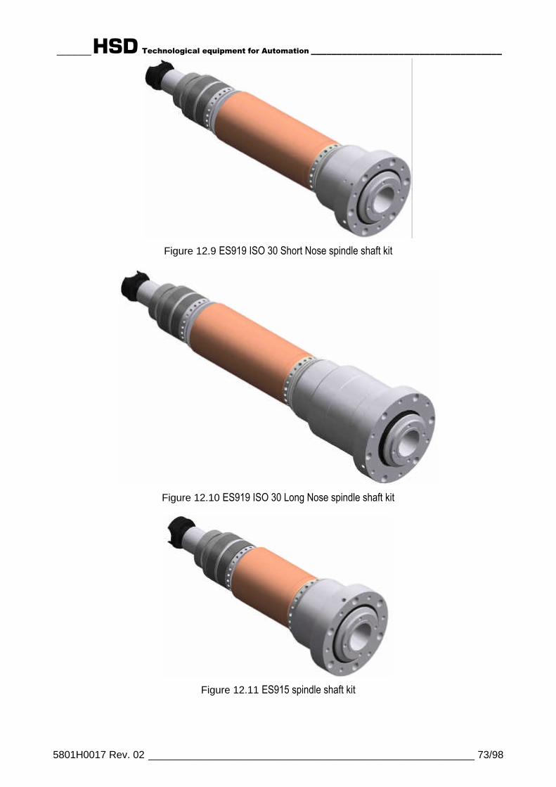
______HSD Technological equipment for Automation _____________________________________
5801H0017 Rev. 02 _________________________________________________________ 73/98
Figure 12.9 ES919 ISO 30 Short Nose spindle shaft kit
Figure 12.10 ES919 ISO 30 Long Nose spindle shaft kit
Figure 12.11 ES915 spindle shaft kit

______HSD Technological equipment for Automation _____________________________________
5801H0017 Rev. 02 _________________________________________________________ 74/98
12.2.2 Replacing the cooling fan
1 Remove the four fixing screwsfrom the cooling fan unit.
2 Pull the fan unit off in the directionshown by the arrow.
3 Disconnect the cooling fan'selectrical connector.
4 Connect up the connector of thenew cooling fan unit.
5
Push the earth cable of the newcooling fan unit into the hole (5),to ensure that it will be locked inposition by the screw fitted in thenext step (6).
6
Fit the new cooling fan unit andsecure it with the four fixingscrews, taking care to achieve anefficient earth connection.
2
1
1
1
1 5
12.2.3 Replacing the tool change push-button
1 Remove the two screws from theterminal block cover.
2 Remove the terminal block cover.
3 Disconnect the push-button cable.
4
Gently push the old button outfrom inside the terminal blockwhile also pulling it from theoutside.
5 Fit the new push-button.
6 Connect up the push-buttoncable.
7 Replace the cover on the terminalblock.
8 Fit and tighten the two coverscrews.
9 Check the functioning of the newpush-button.
IT IS STRICTLY FORBIDDEN TO CHANGE CABLES INSIDE THE TERMINAL BLOCK.
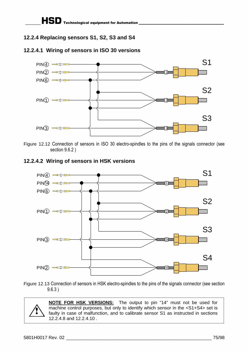
______HSD Technological equipment for Automation _____________________________________
5801H0017 Rev. 02 _________________________________________________________ 75/98
12.2.4 Replacing sensors S1, S2, S3 and S4
12.2.4.1 Wiring of sensors in ISO 30 versions
S1PIN 4
PIN 6
S2PIN 1
S3PIN 3
PIN 2
3
1
2
Figure 12.12 Connection of sensors in ISO 30 electro-spindles to the pins of the signals connector (seesection 9.6.2 )
12.2.4.2 Wiring of sensors in HSK versions
S1
S2
S44
1
2
PIN 4
PIN 6
PIN 1
PIN 2
14
S33PIN 3
PIN
Figure 12.13 Connection of sensors in HSK electro-spindles to the pins of the signals connector (see section9.6.3 )
NOTE FOR HSK VERSIONS: The output to pin “14” must not be used formachine control purposes, but only to identify which sensor in the <S1+S4> set isfaulty in case of malfunction, and to calibrate sensor S1 as instructed in sections12.2.4.8 and 12.2.4.10 .
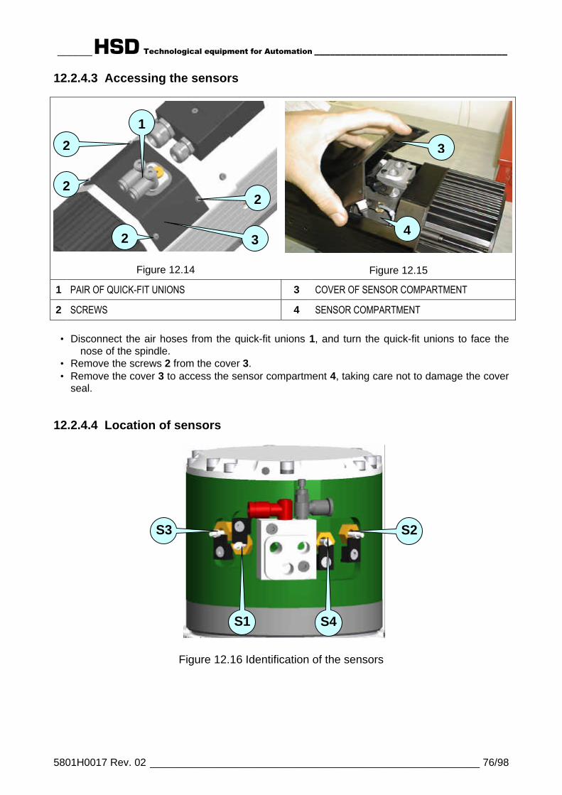
______HSD Technological equipment for Automation _____________________________________
5801H0017 Rev. 02 _________________________________________________________ 76/98
12.2.4.3 Accessing the sensors
Figure 12.14 Figure 12.15
1 PAIR OF QUICK-FIT UNIONS 3 COVER OF SENSOR COMPARTMENT
2 SCREWS 4 SENSOR COMPARTMENT
• Disconnect the air hoses from the quick-fit unions 1, and turn the quick-fit unions to face thenose of the spindle.
• Remove the screws 2 from the cover 3.• Remove the cover 3 to access the sensor compartment 4, taking care not to damage the cover
seal.
12.2.4.4 Location of sensors
Figure 12.16 Identification of the sensors
3
4
1
2
3
2
2
2
S1
S2
S4
S3
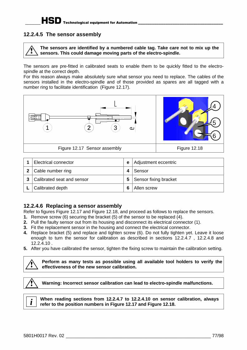
______HSD Technological equipment for Automation _____________________________________
5801H0017 Rev. 02 _________________________________________________________ 77/98
12.2.4.5 The sensor assembly
The sensors are identified by a numbered cable tag. Take care not to mix up thesensors. This could damage moving parts of the electro-spindle.
The sensors are pre-fitted in calibrated seats to enable them to be quickly fitted to the electro-spindle at the correct depth.For this reason always make absolutely sure what sensor you need to replace. The cables of thesensors installed in the electro-spindle and of those provided as spares are all tagged with anumber ring to facilitate identification (Figure 12.17).
e
L
1 3
3
22
Figure 12.17 Sensor assembly Figure 12.18
1 Electrical connector e Adjustment eccentric
2 Cable number ring 4 Sensor
3 Calibrated seat and sensor 5 Sensor fixing bracket
L Calibrated depth 6 Allen screw
12.2.4.6 Replacing a sensor assemblyRefer to figures Figure 12.17 and Figure 12.18, and proceed as follows to replace the sensors.1. Remove screw (6) securing the bracket (5) of the sensor to be replaced (4).2. Pull the faulty sensor out from its housing and disconnect its electrical connector (1).3. Fit the replacement sensor in the housing and connect the electrical connector.4. Replace bracket (5) and replace and tighten screw (6). Do not fully tighten yet. Leave it loose
enough to turn the sensor for calibration as described in sections 12.2.4.7 , 12.2.4.8 and12.2.4.10 .
5. After you have calibrated the sensor, tighten the fixing screw to maintain the calibration setting.
Perform as many tests as possible using all available tool holders to verify theeffectiveness of the new sensor calibration.
Warning: Incorrect sensor calibration can lead to electro-spindle malfunctions.
i When reading sections from 12.2.4.7 to 12.2.4.10 on sensor calibration, alwaysrefer to the position numbers in Figure 12.17 and Figure 12.18.
4
5
6

______HSD Technological equipment for Automation _____________________________________
5801H0017 Rev. 02 _________________________________________________________ 78/98
12.2.4.7 Calibrating sensors S1, S2, and S3 on ISO 30 electro-spindlesWhen you have replaced the sensor as instructed in section 12.2.4.6 , proceed as follows tocalibrate it.1. Check whether the signal output from the sensor corresponds to that specified in section 11.6.1
in the table for the sensor you are calibrating. (See Figure 13.1 for sensor S3.)2. If it does not, turn the sensor seat (4) until you obtain the output specified in the table for the
sensor you are calibrating. Hold the sensor in this position and tighten the fixing screw (6).
12.2.4.8 Calibrating sensors S1, S2, S3 and S4 on HSK F63 electro-spindles
iA kit of gauges and shims is available to assist in calibrating HSK F63 sensors.Their use is described in sections 12.2.4.9 and 12.2.4.10 .The kit makes calibration not only quicker but more precise too. HSD stronglyrecommends the use of this kit, given the importance that correct sensor calibrationhas for machining safety.
12.2.4.8.1 Procedure for S1When you have replaced the sensor as instructed in section 12.2.4.6 , proceed as follows tocalibrate it.1. Check whether the signal output from sensor S1 corresponds to that specified in the table
below.
CONDITION OUTPUT S1Tool holder locked +24 V
No tool holder 0 VTool holder ejected
(collet open) 0 V
2. Turn the spindle shaft by hand and check whether the conditions in the table are fulfilledthroughout the 360° of a complete revolution.
3. If they are not, turn the sensor seat (4) until you obtain the output specified in the table. Holdthe sensor in this position and tighten the fixing screw (6).
12.2.4.8.2 Procedure for S2
A
B
A Ejector XB Reference measurement X
Figure 12.19
When you have replaced the sensor as instructed in section 12.2.4.6 , proceed as follows tocalibrate it.
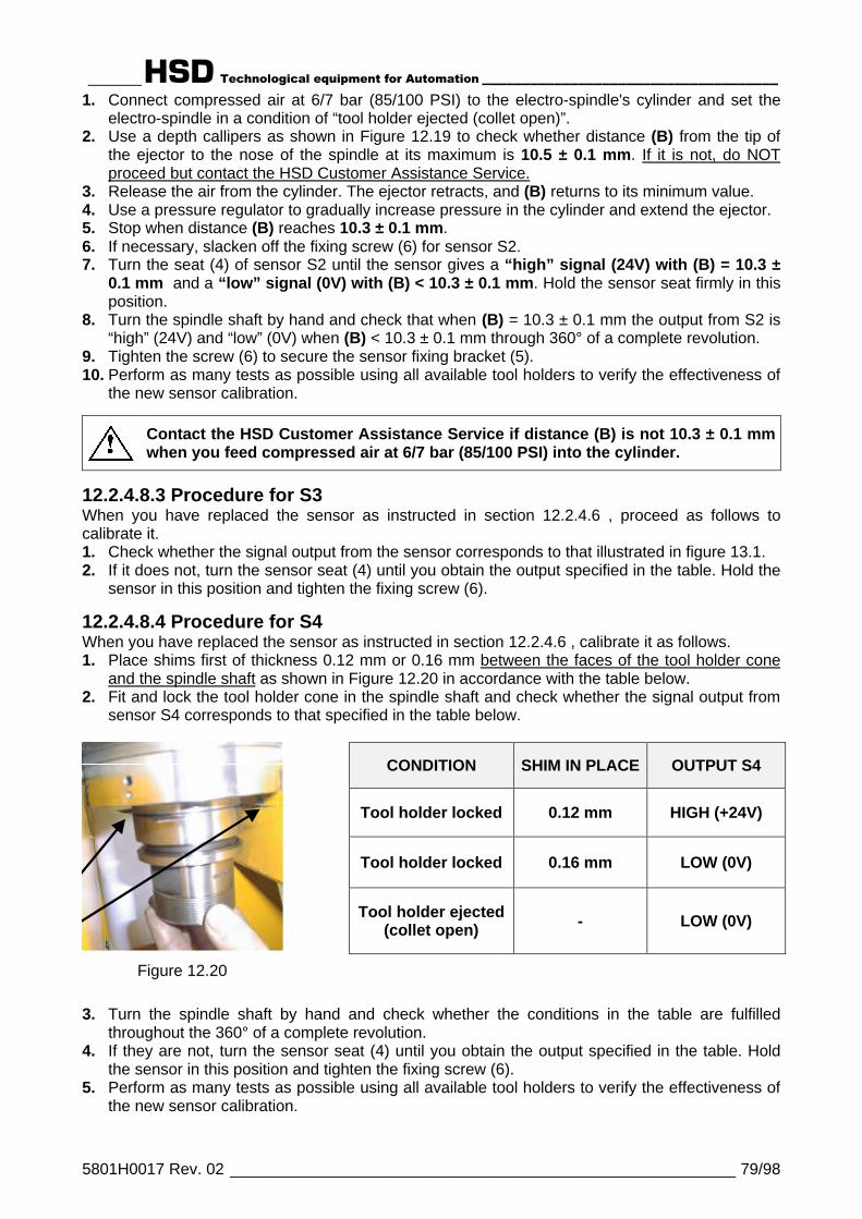
______HSD Technological equipment for Automation _____________________________________
5801H0017 Rev. 02 _________________________________________________________ 79/98
1. Connect compressed air at 6/7 bar (85/100 PSI) to the electro-spindle's cylinder and set theelectro-spindle in a condition of “tool holder ejected (collet open)”.
2. Use a depth callipers as shown in Figure 12.19 to check whether distance (B) from the tip ofthe ejector to the nose of the spindle at its maximum is 10.5 ± 0.1 mm. If it is not, do NOTproceed but contact the HSD Customer Assistance Service.
3. Release the air from the cylinder. The ejector retracts, and (B) returns to its minimum value.4. Use a pressure regulator to gradually increase pressure in the cylinder and extend the ejector.5. Stop when distance (B) reaches 10.3 ± 0.1 mm.6. If necessary, slacken off the fixing screw (6) for sensor S2.7. Turn the seat (4) of sensor S2 until the sensor gives a “high” signal (24V) with (B) = 10.3 ±
0.1 mm and a “low” signal (0V) with (B) < 10.3 ± 0.1 mm. Hold the sensor seat firmly in thisposition.
8. Turn the spindle shaft by hand and check that when (B) = 10.3 ± 0.1 mm the output from S2 is“high” (24V) and “low” (0V) when (B) < 10.3 ± 0.1 mm through 360° of a complete revolution.
9. Tighten the screw (6) to secure the sensor fixing bracket (5).10. Perform as many tests as possible using all available tool holders to verify the effectiveness of
the new sensor calibration.
Contact the HSD Customer Assistance Service if distance (B) is not 10.3 ± 0.1 mmwhen you feed compressed air at 6/7 bar (85/100 PSI) into the cylinder.
12.2.4.8.3 Procedure for S3When you have replaced the sensor as instructed in section 12.2.4.6 , proceed as follows tocalibrate it.1. Check whether the signal output from the sensor corresponds to that illustrated in figure 13.1.2. If it does not, turn the sensor seat (4) until you obtain the output specified in the table. Hold the
sensor in this position and tighten the fixing screw (6).
12.2.4.8.4 Procedure for S4When you have replaced the sensor as instructed in section 12.2.4.6 , calibrate it as follows.1. Place shims first of thickness 0.12 mm or 0.16 mm between the faces of the tool holder cone
and the spindle shaft as shown in Figure 12.20 in accordance with the table below.2. Fit and lock the tool holder cone in the spindle shaft and check whether the signal output from
sensor S4 corresponds to that specified in the table below.
CONDITION SHIM IN PLACE OUTPUT S4
Tool holder locked 0.12 mm HIGH (+24V)
Tool holder locked 0.16 mm LOW (0V)
Tool holder ejected(collet open) - LOW (0V)
Figure 12.20
3. Turn the spindle shaft by hand and check whether the conditions in the table are fulfilledthroughout the 360° of a complete revolution.
4. If they are not, turn the sensor seat (4) until you obtain the output specified in the table. Holdthe sensor in this position and tighten the fixing screw (6).
5. Perform as many tests as possible using all available tool holders to verify the effectiveness ofthe new sensor calibration.

______HSD Technological equipment for Automation _____________________________________
5801H0017 Rev. 02 _________________________________________________________ 80/98
12.2.4.9 Gauge and shim kit for calibrating S1 and S4 sensors on HSK F63electro-spindles (HSD code 3811H0110)
A Shim for calibrating sensor S1 (0.04 mm)
B Shim for calibrating sensor S4 (0.12 mm)
C Shim for calibrating sensor S4 (0.16 mm)
D Gauge for calibrating sensor S1 (14.29 mm)
E Gauge for calibrating sensor S4 (14.13 mm)
Figure 12.21 Gauge and shim kit for sensors on F63 electro-spindles, HSD 3811H0110
A gauge and shim kit, HSD code 3811H0110, is available for calibrating the sensors on HSK F63electro-spindles.This kit allows you to set HSK collets at exactly the right position for sensor calibration. This makescalibration a lot quicker and more precise too. The gauges are manufactured to far greaterprecision than standard tool holders.
It is possible to calibrate the sensors without this kit, proceeding as described in section 12.2.4.8 .HSD nevertheless strongly recommends the use of it, given the importance that correct sensorcalibration has for machining safety.
The gauges and shims shown in Figure 12.21 have their size punched on them or marked on thelabel of the bag containing them.
12.2.4.10 Calibrating sensors S1 and S4 on F63 HSK electro-spindles usingthe 3811H0110 kit
Figure 12.22 Using the gauge as a tool holder,with or without shims (Figure12.23) according to the table insections 12.2.4.10.1 and12.2.4.10.2
Figure 12.23 Placing a shim between thefaces of the gauge and spindleshaft
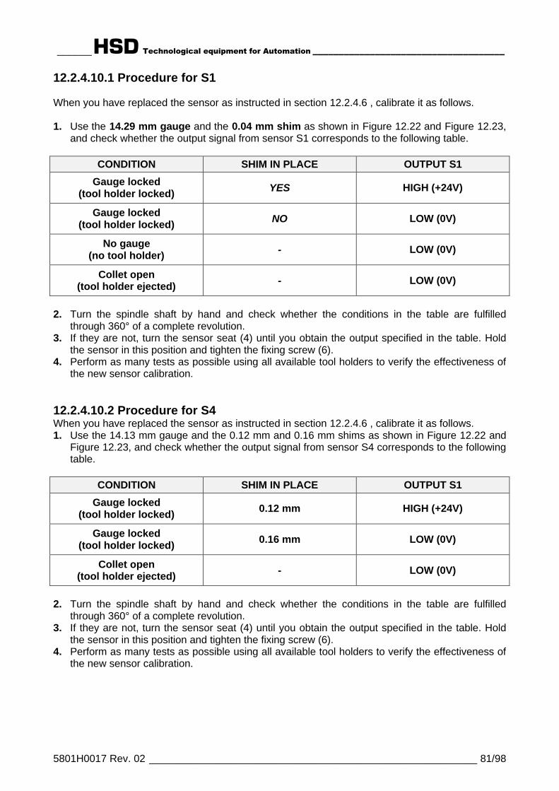
______HSD Technological equipment for Automation _____________________________________
5801H0017 Rev. 02 _________________________________________________________ 81/98
12.2.4.10.1 Procedure for S1
When you have replaced the sensor as instructed in section 12.2.4.6 , calibrate it as follows.
1. Use the 14.29 mm gauge and the 0.04 mm shim as shown in Figure 12.22 and Figure 12.23,and check whether the output signal from sensor S1 corresponds to the following table.
CONDITION SHIM IN PLACE OUTPUT S1
Gauge locked(tool holder locked) YES HIGH (+24V)
Gauge locked(tool holder locked) NO LOW (0V)
No gauge(no tool holder) - LOW (0V)
Collet open(tool holder ejected) - LOW (0V)
2. Turn the spindle shaft by hand and check whether the conditions in the table are fulfilledthrough 360° of a complete revolution.
3. If they are not, turn the sensor seat (4) until you obtain the output specified in the table. Holdthe sensor in this position and tighten the fixing screw (6).
4. Perform as many tests as possible using all available tool holders to verify the effectiveness ofthe new sensor calibration.
12.2.4.10.2 Procedure for S4When you have replaced the sensor as instructed in section 12.2.4.6 , calibrate it as follows.1. Use the 14.13 mm gauge and the 0.12 mm and 0.16 mm shims as shown in Figure 12.22 and
Figure 12.23, and check whether the output signal from sensor S4 corresponds to the followingtable.
CONDITION SHIM IN PLACE OUTPUT S1
Gauge locked(tool holder locked) 0.12 mm HIGH (+24V)
Gauge locked(tool holder locked) 0.16 mm LOW (0V)
Collet open(tool holder ejected) - LOW (0V)
2. Turn the spindle shaft by hand and check whether the conditions in the table are fulfilledthrough 360° of a complete revolution.
3. If they are not, turn the sensor seat (4) until you obtain the output specified in the table. Holdthe sensor in this position and tighten the fixing screw (6).
4. Perform as many tests as possible using all available tool holders to verify the effectiveness ofthe new sensor calibration.

______HSD Technological equipment for Automation _____________________________________
5801H0017 Rev. 02 _________________________________________________________ 82/98
12.2.5 Replacing the cylinder assembly
1 Open the sensor compartment as instructedin section 12.2.4.3 .
2 Disconnect all the electrical connectors.
3 IMPORTANT:
Before you disconnect hoses A and D(see step 4 below) tag them or markthem with adhesive tape, so that youcan recognize which is which in therest of the procedure.
A Compressed air line for optionalfunctions
B Quick-fit union
C Quick-fit union with pressureregulator
D Compressed air line for internalpressurization
E Compressed air inlet for conecleaning and pressurization
4
5
• Clearly mark hoses A and D as instructedin step 3.
• Disconnect hoses A and D from unions Band C.
• Remove the two fixing screws from blockG.
• Remove block G taking care not to lose ordamage the seals.
• Remove the four screws F.
• Remove the cooling fan cover in thedirection shown by the arrow.
A DB C
E
G
F

______HSD Technological equipment for Automation _____________________________________
5801H0017 Rev. 02 _________________________________________________________ 83/98
6 Remove only the six screws shown torelease the cylinder.
7 Fit the new cylinder using the six screwsremoved in step 6.
C Quick-fit union with pressureregulator
D Compressed air line internalpressurization
E Compressed air inlet for conecleaning and pressurization
H Connection hose
M Pressure gauge
8
C Quick-fit union with pressureregulator
N Adjuster
P Lock nut
9• Fit a pressure gauge M as shown in step
8 to measure the outlet pressure fromunion C.
• Connect an air supply at 4 bar (58 PSI) toE.
• Turn adjuster N until the pressure on thegauge reads 0.8 bar (11.6 PSI).
• Tighten lock nut P to lock the adjustment.
• Disconnect the pressure gauge M andhoses D and H from union C.
N
P
C
DC
E
M
H
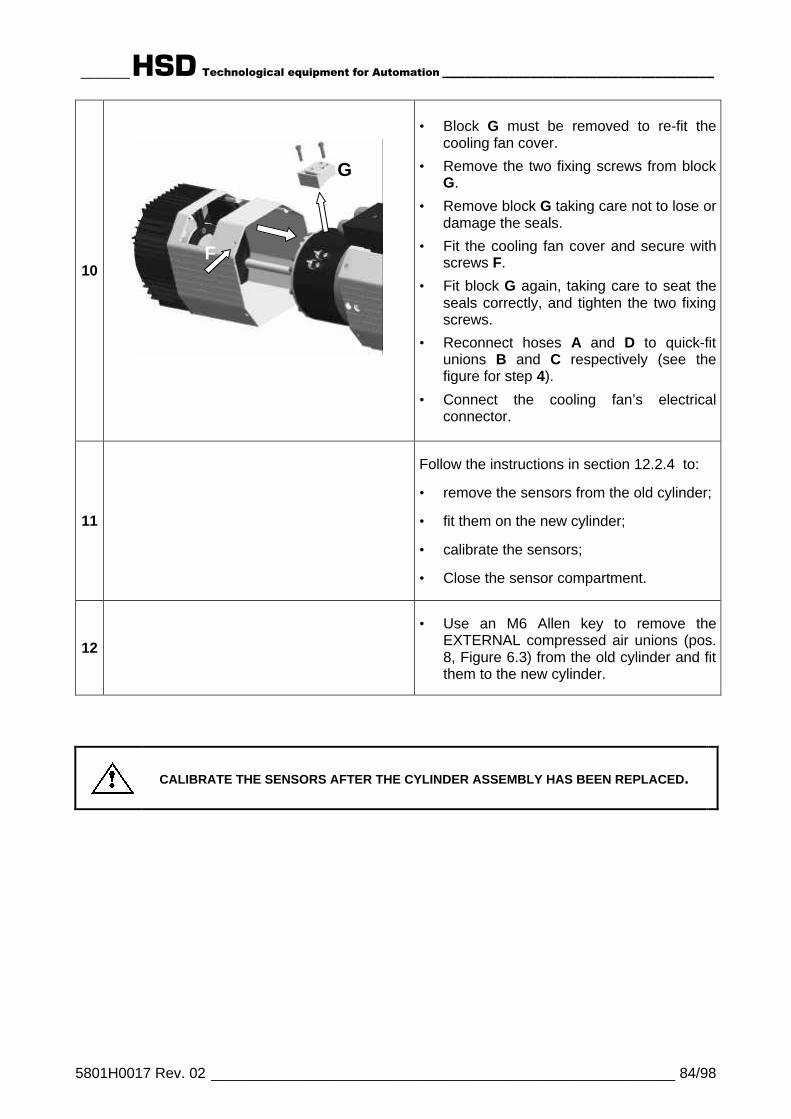
______HSD Technological equipment for Automation _____________________________________
5801H0017 Rev. 02 _________________________________________________________ 84/98
10
• Block G must be removed to re-fit thecooling fan cover.
• Remove the two fixing screws from blockG.
• Remove block G taking care not to lose ordamage the seals.
• Fit the cooling fan cover and secure withscrews F.
• Fit block G again, taking care to seat theseals correctly, and tighten the two fixingscrews.
• Reconnect hoses A and D to quick-fitunions B and C respectively (see thefigure for step 4).
• Connect the cooling fan’s electricalconnector.
11
Follow the instructions in section 12.2.4 to:
• remove the sensors from the old cylinder;
• fit them on the new cylinder;
• calibrate the sensors;
• Close the sensor compartment.
12
• Use an M6 Allen key to remove theEXTERNAL compressed air unions (pos.8, Figure 6.3) from the old cylinder and fitthem to the new cylinder.
CALIBRATE THE SENSORS AFTER THE CYLINDER ASSEMBLY HAS BEEN REPLACED.
G
F

______HSD Technological equipment for Automation _____________________________________
5801H0017 Rev. 02 _________________________________________________________ 85/98
§ 13 ACCESSORIES AND OPTIONS
BEFORE STARTING ANY WORK ON THE ELECTRO-SPINDLE, READ ANDFOLLOW ALL THE SAFETY PRECAUTIONS AND MAINTENANCE SAFETYWARNINGS.SEE IN PARTICULAR CHAPTER § 5 AND PAGES 66 AND 71 OF CHAPTER § 12.
On request, the electro-spindle can be fitted with the following accessories and options:
1. "Spindle shaft stopped" sensor S3 (See section 13.1 )2. Bearing temperature sensor (See section 13.2 )3. Belt driven C axis (See section 13.3 )4. Gear driven C axis (See section 13.3 )5. Forced air cooling (See section 13.4 )
13.1 "SPINDLE SHAFT STOPPED" SENSOR S3The “SPINDLE SHAFT STOPPED” sensor outputs two “ON” and two “OFF” pulses per shaftrevolution. It remains permanently “ON” at high speeds.
+ 24 V
0 V
0 girirev
1
Figure 13.1 Output from sensor S3
See section 7.7.4 for the sensor's electrical specifications.See section 12.2.4 to install and calibrate the sensor. Make sure that output is as specified inFigure 13.1.
i Ignore the output of S3 during tool changes.
13.2 BEARING TEMPERATURE SENSORA temperature sensor (PT 1000 type) can be fitted to the electro-spindle to detect high bearingtemperatures.The sensor can be connected to any numeric controller capable of interfacing with a temperaturesensitive resistance (analog input).
1 Seat for sensor hole(Pos. 4 in Figure 13.3)
2 Electrical connector
Figure 13.2

______HSD Technological equipment for Automation _____________________________________
5801H0017 Rev. 02 _________________________________________________________ 86/98
13.2.1 Installing the bearing temperature sensor
Figure 13.3
3 Electrical connector for bearing temperaturesensor (in shrink wrapped protective sheath)
4 Sensor hole with protective cover secured bytwo screws
5 Connector for sensor SC of the gear driven Caxis (optional C axis)
Take care not to mix up connector 3 with connector 5.
• Remove the cover fixing screws and remove the cover from the temperature sensor hole 4.• Fit the seat 1 in the hole 4.• Fix the sensor in place with the two screws previously removed from the cover.• Remove the shrink wrapped sheath from connector 3.• Connect connector 2 to connector 3.
13.2.2 Characteristic curve of the temperature sensor referred to 1 mA
Res
ista
nce
in O
hms
0
250
500
750
1000
1250
1500
1750
2000
2250
2500
-60 -40 -20 0 20 40 60 80 100 120 140 160
Temperature in °C
Resistance +/- 2% (Ohm) 815 886 961 1000 1040 1122 1208 1299 1392 1490 1591 1696Temperature +/- 5% (°C) 0 10 20 25 30 40 50 60 70 80 90 100Temperature +/- 5% (°F) 32 50 68 77 86 104 122 140 158 176 194 212

______HSD Technological equipment for Automation _____________________________________
5801H0017 Rev. 02 _________________________________________________________ 87/98
13.3 “C” AXIS UNITES919 and ES915 variants can be fitted with a C Axis unit.
The C axis unit rotates heads, gearboxes etc. fixed to the electro-spindle through 360° on theassembly plane by means of a quick lock device and specially shaped drive pin.Rotational movement is powered by a servomotor, rigidly mounted in line with a low-backlashepicyclic gearbox.A PNP, NC inductive sensor, “SC”, provides a zero position reference signal and allows theassembly to be positioned quickly and accurately for tool release into the tool magazine.C axis units can be Gear driven or Belt driven. Gear driven C axis units are available as separateoptionals for all “Short Nose” and “Long Nose” variants. Belt driven C axis units are not availableas separate optionals, but come pre-fitted, and only to ES919 ISO30 (7 kW or 8 kW version, 2poles) Short Nose variants.Choice of the C axis servomotor is left to the customer. The mounting flanges for Belt driven C axisunits are shown in section 7.6.2 .
i All parts of the C axis are lubricated for life and are maintenance free.
13.3.1 Belt driven “C” axis unit
i For the overall dimensions and technical specifications of belt drivenC axis unit, see section 7.6 .
13.3.2 Gear driven “C” axis unitHelical gears with automatic backlash elimination.For installation instructions and technical specifications, see the manual delivered with the unit oravailable from the HSD Technical Assistance Service (code HSD 5801H0019).Main specifications for a servomotor giving 0.64 Nm at 3000 rpm (*)
Rated torque 67 Nm (*)Starting torque 105 Nm (*)Overall gear ratio 1 / 123Total mechanical efficiency 0,85Epicyclic gear backlash 3’Positioning precision 5’Gearbox input rpm 3000 rpm (4000 rpm max)Rated gearbox input torque 2.5 NmStarting gearbox input torque 4 NmWeight 10 Kg (without servomotor)
(*) Specifications depend on the choice of servomotor.

______HSD Technological equipment for Automation _____________________________________
5801H0017 Rev. 02 _________________________________________________________ 88/98
13.3.3 SC sensor for the belt driven “C” axis unit
Sensor type: PNP proximity; NC (Normally Closed)
Voltage 10 - 30 V (DC)
Maximum load 200 mA
No-load consumption < 10 mA
Rated read distance 0.8 mm
The C axis unit comes complete with a PNP NC (Normally Closed) inductive sensor designatedSC.The closing of the sensor contacts signals the zero reference position and allows the assembly tobe positioned quickly and accurately for tool release into the tool magazine.The zero position is the position at which the hole for the shaped drive pin aligns with sensor SC,as shown in the detail inside the white circle in Figure 13.4.
CONDITION STATE OF CONTACTS
Zero position Closed
All other positions Open
Figure 13.4 The zero reference position
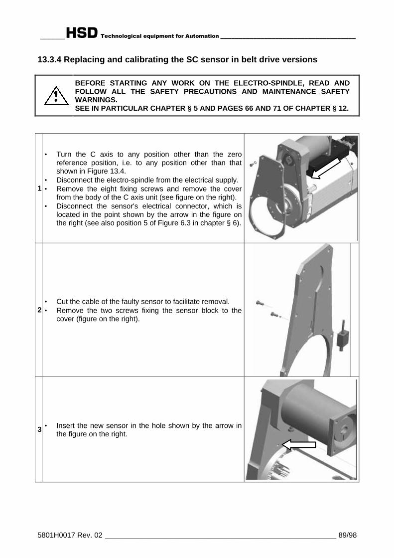
______HSD Technological equipment for Automation _____________________________________
5801H0017 Rev. 02 _________________________________________________________ 89/98
13.3.4 Replacing and calibrating the SC sensor in belt drive versions
BEFORE STARTING ANY WORK ON THE ELECTRO-SPINDLE, READ ANDFOLLOW ALL THE SAFETY PRECAUTIONS AND MAINTENANCE SAFETYWARNINGS.SEE IN PARTICULAR CHAPTER § 5 AND PAGES 66 AND 71 OF CHAPTER § 12.
1.
• Turn the C axis to any position other than the zeroreference position, i.e. to any position other than thatshown in Figure 13.4.
• Disconnect the electro-spindle from the electrical supply.• Remove the eight fixing screws and remove the cover
from the body of the C axis unit (see figure on the right).• Disconnect the sensor's electrical connector, which is
located in the point shown by the arrow in the figure onthe right (see also position 5 of Figure 6.3 in chapter § 6).
2.• Cut the cable of the faulty sensor to facilitate removal.• Remove the two screws fixing the sensor block to the
cover (figure on the right).
3.• Insert the new sensor in the hole shown by the arrow inthe figure on the right.

______HSD Technological equipment for Automation _____________________________________
5801H0017 Rev. 02 _________________________________________________________ 90/98
4.
• Apply some Loctite 243 or equivalent medium strengththread locking compound to the threads of the sensor.
• Screw the sensor into the side of the sensor block withthe largest hole.
• Screw the sensor in until you achieve the protrusionshown in the figure on the right.
• Wait for the thread locking compound to set incompliance with the manufacturer's instructions.
5.• Fit the assembled sensor + sensor block to the cover
(figure on the right), but leave the screws loose enoughfor the sensor block to move.
6.
• Apply silicon sealant to the sensor cable hole.• Check that the C axis unit is still in a position other than
the zero position, i.e. that the drive pin hole is not in theposition shown in Figure 13.4. Turn the C axis unit ifnecessary.
• Fit the cover back on the body of the C axis unit. Fit andtighten all the fixing screws (figure on the right).
7.
• Adjust the sensor read distance using either“PROCEDURE_A” or “PROCEDURE_B”:
PROCEDURE A• Place a shim of 0.2 mm between the pulley and the
sensor.• Push the sensor against the pulley and into firm contact
with the shim.• Tighten the two sensor block fixing screws.• Remove the shim.
PROCEDURE B• Push the sensor against the pulley and check that the
sensor contacts are open.• Slowly slide the sensor away from the pulley until the
contacts close.• Slowly slide the sensor towards the pulley again until the
contacts just open.• Tighten the two sensor block fixing screws.
8.
• Re-connect the electro-spindle's electrical connections.• Turn the C axis unit, and check that the contacts of
sensor SC remain closed at all positions other than zeroposition (see Figure 13.4) when they must open.
• Check sensor functioning at as many axis positions aspractical.
0,2
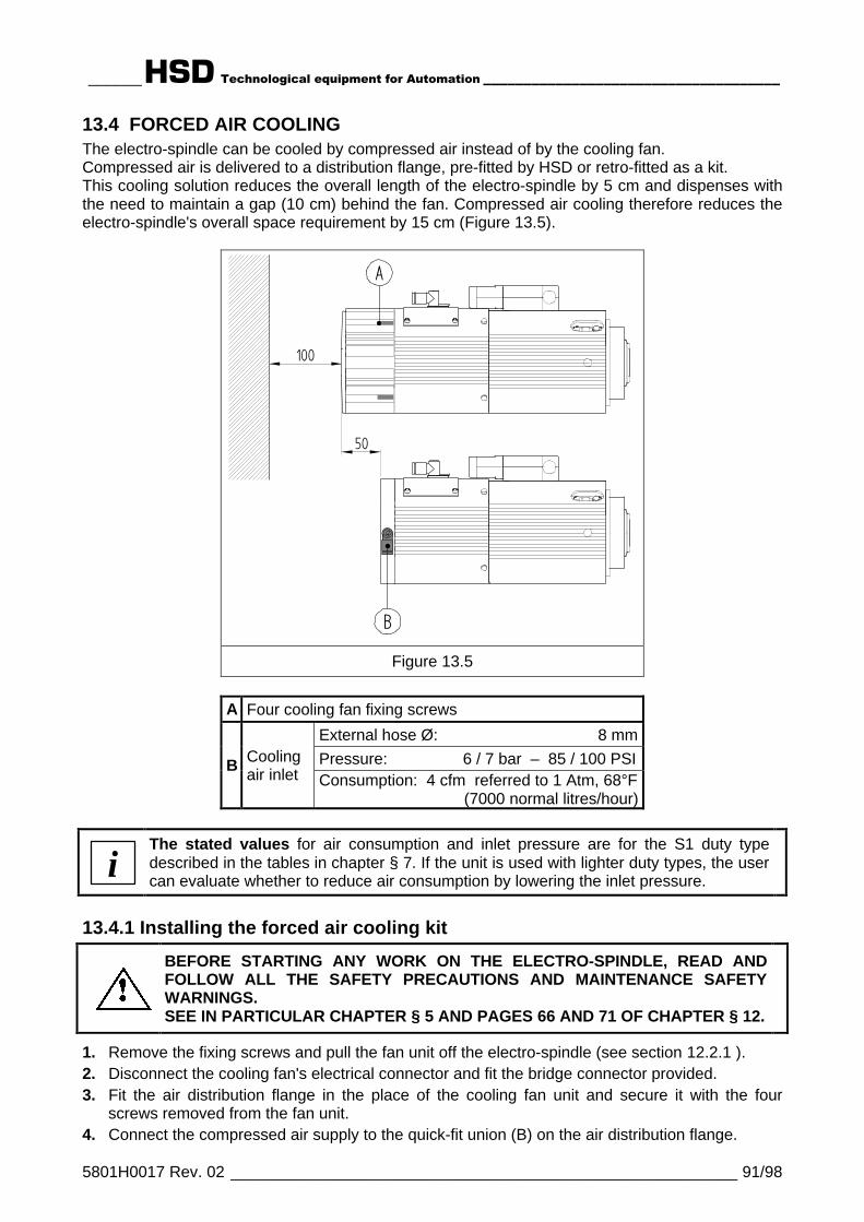
______HSD Technological equipment for Automation _____________________________________
5801H0017 Rev. 02 _________________________________________________________ 91/98
13.4 FORCED AIR COOLINGThe electro-spindle can be cooled by compressed air instead of by the cooling fan.Compressed air is delivered to a distribution flange, pre-fitted by HSD or retro-fitted as a kit.This cooling solution reduces the overall length of the electro-spindle by 5 cm and dispenses withthe need to maintain a gap (10 cm) behind the fan. Compressed air cooling therefore reduces theelectro-spindle's overall space requirement by 15 cm (Figure 13.5).
A
50
100
B
Figure 13.5
A Four cooling fan fixing screws
External hose Ø: 8 mmPressure: 6 / 7 bar – 85 / 100 PSIB Cooling
air inlet Consumption: 4 cfm referred to 1 Atm, 68°F(7000 normal litres/hour)
iThe stated values for air consumption and inlet pressure are for the S1 duty typedescribed in the tables in chapter § 7. If the unit is used with lighter duty types, the usercan evaluate whether to reduce air consumption by lowering the inlet pressure.
13.4.1 Installing the forced air cooling kit
BEFORE STARTING ANY WORK ON THE ELECTRO-SPINDLE, READ ANDFOLLOW ALL THE SAFETY PRECAUTIONS AND MAINTENANCE SAFETYWARNINGS.SEE IN PARTICULAR CHAPTER § 5 AND PAGES 66 AND 71 OF CHAPTER § 12.
1. Remove the fixing screws and pull the fan unit off the electro-spindle (see section 12.2.1 ).2. Disconnect the cooling fan's electrical connector and fit the bridge connector provided.3. Fit the air distribution flange in the place of the cooling fan unit and secure it with the four
screws removed from the fan unit.4. Connect the compressed air supply to the quick-fit union (B) on the air distribution flange.

______HSD Technological equipment for Automation _____________________________________
5801H0017 Rev. 02 _________________________________________________________ 92/98
§ 14 TROUBLE SHOOTING
BEFORE STARTING ANY WORK ON THE ELECTRO-SPINDLE, READ ANDFOLLOW ALL THE SAFETY PRECAUTIONS AND MAINTENANCE SAFETYWARNINGS.
PROBLEM PROBABLE CAUSE CORRECTIVE ACTION
There is no power
• Check the mains powersupply.
• Check all power terminals.• Check all electrical cables and
connections for breaks.
No tool holder is fitted Fit a tool holder.
The tool holder not correctlyseated
See “The tool holder is notlocked” below.
The thermal switch has tripped
Wait for the electro-spindle to cooldown and the thermal switch willautomatically reset.If the thermal switch tripsfrequently, see “The electro-spindle overheats” below.
The inverter switch has tripped
Consult the inverter's own manualor contact the invertermanufacturer.On electro-spindles withconfigurable power terminalsonly: see section 9.6.6 and checkthat the power terminals areconfigured correctly for the mainspower rating.
Sensor S1 (ISO 30) or sensorseries <S1+S4> (HSK) isdisconnected or faulty
• Check the sensor connectors.• Check the sensor cables for
breaks.• Calibrate the sensors as
instructed in section 12.2.4 .• Replace any faulty sensors as
instructed in section 12.2.4 .
The electro-spindle doesnot turn
There is no electro-spindleenabling signal
Consult the manuals or contactthe manufacturers of themachine, numeric controller, andinverter.

______HSD Technological equipment for Automation _____________________________________
5801H0017 Rev. 02 _________________________________________________________ 93/98
There is dirt or foreignbodies between the toolholder and the spindleshaft housing
Remove any large foreign bodiesand clean the tool holder cone andspindle housing as instructed insection 12.1.2 .
The tool holder cone is notof the right type
Choose a tool holder as instructedin sections 11.4.1 (ISO 30), 11.4.2(HSK) and 11.4.3 (all).
There is insufficient airpressure to open the collet
• Check the air pressure settingsin accordance with section 9.4
• Check the compressed airsystem for leaks and pressurelosses.
The electro-spindle is notaligned with the tool holdermagazine
Consult the machine's own manualor contact the machinemanufacturer.
Sensor S2 is disconnectedor faulty
• Check the sensor connectors.• Check the sensor cables for
breaks.• Calibrate the sensors as
instructed in section 12.2.4 .• Replace any faulty sensors as
instructed in section 12.2.4 .
The tool holder is not locked
There is a control errorConsult the machine's own manualor contact the machinemanufacturer.
There is insufficient airpressure
• Check the air pressure settingsin accordance with section 9.4
• Check the compressed airsystem for leaks and pressurelosses.The tool holder is not ejected
There is no ejectionenabling signal
Consult the manuals or contact themanufacturers of the machine,numeric controller, and inverter.
There is no air pressureinside the electro-spindle
There is insufficient airpressure or thecompressed air system isfaulty
• Check the air pressure settingsin accordance with section 9.4.
• Check the compressed airsystem for leaks and pressurelosses.
• Contact the HSD TechnicalAssistance Service.
One of the sensors does notgive the required output
A sensor is disconnectedor faulty
• Check the sensor connectors.• Check the sensor cables for
breaks.• Calibrate the sensors as
instructed in section 12.2.4 .• Replace any faulty sensors as
instructed in section 12.2.4 .
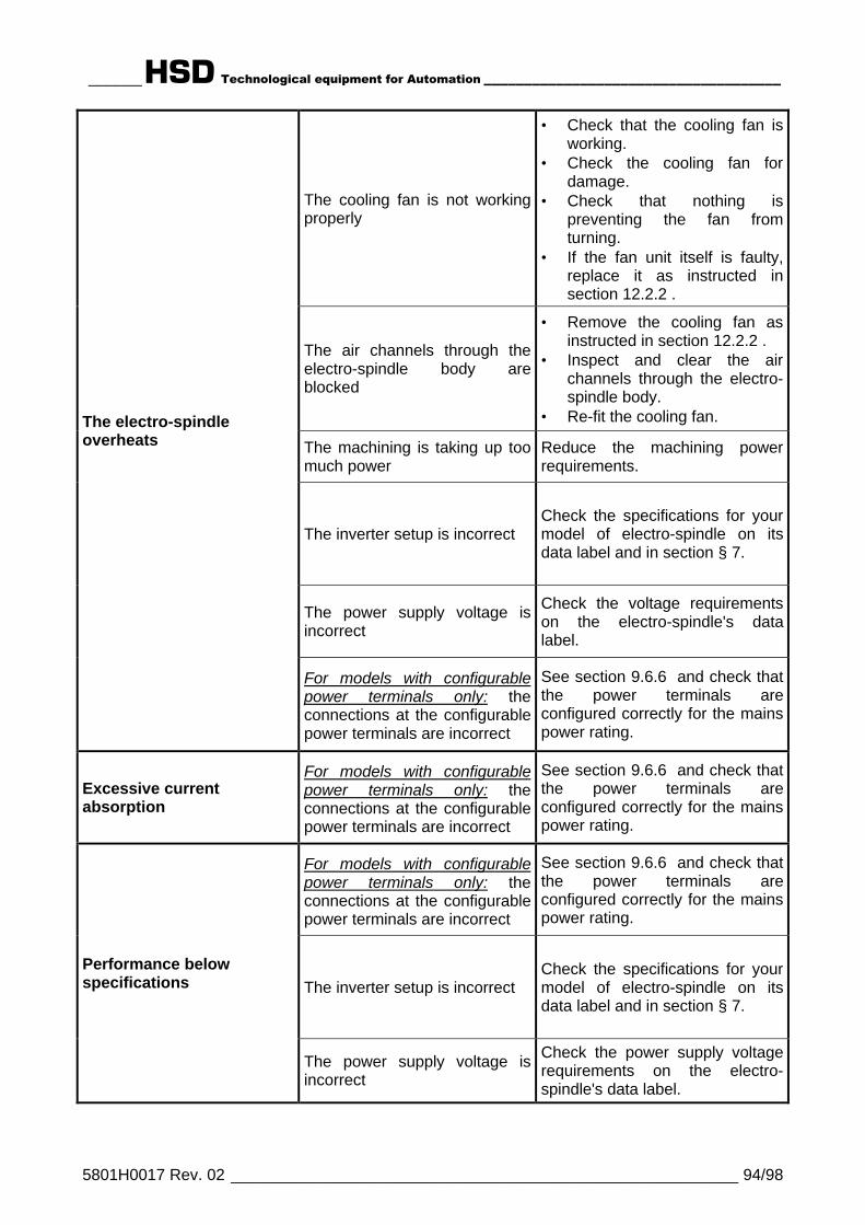
______HSD Technological equipment for Automation _____________________________________
5801H0017 Rev. 02 _________________________________________________________ 94/98
The cooling fan is not workingproperly
• Check that the cooling fan isworking.
• Check the cooling fan fordamage.
• Check that nothing ispreventing the fan fromturning.
• If the fan unit itself is faulty,replace it as instructed insection 12.2.2 .
The air channels through theelectro-spindle body areblocked
• Remove the cooling fan asinstructed in section 12.2.2 .
• Inspect and clear the airchannels through the electro-spindle body.
• Re-fit the cooling fan.
The machining is taking up toomuch power
Reduce the machining powerrequirements.
The inverter setup is incorrectCheck the specifications for yourmodel of electro-spindle on itsdata label and in section § 7.
The power supply voltage isincorrect
Check the voltage requirementson the electro-spindle's datalabel.
The electro-spindleoverheats
For models with configurablepower terminals only: theconnections at the configurablepower terminals are incorrect
See section 9.6.6 and check thatthe power terminals areconfigured correctly for the mainspower rating.
Excessive currentabsorption
For models with configurablepower terminals only: theconnections at the configurablepower terminals are incorrect
See section 9.6.6 and check thatthe power terminals areconfigured correctly for the mainspower rating.
For models with configurablepower terminals only: theconnections at the configurablepower terminals are incorrect
See section 9.6.6 and check thatthe power terminals areconfigured correctly for the mainspower rating.
The inverter setup is incorrectCheck the specifications for yourmodel of electro-spindle on itsdata label and in section § 7.
Performance belowspecifications
The power supply voltage isincorrect
Check the power supply voltagerequirements on the electro-spindle's data label.

______HSD Technological equipment for Automation _____________________________________
5801H0017 Rev. 02 _________________________________________________________ 95/98
The tool holder is not balanced
Choose a tool holder inaccordance with sections 11.4.1(ISO 30), 11.4.2 (HSK) and11.4.3 (all).
The tool is not balanced Choose a tool in accordancewith sections 11.4.4 and 11.5 .
There is dirt or foreign bodiesbetween the tool holder and thespindle shaft housing
Remove any large foreignbodies and clean the tool holdercone and spindle housing asinstructed in section 12.1.2 .
The inverter setup is incorrectCheck the specifications for yourmodel of electro-spindle on itsdata label and in section § 7.
The machining is taking up toomuch power
Reduce the machining powerrequirements.
The fixing bolts are loose Tighten the fixing bolts.
The electro-spindle vibrates
The bearings are worn ordamaged Replace the spindle shaft kit.
The bearings are noisy The bearings are worn ordamaged Replace the spindle shaft kit.
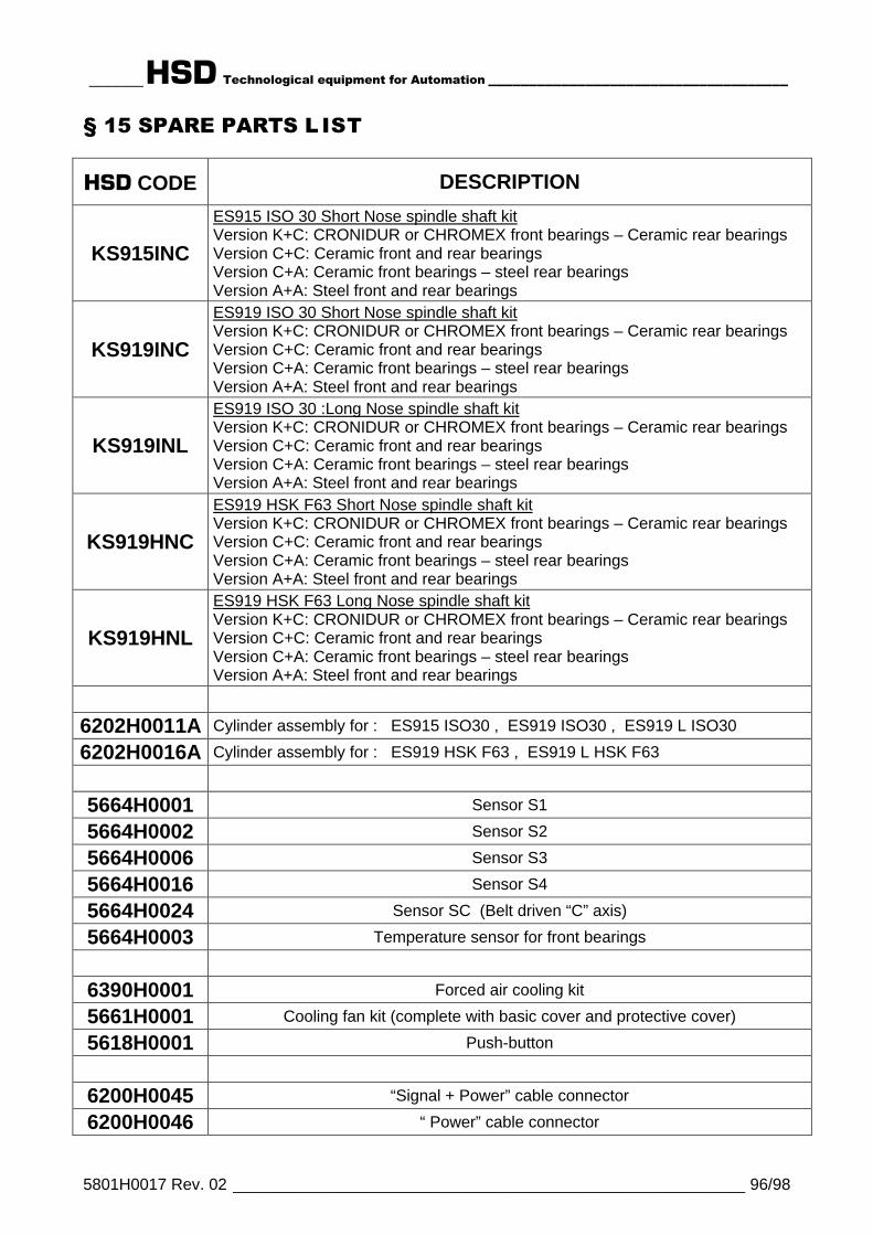
______HSD Technological equipment for Automation _____________________________________
5801H0017 Rev. 02 _________________________________________________________ 96/98
§ 15 SPARE PARTS L IST
HSD CODE DESCRIPTION
KS915INC
ES915 ISO 30 Short Nose spindle shaft kitVersion K+C: CRONIDUR or CHROMEX front bearings – Ceramic rear bearingsVersion C+C: Ceramic front and rear bearingsVersion C+A: Ceramic front bearings – steel rear bearingsVersion A+A: Steel front and rear bearings
KS919INC
ES919 ISO 30 Short Nose spindle shaft kitVersion K+C: CRONIDUR or CHROMEX front bearings – Ceramic rear bearingsVersion C+C: Ceramic front and rear bearingsVersion C+A: Ceramic front bearings – steel rear bearingsVersion A+A: Steel front and rear bearings
KS919INL
ES919 ISO 30 :Long Nose spindle shaft kitVersion K+C: CRONIDUR or CHROMEX front bearings – Ceramic rear bearingsVersion C+C: Ceramic front and rear bearingsVersion C+A: Ceramic front bearings – steel rear bearingsVersion A+A: Steel front and rear bearings
KS919HNC
ES919 HSK F63 Short Nose spindle shaft kitVersion K+C: CRONIDUR or CHROMEX front bearings – Ceramic rear bearingsVersion C+C: Ceramic front and rear bearingsVersion C+A: Ceramic front bearings – steel rear bearingsVersion A+A: Steel front and rear bearings
KS919HNL
ES919 HSK F63 Long Nose spindle shaft kitVersion K+C: CRONIDUR or CHROMEX front bearings – Ceramic rear bearingsVersion C+C: Ceramic front and rear bearingsVersion C+A: Ceramic front bearings – steel rear bearingsVersion A+A: Steel front and rear bearings
6202H0011A Cylinder assembly for : ES915 ISO30 , ES919 ISO30 , ES919 L ISO30
6202H0016A Cylinder assembly for : ES919 HSK F63 , ES919 L HSK F63
5664H0001 Sensor S1
5664H0002 Sensor S2
5664H0006 Sensor S3
5664H0016 Sensor S4
5664H0024 Sensor SC (Belt driven “C” axis)
5664H0003 Temperature sensor for front bearings
6390H0001 Forced air cooling kit
5661H0001 Cooling fan kit (complete with basic cover and protective cover)
5618H0001 Push-button
6200H0045 “Signal + Power” cable connector
6200H0046 “ Power” cable connector
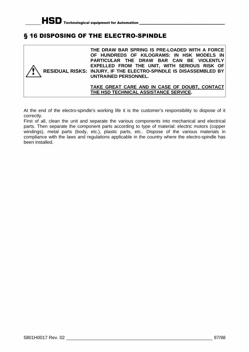
______HSD Technological equipment for Automation _____________________________________
5801H0017 Rev. 02 _________________________________________________________ 97/98
§ 16 DISPOSING OF THE ELECTRO-SPINDLE
RESIDUAL RISKS:
THE DRAW BAR SPRING IS PRE-LOADED WITH A FORCEOF HUNDREDS OF KILOGRAMS: IN HSK MODELS INPARTICULAR THE DRAW BAR CAN BE VIOLENTLYEXPELLED FROM THE UNIT, WITH SERIOUS RISK OFINJURY, IF THE ELECTRO-SPINDLE IS DISASSEMBLED BYUNTRAINED PERSONNEL.
TAKE GREAT CARE AND IN CASE OF DOUBT, CONTACTTHE HSD TECHNICAL ASSISTANCE SERVICE.
At the end of the electro-spindle's working life it is the customer’s responsibility to dispose of itcorrectly.First of all, clean the unit and separate the various components into mechanical and electricalparts. Then separate the component parts according to type of material: electric motors (copperwindings), metal parts (body, etc.), plastic parts, etc.. Dispose of the various materials incompliance with the laws and regulations applicable in the country where the electro-spindle hasbeen installed.

______HSD Technological equipment for Automation ____________________________________
5801H0017 Rev. 02 _________________________________________________________ 98/98
HSD S.p.a.
TECHNOLOGICAL EQUIPMENT FOR AUTOMATION
ï==ï==ï===K===Ü==ë==Ç==J==Ü==á==í==É==Å===K===Å==ç==ãï==ï==ï===K===Ü==ë==Ç==J==Ü==á==í==É==Å===K===Å==ç==ãï==ï==ï===K===Ü==ë==Ç==J==Ü==á==í==É==Å===K===Å==ç==ãï==ï==ï===K===Ü==ë==Ç==J==Ü==á==í==É==Å===K===Å==ç==ã
Via della Meccanica 1661100 PESARO (ITALIA)Loc. Chiusa di Ginestreto
UFFICIO COMMERCIALE / SALES DEPT.Tel. (+39)0721.439.612Fax (+39)0721.441.606E-mail [email protected]
SERVIZIO ASSISTENZA CLIENTI // CUSTOMER CARE ASSISTANCETel. (+39)0721.439.638Fax (+39)0721.441.606E-mail [email protected]
HSD DeutschlandHSD DeutschlandHSD DeutschlandHSD Deutschland GmbHBrückenstrasse 2D-73333 GingenTel. +49(0)7162 / 9323436Fax +49(0)7162 / 9323439E-mail [email protected]
HSD USAHSD USAHSD USAHSD USA Inc.3764 SW, 30th AvenueHollywood, Florida 33312 USAPhone no. (+1) 954 587 1991Fax (+1) 954 587 8338E-mail [email protected]
www.hsdusa.com


![?jcmn gifiac[m^iMof - estudogeral.sib.uc.pt · 0 ?JCMN?GIFIAC;M>IMOF =;JãNOFI24 Nl[hmc _mhiÍJlial_mmiÎ^[=cpcfct[ i4 n_ilct[ imi\l_[bcmn lc[&[jl nc][_[nl[^c i,0+?\l[bcgGiim[J[ln_-ÉA_i'jif](https://static.fdocuments.net/doc/165x107/5bf9867609d3f266768c5fbd/jcmn-gifiacmimof-0-jcmngifiacmimof-janofi24-nlhmc-mhiijlialmmiicpcfct.jpg)