5800V Series Stackable Fibre Channel Switch...
436
59263-02 B User’s Guide Command Line Interface 5800V Series Stackable Fibre Channel Switch Firmware Version 8.0
Transcript of 5800V Series Stackable Fibre Channel Switch...
59263-02 B
User’s GuideCommand Line Interface
5800V Series Stackable Fibre Channel Switch
Firmware Version 8.0
ii 59263-02 B
User’s Guide Command Line Interface
5800V Series Stackable Fibre Channel Switch
Information furnished in this manual is believed to be accurate and reliable. However, QLogic Corporation assumes no responsibility for its use, nor for any infringements of patents or other rights of third parties which may result from its use. QLogic Corporation reserves the right to change product specifications at any time without notice. Applications described in this document for any of these products are for illustrative purposes only. QLogic Corporation makes no representation nor warranty that such applications are suitable for the specified use without further testing or modification. QLogic Corporation assumes no responsibility for any errors that may appear in this document.
This switch is covered by one or more of the following patents: 6697359; other patents pending.
Document Revision History
Revision A, October, 2008
Revision B, November 2011
Changes Pages Affected
Support for transparent routing. 5-8, 5-15, 13-109, 13-214, 13-218
Support for Internet Key Exchange and Public Key Infrastructure
3-7, 3-8, 3-9, 3-10, 3-13, 3-14, 3-15, 3-20, 3-21, 3-25, 3-26, 13-44, 13-47, 13-53, 13-63, 13-64, 13-66, 13-73, 13-74,
Update for current template and branding Throughout
Added 20Gb Stacking Port license key 4-29, 13-29
Updated description of the Tech_Support_Center profile
11-4
Removed ExtCredit from the Set Config Port com-mand example
13-111
59263-02 B iii
Table of Contents
Preface
Switch Models and Examples . . . . . . . . . . . . . . . . . . . . . . . . . . . . . . . . . . . xviIntended Audience . . . . . . . . . . . . . . . . . . . . . . . . . . . . . . . . . . . . . . . . . . . . xviRelated Materials . . . . . . . . . . . . . . . . . . . . . . . . . . . . . . . . . . . . . . . . . . . . . xviTechnical Support. . . . . . . . . . . . . . . . . . . . . . . . . . . . . . . . . . . . . . . . . . . . . xvii
Training . . . . . . . . . . . . . . . . . . . . . . . . . . . . . . . . . . . . . . . . . . . . . . . . xviiContact Information . . . . . . . . . . . . . . . . . . . . . . . . . . . . . . . . . . . . . . . xviiKnowledge Base . . . . . . . . . . . . . . . . . . . . . . . . . . . . . . . . . . . . . . . . . xviii
1 Command Line Interface Usage
Logging In to the Switch . . . . . . . . . . . . . . . . . . . . . . . . . . . . . . . . . . . . . . . . 1-2Opening and Closing an Admin Session . . . . . . . . . . . . . . . . . . . . . . . . . . . 1-3Entering Commands. . . . . . . . . . . . . . . . . . . . . . . . . . . . . . . . . . . . . . . . . . . 1-4Getting Help . . . . . . . . . . . . . . . . . . . . . . . . . . . . . . . . . . . . . . . . . . . . . . . . . 1-4Setting Page Breaks. . . . . . . . . . . . . . . . . . . . . . . . . . . . . . . . . . . . . . . . . . . 1-5Creating a Support File . . . . . . . . . . . . . . . . . . . . . . . . . . . . . . . . . . . . . . . . 1-6Downloading and Uploading Files . . . . . . . . . . . . . . . . . . . . . . . . . . . . . . . . 1-8
2 User Account Configuration
Displaying User Account Information . . . . . . . . . . . . . . . . . . . . . . . . . . . . . . 2-2Creating User Accounts . . . . . . . . . . . . . . . . . . . . . . . . . . . . . . . . . . . . . . . . 2-3Modifying User Accounts and Passwords . . . . . . . . . . . . . . . . . . . . . . . . . . 2-4
3 Network Configuration
Displaying the Network Configuration . . . . . . . . . . . . . . . . . . . . . . . . . . . . . 3-1Configuring the Ethernet Port. . . . . . . . . . . . . . . . . . . . . . . . . . . . . . . . . . . . 3-2
IP Version 4 Configuration. . . . . . . . . . . . . . . . . . . . . . . . . . . . . . . . . . 3-2IP Version 6 Configuration. . . . . . . . . . . . . . . . . . . . . . . . . . . . . . . . . . 3-4DNS Server Configuration . . . . . . . . . . . . . . . . . . . . . . . . . . . . . . . . . . 3-4
Verifying a Switch in the Network . . . . . . . . . . . . . . . . . . . . . . . . . . . . . . . . . 3-5Managing IP Security . . . . . . . . . . . . . . . . . . . . . . . . . . . . . . . . . . . . . . . . . . 3-6
iv 59263-02 B
User’s Guide Command Line Interface
5800V Series Stackable Fibre Channel Switch
IP Security Concepts . . . . . . . . . . . . . . . . . . . . . . . . . . . . . . . . . . . . . . 3-7Security Policies and Associations . . . . . . . . . . . . . . . . . . . . . . . 3-7IKE Peers and Policies . . . . . . . . . . . . . . . . . . . . . . . . . . . . . . . . 3-8Public Key Infrastructure . . . . . . . . . . . . . . . . . . . . . . . . . . . . . . 3-8
Displaying IP Security Information. . . . . . . . . . . . . . . . . . . . . . . . . . . . 3-9IP Security Policy and Association Information . . . . . . . . . . . . . 3-9IKE Peer and Policy Information. . . . . . . . . . . . . . . . . . . . . . . . . 3-10Public Key Infrastructure Information . . . . . . . . . . . . . . . . . . . . . 3-10IP Security Configuration History . . . . . . . . . . . . . . . . . . . . . . . . 3-11IP Security Configuration Limits . . . . . . . . . . . . . . . . . . . . . . . . . 3-12
Managing the Security Policy Database . . . . . . . . . . . . . . . . . . . . . . . 3-12Creating a Policy . . . . . . . . . . . . . . . . . . . . . . . . . . . . . . . . . . . . 3-13Deleting a Policy. . . . . . . . . . . . . . . . . . . . . . . . . . . . . . . . . . . . . 3-14Modifying a User-Defined Policy . . . . . . . . . . . . . . . . . . . . . . . . 3-14Renaming a User-Defined Policy . . . . . . . . . . . . . . . . . . . . . . . . 3-15Copying a Policy. . . . . . . . . . . . . . . . . . . . . . . . . . . . . . . . . . . . . 3-15
Managing the Security Association Database . . . . . . . . . . . . . . . . . . . 3-16Creating an Association . . . . . . . . . . . . . . . . . . . . . . . . . . . . . . . 3-17Deleting an Association . . . . . . . . . . . . . . . . . . . . . . . . . . . . . . . 3-18Modifying a User-Defined Association . . . . . . . . . . . . . . . . . . . . 3-19Renaming a User-Defined Association. . . . . . . . . . . . . . . . . . . . 3-20Copying an Association . . . . . . . . . . . . . . . . . . . . . . . . . . . . . . . 3-20
Managing IKE Peers . . . . . . . . . . . . . . . . . . . . . . . . . . . . . . . . . . . . . . 3-20Creating an IKE Peer . . . . . . . . . . . . . . . . . . . . . . . . . . . . . . . . . 3-20Deleting an IKE Peer . . . . . . . . . . . . . . . . . . . . . . . . . . . . . . . . . 3-21Modifying an IKE Peer . . . . . . . . . . . . . . . . . . . . . . . . . . . . . . . . 3-22Renaming an IKE Peer. . . . . . . . . . . . . . . . . . . . . . . . . . . . . . . . 3-23Copying an IKE Peer . . . . . . . . . . . . . . . . . . . . . . . . . . . . . . . . . 3-23
Managing IKE Policies. . . . . . . . . . . . . . . . . . . . . . . . . . . . . . . . . . . . . 3-23Creating an IKE Policy . . . . . . . . . . . . . . . . . . . . . . . . . . . . . . . . 3-24Deleting an IKE Policy . . . . . . . . . . . . . . . . . . . . . . . . . . . . . . . . 3-25Modifying an IKE Policy . . . . . . . . . . . . . . . . . . . . . . . . . . . . . . . 3-25Renaming an IKE Policy. . . . . . . . . . . . . . . . . . . . . . . . . . . . . . . 3-26Copying an IKE Policy . . . . . . . . . . . . . . . . . . . . . . . . . . . . . . . . 3-26
Resetting the IP Security Configuration. . . . . . . . . . . . . . . . . . . . . . . . 3-27
4 Switch Configuration
Displaying Switch Information . . . . . . . . . . . . . . . . . . . . . . . . . . . . . . . . . . . 4-1Name Server Information . . . . . . . . . . . . . . . . . . . . . . . . . . . . . . . . . . 4-2Switch Operational Information . . . . . . . . . . . . . . . . . . . . . . . . . . . . . . 4-3
59263-02 B v
User’s Guide Command Line Interface
5800V Series Stackable Fibre Channel Switch
System Process Information . . . . . . . . . . . . . . . . . . . . . . . . . . . . . . . . 4-4Elapsed Time Between Resets . . . . . . . . . . . . . . . . . . . . . . . . . . . . . . 4-5Configuration Information . . . . . . . . . . . . . . . . . . . . . . . . . . . . . . . . . . 4-5
Switch Configuration Parameters . . . . . . . . . . . . . . . . . . . . . . . . 4-5Zoning Configuration Parameters. . . . . . . . . . . . . . . . . . . . . . . . 4-6Security Configuration Parameters. . . . . . . . . . . . . . . . . . . . . . . 4-6
Hardware Information . . . . . . . . . . . . . . . . . . . . . . . . . . . . . . . . . . . . . 4-7Firmware Information. . . . . . . . . . . . . . . . . . . . . . . . . . . . . . . . . . . . . . 4-8
Managing Switch Services . . . . . . . . . . . . . . . . . . . . . . . . . . . . . . . . . . . . . . 4-9Managing Switch Configurations . . . . . . . . . . . . . . . . . . . . . . . . . . . . . . . . . 4-10
Displaying a List of Switch Configurations. . . . . . . . . . . . . . . . . . . . . . 4-10Activating a Switch Configuration . . . . . . . . . . . . . . . . . . . . . . . . . . . . 4-11Copying a Switch Configuration . . . . . . . . . . . . . . . . . . . . . . . . . . . . . 4-11Deleting a Switch Configuration . . . . . . . . . . . . . . . . . . . . . . . . . . . . . 4-11Modifying a Switch Configuration . . . . . . . . . . . . . . . . . . . . . . . . . . . . 4-11Backing Up and Restoring a Switch Configuration . . . . . . . . . . . . . . . 4-13
Creating the Backup File . . . . . . . . . . . . . . . . . . . . . . . . . . . . . . 4-13Downloading the Configuration File . . . . . . . . . . . . . . . . . . . . . . 4-14Restoring the Configuration File . . . . . . . . . . . . . . . . . . . . . . . . . 4-15
Paging a Switch . . . . . . . . . . . . . . . . . . . . . . . . . . . . . . . . . . . . . . . . . . . . . . 4-16Setting the Date and Time . . . . . . . . . . . . . . . . . . . . . . . . . . . . . . . . . . . . . . 4-16
Displaying the Date and Time . . . . . . . . . . . . . . . . . . . . . . . . . . . . . . . 4-16Setting the Date and Time Explicitly . . . . . . . . . . . . . . . . . . . . . . . . . . 4-17Setting the Date and Time through NTP . . . . . . . . . . . . . . . . . . . . . . . 4-18
Resetting a Switch . . . . . . . . . . . . . . . . . . . . . . . . . . . . . . . . . . . . . . . . . . . . 4-19Installing Firmware . . . . . . . . . . . . . . . . . . . . . . . . . . . . . . . . . . . . . . . . . . . . 4-19
Non-disruptive Activation. . . . . . . . . . . . . . . . . . . . . . . . . . . . . . . . . . . 4-20One-Step Firmware Installation . . . . . . . . . . . . . . . . . . . . . . . . . . . . . . 4-21Custom Firmware Installation . . . . . . . . . . . . . . . . . . . . . . . . . . . . . . . 4-22
Testing a Switch . . . . . . . . . . . . . . . . . . . . . . . . . . . . . . . . . . . . . . . . . . . . . . 4-23Online Tests for Switches . . . . . . . . . . . . . . . . . . . . . . . . . . . . . . . . . . 4-24Offline Tests for Switches . . . . . . . . . . . . . . . . . . . . . . . . . . . . . . . . . . 4-25Connectivity Tests for Switches . . . . . . . . . . . . . . . . . . . . . . . . . . . . . . 4-26Displaying Switch Test Status . . . . . . . . . . . . . . . . . . . . . . . . . . . . . . . 4-26Canceling a Switch Test . . . . . . . . . . . . . . . . . . . . . . . . . . . . . . . . . . . 4-27
Verifying and Tracing Fibre Channel Connections . . . . . . . . . . . . . . . . . . . . 4-28Managing Switch Feature Upgrades . . . . . . . . . . . . . . . . . . . . . . . . . . . . . . 4-29
Displaying Feature Licenses . . . . . . . . . . . . . . . . . . . . . . . . . . . . . . . . 4-29Installing a Feature License Key . . . . . . . . . . . . . . . . . . . . . . . . . . . . . 4-29

vi 59263-02 B
User’s Guide Command Line Interface
5800V Series Stackable Fibre Channel Switch
Managing Idle Session Timers . . . . . . . . . . . . . . . . . . . . . . . . . . . . . . . . . . . 4-30
5 Port Configuration
Displaying Port Information . . . . . . . . . . . . . . . . . . . . . . . . . . . . . . . . . . . . . 5-1Port Configuration Parameters . . . . . . . . . . . . . . . . . . . . . . . . . . . . . . 5-2Port Operational Information . . . . . . . . . . . . . . . . . . . . . . . . . . . . . . . . 5-3Port Threshold Alarm Configuration Parameters. . . . . . . . . . . . . . . . . 5-4Port Performance . . . . . . . . . . . . . . . . . . . . . . . . . . . . . . . . . . . . . . . . 5-5Transceiver Information. . . . . . . . . . . . . . . . . . . . . . . . . . . . . . . . . . . . 5-6
Modifying Port Operating Characteristics. . . . . . . . . . . . . . . . . . . . . . . . . . . 5-7Configuring Transparent Routing . . . . . . . . . . . . . . . . . . . . . . . . . . . . . . . . . 5-8Port Binding . . . . . . . . . . . . . . . . . . . . . . . . . . . . . . . . . . . . . . . . . . . . . . . . . 5-11Resetting a Port . . . . . . . . . . . . . . . . . . . . . . . . . . . . . . . . . . . . . . . . . . . . . . 5-13Configuring Port Threshold Alarms . . . . . . . . . . . . . . . . . . . . . . . . . . . . . . . 5-14Testing a Port . . . . . . . . . . . . . . . . . . . . . . . . . . . . . . . . . . . . . . . . . . . . . . . . 5-15
Online Tests for Ports . . . . . . . . . . . . . . . . . . . . . . . . . . . . . . . . . . . . . 5-15Offline Tests for Ports . . . . . . . . . . . . . . . . . . . . . . . . . . . . . . . . . . . . . 5-16Display Port Test Results. . . . . . . . . . . . . . . . . . . . . . . . . . . . . . . . . . . 5-17Cancel a Port Test . . . . . . . . . . . . . . . . . . . . . . . . . . . . . . . . . . . . . . . . 5-17
Displaying Extended Credit Status . . . . . . . . . . . . . . . . . . . . . . . . . . . . . . . . 5-17
6 Zoning Configuration
Displaying Zoning Database Information . . . . . . . . . . . . . . . . . . . . . . . . . . . 6-2Configured Zone Set Information . . . . . . . . . . . . . . . . . . . . . . . . . . . . 6-2Active Zone Set Information . . . . . . . . . . . . . . . . . . . . . . . . . . . . . . . . 6-3Merged Zone Set Information . . . . . . . . . . . . . . . . . . . . . . . . . . . . . . . 6-4Edited Zone Set Information . . . . . . . . . . . . . . . . . . . . . . . . . . . . . . . . 6-5Zone Set Membership Information . . . . . . . . . . . . . . . . . . . . . . . . . . . 6-5Zone Membership Information. . . . . . . . . . . . . . . . . . . . . . . . . . . . . . . 6-6Orphan Zone Information . . . . . . . . . . . . . . . . . . . . . . . . . . . . . . . . . . 6-6Alias and Alias Membership Information . . . . . . . . . . . . . . . . . . . . . . . 6-7Zoning Modification History . . . . . . . . . . . . . . . . . . . . . . . . . . . . . . . . . 6-7Zoning Database Limits. . . . . . . . . . . . . . . . . . . . . . . . . . . . . . . . . . . . 6-8
Configuring the Zoning Database. . . . . . . . . . . . . . . . . . . . . . . . . . . . . . . . . 6-9Modifying the Zoning Database . . . . . . . . . . . . . . . . . . . . . . . . . . . . . . . . . . 6-11Saving the Active and Merged Zone Sets . . . . . . . . . . . . . . . . . . . . . . . . . . 6-12Resetting the Zoning Database . . . . . . . . . . . . . . . . . . . . . . . . . . . . . . . . . . 6-12Removing Inactive Zone Sets, Zones, and Aliases . . . . . . . . . . . . . . . . . . . 6-13Managing Zone Sets . . . . . . . . . . . . . . . . . . . . . . . . . . . . . . . . . . . . . . . . . . 6-13
Create a Zone Set . . . . . . . . . . . . . . . . . . . . . . . . . . . . . . . . . . . . . . . . 6-13
59263-02 B vii
User’s Guide Command Line Interface
5800V Series Stackable Fibre Channel Switch
Delete a Zone Set . . . . . . . . . . . . . . . . . . . . . . . . . . . . . . . . . . . . . . . . 6-14Rename a Zone Set . . . . . . . . . . . . . . . . . . . . . . . . . . . . . . . . . . . . . . 6-14Copy a Zone Set . . . . . . . . . . . . . . . . . . . . . . . . . . . . . . . . . . . . . . . . . 6-14Add Zones to a Zone Set. . . . . . . . . . . . . . . . . . . . . . . . . . . . . . . . . . . 6-14Remove Zones from a Zone Set . . . . . . . . . . . . . . . . . . . . . . . . . . . . . 6-15Activate a Zone Set . . . . . . . . . . . . . . . . . . . . . . . . . . . . . . . . . . . . . . . 6-15Deactivate a Zone Set . . . . . . . . . . . . . . . . . . . . . . . . . . . . . . . . . . . . . 6-15
Managing Zones. . . . . . . . . . . . . . . . . . . . . . . . . . . . . . . . . . . . . . . . . . . . . . 6-15Create a Zone . . . . . . . . . . . . . . . . . . . . . . . . . . . . . . . . . . . . . . . . . . . 6-16Delete a Zone . . . . . . . . . . . . . . . . . . . . . . . . . . . . . . . . . . . . . . . . . . . 6-16Rename a Zone. . . . . . . . . . . . . . . . . . . . . . . . . . . . . . . . . . . . . . . . . . 6-16Copy a Zone . . . . . . . . . . . . . . . . . . . . . . . . . . . . . . . . . . . . . . . . . . . . 6-16Add Members to a Zone . . . . . . . . . . . . . . . . . . . . . . . . . . . . . . . . . . . 6-17Remove Members from a Zone. . . . . . . . . . . . . . . . . . . . . . . . . . . . . . 6-17
Managing Aliases . . . . . . . . . . . . . . . . . . . . . . . . . . . . . . . . . . . . . . . . . . . . . 6-17Create an Alias . . . . . . . . . . . . . . . . . . . . . . . . . . . . . . . . . . . . . . . . . . 6-17Delete an Alias . . . . . . . . . . . . . . . . . . . . . . . . . . . . . . . . . . . . . . . . . . 6-18Rename an Alias . . . . . . . . . . . . . . . . . . . . . . . . . . . . . . . . . . . . . . . . . 6-18Copy an Alias . . . . . . . . . . . . . . . . . . . . . . . . . . . . . . . . . . . . . . . . . . . 6-18Add Members to an Alias . . . . . . . . . . . . . . . . . . . . . . . . . . . . . . . . . . 6-18Remove Members from an Alias . . . . . . . . . . . . . . . . . . . . . . . . . . . . . 6-18
7 Connection Security Configuration
Managing SSL and SSH Services . . . . . . . . . . . . . . . . . . . . . . . . . . . . . . . . 7-2Displaying SSL and SSH Services. . . . . . . . . . . . . . . . . . . . . . . . . . . . . . . . 7-3Creating an SSL Security Certificate . . . . . . . . . . . . . . . . . . . . . . . . . . . . . . 7-3
8 Device Security Configuration
Displaying Security Database Information . . . . . . . . . . . . . . . . . . . . . . . . . . 8-1Configured Security Set Information . . . . . . . . . . . . . . . . . . . . . . . . . . 8-2Active Security Set Information . . . . . . . . . . . . . . . . . . . . . . . . . . . . . . 8-3Security Set Membership Information . . . . . . . . . . . . . . . . . . . . . . . . . 8-4Group Membership Information. . . . . . . . . . . . . . . . . . . . . . . . . . . . . . 8-4Security Database Modification History. . . . . . . . . . . . . . . . . . . . . . . . 8-5Security Database Limits. . . . . . . . . . . . . . . . . . . . . . . . . . . . . . . . . . . 8-5
Configuring the Security Database. . . . . . . . . . . . . . . . . . . . . . . . . . . . . . . . 8-6Modifying the Security Database . . . . . . . . . . . . . . . . . . . . . . . . . . . . . . . . . 8-8Resetting the Security Database . . . . . . . . . . . . . . . . . . . . . . . . . . . . . . . . . 8-9Managing Security Sets . . . . . . . . . . . . . . . . . . . . . . . . . . . . . . . . . . . . . . . . 8-9
Create a Security Set . . . . . . . . . . . . . . . . . . . . . . . . . . . . . . . . . . . . . 8-9

viii 59263-02 B
User’s Guide Command Line Interface
5800V Series Stackable Fibre Channel Switch
Delete a Security Set. . . . . . . . . . . . . . . . . . . . . . . . . . . . . . . . . . . . . . 8-9Rename a Security Set . . . . . . . . . . . . . . . . . . . . . . . . . . . . . . . . . . . . 8-10Copy a Security Set. . . . . . . . . . . . . . . . . . . . . . . . . . . . . . . . . . . . . . . 8-10Add Groups to a Security Set . . . . . . . . . . . . . . . . . . . . . . . . . . . . . . . 8-10Remove Groups from a Security Set. . . . . . . . . . . . . . . . . . . . . . . . . . 8-10Activate a Security Set . . . . . . . . . . . . . . . . . . . . . . . . . . . . . . . . . . . . 8-10Deactivate a Security Set . . . . . . . . . . . . . . . . . . . . . . . . . . . . . . . . . . 8-10
Managing Groups. . . . . . . . . . . . . . . . . . . . . . . . . . . . . . . . . . . . . . . . . . . . . 8-11Create a Group . . . . . . . . . . . . . . . . . . . . . . . . . . . . . . . . . . . . . . . . . . 8-11Delete a Group . . . . . . . . . . . . . . . . . . . . . . . . . . . . . . . . . . . . . . . . . . 8-11Rename a Group. . . . . . . . . . . . . . . . . . . . . . . . . . . . . . . . . . . . . . . . . 8-11Copy a Group . . . . . . . . . . . . . . . . . . . . . . . . . . . . . . . . . . . . . . . . . . . 8-11Add Members to a Group . . . . . . . . . . . . . . . . . . . . . . . . . . . . . . . . . . 8-12Modify a Group Member . . . . . . . . . . . . . . . . . . . . . . . . . . . . . . . . . . . 8-13Remove Members from a Group . . . . . . . . . . . . . . . . . . . . . . . . . . . . . 8-13
9 RADIUS Server Configuration
Displaying RADIUS Server Information . . . . . . . . . . . . . . . . . . . . . . . . . . . . 9-1Configuring a RADIUS Server on the Switch . . . . . . . . . . . . . . . . . . . . . . . . 9-3
10 Event Log Configuration
Starting and Stopping Event Logging . . . . . . . . . . . . . . . . . . . . . . . . . . . . . . 10-2Displaying the Event Log . . . . . . . . . . . . . . . . . . . . . . . . . . . . . . . . . . . . . . . 10-2
Filtering the Event Log Display . . . . . . . . . . . . . . . . . . . . . . . . . . . . . . 10-3Controlling Messages in the Output Stream . . . . . . . . . . . . . . . . . . . . 10-3
Managing the Event Log Configuration . . . . . . . . . . . . . . . . . . . . . . . . . . . . 10-4Configure the Event Log . . . . . . . . . . . . . . . . . . . . . . . . . . . . . . . . . . . 10-4Display the Event Log Configuration . . . . . . . . . . . . . . . . . . . . . . . . . . 10-5Restore the Event Log Configuration . . . . . . . . . . . . . . . . . . . . . . . . . 10-5
Clearing the Event Log. . . . . . . . . . . . . . . . . . . . . . . . . . . . . . . . . . . . . . . . . 10-5Logging to a Remote Host . . . . . . . . . . . . . . . . . . . . . . . . . . . . . . . . . . . . . . 10-5Creating and Downloading a Log File . . . . . . . . . . . . . . . . . . . . . . . . . . . . . 10-6
11 Call Home Configuration
Call Home Concepts . . . . . . . . . . . . . . . . . . . . . . . . . . . . . . . . . . . . . . . . . . 11-1Call Home Requirements . . . . . . . . . . . . . . . . . . . . . . . . . . . . . . . . . . 11-2Call Home Messages . . . . . . . . . . . . . . . . . . . . . . . . . . . . . . . . . . . . . 11-3Technical Support Interface. . . . . . . . . . . . . . . . . . . . . . . . . . . . . . . . . 11-4
Configuring the Call Home Service . . . . . . . . . . . . . . . . . . . . . . . . . . . . . . . 11-5Managing the Call Home Database . . . . . . . . . . . . . . . . . . . . . . . . . . . . . . . 11-6
Displaying Call Home Database Information. . . . . . . . . . . . . . . . . . . . 11-7
59263-02 B ix
User’s Guide Command Line Interface
5800V Series Stackable Fibre Channel Switch
Creating a Profile. . . . . . . . . . . . . . . . . . . . . . . . . . . . . . . . . . . . . . . . . 11-9Deleting a Profile . . . . . . . . . . . . . . . . . . . . . . . . . . . . . . . . . . . . . . . . . 11-9Modifying a Profile . . . . . . . . . . . . . . . . . . . . . . . . . . . . . . . . . . . . . . . . 11-10Renaming a Profile . . . . . . . . . . . . . . . . . . . . . . . . . . . . . . . . . . . . . . . 11-11Copying a Profile . . . . . . . . . . . . . . . . . . . . . . . . . . . . . . . . . . . . . . . . . 11-11Adding a Data Capture Configuration . . . . . . . . . . . . . . . . . . . . . . . . . 11-11Modifying a Data Capture Configuration . . . . . . . . . . . . . . . . . . . . . . . 11-12Deleting a Data Capture Configuration . . . . . . . . . . . . . . . . . . . . . . . . 11-12
Testing a Call Home Profile . . . . . . . . . . . . . . . . . . . . . . . . . . . . . . . . . . . . . 11-13Changing SMTP Servers . . . . . . . . . . . . . . . . . . . . . . . . . . . . . . . . . . . . . . . 11-13Clearing the Call Home Message Queue. . . . . . . . . . . . . . . . . . . . . . . . . . . 11-13Resetting the Call Home Database . . . . . . . . . . . . . . . . . . . . . . . . . . . . . . . 11-14
12 Simple Network Management Protocol Configuration
Managing the SNMP Service . . . . . . . . . . . . . . . . . . . . . . . . . . . . . . . . . . . . 12-2Displaying SNMP Information . . . . . . . . . . . . . . . . . . . . . . . . . . . . . . . . . . . 12-3Modifying the SNMP Configuration . . . . . . . . . . . . . . . . . . . . . . . . . . . . . . . 12-4Resetting the SNMP Configuration . . . . . . . . . . . . . . . . . . . . . . . . . . . . . . . 12-5Managing the SNMP Version 3 Configuration . . . . . . . . . . . . . . . . . . . . . . . 12-6
Create an SNMP Version 3 User Account. . . . . . . . . . . . . . . . . . . . . . 12-7Display SNMP Version 3 User Accounts . . . . . . . . . . . . . . . . . . . . . . . 12-7Modify an SNMP Version 3 User Account . . . . . . . . . . . . . . . . . . . . . . 12-8
13 Command Reference
Access Authority. . . . . . . . . . . . . . . . . . . . . . . . . . . . . . . . . . . . . . . . . . . . . . 13-1Syntax and Keywords. . . . . . . . . . . . . . . . . . . . . . . . . . . . . . . . . . . . . . . . . . 13-2Notes and Examples . . . . . . . . . . . . . . . . . . . . . . . . . . . . . . . . . . . . . . . . . . 13-2Command Listing . . . . . . . . . . . . . . . . . . . . . . . . . . . . . . . . . . . . . . . . . . . . . 13-2
Admin . . . . . . . . . . . . . . . . . . . . . . . . . . . . . . . . . . . . . . . . . . . . . . . . . 13-3Alias. . . . . . . . . . . . . . . . . . . . . . . . . . . . . . . . . . . . . . . . . . . . . . . . . . . 13-4Callhome . . . . . . . . . . . . . . . . . . . . . . . . . . . . . . . . . . . . . . . . . . . . . . . 13-6Capture . . . . . . . . . . . . . . . . . . . . . . . . . . . . . . . . . . . . . . . . . . . . . . . . 13-10Cert_Authority . . . . . . . . . . . . . . . . . . . . . . . . . . . . . . . . . . . . . . . . . . . 13-13Certificate . . . . . . . . . . . . . . . . . . . . . . . . . . . . . . . . . . . . . . . . . . . . . . 13-14Clone Config Port . . . . . . . . . . . . . . . . . . . . . . . . . . . . . . . . . . . . . . . . 13-16Config . . . . . . . . . . . . . . . . . . . . . . . . . . . . . . . . . . . . . . . . . . . . . . . . . 13-17Create . . . . . . . . . . . . . . . . . . . . . . . . . . . . . . . . . . . . . . . . . . . . . . . . . 13-21Date . . . . . . . . . . . . . . . . . . . . . . . . . . . . . . . . . . . . . . . . . . . . . . . . . . . 13-24Exit. . . . . . . . . . . . . . . . . . . . . . . . . . . . . . . . . . . . . . . . . . . . . . . . . . . . 13-25Fcping . . . . . . . . . . . . . . . . . . . . . . . . . . . . . . . . . . . . . . . . . . . . . . . . . 13-26

x 59263-02 B
User’s Guide Command Line Interface
5800V Series Stackable Fibre Channel Switch
Fctrace. . . . . . . . . . . . . . . . . . . . . . . . . . . . . . . . . . . . . . . . . . . . . . . . . 13-27Feature . . . . . . . . . . . . . . . . . . . . . . . . . . . . . . . . . . . . . . . . . . . . . . . . 13-29Firmware Install . . . . . . . . . . . . . . . . . . . . . . . . . . . . . . . . . . . . . . . . . . 13-30Group. . . . . . . . . . . . . . . . . . . . . . . . . . . . . . . . . . . . . . . . . . . . . . . . . . 13-32Hardreset. . . . . . . . . . . . . . . . . . . . . . . . . . . . . . . . . . . . . . . . . . . . . . . 13-40Help . . . . . . . . . . . . . . . . . . . . . . . . . . . . . . . . . . . . . . . . . . . . . . . . . . . 13-41History . . . . . . . . . . . . . . . . . . . . . . . . . . . . . . . . . . . . . . . . . . . . . . . . . 13-42Hotreset . . . . . . . . . . . . . . . . . . . . . . . . . . . . . . . . . . . . . . . . . . . . . . . . 13-43Ike List . . . . . . . . . . . . . . . . . . . . . . . . . . . . . . . . . . . . . . . . . . . . . . . . . 13-44Ike Peer . . . . . . . . . . . . . . . . . . . . . . . . . . . . . . . . . . . . . . . . . . . . . . . . 13-47Ike Policy . . . . . . . . . . . . . . . . . . . . . . . . . . . . . . . . . . . . . . . . . . . . . . . 13-53Image. . . . . . . . . . . . . . . . . . . . . . . . . . . . . . . . . . . . . . . . . . . . . . . . . . 13-60Ipsec . . . . . . . . . . . . . . . . . . . . . . . . . . . . . . . . . . . . . . . . . . . . . . . . . . 13-63Ipsec Association. . . . . . . . . . . . . . . . . . . . . . . . . . . . . . . . . . . . . . . . . 13-65Ipsec List . . . . . . . . . . . . . . . . . . . . . . . . . . . . . . . . . . . . . . . . . . . . . . . 13-69Ipsec Policy . . . . . . . . . . . . . . . . . . . . . . . . . . . . . . . . . . . . . . . . . . . . . 13-72Key . . . . . . . . . . . . . . . . . . . . . . . . . . . . . . . . . . . . . . . . . . . . . . . . . . . 13-77Lip . . . . . . . . . . . . . . . . . . . . . . . . . . . . . . . . . . . . . . . . . . . . . . . . . . . . 13-79Logout . . . . . . . . . . . . . . . . . . . . . . . . . . . . . . . . . . . . . . . . . . . . . . . . . 13-80Passwd . . . . . . . . . . . . . . . . . . . . . . . . . . . . . . . . . . . . . . . . . . . . . . . . 13-81Ping . . . . . . . . . . . . . . . . . . . . . . . . . . . . . . . . . . . . . . . . . . . . . . . . . . . 13-82Profile . . . . . . . . . . . . . . . . . . . . . . . . . . . . . . . . . . . . . . . . . . . . . . . . . 13-83Ps . . . . . . . . . . . . . . . . . . . . . . . . . . . . . . . . . . . . . . . . . . . . . . . . . . . . 13-87Quit . . . . . . . . . . . . . . . . . . . . . . . . . . . . . . . . . . . . . . . . . . . . . . . . . . . 13-88Reset . . . . . . . . . . . . . . . . . . . . . . . . . . . . . . . . . . . . . . . . . . . . . . . . . . 13-89Security . . . . . . . . . . . . . . . . . . . . . . . . . . . . . . . . . . . . . . . . . . . . . . . . 13-99Securityset. . . . . . . . . . . . . . . . . . . . . . . . . . . . . . . . . . . . . . . . . . . . . . 13-103Set Alarm. . . . . . . . . . . . . . . . . . . . . . . . . . . . . . . . . . . . . . . . . . . . . . . 13-106Set Beacon . . . . . . . . . . . . . . . . . . . . . . . . . . . . . . . . . . . . . . . . . . . . . 13-107Set Config Port . . . . . . . . . . . . . . . . . . . . . . . . . . . . . . . . . . . . . . . . . . 13-108Set Config Security . . . . . . . . . . . . . . . . . . . . . . . . . . . . . . . . . . . . . . . 13-113Set Config Security Portbinding. . . . . . . . . . . . . . . . . . . . . . . . . . . . . . 13-114Set Config Switch . . . . . . . . . . . . . . . . . . . . . . . . . . . . . . . . . . . . . . . . 13-115Set Config Threshold. . . . . . . . . . . . . . . . . . . . . . . . . . . . . . . . . . . . . . 13-117Set Config Zoning . . . . . . . . . . . . . . . . . . . . . . . . . . . . . . . . . . . . . . . . 13-119Set Log . . . . . . . . . . . . . . . . . . . . . . . . . . . . . . . . . . . . . . . . . . . . . . . . 13-121Set Pagebreak. . . . . . . . . . . . . . . . . . . . . . . . . . . . . . . . . . . . . . . . . . . 13-125Set Port . . . . . . . . . . . . . . . . . . . . . . . . . . . . . . . . . . . . . . . . . . . . . . . . 13-126Set Setup Callhome. . . . . . . . . . . . . . . . . . . . . . . . . . . . . . . . . . . . . . . 13-128
59263-02 B xi
User’s Guide Command Line Interface
5800V Series Stackable Fibre Channel Switch
Set Setup Radius. . . . . . . . . . . . . . . . . . . . . . . . . . . . . . . . . . . . . . . . . 13-131Set Setup Services . . . . . . . . . . . . . . . . . . . . . . . . . . . . . . . . . . . . . . . 13-135Set Setup SNMP . . . . . . . . . . . . . . . . . . . . . . . . . . . . . . . . . . . . . . . . . 13-138Set Setup System . . . . . . . . . . . . . . . . . . . . . . . . . . . . . . . . . . . . . . . . 13-142Set Switch State . . . . . . . . . . . . . . . . . . . . . . . . . . . . . . . . . . . . . . . . . 13-150Set Timezone . . . . . . . . . . . . . . . . . . . . . . . . . . . . . . . . . . . . . . . . . . . 13-151Show About . . . . . . . . . . . . . . . . . . . . . . . . . . . . . . . . . . . . . . . . . . . . . 13-152Show Alarm . . . . . . . . . . . . . . . . . . . . . . . . . . . . . . . . . . . . . . . . . . . . . 13-154Show Broadcast . . . . . . . . . . . . . . . . . . . . . . . . . . . . . . . . . . . . . . . . . 13-155Show Chassis . . . . . . . . . . . . . . . . . . . . . . . . . . . . . . . . . . . . . . . . . . . 13-156Show Config Port. . . . . . . . . . . . . . . . . . . . . . . . . . . . . . . . . . . . . . . . . 13-157Show Config Security . . . . . . . . . . . . . . . . . . . . . . . . . . . . . . . . . . . . . 13-159Show Config Security Portbinding. . . . . . . . . . . . . . . . . . . . . . . . . . . . 13-160Show Config Switch. . . . . . . . . . . . . . . . . . . . . . . . . . . . . . . . . . . . . . . 13-161Show Config Threshold . . . . . . . . . . . . . . . . . . . . . . . . . . . . . . . . . . . . 13-162Show Config Zoning . . . . . . . . . . . . . . . . . . . . . . . . . . . . . . . . . . . . . . 13-163Show Domains . . . . . . . . . . . . . . . . . . . . . . . . . . . . . . . . . . . . . . . . . . 13-164Show Donor. . . . . . . . . . . . . . . . . . . . . . . . . . . . . . . . . . . . . . . . . . . . . 13-165Show Env . . . . . . . . . . . . . . . . . . . . . . . . . . . . . . . . . . . . . . . . . . . . . . 13-166Show Fabric. . . . . . . . . . . . . . . . . . . . . . . . . . . . . . . . . . . . . . . . . . . . . 13-167Show FDMI . . . . . . . . . . . . . . . . . . . . . . . . . . . . . . . . . . . . . . . . . . . . . 13-168Show Interface. . . . . . . . . . . . . . . . . . . . . . . . . . . . . . . . . . . . . . . . . . . 13-169Show Log. . . . . . . . . . . . . . . . . . . . . . . . . . . . . . . . . . . . . . . . . . . . . . . 13-170Show LSDB . . . . . . . . . . . . . . . . . . . . . . . . . . . . . . . . . . . . . . . . . . . . . 13-174Show Media. . . . . . . . . . . . . . . . . . . . . . . . . . . . . . . . . . . . . . . . . . . . . 13-175Show Mem. . . . . . . . . . . . . . . . . . . . . . . . . . . . . . . . . . . . . . . . . . . . . . 13-178Show Ns . . . . . . . . . . . . . . . . . . . . . . . . . . . . . . . . . . . . . . . . . . . . . . . 13-179Show Pagebreak . . . . . . . . . . . . . . . . . . . . . . . . . . . . . . . . . . . . . . . . . 13-181Show Perf . . . . . . . . . . . . . . . . . . . . . . . . . . . . . . . . . . . . . . . . . . . . . . 13-182Show Port . . . . . . . . . . . . . . . . . . . . . . . . . . . . . . . . . . . . . . . . . . . . . . 13-185Show Postlog. . . . . . . . . . . . . . . . . . . . . . . . . . . . . . . . . . . . . . . . . . . . 13-191Show Setup Callhome. . . . . . . . . . . . . . . . . . . . . . . . . . . . . . . . . . . . . 13-192Show Setup Mfg . . . . . . . . . . . . . . . . . . . . . . . . . . . . . . . . . . . . . . . . . 13-193Show Setup Radius . . . . . . . . . . . . . . . . . . . . . . . . . . . . . . . . . . . . . . . 13-194Show Setup Services . . . . . . . . . . . . . . . . . . . . . . . . . . . . . . . . . . . . . 13-195Show Setup Snmp. . . . . . . . . . . . . . . . . . . . . . . . . . . . . . . . . . . . . . . . 13-196Show Setup System . . . . . . . . . . . . . . . . . . . . . . . . . . . . . . . . . . . . . . 13-197Show Steering . . . . . . . . . . . . . . . . . . . . . . . . . . . . . . . . . . . . . . . . . . . 13-200Show Switch . . . . . . . . . . . . . . . . . . . . . . . . . . . . . . . . . . . . . . . . . . . . 13-201

xii 59263-02 B
User’s Guide Command Line Interface
5800V Series Stackable Fibre Channel Switch
Show System. . . . . . . . . . . . . . . . . . . . . . . . . . . . . . . . . . . . . . . . . . . . 13-203Show Testlog . . . . . . . . . . . . . . . . . . . . . . . . . . . . . . . . . . . . . . . . . . . . 13-204Show Timezone. . . . . . . . . . . . . . . . . . . . . . . . . . . . . . . . . . . . . . . . . . 13-205Show Topology . . . . . . . . . . . . . . . . . . . . . . . . . . . . . . . . . . . . . . . . . . 13-206Show Users . . . . . . . . . . . . . . . . . . . . . . . . . . . . . . . . . . . . . . . . . . . . . 13-207Show Version. . . . . . . . . . . . . . . . . . . . . . . . . . . . . . . . . . . . . . . . . . . . 13-208 Shutdown . . . . . . . . . . . . . . . . . . . . . . . . . . . . . . . . . . . . . . . . . . . . . . 13-210Snmpv3user . . . . . . . . . . . . . . . . . . . . . . . . . . . . . . . . . . . . . . . . . . . . 13-211Test Cancel . . . . . . . . . . . . . . . . . . . . . . . . . . . . . . . . . . . . . . . . . . . . . 13-213Test Port . . . . . . . . . . . . . . . . . . . . . . . . . . . . . . . . . . . . . . . . . . . . . . . 13-214Test Status . . . . . . . . . . . . . . . . . . . . . . . . . . . . . . . . . . . . . . . . . . . . . . 13-216Test Switch . . . . . . . . . . . . . . . . . . . . . . . . . . . . . . . . . . . . . . . . . . . . . 13-218Uptime . . . . . . . . . . . . . . . . . . . . . . . . . . . . . . . . . . . . . . . . . . . . . . . . . 13-220User . . . . . . . . . . . . . . . . . . . . . . . . . . . . . . . . . . . . . . . . . . . . . . . . . . . 13-221Whoami . . . . . . . . . . . . . . . . . . . . . . . . . . . . . . . . . . . . . . . . . . . . . . . . 13-224Zone . . . . . . . . . . . . . . . . . . . . . . . . . . . . . . . . . . . . . . . . . . . . . . . . . . 13-225Zoneset . . . . . . . . . . . . . . . . . . . . . . . . . . . . . . . . . . . . . . . . . . . . . . . . 13-228Zoning Active. . . . . . . . . . . . . . . . . . . . . . . . . . . . . . . . . . . . . . . . . . . . 13-231Zoning Cancel . . . . . . . . . . . . . . . . . . . . . . . . . . . . . . . . . . . . . . . . . . . 13-232Zoning Clear . . . . . . . . . . . . . . . . . . . . . . . . . . . . . . . . . . . . . . . . . . . . 13-233Zoning Configured . . . . . . . . . . . . . . . . . . . . . . . . . . . . . . . . . . . . . . . . 13-234Zoning Delete Orphans . . . . . . . . . . . . . . . . . . . . . . . . . . . . . . . . . . . . 13-235Zoning Edit . . . . . . . . . . . . . . . . . . . . . . . . . . . . . . . . . . . . . . . . . . . . . 13-236Zoning Edited . . . . . . . . . . . . . . . . . . . . . . . . . . . . . . . . . . . . . . . . . . . 13-237Zoning History . . . . . . . . . . . . . . . . . . . . . . . . . . . . . . . . . . . . . . . . . . . 13-238Zoning Limits . . . . . . . . . . . . . . . . . . . . . . . . . . . . . . . . . . . . . . . . . . . . 13-239Zoning List . . . . . . . . . . . . . . . . . . . . . . . . . . . . . . . . . . . . . . . . . . . . . . 13-240Zoning Merged . . . . . . . . . . . . . . . . . . . . . . . . . . . . . . . . . . . . . . . . . . 13-241Zoning Restore . . . . . . . . . . . . . . . . . . . . . . . . . . . . . . . . . . . . . . . . . . 13-242Zoning Save . . . . . . . . . . . . . . . . . . . . . . . . . . . . . . . . . . . . . . . . . . . . 13-243
Index
List of TablesTable Page
1-1 Command-Line Completion . . . . . . . . . . . . . . . . . . . . . . . . . . . . . . . . . . . . . . . . . . . 1-42-1 Factory User Accounts. . . . . . . . . . . . . . . . . . . . . . . . . . . . . . . . . . . . . . . . . . . . . . . 2-14-1 Heartbeat LED Activity . . . . . . . . . . . . . . . . . . . . . . . . . . . . . . . . . . . . . . . . . . . . . . . 4-74-2 Switch Reset Methods . . . . . . . . . . . . . . . . . . . . . . . . . . . . . . . . . . . . . . . . . . . . . . . 4-1910-1 Event Log Message Format . . . . . . . . . . . . . . . . . . . . . . . . . . . . . . . . . . . . . . . . . . . 10-213-1 Data Capture Configuration Parameters . . . . . . . . . . . . . . . . . . . . . . . . . . . . . . . . . 13-10
59263-02 B xiii
User’s Guide Command Line Interface
5800V Series Stackable Fibre Channel Switch
13-2 ISL Group Member Attributes . . . . . . . . . . . . . . . . . . . . . . . . . . . . . . . . . . . . . . . . . 13-3313-3 Port Group Member Attributes . . . . . . . . . . . . . . . . . . . . . . . . . . . . . . . . . . . . . . . . . 13-3413-4 MS Group Member Attributes . . . . . . . . . . . . . . . . . . . . . . . . . . . . . . . . . . . . . . . . . 13-3513-5 Group Member Attributes. . . . . . . . . . . . . . . . . . . . . . . . . . . . . . . . . . . . . . . . . . . . . 13-3613-6 IKE Peer Configuration Parameters. . . . . . . . . . . . . . . . . . . . . . . . . . . . . . . . . . . . . 13-4713-7 IKE Policy Configuration Parameters . . . . . . . . . . . . . . . . . . . . . . . . . . . . . . . . . . . 13-5313-8 IP Security Association Configuration Parameters . . . . . . . . . . . . . . . . . . . . . . . . . 13-6513-9 IP Security Policy Configuration Parameters . . . . . . . . . . . . . . . . . . . . . . . . . . . . . . 13-7213-10 Profile Configuration Parameters . . . . . . . . . . . . . . . . . . . . . . . . . . . . . . . . . . . . . . . 13-8313-11 Call Home Service Configuration Defaults. . . . . . . . . . . . . . . . . . . . . . . . . . . . . . . . 13-9213-12 Switch Configuration Defaults . . . . . . . . . . . . . . . . . . . . . . . . . . . . . . . . . . . . . . . . . 13-9313-13 Port Configuration Defaults . . . . . . . . . . . . . . . . . . . . . . . . . . . . . . . . . . . . . . . . . . . 13-9413-14 Port Threshold Alarm Configuration Defaults. . . . . . . . . . . . . . . . . . . . . . . . . . . . . . 13-9513-15 Zoning Configuration Defaults . . . . . . . . . . . . . . . . . . . . . . . . . . . . . . . . . . . . . . . . . 13-9613-16 SNMP Configuration Defaults . . . . . . . . . . . . . . . . . . . . . . . . . . . . . . . . . . . . . . . . . 13-9613-17 RADIUS Configuration Defaults . . . . . . . . . . . . . . . . . . . . . . . . . . . . . . . . . . . . . . . . 13-9713-18 Switch Services Configuration Defaults . . . . . . . . . . . . . . . . . . . . . . . . . . . . . . . . . . 13-9713-19 System Configuration Defaults. . . . . . . . . . . . . . . . . . . . . . . . . . . . . . . . . . . . . . . . . 13-9813-20 Security Configuration Defaults . . . . . . . . . . . . . . . . . . . . . . . . . . . . . . . . . . . . . . . . 13-9813-21 Port Configuration Parameters. . . . . . . . . . . . . . . . . . . . . . . . . . . . . . . . . . . . . . . . . 13-10813-22 Security Configuration Parameters . . . . . . . . . . . . . . . . . . . . . . . . . . . . . . . . . . . . . 13-11313-23 Port Binding Configuration Parameters . . . . . . . . . . . . . . . . . . . . . . . . . . . . . . . . . . 13-11413-24 Switch Configuration Parameters. . . . . . . . . . . . . . . . . . . . . . . . . . . . . . . . . . . . . . . 13-11513-25 Port Alarm Threshold Parameters . . . . . . . . . . . . . . . . . . . . . . . . . . . . . . . . . . . . . . 13-11713-26 Zoning Configuration Parameters . . . . . . . . . . . . . . . . . . . . . . . . . . . . . . . . . . . . . . 13-11913-27 Call Home Service Configuration Settings . . . . . . . . . . . . . . . . . . . . . . . . . . . . . . . . 13-12813-28 Common RADIUS Configuration Parameters . . . . . . . . . . . . . . . . . . . . . . . . . . . . . 13-13113-29 Specific RADIUS Server Configuration Parameters. . . . . . . . . . . . . . . . . . . . . . . . . 13-13213-30 Switch Services Settings . . . . . . . . . . . . . . . . . . . . . . . . . . . . . . . . . . . . . . . . . . . . . 13-13513-31 SNMP Common Configuration Parameters . . . . . . . . . . . . . . . . . . . . . . . . . . . . . . . 13-13813-32 SNMP Trap Configuration Parameters. . . . . . . . . . . . . . . . . . . . . . . . . . . . . . . . . . . 13-13913-33 DNS Host Name Configuration Parameters. . . . . . . . . . . . . . . . . . . . . . . . . . . . . . . 13-14213-34 IP Version 4 Ethernet Configuration Parameters . . . . . . . . . . . . . . . . . . . . . . . . . . . 13-14313-35 IP Version 6 Ethernet Configuration Parameters . . . . . . . . . . . . . . . . . . . . . . . . . . . 13-14313-36 Event Logging Configuration Parameters . . . . . . . . . . . . . . . . . . . . . . . . . . . . . . . . 13-14413-37 NTP Server Configuration Parameters . . . . . . . . . . . . . . . . . . . . . . . . . . . . . . . . . . 13-14413-38 Timer Configuration Parameters . . . . . . . . . . . . . . . . . . . . . . . . . . . . . . . . . . . . . . . 13-14513-39 Show About Display Entries. . . . . . . . . . . . . . . . . . . . . . . . . . . . . . . . . . . . . . . . . . . 13-15213-40 Log Monitoring Components . . . . . . . . . . . . . . . . . . . . . . . . . . . . . . . . . . . . . . . . . . 13-17013-41 Transceiver Information . . . . . . . . . . . . . . . . . . . . . . . . . . . . . . . . . . . . . . . . . . . . . . 13-17513-42 Show Port Parameters . . . . . . . . . . . . . . . . . . . . . . . . . . . . . . . . . . . . . . . . . . . . . . . 13-18513-43 Switch Operational Parameters . . . . . . . . . . . . . . . . . . . . . . . . . . . . . . . . . . . . . . . . 13-20113-44 Show Version Display Entries . . . . . . . . . . . . . . . . . . . . . . . . . . . . . . . . . . . . . . . . . 13-20813-45 SNMP Version 3 User Account Parameters. . . . . . . . . . . . . . . . . . . . . . . . . . . . . . . 13-21113-46 Port Test Parameters . . . . . . . . . . . . . . . . . . . . . . . . . . . . . . . . . . . . . . . . . . . . . . . . 13-215

xiv 59263-02 B
User’s Guide Command Line Interface
5800V Series Stackable Fibre Channel Switch
13-47 Switch Test Parameters . . . . . . . . . . . . . . . . . . . . . . . . . . . . . . . . . . . . . . . . . . . . . . 13-21913-48 Zoning Database Limits . . . . . . . . . . . . . . . . . . . . . . . . . . . . . . . . . . . . . . . . . . . . . . 13-239
59263-02 B xv
Preface
This guide describes the features and use of the command line interface for QLogic 5800V Series Fibre Channel switches running firmware version 8.0. The QLogic 5800V Series switch is a 24-port, 8-Gbps Fibre Channel switch. The model 5802V switch has dual, replaceable power supplies; model 5800V has a single non-replaceable power supply. This guide is organized as follows:
Section 1 describes logging on and off of a switch, opening and closing an Admin session, entering commands, getting help, paging a switch, setting page breaks, and loading and retrieving files.
Section 2 describes the management of user accounts and passwords.
Section 3 describes configuring the switch network configuration.
Section 4 describes managing the switch configuration, setting the date and time, backing up and restoring the switch configuration, resetting the switch, installing firmware, and installing feature licenses.
Section 5 describes port configurations, resetting a port, initializing a port loop, configuring port threshold alarms, and testing ports.
Section 6 describes managing the zoning database.
Section 7 describes managing connection security.
Section 8 describes managing device security.
Section 9 describes managing the Remote Authentication Dial-In User Service (RADIUS) server.
Section 10 describes events and event logging.
Section 11 describes managing Call Home email notification.
Section 12 describes managing the Simple Network Management Protocol (SNMP) configuration.
Section 13 lists the commands in alphabetical order, including the command syntax, keywords, notes, and examples.
An index is also provided.
Preface
Switch Models and Examples
xvi 59263-02 B
Switch Models and ExamplesThe commands and displays of the command line interface vary depending on the switch model. All examples in this guide are taken from a QLogic 5802V switch unless stated otherwise.
Intended AudienceThis guide is intended for individuals who are responsible for installing and servicing Fibre Channel equipment using the command line interface.
Related MaterialsThe following manuals and materials are referenced in the text and/or provide additional information.
QLogic 5800V Series Stackable Fibre Channel Switch Installation Guide
QLogic 5800V Series QuickTools Switch Management User’s Guide
QLogic 5800V Series Enterprise Fabric Suite User’s Guide
QLogic Fibre Channel Switch Event Message Reference Guide
Simple Network Management Protocol Reference Guide
CIM Agent Reference Guide
QLogic Storage Networking Interoperability Guide. This PDF document can be downloaded at www.qlogic.com.
Fibre Channel-Arbitrated Loop (FC-AL-2) Rev. 7.0.
Fibre Channel-10-bit Interface Rev. 2.3.
Definitions of Managed Objects for the Fabric Element in Fibre Channel Standard (draft-ietf-ipfc-fabric-element-mib-04.txt).
The Fibre Channel Standards are available from:
Global Engineering Documents, 15 Inverness Way East, Englewood, CO 80112-5776 Phone: (800) 854-7179 or (303) 397-7956Fax: (303) 397-2740.

Preface
Technical Support
59263-02 B xvii
Technical SupportCustomers should contact their authorized maintenance provider for technical support of their QLogic products. QLogic-direct customers may contact QLogic Technical Support; others will be redirected to their authorized maintenance provider. Visit the QLogic support Web site listed in Contact Information for the latest firmware and software updates.
For details about available service plans, or for information about renewing and extending your service, visit the Service Program web page at http://www.qlogic.com/services.
TrainingQLogic offers training for technical professionals for all iSCSI, InfiniBand, and Fibre Channel products. From the main QLogic web page at www.qlogic.com, click the Support tab at the top, and then click Training and Certification on the left. The QLogic Global Training portal offers online courses, certification exams, and scheduling of in-person training.
Technical Certification courses include installation, maintenance and troubleshooting QLogic products. Upon demonstrating knowledge using live equipment, QLogic awards a certificate identifying the student as a certified professional. You can reach the training professionals at QLogic by e-mail at [email protected].
Contact InformationQLogic Technical Support for products under warranty is available during local standard working hours excluding QLogic Observed Holidays. For customers with extended service, consult your plan for available hours. For Support phone numbers, see the Contact Support link at support.qlogic.com.
Support Headquarters QLogic Corporation4601 Dean Lakes Blvd.Shakopee, MN 55379 USA
QLogic Web Site www.qlogic.com
Technical Support Web Site http://support.qlogic.com
Technical Support E-mail [email protected]
Technical Training E-mail [email protected]

Preface
Technical Support
xviii 59263-02 B
Knowledge BaseThe QLogic knowledge base is an extensive collection of QLogic product information that you can search for specific solutions. We are constantly adding to the collection of information in our knowledge base to provide answers to your most urgent questions. Access the knowledge base from the QLogic Support Center: http://support.qlogic.com.

59263-02 B 1-1
1 Command Line Interface Usage
This section describes the following tasks:
Logging In to the Switch
Opening and Closing an Admin Session
Entering Commands
Getting Help
Setting Page Breaks
Creating a Support File
Downloading and Uploading Files
NOTE:
Throughout this document, references in text to commands and keywords use initial capitalization for clarity. Actual command and keyword entries are case insensitive
1–Command Line Interface Usage
Logging In to the Switch
1-2 59263-02 B
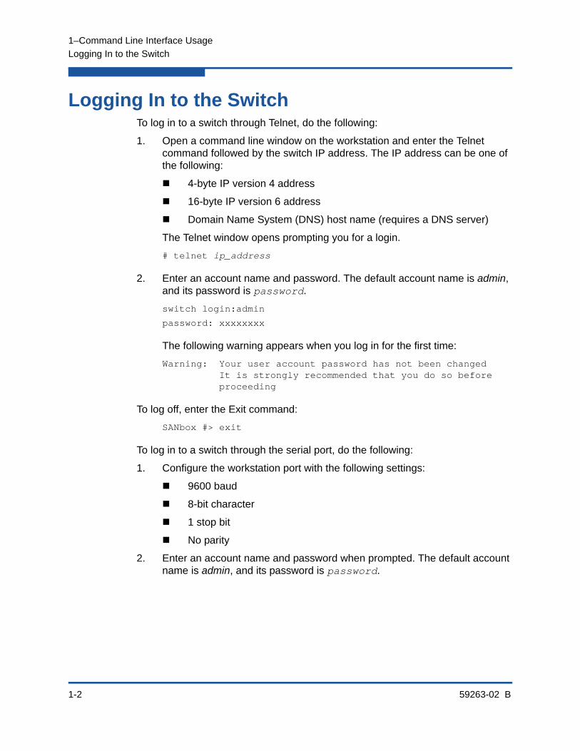
Logging In to the SwitchTo log in to a switch through Telnet, do the following:
1. Open a command line window on the workstation and enter the Telnet command followed by the switch IP address. The IP address can be one of the following:
4-byte IP version 4 address
16-byte IP version 6 address
Domain Name System (DNS) host name (requires a DNS server)
The Telnet window opens prompting you for a login.
# telnet ip_address
2. Enter an account name and password. The default account name is admin, and its password is password.
switch login:admin
password: xxxxxxxx
The following warning appears when you log in for the first time:
Warning: Your user account password has not been changed It is strongly recommended that you do so before proceeding
To log off, enter the Exit command:
SANbox #> exit
To log in to a switch through the serial port, do the following:
1. Configure the workstation port with the following settings:
9600 baud
8-bit character
1 stop bit
No parity
2. Enter an account name and password when prompted. The default account name is admin, and its password is password.

1–Command Line Interface Usage
Opening and Closing an Admin Session
59263-02 B 1-3
Opening and Closing an Admin SessionThe command line interface performs monitoring and configuration tasks. Commands that perform monitoring tasks are available to all user accounts. Commands that perform configuration tasks are available only after entering the Admin Start command to open an Admin session. A user account must have Admin authority to enter the Admin Start command.
The following is an example of how to open and close an Admin session:
SANbox #> admin start
SANbox (admin) #>
.
.
.
SANbox (admin) #> admin end
NOTE:
A switch supports a combined maximum of 19 logins or sessions, which are reserved as follows. Additional logins will be refused.
4 logins or sessions for internal applications such as management server and SNMP
9 high priority Telnet sessions
6 logins or sessions for Enterprise Fabric Suite™, QuickTools™, Application Programming Interface (API) , and Telnet.
1–Command Line Interface Usage
Entering Commands
1-4 59263-02 B
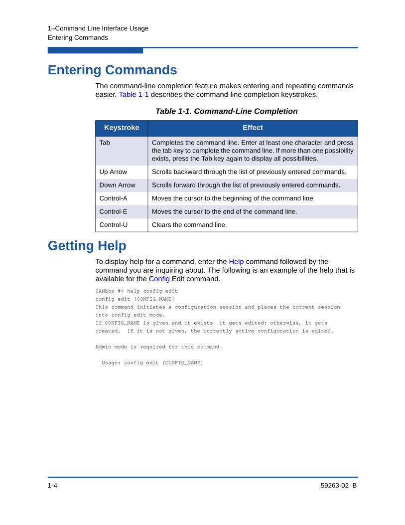
Entering CommandsThe command-line completion feature makes entering and repeating commands easier. Table 1-1 describes the command-line completion keystrokes.
Getting HelpTo display help for a command, enter the Help command followed by the command you are inquiring about. The following is an example of the help that is available for the Config Edit command.
SANbox #> help config edit
config edit [CONFIG_NAME]
This command initiates a configuration session and places the current session
into config edit mode.
If CONFIG_NAME is given and it exists, it gets edited; otherwise, it gets
created. If it is not given, the currently active configuration is edited.
Admin mode is required for this command.
Usage: config edit [CONFIG_NAME]
Table 1-1. Command-Line Completion
Keystroke Effect
Tab Completes the command line. Enter at least one character and press the tab key to complete the command line. If more than one possibility exists, press the Tab key again to display all possibilities.
Up Arrow Scrolls backward through the list of previously entered commands.
Down Arrow Scrolls forward through the list of previously entered commands.
Control-A Moves the cursor to the beginning of the command line
Control-E Moves the cursor to the end of the command line.
Control-U Clears the command line.

1–Command Line Interface Usage
Setting Page Breaks
59263-02 B 1-5
Setting Page BreaksSome display commands deliver so much information to the screen that it scrolls by too quickly to read it. You can limit the display to 20 lines by turning on page breaks. By default, page breaks are turned off.The following is an example of how to turn page breaks on and how it affects the display.
SANbox #> set pagebreak on
SANbox #> zone list
Zone ZoneSet
---- -------
Zone1
alpha
beta
Zone2
delta
echo
Zone3
sierra
tango
Zone4
gamma
delta
Press any key to continue, 'q' to quit ...

1–Command Line Interface Usage
Creating a Support File
1-6 59263-02 B
Creating a Support FileIf you contact technical support about a problem with your switch, they may request that you create and send a support file. This support file contains all of the switch configuration information, which can be helpful in diagnosing the problem. The Create Support command creates the support file (dump_support.tgz) on the switch. If your workstation has an FTP server, you can proceed with the command prompts to send the file from the switch to a remote host. Otherwise, you can use FTP to download the support file from the switch to your workstation.
The following example creates a support file and sends it to a remote host if your workstation has an FTP server.
SANbox #> create support
Log Msg:[Creating the support file - this will take several seconds]
FTP the dump support file to another machine? (y/n): y
Enter IPv4, IPv6 Address or hostname of remote computer: 10.20.33.130
Login name: johndoe
Enter remote directory name: bin/support
Would you like to continue downloading support file? (y/n) [n]: y
Connected to 10.20.33.130 (10.20.33.130).220 localhost.localdomain FTP server (Version wu-2.6.1-18) ready.331 Password required for johndoe.
Password: xxxxxxx
230 User johndoe logged in.cd bin/support250 CWD command successful.
lcd /itasca/conf/images
Local directory now /itasca/conf/images
bin
200 Type set to I.put dump_support.tgzlocal: dump_support.tgz remote: dump_support.tgz227 Entering Passive Mode (10,20,33,130,232,133)150 Opening BINARY mode data connection for dump_support.tgz.226 Transfer complete.43430 bytes sent in 0.292 secs (1.5e+02 Kbytes/sec)Remote system type is UNIX.Using binary mode to transfer files.221-You have transferred 43430 bytes in 1 files.221-Total traffic for this session was 43888 bytes in 1 transfers.221 Thank you for using the FTP service on localhost.localdomain.
NOTE:
Support files are deleted from the switch during a power cycle or switch reset.
1–Command Line Interface Usage
Creating a Support File
59263-02 B 1-7
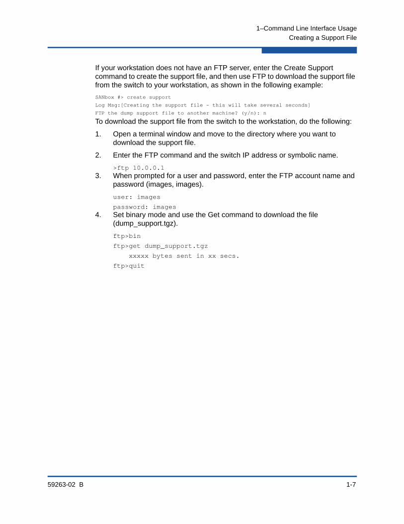
If your workstation does not have an FTP server, enter the Create Support command to create the support file, and then use FTP to download the support file from the switch to your workstation, as shown in the following example:
SANbox #> create support
Log Msg:[Creating the support file - this will take several seconds]
FTP the dump support file to another machine? (y/n): n
To download the support file from the switch to the workstation, do the following:
1. Open a terminal window and move to the directory where you want to download the support file.
2. Enter the FTP command and the switch IP address or symbolic name.
>ftp 10.0.0.13. When prompted for a user and password, enter the FTP account name and
password (images, images).
user: images
password: images4. Set binary mode and use the Get command to download the file
(dump_support.tgz).
ftp>bin
ftp>get dump_support.tgz
xxxxx bytes sent in xx secs.
ftp>quit

1–Command Line Interface Usage
Downloading and Uploading Files
1-8 59263-02 B
Downloading and Uploading FilesSeveral files that reside on the switch can be downloaded to the workstation for examination or for safekeeping. These files include the following:
Backup configuration file (configdata)
Log files (logfile)
Support files (dump_support.tgz)
You can upload firmware image files or backup configuration files to the switch to reinstall firmware or restore a corrupted configuration. The switch uses FTP to exchange files between the switch and the workstation.
To download a file from the switch to the workstation, do the following:
1. Enter the FTP command and the switch IP address or symbolic name.
>ftp 10.0.0.1
2. When prompted for a user and password, enter the FTP account name and password (images, images).
user: images
password: images
3. Set binary mode and use the Get command to download the file (configdata).
ftp>bin
ftp>get configdata
xxxxx bytes sent in xx secs.
ftp>quit
To upload a file from the workstation to the switch, do the following
1. Enter the FTP command and the switch IP address or symbolic name.
>ftp 10.0.0.1
2. When prompted for a user and password, enter the FTP account name and password (images, images).
user:images
password: images

1–Command Line Interface Usage
Downloading and Uploading Files
59263-02 B 1-9
3. Set binary mode and use the Put command to upload the file (config_switch_169).
ftp>put config_switch_169 configdata
xxxxx bytes sent in xx secs.
ftp>quit
For more information about reinstallation, backup and restore, and creating support and log files:
Refer to “Installing Firmware” on page 4-19 for information about installing firmware.
Refer to “Backing Up and Restoring a Switch Configuration” on page 4-13 for information about backing up and restoring a switch configuration.
Refer to “Creating and Downloading a Log File” on page 10-6 for information about creating a log file.
Refer to “Creating a Support File” on page 1-6 for information about creating a support file.

1–Command Line Interface Usage
Downloading and Uploading Files
1-10 59263-02 B

59263-02 B 2-1
2 User Account Configuration
User accounts and their respective passwords are the first line of switch security. A user account consists of an account name, an authority level, and an expiration date. Switches come from the factory with certain user accounts defined for special purposes. Table 2-1 describes these accounts, their passwords, and their purposes. These accounts cannot be deleted from the switch.
This section describes the following user account configuration tasks:
Displaying User Account Information
Creating User Accounts
Modifying User Accounts and Passwords
Table 2-1. Factory User Accounts
User Account
NamePassword Purpose
admin password Provides access to the Telnet server for managing the switch. Admin is the only account name that has per-mission to create and modify other user accounts. To secure your admin user account, be sure to change the password for this account.
images images Provides access to the File Transfer Protocol (FTP) server for exchanging files between the switch and the workstation.
prom prom Provides access to the Maintenance mode menu to perform switch recovery tasks. Refer to the QLogic 5800V Series Stackable Fibre Channel Switch Instal-lation Guide for information about using Maintenance mode.
2–User Account Configuration
Displaying User Account Information
2-2 59263-02 B
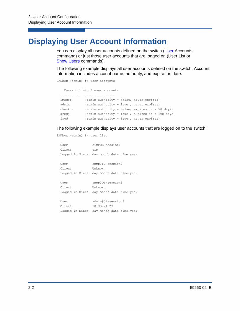
Displaying User Account InformationYou can display all user accounts defined on the switch (User Accounts command) or just those user accounts that are logged on (User List or Show Users commands).
The following example displays all user accounts defined on the switch. Account information includes account name, authority, and expiration date.
SANbox (admin) #> user accounts
Current list of user accounts
-----------------------------
images (admin authority = False, never expires)
admin (admin authority = True , never expires)
chuckca (admin authority = False, expires in < 50 days)
gregj (admin authority = True , expires in < 100 days)
fred (admin authority = True , never expires)
The following example displays user accounts that are logged on to the switch:
SANbox (admin) #> user list
User cim@OB-session1
Client cim
Logged in Since day month date time year
User snmp@IB-session2
Client Unknown
Logged in Since day month date time year
User snmp@OB-session3
Client Unknown
Logged in Since day month date time year
User admin@OB-session8
Client 10.33.21.27
Logged in Since day month date time year

2–User Account Configuration
Creating User Accounts
59263-02 B 2-3
Creating User AccountsA user account consists of an account name, an authority level, and an expiration date. The account name can be up to 15 characters: the first character must be alphanumeric; the remaining characters must be ASCII characters except semicolon (;), comma (,), #, and period (.). The authority level grants admin authority (true) or denies it (false). The expiration date sets the date when the user account expires. Only the Admin user account can create user accounts. You add user accounts with the User Add command.
The following example creates a new user account named user1 with admin authority that expires in 100 days.
SANbox (admin) #> user add
Press 'q' and the ENTER key to abort this command.
account name (1-15 chars) : user1
account password (8-20 chars) : *******
please confirm account password: *******
set account expiration in days (0-2000, 0=never): [0] 100
should this account have admin authority? (y/n): [n] y
OK to add user account 'user1' with admin authority
and to expire in 100 days?
Please confirm (y/n): [n] y
2–User Account Configuration
Modifying User Accounts and Passwords
2-4 59263-02 B
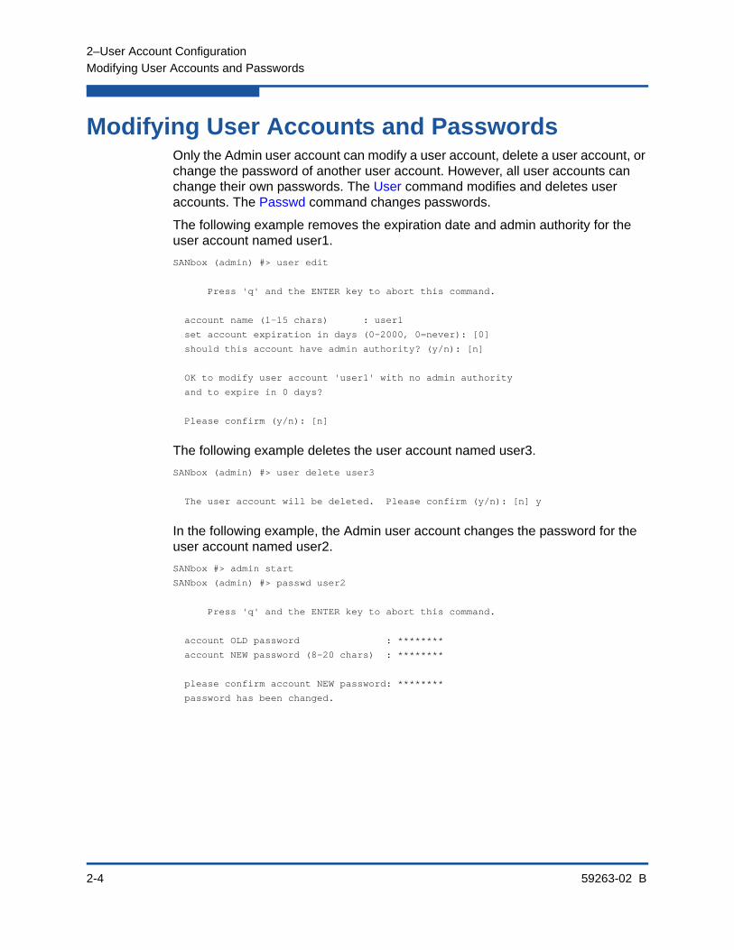
Modifying User Accounts and PasswordsOnly the Admin user account can modify a user account, delete a user account, or change the password of another user account. However, all user accounts can change their own passwords. The User command modifies and deletes user accounts. The Passwd command changes passwords.
The following example removes the expiration date and admin authority for the user account named user1.
SANbox (admin) #> user edit
Press 'q' and the ENTER key to abort this command.
account name (1-15 chars) : user1
set account expiration in days (0-2000, 0=never): [0]
should this account have admin authority? (y/n): [n]
OK to modify user account 'user1' with no admin authority
and to expire in 0 days?
Please confirm (y/n): [n]
The following example deletes the user account named user3.
SANbox (admin) #> user delete user3
The user account will be deleted. Please confirm (y/n): [n] y
In the following example, the Admin user account changes the password for the user account named user2.
SANbox #> admin start
SANbox (admin) #> passwd user2
Press 'q' and the ENTER key to abort this command.
account OLD password : ********
account NEW password (8-20 chars) : ********
please confirm account NEW password: ********
password has been changed.

59263-02 B 3-1
3 Network Configuration
Network configuration consists of the IP parameters that identify the switch in the network and provide for IP security. This section describes the following network configuration tasks:
Displaying the Network Configuration
Configuring the Ethernet Port
Verifying a Switch in the Network
Managing IP Security
Displaying the Network ConfigurationThe Show Fabric command displays IP addresses for all switches in the fabric as shown in the following example.
SANbox #> show fabric
Domain *133(0x85)
WWN 10:00:00:c0:dd:0d:53:91
SymbolicName SANbox
HostName <undefined>
EthIPv4Address 10.20.116.133
EthIPv6Address <undefined>
* indicates principal switch

3–Network Configuration
Configuring the Ethernet Port
3-2 59263-02 B
The Show Setup System command displays the entire switch network configuration, which includes the following:
IP configurations (versions 4 and 6)
DNS server configuration
To display specific information, add the corresponding keyword. For example, to display IP version 6 configuration information, enter the Show Setup System Ipv6 command:
SANbox #> show setup system ipv6
System Information
------------------
EthIPv6NetworkEnable False
EthIPv6NetworkDiscovery Static
EthIPv6NetworkAddress 2001::1/64
EthIPv6GatewayAddress fe80::1
Configuring the Ethernet PortUse the Set Setup System command in an Admin session to configure the Ethernet port and other network parameters. You can configure all of the following parameters in one session, or you can configure specific parameters by adding the corresponding keyword:
IP Version 4 Configuration
IP Version 6 Configuration
DNS Server Configuration
IP Version 4 ConfigurationThe switch supports IP version 4, which includes the following:
Network discovery method
IP address
Subnet mask
IP gateway address

3–Network Configuration
Configuring the Ethernet Port
59263-02 B 3-3
The network discovery method determines how the switch acquires its IP address. The IP address can come from the IP address that resides on the switch or from a server. The switch supports network discovery from the following server types:
Bootstrap Protocol (BootP)
Reverse Address Resolution Protocol (RARP)
Dynamic Host Configuration Protocol (DHCP)
To configure the IP version 4 parameters, enter the Set Setup System Ipv4 command:
SANbox (admin) #> set setup system ipv4
A list of attributes with formatting and current values will follow.
Enter a new value or simply press the ENTER key to accept the current value.
If you wish to terminate this process before reaching the end of the list
press 'q' or 'Q' and the ENTER key to do so.
Current Values:
EthIPv4NetworkEnable True
EthIPv4NetworkDiscovery Static
EthIPv4NetworkAddress 10.20.116.133
EthIPv4NetworkMask 255.255.255.0
EthIPv4GatewayAddress 10.20.116.1
New Value (press ENTER to accept current value, 'q' to quit, 'n' for none):
EthIPv4NetworkEnable (True / False) :
EthIPv4NetworkDiscovery (1=Static, 2=Bootp, 3=Dhcp, 4=Rarp) :
EthIPv4NetworkAddress (dot-notated IP Address) : 10:20:30:40
EthIPv4NetworkMask (dot-notated IP Address) : 255.0.0.0
EthIPv4GatewayAddress (dot-notated IPv4 Address) : 10.20.30.254
Do you want to save and activate this system setup? (y/n): [n] y

3–Network Configuration
Configuring the Ethernet Port
3-4 59263-02 B
IP Version 6 ConfigurationThe switch supports IP version 6, which includes the following:
Network discovery method
IP address
IP gateway address
The network discovery method determines how the switch acquires its IP address. The IP address can come from the IP address (static) that resides on the switch, from a DHCP server, or it can be learned from a router through the Neighbor Discovery Protocol (NDP). To configure the IP version 6 parameters, enter the Set Setup System Ipv6 command:
SANbox (admin) #> set setup system ipv6
A list of attributes with formatting and current values will follow.
Enter a new value or simply press the ENTER key to accept the current value.
If you wish to terminate this process before reaching the end of the list
press 'q' or 'Q' and the ENTER key to do so.
Current Values:
EthIPv6NetworkEnable False
EthIPv6Discovery Static
EthIPv6NetworkAddress <undefined>
EthIPv6GatewayAddress <undefined>
New Value (press ENTER to accept current value, 'q' to quit, 'n' for none):
EthIPv6NetworkEnable (True / False) :
EthIPv6Discovery (1=Static, 2=Dhcpv6, 3=Ndp) :
EthIPv6NetworkAddress (IPv6 Address/Mask Length format) :
EthIPv6GatewayAddress (IPv6 Address) :
Do you want to save and activate this system setup? (y/n): [n]
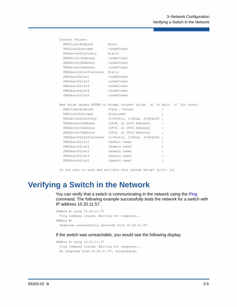
DNS Server ConfigurationA DNS server manages the host names for a fabric. This enables you to specify servers and switches by a meaningful name rather than IP address. To configure a DNS server, enter the Set Setup System Dns command in an Admin session as shown in the following example:
SANbox (admin) #> set setup system dns
A list of attributes with formatting and current values will follow.
Enter a new value or simply press the ENTER key to accept the current value.
If you wish to terminate this process before reaching the end of the list
press 'q' or 'Q' and the ENTER key to do so.
3–Network Configuration
Verifying a Switch in the Network
59263-02 B 3-5
Current Values:
DNSClientEnabled False
DNSLocalHostname <undefined>
DNSServerDiscovery Static
DNSServer1Address <undefined>
DNSServer2Address <undefined>
DNSServer3Address <undefined>
DNSSearchListDiscovery Static
DNSSearchList1 <undefined>
DNSSearchList2 <undefined>
DNSSearchList3 <undefined>
DNSSearchList4 <undefined>
DNSSearchList5 <undefined>
New Value (press ENTER to accept current value, 'q' to quit, 'n' for none):
DNSClientEnabled (True / False) :
DNSLocalHostname (hostname) :
DNSServerDiscovery (1=Static, 2=Dhcp, 3=Dhcpv6) :
DNSServer1Address (IPv4, or IPv6 Address) :
DNSServer2Address (IPv4, or IPv6 Address) :
DNSServer3Address (IPv4, or IPv6 Address) :
DNSSearchListDiscovery (1=Static, 2=Dhcp, 3=Dhcpv6) :
DNSSearchList1 (domain name) :
DNSSearchList2 (domain name) :
DNSSearchList3 (domain name) :
DNSSearchList4 (domain name) :
DNSSearchList5 (domain name) :
Do you want to save and activate this system setup? (y/n): [n]
Verifying a Switch in the NetworkYou can verify that a switch is communicating in the network using the Ping command. The following example successfully tests the network for a switch with IP address 10.20.11.57.
SANbox #> ping 10.20.11.57
Ping command issued. Waiting for response...
SANbox #>
Response successfully received from 10.20.11.57.
If the switch was unreachable, you would see the following display.
SANbox #> ping 10.20.11.57
Ping command issued. Waiting for response...
No response from 10.20.11.57. Unreachable.
3–Network Configuration
Managing IP Security
3-6 59263-02 B
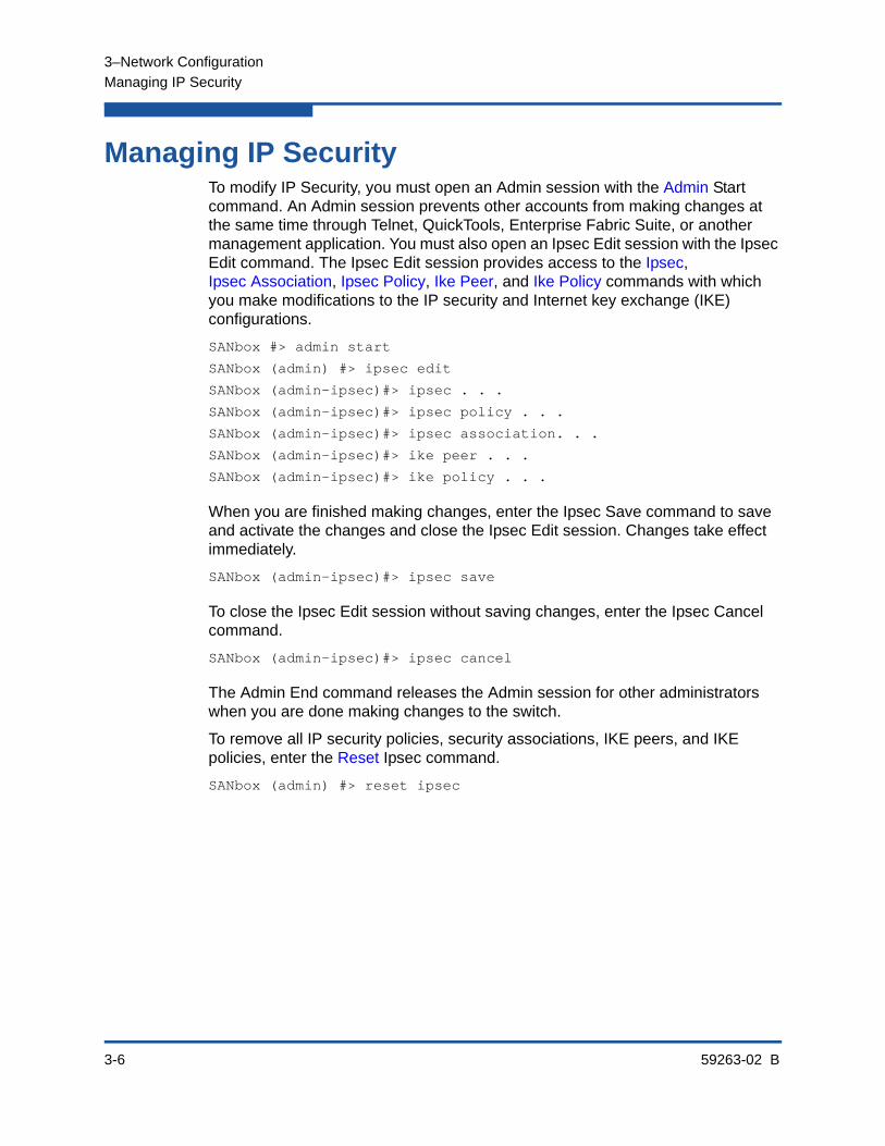
Managing IP SecurityTo modify IP Security, you must open an Admin session with the Admin Start command. An Admin session prevents other accounts from making changes at the same time through Telnet, QuickTools, Enterprise Fabric Suite, or another management application. You must also open an Ipsec Edit session with the Ipsec Edit command. The Ipsec Edit session provides access to the Ipsec, Ipsec Association, Ipsec Policy, Ike Peer, and Ike Policy commands with which you make modifications to the IP security and Internet key exchange (IKE) configurations.
SANbox #> admin start
SANbox (admin) #> ipsec edit
SANbox (admin-ipsec)#> ipsec . . .
SANbox (admin-ipsec)#> ipsec policy . . .
SANbox (admin-ipsec)#> ipsec association. . .
SANbox (admin-ipsec)#> ike peer . . .
SANbox (admin-ipsec)#> ike policy . . .
When you are finished making changes, enter the Ipsec Save command to save and activate the changes and close the Ipsec Edit session. Changes take effect immediately.
SANbox (admin-ipsec)#> ipsec save
To close the Ipsec Edit session without saving changes, enter the Ipsec Cancel command.
SANbox (admin-ipsec)#> ipsec cancel
The Admin End command releases the Admin session for other administrators when you are done making changes to the switch.
To remove all IP security policies, security associations, IKE peers, and IKE policies, enter the Reset Ipsec command.
SANbox (admin) #> reset ipsec

3–Network Configuration
Managing IP Security
59263-02 B 3-7
The following subsections present IP security concepts and management tasks:
IP Security Concepts
Displaying IP Security Information
Managing the Security Policy Database
Managing the Security Association Database
Managing IKE Peers
Managing IKE Policies
Resetting the IP Security Configuration
IP Security ConceptsIP security provides encryption-based security for IPv4 and IP6 communications between devices through the use of security policies and associations. The Internet key exchange (IKE) protocol automates the creation of IP security associations on the switch and connected devices and the sharing of encryption keys through the configuration of IKE peers and policies. The security association database comprises all IP security associations. The security policy database comprises all IP security policies. The IKE database comprises all IKE policies and peers.
Security Policies and AssociationsA security policy defines the following parameters:
Connection source and destination
Data traffic direction: inbound or outbound
Protocols for which to protect data traffic
Security protocols; authentication header (AH) or encapsulating security payload (ESP)
Level of protection: IP security, discard, or none
NOTE:
IP security configurations can be complex: it is possible to unintentionally isolate a switch from all communication. If this happens, you can disable IP security by placing the switch in maintenance mode, and correct the problem through the serial port interface. For information about using maintenance mode and connecting through the serial port, see the QLogic 5800V Series Stackable Fibre Channel Switch Installation Guide.

3–Network Configuration
Managing IP Security
3-8 59263-02 B
Policies can define security for host-to-host and host-to-gateway connections; one policy for each direction. For example, to secure the connection between two hosts, you need two policies: one for outbound traffic from the source to the destination, and another for inbound traffic to the source from the destination. You can specify sources and destinations by IP addresses (version 4 or 6) or DNS host names. If a host name resolves to more than one IP address, the switch creates the necessary policies and associations. You can recognize these dynamic policies and associations because their names begin with DynamicSP_ and DynamicSA_ respectively.
A security association defines the encryption algorithm and encryption key (public key or secret) to apply when called by a security policy. A security policy may call several associations at different times, but each association is related to only one policy. The security association database is the set of all security associations.
You can apply IP security to all communication between two systems, or to selected protocols, such as ICMP, TCP, or UDP. Furthermore, instead of applying IP security, you can choose to discard all inbound or outbound traffic, or allow all traffic without encryption. Both the AH and ESP security protocols provide source authentication, ensure data integrity, and protect against replay.
IKE Peers and PoliciesIKE is a protocol that automates the configuration of matching IP security associations on the switch and on the connected device (or peer). The IKE peer defines the IKE security association connection through which the IKE policy configures the IP security associations.The IKE policy defines the type of data traffic to secure between the switch and the peer, and how to encrypt that data. You must create the same IKE peer and IKE policy configurations on the switch and the peer device.
Public Key InfrastructurePublic key encryption requires a public key, a corresponding private key, and the necessary certificates to authenticate them. Public key infrastructure (PKI) provides support for the creation and management of public/private key pairs, signed certificates, and certificate authority (CA) certificates when using IKE. You can create a public/private key and combine it with one or more device identities to generate a certificate request. Submit the certificate request to a CA to obtain a signed certificate, which contains the authenticated public/private key pair. In addition to the signed certificate, you must also obtain a CA certificate to authenticate the CA. After downloading the signed certificate and a CA certificate to the switch and importing them into the PKI database, the signed certificate (which contains the authenticated public key) can then be used to complete the IKE peer configuration.

3–Network Configuration
Managing IP Security
59263-02 B 3-9
Displaying IP Security InformationYou can display the following types of IP security information:
IP Security Policy and Association Information
Public Key Infrastructure Information
IKE Peer and Policy Information
IP Security Configuration History
IP Security Configuration Limits
IP Security Policy and Association InformationTo display general or specific security policy and association information, enter the Ipsec List command. The Ipsec List command does not require an Admin session nor an Ipsec Edit session. Within an Ipsec Edit session, the Ipsec Association List and Ipsec Policy List commands display the same information. You can display active, configured, and edited polices and associations:
Active—policies and associations currently in use
Configured—policies and associations that have been saved in the IP security database
Edited—policies and associations that are being edited, but have not yet been saved
The following example displays all active security policies and associations:
SANbox #> ipsec list
Active IPsec Information
Security Association Database
-----------------------------
h2h-sh-sa
h2h-hs-sa
Security Policy Database
------------------------
h2h-hs-sp
h2h-sh-sp
Summary
-------
Security Association Count: 2
Security Policy Count: 2

3–Network Configuration
Managing IP Security
3-10 59263-02 B
IKE Peer and Policy InformationTo display general or specific peer and policy information, enter the Ike List command. The Ike List command does not require an Admin session nor an Ipsec Edit session. The Ike Peer List and Ike Policy List commands display the same information. You can display active, configured, and edited peers and polices:
Active—peers and policies currently in use
Configured—peers and policies that have been saved in the IKE database
Edited—peers and policies that are being edited, but have not yet been saved
The following example displays all configured IKE peers and policies:
SANbox #> ike list configured
Configured (saved) IKE Information
Peer Policy
------ ----
peer_1
policy_1
policy_2
peer_2
policy_3
peer_3
(no policies)
(No peer)
policy_4
Summary:
Peer Count 3
Policy Count 4
Public Key Infrastructure InformationTo display information in the PKI database about public/private key pairs, signed certificates, and certificate authorities, enter the following commands:
Key List
Certificate List Local
Cert_Authority List
The following is an example of the Key List command for key512:
SANbox #> key list key512
Key key512:
private key with:
pubkey: RSA 512 bits
keyid: 49:80:4c:aa:d3:c3:bc:c7:f5:b1:41:34:ce:71:48:1d:b9:b3:d9:f9
subjkey: f4:b6:b9:27:25:7a:5a:69:a0:9e:cf:14:cd:3c:88:e9:d5:b1:aa:4a
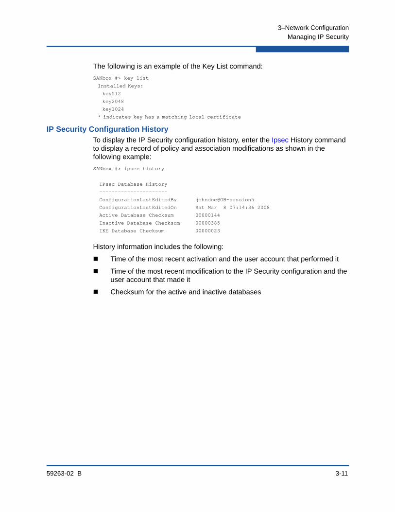
3–Network Configuration
Managing IP Security
59263-02 B 3-11
The following is an example of the Key List command:
SANbox #> key list
Installed Keys:
key512
key2048
key1024
* indicates key has a matching local certificate
IP Security Configuration HistoryTo display the IP Security configuration history, enter the Ipsec History command to display a record of policy and association modifications as shown in the following example:
SANbox #> ipsec history
IPsec Database History
----------------------
ConfigurationLastEditedBy johndoe@OB-session5
ConfigurationLastEditedOn Sat Mar 8 07:14:36 2008
Active Database Checksum 00000144
Inactive Database Checksum 00000385
IKE Database Checksum 00000023
History information includes the following:
Time of the most recent activation and the user account that performed it
Time of the most recent modification to the IP Security configuration and the user account that made it
Checksum for the active and inactive databases

3–Network Configuration
Managing IP Security
3-12 59263-02 B
IP Security Configuration LimitsTo display a summary of the objects in the IP Security configuration and their maximum limit, enter the Ipsec Limits command to as shown in the following example:
SANbox #> ipsec limits
Configured (saved) IPsec Information
IPsec Attribute Maximum Current
--------------- ------- -------
MaxConfiguredSAs 512 0
MaxConfiguredSPs 128 0
MaxConfiguredIKEPeers 16 0
MaxConfiguredIKEPolicies 256 0
In an Ipsec Edit session, Ipsec Limits command displays the number of both configured associations and policies, plus those created in the edit session but not yet saved.
Managing the Security Policy DatabaseThe security policy database is made up of user-defined policies and dynamic policies (policies created by the switch). In addition to creating a policy, you can delete, modify, rename, and copy user-defined policies. Dynamic policies can only be copied.
Creating a Policy
Deleting a Policy
Modifying a User-Defined Policy
Renaming a User-Defined Policy
Copying a Policy
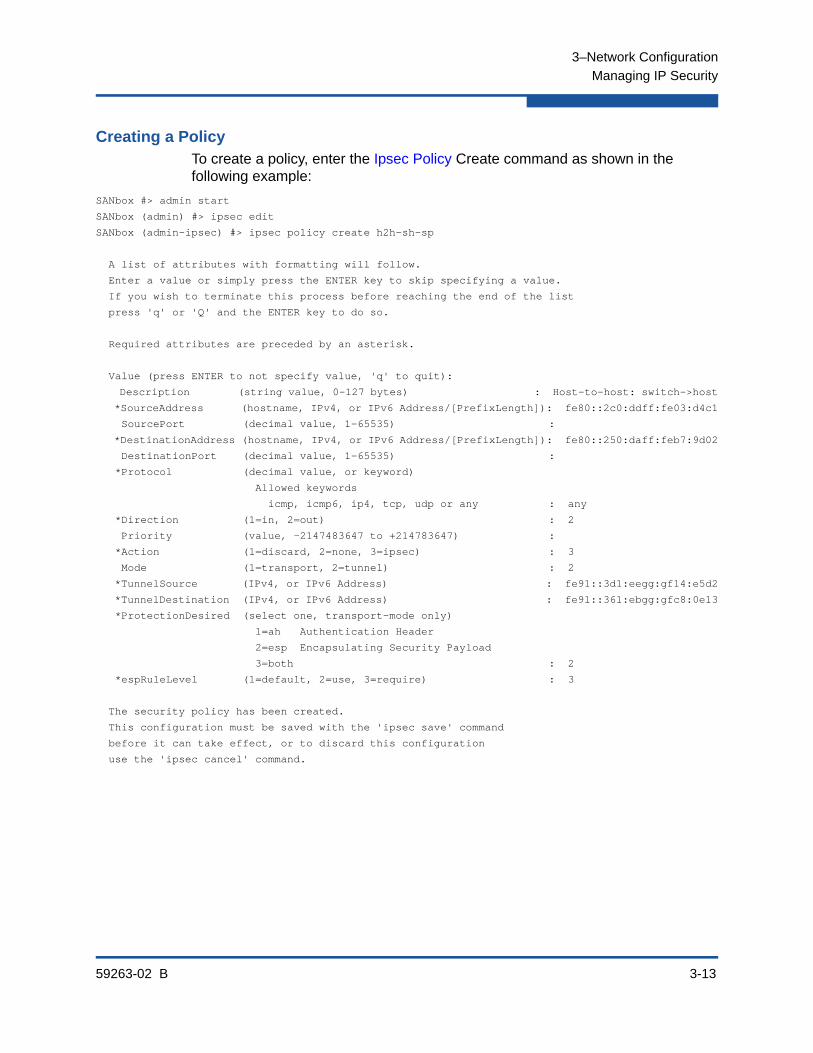
3–Network Configuration
Managing IP Security
59263-02 B 3-13
Creating a PolicyTo create a policy, enter the Ipsec Policy Create command as shown in the following example:
SANbox #> admin start
SANbox (admin) #> ipsec edit
SANbox (admin-ipsec) #> ipsec policy create h2h-sh-sp
A list of attributes with formatting will follow.
Enter a value or simply press the ENTER key to skip specifying a value.
If you wish to terminate this process before reaching the end of the list
press 'q' or 'Q' and the ENTER key to do so.
Required attributes are preceded by an asterisk.
Value (press ENTER to not specify value, 'q' to quit):
Description (string value, 0-127 bytes) : Host-to-host: switch->host
*SourceAddress (hostname, IPv4, or IPv6 Address/[PrefixLength]): fe80::2c0:ddff:fe03:d4c1
SourcePort (decimal value, 1-65535) :
*DestinationAddress (hostname, IPv4, or IPv6 Address/[PrefixLength]): fe80::250:daff:feb7:9d02
DestinationPort (decimal value, 1-65535) :
*Protocol (decimal value, or keyword)
Allowed keywords
icmp, icmp6, ip4, tcp, udp or any : any
*Direction (1=in, 2=out) : 2
Priority (value, -2147483647 to +214783647) :
*Action (1=discard, 2=none, 3=ipsec) : 3
Mode (1=transport, 2=tunnel) : 2
*TunnelSource (IPv4, or IPv6 Address) : fe91::3d1:eegg:gf14:e5d2
*TunnelDestination (IPv4, or IPv6 Address) : fe91::361:ebgg:gfc8:0e13
*ProtectionDesired (select one, transport-mode only)
1=ah Authentication Header
2=esp Encapsulating Security Payload
3=both : 2
*espRuleLevel (1=default, 2=use, 3=require) : 3
The security policy has been created.
This configuration must be saved with the 'ipsec save' command
before it can take effect, or to discard this configuration
use the 'ipsec cancel' command.
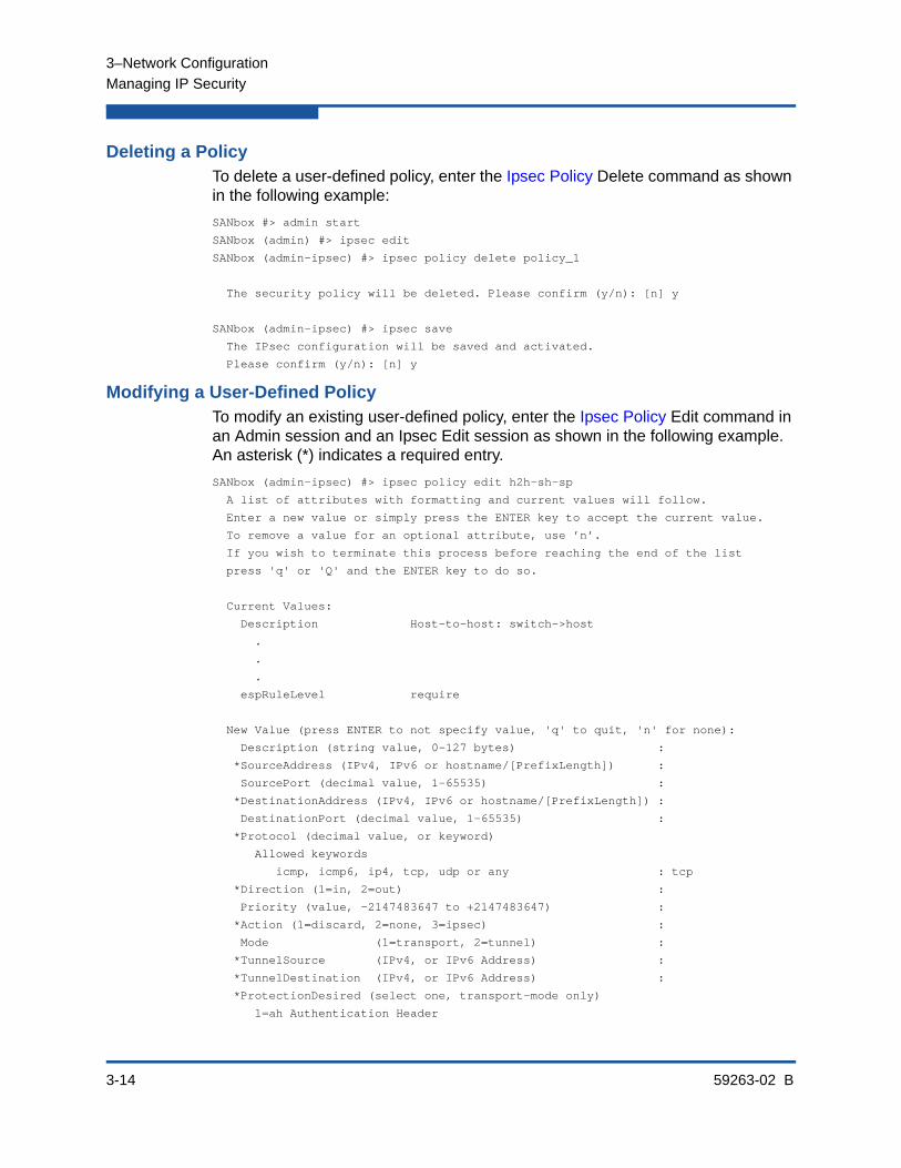
3–Network Configuration
Managing IP Security
3-14 59263-02 B
Deleting a PolicyTo delete a user-defined policy, enter the Ipsec Policy Delete command as shown in the following example:
SANbox #> admin start
SANbox (admin) #> ipsec edit
SANbox (admin-ipsec) #> ipsec policy delete policy_1
The security policy will be deleted. Please confirm (y/n): [n] y
SANbox (admin-ipsec) #> ipsec save
The IPsec configuration will be saved and activated.
Please confirm (y/n): [n] y
Modifying a User-Defined PolicyTo modify an existing user-defined policy, enter the Ipsec Policy Edit command in an Admin session and an Ipsec Edit session as shown in the following example. An asterisk (*) indicates a required entry.
SANbox (admin-ipsec) #> ipsec policy edit h2h-sh-sp
A list of attributes with formatting and current values will follow.
Enter a new value or simply press the ENTER key to accept the current value.
To remove a value for an optional attribute, use ’n’.
If you wish to terminate this process before reaching the end of the list
press 'q' or 'Q' and the ENTER key to do so.
Current Values:
Description Host-to-host: switch->host
.
.
.
espRuleLevel require
New Value (press ENTER to not specify value, 'q' to quit, 'n' for none):
Description (string value, 0-127 bytes) :
*SourceAddress (IPv4, IPv6 or hostname/[PrefixLength]) :
SourcePort (decimal value, 1-65535) :
*DestinationAddress (IPv4, IPv6 or hostname/[PrefixLength]) :
DestinationPort (decimal value, 1-65535) :
*Protocol (decimal value, or keyword)
Allowed keywords
icmp, icmp6, ip4, tcp, udp or any : tcp
*Direction (1=in, 2=out) :
Priority (value, -2147483647 to +2147483647) :
*Action (1=discard, 2=none, 3=ipsec) :
Mode (1=transport, 2=tunnel) :
*TunnelSource (IPv4, or IPv6 Address) :
*TunnelDestination (IPv4, or IPv6 Address) :
*ProtectionDesired (select one, transport-mode only)
1=ah Authentication Header
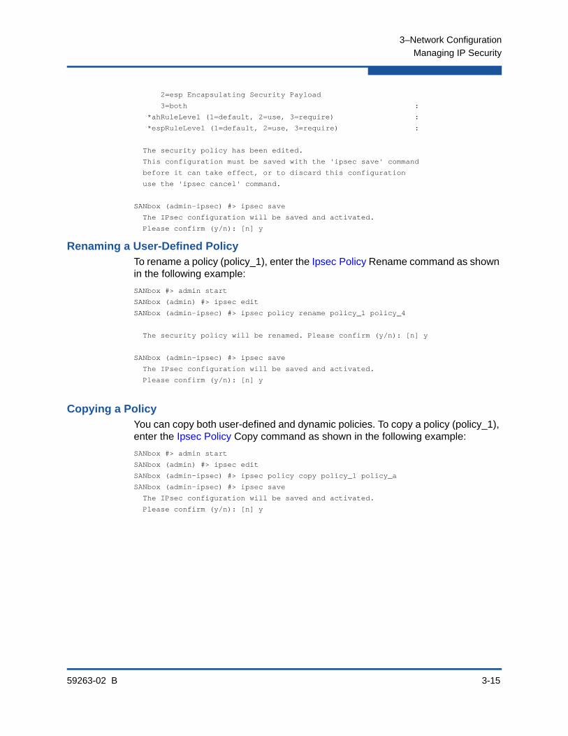
3–Network Configuration
Managing IP Security
59263-02 B 3-15
2=esp Encapsulating Security Payload
3=both :
*ahRuleLevel (1=default, 2=use, 3=require) :
*espRuleLevel (1=default, 2=use, 3=require) :
The security policy has been edited.
This configuration must be saved with the 'ipsec save' command
before it can take effect, or to discard this configuration
use the 'ipsec cancel' command.
SANbox (admin-ipsec) #> ipsec save
The IPsec configuration will be saved and activated.
Please confirm (y/n): [n] y
Renaming a User-Defined PolicyTo rename a policy (policy_1), enter the Ipsec Policy Rename command as shown in the following example:
SANbox #> admin start
SANbox (admin) #> ipsec edit
SANbox (admin-ipsec) #> ipsec policy rename policy_1 policy_4
The security policy will be renamed. Please confirm (y/n): [n] y
SANbox (admin-ipsec) #> ipsec save
The IPsec configuration will be saved and activated.
Please confirm (y/n): [n] y
Copying a PolicyYou can copy both user-defined and dynamic policies. To copy a policy (policy_1), enter the Ipsec Policy Copy command as shown in the following example:
SANbox #> admin start
SANbox (admin) #> ipsec edit
SANbox (admin-ipsec) #> ipsec policy copy policy_1 policy_a
SANbox (admin-ipsec) #> ipsec save
The IPsec configuration will be saved and activated.
Please confirm (y/n): [n] y
3–Network Configuration
Managing IP Security
3-16 59263-02 B
Managing the Security Association DatabaseThe security association database is made up of user-defined associations and dynamic associations (associations created by the switch). In addition to creating an association, you can delete, modify, rename, and copy user-defined associations. Dynamic associations can only be copied.
Creating an Association
Deleting an Association
Modifying a User-Defined Association
Renaming a User-Defined Association
Copying an Association

3–Network Configuration
Managing IP Security
59263-02 B 3-17
Creating an AssociationTo create an association, enter the Ipsec Association Create command as shown in the following example:
SANbox #> admin start
SANbox (admin) #> ipsec edit
SANbox (admin-ipsec) #> ipsec association create h2h-sh-sa
A list of attributes with formatting will follow.
Enter a value or simply press the ENTER key to skip specifying a value.
If you wish to terminate this process before reaching the end of the list
press 'q' or 'Q' and the ENTER key to do so.
Required attributes are preceded by an asterisk.
Value (press ENTER to not specify value, 'q' to quit):
Description (string value, 0-127 bytes) : Host-to-host: switch->host
*SourceAddress (hostname, IPv4, or IPv6 Address) : fe80::2c0:ddff:fe03:d4c1
*DestinationAddress (hostname, IPv4, or IPv6 Address) : fe80::250:daff:feb7:9d02
*Protocol (1=esp, 2=esp-old, 3=ah, 4=ah-old) : 1
*SPI (decimal value, 256-4294967295) : 333
Authentication (select an authentication algorithm)
1=hmac-md5 (16 byte key)
2=hmac-sha1 (20 byte key)
3=hmac-sha256 (32 byte key)
4=aes-xcbc-mac (16 byte key)
authentication algorithm choice : 2
*AuthenticationKey (quoted string or raw hex bytes) : "12345678901234567890"
*Encryption (select an encryption algorithm)
1=des-cbc (8 byte key)
2=3des-cbc (24 byte key)
3=null (0 byte key)
4=blowfish-cbc (5-56 byte key)
5=aes-cbc (16/24/32 byte key)
6=twofish-cbc (16-32 byte key)
encryption algorithm choice : 2
*EncryptionKey (quoted string or raw hex bytes) : "123456789012345678901234"
Mode (1=transport, 2=tunnel) : 1
The security association has been created.
This configuration must be saved with the 'ipsec save' command
before it can take effect, or to discard this configuration
use the 'ipsec cancel' command.
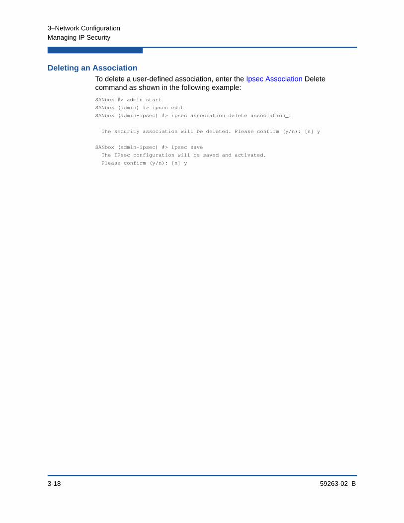
3–Network Configuration
Managing IP Security
3-18 59263-02 B
Deleting an AssociationTo delete a user-defined association, enter the Ipsec Association Delete command as shown in the following example:
SANbox #> admin start
SANbox (admin) #> ipsec edit
SANbox (admin-ipsec) #> ipsec association delete association_1
The security association will be deleted. Please confirm (y/n): [n] y
SANbox (admin-ipsec) #> ipsec save
The IPsec configuration will be saved and activated.
Please confirm (y/n): [n] y

3–Network Configuration
Managing IP Security
59263-02 B 3-19
Modifying a User-Defined AssociationTo modify an existing user-defined association, enter the Ipsec Association Edit command in an Admin session and an Ipsec Edit session as shown in the following example. An asterisk (*) indicates a required entry.
SANbox (admin-ipsec) #> ipsec association edit h2h-sh-sa
A list of attributes with formatting and current values will follow. Enter a new value or simply press the ENTER key to accept the current value. To remove a value for an optional attribute, use ’n’. If you wish to terminate this process before reaching the end of the list press 'q' or 'Q' and the ENTER key to do so.
Current Values:
Description Host-to-host: switch->host
.
.
EncryptionKey 123456789012345678901234
New Value (press ENTER to not specify value, 'q' to quit, 'n' for none):
Description (string value, 0-127 bytes) :
*SourceAddress (IPv4, IPv6 or hostname) :
*DestinationAddress (IPv4, IPv6 or hostname) :
*Protocol (1=esp, 2=esp-old, 3=ah, 4=ah-old) : ah
*SPI (decimal value, 256-4294967295) :
Authentication (select an authentication algorithm)
1=hmac-md5 (16 byte key)
2=hmac-sha1 (20 byte key)
3=hmac-sha256 (32 byte key)
4=aes-xcbc-mac (16 byte key)
authentication algorithm choice :
*AuthenticationKey (quotes string or raw hex bytes) :
*Encryption (select an encryption algorithm)
1=des-cbc (8 byte key)
2=3des-cbc (24 byte key)
3=null (0 byte key)
4=blowfish-cbc (5-56 byte key)
5=aes-cbc (16/24/32 byte key)
6=twofish-cbc (32 byte key)
encryption algorithm choice :
*EncryptionKey (quoted string or raw hex bytes) :
Mode (1=transport, 2=tunnel) :
The security association has been edited.
This configuration must be saved with the 'ipsec save' command
before it can take effect, or to discard this configuration
use the 'ipsec cancel' command.
SANbox (admin-ipsec) #> ipsec save
The IPsec configuration will be saved and activated.
Please confirm (y/n): [n] y

3–Network Configuration
Managing IP Security
3-20 59263-02 B
Renaming a User-Defined AssociationTo rename a user-defined association (associaton_1), enter the Ipsec Association Rename command as shown in the following example:
SANbox #> admin start
SANbox (admin) #> ipsec edit
SANbox (admin-ipsec) #> ipsec association rename association_1 association_4
The security association will be renamed. Please confirm (y/n): [n] y
SANbox (admin-ipsec) #> ipsec save
The IPsec configuration will be saved and activated.
Please confirm (y/n): [n] y
Copying an AssociationYou can copy both user-defined and dynamic associations. To copy an association (association_1), enter the Ipsec Association Copy command as shown in the following example:
SANbox #> admin start
SANbox (admin) #> ipsec edit
SANbox (admin-ipsec) #> ipsec association copy association_1 association_a
SANbox (admin-ipsec) #> ipsec save
The IPsec configuration will be saved and activated.
Please confirm (y/n): [n] y
Managing IKE PeersAn IKE peer defines a peer device and configures the IKE security association through which the switch establishes the IP security associations defined by an IKE policy. The IKE database is made up of IKE peers and policies. In addition to creating an IKE peer, you can delete, modify, rename, and copy user-defined peers.
Creating an IKE PeerTo create an IKE peer, enter the Ike Peer Create command as shown in the following example:
SANbox ># admin start
SANbox (admin) #> ipsec edit
SANbox (admin-ipsec) #> ike peer create peer_1
A list of attributes with formatting will follow.
Enter a value or simply press the ENTER key to skip specifying a value.
If you wish to terminate this process before reaching the end of the list
press 'q' or 'Q' and the ENTER key to do so.
Required attributes are preceded by an asterisk.
Value (press ENTER to not specify value, 'q' to quit):

3–Network Configuration
Managing IP Security
59263-02 B 3-21
Description (string, max=127 chars, N=None) : Peer 1
*Address (hostname, IPv4, or IPv6 Address) : 10.0.0.3
Lifetime (decimal value, 900-86400 seconds) : 3600
*Encryption (select one or more encryption algorithms)
1=3des_cbc
2=aes_cbc_128
3=aes_cbc_192
4=aes_cbc_256 : 1 4
*Integrity (select one or more integrity algorithms)
1=md5_96
2=sha1_96
3=sha2_256
4=aes_xcbc_96 : 1 2 3
*DHGroup (select one or more Diffie-Hellman Groups)
1, 2, 5, 14, 24 : 2 14
Restrict (True / False) : True
*Authentication (1=secret, 2=public_key) : 1
*Key (quoted string or raw hex bytes)
maximum length for quoted string = 128
maximum length for raw hex bytes = 256
the raw hex length must be even : 0x11223344
The IKE peer has been created.
This configuration must be saved with the 'ipsec save' command
before it can take effect, or to discard this configuration
use the 'ipsec cancel' command.
SANbox (admin-IPSEC) #> ipsec save
Deleting an IKE PeerTo delete an IKE peer, enter the Ike Peer Delete command as shown in the following example:
SANbox #> admin start
SANbox (admin) #> ipsec edit
SANbox (admin-ipsec) #> ike peer delete peer_1
The IKE peer will be deleted. Please confirm (y/n): [n] y
SANbox (admin-ipsec) #> ipsec save
The IPsec configuration will be saved and activated.
Please confirm (y/n): [n] y

3–Network Configuration
Managing IP Security
3-22 59263-02 B
Modifying an IKE PeerTo modify an existing IKE peer, enter the Ike Peer Edit command in an Admin session and an Ipsec Edit session as shown in the following example. An asterisk (*) indicates a required entry.
SANbox ># admin start
SANbox (admin) #> ipsec edit
SANbox (admin-ipsec) #> ike peer edit peer_1
A list of attributes with formatting and current values will follow. Enter a new value or simply press the ENTER key to accept the current value. If you wish to terminate this process before reaching the end of the list press ’q’ or ’Q’ and the ENTER key to do so.
Current Values:
Description Peer 1
Address 10.0.0.3
Lifetime 3600 (seconds)
Encryption 3des_cbc aes_cbc_256
Integrity md5_96 sha1_96 sha2_256
DHGroup 2 14
Restrict True
Authentication secret
Key 0x1122334
New Value (press ENTER to not specify value, 'q' to quit, 'n' for none):
Description (string, max=127 chars, N=None) :
*Address (hostname, IPv4, or IPv6 Address) : 10.1.2.3
Lifetime (decimal value, 900-86400 seconds) :
*Encryption (select one or more encryption algorithms)
1=3des_cbc
2=aes_cbc_128
3=aes_cbc_192
4=aes_cbc_192 :
*Integrity (select one or more integrity algorithms)
1=md5_96
2=sha1_96
3=sha2_256
4=aes_xcbc_96 :
*DHGroup (select one or more Diffie-Hellman Groups)
1 , 2, 5, 14, 24 :
Restrict (True / False) : False
Authentication (1=secret) :
*Key (quoted string or raw hex bytes)
maximum length for quoted string = 128
maximum length for raw hex bytes = 256
the raw hex length must be even :
The IKE peer has been edited.This configuration must be saved with the ’ipsec save’ commandbefore it can take effect, or to discard this configurationuse the ’ipsec cancel’ command.
SANbox (admin-IPSEC) #> ipsec save

3–Network Configuration
Managing IP Security
59263-02 B 3-23
Renaming an IKE PeerTo rename an IKE peer (peer_1), enter the Ike Peer Rename command as shown in the following example:
SANbox #> admin start
SANbox (admin) #> ipsec edit
SANbox (admin-ipsec) #> ike peer rename peer_1 peer_4
The IKE peer will be renamed. Please confirm (y/n): [n] y
SANbox (admin-ipsec) #> ipsec save
The IPsec configuration will be saved and activated.
Please confirm (y/n): [n] y
Copying an IKE PeerTo copy an IKE peer (peer_1), enter the Ike Peer Copy command as shown in the following example:
SANbox #> admin start
SANbox (admin) #> ipsec edit
SANbox (admin-ipsec) #> ike peer copy peer_1 peer_a
SANbox (admin-ipsec) #> ipsec save
The IPsec configuration will be saved and activated.
Please confirm (y/n): [n] y
Managing IKE PoliciesAn IKE policy defines and configures the IP security association on the switch and the peer device by which data traffic is selected and encrypted. The IKE database is made up of the IKE policies and peers. In addition to creating an IKE policy, you can delete, modify, rename, and copy user-defined policies.
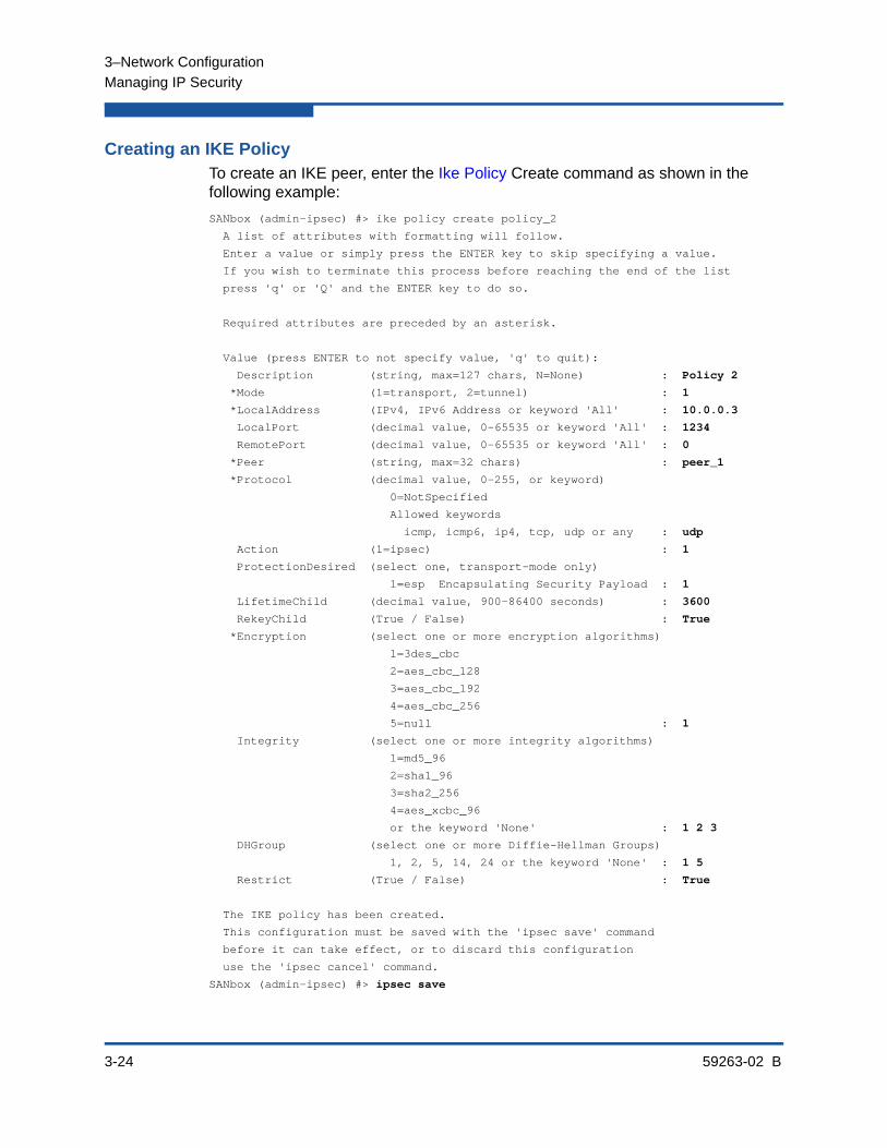
3–Network Configuration
Managing IP Security
3-24 59263-02 B
Creating an IKE PolicyTo create an IKE peer, enter the Ike Policy Create command as shown in the following example:
SANbox (admin-ipsec) #> ike policy create policy_2
A list of attributes with formatting will follow.
Enter a value or simply press the ENTER key to skip specifying a value.
If you wish to terminate this process before reaching the end of the list
press 'q' or 'Q' and the ENTER key to do so.
Required attributes are preceded by an asterisk.
Value (press ENTER to not specify value, 'q' to quit):
Description (string, max=127 chars, N=None) : Policy 2
*Mode (1=transport, 2=tunnel) : 1
*LocalAddress (IPv4, IPv6 Address or keyword 'All' : 10.0.0.3
LocalPort (decimal value, 0-65535 or keyword 'All' : 1234
RemotePort (decimal value, 0-65535 or keyword 'All' : 0
*Peer (string, max=32 chars) : peer_1
*Protocol (decimal value, 0-255, or keyword)
0=NotSpecified
Allowed keywords
icmp, icmp6, ip4, tcp, udp or any : udp
Action (1=ipsec) : 1
ProtectionDesired (select one, transport-mode only)
1=esp Encapsulating Security Payload : 1
LifetimeChild (decimal value, 900-86400 seconds) : 3600
RekeyChild (True / False) : True
*Encryption (select one or more encryption algorithms)
1=3des_cbc
2=aes_cbc_128
3=aes_cbc_192
4=aes_cbc_256
5=null : 1
Integrity (select one or more integrity algorithms)
1=md5_96
2=sha1_96
3=sha2_256
4=aes_xcbc_96
or the keyword 'None' : 1 2 3
DHGroup (select one or more Diffie-Hellman Groups)
1, 2, 5, 14, 24 or the keyword 'None' : 1 5
Restrict (True / False) : True
The IKE policy has been created.
This configuration must be saved with the 'ipsec save' command
before it can take effect, or to discard this configuration
use the 'ipsec cancel' command.
SANbox (admin-ipsec) #> ipsec save

3–Network Configuration
Managing IP Security
59263-02 B 3-25
Deleting an IKE PolicyTo delete an IKE policy, enter the Ike Policy Delete command as shown in the following example:
SANbox #> admin start
SANbox (admin) #> ipsec edit
SANbox (admin-ipsec) #> ike policy delete policy_1
The IKE policy will be deleted. Please confirm (y/n): [n] y
SANbox (admin-ipsec) #> ipsec save
The IPsec configuration will be saved and activated.
Please confirm (y/n): [n] y
Modifying an IKE PolicyTo modify an existing IKE policy, enter the Ike Policy Edit command in an Admin session and an Ipsec Edit session as shown in the following example. An asterisk (*) indicates a required entry.
SANbox (admin-ipsec) #> ike policy edit policy_1
A list of attributes with formatting and current values will follow.
Enter a new value or simply press the ENTER key to accept the current value.
If you wish to terminate this process before reaching the end of the list
press 'q' or 'Q' and the ENTER key to do so.
Required attributes are preceded by an asterisk.
Current Values:
Description Policy 1
Mode tunnel
LocalAddress 10.0.0.6
LocalPort 456
RemotePort 0 (All)
Action ipsec
LifetimeChild 3600 (seconds)
RekeyChild True
Restrict False
New Value (press ENTER to not specify value, 'q' to quit, 'n' for none):
Description (string, max=127 chars, N=None) : Policy 1a
*Mode (1=transport, 2=tunnel) : 1
*LocalAddress (IPv4, IPv6 Address or keyword 'All' :
LocalPort (decimal value, 0-65535 or keyword 'All' :
RemotePort (decimal value, 0-65535 or keyword 'All' :
*Peer (string, max=32 chars) : peer_2
*Protocol (decimal value, 0-255, or keyword)
0=NotSpecified
Allowed keywords
icmp, icmp6, ip4, tcp, udp or any : udp
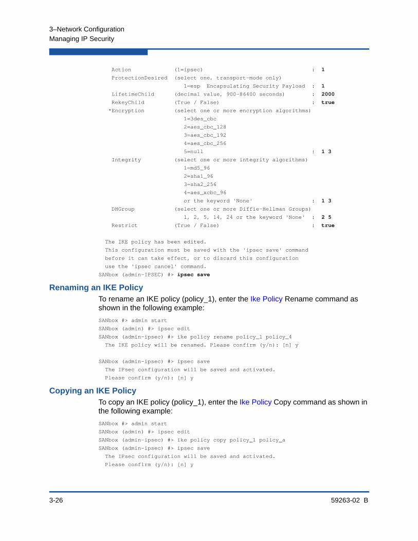
3–Network Configuration
Managing IP Security
3-26 59263-02 B
Action (1=ipsec) : 1
ProtectionDesired (select one, transport-mode only)
1=esp Encapsulating Security Payload : 1
LifetimeChild (decimal value, 900-86400 seconds) : 2000
RekeyChild (True / False) : true
*Encryption (select one or more encryption algorithms)
1=3des_cbc
2=aes_cbc_128
3=aes_cbc_192
4=aes_cbc_256
5=null : 1 3
Integrity (select one or more integrity algorithms)
1=md5_96
2=sha1_96
3=sha2_256
4=aes_xcbc_96
or the keyword 'None' : 1 3
DHGroup (select one or more Diffie-Hellman Groups)
1, 2, 5, 14, 24 or the keyword 'None' : 2 5
Restrict (True / False) : true
The IKE policy has been edited.
This configuration must be saved with the 'ipsec save' command
before it can take effect, or to discard this configuration
use the 'ipsec cancel' command.
SANbox (admin-IPSEC) #> ipsec save
Renaming an IKE PolicyTo rename an IKE policy (policy_1), enter the Ike Policy Rename command as shown in the following example:
SANbox #> admin start
SANbox (admin) #> ipsec edit
SANbox (admin-ipsec) #> ike policy rename policy_1 policy_4
The IKE policy will be renamed. Please confirm (y/n): [n] y
SANbox (admin-ipsec) #> ipsec save
The IPsec configuration will be saved and activated.
Please confirm (y/n): [n] y
Copying an IKE PolicyTo copy an IKE policy (policy_1), enter the Ike Policy Copy command as shown in the following example:
SANbox #> admin start
SANbox (admin) #> ipsec edit
SANbox (admin-ipsec) #> ike policy copy policy_1 policy_a
SANbox (admin-ipsec) #> ipsec save
The IPsec configuration will be saved and activated.
Please confirm (y/n): [n] y
3–Network Configuration
Managing IP Security
59263-02 B 3-27
Resetting the IP Security ConfigurationResetting the IP Security configuration deletes all IP security policies, IP security associations, IKE peers, and IKE policies from the switch. There are two ways to do this. Within an Ipsec Edit session, enter the Ipsec Clear command, then save the changes as shown in the following example:
SANbox #> admin start
SANbox (admin) #> ipsec edit
SANbox (admin-ipsec) #> ipsec clear
SANbox (admin-ipsec) #> ipsec save
The IPsec configuration will be saved and activated.
Please confirm (y/n): [n] y
The Reset Ipsec command deletes all security polices, security associations, IKE peers, and IKE policies from the switch, but does not require an Ipsec Edit session.
SANbox #> admin start
SANbox (admin) #> reset ipsec
The IPsec configuration will be reset and the default values activated.
Please confirm (y/n): [n] y
Reset and activation in progress ....
The Reset Ike command deletes all IKE peers and policies from the IKE database.

3–Network Configuration
Managing IP Security
3-28 59263-02 B
59263-02 B 4-1
4 Switch Configuration
Switch configuration consists of the following tasks:
Displaying Switch Information
Managing Switch Services
Managing Switch Configurations
Paging a Switch
Setting the Date and Time
Resetting a Switch
Installing Firmware
Testing a Switch
Verifying and Tracing Fibre Channel Connections
Managing Switch Feature Upgrades
Managing Idle Session Timers
Displaying Switch InformationYou can display the following types of the switch information:
Name Server Information
Switch Operational Information
System Process Information
Elapsed Time Between Resets
Configuration Information
Hardware Information
Firmware Information
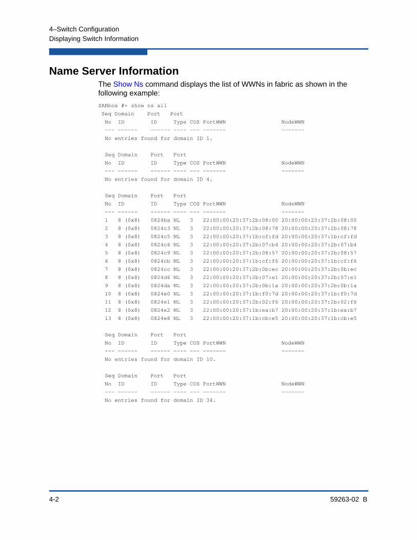
4–Switch Configuration
Displaying Switch Information
4-2 59263-02 B
Name Server InformationThe Show Ns command displays the list of WWNs in fabric as shown in the following example:
SANbox #> show ns all
Seq Domain Port Port
No ID ID Type COS PortWWN NodeWWN
--- ------ ------ ---- --- ------- -------
No entries found for domain ID 1.
Seq Domain Port Port
No ID ID Type COS PortWWN NodeWWN
--- ------ ------ ---- --- ------- -------
No entries found for domain ID 4.
Seq Domain Port Port
No ID ID Type COS PortWWN NodeWWN
--- ------ ------ ---- --- ------- -------
1 8 (0x8) 0824ba NL 3 22:00:00:20:37:2b:08:00 20:00:00:20:37:2b:08:00
2 8 (0x8) 0824c3 NL 3 22:00:00:20:37:2b:08:78 20:00:00:20:37:2b:08:78
3 8 (0x8) 0824c5 NL 3 22:00:00:20:37:1b:cf:fd 20:00:00:20:37:1b:cf:fd
4 8 (0x8) 0824c6 NL 3 22:00:00:20:37:2b:07:b4 20:00:00:20:37:2b:07:b4
5 8 (0x8) 0824c9 NL 3 22:00:00:20:37:2b:08:57 20:00:00:20:37:2b:08:57
6 8 (0x8) 0824cb NL 3 22:00:00:20:37:1b:cf:f6 20:00:00:20:37:1b:cf:f6
7 8 (0x8) 0824cc NL 3 22:00:00:20:37:2b:0b:ec 20:00:00:20:37:2b:0b:ec
8 8 (0x8) 0824d6 NL 3 22:00:00:20:37:2b:07:e1 20:00:00:20:37:2b:07:e1
9 8 (0x8) 0824da NL 3 22:00:00:20:37:2b:0b:1a 20:00:00:20:37:2b:0b:1a
10 8 (0x8) 0824e0 NL 3 22:00:00:20:37:1b:f0:7d 20:00:00:20:37:1b:f0:7d
11 8 (0x8) 0824e1 NL 3 22:00:00:20:37:2b:02:f6 20:00:00:20:37:2b:02:f6
12 8 (0x8) 0824e2 NL 3 22:00:00:20:37:1b:ea:b7 20:00:00:20:37:1b:ea:b7
13 8 (0x8) 0824e8 NL 3 22:00:00:20:37:1b:cb:e5 20:00:00:20:37:1b:cb:e5
Seq Domain Port Port
No ID ID Type COS PortWWN NodeWWN
--- ------ ------ ---- --- ------- -------
No entries found for domain ID 10.
Seq Domain Port Port
No ID ID Type COS PortWWN NodeWWN
--- ------ ------ ---- --- ------- -------
No entries found for domain ID 34.

4–Switch Configuration
Displaying Switch Information
59263-02 B 4-3
Switch Operational InformationThe Show Switch command displays a variety of switch operational information. These include the switch WWN, domain ID, firmware version, administrative state, and operational state as shown in the following example:
SANbox #> show switch
Switch Information
------------------
SymbolicName SANbox
SwitchWWN 10:00:00:c0:dd:00:bc:56
BootVersion Vx.x.x.x-0 (day month date time year)
CreditPool 0
DomainID 19 (0x13)
FirstPortAddress 130000
FlashSize - MBytes 128
LogFilterLevel Critical
MaxPorts 24
NumberOfResets 15
ReasonForLastReset PowerUp
ActiveImageVersion - build date Vx.x.x.0 (day month date time year)
PendingImageVersion - build date Vx.x.x.0 (day month date time year)
ActiveConfiguration default
AdminState Online
AdminModeActive False
BeaconOnStatus Off
OperationalState Online
PrincipalSwitchRole False
POSTFaultCode 00000000
POSTStatus Passed
TestFaultCode 00000000
TestStatus NeverRun
BoardTemp (1) - Degrees Celsius 32
SwitchTemperatureStatus Normal

4–Switch Configuration
Displaying Switch Information
4-4 59263-02 B
System Process InformationThe Ps command displays system process information to help you determine what processes are running and CPU usage. The following example displays current system processes.
SANbox #> ps
PID PPID %CPU %MEM TIME ELAPSED COMMAND
244 224 0.0 0.3 00:00:04 2-03:02:31 cns
245 224 0.0 0.3 00:00:06 2-03:02:31 ens
246 224 0.0 0.3 00:00:09 2-03:02:31 dlog
247 224 0.0 0.6 00:00:33 2-03:02:31 ds
248 224 0.3 2.8 00:09:59 2-03:02:31 mgmtApp
249 224 0.0 0.3 00:00:16 2-03:02:31 sys2swlog
251 224 0.0 0.4 00:00:06 2-03:02:30 fc2
252 224 0.0 0.6 00:00:16 2-03:02:30 nserver
253 224 0.0 0.8 00:00:08 2-03:02:30 PortApp
254 224 0.0 0.5 00:00:03 2-03:02:30 qfsApp
255 224 0.0 0.5 00:00:09 2-03:02:30 mserver
256 224 0.0 0.7 00:00:06 2-03:02:30 eport
257 224 0.0 0.6 00:00:13 2-03:02:30 zoning
282 254 0.0 0.5 00:00:00 2-03:02:26 qfsApp
284 224 0.0 0.6 00:00:08 2-03:02:26 snmpservicepath
285 282 0.0 0.5 00:00:00 2-03:02:26 qfsApp
308 224 0.0 0.8 00:00:29 2-03:02:25 cim_server
322 224 0.0 0.7 00:00:16 2-03:02:24 util
323 224 0.0 0.4 00:00:09 2-03:02:24 port_mon
324 224 0.0 0.5 00:00:07 2-03:02:24 diagAgent
325 224 0.0 0.4 00:00:03 2-03:02:24 diagExec
289 224 0.0 0.4 00:00:00 2-03:02:25 snmpd
290 224 0.0 0.5 00:00:00 2-03:02:25 snmpmain
335 290 0.0 0.5 00:00:00 2-03:02:23 snmpmain
336 335 0.0 0.5 00:00:00 2-03:02:23 snmpmain
The column titles are as follows:
PID–Process identifier
PPID–Parent process identifier
%CPU–Percentage CPU usage
%MEM–Percentage memory usage
TIME–Actual processing time
ELAPSED–Elapsed time since the process started
COMMAND–The command that initiated the process.

4–Switch Configuration
Displaying Switch Information
59263-02 B 4-5
Elapsed Time Between ResetsThe Uptime command displays the elapsed time since the switch was last reset and the reset method. A hot reset or non-disruptive firmware activation does not reset the elapsed time reported by this command. The following example displays the time since the last reset.
SANbox #> uptime
Elapsed up time : 0 day(s), 2 hour(s), 28 min(s), 44 sec(s)
Reason last reset: NormalReset
Configuration InformationThe Show Config command displays a variety of configuration information at the port and switch levels. In addition to the basic switch configurations, the Show Config command displays parameters that control how data is maintained in the security and zoning databases. The Show Config command displays the following types of information:
Switch Configuration Parameters
Zoning Configuration Parameters
Security Configuration Parameters
Refer to “Displaying Port Information” on page 5-1 for information about displaying port configuration information.
Switch Configuration ParametersEnter the Show Config Switch command to display the switch configuration parameters. These parameters determine the operational characteristics of the switch. Refer to Table 13-24 for a description these parameters.
SANbox #> show config switch
Configuration Name: default
-------------------
Switch Configuration Information
--------------------------------
AdminState Online
BroadcastEnabled False
InbandEnabled True
FDMIEnabled False
FDMIEntries 10
DefaultDomainID 19 (0x13)
DomainIDLock True
SymbolicName sw108
R_A_TOV 10000
E_D_TOV 2000
PrincipalPriority 254
ConfigDescription Default Config
ConfigLastSavedBy admin@OB-session5
ConfigLastSavedOn day month date time year

4–Switch Configuration
Displaying Switch Information
4-6 59263-02 B
InteropMode Standard
Zoning Configuration ParametersEnter the Show Config Zoning command to display zoning configuration parameters. These parameters determine how zoning is applied to the switch. Refer to Table 13-26 for a description of these parameters.
SANbox #> show config zoning
Configuration Name: default
-------------------
Zoning Configuration Information
--------------------------------
MergeAutoSave True
DefaultZone Allow
DiscardInactive False
Security Configuration ParametersEnter the Show Config Security command to display security configuration and port binding parameters. These parameters determine how security is applied to the switch. Refer to Table 13-22 for a description of the switch security configuration parameters. Refer to Table 13-23 for a description of the port binding parameters.
SANbox #> show config security
Configuration Name: default
-------------------
Switch Security Configuration Information
-----------------------------------------
FabricBindingEnabled False
AutoSave True
Port Binding Status WWN
---- -------------- ---
0 True 10:20:30:40:50:60:70:80
1 True 10:20:30:40:50:60:70:80
2 False No port binding entries found.
3 True 10:20:30:40:50:60:70:80
4 True 10:20:30:40:50:60:70:80
5 False No port binding entries found.
6 True 10:20:30:40:50:60:70:81
7 False No port binding entries found.
8 True 10:20:30:40:50:60:70:80
9 False No port binding entries found.
10 False No port binding entries found.
11 False No port binding entries found.
12 False No port binding entries found.
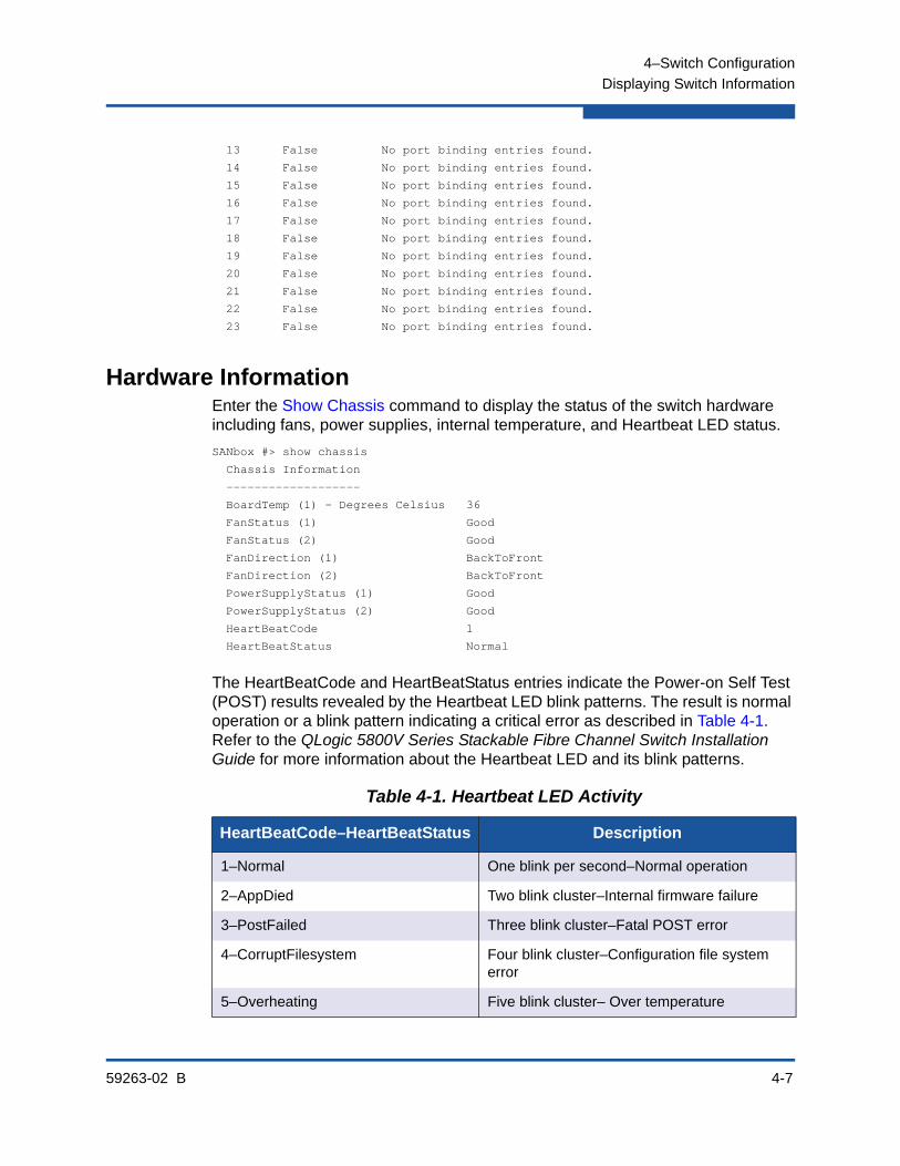
4–Switch Configuration
Displaying Switch Information
59263-02 B 4-7
13 False No port binding entries found.
14 False No port binding entries found.
15 False No port binding entries found.
16 False No port binding entries found.
17 False No port binding entries found.
18 False No port binding entries found.
19 False No port binding entries found.
20 False No port binding entries found.
21 False No port binding entries found.
22 False No port binding entries found.
23 False No port binding entries found.
Hardware InformationEnter the Show Chassis command to display the status of the switch hardware including fans, power supplies, internal temperature, and Heartbeat LED status.
SANbox #> show chassis
Chassis Information
-------------------
BoardTemp (1) - Degrees Celsius 36
FanStatus (1) Good
FanStatus (2) Good
FanDirection (1) BackToFront
FanDirection (2) BackToFront
PowerSupplyStatus (1) Good
PowerSupplyStatus (2) Good
HeartBeatCode 1
HeartBeatStatus Normal
The HeartBeatCode and HeartBeatStatus entries indicate the Power-on Self Test (POST) results revealed by the Heartbeat LED blink patterns. The result is normal operation or a blink pattern indicating a critical error as described in Table 4-1. Refer to the QLogic 5800V Series Stackable Fibre Channel Switch Installation Guide for more information about the Heartbeat LED and its blink patterns.
Table 4-1. Heartbeat LED Activity
HeartBeatCode–HeartBeatStatus Description
1–Normal One blink per second–Normal operation
2–AppDied Two blink cluster–Internal firmware failure
3–PostFailed Three blink cluster–Fatal POST error
4–CorruptFilesystem Four blink cluster–Configuration file system error
5–Overheating Five blink cluster– Over temperature

4–Switch Configuration
Displaying Switch Information
4-8 59263-02 B
Firmware InformationEnter the Show Version command to display a summary of switch identity information including the firmware version. The following is an example of the Show Version command:
SANbox #> show version
*****************************************************
* *
* Command Line Interface SHell (CLISH) *
* *
*****************************************************
SystemDescription QLogic 5800V FC Switch
HostName <undefined>
EthIPv4NetworkAddress 10.20.11.192
EthIPv6NetworkAddress ::
MACAddress 00:c0:dd:00:71:ee
WorldWideName 10:00:00:c0:dd:00:71:ed
ChassisSerialNumber 033100024
SymbolicName SANbox
ActiveSWVersion V8.0.x.x.xx.xx
ActiveTimestamp day month date time year
POSTStatus Passed
LicensedPorts 24
SwitchMode Full Fabric
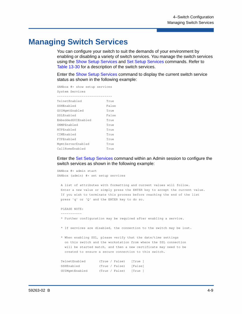
4–Switch Configuration
Managing Switch Services
59263-02 B 4-9
Managing Switch ServicesYou can configure your switch to suit the demands of your environment by enabling or disabling a variety of switch services. You manage the switch services using the Show Setup Services and Set Setup Services commands. Refer to Table 13-30 for a description of the switch services.
Enter the Show Setup Services command to display the current switch service status as shown in the following example:
SANbox #> show setup services
System Services
-----------------------------
TelnetEnabled True
SSHEnabled False
GUIMgmtEnabled True
SSLEnabled False
EmbeddedGUIEnabled True
SNMPEnabled True
NTPEnabled True
CIMEnabled True
FTPEnabled True
MgmtServerEnabled True
CallHomeEnabled True
Enter the Set Setup Services command within an Admin session to configure the switch services as shown in the following example:
SANbox #> admin start
SANbox (admin) #> set setup services
A list of attributes with formatting and current values will follow.
Enter a new value or simply press the ENTER key to accept the current value.
If you wish to terminate this process before reaching the end of the list
press 'q' or 'Q' and the ENTER key to do so.
PLEASE NOTE:
-----------
* Further configuration may be required after enabling a service.
* If services are disabled, the connection to the switch may be lost.
* When enabling SSL, please verify that the date/time settings
on this switch and the workstation from where the SSL connection
will be started match, and then a new certificate may need to be
created to ensure a secure connection to this switch.
TelnetEnabled (True / False) [True ]
SSHEnabled (True / False) [False]
GUIMgmtEnabled (True / False) [True ]

4–Switch Configuration
Managing Switch Configurations
4-10 59263-02 B
SSLEnabled (True / False) [False]
EmbeddedGUIEnabled (True / False) [True ]
SNMPEnabled (True / False) [True ]
NTPEnabled (True / False) [False]
CIMEnabled (True / False) [False]
FTPEnabled (True / False) [True ]
MgmtServerEnabled (True / False) [True ]
CallHomeEnabled (True / False) [True ]
Do you want to save and activate this services setup? (y/n): [n]
Managing Switch ConfigurationsThe switch configuration determines the basic operational characteristics of the switch. A switch can save up to 10 configurations including the default configuration, named Default Config. The current switch operating characteristics are determined by the active configuration. Only one configuration can be active at one time.
Each switch configuration contains switch, port, port threshold alarm, and zoning configuration components. Managing Switch Configurations describes the following tasks:
Displaying a List of Switch Configurations
Activating a Switch Configuration
Copying a Switch Configuration
Deleting a Switch Configuration
Modifying a Switch Configuration
Backing Up and Restoring a Switch Configuration
Displaying a List of Switch ConfigurationsEnter the Config List command to display the configurations stored on the switch as show in the following example. Notice that the Config List command does not require an Admin session.
SANbox #> config list
Current list of configurations
------------------------------
default
config_1
config_2

4–Switch Configuration
Managing Switch Configurations
59263-02 B 4-11
Activating a Switch ConfigurationEnter the Config Activate command in an Admin session to activate a switch configuration (config_1) as shown in the following example:
SANbox (admin) config activate config_1
Copying a Switch ConfigurationEnter the Config Copy command in an Admin session to create a copy of an existing configuration as shown in the following example:
SANbox (admin) config copy config_1 config_2
Deleting a Switch ConfigurationEnter the Config Delete command in an Admin session to delete a configuration from the switch as shown in the following example. You cannot delete the active configuration nor the default configuration (Default Config).
SANbox (admin) config delete config_2
Modifying a Switch ConfigurationTo modify a switch configuration, you must open an Admin session with the Admin Start command. An Admin session prevents other accounts from making changes at the same time through Telnet, Enterprise Fabric Suite, or another management application. You must also open a Config Edit session with the Config Edit command and indicate which configuration you want to modify. If you do not specify a configuration name the active configuration is assumed.
The Config Edit session provides access to the Set Config commands with which you make modifications to the port, switch, port threshold alarm, or zoning configuration components as shown:
SANbox #> admin start
SANbox (admin) #> config edit
The config named default is being edited.
SANbox (admin-config)#> set config port . . .
SANbox (admin-config)#> set config switch . . .
SANbox (admin-config)#> set config threshold . . .
SANbox (admin-config)#> set config zoning . . .
SANbox (admin-config)#> set config security . . .
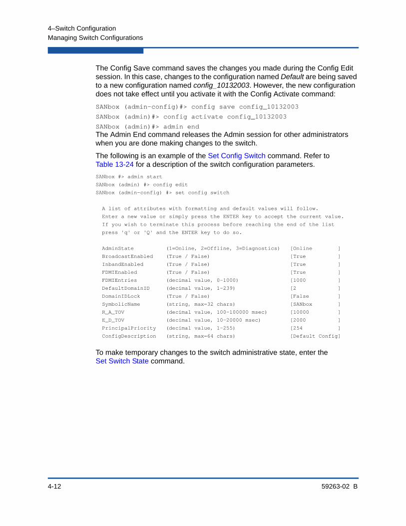
4–Switch Configuration
Managing Switch Configurations
4-12 59263-02 B
The Config Save command saves the changes you made during the Config Edit session. In this case, changes to the configuration named Default are being saved to a new configuration named config_10132003. However, the new configuration does not take effect until you activate it with the Config Activate command:
SANbox (admin-config)#> config save config_10132003
SANbox (admin)#> config activate config_10132003
SANbox (admin)#> admin endThe Admin End command releases the Admin session for other administrators when you are done making changes to the switch.
The following is an example of the Set Config Switch command. Refer to Table 13-24 for a description of the switch configuration parameters.
SANbox #> admin start
SANbox (admin) #> config edit
SANbox (admin-config) #> set config switch
A list of attributes with formatting and default values will follow.
Enter a new value or simply press the ENTER key to accept the current value.
If you wish to terminate this process before reaching the end of the list
press 'q' or 'Q' and the ENTER key to do so.
AdminState (1=Online, 2=Offline, 3=Diagnostics) [Online ]
BroadcastEnabled (True / False) [True ]
InbandEnabled (True / False) [True ]
FDMIEnabled (True / False) [True ]
FDMIEntries (decimal value, 0-1000) [1000 ]
DefaultDomainID (decimal value, 1-239) [2 ]
DomainIDLock (True / False) [False ]
SymbolicName (string, max=32 chars) [SANbox ]
R_A_TOV (decimal value, 100-100000 msec) [10000 ]
E_D_TOV (decimal value, 10-20000 msec) [2000 ]
PrincipalPriority (decimal value, 1-255) [254 ]
ConfigDescription (string, max=64 chars) [Default Config]
To make temporary changes to the switch administrative state, enter the Set Switch State command.

4–Switch Configuration
Managing Switch Configurations
59263-02 B 4-13
Backing Up and Restoring a Switch ConfigurationSuccessful management of switches and fabrics depends on the effective use of switch configurations. Backing up and restoring a configuration is useful to protect your work or for use as a template in configuring other switches. Backing up and restoring the switch configuration involves the following:
Creating the Backup File
Downloading the Configuration File
Restoring the Configuration File
Creating the Backup FileThe Config Backup command creates a file on the switch, named configdata. This file can be used to restore a switch configuration only from the command line interface; it cannot be used to restore a switch using Enterprise Fabric Suite.
SANbox #> config backupThe configdata file contains the following switch configuration information:
All named switch configurations including port, switch, port threshold alarm and zoning configurations.
All SNMP and network information defined with the Set Setup command.
The zoning database includes all zone sets, zones, and aliases.
The security database except the group primary and secondary secrets.
The Call Home database and Call Home service configuration.
NOTE:
Configuration backup files are deleted from the switch during a power cycle or switch reset.
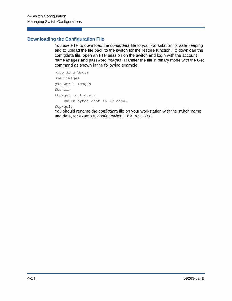
4–Switch Configuration
Managing Switch Configurations
4-14 59263-02 B
Downloading the Configuration FileYou use FTP to download the configdata file to your workstation for safe keeping and to upload the file back to the switch for the restore function. To download the configdata file, open an FTP session on the switch and login with the account name images and password images. Transfer the file in binary mode with the Get command as shown in the following example:
>ftp ip_address
user:images
password: images
ftp>bin
ftp>get configdata
xxxxx bytes sent in xx secs.
ftp>quitYou should rename the configdata file on your workstation with the switch name and date, for example, config_switch_169_10112003.
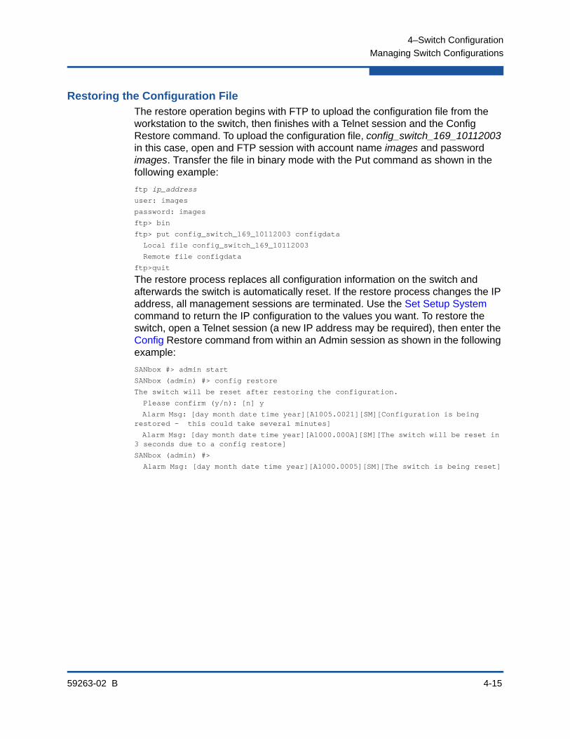
4–Switch Configuration
Managing Switch Configurations
59263-02 B 4-15
Restoring the Configuration FileThe restore operation begins with FTP to upload the configuration file from the workstation to the switch, then finishes with a Telnet session and the Config Restore command. To upload the configuration file, config_switch_169_10112003 in this case, open and FTP session with account name images and password images. Transfer the file in binary mode with the Put command as shown in the following example:
ftp ip_address
user: images
password: images
ftp> bin
ftp> put config_switch_169_10112003 configdata
Local file config_switch_169_10112003
Remote file configdata
ftp>quit
The restore process replaces all configuration information on the switch and afterwards the switch is automatically reset. If the restore process changes the IP address, all management sessions are terminated. Use the Set Setup System command to return the IP configuration to the values you want. To restore the switch, open a Telnet session (a new IP address may be required), then enter the Config Restore command from within an Admin session as shown in the following example:
SANbox #> admin start
SANbox (admin) #> config restore
The switch will be reset after restoring the configuration.
Please confirm (y/n): [n] y
Alarm Msg: [day month date time year][A1005.0021][SM][Configuration is being restored - this could take several minutes]
Alarm Msg: [day month date time year][A1000.000A][SM][The switch will be reset in 3 seconds due to a config restore]
SANbox (admin) #>
Alarm Msg: [day month date time year][A1000.0005][SM][The switch is being reset]

4–Switch Configuration
Paging a Switch
4-16 59263-02 B
Paging a SwitchTo help you locate a particular switch in a rack of switches, you can turn on the beacon feature with the Set Beacon command. This causes all port Logged-In LEDs to flash in unison. The following is an example of how to turn the beacon on and off.
SANbox #> set beacon on
SANbox $> set beacon off
Setting the Date and TimeThe switch date and time can be set explicitly using the Date command or it can be set automatically through a Network Time Protocol (NTP) server. The Date command also displays the current time. Unlike the Date command, the NTP server also synchronizes the date and time on the switch with the date and time on the workstation, which is required for Secure Socket Layer (SSL) connections.
If you are using the date command, you can set the time zone using the Set Timezone command. The default time zone is Universal Time (UTC) also known as Greenwich Mean Time (GMT). Changing the time zone converts the current time to the time in the new time zone. For this reason, if you are not using an NTP server, set the time zone first, then set the date and time.
See the following date and time management examples:
Displaying the Date and Time
Setting the Date and Time Explicitly
Setting the Date and Time through NTP
Displaying the Date and TimeEnter the Date command to display the date and time as shown in the following example:
SANbox #> date
Mon Apr 07 07:51:24 200x
NOTE:
To set the date with the Date command, the NTP client must be disabled. For information about disabling the NTPClientEnabled parameter, refer to the Set Setup System command.

4–Switch Configuration
Setting the Date and Time
59263-02 B 4-17
Setting the Date and Time ExplicitlyTo set the switch date and time explicitly, use the Set Timezone and Date commands. To change the time zone (to America/North Dakota, for example), enter the Set Timezone command in an Admin session, as shown in the following example:
SANbox #> admin start
SANbox (admin) #> set timezone
Africa America
Antarctica Asia
Atlantic Australia
Europe Indian
Pacific UTC
Press ENTER for more options or 'q' to make a selection.
America/Grenada America/Guadeloupe
America/Guatemala America/Guayaquil
America/Guyana America/Halifax
America/Havana America/Hermosillo
America/Indiana America/Indianapolis
.
.
.
America/Monterrey America/Montevideo
America/Montreal America/Montserrat
America/Nassau America/New_York
America/Nipigon America/Nome
America/Noronha America/North_Dakota
America/Panama America/Pangnirtung
Press ENTER for more options or 'q' to make a selection.
q
Enter selection (or 'q' to quit): america/north_dakota
America/North_Dakota/Center
Enter selection (or 'q' to quit): america/north_dakota/center
To set the date and time (January 31, 10:15 AM, 2008), enter the date command, as shown in the following example:
SANbox (admin) #> date 013110152008
SANbox (admin) #> date
Thu Jan 31 10:15:03 america/north_dakota/center 2008

4–Switch Configuration
Setting the Date and Time
4-18 59263-02 B
Setting the Date and Time through NTPAn NTP server can automatically set the switch date and time. To configure the switch to use an NTP server, enter the Set Setup System Ntp command in an Admin session to enable the NTP client on the switch and specify the NPT server IP address, as shown in the following example:
SANbox (admin) #> set setup system ntp
A list of attributes with formatting and current values will follow.
Enter a new value or simply press the ENTER key to accept the current value.
If you wish to terminate this process before reaching the end of the list
press 'q' or 'Q' and the ENTER key to do so.
Current Values:
NTPClientEnabled False
NTPServerDiscovery Static
NTPServerAddress 10.20.10.10
New Value (press ENTER to accept current value, 'q' to quit, 'n' for none):
NTPClientEnabled (True / False) : True
NTPServerDiscovery (1=Static, 2=Dhcp, 3=Dhcpv6) :
NTPServerAddress (hostname, IPv4, or IPv6 Address) : 10.20.3.4
Do you want to save and activate this system setup? (y/n): [n] y
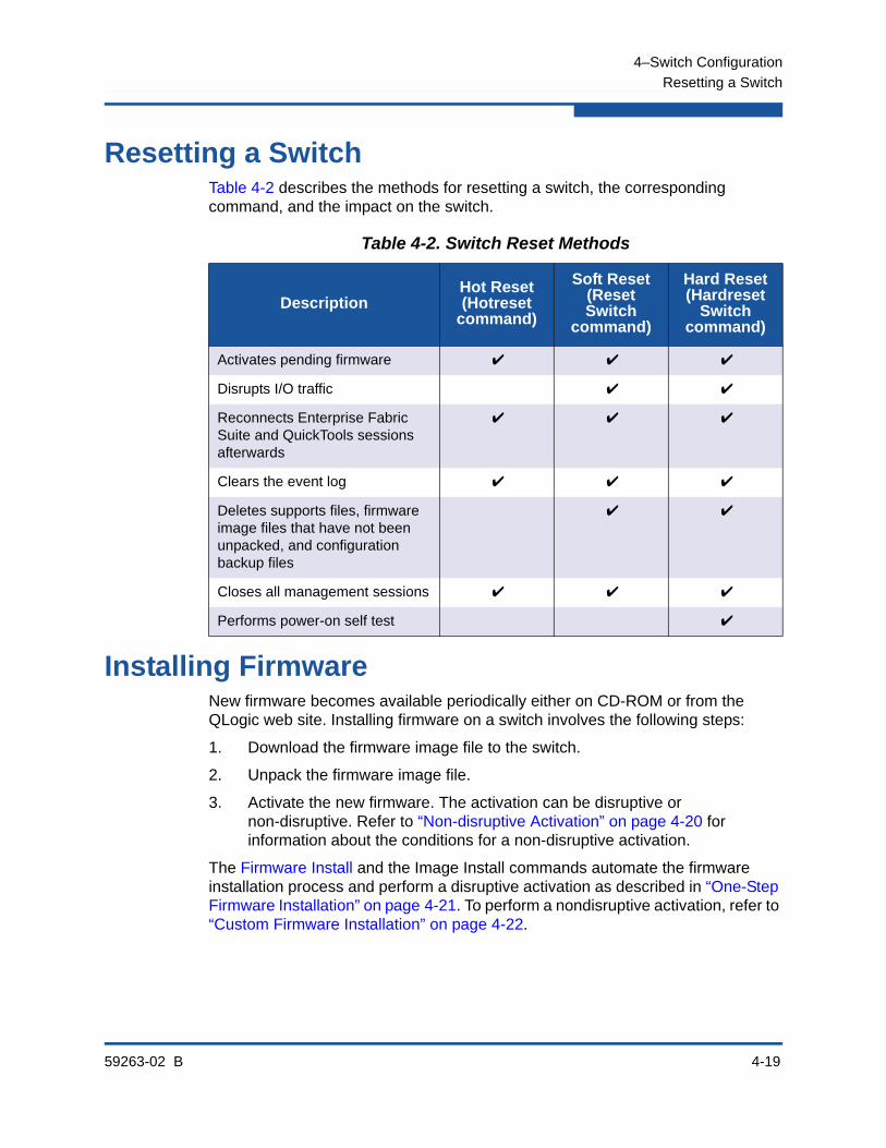
4–Switch Configuration
Resetting a Switch
59263-02 B 4-19
Resetting a SwitchTable 4-2 describes the methods for resetting a switch, the corresponding command, and the impact on the switch.
Installing FirmwareNew firmware becomes available periodically either on CD-ROM or from the QLogic web site. Installing firmware on a switch involves the following steps:
1. Download the firmware image file to the switch.
2. Unpack the firmware image file.
3. Activate the new firmware. The activation can be disruptive or non-disruptive. Refer to “Non-disruptive Activation” on page 4-20 for information about the conditions for a non-disruptive activation.
The Firmware Install and the Image Install commands automate the firmware installation process and perform a disruptive activation as described in “One-Step Firmware Installation” on page 4-21. To perform a nondisruptive activation, refer to “Custom Firmware Installation” on page 4-22.
Table 4-2. Switch Reset Methods
DescriptionHot Reset(Hotreset
command)
Soft Reset(Reset Switch
command)
Hard Reset(Hardreset
Switch command)
Activates pending firmware ✔ ✔ ✔
Disrupts I/O traffic ✔ ✔
Reconnects Enterprise Fabric Suite and QuickTools sessions afterwards
✔ ✔ ✔
Clears the event log ✔ ✔ ✔
Deletes supports files, firmware image files that have not been unpacked, and configuration backup files
✔ ✔
Closes all management sessions ✔ ✔ ✔
Performs power-on self test ✔
4–Switch Configuration
Installing Firmware
4-20 59263-02 B
Non-disruptive ActivationYou can load and activate firmware upgrades on an operating switch without disrupting data traffic or having to re-initialize attached devices. If the non-disruptive activation fails, you will usually be prompted to try again later. Otherwise, the switch will perform a disruptive activation. A disruptive activation interrupts Fibre Channel data traffic on the switch, while a non-disruptive activation does not. For information about non-disruptive firmware versions, see the Firmware Release Notes.
To ensure a successful non-disruptive activation, you should first satisfy the following conditions:
No changes are being made to switches in the fabric including powering up, powering down, disconnecting or connecting ISLs, changing switch configurations, or installing firmware.
No port on the switch is in the diagnostic state.
No Zoning Edit sessions are open on the switch.
No changes are being made to attached devices including powering up, powering down, disconnecting, connecting, and HBA configuration changes.
For a fabric in which one or more switches are running firmware prior to version 8.0, only one Enterprise Fabric Suite session can be open.
Install firmware on one switch at a time in the fabric. If you are installing firmware on one switch, wait two minutes after the activation is complete before installing firmware on a second switch.
Ports that change states during the non-disruptive activation, will be reset. When the non-disruptive activation is complete, Enterprise Fabric Suite and QuickTools sessions reconnect automatically. However, Telnet sessions must be restarted manually.
NOTE:
After upgrading firmware that includes changes to QuickTools, a QuickTools session that was open during the upgrade may indicate that the new firmware is not supported. To correct this, close the QuickTools session and the browser window, then open a new QuickTools session.
4–Switch Configuration
Installing Firmware
59263-02 B 4-21
One-Step Firmware InstallationThe Firmware Install and Image Install commands download the firmware image file from an FTP or TFTP server to the switch, unpacks the image file, and performs a disruptive activation in one step. The one-step installation process prompts you to enter the following:
The file transfer protocol (FTP or TFTP)
IP address of the remote host
An account name and password on the remote host (FTP only)
Pathname for the firmware image file
1. Enter the following commands to download the firmware from a remote host to the switch, install the firmware, then reset the switch to activate the firmware.
SANbox #> admin start
SANbox #> firmware install
The switch will be reset. This process will cause a disruption to I/O traffic.
Continuing with this action will terminate all management sessions,including any Telnet sessions. When the firmware activation is complete, you may log in to the switch again.
Do you want to continue? [y/n]: y
Press 'q' and the ENTER key to abort this command.
2. Enter your choice for the file transfer protocol with which to download the firmware image file. FTP requires an user account and a password; TFTP does not.
FTP or TFTP : ftp
3. Enter your account name on the remote host (FTP only) and the IP address of the remote host. When prompted for the source file name, enter the path for the firmware image file.
User Account : johndoe
IP Address : 10.0.0.254
Source Filename : 8.0.00.00_epc
About to install image. Do you want to continue? [y/n] y

4–Switch Configuration
Installing Firmware
4-22 59263-02 B
4. When prompted to install the new firmware, enter Yes to continue or No to cancel. Entering Yes will disrupt traffic. This is the last opportunity to cancel.
About to install image. Do you want to continue? [y/n] yConnected to 10.20.20.200 (10.20.20.200).
220 localhost.localdomain FTP server (Version wu-2.6.1-18) ready.
5. Enter the password for your account name (FTP only).
331 Password required for johndoe.Password:******230 User johndoe logged in.
6. The firmware will now be downloaded from the remote host to the switch, installed, and activated.
Custom Firmware InstallationA custom firmware installation downloads the firmware image file from a remote host to the switch, unpacks the image file, and resets the switch in separate steps. This allows you to choose the type of switch reset and whether the activation will be disruptive (Reset Switch command) or nondisruptive (Hotreset command). The following example illustrates a custom firmware installation with a nondisruptive activation.
1. Download the firmware image file from the workstation to the switch.
If your workstation has an FTP server, you can enter the Image Fetch command:
SANbox #> admin start
SANbox (admin) #> image fetch account_name ip_address filename
If your workstation has a TFTP server, you can enter the Image TFTP command to download the firmware image file.
SANbox (admin) #> image tftp ip_address filename
4–Switch Configuration
Testing a Switch
59263-02 B 4-23
If your workstation has neither an FTP nor a TFTP server, open an FTP session and download the firmware image file by entering FTP commands:
>ftp ip_address or switchname
user:images
password: images
ftp>bin
ftp>put filename
ftp>quit
2. Display the list of firmware image files on the switch to confirm that the file was loaded.
SANbox #> admin start
SANbox (admin) $> image list
3. Unpack the firmware image file to install the new firmware in flash memory.
SANbox (admin) $> image unpack filename
4. Wait for the unpack to complete.
Image unpack command result: Passed
5. A message will prompt you to reset the switch to activate the firmware. Use the Hotreset command to attempt a non-disruptive activation.
SANbox (admin) $> hotreset
Testing a SwitchYou can test all ports on a switch using the Test Switch command. There are three test types: online, offline, and connectivity. Refer to “Testing a Port” on page 5-15 for information about testing individual and ports.
The following sections describe the test types, displaying test status, and cancelling a switch test:
Online Tests for Switches
Offline Tests for Switches
Connectivity Tests for Switches
Displaying Switch Test Status
Canceling a Switch Test

4–Switch Configuration
Testing a Switch
4-24 59263-02 B
Online Tests for SwitchesAn online test is a non-disruptive test that exercises port-to-device connections for all ports that are online. The online switch test excludes TR_Ports. The following is an example of an online test:
SANbox #> admin start
SANbox (admin) #> test switch online
A list of attributes with formatting and current values will follow. Enter a new value or simply press the ENTER key to accept the default value. If you wish to terminate this process before reaching the end of the list press 'q' or 'Q' and the ENTER key to do so.
LoopCount (decimal value, 1-4294967295) [100 ]
FrameSize (decimal value, 40-2148) [256 ]
DataPattern (32-bit hex value or 'Default') [Default]
StopOnError (True / False) [True ]
LoopForever (True / False) [False ]
Do you want to start the test? (y/n) [n] y
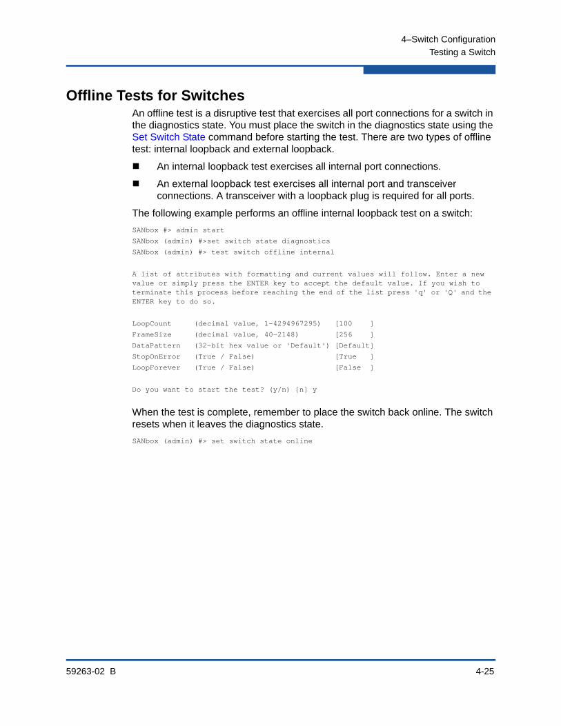
4–Switch Configuration
Testing a Switch
59263-02 B 4-25
Offline Tests for SwitchesAn offline test is a disruptive test that exercises all port connections for a switch in the diagnostics state. You must place the switch in the diagnostics state using the Set Switch State command before starting the test. There are two types of offline test: internal loopback and external loopback.
An internal loopback test exercises all internal port connections.
An external loopback test exercises all internal port and transceiver connections. A transceiver with a loopback plug is required for all ports.
The following example performs an offline internal loopback test on a switch:
SANbox #> admin start
SANbox (admin) #>set switch state diagnostics
SANbox (admin) #> test switch offline internal
A list of attributes with formatting and current values will follow. Enter a new value or simply press the ENTER key to accept the default value. If you wish to terminate this process before reaching the end of the list press 'q' or 'Q' and the ENTER key to do so.
LoopCount (decimal value, 1-4294967295) [100 ]
FrameSize (decimal value, 40-2148) [256 ]
DataPattern (32-bit hex value or 'Default') [Default]
StopOnError (True / False) [True ]
LoopForever (True / False) [False ]
Do you want to start the test? (y/n) [n] y
When the test is complete, remember to place the switch back online. The switch resets when it leaves the diagnostics state.
SANbox (admin) #> set switch state online
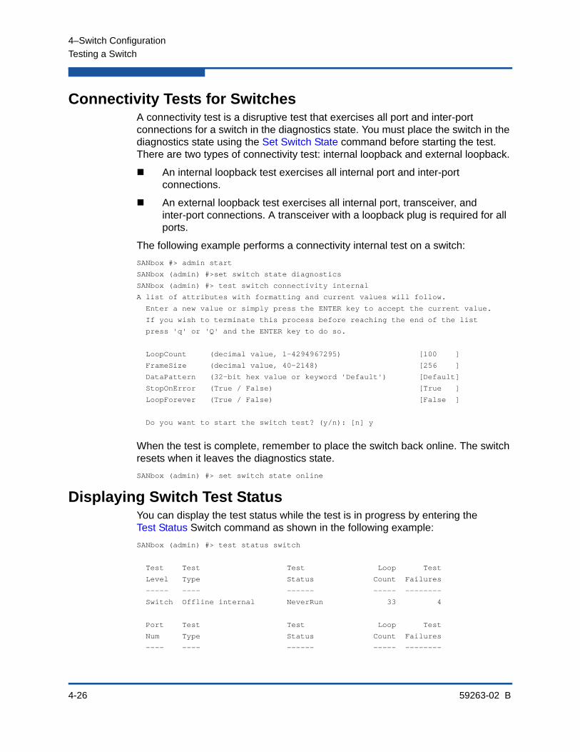
4–Switch Configuration
Testing a Switch
4-26 59263-02 B
Connectivity Tests for SwitchesA connectivity test is a disruptive test that exercises all port and inter-port connections for a switch in the diagnostics state. You must place the switch in the diagnostics state using the Set Switch State command before starting the test. There are two types of connectivity test: internal loopback and external loopback.
An internal loopback test exercises all internal port and inter-port connections.
An external loopback test exercises all internal port, transceiver, and inter-port connections. A transceiver with a loopback plug is required for all ports.
The following example performs a connectivity internal test on a switch:
SANbox #> admin start
SANbox (admin) #>set switch state diagnostics
SANbox (admin) #> test switch connectivity internal
A list of attributes with formatting and current values will follow.
Enter a new value or simply press the ENTER key to accept the current value.
If you wish to terminate this process before reaching the end of the list
press 'q' or 'Q' and the ENTER key to do so.
LoopCount (decimal value, 1-4294967295) [100 ]
FrameSize (decimal value, 40-2148) [256 ]
DataPattern (32-bit hex value or keyword 'Default') [Default]
StopOnError (True / False) [True ]
LoopForever (True / False) [False ]
Do you want to start the switch test? (y/n): [n] y
When the test is complete, remember to place the switch back online. The switch resets when it leaves the diagnostics state.
SANbox (admin) #> set switch state online
Displaying Switch Test StatusYou can display the test status while the test is in progress by entering the Test Status Switch command as shown in the following example:
SANbox (admin) #> test status switch
Test Test Test Loop Test
Level Type Status Count Failures
----- ---- ------ ----- --------
Switch Offline internal NeverRun 33 4
Port Test Test Loop Test
Num Type Status Count Failures
---- ---- ------ ----- --------

4–Switch Configuration
Testing a Switch
59263-02 B 4-27
0 Offline internal StoppedOnError 12 2
1 Offline internal NeverRun 1 0
2 Offline internal Passed 4 0
3 Offline internal NeverRun 1 0
4 Offline internal NeverRun 1 0
5 Offline internal NeverRun 1 0
6 Offline internal NeverRun 1 0
7 Offline internal NeverRun 12 2
8 Unknown NeverRun 0 0
9 Unknown NeverRun 0 0
10 Unknown NeverRun 0 0
11 Unknown NeverRun 0 0
12 Unknown NeverRun 0 0
13 Unknown NeverRun 0 0
14 Unknown NeverRun 0 0
15 Unknown NeverRun 0 0
16 Unknown NeverRun 0 0
17 Unknown NeverRun 0 0
18 Unknown NeverRun 0 0
19 Unknown NeverRun 0 0
20 Unknown NeverRun 0 0
21 Unknown NeverRun 0 0
22 Unknown NeverRun 0 0
23 Unknown NeverRun 0 0
Canceling a Switch TestTo cancel a switch test that is in progress, enter the Test Cancel Switch command.
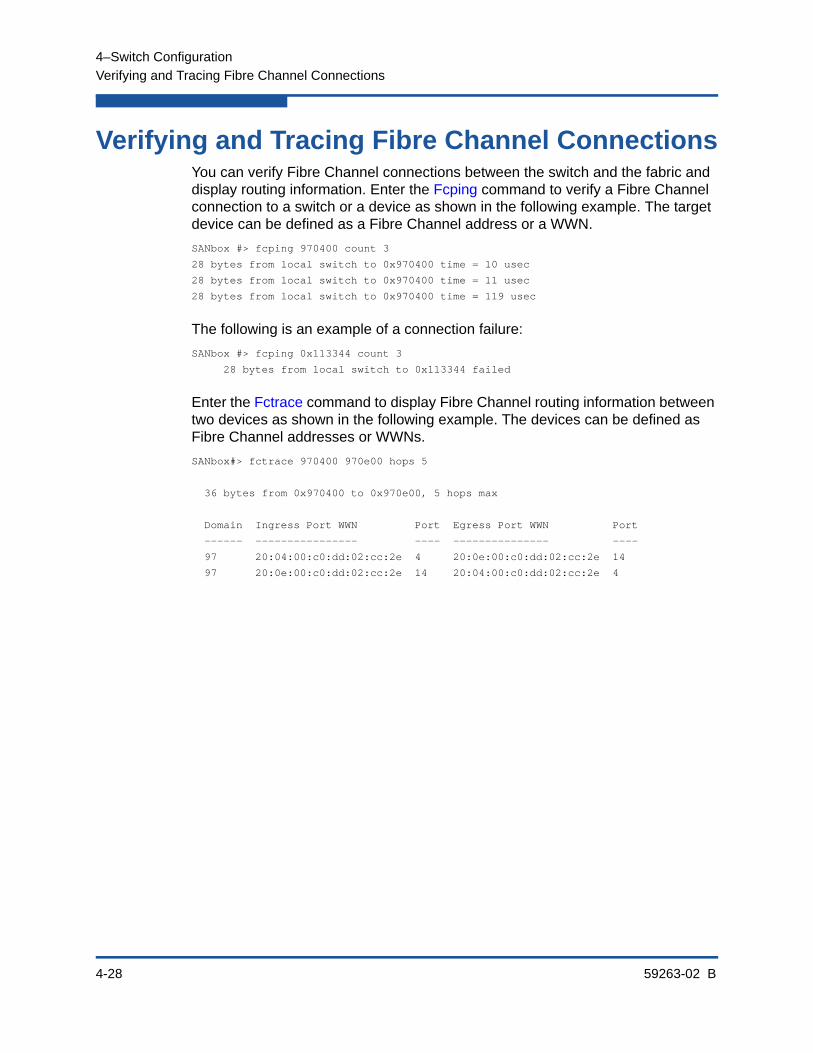
4–Switch Configuration
Verifying and Tracing Fibre Channel Connections
4-28 59263-02 B
Verifying and Tracing Fibre Channel ConnectionsYou can verify Fibre Channel connections between the switch and the fabric and display routing information. Enter the Fcping command to verify a Fibre Channel connection to a switch or a device as shown in the following example. The target device can be defined as a Fibre Channel address or a WWN.
SANbox #> fcping 970400 count 3
28 bytes from local switch to 0x970400 time = 10 usec
28 bytes from local switch to 0x970400 time = 11 usec
28 bytes from local switch to 0x970400 time = 119 usec
The following is an example of a connection failure:
SANbox #> fcping 0x113344 count 3
28 bytes from local switch to 0x113344 failed
Enter the Fctrace command to display Fibre Channel routing information between two devices as shown in the following example. The devices can be defined as Fibre Channel addresses or WWNs.
SANbox#> fctrace 970400 970e00 hops 5
36 bytes from 0x970400 to 0x970e00, 5 hops max
Domain Ingress Port WWN Port Egress Port WWN Port
------ ---------------- ---- --------------- ----
97 20:04:00:c0:dd:02:cc:2e 4 20:0e:00:c0:dd:02:cc:2e 14
97 20:0e:00:c0:dd:02:cc:2e 14 20:04:00:c0:dd:02:cc:2e 4

4–Switch Configuration
Managing Switch Feature Upgrades
59263-02 B 4-29
Managing Switch Feature UpgradesThe following features are available to upgrade your switch through the purchase and installation of a license key:
Enterprise Fabric Suite is a workstation-based Java® application that provides a graphical user interface for fabric management. This includes Performance View which graphs port performance. Enterprise Fabric Suite comes with a free 30-day trial license.
Port Activation enables additional Fibre Channel ports up to the 24-port maximum.
20Gb Activation upgrades the XPAK ports to 20Gbps.
Installing a feature license key is not disruptive, nor does it require a switch reset. To order a license key, contact your switch distributor or your authorized reseller.
Displaying Feature LicensesEnter the Feature Log command to display the license keys that are installed on your switch as shown in the following example:
SANbox #> feature log
Mfg Feature Log: ----------------
Switch Licensed for 8 ports
Customer Feature Log: ---------------------
1) day month date 19:39:24 year - Switch Licensed for 24 ports 1-LCVXOWUNOJBE6
Installing a Feature License KeyEnter the Feature Add command to install a license key on your switch as shown in the following example:
SANbox #> admin start
SANbox (admin) #> feature add 1-LCVXOWUNOJBE6
License upgrade to 24 ports
Do you want to continue with license upgrade procedure? (y/n): [n] y
Alarm Msg:[day mon date time year][A1005.0030][SM][Upgrading Licensed Ports to 24]
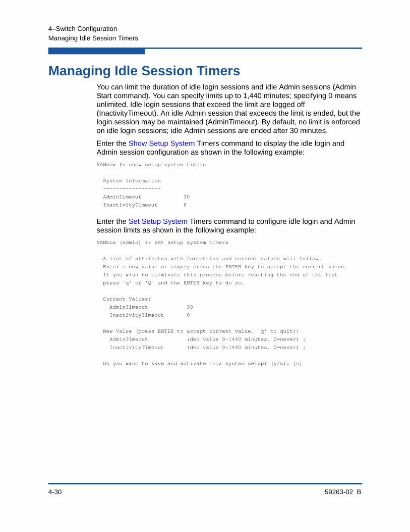
4–Switch Configuration
Managing Idle Session Timers
4-30 59263-02 B
Managing Idle Session TimersYou can limit the duration of idle login sessions and idle Admin sessions (Admin Start command). You can specify limits up to 1,440 minutes; specifying 0 means unlimited. Idle login sessions that exceed the limit are logged off (InactivityTimeout). An idle Admin session that exceeds the limit is ended, but the login session may be maintained (AdminTimeout). By default, no limit is enforced on idle login sessions; idle Admin sessions are ended after 30 minutes.
Enter the Show Setup System Timers command to display the idle login and Admin session configuration as shown in the following example:
SANbox #> show setup system timers
System Information
------------------
AdminTimeout 30
InactivityTimeout 0
Enter the Set Setup System Timers command to configure idle login and Admin session limits as shown in the following example:
SANbox (admin) #> set setup system timers
A list of attributes with formatting and current values will follow.
Enter a new value or simply press the ENTER key to accept the current value.
If you wish to terminate this process before reaching the end of the list
press 'q' or 'Q' and the ENTER key to do so.
Current Values:
AdminTimeout 30
InactivityTimeout 0
New Value (press ENTER to accept current value, 'q' to quit):
AdminTimeout (dec value 0-1440 minutes, 0=never) :
InactivityTimeout (dec value 0-1440 minutes, 0=never) :
Do you want to save and activate this system setup? (y/n): [n]
59263-02 B 5-1
5 Port Configuration
This section describes the following topics:
Displaying Port Information
Modifying Port Operating Characteristics
Configuring Transparent Routing
Port Binding
Resetting a Port
Configuring Port Threshold Alarms
Testing a Port
Displaying Extended Credit Status
Displaying Port InformationYou can display the following port information:
Port Configuration Parameters
Port Operational Information
Port Threshold Alarm Configuration Parameters
Port Performance

5–Port Configuration
Displaying Port Information
5-2 59263-02 B
Port Configuration ParametersEnter the Show Config Port command to display the port configuration parameters. These parameters determine the operational characteristics of the port. Refer to Table 13-21 for a description of these parameters.
SANbox #> show config port 0
Configuration Name: default
-----------------------------
Port Number: 0
------------
AdminState Offline
LinkSpeed Auto
PortType GL
SymbolicName Port0
ALFairness False
DeviceScanEnabled True
ForceOfflineRSCN False
ARB_FF False
InteropCredit 0
ExtCredit 0
FANEnabled True
AutoPerfTuning False
LCFEnabled False
MFSEnabled True
VIEnabled False
MSEnabled True
NoClose False
IOStreamGuard Disabled
PDISCPingEnable True
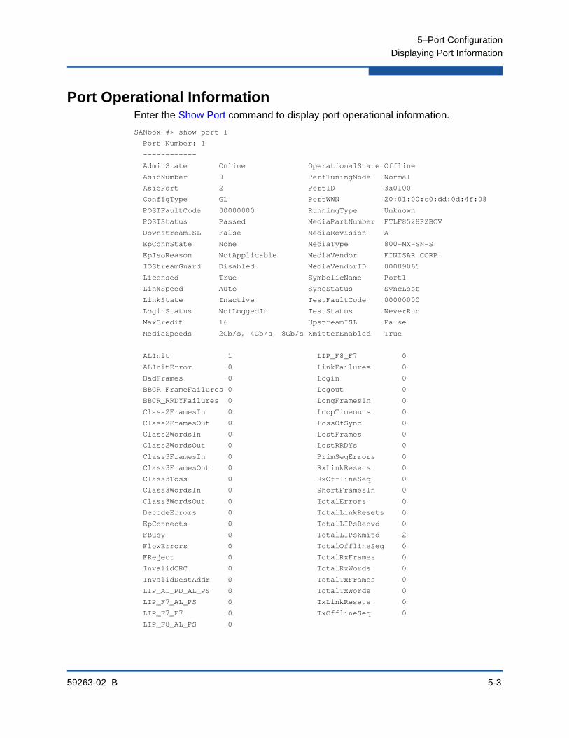
5–Port Configuration
Displaying Port Information
59263-02 B 5-3
Port Operational InformationEnter the Show Port command to display port operational information.
SANbox #> show port 1
Port Number: 1
------------
AdminState Online OperationalState Offline
AsicNumber 0 PerfTuningMode Normal
AsicPort 2 PortID 3a0100
ConfigType GL PortWWN 20:01:00:c0:dd:0d:4f:08
POSTFaultCode 00000000 RunningType Unknown
POSTStatus Passed MediaPartNumber FTLF8528P2BCV
DownstreamISL False MediaRevision A
EpConnState None MediaType 800-MX-SN-S
EpIsoReason NotApplicable MediaVendor FINISAR CORP.
IOStreamGuard Disabled MediaVendorID 00009065
Licensed True SymbolicName Port1
LinkSpeed Auto SyncStatus SyncLost
LinkState Inactive TestFaultCode 00000000
LoginStatus NotLoggedIn TestStatus NeverRun
MaxCredit 16 UpstreamISL False
MediaSpeeds 2Gb/s, 4Gb/s, 8Gb/s XmitterEnabled True
ALInit 1 LIP_F8_F7 0
ALInitError 0 LinkFailures 0
BadFrames 0 Login 0
BBCR_FrameFailures 0 Logout 0
BBCR_RRDYFailures 0 LongFramesIn 0
Class2FramesIn 0 LoopTimeouts 0
Class2FramesOut 0 LossOfSync 0
Class2WordsIn 0 LostFrames 0
Class2WordsOut 0 LostRRDYs 0
Class3FramesIn 0 PrimSeqErrors 0
Class3FramesOut 0 RxLinkResets 0
Class3Toss 0 RxOfflineSeq 0
Class3WordsIn 0 ShortFramesIn 0
Class3WordsOut 0 TotalErrors 0
DecodeErrors 0 TotalLinkResets 0
EpConnects 0 TotalLIPsRecvd 0
FBusy 0 TotalLIPsXmitd 2
FlowErrors 0 TotalOfflineSeq 0
FReject 0 TotalRxFrames 0
InvalidCRC 0 TotalRxWords 0
InvalidDestAddr 0 TotalTxFrames 0
LIP_AL_PD_AL_PS 0 TotalTxWords 0
LIP_F7_AL_PS 0 TxLinkResets 0
LIP_F7_F7 0 TxOfflineSeq 0
LIP_F8_AL_PS 0
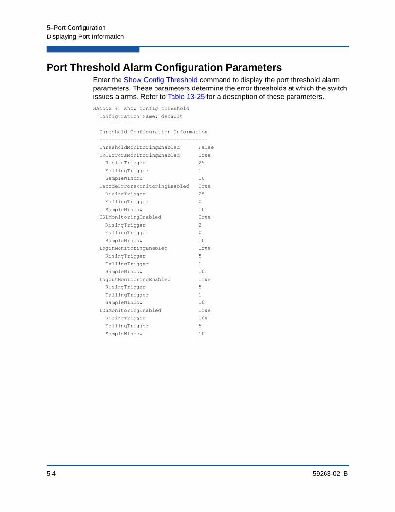
5–Port Configuration
Displaying Port Information
5-4 59263-02 B
Port Threshold Alarm Configuration ParametersEnter the Show Config Threshold command to display the port threshold alarm parameters. These parameters determine the error thresholds at which the switch issues alarms. Refer to Table 13-25 for a description of these parameters.
SANbox #> show config threshold
Configuration Name: default
------------
Threshold Configuration Information
-----------------------------------
ThresholdMonitoringEnabled False
CRCErrorsMonitoringEnabled True
RisingTrigger 25
FallingTrigger 1
SampleWindow 10
DecodeErrorsMonitoringEnabled True
RisingTrigger 25
FallingTrigger 0
SampleWindow 10
ISLMonitoringEnabled True
RisingTrigger 2
FallingTrigger 0
SampleWindow 10
LoginMonitoringEnabled True
RisingTrigger 5
FallingTrigger 1
SampleWindow 10
LogoutMonitoringEnabled True
RisingTrigger 5
FallingTrigger 1
SampleWindow 10
LOSMonitoringEnabled True
RisingTrigger 100
FallingTrigger 5
SampleWindow 10

5–Port Configuration
Displaying Port Information
59263-02 B 5-5
Port PerformanceEnter the Show Perf command to display port performance in terms of the volume of data transmitted, data received, or errors. You can display continuous live performance information for one or more ports, or an instantaneous summary. The following example displays an instantaneous summary in bytes and frames. Values are expressed in thousands (K) and millions (M) of bytes or frames per second.
SANbox #> show perf
Port Bytes/s Bytes/s Bytes/s Frames/s Frames/s Frames/s
Number (in) (out) (total) (in) (out) (total)
------ ------- ------- ------- -------- -------- --------
0 7K 136M 136M 245 68K 68K
1 58K 0 58K 1K 0 1K
2 0 0 0 0 0 0
3 0 0 0 0 0 0
4 0 0 0 0 0 0
5 0 0 0 0 0 0
6 0 7K 7K 0 245 245
7 136M 58K 136M 68K 1K 70K
8 7K 136M 136M 245 68K 68K
9 58K 0 58K 1K 0 1K
10 0 0 0 0 0 0
11 0 0 0 0 0 0
12 0 0 0 0 0 0
13 0 0 0 0 0 0
14 0 7K 7K 0 245 245
15 136M 58K 136M 68K 1K 70K
16 47M 23K 47M 23K 726 24K
17 0 0 0 0 0 0
18 23K 47M 47M 726 23K 24K
19 0 0 0 0 0 0
20 0 0 0 0 0 0
21 0 0 0 0 0 0
22 0 0 0 0 0 0
23 0 0 0 0 0 0
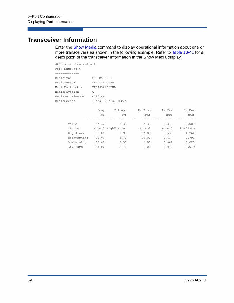
5–Port Configuration
Displaying Port Information
5-6 59263-02 B
Transceiver InformationEnter the Show Media command to display operational information about one or more transceivers as shown in the following example. Refer to Table 13-41 for a description of the transceiver information in the Show Media display.
SANbox #> show media 4
Port Number: 4
-------------
MediaType 400-M5-SN-I
MediaVendor FINISAR CORP.
MediaPartNumber FTRJ8524P2BNL
MediaRevision A
MediaSerialNumber P6G22RL
MediaSpeeds 1Gb/s, 2Gb/s, 4Gb/s
Temp Voltage Tx Bias Tx Pwr Rx Pwr
(C) (V) (mA) (mW) (mW)
----------- ----------- ------------ ----------- -----------
Value 37.32 3.33 7.30 0.373 0.000
Status Normal HighWarning Normal Normal LowAlarm
HighAlarm 95.00 3.90 17.00 0.637 1.264
HighWarning 90.00 3.70 14.00 0.637 0.791
LowWarning -20.00 2.90 2.00 0.082 0.028
LowAlarm -25.00 2.70 1.00 0.073 0.019

5–Port Configuration
Modifying Port Operating Characteristics
59263-02 B 5-7
Modifying Port Operating CharacteristicsYou can make permanent or temporary changes to port operating characteristics. You make permanent port configuration changes using the Set Config Port command. These changes are saved in the active configuration and are preserved across switch or port resets. The Set Port command makes temporary changes that apply until the next port or switch reset, or until you activate a configuration.
The following example permanently changes the port 1 administrative state:
SANbox #> admin start
SANbox (admin) #> config edit
SANbox (admin-config) #> set config port 1
A list of attributes with formatting and current values will follow.
Enter a new value or simply press the ENTER key to accept the current value.
If you wish to terminate this process before reaching the end of the list
press 'q' or 'Q' and the ENTER key to do so.
Configuring Port Number: 1
------------------------
AdminState (1=Online, 2=Offline, 3=Diagnostics, 4=Down) [Online] offline
LinkSpeed (1=Gb/s, 2=2Gb/s, 4=4Gb/s, 8=8Gb/s, A=Auto) [Auto ]
PortType (GL / G / F / FL / Donor) [GL ]
SymPortName (string, max=32 chars) [Port1 ]
ALFairness (True / False) [False ]
DeviceScanEnable (True / False) [True ]
ForceOfflineRSCN (True / False) [False ]
ARB_FF (True / False) [False ]
InteropCredit (decimal value, 0-255) [0 ]
FANEnable (True / False) [True ]
AutoPerfTuning (True / False) [False ]
LCFEnable (True / False) [False ]
MFSEnable (True / False) [False ]
VIEnable (True / False) [False ]
MSEnable (True / False) [True ]
NoClose (True / False) [False ]
IOStreamGuard (Enable / Disable / Auto) [Disable]
PDISCPingEnable (True / False) [True ]
Finished configuring attributes.
This configuration must be saved (see config save command) and
activated (see config activate command) before it can take effect.
NOTE:
8-Gbps SFPs do not support the 1-Gbps setting. Setting a port to 1-Gbps that has an 8-Gbps SFP will down the port.

5–Port Configuration
Configuring Transparent Routing
5-8 59263-02 B
To discard this configuration use the config cancel command.
SANbox (admin-config) #> config save
SANbox (admin-config) #> config activate
You can configure all ports based a specified source port using the Set Config Ports command. The following example configures ports 0–23 based on port 3.
SANbox #> admin start
SANbox (admin) config edit
SANbox (admin) #> set config ports 3
.
.
.
SANbox (admin-config)#> config save
SANbox (admin)#> config activate
SANbox (admin)#> admin end
The following example temporarily changes the port 1 administrative state to Down:
SANbox #> admin start
SANbox (admin) #> set port 1 state down
Configuring Transparent RoutingThe transparent routing feature provides inter-fabric routing to allow controlled and limited access between devices on a QLogic 5800V Series (local) fabric and devices on a remote fabric consisting of noncompliant switches made by other vendors. This type of inter-fabric connection uses the Fibre Channel industry N-Port ID Virtualization (NPIV), and makes local and remote devices accessible to each other while maintaining the local and remote fabrics as separate fabrics.
You can configure transparent routing using the CLI, QuickTools, and Enterprise Fabric Suite. However, only QuickTools and Enterprise Fabric Suite validate your entries, manage the zone mapping for the local fabric, and create a list of zoning commands that can be run in a script on a Brocade® or Cisco® SAN switch. For more information, see the QLogic 5800V Series QuickTools Switch Management User’s Guide or the QLogic 5800V Series Enterprise Fabric Suite User’s Guide.
You can connect multiple QLogic 5800V Series Switches to one or more remote fabrics using multiple TR_Ports. Local and remote devices are identified by their respective port worldwide names. Consider the following mapping rules:
A TR_Port can support a maximum of 32 local device/remote device mappings.
A specific local device can be mapped to devices on only one remote fabric. Local devices on the same QLogic 5800V Series Switch can each be mapped to different remote fabrics.
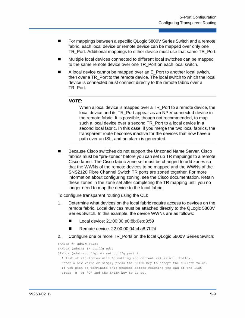
5–Port Configuration
Configuring Transparent Routing
59263-02 B 5-9
For mappings between a specific QLogic 5800V Series Switch and a remote fabric, each local device or remote device can be mapped over only one TR_Port. Additional mappings to either device must use that same TR_Port.
Multiple local devices connected to different local switches can be mapped to the same remote device over one TR_Port on each local switch.
A local device cannot be mapped over an E_Port to another local switch, then over a TR_Port to the remote device. The local switch to which the local device is connected must connect directly to the remote fabric over a TR_Port.
Because Cisco switches do not support the Unzoned Name Server, Cisco fabrics must be “pre-zoned” before you can set up TR mappings to a remote Cisco fabric. The Cisco fabric zone set must be changed to add zones so that the WWNs of the remote devices to be mapped and the WWNs of the SNS2120 Fibre Channel Switch TR ports are zoned together. For more information about configuring zoning, see the Cisco documentation. Retain these zones in the zone set after completing the TR mapping until you no longer need to map the device to the local fabric.
To configure transparent routing using the CLI:
1. Determine what devices on the local fabric require access to devices on the remote fabric. Local devices must be attached directly to the QLogic 5800V Series Switch. In this example, the device WWNs are as follows:
Local device: 21:00:00:e0:8b:0e:d3:59
Remote device: 22:00:00:04:cf:a8:7f:2d
2. Configure one or more TR_Ports on the local QLogic 5800V Series Switch:
SANbox #> admin start
SANbox (admin) #> config edit
SANbox (admin-config) #> set config port 1
A list of attributes with formatting and current values will follow.
Enter a new value or simply press the ENTER key to accept the current value.
If you wish to terminate this process before reaching the end of the list
press 'q' or 'Q' and the ENTER key to do so.
NOTE:
When a local device is mapped over a TR_Port to a remote device, the local device and its TR_Port appear as an NPIV connected device in the remote fabric. It is possible, though not recommended, to map such a local device over a second TR_Port to a local device in a second local fabric. In this case, if you merge the two local fabrics, the transparent route becomes inactive for the devices that now have a path over an ISL, and an alarm is generated.

5–Port Configuration
Configuring Transparent Routing
5-10 59263-02 B
Configuring Port Number: 1
------------------------
AdminState (1=Online, 2=Offline, 3=Diagnostics, 4=Down) [Online]
LinkSpeed (1=1Gb/s, 2=2Gb/s, 4=4Gb/s, 8=8Gb/s, A=Auto) [Auto ]
PortType (GL, G, F, FL, TR) [GL ] TR
SymPortName (string, max=32 chars) [Port1 ]
.
.
.
Finished configuring attributes.
This configuration must be saved (see config save command) and
activated (see config activate command) before it can take effect.
To discard this configuration use the config cancel command.
SANbox (admin-config) #> config save
SANbox (admin-config) #> config activate
3. Connect the TR_Port to the remote fabric. For remote Brocade and Cisco fabrics, the switch to which the TR_Port is connected must support NPIV, and for the Brocade switch, the interoperability mode must be disabled (InteropMode=0). Other switches in the remote fabric need not support NPIV, but the interoperability mode on all Brocade switches must be disabled.
4. Map local devices to remote devices by creating an inter-fabric zone. The inter-fabric zone contains the port WWNs of the local device, the remote device, and the TR_Port. The name of the inter-fabric zone begins with IFZ followed by the lowest device port WWN followed by the remaining port WWN, all uppercase, separated by underscores (_).
NOTE:
Be sure to configure the TR_Port before connecting the remote fabric to the QLogic 5800V Series Switch. If the remote fabric is connected to a port on theQLogic 5800V Series Switch that is not a TR_Port, the two fabrics may establish an E_Port connection and the local and remote fabrics may merge. This mixed fabric is not a supported configuration. If the port type is changed to TR_Port after connecting the remote fabric, a port reset may be required to completely establish the TR connection.

5–Port Configuration
Port Binding
59263-02 B 5-11
a. Create the inter-fabric zone:
SANbox #> admin start
SANbox (admin) #> zoning edit
SANbox (admin-zoning) #>zone create IFZ_210000E08B0ED359_22000004CFA87F2D
b. Add the device and TR_Port WWNs to the inter-fabric zone:
SANbox (admin-zoning) #>zone add IFZ_210000E08B0ED359_22000004CFA87F2D 21:00:00:e0:8b:0e:d3:59 22:00:00:04:cf:a8:7f:2d 20:01:00:c0:dd:0d:53:a5
c. Add the new zone to the active zone set, save the zone set, and activate it.
SANbox (admin-zoning) #>zoneset add zoneset_alpha IFZ_210000E08B0ED359_22000004CFA87F2D
SANbox (admin-zoning) #> zoning save
The changes have been saved; however, they must be activated before they can take effect -- see Zoneset Activate command.
SANbox (admin) #> zoneset activate zoneset_alpha
5. Apply the same inter-fabric zone that was created on the local fabric to the active zoning on the remote Brocade or Cisco fabric. When modifications to the active zoning on both fabrics are complete, the transparent routing connection becomes active, and local devices will discover remote devices.
To remove a transparent route, in addition to removing the local inter-fabric zone, you must also remove the corresponding remote inter-fabric zone.
Port BindingPort binding establishes up to 32 switches or devices that are permitted to log in to a particular switch port. Switches or devices that are not among the 32 are refused access to the port. Enter the Show Config Security Portbinding command to display the port binding configuration for all ports as shown in the following example.
SANbox #> show config security portbinding
Configuration Name: default
-------------------
Port Binding Status WWN
---- -------------- ---
0 True 10:20:30:40:50:60:70:80

5–Port Configuration
Port Binding
5-12 59263-02 B
1 True 10:20:30:40:50:60:70:80
2 False No port binding entries found.
3 True 10:20:30:40:50:60:70:80
4 True 10:20:30:40:50:60:70:80
5 False No port binding entries found.
6 True 10:20:30:40:50:60:70:81
7 False No port binding entries found.
8 True 10:20:30:40:50:60:70:80
9 False No port binding entries found.
10 False No port binding entries found.
11 False No port binding entries found.
12 False No port binding entries found.
13 False No port binding entries found.
14 False No port binding entries found.
15 False No port binding entries found.
16 False No port binding entries found.
17 False No port binding entries found.
18 False No port binding entries found.
19 False No port binding entries found.
20 False No port binding entries found.
21 False No port binding entries found.
22 False No port binding entries found.
23 False No port binding entries found.
Enter the Set Config Security Portbinding command to enable port binding for the selected port and to specify the world wide names of the authorized ports/devices. The following example enables port binding on port 1 and specifies two device world wide names.
SANbox #> admin start
SANbox (admin) #> config edit
SANbox (admin-config) #> set config security port 1
A list of attributes with formatting and current values will follow.
Enter a new value or simply press the ENTER key to accept the current value.
If you wish to terminate this process before reaching the end of the list
press 'q' or 'Q' and the ENTER key to do so.
PortBindingEnabled (True / False)[False] true
WWN (N=None / WWN)[None ] 10:00:00:c0:dd:00:b9:f9
WWN (N=None / WWN)[None ] 10:00:00:c0:dd:00:b9:f8
WWN (N=None / WWN)[None ] n
Finished configuring attributes.
This configuration must be saved (see config save command) and
activated (see config activate command) before it can take effect.
To discard this configuration use the config cancel command.

5–Port Configuration
Resetting a Port
59263-02 B 5-13
Resetting a PortEnter the Reset Port command to reinitialize one or more ports and to discard any temporary changes that have been made to the administrative state or link speed. The following example reinitializes port 1:
SANbox #> reset port 1
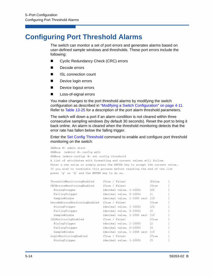
5–Port Configuration
Configuring Port Threshold Alarms
5-14 59263-02 B
Configuring Port Threshold AlarmsThe switch can monitor a set of port errors and generates alarms based on user-defined sample windows and thresholds. These port errors include the following:
Cyclic Redundancy Check (CRC) errors
Decode errors
ISL connection count
Device login errors
Device logout errors
Loss-of-signal errors
You make changes to the port threshold alarms by modifying the switch configuration as described in “Modifying a Switch Configuration” on page 4-11. Refer to Table 13-25 for a description of the port alarm threshold parameters.
The switch will down a port if an alarm condition is not cleared within three consecutive sampling windows (by default 30 seconds). Reset the port to bring it back online. An alarm is cleared when the threshold monitoring detects that the error rate has fallen below the falling trigger.
Enter the Set Config Threshold command to enable and configure port threshold monitoring on the switch:
SANbox #> admin start
SANbox (admin) #> config edit
SANbox (admin-config) #> set config threshold
A list of attributes with formatting and current values will follow.
Enter a new value or simply press the ENTER key to accept the current value.
If you wish to terminate this process before reaching the end of the list
press 'q' or 'Q' and the ENTER key to do so.
ThresholdMonitoringEnabled (True / False) [False ]
CRCErrorsMonitoringEnabled (True / False) [True ]
RisingTrigger (decimal value, 1-1000) [25 ]
FallingTrigger (decimal value, 0-1000) [1 ]
SampleWindow (decimal value, 1-1000 sec) [10 ]
DecodeErrorsMonitoringEnabled (True / False) [True ]
RisingTrigger (decimal value, 1-1000) [25 ]
FallingTrigger (decimal value, 0-1000) [0 ]
SampleWindow (decimal value, 1-1000 sec) [10 ]
ISLMonitoringEnabled (True / False) [True ]
RisingTrigger (decimal value, 1-1000) [2 ]
FallingTrigger (decimal value, 0-1000) [0 ]
SampleWindow (decimal value, 1-1000 sec) [10 ]
LoginMonitoringEnabled (True / False) [True ]
RisingTrigger (decimal value, 1-1000) [5 ]
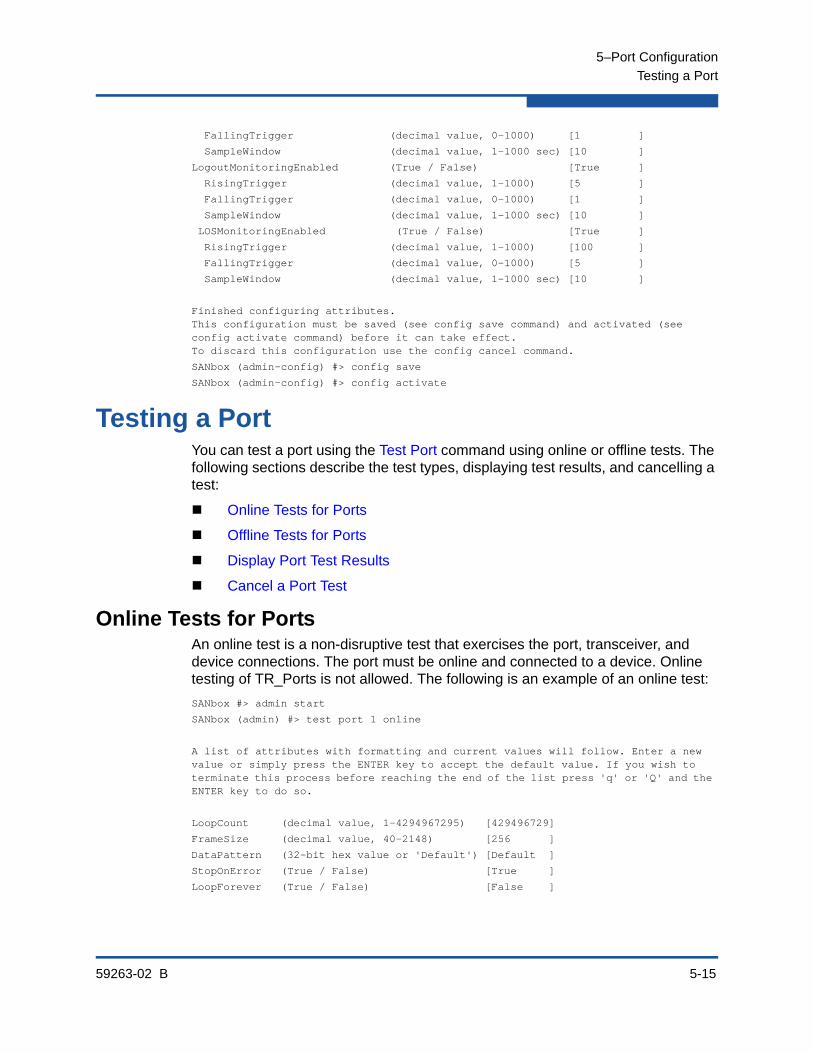
5–Port Configuration
Testing a Port
59263-02 B 5-15
FallingTrigger (decimal value, 0-1000) [1 ]
SampleWindow (decimal value, 1-1000 sec) [10 ]
LogoutMonitoringEnabled (True / False) [True ]
RisingTrigger (decimal value, 1-1000) [5 ]
FallingTrigger (decimal value, 0-1000) [1 ]
SampleWindow (decimal value, 1-1000 sec) [10 ]
LOSMonitoringEnabled (True / False) [True ]
RisingTrigger (decimal value, 1-1000) [100 ]
FallingTrigger (decimal value, 0-1000) [5 ]
SampleWindow (decimal value, 1-1000 sec) [10 ]
Finished configuring attributes.This configuration must be saved (see config save command) and activated (see config activate command) before it can take effect.To discard this configuration use the config cancel command.
SANbox (admin-config) #> config save
SANbox (admin-config) #> config activate
Testing a PortYou can test a port using the Test Port command using online or offline tests. The following sections describe the test types, displaying test results, and cancelling a test:
Online Tests for Ports
Offline Tests for Ports
Display Port Test Results
Cancel a Port Test
Online Tests for PortsAn online test is a non-disruptive test that exercises the port, transceiver, and device connections. The port must be online and connected to a device. Online testing of TR_Ports is not allowed. The following is an example of an online test:
SANbox #> admin start
SANbox (admin) #> test port 1 online
A list of attributes with formatting and current values will follow. Enter a new value or simply press the ENTER key to accept the default value. If you wish to terminate this process before reaching the end of the list press 'q' or 'Q' and the ENTER key to do so.
LoopCount (decimal value, 1-4294967295) [429496729]
FrameSize (decimal value, 40-2148) [256 ]
DataPattern (32-bit hex value or 'Default') [Default ]
StopOnError (True / False) [True ]
LoopForever (True / False) [False ]

5–Port Configuration
Testing a Port
5-16 59263-02 B
Do you want to start the test? (y/n) [n] y
The test has been started.
A notification with the test result(s) will appear
on the screen when the test has completed.
SANbox (admin) #>
Test for port 1 Passed.
Offline Tests for PortsAn offline test is a disruptive test that exercises the port connections. You must place the port in the diagnostics state using the Set Port command before starting the test. There are two types of offline test: internal loopback and external loopback.
An internal loopback test exercises the internal port connections.
An external loopback test exercises the port and its transceiver. A transceiver with a loopback plug is required for the port.
The following example performs an offline test:
SANbox #> admin start
SANbox (admin) #> set port 1 state diagnostics
SANbox (admin) #> test port 1 offline internal
A list of attributes with formatting and current values will follow. Enter a new value or simply press the ENTER key to accept the default value. If you wish to terminate this process before reaching the end of the list press 'q' or 'Q' and the ENTER key to do so.
LoopCount (decimal value, 1-4294967295) [429496729]
FrameSize (decimal value, 40-2148) [256 ]
DataPattern (32-bit hex value or 'Default') [Default ]
StopOnError (True / False) [True ]
LoopForever (True / False) [False ]
Do you want to start the test? (y/n) [n] y
The test has been started.
A notification with the test result(s) will appear
on the screen when the test has completed.
SANbox (admin) #>
Test for port 1 Passed.
When the test is complete, remember to place the port back online.
SANbox (admin) #> set port 1 state online
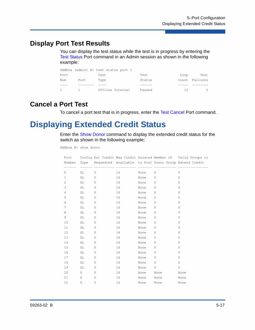
5–Port Configuration
Displaying Extended Credit Status
59263-02 B 5-17
Display Port Test ResultsYou can display the test status while the test is in progress by entering the Test Status Port command in an Admin session as shown in the following example:
SANbox (admin) #> test status port 1
Port Test Test Loop Test
Num Port Type Status Count Failures
---- -------- ---- ------ ----- --------
1 1 Offline Internal Passed 12 0
Cancel a Port Test To cancel a port test that is in progress, enter the Test Cancel Port command.
Displaying Extended Credit StatusEnter the Show Donor command to display the extended credit status for the switch as shown in the following example:
SANbox #> show donor
Port Config Ext Credit Max Credit Donated Member of Valid Groups to
Number Type Requested Available to Port Donor Group Extend Credit
------ ------ ---------- ---------- ------- ----------- ---------------
0 GL 0 16 None 0 0
1 GL 0 16 None 0 0
2 GL 0 16 None 0 0
3 GL 0 16 None 0 0
4 GL 0 16 None 0 0
5 GL 0 16 None 0 0
6 GL 0 16 None 0 0
7 GL 0 16 None 0 0
8 GL 0 16 None 0 0
9 GL 0 16 None 0 0
10 GL 0 16 None 0 0
11 GL 0 16 None 0 0
12 GL 0 16 None 0 0
13 GL 0 16 None 0 0
14 GL 0 16 None 0 0
15 GL 0 16 None 0 0
16 GL 0 16 None 0 0
17 GL 0 16 None 0 0
18 GL 0 16 None 0 0
19 GL 0 16 None 0 0
20 G 0 16 None None None
21 G 0 16 None None None
22 G 0 16 None None None
5–Port Configuration
Displaying Extended Credit Status
5-18 59263-02 B
23 G 0 16 None None None
Donor Group Credit Pool
----------- -----------
0 0
59263-02 B 6-1
6 Zoning Configuration
This section describes the following tasks:
Displaying Zoning Database Information
Configuring the Zoning Database
Modifying the Zoning Database
Saving the Active and Merged Zone Sets
Resetting the Zoning Database
Managing Zone Sets
Managing Zones
Managing Aliases
Consider device access needs within the fabric. Access is controlled by the use of zoning. Some zoning strategies include the following:
Separate devices by operating system.
Separate devices that have no need to communicate with other devices in the fabric or have classified data.
Separate devices into department, administrative, or other functional group.
Reserve a path and its bandwidth from one port to another.
A zone is a named group of ports or devices. Members of the same zone can communicate with each other and transmit outside the zone, but cannot receive inbound traffic from outside the zone.
Zoning divides the fabric for purposes of controlling discovery and inbound traffic. Zoning is hardware-enforced only when a port/device is a member of no more than eight zones whose combined membership does not exceed 64. If this condition is not satisfied, that port behaves as a soft zone member. You can assign ports/devices to a zone individually or as a group by creating an alias.
A zone can be a component of more than one zone set. Several zone sets can be defined for a fabric, but only one zone set can be active at one time. The active zone set determines the current fabric zoning.

6–Zoning Configuration
Displaying Zoning Database Information
6-2 59263-02 B
Displaying Zoning Database InformationA switch maintains three zoning databases:
Non-volatile–This zoning database is permanent and contains all zone sets, zones, and aliases that you create and save on a switch. The zone sets in the non-volatile zoning database are known as configured zone sets.
Volatile–This zoning database is temporary. This means it is not retained across switch resets. The volatile zoning database can be the working copy of a zone set being edited or the active zone set received from another switch. In the latter case, this is also known as the merged zone set.
Active–This zoning database is the active zone set.
You can display the following information about the zoning database:
Configured Zone Set Information
Active Zone Set Information
Merged Zone Set Information
Edited Zone Set Information
Zone Set Membership Information
Orphan Zone Information
Alias and Alias Membership Information
Zoning Modification History
Zoning Database Limits
Configured Zone Set InformationThe Zoneset List and the Zoning List commands display information about the all zone sets in the non-volatile zoning database. Enter the Zoneset List command to display a list of the zone sets as shown in the following example:
SANbox #> zoneset list
Current List of ZoneSets
------------------------
alpha
beta
Enter the Zoning List command to display all zone sets, zones, and zone members in the active zone set and configured zone sets as shown in the following example. Merged and edited zone sets are displayed if they exist.
SANbox #> zoning list
Active (enforced) ZoneSet Information
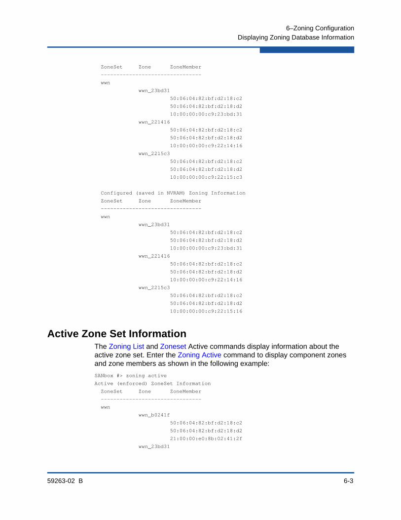
6–Zoning Configuration
Displaying Zoning Database Information
59263-02 B 6-3
ZoneSet Zone ZoneMember
--------------------------------
wwn
wwn_23bd31
50:06:04:82:bf:d2:18:c2
50:06:04:82:bf:d2:18:d2
10:00:00:00:c9:23:bd:31
wwn_221416
50:06:04:82:bf:d2:18:c2
50:06:04:82:bf:d2:18:d2
10:00:00:00:c9:22:14:16
wwn_2215c3
50:06:04:82:bf:d2:18:c2
50:06:04:82:bf:d2:18:d2
10:00:00:00:c9:22:15:c3
Configured (saved in NVRAM) Zoning Information
ZoneSet Zone ZoneMember
--------------------------------
wwn
wwn_23bd31
50:06:04:82:bf:d2:18:c2
50:06:04:82:bf:d2:18:d2
10:00:00:00:c9:23:bd:31
wwn_221416
50:06:04:82:bf:d2:18:c2
50:06:04:82:bf:d2:18:d2
10:00:00:00:c9:22:14:16
wwn_2215c3
50:06:04:82:bf:d2:18:c2
50:06:04:82:bf:d2:18:d2
10:00:00:00:c9:22:15:16
Active Zone Set InformationThe Zoning List and Zoneset Active commands display information about the active zone set. Enter the Zoning Active command to display component zones and zone members as shown in the following example:
SANbox #> zoning active
Active (enforced) ZoneSet Information
ZoneSet Zone ZoneMember
--------------------------------
wwn
wwn_b0241f
50:06:04:82:bf:d2:18:c2
50:06:04:82:bf:d2:18:d2
21:00:00:e0:8b:02:41:2f
wwn_23bd31
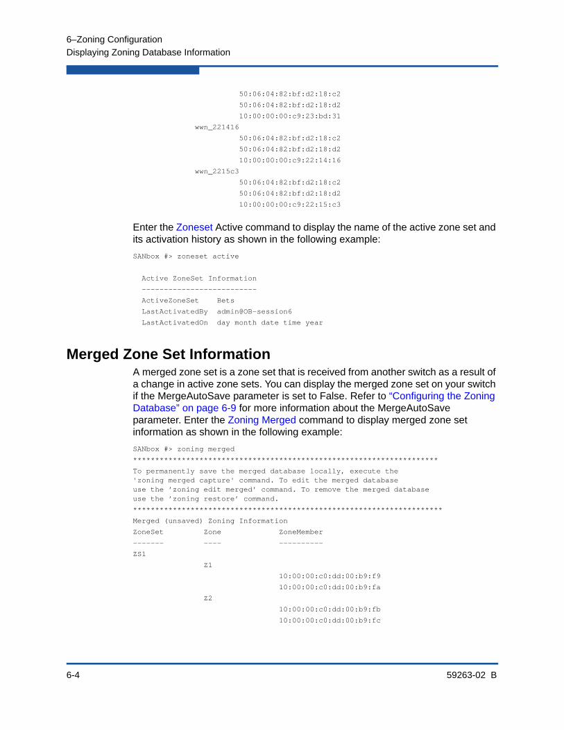
6–Zoning Configuration
Displaying Zoning Database Information
6-4 59263-02 B
50:06:04:82:bf:d2:18:c2
50:06:04:82:bf:d2:18:d2
10:00:00:00:c9:23:bd:31
wwn_221416
50:06:04:82:bf:d2:18:c2
50:06:04:82:bf:d2:18:d2
10:00:00:00:c9:22:14:16
wwn_2215c3
50:06:04:82:bf:d2:18:c2
50:06:04:82:bf:d2:18:d2
10:00:00:00:c9:22:15:c3
Enter the Zoneset Active command to display the name of the active zone set and its activation history as shown in the following example:
SANbox #> zoneset active
Active ZoneSet Information
--------------------------
ActiveZoneSet Bets
LastActivatedBy admin@OB-session6
LastActivatedOn day month date time year
Merged Zone Set InformationA merged zone set is a zone set that is received from another switch as a result of a change in active zone sets. You can display the merged zone set on your switch if the MergeAutoSave parameter is set to False. Refer to “Configuring the Zoning Database” on page 6-9 for more information about the MergeAutoSave parameter. Enter the Zoning Merged command to display merged zone set information as shown in the following example:
SANbox #> zoning merged
*********************************************************************
To permanently save the merged database locally, execute the'zoning merged capture' command. To edit the merged databaseuse the ’zoning edit merged’ command. To remove the merged databaseuse the ’zoning restore’ command.
**********************************************************************
Merged (unsaved) Zoning Information
ZoneSet Zone ZoneMember
------- ---- ----------
ZS1
Z1
10:00:00:c0:dd:00:b9:f9
10:00:00:c0:dd:00:b9:fa
Z2
10:00:00:c0:dd:00:b9:fb
10:00:00:c0:dd:00:b9:fc

6–Zoning Configuration
Displaying Zoning Database Information
59263-02 B 6-5
Edited Zone Set InformationThe edited zone set is a zone set that you were modifying when a change in active zone set or a fabric merge occurred. Enter the Zoning Edited command to display the unsaved edited zone set information as shown in the following example:
SANbox (admin-zoning) #> zoning edited
Edited (unsaved) Zoning Information
ZoneSet Zone ZoneMember
------- ---- ----------
ZS1
Z1
10:00:00:c0:dd:00:b9:f9
10:00:00:c0:dd:00:b9:fa
Zone Set Membership InformationThe Zoneset Zones, Zone List, and Zone Zonesets commands display zone set membership information. Enter the Zoneset Zones command to display the member zones for a specified zone set as shown in the following example:
SANbox #> zoneset zones ssss
Current List of Zones for ZoneSet: ssss
----------------------------------
zone1
zone2
zone3
Enter the Zone List command to display the zones and the zone sets to which they belong as shown in the following example:
SANbox #> zone list
Zone ZoneSet
---- -------
wwn_b0241f
zone_set_1
wwn_23bd31
zone_set_1
wwn_221416
zone_set_2
wwn_2215c3
zone_set_2
wwn_0160ed
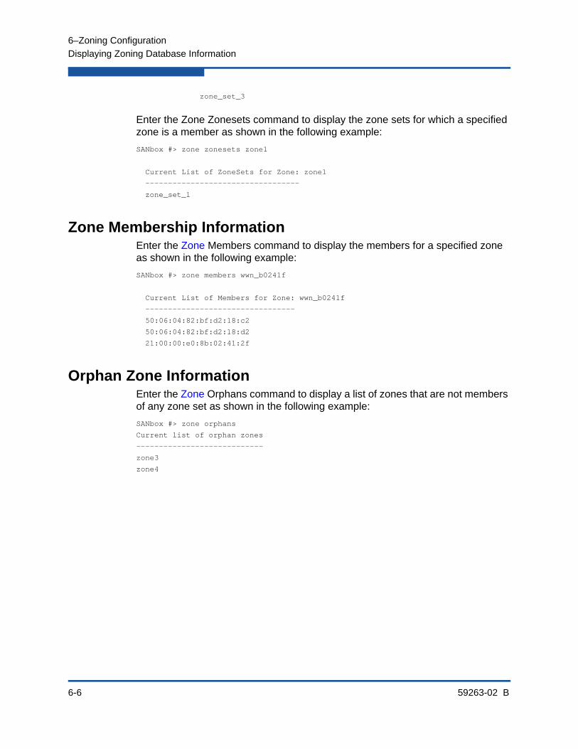
6–Zoning Configuration
Displaying Zoning Database Information
6-6 59263-02 B
zone_set_3
Enter the Zone Zonesets command to display the zone sets for which a specified zone is a member as shown in the following example:
SANbox #> zone zonesets zone1
Current List of ZoneSets for Zone: zone1
----------------------------------
zone_set_1
Zone Membership InformationEnter the Zone Members command to display the members for a specified zone as shown in the following example:
SANbox #> zone members wwn_b0241f
Current List of Members for Zone: wwn_b0241f
---------------------------------
50:06:04:82:bf:d2:18:c2
50:06:04:82:bf:d2:18:d2
21:00:00:e0:8b:02:41:2f
Orphan Zone InformationEnter the Zone Orphans command to display a list of zones that are not members of any zone set as shown in the following example:
SANbox #> zone orphans
Current list of orphan zones
----------------------------
zone3
zone4
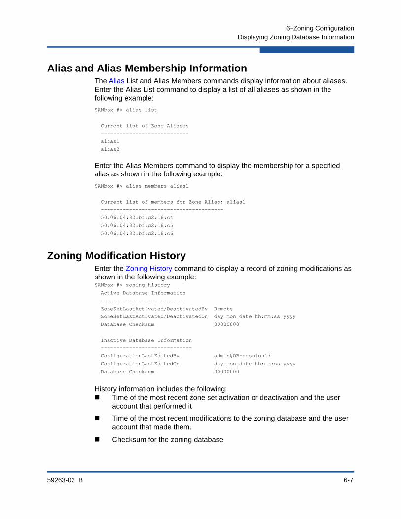
6–Zoning Configuration
Displaying Zoning Database Information
59263-02 B 6-7
Alias and Alias Membership InformationThe Alias List and Alias Members commands display information about aliases. Enter the Alias List command to display a list of all aliases as shown in the following example:
SANbox #> alias list
Current list of Zone Aliases
----------------------------
alias1
alias2
Enter the Alias Members command to display the membership for a specified alias as shown in the following example:
SANbox #> alias members alias1
Current list of members for Zone Alias: alias1
---------------------------------------
50:06:04:82:bf:d2:18:c4
50:06:04:82:bf:d2:18:c5
50:06:04:82:bf:d2:18:c6
Zoning Modification HistoryEnter the Zoning History command to display a record of zoning modifications as shown in the following example:SANbox #> zoning history
Active Database Information
---------------------------
ZoneSetLastActivated/DeactivatedBy Remote
ZoneSetLastActivated/DeactivatedOn day mon date hh:mm:ss yyyy
Database Checksum 00000000
Inactive Database Information
-----------------------------
ConfigurationLastEditedBy admin@OB-session17
ConfigurationLastEditedOn day mon date hh:mm:ss yyyy
Database Checksum 00000000
History information includes the following: Time of the most recent zone set activation or deactivation and the user
account that performed it
Time of the most recent modifications to the zoning database and the user account that made them.
Checksum for the zoning database
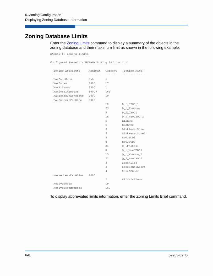
6–Zoning Configuration
Displaying Zoning Database Information
6-8 59263-02 B
Zoning Database LimitsEnter the Zoning Limits command to display a summary of the objects in the zoning database and their maximum limit as shown in the following example:
SANbox #> zoning limits
Configured (saved in NVRAM) Zoning Information
Zoning Attribute Maximum Current [Zoning Name]
---------------- ------- ------- -------------
MaxZoneSets 256 6
MaxZones 2000 17
MaxAliases 2500 1
MaxTotalMembers 10000 166
MaxZonesInZoneSets 2000 19
MaxMembersPerZone 2000
10 D_1_JBOD_1
23 D_1_Photons
9 D_2_JBOD1
16 D_2_NewJBOD_2
5 E1JBOD1
5 E2JBOD2
3 LinkResetZone
3 LinkResetZone2
8 NewJBOD1
8 NewJBOD2
24 Q_1Photon1
8 Q_1_NewJBOD1
13 Q_1_Photon_1
21 Q_2_NewJBOD2
3 ZoneAlias
3 ZoneDomainPort
4 ZoneFCAddr
MaxMembersPerAlias 2000
2 AliasInAZone
ActiveZones 19
ActiveZoneMembers 160
To display abbreviated limits information, enter the Zoning Limits Brief command.

6–Zoning Configuration
Configuring the Zoning Database
59263-02 B 6-9
Configuring the Zoning DatabaseYou can configure how the zoning database is applied to the switch and exchanged with the fabric through the zoning configuration parameters. The following zoning configuration parameters are available through the Set Config Zoning command. Refer to Table 13-26 for more information about the zoning configuration parameters.
MergeAutoSave–This parameter enables or disables the automatic saving of a new active zone set to the switch non-volatile zoning database.
DefaultZone–This parameter allows or denies communication among ports/devices that are not defined in the active zone set.
DiscardInactive–This parameter enables or disables the discarding of all zone sets except the active zone set.
If MergeAutoSave is False on a switch, and a new zone set is activated elsewhere in the fabric or a fabric merge occurs, you can choose how to dispose of the merged zone set:
Enter the Zoning Merged command to display merged zone set.
Enter the Zoning Edit Merged command to edit the merged zone set.
Enter the Zoning Merged Capture command to save the merged zone set to the non-volatile zoning database.
Enter the Zoning Restore command to discard the merged zone set.
If you are editing the configured zone set that corresponds to the active zone set, and a zone set merge occurs, you have the same options plus you can enter the Zoning Edited command to display the edited zoning database.
To restore the zoning configuration to its factory values, enter the Reset Config or Reset Factory commands. Notice however, these commands restore other aspects of the switch configuration also.

6–Zoning Configuration
Configuring the Zoning Database
6-10 59263-02 B
To modify the zoning configuration, you must open an Admin session with the Admin Start command. An Admin session prevents other accounts from making changes at the same time through Telnet, QuickTools, Enterprise Fabric Suite, or another management application. You must also open a Config Edit session with the Config Edit command and indicate which configuration you want to modify. If you do not specify a configuration name, the active configuration is assumed.
The Config Edit session provides access to the Set Config Zoning command as shown in the following example:
SANbox #> admin start
SANbox (admin) #> config edit
The config named default is being edited.
SANbox (admin-config) #> set config zoning
A list of attributes with formatting and current values will follow.
Enter a new value or simply press the ENTER key to accept the current value.
If you wish to terminate this process before reaching the end of the list press 'q' or 'Q' and the ENTER key to do so.
MergeAutoSave (True / False) [True ]
DefaultZone (Allow / Deny) [Allow ]
DiscardInactive (True / False) [False]
Finished configuring attributes.
This configuration must be saved (see config save command) and
activated (see config activate command) before it can take effect.
To discard this configuration use the config cancel command.
SANbox (admin-config)#> config save
SANbox (admin)#> config activate
SANbox (admin)#> admin end

6–Zoning Configuration
Modifying the Zoning Database
59263-02 B 6-11
Modifying the Zoning DatabaseTo modify the non-volatile zoning database, you must open an Admin session with the Admin Start command. An Admin session prevents other accounts from making changes at the same time through Telnet, Enterprise Fabric Suite, or another management application. You must also open a Zoning Edit session with the Zoning Edit Configured command. To modify the temporary merged zone set (if one exists), enter the Zoning Edit Merged command. The Zoning Edit session provides access to the Zoneset, Zone, Alias, and Zoning commands with which you make modifications to the zoning database.
SANbox #> admin start
SANbox (admin) #> zoning edit
SANbox (admin-zoning)#> zoneset . . .
SANbox (admin-zoning)#> zone . . .
SANbox (admin-zoning)#> alias . . .
SANbox (admin-zoning)#> zoning . . .
When you are finished making changes, enter the Zoning Save command to save the changes and close the Zoning Edit session.
SANbox (admin-zoning)#> zoning save
To close the Zoning Edit session without saving changes, enter the Zoning Cancel command.
SANbox (admin-zoning)#> zoning cancel
Changes to the active zone set do not take effect until you activate it with the Zoneset Activate command. The active zone set is propagated throughout the fabric.
SANbox (admin)#> zoneset activate zoneset_1
SANbox (admin)#> admin end
The Admin End command releases the Admin session for other administrators when you are done making changes to the switch.
To remove all zoning database objects (aliases, zones, and zone sets) and restore the zoning database to its factory state, enter the Reset Zoning command as shown in the following example:
SANbox (admin) #> reset zoning

6–Zoning Configuration
Saving the Active and Merged Zone Sets
6-12 59263-02 B
Saving the Active and Merged Zone SetsYou can save the active zone set and merged zone set to the non-volatile zoning database. Enter the Zoning Active Capture to save the active zone set as shown in the following example:
SANbox (admin) #> zoning active capture
This command will overwrite the configured zoning database in NVRAM.
Please confirm (y/n): [n] y
The active zoning database has been saved.
Enter the Zoning Merged Capture to the save the merged zone set as shown in the following example:
SANbox (admin) #> zoning merged capture
This command will overwrite the configured zoning database in NVRAM.
Please confirm (y/n): [n] y
The merged zoning database has been saved.
Resetting the Zoning DatabaseThere are two ways to remove all aliases, zones, and zone sets from the zoning database:
Enter the Zoning Clear command as shown in the following example:
SANbox #> admin start
SANbox (admin) #> zoning edit
SANbox (admin-zoning) #> zoning clear
SANbox (admin-zoning) #> zoning save
Enter the Reset Zoning command as shown in the following example. The zoning configuration values, MergeAutoSave, DefaultZone, and DiscardInactive remain unchanged. This is the preferred method.
SANbox #> admin start
SANbox (admin) #> reset zoning
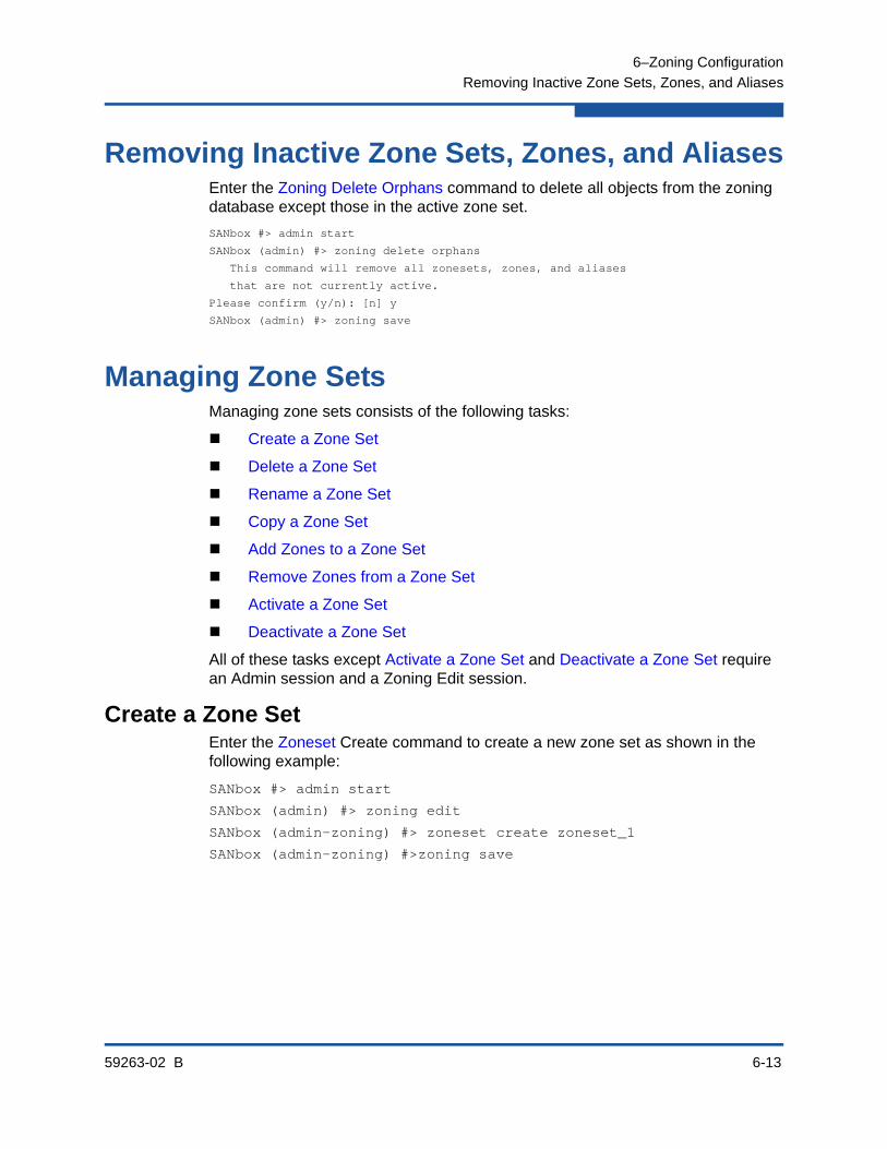
6–Zoning Configuration
Removing Inactive Zone Sets, Zones, and Aliases
59263-02 B 6-13
Removing Inactive Zone Sets, Zones, and AliasesEnter the Zoning Delete Orphans command to delete all objects from the zoning database except those in the active zone set.
SANbox #> admin start
SANbox (admin) #> zoning delete orphans
This command will remove all zonesets, zones, and aliases
that are not currently active.
Please confirm (y/n): [n] y
SANbox (admin) #> zoning save
Managing Zone SetsManaging zone sets consists of the following tasks:
Create a Zone Set
Delete a Zone Set
Rename a Zone Set
Copy a Zone Set
Add Zones to a Zone Set
Remove Zones from a Zone Set
Activate a Zone Set
Deactivate a Zone Set
All of these tasks except Activate a Zone Set and Deactivate a Zone Set require an Admin session and a Zoning Edit session.
Create a Zone SetEnter the Zoneset Create command to create a new zone set as shown in the following example:
SANbox #> admin start
SANbox (admin) #> zoning edit
SANbox (admin-zoning) #> zoneset create zoneset_1
SANbox (admin-zoning) #>zoning save
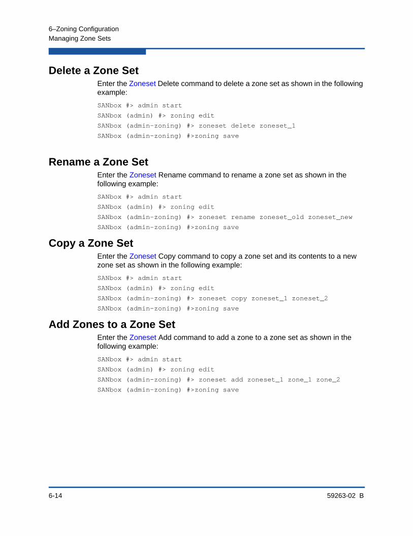
6–Zoning Configuration
Managing Zone Sets
6-14 59263-02 B
Delete a Zone SetEnter the Zoneset Delete command to delete a zone set as shown in the following example:
SANbox #> admin start
SANbox (admin) #> zoning edit
SANbox (admin-zoning) #> zoneset delete zoneset_1
SANbox (admin-zoning) #>zoning save
Rename a Zone SetEnter the Zoneset Rename command to rename a zone set as shown in the following example:
SANbox #> admin start
SANbox (admin) #> zoning edit
SANbox (admin-zoning) #> zoneset rename zoneset_old zoneset_new
SANbox (admin-zoning) #>zoning save
Copy a Zone SetEnter the Zoneset Copy command to copy a zone set and its contents to a new zone set as shown in the following example:
SANbox #> admin start
SANbox (admin) #> zoning edit
SANbox (admin-zoning) #> zoneset copy zoneset_1 zoneset_2
SANbox (admin-zoning) #>zoning save
Add Zones to a Zone SetEnter the Zoneset Add command to add a zone to a zone set as shown in the following example:
SANbox #> admin start
SANbox (admin) #> zoning edit
SANbox (admin-zoning) #> zoneset add zoneset_1 zone_1 zone_2
SANbox (admin-zoning) #>zoning save
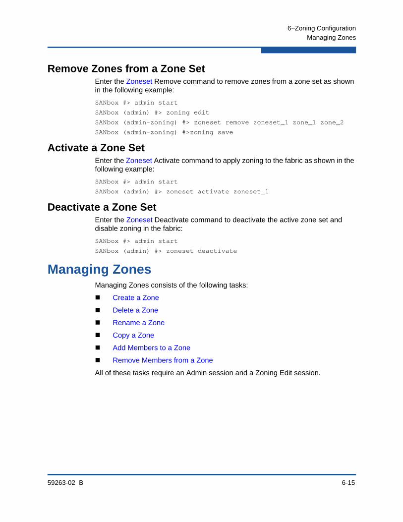
6–Zoning Configuration
Managing Zones
59263-02 B 6-15
Remove Zones from a Zone SetEnter the Zoneset Remove command to remove zones from a zone set as shown in the following example:
SANbox #> admin start
SANbox (admin) #> zoning edit
SANbox (admin-zoning) #> zoneset remove zoneset_1 zone_1 zone_2
SANbox (admin-zoning) #>zoning save
Activate a Zone SetEnter the Zoneset Activate command to apply zoning to the fabric as shown in the following example:
SANbox #> admin start
SANbox (admin) #> zoneset activate zoneset_1
Deactivate a Zone SetEnter the Zoneset Deactivate command to deactivate the active zone set and disable zoning in the fabric:
SANbox #> admin start
SANbox (admin) #> zoneset deactivate
Managing ZonesManaging Zones consists of the following tasks:
Create a Zone
Delete a Zone
Rename a Zone
Copy a Zone
Add Members to a Zone
Remove Members from a Zone
All of these tasks require an Admin session and a Zoning Edit session.

6–Zoning Configuration
Managing Zones
6-16 59263-02 B
Create a ZoneEnter the Zone Create command to create a new zone as shown in the following example:
SANbox #> admin start
SANbox (admin) #> zoning edit
SANbox (admin-zoning) #> zone create zone_1
SANbox (admin-zoning) #> zoning save
Delete a ZoneEnter the Zone Delete command to delete zone_1 from the zoning database as shown in the following example:
SANbox #> admin start
SANbox (admin) #> zoning edit
SANbox (admin-zoning) #> zone delete zone_1
SANbox (admin-zoning) #> zoning save
Rename a ZoneEnter the Zone Rename command to rename zone_1 to zone_a as shown in the following example:
SANbox #> admin start
SANbox (admin) #> zoning edit
SANbox (admin-zoning) #> zone rename zone_1 zone_a
SANbox (admin-zoning) #> zoning save
Copy a ZoneEnter the Zone Copy command to copy the contents of an existing zone (zone_1) to a new zone (zone_2) as shown in the following example:
SANbox #> admin start
SANbox (admin) #> zoning edit
SANbox (admin-zoning) #> zone copy zone_1 zone_2
SANbox (admin-zoning) #> zoning save

6–Zoning Configuration
Managing Aliases
59263-02 B 6-17
Add Members to a ZoneEnter the Zone Add command to add ports/devices to zone_1 as shown in the following example:
SANbox #> admin start
SANbox (admin) #> zoning edit
SANbox (admin-zoning) #> zone add zone_1 alias_1 1,4 1,5
SANbox (admin-zoning) #> zoning save
Remove Members from a ZoneEnter the Zone Remove command to remove ports/devices from zone_1 as shown in the following example:
SANbox #> admin start
SANbox (admin) #> zoning edit
SANbox (admin-zoning) #> zone remove zone_1 alias_1 1,4 1,5
SANbox (admin-zoning) #> zoning save
Managing AliasesManaging aliases consists of the following tasks:
Create an Alias
Delete an Alias
Rename an Alias
Copy an Alias
Add Members to an Alias
Remove Members from an Alias
All of these tasks require an Admin session and a Zoning Edit session.
Create an AliasEnter the Alias Create command to create a new alias as shown in the following example:
SANbox #> admin start
SANbox (admin) #> zoning edit
SANbox (admin-zoning) #> alias create alias_1
SANbox (admin-zoning) #> zoning save

6–Zoning Configuration
Managing Aliases
6-18 59263-02 B
Delete an AliasEnter the Alias Delete command to delete alias_1 from the zoning database as shown in the following example:
SANbox #> admin start
SANbox (admin) #> zoning edit
SANbox (admin-zoning) #> alias delete alias_1
SANbox (admin-zoning) #> zoning save
Rename an AliasEnter the Alias Rename command to rename alias_1 to alias_a as shown in the following example:
SANbox #> admin start
SANbox (admin) #> zoning edit
SANbox (admin-zoning) #> alias rename alias_1 alias_a
SANbox (admin-zoning) #> zoning save
Copy an AliasEnter the Alias Copy command to copy alias_1 and its contents to alias_2 as shown in the following example:
SANbox #> admin start
SANbox (admin) #> zoning edit
SANbox (admin-zoning) #> alias copy alias_1 alias_2
SANbox (admin-zoning) #> zoning save
Add Members to an AliasEnter the Alias Add command to add ports/devices to alias_1 as shown in the following example:
SANbox #> admin start
SANbox (admin) #> zoning edit
SANbox (admin-zoning) #> alias add alias_1 1,4 1,5
SANbox (admin-zoning) #> zoning save
Remove Members from an AliasEnter the Alias Remove command to remove ports/devices from alias_1 as shown in the following example:
SANbox #> admin start
SANbox (admin) #> zoning edit
SANbox (admin-zoning) #> alias remove alias_1 1,4 1,5
SANbox (admin-zoning) #> zoning save

59263-02 B 7-1
7 Connection Security Configuration
This section describes the following tasks:
Managing SSL and SSH Services
Displaying SSL and SSH Services
Creating an SSL Security Certificate
The switch supports secure connections with Telnet and switch management applications. The Secure SHell protocol (SSH) secures Telnet connections to the switch. The Secure Sockets Layer (SSL) protocol secures switch connections to the following management applications:
Enterprise Fabric Suite
QuickTools
Application Programming Interface
Storage Management Initiative-Specification (SMI-S)

7–Connection Security Configuration
Managing SSL and SSH Services
7-2 59263-02 B
Managing SSL and SSH ServicesConsider the following when enabling SSH and SSL services:
To establish a secure Telnet connection, your workstation must use an SSH client.
To enable secure SSL connections, you must first synchronize the date and time on the switch and workstation. Refer to “Setting the Date and Time” on page 4-16.
The SSL service must be enabled to authenticate users through a RADIUS server. Refer to “Configuring a RADIUS Server on the Switch” on page 9-3.
To disable SSL when using a user authentication RADIUS server, the RADIUS server authentication order must be local.
Enabling SSL automatically creates a security certificate on the switch.
Enter the Set Setup Services command to manage both SSH and SSL services as shown in the following example:
SANbox #> admin start
SANbox (admin) #> set setup services
A list of attributes with formatting and current values will follow. Enter a new value or simply press the ENTER key to accept the current value. If you wish to terminate this process before reaching the end of the list press 'q' or 'Q' and the ENTER key to do so.
PLEASE NOTE: ----------- * Further configuration may be required after enabling a service.
* If services are disabled, the connection to the switch may be lost.
* When enabling SSL, please verify that the date/time settings on this switch and the workstation from where the SSL connection will be started match, and then a new certificate may need to be created to ensure a secure connection to this switch.
TelnetEnabled (True / False) [True ]
SSHEnabled (True / False) [False] True
GUIMgmtEnabled (True / False) [True ]
SSLEnabled (True / False) [False] True
EmbeddedGUIEnabled (True / False) [True ]
SNMPEnabled (True / False) [True ]
NTPEnabled (True / False) [False]
CIMEnabled (True / False) [False]
FTPEnabled (True / False) [True ]
MgmtServerEnabled (True / False) [True ]
Do you want to save and activate this services setup? (y/n): [n] y
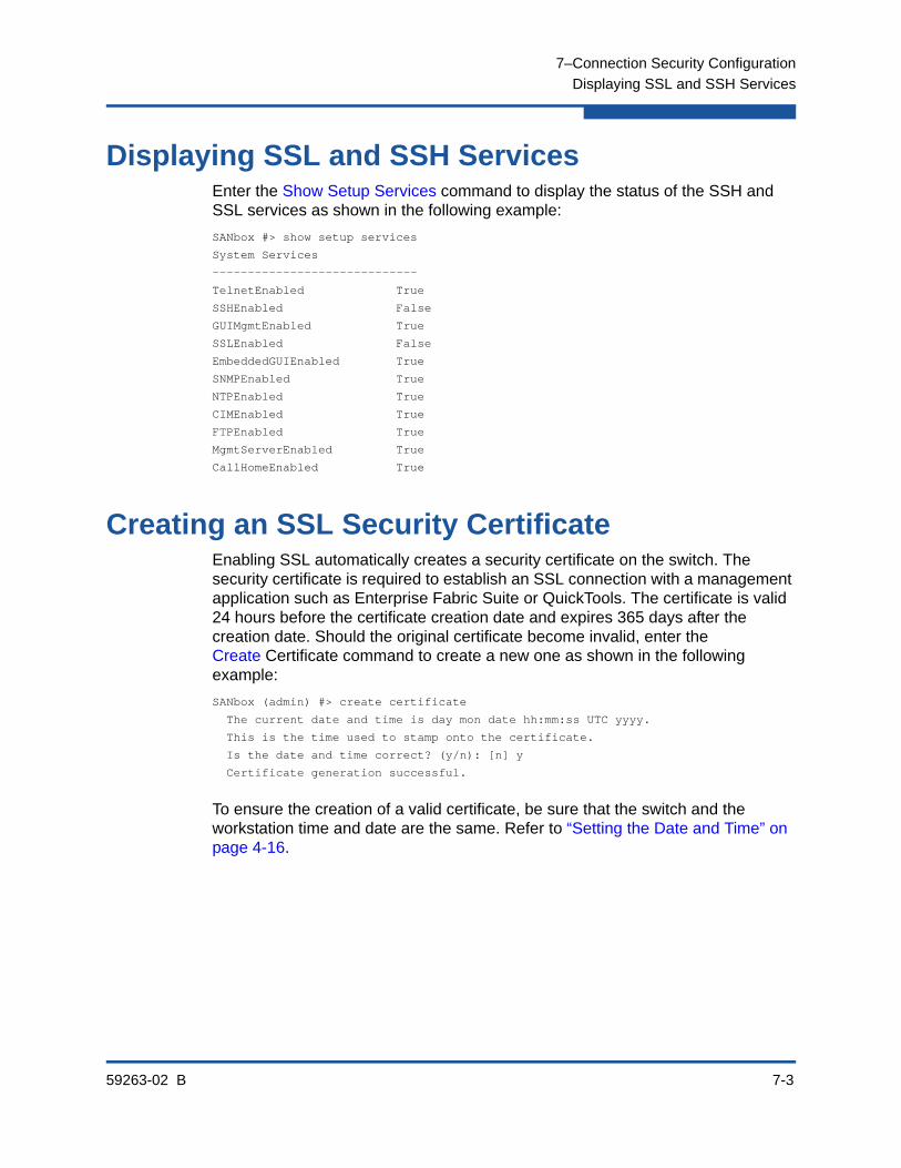
7–Connection Security Configuration
Displaying SSL and SSH Services
59263-02 B 7-3
Displaying SSL and SSH ServicesEnter the Show Setup Services command to display the status of the SSH and SSL services as shown in the following example:
SANbox #> show setup services
System Services
-----------------------------
TelnetEnabled True
SSHEnabled False
GUIMgmtEnabled True
SSLEnabled False
EmbeddedGUIEnabled True
SNMPEnabled True
NTPEnabled True
CIMEnabled True
FTPEnabled True
MgmtServerEnabled True
CallHomeEnabled True
Creating an SSL Security CertificateEnabling SSL automatically creates a security certificate on the switch. The security certificate is required to establish an SSL connection with a management application such as Enterprise Fabric Suite or QuickTools. The certificate is valid 24 hours before the certificate creation date and expires 365 days after the creation date. Should the original certificate become invalid, enter the Create Certificate command to create a new one as shown in the following example:
SANbox (admin) #> create certificate
The current date and time is day mon date hh:mm:ss UTC yyyy.
This is the time used to stamp onto the certificate.
Is the date and time correct? (y/n): [n] y
Certificate generation successful.
To ensure the creation of a valid certificate, be sure that the switch and the workstation time and date are the same. Refer to “Setting the Date and Time” on page 4-16.

7–Connection Security Configuration
Creating an SSL Security Certificate
7-4 59263-02 B
59263-02 B 8-1
8 Device Security Configuration
This section describes the following tasks:
Displaying Security Database Information
Configuring the Security Database
Modifying the Security Database
Resetting the Security Database
Managing Security Sets
Managing Groups
Device security provides for the authorization and authentication of devices that you attach to a switch. You can configure a switch with a group of devices against which the switch authorizes new attachments by devices, other switches, or devices issuing management server commands.
Device security is defined through the use of security sets and groups. A group is a list of device worldwide names that are authorized to attach to a switch. There are three types of groups: one for other switches (ISL), another for devices (port), and a third for devices issuing management server commands (MS). A security set is a set of up to three groups with no more than one of each group type. The security database is made up of all security sets on the switch.
In addition to authorization, the switch can be configured to require authentication to validate the identity of the connecting switch, device, or host. Authentication can be performed locally using the switch’s security database, or remotely using a Remote Dial-In User Service (RADIUS) server such as Microsoft® RADIUS.
Displaying Security Database InformationYou can display the following information about the security database:
Configured Security Set Information
Active Security Set Information
Security Set Membership Information
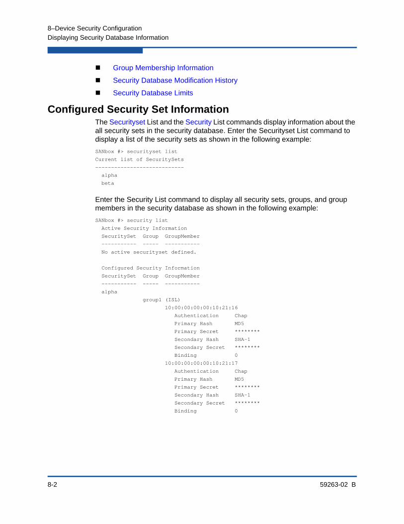
8–Device Security Configuration
Displaying Security Database Information
8-2 59263-02 B
Group Membership Information
Security Database Modification History
Security Database Limits
Configured Security Set InformationThe Securityset List and the Security List commands display information about the all security sets in the security database. Enter the Securityset List command to display a list of the security sets as shown in the following example:
SANbox #> securityset list
Current list of SecuritySets
----------------------------
alpha
beta
Enter the Security List command to display all security sets, groups, and group members in the security database as shown in the following example:
SANbox #> security list
Active Security Information
SecuritySet Group GroupMember
----------- ----- -----------
No active securityset defined.
Configured Security Information
SecuritySet Group GroupMember
----------- ----- -----------
alpha
group1 (ISL)
10:00:00:00:00:10:21:16
Authentication Chap
Primary Hash MD5
Primary Secret ********
Secondary Hash SHA-1
Secondary Secret ********
Binding 0
10:00:00:00:00:10:21:17
Authentication Chap
Primary Hash MD5
Primary Secret ********
Secondary Hash SHA-1
Secondary Secret ********
Binding 0

8–Device Security Configuration
Displaying Security Database Information
59263-02 B 8-3
Active Security Set InformationThe Security Active and Securityset Active commands display information about the active security set. Enter the Security Active command to display component groups and group members as shown in the following example:
SANbox #> security active
Active Security Information
SecuritySet Group GroupMember
----------- ----- -----------
alpha
group1 (ISL)
10:00:00:00:00:10:21:16
Authentication Chap
Primary Hash MD5
Primary Secret ********
Secondary Hash SHA-1
Secondary Secret ********
Binding 0
10:00:00:00:00:10:21:17
Authentication Chap
Primary Hash MD5
Primary Secret ********
Secondary Hash SHA-1
Secondary Secret ********
Binding 0
Enter the Securityset Active command to display the name of the active security set and its activation history as shown in the following example:
SANbox #> securityset active
Active SecuritySet Information
------------------------------
ActiveSecuritySet alpha
LastActivatedBy Remote
LastActivatedOn day month date time year

8–Device Security Configuration
Displaying Security Database Information
8-4 59263-02 B
Security Set Membership InformationThe Securityset Groups and Group Securitysets commands display security set membership information. Enter the Securityset Groups command to display the member groups for a specified security set as shown in the following example:
SANbox #> securityset groups alpha
Current list of Groups for SecuritySet: alpha
---------------------------------------
group1 (ISL)
group2 (Port)
Enter the Group Securitysets command to display the security sets for which a specified group is a member as shown in the following example:
SANbox #> group securitysets group_1
Current list of SecuritySets for Group: group_1
---------------------------------------
SecuritySet_1
SecuritySet_2
SecuritySet_A
SecuritySet_B
Group Membership InformationEnter the Group Members command to display the members for a specified group as shown in the following example:
SANbox #> group members group_1
Current list of members for Group: group_1
----------------------------------
10:00:00:c0:dd:00:71:ed
10:00:00:c0:dd:00:72:45
10:00:00:c0:dd:00:90:ef
10:00:00:c0:dd:00:b8:b7
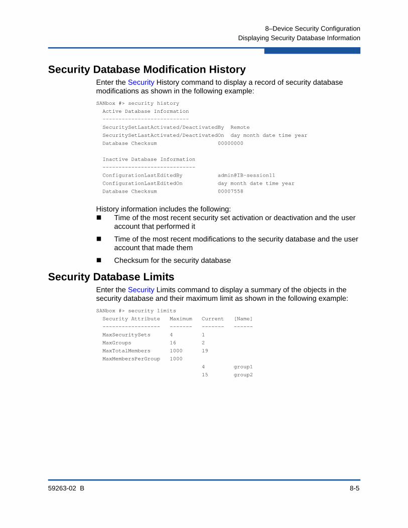
8–Device Security Configuration
Displaying Security Database Information
59263-02 B 8-5
Security Database Modification HistoryEnter the Security History command to display a record of security database modifications as shown in the following example:
SANbox #> security history
Active Database Information
---------------------------
SecuritySetLastActivated/DeactivatedBy Remote
SecuritySetLastActivated/DeactivatedOn day month date time year
Database Checksum 00000000
Inactive Database Information
-----------------------------
ConfigurationLastEditedBy admin@IB-session11
ConfigurationLastEditedOn day month date time year
Database Checksum 00007558
History information includes the following: Time of the most recent security set activation or deactivation and the user
account that performed it
Time of the most recent modifications to the security database and the user account that made them
Checksum for the security database
Security Database LimitsEnter the Security Limits command to display a summary of the objects in the security database and their maximum limit as shown in the following example:
SANbox #> security limits
Security Attribute Maximum Current [Name]
------------------ ------- ------- ------
MaxSecuritySets 4 1
MaxGroups 16 2
MaxTotalMembers 1000 19
MaxMembersPerGroup 1000
4 group1
15 group2

8–Device Security Configuration
Configuring the Security Database
8-6 59263-02 B
Configuring the Security DatabaseYou can configure how the security database is applied to the switch and exchanged with the fabric through the security configuration parameters. The following security configuration parameters are available through the Set Config Security command:
AutoSave–This parameter enables or disables the saving of changes to active security set in the switch’s non-volatile security database.
FabricBindingEnabled–This parameter enables or disables the configuration and enforcement of fabric binding on all switches in the fabric. Fabric binding associates switch worldwide names with a domain ID in the creation of ISL groups.
If AutoSave is False, you can revert device security changes that have been received from another switch through the activation of a security set, or merging of fabrics. Enter the Security Restore command to replace the volatile security database with the contents of the non-volatile security database.
To restore the security configuration to its factory values, you can enter the Reset Config or Reset Factory command. Notice however, that these commands restore other aspects of the switch configuration also.

8–Device Security Configuration
Configuring the Security Database
59263-02 B 8-7
To modify the security configuration, you must open an Admin session with the Admin Start command. An Admin session prevents other accounts from making changes at the same time either through the CLI, QuickTools, or Enterprise Fabric Suite. You must also open a Config Edit session with the Config Edit command and indicate which configuration you want to modify. If you do not specify a configuration name, the active configuration is assumed. The Config Edit session provides access to the Set Config Security command as shown in the following example:
SANbox #> admin start
SANbox (admin) #> config edit
SANbox (admin-config) #> set config security
A list of attributes with formatting and current values will follow. Enter a new value or simply press the ENTER key to accept the current value. If you wish to terminate this process before reaching the end of the list press 'q' or 'Q' and the ENTER key to do so.
FabricBindingEnabled (True / False) [False]
AutoSave (True / False) [True ]
Finished configuring attributes. This configuration must be saved (see config save command) and activated (see config activate command) before it can take effect. To discard this configuration use the config cancel command.
SANbox (admin-config)#> config save
SANbox (admin)#> config activate
SANbox (admin)#> admin end

8–Device Security Configuration
Modifying the Security Database
8-8 59263-02 B
Modifying the Security DatabaseTo modify the security database, you must open an Admin session with the Admin Start command. An Admin session prevents other accounts from making changes at the same time either through the CLI, QuickTools, or Enterprise Fabric Suite. You must also open a Security Edit session with the Security Edit command. The Security Edit session provides access to the Securityset, Group, and Security commands with which you make modifications to the security database.
SANbox #> admin start
SANbox (admin) #> security edit
SANbox (admin-security)#> securityset . . .
SANbox (admin-security)#> group . . .
SANbox (admin-security)#> security . . .
When you are finished making changes, enter the Security Save command to save the changes and close the Security Edit session.
SANbox (admin-security)#> security save
To close the session without saving changes, enter the Security Cancel command.
SANbox (admin-security)#> security cancel
Changes to the active security set do not take effect until you activate it with the Security Activate command. The Admin End command releases the Admin session for other administrators when you are done making changes to the switch.
SANbox (admin)#> security activate
SANbox (admin)#> admin end
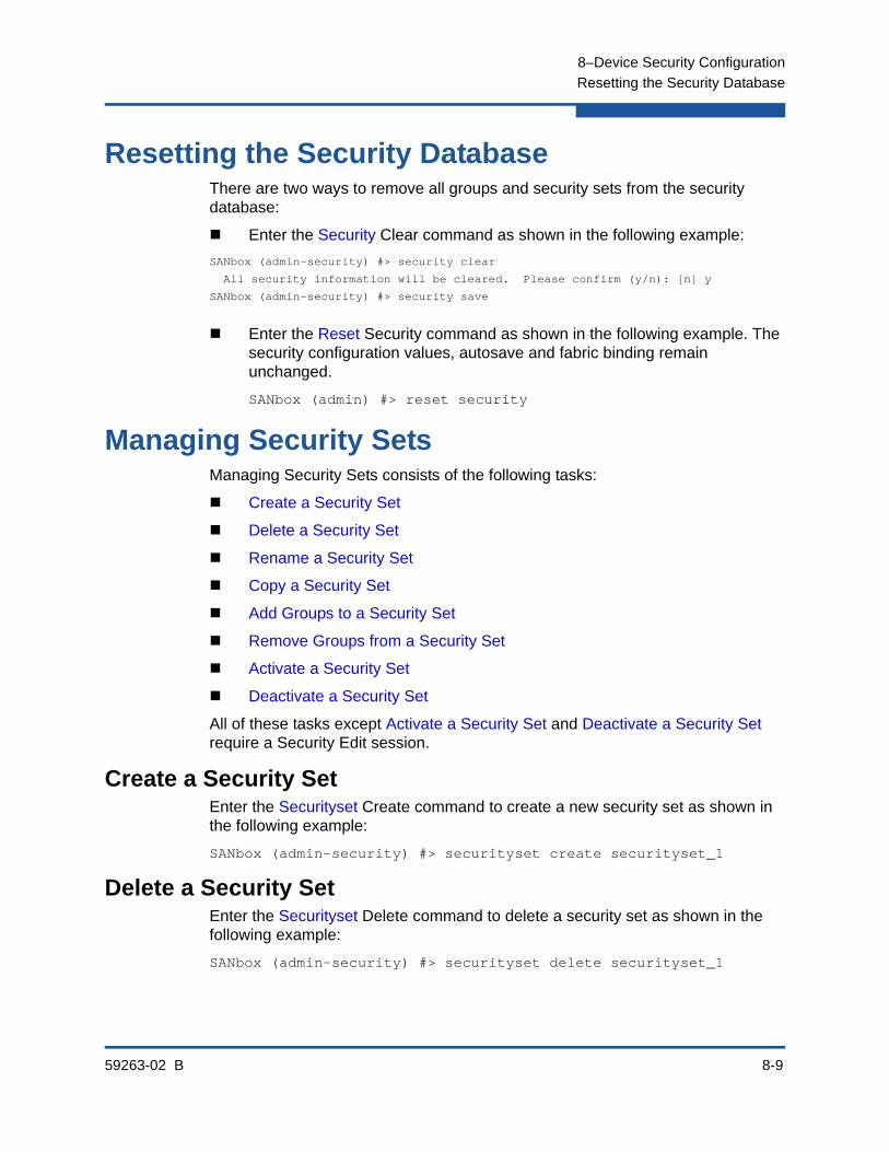
8–Device Security Configuration
Resetting the Security Database
59263-02 B 8-9
Resetting the Security DatabaseThere are two ways to remove all groups and security sets from the security database:
Enter the Security Clear command as shown in the following example:
SANbox (admin-security) #> security clear
All security information will be cleared. Please confirm (y/n): [n] y
SANbox (admin-security) #> security save
Enter the Reset Security command as shown in the following example. The security configuration values, autosave and fabric binding remain unchanged.
SANbox (admin) #> reset security
Managing Security SetsManaging Security Sets consists of the following tasks:
Create a Security Set
Delete a Security Set
Rename a Security Set
Copy a Security Set
Add Groups to a Security Set
Remove Groups from a Security Set
Activate a Security Set
Deactivate a Security Set
All of these tasks except Activate a Security Set and Deactivate a Security Set require a Security Edit session.
Create a Security SetEnter the Securityset Create command to create a new security set as shown in the following example:
SANbox (admin-security) #> securityset create securityset_1
Delete a Security SetEnter the Securityset Delete command to delete a security set as shown in the following example:
SANbox (admin-security) #> securityset delete securityset_1
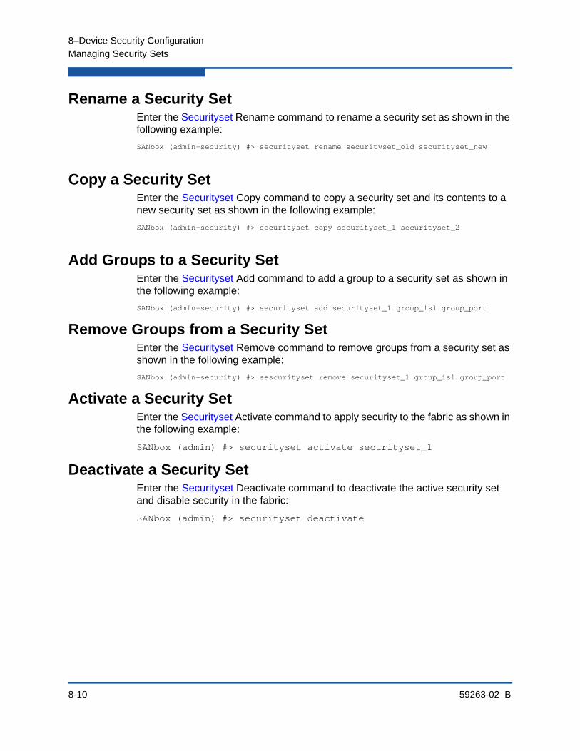
8–Device Security Configuration
Managing Security Sets
8-10 59263-02 B
Rename a Security SetEnter the Securityset Rename command to rename a security set as shown in the following example:
SANbox (admin-security) #> securityset rename securityset_old securityset_new
Copy a Security SetEnter the Securityset Copy command to copy a security set and its contents to a new security set as shown in the following example:
SANbox (admin-security) #> securityset copy securityset_1 securityset_2
Add Groups to a Security SetEnter the Securityset Add command to add a group to a security set as shown in the following example:
SANbox (admin-security) #> securityset add securityset_1 group_isl group_port
Remove Groups from a Security SetEnter the Securityset Remove command to remove groups from a security set as shown in the following example:
SANbox (admin-security) #> sescurityset remove securityset_1 group_isl group_port
Activate a Security SetEnter the Securityset Activate command to apply security to the fabric as shown in the following example:
SANbox (admin) #> securityset activate securityset_1
Deactivate a Security SetEnter the Securityset Deactivate command to deactivate the active security set and disable security in the fabric:
SANbox (admin) #> securityset deactivate
8–Device Security Configuration
Managing Groups
59263-02 B 8-11
Managing GroupsManaging Groups consists of the following tasks:
Create a Group
Delete a Group
Rename a Group
Copy a Group
Add Members to a Group
Modify a Group Member
Remove Members from a Group
All of these tasks require an Admin session and a Security Edit session.
Create a GroupCreating a group involves specifying a group name and a group type. There are three types of groups:
ISL group–secures connected switches
Port group–secures connected devices
MS group–secures management server commands
Enter the Group Create command to create a new port group as shown in the following example:
SANbox (admin-security) #> group create group_port port
Delete a GroupEnter the Group Delete command to delete group_port from the security database as shown in the following example:
SANbox (admin-security) #> group delete group_port
Rename a GroupEnter the Group Rename command to rename group_port to port_1 as shown in the following example:
SANbox (admin-security) #> group rename group_port port_1
Copy a GroupEnter the Group Copy command to copy the contents of an existing group (group_port) to a new group (port_1) as shown in the following example:
SANbox (admin-security) #> group copy group_port port_1

8–Device Security Configuration
Managing Groups
8-12 59263-02 B
Add Members to a GroupAdding a member to a group involves specifying a group, the member worldwide name, and the member attributes. The member attributes define the authentication method, encryption method, secrets, and fabric binding, depending on the group type.
For ISL member attributes, refer to Table 13-2.
For Port member attributes, refer to Table 13-3.
For MS member attributes, refer to Table 13-4.
Enter the Group Add command to add a member to a group:
SANbox #> admin start
SANbox (admin) #> security edit
SANbox (admin-security) #> group add Group_1
A list of attributes with formatting and default values will follow Enter a new value or simply press the ENTER key to accept the current value with exception of the Group Member WWN field which is mandatory. If you wish to terminate this process before reaching the end of the list press 'q' or 'Q' and the ENTER key to do so.
Group Name Group_1
Group Type ISL
Member (WWN) [00:00:00:00:00:00:00:00] 10:00:00:c0:dd:00:90:a3
Authentication (None / Chap) [None ] chap
PrimaryHash (MD5 / SHA-1) [MD5 ]
PrimarySecret (32 hex or 16 ASCII char value) [ ] 0123456789abcdef
SecondaryHash (MD5 / SHA-1 / None) [None ]
SecondarySecret (40 hex or 20 ASCII char value) [ ]
Binding (domain ID 1-239, 0=None) [0 ]
Finished configuring attributes. To discard this configuration use the security cancel command.

8–Device Security Configuration
Managing Groups
59263-02 B 8-13
Modify a Group MemberModifying a group member involves changing the member attributes. The member attributes define the authentication method, encryption methods, secrets, and fabric binding, depending on the group type.
For ISL member attributes, refer to Table 13-2.
For Port member attributes, refer to Table 13-3.
For MS member attributes, refer to Table 13-4.
Enter the Group Edit command to change the attributes of a group member:
SANbox #> admin start
SANbox (admin) #> security edit
SANbox (admin-security) #> group edit G1 10:00:00:c0:dd:00:90:a3 A list of attributes with formatting and current values will follow. Enter a new value or simply press the ENTER key to accept the current value. If you wish to terminate this process before reaching the end of the list press 'q' or 'Q' and the ENTER key to do so.
Group Name g1
Group Type ISL
Group Member 10:00:00:c0:dd:00:90:a3
Authentication (None / Chap) [None] chap
PrimaryHash (MD5 / SHA-1) [MD5 ] sha-1
PrimarySecret (40 hex or 20 ASCII char value) [ ] 12345678901234567890
SecondaryHash (MD5 / SHA-1 / None) [None] md5
SecondarySecret (32 hex or 16 ASCII char value) [ ] 1234567890123456
Binding (domain ID 1-239, 0=None) [3 ]
Finished configuring attributes. To discard this configuration use the security cancel command.
Remove Members from a GroupEnter the Group Remove command to remove a member from a group as shown in the following example:
SANbox (admin-security) #> group remove group_1 10:00:00:c0:dd:00:90:a3

8–Device Security Configuration
Managing Groups
8-14 59263-02 B
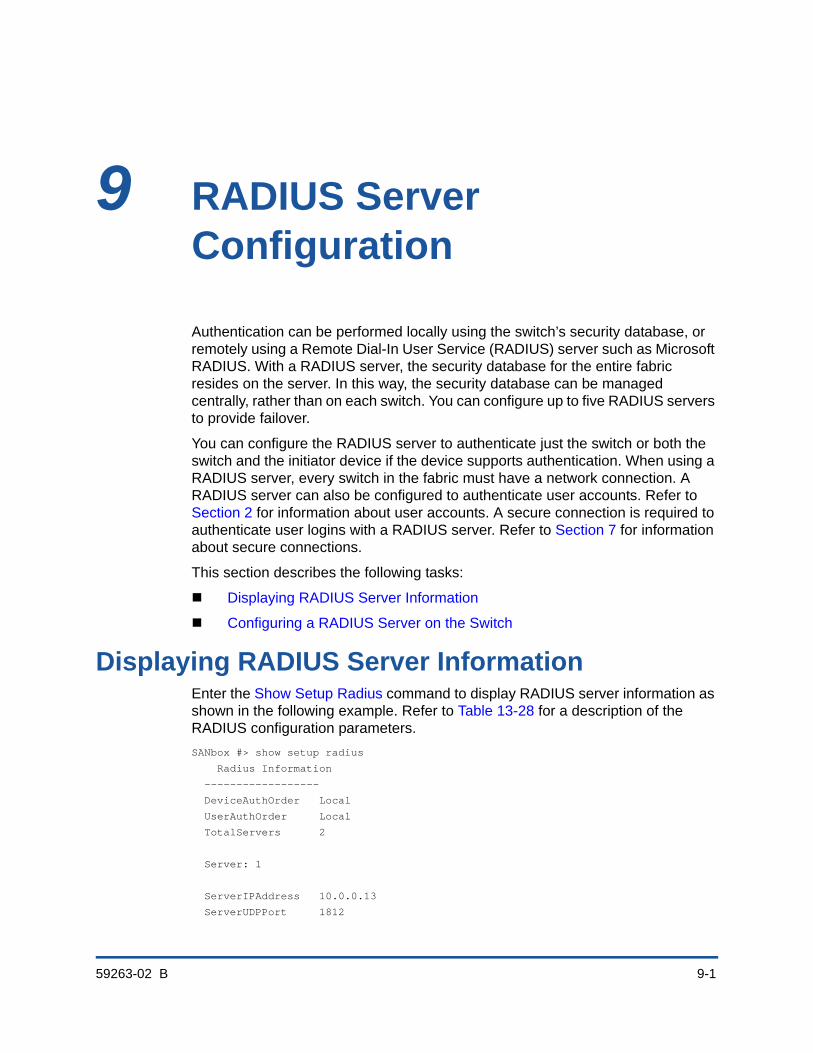
59263-02 B 9-1
9 RADIUS Server Configuration
Authentication can be performed locally using the switch’s security database, or remotely using a Remote Dial-In User Service (RADIUS) server such as Microsoft RADIUS. With a RADIUS server, the security database for the entire fabric resides on the server. In this way, the security database can be managed centrally, rather than on each switch. You can configure up to five RADIUS servers to provide failover.
You can configure the RADIUS server to authenticate just the switch or both the switch and the initiator device if the device supports authentication. When using a RADIUS server, every switch in the fabric must have a network connection. A RADIUS server can also be configured to authenticate user accounts. Refer to Section 2 for information about user accounts. A secure connection is required to authenticate user logins with a RADIUS server. Refer to Section 7 for information about secure connections.
This section describes the following tasks:
Displaying RADIUS Server Information
Configuring a RADIUS Server on the Switch
Displaying RADIUS Server InformationEnter the Show Setup Radius command to display RADIUS server information as shown in the following example. Refer to Table 13-28 for a description of the RADIUS configuration parameters.
SANbox #> show setup radius
Radius Information
------------------
DeviceAuthOrder Local
UserAuthOrder Local
TotalServers 2
Server: 1
ServerIPAddress 10.0.0.13
ServerUDPPort 1812

9–RADIUS Server Configuration
Displaying RADIUS Server Information
9-2 59263-02 B
DeviceAuthServer False
UserAuthServer False
AccountingServer False
Timeout 2
Retries 0
SignPackets False
Secret ********
Server: 2
ServerIPAddress bacd:1234:bacd:1234:bacd:1234:bacd:1234
ServerUDPPort 1812
DeviceAuthServer True
UserAuthServer True
AccountingServer True
Timeout 2
Retries 0
SignPackets False
Secret ********

9–RADIUS Server Configuration
Configuring a RADIUS Server on the Switch
59263-02 B 9-3
Configuring a RADIUS Server on the SwitchEnter the Set Setup Radius command to configure a RADIUS server on the switch. There are two groups of RADIUS configuration parameters. One group of parameters is common to all RADIUS server configurations. The second group is server specific. You can configure both groups of parameters for all RADIUS servers, or you can configure the common and server-specific parameters separately. Refer to Table 13-28 for a description of the common and server-specific RADIUS configuration parameters.
The following example configures the common RADIUS server configuration parameters:
SANbox (admin) #> set setup radius common
A list of attributes with formatting and current values will follow. Enter a new value or simply press the ENTER key to accept the current value. If you wish to terminate this process before reaching the end of the attributes for the server being processed, press 'q' or 'Q' and the ENTER key to do so. If you wish to terminate the configuration process completely, press 'qq' or 'QQ' and the ENTER key to so do.
PLEASE NOTE:
-----------
* SSL must be enabled in order to configure RADIUS User Authentication
SSL can be enabled using the 'set setup services' command.
Current Values:
DeviceAuthOrder Local
UserAuthOrder Local
TotalServers 1
New Value (press ENTER to not specify value, 'q' to quit):
DeviceAuthOrder 1=Local, 2=Radius, 3=RadiusLocal :
UserAuthOrder 1=Local, 2=Radius, 3=RadiusLocal :
TotalServers decimal value, 0-5 :
Do you want to save and activate this radius setup? (y/n): [n]
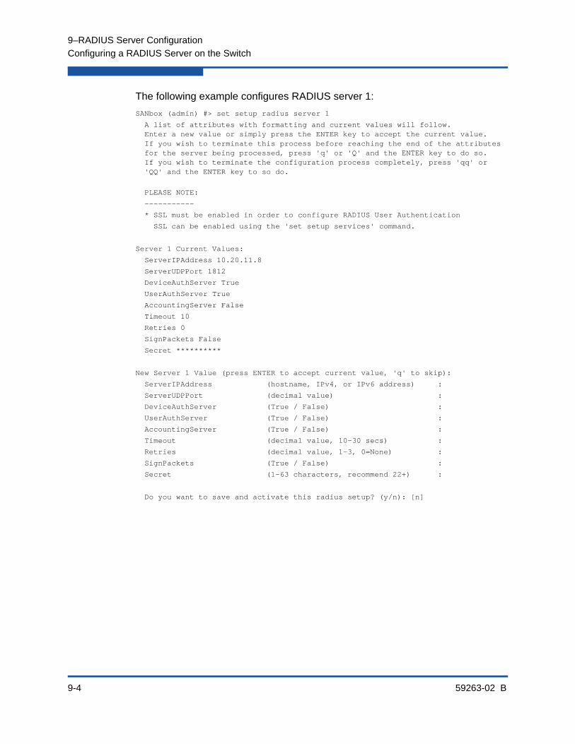
9–RADIUS Server Configuration
Configuring a RADIUS Server on the Switch
9-4 59263-02 B
The following example configures RADIUS server 1:
SANbox (admin) #> set setup radius server 1
A list of attributes with formatting and current values will follow. Enter a new value or simply press the ENTER key to accept the current value. If you wish to terminate this process before reaching the end of the attributes for the server being processed, press 'q' or 'Q' and the ENTER key to do so. If you wish to terminate the configuration process completely, press 'qq' or 'QQ' and the ENTER key to so do.
PLEASE NOTE:
-----------
* SSL must be enabled in order to configure RADIUS User Authentication
SSL can be enabled using the 'set setup services' command.
Server 1 Current Values:
ServerIPAddress 10.20.11.8
ServerUDPPort 1812
DeviceAuthServer True
UserAuthServer True
AccountingServer False
Timeout 10
Retries 0
SignPackets False
Secret **********
New Server 1 Value (press ENTER to accept current value, 'q' to skip):
ServerIPAddress (hostname, IPv4, or IPv6 address) :
ServerUDPPort (decimal value) :
DeviceAuthServer (True / False) :
UserAuthServer (True / False) :
AccountingServer (True / False) :
Timeout (decimal value, 10-30 secs) :
Retries (decimal value, 1-3, 0=None) :
SignPackets (True / False) :
Secret (1-63 characters, recommend 22+) :
Do you want to save and activate this radius setup? (y/n): [n]

59263-02 B 10-1
10 Event Log Configuration
This section describes the following tasks:
Starting and Stopping Event Logging
Displaying the Event Log
Managing the Event Log Configuration
Clearing the Event Log
Logging to a Remote Host
Creating and Downloading a Log File
Event messages originate from the switch or from the management application in response to events that occur in the fabric. Refer to the QLogic Fibre Channel Switch Event Message Reference Guide for a complete listing of switch event messages.
Events are classified by the following severity levels:
Alarm–The alarm level describes events that are disruptive to the administration or operation of a fabric and require administrator intervention. Alarms are always logged and always displayed on the screen. Alarm thresholds can be defined for certain port errors to customize when to generate an alarm.
Critical–The critical level describes events that are generally disruptive to the administration or operation of the fabric, but require no action.
Warning–The warning level describes events that are generally not disruptive to the administration or operation of the fabric, but are more important than the informative level events.
Informative–The informative level describes routine events associated with a normal fabric.

10–Event Log Configuration
Starting and Stopping Event Logging
10-2 59263-02 B
Starting and Stopping Event LoggingEnter the Set Log Stop command in an Admin session to stop recording event messages in the switch Log as shown in the following example:
SANbox (admin) #> set log stop
Enter the Set Log Start command to start recording event message in the switch log as shown in the following example:
SANbox (admin) #> set log start
Displaying the Event LogEnter the Show Log command to display the event log. Each message has the following format:
[ordinal][time_stamp][severity][message_ID][source][message_text]
Table 10-1 describes the message format components.
The following is an example of the Show Log command:
SANbox #> show log
[327][day month date time year][I][Eport Port:0/8][Eport State= E_A0_GET_DOMAIN_ID]
[328][day month date time year][I][Eport Port: 0/8][FSPF PortUp state=0]
[329][day month date time year][I][Eport Port: 0/8][Sending init hello]
Table 10-1. Event Log Message Format
Component Description
[ordinal] A number assigned to each message in sequence since the last time the alarm history was cleared.
[time_stamp] The time the alarm was issued in the format day month hh:mm:ss.ms UTC yyyy. This time stamp comes from the switch for events that originate with the switch, and from the workstation for events that originate with QuickTools or Enterprise Fabric Suite.
[severity] The event severity: A–Alarm, C–Critical, W–Warning, I–Informative
[message_ID] A number that identifies the message using the following format: cat-egory.message_number
[source] The program module or application that generated the event. Sources include Zoning, Switch, PortApp, EPort, Management Server. Alarms do not include the source.
[message_text] The message text
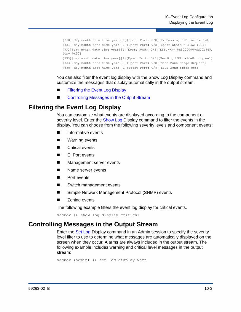
10–Event Log Configuration
Displaying the Event Log
59263-02 B 10-3
[330][day month date time year][I][Eport Port: 0/8][Processing EFP, oxid= 0x8]
[331][day month date time year][I][Eport Port: 0/8][Eport State = E_A2_IDLE]
[332][day month date time year][I][Eport Port: 0/8][EFP,WWN= 0x100000c0dd00b845, len= 0x30]
[333][day month date time year][I][Eport Port: 0/8][Sending LSU oxid=0xc:type=1]
[334][day month date time year][I][Eport Port: 0/8][Send Zone Merge Request]
[335][day month date time year][I][Eport Port: 0/8][LSDB Xchg timer set]
You can also filter the event log display with the Show Log Display command and customize the messages that display automatically in the output stream.
Filtering the Event Log Display
Controlling Messages in the Output Stream
Filtering the Event Log DisplayYou can customize what events are displayed according to the component or severity level. Enter the Show Log Display command to filter the events in the display. You can choose from the following severity levels and component events:
Informative events
Warning events
Critical events
E_Port events
Management server events
Name server events
Port events
Switch management events
Simple Network Management Protocol (SNMP) events
Zoning events
The following example filters the event log display for critical events.
SANbox #> show log display critical
Controlling Messages in the Output StreamEnter the Set Log Display command in an Admin session to specify the severity level filter to use to determine what messages are automatically displayed on the screen when they occur. Alarms are always included in the output stream. The following example includes warning and critical level messages in the output stream:
SANbox (admin) #> set log display warn
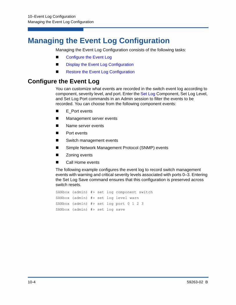
10–Event Log Configuration
Managing the Event Log Configuration
10-4 59263-02 B
Managing the Event Log ConfigurationManaging the Event Log Configuration consists of the following tasks:
Configure the Event Log
Display the Event Log Configuration
Restore the Event Log Configuration
Configure the Event LogYou can customize what events are recorded in the switch event log according to component, severity level, and port. Enter the Set Log Component, Set Log Level, and Set Log Port commands in an Admin session to filter the events to be recorded. You can choose from the following component events:
E_Port events
Management server events
Name server events
Port events
Switch management events
Simple Network Management Protocol (SNMP) events
Zoning events
Call Home events
The following example configures the event log to record switch management events with warning and critical severity levels associated with ports 0–3. Entering the Set Log Save command ensures that this configuration is preserved across switch resets.
SANbox (admin) #> set log component switch
SANbox (admin) #> set log level warn
SANbox (admin) #> set log port 0 1 2 3
SANbox (admin) #> set log save

10–Event Log Configuration
Clearing the Event Log
59263-02 B 10-5
Display the Event Log ConfigurationEnter the Show Log Settings command to display all event log configuration settings as shown in the following example:
SANbox #> show log settings
Current settings for log
------------------------
Started True
FilterComponent NameServer MgmtServer Zoning Switch Port Eport Snmp CLI QFS
FilterLevel Info
DisplayLevel Critical
FilterPort 0 1 2 3 4 5 6 7 8 9 10 11 12 13 14 15 16 17 18 19 20 21 22 23
Restore the Event Log ConfigurationEnter the Set Log Restore command in an Admin session to return the event log configuration to the factory default as shown in the following example:
SANbox (admin) #> set log restore
Clearing the Event LogEnter the Set Log Clear command in an Admin session to delete all entries in the event log as shown in the following example:
SANbox (admin) #> set log clear
Logging to a Remote HostThe switch comes from the factory with local logging enabled, which instructs the switch firmware to maintain an event log in switch memory. The switch can also be configured to log events to a remote host that supports the syslog protocol. This requires that you enable remote logging on the switch and specify an IP address for the remote host.
NOTE:
To log event messages on a remote host, you must edit the syslog.conf file on the remote host and then restart the syslog daemon. The syslog.conf file must contain an entry that specifies the name of the log file. Add the following line to the syslog.conf file. A <tab> separates the selector field (local0.info) and action field which contains the log file path name (/var/adm/messages/messages.name).
local0.info <tab> /var/adm/messages/messages.name
Consult your host operating system documentation for information on how to configure remote logging.

10–Event Log Configuration
Creating and Downloading a Log File
10-6 59263-02 B
Enter the Set Setup System Logging command to control local logging through the LocalLogEnabled parameter, and remote logging through the RemoteLogEnabled and RemoteLogHostAddress parameters as shown in the following example:
SANbox (admin) #> set setup system logging
A list of attributes with formatting and current values will follow.
Enter a new value or simply press the ENTER key to accept the current value.
If you wish to terminate this process before reaching the end of the list
press 'q' or 'Q' and the ENTER key to do so.
Current Values:
LocalLogEnabled True
RemoteLogEnabled False
RemoteLogHostAddress 10.0.0.254
New Value (press ENTER to accept current value, 'q' to quit, 'n' for none):
LocalLogEnabled (True / False) :
RemoteLogEnabled (True / False) :
RemoteLogHostAddress (hostname, IPv4, or IPv6 Address) :
Do you want to save and activate this system setup? (y/n): [n]
Creating and Downloading a Log FileEnter the Set Log Archive command to collect the event log messages in a file on the switch named logfile. This file can have a maximum of 1200 event messages. Use FTP to download the file from the switch to your workstation as follows:
1. Log into the switch through Telnet and create an archive of the event log. Enter the Set Log Archive command in an Admin session to create a file on the switch named logfile.
SANbox #> admin start
SANbox (admin) #> set log archive
2. Open an FTP session on the switch and log in with the account name images and password images. Transfer the file logfile in binary mode with the Get command.
>ftp ip_address
user:images
password: images
ftp>bin
ftp>get logfile
xxxxx bytes sent in xx secs.
ftp>quit

59263-02 B 11-1
11 Call Home Configuration
This section describes the following topics:
Call Home Concepts
Configuring the Call Home Service
Managing the Call Home Database
Testing a Call Home Profile
Changing SMTP Servers
Clearing the Call Home Message Queue
Resetting the Call Home Database
Call Home ConceptsThe Call Home service improves fabric availability by notifying administrators by email of events that affect switch operation. The Call Home service is active by default and is controlled by the Set Setup Services command. To display the Call Home service status, enter the Show Setup Services command. To better understand the Call Home service, consider the following:
Call Home Requirements
Call Home Messages
Technical Support Interface
11–Call Home Configuration
Call Home Concepts
11-2 59263-02 B
Call Home RequirementsIn addition to enabling the Call Home service, you must also do the following to ensure that email messages can be sent:
Configure the Call Home service. The Call Home service configuration consists of primary and secondary SMTP server specifications and contact information. You must enable and specify an address and service port for at least one SMTP server. Refer to “Configuring the Call Home Service” on page 11-5.
Configure the Call Home database The Call Home database consists of up to 25 Call Home profiles. Each profile defines the following:
Event severity levels (Alarm, Critical, Warn) that will initiate an email message
Email message format and subject
Email recipients
Multiple profiles make it possible to notify different audiences based on any combination of event severity, message format (short or full), or message length. You configure profiles using the Profile command within a Callhome Edit session. Refer to “Managing the Call Home Database” on page 11-6.
Ensure that each switch that is to support Call Home email notification has its own Ethernet connection.
Enter the Callhome Test command to test your Call Home service and database configurations. Refer to “Testing a Call Home Profile” on page 11-13.

11–Call Home Configuration
Call Home Concepts
59263-02 B 11-3
Call Home MessagesThe Call Home service generates email messages for the specified event severity level and the following switch actions:
Switch comes online
Switch goes offline
Reboot
Power up
Power down1
SFP failure
When a qualifying switch action or event occurs, an email message is created and placed in the Call Home queue to be sent to the active SMTP server. You can monitor activity in the queue using the Callhome Queue Stats command. You can also clear the queue of email messages using the Callhome Queue Clear command.
There are three email message formats: full text, short text, and Tsc1. The full-text format contains the switch and event information, plus the contact information from the Call Home profile and SNMP configurations. The short-text and Tsc1 formats contains basic switch and event information; Tl is formatted for automated parsing. The following is an example of a short-text email:
From: [email protected] [mailto:[email protected]]
Sent: day, month date, year hh:mm
Subject: [CallHome: Test] Alarm generated on Switch_8
SwitchName: Switch_8_83.215
SwitchIP: 10.20.30.40
SwitchWWN: 10:00:00:c0:dd:0c:66:f2
Level: Alarm
Text: CALLHOME TEST PROFILE MESSAGE
ID: 8B00.0002
Time: day month date hh:mm:ss.343 CDT year
The following is an example of a full-text email including profile and SNMP contact information:
From: [email protected] [mailto:[email protected]]
Sent: day, month date, year hh:mm
Subject: [CallHome: Test] Alarm generated on Switch_8
1 If the switch is forced to power-down before the message is sent to the SMTP server, no messagewill be transmitted.
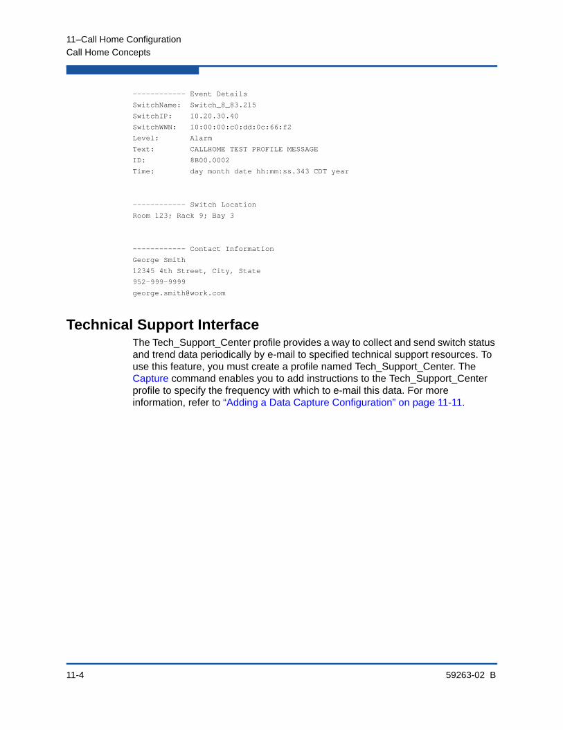
11–Call Home Configuration
Call Home Concepts
11-4 59263-02 B
------------ Event Details
SwitchName: Switch_8_83.215
SwitchIP: 10.20.30.40
SwitchWWN: 10:00:00:c0:dd:0c:66:f2
Level: Alarm
Text: CALLHOME TEST PROFILE MESSAGE
ID: 8B00.0002
Time: day month date hh:mm:ss.343 CDT year
------------ Switch Location
Room 123; Rack 9; Bay 3
------------ Contact Information
George Smith
12345 4th Street, City, State
952-999-9999
Technical Support InterfaceThe Tech_Support_Center profile provides a way to collect and send switch status and trend data periodically by e-mail to specified technical support resources. To use this feature, you must create a profile named Tech_Support_Center. The Capture command enables you to add instructions to the Tech_Support_Center profile to specify the frequency with which to e-mail this data. For more information, refer to “Adding a Data Capture Configuration” on page 11-11.

11–Call Home Configuration
Configuring the Call Home Service
59263-02 B 11-5
Configuring the Call Home ServiceEnter the Set Setup Callhome command in an Admin session to configure the Call Home service as shown in the following example. Refer to Table 13-27 for a description of the Call Home service configuration entries.
SANbox (admin) #> set setup callhome
A list of attributes with formatting and current values will follow. Enter a new value or simply press the ENTER key to accept the current value. If you wish to terminate this process before reaching the end of the list press 'q' or 'Q' and the ENTER key to do so.
If either the Primary or Secondary SMTP Servers are enabled, the FromEmailAddress attribute must be configured or the switch will not attempt to deliver messages.
Current Values:
PrimarySMTPServerAddr 0.0.0.0
PrimarySMTPServerPort 25
PrimarySMTPServerEnable False
SecondarySMTPServerAddr 0.0.0.0
SecondarySMTPServerPort 25
SecondarySMTPServerEnable False
ContactEmailAddress [email protected]
PhoneNumber <undefined>
StreetAddress <undefined>
FromEmailAddress [email protected]
ReplyToEmailAddress [email protected]
ThrottleDupsEnabled True
New Value (press ENTER to accept current value, 'q' to quit):
PrimarySMTPServerAddr (IPv4, IPv6, or hostname) :
PrimarySMTPServerPort (decimal value) :
PrimarySMTPServerEnable (True / False) :
SecondarySMTPServerAddr (IPv4, IPv6, or hostname) :
SecondarySMTPServerPort (decimal value) :
SecondarySMTPServerEanble (True / False) :
ContactEmailAddress (ex: [email protected]) :
PhoneNumber (ex: +1-800-123-4567) :
StreetAddress (include all address info) :
FromEmailAddress (ex: [email protected]) :
ReplyToEmailAddress (ex: [email protected]) :
ThrottleDupsEnabled (True / False) :
Do you want to save and activate this Callhome setup? (y/n):
Enter the Show Setup Callhome command to display the Call Home service configuration as shown in the following example.
SANbox #> show setup callhome
Callhome Information

11–Call Home Configuration
Managing the Call Home Database
11-6 59263-02 B
--------------------
PrimarySMTPServerAddr 0.0.0.0
PrimarySMTPServerPort 25
PrimarySMTPServerEnabled False
SecondarySMTPServerAddr 0.0.0.0
SecondarySMTPServerPort 25
SecondarySMTPServerEnabled False
ContactEmailAddress [email protected]
PhoneNumber <undefined>
StreetAddress <undefined>
FromEmailAddress [email protected]
ReplyToEmailAddress [email protected]
ThrottleDupsEnabled True
+ indicates active SMTP server
Managing the Call Home DatabaseTo modify the Call Home database, you must open an Admin session with the Admin Start command. An Admin session prevents other accounts from making changes at the same time through Telnet, QuickTools, Enterprise Fabric Suite, or another management application. You must also open a Callhome Edit session with the Callhome Edit command. The Callhome Edit session provides access to the Callhome, Capture, and Profile commands with which you make modifications to the Call Home database.
SANbox #> admin start
SANbox (admin) #> callhome edit
SANbox (admin-callhome)#> callhome . . .
SANbox (admin-callhome)#> profile . . .
SANbox (admin-callhome)#> capture . . .
When you are finished making changes, enter the Callhome Save command to save the changes and close the Callhome Edit session. Changes take effect immediately.
SANbox (admin-callhome)#> callhome save
To close the Callhome Edit session without saving changes, enter the Callhome Cancel command.
SANbox (admin-callhome)#> callhome cancelThe Admin End command releases the Admin session for other administrators when you are done making changes to the switch.

11–Call Home Configuration
Managing the Call Home Database
59263-02 B 11-7
To remove all Call Home profiles and restore the Call Home service configuration to its factory state, enter the Reset Callhome command.
SANbox (admin) #> reset callhome
Managing the Call Home database consists of the following tasks:
Displaying Call Home Database Information
Creating a Profile
Deleting a Profile
Modifying a Profile
Renaming a Profile
Copying a Profile
Adding a Data Capture Configuration
Modifying a Data Capture Configuration
Deleting a Data Capture Configuration
Displaying Call Home Database InformationEnter the Callhome History command to display the Call Home data base change history information as shown in the following example:
SANbox #> callhome history
CallHome Database History
-------------------------
ConfigurationLastEditedBy admin@OB-session2
ConfigurationLastEditedOn day mmm dd hh:mm:ss yyyy
DatabaseChecksum 000014a3
ProfileName group4
ProfileLevel Warn
ProcessedCount 286
ProcessedLast day mmm dd hh:mm:ss yyyy
ProfileName group5
ProfileLevel Alarm
ProcessedCount 25
ProcessedLast day mmm dd hh:mm:ss yyyy
Enter the Callhome List command to display a list of Call Home profiles as shown in the following example:
SANbox #> callhome list
Configured Profiles:
--------------------
group4
group5
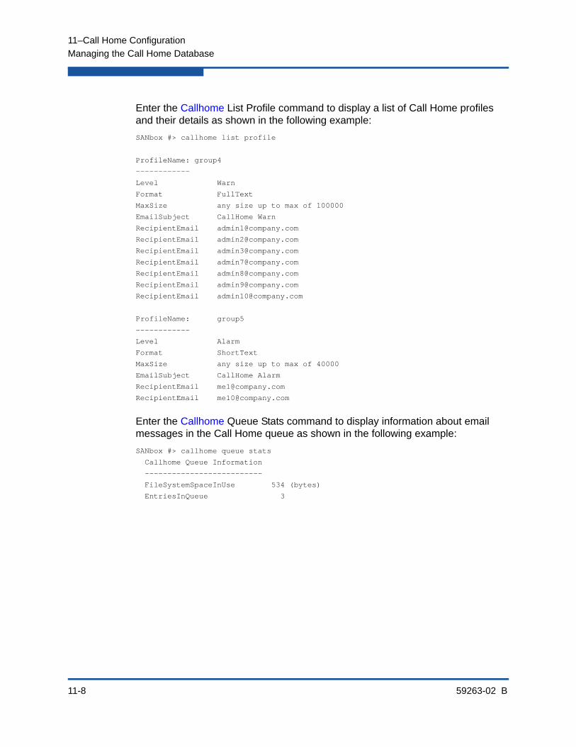
11–Call Home Configuration
Managing the Call Home Database
11-8 59263-02 B
Enter the Callhome List Profile command to display a list of Call Home profiles and their details as shown in the following example:
SANbox #> callhome list profile
ProfileName: group4
------------
Level Warn
Format FullText
MaxSize any size up to max of 100000
EmailSubject CallHome Warn
RecipientEmail [email protected]
RecipientEmail [email protected]
RecipientEmail [email protected]
RecipientEmail [email protected]
RecipientEmail [email protected]
RecipientEmail [email protected]
RecipientEmail [email protected]
ProfileName: group5
------------
Level Alarm
Format ShortText
MaxSize any size up to max of 40000
EmailSubject CallHome Alarm
RecipientEmail [email protected]
RecipientEmail [email protected]
Enter the Callhome Queue Stats command to display information about email messages in the Call Home queue as shown in the following example:
SANbox #> callhome queue stats
Callhome Queue Information
--------------------------
FileSystemSpaceInUse 534 (bytes)
EntriesInQueue 3

11–Call Home Configuration
Managing the Call Home Database
59263-02 B 11-9
Creating a ProfileEnter the Profile Create command to create a Call Home profile as shown in the following example:
SANbox #> admin start
SANbox (admin) #> callhome edit
SANbox (admin-callhome) #> profile create profile_1
A list of attributes with formatting and default values will follow.Enter a new value or simply press the ENTER key to accept the current value.If you wish to terminate this process before reaching the end of the listpress ’q’ or ’Q’ and the ENTER key to do so.
Default Values:
Level Alarm
Format FullText
MaxSize 100000
EmailSubject <undefined>
RecipientEmail (up to 10 entries allowed)
New Value (press ENTER to accept default value, 'q' to quit):
Level (Alarm,Critical,Warn,None) :
Format (1=FullText, 2=ShortText, 3=Tsc1) :
MaxSize (decimal value, 650-100000) :
EmailSubject (string, max=64 chars, N=None) : Technical problem
RecipientEmail (ex: [email protected], N=None)
1. <undefined> : [email protected]
The profile has been created.This configuration must be saved with the callhome save commandbefore it can take effect, or to discard this configurationuse the callhome cancel command.
SANbox (admin-callhome) #> callhome save
The CallHome database profiles will be saved and activated.
Please confirm (y/n): [n] y
Deleting a ProfileEnter the Profile Delete command to delete a Call Home profile as shown in the following example:
SANbox #> admin start
SANbox (admin) #> callhome edit
SANbox (admin-callhome) #> profile delete profile_1
The profile will be deleted. Please confirm (y/n): [n] y
SANbox (admin-callhome) #> callhome save
The CallHome database profiles will be saved and activated.
Please confirm (y/n): [n] y

11–Call Home Configuration
Managing the Call Home Database
11-10 59263-02 B
Modifying a ProfileEnter the Profile Edit command to modify an existing Call Home profile as shown in the following example:
SANbox #> admin start
SANbox (admin) #> callhome edit
SANbox (admin-callhome) #> profile edit profile_1
A list of attributes with formatting and current values will follow.
Enter a new value or simply press the ENTER key to accept the current value.
If you wish to terminate this process before reaching the end of the list
press 'q' or 'Q' and the ENTER key to do so.
Current Values:
Level Alarm
Format ShortText
MaxSize 1000
EmailSubject Switch Problem
RecipientEmail (up to 10 entries allowed)
New Value (press ENTER to accept current value, 'q' to quit):
Level (Alarm,Critical,Warn,None) :
Format (1=FullText, 2=ShortText, 3=Tsc1) : 1
MaxSize (decimal value, 650-100000) :
EmailSubject (string, max=64 chars, N=None) :
RecipientEmail (ex: [email protected], N=None)
1. [email protected] :
2. <undefined> :
The profile has been edited.
This configuration must be saved with the 'callhome save' command
before it can take effect, or to discard this configuration
use the 'callhome cancel' command.
SANbox (admin-callhome) #> callhome save
The CallHome database profiles will be saved and activated.
Please confirm (y/n): [n] y

11–Call Home Configuration
Managing the Call Home Database
59263-02 B 11-11
Renaming a ProfileEnter the Profile Rename command to rename profile_1 as shown in the following example:
SANbox #> admin start
SANbox (admin) #> callhome edit
SANbox (admin-callhome) #> profile rename profile_1 profile_4
The profile will be renamed. Please confirm (y/n): [n] y
SANbox (admin-callhome) #> callhome save
The CallHome database profiles will be saved and activated.
Please confirm (y/n): [n] y
Copying a ProfileEnter the Profile Copy command to copy profile_1 as shown in the following example:
SANbox #> admin start
SANbox (admin) #> callhome edit
SANbox (admin-callhome) #> profile copy profile_1 profile_a
SANbox (admin-callhome) #> callhome save
The CallHome database profiles will be saved and activated.
Please confirm (y/n): [n] y
Adding a Data Capture ConfigurationEnter the Capture Add command to add a data capture configuration to the Tech_Support_Center profile as shown in the following example. If the Tech_Support_Center profile does not exist, you must create it using the Profile Create command.
SANbox #> admin start
SANbox (admin) #> callhome edit
SANbox (admin-callhome) #> capture add
A list of attributes with formatting and default values will follow. Enter a value or simply press the ENTER key to accept the default value. If you wish to terminate this process before reaching the end of the list press 'q' or 'Q' and the ENTER key to do so.
Value (press ENTER to accept the default, 'q' to quit):
TimeOfDay (HH:MM) [02:00]
DayOfWeek (Sun,Mon,Tue,Wed,Thu,Fri,Sat) [Sat ]
Interval (decimal value, 1-26 weeks) [1 ]
A capture entry has been added to profile Tech_Support_Center. This configuration must be saved with the 'callhome save' command before it can take effect, or to discard this configuration use the 'callhome cancel' command.

11–Call Home Configuration
Managing the Call Home Database
11-12 59263-02 B
Modifying a Data Capture ConfigurationEnter the Capture Edit command to modify a data capture configuration in the Tech_Support_Center profile as shown in the following example:
SANbox #> admin start
SANbox (admin) #> callhome edit
SANbox (admin-callhome) #> capture edit
Capture Entries for Profile: Tech_Support_Center
Index TimeOfDay DayOfWeek Interval
----- --------- --------- --------
1 02:00 Sat 1 (weeks)
Please select a capture entry from the list above ('q' to quit): 1
A list of attributes with formatting and current values will follow.
Enter a value or simply press the ENTER key to accept the current value.
If you wish to terminate this process before reaching the end of the list
press 'q' or 'Q' and the ENTER key to do so.
Value (press ENTER to accept the default, 'q' to quit):
TimeOfDay (HH:MM) [02:00]
DayOfWeek (Sun,Mon,Tue,Wed,Thu,Fri,Sat) [Sat ]
Interval (decimal value, 1-26 weeks) [1 ]
The selected capture entry has been edited for profile Tech_Support_Center.
This configuration must be saved with the 'callhome save' command
before it can take effect, or to discard this configuration
use the 'callhome cancel' command.
Deleting a Data Capture ConfigurationEnter the Capture Remove command to delete a data capture configuration from the Tech_Support_Center profile as shown in the following example:
SANbox #> admin start
SANbox (admin) #> callhome edit
SANbox (admin-callhome) #> capture remove
Capture Entries for Profile: Tech_Support_Center
Index TimeOfDay DayOfWeek Interval
----- --------- --------- --------
1 02:00 Sat 1 (weeks)
Please select a capture entry from the list above ('q' to quit): 1
The selected capture entry has been removed from profile Tech_Support_Center.
This configuration must be saved with the 'callhome save' command
before it can take effect, or to discard this configuration
use the 'callhome cancel' command.
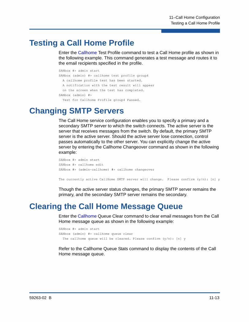
11–Call Home Configuration
Testing a Call Home Profile
59263-02 B 11-13
Testing a Call Home ProfileEnter the Callhome Test Profile command to test a Call Home profile as shown in the following example. This command generates a test message and routes it to the email recipients specified in the profile.
SANbox #> admin start
SANbox (admin) #> callhome test profile group4
A callhome profile test has been started.
A notification with the test result will appear
on the screen when the test has completed.
SANbox (admin) #>
Test for Callhome Profile group4 Passed.
Changing SMTP ServersThe Call Home service configuration enables you to specify a primary and a secondary SMTP server to which the switch connects. The active server is the server that receives messages from the switch. By default, the primary SMTP server is the active server. Should the active server lose connection, control passes automatically to the other server. You can explicitly change the active server by entering the Callhome Changeover command as shown in the following example:
SANbox #> admin start
SANbox #> callhome edit
SANbox #> (admin-callhome) #> callhome changeover
The currently active CallHome SMTP server will change. Please confirm (y/n): [n] y
Though the active server status changes, the primary SMTP server remains the primary, and the secondary SMTP server remains the secondary.
Clearing the Call Home Message QueueEnter the Callhome Queue Clear command to clear email messages from the Call Home message queue as shown in the following example:
SANbox #> admin start
SANbox (admin) #> callhome queue clear
The callhome queue will be cleared. Please confirm (y/n): [n] y
Refer to the Callhome Queue Stats command to display the contents of the Call Home message queue.
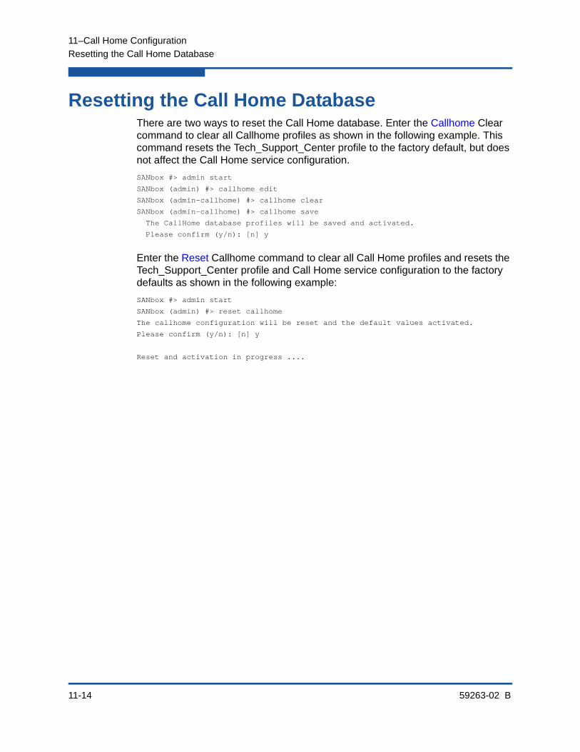
11–Call Home Configuration
Resetting the Call Home Database
11-14 59263-02 B
Resetting the Call Home DatabaseThere are two ways to reset the Call Home database. Enter the Callhome Clear command to clear all Callhome profiles as shown in the following example. This command resets the Tech_Support_Center profile to the factory default, but does not affect the Call Home service configuration.
SANbox #> admin start
SANbox (admin) #> callhome edit
SANbox (admin-callhome) #> callhome clear
SANbox (admin-callhome) #> callhome save
The CallHome database profiles will be saved and activated.
Please confirm (y/n): [n] y
Enter the Reset Callhome command to clear all Call Home profiles and resets the Tech_Support_Center profile and Call Home service configuration to the factory defaults as shown in the following example:
SANbox #> admin start
SANbox (admin) #> reset callhome
The callhome configuration will be reset and the default values activated.
Please confirm (y/n): [n] y
Reset and activation in progress ....

59263-02 B 12-1
12 Simple Network Management Protocol Configuration
This section describes the following tasks:
Managing the SNMP Service
Displaying SNMP Information
Modifying the SNMP Configuration
Resetting the SNMP Configuration
Managing the SNMP Version 3 Configuration
The Simple Network Management Protocol (SNMP) provides for the management of the switch through third-party applications that use SNMP. Security consists of a read community string and a write community string that serve as passwords that control read and write access to the switch. These strings are set at the factory to well-known defaults and should be changed if SNMP is to be enabled. The switch supports SNMP version 3 in the CLI, which is disabled by default.

12–Simple Network Management Protocol Configuration
Managing the SNMP Service
12-2 59263-02 B
Managing the SNMP ServiceYou control the SNMP service SNMPEnabled parameters through the Set Setup SNMP or Set Setup Services commands. Refer to “Modifying the SNMP Configuration” on page 12-4 for more information.
Enter the Set Setup Services command to enable SNMP as shown in the following example:
SANbox #> admin start
SANbox (admin) #> set setup services
A list of attributes with formatting and current values will follow.
Enter a new value or simply press the ENTER key to accept the current value.
If you wish to terminate this process before reaching the end of the list
press 'q' or 'Q' and the ENTER key to do so.
PLEASE NOTE:
-----------
* Further configuration may be required after enabling a service.
* If services are disabled, the connection to the switch may be lost.
* When enabling SSL, please verify that the date/time settings
on this switch and the workstation from where the SSL connection
will be started match, and then a new certificate may need to be
created to ensure a secure connection to this switch.
TelnetEnabled (True / False) [True ]
SSHEnabled (True / False) [False]
GUIMgmtEnabled (True / False) [True ]
SSLEnabled (True / False) [False]
EmbeddedGUIEnabled (True / False) [True ]
SNMPEnabled (True / False) [True ]
NTPEnabled (True / False) [False]
CIMEnabled (True / False) [False]
FTPEnabled (True / False) [True ]
MgmtServerEnabled (True / False) [True ]
CallHomeEnabled (True / False) [True ]
Do you want to save and activate this services setup? (y/n): [n]
You can display the SNMPEnabled parameters using the Show Setup Snmp or Show Setup Services commands.
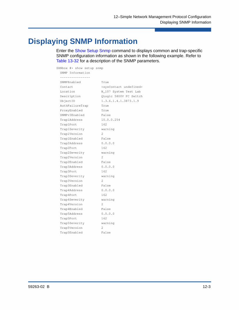
12–Simple Network Management Protocol Configuration
Displaying SNMP Information
59263-02 B 12-3
Displaying SNMP InformationEnter the Show Setup Snmp command to displays common and trap-specific SNMP configuration information as shown in the following example. Refer to Table 13-32 for a description of the SNMP parameters.
SANbox #> show setup snmp
SNMP Information
----------------
SNMPEnabled True
Contact <sysContact undefined>
Location N_107 System Test Lab
Description QLogic 5800V FC Switch
ObjectID 1.3.6.1.4.1.3873.1.9
AuthFailureTrap True
ProxyEnabled True
SNMPv3Enabled False
Trap1Address 10.0.0.254
Trap1Port 162
Trap1Severity warning
Trap1Version 2
Trap1Enabled False
Trap2Address 0.0.0.0
Trap2Port 162
Trap2Severity warning
Trap2Version 2
Trap2Enabled False
Trap3Address 0.0.0.0
Trap3Port 162
Trap3Severity warning
Trap3Version 2
Trap3Enabled False
Trap4Address 0.0.0.0
Trap4Port 162
Trap4Severity warning
Trap4Version 2
Trap4Enabled False
Trap5Address 0.0.0.0
Trap5Port 162
Trap5Severity warning
Trap5Version 2
Trap5Enabled False

12–Simple Network Management Protocol Configuration
Modifying the SNMP Configuration
12-4 59263-02 B
Modifying the SNMP ConfigurationEnter the Set Setup SNMP command in an Admin session to configure SNMP on the switch. There are two groups of configuration parameters. One group is common to all traps. The second group is trap specific. You can configure both groups of parameters for all SNMP traps, or you can configure the common and trap-specific parameters separately. Refer to Table 13-32 for descriptions of the common and trap-specific SNMP parameters.
The following example configures the common SNMP trap configuration parameters:
SANbox (admin) #> set setup snmp common
A list of attributes with formatting and current values will follow.
Enter a new value or simply press the ENTER key to accept the current value.
If you wish to terminate this process before reaching the end of the list
press 'q' or 'Q' and the ENTER key to do so.
Current Values:
SnmpEnabled True
Contact <sysContact undefined>
Location <sysLocation undefined>
ReadCommunity public
WriteCommunity private
AuthFailureTrap False
ProxyEnabled True
SNMPv3Enabled False
New Value (press ENTER to not specify value, 'q' to quit):
SnmpEnabled (True / False) :
Contact (string, max=64 chars) :
Location (string, max=64 chars) :
ReadCommunity (string, max=32 chars) :
WriteCommunity (string, max=32 chars) :
AuthFailureTrap (True / False) :
ProxyEnabled (True / False) :
SNMPv3Enabled (True / False) :
Do you want to save and activate this snmp setup? (y/n): [n]
The following example configures SNMP trap 1:
SANbox (admin) #> set setup snmp trap 1
A list of attributes with formatting and current values will follow.
Enter a new value or simply press the ENTER key to accept the current value.
If you wish to terminate this process before reaching the end of the list
press 'q' or 'Q' and the ENTER key to do so.
Current Values:
Trap1Enabled True

12–Simple Network Management Protocol Configuration
Resetting the SNMP Configuration
59263-02 B 12-5
Trap1Address 10.20.33.181
Trap1Port 5001
Trap1Severity info
Trap1Version 2
Trap1Community northdakota
New Value (press ENTER to not specify value, 'q' to quit):
Trap1Enabled (True / False) :
Trap1Address (hostname, IPv4, or IPv6 Address) :
Trap1Port (decimal value, 1-65535) :
Trap1Severity (select a severity level)
1=unknown 6=warning
2=emergency 7=notify
3=alert 8=info
4=critical 9=debug
5=error 10=mark :
Trap1Version (1 / 2) :
Trap1Community (string, max=32 chars) :
Do you want to save and activate this snmp setup? (y/n): [n]
Resetting the SNMP ConfigurationEnter the Reset SNMP command in an Admin session to reset the SNMP configuration back to the factory defaults as shown in the following example. Refer to Table 13-16 for a listing of the SNMP configuration factory defaults.
SANbox (admin) #> reset snmp

12–Simple Network Management Protocol Configuration
Managing the SNMP Version 3 Configuration
12-6 59263-02 B
Managing the SNMP Version 3 ConfigurationSNMP version 3 is an interoperable standards-based protocol for network management. SNMP version 3 provides secure access to devices by a combination of packet authentication and encryption over the network. SNMP version 3 provides the following security features:
Message integrity—ensures that packets have not been altered
Authentication—ensures that the packet is coming from a valid source
Encryption—ensures that packet contents cannot be read by an unauthorized source
To configure SNMP version 3, you must enable SNMP version 3 on the switch and create one or more SNMP version 3 user accounts. To enable SNMP version 3, enter the Set Setup SNMP Common command and set the SNMPv3Enabled parameter to True:
SANbox #> admin start
SANbox (admin) #> set setup snmp common
A list of attributes with formatting and current values will follow.
Enter a new value or simply press the ENTER key to accept the current value.
If you wish to terminate this process before reaching the end of the list
press 'q' or 'Q' and the ENTER key to do so.
Current Values:
SnmpEnabled True
Contact <sysContact undefined>
Location <sysLocation undefined>
ReadCommunity public
WriteCommunity private
AuthFailureTrap False
ProxyEnabled True
SNMPv3Enabled False
New Value (press ENTER to not specify value, 'q' to quit):
SnmpEnabled (True / False) :
Contact (string, max=64 chars) :
Location (string, max=64 chars) :
ReadCommunity (string, max=32 chars) :
WriteCommunity (string, max=32 chars) :
AuthFailureTrap (True / False) :
ProxyEnabled (True / False) :
SNMPv3Enabled (True / False) : t
Do you want to save and activate this snmp setup? (y/n): [n] y

12–Simple Network Management Protocol Configuration
Managing the SNMP Version 3 Configuration
59263-02 B 12-7
Create an SNMP Version 3 User AccountTo create an SNMP version 3 user account, enter the Snmpv3user Add command as shown in the following example:
SANbox #> admin start
SANbox (admin) #> snmpv3user add
A list of SNMPV3 user attributes with formatting and default values as
applicable will follow.
Enter a new value OR simply press the ENTER key where-ever allowed to
accept the default value.
If you wish to terminate this process before reaching the end of the list,
press "q" or "Q" and the ENTER OR "Ctrl-C" key to do so.
Username (8-32 chars) : snmpuser1
Group (0=ReadOnly, 1=ReadWrite) [ReadOnly ] : 1
Authentication (True/False) [False ] : t
AuthType (1=MD5, 2=SHA) [MD5 ] : 1
AuthPhrase (8-32 chars) : ***********
Confirm AuthPhrase : ***********
Privacy (True/False) [False ] : t
PrivType (1=DES) [DES ] : 1
PrivPhrase (8-32 chars) : ********
Confirm PrivPhrase : ********
Do you want to save and activate this snmpv3user setup ? (y/n): [n] y
SNMPV3 user added and activated.
Display SNMP Version 3 User AccountsTo display SNMP version 3 user accounts, enter the Snmpv3user List command as shown in the following example:
SANbox #> snmpv3user list
Username Group AuthType PrivType
-------- ----- -------- --------
snmpuser1 ReadWrite MD5 DES

12–Simple Network Management Protocol Configuration
Managing the SNMP Version 3 Configuration
12-8 59263-02 B
Modify an SNMP Version 3 User AccountTo modify an SNMP version 3 user account, enter the Snmpv3user Edit command as shown in the following example:
SANbox #> admin start
SANbox (admin) #> snmpv3user edit
A list of SNMPV3 user attributes with formatting and current attribute
values for the specified SNMPV3 user will follow.
Enter a new value OR simply press the ENTER key where-ever allowed to
accept the current value.
If you wish to terminate this process before reaching the end of the list,
press "q" or "Q" and the ENTER OR "Ctrl-C" key to do so.
Username (8-32 chars) : snmpuser1
Group (0=ReadOnly, 1=ReadWrite) [ReadWrite ] : 1
Authentication (True/False) [True ] : f
Do you want to save and activate this setup ? (y/n): [n] n
SNMPV3 user account edited and activated.

59263-02 B 13-1
13 Command Reference
This section describes the commands of the CLI and the format in which they are presented. The command format presents the following:
Access Authority
Syntax and Keywords
Notes and Examples
Command Listing
Access AuthorityThe Authority paragraph in each command description indicates what types of sessions are required to enter that command. Commands associated with monitoring tasks are available to all account names with no special session requirement. Commands associated with configuration tasks are available only within an Admin session. An account must have Admin authority to enter the Admin Start command, which opens an Admin session.
Some commands require that you open additional editing sessions within an Admin session such as the following:
Commands that modify zoning require a Zoning Edit session, which is opened by the Zoning Edit command. These commands include the Alias, Zone, Zoneset, and Zoning commands.
Commands that modify device security require a Security Edit session, which is opened by the Security Edit command. These commands include the Group, Security, and Securityset commands.
Commands that modify the switch configuration require a Config Edit session, which is opened by the Config Edit command. These commands include all of the Set Config commands.
Commands that modify the Call Home e-mail notification configuration require a Callhome Edit session, which is opened by the Callhome Edit command. These commands include the Callhome, Capture, and Profile commands.
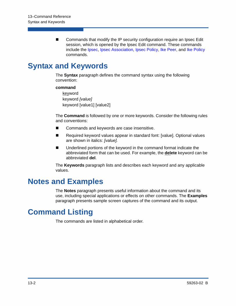
13–Command Reference
Syntax and Keywords
13-2 59263-02 B
Commands that modify the IP security configuration require an Ipsec Edit session, which is opened by the Ipsec Edit command. These commands include the Ipsec, Ipsec Association, Ipsec Policy, Ike Peer, and Ike Policy commands.
Syntax and KeywordsThe Syntax paragraph defines the command syntax using the following convention:
commandkeywordkeyword [value]keyword [value1] [value2]
The Command is followed by one or more keywords. Consider the following rules and conventions:
Commands and keywords are case insensitive.
Required keyword values appear in standard font: [value]. Optional values are shown in italics: [value].
Underlined portions of the keyword in the command format indicate the abbreviated form that can be used. For example, the delete keyword can be abbreviated del.
The Keywords paragraph lists and describes each keyword and any applicable values.
Notes and ExamplesThe Notes paragraph presents useful information about the command and its use, including special applications or effects on other commands. The Examples paragraph presents sample screen captures of the command and its output.
Command ListingThe commands are listed in alphabetical order.

13–Command Reference
Admin
59263-02 B 13-3
AdminOpens and closes an Admin session. The Admin session provides access to commands that change the fabric and switch configurations. Only one Admin session can be open on the switch at any time. An inactive Admin session will time out after a period of time which can be changed using the Set Setup System command.
Authority User account with Admin authority
Syntax adminstart (or begin)end (or stop)cancel
Keywords start (or begin)Opens the Admin session
end (or stop)Closes the Admin session. The Hardreset, Hotreset, Quit, Shutdown, and Reset Switch commands will also end an Admin session.
cancelTerminates an Admin session opened by another user. Use this keyword with care because it terminates the Admin session without warning the other user and without saving pending changes.
Notes Closing a Telnet window during an Admin session does not release the session. In this case, you must either wait for the Admin session to time out, or use the Admin Cancel command.
Examples The following example shows how to open and close an Admin session:
SANbox #> admin start
SANbox (admin) #>
.
.
.
SANbox (admin) #> admin end
13–Command Reference
Alias
13-4 59263-02 B
AliasCreates a named set of ports/devices. Aliases make it easier to assign a set of ports/devices to many zones. An alias can not have a zone or another alias as a member.
Authority Admin session and Zoning Edit session for all keywords except List and Members
Syntax aliasadd [alias] [member_list]copy [alias_source] [alias_destination]create [alias]delete [alias]listmembers [alias]remove [alias] [member_list]rename [alias_old] [alias_new]
Keywords add [alias] [member_list]
Specifies one or more ports/devices given by [member_list] to add to the alias named [alias]. Use a <space> to delimit ports/devices in [member_list]. An alias can have a maximum of 2000 members. A port/device in [member_list] can have any of the following formats:
Domain ID and port number pair (Domain ID, Port Number). Domain IDs can be 1–239; port numbers can be 0–255.
6-character hexadecimal device Fibre Channel address (hex)
16-character hexadecimal worldwide port name (WWPN) with the format xx:xx:xx:xx:xx:xx:xx:xx.
The application verifies that the [alias] format is correct, but does not validate that such a port/device exists.
copy [alias_source] [alias_destination]
Creates a new alias named [alias_destination] and copies the membership into it from the alias given by [alias_source].
create [alias]
Creates an alias with the name given by [alias]. An alias name must begin with a letter and be no longer than 64 characters. Valid characters are 0-9, A-Z, a-z, _, $, ^, and -. The zoning database supports a maximum of 256 aliases.
13–Command Reference
Alias
59263-02 B 13-5
delete [alias]
Deletes the specified alias given by [alias] from the zoning database. If the alias is a member of the active zone set, the alias will not be removed from the active zone set until the active zone set is deactivated.
list
Displays a list of all aliases. This keyword does not require an Admin session.
members [alias]
Displays all members of the alias given by [alias]. This keyword does not require an Admin session.
remove [alias] [member_list]
Removes the ports/devices given by [member_list] from the alias given by [alias]. Use a <space> to delimit ports/devices in [member_list]. A port/device in [member_list] can have any of the following formats:
Domain ID and port number pair (Domain ID, Port Number). Domain IDs can be 1–239; port numbers can be 0–255.
6-character hexadecimal device Fibre Channel address (hex)
16-character hexadecimal worldwide port name (WWPN) for the device with the format xx:xx:xx:xx:xx:xx:xx:xx.
rename [alias_old] [alias_new]
Renames the alias given by [alias_old] to the alias given by [alias_new].
Examples The following is an example of the Alias List command:
SANbox #> alias list
Current list of Zone Aliases
----------------------------
alias1
alias2

13–Command Reference
Callhome
13-6 59263-02 B
CallhomeManages the Call Home database. The Callhome Edit command opens a session in which to create and manage Call Home profiles. Refer to the Profile command for more information about Call Home profiles.
Authority Admin session except for the History and List keywords. The Clear keyword also requires a Callhome Edit session.
Syntax callhomecancelchangeoverclearedithistorylist profile [profile]queue [option]savetest profile [profile]
Keywords cancel
Closes the current Callhome Edit session. Any unsaved changes are lost.
changeover
Toggles activation between the primary SMTP server and the secondary SMTP server. Though the active server status changes, the primary SMTP server remains the primary, and the secondary SMTP server remains the secondary.
clear
Clears all Call Home profile information from the volatile edit copy of the Call Home database. This keyword requires a Callhome Edit session. This keyword does not affect the non-volatile Call Home database. However, if you enter the Callhome Clear command followed by the Callhome Save command, the non-volatile Call Home database will be cleared from the switch.
edit
Open a Callhome Edit session. Callhome Edit session commands include Callhome Clear and all Profile commands.
NOTE:
The preferred method for clearing the Call Home database from the switch is the Reset Callhome command.
13–Command Reference
Callhome
59263-02 B 13-7
history
Displays a history of Call Home modifications. This keyword does not require an Admin session. History information includes the following:
Time of the most recent Call Home database modification and the user who performed it.
Checksum for the Call Home database
Profile processing information
list profile [profile]
Lists the configuration for the profile given by [profile]. If you omit [profile], the command lists all profiles and their configurations. If you omit the profile keyword, the command lists the profile names.
queue [option]
Clears the Call Home e-mail queue or displays Call Home e-mail queue statistics depending on the value of [option]. [option] can be one of the following:
clearClears the Call Home e-mail queue.
statsDisplays Call Home e-mail queue statistics. Statistics include the number of e-mail messages in the queue and the amount of file system space in use.
save
Saves changes made during the current Callhome Edit session.
test profile [profile]
Tests the Call Home profile given by [profile].
Examples The following is an example of the Callhome History command:
SANbox #> callhome history
CallHome Database History
-------------------------
ConfigurationLastEditedBy admin@OB-session2
ConfigurationLastEditedOn day mmm dd hh:mm:ss yyyy
DatabaseChecksum 000014a3
ProfileName group4
ProfileLevel Warn
ProcessedCount 286
ProcessedLast day mmm dd hh:mm:ss yyyy
ProfileName group5
ProfileLevel Alarm
ProcessedCount 25
ProcessedLast day mmm dd hh:mm:ss yyyy

13–Command Reference
Callhome
13-8 59263-02 B
The following is an example of the Callhome List command:
SANbox #> callhome list
Configured Profiles:
--------------------
group4
group5
The following is an example of the Callhome List Profile command:
SANbox #> callhome list profile
ProfileName: group4
------------
Level Warn
Format FullText
MaxSize any size up to max of 100000
EmailSubject CallHome Warn
RecipientEmail [email protected]
RecipientEmail [email protected]
RecipientEmail [email protected]
RecipientEmail [email protected]
RecipientEmail [email protected]
RecipientEmail [email protected]
RecipientEmail [email protected]
ProfileName: group5
------------
Level Alarm
Format ShortText
MaxSize any size up to max of 40000
EmailSubject CallHome Alarm
RecipientEmail [email protected]
RecipientEmail [email protected]
The following is an example of the Callhome Test Profile command:
SANbox #> admin start
SANbox (admin) #> callhome test profile group4
A callhome profile test has been started.
A notification with the test result will appear
on the screen when the test has completed.
SANbox (admin) #>
Test for Callhome Profile group4 Passed.
13–Command Reference
Callhome
59263-02 B 13-9
The following is an example of the Callhome Queue Clear command:
SANbox #> admin start
SANbox (admin) #> callhome queue clear
The callhome queue will be cleared. Please confirm (y/n): [n] y
The following is an example of the Callhome Queue Stats command:
SANbox #> callhome queue stats
Callhome Queue Information
--------------------------
FileSystemSpaceInUse 534 (bytes)
EntriesInQueue 3

13–Command Reference
Capture
13-10 59263-02 B
CaptureManages the data capture configuration for the Tech_Support_Center Call Home profile. The data capture configuration determines the time and frequency by which status and trend data is collected from the switch and sent to recipients specified in the Tech_Support_Center profile.
Authority Admin session and a Callhome Edit session. Refer to the “Callhome” command on page 13-6 for information about starting a Callhome Edit session.
Syntax captureaddeditremove
Keywords add
Adds data capture instructions to the Tech_Support_Center profile. Table 13-1 describes the data capture parameters.
edit
Opens an edit session in which to modify the data capture configuration of the Tech_Support_Center profile. Refer to Table 13-1 for a description of the data capture configuration parameters.
removeRemoves the data capture configuration from the Test_Support_Center profile.
Table 13-1. Data Capture Configuration Parameters
Parameters Description
TimeOfDay Time of day to send status and trend data to the Tech_Support_Center profile e-mail recipients. The format is hh:mm on a 24-hour clock. The default 02:00.
DayOfWeek Day-of-the-week to send status and trend data to the Tech_Support_Center profile e-mail recipients. Values can be Sun, Mon, Tue, Wed, Thur, Fri, Sat. The default is Sat.
Interval Number of weeks between capture data e-mails to the Tech_Support_Center profile e-mail recipients. Values can be 1–26. The default is 1.
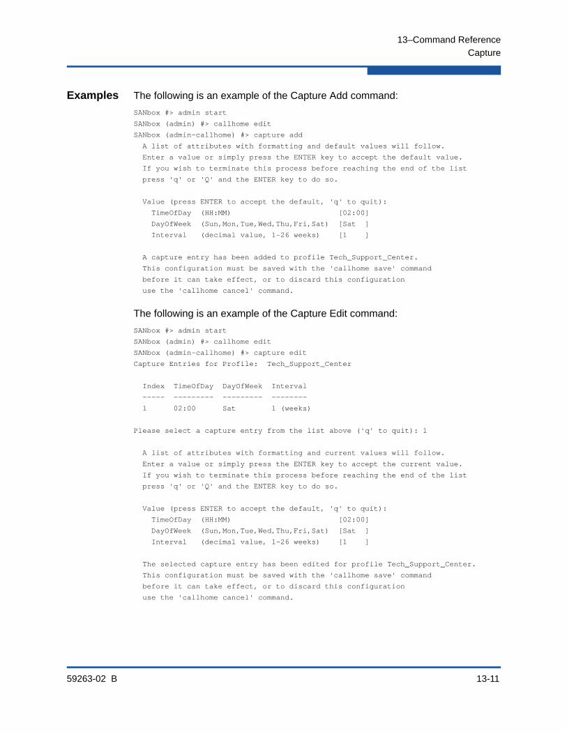
13–Command Reference
Capture
59263-02 B 13-11
Examples The following is an example of the Capture Add command:
SANbox #> admin start
SANbox (admin) #> callhome edit
SANbox (admin-callhome) #> capture add
A list of attributes with formatting and default values will follow.
Enter a value or simply press the ENTER key to accept the default value.
If you wish to terminate this process before reaching the end of the list
press 'q' or 'Q' and the ENTER key to do so.
Value (press ENTER to accept the default, 'q' to quit):
TimeOfDay (HH:MM) [02:00]
DayOfWeek (Sun,Mon,Tue,Wed,Thu,Fri,Sat) [Sat ]
Interval (decimal value, 1-26 weeks) [1 ]
A capture entry has been added to profile Tech_Support_Center.
This configuration must be saved with the 'callhome save' command
before it can take effect, or to discard this configuration
use the 'callhome cancel' command.
The following is an example of the Capture Edit command:
SANbox #> admin start
SANbox (admin) #> callhome edit
SANbox (admin-callhome) #> capture edit
Capture Entries for Profile: Tech_Support_Center
Index TimeOfDay DayOfWeek Interval
----- --------- --------- --------
1 02:00 Sat 1 (weeks)
Please select a capture entry from the list above ('q' to quit): 1
A list of attributes with formatting and current values will follow.
Enter a value or simply press the ENTER key to accept the current value.
If you wish to terminate this process before reaching the end of the list
press 'q' or 'Q' and the ENTER key to do so.
Value (press ENTER to accept the default, 'q' to quit):
TimeOfDay (HH:MM) [02:00]
DayOfWeek (Sun,Mon,Tue,Wed,Thu,Fri,Sat) [Sat ]
Interval (decimal value, 1-26 weeks) [1 ]
The selected capture entry has been edited for profile Tech_Support_Center.
This configuration must be saved with the 'callhome save' command
before it can take effect, or to discard this configuration
use the 'callhome cancel' command.
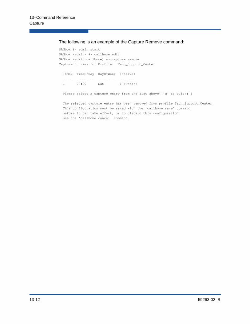
13–Command Reference
Capture
13-12 59263-02 B
The following is an example of the Capture Remove command:
SANbox #> admin start
SANbox (admin) #> callhome edit
SANbox (admin-callhome) #> capture remove
Capture Entries for Profile: Tech_Support_Center
Index TimeOfDay DayOfWeek Interval
----- --------- --------- --------
1 02:00 Sat 1 (weeks)
Please select a capture entry from the list above ('q' to quit): 1
The selected capture entry has been removed from profile Tech_Support_Center.
This configuration must be saved with the 'callhome save' command
before it can take effect, or to discard this configuration
use the 'callhome cancel' command.
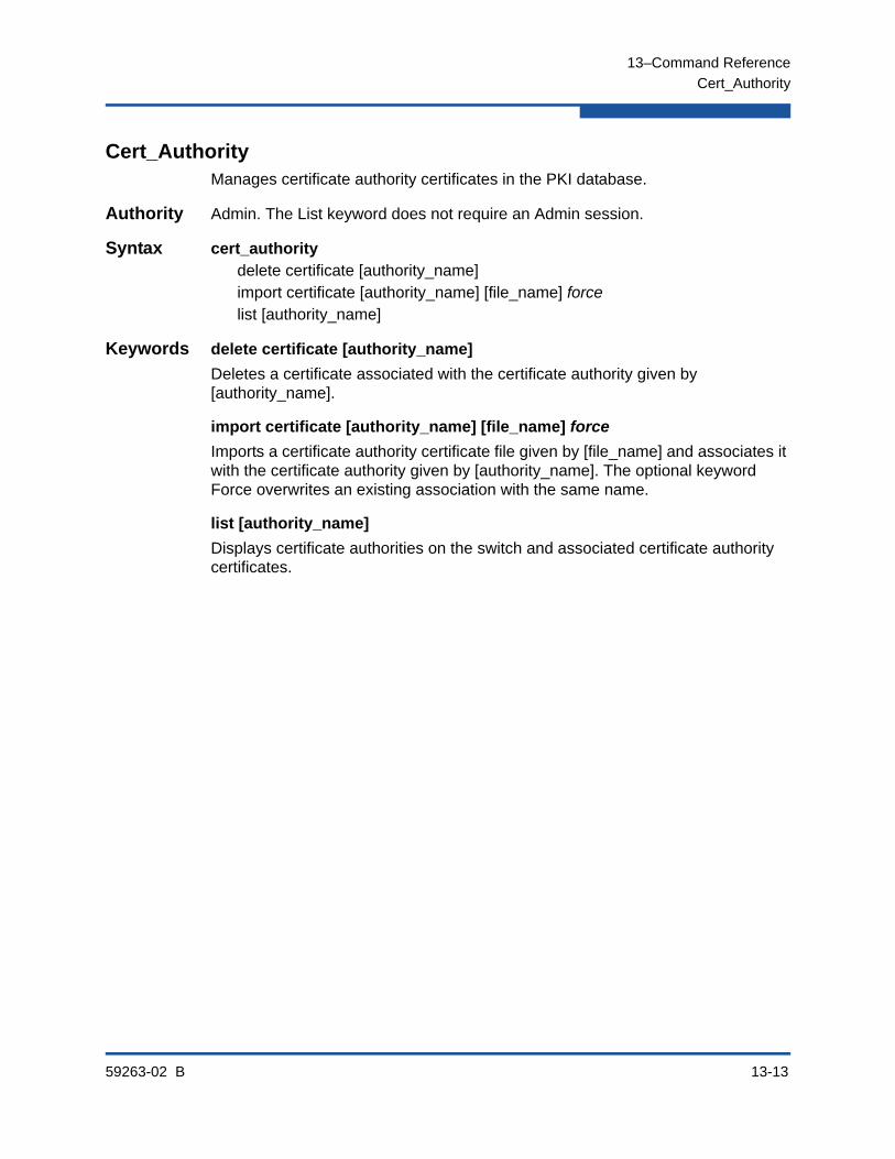
13–Command Reference
Cert_Authority
59263-02 B 13-13
Cert_AuthorityManages certificate authority certificates in the PKI database.
Authority Admin. The List keyword does not require an Admin session.
Syntax cert_authoritydelete certificate [authority_name]import certificate [authority_name] [file_name] forcelist [authority_name]
Keywords delete certificate [authority_name]
Deletes a certificate associated with the certificate authority given by [authority_name].
import certificate [authority_name] [file_name] force
Imports a certificate authority certificate file given by [file_name] and associates it with the certificate authority given by [authority_name]. The optional keyword Force overwrites an existing association with the same name.
list [authority_name]
Displays certificate authorities on the switch and associated certificate authority certificates.

13–Command Reference
Certificate
13-14 59263-02 B
CertificateCreates certificate requests and manages signed digital certificates in the PKI database.
Authority Admin
Syntax certificatedelete local [certificate_name]generate requestimport local [certificate_name] [file_name] forcelist local [certificate_name]
Keywords delete local [certificate_name]Deletes a signed certificate from the PKI database.
generate requestCreates a certificate request and stores it as a file on the switch. This keyword prompts you for the following information:
KeyName
The name of a public/private key pair.
SubjectDistinguishedName
The distinguished name for the switch.
SubjectAlternateName
One or more alternate distinguished names for the switch. These alternate names can be host names, IPv4 or IPv6 addresses, or e-mail addresses.
OutputFileName
The name of the certificate request file.
import local [certificate_name] [file_name] forceImports a signed certificate file given by [file_name] and places it in the PKI database with certificate name [certificate_name].
list local [certificate_name] Displays information about the signed certificate given by [certificate_name]. If you omit Local [certificate_name], the List keyword lists all signed certificates in the PKI database.
Notes Upload the certificate request file to your workstation and submit it to a certificate authority to obtain a signed certificate.
For information about creating a public/private key pair, see the Key command.

13–Command Reference
Certificate
59263-02 B 13-15
Examples The following is an example of a Certificate Generate Request command:
SANbox (admin) #> admin start
SANbox (admin) #> certificate generate request
A list of attributes with formatting will follow.
Enter a value or simply press the ENTER key to skip specifying a value.
If you wish to terminate this process before reaching the end of the list
press 'q' or 'Q' and the ENTER key to do so.
Required attributes are preceded by an asterisk.
*KeyName (string, max=32 chars) : key512
*SubjectDistinguishedName (string, max=128 chars) : O=Xyz
SubjectAlternateName (may enter up to 16, 1 per line)
1) enter a hostname, IPv4, IPv6 or Email Address : [email protected]
2) enter a hostname, IPv4, IPv6 or Email Address : 10.0.0.1
3) enter a hostname, IPv4, IPv6 or Email Address :
OutputFileName (string, max=64 chars) : dm5800
Certificate Request has been created and placed in file: dm5800

13–Command Reference
Clone Config Port
13-16 59263-02 B
Clone Config PortDuplicates a source port configuration on specified target ports.
Authority Admin session and a Config Edit session
Syntax clone config port[source_port_number] [port_list]
Keywords [source_port_number] [port_list]
Duplicates the configuration of a port given by [source_port_number] on a set of target ports given by [port_list]. [source_port_number] can be 0–23. [port_list] can be a list of port numbers or ranges delimited by spaces.
Notes For a description of the port configuration parameters, see Table 13-21.
Examples The following example configures ports 8–19 based on port 0:
SANbox #> admin start
SANbox (admin) config edit
SANbox (admin) #> clone config port 0 8-19
Port 0 configuration will be cloned to ports 8-19.
Please confirm (y/n): [n] y
SANbox (admin-config)#> config save
SANbox (admin)#> config activate
SANbox (admin)#> admin end

13–Command Reference
Config
59263-02 B 13-17
ConfigManages the Fibre Channel configurations on a switch. For information about setting the port and switch configurations, refer to the “Set Config Switch” command on page 13-115.
Authority Admin session for all keywords except Backup and List
Syntax configactivate [config_name]backup exportcancelcopy [config_source] [config_destination]delete [config_name]edit [config_name]export [account_name] [ip_address] [file_name]import [account_name] [ip_address] [file_name]listrestore importsave [config_name]
Keywords activate [config_name]
Activates the configuration given by [config_name]. If you omit [config_name], the currently active configuration is used. Only one configuration can be active at a time.
backup export
Creates a file named configdata, which contains the system configuration information. This keyword does not require an Admin session. Configuration backup files are deleted from the switch during a power cycle or switch reset.
The optional Export keyword creates the configuration backup file and exports it to a remote server prompting you for the server, an account name, the server IP address or DNS host name, destination file name, and a password if the server requires one.
cancel
Terminates the current configuration edit session without saving changes that were made.
copy [config_source] [config_destination]
Copies the configuration given by [config_source] to the configuration given by [config_destination]. The switch supports up to 10 configurations including the default configuration.
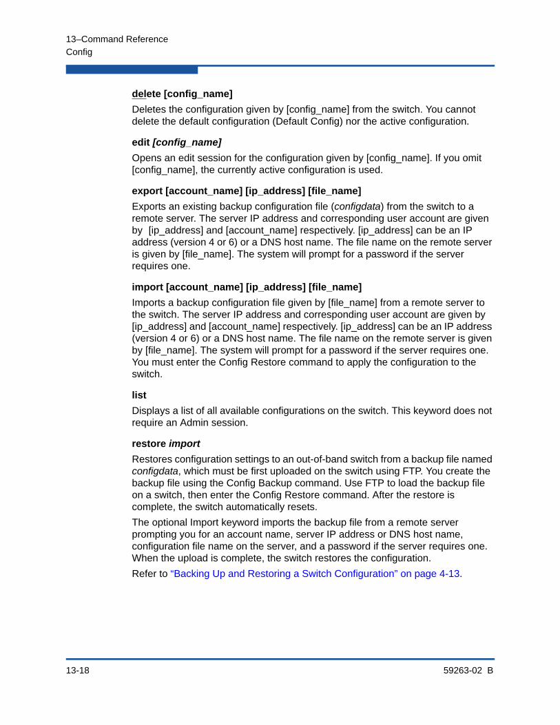
13–Command Reference
Config
13-18 59263-02 B
delete [config_name]
Deletes the configuration given by [config_name] from the switch. You cannot delete the default configuration (Default Config) nor the active configuration.
edit [config_name]
Opens an edit session for the configuration given by [config_name]. If you omit [config_name], the currently active configuration is used.
export [account_name] [ip_address] [file_name]
Exports an existing backup configuration file (configdata) from the switch to a remote server. The server IP address and corresponding user account are given by [ip_address] and [account_name] respectively. [ip_address] can be an IP address (version 4 or 6) or a DNS host name. The file name on the remote server is given by [file_name]. The system will prompt for a password if the server requires one.
import [account_name] [ip_address] [file_name]
Imports a backup configuration file given by [file_name] from a remote server to the switch. The server IP address and corresponding user account are given by [ip_address] and [account_name] respectively. [ip_address] can be an IP address (version 4 or 6) or a DNS host name. The file name on the remote server is given by [file_name]. The system will prompt for a password if the server requires one. You must enter the Config Restore command to apply the configuration to the switch.
list
Displays a list of all available configurations on the switch. This keyword does not require an Admin session.
restore import
Restores configuration settings to an out-of-band switch from a backup file named configdata, which must be first uploaded on the switch using FTP. You create the backup file using the Config Backup command. Use FTP to load the backup file on a switch, then enter the Config Restore command. After the restore is complete, the switch automatically resets.
The optional Import keyword imports the backup file from a remote server prompting you for an account name, server IP address or DNS host name, configuration file name on the server, and a password if the server requires one. When the upload is complete, the switch restores the configuration.
Refer to “Backing Up and Restoring a Switch Configuration” on page 4-13.

13–Command Reference
Config
59263-02 B 13-19
save [config_name]
Saves changes made during a configuration edit session in the configuration given by [config_name]. If you omit [config_name], the value for [config_name] you chose for the most recent Config Edit command is used. [config_name] can be up to 31 characters excluding #, semicolon (;), and comma (,). The switch supports up to 10 configurations including the default configuration.
Notes Changes you make to an active or inactive configuration can be saved, but will not take effect until you activate that configuration.
Examples The following shows an example of how to open and close a Config Edit session:
SANbox #> admin start
SANbox (admin) #> config edit
The config named default is being edited.
.
.
SANbox (admin-config) #> config cancel
Configuration mode will be canceled. Please confirm (y/n): [n] y SANbox (admin) #> admin end
NOTE:
If the restore process changes the IP address, use the Set Setup System command to return the IP configuration to the values you want. If the IP address is unknown, you must place the switch in maintenance mode and reset the network configuration to restore the default IP address 10.0.0.1. Refer to the installation guide for information about using maintenance mode.
Configuration archive files created with the Enterprise Fabric Suite Archive function are not compatible with the Config Restore command.
The configdata backup file does not include the security group primary or secondary secrets, and therefore are not restored. You must edit the security database and reconfigure the secrets. If they are not, the switch will isolate from the fabric.

13–Command Reference
Config
13-20 59263-02 B
The following is an example of how to create a backup file (configdata) and download the file to the workstation.
SANbox #> config backup
SANbox #> exit
#>ftp symbolic_name or ip_address
user: images
password: images
ftp> bin
ftp> get configdata
ftp> quit
The following is an example of how to upload a configuration backup file (configdata) from the workstation to the switch, and then restore the configuration.
#> ftp symbolic_name or ip_address
user: images
password: images
ftp> bin
ftp> put configdata
ftp> quit
SANbox #> admin start
SANbox (admin) #> config restore
The switch will be reset after restoring the configuration.
Please confirm (y/n): [n] y
Alarm Msg: [day month date time year][A1005.0021][SM][Configuration is being restored - this could take several minutes]
Alarm Msg: [day month date time year][A1000.000A][SM][The switch will be reset in 3 seconds due to a config restore]
SANbox (admin) #>
Alarm Msg: [day month date time year][A1000.0005][SM][The switch is being reset]

13–Command Reference
Create
59263-02 B 13-21
CreateCreates support files for troubleshooting switch problems, and certificates for secure communications for Enterprise Fabric Suite and SMI-S.
Authority Admin session for the Certificate keyword
Syntax createcertificatesupport
Keywords certificate
Creates a security certificate on the switch. The security certificate is required to establish an SSL connection with a management application such as Enterprise Fabric Suite. The certificate is valid 24 hours before the certificate creation date and expires 365 days after the creation date. Should the current certificate become invalid, use the Create Certificate command to create a new one.
support
Assembles all log files and switch memory data into a file (dump_support.tgz) on the switch. If your workstation has an FTP server, you can proceed with the command prompts to send the file from the switch to a remote host. Otherwise, you can use FTP to download the support file from the switch to your workstation. The support file is useful to technical support personnel for troubleshooting switch problems. Use this command when directed by your authorized maintenance provider. This keyword does not require an Admin session.
NOTE:
To insure the creation of a valid certificate, be sure that the switch and the workstation time and date are the same. Refer to the following commands:
“Date” command on page 13-24 for information about setting the time and date
“Set Timezone” command on page 13-151 for information about setting the time zone on the switch and workstation
“Set Setup System” command on page 13-142 (System keyword) for information about enabling the Network Time Protocol for synchronizing the time and date on the switch and workstation from an NTP server.
NOTE:
Support files are deleted from the switch during a power cycle or switch reset.
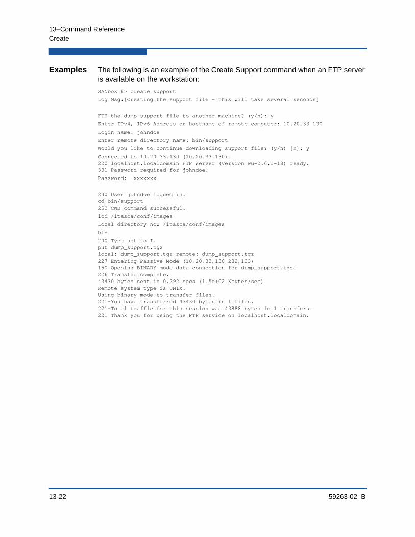
13–Command Reference
Create
13-22 59263-02 B
Examples The following is an example of the Create Support command when an FTP server is available on the workstation:
SANbox #> create support
Log Msg:[Creating the support file - this will take several seconds]
FTP the dump support file to another machine? (y/n): y
Enter IPv4, IPv6 Address or hostname of remote computer: 10.20.33.130
Login name: johndoe
Enter remote directory name: bin/support
Would you like to continue downloading support file? (y/n) [n]: y
Connected to 10.20.33.130 (10.20.33.130).220 localhost.localdomain FTP server (Version wu-2.6.1-18) ready.331 Password required for johndoe.
Password: xxxxxxx
230 User johndoe logged in.cd bin/support250 CWD command successful.
lcd /itasca/conf/images
Local directory now /itasca/conf/images
bin
200 Type set to I.put dump_support.tgzlocal: dump_support.tgz remote: dump_support.tgz227 Entering Passive Mode (10,20,33,130,232,133)150 Opening BINARY mode data connection for dump_support.tgz.226 Transfer complete.43430 bytes sent in 0.292 secs (1.5e+02 Kbytes/sec)Remote system type is UNIX.Using binary mode to transfer files.221-You have transferred 43430 bytes in 1 files.221-Total traffic for this session was 43888 bytes in 1 transfers.221 Thank you for using the FTP service on localhost.localdomain.

13–Command Reference
Create
59263-02 B 13-23
The following is an example of the Create Support command to download the support file to your workstation. When prompted to send the support file to another machine, you decline, close the Telnet session, and open an FTP session on the switch and log in with the account name images and password images. You then use the Get FTP command to transfer the dump_support.tgz file in binary mode.
SANbox #> create support
SANbox (admin) #> create support
Log Msg:[Creating the support file - this will take several seconds]
FTP the dump support file to another machine? (y/n): n
SANbox (admin) #> quit
>ftp switch_ip_address
user: images
password: images
ftp>bin
ftp>get dump_support.tgz
xxxxx bytes sent in xx secs.
ftp> quit
The following is an example of the Create Certificate command:
SANbox (admin) #> create certificate
The current date and time is day mon date hh:mm:ss UTC yyyy.
This is the time used to stamp onto the certificate.
Is the date and time correct? (y/n): [n] y
Certificate generation successful.
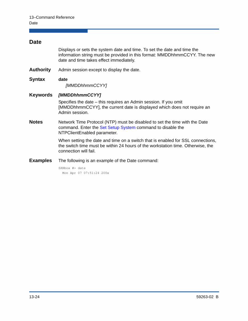
13–Command Reference
Date
13-24 59263-02 B
DateDisplays or sets the system date and time. To set the date and time the information string must be provided in this format: MMDDhhmmCCYY. The new date and time takes effect immediately.
Authority Admin session except to display the date.
Syntax date[MMDDhhmmCCYY]
Keywords [MMDDhhmmCCYY]
Specifies the date – this requires an Admin session. If you omit [MMDDhhmmCCYY], the current date is displayed which does not require an Admin session.
Notes Network Time Protocol (NTP) must be disabled to set the time with the Date command. Enter the Set Setup System command to disable the NTPClientEnabled parameter.
When setting the date and time on a switch that is enabled for SSL connections, the switch time must be within 24 hours of the workstation time. Otherwise, the connection will fail.
Examples The following is an example of the Date command:
SANbox #> date
Mon Apr 07 07:51:24 200x
13–Command Reference
Exit
59263-02 B 13-25
ExitCloses the Telnet session.
Authority None
Syntax exit
Notes You can also press Control-D to close the Telnet session.

13–Command Reference
Fcping
13-26 59263-02 B
FcpingVerifies a Fibre Channel connection with another switch or a device and reports status.
Authority None
Syntax fcping destination [address]count [number]timeout [seconds]
Keywords [address]
The address of the port or device with which to verify the Fibre Channel connection. [address] can have one of the following formats:
6-character hexadecimal device Fibre Channel address (hex). Enter addresses with or without the “0x” prefix.
16-character hexadecimal worldwide port name (WWPN) with the format xx:xx:xx:xx:xx:xx:xx:xx or xxxxxxxxxxxxxxxx.
count [number]
Number of times given by [number] to repeat the command. If you omit this keyword, the command is repeated once.
timeout [seconds]
Number of seconds given by [seconds] to wait for a response. If you omit this keyword, the switch waits 1 second for a response.
Examples The following is an example of the Fcping command:
SANbox #> fcping 970400 count 3
28 bytes from local switch to 0x970400 time = 10 usec
28 bytes from local switch to 0x970400 time = 11 usec
28 bytes from local switch to 0x970400 time = 119 usec
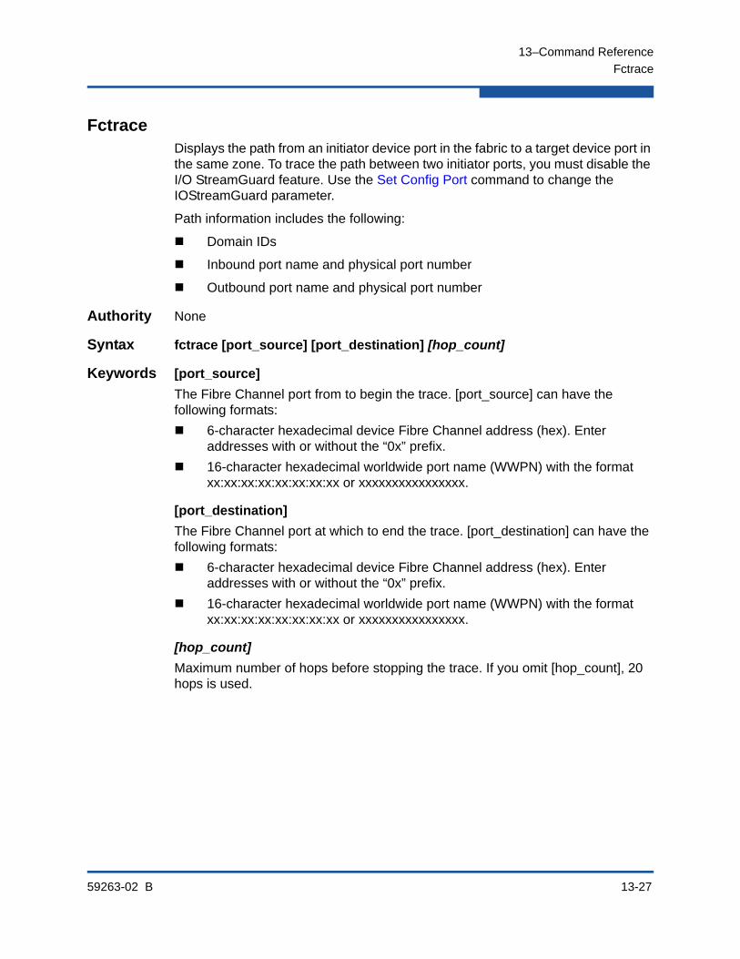
13–Command Reference
Fctrace
59263-02 B 13-27
FctraceDisplays the path from an initiator device port in the fabric to a target device port in the same zone. To trace the path between two initiator ports, you must disable the I/O StreamGuard feature. Use the Set Config Port command to change the IOStreamGuard parameter.
Path information includes the following:
Domain IDs
Inbound port name and physical port number
Outbound port name and physical port number
Authority None
Syntax fctrace [port_source] [port_destination] [hop_count]
Keywords [port_source]
The Fibre Channel port from to begin the trace. [port_source] can have the following formats:
6-character hexadecimal device Fibre Channel address (hex). Enter addresses with or without the “0x” prefix.
16-character hexadecimal worldwide port name (WWPN) with the format xx:xx:xx:xx:xx:xx:xx:xx or xxxxxxxxxxxxxxxx.
[port_destination]
The Fibre Channel port at which to end the trace. [port_destination] can have the following formats:
6-character hexadecimal device Fibre Channel address (hex). Enter addresses with or without the “0x” prefix.
16-character hexadecimal worldwide port name (WWPN) with the format xx:xx:xx:xx:xx:xx:xx:xx or xxxxxxxxxxxxxxxx.
[hop_count]
Maximum number of hops before stopping the trace. If you omit [hop_count], 20 hops is used.

13–Command Reference
Fctrace
13-28 59263-02 B
Examples The following is an example of the Fctrace command:
SANbox#> fctrace 970400 970e00 hops 5
36 bytes from 0x970400 to 0x970e00, 5 hops max
Domain Ingress Port WWN Port Egress Port WWN Port
------ ---------------- ---- --------------- ----
97 20:04:00:c0:dd:02:cc:2e 4 20:0e:00:c0:dd:02:cc:2e 14
97 20:0e:00:c0:dd:02:cc:2e 14 20:04:00:c0:dd:02:cc:2e 4

13–Command Reference
Feature
59263-02 B 13-29
FeatureAdds license key features to the switch and displays the license key feature log. To order a license key, contact your switch distributor or your authorized reseller. Upgrading a switch is not disruptive, nor does it require a switch reset.
Authority Admin session for Add keyword only
Syntax featureadd [license_key]log
Keywords add [license_key]
Adds the feature that corresponds to the value given by [license_key]. [license_key] is case insensitive.
log
Displays a list of installed license key features.
Notes The following license keys are available:
Enterprise Fabric Suite is a workstation-based Java® application that provides a graphical user interface for fabric management. This includes Performance View, which graphs port performance. Enterprise Fabric Suite comes with a free 30-day trial license.
Port Activation enables additional Fibre Channel ports up to the 24-port maximum.
20Gb Activation upgrades the XPAK ports to 20Gbps.
Examples The following is an example of the Feature Add command:
SANbox #> admin start
SANbox (admin) #> feature add 1-LCVXOWUNOJBE6
License upgrade to 24 ports
Do you want to continue with license upgrade procedure? (y/n): [n] y
Alarm Msg:[day mon date time year][A1005.0030][SM][Upgrading Licensed Ports to 24]
The following is an example of the Feature Log command:
SANbox #> feature log
Mfg Feature Log: ----------------
Switch Licensed for 8 ports
Customer Feature Log: ---------------------
1) day month date 19:39:24 year - Switch Licensed for 24 ports 1-LCVXOWUNOJBE6

13–Command Reference
Firmware Install
13-30 59263-02 B
Firmware InstallDownloads firmware from a remote host to the switch, installs the firmware, then resets the switch to activate the firmware. This is disruptive. The command prompts you for the following:
The file transfer protocol (FTP or TFTP)
IP address or DNS host name of the remote host
An account name and password on the remote host (FTP only)
Pathname for the firmware image file
Authority Admin session
Syntax firmware install
Examples The following is an example of the Firmware Install command using FTP:
SANbox #> admin start
SANbox (admin) #> firmware install
The switch will be reset. This process will cause a disruption to I/O traffic.
Continuing with this action will terminate all management sessions, including any Telnet sessions. When the firmware activation is complete,
you may log in to the switch again.
Do you want to continue? [y/n]: y
Press 'q' and the ENTER key to abort this command.
FTP or TFTP : ftp
User Account : johndoe
IP Address : 10.0.0.254
Source Filename : 8.0.00.xx_epc
About to install image. Do you want to continue? [y/n] y
Connected to 10.0.0.254 (10.0.0.254).
220 localhost.localdomain FTP server (Version wu-2.6.1-18) ready.
331 Password required for johndoe.
Password: xxxxxxxxx
230 User johndoe logged in.
bin
200 Type set to I.
verbose
Verbose mode off.
This may take several seconds...
The switch will now reset.
Connection closed by foreign host.
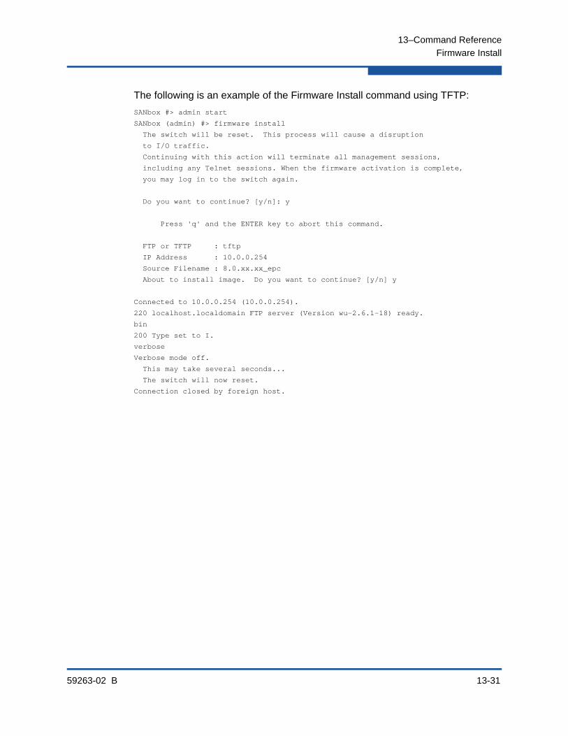
13–Command Reference
Firmware Install
59263-02 B 13-31
The following is an example of the Firmware Install command using TFTP:
SANbox #> admin start
SANbox (admin) #> firmware install
The switch will be reset. This process will cause a disruption
to I/O traffic.
Continuing with this action will terminate all management sessions,
including any Telnet sessions. When the firmware activation is complete,
you may log in to the switch again.
Do you want to continue? [y/n]: y
Press 'q' and the ENTER key to abort this command.
FTP or TFTP : tftp
IP Address : 10.0.0.254
Source Filename : 8.0.xx.xx_epc
About to install image. Do you want to continue? [y/n] y
Connected to 10.0.0.254 (10.0.0.254).
220 localhost.localdomain FTP server (Version wu-2.6.1-18) ready.
bin
200 Type set to I.
verbose
Verbose mode off.
This may take several seconds...
The switch will now reset.
Connection closed by foreign host.
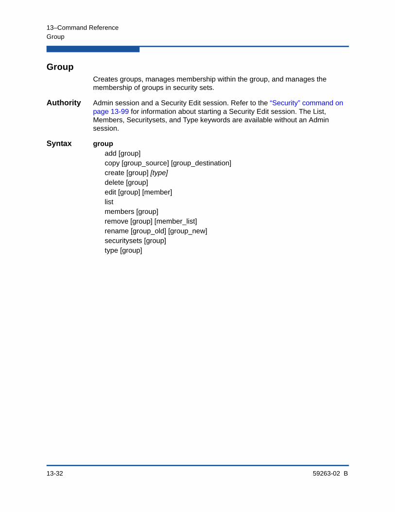
13–Command Reference
Group
13-32 59263-02 B
GroupCreates groups, manages membership within the group, and manages the membership of groups in security sets.
Authority Admin session and a Security Edit session. Refer to the “Security” command on page 13-99 for information about starting a Security Edit session. The List, Members, Securitysets, and Type keywords are available without an Admin session.
Syntax groupadd [group]copy [group_source] [group_destination]create [group] [type]delete [group]edit [group] [member]listmembers [group]remove [group] [member_list]rename [group_old] [group_new]securitysets [group]type [group]
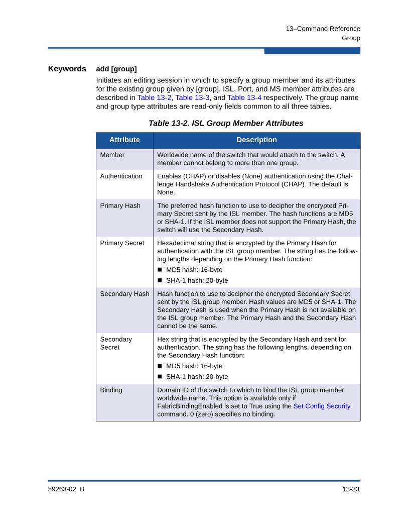
13–Command Reference
Group
59263-02 B 13-33
Keywords add [group]
Initiates an editing session in which to specify a group member and its attributes for the existing group given by [group]. ISL, Port, and MS member attributes are described in Table 13-2, Table 13-3, and Table 13-4 respectively. The group name and group type attributes are read-only fields common to all three tables.
Table 13-2. ISL Group Member Attributes
Attribute Description
Member Worldwide name of the switch that would attach to the switch. A member cannot belong to more than one group.
Authentication Enables (CHAP) or disables (None) authentication using the Chal-lenge Handshake Authentication Protocol (CHAP). The default is None.
Primary Hash The preferred hash function to use to decipher the encrypted Pri-mary Secret sent by the ISL member. The hash functions are MD5 or SHA-1. If the ISL member does not support the Primary Hash, the switch will use the Secondary Hash.
Primary Secret Hexadecimal string that is encrypted by the Primary Hash for authentication with the ISL group member. The string has the follow-ing lengths depending on the Primary Hash function:
MD5 hash: 16-byte
SHA-1 hash: 20-byte
Secondary Hash Hash function to use to decipher the encrypted Secondary Secret sent by the ISL group member. Hash values are MD5 or SHA-1. The Secondary Hash is used when the Primary Hash is not available on the ISL group member. The Primary Hash and the Secondary Hash cannot be the same.
Secondary Secret
Hex string that is encrypted by the Secondary Hash and sent for authentication. The string has the following lengths, depending on the Secondary Hash function:
MD5 hash: 16-byte
SHA-1 hash: 20-byte
Binding Domain ID of the switch to which to bind the ISL group member worldwide name. This option is available only if FabricBindingEnabled is set to True using the Set Config Security command. 0 (zero) specifies no binding.
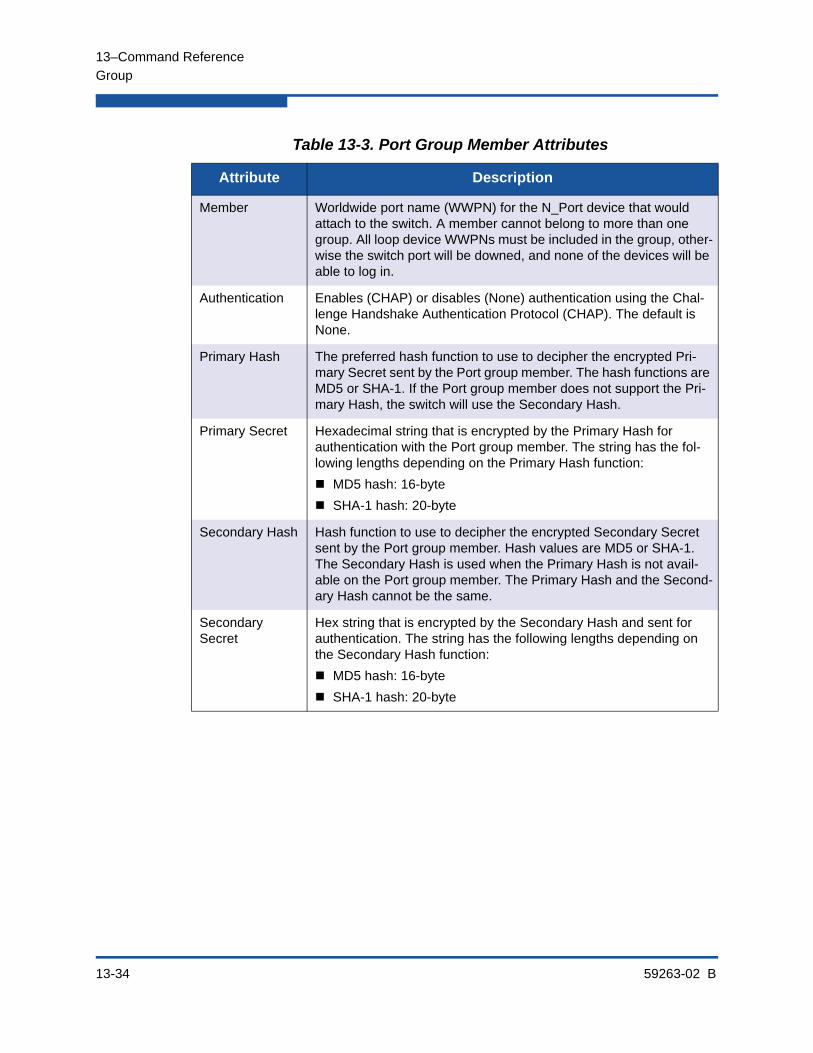
13–Command Reference
Group
13-34 59263-02 B
Table 13-3. Port Group Member Attributes
Attribute Description
Member Worldwide port name (WWPN) for the N_Port device that would attach to the switch. A member cannot belong to more than one group. All loop device WWPNs must be included in the group, other-wise the switch port will be downed, and none of the devices will be able to log in.
Authentication Enables (CHAP) or disables (None) authentication using the Chal-lenge Handshake Authentication Protocol (CHAP). The default is None.
Primary Hash The preferred hash function to use to decipher the encrypted Pri-mary Secret sent by the Port group member. The hash functions are MD5 or SHA-1. If the Port group member does not support the Pri-mary Hash, the switch will use the Secondary Hash.
Primary Secret Hexadecimal string that is encrypted by the Primary Hash for authentication with the Port group member. The string has the fol-lowing lengths depending on the Primary Hash function:
MD5 hash: 16-byte
SHA-1 hash: 20-byte
Secondary Hash Hash function to use to decipher the encrypted Secondary Secret sent by the Port group member. Hash values are MD5 or SHA-1. The Secondary Hash is used when the Primary Hash is not avail-able on the Port group member. The Primary Hash and the Second-ary Hash cannot be the same.
Secondary Secret
Hex string that is encrypted by the Secondary Hash and sent for authentication. The string has the following lengths depending on the Secondary Hash function:
MD5 hash: 16-byte
SHA-1 hash: 20-byte
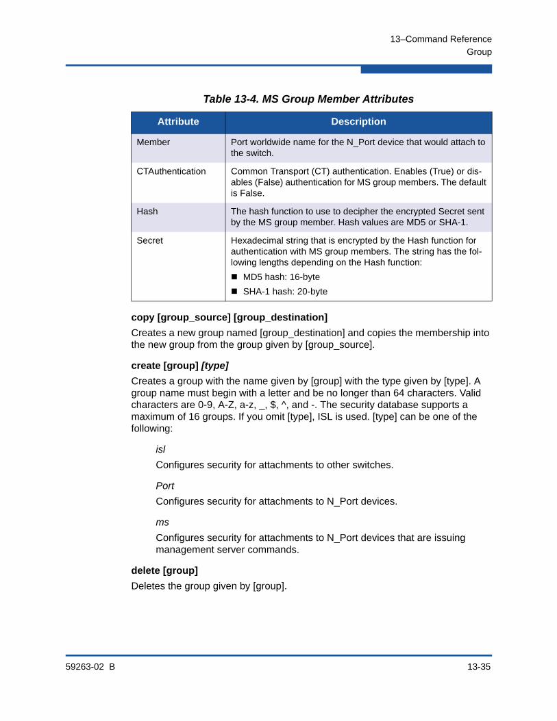
13–Command Reference
Group
59263-02 B 13-35
copy [group_source] [group_destination]
Creates a new group named [group_destination] and copies the membership into the new group from the group given by [group_source].
create [group] [type]
Creates a group with the name given by [group] with the type given by [type]. A group name must begin with a letter and be no longer than 64 characters. Valid characters are 0-9, A-Z, a-z, _, $, ^, and -. The security database supports a maximum of 16 groups. If you omit [type], ISL is used. [type] can be one of the following:
isl
Configures security for attachments to other switches.
Port
Configures security for attachments to N_Port devices.
ms
Configures security for attachments to N_Port devices that are issuing management server commands.
delete [group]
Deletes the group given by [group].
Table 13-4. MS Group Member Attributes
Attribute Description
Member Port worldwide name for the N_Port device that would attach to the switch.
CTAuthentication Common Transport (CT) authentication. Enables (True) or dis-ables (False) authentication for MS group members. The default is False.
Hash The hash function to use to decipher the encrypted Secret sent by the MS group member. Hash values are MD5 or SHA-1.
Secret Hexadecimal string that is encrypted by the Hash function for authentication with MS group members. The string has the fol-lowing lengths depending on the Hash function:
MD5 hash: 16-byte
SHA-1 hash: 20-byte
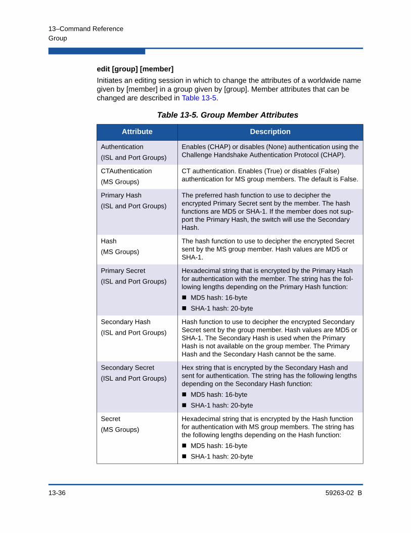
13–Command Reference
Group
13-36 59263-02 B
edit [group] [member]
Initiates an editing session in which to change the attributes of a worldwide name given by [member] in a group given by [group]. Member attributes that can be changed are described in Table 13-5.
Table 13-5. Group Member Attributes
Attribute Description
Authentication
(ISL and Port Groups)
Enables (CHAP) or disables (None) authentication using the Challenge Handshake Authentication Protocol (CHAP).
CTAuthentication
(MS Groups)
CT authentication. Enables (True) or disables (False) authentication for MS group members. The default is False.
Primary Hash
(ISL and Port Groups)
The preferred hash function to use to decipher the encrypted Primary Secret sent by the member. The hash functions are MD5 or SHA-1. If the member does not sup-port the Primary Hash, the switch will use the Secondary Hash.
Hash
(MS Groups)
The hash function to use to decipher the encrypted Secret sent by the MS group member. Hash values are MD5 or SHA-1.
Primary Secret
(ISL and Port Groups)
Hexadecimal string that is encrypted by the Primary Hash for authentication with the member. The string has the fol-lowing lengths depending on the Primary Hash function:
MD5 hash: 16-byte
SHA-1 hash: 20-byte
Secondary Hash
(ISL and Port Groups)
Hash function to use to decipher the encrypted Secondary Secret sent by the group member. Hash values are MD5 or SHA-1. The Secondary Hash is used when the Primary Hash is not available on the group member. The Primary Hash and the Secondary Hash cannot be the same.
Secondary Secret
(ISL and Port Groups)
Hex string that is encrypted by the Secondary Hash and sent for authentication. The string has the following lengths depending on the Secondary Hash function:
MD5 hash: 16-byte
SHA-1 hash: 20-byte
Secret
(MS Groups)
Hexadecimal string that is encrypted by the Hash function for authentication with MS group members. The string has the following lengths depending on the Hash function:
MD5 hash: 16-byte
SHA-1 hash: 20-byte
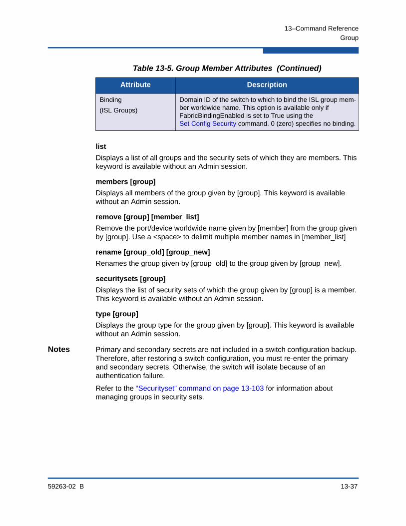
13–Command Reference
Group
59263-02 B 13-37
list
Displays a list of all groups and the security sets of which they are members. This keyword is available without an Admin session.
members [group]
Displays all members of the group given by [group]. This keyword is available without an Admin session.
remove [group] [member_list]
Remove the port/device worldwide name given by [member] from the group given by [group]. Use a <space> to delimit multiple member names in [member_list]
rename [group_old] [group_new]
Renames the group given by [group_old] to the group given by [group_new].
securitysets [group]
Displays the list of security sets of which the group given by [group] is a member. This keyword is available without an Admin session.
type [group]
Displays the group type for the group given by [group]. This keyword is available without an Admin session.
Notes Primary and secondary secrets are not included in a switch configuration backup. Therefore, after restoring a switch configuration, you must re-enter the primary and secondary secrets. Otherwise, the switch will isolate because of an authentication failure.
Refer to the “Securityset” command on page 13-103 for information about managing groups in security sets.
Binding
(ISL Groups)
Domain ID of the switch to which to bind the ISL group mem-ber worldwide name. This option is available only if FabricBindingEnabled is set to True using the Set Config Security command. 0 (zero) specifies no binding.
Table 13-5. Group Member Attributes (Continued)
Attribute Description

13–Command Reference
Group
13-38 59263-02 B
Examples The following is an example of the Group Add command:
SANbox #> admin start
SANbox (admin) #> security edit
SANbox (admin-security) #> group add Group_1
A list of attributes with formatting and default values will follow Enter a new value or simply press the ENTER key to accept the current value with exception of the Group Member WWN field which is mandatory. If you wish to terminate this process before reaching the end of the list press 'q' or 'Q' and the ENTER key to do so.
Group Name Group_1
Group Type ISL
Member (WWN) [00:00:00:00:00:00:00:00] 10:00:00:c0:dd:00:90:a3
Authentication (None / Chap) [None ] chap
PrimaryHash (MD5 / SHA-1) [MD5 ]
PrimarySecret (32 hex or 16 ASCII char value) [ ] 0123456789abcdef
SecondaryHash (MD5 / SHA-1 / None) [None ]
SecondarySecret (40 hex or 20 ASCII char value) [ ]
Binding (domain ID 1-239, 0=None) [0 ]
Finished configuring attributes. To discard this configuration use the security cancel command.
The following is an example of the Group Edit command:
SANbox #> admin start
SANbox (admin) #> security edit
SANbox (admin-security) #> group edit G1 10:00:00:c0:dd:00:90:a3 A list of attributes with formatting and current values will follow. Enter a new value or simply press the ENTER key to accept the current value. If you wish to terminate this process before reaching the end of the list press 'q' or 'Q' and the ENTER key to do so.
Group Name g1
Group Type ISL
Group Member 10:00:00:c0:dd:00:90:a3
Authentication (None / Chap) [None] chap
PrimaryHash (MD5 / SHA-1) [MD5 ] sha-1
PrimarySecret (40 hex or 20 ASCII char value) [ ] 12345678901234567890
SecondaryHash (MD5 / SHA-1 / None) [None] md5
SecondarySecret (32 hex or 16 ASCII char value) [ ] 1234567890123456
Binding (domain ID 1-239, 0=None) [3 ]
Finished configuring attributes. To discard this configuration use the security cancel command.
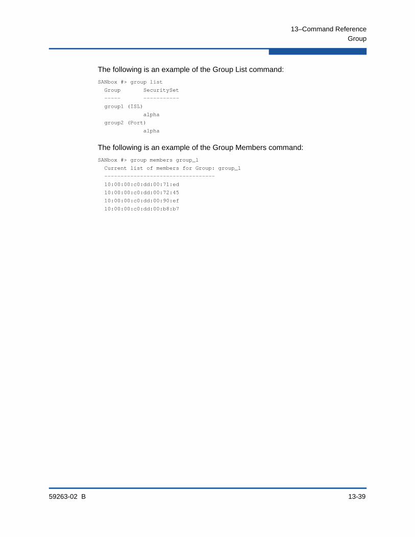
13–Command Reference
Group
59263-02 B 13-39
The following is an example of the Group List command:
SANbox #> group list
Group SecuritySet
----- -----------
group1 (ISL)
alpha
group2 (Port)
alpha
The following is an example of the Group Members command:
SANbox #> group members group_1
Current list of members for Group: group_1
----------------------------------
10:00:00:c0:dd:00:71:ed
10:00:00:c0:dd:00:72:45
10:00:00:c0:dd:00:90:ef
10:00:00:c0:dd:00:b8:b7
13–Command Reference
Hardreset
13-40 59263-02 B
HardresetResets the switch and performs a power-on self test (POST). This reset disrupts I/O traffic, activates the pending firmware, and clears the alarm log. To save the alarm log before resetting, refer to the “Set Log” on page 13-121.
Authority Admin session
Syntax hardreset
Notes To reset the switch without a power-on self test, refer to the “Reset” command on page 13-89.
To reset the switch without disrupting traffic, refer to the “Hotreset” command on page 13-43.
13–Command Reference
Help
59263-02 B 13-41
HelpDisplays a brief description of the specified command, its keywords, and usage.
Authority None
Syntax help [command] [keyword]
Keywords [command]
Displays a summary of the command given by [command] and its keywords. If you omit [command], the system displays all available commands.
[keyword]
Displays a summary of the keyword given by [keyword] belonging to the command given by [command]. If you omit [keyword], the system displays the available keywords for the specified command.
all
Displays a list of all available commands (including command variations).
Examples The following is an example of the Help Config command:
SANbox #> help config
config CONFIG_OPTIONS
The config command operates on configurations.
Usage: config { activate | backup | cancel | copy | delete |
edit | list | restore | save }
The following is an example of the Help Config Edit command:
SANbox #> help config edit
config edit [CONFIG_NAME]
This command initiates a configuration session and places the current session
into config edit mode.
If CONFIG_NAME is given and it exists, it gets edited; otherwise, it gets
created. If it is not given, the currently active configuration is edited.
Admin mode is required for this command.
Usage: config edit [CONFIG_NAME]
13–Command Reference
History
13-42 59263-02 B
HistoryDisplays a numbered list of the previously entered commands from which you can re-execute selected commands.
Authority None
Syntax history
Notes Use the History command to provide context for the ! command:
Enter ![command_string] to re-execute the most recent command that matches [command_string].
Enter ![line number] to re-execute the corresponding command from the History display
Enter ![partial command string] to re-execute a command that matches the command string.
Enter !! to re-execute the most recent command.
Examples The following is an example of the History command:
SANbox #> history
1 show switch
2 date
3 help set
4 history
SANbox #> !3
help set
set SET_OPTIONS
There are many attributes that can be set.
Type help with one of the following to get more information:
Usage: set { alarm | beacon | config | log | pagebreak |
port | setup | switch }

13–Command Reference
Hotreset
59263-02 B 13-43
HotresetResets the switch for the purpose of activating the pending firmware without disrupting traffic. This command terminates all management sessions, saves all configuration information, and clears the event log. After the pending firmware is activated, the configuration is recovered. This process may take a few minutes. To save the event log to a file before resetting, enter the Set Log Archive command.
Authority Admin session
Syntax hotreset
Notes To ensure a successful non-disruptive activation, you should first satisfy the following conditions:
No changes are being made to switches in the fabric including powering up, powering down, disconnecting or connecting ISLs, changing switch configurations, or installing firmware.
No port on the switch is in the diagnostic state.
No Zoning Edit sessions are open on the switch.
No changes are being made to attached devices, including powering up, powering down, disconnecting, connecting, and adapter configuration changes.
For a fabric in which one or more switches are running firmware prior to version 8.0, only one Enterprise Fabric Suite session can be open.
Install firmware on one switch at a time in the fabric. If you are installing firmware on one switch, wait two minutes after the activation is complete before installing firmware on a second switch.
Ports that change states during the non-disruptive activation, will be reset. When the non-disruptive activation is complete, Enterprise Fabric Suite and QuickTools sessions reconnect automatically. However, Telnet sessions must be restarted manually.
This command clears the event log and all counters.
NOTE:
After upgrading firmware that includes changes to QuickTools, an open QuickTools session may indicate that the firmware is not supported. This means the new firmware is not supported by the previous QuickTools version. To correct this situation, close the QuickTools session and the browser window, then open a new QuickTools session.
13–Command Reference
Ike List
13-44 59263-02 B
Ike ListDisplays IKE peer and policy information.
Authority None
Syntax ike listactiveconfigurededitedpeer [option]policy [option]
Keywords activeDisplays the configurations for all active IKE peers and policies.
configuredDisplays the configurations for all user-defined IKE peers and policies.
editedDisplays the configurations for all IKE peers and policies that have been modified in an Ipsec Edit session, but not saved.
peer [option]Specifies the IKE peers given by [option] for which to display configuration information. [option] can have the following values:
[peer]
Displays the configuration for the peer given by [peer].
active
Displays the configuration for all active peers.
configured
Displays the configuration for all user-defined peers.
edited
Displays the configuration for all peers that have been modified, but not saved.
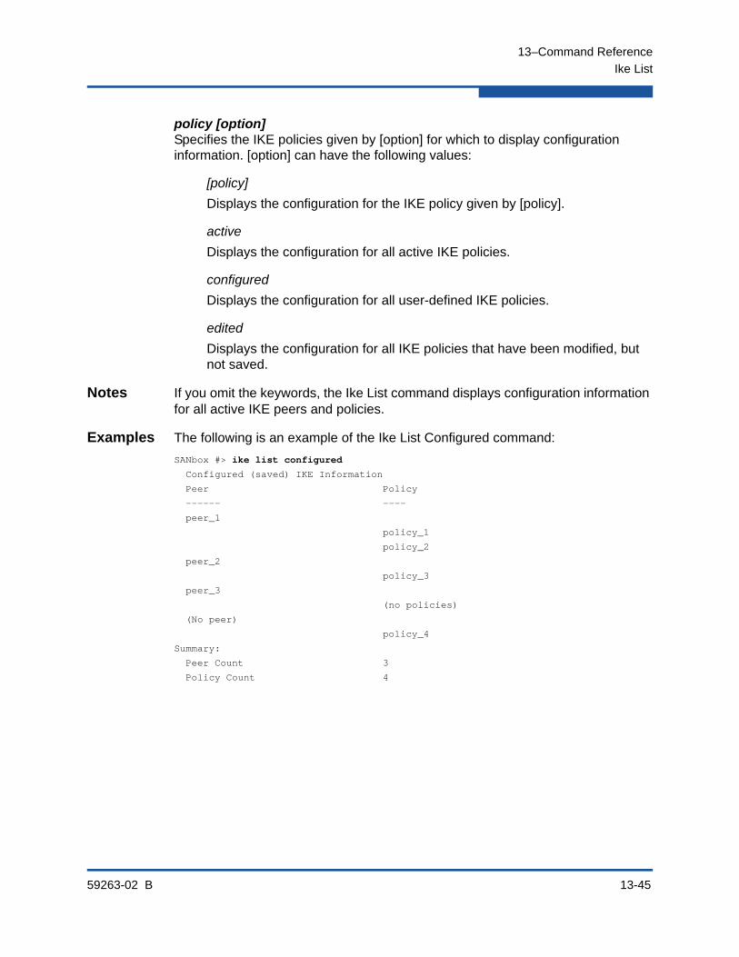
13–Command Reference
Ike List
59263-02 B 13-45
policy [option]Specifies the IKE policies given by [option] for which to display configuration information. [option] can have the following values:
[policy]
Displays the configuration for the IKE policy given by [policy].
active
Displays the configuration for all active IKE policies.
configured
Displays the configuration for all user-defined IKE policies.
edited
Displays the configuration for all IKE policies that have been modified, but not saved.
Notes If you omit the keywords, the Ike List command displays configuration information for all active IKE peers and policies.
Examples The following is an example of the Ike List Configured command:
SANbox #> ike list configured
Configured (saved) IKE Information
Peer Policy
------ ----
peer_1
policy_1
policy_2
peer_2
policy_3
peer_3
(no policies)
(No peer)
policy_4
Summary:
Peer Count 3
Policy Count 4

13–Command Reference
Ike List
13-46 59263-02 B
The following is an example of the Ike List Policy command:
SANbox (admin-ipsec) #> ike list policy policy_2
Edited (unsaved) IKE Information
policy_2
Description 65
Mode transport
LocalAddress 10.0.0.3
LocalPort 1234
RemotePort 0 (All)
Peer peer_1
Protocol udp
Action ipsec
ProtectionDesired <undefined>
LifetimeChild 3600 (seconds)
RekeyChild True
Encryption 3des_cbc
Integrity md5_96 sha1_96 sha2_256
DHGroup 1 5
Restrict True
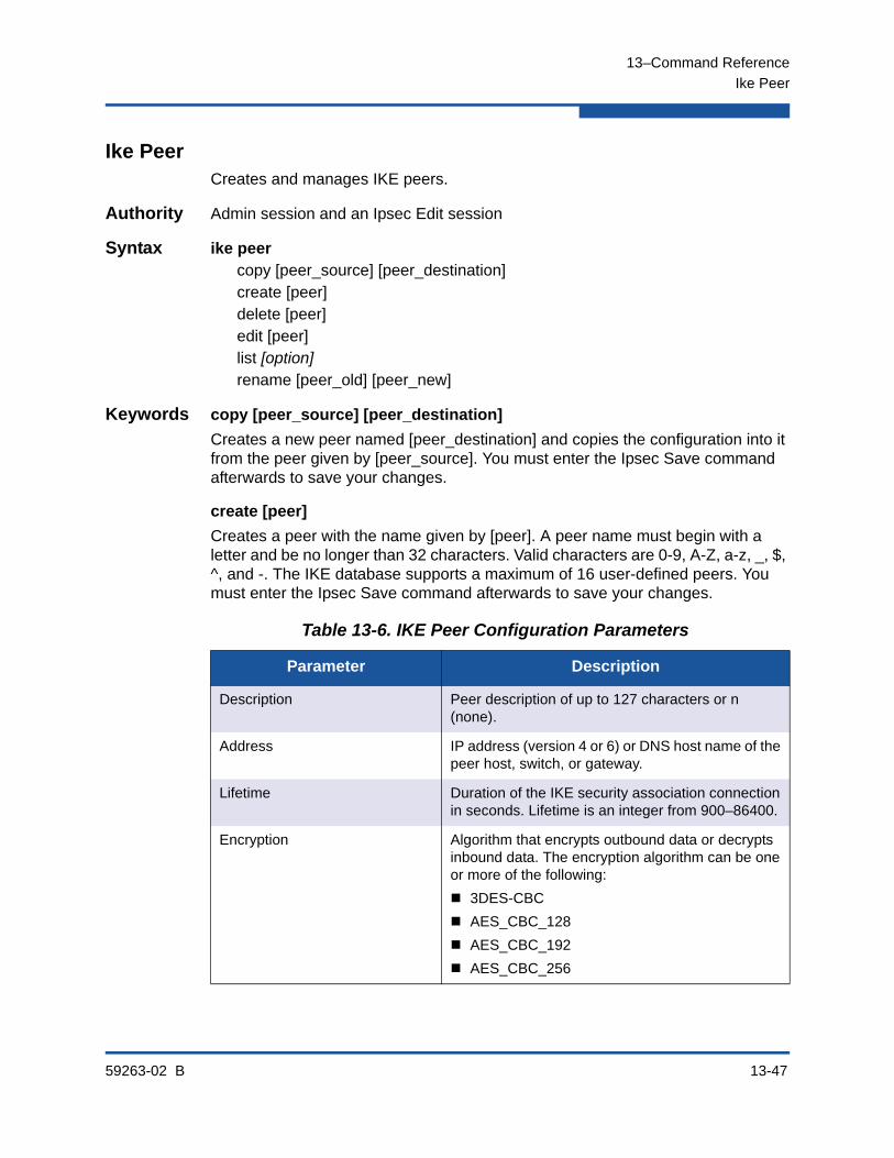
13–Command Reference
Ike Peer
59263-02 B 13-47
Ike PeerCreates and manages IKE peers.
Authority Admin session and an Ipsec Edit session
Syntax ike peercopy [peer_source] [peer_destination]create [peer]delete [peer]edit [peer]list [option]rename [peer_old] [peer_new]
Keywords copy [peer_source] [peer_destination]
Creates a new peer named [peer_destination] and copies the configuration into it from the peer given by [peer_source]. You must enter the Ipsec Save command afterwards to save your changes.
create [peer]
Creates a peer with the name given by [peer]. A peer name must begin with a letter and be no longer than 32 characters. Valid characters are 0-9, A-Z, a-z, _, $, ^, and -. The IKE database supports a maximum of 16 user-defined peers. You must enter the Ipsec Save command afterwards to save your changes.
Table 13-6. IKE Peer Configuration Parameters
Parameter Description
Description Peer description of up to 127 characters or n (none).
Address IP address (version 4 or 6) or DNS host name of the peer host, switch, or gateway.
Lifetime Duration of the IKE security association connection in seconds. Lifetime is an integer from 900–86400.
Encryption Algorithm that encrypts outbound data or decrypts inbound data. The encryption algorithm can be one or more of the following:
3DES-CBC
AES_CBC_128
AES_CBC_192
AES_CBC_256

13–Command Reference
Ike Peer
13-48 59263-02 B
Integrity Integrity (authentication) algorithm. Integrity can be one or more of the following:
MD5_96
SHA1_96
SHA2_256
AES_XCBC_96
DHGroup Diffie-Hellman group number. You can specify one or more group numbers: 1, 2, 5, 14, or 24
Restrict Algorithm and DH group restriction. The IKE responder accepts only algorithms and DH groups specified by the IKE initiator (True), or accepts all algorithms and DH groups (False).
Authentication IKE authentication method. Authentication can have the following values:
Secret—Authenticate by pre-shared keys (PSK). See the Key parameter.
Pubkey—Authenticate by public key encryption (RSA) through digital certificates. See the Certifi-cateName, SwitchIdentity, and PeerIdentity parameters.
Key(Authentication=Secret)
Pre-shared key that matches the key on the IKE peer. Key can be one of the following:
String in quotes up to 128 characters
Raw hex bytes up to 256 bytes. The number of bytes must be even.
CertificateName(Authentication=Pubkey)
Name of the local switch certificate to use to authenticate the peer device. CertificateName is a string of up to 32 characters. For more information about certificates, see the Certificate command.
SwitchIdentity(Authentication=Pubkey)
Identifier by which the switch is authenticated.SwitchIdentity can have the following values:
Unspecified—Identifier is set to the distinguished name (DN) of the local certificate’s subject.
IPv4 or IPv6 address, DNS name, or e-mail address—this value must be included in a subjectAltName extension in the local certificate.
Table 13-6. IKE Peer Configuration Parameters (Continued)
Parameter Description
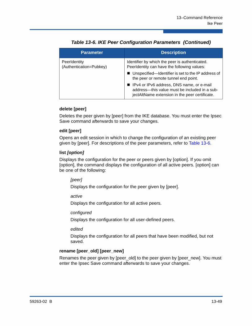
13–Command Reference
Ike Peer
59263-02 B 13-49
delete [peer]
Deletes the peer given by [peer] from the IKE database. You must enter the Ipsec Save command afterwards to save your changes.
edit [peer]
Opens an edit session in which to change the configuration of an existing peer given by [peer]. For descriptions of the peer parameters, refer to Table 13-6.
list [option]
Displays the configuration for the peer or peers given by [option]. If you omit [option], the command displays the configuration of all active peers. [option] can be one of the following:
[peer]
Displays the configuration for the peer given by [peer].
active
Displays the configuration for all active peers.
configured
Displays the configuration for all user-defined peers.
edited
Displays the configuration for all peers that have been modified, but not saved.
rename [peer_old] [peer_new]
Renames the peer given by [peer_old] to the peer given by [peer_new]. You must enter the Ipsec Save command afterwards to save your changes.
PeerIdentity(Authentication=Pubkey)
Identifier by which the peer is authenticated. PeerIdentity can have the following values:
Unspecified—Identifier is set to the IP address of the peer or remote tunnel end point.
IPv4 or IPv6 address, DNS name, or e-mail address—this value must be included in a sub-jectAltName extension in the peer certificate.
Table 13-6. IKE Peer Configuration Parameters (Continued)
Parameter Description

13–Command Reference
Ike Peer
13-50 59263-02 B
Examples The following is an example of the Ike Peer Create command:
SANbox ># admin start
SANbox (admin) #> ipsec edit
SANbox (admin-ipsec) #> ike peer create peer_1
A list of attributes with formatting will follow.
Enter a value or simply press the ENTER key to skip specifying a value.
If you wish to terminate this process before reaching the end of the list
press 'q' or 'Q' and the ENTER key to do so.
Required attributes are preceded by an asterisk.
Value (press ENTER to not specify value, 'q' to quit):
Description (string, max=127 chars, N=None) : Peer_1
*Address (hostname, IPv4, or IPv6 Address) : 10.0.0.3
Lifetime (decimal value, 900-86400 seconds) : 3600
*Encryption (select one or more encryption algorithms)
1=3des_cbc
2=aes_cbc_128
3=aes_cbc_192
4=aes_cbc_256 : 1 4
*Integrity (select one or more integrity algorithms)
1=md5_96
2=sha1_96
3=sha2_256
4=aes_xcbc_96 : 1 2 3
*DHGroup (select one or more Diffie-Hellman Groups)
1, 2, 5, 14, 24 : 2 14
Restrict (True / False) : True
*Authentication (1=secret, 2=public_key) : 1
*Key (quoted string or raw hex bytes)
maximum length for quoted string = 128
maximum length for raw hex bytes = 256
the raw hex length must be even : 0x11223344
The IKE peer has been created.
This configuration must be saved with the 'ipsec save' command
before it can take effect, or to discard this configuration
use the 'ipsec cancel' command.
SANbox (admin-IPSEC) #> ipsec save

13–Command Reference
Ike Peer
59263-02 B 13-51
The following is an example of the Ike Peer Edit command:
SANbox (admin-ipsec) #> ike peer edit peer_2
A list of attributes with formatting and current values will follow.
Enter a new value or simply press the ENTER key to accept the current value.
If you wish to terminate this process before reaching the end of the list
press 'q' or 'Q' and the ENTER key to do so.
Required attributes are preceded by an asterisk.
Current Values:
Description Peer_2 description
Address 10.0.0.4
Lifetime 4800 (seconds)
Encryption aes_cbc_128 aes_cbc_192
Integrity aes_xcbc_96
DHGroup 5 24
Restrict True
Authentication secret
Key ********
New Value (press ENTER to not specify value, 'q' to quit, 'n' for none):
Description (string, max=127 chars, N=None) :
*Address (hostname, IPv4, or IPv6 Address) :
Lifetime (decimal value, 900-86400 seconds) : 1200
*Encryption (select one or more encryption algorithms)
1=3des_cbc
2=aes_cbc_128
3=aes_cbc_192
4=aes_cbc_256 : 1
*Integrity (select one or more integrity algorithms)
1=md5_96
2=sha1_96
3=sha2_256
4=aes_xcbc_96 : 1
*DHGroup (select one or more Diffie-Hellman Groups)
1, 2, 5, 14, 24 : 1
Restrict (True / False) :
*Authentication (1=secret, 2=public_key) :
*Key (quoted string or raw hex bytes)
maximum length for quoted string = 128
maximum length for raw hex bytes = 256
the raw hex length must be even :
The IKE peer has been edited.
This configuration must be saved with the 'ipsec save' command
before it can take effect, or to discard this configuration
use the 'ipsec cancel' command.

13–Command Reference
Ike Peer
13-52 59263-02 B
The following is an example of the Ike Peer List command:
SANbox (admin-ipsec) #> ike peer list peer_1
Edited (unsaved) IKE Information
peer_1
Description Peer_1 description
Address 10.0.0.3
Lifetime 3600 (seconds)
Encryption 3des_cbc aes_cbc_256
Integrity md5_96 sha1_96 sha2_256
DHGroup 2 14
Restrict True
Authentication secret
Key ********
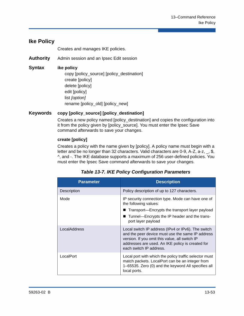
13–Command Reference
Ike Policy
59263-02 B 13-53
Ike PolicyCreates and manages IKE policies.
Authority Admin session and an Ipsec Edit session
Syntax ike policycopy [policy_source] [policy_destination]create [policy]delete [policy]edit [policy]list [option]rename [policy_old] [policy_new]
Keywords copy [policy_source] [policy_destination]
Creates a new policy named [policy_destination] and copies the configuration into it from the policy given by [policy_source]. You must enter the Ipsec Save command afterwards to save your changes.
create [policy]
Creates a policy with the name given by [policy]. A policy name must begin with a letter and be no longer than 32 characters. Valid characters are 0-9, A-Z, a-z, _, $, ^, and -. The IKE database supports a maximum of 256 user-defined policies. You must enter the Ipsec Save command afterwards to save your changes.
Table 13-7. IKE Policy Configuration Parameters
Parameter Description
Description Policy description of up to 127 characters.
Mode IP security connection type. Mode can have one of the following values:
Transport—Encrypts the transport layer payload
Tunnel—Encrypts the IP header and the trans-port layer payload
LocalAddress Local switch IP address (IPv4 or IPv6). The switch and the peer device must use the same IP address version. If you omit this value, all switch IP addresses are used. An IKE policy is created for each switch IP address.
LocalPort Local port with which the policy traffic selector must match packets. LocalPort can be an integer from 1–65535. Zero (0) and the keyword All specifies all local ports.

13–Command Reference
Ike Policy
13-54 59263-02 B
RemoteAddress(Mode=Tunnel)
IPv4 or IPv6 address of the traffic selector (with an optional address prefix length) on the remote side of the IP security tunnel
RemotePort(Mode=Tunnel)
Remote port with which the policy traffic selector must match packets. RemotePort can be an integer 1–65535. Zero (0) and the keyword All specifies all remote ports.
Peer Name of an existing peer to be associated with this policy.
Protocol(LocalPort=1–65535 orRemotePort=1–65535)
Transport protocol with which the traffic selector matches packets. Protocol can have the following values:
icmp—Internet control message protocol for IP version 4
icmp6—Internet control message protocol for IP version 6
ip4—Internet protocol version 4
tcp—Transmission control protocol
udp—User datagram protocol
any or 0—Any protocol
1–255—Numeric equivalent for standard and custom protocols
Action Action to apply for packets that match the policy. Action can be ipsec, which applies the policy’s IP security protection to the packet.
ProtectionDesired(Mode=Transport)
IP security protection protocol to apply (encapsulat-ing security payload).
LifetimeChild Duration of the IP security association connection in seconds. LifetimeChild is an integer 900–86400. The default is 3600.
RekeyChild IP security association renegotiation. Renegotiate an IP security association that is about to expire (True) or allow it to expire (False).
Table 13-7. IKE Policy Configuration Parameters (Continued)
Parameter Description

13–Command Reference
Ike Policy
59263-02 B 13-55
delete [policy]
Deletes the policy given by [policy] from the IKE database. You must enter the Ipsec Save command afterwards to save your changes.
edit [policy]
Opens an edit session in which to change the configuration of an existing IKE policy given by [policy]. For descriptions of the policy parameters, refer to Table 13-6.
Encryption One or more encryption algorithms. Encryption can be one of the following:
null
3des_cbc
aes_cbc_128
aes_cbc_192
aes_cbc_256
aes_ctr_128 (not supported on all platforms)
aes_ctr_192 (not supported on all platforms)
aes_ctr_256 (not supported on all platforms)
Integrity One or more authentication algorithms to apply to the policy:
md5_96
sha1_96
sha2_256
aes_xcbc_96
DHGroup Diffie-Hellman group number(s) to apply to the pol-icy. DHGoup can be one or more of the following: 1, 2, 5, 14, 24. If you omit this value, no Diffie-Hellman exchanges will be done for IP security association setup and rekeying.
Restrict Algorithm and DH group restriction. The IKE responder accepts only the configured algorithms and DH groups for an IKE security association (True), or accepts any algorithm and DH group (False).
Table 13-7. IKE Policy Configuration Parameters (Continued)
Parameter Description
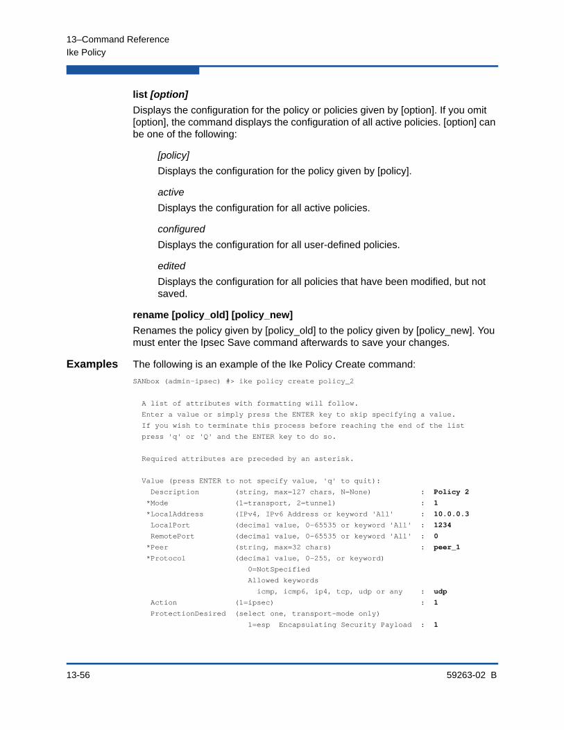
13–Command Reference
Ike Policy
13-56 59263-02 B
list [option]
Displays the configuration for the policy or policies given by [option]. If you omit [option], the command displays the configuration of all active policies. [option] can be one of the following:
[policy]
Displays the configuration for the policy given by [policy].
active
Displays the configuration for all active policies.
configured
Displays the configuration for all user-defined policies.
edited
Displays the configuration for all policies that have been modified, but not saved.
rename [policy_old] [policy_new]
Renames the policy given by [policy_old] to the policy given by [policy_new]. You must enter the Ipsec Save command afterwards to save your changes.
Examples The following is an example of the Ike Policy Create command:
SANbox (admin-ipsec) #> ike policy create policy_2
A list of attributes with formatting will follow.
Enter a value or simply press the ENTER key to skip specifying a value.
If you wish to terminate this process before reaching the end of the list
press 'q' or 'Q' and the ENTER key to do so.
Required attributes are preceded by an asterisk.
Value (press ENTER to not specify value, 'q' to quit):
Description (string, max=127 chars, N=None) : Policy 2
*Mode (1=transport, 2=tunnel) : 1
*LocalAddress (IPv4, IPv6 Address or keyword 'All' : 10.0.0.3
LocalPort (decimal value, 0-65535 or keyword 'All' : 1234
RemotePort (decimal value, 0-65535 or keyword 'All' : 0
*Peer (string, max=32 chars) : peer_1
*Protocol (decimal value, 0-255, or keyword)
0=NotSpecified
Allowed keywords
icmp, icmp6, ip4, tcp, udp or any : udp
Action (1=ipsec) : 1
ProtectionDesired (select one, transport-mode only)
1=esp Encapsulating Security Payload : 1
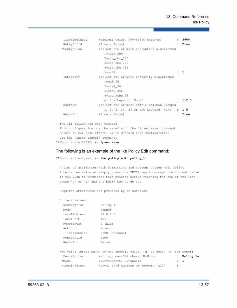
13–Command Reference
Ike Policy
59263-02 B 13-57
LifetimeChild (decimal value, 900-86400 seconds) : 3600
RekeyChild (True / False) : True
*Encryption (select one or more encryption algorithms)
1=3des_cbc
2=aes_cbc_128
3=aes_cbc_192
4=aes_cbc_256
5=null : 1
Integrity (select one or more integrity algorithms)
1=md5_96
2=sha1_96
3=sha2_256
4=aes_xcbc_96
or the keyword 'None' : 1 2 3
DHGroup (select one or more Diffie-Hellman Groups)
1, 2, 5, 14, 24 or the keyword 'None' : 1 5
Restrict (True / False) : True
The IKE policy has been created.
This configuration must be saved with the 'ipsec save' command
before it can take effect, or to discard this configuration
use the 'ipsec cancel' command.
SANbox (admin-IPSEC) #> ipsec save
The following is an example of the Ike Policy Edit command:
SANbox (admin-ipsec) #> ike policy edit policy_1
A list of attributes with formatting and current values will follow.
Enter a new value or simply press the ENTER key to accept the current value.
If you wish to terminate this process before reaching the end of the list
press 'q' or 'Q' and the ENTER key to do so.
Required attributes are preceded by an asterisk.
Current Values:
Description Policy 1
Mode tunnel
LocalAddress 10.0.0.6
LocalPort 456
RemotePort 0 (All)
Action ipsec
LifetimeChild 3600 (seconds)
RekeyChild True
Restrict False
New Value (press ENTER to not specify value, 'q' to quit, 'n' for none):
Description (string, max=127 chars, N=None) : Policy 1a
*Mode (1=transport, 2=tunnel) : 1
*LocalAddress (IPv4, IPv6 Address or keyword 'All' :
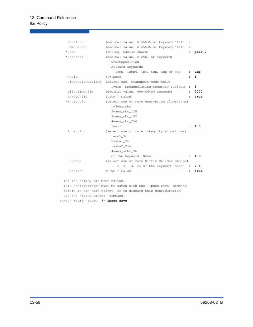
13–Command Reference
Ike Policy
13-58 59263-02 B
LocalPort (decimal value, 0-65535 or keyword 'All' :
RemotePort (decimal value, 0-65535 or keyword 'All' :
*Peer (string, max=32 chars) : peer_2
*Protocol (decimal value, 0-255, or keyword)
0=NotSpecified
Allowed keywords
icmp, icmp6, ip4, tcp, udp or any : udp
Action (1=ipsec) : 1
ProtectionDesired (select one, transport-mode only)
1=esp Encapsulating Security Payload : 1
LifetimeChild (decimal value, 900-86400 seconds) : 2000
RekeyChild (True / False) : true
*Encryption (select one or more encryption algorithms)
1=3des_cbc
2=aes_cbc_128
3=aes_cbc_192
4=aes_cbc_256
5=null : 1 3
Integrity (select one or more integrity algorithms)
1=md5_96
2=sha1_96
3=sha2_256
4=aes_xcbc_96
or the keyword 'None' : 1 3
DHGroup (select one or more Diffie-Hellman Groups)
1, 2, 5, 14, 24 or the keyword 'None' : 2 5
Restrict (True / False) : true
The IKE policy has been edited.
This configuration must be saved with the 'ipsec save' command
before it can take effect, or to discard this configuration
use the 'ipsec cancel' command.
SANbox (admin-IPSEC) #> ipsec save

13–Command Reference
Ike Policy
59263-02 B 13-59
The following is an example of the Ike Policy List command:
SANbox (admin-ipsec) #> ike policy list policy_2
Edited (unsaved) IKE Information
policy_2
Description Policy 2
Mode transport
LocalAddress 10.0.0.3
LocalPort 1234
RemotePort 0 (All)
Peer peer_1
Protocol udp
Action ipsec
ProtectionDesired <undefined>
LifetimeChild 3600 (seconds)
RekeyChild True
Encryption 3des_cbc
Integrity md5_96 sha1_96 sha2_256
DHGroup 1 5
Restrict True

13–Command Reference
Image
13-60 59263-02 B
ImageManages and installs switch firmware.
Authority Admin session
Syntax imagecleanupfetch [account_name] [ip_address] [file_source] [file_destination]installlisttftp [ip_address] [file_source] [file_destination]unpack [file]
Keywords cleanup
Removes all firmware image files from the switch. All firmware image files are removed automatically each time the switch is reset.
fetch [account_name] [ip_address] [file_source] [file_destination]
Retrieves image file given by [file_source] using FTP and stores it on the switch with the file name given by [file_destination]. The image file is retrieved from the host IP address given by [ip_address]. [ip_address] can be an IP address (version 4 or 6) or a DNS host name. If an account name needs a password to access the FTP server, the system will prompt you for it.
install
Downloads firmware from a remote host to the switch, installs the firmware, then resets the switch to activate the firmware. This is disruptive. The command prompts you for the following:
File transfer protocol (FTP or TFTP)
IP address or DNS host name of the remote host
An account name and password on the remote host (FTP only)
Pathname for the firmware image file
list
Displays the list of image files that reside on the switch.
tftp [ip_address] [file_source] [file_destination]
Retrieves image file given by [file_source] using TFTP and stores it on the switch with the file name given by [file_destination]. The image file is retrieved from the host IP address given by [ip_address]. [ip_address] can be an IP address (version 4 or 6) or a DNS host name.

13–Command Reference
Image
59263-02 B 13-61
unpack [file]
Installs the firmware file given by [file]. After unpacking the file, a message appears confirming successful unpacking. The switch must be reset for the new firmware to take effect.
Notes To provide consistent performance throughout the fabric, ensure that all switches are running the same version of firmware.
To install firmware when the management workstation has an FTP server, use the Image Install command or the Firmware Install command.
Examples The following is an example of the Image Install command:
SANbox #> admin start
SANbox (admin) #> image install
The switch will be reset. This process will cause a disruption to I/O traffic.
Continuing with this action will terminate all management sessions, including any Telnet sessions. When the firmware activation is complete,
you may log in to the switch again.
Do you want to continue? [y/n]: y
Press 'q' and the ENTER key to abort this command.
FTP or TFTP : ftp
User Account : johndoe
IP Address : 10.0.0.254
Source Filename : 8.0.00.xx_epc
About to install image. Do you want to continue? [y/n] y
Connected to 10.0.0.254 (10.0.0.254).
220 localhost.localdomain FTP server (Version wu-2.6.1-18) ready.
331 Password required for johndoe.
Password: xxxxxxxxx
230 User johndoe logged in.
bin
200 Type set to I.
verbose
Verbose mode off.
This may take several seconds...
The switch will now reset.
Connection closed by foreign host.
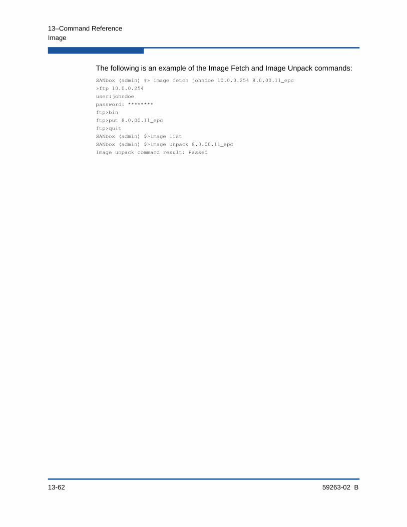
13–Command Reference
Image
13-62 59263-02 B
The following is an example of the Image Fetch and Image Unpack commands:
SANbox (admin) #> image fetch johndoe 10.0.0.254 8.0.00.11_epc
>ftp 10.0.0.254
user:johndoe
password: ********
ftp>bin
ftp>put 8.0.00.11_epc
ftp>quit
SANbox (admin) $>image list
SANbox (admin) $>image unpack 8.0.00.11_epc
Image unpack command result: Passed
13–Command Reference
Ipsec
59263-02 B 13-63
IpsecManages the IP Security database. The IP Security database consists of the Security Association database and the Security Policy database. The Ipsec Edit command opens a session in which to create and manage associations and policies.
Authority Admin session except for the History keyword. The Clear keyword also requires an Ipsec Edit session.
Syntax ipseccancelclearedithistorylimitssave
Keywords cancel
Closes the current Ipsec Edit session. Any unsaved changes are lost.
clear
Deletes all IP security associations, IP security policies, IKE peers, and IKE policies from the volatile edit copies of the IP security and IKE databases. This keyword requires an Ipsec Edit session. This keyword does not affect the non-volatile IP security configuration. However, if you enter the Ipsec Clear command followed by the Ipsec Save command, the non-volatile IP security configuration will be deleted from the switch.
edit
Open an Ipsec Edit session in which to create and manage IP security associations and policies, and IKE peers and policies. This keyword requires an Admin session. Ipsec Edit session commands include the Ike Peer, Ike Policy, Ipsec Clear, Ipsec Association, and Ipsec Policy commands.
NOTE:
The preferred method for deleting the IP security configuration from the switch is the Reset Ipsec command.

13–Command Reference
Ipsec
13-64 59263-02 B
history
Displays a history of IP security modifications. This keyword does not require an Admin session. History information includes the following:
Time of the most recent IP security database modification and the user who performed it
Checksums for the active and inactive IP security databases and the IKE database
limits
Displays the maximum and current numbers of configured IP security associations, IP security policies, IKE peers, and IKE policies. This keyword does not require an Admin session nor an Ipsec Edit session. However, in an Ipsec Edit session, this command displays the number of both configured associations, peers, and policies, plus those created in the edit session but not yet saved.
save
Saves changes made during the current Ipsec Edit session.
Examples The following is an example of the Ipsec History command:
SANbox #> ipsec history
IPsec Database History
----------------------
ConfigurationLastEditedBy johndoe@OB-session5
ConfigurationLastEditedOn Sat Mar 8 07:14:36 2008
Active Database Checksum 00000144
Inactive Database Checksum 00000385
IKE Database Checksum 00000023
The following is an example of the Ipsec Limits command:
SANbox #> ipsec limits
Configured (saved) IPsec Information
IPsec Attribute Maximum Current
--------------- ------- -------
MaxConfiguredSAs 512 0
MaxConfiguredSPs 128 0
MaxConfiguredIKEPeers 16 0
MaxConfiguredIKEPolicies 256 0
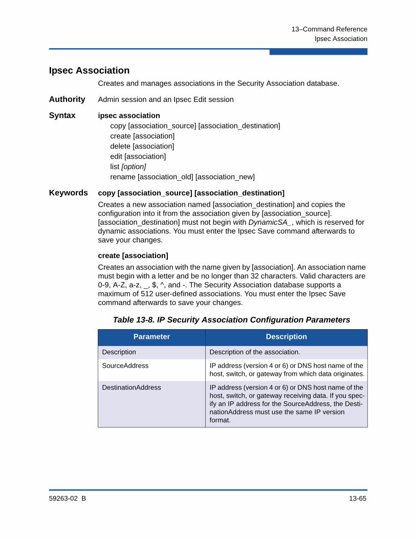
13–Command Reference
Ipsec Association
59263-02 B 13-65
Ipsec AssociationCreates and manages associations in the Security Association database.
Authority Admin session and an Ipsec Edit session
Syntax ipsec associationcopy [association_source] [association_destination]create [association]delete [association]edit [association]list [option]rename [association_old] [association_new]
Keywords copy [association_source] [association_destination]
Creates a new association named [association_destination] and copies the configuration into it from the association given by [association_source]. [association_destination] must not begin with DynamicSA_, which is reserved for dynamic associations. You must enter the Ipsec Save command afterwards to save your changes.
create [association]
Creates an association with the name given by [association]. An association name must begin with a letter and be no longer than 32 characters. Valid characters are 0-9, A-Z, a-z, _, $, ^, and -. The Security Association database supports a maximum of 512 user-defined associations. You must enter the Ipsec Save command afterwards to save your changes.
Table 13-8. IP Security Association Configuration Parameters
Parameter Description
Description Description of the association.
SourceAddress IP address (version 4 or 6) or DNS host name of the host, switch, or gateway from which data originates.
DestinationAddress IP address (version 4 or 6) or DNS host name of the host, switch, or gateway receiving data. If you spec-ify an IP address for the SourceAddress, the Desti-nationAddress must use the same IP version format.
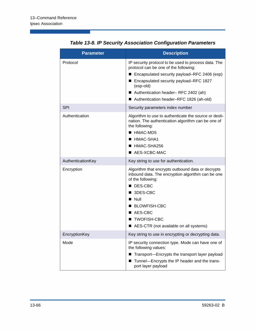
13–Command Reference
Ipsec Association
13-66 59263-02 B
Protocol IP security protocol to be used to process data. The protocol can be one of the following:
Encapsulated security payload–RFC 2406 (esp)
Encapsulated security payload–RFC 1827 (esp-old)
Authentication header– RFC 2402 (ah)
Authentication header–RFC 1826 (ah-old)
SPI Security parameters index number
Authentication Algorithm to use to authenticate the source or desti-nation. The authentication algorithm can be one of the following:
HMAC-MD5
HMAC-SHA1
HMAC-SHA256
AES-XCBC-MAC
AuthenticationKey Key string to use for authentication.
Encryption Algorithm that encrypts outbound data or decrypts inbound data. The encryption algorithm can be one of the following:
DES-CBC
3DES-CBC
Null
BLOWFISH-CBC
AES-CBC
TWOFISH-CBC
AES-CTR (not available on all systems)
EncryptionKey Key string to use in encrypting or decrypting data.
Mode IP security connection type. Mode can have one of the following values:
Transport—Encrypts the transport layer payload
Tunnel—Encrypts the IP header and the trans-port layer payload
Table 13-8. IP Security Association Configuration Parameters
Parameter Description

13–Command Reference
Ipsec Association
59263-02 B 13-67
delete [association]
Deletes the specified association given by [association] from the Security Association database. You must enter the Ipsec Save command afterwards to save your changes.
edit [association]
Opens an edit session in which to change the configuration of an existing association given by [association]. For descriptions of the association parameters, refer to Table 13-8. If the connection is not secure (SSH is disabled), the AuthenticationKey and EncryptionKey values are masked.
list [option]
Displays the configuration for the associations given by [option]. If you omit [option], the command displays the configuration of all active associations. [option] can be one of the following:
[association]
Displays the configuration for the association given by [association].
active
Displays the configuration for all active associations.
configured
Displays the configuration for all user-defined associations.
edited
Displays the configuration for all associations that have been modified, but not saved.
rename [association_old] [association_new]
Renames the association given by [association_old] to the association given by [association_new]. You must enter the Ipsec Save command afterwards to save your changes. Dynamic associations cannot be renamed.

13–Command Reference
Ipsec Association
13-68 59263-02 B
Examples The following is an example of the Ipsec Association Create command:
SANbox #> admin start
SANbox (admin) #> ipsec edit
SANbox (admin-ipsec) #> ipsec association create h2h-sh-sa
A list of attributes with formatting will follow.
Enter a value or simply press the ENTER key to skip specifying a value.
If you wish to terminate this process before reaching the end of the list
press 'q' or 'Q' and the ENTER key to do so.
Required attributes are preceded by an asterisk.
Value (press ENTER to not specify value, 'q' to quit):
Description (string value, 0-127 bytes) : Host-to-host: switch->host
*SourceAddress (hostname, IPv4, or IPv6 Address) : fe80::2c0:ddff:fe03:d4c1
*DestinationAddress (hostname, IPv4, or IPv6 Address) : fe80::250:daff:feb7:9d02
*Protocol (1=esp, 2=esp-old, 3=ah, 4=ah-old) : 1
*SPI (decimal value, 256-4294967295) : 333
Authentication (select an authentication algorithm)
1=hmac-md5 (16 byte key)
2=hmac-sha1 (20 byte key)
3=hmac-sha256 (32 byte key)
4=aes-xcbc-mac (16 byte key)
authentication algorithm choice : 2
*AuthenticationKey (quoted string or raw hex bytes) : "12345678901234567890"
*Encryption (select an encryption algorithm)
1=des-cbc (8 byte key)
2=3des-cbc (24 byte key)
3=null (0 byte key)
4=blowfish-cbc (5-56 byte key)
5=aes-cbc (16/24/32 byte key)
6=twofish-cbc (16-32 byte key)
encryption algorithm choice : 2
*EncryptionKey (quoted string or raw hex bytes) : "123456789012345678901234" Mode (1=transport, 2=tunnel) : 1
The security association has been created.
This configuration must be saved with the 'ipsec save' command
before it can take effect, or to discard this configuration
use the 'ipsec cancel' command.

13–Command Reference
Ipsec List
59263-02 B 13-69
Ipsec ListDisplays information about IP security associations and policies.
Authority None
Syntax ipsec listactiveassociation [option]configurededitedpolicy [option]
Keywords active
Displays a summary of active associations and policies. This is the default.
association [option]
Displays the configuration for the associations given by [option]. If you omit [option], the command displays the configuration of all active associations. [option] can be one of the following:
[association]
Displays the configuration for the association given by [association].
active
Displays the configuration for all active associations.
configured
Displays the configuration for all user-defined associations.
edited
Displays the configuration for all associations that have been modified, but not saved.
configured
Displays a summary of the user-defined associations and policies.
edited
Displays a summary of the associations and policies that have been modified, but not saved.
13–Command Reference
Ipsec List
13-70 59263-02 B
policy [option]
Displays the configuration for the policies given by [option]. If you omit [option], the command displays the configuration of all active policies. [option] can be one of the following:
[policy]
Displays the configuration for the policy given by [policy].
active
Displays the configuration for all active policies.
configured
Displays the configuration for all user-defined policies.
edited
Displays the configuration for all policies that have been modified, but not saved.
Examples The following is an example of the Ipsec List command:
SANbox #> ipsec list
Active IPsec Information
Security Association Database
-----------------------------
h2h-sh-sa
h2h-hs-sa
Security Policy Database
------------------------
h2h-hs-sp
h2h-sh-sp
Summary
-------
Security Association Count: 2
Security Policy Count: 2
The following is an example of the Ipsec List Association command:
SANbox #> ipsec list association
Active IPsec Information
h2h-sh-sa
Description: Host-to-host: switch->host
Source: fe80::2c0:ddff:fe03:d4c1

13–Command Reference
Ipsec List
59263-02 B 13-71
Destination: fe80::250:daff:feb7:9d02
Protocol: esp SPI: 333 (0x14d)
Authentication: hmac-sha1 ********
Encryption: 3des-cbc ********
Mode: transport
h2h-hs-sa
Description: Host-to-host: host->switch
Source: fe80::250:daff:feb7:9d02
Destination: fe80::2c0:ddff:fe03:d4c1
Protocol: esp SPI: 444 (0x1bc)
Authentication: hmac-sha1 ********
Encryption: 3des-cbc ********
Mode: transport
The following is an example of the Ipsec List Policy command:
SANbox #> ipsec list policy
Active IPsec Information
h2h-hs-sp
Description: Host-to-host: host->switch
Source: fe80::250:daff:feb7:9d02/128
Destination: fe80::2c0:ddff:fe03:d4c1/128
Protocol: any
Direction: in Priority: 0 Action: ipsec
Mode: transport
Rule Protocol Mode Level
---- -------- --------- -----
1 esp transport require
h2h-sh-sp
Description: Host-to-host: switch->host
Source: fe80::2c0:ddff:fe03:d4c1/128
Destination: fe80::250:daff:feb7:9d02/128
Protocol: any
Direction: out Priority: 0 Action: ipsec
Mode: transport
Rule Protocol Mode Level
---- -------- --------- -----
1 esp transport require

13–Command Reference
Ipsec Policy
13-72 59263-02 B
Ipsec PolicyManages policies in the Security Policy database.
Authority Admin session and an Ipsec Edit session
Syntax ipsec policycopy [policy_source] [policy_destination]create [policy]delete [policy]edit [policy]list [option]rename [policy_old] [policy_new]
Keywords copy [policy_source] [policy_destination]
Creates a new policy named [policy_destination] and copies the configuration into it from the policy given by [policy_source]. You must enter the Ipsec Save command afterwards to save your changes. [policy_destination] must not begin with DynamicSP_, which is reserved for dynamic policies.
create [policy]
Creates a policy with the name given by [policy]. A policy name must begin with a letter and be no longer than 32 characters. Valid characters are 0-9, A-Z, a-z, _, $, ^, and -. The Security Policy database supports a maximum of 128 user-defined policies. You must enter the Ipsec Save command afterwards to save your changes. Table 13-9 describes the policy parameters:
Table 13-9. IP Security Policy Configuration Parameters
Parameter Description
Description Description of the policy
SourceAddress IP address (version 4 or 6) or DNS host name of the host, switch, or gateway from which data originates.
SourcePort Source port number (1–65535)
DestinationAddress IP address (version 4 or 6) or DNS host name of the host, switch, or gateway receiving data. If you specify an IP address for SourceAddress, DestinationAddress must use the same IP version address format.
DestinationPort Destination port number (1–65535)
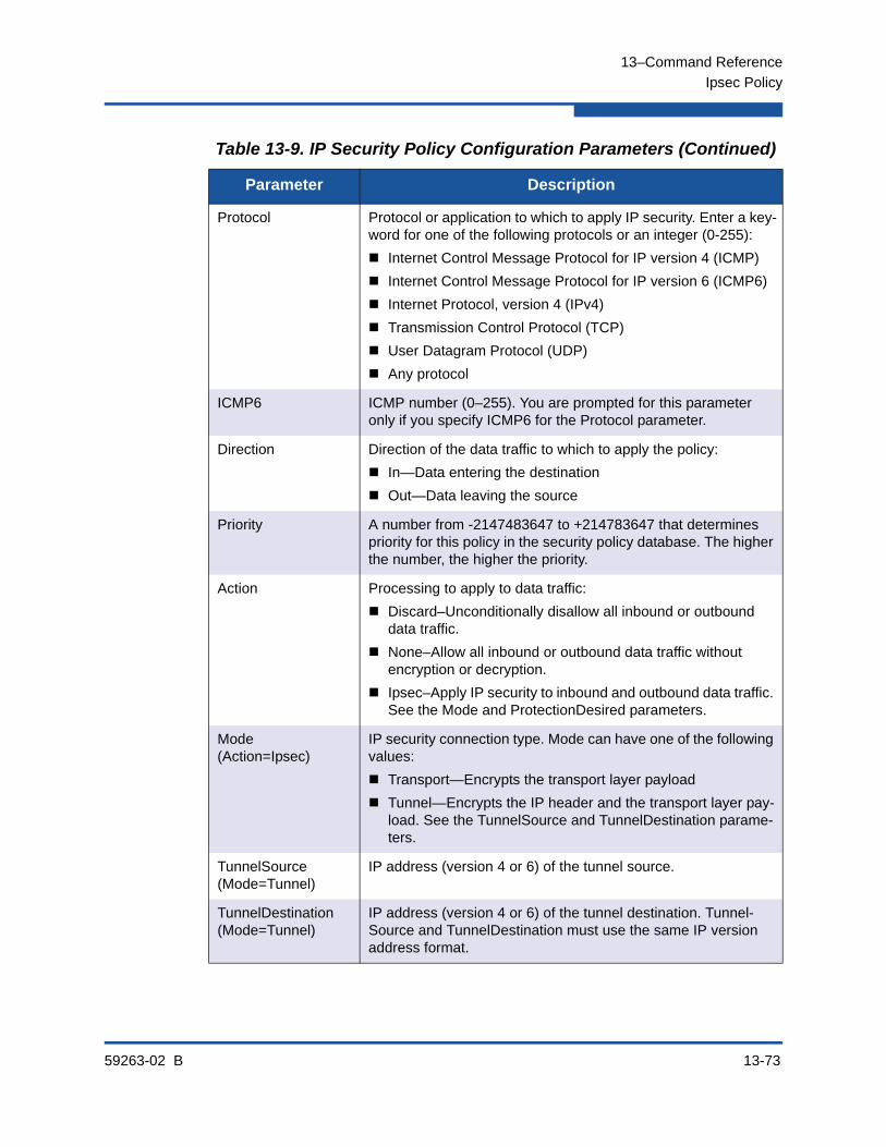
13–Command Reference
Ipsec Policy
59263-02 B 13-73
Protocol Protocol or application to which to apply IP security. Enter a key-word for one of the following protocols or an integer (0-255):
Internet Control Message Protocol for IP version 4 (ICMP)
Internet Control Message Protocol for IP version 6 (ICMP6)
Internet Protocol, version 4 (IPv4)
Transmission Control Protocol (TCP)
User Datagram Protocol (UDP)
Any protocol
ICMP6 ICMP number (0–255). You are prompted for this parameter only if you specify ICMP6 for the Protocol parameter.
Direction Direction of the data traffic to which to apply the policy:
In—Data entering the destination
Out—Data leaving the source
Priority A number from -2147483647 to +214783647 that determines priority for this policy in the security policy database. The higher the number, the higher the priority.
Action Processing to apply to data traffic:
Discard–Unconditionally disallow all inbound or outbound data traffic.
None–Allow all inbound or outbound data traffic without encryption or decryption.
Ipsec–Apply IP security to inbound and outbound data traffic. See the Mode and ProtectionDesired parameters.
Mode(Action=Ipsec)
IP security connection type. Mode can have one of the following values:
Transport—Encrypts the transport layer payload
Tunnel—Encrypts the IP header and the transport layer pay-load. See the TunnelSource and TunnelDestination parame-ters.
TunnelSource(Mode=Tunnel)
IP address (version 4 or 6) of the tunnel source.
TunnelDestination(Mode=Tunnel)
IP address (version 4 or 6) of the tunnel destination. Tunnel-Source and TunnelDestination must use the same IP version address format.
Table 13-9. IP Security Policy Configuration Parameters (Continued)
Parameter Description

13–Command Reference
Ipsec Policy
13-74 59263-02 B
delete [policy]
Deletes the policy given by [policy] from the Security Policy database. You must enter the Ipsec Save command afterwards to save your changes.
edit [policy]
Opens an edit session in which to change the configuration of an existing policy given by [policy]. For descriptions of the policy parameters, refer to Table 13-9.
ProtectionDesired(Action=Ipsec)
Type of IP security protection to apply.
AH—Authentication header. Protects against modifications to the data. See the ahRuleLevel parameter.
ESP–Encapsulating security payload. Protects against view-ing the data. See the espRuleLevel parameter.
Both–Apply both AH and ESP protection. See the ahRule-Level and espRuleLevel parameters.
ahRuleLevel(ProtectionDesired=ahRuleLevel or Both)
Rule level to apply for AH protection. You are prompted for this parameter only if you specify AH or Both for the ProtectionDe-sired parameter.
Default—use the system wide default for the protocol
Use—use a security association if one is available
Require—a security association is required whenever a packet is sent that is matched with the policy
espRuleLevel(ProtectionDesired=ESP or Both)
Rule level to apply for ESP protection.
Default—use the system wide default for the protocol
Use—use a security association if one is available
Require—a security association is required whenever a packet is sent that is matched with the policy
Table 13-9. IP Security Policy Configuration Parameters (Continued)
Parameter Description

13–Command Reference
Ipsec Policy
59263-02 B 13-75
list [option]
Displays the configuration for the policies given by [option]. If you omit [option], the command displays the configuration of all active policies. [option] can be one of the following:
[policy]
Displays the configuration for the policy given by [policy].
active
Displays the configuration for all active policies.
configured
Displays the configuration for all user-defined policies.
edited
Displays the configuration for all policies that have been modified, but not saved.
rename [policy_old] [policy_new]
Renames the policy given by [policy_old] to the policy given by [policy_new]. You must enter the Ipsec Save command afterwards to save your changes. Dynamic policies cannot be renamed.

13–Command Reference
Ipsec Policy
13-76 59263-02 B
Examples The following is an example of the Ipsec Policy Create command:
SANbox #> admin start
SANbox (admin) #> ipsec edit
SANbox (admin-ipsec) #> ipsec policy create h2h-sh-sp
A list of attributes with formatting will follow.
Enter a value or simply press the ENTER key to skip specifying a value.
If you wish to terminate this process before reaching the end of the list
press 'q' or 'Q' and the ENTER key to do so.
Required attributes are preceded by an asterisk.
Value (press ENTER to not specify value, 'q' to quit):
Description (string value, 0-127 bytes) : Host-to-host: switch->host
*SourceAddress (hostname, IPv4, or IPv6 Address/[PrefixLength]): fe80::2c0:ddff:fe03:d4c1
SourcePort (decimal value, 1-65535) :
*DestinationAddress (hostname, IPv4, or IPv6 Address/[PrefixLength]): fe80::250:daff:feb7:9d02
DestinationPort (decimal value, 1-65535) :
*Protocol (decimal value, or keyword)
Allowed keywords
icmp, icmp6, ip4, tcp, udp or any : any
*Direction (1=in, 2=out) : 2
Priority (value, -2147483647 to +214783647) :
*Action (1=discard, 2=none, 3=ipsec) : 3
Mode (1=transport, 2=tunnel) : 2
*TunnelSource (IPv4, or IPv6 Address) : fe91::3d1:eedd:bf14:e5d2
*TunnelDestination (IPv4, or IPv6 Address) : fe91::361:ebdd:bfc8:0e13
*ProtectionDesired (select one, transport-mode only)
1=ah Authentication Header
2=esp Encapsulating Security Payload
3=both : 2
*espRuleLevel (1=default, 2=use, 3=require) : 3
The security policy has been created.
This configuration must be saved with the 'ipsec save' command
before it can take effect, or to discard this configuration
use the 'ipsec cancel' command.

13–Command Reference
Key
59263-02 B 13-77
KeyCreates and manages public/private key pairs in the PKI database.
Authority Admin. The List keyword does not require an Admin session.
Syntax keydelete [key_name]generate [key_name] size [size] forceimport [key_name] [file_name] forcelist [key_name]
Keywords delete [key_name]
Deletes a public/private key pair from the PKI database.
generate [key_name] size [size] force
Creates a public/private key pair with the name given by [key_name] of the size in bits given by [size]. The optional keyword Force overwrites an existing key pair with the same name. [size] can be one of the following:
512
Creates a public/private key pair of 512 bits
1024
Creates a public/private key of 1,024 bits
2048
Creates a public/private key of 2,048 bits
import [key_name] [file_name] force
Imports the public/private key pair file given by [file_name] into the PKI database with the name given by [key_name]. The optional keyword Force overwrites an existing key pair with the same name.
list [key_name]
Displays detailed information about the public/private key pair given by [key_name]. If you omit [key_name], the command lists all key pairs in the PKI database.
Notes For information about creating a certificate request, see the Certificate Generate Request command.

13–Command Reference
Key
13-78 59263-02 B
Examples The following is an example of the Key Generate command:
SANbox #> admin start
SANbox (admin) #>: key generate key512 size 512
The following is an example of the Key List command for key512:
SANbox #> key list key512
Key key512:
private key with:
pubkey: RSA 512 bits
keyid: 49:80:4c:aa:d3:c3:bc:c7:f5:b1:41:34:ce:71:48:1d:b9:b3:d9:f9
subjkey: f4:b6:b9:27:25:7a:5a:69:a0:9e:cf:14:cd:3c:88:e9:d5:b1:aa:4a
The following is an example of the Key List command:
SANbox #> key list
Installed Keys:
key512
key2048
key1024
* indicates key has a matching local certificate
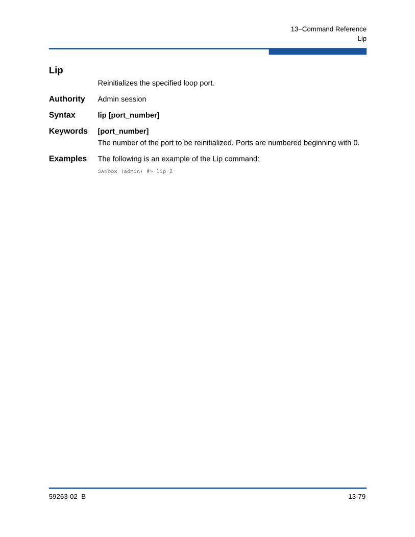
13–Command Reference
Lip
59263-02 B 13-79
LipReinitializes the specified loop port.
Authority Admin session
Syntax lip [port_number]
Keywords [port_number]
The number of the port to be reinitialized. Ports are numbered beginning with 0.
Examples The following is an example of the Lip command:
SANbox (admin) #> lip 2

13–Command Reference
Logout
13-80 59263-02 B
LogoutCloses the Telnet session.
Authority None
Syntax logout
Notes You can also press Control-D to close the Telnet session.

13–Command Reference
Passwd
59263-02 B 13-81
PasswdChanges a user account’s password.
Authority Admin account name and an Admin session to change another account’s password; you can change you own password without an Admin session.
Syntax passwd [account_name]
Keywords [account_name]
The user account name. To change the password for an account name other than your own, you must open an Admin session with the account name Admin. If you omit [account_name], you will be prompted to change the password for the current account name.
Examples The following is an example of the Passwd command:
SANbox #> admin start
SANbox (admin) #> passwd user2
Press 'q' and the ENTER key to abort this command.
account OLD password : ********
account NEW password (8-20 chars) : ********
please confirm account NEW password: ********
password has been changed.

13–Command Reference
Ping
13-82 59263-02 B
PingInitiates an attempt to communicate with another switch over an Ethernet network and reports the result.
Authority None
Syntax ping[host_name]-ipv4 [host_address]-ipv6 [host_address]
Keywords [host_name]
DNS host name of the switch you want to query. [host_name] is a character string of 2–125 characters made up of one or more subdomains delimited by periods (.). The following naming rules apply:
Valid characters are alphanumeric characters, period (.), and hyphen (-).
Each subdomain must be a minimum of two alphanumeric characters.
Each subdomain must start and end with an alphanumeric character.
A host name can end with a period (.).
-ipv4 [host_address]
IP address (version 4) or DNS host name of the switch you want to query. Broadcast IP addresses, such as 255.255.255.255, are not valid.
-ipv6 [host_address]
IP address (version 6) or DNS host name of the switch you want to query.
Examples The following is an example of a successful Ping command:
SANbox #> ping 10.20.11.57
Ping command issued. Waiting for response...
SANbox #>
Response successfully received from 10.20.11.57.
This following is an example of an unsuccessful Ping command:
SANbox #> ping 10.20.11.57
Ping command issued. Waiting for response...
No response from 10.20.11.57. Unreachable.
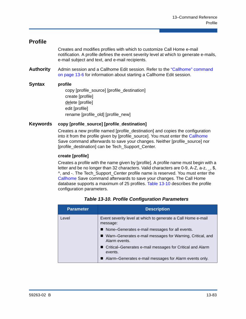
13–Command Reference
Profile
59263-02 B 13-83
ProfileCreates and modifies profiles with which to customize Call Home e-mail notification. A profile defines the event severity level at which to generate e-mails, e-mail subject and text, and e-mail recipients.
Authority Admin session and a Callhome Edit session. Refer to the “Callhome” command on page 13-6 for information about starting a Callhome Edit session.
Syntax profilecopy [profile_source] [profile_destination]create [profile]delete [profile]edit [profile]rename [profile_old] [profile_new]
Keywords copy [profile_source] [profile_destination]
Creates a new profile named [profile_destination] and copies the configuration into it from the profile given by [profile_source]. You must enter the Callhome Save command afterwards to save your changes. Neither [profile_source] nor [profile_destination] can be Tech_Support_Center.
create [profile]
Creates a profile with the name given by [profile]. A profile name must begin with a letter and be no longer than 32 characters. Valid characters are 0-9, A-Z, a-z, _, $, ^, and -. The Tech_Support_Center profile name is reserved. You must enter the Callhome Save command afterwards to save your changes. The Call Home database supports a maximum of 25 profiles. Table 13-10 describes the profile configuration parameters.
Table 13-10. Profile Configuration Parameters
Parameter Description
Level Event severity level at which to generate a Call Home e-mail message:
None–Generates e-mail messages for all events.
Warn–Generates e-mail messages for Warning, Critical, and Alarm events.
Critical–Generates e-mail messages for Critical and Alarm events.
Alarm–Generates e-mail messages for Alarm events only.

13–Command Reference
Profile
13-84 59263-02 B
delete [profile]
Deletes the specified profile given by [profile] from the Call Home database. You must enter the Callhome Save command afterwards to save your changes.
edit [profile]
Opens an edit session in which to change the configuration of an existing profile given by [profile]. The Tech_Support_Center profile can be edited. For descriptions of the profile parameters, refer to Table 13-10. The CaptureEnabled parameter is displayed only when modifying the Tech_Support_Center profile.
rename [profile_old] [profile_new]
Renames the profile given by [profile_old] to the profile given by [profile_new]. You must enter the Callhome Save command afterwards to save your changes.
Format Level of detail to be included in the e-mail message:
ShortText–includes switch and event information.
FullText–includes switch information, event information, Call Home contact information, and SNMP contact information.
Tsc1–includes switch and event information in a format intended for automated e-mail readers.
MaxSize Maximum number of characters allowed in the e-mail message. Decreasing this parameter makes for easier reading on small dis-play devices such as cell phones. The minimum is 650. The max-imum and default is 100,000.
EmailSubject E-mail subject of up to 64 characters
RecipientMail Recipient e-mail addresses; maximum of 10 addresses. The for-mat is account@domain.
CaptureEnabled Enables (True) or disables (False) the data capture configuration only when creating the Tech_Support_Center profile. For more information about the data capture configuration, refer to the Capture command.
Table 13-10. Profile Configuration Parameters (Continued)
Parameter Description
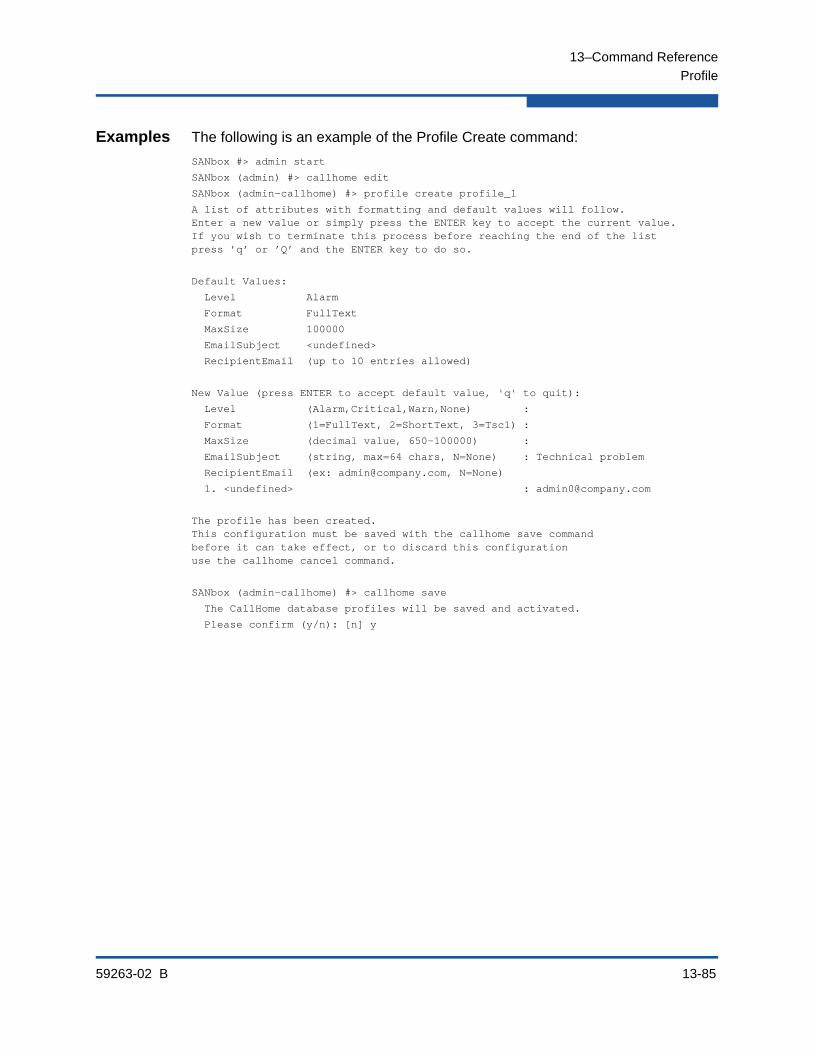
13–Command Reference
Profile
59263-02 B 13-85
Examples The following is an example of the Profile Create command:
SANbox #> admin start
SANbox (admin) #> callhome edit
SANbox (admin-callhome) #> profile create profile_1
A list of attributes with formatting and default values will follow.Enter a new value or simply press the ENTER key to accept the current value.If you wish to terminate this process before reaching the end of the listpress ’q’ or ’Q’ and the ENTER key to do so.
Default Values:
Level Alarm
Format FullText
MaxSize 100000
EmailSubject <undefined>
RecipientEmail (up to 10 entries allowed)
New Value (press ENTER to accept default value, 'q' to quit):
Level (Alarm,Critical,Warn,None) :
Format (1=FullText, 2=ShortText, 3=Tsc1) :
MaxSize (decimal value, 650-100000) :
EmailSubject (string, max=64 chars, N=None) : Technical problem
RecipientEmail (ex: [email protected], N=None)
1. <undefined> : [email protected]
The profile has been created.This configuration must be saved with the callhome save commandbefore it can take effect, or to discard this configurationuse the callhome cancel command.
SANbox (admin-callhome) #> callhome save
The CallHome database profiles will be saved and activated.
Please confirm (y/n): [n] y
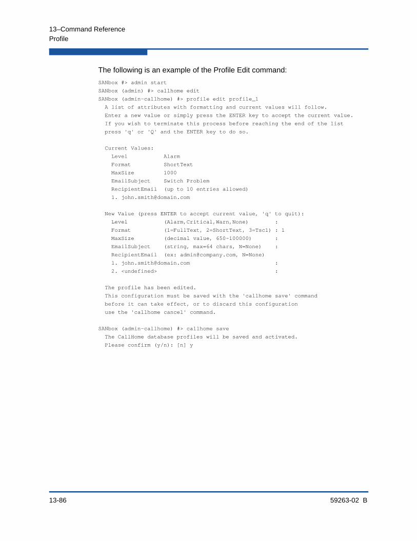
13–Command Reference
Profile
13-86 59263-02 B
The following is an example of the Profile Edit command:
SANbox #> admin start
SANbox (admin) #> callhome edit
SANbox (admin-callhome) #> profile edit profile_1
A list of attributes with formatting and current values will follow.
Enter a new value or simply press the ENTER key to accept the current value.
If you wish to terminate this process before reaching the end of the list
press 'q' or 'Q' and the ENTER key to do so.
Current Values:
Level Alarm
Format ShortText
MaxSize 1000
EmailSubject Switch Problem
RecipientEmail (up to 10 entries allowed)
New Value (press ENTER to accept current value, 'q' to quit):
Level (Alarm,Critical,Warn,None) :
Format (1=FullText, 2=ShortText, 3=Tsc1) : 1
MaxSize (decimal value, 650-100000) :
EmailSubject (string, max=64 chars, N=None) :
RecipientEmail (ex: [email protected], N=None)
1. [email protected] :
2. <undefined> :
The profile has been edited.
This configuration must be saved with the 'callhome save' command
before it can take effect, or to discard this configuration
use the 'callhome cancel' command.
SANbox (admin-callhome) #> callhome save
The CallHome database profiles will be saved and activated.
Please confirm (y/n): [n] y
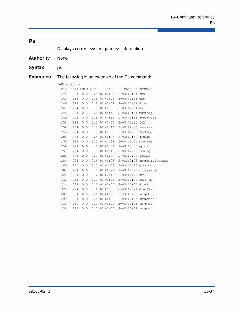
13–Command Reference
Ps
59263-02 B 13-87
PsDisplays current system process information.
Authority None
Syntax ps
Examples The following is an example of the Ps command:
SANbox #> ps
PID PPID %CPU %MEM TIME ELAPSED COMMAND
244 224 0.0 0.3 00:00:04 2-03:02:31 cns
245 224 0.0 0.3 00:00:06 2-03:02:31 ens
246 224 0.0 0.3 00:00:09 2-03:02:31 dlog
247 224 0.0 0.6 00:00:33 2-03:02:31 ds
248 224 0.3 2.8 00:09:59 2-03:02:31 mgmtApp
249 224 0.0 0.3 00:00:16 2-03:02:31 sys2swlog
251 224 0.0 0.4 00:00:06 2-03:02:30 fc2
252 224 0.0 0.6 00:00:16 2-03:02:30 nserver
253 224 0.0 0.8 00:00:08 2-03:02:30 PortApp
254 224 0.0 0.5 00:00:03 2-03:02:30 qfsApp
255 224 0.0 0.5 00:00:09 2-03:02:30 mserver
256 224 0.0 0.7 00:00:06 2-03:02:30 eport
257 224 0.0 0.6 00:00:13 2-03:02:30 zoning
282 254 0.0 0.5 00:00:00 2-03:02:26 qfsApp
284 224 0.0 0.6 00:00:08 2-03:02:26 snmpservicepath
285 282 0.0 0.5 00:00:00 2-03:02:26 qfsApp
308 224 0.0 0.8 00:00:29 2-03:02:25 cim_server
322 224 0.0 0.7 00:00:16 2-03:02:24 util
323 224 0.0 0.4 00:00:09 2-03:02:24 port_mon
324 224 0.0 0.5 00:00:07 2-03:02:24 diagAgent
325 224 0.0 0.4 00:00:03 2-03:02:24 diagExec
289 224 0.0 0.4 00:00:00 2-03:02:25 snmpd
290 224 0.0 0.5 00:00:00 2-03:02:25 snmpmain
335 290 0.0 0.5 00:00:00 2-03:02:23 snmpmain
336 335 0.0 0.5 00:00:00 2-03:02:23 snmpmain
13–Command Reference
Quit
13-88 59263-02 B
QuitCloses the Telnet session.
Authority None
Syntax quit
Notes You can also press Control-D to close the Telnet session.
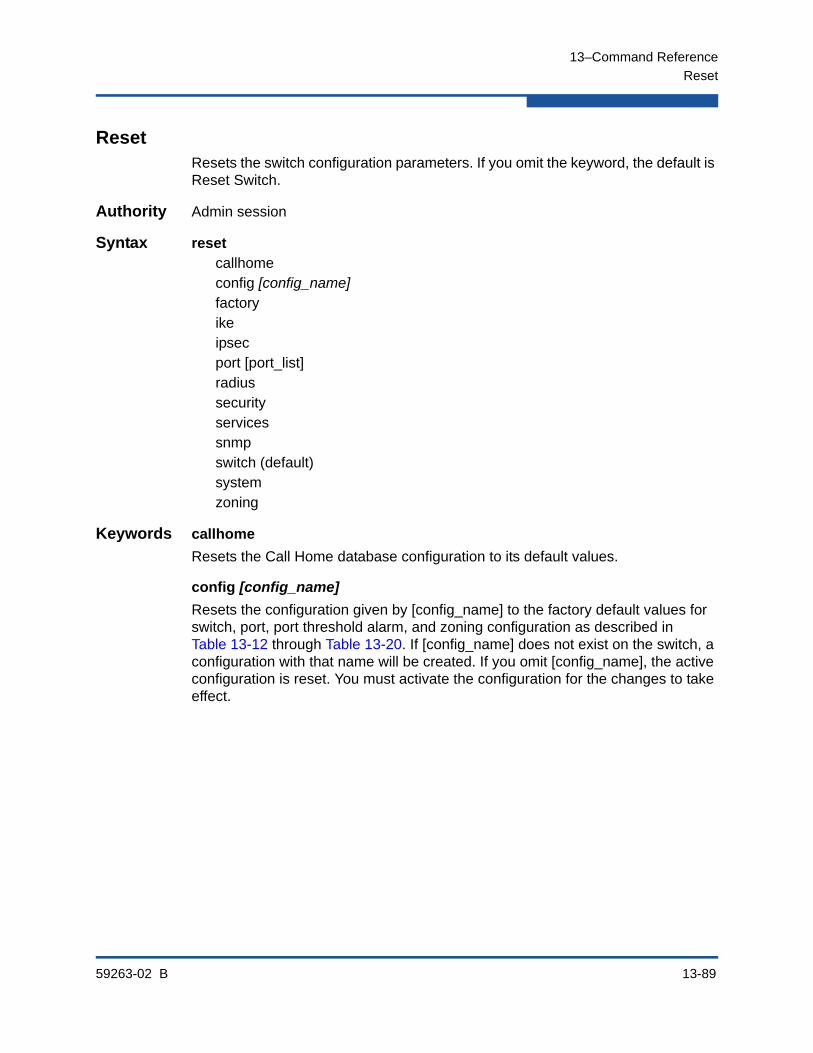
13–Command Reference
Reset
59263-02 B 13-89
ResetResets the switch configuration parameters. If you omit the keyword, the default is Reset Switch.
Authority Admin session
Syntax resetcallhomeconfig [config_name]factoryikeipsecport [port_list]radiussecurityservicessnmpswitch (default)systemzoning
Keywords callhome
Resets the Call Home database configuration to its default values.
config [config_name]
Resets the configuration given by [config_name] to the factory default values for switch, port, port threshold alarm, and zoning configuration as described in Table 13-12 through Table 13-20. If [config_name] does not exist on the switch, a configuration with that name will be created. If you omit [config_name], the active configuration is reset. You must activate the configuration for the changes to take effect.

13–Command Reference
Reset
13-90 59263-02 B
factory
Resets switch configuration, port configuration, port threshold alarm configuration, zoning configuration, SNMP configuration, system configuration, security configuration, RADIUS configuration, switch services configuration, zoning configuration, and Call Home configuration to the factory default values as described in Table 13-12 through Table 13-20. The switch configuration is activated automatically.
ike
Resets the IKE database configuration, removing all IKE peers and policies.
ipsec
Resets the IP security database and IKE database configurations, removing all IP security associations, IP security policies, IKE peers, and IKE policies.
port [port_list]
Reinitializes one or more ports given by [port_list]. [port_list] can be a set of port numbers and ranges delimited by spaces. For example, [0 2 10-15] specifies ports 0, 2, 10, 11, 12, 13, 14, and 15.
radius
Resets the RADIUS configuration to the default values as described in Table 13-17.
security
Clears the security database and deactivates the active security set. The security configuration value, autosave, and fabric binding remain unchanged.
services
Resets the switch services configuration to the default values as described in Table 13-18.
snmp
Resets the SNMP configuration settings to the factory default values. Refer to Table 13-16 for SNMP configuration default values.
NOTE:
Because this keyword changes network parameters, the workstation could lose communication with the switch and release the Admin session.
This keyword does not affect installed license keys.

13–Command Reference
Reset
59263-02 B 13-91
switch
Resets the switch without a power-on self test. This is the default. This reset disrupts traffic and does the following:
Activates the pending firmware.
Closes all management sessions.
Clears the event log. To save the event log before resetting, refer to the “Set Log” command on page 13-121.
To reset the switch with a power-on self test, refer to the “Hardreset” command on page 13-40. To reset the switch without disrupting traffic, refer to the “Hotreset” command on page 13-43.
system
Resets the system configuration settings to the factory default values as described in Table 13-19.
zoning
Clears the zoning database and deactivates the active zone set. The zoning configuration parameters (MergeAutoSave, DefaultZone, DiscardInactive) remain unchanged. Refer to Table 13-15 for information about the zoning configuration parameters.
NOTE:
The following files are deleted from the switch during a switch reset:
Firmware image files that have not been unpacked
Configuration backup files
Support files
NOTE:
Because this keyword changes network parameters, the workstation could lose communication with the switch.
This keyword does not affect installed license keys.
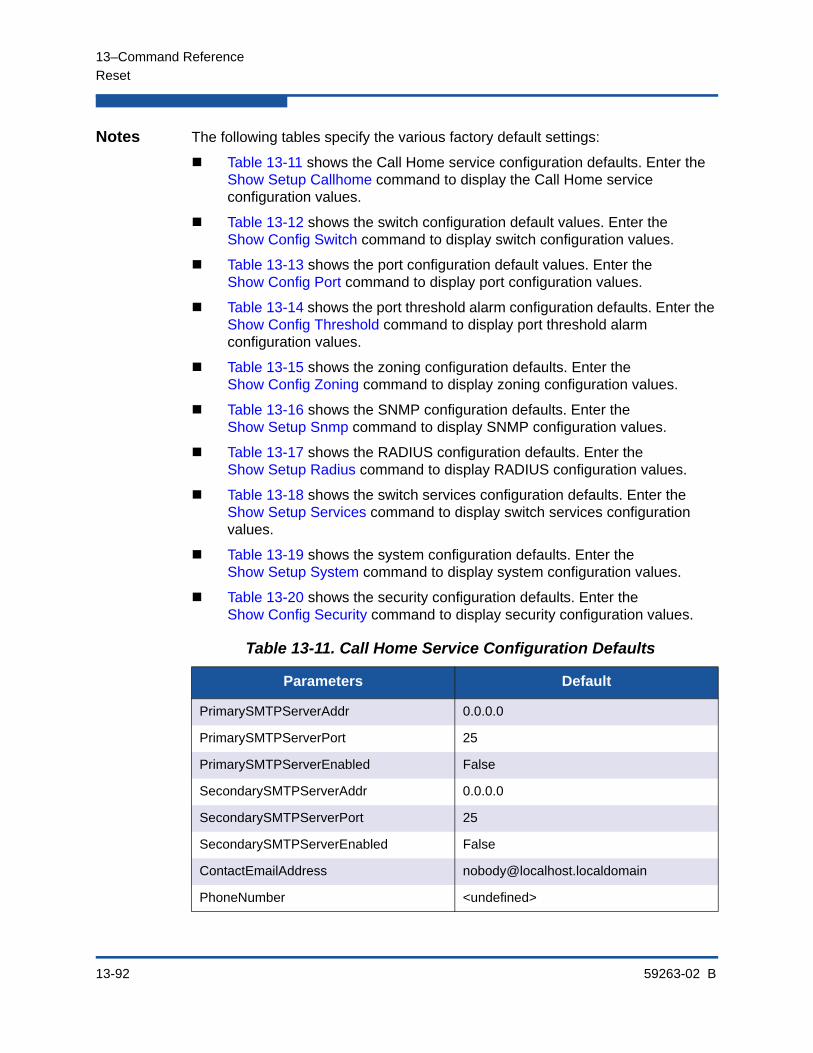
13–Command Reference
Reset
13-92 59263-02 B
Notes The following tables specify the various factory default settings:
Table 13-11 shows the Call Home service configuration defaults. Enter the Show Setup Callhome command to display the Call Home service configuration values.
Table 13-12 shows the switch configuration default values. Enter the Show Config Switch command to display switch configuration values.
Table 13-13 shows the port configuration default values. Enter the Show Config Port command to display port configuration values.
Table 13-14 shows the port threshold alarm configuration defaults. Enter the Show Config Threshold command to display port threshold alarm configuration values.
Table 13-15 shows the zoning configuration defaults. Enter the Show Config Zoning command to display zoning configuration values.
Table 13-16 shows the SNMP configuration defaults. Enter the Show Setup Snmp command to display SNMP configuration values.
Table 13-17 shows the RADIUS configuration defaults. Enter the Show Setup Radius command to display RADIUS configuration values.
Table 13-18 shows the switch services configuration defaults. Enter the Show Setup Services command to display switch services configuration values.
Table 13-19 shows the system configuration defaults. Enter the Show Setup System command to display system configuration values.
Table 13-20 shows the security configuration defaults. Enter the Show Config Security command to display security configuration values.
Table 13-11. Call Home Service Configuration Defaults
Parameters Default
PrimarySMTPServerAddr 0.0.0.0
PrimarySMTPServerPort 25
PrimarySMTPServerEnabled False
SecondarySMTPServerAddr 0.0.0.0
SecondarySMTPServerPort 25
SecondarySMTPServerEnabled False
ContactEmailAddress [email protected]
PhoneNumber <undefined>
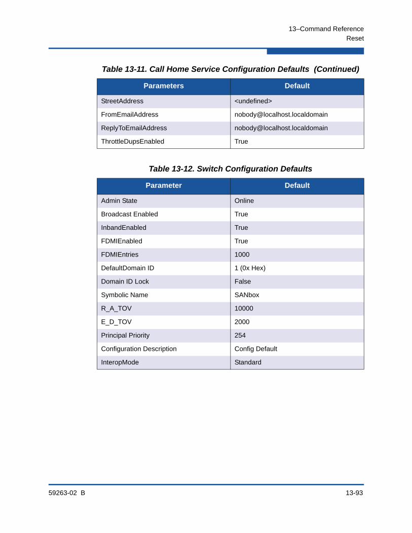
13–Command Reference
Reset
59263-02 B 13-93
StreetAddress <undefined>
FromEmailAddress [email protected]
ReplyToEmailAddress [email protected]
ThrottleDupsEnabled True
Table 13-12. Switch Configuration Defaults
Parameter Default
Admin State Online
Broadcast Enabled True
InbandEnabled True
FDMIEnabled True
FDMIEntries 1000
DefaultDomain ID 1 (0x Hex)
Domain ID Lock False
Symbolic Name SANbox
R_A_TOV 10000
E_D_TOV 2000
Principal Priority 254
Configuration Description Config Default
InteropMode Standard
Table 13-11. Call Home Service Configuration Defaults (Continued)
Parameters Default

13–Command Reference
Reset
13-94 59263-02 B
Table 13-13. Port Configuration Defaults
Parameter SFP Port Defaults XPAK Port Defaults
Admin State Online Online
Link Speed Auto 10-Gbps
Port Type GL G
Symbolic Name Portn, where n is the port number
10G-n, where n is the port number
ALFairness False N/A
DeviceScanEnabled True True
ForceOfflineRSCN False False
ARB_FF False N/A
InteropCredit 0 0
ExtCredit 0 N/A
FANEnable True N/A
AutoPerfTuning True True
LCFEnable False False
MFSEnable False False
MSEnable True False
NoClose False N/A
IOStreamGuard Auto Auto
VIEnable False False
PDISCPingEnable True N/A
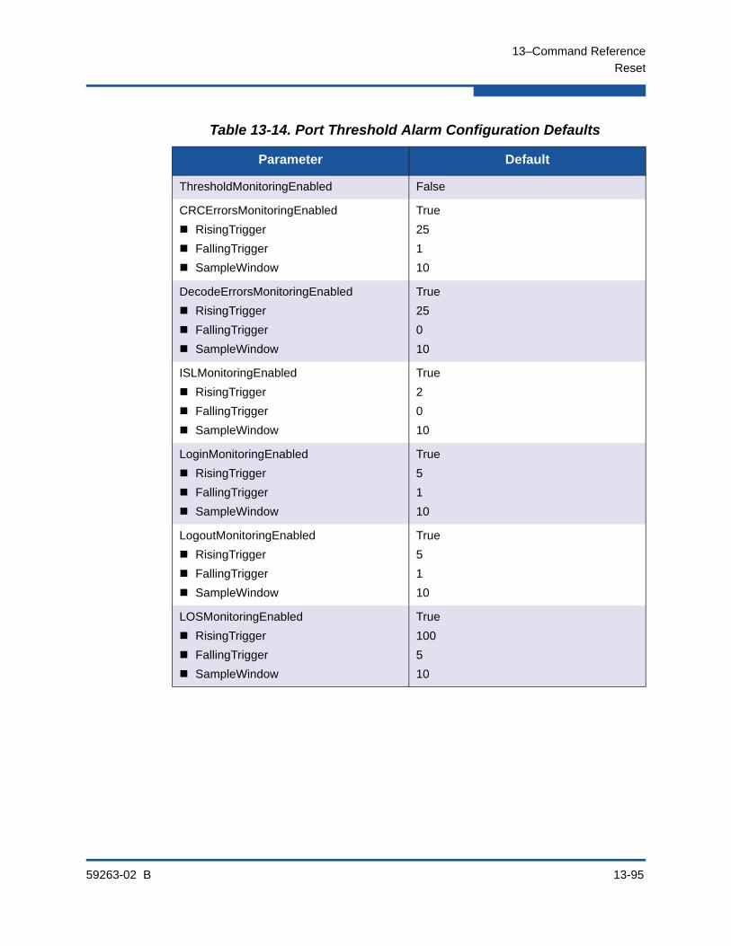
13–Command Reference
Reset
59263-02 B 13-95
Table 13-14. Port Threshold Alarm Configuration Defaults
Parameter Default
ThresholdMonitoringEnabled False
CRCErrorsMonitoringEnabled
RisingTrigger
FallingTrigger
SampleWindow
True
25
1
10
DecodeErrorsMonitoringEnabled
RisingTrigger
FallingTrigger
SampleWindow
True
25
0
10
ISLMonitoringEnabled
RisingTrigger
FallingTrigger
SampleWindow
True
2
0
10
LoginMonitoringEnabled
RisingTrigger
FallingTrigger
SampleWindow
True
5
1
10
LogoutMonitoringEnabled
RisingTrigger
FallingTrigger
SampleWindow
True
5
1
10
LOSMonitoringEnabled
RisingTrigger
FallingTrigger
SampleWindow
True
100
5
10

13–Command Reference
Reset
13-96 59263-02 B
Table 13-15. Zoning Configuration Defaults
Parameter Default
MergeAutoSave True
DefaultZone Allow
DiscardInactive False
Table 13-16. SNMP Configuration Defaults
Parameter Default
SNMPEnabled True
Contact <syscontact undefined>
Location <sysLocation undefined>
Description QLogic 5800V FC Switch
ObjectID 1.3.6.1.4.1.3873.1.14 (5800V)
1.3.6.1.4.1.3873.1.9 (5802V)
AuthFailureTrap False
ProxyEnabled True
SNMPv3Enabled False
Trap [1-5] Address Trap 1: 10.0.0.254; Traps 2–5: 0.0.0.0
Trap [1-5] Port 162
Trap [1-5] Severity Warning
Trap [1-5] Version 2
Trap [1-5] Enabled False
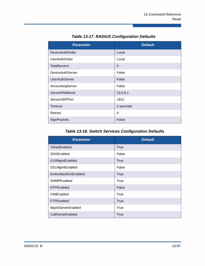
13–Command Reference
Reset
59263-02 B 13-97
Table 13-17. RADIUS Configuration Defaults
Parameter Default
DeviceAuthOrder Local
UserAuthOrder Local
TotalServers 0
DeviceAuthServer False
UserAuthServer False
AccountingServer False
ServerIPAddress 10.0.0.1
ServerUDPPort 1812
Timeout 2 seconds
Retries 0
SignPackets False
Table 13-18. Switch Services Configuration Defaults
Parameter Default
TelnetEnabled True
SSHEnabled False
GUIMgmtEnabled True
SSLMgmtEnabled False
EmbeddedGUIEnabled True
SNMPEnabled True
NTPEnabled False
CIMEnabled True
FTPEnabled True.
MgmtServerEnabled True
CallHomeEnabled True
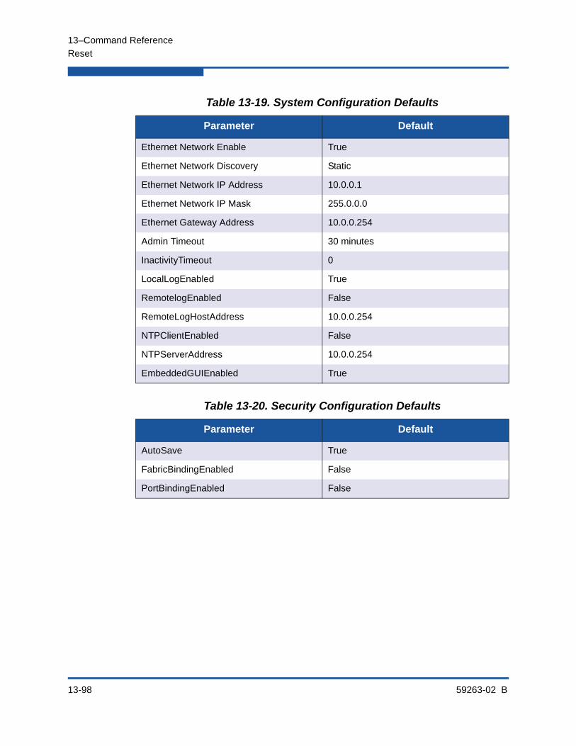
13–Command Reference
Reset
13-98 59263-02 B
Table 13-19. System Configuration Defaults
Parameter Default
Ethernet Network Enable True
Ethernet Network Discovery Static
Ethernet Network IP Address 10.0.0.1
Ethernet Network IP Mask 255.0.0.0
Ethernet Gateway Address 10.0.0.254
Admin Timeout 30 minutes
InactivityTimeout 0
LocalLogEnabled True
RemotelogEnabled False
RemoteLogHostAddress 10.0.0.254
NTPClientEnabled False
NTPServerAddress 10.0.0.254
EmbeddedGUIEnabled True
Table 13-20. Security Configuration Defaults
Parameter Default
AutoSave True
FabricBindingEnabled False
PortBindingEnabled False
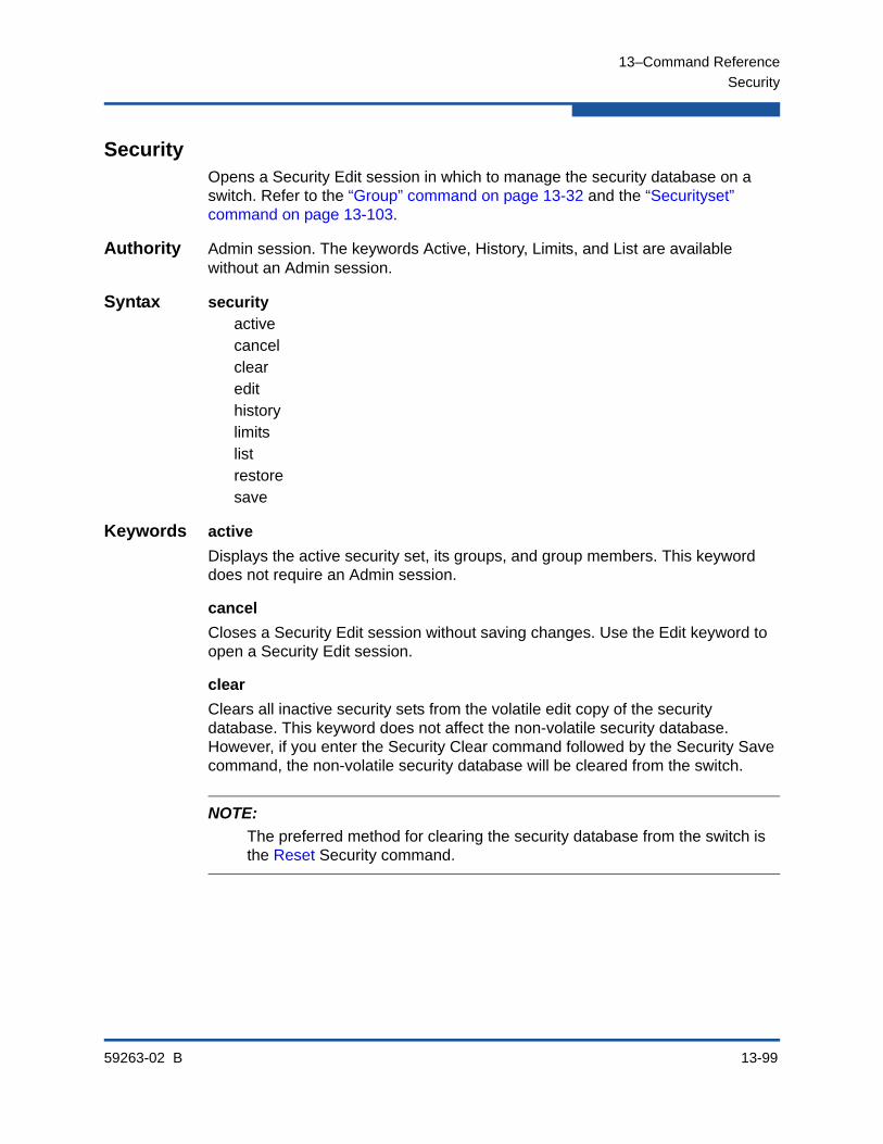
13–Command Reference
Security
59263-02 B 13-99
SecurityOpens a Security Edit session in which to manage the security database on a switch. Refer to the “Group” command on page 13-32 and the “Securityset” command on page 13-103.
Authority Admin session. The keywords Active, History, Limits, and List are available without an Admin session.
Syntax securityactivecancelclearedithistorylimitslistrestoresave
Keywords active
Displays the active security set, its groups, and group members. This keyword does not require an Admin session.
cancel
Closes a Security Edit session without saving changes. Use the Edit keyword to open a Security Edit session.
clear
Clears all inactive security sets from the volatile edit copy of the security database. This keyword does not affect the non-volatile security database. However, if you enter the Security Clear command followed by the Security Save command, the non-volatile security database will be cleared from the switch.
NOTE:
The preferred method for clearing the security database from the switch is the Reset Security command.

13–Command Reference
Security
13-100 59263-02 B
edit
Initiates a Security Edit session in which to make changes to the security database. A Security Edit session enables you to use the Group and Securityset commands to create, add, and delete security sets, groups, and group members. To close a Security Edit session and save changes, enter the Security Save command. To close a Security Edit session without saving changes, enter the Security Cancel command.
history
Displays history information about the security database and the active security set, including the account name that made changes and when those changes were made. This keyword does not require an Admin session.
limits
Displays the current totals and the security database limits for the number of security sets, groups, members per group, and total members. This keyword does not require an Admin session.
list
Displays all security sets, groups, and group members in the security database. This keyword does not require an Admin session.
restore
Restores the volatile security database with the contents of the non-volatile security database. If the AutoSave parameter is False, you can use this keyword to revert changes to the volatile security database that were propagated from another switch in the fabric through security set activation or merging fabrics. Refer to Table 13-20 for information about the AutoSave parameter.
save
Saves the changes that have been made to the security database during a Security Edit session. Changes you make to any security set will not take effect until you activate that security set. Refer to the “Securityset” command on page 13-103 for information about activating a security set.

13–Command Reference
Security
59263-02 B 13-101
Examples The following is an example of the Security Active command:
SANbox #> security active
Active Security Information
SecuritySet Group GroupMember
----------- ----- -----------
alpha
group1 (ISL)
10:00:00:00:00:10:21:16
Authentication Chap
Primary Hash MD5
Primary Secret ********
Secondary Hash SHA-1
Secondary Secret ********
Binding 0
10:00:00:00:00:10:21:17
Authentication Chap
Primary Hash MD5
Primary Secret ********
Secondary Hash SHA-1
Secondary Secret ********
Binding 0
The following is an example of the Security History command:
SANbox #> security history
Active Database Information
---------------------------
SecuritySetLastActivated/DeactivatedBy Remote
SecuritySetLastActivated/DeactivatedOn day month date time year
Database Checksum 00000000
Inactive Database Information
-----------------------------
ConfigurationLastEditedBy admin@IB-session11
ConfigurationLastEditedOn day month date time year
Database Checksum 00007558
The following is an example of the Security Limits command:
SANbox #> security limits
Security Attribute Maximum Current [Name]
------------------ ------- ------- ------
MaxSecuritySets 4 1
MaxGroups 16 2
MaxTotalMembers 1000 19
MaxMembersPerGroup 1000
4 group1
15 group2
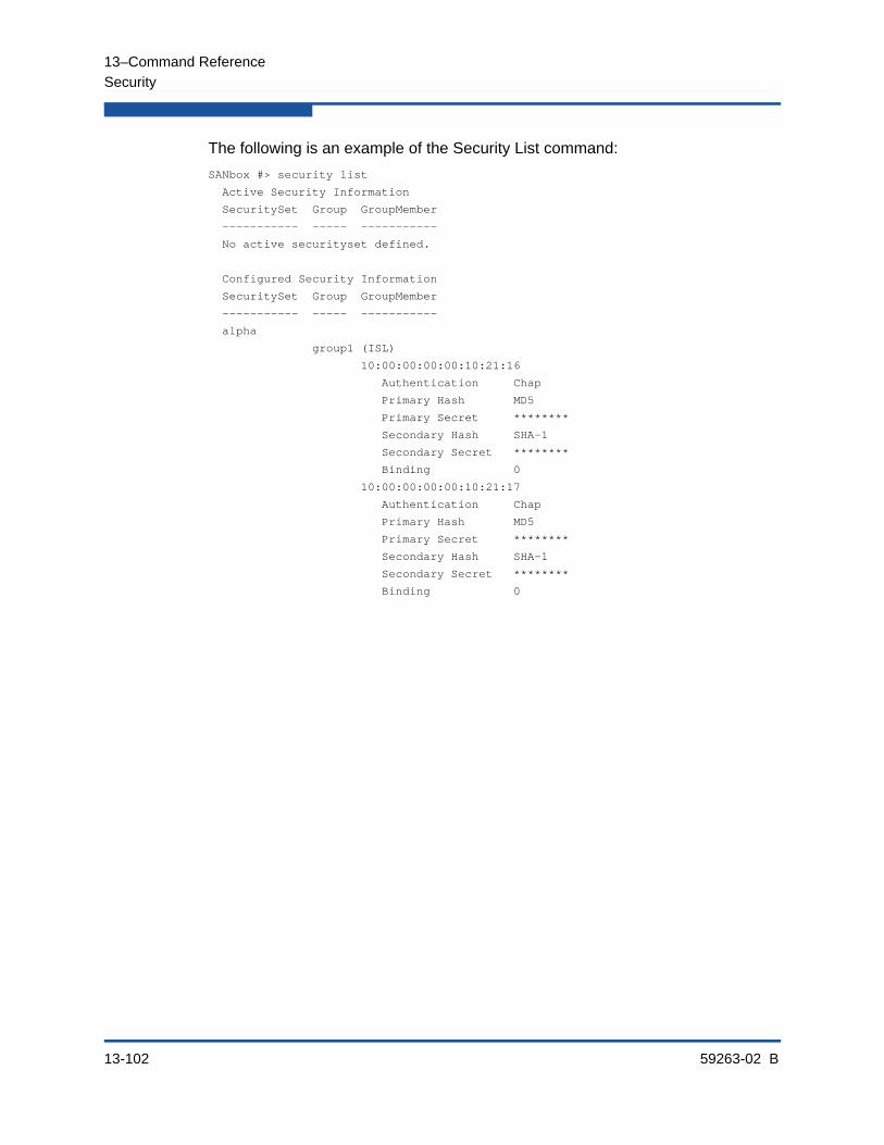
13–Command Reference
Security
13-102 59263-02 B
The following is an example of the Security List command:
SANbox #> security list
Active Security Information
SecuritySet Group GroupMember
----------- ----- -----------
No active securityset defined.
Configured Security Information
SecuritySet Group GroupMember
----------- ----- -----------
alpha
group1 (ISL)
10:00:00:00:00:10:21:16
Authentication Chap
Primary Hash MD5
Primary Secret ********
Secondary Hash SHA-1
Secondary Secret ********
Binding 0
10:00:00:00:00:10:21:17
Authentication Chap
Primary Hash MD5
Primary Secret ********
Secondary Hash SHA-1
Secondary Secret ********
Binding 0

13–Command Reference
Securityset
59263-02 B 13-103
SecuritysetManages security sets in the security database.
Authority Admin session and a Security Edit session. Refer to the “Security” command on page 13-99 for information about starting a Security Edit session. The Active, Groups, and List keywords are available without an Admin session. You must close the Security Edit session before using the Activate and Deactivate keywords.
Syntax securitysetactivate [security_set]activeadd [security_set] [group_list]copy [security_set_source] [security_set_destination]create [security_set]deactivatedelete [security_set]groups [security_set]listremove [security_set] [group]rename [security_set_old] [security_set_new]
Keywords activate [security_set]
Activates the security set given by [security_set] and deactivates the currently active security set. Close the Security Edit session using the Security Save or Security Cancel command before using this keyword.
active
Displays the name of the active security set. This keyword is available to without an Admin session.
add [security_set] [group_list]
Adds one or more groups given by [group_list] to the security set given by [security_set]. Use a <space> to delimit multiple group names in [group_list]. A security set can have a maximum of three groups, but no more than one group of each group type.
copy [security_set_source] [security_set_destination]
Creates a new security set named [security_set_destination] and copies into it the membership from the security set given by [security_set_source].
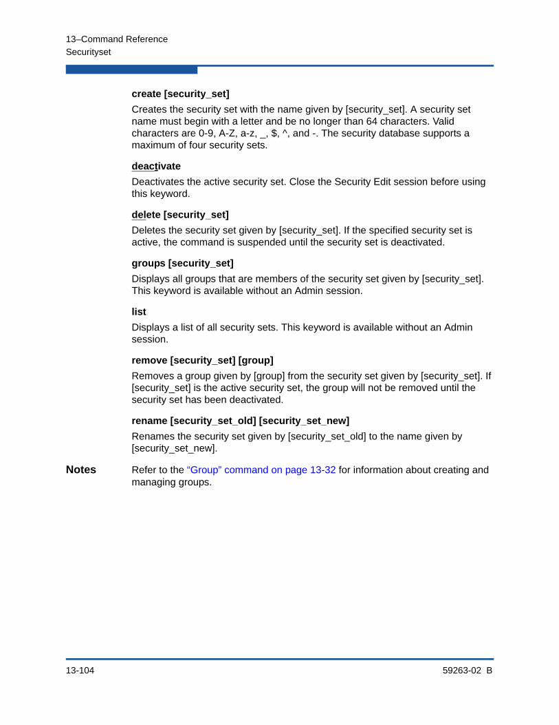
13–Command Reference
Securityset
13-104 59263-02 B
create [security_set]
Creates the security set with the name given by [security_set]. A security set name must begin with a letter and be no longer than 64 characters. Valid characters are 0-9, A-Z, a-z, _, $, ^, and -. The security database supports a maximum of four security sets.
deactivate
Deactivates the active security set. Close the Security Edit session before using this keyword.
delete [security_set]
Deletes the security set given by [security_set]. If the specified security set is active, the command is suspended until the security set is deactivated.
groups [security_set]
Displays all groups that are members of the security set given by [security_set]. This keyword is available without an Admin session.
list
Displays a list of all security sets. This keyword is available without an Admin session.
remove [security_set] [group]
Removes a group given by [group] from the security set given by [security_set]. If [security_set] is the active security set, the group will not be removed until the security set has been deactivated.
rename [security_set_old] [security_set_new]
Renames the security set given by [security_set_old] to the name given by [security_set_new].
Notes Refer to the “Group” command on page 13-32 for information about creating and managing groups.

13–Command Reference
Securityset
59263-02 B 13-105
Examples The following is an example of the Securityset Active command
SANbox #> securityset active
Active SecuritySet Information
------------------------------
ActiveSecuritySet alpha
LastActivatedBy Remote
LastActivatedOn day month date time year
The following is an example of the Securityset Groups command
SANbox #> securityset groups alpha
Current list of Groups for SecuritySet: alpha
---------------------------------------
group1 (ISL)
group2 (Port)
The following is an example of the Securityset List command
SANbox #> securityset list
Current list of SecuritySets
----------------------------
alpha
beta
13–Command Reference
Set Alarm
13-106 59263-02 B
Set AlarmControls the display of alarms in the session output stream or clears the alarm log.
Authority Admin session for the Clear keyword. Otherwise, none.
Syntax set alarm [option]
Keywords [option][option] can be one of the following:
clear
Clears the alarm log history. This value requires an Admin session.
on
Enables the display of alarms in the session output stream.
off
Disables the display of alarms in the session output stream. Disabling the display of alarms in the output stream allows command scripts to run without interruption.
Examples The following is an example of the Set Alarm command:
SANbox #> set alarm on
13–Command Reference
Set Beacon
59263-02 B 13-107
Set BeaconEnables or disables the flashing of the Logged-In LEDs for the purpose of locating a switch.
Authority None
Syntax set beacon [state]
Keywords [state]
[state] can be one of the following:
on
Enables the flashing beacon.
off
Disables the flashing beacon.
Examples The following is an example of the Set Beacon command:
SANbox #> set beacon on
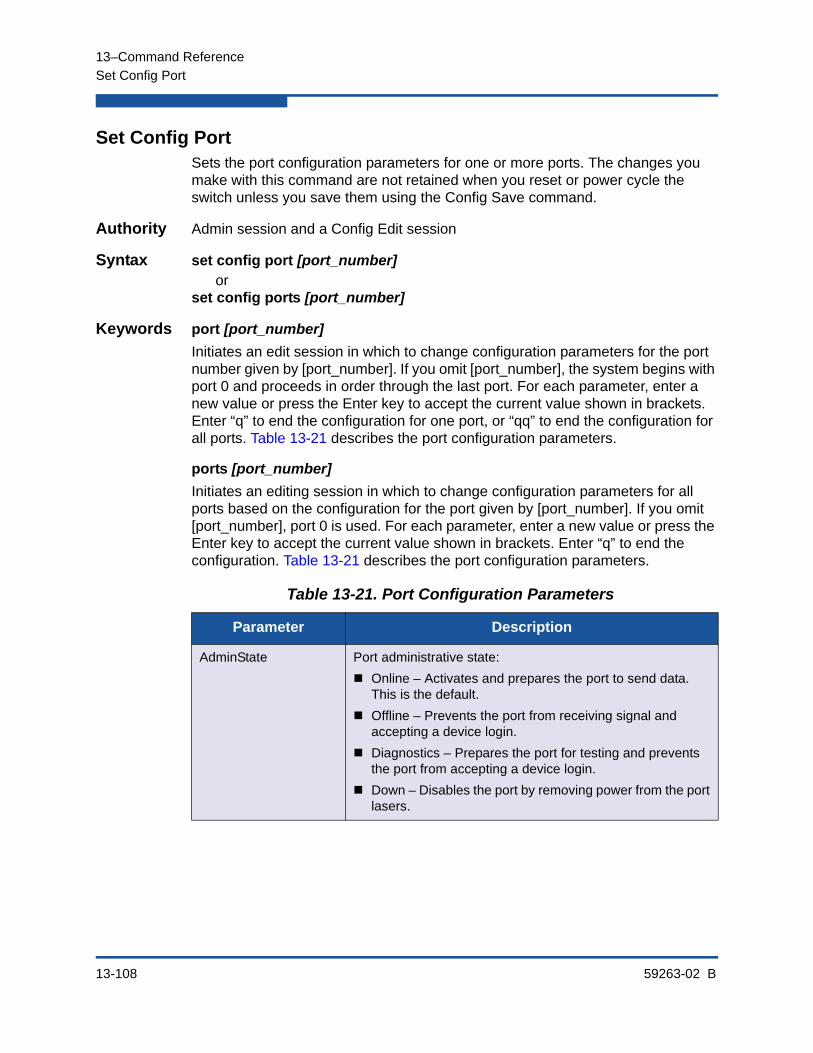
13–Command Reference
Set Config Port
13-108 59263-02 B
Set Config PortSets the port configuration parameters for one or more ports. The changes you make with this command are not retained when you reset or power cycle the switch unless you save them using the Config Save command.
Authority Admin session and a Config Edit session
Syntax set config port [port_number]or
set config ports [port_number]
Keywords port [port_number]
Initiates an edit session in which to change configuration parameters for the port number given by [port_number]. If you omit [port_number], the system begins with port 0 and proceeds in order through the last port. For each parameter, enter a new value or press the Enter key to accept the current value shown in brackets. Enter “q” to end the configuration for one port, or “qq” to end the configuration for all ports. Table 13-21 describes the port configuration parameters.
ports [port_number]
Initiates an editing session in which to change configuration parameters for all ports based on the configuration for the port given by [port_number]. If you omit [port_number], port 0 is used. For each parameter, enter a new value or press the Enter key to accept the current value shown in brackets. Enter “q” to end the configuration. Table 13-21 describes the port configuration parameters.
Table 13-21. Port Configuration Parameters
Parameter Description
AdminState Port administrative state:
Online – Activates and prepares the port to send data. This is the default.
Offline – Prevents the port from receiving signal and accepting a device login.
Diagnostics – Prepares the port for testing and prevents the port from accepting a device login.
Down – Disables the port by removing power from the port lasers.

13–Command Reference
Set Config Port
59263-02 B 13-109
LinkSpeed Transmission speed:
SFP Ports: 1-Gbps, 2 Gbps, 4-Gbps, 8-Gbps, or Auto. The default is Auto. 8-Gbps SFPs do not support the 1-Gbps setting. Setting a port to 1-Gbps that has an 8-Gbps SFP will down the port.
XPAK Ports: 10-Gbps, 20-Gbps, or Auto. The default is Auto.
PortType Port types:
SFP Ports: GL, G, F, FL, TR, Donor. The default is GL.
XPAK Ports: GL, G, F, FL, Donor. The default is GL.
SymbolicPortName Descriptive name for the port. The name can be up to 32 characters excluding #, semicolon (;), and comma (,). The default is Port n, where n is the port number.
ALFairness
(SFP ports only)
Arbitration loop fairness. Enables (True) or disables (False) the switch’s priority to arbitrate on the loop. The default is False.
DeviceScanEnabled Enables (True) or disables (False) the scanning of the con-nected device for FC-4 descriptor information during login. The default is True.
ForceOfflineRSCN Enables (False) or disables (True) the immediate transmis-sion of RSCN messages when communication between a port and a device is interrupted. If enabled, the RSCN mes-sage is delayed for 200 ms for locally attached devices and 400 ms for devices connected through other switches. The default is False. This parameter is ignored if IOStreamGuard is enabled.
ARB_FF Send ARB_FF (True) instead of IDLEs (False) on the loop. The default is False.
InteropCredit Interoperability credit. The number of buffer-to-buffer credits per port. 0 means the default is unchanged. Default buf-fer-to-buffer credits are 16 per port.
Changing interoperability credits is necessary only for E_Ports that are connected to non-FC-SW-2-compliant switches. Contact your authorized maintenance provider for assistance in using this feature.
Table 13-21. Port Configuration Parameters (Continued)
Parameter Description
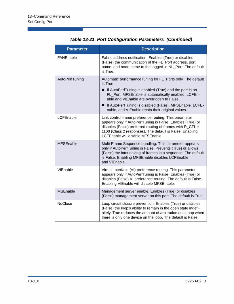
13–Command Reference
Set Config Port
13-110 59263-02 B
FANEnable Fabric address notification. Enables (True) or disables (False) the communication of the FL_Port address, port name, and node name to the logged-in NL_Port. The default is True.
AutoPerfTuning Automatic performance tuning for FL_Ports only. The default is True.
If AutoPerfTuning is enabled (True) and the port is an FL_Port, MFSEnable is automatically enabled. LCFEn-able and VIEnable are overridden to False.
If AutoPerfTuning is disabled (False), MFSEnable, LCFE-nable, and VIEnable retain their original values.
LCFEnable Link control frame preference routing. This parameter appears only if AutoPerfTuning is False. Enables (True) or disables (False) preferred routing of frames with R_CTL = 1100 (Class 2 responses). The default is False. Enabling LCFEnable will disable MFSEnable.
MFSEnable Multi-Frame Sequence bundling. This parameter appears only if AutoPerfTuning is False. Prevents (True) or allows (False) the interleaving of frames in a sequence. The default is False. Enabling MFSEnable disables LCFEnable and VIEnable.
VIEnable Virtual Interface (VI) preference routing. This parameter appears only if AutoPerfTuning is False. Enables (True) or disables (False) VI preference routing. The default is False. Enabling VIEnable will disable MFSEnable.
MSEnable Management server enable. Enables (True) or disables (False) management server on this port. The default is True.
NoClose Loop circuit closure prevention. Enables (True) or disables (False) the loop’s ability to remain in the open state indefi-nitely. True reduces the amount of arbitration on a loop when there is only one device on the loop. The default is False.
Table 13-21. Port Configuration Parameters (Continued)
Parameter Description
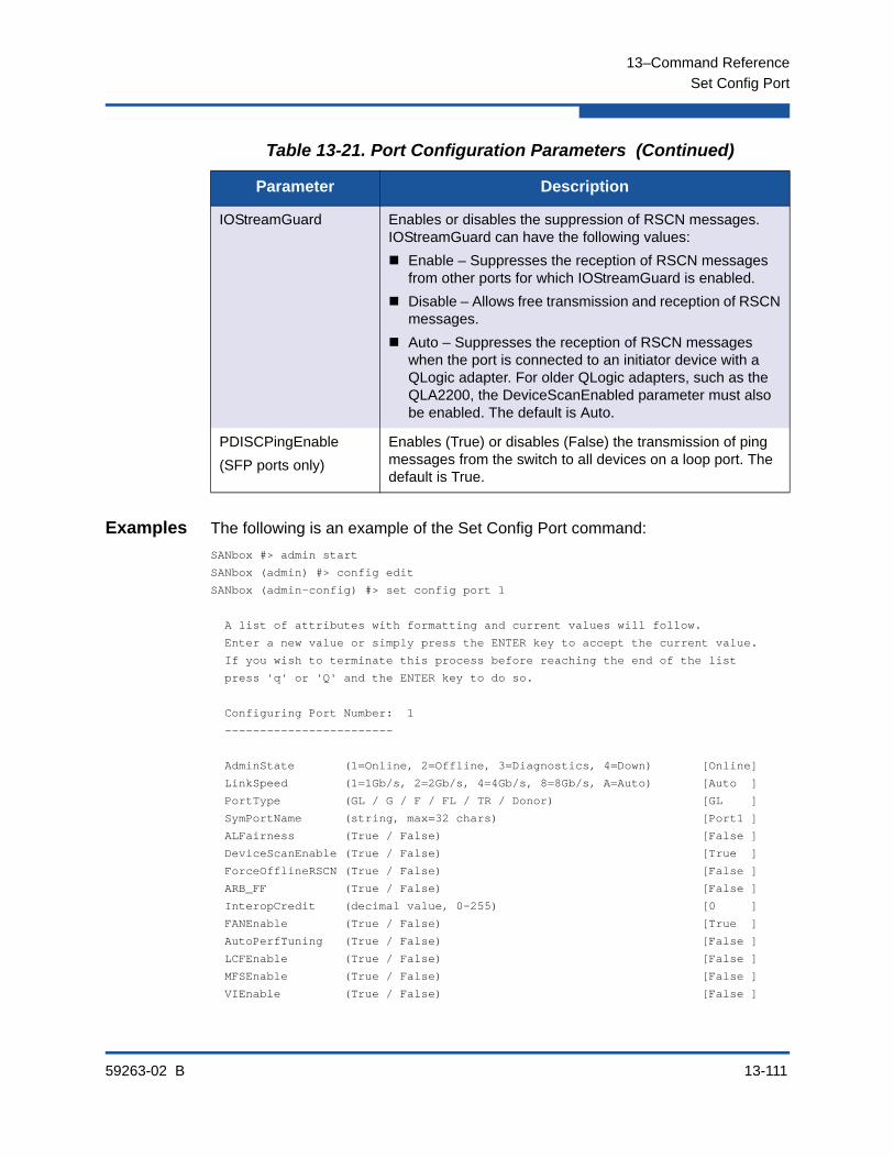
13–Command Reference
Set Config Port
59263-02 B 13-111
Examples The following is an example of the Set Config Port command:
SANbox #> admin start
SANbox (admin) #> config edit
SANbox (admin-config) #> set config port 1
A list of attributes with formatting and current values will follow.
Enter a new value or simply press the ENTER key to accept the current value.
If you wish to terminate this process before reaching the end of the list
press 'q' or 'Q' and the ENTER key to do so.
Configuring Port Number: 1
------------------------
AdminState (1=Online, 2=Offline, 3=Diagnostics, 4=Down) [Online]
LinkSpeed (1=1Gb/s, 2=2Gb/s, 4=4Gb/s, 8=8Gb/s, A=Auto) [Auto ]
PortType (GL / G / F / FL / TR / Donor) [GL ]
SymPortName (string, max=32 chars) [Port1 ]
ALFairness (True / False) [False ]
DeviceScanEnable (True / False) [True ]
ForceOfflineRSCN (True / False) [False ]
ARB_FF (True / False) [False ]
InteropCredit (decimal value, 0-255) [0 ]
FANEnable (True / False) [True ]
AutoPerfTuning (True / False) [False ]
LCFEnable (True / False) [False ]
MFSEnable (True / False) [False ]
VIEnable (True / False) [False ]
IOStreamGuard Enables or disables the suppression of RSCN messages. IOStreamGuard can have the following values:
Enable – Suppresses the reception of RSCN messages from other ports for which IOStreamGuard is enabled.
Disable – Allows free transmission and reception of RSCN messages.
Auto – Suppresses the reception of RSCN messages when the port is connected to an initiator device with a QLogic adapter. For older QLogic adapters, such as the QLA2200, the DeviceScanEnabled parameter must also be enabled. The default is Auto.
PDISCPingEnable
(SFP ports only)
Enables (True) or disables (False) the transmission of ping messages from the switch to all devices on a loop port. The default is True.
Table 13-21. Port Configuration Parameters (Continued)
Parameter Description

13–Command Reference
Set Config Port
13-112 59263-02 B
MSEnable (True / False) [True ]
NoClose (True / False) [False ]
IOStreamGuard (Enable / Disable / Auto) [Disable]
PDISCPingEnable (True / False) [True ]
Finished configuring attributes.
This configuration must be saved (see config save command) and
activated (see config activate command) before it can take effect.
To discard this configuration use the config cancel command.
The following is an example of the Set Config Port command for an XPAK port:
SANbox #> admin start
SANbox (admin) #> config edit
SANbox (admin-config) #> set config port 20
A list of attributes with formatting and current values will follow.
Enter a new value or simply press the ENTER key to accept the current value.
If you wish to terminate this process before reaching the end of the list
press 'q' or 'Q' and the ENTER key to do so.
Configuring Port Number: 20
------------------------
AdminState (1=Online, 2=Offline, 3=Diagnostics, 4=Down) [Online ]
LinkSpeed (10=10Gb/s) [10Gb/s ]
PortType (G / F) [G ]
SymPortName (string, max=32 chars) [10G-20 ]
DeviceScanEnable (True / False) [True ]
ForceOfflineRSCN (True / False) [False ]
AutoPerfTuning (True / False) [False ]
LCFEnable (True / False) [False ]
MFSEnable (True / False) [False ]
VIEnable (True / False) [False ]
MSEnable (True / False) [True ]
IOStreamGuard (Enable / Disable / Auto) [Auto ]
Finished configuring attributes.
This configuration must be saved (see config save command) and
activated (see config activate command) before it can take effect.
To discard this configuration use the config cancel command.
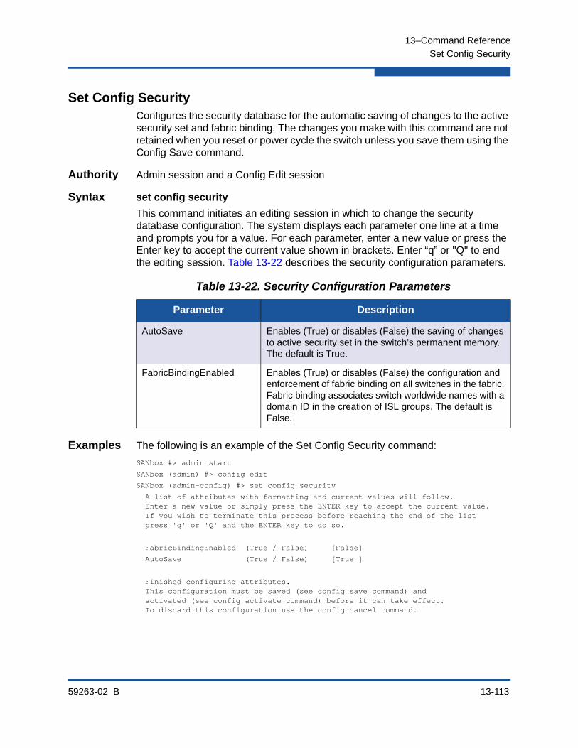
13–Command Reference
Set Config Security
59263-02 B 13-113
Set Config SecurityConfigures the security database for the automatic saving of changes to the active security set and fabric binding. The changes you make with this command are not retained when you reset or power cycle the switch unless you save them using the Config Save command.
Authority Admin session and a Config Edit session
Syntax set config security
This command initiates an editing session in which to change the security database configuration. The system displays each parameter one line at a time and prompts you for a value. For each parameter, enter a new value or press the Enter key to accept the current value shown in brackets. Enter “q” or "Q" to end the editing session. Table 13-22 describes the security configuration parameters.
Examples The following is an example of the Set Config Security command:
SANbox #> admin start
SANbox (admin) #> config edit
SANbox (admin-config) #> set config security
A list of attributes with formatting and current values will follow. Enter a new value or simply press the ENTER key to accept the current value. If you wish to terminate this process before reaching the end of the list press 'q' or 'Q' and the ENTER key to do so.
FabricBindingEnabled (True / False) [False]
AutoSave (True / False) [True ]
Finished configuring attributes. This configuration must be saved (see config save command) and activated (see config activate command) before it can take effect. To discard this configuration use the config cancel command.
Table 13-22. Security Configuration Parameters
Parameter Description
AutoSave Enables (True) or disables (False) the saving of changes to active security set in the switch’s permanent memory. The default is True.
FabricBindingEnabled Enables (True) or disables (False) the configuration and enforcement of fabric binding on all switches in the fabric. Fabric binding associates switch worldwide names with a domain ID in the creation of ISL groups. The default is False.

13–Command Reference
Set Config Security Portbinding
13-114 59263-02 B
Set Config Security PortbindingConfigures port binding.
Authority Admin session and a Config Edit session
Syntax set config security portbinding [port_number]
Keywords [port_number]Initiates an editing session in which to change the port binding configuration for the port given by [port_number]. The system displays each parameter one line at a time and prompts you for a value. For each parameter, enter a new value or press the Enter key to accept the current value shown in brackets. Enter “q” or "Q" to end the editing session. Table 13-23 describes the Set Config Security Portbinding parameters.
Examples The following is an example of the Set Config Security Portbinding command:
SANbox #> admin start
SANbox (admin) config edit
SANbox (admin-config) #> set config security portbinding 1
A list of attributes with formatting and current values will follow.
Enter a new value or simply press the ENTER key to accept the current value.
If you wish to terminate this process before reaching the end of the list
press 'q' or 'Q' and the ENTER key to do so.
PortBindingEnabled (True / False)[False] true
WWN (N=None / WWN)[None ] 10:00:00:c0:dd:00:b9:f9
WWN (N=None / WWN)[None ] 10:00:00:c0:dd:00:b9:f8
WWN (N=None / WWN)[None ] n
Finished configuring attributes.
This configuration must be saved (see config save command) and
activated (see config activate command) before it can take effect.
To discard this configuration use the config cancel command.
Table 13-23. Port Binding Configuration Parameters
Parameter Description
PortBindingEnabled Enables (True) or disables (False) port binding for the port given by [port_number].
WWN Worldwide port name for the port/device that is allowed to connect to the port given by [port_number].

13–Command Reference
Set Config Switch
59263-02 B 13-115
Set Config SwitchSets the switch configuration parameters. The changes you make with this command are not retained when you reset or power cycle the switch unless you save them using the Config Save command.
Authority Admin session and a Config Edit session
Syntax set config switchThis command initiates an editing session in which to change switch configuration settings. The system displays each parameter one line at a time and prompts you for a value. For each parameter, enter a new value or press the Enter key to accept the current value shown in brackets. Table 13-24 describes the switch configuration parameters.
Table 13-24. Switch Configuration Parameters
Parameter Description
AdminState Switch administrative state.
Online – Activates and prepares the ports to send data. This is the default.
Offline – Prevents the ports from receiving signal and accepting a device login.
Diagnostics – Prepares the ports for testing and prevents the ports from accepting a device login.
Down – Disables the ports by removing power from the port lasers.
BroadcastEnabled Broadcast. Enables (True) or disables (False) forwarding of broadcast frames. The default is True.
InbandEnabled Inband management. Enables (True) or disables (False) the ability to manage the switch over an ISL. The default is True.
FDMIEnabled Fabric Device Monitoring Interface. Enables (True) or dis-ables (False) the monitoring of target and initiator device information. The default is True.
FDMIEntries The number of device entries to maintain in the FDMI data-base. Enter a number from 0–1000. The default is 1000.
DefaultDomainID Default domain ID. The default is 1.
DomainIDLock Prevents (True) or allows (False) dynamic reassignment of the domain ID. The default is False.
SymbolicName Descriptive name for the switch. The name can be up to 32 characters excluding #, semicolon (;), and comma (,). The default is SANbox.

13–Command Reference
Set Config Switch
13-116 59263-02 B
Examples The following is an example of the Set Config Switch command:
SANbox #> admin start
SANbox (admin) #> config edit
SANbox (admin-config) #> set config switch
A list of attributes with formatting and default values will follow.
Enter a new value or simply press the ENTER key to accept the current value.
If you wish to terminate this process before reaching the end of the list
press 'q' or 'Q' and the ENTER key to do so.
AdminState (1=Online, 2=Offline, 3=Diagnostics) [Online ]
BroadcastEnabled (True / False) [True ]
InbandEnabled (True / False) [True ]
FDMIEnabled (True / False) [True ]
FDMIEntries (decimal value, 0-1000) [1000 ]
DefaultDomainID (decimal value, 1-239) [2 ]
DomainIDLock (True / False) [False ]
SymbolicName (string, max=32 chars) [SANbox ]
R_A_TOV (decimal value, 100-100000 msec) [10000 ]
E_D_TOV (decimal value, 10-20000 msec) [2000 ]
PrincipalPriority (decimal value, 1-255) [254 ]
ConfigDescription (string, max=64 chars) [Default Config]
R_A_TOV Resource Allocation Timeout Value. The number of millisec-onds the switch waits to allow two ports to allocate enough resources to establish a link. The default is 10000.
E_D_TOV Error Detect Timeout Value. The number of milliseconds a port is to wait for errors to clear. The default is 2000.
PrincipalPriority The priority used in the FC-SW-2 principal switch selection algorithm. 1 is high, 255 is low. The default is 254.
ConfigDescription Switch configuration description. The configuration descrip-tion can be up to 32 characters excluding #, semicolon (;), and comma (,). The default is Config Default.
Table 13-24. Switch Configuration Parameters (Continued)
Parameter Description

13–Command Reference
Set Config Threshold
59263-02 B 13-117
Set Config ThresholdSets the port alarm threshold parameters by which the switch monitors port performance and generates alarms. The changes you make with this command are not retained when you reset or power cycle the switch unless you save them using the Config Save command.
Authority Admin session and a Config Edit session
Syntax set config thresholdInitiates a configuration session by which to generate and log alarms for selected events. The system displays each event, its triggers, and a sampling window one line at a time and prompts you for a value. For each parameter, enter a new value or press the Enter key to accept the current value shown in brackets. Table 13-25 describes the port alarm threshold parameters.
Table 13-25. Port Alarm Threshold Parameters
Parameter Description
Threshold Monitoring Enabled Master enable/disable parameter for all events. Enables (True) or disables (False) the generation of all enabled event alarms. The default is False.
CRCErrorsMonitoringEnabled
DecodeErrorsMonitoringEnabled
ISLMonitoringEnabled
LoginMonitoringEnabled
LogoutMonitoringEnabled
LOSMonitoringEnabled
The event type enable/disable parameter. Enables (True) or disables (False) the generation of alarms for each of the following events:
CRC errors
Decode errors
ISL connection count
Device login errors
Device logout errors
Loss-of-signal errors
Rising Trigger The event count above which a rising trigger alarm is logged. The switch will not generate another ris-ing trigger alarm for that event until the count descends below the falling trigger and again exceeds the rising trigger.
Falling Trigger The event count below which a falling trigger alarm is logged. The switch will not generate another fall-ing trigger alarm for that event until the count exceeds the rising trigger and descends again below the falling trigger.
Sample Window The time in seconds in which to count events.

13–Command Reference
Set Config Threshold
13-118 59263-02 B
Notes The switch will down a port if an alarm condition is not cleared within three consecutive sampling windows (by default, 30 seconds). Reset the port to bring it back online. An alarm is cleared when the threshold monitoring detects that the error rate has fallen below the falling trigger.
Examples The following is an example of the Set Config Threshold command:
SANbox #> admin start
SANbox (admin) #> config edit
SANbox (admin-config) #> set config threshold
A list of attributes with formatting and current values will follow.
Enter a new value or simply press the ENTER key to accept the current value.
If you wish to terminate this process before reaching the end of the list
press 'q' or 'Q' and the ENTER key to do so.
ThresholdMonitoringEnabled (True / False) [False ]
CRCErrorsMonitoringEnabled (True / False) [True ]
RisingTrigger (decimal value, 1-1000) [25 ]
FallingTrigger (decimal value, 0-1000) [1 ]
SampleWindow (decimal value, 1-1000 sec) [10 ]
DecodeErrorsMonitoringEnabled (True / False) [True ]
RisingTrigger (decimal value, 1-1000) [25 ]
FallingTrigger (decimal value, 0-1000) [0 ]
SampleWindow (decimal value, 1-1000 sec) [10 ]
ISLMonitoringEnabled (True / False) [True ]
RisingTrigger (decimal value, 1-1000) [2 ]
FallingTrigger (decimal value, 0-1000) [0 ]
SampleWindow (decimal value, 1-1000 sec) [10 ]
LoginMonitoringEnabled (True / False) [True ]
RisingTrigger (decimal value, 1-1000) [5 ]
FallingTrigger (decimal value, 0-1000) [1 ]
SampleWindow (decimal value, 1-1000 sec) [10 ]
LogoutMonitoringEnabled (True / False) [True ]
RisingTrigger (decimal value, 1-1000) [5 ]
FallingTrigger (decimal value, 0-1000) [1 ]
SampleWindow (decimal value, 1-1000 sec) [10 ]
LOSMonitoringEnabled (True / False) [True ]
RisingTrigger (decimal value, 1-1000) [100 ]
FallingTrigger (decimal value, 0-1000) [5 ]
SampleWindow (decimal value, 1-1000 sec) [10 ]
Finished configuring attributes.This configuration must be saved (see config save command) and activated (see config activate command) before it can take effect.To discard this configuration use the config cancel command.
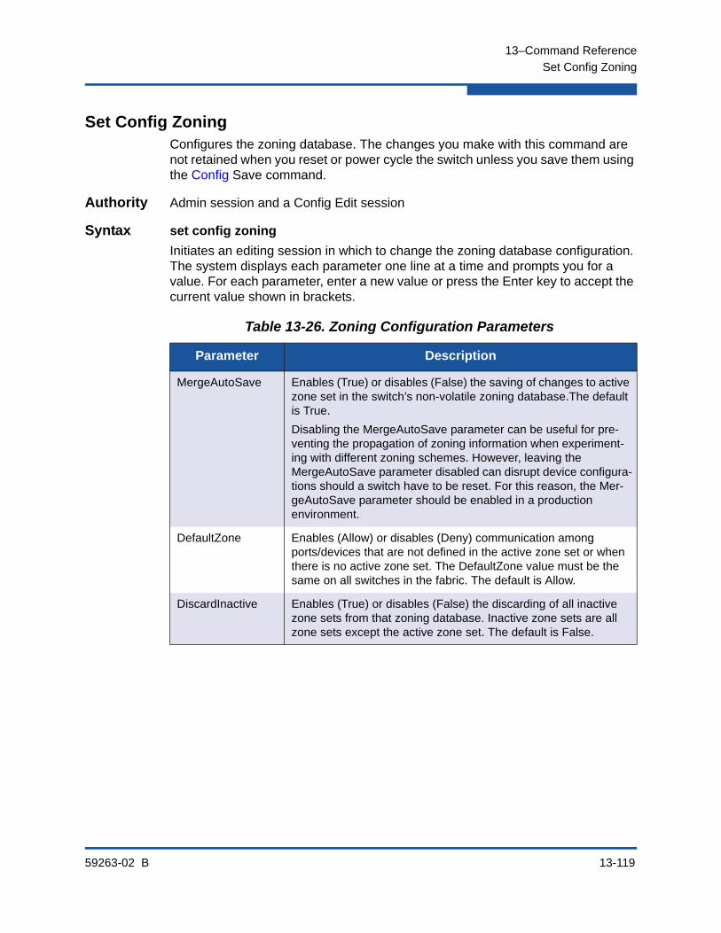
13–Command Reference
Set Config Zoning
59263-02 B 13-119
Set Config ZoningConfigures the zoning database. The changes you make with this command are not retained when you reset or power cycle the switch unless you save them using the Config Save command.
Authority Admin session and a Config Edit session
Syntax set config zoning
Initiates an editing session in which to change the zoning database configuration. The system displays each parameter one line at a time and prompts you for a value. For each parameter, enter a new value or press the Enter key to accept the current value shown in brackets.
Table 13-26. Zoning Configuration Parameters
Parameter Description
MergeAutoSave Enables (True) or disables (False) the saving of changes to active zone set in the switch’s non-volatile zoning database.The default is True.
Disabling the MergeAutoSave parameter can be useful for pre-venting the propagation of zoning information when experiment-ing with different zoning schemes. However, leaving the MergeAutoSave parameter disabled can disrupt device configura-tions should a switch have to be reset. For this reason, the Mer-geAutoSave parameter should be enabled in a production environment.
DefaultZone Enables (Allow) or disables (Deny) communication among ports/devices that are not defined in the active zone set or when there is no active zone set. The DefaultZone value must be the same on all switches in the fabric. The default is Allow.
DiscardInactive Enables (True) or disables (False) the discarding of all inactive zone sets from that zoning database. Inactive zone sets are all zone sets except the active zone set. The default is False.

13–Command Reference
Set Config Zoning
13-120 59263-02 B
Examples The following is an example of the Set Config Zoning command.
SANbox #> admin start
SANbox (admin) #> config edit
The config named default is being edited.
SANbox (admin-config) #> set config zoning
A list of attributes with formatting and current values will follow.
Enter a new value or simply press the ENTER key to accept the current value.
If you wish to terminate this process before reaching the end of the list press 'q' or 'Q' and the ENTER key to do so.
MergeAutoSave (True / False) [True ]
DefaultZone (Allow / Deny) [Allow ]
DiscardInactive (True / False) [False]
Finished configuring attributes.
This configuration must be saved (see config save command) and
activated (see config activate command) before it can take effect.
To discard this configuration use the config cancel command.
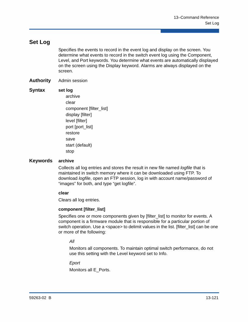
13–Command Reference
Set Log
59263-02 B 13-121
Set LogSpecifies the events to record in the event log and display on the screen. You determine what events to record in the switch event log using the Component, Level, and Port keywords. You determine what events are automatically displayed on the screen using the Display keyword. Alarms are always displayed on the screen.
Authority Admin session
Syntax set logarchiveclearcomponent [filter_list]display [filter]level [filter]port [port_list]restoresavestart (default)stop
Keywords archive
Collects all log entries and stores the result in new file named logfile that is maintained in switch memory where it can be downloaded using FTP. To download logfile, open an FTP session, log in with account name/password of “images” for both, and type “get logfile”.
clear
Clears all log entries.
component [filter_list]
Specifies one or more components given by [filter_list] to monitor for events. A component is a firmware module that is responsible for a particular portion of switch operation. Use a <space> to delimit values in the list. [filter_list] can be one or more of the following:
All
Monitors all components. To maintain optimal switch performance, do not use this setting with the Level keyword set to Info.
Eport
Monitors all E_Ports.
13–Command Reference
Set Log
13-122 59263-02 B
Mgmtserver
Monitors management server status.
Nameserver
Monitors name server status.
None
Monitor none of the component events.
Port
Monitors all port events.
QFSMonitors all QLogic Fabric Service (QFS) events. QFS governs Call Home e-mail notification.
SNMP
Monitors all SNMP events.
Switch
Monitors switch management events.
Zoning
Monitors zoning conflict events.
display [filter]
Specifies the log events to automatically display on the screen according to the event severity levels given by [filter]. [filter] can be one of the following values:
Critical
Critical events. The critical severity level describes events that are generally disruptive to the administration or operation of the fabric, but require no action.
Warn
Warning events. The warning severity level describes events that are generally not disruptive to the administration or operation of the fabric, but are more important than the informative level events.
Info
Informative events. The informative severity level describes routine events associated with a normal fabric.

13–Command Reference
Set Log
59263-02 B 13-123
None
Specifies no severity levels for display on the screen.
level [filter]
Specifies the severity level given by [filter] to use in monitoring and logging events for the specified components or ports. [filter] can be one of the following values:
Critical
Monitors critical events. The critical level describes events that are generally disruptive to the administration or operation of the fabric, but require no action. This is the default severity level.
Warn
Monitors warning and critical events. The warning level describes events that are generally not disruptive to the administration or operation of the fabric, but are more important than the informative level events.
Info
Monitors informative, warning, and critical events. The informative level describes routine events associated with a normal fabric.
None
Monitors none of the severity levels.
port [port_list]
Specifies one or more ports to monitor for events. Choose one of the following values:
[port_list]
Specifies the port or ports to monitor. [port_list] can be a set of port numbers and ranges delimited by spaces. For example, [0 2 10-15] specifies ports 0, 2, 10, 11, 12, 13, 14, and 15.
All
Specifies all ports.
None
Disables monitoring on all ports.
NOTE:
Logging events at the Info severity level can deplete switch resources because of the high volume of events.
13–Command Reference
Set Log
13-124 59263-02 B
restore
Restores and saves the port, component, and level settings to the default values.
save
Saves the log settings for the component, severity level, port, and display level. These settings remain in effect after a switch reset. The log settings can be viewed using the Show Log Settings command. To export log entries to a file, use the Set Log Archive command.
start
Starts the logging of events based on the Port, Component, and Level keywords assigned to the current configuration. The logging continues until you enter the Set Log Stop command.
stop
Stops logging of events.
Notes In addition to critical, warn, and informative severity levels, the highest event severity level is alarm. The alarm level describes events that are disruptive to the administration or operation of a fabric and require administrator intervention. Alarms are always logged and always displayed on the screen.

13–Command Reference
Set Pagebreak
59263-02 B 13-125
Set PagebreakSpecifies how much information is displayed on the screen at a time. This command is useful for disabling pagebreaks to allow command scripts to run without interruption.
Authority None
Syntax pagebreak [state]
Keywords [state]
[state] can be one of the following:
on
Limits the display of information to 20 lines at a time. The page break function affects the following commands: Alias (List, Members) Show (Alarm, Log, Test Log) Zone (List, Members) Zoneset (List, Zones) Zoning (Active, List)
off
Allows continuous display of information without a break. This is the default.
Examples The following is an example of the Set Pagebreak command:
SANbox #> set pagebreak on
SANbox #> zone list
Zone ZoneSet
---- -------
Zone1
alpha
beta
Zone2
delta
echo
Zone3
sierra
tango
Zone4
gamma
delta
Press any key to continue, 'q' to quit ...
13–Command Reference
Set Port
13-126 59263-02 B
Set PortSets port state and speed for the specified port temporarily until the next switch reset or new configuration activation. This command also clears port counters.
Authority Admin session
Syntax set port clearor
set port [port_number]clearspeed [transmission_speed]state [state]
Keywords [port_number]
Specifies the port. Ports are numbered beginning with 0.
clear
Clears the counters on all ports or the port given by [port_number].
speed [transmission_speed]
Specifies the transmission speed for the specified port. Choose one of the following port speed values:
1Gb/s
One gigabit per second. 8-Gbps SFPs do not support the 1-Gbps setting. Setting a port to 1-Gbps that has an 8-Gbps SFP will down the port.
2Gb/s
Two gigabits per second.
4Gb/s
Four gigabits per second.
8Gb/s
Eight gigabits per second.
10Gb/s
Ten gigabits per second. This applies only to ports 20–23.
20Gb/s
Twenty gigabits per second. This applies only to ports 20–23 with a 20Gbps license key.

13–Command Reference
Set Port
59263-02 B 13-127
Auto
The port speed is automatically detected.
state [state]
Specifies one of the following administrative states for the specified port:
Online
Activates and prepares the port to send data.
Offline
Prevents the port from receiving signal and accepting a device login.
Diagnostics
Prepares the port for testing and prevents the port from accepting a device login.
Down
Disables the port by removing power from the port lasers.
Notes Enterprise Fabric Suite and QuickTools will override any temporary administrative state changes that have been made using the Set Port State command. Therefore, to avoid unexpected results, do not manage port administrative states with Enterprise Fabric Suite or QuickTools and the CLI at the same time.

13–Command Reference
Set Setup Callhome
13-128 59263-02 B
Set Setup CallhomeConfigures the Call Home database for managing e-mail notifications of fabric problems.
Authority Admin session
Syntax set setup callhomePrompts you in a line-by-line fashion to configure the Call Home database. Table 13-28 describes the Call Home configuration fields.
Table 13-27. Call Home Service Configuration Settings
Entry Description
PrimarySMTPServerAddr IP address (version 4 or 6) or DNS host name of the primary SMTP server. The default is 0.0.0.0.
PrimarySMTPServerPort Service port number that the primary SMTP server is monitoring for SMTP agents. The default is 25.
PrimarySMTPServerEnabled Enables (True) or disables (False) the primary SMTP server. The default is False.
SecondarySMTPServerAddr IP address (version 4 or 6) or DNS host name of the secondary SMTP server. The default is 0.0.0.0.
SecondarySMTPServerPort Service port number that the secondary SMTP server is monitoring for SMTP agents. The default is 25.
SecondarySMTPServerEnabled Enable (True) or disable (False) the secondary SMTP server. The default is False.
ContactEmailAddress E-mail address of the person to be notified to respond to the e-mail message. The format is account@domain. This information is included in the e-mail message when the profile format is FullText.
PhoneNumber Contact phone number to be included in the e-mail message text. This information is included in the e-mail message when the profile format is FullText.
StreetAddress Contact street address to be included in the e-mail message text. This information is included in the e-mail message when the profile format is Full-Text.
13–Command Reference
Set Setup Callhome
59263-02 B 13-129
Notes The Callhome service must be active to support Call Home e-mail notification. Refer to the “Set Setup Services” command on page 13-135.
The primary, secondary, or both SMTP servers must be properly addressed and enabled on the switch to activate Call Home e-mail notification. If both SMTP servers are enabled, the primary server is active.
The switch will reroute Call Home e-mail messages to the secondary SMTP server if the primary should become unavailable. Primary and secondary identities do not change upon transfer of control.
Callhome profiles determine the events, conditions, and e-mail recipients of Call Home e-mail messages. Refer to the “Profile” command on page 13-83 for information about creating Call Home profiles.
FromEmailAddress E-mail address that is defined as the sending address in the From: field of the e-mail message. The format is account@domain. This field is required. Undeliverable messages are returned to this address unless overridden by theReplayToEmailAddress parameter.
ReplyToEmailAddress E-mail address that is to receive replies to the out-bound e-mail message. The format is account@domain. This parameter overrides the FromEmailAddress parameter.
ThrottleDupsEnabled Enables (True) or disables (False) the throttling of duplicate e-mail messages in the message queue. When enabled, duplicate e-mail messages that enter the queue within 15 seconds of the original are suppressed. The original message is sent with a report of the number of suppressed duplicates.
Table 13-27. Call Home Service Configuration Settings (Continued)
Entry Description

13–Command Reference
Set Setup Callhome
13-130 59263-02 B
Examples The following is an example of the Set Setup Callhome command:
SANbox (admin) #> set setup callhome
A list of attributes with formatting and current values will follow. Enter a new value or simply press the ENTER key to accept the current value. If you wish to terminate this process before reaching the end of the list press 'q' or 'Q' and the ENTER key to do so.
If either the Primary or Secondary SMTP Servers are enabled, the FromEmailAddress attribute must be configured or the switch will not attempt to deliver messages.
Current Values:
PrimarySMTPServerAddr 0.0.0.0
PrimarySMTPServerPort 25
PrimarySMTPServerEnable False
SecondarySMTPServerAddr 0.0.0.0
SecondarySMTPServerPort 25
SecondarySMTPServerEnable False
ContactEmailAddress [email protected]
PhoneNumber <undefined>
StreetAddress <undefined>
FromEmailAddress [email protected]
ReplyToEmailAddress [email protected]
ThrottleDupsEnabled True
New Value (press ENTER to accept current value, 'q' to quit):
PrimarySMTPServerAddr (IPv4, IPv6, or hostname) :
PrimarySMTPServerPort (decimal value) :
PrimarySMTPServerEnable (True / False) :
SecondarySMTPServerAddr (IPv4, IPv6, or hostname) :
SecondarySMTPServerPort (decimal value) :
SecondarySMTPServerEanble (True / False) :
ContactEmailAddress (ex: [email protected]) :
PhoneNumber (ex: +1-800-123-4567) :
StreetAddress (include all address info) :
FromEmailAddress (ex: [email protected]) :
ReplyToEmailAddress (ex: [email protected]) :
ThrottleDupsEnabled (True / False) :
Do you want to save and activate this Callhome setup? (y/n):

13–Command Reference
Set Setup Radius
59263-02 B 13-131
Set Setup RadiusConfigures RADIUS servers on the switch.
Authority Admin session
Syntax set setup radiuscommonserver [server_number]
Keywords commonPrompts you in a line-by-line fashion to configure parameters that are common to all RADIUS servers. To configure common and specific RADIUS server parameters, omit the keyword. Table 13-28 describes the common RADIUS configuration parameters.
Table 13-28. Common RADIUS Configuration Parameters
Parameter Description
DeviceAuthOrder Authenticator priority for devices:
Local: Authenticate devices using only the local security data-base. This is the default.
Radius: Authenticate devices using only the security database on the RADIUS server.
RadiusLocal: Authenticate devices using the RADIUS server security database first. If the RADIUS server is unavailable, then use the local switch security database.
UserAuthOrder Authenticator priority for user accounts:
Local: Authenticate users using only the local security database. This is the default.
Radius: Authenticate users using only the security database on the RADIUS server.
RadiusLocal: Authenticate users using the RADIUS server security database first. If the RADIUS server is unavailable, then use the local switch security database.
TotalServers Number of RADIUS servers to configure during this session. Set-ting TotalServers to 0 disables all RADIUS authentication. The default is 0.

13–Command Reference
Set Setup Radius
13-132 59263-02 B
server [server_number]Prompts you in a line-by-line fashion to configure parameters for the RADIUS server given by [server_number]. [server_number] is a positive integer. To configure common and specific RADIUS server parameters, omit the keyword. Table 13-29 describes the specific RADIUS server configuration parameters.
Table 13-29. Specific RADIUS Server Configuration Parameters
Parameter Description
ServerIPAddress IP address (version 4 or 6) or DNS host name of the RADIUS server. The default is 10.0.0.1.
ServerUDPPort User Datagram Protocol (UDP) port number on the RADIUS server. The default is 1812.
DeviceAuthServer Enable (True) or disable (False) this server for device authenti-cation. The default is False.
UserAuthServer Enable (True) or disable (False) this server for user account authentication. A user authentication RADIUS server requires a secure management connection (SSL). The default is True.
AccountingServer Enable (True) or disable (False) this server for auditing of activity during a user session. When enabled, user activity is audited whether UserAuthServer is enabled or not.The default is False. The accounting server UDP port number is the ServerUDPPort value plus 1. The default is 1813.
Timeout Number of seconds to wait to receive a response from the RADIUS server before timing out. The default is 2.
Retries Number of retries after the first attempt to establish communica-tion with the RADIUS server fails. The default is 0.
SignPackets Enable (True) or disable (False) the use of sign packets to pro-tect the RADIUS server packet integrity. The default is False.
Secret 22-byte ASCII string used as a password for authentication pur-poses between the switch and the RADIUS server.

13–Command Reference
Set Setup Radius
59263-02 B 13-133
Examples The following is an example of the Set Setup Radius Common command:
SANbox (admin) #> set setup radius common
A list of attributes with formatting and current values will follow. Enter a new value or simply press the ENTER key to accept the current value. If you wish to terminate this process before reaching the end of the attributes for the server being processed, press 'q' or 'Q' and the ENTER key to do so. If you wish to terminate the configuration process completely, press 'qq' or 'QQ' and the ENTER key to so do.
PLEASE NOTE:
-----------
* SSL must be enabled in order to configure RADIUS User Authentication
SSL can be enabled using the 'set setup services' command.
Current Values:
DeviceAuthOrder Local
UserAuthOrder Local
TotalServers 1
New Value (press ENTER to not specify value, 'q' to quit):
DeviceAuthOrder 1=Local, 2=Radius, 3=RadiusLocal :
UserAuthOrder 1=Local, 2=Radius, 3=RadiusLocal :
TotalServers decimal value, 0-5 :
Do you want to save and activate this radius setup? (y/n): [n]

13–Command Reference
Set Setup Radius
13-134 59263-02 B
The following is an example of the Set Setup Radius Server command:
SANbox (admin) #> set setup radius server 1
A list of attributes with formatting and current values will follow. Enter a new value or simply press the ENTER key to accept the current value. If you wish to terminate this process before reaching the end of the attributes for the server being processed, press 'q' or 'Q' and the ENTER key to do so. If you wish to terminate the configuration process completely, press 'qq' or 'QQ' and the ENTER key to so do.
PLEASE NOTE:
-----------
* SSL must be enabled in order to configure RADIUS User Authentication
SSL can be enabled using the 'set setup services' command.
Server 1 Current Values:
ServerIPAddress 10.20.11.8
ServerUDPPort 1812
DeviceAuthServer True
UserAuthServer True
AccountingServer False
Timeout 10
Retries 0
SignPackets False
Secret **********
New Server 1 Value (press ENTER to accept current value, 'q' to skip):
ServerIPAddress (hostname, IPv4, or IPv6 address) :
ServerUDPPort (decimal value) :
DeviceAuthServer (True / False) :
UserAuthServer (True / False) :
AccountingServer (True / False) :
Timeout (decimal value, 10-30 secs) :
Retries (decimal value, 1-3, 0=None) :
SignPackets (True / False) :
Secret (1-63 characters, recommend 22+) :
Do you want to save and activate this radius setup? (y/n): [n]

13–Command Reference
Set Setup Services
59263-02 B 13-135
Set Setup ServicesConfigures services on the switch.
Authority Admin session
Syntax set setup services
This command prompts you in a line-by-line fashion to enable or disable switch services. Table 13-30 describes the switch service parameters. For each parameter, enter a new value or press the Enter key to accept the current value shown in brackets.
NOTE:
Disabling TelnetEnabled or GUIMgmtEnabled will immediately terminate the current Telnet or switch management session. Disable services with caution; it is possible to disable all Ethernet access to the switch.
Table 13-30. Switch Services Settings
Entry Description
TelnetEnabled Enables (True) or disables (False) the ability to manage the switch over a Telnet connection. Disabling this service is not recommended. The default is True.
SSHEnabled Enables (True) or disables (False) Secure Shell (SSH) con-nections to the switch. SSH secures the remote connection to the switch. To establish a secure remote connection, your workstation must use an SSH client. The default is False.
GUIMgmtEnabled Enables (True) or disables (False) out-of-band management of the switch with Enterprise Fabric Suite and the Application Programming Interface. If this service is disabled, the switch can only be managed inband or through the serial port. The default is True.
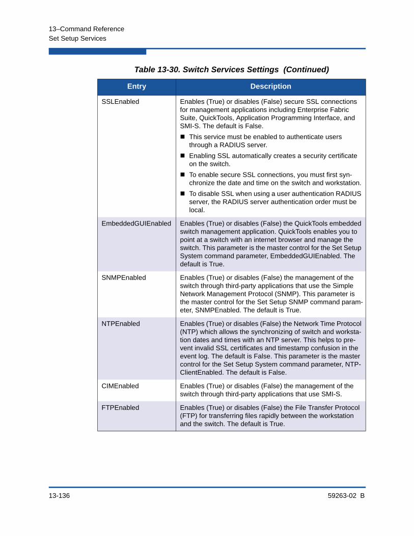
13–Command Reference
Set Setup Services
13-136 59263-02 B
SSLEnabled Enables (True) or disables (False) secure SSL connections for management applications including Enterprise Fabric Suite, QuickTools, Application Programming Interface, and SMI-S. The default is False.
This service must be enabled to authenticate users through a RADIUS server.
Enabling SSL automatically creates a security certificate on the switch.
To enable secure SSL connections, you must first syn-chronize the date and time on the switch and workstation.
To disable SSL when using a user authentication RADIUS server, the RADIUS server authentication order must be local.
EmbeddedGUIEnabled Enables (True) or disables (False) the QuickTools embedded switch management application. QuickTools enables you to point at a switch with an internet browser and manage the switch. This parameter is the master control for the Set Setup System command parameter, EmbeddedGUIEnabled. The default is True.
SNMPEnabled Enables (True) or disables (False) the management of the switch through third-party applications that use the Simple Network Management Protocol (SNMP). This parameter is the master control for the Set Setup SNMP command param-eter, SNMPEnabled. The default is True.
NTPEnabled Enables (True) or disables (False) the Network Time Protocol (NTP) which allows the synchronizing of switch and worksta-tion dates and times with an NTP server. This helps to pre-vent invalid SSL certificates and timestamp confusion in the event log. The default is False. This parameter is the master control for the Set Setup System command parameter, NTP-ClientEnabled. The default is False.
CIMEnabled Enables (True) or disables (False) the management of the switch through third-party applications that use SMI-S.
FTPEnabled Enables (True) or disables (False) the File Transfer Protocol (FTP) for transferring files rapidly between the workstation and the switch. The default is True.
Table 13-30. Switch Services Settings (Continued)
Entry Description

13–Command Reference
Set Setup Services
59263-02 B 13-137
Examples The following is an example of the Set Setup Services command:
SANbox #> admin start
SANbox (admin) #> set setup services
A list of attributes with formatting and current values will follow.
Enter a new value or simply press the ENTER key to accept the current value.
If you wish to terminate this process before reaching the end of the list
press 'q' or 'Q' and the ENTER key to do so.
PLEASE NOTE:
-----------
* Further configuration may be required after enabling a service.
* If services are disabled, the connection to the switch may be lost.
* When enabling SSL, please verify that the date/time settings
on this switch and the workstation from where the SSL connection
will be started match, and then a new certificate may need to be
created to ensure a secure connection to this switch.
TelnetEnabled (True / False) [True ]
SSHEnabled (True / False) [False]
GUIMgmtEnabled (True / False) [True ]
SSLEnabled (True / False) [False]
EmbeddedGUIEnabled (True / False) [True ]
SNMPEnabled (True / False) [True ]
NTPEnabled (True / False) [False]
CIMEnabled (True / False) [False]
FTPEnabled (True / False) [True ]
MgmtServerEnabled (True / False) [True ]
CallHomeEnabled (True / False) [True ]
Do you want to save and activate this services setup? (y/n): [n]
MgmtServerEnabled Enables (True) or disables (False) the management of the switch through third-party applications that use GS-3 Man-agement Server (MS). This parameter is the master control for the Set Config Port command parameter, MSEnable. The default is True.
CallHomeEnabled Enables (True) or disables (False) the Call Home service which controls e-mail notification. The default is True.
Table 13-30. Switch Services Settings (Continued)
Entry Description

13–Command Reference
Set Setup SNMP
13-138 59263-02 B
Set Setup SNMPConfigures SNMP on the switch.
Authority Admin session
Syntax set setup snmpcommontrap [trap_number]
Keywords commonPrompts you in a line-by-line fashion to change SNMP configuration parameters that are common for all traps. For each parameter, enter a new value or press the Enter key to accept the current value. To configure common parameters and trap parameters, omit the Common keyword. Refer to Table 13-32 for a description of the SNMP trap parameters. Table 13-31 describes the common SNMP configuration parameters.
Table 13-31. SNMP Common Configuration Parameters
Parameter Description
SNMPEnabled Enables (True) or disables (False) SNMP on the switch. The default is True.
Contact Specifies the name of the person to be contacted to respond to trap events. The name can be up to 64 characters excluding #, semicolon (;), and comma (,). The default is undefined. This value is also passed to the Call Home service configuration.
Location Specifies the name of the switch location. The name can be up to 64 characters excluding #, semicolon (;), and comma (,). The default is undefined. This value is also passed to the Call Home service configuration.
ReadCommunity Read community password that authorizes an SNMP agent to read information from the switch. This is a write-only field. The value on the switch and the SNMP management server must be the same. The read community password can be up to 32 characters excluding #, semicolon (;), and comma (,). The default is “public”.
WriteCommunity Write community password that authorizes an SNMP agent to write information to the switch. This is a write-only field. The value on the switch and the SNMP management server must be the same. The write community password can be up to 32 characters excluding #, semicolon (;), and comma (,). The default is “private”.

13–Command Reference
Set Setup SNMP
59263-02 B 13-139
trap [trap_number]
Prompts you in a line-by-line fashion to change SNMP trap parameters for the trap number given by [trap_number]. [trap_number] can be 1–5. For each parameter, enter a new value or press the Enter key to accept the current value. To configure common parameters and trap parameters, omit the Trap keyword. Refer to Table 13-31 for a description of the SNMP trap parameters.Table 13-32 describes the trap parameters.
TrapCommunity Trap community password that authorizes an SNMP agent to receive traps. This is a write-only field. The value on the switch and the SNMP management server must be the same. The trap community password can be up to 32 characters excluding #, semicolon (;), and comma (,). The default is “public”.
AuthFailureTrap Enables (True) or disables (False) the generation of traps in response to trap authentication failures. The default is False.
ProxyEnabled Enables (True) or disables (False) SNMP communication with other switches in the fabric. The default is True.
SNMPv3Enabled Enables (True) or disables (False) SNMP version 3. The default is False.
Table 13-32. SNMP Trap Configuration Parameters
Parameter Description
Trap[1–5]Address Workstation IP address (version 4 or 6) or DNS host name to which SNMP traps are sent. The default address for trap 1 is 10.0.0.254. The default address for traps 2–5 is 0.0.0.0. Addresses, other than 0.0.0.0, for all traps must be unique.
Trap[1–5]Port Workstation port to which SNMP traps are sent. Valid worksta-tion port numbers are 1–65535. The default is 162.
Trap[1–5]Severity Severity level to use when monitoring trap events. The default is Warning.
Trap[1–5]Version SNMP version (1 or 2) to use in formatting the trap. The default is 2.
Trap[1–5]Enabled Enables (True) or disables (False) the SNMP trap.
Table 13-31. SNMP Common Configuration Parameters (Continued)
Parameter Description

13–Command Reference
Set Setup SNMP
13-140 59263-02 B
Examples The following is an example of the Set Setup Snmp Common command:
SANbox (admin) #> set setup snmp common
A list of attributes with formatting and current values will follow.
Enter a new value or simply press the ENTER key to accept the current value.
If you wish to terminate this process before reaching the end of the list
press 'q' or 'Q' and the ENTER key to do so.
Current Values:
SnmpEnabled True
Contact <sysContact undefined>
Location <sysLocation undefined>
ReadCommunity public
WriteCommunity private
AuthFailureTrap False
ProxyEnabled True
SNMPv3Enabled False
New Value (press ENTER to not specify value, 'q' to quit):
SnmpEnabled (True / False) :
Contact (string, max=64 chars) :
Location (string, max=64 chars) :
ReadCommunity (string, max=32 chars) :
WriteCommunity (string, max=32 chars) :
AuthFailureTrap (True / False) :
ProxyEnabled (True / False) :
SNMPv3Enabled (True / False) :
Do you want to save and activate this snmp setup? (y/n): [n]

13–Command Reference
Set Setup SNMP
59263-02 B 13-141
The following is an example of the Set Setup Snmp Trap command:
SANbox (admin) #> set setup snmp trap 1
A list of attributes with formatting and current values will follow.
Enter a new value or simply press the ENTER key to accept the current value.
If you wish to terminate this process before reaching the end of the list
press 'q' or 'Q' and the ENTER key to do so.
Current Values:
Trap1Enabled True
Trap1Address 10.20.33.181
Trap1Port 5001
Trap1Severity info
Trap1Version 2
Trap1Community northdakota
New Value (press ENTER to not specify value, 'q' to quit):
Trap1Enabled (True / False) :
Trap1Address (hostname, IPv4, or IPv6 Address) :
Trap1Port (decimal value, 1-65535) :
Trap1Severity (select a severity level)
1=unknown 6=warning
2=emergency 7=notify
3=alert 8=info
4=critical 9=debug
5=error 10=mark :
Trap1Version (1 / 2) :
Trap1Community (string, max=32 chars) :
Do you want to save and activate this snmp setup? (y/n): [n]

13–Command Reference
Set Setup System
13-142 59263-02 B
Set Setup SystemConfigures the network, logging, NTP server, and timer configurations on the switch.
Authority Admin session
Syntax set setup systemdnsipv4ipv6loggingntptimers
Keywords dnsPrompts you in a line-by-line fashion to change DNS host name configuration parameters described in Table 13-33. To configure all system parameters, omit the keyword. For each parameter, enter a new value or press the Enter key to accept the current value.
Table 13-33. DNS Host Name Configuration Parameters
Parameter Description
DNSClientEnabled Enables (True) or disables (False) the DNS client.
DNSLocalHostname Name of local DNS server
DNSServerDiscovery DNS server boot method: 1 – Static, 2 – DHCP, 3 – DHCP version 6. The default is 1 - Static.
DNSServer1Address
DNSServer2Address
DNSServer3Address
IP addresses (version 4 or 6) of up to three DNS serv-ers.
DNSSearchListDiscovery DNS search list discovery method:
Static
DHCP for IP version 4
DHCP for IP version 6
DNSSearchList1
DNSSearchList2
DNSSearchList3
DNSSearchList4
DNSSearchList5
A suffix that is appended to unqualified host names to extend the DNS search. You can specify up to five searchlists (or suffixes).
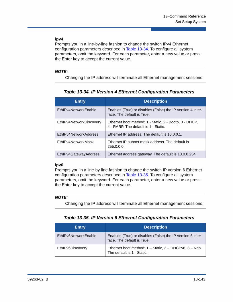
13–Command Reference
Set Setup System
59263-02 B 13-143
ipv4Prompts you in a line-by-line fashion to change the switch IPv4 Ethernet configuration parameters described in Table 13-34. To configure all system parameters, omit the keyword. For each parameter, enter a new value or press the Enter key to accept the current value.
ipv6Prompts you in a line-by-line fashion to change the switch IP version 6 Ethernet configuration parameters described in Table 13-35. To configure all system parameters, omit the keyword. For each parameter, enter a new value or press the Enter key to accept the current value.
NOTE:
Changing the IP address will terminate all Ethernet management sessions.
Table 13-34. IP Version 4 Ethernet Configuration Parameters
Entry Description
EthIPv4NetworkEnable Enables (True) or disables (False) the IP version 4 inter-face. The default is True.
EthIPv4NetworkDiscovery Ethernet boot method: 1 - Static, 2 - Bootp, 3 - DHCP, 4 - RARP. The default is 1 - Static.
EthIPv4NetworkAddress Ethernet IP address. The default is 10.0.0.1.
EthIPv4NetworkMask Ethernet IP subnet mask address. The default is 255.0.0.0.
EthIPv4GatewayAddress Ethernet address gateway. The default is 10.0.0.254
NOTE:
Changing the IP address will terminate all Ethernet management sessions.
Table 13-35. IP Version 6 Ethernet Configuration Parameters
Entry Description
EthIPv6NetworkEnable Enables (True) or disables (False) the IP version 6 inter-face. The default is True.
EthIPv6Discovery Ethernet boot method: 1 – Static, 2 – DHCPv6, 3 – Ndp. The default is 1 - Static.

13–Command Reference
Set Setup System
13-144 59263-02 B
logging
Prompts you in a line-by-line fashion to change the event logging configuration parameters described in Table 13-36. To configure all system parameters, omit the keyword. For each parameter, enter a new value or press the Enter key to accept the current value.
ntp
Prompts you in a line-by-line fashion to change the NTP server configuration parameters described in Table 13-37. To configure all system parameters, omit the keyword. For each parameter, enter a new value or press the Enter key to accept the current value.
EthIPv6NetworkAddress Ethernet IP address
EthIPv6NetworkMask Ethernet IP subnet mask address.
EthIPv6GatewayAddress Ethernet IP address gateway.
Table 13-36. Event Logging Configuration Parameters
Parameter Description
LocalLogEnabled Enables (True) or disables (False) the saving of log infor-mation on the switch. The default is True.
RemoteLogEnabled Enables (True) or disables (False) the recording of the switch event log on a remote host that supports the sys-log protocol. The default is False.
RemoteLogHostAddress The IP address (version 4 or 6) or DNS host name of the host that will receive the switch event log information if remote logging is enabled. The default is 10.0.0.254.
Table 13-37. NTP Server Configuration Parameters
Parameter Description
EthNetworkDiscovery Ethernet boot method: 1 - Static, 2 - Bootp, 3 - DHCP, 4 - RARP. The default is 1 - Static.
EthNetworkAddress Ethernet Internet Protocol (IP) address. The default is 10.0.0.1.
Table 13-35. IP Version 6 Ethernet Configuration Parameters
Entry Description

13–Command Reference
Set Setup System
59263-02 B 13-145
timers
Prompts you in a line-by-line fashion to change the timer configuration parameters described in Table 13-38. To configure all system parameters, omit the keyword. For each parameter, enter a new value or press the Enter key to accept the current value.
NTPClientEnabled Enables (True) or disables (False) the Network Time Pro-tocol (NTP) client on the switch. This client enables the switch to synchronize its time with an NTP server. This feature supports NTP version 4 and is compatible with version 3. An Ethernet connection to the server is required and you must first set an initial time and date on the switch. The synchronized time becomes effective immediately. The default is False.
NTPServerAddress The IP address (version 4 or 6) or DNS host name of the NTP server from which the NTP client acquires the time and date. The default is 10.0.0.254.
Table 13-38. Timer Configuration Parameters
Parameter Description
AdminTimeout Amount of time in minutes the switch waits before termi-nating an idle Admin session. Zero (0) disables the time out threshold. The default is 30, the maximum is 1440.
InactivityTimeout Amount of time in minutes the switch waits before termi-nating an idle Telnet command line interface session. Zero (0) disables the time out threshold. The default is 0, the maximum is 1440.
Table 13-37. NTP Server Configuration Parameters (Continued)
Parameter Description
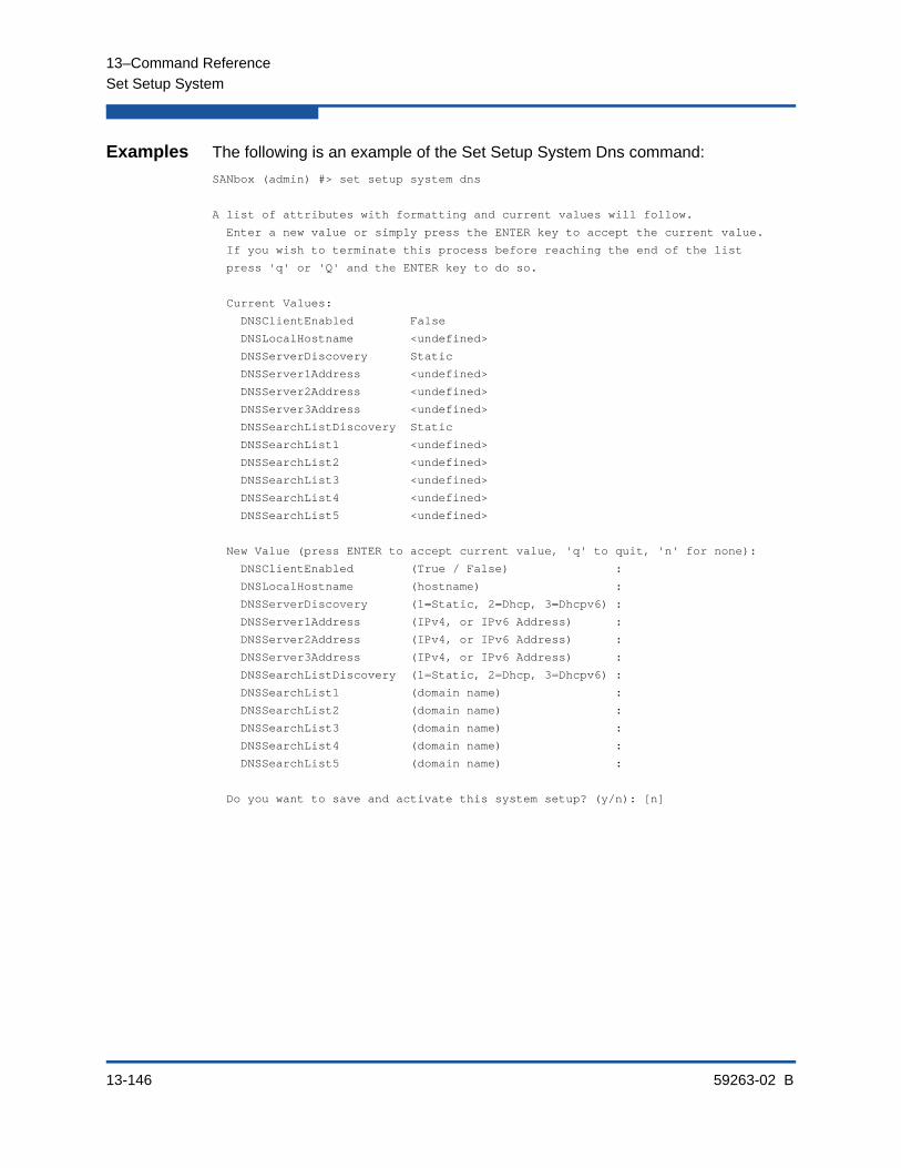
13–Command Reference
Set Setup System
13-146 59263-02 B
Examples The following is an example of the Set Setup System Dns command:
SANbox (admin) #> set setup system dns
A list of attributes with formatting and current values will follow.
Enter a new value or simply press the ENTER key to accept the current value.
If you wish to terminate this process before reaching the end of the list
press 'q' or 'Q' and the ENTER key to do so.
Current Values:
DNSClientEnabled False
DNSLocalHostname <undefined>
DNSServerDiscovery Static
DNSServer1Address <undefined>
DNSServer2Address <undefined>
DNSServer3Address <undefined>
DNSSearchListDiscovery Static
DNSSearchList1 <undefined>
DNSSearchList2 <undefined>
DNSSearchList3 <undefined>
DNSSearchList4 <undefined>
DNSSearchList5 <undefined>
New Value (press ENTER to accept current value, 'q' to quit, 'n' for none):
DNSClientEnabled (True / False) :
DNSLocalHostname (hostname) :
DNSServerDiscovery (1=Static, 2=Dhcp, 3=Dhcpv6) :
DNSServer1Address (IPv4, or IPv6 Address) :
DNSServer2Address (IPv4, or IPv6 Address) :
DNSServer3Address (IPv4, or IPv6 Address) :
DNSSearchListDiscovery (1=Static, 2=Dhcp, 3=Dhcpv6) :
DNSSearchList1 (domain name) :
DNSSearchList2 (domain name) :
DNSSearchList3 (domain name) :
DNSSearchList4 (domain name) :
DNSSearchList5 (domain name) :
Do you want to save and activate this system setup? (y/n): [n]
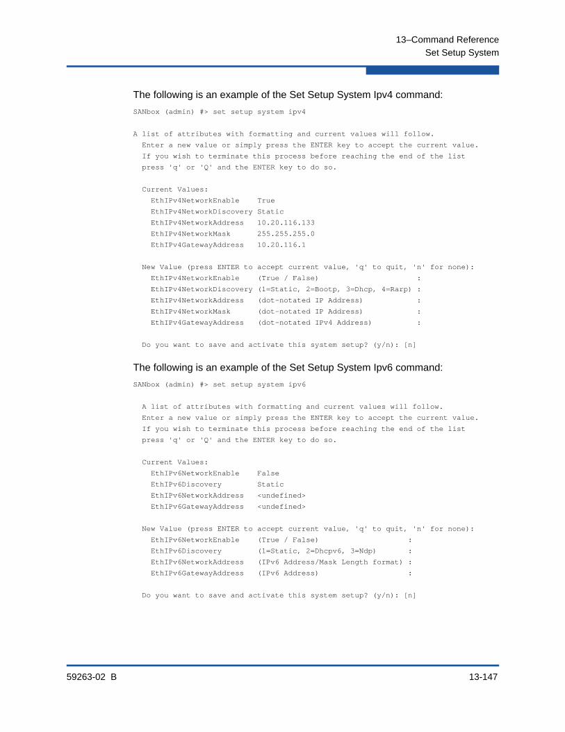
13–Command Reference
Set Setup System
59263-02 B 13-147
The following is an example of the Set Setup System Ipv4 command:
SANbox (admin) #> set setup system ipv4
A list of attributes with formatting and current values will follow.
Enter a new value or simply press the ENTER key to accept the current value.
If you wish to terminate this process before reaching the end of the list
press 'q' or 'Q' and the ENTER key to do so.
Current Values:
EthIPv4NetworkEnable True
EthIPv4NetworkDiscovery Static
EthIPv4NetworkAddress 10.20.116.133
EthIPv4NetworkMask 255.255.255.0
EthIPv4GatewayAddress 10.20.116.1
New Value (press ENTER to accept current value, 'q' to quit, 'n' for none):
EthIPv4NetworkEnable (True / False) :
EthIPv4NetworkDiscovery (1=Static, 2=Bootp, 3=Dhcp, 4=Rarp) :
EthIPv4NetworkAddress (dot-notated IP Address) :
EthIPv4NetworkMask (dot-notated IP Address) :
EthIPv4GatewayAddress (dot-notated IPv4 Address) :
Do you want to save and activate this system setup? (y/n): [n]
The following is an example of the Set Setup System Ipv6 command:
SANbox (admin) #> set setup system ipv6
A list of attributes with formatting and current values will follow.
Enter a new value or simply press the ENTER key to accept the current value.
If you wish to terminate this process before reaching the end of the list
press 'q' or 'Q' and the ENTER key to do so.
Current Values:
EthIPv6NetworkEnable False
EthIPv6Discovery Static
EthIPv6NetworkAddress <undefined>
EthIPv6GatewayAddress <undefined>
New Value (press ENTER to accept current value, 'q' to quit, 'n' for none):
EthIPv6NetworkEnable (True / False) :
EthIPv6Discovery (1=Static, 2=Dhcpv6, 3=Ndp) :
EthIPv6NetworkAddress (IPv6 Address/Mask Length format) :
EthIPv6GatewayAddress (IPv6 Address) :
Do you want to save and activate this system setup? (y/n): [n]
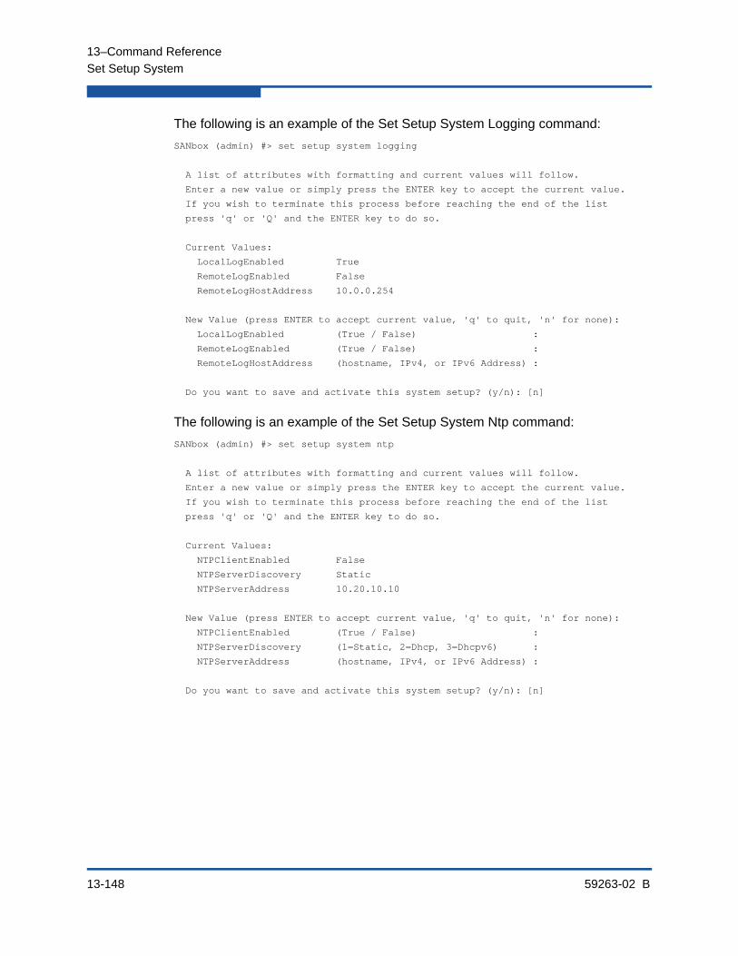
13–Command Reference
Set Setup System
13-148 59263-02 B
The following is an example of the Set Setup System Logging command:
SANbox (admin) #> set setup system logging
A list of attributes with formatting and current values will follow.
Enter a new value or simply press the ENTER key to accept the current value.
If you wish to terminate this process before reaching the end of the list
press 'q' or 'Q' and the ENTER key to do so.
Current Values:
LocalLogEnabled True
RemoteLogEnabled False
RemoteLogHostAddress 10.0.0.254
New Value (press ENTER to accept current value, 'q' to quit, 'n' for none):
LocalLogEnabled (True / False) :
RemoteLogEnabled (True / False) :
RemoteLogHostAddress (hostname, IPv4, or IPv6 Address) :
Do you want to save and activate this system setup? (y/n): [n]
The following is an example of the Set Setup System Ntp command:
SANbox (admin) #> set setup system ntp
A list of attributes with formatting and current values will follow.
Enter a new value or simply press the ENTER key to accept the current value.
If you wish to terminate this process before reaching the end of the list
press 'q' or 'Q' and the ENTER key to do so.
Current Values:
NTPClientEnabled False
NTPServerDiscovery Static
NTPServerAddress 10.20.10.10
New Value (press ENTER to accept current value, 'q' to quit, 'n' for none):
NTPClientEnabled (True / False) :
NTPServerDiscovery (1=Static, 2=Dhcp, 3=Dhcpv6) :
NTPServerAddress (hostname, IPv4, or IPv6 Address) :
Do you want to save and activate this system setup? (y/n): [n]

13–Command Reference
Set Setup System
59263-02 B 13-149
The following is an example of the Set Setup System Timers command:
SANbox (admin) #> set setup system timers
A list of attributes with formatting and current values will follow.
Enter a new value or simply press the ENTER key to accept the current value.
If you wish to terminate this process before reaching the end of the list
press 'q' or 'Q' and the ENTER key to do so.
Current Values:
AdminTimeout 30
InactivityTimeout 0
New Value (press ENTER to accept current value, 'q' to quit):
AdminTimeout (dec value 0-1440 minutes, 0=never) :
InactivityTimeout (dec value 0-1440 minutes, 0=never) :
Do you want to save and activate this system setup? (y/n): [n]

13–Command Reference
Set Switch State
13-150 59263-02 B
Set Switch StateChanges the administrative state for all ports on the switch. The previous Set Config Switch settings are restored after a switch reset or a reactivation of a switch configuration.
Authority Admin session
Syntax set switch state [state]
Keywords [state]
[state] can be one of the following:
online
Activates and prepares the ports to send data. This is the default.
offline
Prevents the ports from receiving signal and accepting a device login.
diagnostics
Prepares the ports for testing and prevents each port from accepting a device login. When you leave the diagnostics state, the switch automatically resets.
Notes Enterprise Fabric Suite and QuickTools will override any temporary administrative state changes that have been made using the Set Switch command. Therefore, to avoid unexpected results, do not manage switch administrative states with Enterprise Fabric Suite or QuickTools and the CLI at the same time.
Examples The following is an example of the Set Switch command:
SANbox #>admin start
SANbox (admin) #>set switch state offline

13–Command Reference
Set Timezone
59263-02 B 13-151
Set TimezoneSpecifies the time zone for the switch and the workstation. The default is Universal Time (UTC) also known as Greenwich Mean Time (GMT). This keyword prompts you to choose a region, then a subregion to specify the time zone. Changing the time zone converts the currently displayed time to the time in the new time zone.
Authority Admin session
Syntax set timezone
Examples The following is an example of the Set Timezone command:
SANbox #> admin start
SANbox (admin) #> set timezone
Africa America
Antarctica Asia
Atlantic Australia
Europe Indian
Pacific UTC
Press ENTER for more options or 'q' to make a selection.
America/Grenada America/Guadeloupe
America/Guatemala America/Guayaquil
America/Guyana America/Halifax
America/Havana America/Hermosillo
America/Indiana America/Indianapolis
.
.
.
America/Monterrey America/Montevideo
America/Montreal America/Montserrat
America/Nassau America/New_York
America/Nipigon America/Nome
America/Noronha America/North_Dakota
America/Panama America/Pangnirtung
Press ENTER for more options or 'q' to make a selection.
q
Enter selection (or 'q' to quit): america/north_dakota
America/North_Dakota/Center
Enter selection (or 'q' to quit): america/north_dakota/center

13–Command Reference
Show About
13-152 59263-02 B
Show AboutDisplays an introductory set of information about operational attributes of the switch. This command is equivalent to the Show Version command.
Authority None
Syntax show about
Notes Table 13-39 describes the entries in the Show About command display.
Table 13-39. Show About Display Entries
Entry Description
SystemDescription Switch system description
HostName DNS host name
EthIPv4NetworkAddress IP address, version 4
EthIPv6NetworkAddress IP address, version 6
MacAddress Switch MAC address
WorldWideName Switch worldwide name
ChassisSerialNumber Switch serial number
SymbolicName Switch symbolic name
ActiveSWVersion Firmware version
ActiveTimestamp Date and time that the firmware was activated
POSTStatus Results of the Power-on Self Test
LicensedPorts Number of licensed ports
SwitchMode Full Fabric indicates that the switch operates with the standard Fibre Channel port types: G, GL, F, FL, E, TR.

13–Command Reference
Show About
59263-02 B 13-153
Examples The following is an example of the Show About command:
SANbox #> show about
*****************************************************
* *
* Command Line Interface SHell (CLISH) *
* *
*****************************************************
SystemDescription QLogic 5800V FC Switch
HostName <undefined>
EthIPv4NetworkAddress 10.20.11.192
EthIPv6NetworkAddress ::
MACAddress 00:c0:dd:00:71:ee
WorldWideName 10:00:00:c0:dd:00:71:ed
ChassisSerialNumber FAM033100024
SymbolicName SANbox
ActiveSWVersion V8.0.x.x.xx.xx
ActiveTimestamp day month date time year
POSTStatus Passed
LicensedPorts 24
SwitchMode Full Fabric
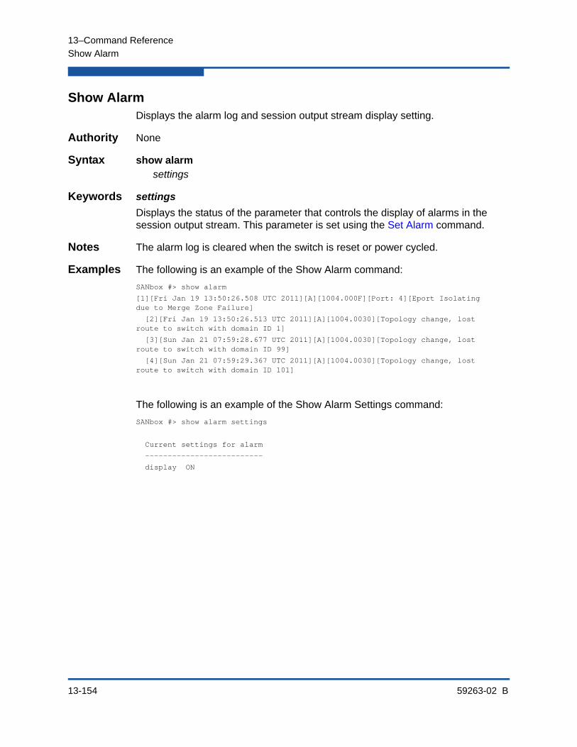
13–Command Reference
Show Alarm
13-154 59263-02 B
Show AlarmDisplays the alarm log and session output stream display setting.
Authority None
Syntax show alarmsettings
Keywords settings
Displays the status of the parameter that controls the display of alarms in the session output stream. This parameter is set using the Set Alarm command.
Notes The alarm log is cleared when the switch is reset or power cycled.
Examples The following is an example of the Show Alarm command:
SANbox #> show alarm
[1][Fri Jan 19 13:50:26.508 UTC 2011][A][1004.000F][Port: 4][Eport Isolating due to Merge Zone Failure]
[2][Fri Jan 19 13:50:26.513 UTC 2011][A][1004.0030][Topology change, lost route to switch with domain ID 1]
[3][Sun Jan 21 07:59:28.677 UTC 2011][A][1004.0030][Topology change, lost route to switch with domain ID 99]
[4][Sun Jan 21 07:59:29.367 UTC 2011][A][1004.0030][Topology change, lost route to switch with domain ID 101]
The following is an example of the Show Alarm Settings command:
SANbox #> show alarm settings
Current settings for alarm
--------------------------
display ON

13–Command Reference
Show Broadcast
59263-02 B 13-155
Show BroadcastDisplays the broadcast tree information and all ports that are currently transmitting and receiving broadcast frames.
Authority None
Syntax show broadcast
Examples The following is an example of the Show Broadcast command:
SANbox #> show broadcast
Group Member Ports ISL Ports
----- ------------ ---------
0 3 16
15
16
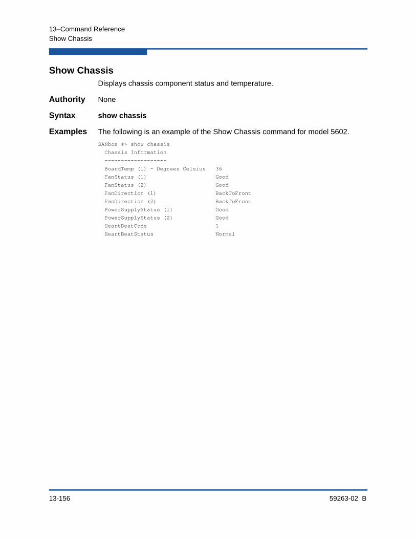
13–Command Reference
Show Chassis
13-156 59263-02 B
Show ChassisDisplays chassis component status and temperature.
Authority None
Syntax show chassis
Examples The following is an example of the Show Chassis command for model 5602.
SANbox #> show chassis
Chassis Information
-------------------
BoardTemp (1) - Degrees Celsius 36
FanStatus (1) Good
FanStatus (2) Good
FanDirection (1) BackToFront
FanDirection (2) BackToFront
PowerSupplyStatus (1) Good
PowerSupplyStatus (2) Good
HeartBeatCode 1
HeartBeatStatus Normal
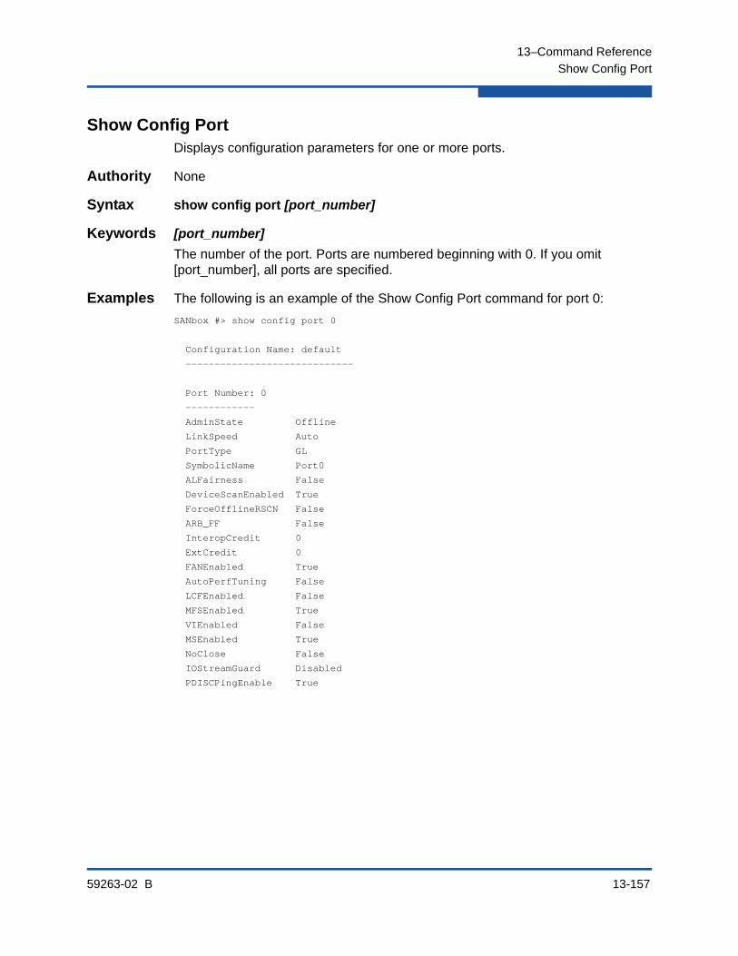
13–Command Reference
Show Config Port
59263-02 B 13-157
Show Config PortDisplays configuration parameters for one or more ports.
Authority None
Syntax show config port [port_number]
Keywords [port_number]
The number of the port. Ports are numbered beginning with 0. If you omit [port_number], all ports are specified.
Examples The following is an example of the Show Config Port command for port 0:
SANbox #> show config port 0
Configuration Name: default
-----------------------------
Port Number: 0
------------
AdminState Offline
LinkSpeed Auto
PortType GL
SymbolicName Port0
ALFairness False
DeviceScanEnabled True
ForceOfflineRSCN False
ARB_FF False
InteropCredit 0
ExtCredit 0
FANEnabled True
AutoPerfTuning False
LCFEnabled False
MFSEnabled True
VIEnabled False
MSEnabled True
NoClose False
IOStreamGuard Disabled
PDISCPingEnable True
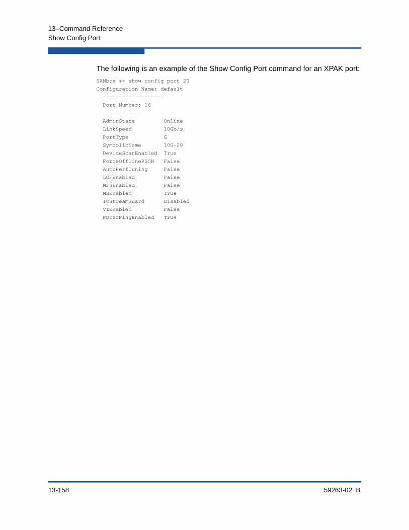
13–Command Reference
Show Config Port
13-158 59263-02 B
The following is an example of the Show Config Port command for an XPAK port:
SANbox #> show config port 20
Configuration Name: default
-------------------
Port Number: 16
------------
AdminState Online
LinkSpeed 10Gb/s
PortType G
SymbolicName 10G-20
DeviceScanEnabled True
ForceOfflineRSCN False
AutoPerfTuning False
LCFEnabled False
MFSEnabled False
MSEnabled True
IOStreamGuard Disabled
VIEnabled False
PDISCPingEnabled True

13–Command Reference
Show Config Security
59263-02 B 13-159
Show Config SecurityDisplays the security database configuration parameters.
Authority None
Syntax show config security
Examples The following is an example of the Show Config Security command:
SANbox #> show config security
Configuration Name: default
-------------------
Switch Security Configuration Information
-----------------------------------------
FabricBindingEnabled False
AutoSave True
Port Binding Status WWN
---- -------------- ---
0 True 10:20:30:40:50:60:70:80
1 True 10:20:30:40:50:60:70:80
2 False No port binding entries found.
3 True 10:20:30:40:50:60:70:80
4 True 10:20:30:40:50:60:70:80
5 False No port binding entries found.
6 True 10:20:30:40:50:60:70:81
7 False No port binding entries found.
8 True 10:20:30:40:50:60:70:80
9 False No port binding entries found.
10 False No port binding entries found.
11 False No port binding entries found.
12 False No port binding entries found.
13 False No port binding entries found.
14 False No port binding entries found.
15 False No port binding entries found.
16 False No port binding entries found.
17 False No port binding entries found.
18 False No port binding entries found.
19 False No port binding entries found.
20 False No port binding entries found.
21 False No port binding entries found.
22 False No port binding entries found.
23 False No port binding entries found.
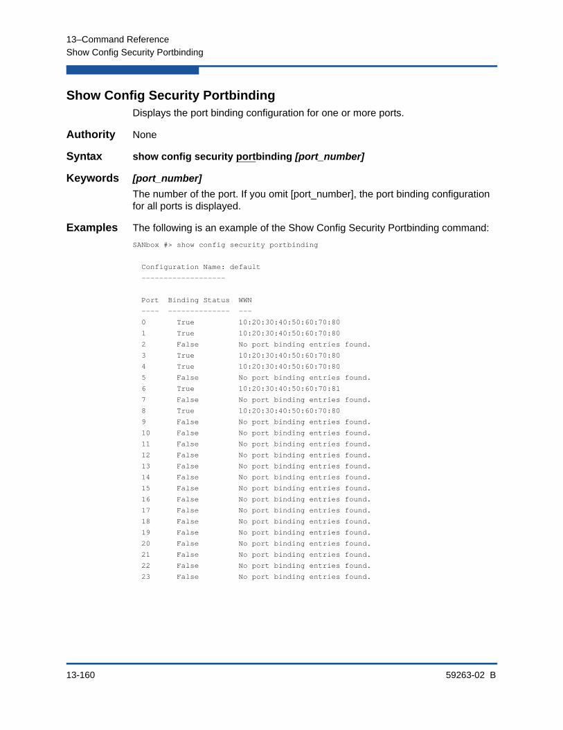
13–Command Reference
Show Config Security Portbinding
13-160 59263-02 B
Show Config Security PortbindingDisplays the port binding configuration for one or more ports.
Authority None
Syntax show config security portbinding [port_number]
Keywords [port_number]
The number of the port. If you omit [port_number], the port binding configuration for all ports is displayed.
Examples The following is an example of the Show Config Security Portbinding command:
SANbox #> show config security portbinding
Configuration Name: default
-------------------
Port Binding Status WWN
---- -------------- ---
0 True 10:20:30:40:50:60:70:80
1 True 10:20:30:40:50:60:70:80
2 False No port binding entries found.
3 True 10:20:30:40:50:60:70:80
4 True 10:20:30:40:50:60:70:80
5 False No port binding entries found.
6 True 10:20:30:40:50:60:70:81
7 False No port binding entries found.
8 True 10:20:30:40:50:60:70:80
9 False No port binding entries found.
10 False No port binding entries found.
11 False No port binding entries found.
12 False No port binding entries found.
13 False No port binding entries found.
14 False No port binding entries found.
15 False No port binding entries found.
16 False No port binding entries found.
17 False No port binding entries found.
18 False No port binding entries found.
19 False No port binding entries found.
20 False No port binding entries found.
21 False No port binding entries found.
22 False No port binding entries found.
23 False No port binding entries found.

13–Command Reference
Show Config Switch
59263-02 B 13-161
Show Config SwitchDisplays the switch configuration parameters.
Authority None
Syntax show config switch
Examples The following is an example of the Show Config Switch command:
SANbox #> show config switch
Configuration Name: default
-------------------
Switch Configuration Information
--------------------------------
AdminState Online
BroadcastEnabled False
InbandEnabled True
FDMIEnabled False
FDMIEntries 10
DefaultDomainID 19 (0x13)
DomainIDLock True
SymbolicName sw108
R_A_TOV 10000
E_D_TOV 2000
PrincipalPriority 254
ConfigDescription Default Config
ConfigLastSavedBy admin@OB-session5
ConfigLastSavedOn day month date time year
InteropMode Standard

13–Command Reference
Show Config Threshold
13-162 59263-02 B
Show Config ThresholdDisplays alarm threshold parameters for the switch.
Authority None
Syntax show config threshold
Examples The following is an example of the Show Config Threshold command:
SANbox #> show config threshold
Configuration Name: default
------------
Threshold Configuration Information
-----------------------------------
ThresholdMonitoringEnabled False
CRCErrorsMonitoringEnabled True
RisingTrigger 25
FallingTrigger 1
SampleWindow 10
DecodeErrorsMonitoringEnabled True
RisingTrigger 25
FallingTrigger 0
SampleWindow 10
ISLMonitoringEnabled True
RisingTrigger 2
FallingTrigger 0
SampleWindow 10
LoginMonitoringEnabled True
RisingTrigger 5
FallingTrigger 1
SampleWindow 10
LogoutMonitoringEnabled True
RisingTrigger 5
FallingTrigger 1
SampleWindow 10
LOSMonitoringEnabled True
RisingTrigger 100
FallingTrigger 5
SampleWindow 10
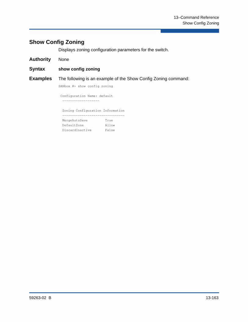
13–Command Reference
Show Config Zoning
59263-02 B 13-163
Show Config ZoningDisplays zoning configuration parameters for the switch.
Authority None
Syntax show config zoning
Examples The following is an example of the Show Config Zoning command:
SANbox #> show config zoning
Configuration Name: default
-------------------
Zoning Configuration Information
--------------------------------
MergeAutoSave True
DefaultZone Allow
DiscardInactive False
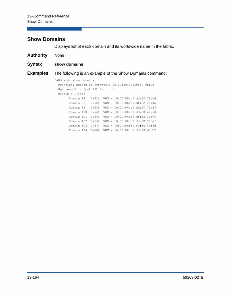
13–Command Reference
Show Domains
13-164 59263-02 B
Show DomainsDisplays list of each domain and its worldwide name in the fabric.
Authority None
Syntax show domains
Examples The following is an example of the Show Domains command:
SANbox #> show domains
Principal switch is (remote): 10:00:00:60:69:50:0b:6c
Upstream Principal ISL is : 1
Domain ID List:
Domain 97 (0x61) WWN = 10:00:00:c0:dd:00:71:ed
Domain 98 (0x62) WWN = 10:00:00:60:df:22:2e:0c
Domain 99 (0x63) WWN = 10:00:00:c0:dd:00:72:45
Domain 100 (0x64) WWN = 10:00:00:c0:dd:00:ba:68
Domain 101 (0x65) WWN = 10:00:00:60:df:22:2e:06
Domain 102 (0x66) WWN = 10:00:00:c0:dd:00:90:ef
Domain 103 (0x67) WWN = 10:00:00:60:69:50:0b:6c
Domain 104 (0x68) WWN = 10:00:00:c0:dd:00:b8:b7
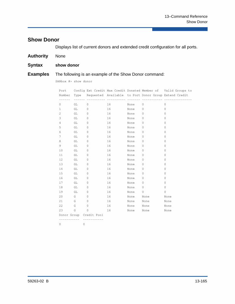
13–Command Reference
Show Donor
59263-02 B 13-165
Show DonorDisplays list of current donors and extended credit configuration for all ports.
Authority None
Syntax show donor
Examples The following is an example of the Show Donor command:
SANbox #> show donor
Port Config Ext Credit Max Credit Donated Member of Valid Groups to
Number Type Requested Available to Port Donor Group Extend Credit
------ ------ ---------- ---------- ------- ----------- ---------------
0 GL 0 16 None 0 0
1 GL 0 16 None 0 0
2 GL 0 16 None 0 0
3 GL 0 16 None 0 0
4 GL 0 16 None 0 0
5 GL 0 16 None 0 0
6 GL 0 16 None 0 0
7 GL 0 16 None 0 0
8 GL 0 16 None 0 0
9 GL 0 16 None 0 0
10 GL 0 16 None 0 0
11 GL 0 16 None 0 0
12 GL 0 16 None 0 0
13 GL 0 16 None 0 0
14 GL 0 16 None 0 0
15 GL 0 16 None 0 0
16 GL 0 16 None 0 0
17 GL 0 16 None 0 0
18 GL 0 16 None 0 0
19 GL 0 16 None 0 0
20 G 0 16 None None None
21 G 0 16 None None None
22 G 0 16 None None None
23 G 0 16 None None None
Donor Group Credit Pool
----------- -----------
0 0

13–Command Reference
Show Env
13-166 59263-02 B
Show EnvDisplays temperature and voltage information.
Authority None
Syntax show env
Examples The following is an example of the Show Env command:
SANbox #> show env
Temperature(C) Sensors:
Sensor Description Status Current High Warn High Alarm
------ ----------- ------ ------- --------- ----------
0 BOARD Normal 24 65 70
1 DS1780 Normal 28 n/a n/a
2 MAX1617 Normal 31 65 70
3 ASIC Normal 49 95 100
Voltage Sensors:
Sensor Description Status Current Low Alarm High Alarm
------ ----------- ------ ------- --------- ----------
0 2.5V Good 2.50 2.20 2.80
1 1.25V Good 1.24 1.00 1.50
2 3.3V Good 3.32 3.02 3.58
3 12V Good 12.00 10.00 13.31
4 1.2V Good 1.26 1.04 1.38
5 1.5V Good 1.50 1.31 1.68
6 1.8V_ANALOG Good 1.78 1.58 2.02
7 1.8V Good 1.79 1.60 1.99
8 2.5V_ANALOG Good 2.40 2.08 2.84

13–Command Reference
Show Fabric
59263-02 B 13-167
Show FabricDisplays list of each domain, symbolic name, worldwide name, node IP address, and port IP address in the fabric.
Authority None
Syntax show fabric brief
Keywords brief
Displays a table of switches in the fabric including domain ID, WWN, and symbolic name. If you omit the Brief keyword, the command displays information for the local switch only.
Examples The following is an example of the Show Fabric command:
SANbox #> show fabric
Domain *133(0x85)
WWN 10:00:00:c0:dd:0d:53:91
SymbolicName SANbox
HostName <undefined>
EthIPv4Address 10.20.116.133
EthIPv6Address <undefined>
* indicates principal switch
The following is an example of the Show Fabric Brief command:
SANbox #> show fabric brief
Domain WWN SymbolicName
------ --- ------------
*16 (0x10) 10:00:00:c0:dd:00:77:81 swsb1.11
17 (0x11) 10:00:00:c0:dd:00:6a:2d sw12
18 (0x12) 10:00:00:c0:dd:00:c3:04 sw.160
19 (0x13) 10:00:00:c0:dd:00:bc:56 Sb2.108
* indicates principal switch

13–Command Reference
Show FDMI
13-168 59263-02 B
Show FDMIDisplays detailed information about the device host bus adapter.
Authority None
Syntax show fdmi [port_wwn]
Keywords [port_wwn]
The device worldwide port name for which to display information. If you omit [port_wwn], the command displays a summary of host bus adapter information for all attached devices in the fabric. Illegal characters in the display appear as question marks (?).
Examples The following is an example of the Show FDMI command:
SANbox #> show fdmi
HBA ID PortID Manufacturer Model Ports
-------- ------ --------------- ------- -----
21:01:00:e0:8b:27:aa:bc 610000 QLogic Corporation QLA2342 2
21:00:00:00:ca:25:9b:96 180100 QLogic Corporation QL2330 2
The following is an example of the Show FDMI WWN command:
SANbox #> show fdmi 21:00:00:e0:8b:09:3b:17
FDMI Information
----------------
Manufacturer QLogic Corporation
SerialNumber [04202
Model QLA2342
ModelDescription QLogic QLA2342 PCI Fibre Channel Adapter
PortID 610000
NodeWWN 20:00:00:e0:8b:07:aa:bc
HardwareVersion FC5010409-10
DriverVersion 8.2.3.10 Beta 2 (W2K VI)
OptionRomVersion 1.21
FirmwareVersion 03.02.13.
OperatingSystem SunOS 5.8
MaximumCTPayload 2040
NumberOfPorts 1
Port 21:01:00:e0:8b:27:aa:bc
SupportedFC4Types FCP
SupportedSpeed 2Gb/s
CurrentSpeed 2Gb/s
MaximumFrameSize 2048
OSDeviceName
HostName
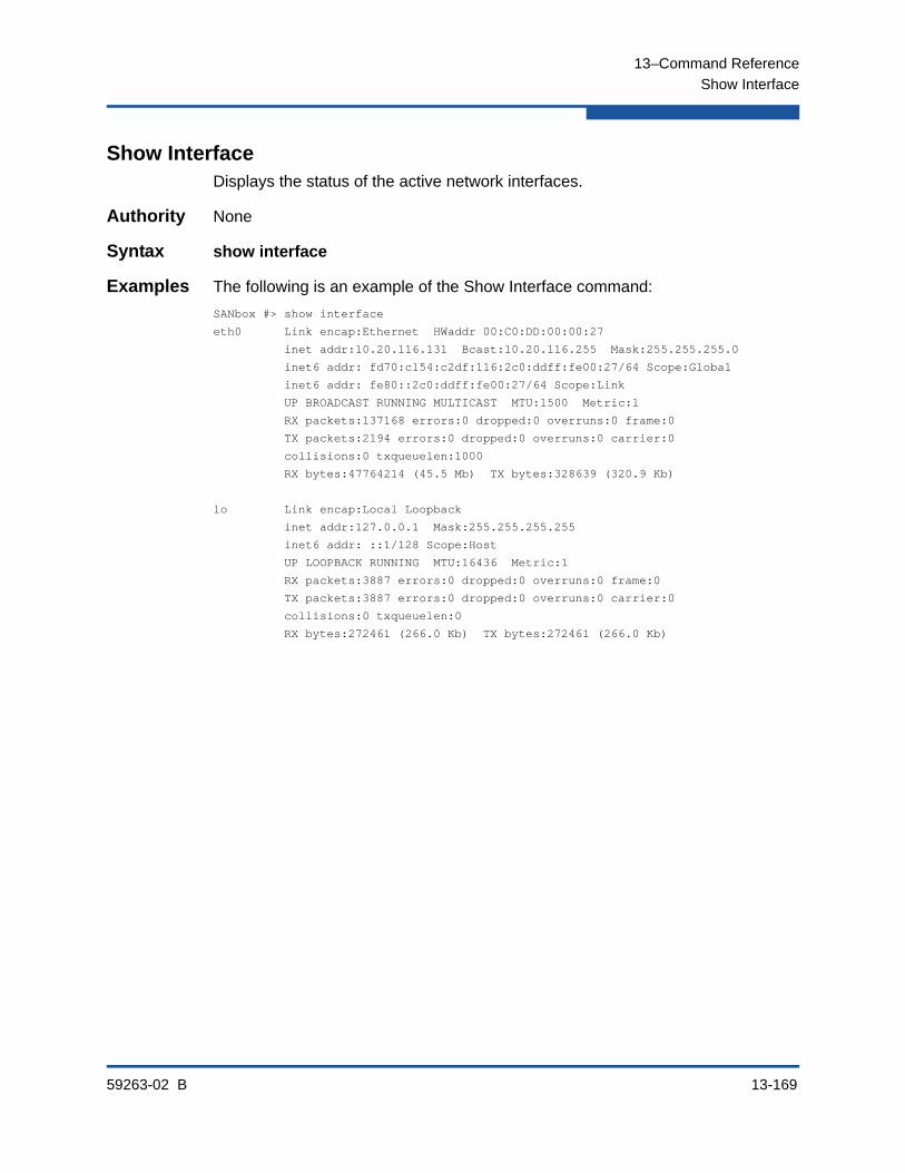
13–Command Reference
Show Interface
59263-02 B 13-169
Show InterfaceDisplays the status of the active network interfaces.
Authority None
Syntax show interface
Examples The following is an example of the Show Interface command:
SANbox #> show interface
eth0 Link encap:Ethernet HWaddr 00:C0:DD:00:00:27
inet addr:10.20.116.131 Bcast:10.20.116.255 Mask:255.255.255.0
inet6 addr: fd70:c154:c2df:116:2c0:ddff:fe00:27/64 Scope:Global
inet6 addr: fe80::2c0:ddff:fe00:27/64 Scope:Link
UP BROADCAST RUNNING MULTICAST MTU:1500 Metric:1
RX packets:137168 errors:0 dropped:0 overruns:0 frame:0
TX packets:2194 errors:0 dropped:0 overruns:0 carrier:0
collisions:0 txqueuelen:1000
RX bytes:47764214 (45.5 Mb) TX bytes:328639 (320.9 Kb)
lo Link encap:Local Loopback
inet addr:127.0.0.1 Mask:255.255.255.255
inet6 addr: ::1/128 Scope:Host
UP LOOPBACK RUNNING MTU:16436 Metric:1
RX packets:3887 errors:0 dropped:0 overruns:0 frame:0
TX packets:3887 errors:0 dropped:0 overruns:0 carrier:0
collisions:0 txqueuelen:0
RX bytes:272461 (266.0 Kb) TX bytes:272461 (266.0 Kb)

13–Command Reference
Show Log
13-170 59263-02 B
Show LogDisplays the contents of the log or the parameters used to create and display entries in the log. The log contains a maximum of 1200 entries. When the log reaches its entry capacity, subsequent entries overwrite the existing entries, beginning with the oldest.
Authority None
Syntax show log[number_of_events]componentdisplay [filter]leveloptionsportsettings
Keywords [number_of_events]
Specifies the number of the most recent events to display from the event log. [number_of_events] must be a positive integer.
component
Displays the components currently being monitored for events. Table 13-40 describes the log monitoring components.
Table 13-40. Log Monitoring Components
Component Description
Chassis Chassis hardware components such as fans and power supplies
CLI Command line interface events
Eport E_Port events
Mgmtserver Management server events
Nameserver Name server events
Other Miscellaneous events
Port Port events
QFS QLogic Fabric Service events. QFS governs Call Home e-mail notification.
SNMP SNMP events
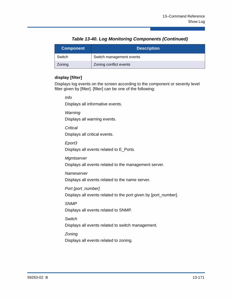
13–Command Reference
Show Log
59263-02 B 13-171
display [filter]
Displays log events on the screen according to the component or severity level filter given by [filter]. [filter] can be one of the following:
Info
Displays all informative events.
Warning
Displays all warning events.
Critical
Displays all critical events.
Eport3
Displays all events related to E_Ports.
Mgmtserver
Displays all events related to the management server.
Nameserver
Displays all events related to the name server.
Port [port_number]
Displays all events related to the port given by [port_number].
SNMP
Displays all events related to SNMP.
Switch
Displays all events related to switch management.
Zoning
Displays all events related to zoning.
Switch Switch management events
Zoning Zoning conflict events
Table 13-40. Log Monitoring Components (Continued)
Component Description
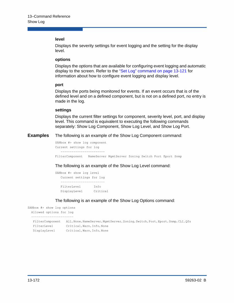
13–Command Reference
Show Log
13-172 59263-02 B
level
Displays the severity settings for event logging and the setting for the display level.
options
Displays the options that are available for configuring event logging and automatic display to the screen. Refer to the “Set Log” command on page 13-121 for information about how to configure event logging and display level.
port
Displays the ports being monitored for events. If an event occurs that is of the defined level and on a defined component, but is not on a defined port, no entry is made in the log.
settings
Displays the current filter settings for component, severity level, port, and display level. This command is equivalent to executing the following commands separately: Show Log Component, Show Log Level, and Show Log Port.
Examples The following is an example of the Show Log Component command:
SANbox #> show log component
Current settings for log
------------------------
FilterComponent NameServer MgmtServer Zoning Switch Port Eport Snmp
The following is an example of the Show Log Level command:
SANbox #> show log level
Current settings for log
------------------------
FilterLevel Info
DisplayLevel Critical
The following is an example of the Show Log Options command:
SANbox #> show log options
Allowed options for log
-----------------------
FilterComponent All,None,NameServer,MgmtServer,Zoning,Switch,Port,Eport,Snmp,CLI,Qfs
FilterLevel Critical,Warn,Info,None
DisplayLevel Critical,Warn,Info,None
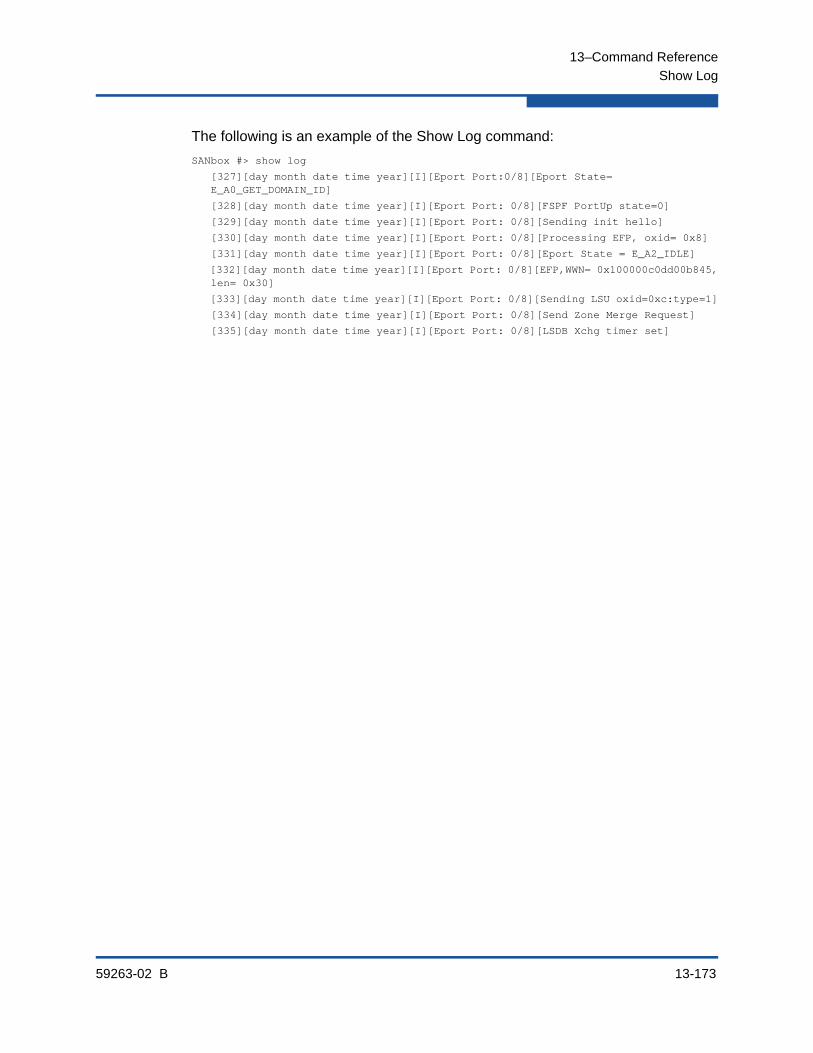
13–Command Reference
Show Log
59263-02 B 13-173
The following is an example of the Show Log command:
SANbox #> show log
[327][day month date time year][I][Eport Port:0/8][Eport State= E_A0_GET_DOMAIN_ID]
[328][day month date time year][I][Eport Port: 0/8][FSPF PortUp state=0]
[329][day month date time year][I][Eport Port: 0/8][Sending init hello]
[330][day month date time year][I][Eport Port: 0/8][Processing EFP, oxid= 0x8]
[331][day month date time year][I][Eport Port: 0/8][Eport State = E_A2_IDLE]
[332][day month date time year][I][Eport Port: 0/8][EFP,WWN= 0x100000c0dd00b845, len= 0x30]
[333][day month date time year][I][Eport Port: 0/8][Sending LSU oxid=0xc:type=1]
[334][day month date time year][I][Eport Port: 0/8][Send Zone Merge Request]
[335][day month date time year][I][Eport Port: 0/8][LSDB Xchg timer set]

13–Command Reference
Show LSDB
13-174 59263-02 B
Show LSDBDisplays Link State database information,
Authority None
Syntax show lsdb
Examples The following is an example of the Show LSDB command:
SANbox #> show lsdb
Link State Database Information
-------------------------------
LsID 34: Age=1176, Incarnation=0x800000e5
NeighborDomain=36, LocalPort=6, RemotePort=7, Cost=500
NeighborDomain=35, LocalPort=16, RemotePort=16, Cost=100
NeighborDomain=35, LocalPort=18, RemotePort=19, Cost=100
NeighborDomain=35, LocalPort=7, RemotePort=7, Cost=500
NeighborDomain=35, LocalPort=5, RemotePort=4, Cost=500
Local Domain
LsID 35: Age=1166, Incarnation=0x800000cc
NeighborDomain=34, LocalPort=16, RemotePort=16, Cost=100
NeighborDomain=34, LocalPort=19, RemotePort=18, Cost=100
NeighborDomain=36, LocalPort=5, RemotePort=4, Cost=250
NeighborDomain=34, LocalPort=7, RemotePort=7, Cost=500
NeighborDomain=34, LocalPort=4, RemotePort=5, Cost=500
Route: OutPort=18, Hops=1, Cost=100
LsID 36: Age=1162, Incarnation=0x80000046
NeighborDomain=34, LocalPort=7, RemotePort=6, Cost=500
NeighborDomain=35, LocalPort=4, RemotePort=5, Cost=250
Route: OutPort=16, Hops=2, Cost=350

13–Command Reference
Show Media
59263-02 B 13-175
Show MediaDisplays transceiver operational and diagnostic information for one or more ports.
Authority None
Syntax show media[port_list]allinstalled
Keywords [port_list]
The port or ports for which to display transceiver information. [port_list] can be a set of port numbers and ranges delimited by spaces. For example, [0 2 10-15] specifies ports 0, 2, 10, 11, 12, 13, 14, and 15.
all
Displays transceiver information for all ports.
installed
Displays transceiver information for all ports that have transceivers installed.
Notes Table 13-41 describes the transceiver information in the Show Media display.
Table 13-41. Transceiver Information
Information Type Description
MediaType Media physical variant. The variant indicates speed, media, transmitter, and distance. The media designator may be M5 (multimode 50 micron), M6 (multimode 62.5 micron), or MX. MX indicates that the media supports both multimode 50 and 62.5 micron.
MediaType may also be on of the following:
NotInstalled–transceiver is not installed.
Unknown–transceiver does not have a serial ID.
NotApplicable–transceiver is not needed.
MediaVendor Vendor name
MediaPartNumber Vendor media part number
MediaRevision Vender media revision level
MediaSerialNumber Vendor media serial number
MediaSpeeds Transmission speed capabilities

13–Command Reference
Show Media
13-176 59263-02 B
Examples The following is an example of the Show Media command for port 4:
SANbox #> show media 4
Port Number: 4
-------------
MediaType 400-M5-SN-I
MediaVendor FINISAR CORP.
MediaPartNumber FTRJ8524P2BNL
MediaRevision A
MediaSerialNumber P6G22RL
MediaSpeeds 1Gb/s, 2Gb/s, 4Gb/s
Temp Voltage Tx Bias Tx Pwr Rx Pwr
(C) (V) (mA) (mW) (mW)
----------- ----------- ------------ ----------- -----------
Value 37.32 3.33 7.30 0.373 0.000
Status Normal HighWarning Normal Normal LowAlarm
HighAlarm 95.00 3.90 17.00 0.637 1.264
Temp Temperature in degrees Celsius.
Voltage Supply voltage in Volts. The range is 0–6.55.
Tx Bias Transmitter laster bias current in milliamps. The range is 0–655.
Tx Power Transmitter coupled output power in milliWatts. The range is 0–6.55.
Rx Power Received optical power in milliWatts. The range is 0–6.55.
Value Measured value.
Status State associated with the measured value:
Normal: Value is in the normal operating range.
HighAlarm: Value exceeds the high alarm threshold.
HighWarning: Value exceeds the high warning threshold.
LowWarning: Value is less than the low warning threshold.
LowAlarm: Value is less than the low alarm threshold.
HighAlarm Vendor specified threshold above which an alarm is issued.
HighWarning Vendor specified threshold above which a warning is issued.
LowWarning Vendor specified threshold below which a warning is issued.
LowAlarm Vendor specified threshold below which an alarm is issued.
Table 13-41. Transceiver Information (Continued)
Information Type Description

13–Command Reference
Show Media
59263-02 B 13-177
HighWarning 90.00 3.70 14.00 0.637 0.791
LowWarning -20.00 2.90 2.00 0.082 0.028
LowAlarm -25.00 2.70 1.00 0.073 0.019
The following is an example of the Show Media command for all ports:
SANbox #> show media
Note: -- LowAlarm; - LowWarning; + HighWarning; ++ HighAlarm
Port Vendor Name Temp Voltage Tx Bias Tx Pwr Rx Pwr
Num (C) (V) (mA) (mW) (mW)
---- ----------- ------- ------- ------- ------ ------
0 NotInstalled N/A N/A N/A N/A N/A
1 NotApplicable N/A N/A N/A N/A N/A
2 Unknown N/A N/A N/A N/A N/A
3 FINISAR N/A N/A N/A N/A N/A
4 FINISAR 37.32 3.33+ 7.30 0.371 0.000 --
5 FINISAR 37.32 3.33+ 7.30 0.371 0.000 --
6 FINISAR 37.32 3.33+ 7.30 0.371 0.000 --
7 FINISAR 37.32 3.33+ 7.30 0.371 0.000 --
8 FINISAR 37.32 3.33+ 7.30 0.371 0.000 --
9 FINISAR 37.32 3.33+ 7.30 0.371 0.000 --
10 FINISAR 37.32 3.33+ 7.30 0.371 0.000 --
11 FINISAR 37.32 3.33+ 7.30 0.371 0.000 --
12 FINISAR 37.32 3.33+ 7.30 0.371 0.000 --
13 FINISAR 37.32 3.33+ 7.30 0.371 0.000 --
14 FINISAR 37.32 3.33+ 7.30 0.371 0.000 --
15 FINISAR 37.32 3.33+ 7.30 0.371 0.000 --
16 FINISAR 37.32 3.33+ 7.30 0.371 0.000 --
17 FINISAR 37.32 3.33+ 7.30 0.371 0.000 --
18 FINISAR 37.32 3.33+ 7.30 0.371 0.000 --
19 FINISAR 37.32 3.33+ 7.30 0.371 0.000 --
20 Unknown N/A N/A N/A N/A N/A
21 INFINEON N/A N/A N/A N/A N/A
22 INFINEON 39.62 N/A 5.84 0.637 0.092
23 INFINEON 39.62 N/A 5.84 0.637 0.092

13–Command Reference
Show Mem
13-178 59263-02 B
Show MemDisplays information about memory activity.
Authority None
Syntax show mem [count]
Keywords [count]
The number of seconds for which to display memory information. If you omit [count], the value 1 is used. Displayed memory values are in 1K block units.
Examples The following is an example of the Show Mem command:
SANbox #> show mem
procs -----------memory---------- ---swap-- -----io---- --system-- ----cpu----
r b swpd free buff cache si so bi bo in cs us sy id wa
1 0 0 334464 55932 18728 0 0 1 0 401 57 1 2 97 0
Filesystem space in use: 41138/53188 KB (77%)
NOTE:
This keyword will display memory activity updates until [count] is reached–it cannot be interrupted. Therefore, avoid using large values for [count].

13–Command Reference
Show Ns
59263-02 B 13-179
Show NsDisplays the WWNs for devices in the fabric.
Authority None
Syntax show ns [option]
Keywords [option]
The domain IDs or port IDs for which to display name server information. If you omit [option], name server information for the local domain ID is displayed. [option] can have the following values:
all
Displays WWNs for all switches and ports.
[domain_id]
Displays WWNs for all devices connected to the switch given by [domain_id]. [domain_id] is a switch domain ID.
[port_id]
Displays the WWNs for the devices connected to the port given by [port_id]. [port_id] is a port Fibre Channel address.
Examples The following is an example of the Show Ns (local domain) command:
SANbox #> show ns
Seq Domain Port Port
No ID ID Type COS PortWWN NodeWWN
--- ------ ------ ---- --- ------- -------
1 19 (0x13) 1301e1 NL 3 21:00:00:20:37:73:13:69 20:00:00:20:37:73:13:69
2 19 (0x13) 1301e2 NL 3 21:00:00:20:37:73:12:9b 20:00:00:20:37:73:12:9b
3 19 (0x13) 1301e4 NL 3 21:00:00:20:37:73:05:26 20:00:00:20:37:73:05:26
4 19 (0x13) 130d00 N 3 21:01:00:e0:8b:27:a7:bc 20:01:00:e0:8b:27:a7:bc
The following is an example of the Show Ns [domain_ID] command:
SANbox #> show ns 18
Seq Domain Port Port
No ID ID Type COS PortWWN NodeWWN
--- ------ ------ ---- --- ------- -------
1 18 (0x12) 120700 N 3 21:00:00:e0:8b:07:a7:bc 20:00:00:e0:8b:07:a7:bc
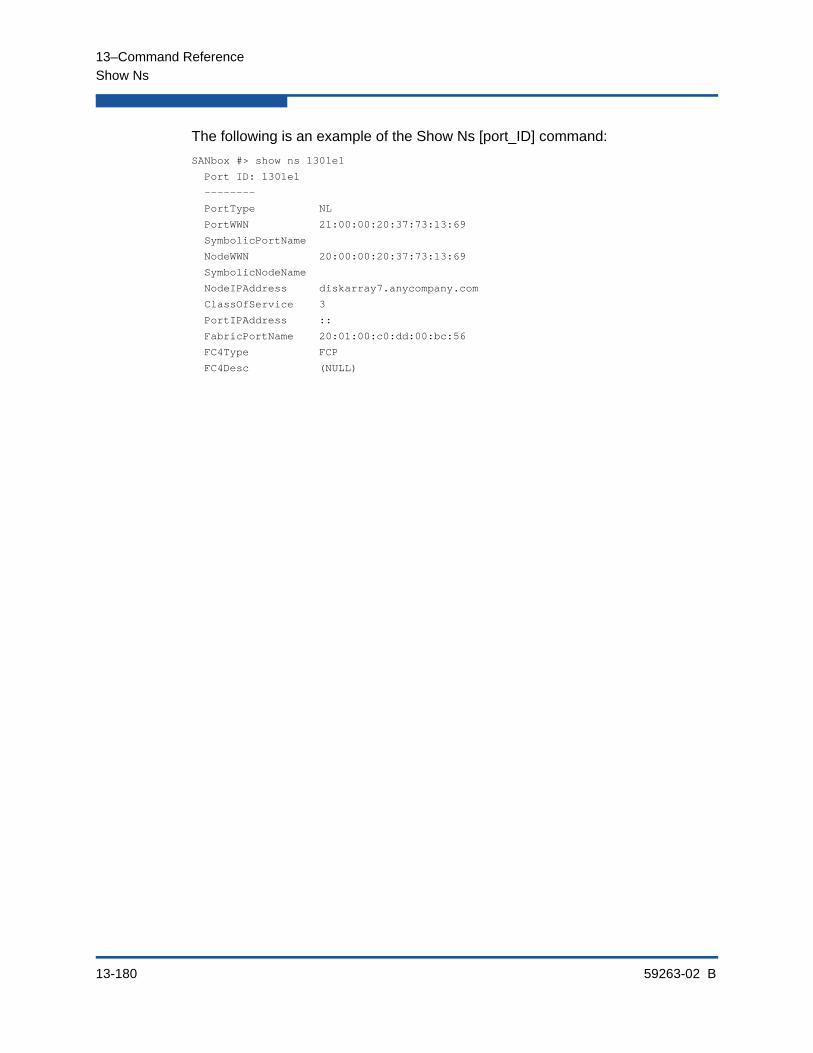
13–Command Reference
Show Ns
13-180 59263-02 B
The following is an example of the Show Ns [port_ID] command:
SANbox #> show ns 1301e1
Port ID: 1301e1
--------
PortType NL
PortWWN 21:00:00:20:37:73:13:69
SymbolicPortName
NodeWWN 20:00:00:20:37:73:13:69
SymbolicNodeName
NodeIPAddress diskarray7.anycompany.com
ClassOfService 3
PortIPAddress ::
FabricPortName 20:01:00:c0:dd:00:bc:56
FC4Type FCP
FC4Desc (NULL)
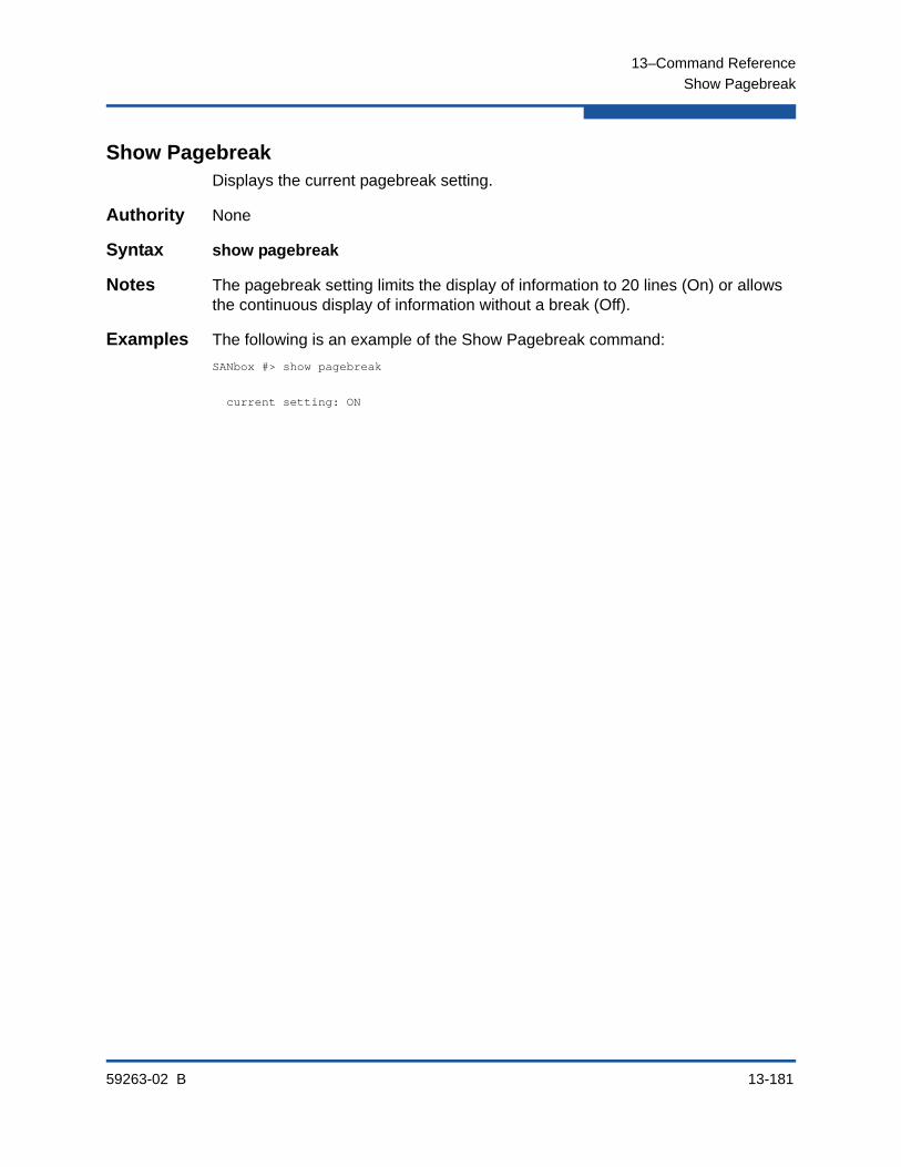
13–Command Reference
Show Pagebreak
59263-02 B 13-181
Show PagebreakDisplays the current pagebreak setting.
Authority None
Syntax show pagebreak
Notes The pagebreak setting limits the display of information to 20 lines (On) or allows the continuous display of information without a break (Off).
Examples The following is an example of the Show Pagebreak command:
SANbox #> show pagebreak
current setting: ON

13–Command Reference
Show Perf
13-182 59263-02 B
Show PerfDisplays port performance in frames/second and bytes/second. If you omit the keyword, the command displays data transmitted (out), data received (in), and total data transmitted and received in frames/second and bytes/second. Transmission rates are expressed in thousands (K) and millions (M).
Authority None
Syntax show perf [port_list]or
show perfbyte [port_list]inbyte [port_list]outbyte [port_list]frame [port_list]inframe [port_list]outframe [port_list]errors [port_list]
Keywords [port_list]
Displays the instantaneous performance data for up to sixteen ports given by [port_list]. [port_list] can be a set of port numbers and ranges delimited by spaces. For example, [0 2 10-15] specifies ports 0, 2, 10, 11, 12, 13, 14, and 15. If you omit [port_list], the command displays performance data for all ports.
byte [port_list]
Displays continuous performance data in total bytes/second transmitted and received for up to sixteen ports given by [port_list]. [port_list] can be a set of port numbers and ranges delimited by spaces. For example, [0 2 10-15] specifies ports 0, 2, 10, 11, 12, 13, 14, and 15. If you omit [port_list], the command displays performance data for ports 0–15. Press any key to stop the display.
inbyte [port_list]
Displays continuous performance data in bytes/second received for the ports given by [port_list]. [port_list] can be a set of port numbers and ranges delimited by spaces. For example, [0 2 10-15] specifies ports 0, 2, 10, 11, 12, 13, 14, and 15. If you omit [port_list], the command displays performance data for ports 0–15. Press any key to stop the display.
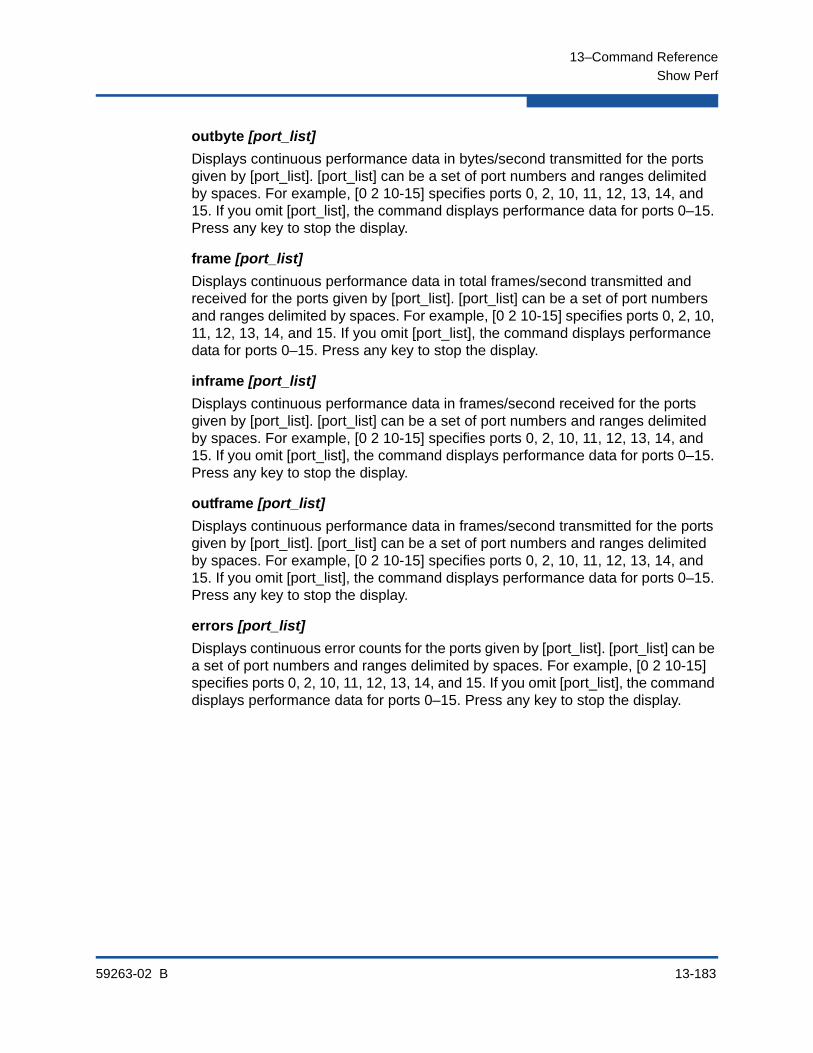
13–Command Reference
Show Perf
59263-02 B 13-183
outbyte [port_list]
Displays continuous performance data in bytes/second transmitted for the ports given by [port_list]. [port_list] can be a set of port numbers and ranges delimited by spaces. For example, [0 2 10-15] specifies ports 0, 2, 10, 11, 12, 13, 14, and 15. If you omit [port_list], the command displays performance data for ports 0–15. Press any key to stop the display.
frame [port_list]
Displays continuous performance data in total frames/second transmitted and received for the ports given by [port_list]. [port_list] can be a set of port numbers and ranges delimited by spaces. For example, [0 2 10-15] specifies ports 0, 2, 10, 11, 12, 13, 14, and 15. If you omit [port_list], the command displays performance data for ports 0–15. Press any key to stop the display.
inframe [port_list]
Displays continuous performance data in frames/second received for the ports given by [port_list]. [port_list] can be a set of port numbers and ranges delimited by spaces. For example, [0 2 10-15] specifies ports 0, 2, 10, 11, 12, 13, 14, and 15. If you omit [port_list], the command displays performance data for ports 0–15. Press any key to stop the display.
outframe [port_list]
Displays continuous performance data in frames/second transmitted for the ports given by [port_list]. [port_list] can be a set of port numbers and ranges delimited by spaces. For example, [0 2 10-15] specifies ports 0, 2, 10, 11, 12, 13, 14, and 15. If you omit [port_list], the command displays performance data for ports 0–15. Press any key to stop the display.
errors [port_list]
Displays continuous error counts for the ports given by [port_list]. [port_list] can be a set of port numbers and ranges delimited by spaces. For example, [0 2 10-15] specifies ports 0, 2, 10, 11, 12, 13, 14, and 15. If you omit [port_list], the command displays performance data for ports 0–15. Press any key to stop the display.

13–Command Reference
Show Perf
13-184 59263-02 B
Examples The following is an example of the Show Perf command:
SANbox #> show perf
Port Bytes/s Bytes/s Bytes/s Frames/s Frames/s Frames/s
Number (in) (out) (total) (in) (out) (total)
------ ------- ------- ------- -------- -------- --------
0 7K 136M 136M 245 68K 68K
1 58K 0 58K 1K 0 1K
2 0 0 0 0 0 0
3 0 0 0 0 0 0
4 0 0 0 0 0 0
5 0 0 0 0 0 0
6 0 7K 7K 0 245 245
7 136M 58K 136M 68K 1K 70K
8 7K 136M 136M 245 68K 68K
9 58K 0 58K 1K 0 1K
10 0 0 0 0 0 0
11 0 0 0 0 0 0
12 0 0 0 0 0 0
13 0 0 0 0 0 0
14 0 7K 7K 0 245 245
15 136M 58K 136M 68K 1K 70K
16 47M 23K 47M 23K 726 24K
17 0 0 0 0 0 0
18 23K 47M 47M 726 23K 24K
19 0 0 0 0 0 0
20 0 0 0 0 0 0
21 0 0 0 0 0 0
22 0 0 0 0 0 0
23 0 0 0 0 0 0
The following is an example of the Show Perf Byte command:
SANbox #> show perf byte
Displaying bytes/sec (total)... (Press any key to stop display)
0 1 2 3 4 5 6 7 8 9 10 11 12 13 14 15
--------------------------------------------------------------------------------
0 0 0 0 0 0 0 0 137M 58K 0 0 0 0 8K 137M
0 0 0 0 0 0 0 0 136M 58K 0 0 0 0 8K 136M
0 0 0 0 0 0 0 0 135M 58K 0 0 0 0 7K 135M
0 0 0 0 0 0 0 0 137M 58K 0 0 0 0 8K 137M
0 0 0 0 0 0 0 0 136M 58K 0 0 0 0 7K 136M
0 0 0 0 0 0 0 0 137M 58K 0 0 0 0 8K 137M
0 0 0 0 0 0 0 0 136M 58K 0 0 0 0 8K 136M
0 0 0 0 0 0 0 0 136M 58K 0 0 0 0 7K 136M
q
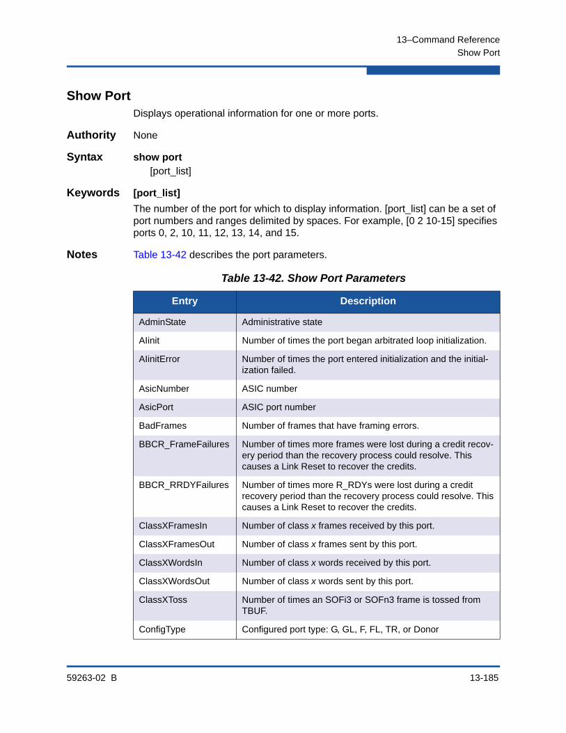
13–Command Reference
Show Port
59263-02 B 13-185
Show PortDisplays operational information for one or more ports.
Authority None
Syntax show port[port_list]
Keywords [port_list]
The number of the port for which to display information. [port_list] can be a set of port numbers and ranges delimited by spaces. For example, [0 2 10-15] specifies ports 0, 2, 10, 11, 12, 13, 14, and 15.
Notes Table 13-42 describes the port parameters.
Table 13-42. Show Port Parameters
Entry Description
AdminState Administrative state
AIinit Number of times the port began arbitrated loop initialization.
AIinitError Number of times the port entered initialization and the initial-ization failed.
AsicNumber ASIC number
AsicPort ASIC port number
BadFrames Number of frames that have framing errors.
BBCR_FrameFailures Number of times more frames were lost during a credit recov-ery period than the recovery process could resolve. This causes a Link Reset to recover the credits.
BBCR_RRDYFailures Number of times more R_RDYs were lost during a credit recovery period than the recovery process could resolve. This causes a Link Reset to recover the credits.
ClassXFramesIn Number of class x frames received by this port.
ClassXFramesOut Number of class x frames sent by this port.
ClassXWordsIn Number of class x words received by this port.
ClassXWordsOut Number of class x words sent by this port.
ClassXToss Number of times an SOFi3 or SOFn3 frame is tossed from TBUF.
ConfigType Configured port type: G, GL, F, FL, TR, or Donor

13–Command Reference
Show Port
13-186 59263-02 B
DecodeError Number of decode errors detected
DownstreamISL Downstream ISL state. True indicates a connection to another switch that is not the principal switch.
POSTFaultCode Fault code from the most recent Power-on self test
POSTStatus Status from the most recent Power-on self test
EpConnects Number of times an E_Port connected through ISL negotia-tion.
EpConnState E_Port connection status
EpIsoReason E_Port isolation reason
FBusy Number of times the switch sent a F_BSY because Class 2 frame could not be delivered within ED_TOV time. The num-ber of class 2 and class 3 fabric busy (F_BSY) frames gener-ated by this port in response to inbound frames. This usually indicates a busy condition on the fabric or N_Port that is pre-venting delivery of this frame.
Flowerrors Number of frames received there were no available credits.
FReject Number of frames from devices that were rejected.
InvalidCRC Invalid CRC detected.
InvalidDestAddr Invalid destination address detected.
IOStreamGuard I/O StreamGuard status
Licensed Port activation status
LinkFailures Number of optical link failures detected by this port. A link fail-ure is a loss of synchronization or a loss of signal while not in the offline state. A loss of signal causes the switch to attempt to re-establish the link. If the link is not re-established, a link failure is counted. A link reset is performed after a link failure.
LinkSpeed Port transmission speed
LinkState Port activity status
LIP_AL_PD_ALPS Number of F7, AL_PS LIPs, or AL_PD (vendor specific) resets, performed.
LIP_F7_AL_PS This LIP is used to reinitialize the loop. An L_Port, identified by AL_PS, may have noticed a performance degradation and is trying to restore the loop.
Table 13-42. Show Port Parameters (Continued)
Entry Description

13–Command Reference
Show Port
59263-02 B 13-187
LIP_F8_AL_PS This LIP denotes a loop failure detected by the L_Port identi-fied by AL_PS.
LIP_F7_F7 A loop initialization primitive frame used to acquire a valid AL_PA.
LIP_F8_F7 A loop initialization primitive frame used to indicate that a loop failure has been detected at the receiver.
Login Number of device logins
LoginStatus Device login status for the port: LoggedIn or NotLoggedIn
Logout Number of device logouts that have occurred on the port
LongFramesIn Number of incidents when one or more frames that are greater than the maximum size were received
LoopTimeouts A two (2) second timeout, as specified by FC-AL-2.
LossOfSync Number of synchronization losses (>100 ms) detected by this port. A loss of synchronization is detected by the receipt of an invalid transmission word.
LostFrames Number of incidents of lost frames.
LostRRDYs Number of incidents of lost Receiver_Ready (R_RDY) primi-tives
MaxCredit Maximum number of port buffer credits
MediaSpeeds Possible transmission speeds for the port
MediaPartNumber Transceiver vendor part number
MediaRevision Transceiver revision
MediaType Media physical variant. The variant indicates speed, media, transmitter, and distance. The media designator may be M5 (multimode 50 micron), M6 (multimode 62.5 micron), or MX. MX indicates that the media supports both multimode 50 and 62.5 micron.
MediaVendor Transceiver manufacturer
MediaVendorID Transceiver manufacturer identifier
OperationalState Operational state
PerfTuningMode AutoPerfTuning status
Table 13-42. Show Port Parameters (Continued)
Entry Description

13–Command Reference
Show Port
13-188 59263-02 B
PortID Fibre Channel port address
PortWWN Worldwide port name
PrimSeqErrors Number of primitive sequence errors detected
RunningType Operational port type: F, FL, E, or Unknown
RxLinkResets Number of link reset primitives received from an attached device
RxOfflineSeq Number of offline sequences (OLSs) received. An OLS is issued for link initialization, a Receive & Recognize Not_Operational (NOS) state, or to enter the offline state.
ShortFramesIn Number of incidents when one or more frames that are less than the minimum size were received
SymbolicName Port symbolic name
SyncStatus Synchronization status: SyncAcquired, SyncLost
TestFaultCode Fault code from the most recent port test
TestStatus Status from the most recent port test
TotalErrors Total number of errors detected on the port since the last port or switch reset
TotalLinkResets Total number of link resets since the last port or switch reset
TotalLIPsRecvd Number of loop initialization primitive frames received by this port.
TotalLIPsXmitd Number of loop initialization primitive frames transmitted by this port.
TotalOfflineSeq Total number of Offline Sequences issued and received by this port.
TotalRxFrames Total number of frames received by this port.
TotalRxWords Total number of words received by this port.
TotalTxFrames Total number of frames issued by this port.
TotalTxWords Total number of words issued by this port.
TxLinkResets Number of Link Resets issued by this port.
TxOfflineSeq Number of Offline Sequences issued by this port.
Table 13-42. Show Port Parameters (Continued)
Entry Description
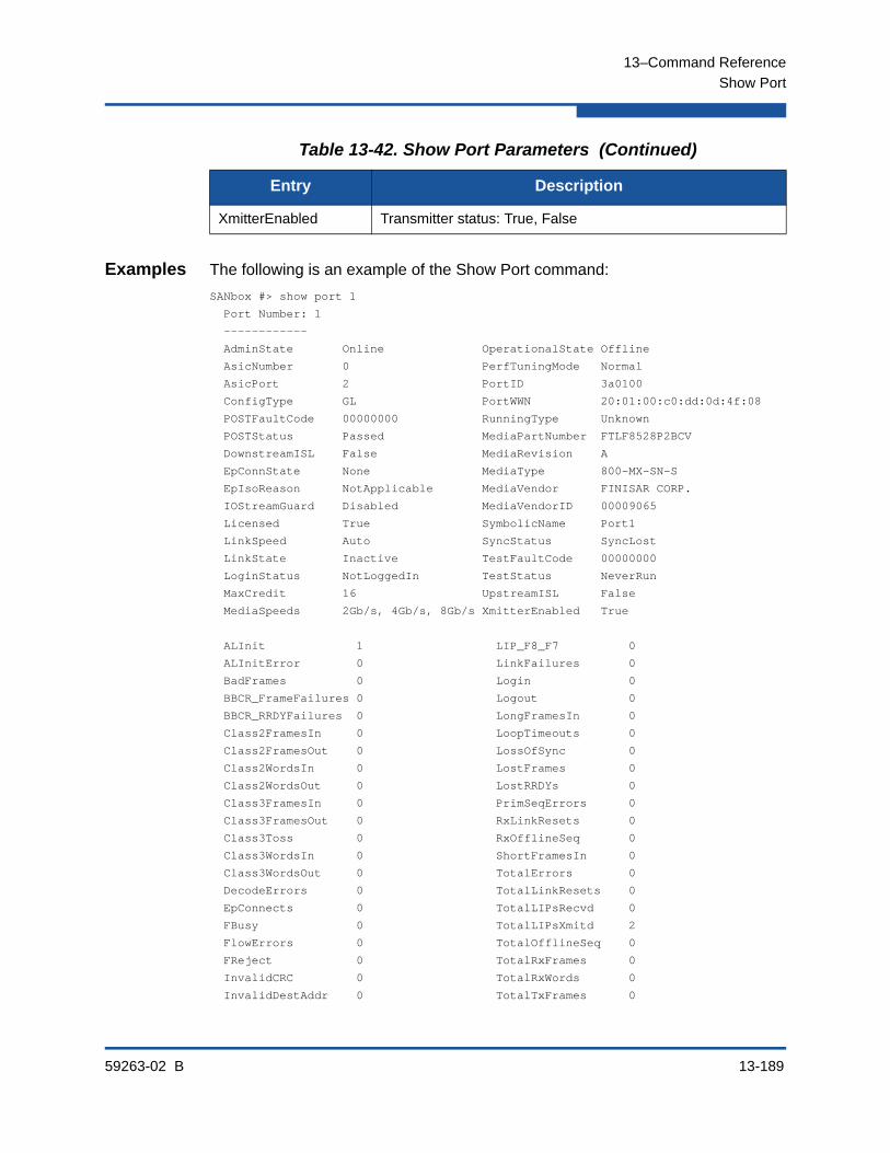
13–Command Reference
Show Port
59263-02 B 13-189
Examples The following is an example of the Show Port command:
SANbox #> show port 1
Port Number: 1
------------
AdminState Online OperationalState Offline
AsicNumber 0 PerfTuningMode Normal
AsicPort 2 PortID 3a0100
ConfigType GL PortWWN 20:01:00:c0:dd:0d:4f:08
POSTFaultCode 00000000 RunningType Unknown
POSTStatus Passed MediaPartNumber FTLF8528P2BCV
DownstreamISL False MediaRevision A
EpConnState None MediaType 800-MX-SN-S
EpIsoReason NotApplicable MediaVendor FINISAR CORP.
IOStreamGuard Disabled MediaVendorID 00009065
Licensed True SymbolicName Port1
LinkSpeed Auto SyncStatus SyncLost
LinkState Inactive TestFaultCode 00000000
LoginStatus NotLoggedIn TestStatus NeverRun
MaxCredit 16 UpstreamISL False
MediaSpeeds 2Gb/s, 4Gb/s, 8Gb/s XmitterEnabled True
ALInit 1 LIP_F8_F7 0
ALInitError 0 LinkFailures 0
BadFrames 0 Login 0
BBCR_FrameFailures 0 Logout 0
BBCR_RRDYFailures 0 LongFramesIn 0
Class2FramesIn 0 LoopTimeouts 0
Class2FramesOut 0 LossOfSync 0
Class2WordsIn 0 LostFrames 0
Class2WordsOut 0 LostRRDYs 0
Class3FramesIn 0 PrimSeqErrors 0
Class3FramesOut 0 RxLinkResets 0
Class3Toss 0 RxOfflineSeq 0
Class3WordsIn 0 ShortFramesIn 0
Class3WordsOut 0 TotalErrors 0
DecodeErrors 0 TotalLinkResets 0
EpConnects 0 TotalLIPsRecvd 0
FBusy 0 TotalLIPsXmitd 2
FlowErrors 0 TotalOfflineSeq 0
FReject 0 TotalRxFrames 0
InvalidCRC 0 TotalRxWords 0
InvalidDestAddr 0 TotalTxFrames 0
XmitterEnabled Transmitter status: True, False
Table 13-42. Show Port Parameters (Continued)
Entry Description
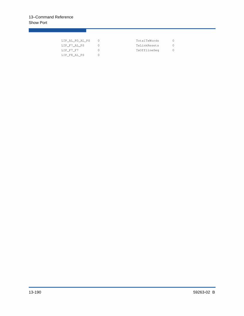
13–Command Reference
Show Port
13-190 59263-02 B
LIP_AL_PD_AL_PS 0 TotalTxWords 0
LIP_F7_AL_PS 0 TxLinkResets 0
LIP_F7_F7 0 TxOfflineSeq 0
LIP_F8_AL_PS 0
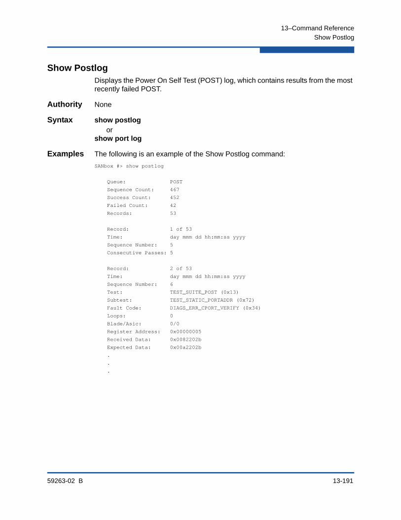
13–Command Reference
Show Postlog
59263-02 B 13-191
Show PostlogDisplays the Power On Self Test (POST) log, which contains results from the most recently failed POST.
Authority None
Syntax show postlogor
show port log
Examples The following is an example of the Show Postlog command:
SANbox #> show postlog
Queue: POST
Sequence Count: 467
Success Count: 452
Failed Count: 42
Records: 53
Record: 1 of 53
Time: day mmm dd hh:mm:ss yyyy
Sequence Number: 5
Consecutive Passes: 5
Record: 2 of 53
Time: day mmm dd hh:mm:ss yyyy
Sequence Number: 6
Test: TEST_SUITE_POST (0x13)
Subtest: TEST_STATIC_PORTADDR (0x72)
Fault Code: DIAGS_ERR_CPORT_VERIFY (0x34)
Loops: 0
Blade/Asic: 0/0
Register Address: 0x00000005
Received Data: 0x0082202b
Expected Data: 0x00a2202b
.
.
.

13–Command Reference
Show Setup Callhome
13-192 59263-02 B
Show Setup CallhomeDisplays the Call Home database configuration.
Authority None
Syntax show setup callhome
Examples The following is an example of the Show Setup Callhome command:
SANbox #> show setup callhome
Callhome Information
--------------------
PrimarySMTPServerAddr 0.0.0.0
PrimarySMTPServerPort 25
PrimarySMTPServerEnabled False
SecondarySMTPServerAddr 0.0.0.0
SecondarySMTPServerPort 25
SecondarySMTPServerEnabled False
ContactEmailAddress [email protected]
PhoneNumber <undefined>
StreetAddress <undefined>
FromEmailAddress [email protected]
ReplyToEmailAddress [email protected]
ThrottleDupsEnabled True
+ indicates active SMTP server
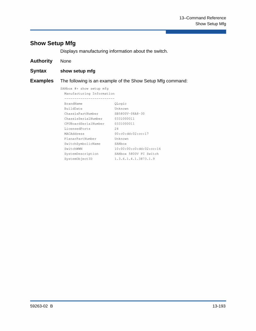
13–Command Reference
Show Setup Mfg
59263-02 B 13-193
Show Setup MfgDisplays manufacturing information about the switch.
Authority None
Syntax show setup mfg
Examples The following is an example of the Show Setup Mfg command:
SANbox #> show setup mfg
Manufacturing Information
-------------------------
BrandName QLogic
BuildDate Unknown
ChassisPartNumber SB5800V-08A8-30
ChassisSerialNumber 0331000011
CPUBoardSerialNumber 0331000011
LicensedPorts 24
MACAddress 00:c0:dd:02:cc:17
PlanarPartNumber Unknown
SwitchSymbolicName SANbox
SwitchWWN 10:00:00:c0:dd:02:cc:16
SystemDescription SANbox 5800V FC Switch
SystemObjectID 1.3.6.1.4.1.3873.1.9
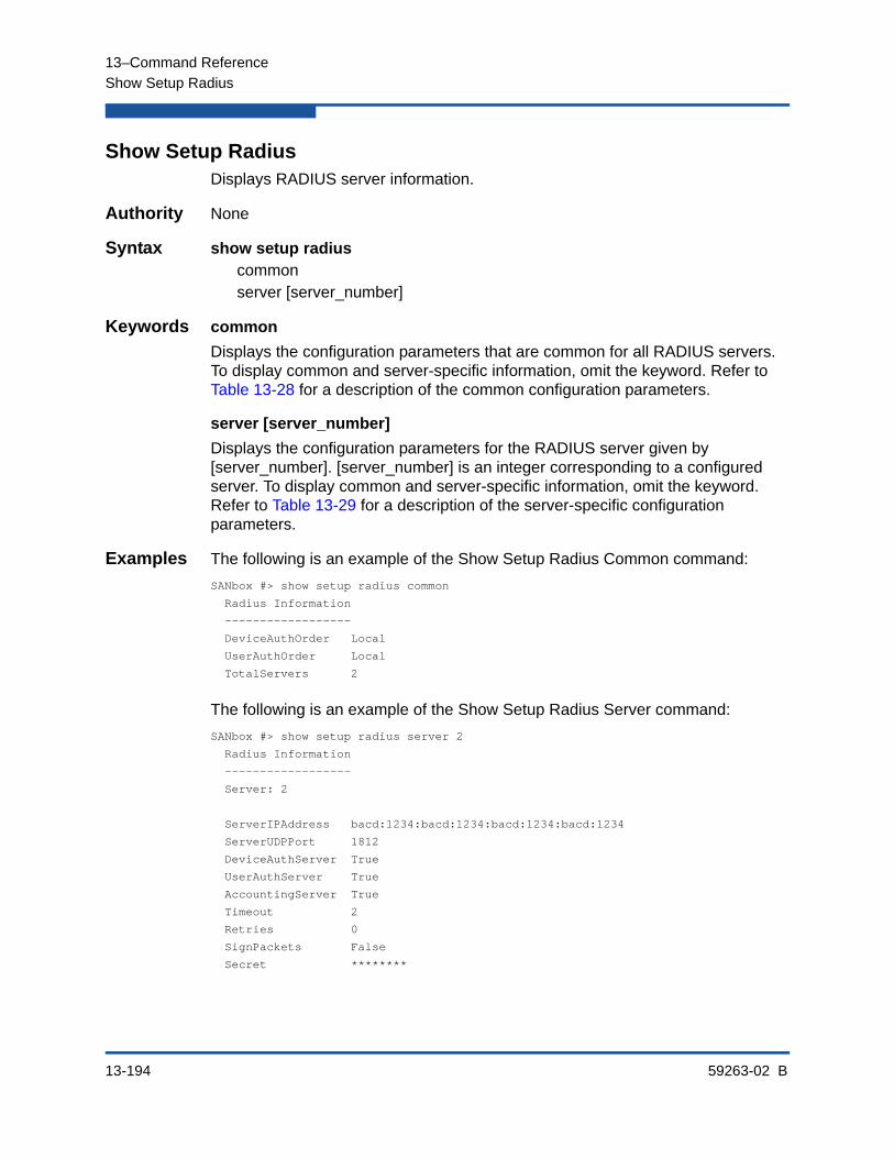
13–Command Reference
Show Setup Radius
13-194 59263-02 B
Show Setup RadiusDisplays RADIUS server information.
Authority None
Syntax show setup radiuscommonserver [server_number]
Keywords common
Displays the configuration parameters that are common for all RADIUS servers. To display common and server-specific information, omit the keyword. Refer to Table 13-28 for a description of the common configuration parameters.
server [server_number]
Displays the configuration parameters for the RADIUS server given by [server_number]. [server_number] is an integer corresponding to a configured server. To display common and server-specific information, omit the keyword. Refer to Table 13-29 for a description of the server-specific configuration parameters.
Examples The following is an example of the Show Setup Radius Common command:
SANbox #> show setup radius common
Radius Information
------------------
DeviceAuthOrder Local
UserAuthOrder Local
TotalServers 2
The following is an example of the Show Setup Radius Server command:
SANbox #> show setup radius server 2
Radius Information
------------------
Server: 2
ServerIPAddress bacd:1234:bacd:1234:bacd:1234:bacd:1234
ServerUDPPort 1812
DeviceAuthServer True
UserAuthServer True
AccountingServer True
Timeout 2
Retries 0
SignPackets False
Secret ********
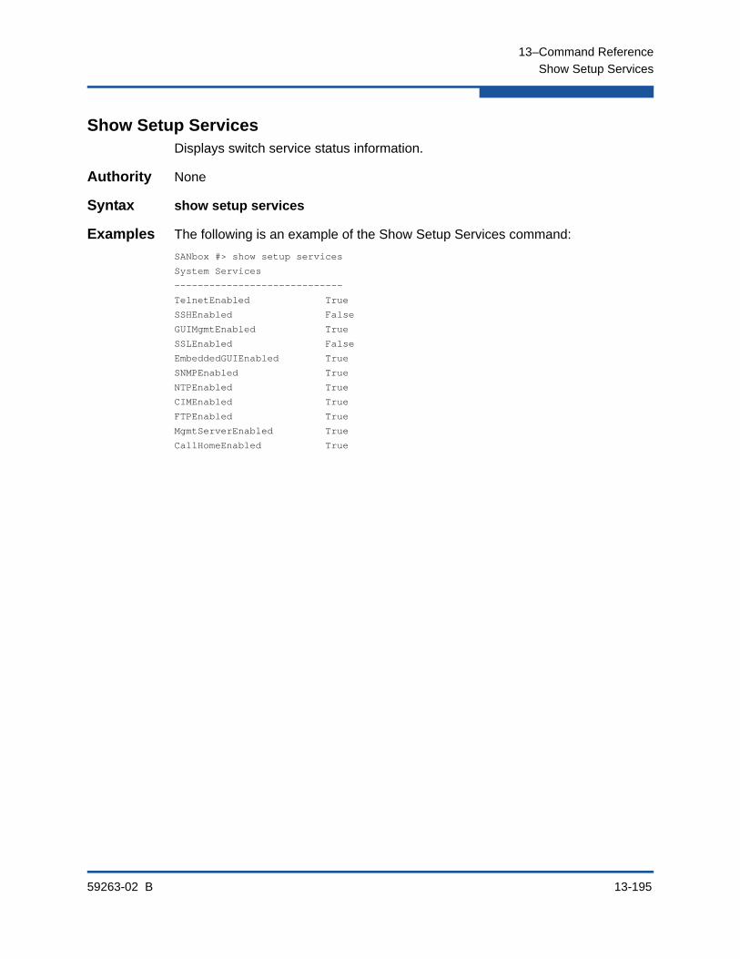
13–Command Reference
Show Setup Services
59263-02 B 13-195
Show Setup ServicesDisplays switch service status information.
Authority None
Syntax show setup services
Examples The following is an example of the Show Setup Services command:
SANbox #> show setup services
System Services
-----------------------------
TelnetEnabled True
SSHEnabled False
GUIMgmtEnabled True
SSLEnabled False
EmbeddedGUIEnabled True
SNMPEnabled True
NTPEnabled True
CIMEnabled True
FTPEnabled True
MgmtServerEnabled True
CallHomeEnabled True
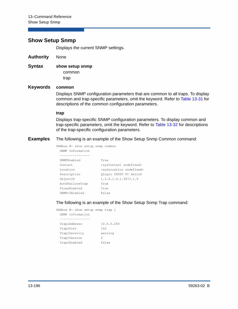
13–Command Reference
Show Setup Snmp
13-196 59263-02 B
Show Setup SnmpDisplays the current SNMP settings.
Authority None
Syntax show setup snmpcommontrap
Keywords common
Displays SNMP configuration parameters that are common to all traps. To display common and trap-specific parameters, omit the keyword. Refer to Table 13-31 for descriptions of the common configuration parameters.
trap
Displays trap-specific SNMP configuration parameters. To display common and trap-specific parameters, omit the keyword. Refer to Table 13-32 for descriptions of the trap-specific configuration parameters.
Examples The following is an example of the Show Setup Snmp Common command:
SANbox #> show setup snmp common
SNMP Information
----------------
SNMPEnabled True
Contact <sysContact undefined>
Location <sysLocation undefined>
Description QLogic 5800V FC Switch
ObjectID 1.3.6.1.4.1.3873.1.9
AuthFailureTrap True
ProxyEnabled True
SNMPv3Enabled False
The following is an example of the Show Setup Snmp Trap command:
SANbox #> show setup snmp trap 1
SNMP Information
----------------
Trap1Address 10.0.0.254
Trap1Port 162
Trap1Severity warning
Trap1Version 2
Trap1Enabled False

13–Command Reference
Show Setup System
59263-02 B 13-197
Show Setup SystemDisplays network, logging, NTP server, and timer parameters on the switch.
Authority None
Syntax show setup systemdnsipv4ipv6loggingntptimers
Keywords dns
Displays DNS host name configuration parameters. To display all system configuration parameters, omit the keyword. Refer to Table 13-33 for descriptions of the DNS host name configuration parameters.
ipv4
Displays switch IPv4 Ethernet configuration parameters. To display all system configuration parameters, omit the keyword. Refer to Table 13-34 for descriptions of the IPv4 Ethernet configuration parameters.
ipv6
Displays switch IP version 6 Ethernet configuration parameters. To display all system configuration parameters, omit the keyword. Refer to Table 13-35 for descriptions of the IP version 6 Ethernet configuration parameters.
logging
Displays event logging configuration parameters. To display all system configuration parameters, omit the keyword. Refer to Table 13-36 for descriptions of the event logging configuration parameters.
ntp
Displays NTP server configuration parameters. To display all system configuration parameters, omit the keyword. Refer to Table 13-37 for descriptions of the NTP server configuration parameters.
timers
Displays timer configuration parameters. To display all system configuration parameters, omit the keyword. Refer to Table 13-38 for descriptions of the timer configuration parameters.
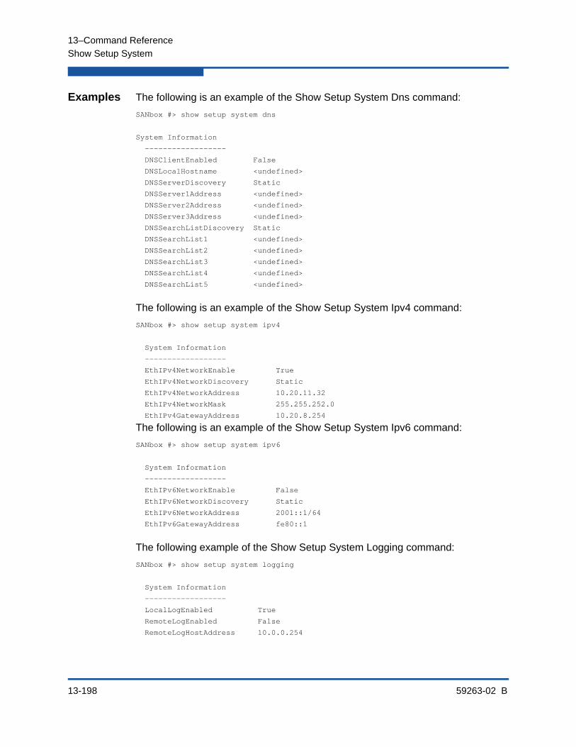
13–Command Reference
Show Setup System
13-198 59263-02 B
Examples The following is an example of the Show Setup System Dns command:
SANbox #> show setup system dns
System Information
------------------
DNSClientEnabled False
DNSLocalHostname <undefined>
DNSServerDiscovery Static
DNSServer1Address <undefined>
DNSServer2Address <undefined>
DNSServer3Address <undefined>
DNSSearchListDiscovery Static
DNSSearchList1 <undefined>
DNSSearchList2 <undefined>
DNSSearchList3 <undefined>
DNSSearchList4 <undefined>
DNSSearchList5 <undefined>
The following is an example of the Show Setup System Ipv4 command:
SANbox #> show setup system ipv4
System Information
------------------
EthIPv4NetworkEnable True
EthIPv4NetworkDiscovery Static
EthIPv4NetworkAddress 10.20.11.32
EthIPv4NetworkMask 255.255.252.0
EthIPv4GatewayAddress 10.20.8.254
The following is an example of the Show Setup System Ipv6 command:
SANbox #> show setup system ipv6
System Information
------------------
EthIPv6NetworkEnable False
EthIPv6NetworkDiscovery Static
EthIPv6NetworkAddress 2001::1/64
EthIPv6GatewayAddress fe80::1
The following example of the Show Setup System Logging command:
SANbox #> show setup system logging
System Information
------------------
LocalLogEnabled True
RemoteLogEnabled False
RemoteLogHostAddress 10.0.0.254

13–Command Reference
Show Setup System
59263-02 B 13-199
The following is an example of the Show Setup System Ntp command:
SANbox #> show setup system ntp
System Information
------------------
NTPClientEnabled False
NTPServerDiscovery Static
NTPServerAddress 51.68.85.102
The following example of the Show Setup System Timers command:
SANbox #> show setup system timers
System Information
------------------
AdminTimeout 30
InactivityTimeout 0
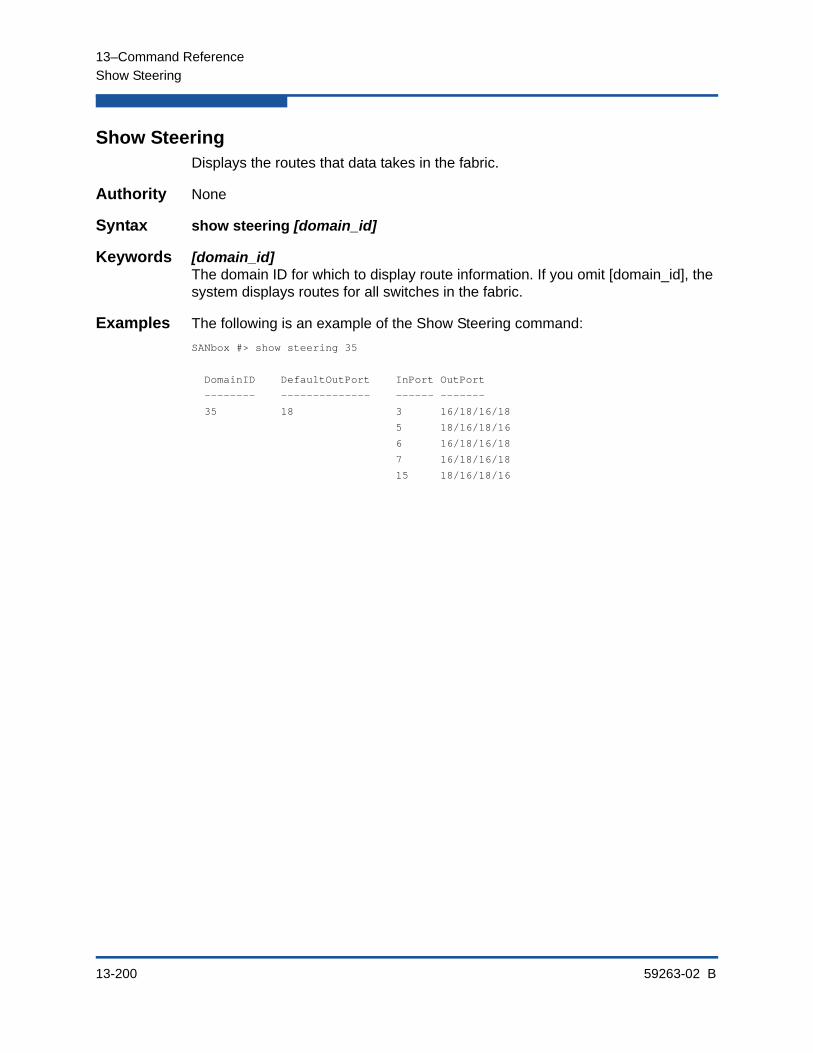
13–Command Reference
Show Steering
13-200 59263-02 B
Show SteeringDisplays the routes that data takes in the fabric.
Authority None
Syntax show steering [domain_id]
Keywords [domain_id]The domain ID for which to display route information. If you omit [domain_id], the system displays routes for all switches in the fabric.
Examples The following is an example of the Show Steering command:
SANbox #> show steering 35
DomainID DefaultOutPort InPort OutPort
-------- -------------- ------ -------
35 18 3 16/18/16/18
5 18/16/18/16
6 16/18/16/18
7 16/18/16/18
15 18/16/18/16
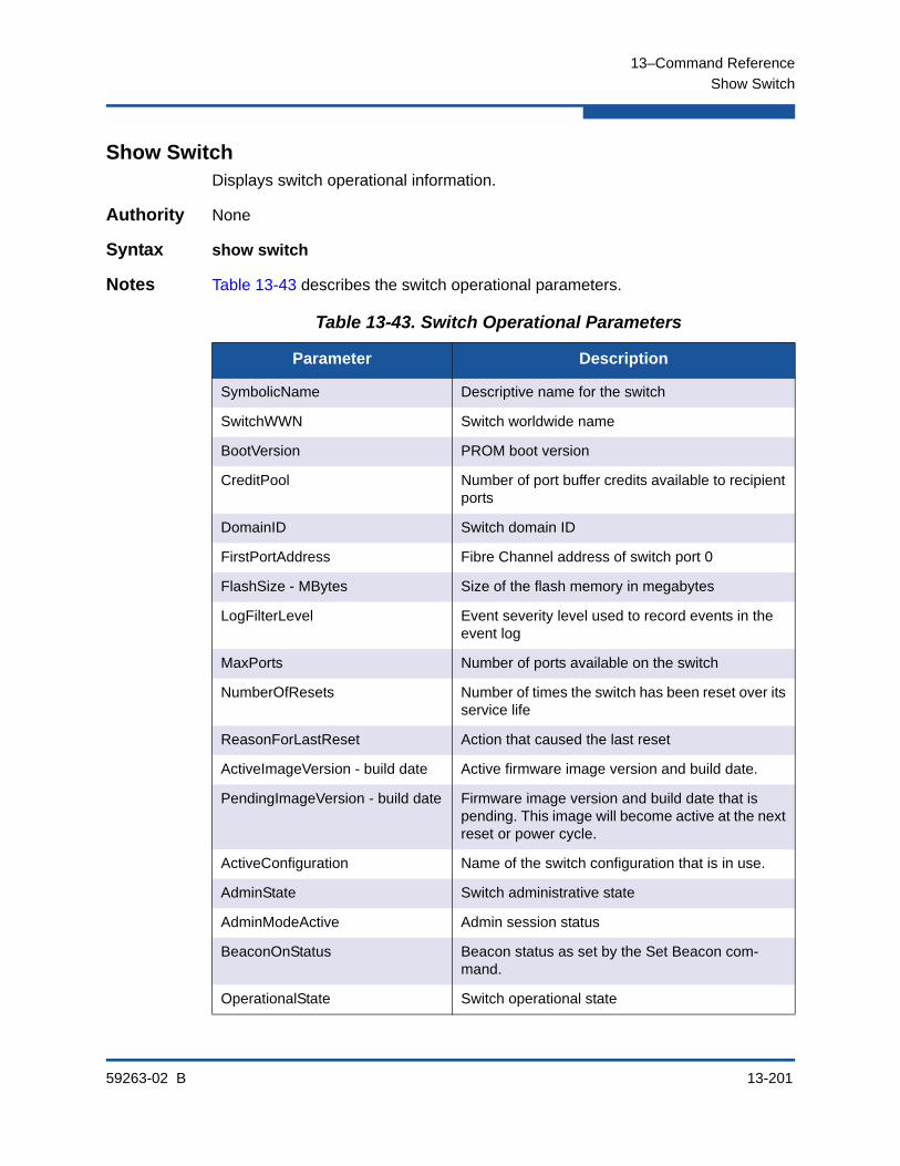
13–Command Reference
Show Switch
59263-02 B 13-201
Show SwitchDisplays switch operational information.
Authority None
Syntax show switch
Notes Table 13-43 describes the switch operational parameters.
Table 13-43. Switch Operational Parameters
Parameter Description
SymbolicName Descriptive name for the switch
SwitchWWN Switch worldwide name
BootVersion PROM boot version
CreditPool Number of port buffer credits available to recipient ports
DomainID Switch domain ID
FirstPortAddress Fibre Channel address of switch port 0
FlashSize - MBytes Size of the flash memory in megabytes
LogFilterLevel Event severity level used to record events in the event log
MaxPorts Number of ports available on the switch
NumberOfResets Number of times the switch has been reset over its service life
ReasonForLastReset Action that caused the last reset
ActiveImageVersion - build date Active firmware image version and build date.
PendingImageVersion - build date Firmware image version and build date that is pending. This image will become active at the next reset or power cycle.
ActiveConfiguration Name of the switch configuration that is in use.
AdminState Switch administrative state
AdminModeActive Admin session status
BeaconOnStatus Beacon status as set by the Set Beacon com-mand.
OperationalState Switch operational state

13–Command Reference
Show Switch
13-202 59263-02 B
Examples The following is an example of the Show Switch command:
SANbox #> show switch
Switch Information
------------------
SymbolicName SANbox
SwitchWWN 10:00:00:c0:dd:00:bc:56
BootVersion Vx.x.x.x-0 (day month date time year)
CreditPool 0
DomainID 19 (0x13)
FirstPortAddress 130000
FlashSize - MBytes 128
LogFilterLevel Critical
MaxPorts 24
NumberOfResets 15
ReasonForLastReset PowerUp
ActiveImageVersion - build date Vx.x.x.0 (day month date time year)
PendingImageVersion - build date Vx.x.x.0 (day month date time year)
ActiveConfiguration default
AdminState Online
AdminModeActive False
BeaconOnStatus Off
OperationalState Online
PrincipalSwitchRole False
POSTFaultCode 00000000
POSTStatus Passed
TestFaultCode 00000000
TestStatus NeverRun
BoardTemp (1) - Degrees Celsius 32
SwitchTemperatureStatus Normal
PrincipalSwitchRole Principal switch status. True indicates that this switch is the principal switch.
POSTFaultCode Fault code from the most recent Power-on self test
POSTStatus Status from the most recent Power-on self test
TestFaultCode Fault code from the most recent switch test
TestStatus Status from the most recent switch test
BoardTemp (1) - Degrees Celsius Internal switch temperature at circuit board sensor 1.
SwitchTemperatureStatus Switch temperature status: Normal, Warning, Fail-ure.
Table 13-43. Switch Operational Parameters (Continued)
Parameter Description
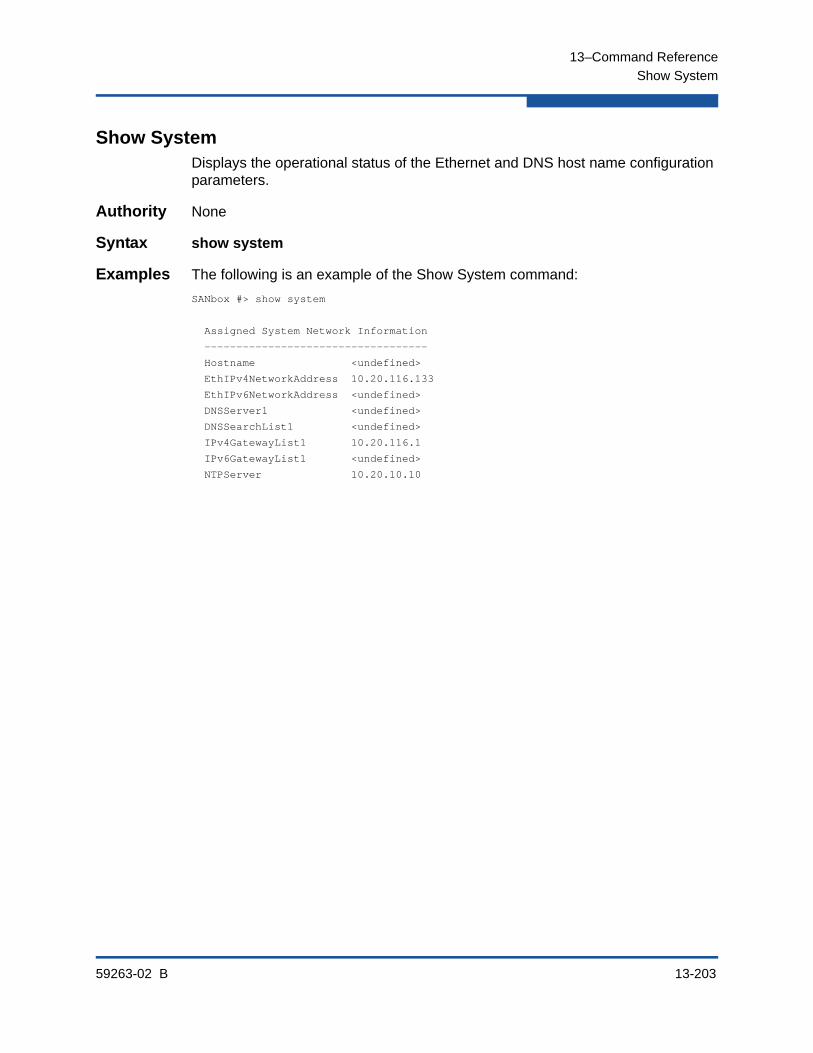
13–Command Reference
Show System
59263-02 B 13-203
Show SystemDisplays the operational status of the Ethernet and DNS host name configuration parameters.
Authority None
Syntax show system
Examples The following is an example of the Show System command:
SANbox #> show system
Assigned System Network Information
-----------------------------------
Hostname <undefined>
EthIPv4NetworkAddress 10.20.116.133
EthIPv6NetworkAddress <undefined>
DNSServer1 <undefined>
DNSSearchList1 <undefined>
IPv4GatewayList1 10.20.116.1
IPv6GatewayList1 <undefined>
NTPServer 10.20.10.10

13–Command Reference
Show Testlog
13-204 59263-02 B
Show TestlogDisplays the contents of the diagnostic field test log file.
Authority None
Syntax show testlogor
show test log
Examples The following is an example of the Show Testlog command:
SANbox #> show testlog
Queue: UID
Sequence Count: 17
Success Count: 10
Failed Count: 7
Records: 11
Record: 1 of 11
Time: Mon Sep 15 16:56:49 2008
Sequence Number: 1
Test: TEST_ONLINE (0x61)
Subtest: TEST_ONLINE (0x61)
Fault Code: DIAGS_ERR_INVALID_PORT_TYPE (0x14)
Loops: 0
Tx Blade/Asic/Port: 0/0/0
Record: 2 of 11
Time: Mon Sep 15 17:02:38 2008
Sequence Number: 3
Test: TEST_ONLINE (0x61)
Subtest: TEST_ONLINE (0x61)
Fault Code: DIAGS_ERR_INVALID_PORT_TYPE (0x14)
Loops: 0
Tx Blade/Asic/Port: 0/0/0
Record: 3 of 11
Time: Mon Sep 15 17:02:38 2008
Sequence Number: 2
Consecutive Passes: 1
.
.
.

13–Command Reference
Show Timezone
59263-02 B 13-205
Show TimezoneDisplays the current time zone setting.
Authority None
Syntax show timezone
Examples The following is an example of the Show Timezone command:
SANbox #> show timezone
America/Chicago

13–Command Reference
Show Topology
13-206 59263-02 B
Show TopologyDisplays information about devices connected to the switch.
Authority None
Syntax show topology [port_number]
Keywords [port_number]
Displays the devices connected to the port given by [port_number].
Examples The following is an example of the Show Topology command:
SANbox #> show topology
Unique ID Key
-------------
A = ALPA, D = Domain ID, P = Port ID
Port Local Local Remote Remote Unique
Number Type PortWWN Type NodeWWN ID
------ ----- ------- ------ ------- ------
5 F 20:05:00:c0:dd:00:bd:ec N 20:00:00:00:c9:22:1e:93 010500 P
10 E 20:0a:00:c0:dd:00:bd:ec E 10:00:00:c0:dd:00:80:21 4(0x4) D
The following is an example of the Show Topology command for port 1:
SANbox #> show topology 1
Local Link Information
----------------------
PortNumber 1
PortID 650100
PortWWN 20:01:00:c0:dd:00:91:11
PortType F
Remote Link Information
-----------------------
Device 0
NodeWWN 50:80:02:00:00:06:d5:38
PortType NL
Description (NULL)
IPv4Address 0.0.0.0
IPv6Address fc00:1234:5678:9abc:def0:1234:5678:9abc
Device 1
NodeWWN 20:00:00:20:37:2b:08:c9
PortType NL
Description (NULL)
IPv4Address 0.0.0.0
IPv6Address fc00:1234:5678:9abc:def0:1234:5678:9efg
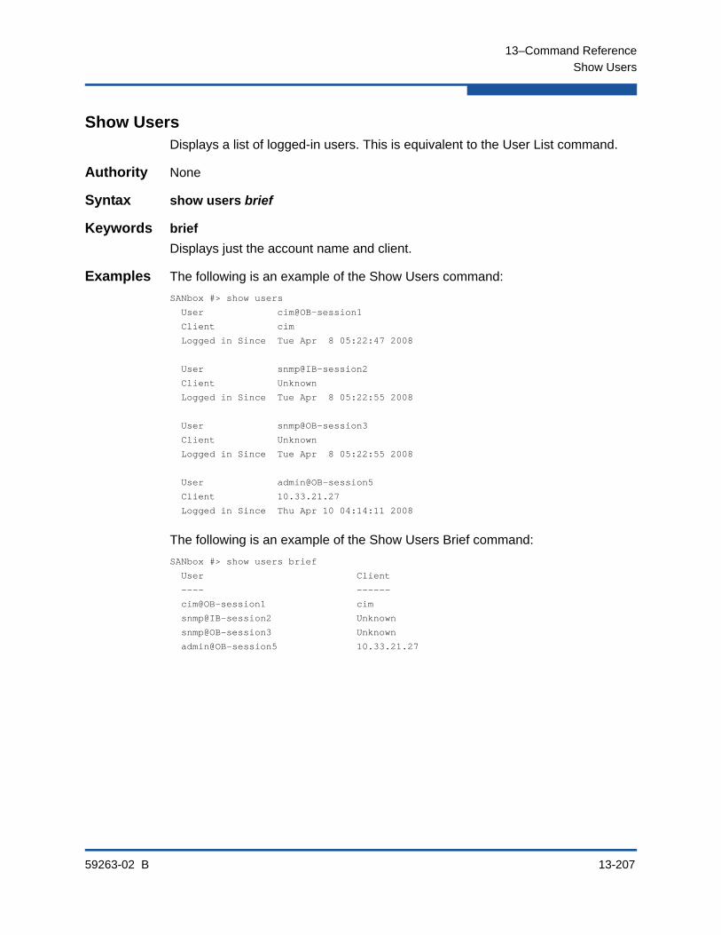
13–Command Reference
Show Users
59263-02 B 13-207
Show UsersDisplays a list of logged-in users. This is equivalent to the User List command.
Authority None
Syntax show users brief
Keywords brief
Displays just the account name and client.
Examples The following is an example of the Show Users command:
SANbox #> show users
User cim@OB-session1
Client cim
Logged in Since Tue Apr 8 05:22:47 2008
User snmp@IB-session2
Client Unknown
Logged in Since Tue Apr 8 05:22:55 2008
User snmp@OB-session3
Client Unknown
Logged in Since Tue Apr 8 05:22:55 2008
User admin@OB-session5
Client 10.33.21.27
Logged in Since Thu Apr 10 04:14:11 2008
The following is an example of the Show Users Brief command:
SANbox #> show users brief
User Client
---- ------
cim@OB-session1 cim
snmp@IB-session2 Unknown
snmp@OB-session3 Unknown
admin@OB-session5 10.33.21.27

13–Command Reference
Show Version
13-208 59263-02 B
Show VersionDisplays an introductory set of information about operational attributes of the switch. This command is equivalent to the Show About command.
Authority None
Syntax show version
Notes Table 13-44 describes the Show Version command display entries.
Table 13-44. Show Version Display Entries
Entry Description
SystemDescription Switch system description
HostName DNS host name
EthIPv4NetworkAddress Switch IP address, version 4
EthIPv6NetworkAddress Switch IP address, version 6
MacAddress Switch MAC address
WorldWideName Switch worldwide name
ChassisSerialNumber Switch serial number
SymbolicName Switch symbolic name
ActiveSWVersion Firmware version
ActiveTimestamp Date and time that the firmware was activated
POSTStatus Results of the Power-on Self Test
LicensedPorts Number of licensed ports
SwitchMode Full Fabric indicates that the switch operates with the standard Fibre Channel port types: G, GL, F, FL, E, TR.
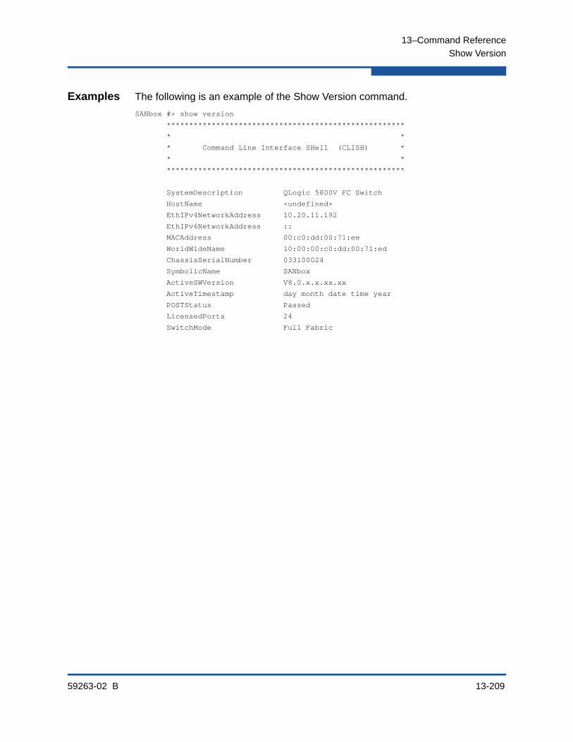
13–Command Reference
Show Version
59263-02 B 13-209
Examples The following is an example of the Show Version command.
SANbox #> show version
*****************************************************
* *
* Command Line Interface SHell (CLISH) *
* *
*****************************************************
SystemDescription QLogic 5800V FC Switch
HostName <undefined>
EthIPv4NetworkAddress 10.20.11.192
EthIPv6NetworkAddress ::
MACAddress 00:c0:dd:00:71:ee
WorldWideName 10:00:00:c0:dd:00:71:ed
ChassisSerialNumber 033100024
SymbolicName SANbox
ActiveSWVersion V8.0.x.x.xx.xx
ActiveTimestamp day month date time year
POSTStatus Passed
LicensedPorts 24
SwitchMode Full Fabric

13–Command Reference
Shutdown
13-210 59263-02 B
ShutdownTerminates all data transfers on the switch at convenient points and closes the Telnet session. Always power cycle the switch after entering this command.
Authority Admin session
Syntax shutdown
Notes When the shutdown is complete, the Heartbeat LED is extinguished.

13–Command Reference
Snmpv3user
59263-02 B 13-211
Snmpv3userManages SNMP version 3 user accounts on the switch.
Authority Admin session except for the List keyword
Syntax snmpv3useradddelete [account]editlist
Keywords add
Creates an SNMP version 3 user account, prompting you for the parameters that are described in Table 13-45.
delete [account]
Deletes the SNMP version 3 user account given by [account].
edit
Modifies an SNMP version 3 user account, prompting you first for the account name to edit. For a description of the SNMP version 3 user account parameters, refer to Table 13-45.
Table 13-45. SNMP Version 3 User Account Parameters
Parameter Description
Username Account user name
Group Group type: Read-Only or Read-Write. The default is Read-Only.
Authentication Enables (True) or disables (False) authentication. The default is False.
AuthType Authentication type can be MD5 or SHA.
AuthPhrase Authentication phrase
Confirm AuthPhrase Authentication phrase confirmation. Re-enter the phrase.
Privacy Enables (True) or disables (False) privacy. The default is False.
PrivType Privacy type. The default is DES.
PrivPhrase Privacy phrase
Confirm PrivPhrase Privacy phrase confirmation. Re-enter the phrase.
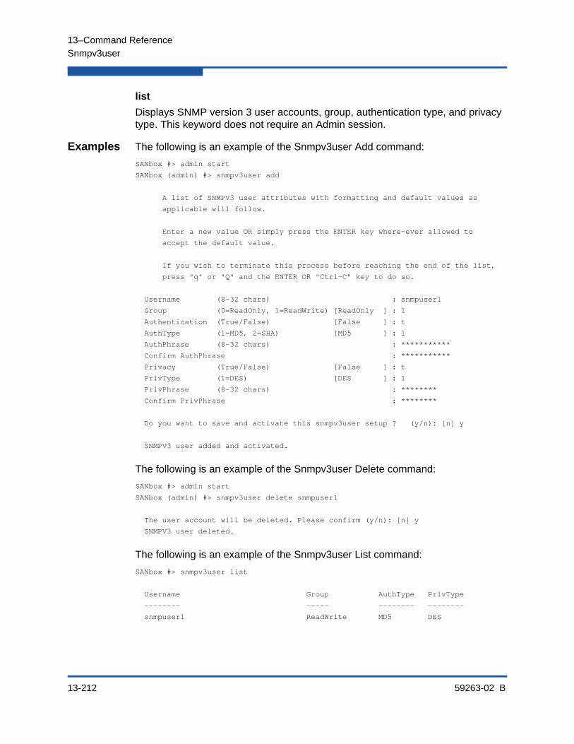
13–Command Reference
Snmpv3user
13-212 59263-02 B
list
Displays SNMP version 3 user accounts, group, authentication type, and privacy type. This keyword does not require an Admin session.
Examples The following is an example of the Snmpv3user Add command:
SANbox #> admin start
SANbox (admin) #> snmpv3user add
A list of SNMPV3 user attributes with formatting and default values as
applicable will follow.
Enter a new value OR simply press the ENTER key where-ever allowed to
accept the default value.
If you wish to terminate this process before reaching the end of the list,
press "q" or "Q" and the ENTER OR "Ctrl-C" key to do so.
Username (8-32 chars) : snmpuser1
Group (0=ReadOnly, 1=ReadWrite) [ReadOnly ] : 1
Authentication (True/False) [False ] : t
AuthType (1=MD5, 2=SHA) [MD5 ] : 1
AuthPhrase (8-32 chars) : ***********
Confirm AuthPhrase : ***********
Privacy (True/False) [False ] : t
PrivType (1=DES) [DES ] : 1
PrivPhrase (8-32 chars) : ********
Confirm PrivPhrase : ********
Do you want to save and activate this snmpv3user setup ? (y/n): [n] y
SNMPV3 user added and activated.
The following is an example of the Snmpv3user Delete command:
SANbox #> admin start
SANbox (admin) #> snmpv3user delete snmpuser1
The user account will be deleted. Please confirm (y/n): [n] y
SNMPV3 user deleted.
The following is an example of the Snmpv3user List command:
SANbox #> snmpv3user list
Username Group AuthType PrivType
-------- ----- -------- --------
snmpuser1 ReadWrite MD5 DES

13–Command Reference
Test Cancel
59263-02 B 13-213
Test CancelCancels a port test that is in progress.
Authority Admin session
Syntax test cancelport [port_number]
Keywords port [port_number]
Cancel the test for the port given by [port_number]. [port_number] can be 0–23.
Examples The following example cancels the test running on port 15:
SANbox (admin) #> test cancel port 15

13–Command Reference
Test Port
13-214 59263-02 B
Test PortTests individual ports using an offline or online test.
Authority Admin session
Syntax test port [port_number]offline [loopback_type]online
Keywords [port_number]
The port to be tested. [port_number] can be 0–23.
offline [loopback_type]
Performs an offline test of the type given by [loopback_type] on the port given by [port_number]. Use the Set Port command to place the port in the diagnostics state before running the test. [loopback_type] can have the following values:
internal
Exercises the internal port connections.
external
Exercises the port and its transceiver. A transceiver with a loopback plug is required for the port.
online
Exercises the port, transceiver, and device connections while the port is online. Online testing of TR_Ports is not allowed. This test does not disrupt communication on the port.
NOTE:
An internal test on an XPAK port verifies that a complete path exists, but does not send a test frame.
NOTE:
An external test on an XPAK port verifies that a complete path exists, but does not send a test frame.
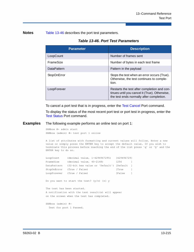
13–Command Reference
Test Port
59263-02 B 13-215
Notes Table 13-46 describes the port test parameters.
To cancel a port test that is in progress, enter the Test Cancel Port command.
To display the status of the most recent port test or port test in progress, enter the Test Status Port command.
Examples The following example performs an online test on port 1:
SANbox #> admin start
SANbox (admin) #> test port 1 online
A list of attributes with formatting and current values will follow. Enter a new value or simply press the ENTER key to accept the default value. If you wish to terminate this process before reaching the end of the list press 'q' or 'Q' and the ENTER key to do so.
LoopCount (decimal value, 1-4294967295) [429496729]
FrameSize (decimal value, 40-2148) [256 ]
DataPattern (32-bit hex value or 'Default') [Default ]
StopOnError (True / False) [True ]
LoopForever (True / False) [False ]
Do you want to start the test? (y/n) [n] y
The test has been started.
A notification with the test result(s) will appear
on the screen when the test has completed.
SANbox (admin) #>
Test for port 1 Passed.
Table 13-46. Port Test Parameters
Parameter Description
LoopCount Number of frames sent
FrameSize Number of bytes in each test frame
DataPattern Pattern in the payload
StopOnError Stops the test when an error occurs (True). Otherwise, the test continues to comple-tion.
LoopForever Restarts the test after completion and con-tinues until you cancel it (True). Otherwise, the test ends normally after completion.

13–Command Reference
Test Status
13-216 59263-02 B
Test StatusDisplays the status of a test in progress, or if there is no test in progress, the status of the last test that was executed.
Authority None
Syntax test statusport [port_number]switch
Keywords port [port_number]
Display test status for the port given by [port_number]. [port_number] can be 0–23.
switch
Display test status for the switch: Passed, Failed, NeverRun.
Examples The following is an example of the Test Status Port command:
SANbox (admin) #> test status port 1
Port Test Test Loop Test
Num Port Type Status Count Failures
---- -------- ---- ------ ----- --------
1 1 Offline Internal Passed 12 0

13–Command Reference
Test Status
59263-02 B 13-217
The following example of the Test Status Switch command:
SANbox (admin) #> test status switch
Test Test Test Loop Test
Level Type Status Count Failures
----- ---- ------ ----- --------
Switch Offline internal NeverRun 33 4
Port Test Test Loop Test
Num Type Status Count Failures
---- ---- ------ ----- --------
0 Offline internal StoppedOnError 12 2
1 Offline internal NeverRun 1 0
2 Offline internal Passed 4 0
3 Offline internal NeverRun 1 0
4 Offline internal NeverRun 1 0
5 Offline internal NeverRun 1 0
6 Offline internal NeverRun 1 0
7 Offline internal NeverRun 12 2
8 Unknown NeverRun 0 0
9 Unknown NeverRun 0 0
10 Unknown NeverRun 0 0
11 Unknown NeverRun 0 0
12 Unknown NeverRun 0 0
13 Unknown NeverRun 0 0
14 Unknown NeverRun 0 0
15 Unknown NeverRun 0 0
16 Unknown NeverRun 0 0
17 Unknown NeverRun 0 0
18 Unknown NeverRun 0 0
19 Unknown NeverRun 0 0
20 Unknown NeverRun 0 0
21 Unknown NeverRun 0 0
22 Unknown NeverRun 0 0
23 Unknown NeverRun 0 0

13–Command Reference
Test Switch
13-218 59263-02 B
Test SwitchTests all ports on the switch using a connectivity test, an offline test, or an online test.
Authority Admin session
Syntax test switchconnectivity [loopback_type]offline [loopback_type]online
Keywords connectivity [loopback_type]Performs a connectivity test of the type given by [loopback_type] on all switch ports. You must place the switch in the diagnostics state using the Set Switch State command before starting the test. [loopback_type] can be one of the following:
internal
Exercises all internal port and inter-port connections.
external
Exercises all internal port, transceiver, and inter-port connections. A transceiver with a loopback plug is required for all ports.
offline [loopback_type]
Performs an offline test of the type given by [loopback_type] on all switch ports. You must place the switch in the diagnostics state using the Set Switch State command before starting the test. [loopback_type] can have the following values:
internal
Exercises all internal port connections.
external
Exercises all port and transceiver connections. A transceiver with a loopback plug is required for all ports.
online
Exercises port-to-device connections for all ports that are online. The online test excludes TR_Ports. This test does not disrupt communication on the ports.

13–Command Reference
Test Switch
59263-02 B 13-219
Notes Table 13-47 describes the switch test parameters.
To cancel a switch test in progress, enter the Test Cancel Switch command.
To display the status of a recent switch test or switch test in progress, enter the Test Status Switch command.
Examples The following example performs an offline internal test on a switch:
SANbox #> admin start
SANbox (admin) #>set switch state diagnostics
SANbox (admin) #> test switch offline internal
A list of attributes with formatting and current values will follow. Enter a new value or simply press the ENTER key to accept the default value. If you wish to terminate this process before reaching the end of the list press 'q' or 'Q' and the ENTER key to do so.
LoopCount (decimal value, 1-4294967295) [100 ]
FrameSize (decimal value, 40-2148) [256 ]
DataPattern (32-bit hex value or 'Default') [Default]
StopOnError (True / False) [True ]
LoopForever (True / False) [False ]
Do you want to start the test? (y/n) [n] y
Table 13-47. Switch Test Parameters
Parameter Description
LoopCount Number of frames sent: 1–4294967295. The default is 100.
FrameSize Number of bytes in each test frame: 40–2148. The default is 256.
DataPattern 32-bit hexadecimal test value, or default, which defines random data
StopOnError Stops the test when an error occurs (True). Otherwise, the test continues to comple-tion.
LoopForever Restarts the test after completion and con-tinues until you cancel it (True). Otherwise, the test ends normally after completion.

13–Command Reference
Uptime
13-220 59263-02 B
UptimeDisplays the elapsed up time since the switch was last reset and the reset method. A hot reset or non-disruptive firmware activation does not reset the elapsed up time reported by this command.
Authority None
Syntax uptime
Examples The following is an example of the Uptime command:
SANbox #> uptime
Elapsed up time : 0 day(s), 2 hour(s), 28 min(s), 44 sec(s)
Reason last reset: NormalReset
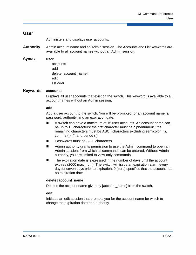
13–Command Reference
User
59263-02 B 13-221
UserAdministers and displays user accounts.
Authority Admin account name and an Admin session. The Accounts and List keywords are available to all account names without an Admin session.
Syntax useraccountsadddelete [account_name]editlist brief
Keywords accounts
Displays all user accounts that exist on the switch. This keyword is available to all account names without an Admin session.
add
Add a user account to the switch. You will be prompted for an account name, a password, authority, and an expiration date.
A switch can have a maximum of 15 user accounts. An account name can be up to 15 characters: the first character must be alphanumeric; the remaining characters must be ASCII characters excluding semicolon (;), comma (,), #, and period (.).
Passwords must be 8–20 characters.
Admin authority grants permission to use the Admin command to open an Admin session, from which all commands can be entered. Without Admin authority, you are limited to view-only commands.
The expiration date is expressed in the number of days until the account expires (2000 maximum). The switch will issue an expiration alarm every day for seven days prior to expiration. 0 (zero) specifies that the account has no expiration date.
delete [account_name]
Deletes the account name given by [account_name] from the switch.
edit
Initiates an edit session that prompts you for the account name for which to change the expiration date and authority.
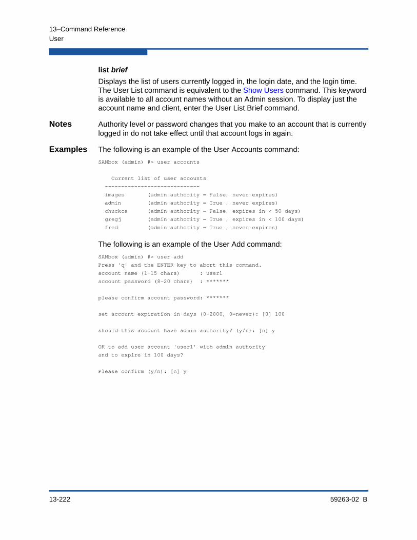
13–Command Reference
User
13-222 59263-02 B
list brief
Displays the list of users currently logged in, the login date, and the login time. The User List command is equivalent to the Show Users command. This keyword is available to all account names without an Admin session. To display just the account name and client, enter the User List Brief command.
Notes Authority level or password changes that you make to an account that is currently logged in do not take effect until that account logs in again.
Examples The following is an example of the User Accounts command:
SANbox (admin) #> user accounts
Current list of user accounts
-----------------------------
images (admin authority = False, never expires)
admin (admin authority = True , never expires)
chuckca (admin authority = False, expires in < 50 days)
gregj (admin authority = True , expires in < 100 days)
fred (admin authority = True , never expires)
The following is an example of the User Add command:
SANbox (admin) #> user add
Press 'q' and the ENTER key to abort this command.
account name (1-15 chars) : user1
account password (8-20 chars) : *******
please confirm account password: *******
set account expiration in days (0-2000, 0=never): [0] 100
should this account have admin authority? (y/n): [n] y
OK to add user account 'user1' with admin authority
and to expire in 100 days?
Please confirm (y/n): [n] y
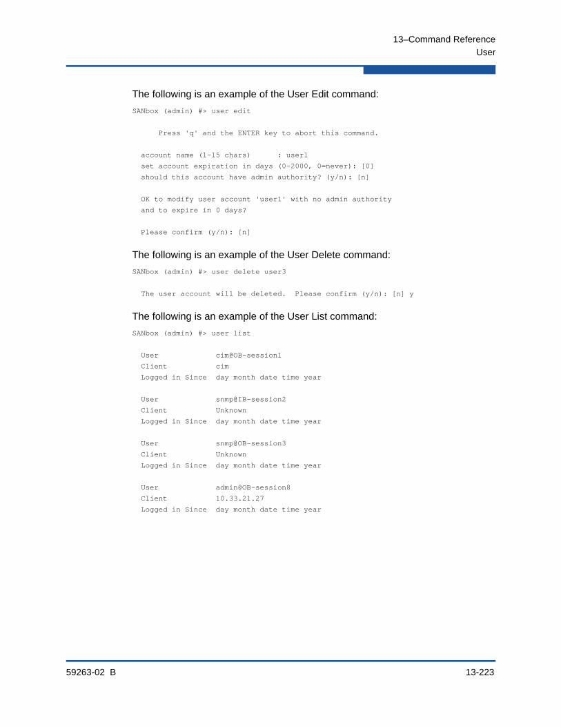
13–Command Reference
User
59263-02 B 13-223
The following is an example of the User Edit command:
SANbox (admin) #> user edit
Press 'q' and the ENTER key to abort this command.
account name (1-15 chars) : user1
set account expiration in days (0-2000, 0=never): [0]
should this account have admin authority? (y/n): [n]
OK to modify user account 'user1' with no admin authority
and to expire in 0 days?
Please confirm (y/n): [n]
The following is an example of the User Delete command:
SANbox (admin) #> user delete user3
The user account will be deleted. Please confirm (y/n): [n] y
The following is an example of the User List command:
SANbox (admin) #> user list
User cim@OB-session1
Client cim
Logged in Since day month date time year
User snmp@IB-session2
Client Unknown
Logged in Since day month date time year
User snmp@OB-session3
Client Unknown
Logged in Since day month date time year
User admin@OB-session8
Client 10.33.21.27
Logged in Since day month date time year

13–Command Reference
Whoami
13-224 59263-02 B
WhoamiDisplays the account name, session number, and switch domain ID for the Telnet session.
Authority None
Syntax whoami
Examples The following is an example of the Whoami command:
SANbox #> whoami
User name : admin@session2
Switch name : SANbox
Switch domain ID: 21 (0x15)

13–Command Reference
Zone
59263-02 B 13-225
ZoneManages zones and zone membership on a switch.
Authority Admin session and a Zoning Edit session. Refer to the “Zoning Edit” command on page 13-236 for information about starting a Zoning Edit session. The List, Members, and Zonesets keywords are available without an Admin session.
Syntax zoneadd [zone] [member_list]listmembers [zone]orphansremove [zone] [member_list]rename [zone_old] [zone_new]zonesets [zone]
Keywords add [zone] [member_list]
Specifies one or more ports/devices given by [members] to add to the zone named [zone]. Use a <space> to delimit aliases and ports/devices in [member_list]. A zone can have a maximum of 2000 members. [member_list] can have any of the following formats:
Domain ID and port number pair (Domain ID, Port Number). Domain IDs can be 1–239; port numbers can be 0–255.
6-character hexadecimal device Fibre Channel address (hex)
16-character hexadecimal worldwide port name (WWPN) with the format xx:xx:xx:xx:xx:xx:xx:xx.
Alias name
The application verifies that the [members] format is correct, but does not validate that such a member exists. You must enter the Zoning Save command afterwards to save your changes.
copy [zone_source] [zone_destination]
Creates a new zone named [zone_destination] and copies the membership into it from the zone given by [zone_source]. You must enter the Zoning Save command afterwards to save your changes.
create [zone]
Creates a zone with the name given by [zone]. An zone name must begin with a letter and be no longer than 64 characters. Valid characters are 0-9, A-Z, a-z, _, $, ^, and -. The zoning database supports a maximum of 2000 zones. You must enter the Zoning Save command afterwards to save your changes.

13–Command Reference
Zone
13-226 59263-02 B
delete [zone]
Deletes the specified zone given by [zone] from the zoning database. If the zone is a component of the active zone set, the zone will not be removed from the active zone set until the active zone set is deactivated. You must enter the Zoning Save command afterwards to save your changes.
list
Displays a list of all zones and the zone sets of which they are components. This keyword does not require an Admin session.
members [zone]
Displays all members of the zone given by [zone]. This keyword does not require an Admin session.
orphans
Displays a list of zones that are not members of any zone set.
remove [zone] [member_list]
Removes the ports/devices given by [member_list] from the zone given by [zone]. Use a <space> to delimit aliases and ports/devices in [member_list]. [member_list] can have any of the following formats:
Domain ID and port number pair (Domain ID, Port Number). Domain IDs can be 1–239; port numbers can be 0–255.
6-character hexadecimal device Fibre Channel address (hex)
16-character hexadecimal worldwide port name (WWPN) with the format xx:xx:xx:xx:xx:xx:xx:xx.
Alias name
You must enter the Zoning Save command afterwards to save your changes.
rename [zone_old] [zone_new]
Renames the zone given by [zone_old] to the zone given by [zone_new]. You must enter the Zoning Save command afterwards to save your changes.
zonesets [zone]
Displays all zone sets of which the zone given by [zone] is a component. This keyword does not require an Admin session.
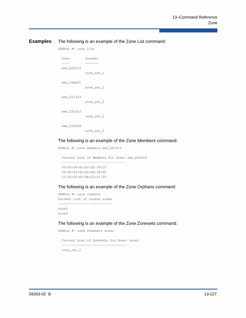
13–Command Reference
Zone
59263-02 B 13-227
Examples The following is an example of the Zone List command:
SANbox #> zone list
Zone ZoneSet
---- -------
wwn_b0241f
zone_set_1
wwn_23bd31
zone_set_1
wwn_221416
zone_set_2
wwn_2215c3
zone_set_2
wwn_0160ed
zone_set_3
The following is an example of the Zone Members command:
SANbox #> zone members wwn_b0241f
Current List of Members for Zone: wwn_b0241f
---------------------------------
50:06:04:82:bf:d2:18:c2
50:06:04:82:bf:d2:18:d2
21:00:00:e0:8b:02:41:2f
The following is an example of the Zone Orphans command:
SANbox #> zone orphans
Current list of orphan zones
----------------------------
zone3
zone4
The following is an example of the Zone Zonesets command:
SANbox #> zone zonesets zone1
Current List of ZoneSets for Zone: zone1
----------------------------------
zone_set_1

13–Command Reference
Zoneset
13-228 59263-02 B
ZonesetManages zone sets and component zones across the fabric.
Authority Admin session and a Zoning Edit session. Refer to the “Zoning Edit” command on page 13-236 for information about starting a Zoning Edit session. The Active, List, and Zones keywords are available without an Admin session. You must close the Zoning Edit session before using the Activate and Deactivate keywords.
Syntax zonesetactivate [zone_set]activeadd [zone_set] [zone_list]copy [zone_set_source] [zone_set_destination]create [zone_set]deactivatedelete [zone_set]listremove [zone_set] [zone_list]rename [zone_set_old] [zone_set_new]zones [zone_set]
Keywords activate [zone_set]
Activates the zone set given by [zone_set]. This keyword deactivates the active zone set. Close the Zoning Edit session before using this keyword.
active
Displays the name of the active zone set. This keyword does not require Admin session.
add [zone_set] [zone_list]
Adds a list of zones and aliases given by [zone_list] to the zone set given by [zone_set]. Use a <space> to delimit zone and alias names in [zone_list]. You must enter the Zoning Save command afterwards to save your changes.
copy [zone_set_source] [zone_set_destination]
Creates a new zone set named [zone_set_destination] and copies into it the zones from the zone set given by [zone_set_source]. You must enter the Zoning Save command afterwards to save your changes.
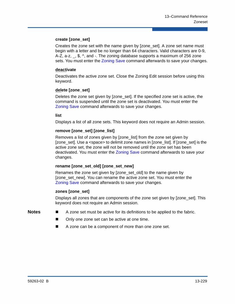
13–Command Reference
Zoneset
59263-02 B 13-229
create [zone_set]
Creates the zone set with the name given by [zone_set]. A zone set name must begin with a letter and be no longer than 64 characters. Valid characters are 0-9, A-Z, a-z, _, $, ^, and -. The zoning database supports a maximum of 256 zone sets. You must enter the Zoning Save command afterwards to save your changes.
deactivate
Deactivates the active zone set. Close the Zoning Edit session before using this keyword.
delete [zone_set]
Deletes the zone set given by [zone_set]. If the specified zone set is active, the command is suspended until the zone set is deactivated. You must enter the Zoning Save command afterwards to save your changes.
list
Displays a list of all zone sets. This keyword does not require an Admin session.
remove [zone_set] [zone_list]
Removes a list of zones given by [zone_list] from the zone set given by [zone_set]. Use a <space> to delimit zone names in [zone_list]. If [zone_set] is the active zone set, the zone will not be removed until the zone set has been deactivated. You must enter the Zoning Save command afterwards to save your changes.
rename [zone_set_old] [zone_set_new]
Renames the zone set given by [zone_set_old] to the name given by [zone_set_new]. You can rename the active zone set. You must enter the Zoning Save command afterwards to save your changes.
zones [zone_set]
Displays all zones that are components of the zone set given by [zone_set]. This keyword does not require an Admin session.
Notes A zone set must be active for its definitions to be applied to the fabric.
Only one zone set can be active at one time.
A zone can be a component of more than one zone set.
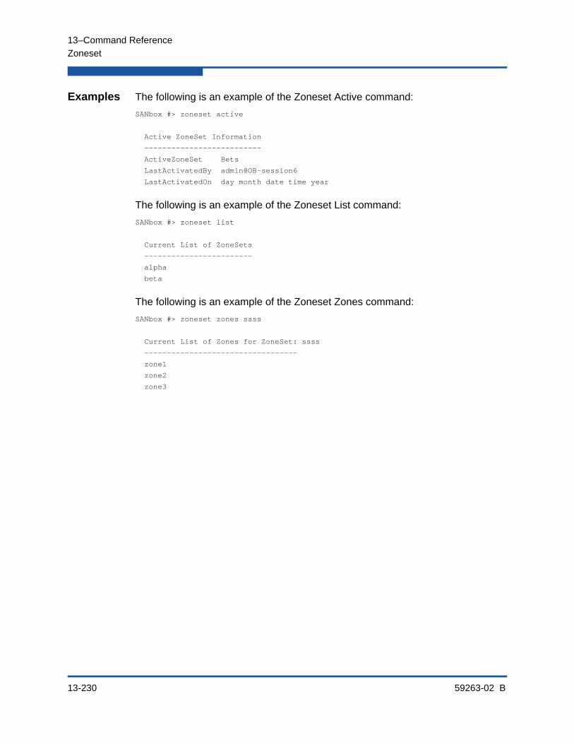
13–Command Reference
Zoneset
13-230 59263-02 B
Examples The following is an example of the Zoneset Active command:
SANbox #> zoneset active
Active ZoneSet Information
--------------------------
ActiveZoneSet Bets
LastActivatedBy admin@OB-session6
LastActivatedOn day month date time year
The following is an example of the Zoneset List command:
SANbox #> zoneset list
Current List of ZoneSets
------------------------
alpha
beta
The following is an example of the Zoneset Zones command:
SANbox #> zoneset zones ssss
Current List of Zones for ZoneSet: ssss
----------------------------------
zone1
zone2
zone3

13–Command Reference
Zoning Active
59263-02 B 13-231
Zoning ActiveDisplays information for the active zone set or saves the active zone set to the non-volatile zoning database.
Authority Admin session for the Capture keyword.
Syntax zoning activecapture
Keywords capture
Saves the active zone set to the non-volatile zoning data base.
Examples The following is an example of the Zoning Active command:
SANbox #> zoning active
Active (enforced) ZoneSet Information
ZoneSet Zone ZoneMember
--------------------------------
wwn
wwn_b0241f
50:06:04:82:bf:d2:18:c2
50:06:04:82:bf:d2:18:d2
21:00:00:e0:8b:02:41:2f
wwn_23bd31
50:06:04:82:bf:d2:18:c2
50:06:04:82:bf:d2:18:d2
10:00:00:00:c9:23:bd:31
wwn_221416
50:06:04:82:bf:d2:18:c2
50:06:04:82:bf:d2:18:d2
10:00:00:00:c9:22:14:16
wwn_2215c3
50:06:04:82:bf:d2:18:c2
50:06:04:82:bf:d2:18:d2
10:00:00:00:c9:22:15:c3
The following is an example of the Zoning Active Capture command:
SANbox (admin) #> zoning active capture
This command will overwrite the configured zoning database in NVRAM.
Please confirm (y/n): [n] y
The active zoning database has been saved.

13–Command Reference
Zoning Cancel
13-232 59263-02 B
Zoning CancelCloses the current Zoning Edit session. Any unsaved changes are lost.
Authority Admin session and a Zoning Edit session.
Syntax zoning cancel
Examples The following is an example of the Zoning Cancel command:
SANbox #> admin start
SANbox (admin) #> zoning edit
.
.
.
SANbox (admin-zoning) #> zoning cancel
Zoning edit mode will be canceled. Please confirm (y/n): [n] y

13–Command Reference
Zoning Clear
59263-02 B 13-233
Zoning ClearClears all inactive zone sets from the volatile edit copy of the zoning database. This keyword requires a zoning edit session. This keyword does not affect the non-volatile zoning database. However, if you enter the Zoning Clear command followed by the Zoning Save command, the non-volatile zoning database will be cleared from the switch.
Authority Admin session and a Zoning Edit session.
Syntax zoning clear
Examples The following is an example of the Zoning Clear command:
SANbox #> admin start
SANbox (admin) #> zoning edit
SANbox (admin-zoning) #> zoning clear
SANbox (admin-zoning) #> zoning save
NOTE:
The preferred method for clearing the zoning database from the switch is the Reset Zoning command.

13–Command Reference
Zoning Configured
13-234 59263-02 B
Zoning ConfiguredDisplays the contents of the non-volatile zoning database.
Authority None
Syntax zoning configured
Examples The following is an example of the Zoning Configured command:
SANbox #> zoning configured
Configured (saved in NVRAM) Zoning Information
ZoneSet Zone ZoneMember
------- ---- ----------
wwn
wwn_b0241f
50:06:04:82:bf:d2:18:c2
50:06:04:82:bf:d2:18:d2
wwn_23bd31
50:06:04:82:bf:d2:18:c2
50:06:04:82:bf:d2:18:d2
10:00:00:00:c9:23:bd:31
wwn_221416
50:06:04:82:bf:d2:18:c2
50:06:04:82:bf:d2:18:d2
10:00:00:00:c9:22:14:16
wwn_2215c3
50:06:04:82:bf:d2:18:c2
50:06:04:82:bf:d2:18:d2
10:00:00:00:c9:22:15:16
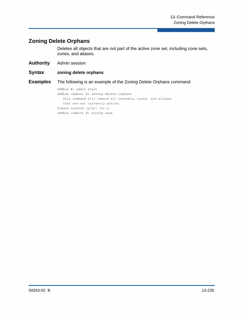
13–Command Reference
Zoning Delete Orphans
59263-02 B 13-235
Zoning Delete OrphansDeletes all objects that are not part of the active zone set, including zone sets, zones, and aliases.
Authority Admin session
Syntax zoning delete orphans
Examples The following is an example of the Zoning Delete Orphans command:
SANbox #> admin start
SANbox (admin) #> zoning delete orphans
This command will remove all zonesets, zones, and aliases
that are not currently active.
Please confirm (y/n): [n] y
SANbox (admin) #> zoning save
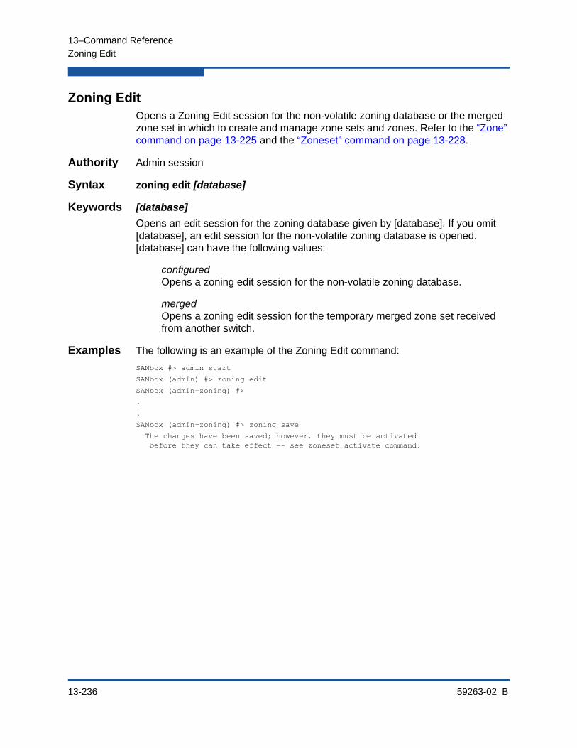
13–Command Reference
Zoning Edit
13-236 59263-02 B
Zoning EditOpens a Zoning Edit session for the non-volatile zoning database or the merged zone set in which to create and manage zone sets and zones. Refer to the “Zone” command on page 13-225 and the “Zoneset” command on page 13-228.
Authority Admin session
Syntax zoning edit [database]
Keywords [database]
Opens an edit session for the zoning database given by [database]. If you omit [database], an edit session for the non-volatile zoning database is opened. [database] can have the following values:
configuredOpens a zoning edit session for the non-volatile zoning database.
mergedOpens a zoning edit session for the temporary merged zone set received from another switch.
Examples The following is an example of the Zoning Edit command:
SANbox #> admin start
SANbox (admin) #> zoning edit
SANbox (admin-zoning) #>
.
.
SANbox (admin-zoning) #> zoning save
The changes have been saved; however, they must be activated before they can take effect -- see zoneset activate command.

13–Command Reference
Zoning Edited
59263-02 B 13-237
Zoning EditedDisplays the contents of the edited zoning database.
Authority Admin session and a Zoning Edit session
Syntax zoning edited
Examples The following is an example of the Zoning Edited command:
SANbox (admin-zoning) #> zoning edited
Edited (unsaved) Zoning Information
ZoneSet Zone ZoneMember
------- ---- ----------
ZS1
Z1
10:00:00:c0:dd:00:b9:f9
10:00:00:c0:dd:00:b9:fa

13–Command Reference
Zoning History
13-238 59263-02 B
Zoning HistoryDisplays a history of zoning modifications. This keyword does not require an Admin session. History information includes the following:
Time of the most recent zone set activation or deactivation and the user who performed it
Time of the most recent modifications to the zoning database and the user who made them.
Checksum for the zoning database
Authority None
Syntax zoning history
Examples The following is an example of the Zoning History command:
SANbox #> zoning history
Active Database Information
---------------------------
ZoneSetLastActivated/DeactivatedBy Remote
ZoneSetLastActivated/DeactivatedOn day mon date hh:mm:ss yyyy
Database Checksum 00000000
Inactive Database Information
-----------------------------
ConfigurationLastEditedBy admin@OB-session17
ConfigurationLastEditedOn day mon date hh:mm:ss yyyy
Database Checksum 00000000

13–Command Reference
Zoning Limits
59263-02 B 13-239
Zoning LimitsDisplays the limits and numbers of zone sets, zones, aliases, members per zone, members per alias, and total members in the zoning database.
Authority None
Syntax zoning limitsbrief
Keywords brief
Displays zoning limits for each category, the current number of objects, and the applicable zoning database (non-volatile or active). If you omit this keyword, the display includes a membership breakdown for each zone.
Notes The specific zoning database limits are described in Table 13-48.
Table 13-48. Zoning Database Limits
Limit Description
MaxZoneSets Maximum number of zone sets (256)
MaxZones Maximum number of zones (2000)
MaxAliases Maximum number of aliases (2500)
MaxTotalMembers Maximum number of zone and alias members (10000) that can be stored in the switch’s zoning database. Each instance of a zone member or alias member counts toward this maximum.
MaxZonesInZoneSets Maximum number of zones that are components of zone sets (2000), excluding those in the orphan zone set, that can be stored in the switch’s zoning database. Each instance of a zone in a zone set counts toward this maxi-mum.
MaxMembersPerZone Maximum number of members in a zone (2000)
MaxMembersPerAlias Maximum number of members in an alias (2000)

13–Command Reference
Zoning List
13-240 59263-02 B
Zoning ListLists all zoning definitions, including the applicable zoning database.
Authority None
Syntax zoning list
Examples The following is an example of the Zoning List command:
SANbox #> zoning list
Active (enforced) ZoneSet Information
ZoneSet Zone ZoneMember
--------------------------------
wwn
wwn_23bd31
50:06:04:82:bf:d2:18:c2
50:06:04:82:bf:d2:18:d2
10:00:00:00:c9:23:bd:31
wwn_221416
50:06:04:82:bf:d2:18:c2
50:06:04:82:bf:d2:18:d2
10:00:00:00:c9:22:14:16
wwn_2215c3
50:06:04:82:bf:d2:18:c2
50:06:04:82:bf:d2:18:d2
10:00:00:00:c9:22:15:c3
Configured (saved in NVRAM) Zoning Information
ZoneSet Zone ZoneMember
--------------------------------
wwn
wwn_23bd31
50:06:04:82:bf:d2:18:c2
50:06:04:82:bf:d2:18:d2
10:00:00:00:c9:23:bd:31
wwn_221416
50:06:04:82:bf:d2:18:c2
50:06:04:82:bf:d2:18:d2
10:00:00:00:c9:22:14:16
wwn_2215c3
50:06:04:82:bf:d2:18:c2
50:06:04:82:bf:d2:18:d2
10:00:00:00:c9:22:15:16

13–Command Reference
Zoning Merged
59263-02 B 13-241
Zoning MergedDisplays the contents of the merged zone set, or saves the merged zone set to the non-volatile zoning database.
Authority Admin session for the Capture keyword.
Syntax zoning mergedcapture
Keywords capture
Saves the merged zone set to the non-volatile zoning database. You must enter the Zoning Save command afterwards to save your changes. If you omit this keyword, this command displays the contents of the merged zone set.
Examples The following is an example of the Zoning Merged command:
SANbox #> zoning merged
*********************************************************************
To permanently save the merged database locally, execute the'zoning merged capture' command. To edit the merged databaseuse the ’zoning edit merged’ command. To remove the merged databaseuse the ’zoning restore’ command.
**********************************************************************
Merged (unsaved) Zoning Information
ZoneSet Zone ZoneMember
------- ---- ----------
ZS1
Z1
10:00:00:c0:dd:00:b9:f9
10:00:00:c0:dd:00:b9:fa
Z2
10:00:00:c0:dd:00:b9:fb
10:00:00:c0:dd:00:b9:fc
The following is an example of the Zoning Merged Capture command:
SANbox (admin) #> zoning merged capture
This command will overwrite the configured zoning database in NVRAM.
Please confirm (y/n): [n] y
The merged zoning database has been saved.
13–Command Reference
Zoning Restore
13-242 59263-02 B
Zoning RestoreRestores the volatile zoning database with the contents of the non-volatile zoning database. If the MergeAutoSave parameter is False (see Table 13-15), you can use this command to revert changes to the merged zone set that were propagated from another switch in the fabric through zone set activation or merging fabrics.
Authority Admin session
Syntax zoning restore

13–Command Reference
Zoning Save
59263-02 B 13-243
Zoning SaveSaves changes made during the current Zoning Edit session. The system informs you that the zone set must be activated to implement any changes.
Authority Admin session and a Zoning Edit session.
Syntax zoning save
Examples The following is an example of the Zoning Save command:
SANbox #> admin start
SANbox (admin) #> zoning edit
SANbox (admin-zoning) #>
.
.
SANbox (admin-zoning) #> zoning save
The changes have been saved; however, they must be activated before they can take effect -- see zoneset activate command.

13–Command Reference
Zoning Save
13-244 59263-02 B
59263-02 B Index-1
Index
Numerics20Gb stacking port license 4-29, 13-29
Aaccount name
admin 1-2display 13-221, 13-224factory 2-1maintenance mode 2-1
activationfirmware 4-19, 4-20security 8-8, 8-10switch configuration 4-11, 4-12zoning 6-11
active zone set 6-1, 6-3adapter 13-168Admin
account name 2-1, 13-1authority 1-3, 13-1session 1-3session timeout 13-145
Admin command 13-3Admin session 4-30administrative state
port 13-127switch 13-150
alarmconfiguration 5-14, 13-117configuration display 5-4, 13-162description 10-1, 13-124log 13-106, 13-154
aliasadd members 6-18, 13-4copy 6-18, 13-4create 6-17, 13-4delete 6-18, 13-5delete members 13-5display list 13-5display members 13-5information 6-7management 6-17remove 6-13remove ports/devices 6-18rename 6-18, 13-5
Alias command 13-4Add example 6-18Copy example 6-18Create example 6-17Delete example 6-18List example 6-7Members example 6-7Remove example 6-18Rename example 6-18
associationconcepts 3-7copy 3-20create 3-17delete 3-18information 3-9modify 3-19rename 3-20
authentication 8-1, 9-1, 13-34authority 2-1, 3-8, 3-10, 13-1authorization 8-1autosave
security database 8-6zoning database 6-9
User’s Guide Command Line Interface
5800V Series Stackable Fibre Channel Switch
Index-2 59263-02 B
Bbackup file 4-13beacon 4-16, 13-107binding
fabric 13-33, 13-37port 5-11, 13-114
Boot Protocol 13-143, 13-144broadcast 13-155
CCall Home
concepts 11-1database 11-2, 11-6, 11-7, 11-14edit session 13-1message queue 11-8, 11-13messages 11-3queue 11-3requirements 11-2reset 11-7service 11-2, 11-5, 13-137technical support interface 11-4
Callhome command 13-6Changeover example 11-13Clear example 11-14Edit example 11-6History example 11-7List example 11-7List Profile example 11-8Profile Test example 11-13Queue Clear example 11-13Queue Stats example 11-8
Capture command 13-10Add example 11-11Edit example 11-12Remove example 11-12
Central Processing Unit usage 4-4Cert_authority command 13-13certificate 3-8, 3-10, 7-2, 7-3, 13-21certificate authority 3-8, 3-10Certificate command 13-14
Challenge Handshake Authentication Protocol 13-34
CHAP - See Challenge Handshake Authentication Protocol
chassis status 13-155, 13-156Clone Config Port command 13-16command
entry 1-4examples 13-2listing 13-2notes 13-2reference 13-1rules and conventions 13-2syntax 13-2
command-line completion 1-4Config command 13-17
Activate example 4-11Backup example 4-13Copy example 4-11Delete example 4-11Edit example 4-11, 6-10List example 4-10Restore example 4-15
configurationactivate 4-11, 13-17backup 4-13, 13-17copy 4-11, 13-17delete 4-11, 13-18device security 8-1display 4-10edit 13-18edit session 13-1export 13-18import 13-18list 13-18modify 4-11reset 13-89restore 4-13, 4-15, 13-18save 13-19
configuration filedownload 1-8, 4-14upload 1-8
59263-02 B Index-3
User’s Guide Command Line Interface
5800V Series Stackable Fibre Channel Switch
connectionsecurity 7-1, 13-135, 13-136SSL 13-21
connectivity test 4-26CPU - See Central Processing UnitCRC - See Cyclic Redundancy CheckCreate command 13-21
Certificate example 7-3Support example 1-6
credit 13-165critical event 10-1Cyclic Redundancy Check errors 5-14
Ddata capture
add configuration 11-11delete configuration 11-12modify configuration 11-12
date 4-16, 4-18Date command 4-16, 13-24decode errors 5-14default
switch configuration 13-92zone 6-9
deviceaccess 6-1security configuration 8-1
digital certificate 3-8discard inactive 6-9discovery method 3-1display control 1-5DNS - See Domain Name Systemdomain ID
binding 13-33, 13-37display 13-164
Domain Name System 3-4donor port 13-165Dynamic Host Configuration Protocol 13-143,
13-144
Eelapsed time 4-4encryption 3-8Enterprise Fabric Suite 4-29, 13-29errors 5-14Ethernet
connection 11-2network information 3-1port configuration 3-2
eventmessage format 10-2output stream control 10-3remote logging 10-5severity level 10-1
event logclear 10-5configuration 10-1, 10-4configuration management 10-4display 10-2display configuration 10-5filter 10-3restore configuration 10-5
event loggingby component 13-121, 13-170by port 13-123, 13-172by severity level 13-172display 13-170remote 10-5restore defaults 13-124save settings 13-124settings 13-172severity level 13-123start and stop 10-2, 13-124
Exit command 13-25expiration date 2-1extended credit 13-165external test 5-15, 13-214, 13-218
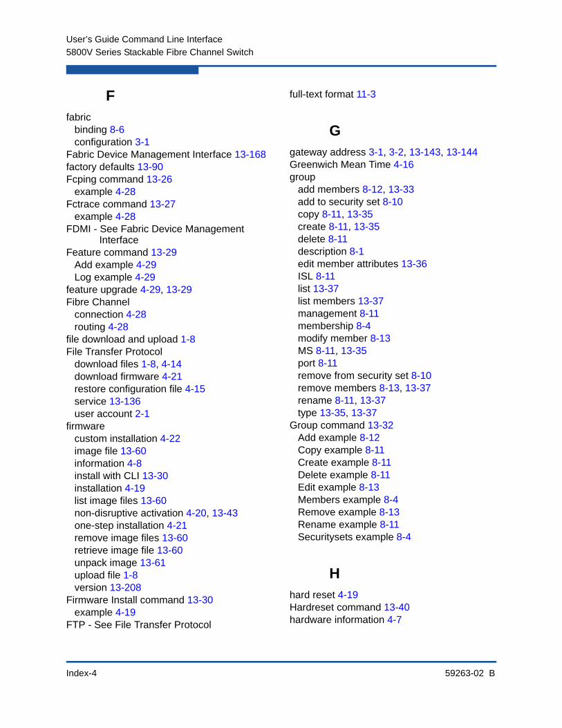
User’s Guide Command Line Interface
5800V Series Stackable Fibre Channel Switch
Index-4 59263-02 B
Ffabric
binding 8-6configuration 3-1
Fabric Device Management Interface 13-168factory defaults 13-90Fcping command 13-26
example 4-28Fctrace command 13-27
example 4-28FDMI - See Fabric Device Management
InterfaceFeature command 13-29
Add example 4-29Log example 4-29
feature upgrade 4-29, 13-29Fibre Channel
connection 4-28routing 4-28
file download and upload 1-8File Transfer Protocol
download files 1-8, 4-14download firmware 4-21restore configuration file 4-15service 13-136user account 2-1
firmwarecustom installation 4-22image file 13-60information 4-8install with CLI 13-30installation 4-19list image files 13-60non-disruptive activation 4-20, 13-43one-step installation 4-21remove image files 13-60retrieve image file 13-60unpack image 13-61upload file 1-8version 13-208
Firmware Install command 13-30example 4-19
FTP - See File Transfer Protocol
full-text format 11-3
Ggateway address 3-1, 3-2, 13-143, 13-144Greenwich Mean Time 4-16group
add members 8-12, 13-33add to security set 8-10copy 8-11, 13-35create 8-11, 13-35delete 8-11description 8-1edit member attributes 13-36ISL 8-11list 13-37list members 13-37management 8-11membership 8-4modify member 8-13MS 8-11, 13-35port 8-11remove from security set 8-10remove members 8-13, 13-37rename 8-11, 13-37type 13-35, 13-37
Group command 13-32Add example 8-12Copy example 8-11Create example 8-11Delete example 8-11Edit example 8-13Members example 8-4Remove example 8-13Rename example 8-11Securitysets example 8-4
Hhard reset 4-19Hardreset command 13-40hardware information 4-7
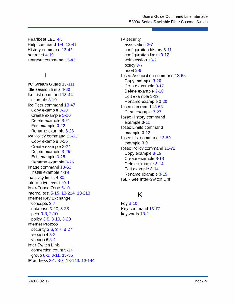
59263-02 B Index-5
User’s Guide Command Line Interface
5800V Series Stackable Fibre Channel Switch
Heartbeat LED 4-7Help command 1-4, 13-41History command 13-42hot reset 4-19Hotreset command 13-43
II/O Stream Guard 13-111idle session limits 4-30Ike List command 13-44
example 3-10Ike Peer command 13-47
Copy example 3-23Create example 3-20Delete example 3-21Edit example 3-22Rename example 3-23
Ike Policy command 13-53Copy example 3-26Create example 3-24Delete example 3-25Edit example 3-25Rename example 3-26
Image command 13-60Install example 4-19
inactivity limits 4-30informative event 10-1Inter-Fabric Zone 5-10internal test 5-15, 13-214, 13-218Internet Key Exchange
concepts 3-7database 3-20, 3-23peer 3-8, 3-10policy 3-8, 3-10, 3-23
Internet Protocolsecurity 3-6, 3-7, 3-27version 4 3-2version 6 3-4
Inter-Switch Linkconnection count 5-14group 8-1, 8-11, 13-35
IP address 3-1, 3-2, 13-143, 13-144
IP securityassociation 3-7configuration history 3-11configuration limits 3-12edit session 13-2policy 3-7reset 3-6
Ipsec Association command 13-65Copy example 3-20Create example 3-17Delete example 3-18Edit example 3-19Rename example 3-20
Ipsec command 13-63Clear example 3-27
Ipsec History commandexample 3-11
Ipsec Limits commandexample 3-12
Ipsec List command 13-69example 3-9
Ipsec Policy command 13-72Copy example 3-15Create example 3-13Delete example 3-14Edit example 3-14Rename example 3-15
ISL - See Inter-Switch Link
Kkey 3-10Key command 13-77keywords 13-2

User’s Guide Command Line Interface
5800V Series Stackable Fibre Channel Switch
Index-6 59263-02 B
Llicense key
20Gb stacking port 4-29, 13-29description 4-29display 4-29Enterprise Fabric Suite 13-29install 4-29, 13-29port activation 4-29
limits 13-239Link Control Frame 13-110link state database 13-174Lip command 13-79log
archive 13-121clear 13-121display 13-122, 13-171event 13-121, 13-170local 13-144POST 13-191remote 13-144
log filecreate and download 10-6download 1-8upload 1-8
logged in users 13-207login
errors 5-14limit 1-3session 4-30
Logout command 13-80logout errors 5-14loop port initialization 13-79loss-of-signal errors 5-14
Mmaintenance mode 2-1Management Server
group 8-1, 8-11, 13-35service 13-137
manufacturer information 13-193mask address 13-143, 13-144
MD5 authentication 13-34memory activity 13-178message
format 11-3queue 11-8, 11-13
MS - See Management ServerMulti-Frame Sequence bundling 13-110
Nname server information 4-2, 13-179network
configuration 3-1configuration reset 13-91discovery 3-1, 3-2, 13-143, 13-144enable 13-143gateway address 13-143, 13-144interfaces 13-169IP address 13-143, 13-144mask 13-143, 13-144
Network Time Protocolclient 13-145date and time 4-18description 4-16interaction with Date command 13-24server address 13-145service 13-136
non-disruptive activation 13-43NPIV - See N-Port ID VirtualizationN-Port ID Virtualization 5-8, 5-9NTP - See Network Time Protocol
Ooffline test
port 5-16switch 4-25
online testport 5-15switch 4-24
operational information 4-3orphan zones 6-6

59263-02 B Index-7
User’s Guide Command Line Interface
5800V Series Stackable Fibre Channel Switch
output stream control 10-3
Ppage break 1-5Passwd command 2-4, 13-81password
change 13-81default 1-2File Transfer Protocol 1-8switch 13-81user account 2-4
peercopy 3-23create 3-20delete 3-21description 3-8information 3-10modify 3-22rename 3-23
performance tuning 13-110Ping command 13-82
example 3-5PKI - See Public Key Infrastructurepolicy (IKE)
copy 3-26create 3-24delete 3-25description 3-8information 3-10modify 3-25rename 3-26
policy (IP)copy 3-15create 3-13delete 3-14description 3-7information 3-9modify 3-14rename 3-15
portactivation 4-29, 13-29administrative state 13-127binding 5-11, 13-114, 13-160configuration 5-1, 13-108configuration display 13-157configuration parameters 5-2counters 13-126external test 13-214, 13-218group 8-1, 8-11, 13-35information 5-1initialize 13-90internal test 13-214, 13-218modify operating characteristics 5-7online test 13-214, 13-218operational information 5-3, 13-185performance 5-5, 13-181, 13-182performance tuning 13-110reset 5-13speed 13-126testing 5-15threshold alarms 5-4, 5-14
POST - See Power-On Self TestPower-On Self Test log 13-191preference routing 13-110process identifier 4-4processing time 4-4profile
copy 11-11, 13-83create 11-9, 13-83delete 11-9, 13-84edit 13-84modify 11-10rename 11-11, 13-84Tech_Support_Center 11-4, 11-14test 11-13
Profile command 13-83Copy example 11-11Create example 11-9Delete example 11-9Edit example 11-10Rename example 11-11
Ps command 4-4, 13-87
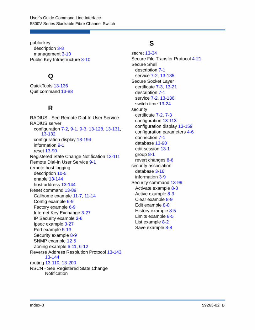
User’s Guide Command Line Interface
5800V Series Stackable Fibre Channel Switch
Index-8 59263-02 B
public keydescription 3-8management 3-10
Public Key Infrastructure 3-10
QQuickTools 13-136Quit command 13-88
RRADIUS - See Remote Dial-In User ServiceRADIUS server
configuration 7-2, 9-1, 9-3, 13-128, 13-131, 13-132
configuration display 13-194information 9-1reset 13-90
Registered State Change Notification 13-111Remote Dial-In User Service 9-1remote host logging
description 10-5enable 13-144host address 13-144
Reset command 13-89Callhome example 11-7, 11-14Config example 6-9Factory example 6-9Internet Key Exchange 3-27IP Security example 3-6Ipsec example 3-27Port example 5-13Security example 8-9SNMP example 12-5Zoning example 6-11, 6-12
Reverse Address Resolution Protocol 13-143, 13-144
routing 13-110, 13-200RSCN - See Registered State Change
Notification
Ssecret 13-34Secure File Transfer Protocol 4-21Secure Shell
description 7-1service 7-2, 13-135
Secure Socket Layercertificate 7-3, 13-21description 7-1service 7-2, 13-136switch time 13-24
securitycertificate 7-2, 7-3configuration 13-113configuration display 13-159configuration parameters 4-6connection 7-1database 13-90edit session 13-1group 8-1revert changes 8-6
security associationdatabase 3-16information 3-9
Security command 13-99Activate example 8-8Active example 8-3Clear example 8-9Edit example 8-8History example 8-5Limits example 8-5List example 8-2Save example 8-8

59263-02 B Index-9
User’s Guide Command Line Interface
5800V Series Stackable Fibre Channel Switch
security databaseautosave 8-6clear 13-99configuration 8-6description 8-1display 13-100display history 13-100information 8-1limits 8-5, 13-100modification history 8-5modify 8-8reset 8-9restore 8-6
security edit sessioncancel 13-99initiate 13-100revert changes 13-100save changes 13-100
security policydatabase 3-12information 3-9
security setactivate 8-10, 13-103active 8-3add group 8-10add member group 13-103configured 8-2copy 8-10, 13-103create 8-9, 13-104deactivate 8-10, 13-104delete 8-9, 13-104delete member group 13-104description 8-1display 13-104display active 13-99, 13-103display members 13-104information 8-2management 8-9membership 8-4remove groups 8-10rename 8-10, 13-104
Securityset command 13-103Activate example 8-10Active example 8-3Add example 8-10Copy example 8-10Create example 8-9Deactivate example 8-10Delete example 8-9Group example 8-4List example 8-2Remove example 8-10Rename example 8-10
servicesdisplay 4-9, 7-3managing 4-9SNMP 12-2
Set Beacon command 4-16Set Config Port command 13-108
example 5-7Set Config Security command 13-113
example 8-7Set Config Security Port command 13-114
example 5-12Set Config Switch command 13-115
example 4-12Set Config Threshold command 13-117
example 5-14Set Config Zoning command 13-119
example 6-9Set Log command 13-121
Archive example 10-6Clear example 10-5Display example 10-3example 10-4Restore example 10-5Start example 10-2Stop example 10-2
Set Pagebreak command 13-125example 1-5
Set Port command 13-126Set Setup Callhome command 13-128
example 11-5Set Setup command
SNMP example 12-4
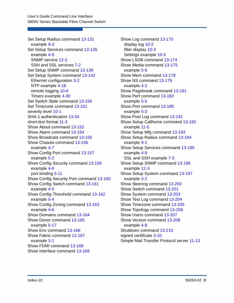
User’s Guide Command Line Interface
5800V Series Stackable Fibre Channel Switch
Index-10 59263-02 B
Set Setup Radius command 13-131example 9-3
Set Setup Services command 13-135example 4-9SNMP service 12-2SSH and SSL services 7-2
Set Setup SNMP command 13-138Set Setup System command 13-142
Ethernet configuration 3-2NTP example 4-18remote logging 10-6Timers example 4-30
Set Switch State command 13-150Set Timezone command 13-151severity level 10-1SHA-1 authentication 13-34short-text format 11-3Show About command 13-152Show Alarm command 13-154Show Broadcast command 13-155Show Chassis command 13-156
example 4-7Show Config Port command 13-157
example 5-2Show Config Security command 13-159
example 4-6port binding 5-11
Show Config Security Port command 13-160Show Config Switch command 13-161
example 4-5Show Config Threshold command 13-162
example 5-4Show Config Zoning command 13-163
example 4-6Show Domains command 13-164Show Donor command 13-165
example 5-17Show Env command 13-166Show Fabric command 13-167
example 3-1Show FDMI command 13-168Show Interface command 13-169
Show Log command 13-170display log 10-2filter display 10-3Settings example 10-5
Show LSDB command 13-174Show Media command 13-175
example 5-6Show Mem command 13-178Show NS command 13-179
example 4-2Show Pagebreak command 13-181Show Perf command 13-182
example 5-5Show Port command 13-185
example 5-3Show Post Log command 13-191Show Setup Callhome command 13-192
example 11-5Show Setup Mfg command 13-193Show Setup Radius command 13-194
example 9-1Show Setup Services command 13-195
example 4-9SSL and SSH example 7-3
Show Setup SNMP command 13-196example 12-3
Show Setup System command 13-197example 3-2
Show Steering command 13-200Show Switch command 13-201Show System command 13-203Show Test Log command 13-204Show Timezone command 13-205Show Topology command 13-206Show Users command 13-207Show Version command 13-208
example 4-8Shutdown command 13-210signed certificate 3-10Simple Mail Transfer Protocol server 11-13

59263-02 B Index-11
User’s Guide Command Line Interface
5800V Series Stackable Fibre Channel Switch
Simple Network Management Protocolconfiguration 12-1, 13-138configuration display 13-196information 12-3modify configuration 12-4reset 13-90reset configuration 12-5service 12-2, 13-136user account 12-7version 3 12-4, 12-6, 13-211
SMI-S - See Storage Management Initiative-Specification
Snmpv3user command 13-211soft
reset 4-19zone 6-1
SSH - See Secure ShellSSL - See Secure Socket LayerStorage Management Initiative-Specification
13-136subnet mask 3-1support file
create 1-6, 13-21download 1-7, 1-8upload 1-8
switchadministrative state 13-150configuration 4-1, 4-10, 13-115configuration defaults 13-92configuration display 13-161configuration parameters 4-5, 4-12date and time 7-3hard reset 13-40information 4-1log 13-144login 1-2management service 13-135manufacturer information 13-193operational information 4-3, 13-201paging 4-16reset 4-5, 4-19, 13-220reset without POST 13-91services 4-9, 13-90, 13-135, 13-195user accounts 2-1
syntax 13-2system configuration
change 13-142display 13-197
system process information 4-4
Ttechnical support 1-6Telnet
connection security 7-2login 1-2service 13-135session timeout 13-145
testcancel 4-27, 5-17connectivity 4-26offline 4-25, 5-16online 4-24, 5-15status 4-26, 5-17
Test Cancel command 13-213Test command
example 5-15test log file 13-204Test Port command 13-214
example 5-15Test Status command 13-216Test Switch command 13-218TFTP - See Trivial File Transfer Protocoltime
between resets 4-5set and display 4-16, 13-24set with NTP 4-18zone 4-16, 13-151, 13-205
timeoutAdmin session 13-145admin session 3-2inactivity 3-2Telnet session 13-145
topology 13-206TR_Port 5-8transceiver information 5-6transparent routing 5-8

User’s Guide Command Line Interface
5800V Series Stackable Fibre Channel Switch
Index-12 59263-02 B
Trivial File Transfer Protocol 4-21, 13-60Tsc1 text format 11-3
UUniversal Time 4-16upgrade 4-29, 13-29Uptime command 13-220
example 4-5user account
add 13-221configuration 2-1create 2-3delete 13-221display 13-221edit 13-221information 2-2list 13-222logged in 13-207modify 2-4password 2-4
user administration 13-221User command 13-221
Accounts example 2-2Add example 2-3Delete example 2-4Edit example 2-4List example 2-2
VVirtual Interface preference routing 13-110
Wwarning 10-1web applet
service 13-136Whoami command 13-224workstation
date and time 7-3settings 1-2
Zzone
add member port 13-225add to zone set 6-14, 6-17copy 6-16, 13-225create 6-16, 13-225definition 6-1delete 6-16, 13-226delete member port 13-226list 13-226list members 13-226management 6-15membership 6-6orphan 13-226orphans 6-6remove 6-13remove from zone set 6-15remove ports/devices 6-17rename 6-16, 13-226
Zone command 13-225Add example 6-17Copy example 6-16Create example 6-16Delete example 6-16Members example 6-6Remove example 6-17Rename example 6-16Zonesets example 6-6
59263-02 B Index-13
User’s Guide Command Line Interface
5800V Series Stackable Fibre Channel Switch
zone setactivate 6-15, 13-228active 6-1, 6-3, 6-12, 13-231add member zone 13-228add zones 6-14configured 6-2copy 6-14, 13-228create 6-13, 13-229deactivate 6-15, 13-91, 13-229definition 6-1delete 6-14, 13-229delete member zone 13-229display 13-229display active 13-228display members 13-229display zones 13-226information 6-2management 6-13membership 6-5merged 6-4, 6-12remove 6-13remove zones 6-15rename 6-14, 13-229
Zoneset command 13-228Activate example 6-15Active example 6-4Add example 6-14Copy example 6-14Create example 6-13Deactivate example 6-15Delete example 6-14List example 6-2Merged example 6-4Remove example 6-15Rename example 6-14Zones example 6-5
zoningconfiguration 6-1, 13-119configuration display 13-163configuration parameters 4-6database 13-91edit session 13-1hardware enforced 6-1information 6-2limits 13-239list definitions 13-240merged zone set 6-9modification history 6-7modify 6-10reset 6-11restore 6-9revert changes 13-242save edits 13-243
Zoning Active command 13-231Capture example 6-12example 6-3
Zoning Cancel command 13-232Zoning Clear command 13-233
example 6-12Zoning command
Merged Capture example 6-12Zoning Configured command 13-234zoning database
configuration 6-9limits 6-8modify 6-11reset 6-12
Zoning Delete commandexample 6-13
Zoning Delete Orphans command 13-235Zoning Edit command 13-236
example 6-11Zoning Edited command 13-237Zoning History command 13-238
example 6-7Zoning Limits command 13-239
example 6-8Zoning List command 13-240
example 6-2

User’s Guide Command Line Interface
5800V Series Stackable Fibre Channel Switch
Index-14 59263-02 B
Zoning Merged command 13-241Capture example 6-12
Zoning Restore command 13-242Zoning Save command 13-243


Corporate Headquarters QLogic Corporation 26650 Aliso Viejo Parkway Aliso Viejo, CA 92656 949.389.6000 www.qlogic.com
International Offices UK | Ireland | Germany | France | India | Japan | China | Hong Kong | Singapore | Taiwan
© 2011 QLogic Corporation. Specifications are subject to change without notice. All rights reserved worldwide. QLogic, the QLogic logo, Enterprise Fabric Suite, and QuickTools are trademarks or registered trademarks of QLogic Corporation. Microsoft, Windows NT, and Windows 2000/2003, and Internet Explorer are registered trademarks of Microsoft Corporation. Brocade is a registered trademark of Brocade Communications Systems, Inc. Cisco is a registered trademark of Cisco Systems, Inc. All other brand and product names are trademarks or registered trademarks of their respective owners. Information supplied by QLogic Corporation is believed to be accurate and reliable. QLogic Corporation assumes no responsibility for any errors in this brochure. QLogic Corporation reserves the right, without notice, to make changes in product design or specifications.