57892883 geometric-modeling
29
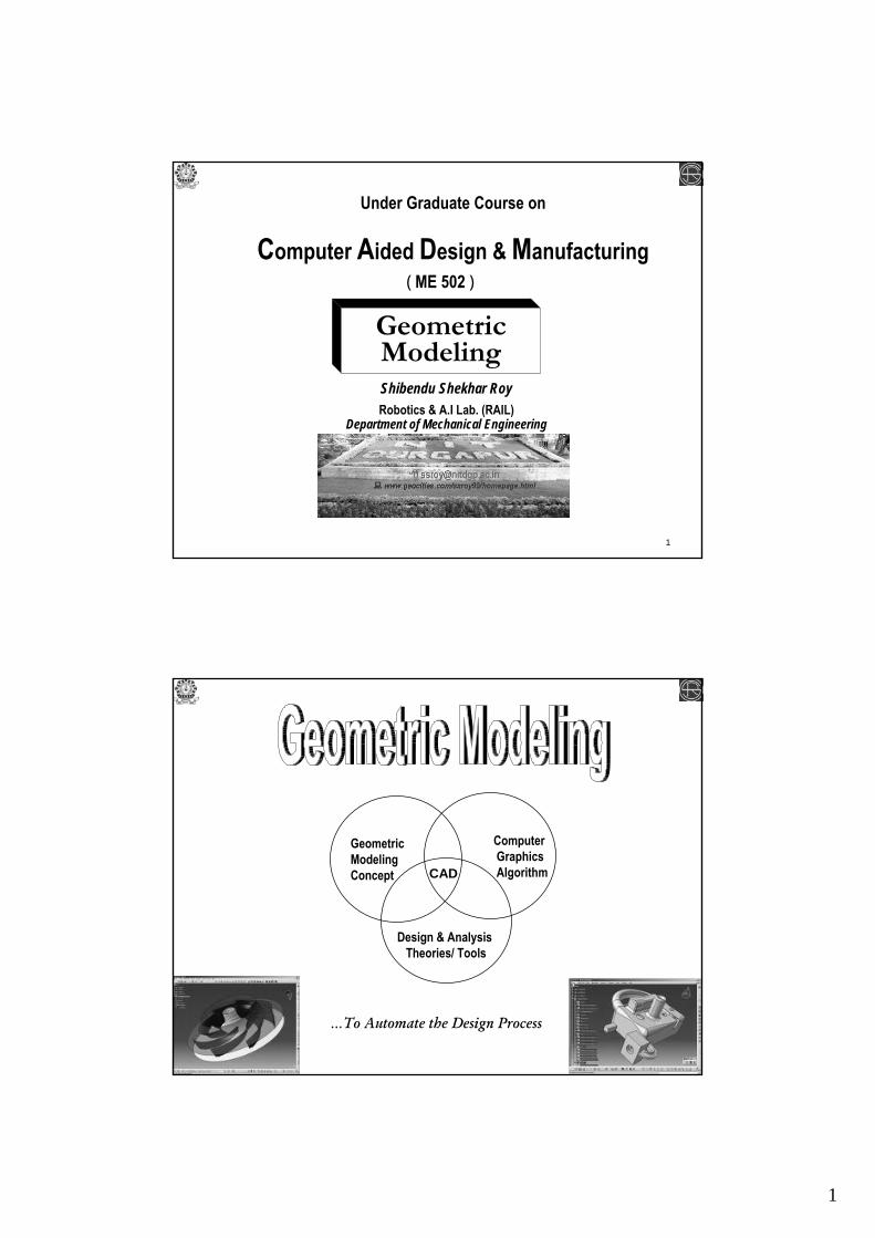
1 1 Under Graduate Course on Computer Aided Design & Manufacturing Geometric Modeling Shibendu Shekhar Roy Robotics & A.I Lab. (RAIL) Department of Mechanical Engineering ( ME 502 ) 2 Geometric Modeling Concept Design & Analysis Theories/ Tools Computer Graphics Algorithm CAD …To Automate the Design Process
-
Upload
manojg1990 -
Category
Documents
-
view
59 -
download
5
Transcript of 57892883 geometric-modeling
1
1
Under Graduate Course on
Computer Aided Design & Manufacturing
Geometric ModelingShibendu Shekhar RoyRobotics & A.I Lab. (RAIL)
Department of Mechanical Engineering
( ME 502 )
2
Geometric ModelingConcept
Design & Analysis Theories/ Tools
Computer GraphicsAlgorithmCAD
…To Automate the Design Process
2
3
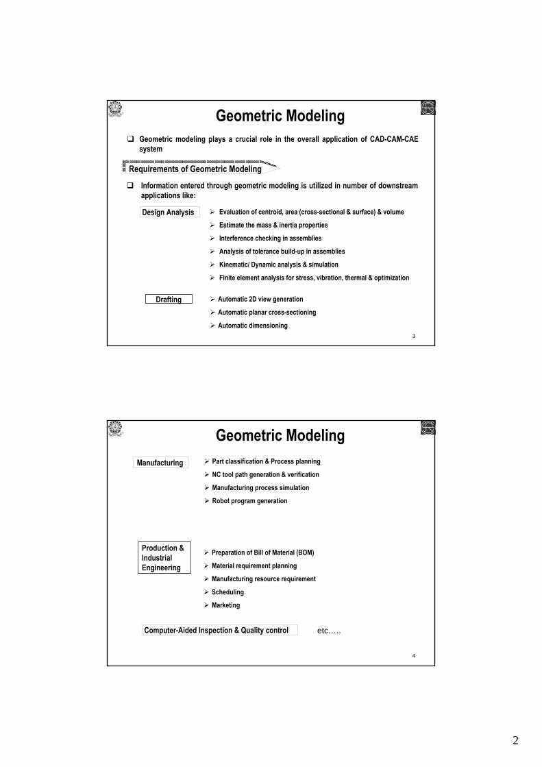
Geometric ModelingGeometric modeling plays a crucial role in the overall application of CAD-CAM-CAE system
Information entered through geometric modeling is utilized in number of downstream applications like:
Design Analysis
Drafting
Evaluation of centroid, area (cross-sectional & surface) & volume
Estimate the mass & inertia properties
Interference checking in assemblies
Analysis of tolerance build-up in assemblies
Kinematic/ Dynamic analysis & simulation
Finite element analysis for stress, vibration, thermal & optimization
Automatic 2D view generation
Automatic planar cross-sectioning
Automatic dimensioning
Requirements of Geometric Modeling
4
Geometric Modeling
Production & Industrial Engineering
Manufacturing Part classification & Process planning
NC tool path generation & verification
Manufacturing process simulation
Robot program generation
Preparation of Bill of Material (BOM)
Material requirement planning
Manufacturing resource requirement
Scheduling
Marketing
Computer-Aided Inspection & Quality control etc…..

3
5
Geometric ModelingHence, It is important that the geometric model generated should be as clear & comprehensive as possible so that the other modules of CAD-CAM-CAE system are able to use this information in the most optimal way.
Geometric model
Three Dimensional (3-D)
Two Dimensional (2-D)
Solid Modeling
Surface Modeling
Wireframe Modeling
6
Geometric Model
Three Dimensional (3-D)
Two Dimensional (2-D)
Utility of 2-D model lies in many of the low end drafting packages which is required for preparing manufacturing drawings
Their utility is limited because of their inherent difficulty in representing complex objects.
The 3-D geometric modeling has the ability to provide all the information required for CAD-CAM-CAE applications
A 3-D geometric model should be an unambiguous representation of an object.
A 3-D model should be complete to all engineering function from documentation (drafting & shading) to engineering analysis to manufacturing.
Basic Requirement

4
7
In this method the complete object is represented by number of lines, points, arcs & curves and their connectivity relationships
Wireframe Modeling
Disadvantages
The construction of a wireframe model is simple It does not require much computer time & memory. It can be used for simple NC tool path generation
Advantages
It can not be used for calculation of mass, inertia propertiesThe interpretation of wireframe models having many edges is very difficult
8
The surface model is constructed essentially from surfaces such a s planes, rotated curved surfaces & even very complex synthetic surfaces.
Surface creation on existing CAD system usually requires wireframe entities as a start
Surface & wireframe form the core of all existing CAD system
Surface Modeling
Disadvantages
Surface model of an object is a relatively more complete & less ambiguous representation than its wireframe model This method is very much useful for specific non-analytical surfaces ( free-form surface/ sculptured surfaces) such as those used for modeling automobile & airplane bodies & turbine blades etc. From an application point of view, surface models can be utilized in Finite Element Modeling, NC tool path generation, sectioning & interference detections.
Advantages
The calculation of mass & inertia properties would be difficult
5
9
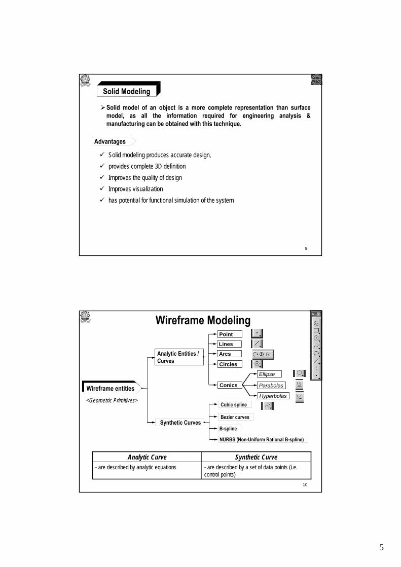
Solid model of an object is a more complete representation than surface model, as all the information required for engineering analysis & manufacturing can be obtained with this technique.
Solid modeling produces accurate design,provides complete 3D definitionImproves the quality of designImproves visualizationhas potential for functional simulation of the system
Advantages
Solid Modeling
10
Wireframe Modeling
Wireframe entities
Synthetic Curves
Analytic Entities / Curves
Point
Lines
Arcs
Ellipse
Circles
Conics Parabolas
Hyperbolas
NURBS (Non-Uniform Rational B-spline)
Bezier curves
Cubic spline
B-spline
- are described by a set of data points (i.e. control points)
- are described by analytic equationsSynthetic CurveAnalytic Curve
<Geometric Primitives>

6
11
Synthetic Curve
Analytic Curve
are defined as those that can be described by analytic equations such as lines, circle, conics etc.
provide very compact forms to represent shapes & simplify the computation of related properties such as areas & volume.
Analytic curves are usually not sufficient to meet today’s geometric design requirements of complex mechanical parts like automobile bodies, aeroplane wings, propeller blades, bottles etc.
That require synthetic curves & surfaces (free-form surfaces)
are defined as those that can be described by a set of data points (i.e. control points) such as Splines, Bezier curve etc.
Synthetic curves provide designers with greater flexibility & control of a curve shape by changing the positions of the one or more data points or control points.
12
Synthetic Curve
The need for synthetic curves in design arises on two occasions:
i) when a curve is represented by a collection of measured data points (in case of Reverse Engineering) [graphical visualization of experimental data]
ii) when an existing curve must change to meet new design requirements.
Synthetic Curve Construction Techniques :
Interpolation technique Curve passes through the data points
Curve do not passes through the data pointsApproximation technique
Mathematically, synthetic curves represent a Curve-fitting problem to construct a smooth curve

7
13
- Produce curves that do not pass through the given data points. Instead, these points are used to control the shape of the resulting curves
- Curve resulting from this technique pass through the given data points; curve itself is called Interpolant
-Ex. : Bezier Curve- Ex. : Cubic Spline
Approximation TechniqueInterpolation Technique
Most often, approximation techniques are preferred over interpolation techniques in free-form curve design due to the added flexibility & the additional intuitive feel provided by approximate technique.
P0
P1 P2
P3
P0
P1
P2
P3
P0
P12P5
P4
P3
P2
P1 P8
P7
P6
P11
P10
P9
14
Mathematical Representation of Curves
Curve can be described mathematically by
Parametric equation
Non-parametric equation
Explicit form
Implicit form
Non-parametric equation : Explicit form
If the co-ordinates ‘y’ & ‘z’ of a point on the curve are expressed as two separate functions of the third co-ordinate ‘x’ <independent variable>. This curve representation is known as Non-parametric Explicit form.
Non-parametric Explicit form of a general 3-D curve
P (x,y,z)
P
Position vector of a point ‘P’ on the curve = P = [x y z]T= [x f(x) g(x) ]T
X
Y
Z
8
15
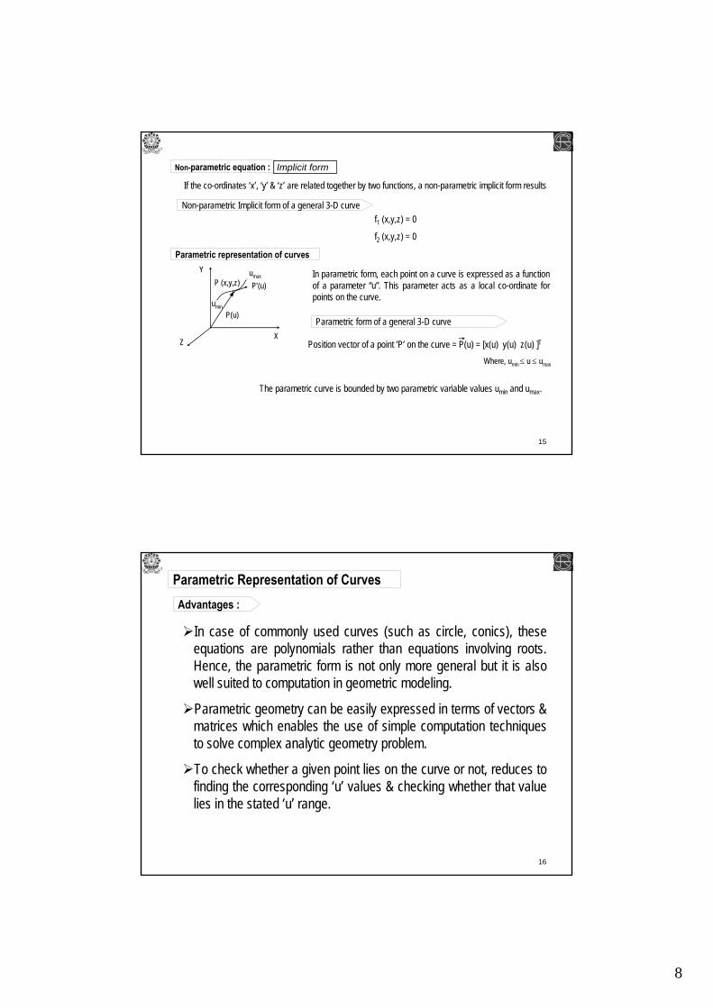
Non-parametric equation : Implicit form
If the co-ordinates ‘x’, ‘y’ & ‘z’ are related together by two functions, a non-parametric implicit form results
Non-parametric Implicit form of a general 3-D curvef1 (x,y,z) = 0
f2 (x,y,z) = 0
Parametric representation of curves
P (x,y,z)
P(u)
X
Y
Z
In parametric form, each point on a curve is expressed as a function of a parameter “u”. This parameter acts as a local co-ordinate for points on the curve.
P’(u)umax
umin
Parametric form of a general 3-D curve
Position vector of a point ‘P’ on the curve = P(u) = [x(u) y(u) z(u) ]T
The parametric curve is bounded by two parametric variable values umin and umax.
Where, umin≤ u ≤ umax
16
Advantages :
Parametric Representation of Curves
In case of commonly used curves (such as circle, conics), these equations are polynomials rather than equations involving roots.Hence, the parametric form is not only more general but it is also well suited to computation in geometric modeling.
Parametric geometry can be easily expressed in terms of vectors & matrices which enables the use of simple computation techniques to solve complex analytic geometry problem.
To check whether a given point lies on the curve or not, reduces to finding the corresponding ‘u’ values & checking whether that value lies in the stated ‘u’ range.
9
17
Blending is used to construct composite curve. Blending of two curves implies the joining of two curves subjected to the satisfaction of continuity condition.
Various Continuity requirements can be specified at data points to impose various degrees of smoothness of the resulting curve.
The order of continuity becomes important when a complex curve is modeled by several curve segments pieced together end-to-end.
Order of Continuity
18
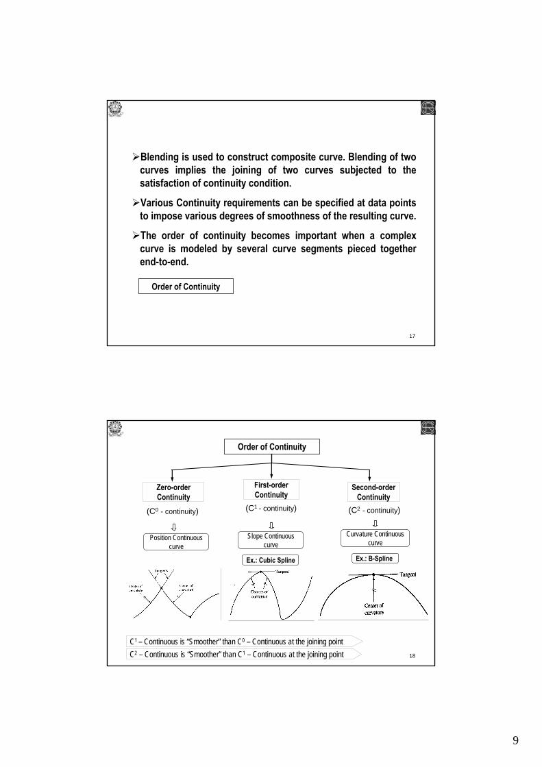
Order of Continuity
Zero-order Continuity
First-order Continuity
Second-order Continuity
(C0 - continuity) (C1 - continuity) (C2 - continuity)
Position Continuous curve
Slope Continuous curve
Curvature Continuous curve
C1 – Continuous is “Smoother” than C0 – Continuous at the joining pointC2 – Continuous is “Smoother” than C1 – Continuous at the joining point
Ex.: Cubic Spline Ex.: B-Spline

10
19
Cubic Splines
Synthetic Curves
Splines are used to interpolate to given data i.e. based on Interpolation technique.
A spline is a piecewise parametric representation of the geometry of a curve with a specified order of continuity.
Cubic splines use a parametric equations of 3rd degree with the first order continuity maintained at the intersection point of the curve.
Name from the traditional drafting tool called “Splines” or “French Curves”
P0
P0.8P1
P.0.4
20
Cubic Splines
Vector form3
ii
i 0P(u) u
=
= ∑C
2 30 1 2 3P(u) u u u= + + +C C C C
TP(u) = U C
2
3
1uuu
⎡ ⎤⎢ ⎥⎢ ⎥=⎢ ⎥⎢ ⎥⎣ ⎦
U
Matrix form 0
1
2
3
⎡ ⎤⎢ ⎥⎢ ⎥=⎢ ⎥⎢ ⎥⎣ ⎦
CC
CCC
The parametric equation of a cubic spline segment is given by
Cubic splines use cubic polynomial.
0 u 1≤ ≤
Where, C= Coefficients Vector
u= parameterCi= Polynomial Coefficients
Cubic polynomial has four coefficients & thus requires four conditions to evaluate .
- Uses two data points at its ends & two tangent vectors at these points
- Uses four data points
Hermite Cubic SplineCubic Spline
P0
P0.8P1
P.0.4
11
21
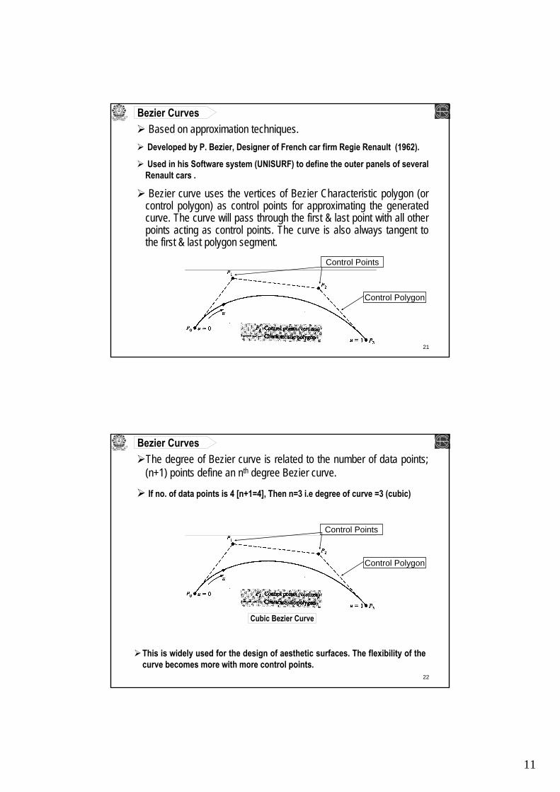
Bezier CurvesBased on approximation techniques.Developed by P. Bezier, Designer of French car firm Regie Renault (1962).
Used in his Software system (UNISURF) to define the outer panels of several Renault cars .
Bezier curve uses the vertices of Bezier Characteristic polygon (or control polygon) as control points for approximating the generated curve. The curve will pass through the first & last point with all other points acting as control points. The curve is also always tangent to the first & last polygon segment.
Control Polygon
Control Points
22
Bezier CurvesThe degree of Bezier curve is related to the number of data points; (n+1) points define an nth degree Bezier curve.
If no. of data points is 4 [n+1=4], Then n=3 i.e degree of curve =3 (cubic)
Control Polygon
Control Points
This is widely used for the design of aesthetic surfaces. The flexibility of the curve becomes more with more control points.
Cubic Bezier Curve

12
23
Bezier Curves
Control Polygon
Control Points
Mathematically, for (n+1) control points, the Bezier curve is defined by polynomial of degree n:
P(u) is a point on the curve, Pi is a control point
Bi,n(u) are the Berntein polynomials
24
C(n,i) is the binomial coefficient
Bezier Curves
13
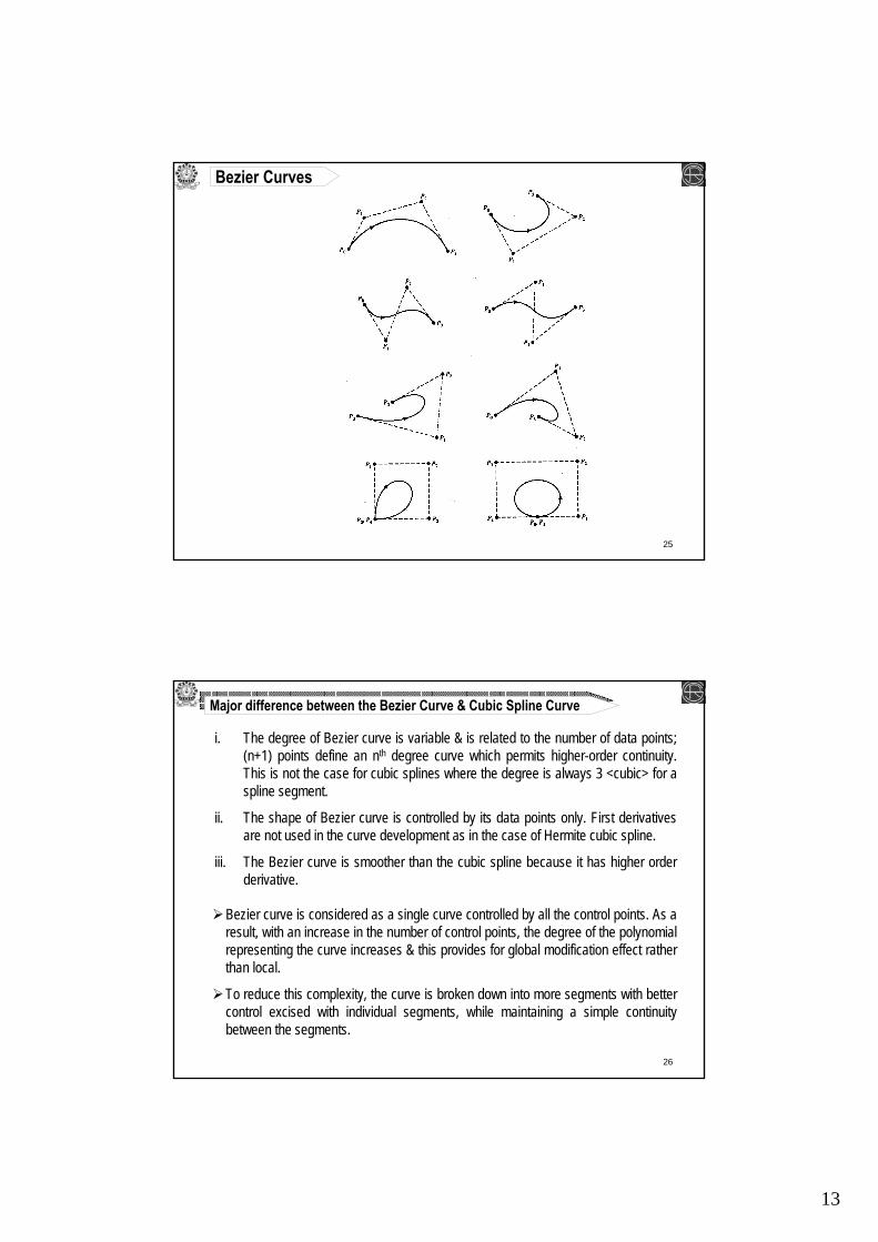
25
Bezier Curves
26
Major difference between the Bezier Curve & Cubic Spline Curve
i. The degree of Bezier curve is variable & is related to the number of data points; (n+1) points define an nth degree curve which permits higher-order continuity. This is not the case for cubic splines where the degree is always 3 <cubic> for a spline segment.
ii. The shape of Bezier curve is controlled by its data points only. First derivatives are not used in the curve development as in the case of Hermite cubic spline.
iii. The Bezier curve is smoother than the cubic spline because it has higher order derivative.
Bezier curve is considered as a single curve controlled by all the control points. As a result, with an increase in the number of control points, the degree of the polynomial representing the curve increases & this provides for global modification effect rather than local.
To reduce this complexity, the curve is broken down into more segments with better control excised with individual segments, while maintaining a simple continuity between the segments.
14
27
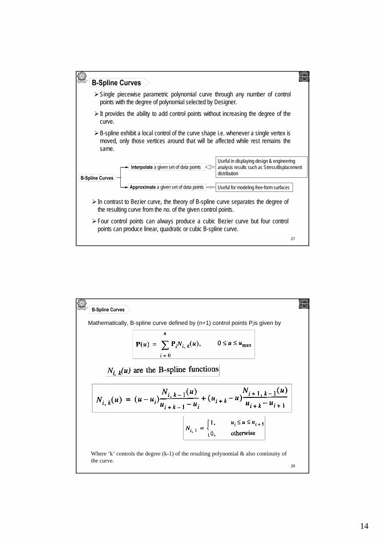
B-Spline CurvesSingle piecewise parametric polynomial curve through any number of control points with the degree of polynomial selected by Designer.
It provides the ability to add control points without increasing the degree of the curve.
B-spline exhibit a local control of the curve shape i.e. whenever a single vertex is moved, only those vertices around that will be affected while rest remains the same.
B-Spline CurvesApproximate a given set of data points
Interpolate a given set of data pointsUseful in displaying design & engineering analysis results such as Stress/displacement distribution
Useful for modeling free-form surfaces
In contrast to Bezier curve, the theory of B-spline curve separates the degree of the resulting curve from the no. of the given control points.
Four control points can always produce a cubic Bezier curve but four control points can produce linear, quadratic or cubic B-spline curve.
28
Mathematically, B-spline curve defined by (n+1) control points Piis given by
B-Spline Curves
Where ‘k’ controls the degree (k-1) of the resulting polynomial & also continuity of the curve.

15
29
B-Spline Curves
Local control of B-spline curve
It provides the ability to add control points without increasing the degree of the curve.
B-spline exhibit a local control of the curve shape i.e. whenever a single vertex is moved, only those vertices around that will be affected while rest remains the same.
30
are generalization of the curve & surface theories.
are almost exclusively used by modern CAD-CAM-CAE systems to provide a unified approach to formulate & represent curves & surfaces.
provide a convenient design tool to create smooth curves & surfaces interactively.
Rational Curve: is defined by algebraic ratio of two polynomials while a non-rational curve is defined by one polynomial.
NURBS Non-Uniform Rational B- Spline
n
i i i,ni 0
n
i i,ni 0
P w B (u)P(u) ;
w B (u)
=
=
=∑
∑Rational form of Bezier Curves
where wi is the weighting factor for each of the vertex.
0 ≤ u ≤ 1

16
31
Disadvantages
NURBS are considered a unified representation that can be define both synthetic (like Bezier, B-spline etc.) & analytic (i.e. circle, conics etc.) curves & surfaces. Any curve or surface can be formulated using NURBS. It can represent all curves, surfaces, & solid entities, allowing unification & conversion from one CAD system to another via exchange standards (like IGES,, STEP etc.). Their related algorithm are stable & accurate. This unified representation also have the advantage of reducing the database complexity & the number of procedures required in CAD system for display & manipulation of geometric entities.
Advantages
Simple curves (like arcs, circles, conics) require more data to define as NURBS than traditional way.
NURBS
32
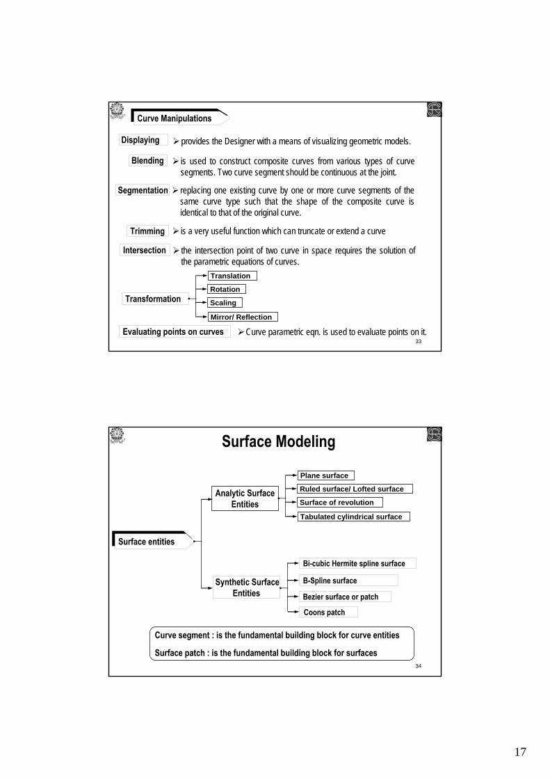
Curve Manipulations
Blending
Segmentation
Displaying
Trimming
Evaluating points on curves
Intersection
Transformation
The effective use of analytic & synthetic curves in a design environment depends mainly on their manipulation.
Translation
Rotation
Scaling
Mirror/ Reflection
17
33
Curve Manipulations
Blending
Segmentation
Displaying
Trimming
Evaluating points on curves
Intersection
Transformation
Translation
Rotation
Scaling
Mirror/ Reflection
provides the Designer with a means of visualizing geometric models.
is used to construct composite curves from various types of curve segments. Two curve segment should be continuous at the joint.
replacing one existing curve by one or more curve segments of the same curve type such that the shape of the composite curve is identical to that of the original curve.
is a very useful function which can truncate or extend a curve
the intersection point of two curve in space requires the solution of the parametric equations of curves.
Curve parametric eqn. is used to evaluate points on it.
34
Surface Modeling
Surface entities
Synthetic Surface Entities
Analytic Surface Entities
Plane surface
Ruled surface/ Lofted surface
Surface of revolution
Tabulated cylindrical surface
Coons patch
B-Spline surface
Bi-cubic Hermite spline surface
Bezier surface or patch
Curve segment : is the fundamental building block for curve entities
Surface patch : is the fundamental building block for surfaces

18
35
Plane Surface
Ruled Surface
is the simplest surface which requires three non-coincident points to define a plane.
The plane surface can be used to generate cross-sectional view by intersecting a surface model with it.
is a surface constructed by transitioning between two or more curves by using linear blending between each section of the surface
It interpolates linearly between two boundary curves that define the surface.
Lofted Surfaceis a surface constructed by transitioning between two or more curves by a smooth i.e. higher order blending between each section of the surface.
Used for modeling engine manifolds, turbine blades etc.
36
Surface of Revolutionis an axi-symmetric surface that can model axi-symmetric objects.
is generated by a rotating a planar wireframe entity in space about the axis of symmetry a certain angle.
Tabulated Cylindrical Surfaceis a surface generated by translating a planar curve a certain distance along a specified direction (axis of cylinder).
Plane of the curve is perpendicular to the axis of the cylinder.
is used to generate surfaces that have identical curved cross-sections.

19
37
B-spline Surface
Bi-cubic Hermite Spline Surface
Bezier Surface
It connects four corner data points & utilizes a bi-cubic equation.
is a synthetic surface that approximates given input data i.e. it doesnot pass through all given data points.
Allows only global control of the surface.
is a synthetic surface that can either approximate or interpolate given input data.
Permits local control of the surface.
Coons patches / surfaceCoons patch or surface is obtained by blending four boundary curves.
is used to create surfaces using curves that form closed boundaries.
the single patch can be extended in both the directions by adding further patches.
38
Surface Manipulations
Blending
Segmentation
Displaying
Trimming
Evaluating points & curves on surfaces
Intersection
Transformation
Projection

20
39
Solid Modeling
Solid model are known to be informationally more complete, valid & unambiguous representation of objects than its wireframe or surface model.
The completeness & unambiguity of a solid model are attributed to the fact that CAD database stores both its geometry & topology.
Solid models are complete & unambiguous but they are not unique because same object may be constructed in various ways.
Solid modeling has been acknowledged as the technological solution to automating & integrating design & manufacturing functions like…
Design / Engineering Analysis Drafting MRPCAPP, CNC tool path generation
Computer-Aided Inspection & Quality control
40
Geometry
A solid model of an object consists of both the geometrical & topological data of the object.
- Geometry of an object defines the actual dimensions of its entities.
Topology
- Topology of an object defines the connectivity & associativity of the entities.- it determines the relational information between entities.
From user point of view,Geometry is visible.Topology is considered to be non-graphical relational information that is stored in solid model databases & are not visible to users.
21
41
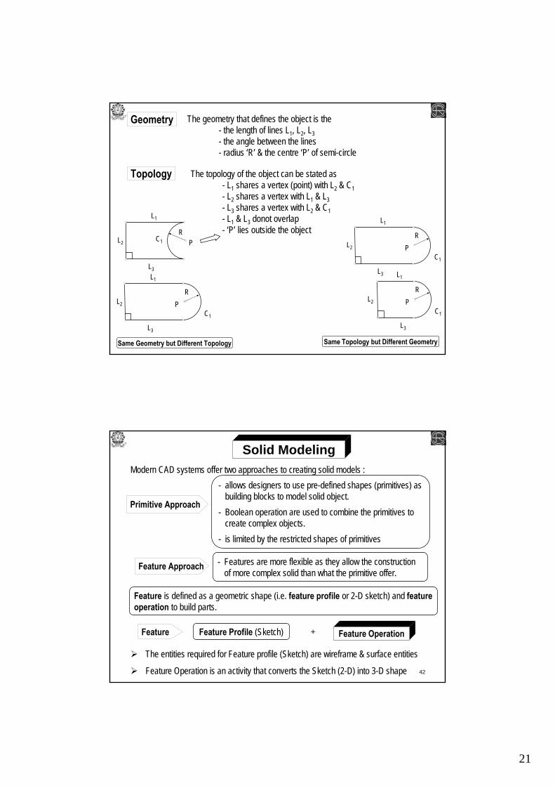
Geometry
Topology
The geometry that defines the object is the - the length of lines L1, L2, L3- the angle between the lines- radius ‘R’ & the centre ‘P’ of semi-circle
The topology of the object can be stated as- L1 shares a vertex (point) with L2 & C1- L2 shares a vertex with L1 & L3- L3 shares a vertex with L2 & C1- L1 & L3 donot overlap- ‘P’ lies outside the object
L1
C1L2
L3
RP
L1
C1
L2
L3
RP
L1
C1
L2
L3
RP
L1
C1
L2
L3
RP
Same Geometry but Different Topology Same Topology but Different Geometry
42
Solid ModelingModern CAD systems offer two approaches to creating solid models :
Feature Approach
Primitive Approach
- allows designers to use pre-defined shapes (primitives) as building blocks to model solid object.
- Boolean operation are used to combine the primitives to create complex objects.
- is limited by the restricted shapes of primitives
- Features are more flexible as they allow the construction of more complex solid than what the primitive offer.
Feature is defined as a geometric shape (i.e. feature profile or 2-D sketch) and feature operation to build parts.
Feature Feature Profile (Sketch) Feature Operation+
The entities required for Feature profile (Sketch) are wireframe & surface entities
Feature Operation is an activity that converts the Sketch (2-D) into 3-D shape

22
43
Constraints
Geometric Constraints Dimension Constraints
CoincidenceConcentricity
Fix
Parallelism
Tangency
Geometric constraints is defined as a geometric condition that relates two or more sketch entities.
Equidistant pointMid point
Horizontal
Perpendicular
Vertical
44
Constraint-based Feature ModelingSelect a Sketch Plane
Sketching the feature profile (2D profile)
Create Base Feature
Apply Geometric & Dimensional Constraints
Apply feature operations
Combine feature to build part- is considered the best tool to create solids because of its ability to edit & change the
shape of the solid in the future by using its relations & constraints. It has flexibility to create complex shape.
23
45
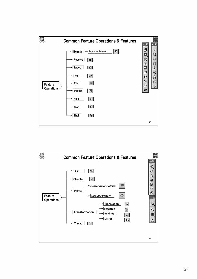
Feature Operations
Revolve
Sweep
Extrude
Loft
Hole
Common Feature Operations & Features
Slot
Shell
Protruded Feature
Rib
46
Feature Operations
Fillet
Chamfer
Pattern
Common Feature Operations & Features
Thread
Rectangular Pattern
Circular Pattern
Transformation
Translation
Rotation
Scaling
Mirror

24
47
Extruded or Protruded feature
Common Features
Extrude command is used to create a solid object by extruding a given closed profile.
It requires a closed profile (sketch of cross-section of solid object) & an extrusion vector (length & direction).
The extrusion direction is always perpendicular to the sketch plane of the profile.
Revolved featureRevolve command is used to create an axi-symmetric objects by revolving the selected geometry about an axis.
It requires a profile (sketch of cross-section of solid object) & a revolution vector (axis & angle of revolution).
The axis of revolution is always in the sketch plane of the profile.
48
Common Features
is a generalization of extrusion.
Creates a feature by moving a sketch (closed or open) along a linear or non-linear path, which is not necessarily perpendicular to the sketch plane.
Use to blend multiple cross-section (two or more) along the linear or non-linear guide curve to create a solid.
Sweep feature
Loft feature
Hole featureis equivalent to subtracting a cylinder from a solid.
Simple and Taper hole
Counter-bored hole
Counter-sunk hole
Threaded hole
Type of Hole feature
25
49
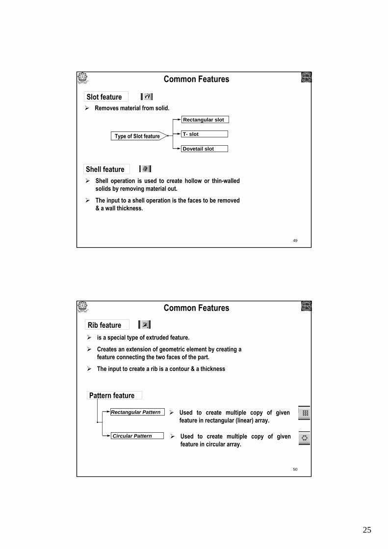
Common Features
Removes material from solid.
Shell operation is used to create hollow or thin-walled solids by removing material out.
The input to a shell operation is the faces to be removed & a wall thickness.
Rectangular slot
T- slot
Dovetail slot
Type of Slot feature
Slot feature
Shell feature
50
Common Features
Rib featureis a special type of extruded feature.
Creates an extension of geometric element by creating a feature connecting the two faces of the part.
The input to create a rib is a contour & a thickness
Pattern feature
Rectangular Pattern
Circular Pattern
Used to create multiple copy of given feature in rectangular (linear) array.
Used to create multiple copy of given feature in circular array.
26
51
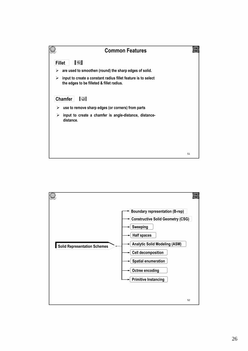
Common Features
are used to smoothen (round) the sharp edges of solid.
input to create a constant radius fillet feature is to select the edges to be filleted & fillet radius.
Fillet
Chamferuse to remove sharp edges (or corners) from parts
input to create a chamfer is angle-distance, distance-distance.
52
Solid Representation Schemes
Constructive Solid Geometry (CSG)
Boundary representation (B-rep)
Sweeping
Half spaces
Analytic Solid Modeling (ASM)
Cell decomposition
Spatial enumeration
Octree encoding
Primitive Instancing

27
53
Boundary representation (B-rep)B-rep is based on the topological notion that an object is boundedby a set of faces.
A face is a closed, orientable & bounded (by edges) surface. Each face is bounded by edges & each edge (bounded curve) is bounded by vertices.
B-rep model of an object consists of faces, edges, vertices.
Vertices (v)
Edge (E)
Face (F)
- The database of a boundary model contains both its topology & its geometry. Topology & Geometry are interrelated & cannot be separated entirely from each other
54
Disadvantages
B-rep is very appropriate to construct solid models of unusual or complex shapes ( like turbine blades, auto body etc.) that are difficult to build using primitives. It is relatively simple to convert a B-rep model into a wireframemodel because the model’s boundary definition is similar to the wireframe definition.
Advantages
It requires large amounts of storage because it stores the explicit definition of model boundaries i.e. faces, edges & vertices which tend to grow fairly fast for complex model.
B - rep

28
55
Constructive Solid Geometry (CSG)CSG model is based on the topological notion that a physical object can be divided into set of primitives (basic elements & shapes) that can be combined in a certain order following a set of rules (Boolean operation) to form the object.Primitives are considered as building block
Primitives are simple, basic shapes which can be combined by a mathematical set of Boolean operations to create the complex solid object.
Cylinder ConeBlock WedgeSphere
Primitives
56
Intersection (∩)
Union (U)
Difference (-)
Boolean Operations
Used to combine or add two primitives/
objects
Intersecting two primitives give a
shape equal to their common value
Used to subtract one primitive from other & results in shape equal
to the difference in their volume

29
57
Disadvantages
It is easy to construct out of primitives & Boolean operation. It is concise & requires minimum storage.
Advantages
Major disadvantage of CSG is in its inability to represent sculptured surfaces i.e. non-analytical (synthetic surface) cannot be modeled using CSG scheme.
CSG
- Modern CAD systems provide both approaches to increase their modeling domain
58
Solid Model-based Down-stream Application
Solid Model-based Drafting
Solid Model-based Mechanism Design
Solid Model-based Assembly Design
Finite Element Modeling from Solid Models
CNC machining based on Solid Modeling …