55 Series Exit Device - Security Technologies
20
55 Series Exit Device
Transcript of 55 Series Exit Device - Security Technologies
55 Series Exit Device

IndexIntroduction. . . . . . . . . . . . . . . . . . . . . . . . . . . . . . . . . . . . . . . . . . . . . . . . . . . . . . . . . . . . . . . . . . . . . . . . . . . 3
Exit Hardware Rim device. . . . . . . . . . . . . . . . . . . . . . . . . . . . . . . . . . . . . . . . . . . . . . . . . . . . . . . . . . . . . . . . . . . . . . . . . . . . 4Mortise lock device . . . . . . . . . . . . . . . . . . . . . . . . . . . . . . . . . . . . . . . . . . . . . . . . . . . . . . . . . . . . . . . . . . . . . 5Concealed vertical rod device. . . . . . . . . . . . . . . . . . . . . . . . . . . . . . . . . . . . . . . . . . . . . . . . . . . . . . . . . . . . . . 6Wood door concealed vertical rod device . . . . . . . . . . . . . . . . . . . . . . . . . . . . . . . . . . . . . . . . . . . . . . . . . . . . . 6
Fire Exit Hardware Mortise lock device . . . . . . . . . . . . . . . . . . . . . . . . . . . . . . . . . . . . . . . . . . . . . . . . . . . . . . . . . . . . . . . . . . . . . 7Concealed vertical rod device. . . . . . . . . . . . . . . . . . . . . . . . . . . . . . . . . . . . . . . . . . . . . . . . . . . . . . . . . . . . . . 8Wood door concealed vertical rod device . . . . . . . . . . . . . . . . . . . . . . . . . . . . . . . . . . . . . . . . . . . . . . . . . . . . . 9
Trim Selection . . . . . . . . . . . . . . . . . . . . . . . . . . . . . . . . . . . . . . . . . . . . . . . . . . . . . . . . . . . . . . . . . . . . . . . . . . . . . . . . . 10-11
Options and Conversion kit . . . . . . . . . . . . . . . . . . . . . . . . . . . . . . . . . . . . . . . . . . . . . . . . . . . . . . . . . . . . . . . . . . . . . . . . 14Accessories Cylinders . . . . . . . . . . . . . . . . . . . . . . . . . . . . . . . . . . . . . . . . . . . . . . . . . . . . . . . . . . . . . . . . . . . . . . . . . . . . 14
Optional levers. . . . . . . . . . . . . . . . . . . . . . . . . . . . . . . . . . . . . . . . . . . . . . . . . . . . . . . . . . . . . . . . . . . . . . . . 11
Additional Information ANSI grade, type & function . . . . . . . . . . . . . . . . . . . . . . . . . . . . . . . . . . . . . . . . . . . . . . . . . . . . . . . . . . . . . 16Device dimensions. . . . . . . . . . . . . . . . . . . . . . . . . . . . . . . . . . . . . . . . . . . . . . . . . . . . . . . . . . . . . . . . . . . . . 17Double door applications . . . . . . . . . . . . . . . . . . . . . . . . . . . . . . . . . . . . . . . . . . . . . . . . . . . . . . . . . . . . . . . . 15Finishes . . . . . . . . . . . . . . . . . . . . . . . . . . . . . . . . . . . . . . . . . . . . . . . . . . . . . . . . . . . . . . . . . . . . . . . . . . . . . 16Fire label ratings/applications . . . . . . . . . . . . . . . . . . . . . . . . . . . . . . . . . . . . . . . . . . . . . . . . . . . . . . . . . . . . . 16Handing. . . . . . . . . . . . . . . . . . . . . . . . . . . . . . . . . . . . . . . . . . . . . . . . . . . . . . . . . . . . . . . . . . . . . . . . . . . . . 17How-To-Order Information. . . . . . . . . . . . . . . . . . . . . . . . . . . . . . . . . . . . . . . . . . . . . . . . . . . . . . . . . . . . . . . 17Nomenclature . . . . . . . . . . . . . . . . . . . . . . . . . . . . . . . . . . . . . . . . . . . . . . . . . . . . . . . . . . . . . . . . . . . . . . . . 18Strike application/minimum stile . . . . . . . . . . . . . . . . . . . . . . . . . . . . . . . . . . . . . . . . . . . . . . . . . . . . . . . . . . 12Strike information . . . . . . . . . . . . . . . . . . . . . . . . . . . . . . . . . . . . . . . . . . . . . . . . . . . . . . . . . . . . . . . . . . . . . 13
222
55 Exit Devices
© 2003 Ingersoll-Rand. May be copied for use with specification submittal.22
3
IntroductionThe proper selection and application of exit hardware, in addition to safety, are major concerns to all responsiblemanufacturers. Exit devices are a critical part of a door opening or access system and will provide safe and reliable service when properly applied and maintained. It is the policy of Von Duprin Division, Ingersoll-RandCompany, to design and manufacture exit devices to a high standard of quality and reliability in accordancewith accepted U.S. domestic and international standards. All 55 series exit devices are UL listed for AccidentHazard or Fire Exit Hardware, and are tested in accordance to ANSI A156.3, 1994, Grade I.
It is intended that the information included in this publication, when properly used, will provide clear and reliable guidelines to the proper general selection and application. However, the scope of the information is necessarily limited.
Unusual operating conditions and environments, and other external influences can affect the proper applicationof the products represented. Modifications of these products will also affect UL listings. It is recommendedwhenever an unusual application condition exists, or when any modification of a product is considered, ourengineers review the application.
Application engineering services are available to help ensure proper selection or to review any areas whereusers of Von Duprin products may have questions.
3
55 Exit Devices
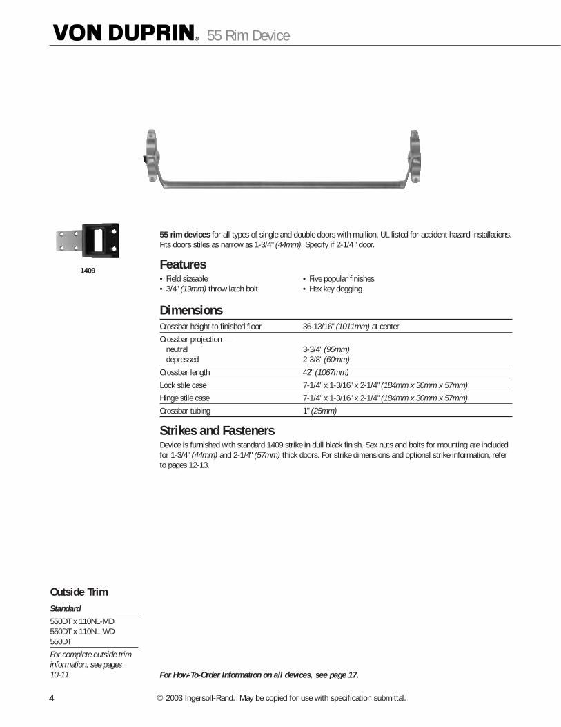
55 rim devices for all types of single and double doors with mullion, UL listed for accident hazard installations.Fits doors stiles as narrow as 1-3/4" (44mm). Specify if 2-1/4 " door.
Features• Field sizeable • Five popular finishes• 3/4" (19mm) throw latch bolt • Hex key dogging
DimensionsCrossbar height to finished floor 36-13/16" (1011mm) at center
Crossbar projection —neutral 3-3/4" (95mm)depressed 2-3/8" (60mm)
Crossbar length 42" (1067mm)
Lock stile case 7-1/4" x 1-3/16" x 2-1/4" (184mm x 30mm x 57mm)
Hinge stile case 7-1/4" x 1-3/16" x 2-1/4" (184mm x 30mm x 57mm)
Crossbar tubing 1" (25mm)
Strikes and Fasteners Device is furnished with standard 1409 strike in dull black finish. Sex nuts and bolts for mounting are includedfor 1-3/4" (44mm) and 2-1/4" (57mm) thick doors. For strike dimensions and optional strike information, referto pages 12-13.
For How-To-Order Information on all devices, see page 17.
1409
Outside TrimStandard
550DT x 110NL-MD550DT x 110NL-WD550DT
For complete outside triminformation, see pages 10-11.
444
55 Rim Device
© 2003 Ingersoll-Rand. May be copied for use with specification submittal.44

5575 mortise lock devices for all types of single and double doors. UL listed for accident hazard installations.
The 7500 mortise lock is equipped with a 3/4" (19mm) anti-friction latch bolt which is field reversible withoutremoving the lock from the door. It has a non-handed auxiliary bolt for deadlocking and a faceplate with anadjustable bevel. Wood doors required 589 cover plate.
Features• Field sizeable • Latch bolt deadlocking• 3/4" (19mm) throw latch bolt • Five popular finishes
DimensionsCrossbar height to finished floor 36-13/16" (935mm) at centerLatch bolt height to finished floor 40-3/32" (1018mm) at center
Crossbar projection —neutral 3-3/4" (95mm)depressed 2-3/8" (60mm)
Crossbar length 42" (1067mm)
Lock stile case 7-1/4" x 1-3/16" x 2-1/4" (184mm x 30mm x 57mm)
Hinge stile case 7-1/4" x 1-3/16" x 2-1/4" (184mm x 30mm x 57mm)
Lock case 4-5/8" x 5-3/4" x 1-1/16" (117mm x 146mm x 27mm)
Faceplate 1-1/4" x 8" x 7/32" (32mm x 203mm x 6mm)
Cylinder backset 2-3/4" (70mm)
Crossbar tubing 1" (25mm)
Strikes and Fasteners Device is furnished with standard 575 strike in dull black finish. Sex nuts and bolts for mounting are includedfor 1-3/4" (44mm) and 2-1/4" (57mm) thick doors. Optional strikes and finishes are available. For strike applications, dimensions, and minimum door stile information, refer to pages 12-13.
For How-To-Order Information on all devices, see page 17.
575
Outside TrimStandard
375L550DT
For complete outside triminformation, see pages 10-11.
5
55 Mortise Lock Device

5547 concealed vertical rod devices for use on single or double metal doors.UL listed for accident hazard installations and fits door stiles as narrow as 1-3/4" (44mm). Specify if 2-1/4 " door.
5547WDC concealed vertical rod devices for use on single or double wood doors.Fits door stiles as narrow as 4" (102mm).
Features• Field sizeable • Five popular finishes• 1/2" (13mm) (MD) or 5/8" (16mm) • Hex key dogging
WD throw latch bolt
DimensionsCrossbar height to finished floor 36-13/16" (935mm) at centerCrossbar projection —
neutral 3-3/4" (95mm)depressed 2-3/8" (60mm)
Crossbar length 42" (1067mm)
Lock stile case 7-1/4" x 1-3/16" x 2-1/4" (184mm x 30mm x 57mm)
Hinge stile case 7-1/4" x 1-3/16" x 2-1/4" (184mm x 30mm x 57mm)
Vertical rods-hexagon 3/8" (10mm) adjustable top rod
Crossbar tubing 1" (25mm)Note: Maximum door undercut, 1/4" (6mm).
Strikes and Fasteners 5547 is furnished standard with 471U and 304L.
5547WDC is furnished standard with 338 and 304L.
Sex nuts and bolts for mounting are included for 1-3/4" (44mm) and 2-1/4" (57mm) thick doors. For strike dimen-sions and optional strike information, refer to pages 12-13.
For How-To-Order Information on all devices, see page 17.
Outside TrimStandard
555NL550DT376T x 550DT
Optional
Wood Door556NL550DT376T (WDC) x 550DT
For complete outside triminformation, see pages 10-11.
471U 304L 338
666
55 Concealed Vertical Rod Device
© 2003 Ingersoll-Rand. May be copied for use with specification submittal.66
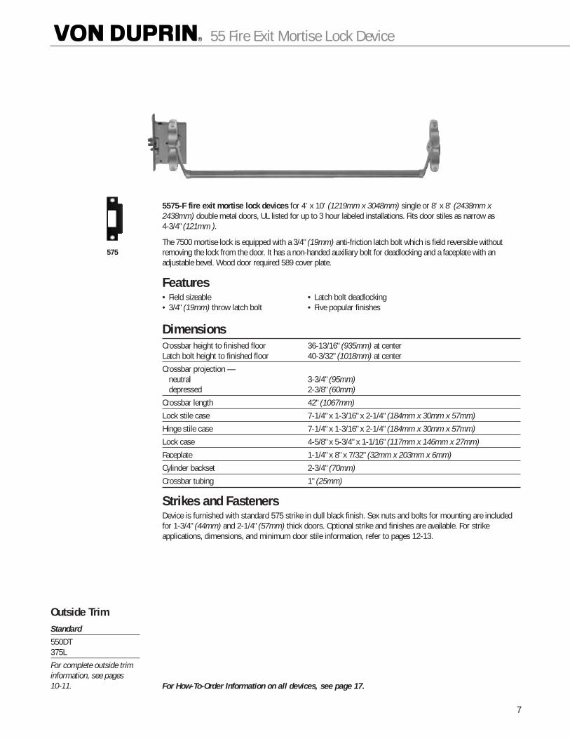
5575-F fire exit mortise lock devices for 4' x 10' (1219mm x 3048mm) single or 8' x 8' (2438mm x2438mm) double metal doors, UL listed for up to 3 hour labeled installations. Fits door stiles as narrow as 4-3/4" (121mm ).
The 7500 mortise lock is equipped with a 3/4" (19mm) anti-friction latch bolt which is field reversible withoutremoving the lock from the door. It has a non-handed auxiliary bolt for deadlocking and a faceplate with anadjustable bevel. Wood door required 589 cover plate.
Features• Field sizeable • Latch bolt deadlocking• 3/4" (19mm) throw latch bolt • Five popular finishes
DimensionsCrossbar height to finished floor 36-13/16" (935mm) at centerLatch bolt height to finished floor 40-3/32" (1018mm) at center
Crossbar projection —neutral 3-3/4" (95mm)depressed 2-3/8" (60mm)
Crossbar length 42" (1067mm)
Lock stile case 7-1/4" x 1-3/16" x 2-1/4" (184mm x 30mm x 57mm)
Hinge stile case 7-1/4" x 1-3/16" x 2-1/4" (184mm x 30mm x 57mm)
Lock case 4-5/8" x 5-3/4" x 1-1/16" (117mm x 146mm x 27mm)
Faceplate 1-1/4" x 8" x 7/32" (32mm x 203mm x 6mm)
Cylinder backset 2-3/4" (70mm)
Crossbar tubing 1" (25mm)
Strikes and Fasteners Device is furnished with standard 575 strike in dull black finish. Sex nuts and bolts for mounting are includedfor 1-3/4" (44mm) and 2-1/4" (57mm) thick doors. Optional strike and finishes are available. For strike applications, dimensions, and minimum door stile information, refer to pages 12-13.
For How-To-Order Information on all devices, see page 17.
Outside TrimStandard
550DT 375L
For complete outside triminformation, see pages 10-11.
575
7
55 Fire Exit Mortise Lock Device
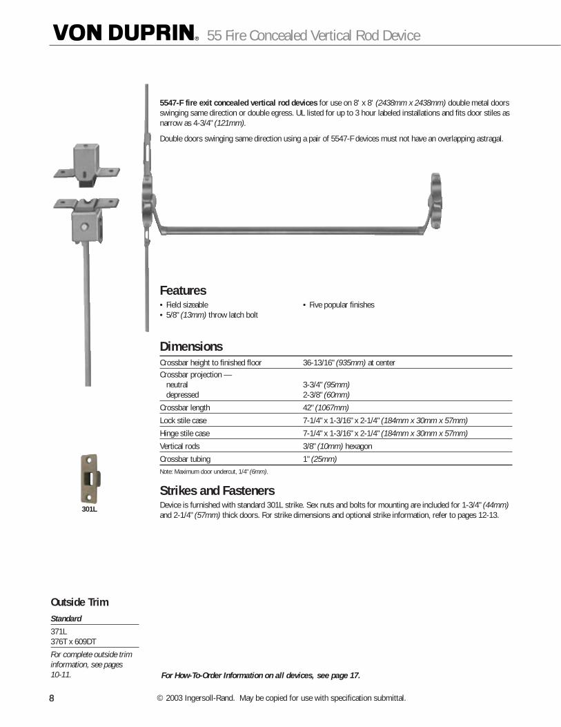
5547-F fire exit concealed vertical rod devices for use on 8' x 8' (2438mm x 2438mm) double metal doorsswinging same direction or double egress. UL listed for up to 3 hour labeled installations and fits door stiles asnarrow as 4-3/4" (121mm).
Double doors swinging same direction using a pair of 5547-F devices must not have an overlapping astragal.
Features• Field sizeable • Five popular finishes• 5/8" (13mm) throw latch bolt
DimensionsCrossbar height to finished floor 36-13/16" (935mm) at centerCrossbar projection —
neutral 3-3/4" (95mm)depressed 2-3/8" (60mm)
Crossbar length 42" (1067mm)
Lock stile case 7-1/4" x 1-3/16" x 2-1/4" (184mm x 30mm x 57mm)
Hinge stile case 7-1/4" x 1-3/16" x 2-1/4" (184mm x 30mm x 57mm)
Vertical rods 3/8" (10mm) hexagon
Crossbar tubing 1" (25mm)Note: Maximum door undercut, 1/4" (6mm).
Strikes and Fasteners Device is furnished with standard 301L strike. Sex nuts and bolts for mounting are included for 1-3/4" (44mm)and 2-1/4" (57mm) thick doors. For strike dimensions and optional strike information, refer to pages 12-13.
For How-To-Order Information on all devices, see page 17.
301L
Outside TrimStandard
371L376T x 609DT
For complete outside triminformation, see pages 10-11.
888
55 Fire Concealed Vertical Rod Device
© 2003 Ingersoll-Rand. May be copied for use with specification submittal.88
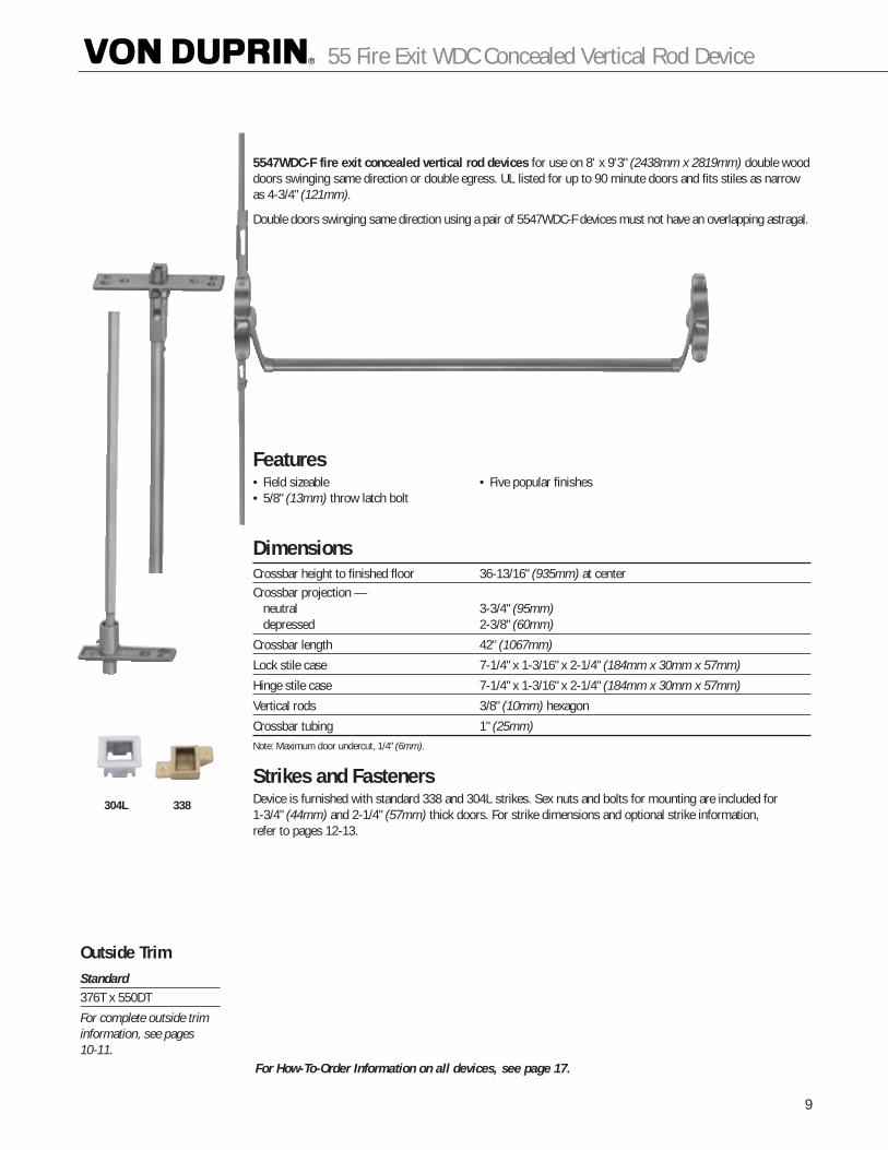
5547WDC-F fire exit concealed vertical rod devices for use on 8' x 9'3" (2438mm x 2819mm) double wooddoors swinging same direction or double egress. UL listed for up to 90 minute doors and fits stiles as narrowas 4-3/4" (121mm).
Double doors swinging same direction using a pair of 5547WDC-F devices must not have an overlapping astragal.
Features• Field sizeable • Five popular finishes• 5/8" (13mm) throw latch bolt
DimensionsCrossbar height to finished floor 36-13/16" (935mm) at centerCrossbar projection —
neutral 3-3/4" (95mm)depressed 2-3/8" (60mm)
Crossbar length 42" (1067mm)
Lock stile case 7-1/4" x 1-3/16" x 2-1/4" (184mm x 30mm x 57mm)
Hinge stile case 7-1/4" x 1-3/16" x 2-1/4" (184mm x 30mm x 57mm)
Vertical rods 3/8" (10mm) hexagon
Crossbar tubing 1" (25mm)Note: Maximum door undercut, 1/4" (6mm).
Strikes and Fasteners Device is furnished with standard 338 and 304L strikes. Sex nuts and bolts for mounting are included for 1-3/4" (44mm) and 2-1/4" (57mm) thick doors. For strike dimensions and optional strike information, refer to pages 12-13.
For How-To-Order Information on all devices, see page 17.
304L 338
Outside TrimStandard376T x 550DT
For complete outside triminformation, see pages 10-11.
9
55 Fire Exit WDC Concealed Vertical Rod Device
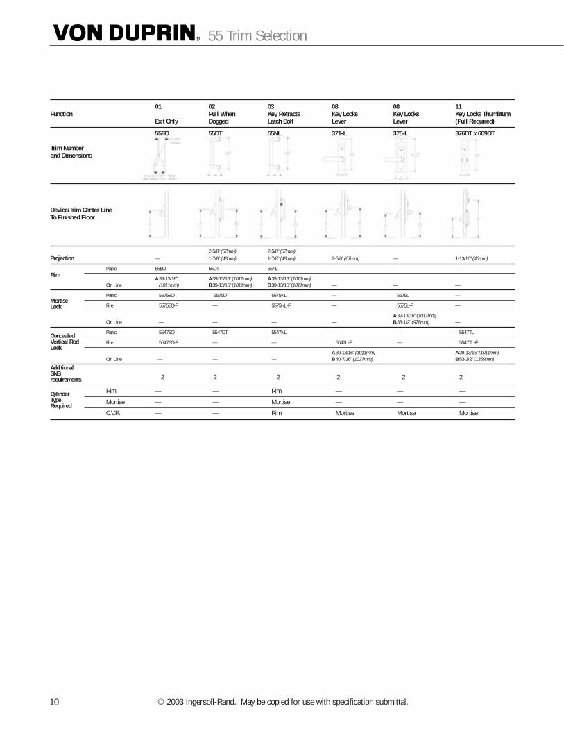
01 02 03 08 08 11Function Pull When Key Retracts Key Locks Key Locks Key Locks Thumbturn
Exit Only Dogged Latch Bolt Lever Lever (Pull Required)
55EO 55DT 55NL 371-L 375-L 376DT x 609DT
Trim Numberand Dimensions
Device/Trim Center LineTo Finished Floor
2-5/8" (67mm) 2-5/8" (67mm)Projection — 1-7/8" (48mm) 1-7/8" (48mm) 2-5/8" (67mm) — 1-13/16" (46mm)
Panic 55EO 55DT 55NL — — —
A 39-13/16" A 39-13/16" (1011mm) A 39-13/16" (1011mm)Ctr. Line (1011mm) B 39-13/16" (1011mm) B 39-13/16" (1011mm) — — — A10
Panic A 5575EO A 5575DT A 5575NL — A 5575L —
Fire A 5575EO-F A — A 5575NL-F —A A 5575L-F —
A 39-13/16" (1011mm)Ctr. Line — A — A — — B 38-1/2" (978mm) —
Panic A 5547EO A 5547DT A 5547NL —A A —A A 5547TL
Fire A 5547EO-F A — A — A 5547L-F A — A 5547TL-F
A 39-13/16" (1011mm) A A 39-13/16" (1011mm)Ctr. Line — A — A — B 40-7/16" (1027mm) B 53-1/2" (1359mm)
AA 2 A 2 A A 2 A 2 A A 2 A 2
Rim — A — A Rim A — A — A —
Mortise — A — A Mortise A — A — A —
C.V.R. — A — A Rim A Mortise A Mortise A Mortise
Rim
MortiseLock
ConcealedVertical RodLock
AdditionalSNBrequirements
CylinderTypeRequired
55 Trim Selection
© 2003 Ingersoll-Rand. May be copied for use with specification submittal.10
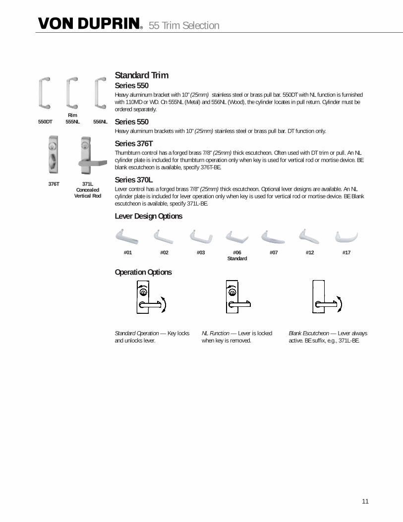
Standard TrimSeries 550Heavy aluminum bracket with 10" (25mm) stainless steel or brass pull bar. 550DT with NL function is furnishedwith 110MD or WD. On 555NL (Metal) and 556NL (Wood), the cylinder locates in pull return. Cylinder must beordered separately.
Series 550Heavy aluminum brackets with 10" (25mm) stainless steel or brass pull bar. DT function only.
Series 376TThumbturn control has a forged brass 7/8" (25mm) thick escutcheon. Often used with DT trim or pull. An NLcylinder plate is included for thumbturn operation only when key is used for vertical rod or mortise device. BEblank escutcheon is available, specify 376T-BE.
Series 370LLever control has a forged brass 7/8" (25mm) thick escutcheon. Optional lever designs are available. An NLcylinder plate is included for lever operation only when key is used for vertical rod or mortise device. BE Blankescutcheon is available, specify 371L-BE.
Lever Design Options
Operation Options
#01 #02 #03 #06 Standard
#07 #12 #17
Standard Operation — Key locksand unlocks lever.
NL Function — Lever is lockedwhen key is removed.
Blank Escutcheon — Lever alwaysactive. BE suffix, e.g., 371L-BE.
550DT 555NL 556NL
376T 371LConcealed
Vertical Rod
11
55 Trim Selection
Rim
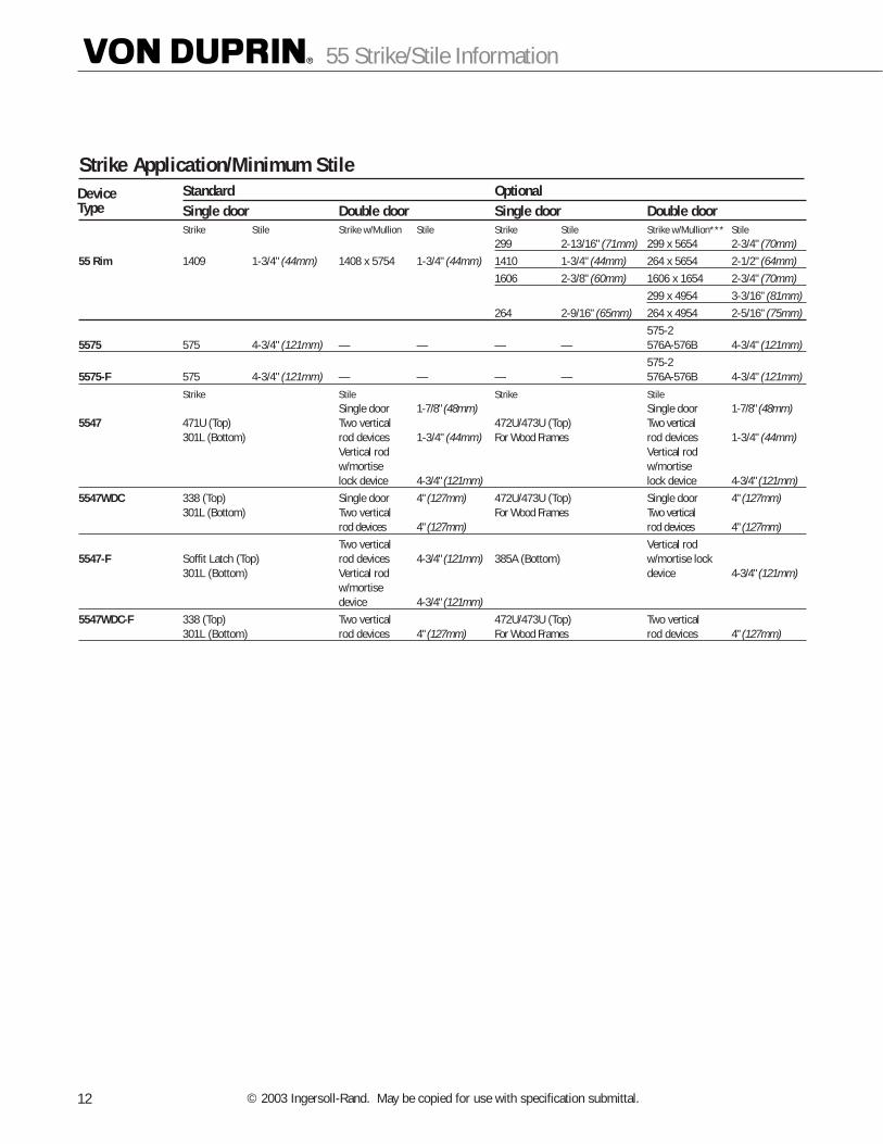
Strike Application/Minimum StileStandard OptionalSingle door Double door Single door Double doorStrike Stile Strike w/Mullion Stile Strike Stile Strike w/Mullion*** Stile
299 2-13/16" (71mm) 299 x 5654 2-3/4" (70mm)55 Rim 1409 1-3/4" (44mm) 1408 x 5754 1-3/4" (44mm) 1410 1-3/4" (44mm) 264 x 5654 2-1/2" (64mm)
1606 2-3/8" (60mm) 1606 x 1654 2-3/4" (70mm)299 x 4954 3-3/16" (81mm)
264 2-9/16" (65mm) 264 x 4954 2-5/16" (75mm)575-2
5575 575 4-3/4" (121mm) — — — — 576A-576B 4-3/4" (121mm)575-2
5575-F 575 4-3/4" (121mm) — — — — 576A-576B 4-3/4" (121mm)Strike Stile Strike Stile
Single door 1-7/8" (48mm) Single door 1-7/8" (48mm)5547 471U (Top) Two vertical 472U/473U (Top) Two vertical
301L (Bottom) rod devices 1-3/4" (44mm) For Wood Frames rod devices 1-3/4" (44mm)Vertical rod Vertical rodw/mortise w/mortiselock device 4-3/4" (121mm) lock device 4-3/4" (121mm)
5547WDC 338 (Top) Single door 4" (127mm) 472U/473U (Top) Single door 4" (127mm)301L (Bottom) Two vertical For Wood Frames Two vertical
rod devices 4" (127mm) rod devices 4" (127mm)Two vertical Vertical rod
5547-F Soffit Latch (Top) rod devices 4-3/4" (121mm) 385A (Bottom) w/mortise lock301L (Bottom) Vertical rod device 4-3/4" (121mm)
w/mortisedevice 4-3/4" (121mm)
5547WDC-F 338 (Top) Two vertical 472U/473U (Top) Two vertical301L (Bottom) rod devices 4" (127mm) For Wood Frames rod devices 4" (127mm)
DeviceType
55 Strike/Stile Information
© 2003 Ingersoll-Rand. May be copied for use with specification submittal.12

3 1/4"(83mm)
1 1/4"(32mm)
For use on 1-3/4" (44mm)or 2-1/4" (57mm) Singledoor and 2-1/4" (57mm)double door with coordinator.
For use on 1-3/4" (44mm)thick doubledoor withcoordinator.
Open back strike for 1-3/4" (44mm)thick double doorswithout coordinator.
Open back strike for 2-1/4" (57mm)thick double doorswithout coordinator.
13
55 Additional Information
Strikes for Rim Devices264 299 1408 1409 — Blade Stop
Projection 13/16" (21mm) Projection 13/16" (21mm) Projection 13/16" (21mm) One per pair of doors
1410 — Integral Stop 1606 1609
Projection 1/2" (13mm) Projection 3/8" (10mm)
Strikes for Vertical Rod Devices301L 304L 338 385A
Mortise 3/4" (19mm) Mortise 13/16" (21mm) Projection 5/8" (16mm) Mortise 2-1/2" (64mm)
471U 472U 473U
Hollow metal frame Wood frame 1-3/4" (44mm) thick doors Wood frame 2-1/4" (57mm) thick doors
Strikes for Mortise Lock Devices575 575-2 576A 576B
1/2
3/16"
(13mm)
(48mm)(5mm)17/8
(48mm)17/8"
(44mm)13/4"

CylindersCylinders are not furnished with device or trim and must be specifiedwhen ordering. Rim and concealed vertical rod exit devices use rim type cylinders. Mortise lock exit devices and series 370 controls usemortise type cylinders.
Conversion Kit — NLFor converting 55DT or 55EO to 55NL for night latch function. The kitincludes 110NL cylinder assembly and cam. The 550DT trim and 3216rim cylinder are not included.Order 55CK-NL, specify finish.
Mortise — 3215 (Schlage D502-191 cam)
Rim — 3216
55 Accessories
© 2003 Ingersoll-Rand. May be copied for use with specification submittal.14
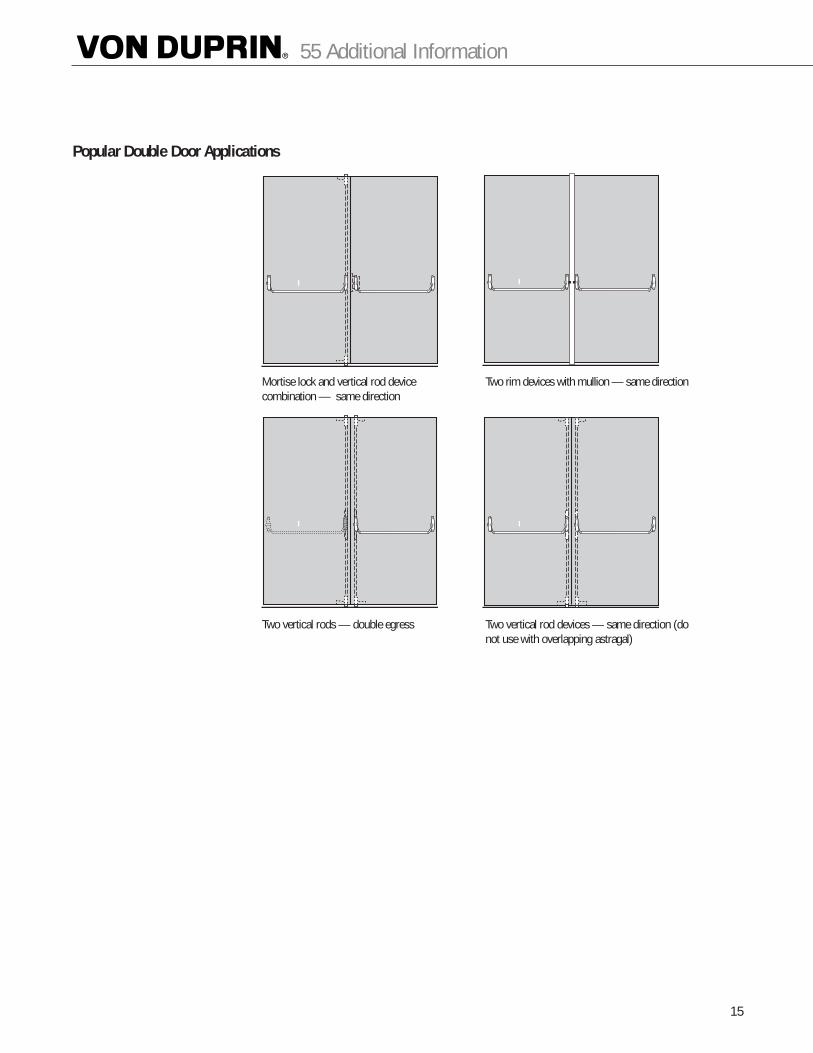
Popular Double Door Applications
Mortise lock and vertical rod device combination — same direction
Two rim devices with mullion — same direction
Two vertical rods — double egress Two vertical rod devices — same direction (donot use with overlapping astragal)
15
55 Additional Information
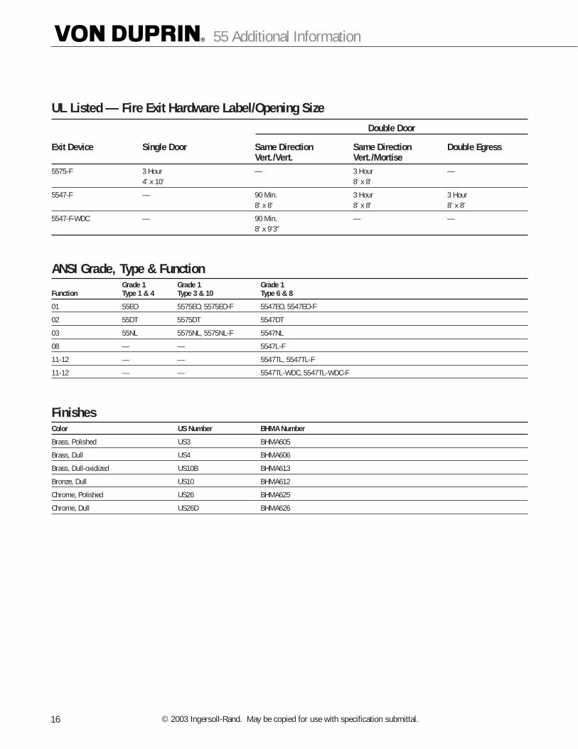
UL Listed — Fire Exit Hardware Label/Opening SizeDouble Door
Exit Device Single Door Same Direction Same Direction Double EgressVert./Vert. Vert./Mortise
5575-F 3 Hour — 3 Hour —4' x 10' 8' x 8'
5547-F — 90 Min. 3 Hour 3 Hour8' x 8' 8' x 8' 8' x 8'
5547-F-WDC — 90 Min. — —8' x 9'3"
ANSI Grade, Type & FunctionGrade 1 Grade 1 Grade 1
Function Type 1 & 4 Type 3 & 10 Type 6 & 8
01 55EO 5575EO, 5575EO-F 5547EO, 5547EO-F
02 55DT 5575DT 5547DT
03 55NL 5575NL, 5575NL-F 5547NL
08 — — 5547L-F
11-12 — — 5547TL, 5547TL-F
11-12 — — 5547TL-WDC, 5547TL-WDC-F
FinishesColor US Number BHMA Number
Brass, Polished US3 BHMA605
Brass, Dull US4 BHMA606
Brass, Dull-oxidized US10B BHMA613
Bronze, Dull US10 BHMA612
Chrome, Polished US26 BHMA625
Chrome, Dull US26D BHMA626
55 Additional Information
© 2003 Ingersoll-Rand. May be copied for use with specification submittal.16

How-To-Order InformationRim and mortise lock devices, specify:1. Exit device model number and trim selection.
Examples: 55EO (exit only and no outside trim).55DT (includes standard 555 DT trim).
2. Door width if greater than 4' (1219mm).3. Door thickness if other than 1-3/4" (44mm).4. Door and frame material if other than hollow metal.5. Finish, see page 16.6. Handing, LHR or RHR. See below.
Vertical rod devices, specify:1. Exit device model number and trim selection.
Examples: 5547EO (exit only and no outside trim).5547NL (includes standard 555 NL trim).
2. Door width if greater than 4' (1219mm).3. Door thickness if other than 1-3/4" (44mm).4. Door height if other than 8' (2438mm), extension
rods must be ordered.5. Door and frame material if other than hollow metal.6. Finish, see page 16.7. Handing, LHR or RHR. See below.
Dimensions
Handing of Doors
Left HandOrientation
Right HandOrientation
LHR(Left hand reverse)
RHR(Right hand reverse)
Outside
Standard 3-3/4" (96mm)Depressed 2-1/4" (57mm)
17
55 Additional Information
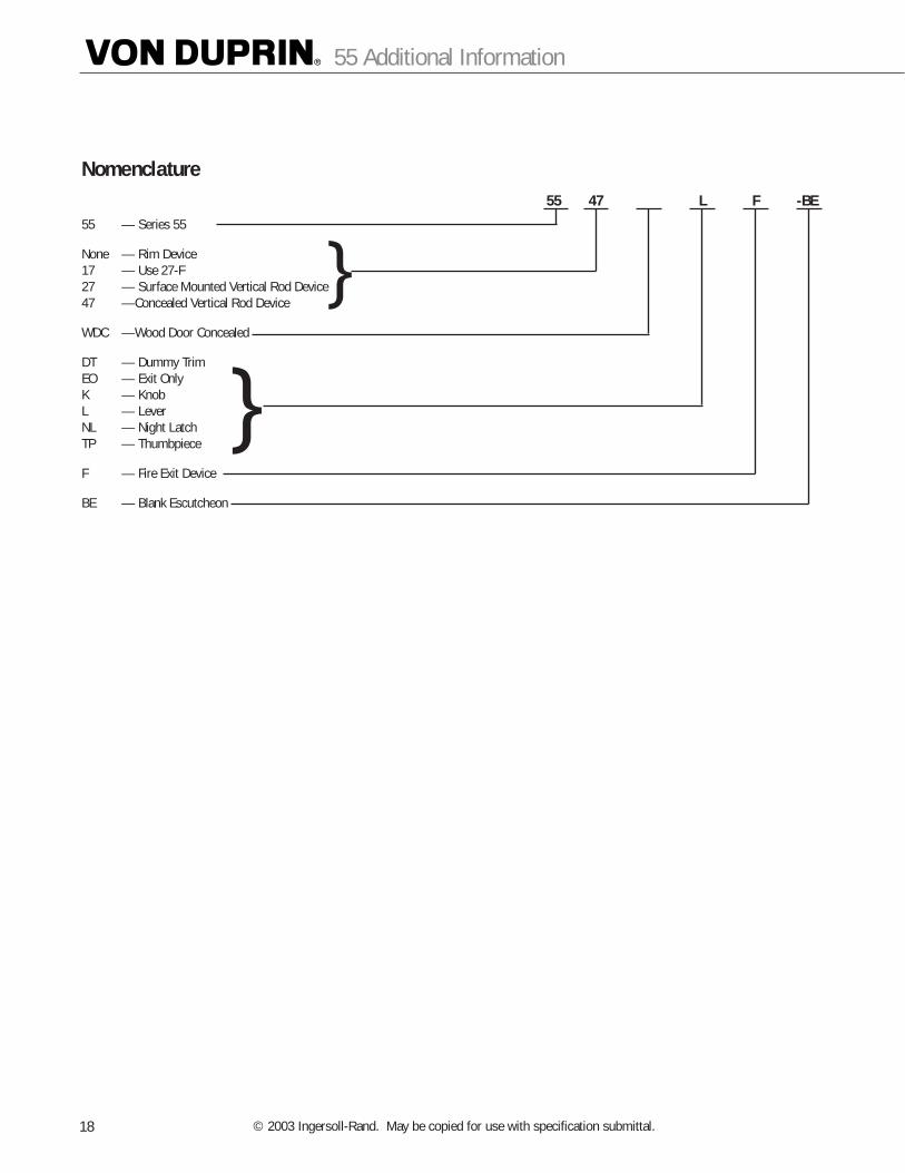
Nomenclature
55 — Series 55
None — Rim Device17 — Use 27-F27 — Surface Mounted Vertical Rod Device47 —Concealed Vertical Rod Device
WDC —Wood Door Concealed
DT — Dummy TrimEO — Exit OnlyK — KnobL — LeverNL — Night LatchTP — Thumbpiece
F — Fire Exit Device
BE — Blank Escutcheon
55 47 L F -BE
}
}
55 Additional Information
© 2003 Ingersoll-Rand. May be copied for use with specification submittal.18

19
55 Additional Information

©2003 Ingersoll-Rand Form VD-GN-1003 Rev. 8/03 Printed in USA
VON DUPRIN
2720 Tobey Drive,Indianapolis, IN 46219317-613-8944 phone317-613-8302 faxwww.vonduprin.comwww.irsecurityandsafety.com
IR Canada and Latin America
Ingersoll-Rand Architectural Hardware1076 Lakeshore Road EastMississauga, Ontario, L5E 1E4, Canada(905) 403-1800FAX (905) 278-1413
IR North-East Asia
23/F, 625 Kings RoadNorthpointHong Kong(852) 2235-0600FAX (852) 2265-1409
Visit Von Duprin on the web
www.vonduprin.com
55 Series Exit Devices