Neuroradiology and Sectional Anatomy Neuroradiology and Sectional Anatomy.
Upload
muhammad-bin-zulfiqarCategory
view
52download
1
55
DAVID SUTTON

DAVID SUTTON PICTURES
DR. Muhammad Bin Zulfiqar PGR-FCPS III SIMS/SHL

• Fig. 55.1 (A) MRA showing all four neck vessels in AP view. (B) Segmental MRA study of right carotid and vertebral in lateral view.

Fig. 55.2 MRAs. (A) Normal left carotid and vertebral. (B) Stenosis of right common carotid bifurcation. The stenosed channel is not outlined owing to low flow.
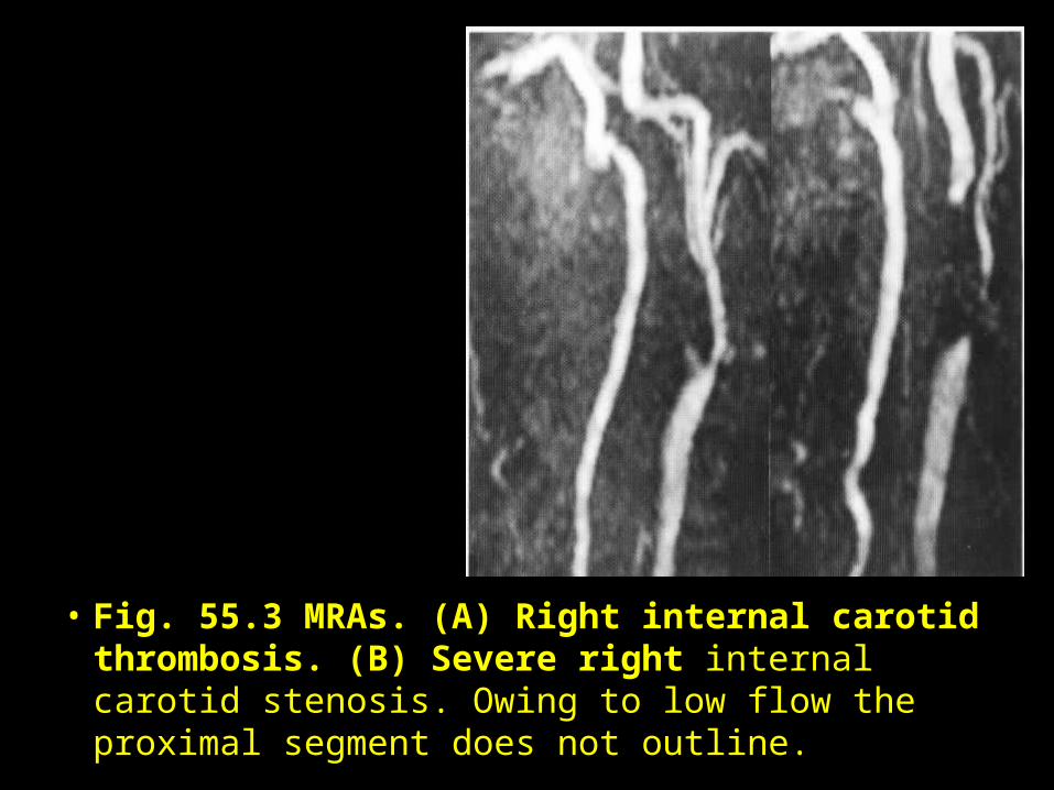
• Fig. 55.3 MRAs. (A) Right internal carotid thrombosis. (B) Severe right internal carotid stenosis. Owing to low flow the proximal segment does not outline.
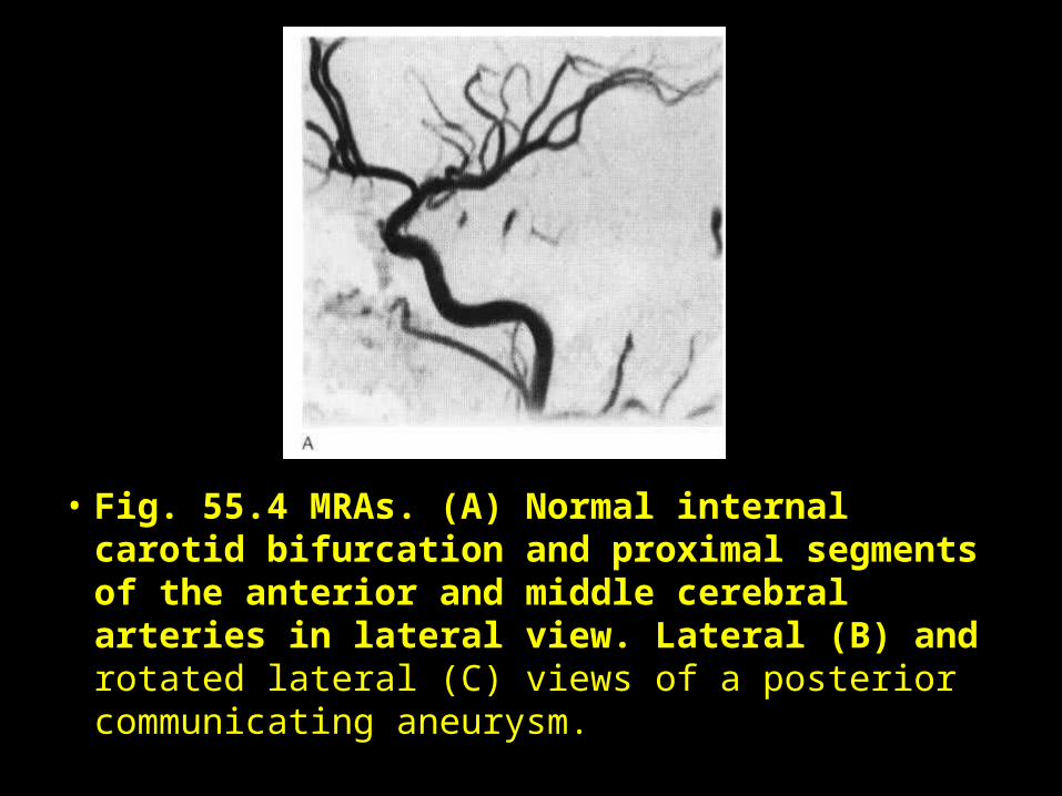
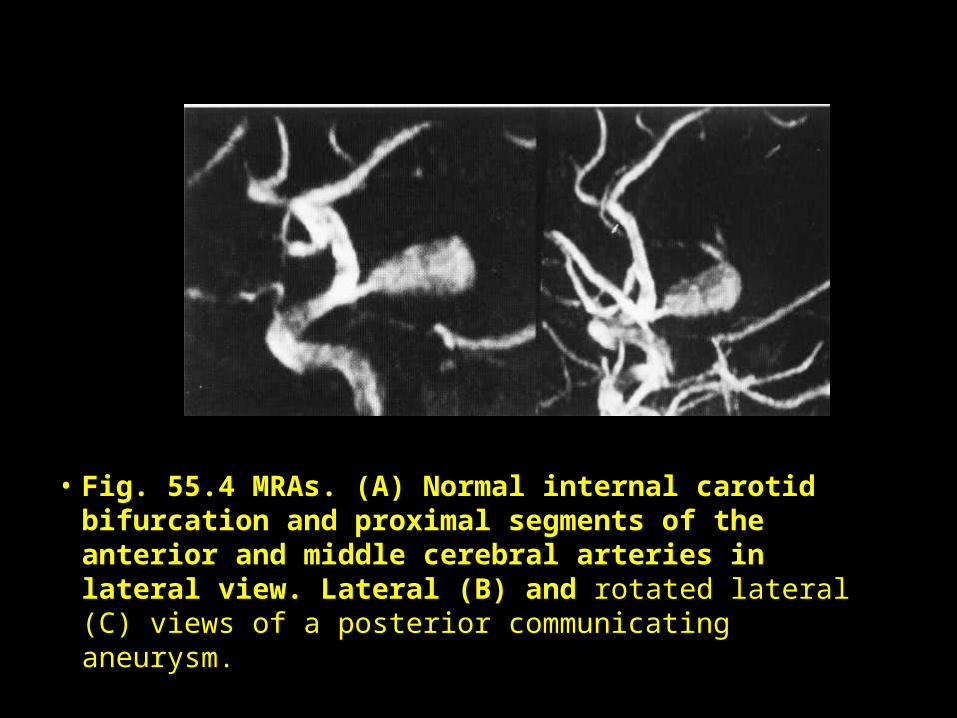
• Fig. 55.4 MRAs. (A) Normal internal carotid bifurcation and proximal segments of the anterior and middle cerebral arteries in lateral view. Lateral (B) and rotated lateral (C) views of a posterior communicating aneurysm.
• Fig. 55.4 MRAs. (A) Normal internal carotid bifurcation and proximal segments of the anterior and middle cerebral arteries in lateral view. Lateral (B) and rotated lateral (C) views of a posterior communicating aneurysm.
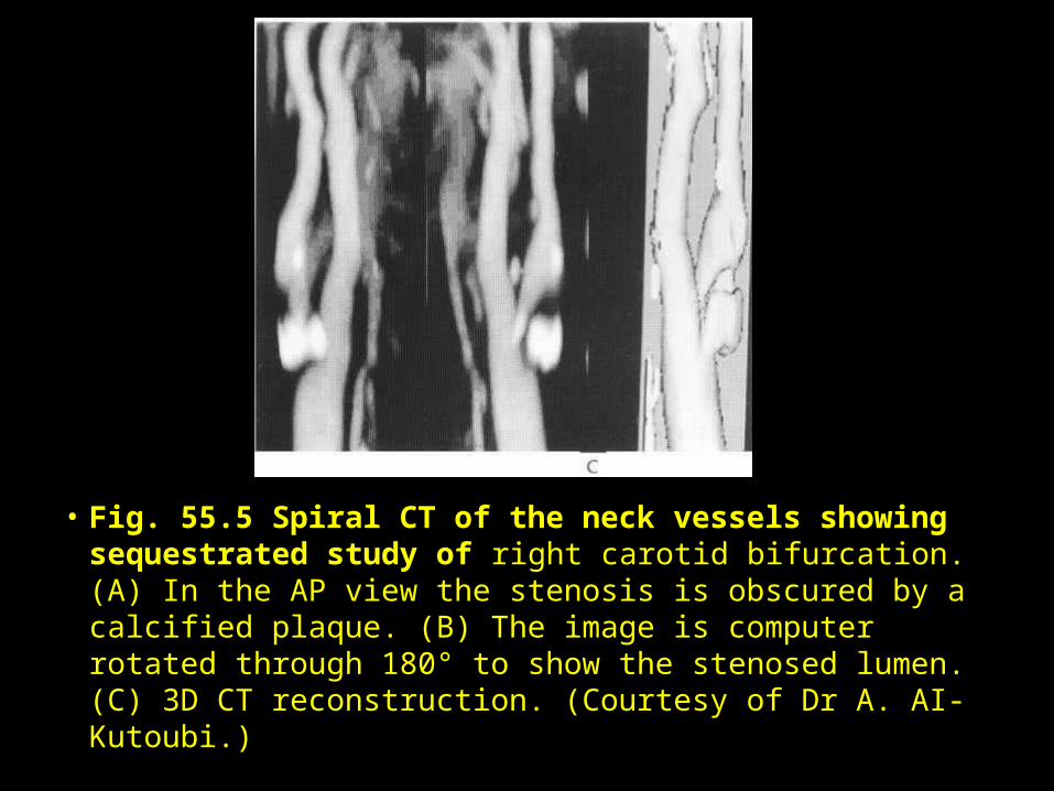
• Fig. 55.5 Spiral CT of the neck vessels showing sequestrated study of right carotid bifurcation. (A) In the AP view the stenosis is obscured by a calcified plaque. (B) The image is computer rotated through 180° to show the stenosed lumen. (C) 3D CT reconstruction. (Courtesy of Dr A. AI-Kutoubi.)
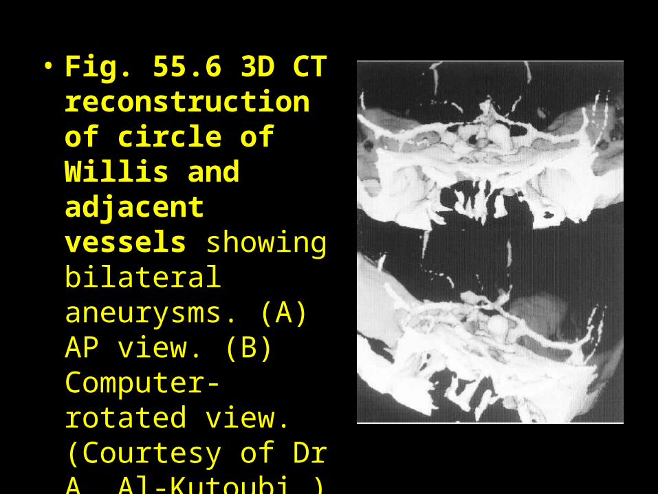
• Fig. 55.6 3D CT reconstruction of circle of Willis and adjacent vessels showing bilateral aneurysms. (A) AP view. (B) Computer-rotated view. (Courtesy of Dr A. Al-Kutoubi.)
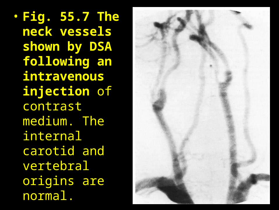
• Fig. 55.7 The neck vessels shown by DSA following an intravenous injection of contrast medium. The internal carotid and vertebral origins are normal.

• Fig. 55.8 DSA study showing the cortical veins, sagittal and lateral sinuses. Note large vein of Trolard and smaller vein of Labbe.
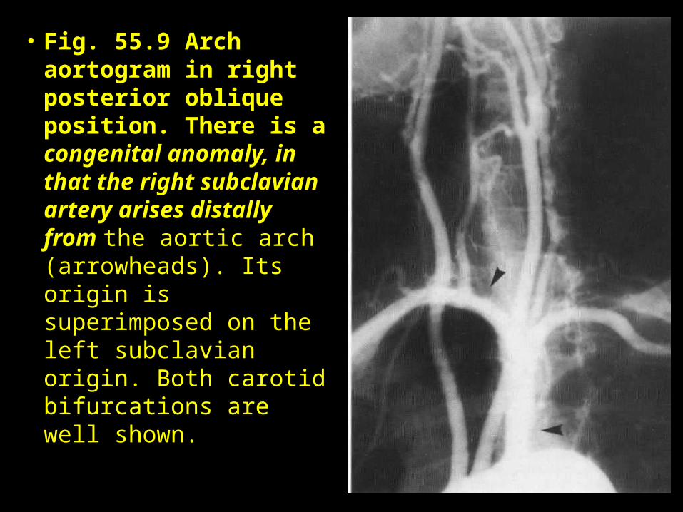
• Fig. 55.9 Arch aortogram in right posterior oblique position. There is a congenital anomaly, in that the right subclavian artery arises distally from the aortic arch (arrowheads). Its origin is superimposed on the left subclavian origin. Both carotid bifurcations are well shown.
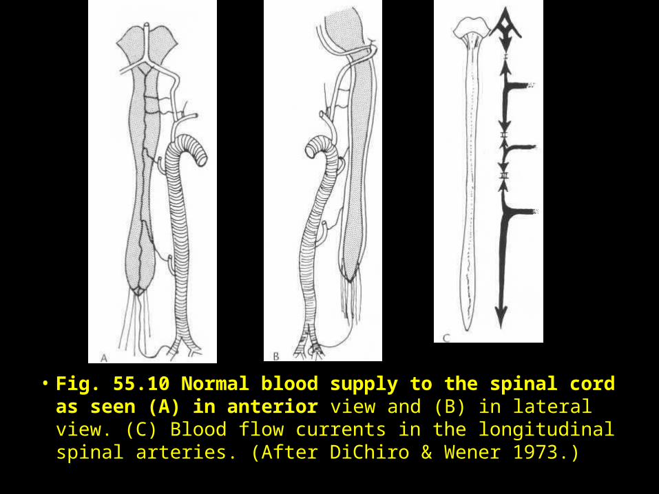
• Fig. 55.10 Normal blood supply to the spinal cord as seen (A) in anterior view and (B) in lateral view. (C) Blood flow currents in the longitudinal spinal arteries. (After DiChiro & Wener 1973.)
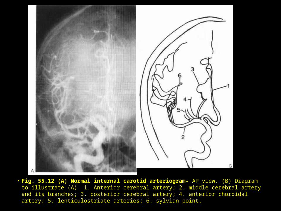
• Fig. 55.12 (A) Normal internal carotid arteriogram- AP view. (B) Diagram to illustrate (A). 1. Anterior cerebral artery; 2. middle cerebral artery and its branches; 3. posterior cerebral artery; 4. anterior choroidal artery; 5. lenticulostriate arteries; 6. sylvian point.
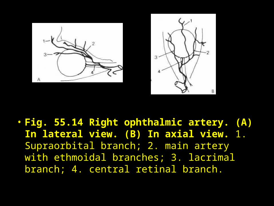
• Fig. 55.14 Right ophthalmic artery. (A) In lateral view. (B) In axial view. 1. Supraorbital branch; 2. main artery with ethmoidal branches; 3. lacrimal branch; 4. central retinal branch.
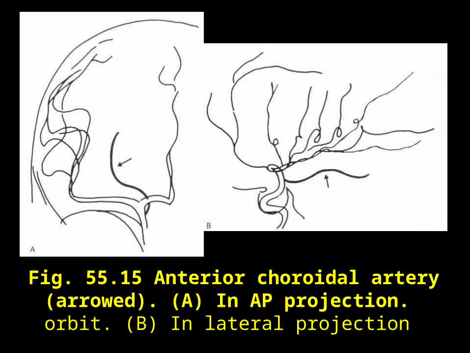
Fig. 55.15 Anterior choroidal artery (arrowed). (A) In AP projection. orbit. (B) In lateral projection
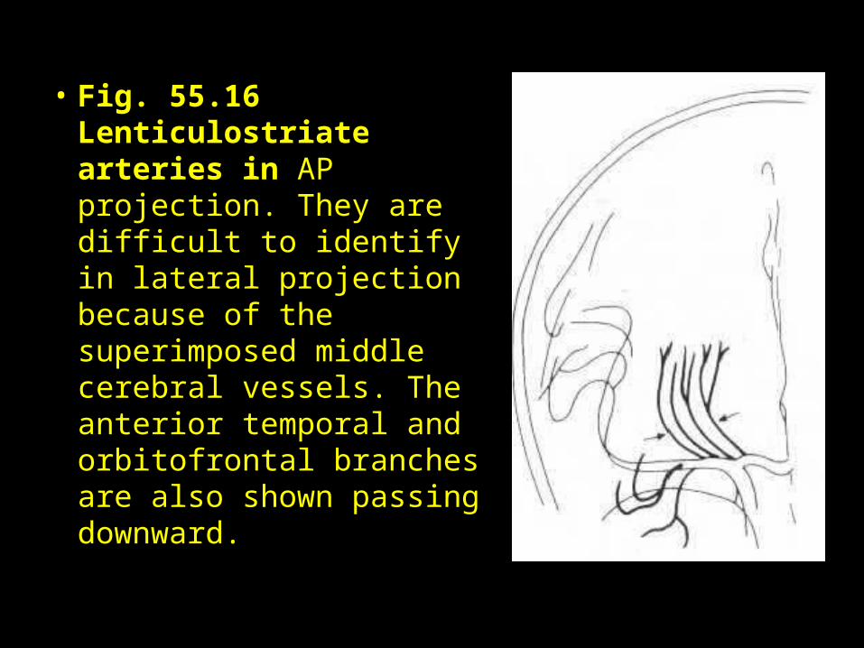
• Fig. 55.16 Lenticulostriate arteries in AP projection. They are difficult to identify in lateral projection because of the superimposed middle cerebral vessels. The anterior temporal and orbitofrontal branches are also shown passing downward.
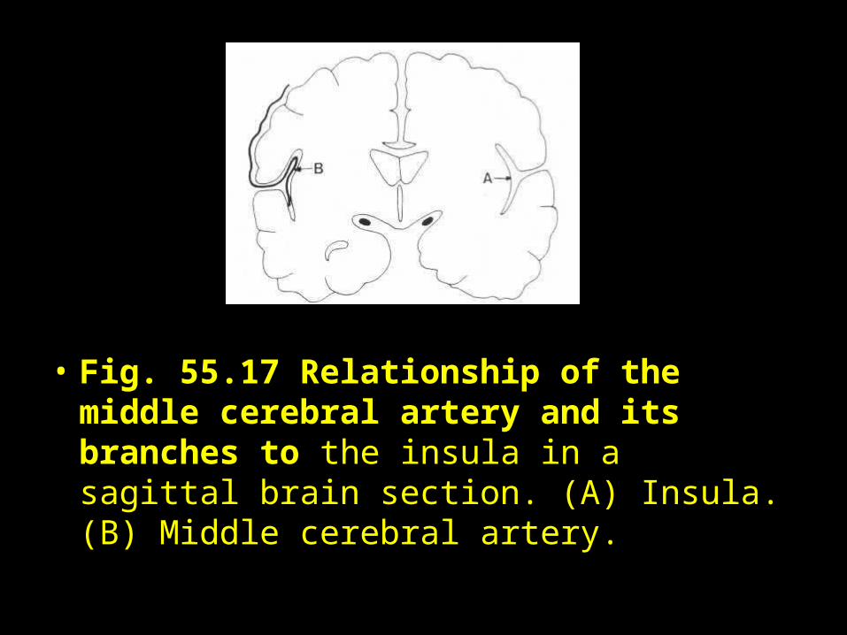
• Fig. 55.17 Relationship of the middle cerebral artery and its branches to the insula in a sagittal brain section. (A) Insula. (B) Middle cerebral artery.
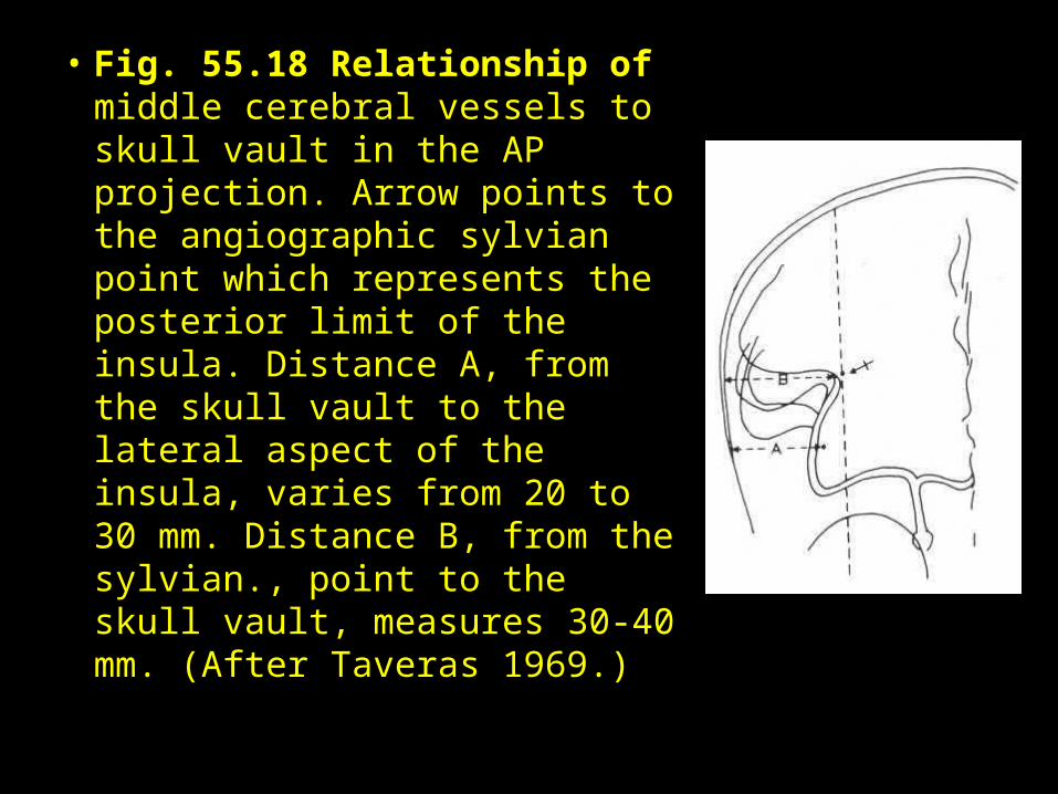
• Fig. 55.18 Relationship of middle cerebral vessels to skull vault in the AP projection. Arrow points to the angiographic sylvian point which represents the posterior limit of the insula. Distance A, from the skull vault to the lateral aspect of the insula, varies from 20 to 30 mm. Distance B, from the sylvian., point to the skull vault, measures 30-40 mm. (After Taveras 1969.)
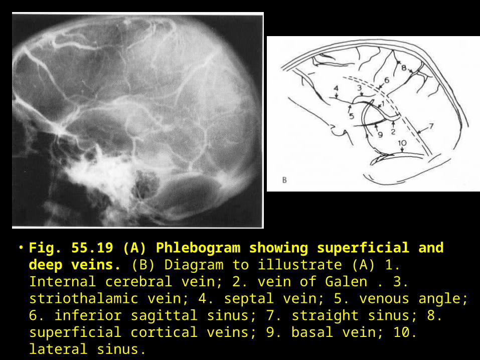
• Fig. 55.19 (A) Phlebogram showing superficial and deep veins. (B) Diagram to illustrate (A) 1. Internal cerebral vein; 2. vein of Galen . 3. striothalamic vein; 4. septal vein; 5. venous angle; 6. inferior sagittal sinus; 7. straight sinus; 8. superficial cortical veins; 9. basal vein; 10. lateral sinus.
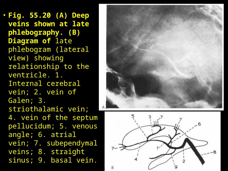
• Fig. 55.20 (A) Deep veins shown at late phlebography. (B) Diagram of late phlebogram (lateral view) showing relationship to the ventricle. 1. Internal cerebral vein; 2. vein of Galen; 3. striothalamic vein; 4. vein of the septum pellucidum; 5. venous angle; 6. atrial vein; 7. subependymal veins; 8. straight sinus; 9. basal vein.
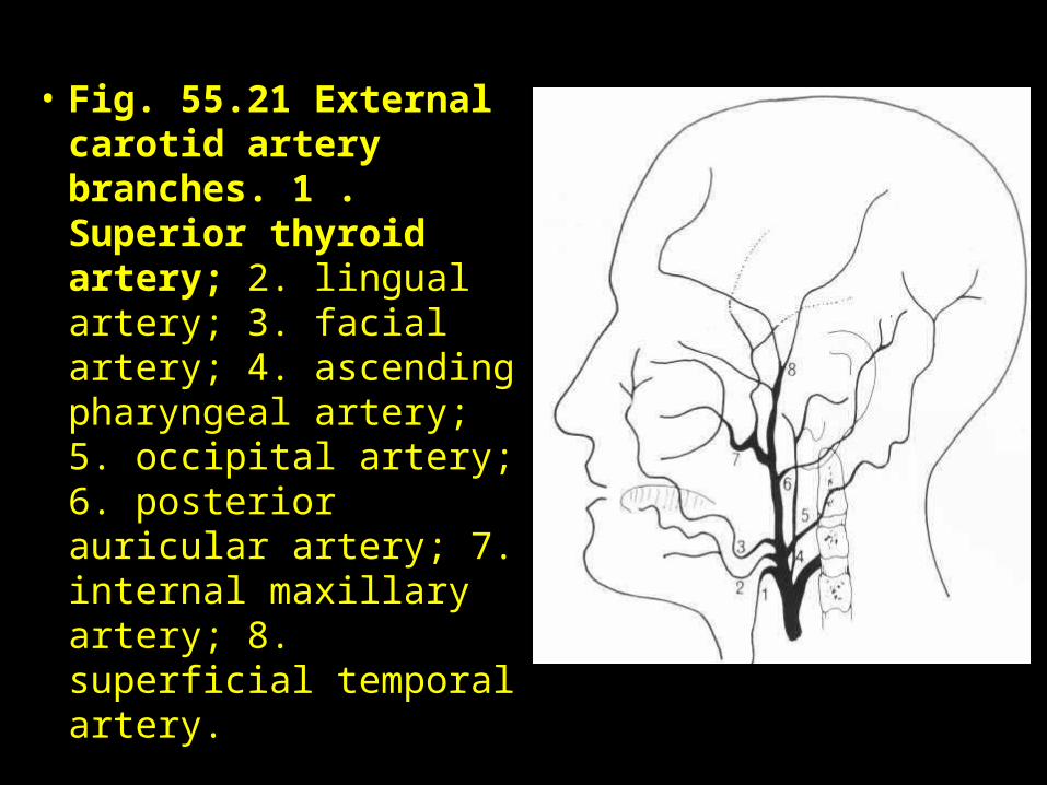
• Fig. 55.21 External carotid artery branches. 1 . Superior thyroid artery; 2. lingual artery; 3. facial artery; 4. ascending pharyngeal artery; 5. occipital artery; 6. posterior auricular artery; 7. internal maxillary artery; 8. superficial temporal artery.
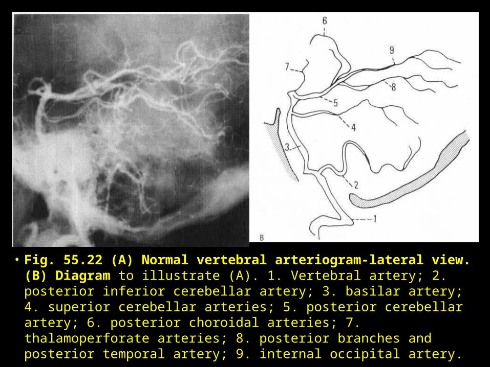
• Fig. 55.22 (A) Normal vertebral arteriogram-lateral view. (B) Diagram to illustrate (A). 1. Vertebral artery; 2. posterior inferior cerebellar artery; 3. basilar artery; 4. superior cerebellar arteries; 5. posterior cerebellar artery; 6. posterior choroidal arteries; 7. thalamoperforate arteries; 8. posterior branches and posterior temporal artery; 9. internal occipital artery.
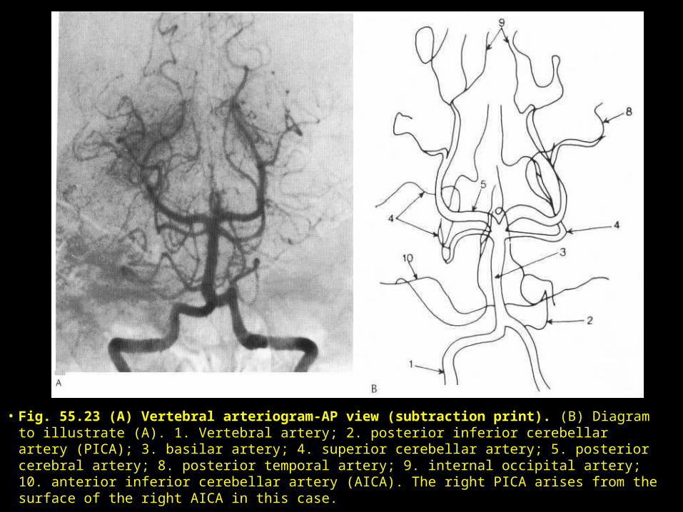
• Fig. 55.23 (A) Vertebral arteriogram-AP view (subtraction print). (B) Diagram to illustrate (A). 1. Vertebral artery; 2. posterior inferior cerebellar artery (PICA); 3. basilar artery; 4. superior cerebellar artery; 5. posterior cerebral artery; 8. posterior temporal artery; 9. internal occipital artery; 10. anterior inferior cerebellar artery (AICA). The right PICA arises from the surface of the right AICA in this case.
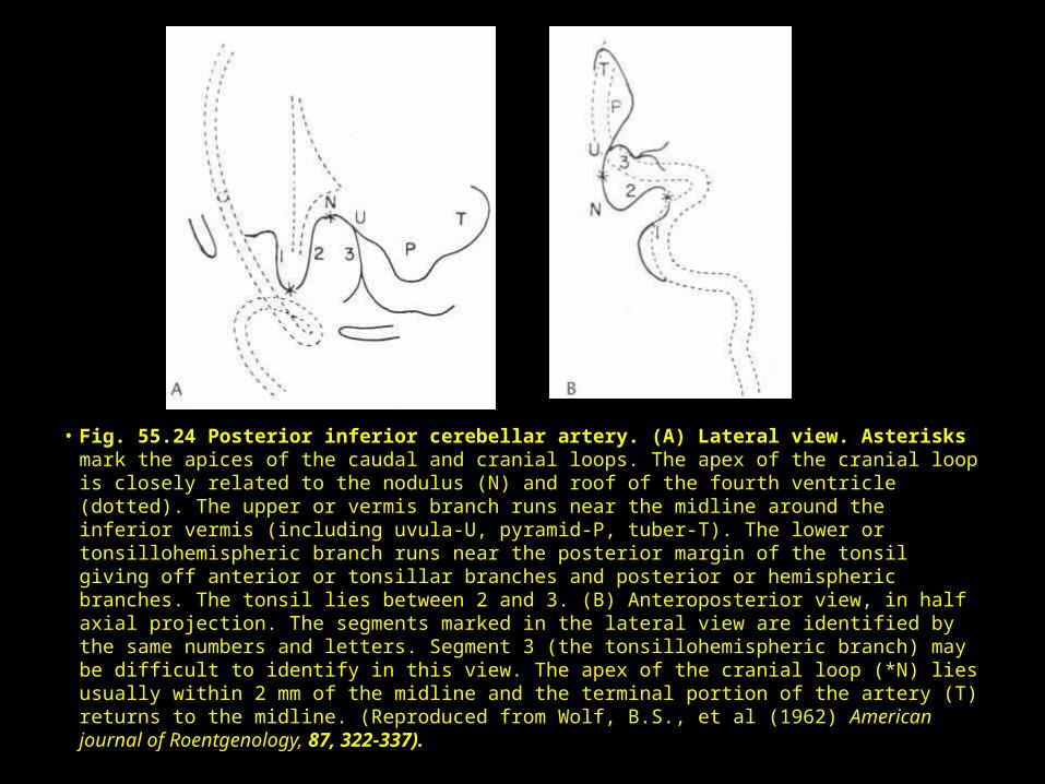
• Fig. 55.24 Posterior inferior cerebellar artery. (A) Lateral view. Asterisks mark the apices of the caudal and cranial loops. The apex of the cranial loop is closely related to the nodulus (N) and roof of the fourth ventricle (dotted). The upper or vermis branch runs near the midline around the inferior vermis (including uvula-U, pyramid-P, tuber-T). The lower or tonsillohemispheric branch runs near the posterior margin of the tonsil giving off anterior or tonsillar branches and posterior or hemispheric branches. The tonsil lies between 2 and 3. (B) Anteroposterior view, in half axial projection. The segments marked in the lateral view are identified by the same numbers and letters. Segment 3 (the tonsillohemispheric branch) may be difficult to identify in this view. The apex of the cranial loop (*N) lies usually within 2 mm of the midline and the terminal portion of the artery (T) returns to the midline. (Reproduced from Wolf, B.S., et al (1962) American journal of Roentgenology, 87, 322-337).
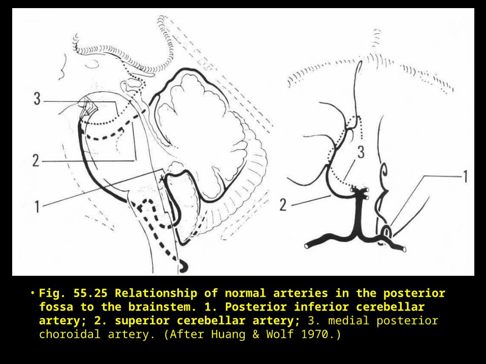
• Fig. 55.25 Relationship of normal arteries in the posterior fossa to the brainstem. 1. Posterior inferior cerebellar artery; 2. superior cerebellar artery; 3. medial posterior choroidal artery. (After Huang & Wolf 1970.)
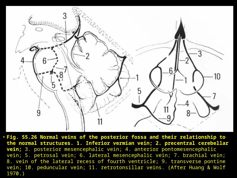
• Fig. 55.26 Normal veins of the posterior fossa and their relationship to the normal structures. 1. Inferior vermian vein; 2. precentral cerebellar vein; 3. posterior mesencephalic vein; 4. anterior pontomesencephalic vein; 5. petrosal vein; 6. lateral mesencephalic vein; 7. brachial vein; 8. vein of the lateral recess of fourth ventricle; 9. transverse pontine vein; 10. peduncular vein; 11. retrotonsillar veins. (After Huang & Wolf 1970.)
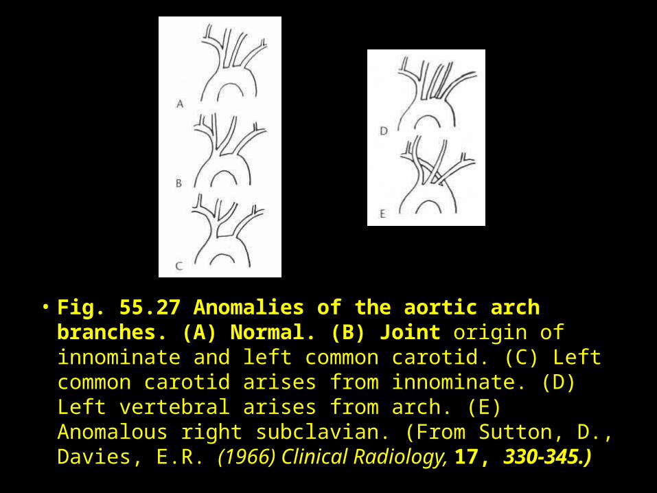
• Fig. 55.27 Anomalies of the aortic arch branches. (A) Normal. (B) Joint origin of innominate and left common carotid. (C) Left common carotid arises from innominate. (D) Left vertebral arises from arch. (E) Anomalous right subclavian. (From Sutton, D., Davies, E.R. (1966) Clinical Radiology, 17, 330-345.)
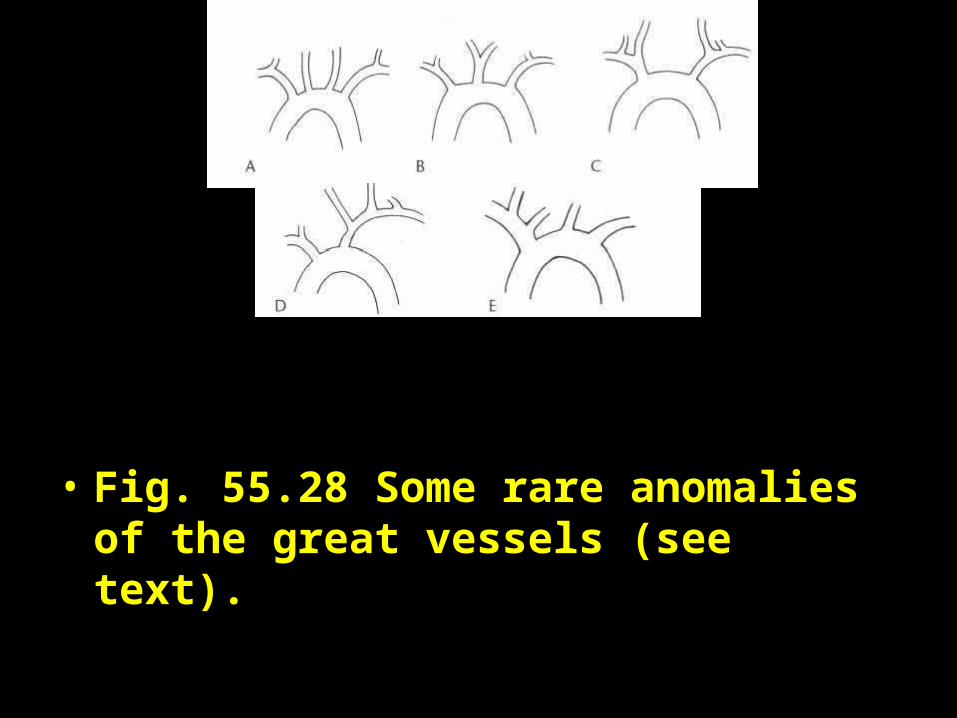
• Fig. 55.28 Some rare anomalies of the great vessels (see text).
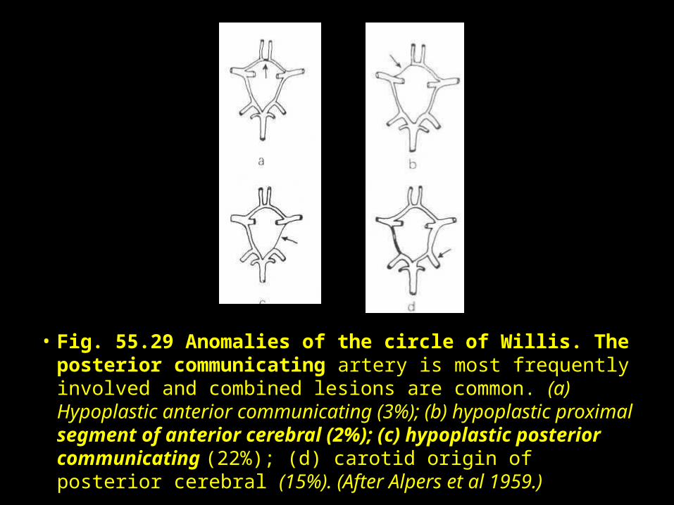
• Fig. 55.29 Anomalies of the circle of Willis. The posterior communicating artery is most frequently involved and combined lesions are common. (a) Hypoplastic anterior communicating (3%); (b) hypoplastic proximal segment of anterior cerebral (2%); (c) hypoplastic posterior communicating (22%); (d) carotid origin of posterior cerebral (15%). (After Alpers et al 1959.)
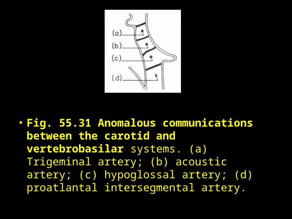
• Fig. 55.31 Anomalous communications between the carotid and vertebrobasilar systems. (a) Trigeminal artery; (b) acoustic artery; (c) hypoglossal artery; (d) proatlantal intersegmental artery.

• Fig. 30: Anomalous carotid-basilar anastomosis (arrow). This is an example of the trigeminal artery. Lateral view.
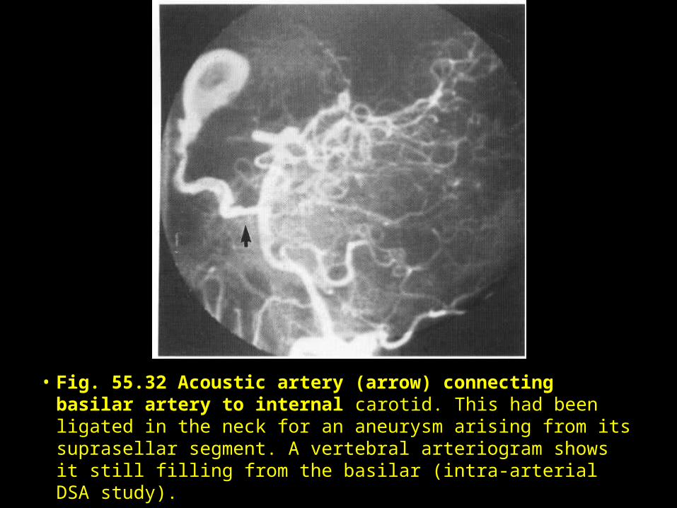
• Fig. 55.32 Acoustic artery (arrow) connecting basilar artery to internal carotid. This had been ligated in the neck for an aneurysm arising from its suprasellar segment. A vertebral arteriogram shows it still filling from the basilar (intra-arterial DSA study).
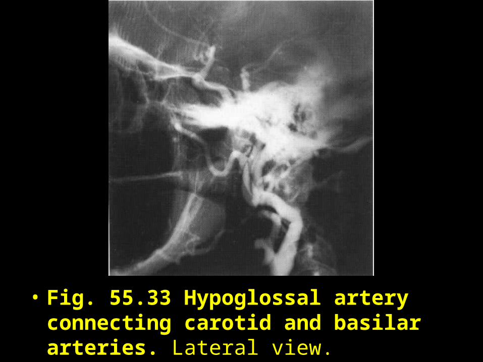
• Fig. 55.33 Hypoglossal artery connecting carotid and basilar arteries. Lateral view.
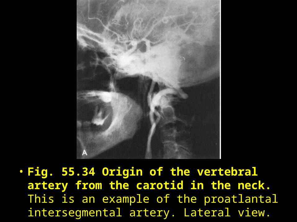
• Fig. 55.34 Origin of the vertebral artery from the carotid in the neck. This is an example of the proatlantal intersegmental artery. Lateral view.
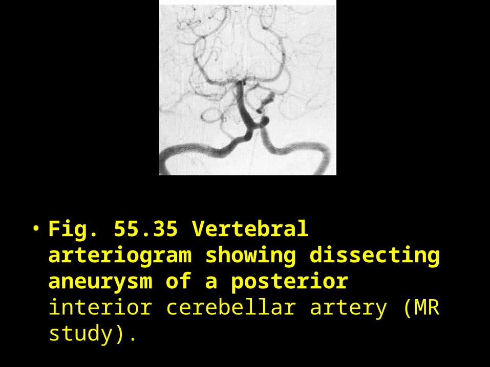
• Fig. 55.35 Vertebral arteriogram showing dissecting aneurysm of a posterior interior cerebellar artery (MR study).
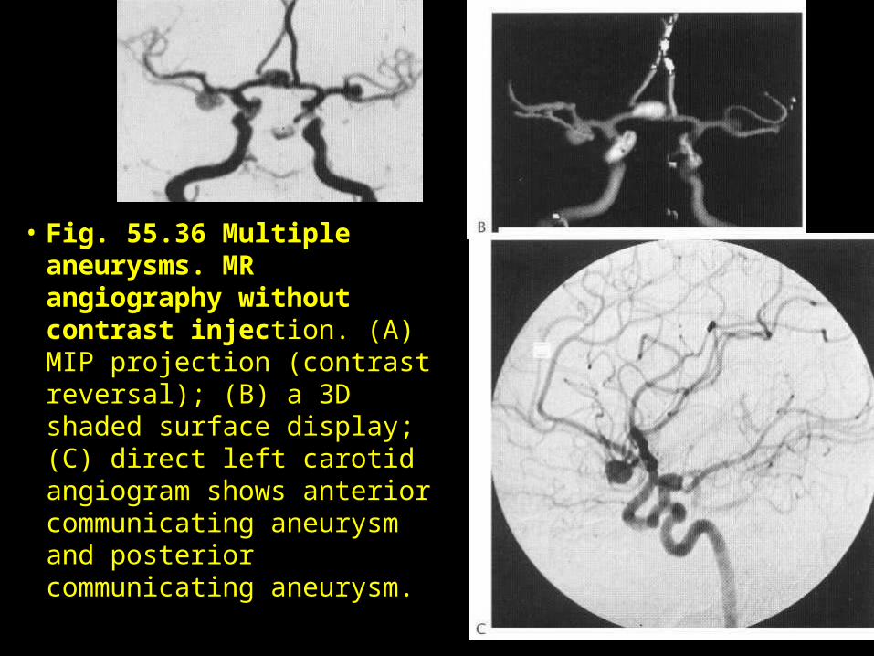
• Fig. 55.36 Multiple aneurysms. MR angiography without contrast injection. (A) MIP projection (contrast reversal); (B) a 3D shaded surface display; (C) direct left carotid angiogram shows anterior communicating aneurysm and posterior communicating aneurysm.
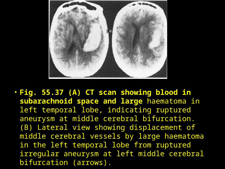
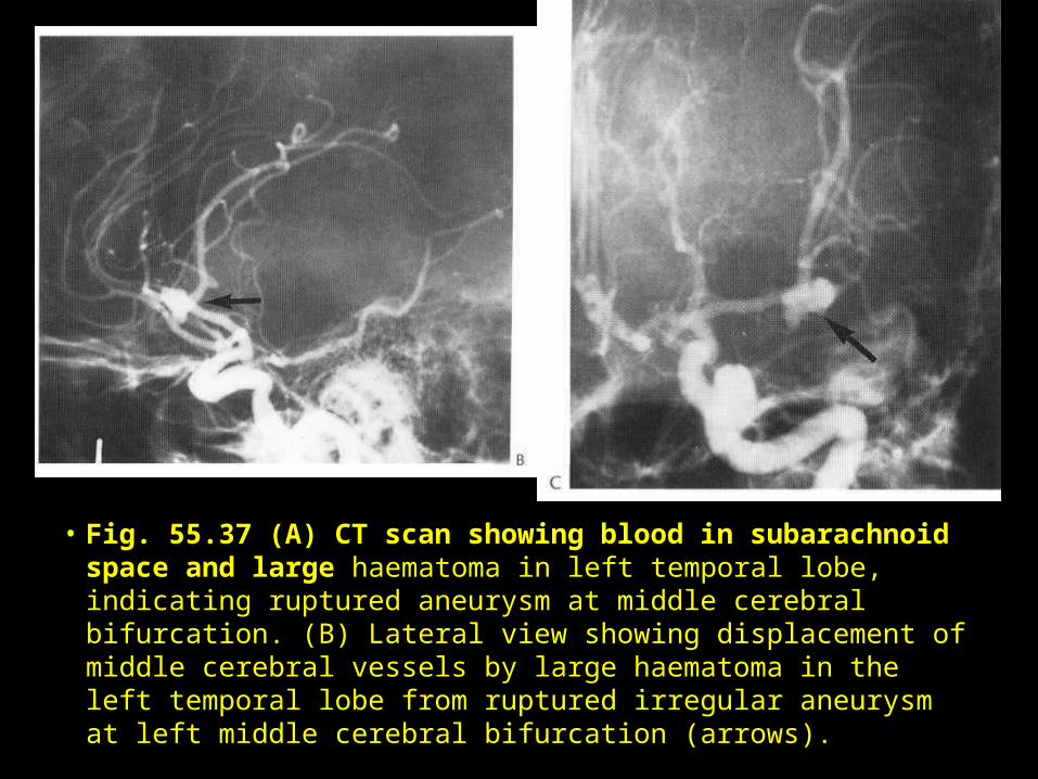
• Fig. 55.37 (A) CT scan showing blood in subarachnoid space and large haematoma in left temporal lobe, indicating ruptured aneurysm at middle cerebral bifurcation. (B) Lateral view showing displacement of middle cerebral vessels by large haematoma in the left temporal lobe from ruptured irregular aneurysm at left middle cerebral bifurcation (arrows).
• Fig. 55.37 (A) CT scan showing blood in subarachnoid space and large haematoma in left temporal lobe, indicating ruptured aneurysm at middle cerebral bifurcation. (B) Lateral view showing displacement of middle cerebral vessels by large haematoma in the left temporal lobe from ruptured irregular aneurysm at left middle cerebral bifurcation (arrows).
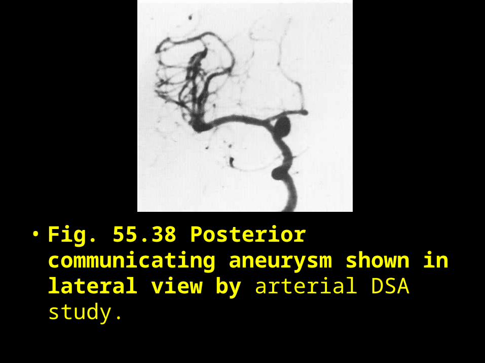
• Fig. 55.38 Posterior communicating aneurysm shown in lateral view by arterial DSA study.
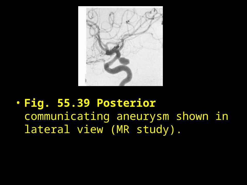
• Fig. 55.39 Posterior communicating aneurysm shown in lateral view (MR study).
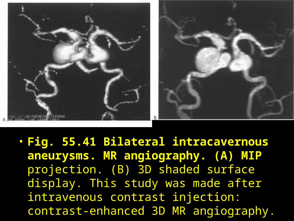
• Fig. 55.41 Bilateral intracavernous aneurysms. MR angiography. (A) MIP projection. (B) 3D shaded surface display. This study was made after intravenous contrast injection: contrast-enhanced 3D MR angiography.
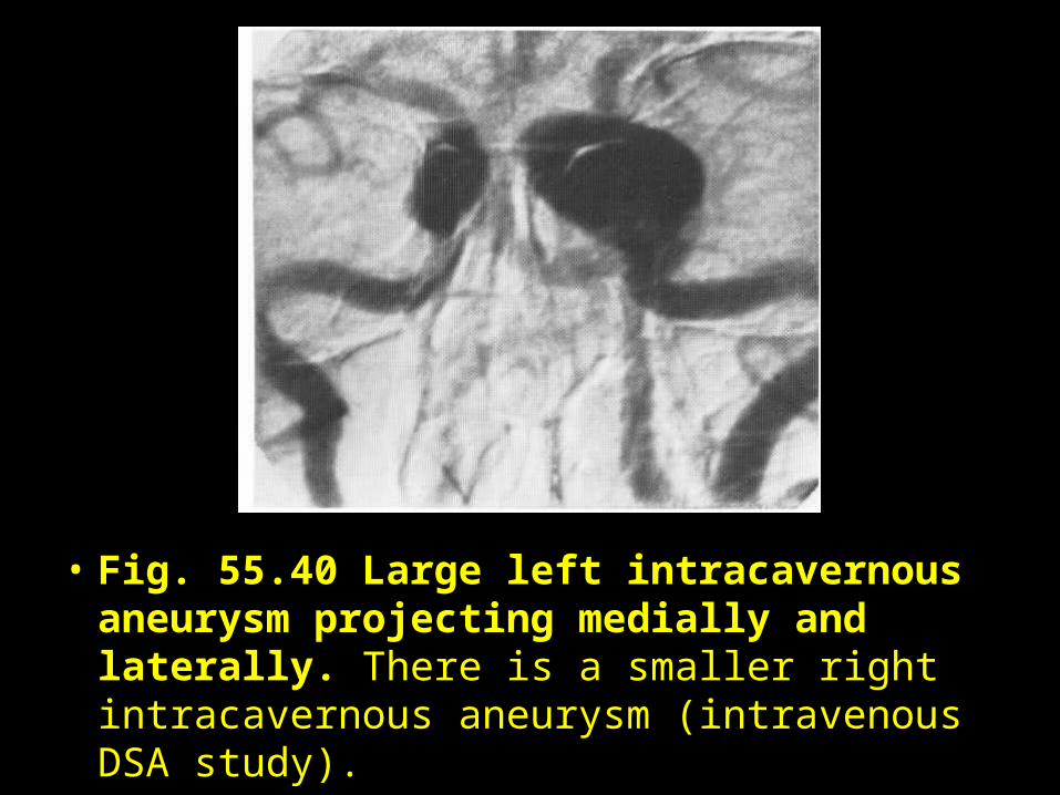
• Fig. 55.40 Large left intracavernous aneurysm projecting medially and laterally. There is a smaller right intracavernous aneurysm (intravenous DSA study).

• Fig. 55.42 Huge intra- and suprasellar aneurysm of right internal carotid. (A) Lateral view. (B,C) CT cuts through anterior clinoids and suprasellar cisterns, respectively, show bony erosions (arrow) and rounded mass of aneurysm (arrow). (D) Post-enhancement CT shows the aneurysm clearly.

• Fig. 55.42 Huge intra- and suprasellar aneurysm of right internal carotid. (A) Lateral view. (B,C) CT cuts through anterior clinoids and suprasellar cisterns, respectively, show bony erosions (arrow) and rounded mass of aneurysm (arrow). (D) Post-enhancement CT shows the aneurysm clearly.
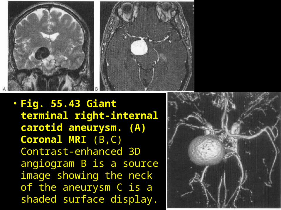
• Fig. 55.43 Giant terminal right-internal carotid aneurysm. (A) Coronal MRI (B,C) Contrast-enhanced 3D angiogram B is a source image showing the neck of the aneurysm C is a shaded surface display.
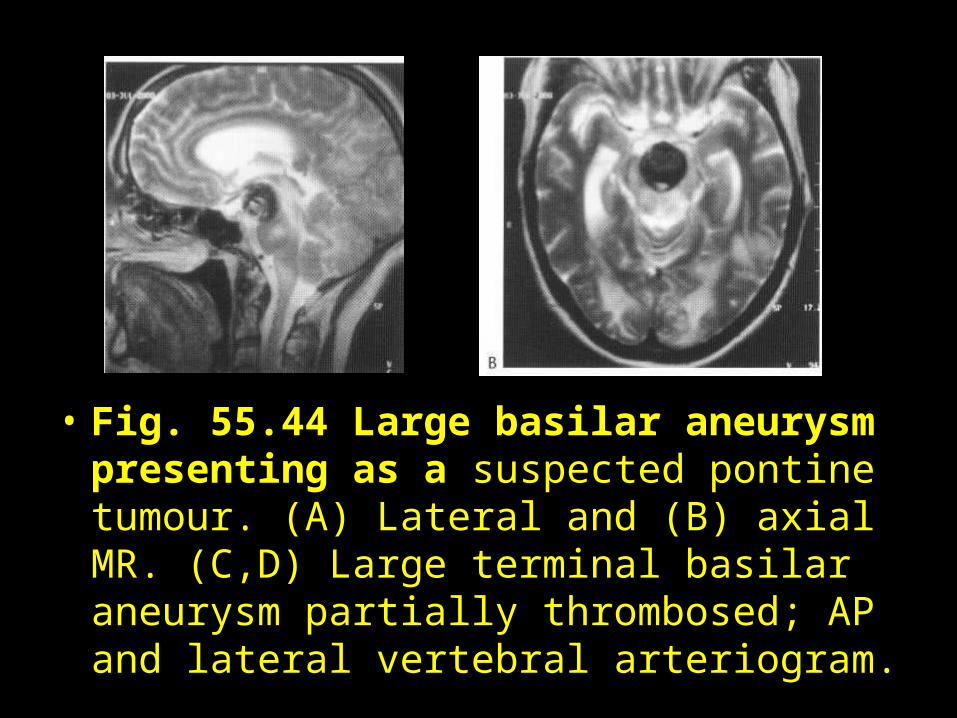
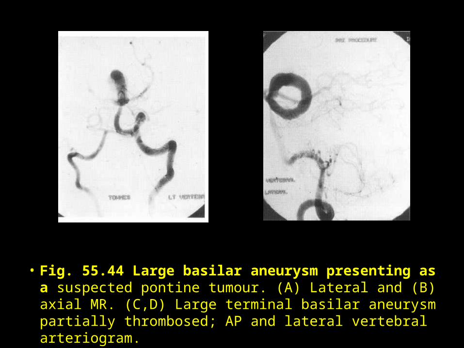
• Fig. 55.44 Large basilar aneurysm presenting as a suspected pontine tumour. (A) Lateral and (B) axial MR. (C,D) Large terminal basilar aneurysm partially thrombosed; AP and lateral vertebral arteriogram.
• Fig. 55.44 Large basilar aneurysm presenting as a suspected pontine tumour. (A) Lateral and (B) axial MR. (C,D) Large terminal basilar aneurysm partially thrombosed; AP and lateral vertebral arteriogram.
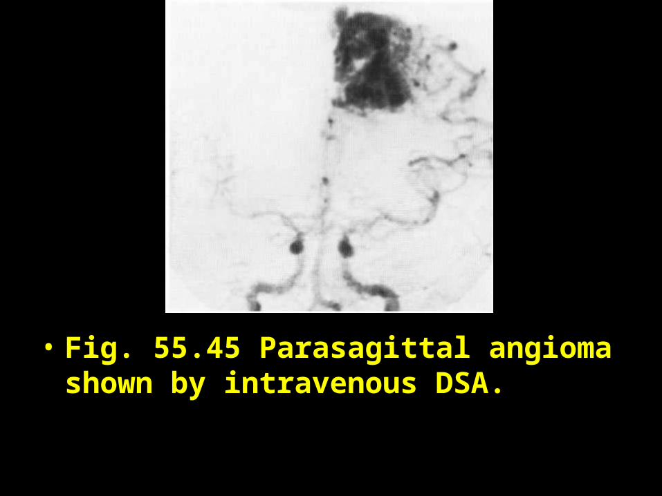
• Fig. 55.45 Parasagittal angioma shown by intravenous DSA.
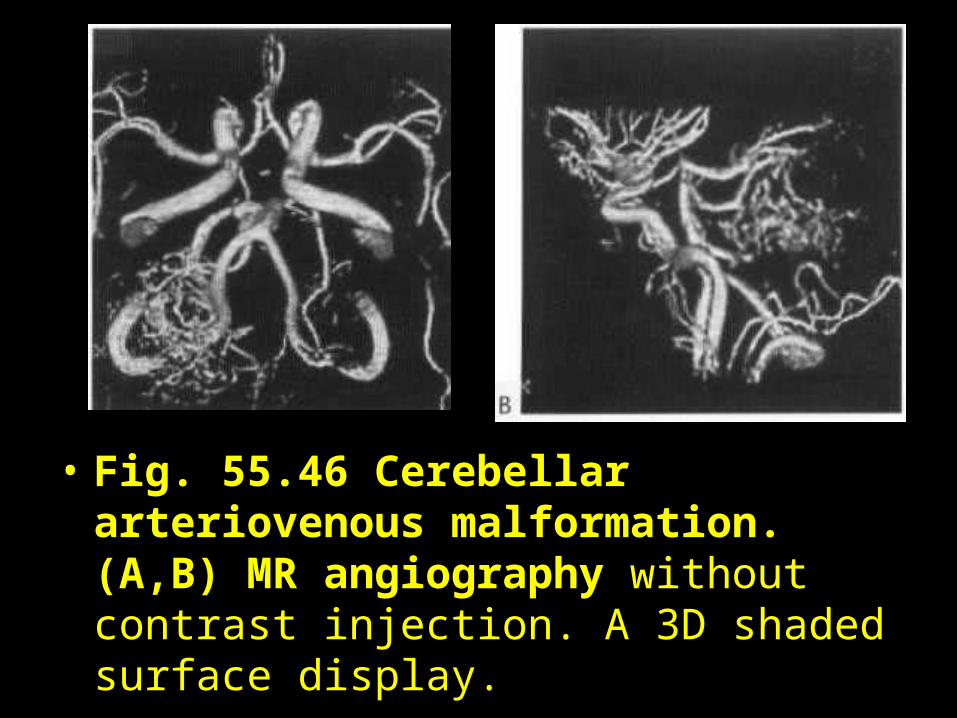
• Fig. 55.46 Cerebellar arteriovenous malformation. (A,B) MR angiography without contrast injection. A 3D shaded surface display.
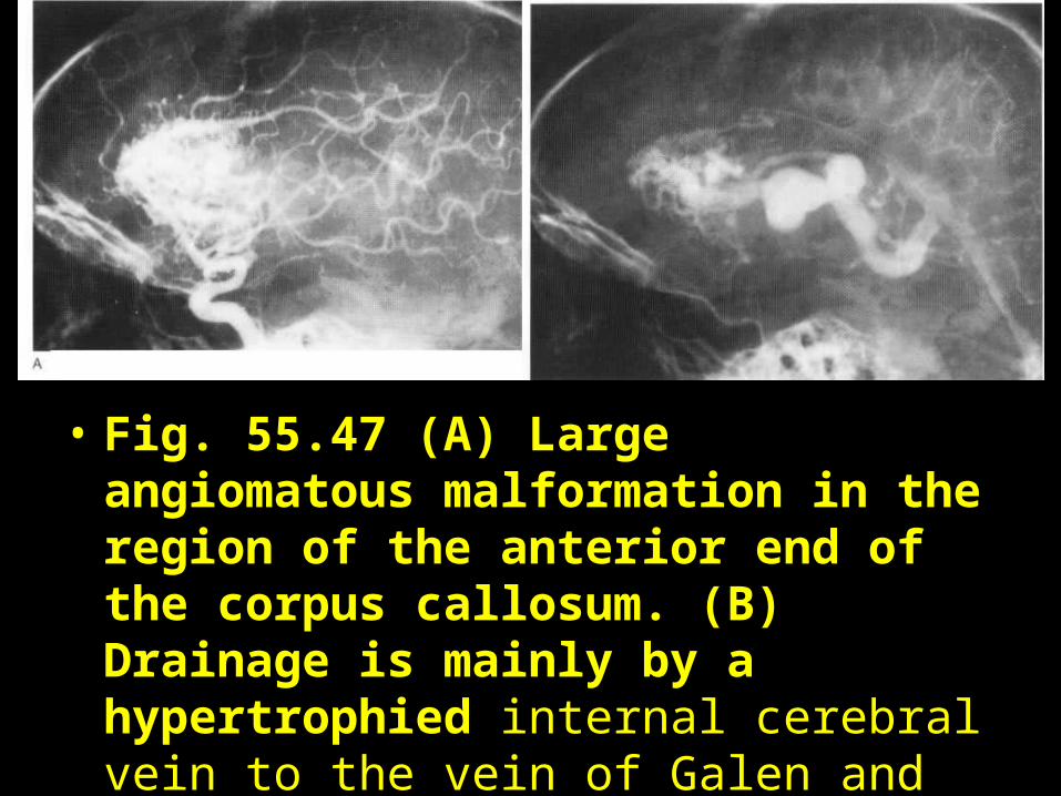
• Fig. 55.47 (A) Large angiomatous malformation in the region of the anterior end of the corpus callosum. (B) Drainage is mainly by a hypertrophied internal cerebral vein to the vein of Galen and straight sinus.
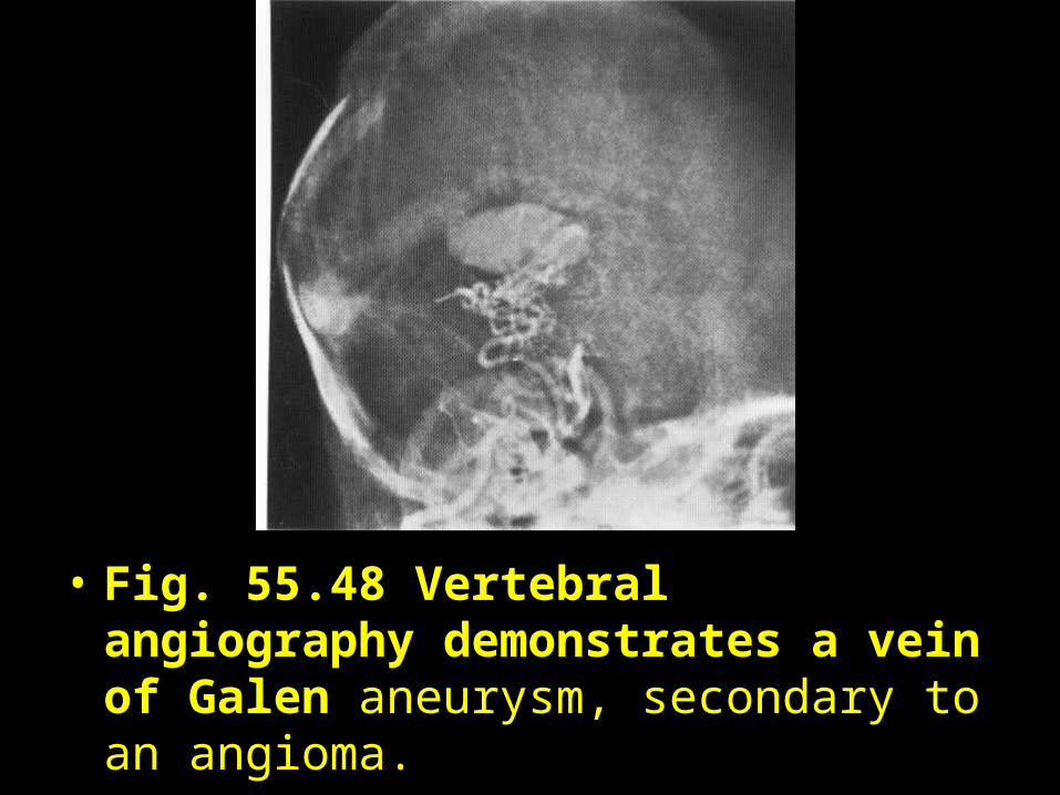
• Fig. 55.48 Vertebral angiography demonstrates a vein of Galen aneurysm, secondary to an angioma.
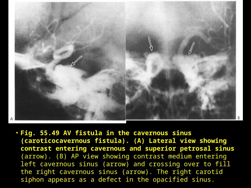
• Fig. 55.49 AV fistula in the cavernous sinus (caroticocavernous fistula). (A) Lateral view showing contrast entering cavernous and superior petrosal sinus (arrow). (B) AP view showing contrast medium entering left cavernous sinus (arrow) and crossing over to fill the right cavernous sinus (arrow). The right carotid siphon appears as a defect in the opacified sinus.
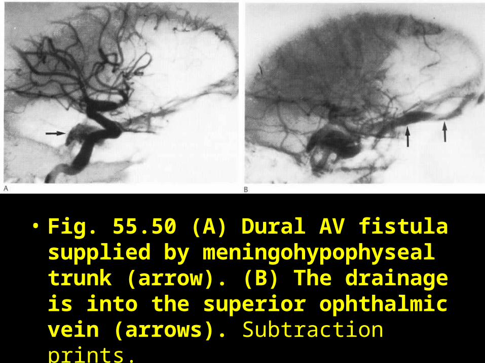
• Fig. 55.50 (A) Dural AV fistula supplied by meningohypophyseal trunk (arrow). (B) The drainage is into the superior ophthalmic vein (arrows). Subtraction prints.
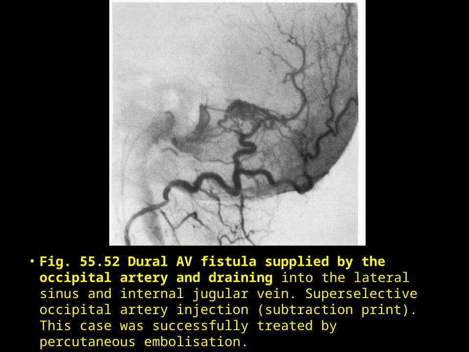
• Fig. 55.52 Dural AV fistula supplied by the occipital artery and draining into the lateral sinus and internal jugular vein. Superselective occipital artery injection (subtraction print). This case was successfully treated by percutaneous embolisation.
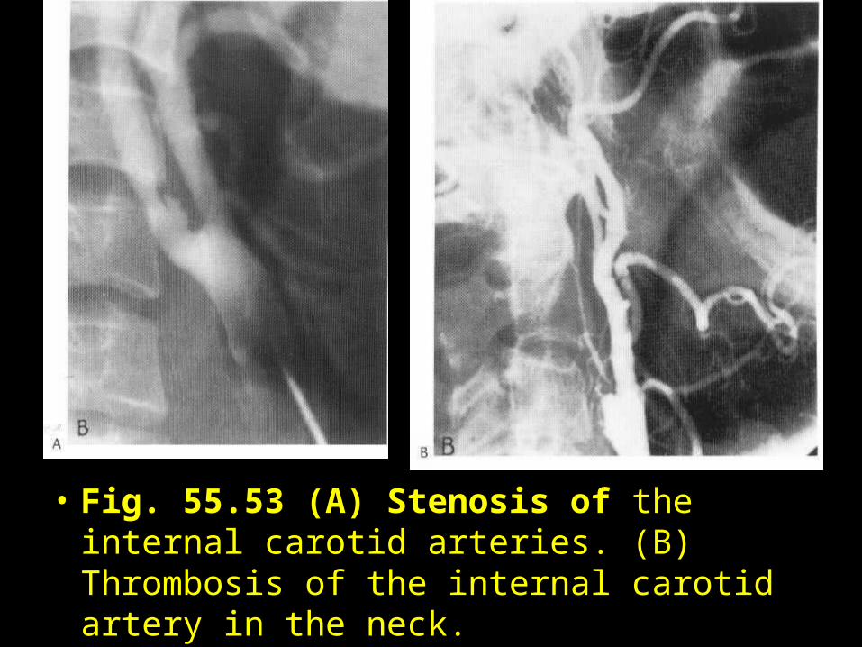
• Fig. 55.53 (A) Stenosis of the internal carotid arteries. (B) Thrombosis of the internal carotid artery in the neck.
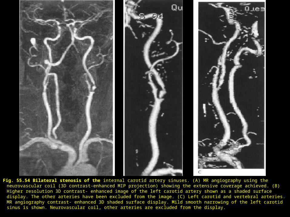
Fig. 55.54 Bilateral stenosis of the internal carotid artery sinuses. (A) MR angiography using the neurovascular coil (3D contrast-enhanced MIP projection) showing the extensive coverage achieved. (B) Higher resolution 3D contrast- enhanced image of the left carotid artery shown as a shaded surface display. The other arteries have been excluded from the image. (C) Left carotid and vertebral arteries. MR angiography contrast- enhanced 3D shaded surface display. Mild smooth narrowing of the left carotid sinus is shown. Neurovascular coil, other arteries are excluded from the display.
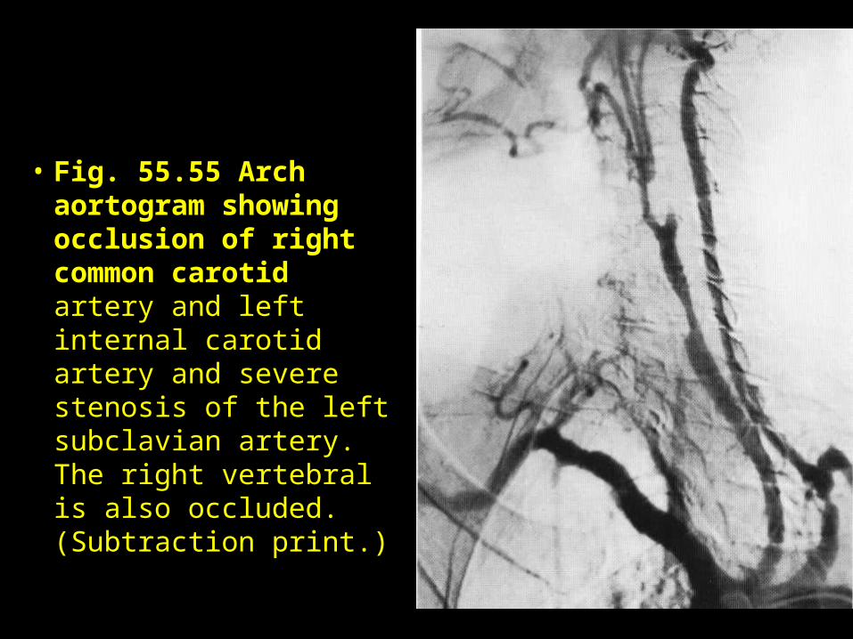
• Fig. 55.55 Arch aortogram showing occlusion of right common carotid artery and left internal carotid artery and severe stenosis of the left subclavian artery. The right vertebral is also occluded. (Subtraction print.)
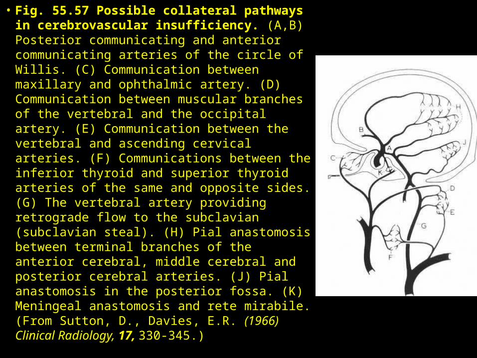
• Fig. 55.57 Possible collateral pathways in cerebrovascular insufficiency. (A,B) Posterior communicating and anterior communicating arteries of the circle of Willis. (C) Communication between maxillary and ophthalmic artery. (D) Communication between muscular branches of the vertebral and the occipital artery. (E) Communication between the vertebral and ascending cervical arteries. (F) Communications between the inferior thyroid and superior thyroid arteries of the same and opposite sides. (G) The vertebral artery providing retrograde flow to the subclavian (subclavian steal). (H) Pial anastomosis between terminal branches of the anterior cerebral, middle cerebral and posterior cerebral arteries. (J) Pial anastomosis in the posterior fossa. (K) Meningeal anastomosis and rete mirabile. (From Sutton, D., Davies, E.R. (1966) Clinical Radiology, 17, 330-345.)
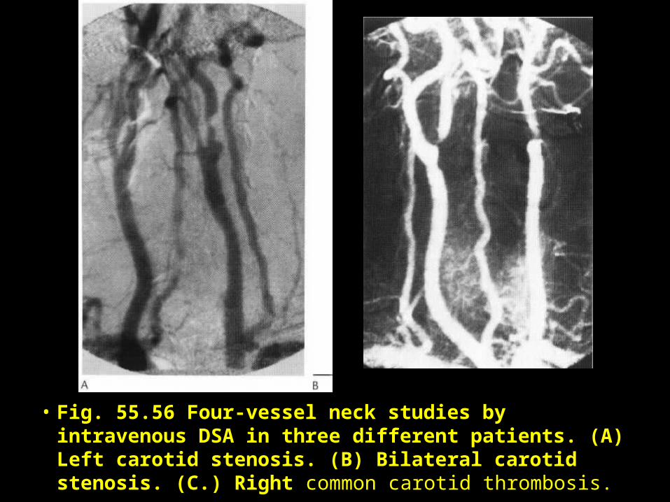
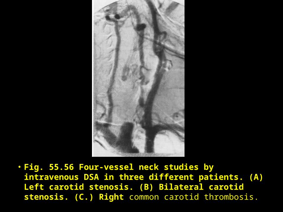
• Fig. 55.56 Four-vessel neck studies by intravenous DSA in three different patients. (A) Left carotid stenosis. (B) Bilateral carotid stenosis. (C.) Right common carotid thrombosis.
• Fig. 55.56 Four-vessel neck studies by intravenous DSA in three different patients. (A) Left carotid stenosis. (B) Bilateral carotid stenosis. (C.) Right common carotid thrombosis.
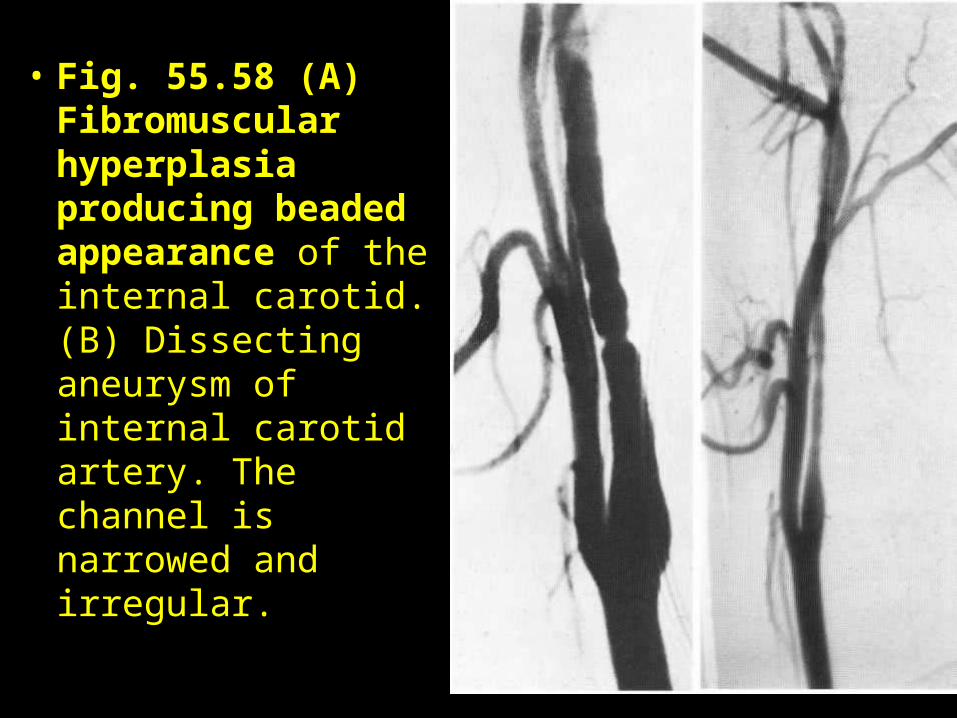
• Fig. 55.58 (A) Fibromuscular hyperplasia producing beaded appearance of the internal carotid. (B) Dissecting aneurysm of internal carotid artery. The channel is narrowed and irregular.
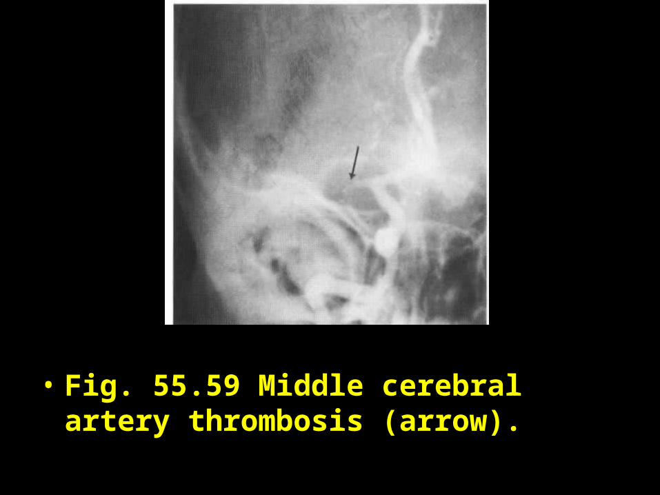
• Fig. 55.59 Middle cerebral artery thrombosis (arrow).