5421 5425.output
32
* GB785829 (A) Description: GB785829 (A) ? 1957-11-06 Improvements in or relating to machines for broadcasting seed, fertilizer and other granular or powdered materials Description of GB785829 (A) COMPLETE SPECIFICATION Improvements in or relating to Machines for Broadcasting Seed, Fertilizer and other Granular or Powdered Materials I, WILLIAM THOMAS TEAGLE, of Blackwater, Truro, Cornwall, a British Subject, do hereby declare the invention, for which I pray that a patent may be granted to me and the method by which it is to be performed, to be particularly described in and by the following statement :- This invention relates to machines for broadcasting seed, fertilizer and other granular or powdered materials, and has specific reference to machines of the kind wherein the material is carried in a hopper from which it is discharged through an outlet at the base of the hopper onto a rotary distributor that rotates about a vertical or substantially vertical axis and ejects the material onto the ground by centrifugal force. The object of the invention is to provide in a machine of the above kind improved means for enabling the distribution of the material to be confined to an arc of variable spread and direction, that is direction in a radial sense relative to the distributor and for varying the rate at which the material is discharged from the hopper onto the distributor and therefore the rate or intensity of distribution over a given arc. These adjustments are used to avoid unevenness of distribution due to variations in the character of the material being distributed, such as differences in weight or density, and in the speed of the tractor or other vehicle by which the machine is being towed or carried. For example, a tractor cannot travel so quickly on ploughed land as on grassland, and if the rotary distributor is driven from the power take-off of the tractor, as is usually the case, this compulsory reduction in the speed'ofthe tractor
Transcript of 5421 5425.output
* GB785829 (A)
Description: GB785829 (A) ? 1957-11-06
Improvements in or relating to machines for broadcasting seed, fertilizer
and other granular or powdered materials
Description of GB785829 (A)
COMPLETE SPECIFICATION
Improvements in or relating to Machines for Broadcasting Seed,
Fertilizer and other Granular or Powdered Materials
I, WILLIAM THOMAS TEAGLE, of Blackwater, Truro, Cornwall, a British
Subject, do hereby declare the invention, for which I pray that a
patent may be granted to me and the method by which it is to be
performed, to be particularly described in and by the following
statement :-
This invention relates to machines for broadcasting seed, fertilizer
and other granular or powdered materials, and has specific reference
to machines of the kind wherein the material is carried in a hopper
from which it is discharged through an outlet at the base of the
hopper onto a rotary distributor that rotates about a vertical or
substantially vertical axis and ejects the material onto the ground by
centrifugal force.
The object of the invention is to provide in a machine of the above
kind improved means for enabling the distribution of the material to
be confined to an arc of variable spread and direction, that is
direction in a radial sense relative to the distributor and for
varying the rate at which the material is discharged from the hopper
onto the distributor and therefore the rate or intensity of
distribution over a given arc. These adjustments are used to avoid
unevenness of distribution due to variations in the character of the
material being distributed, such as differences in weight or density,
and in the speed of the tractor or other vehicle by which the machine
is being towed or carried. For example, a tractor cannot travel so
quickly on ploughed land as on grassland, and if the rotary
distributor is driven from the power take-off of the tractor, as is
usually the case, this compulsory reduction in the speed'ofthe tractor
affects the operation of the distributor and therefore the
distribution of the material
Furthermore, different makes and types of tractor employ different
gear ratios in their transmission. systems and this again affects the
operation of the distributor and produces- different distribution
characteristics.
According to ifhe invention ; a machinfe of the
above kind is provided with means mounted !
at the base of the hopper above the rotary
distributor and having parts which co-operate
to form an'outlet for. the discharge of mater
ial from the hopper onto said distributor, the
outlet thus formed being offset from the axis of the distributor in a
plane substantially per-
pendicular to said axis, and shaped so as to
cause the distribution of the material to be confined to an arc, and
one of said parts being
ajustable to vary the dimension of said out-
let in a direction mu alter the spread of said arc of distribution,
and, the parts being
together angularly adjustable about the axis of
the distributor so as to vary the radial dis
position of the outlet in relation thereto and
. thereby alter the. direction of said arc of dis
tribution in relation to the machine.
Reference wiM now be made ? the accom-
panying drawings in which
Fig. 1 is a plan view of one embodiment of
. the invention,
Fig. 2 is a sectional elevation taken on the
line II-IL of, Fig. 1,
Fig. 3 is a fragmentary plan view of a moiti-
ficatioll of the embodiment shown in Figs. 1
and 2,
Fig. 4 is a similar view of another modifica
tion of this embodiment,
Fig 5. is a plan view of an alternative em
bodiment of the invention,
Fig. 5a is a plan view of one of the com
ponents of Fig. 5 shown separately, and
Fig. 6 is a sectional elevation taken on the
line VI-VI of Fig. 5.,
In the embodiment illustrated in Figs. 1
and 2 an annular plate 1 is welded to the base of the hopper, which is
shown fragmentarily . at 2, to form an external flan, thereon and
to provide a circular opening 3 in the bottom
of the hopper above the rotary distributor,
which is shown at 4. The distributor com prises a central hub 4a
formed with a pulley
4b to receive a belt drive, and a triangular plate 4c bolted to the
hub and carrying a number of ribs or vanes 4d on its upper surface.
In the embodiment of Figs. 1 and 2 the plate is formed with a central
conical portion 4e on its upper surface and a number of subsidiary
vanes 4t for guiding the material falling from the hopper in front of
the main vanes 4d to be ejected thereby onto-the ground. A plate 5,
which may be substantially rectangular in shape as shown in Fig. 1, is
clamped horizontally to the flange 1 by means of bolts 16 engaging
iirl arcuate slots 7 in the plate so that it can be adjusted angularly
about the axis of the distributor. The plate is made considerably,
larger th-an the flange so that it projects well beyond the edge
thereof. When the invention is appllled to a machine in which the
shaft of the distributor extends up into the hopper for some reason,
for example, to drive an agitator therein as described in my
application No. 31428/53 (Serial No. 747, 274) in which the
distributor has a hollow shaft rotatably mounted on a central post
which is adapted to support the hopper, the plate 5 is formed with a
central aperture 8 to fit round this shaft, vhich is shown at 9 in the
draw- ings. The supporting post is shown at 9a. On one side of the
plate there is mounted a sliding panel 10 which can be drawn back to
leave an elongated gap or slot 11 between the inner edge 12 of the
panel and the opposite edge 13 of the adjacent part of the plate. This
slot provides an outlet for the discharge of material from the hopper
onto the distributor.
The slot is offset from the axis of the dis. tributor and is arranged
in its elongation to extend across a sector of the circle described by
the distributor during its rotation. This causes the material to fall
onto the distributor in a manner such that it is ejected thereby over
an arc.
The rate at which the material is. discharged onto the distributor,
and. therefore the rate or intensity of distribution of said arc, is
varied by adjusting the panel inwardly or outwardly of the plate to
alter the width of the slot, as shown by the dot-dash line 121 in Fig.
1. The discharge can be cut off altogether by sliding the panel right
in to close the slot.
The edges 12. and 13 of the panel and the plate 5 can be straight to
form a straight slot, as shown in Fig. 1, or curved to form an arcuate
slot, preferably concentric with the axis of the distributor.
The panel can conveniently be formed by cutting a rectangular piece
out of the plate from the edge thereof to a point adjacent its centre
above the distributor and mounting this piece, which constitutes the
panel, for slid- ing movement in the space formed by cutting the piece
out of the plate. The panel, which is then ilush-wifh the plate can be
slidably supported. on pins 14 welded or otherwise nxed to the
underside of the plate so as to project horizontally beneath the side
edges of the panel. These side edges have sliding engagement with the
corresponding edges of the plate at the sides of the aforesaid space
in which the panel is mounted. The panel is held in this space by the
flange on the bottom of the hopper. To facilitate the adjustment of
the panel a hand lever 15 is provided. This lever, which can be fitted
with an extension 16, is mounted on the upper surface of the plate
externally of the hopper and is formed at one end with a slot 17 which
engages loosely over a pin 18 on the plate to allow pivotal movement
of the lever in a horizontal direction. A spring-loaded clamp 19 is
mounted on said piti to urge the lever into frictional engagement with
the upper surface of the plate and thereby assist in holding the lever
in the position to which it is adjusted. Intermediate its ends the
lever is pivotally connecte to the panel by a pin 20. An adjustable
abutment is provided for the lever to determine the adjustment of the
panel and thus the width of the slot. This abutment consists of'a
screwthreaded stem 21 mounted in a lug 22 on the edge of the plate and
arranged to ace as a stop for the lever in its outward movement, that
is, the movement which increases the width of the slot. The stem is
provided with a fingergrip 23 to facilitate its adjustment, and a
lock-nut 24 to secure it in the position to which it is adjusted.
The spread or length of the arc of distribu- tion of the material is
varied by altering the length of the outlet provided by the slot. This
is achieved by means of a masking plate 25 adjustably mounted on the
plate 5 so as partially to cover the slot to a variable extent and
thereby determine the length of the outlet. The masking plate is of
circular form with a piece cut away to expose the slot, and is of
sufficient diameter for its masking portion 25a to extend right across
the slot when the latter is opened to its greatest width. It is
ajustable uver the slot from one end thereof and can be moved back to
a position (shown in full lines in Fig. 1) wherein it completely
uncovers the slot so that the entire length thereof is available for
the discharge of material onto the distributor. When the invention is
applied to a machine in which, as referred to earlier herein, the
shaft of the distributor extends up into the hopper, the masking plate
is apertured to fit freely round said shaft. The masking plate can.
then be angularly adjusted about the shaft so as partially to cover
the slot to the extent required. A number of positions of adjustment
can be determined for the masking plate by forming an arcuate series
of holes 26 in the main plate 5 for selective engagement by a pin 27
projecting downwardly from the undersurface of the masking plate. An
intermediate position of the masking plate is shown in dot-dash lines
in Fig. 1. The holes 26 are preferably slightly elongated ; o allow
the masking plate to be self-centering on the shaft of the
distributor. In the modification shown m Fig. 3. the mask- ing plate
adjusted by means, of a bar 28 which is slidably and pivotally
attached to the underside of the main plate 5 by a bolt. 28iel
engaging in a slot 28b in the bar, and which is apertured to receive,
the pin 27 on the masking plate, the pin extending freely through an
arcuate slot 5a provided in the main plate to allow the necessary
angular adjustment of the masking plate. The latter is secured in its
position of adjustmen by tightening up the bolt 28a so as to leck the
bar 28.
An alternative form of masking plate is shown in Fig. 4. In. this
form. the masking plate designated by the numeral 316, is of narrow
elongated ; shape and is slidably attached to the underside of. the
main plate. 5 so as to be ajustable transversely thereof to cover the
slot
11 to the required extent. The masking plate is attached to the main
plate by a bolt 3 engaging in a slot 38 in the masking plate. The
latter is locli ed in its position of adjustment by tightening up this
bolt. If desired, two of these masking plates can be provided one at
each end of the slot.
In addition to enabling the spread of the arc of distribution to be
varied the adjustment of the length of the outlet can also be used to
maintain a constant arc of distribution, when required, in the
broadcasting of different materials whose varying characteristics,
such as differences in weight or density, might otherwise affect the
spread of the arc. For example, grass seed is considerably lighter
than granular fertilizer and would consequently be spread over a much
greater arc if discharged from the hopper onto the distributor through
the same length of outlet as the fertilizer. By means of the masking
plate 25, however, the length of the outlet can be made shorter for
the distribution of the grass'seed than for the distribution of the
fertilizer and thus the same spread can be obtained for both
materials.
The direction of the arc in, relation to the machine is varied by
adjusting the main plate 5 angularly about the axis of the distributor
so as to alter the radial disposition of the slot
11 in relation to said device. As the masking plate 25 and the sliding
panel 10 are carried by the main plate they move with it during this
adjustment. The adjustment is permitted by the arcuate slots 7 through
which pass the bolts 6 that secure the main plate to the hopper.
To enable the plate 5 to be mounted in position at the base of the
hopper without having to be passed over the end ; of the suppoing post
9a and the shaft 9 of the distributor, which would entail a curtain
amount of dismantling of the machine including the removal of the
distributor, the centra3 aperture 8 in the plate is extended into the
space in which the panel 10 is mounted so that by removing the panel
from said space the latter can be moved into position horizontally
between the distribujfor and base of the hopper. When the apparats is
assembled the masking plate 25 covers the extension of the aperture 8
as shown in Figs,. 1 and 2, and prevents any material falling through
it.
The alternative embodiment of. the inven'- tion illustrated in Figs.
5, 5a and 6 consists of two discs 2. 9 and 30 each formed with an
arcuate slot 29a and 30a respectively which can extend approximately
halfway round the respective disc and is concentric therewith.
The two discs are mounted together face to face over a circular
opening 3'1 in a plate 32 welded to the bottom of the hopper, the
discs and the opening being co-axial with the distributor'4. The discs
are clamped in position by a number of clips or lugs 33'which can be
released to free the discs for angular adjust- ment together or
independently of one another about the axis of the distributor. When
the discs are applied to a machine in which, as referred to earlier
herein, the shaft of the distributor extends up into the hopper, they
are each formed with a central aperture 29b and ; 30b respectively to
fit round said shaft. In order to enable the discs to be mounted in
position over the opening 31 without having to be passed over the end
of the shaft of the distributor, which would entail a certain amount
of dismantling of the machine, the central aperture in, each disc is
extended into the slot therein, as shown at 29c and 30c on
Figs. 5, and 5a, and the strip of plate between the slot and the outer
edge of the disc is sheared at a point opposite the extension of the
aperture as shown at 29d and 30d. By twisting each disc at this point
the sheared edges can be separated sufficiently to be passed over and
around the shaft of the distributor and so enable the central aperture
in the disc to be brought into engagement with said shaft.
The discs are mounted with one reversed relative to the other so that
the extension of the central aperture in each disc is covered by a
portion of the other disc, and the configuraition, of each aperture
and its extension is such that when the discs are arranged in their
mutually reverse positions the two apertures together form a circular
; opening through which the shaft of the distributor freely passes.
In use the discs are angularly adjusted one relative to the other so
that the two slots register or coincide with one another no provide an
arcuate outlet (indicated by the arrowed line A in Fig. 5) for the
discharge of material from the hopper onto the distributor.
As the outlet thus formed is of elongated shape and, being arcuate and
concentric with the distributor, extends across a sector of wu circule
described by said device during its rotation, the material is caused
by the outlet tu-fan onto the distributor in a manner such that it is
ejected thereby over an arc. The spread or length of this arc is
varied by adjusting one of the discs relative to the other so as to
vary the amount of coincidence between the two slots in the discs,
that is to say, the extent to which the slots overlap one another, or
to which the slot in one disc is masked by the other disc. This varies
the length'of the outlet provided by the slots. As with die embodiment
of the invention described earlier herein, the adjustment of the
length of the outlet can be used to maintain a constant arc of
distribution, in the broadcasting of different materials having
varying characteristics which might otherwise affect the spread of the
arc.
By adjusting the two plates together about their axis, the radial
disposition of the outlet in relation to the distributor can be varied
to alter the direction of the arc of distribution in relation to the
machine.
In this embodiment of the invention the rate of distribution of the
material is controlled by a disc 34 arranged below the open- ing 31 in
the base of the hopper and co-axially therewith, and which is movable
axially to- wards or away from said opening. The adjustment of the
spacing of the disc from the opening controls the rate at which the
material is discharged from the hopper onto the distributor through a
given : length of outlet and therefore the rate or intensity of
distribu- tion over a given arc. The disc is engageable with an
annular seating 35 round the opening 31 in order to close the latter
and thereby cut off the discharge of material from the hopper.
The axial movement of the disc 34 can, be effected in a manner similar
to that of the conical valve member featured in my afore- said
application No. 31428/53 (Serial No.
; 747, 2 : 74), namely through the distributor. The disc is arranged
to rest on the hub of the distributor, the hub being extended above
the top of the vanes 4d (as shown in Fig. 6)'for this purpose, and is
moved, towards or away from the opening 31 by raising or lowering the
distributor by means of a control member (not shown) such as that
described in the speciefication of my applica, tion No. 3142L8/53
(Serial No.. T'4'7, 274), the shaft 9 of the distributor being
slidable on the supporting post 9a to allow this. The disc is
centrally apertured to fit freely round the shaft 9 so that the latter
acts as a guide for the disc in its vertical movement. On its
underside the disc is formed with a pin 34a which projects downwardly
for engagement by one of the vanes of the distribu- tor so that the
disc rotates with the distributor whilst having a limited freedom of
angular movement relative thereto. When the disc is raised into
engagement with. the annular seating 35 by. the distributor, the
turning movement of the disc in combination with its limited freedom
of movement relative to the shaft 9 and the distributor ensures that
it is tightly shut against the seating and in accurate align- ment
therewith.
What we claim is :
1. A machine of the kind referred to, wherein. there are provided
means mounted at the base of the hopper above the rotary distributor
and having parts which co-operate to form an outlet for the discharge
of material from the hopper onto said distributor, the outlet thus
formed being offset from the axis of , the distributor in a plane
substantially perpen- dicular to said. axis, and shaped so as to cause
the distribution of the material to be confine to an arc, and one of
said parts being adjustable to vary the dimension of said outlet in a
direction to alter. the spread of said arc of distribution, and the
parts being together angularly ajustable about the axis of the
distributor so as to vary the radial disposition of the outlet in
relation thereto and. thereby alter the direction of said arc of
distribution in relation to the machine.
* Sitemap
* Accessibility
* Legal notice
* Terms of use
* Last updated: 08.04.2015
* Worldwide Database
* 5.8.23.4; 93p
* GB785830 (A)
Description: GB785830 (A) ? 1957-11-06
Improvements in or relating to agricultural machines
Description of GB785830 (A)
COMPLETE SPECIFICATION.
Improvements m or relating to Agricultural Machines.
I, WILLIAM THOMAS TEAGLE, a British
Subject, of Blackwater, Truro, Cornwall, do hereby declare the
invention, for which I pray that a patent may be granted to me, and
the method by which it is to be performed, to be particularly
described in and by the following statement :-
This invention relates to agricultural machines of the kind which is
adapted to be carried on an hydraulic lift on a tractor and be movable
vertically thereby between inoperative and operative positions, and
which embodies a rotary device that is adapted to be driven by a power
take-off shaft on the tractor through a belt and pulley transmission
system. Included in machines of this kind are broadcasters in which a
rotary device is used for distributing seed, fertiliser or other
granula or powdered materials onto the ground, weed-cutting and like
machines in which a rotary cutting tool is employed, and spraying
machines.
The invention is particularly applicable to a broadcasting machine of
the above kind, which is adapted to be raised by the hydraulic lift of
a tractor from a loading position into a operating position, and which
has a belt and pulley system for transmitting drive from the tractor's
power take-off shaft to the rotary distributor of the machine.
The object of the present invention is to provide, in a machine of the
above character, an improved belt and pulley transmission system
having means whereby the drive to the rotary device of machine is
automatic- ally disconnected when the machine is moved by the
hydraulic lift into its inoperative position, and automatically
reconnected when the machine is moved into its operative position.
According to the invention, in a machine of the kind referred to which
is adapted to be carried on an hydraulic lift on a tractor and be
moved vertically thereby between inoperative and operative positions,
and which has a belt and pulley system for transmitting drive from a
power take-off shaft on the tractor to a rotary device on the machine,
the belt and pulley system includes a driven pulley fast with said
rotary device, a belt passing round said driven pulley, and a pair of
resiliently mounted idler pulleys for guiding the belt round a driving
pulley on the power talce-off shaft, and means are provided which are
adapted to co-operate with said idler pulleys so as to form a bight in
the belt for engagement with said driving pulley when the machine is
moved into its operative position, and for causing the disengagement
of the belt from said driving pulley when the machine is moved into
its inoperative position.
Reference will now be made to the accompanying drawings which
illustrate a preferred embodiment of the invention as applied to a
broadcasting machine, and in which :-
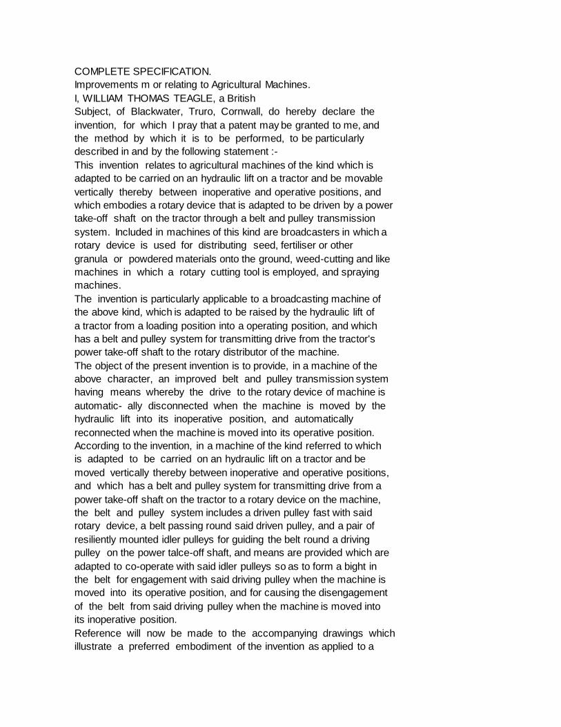
Fig. 1 is a side view of the machine in its operative position ;
Fig. 2 is an enlarged fragmentary plan view taken on the line II-II of
Fig. ;
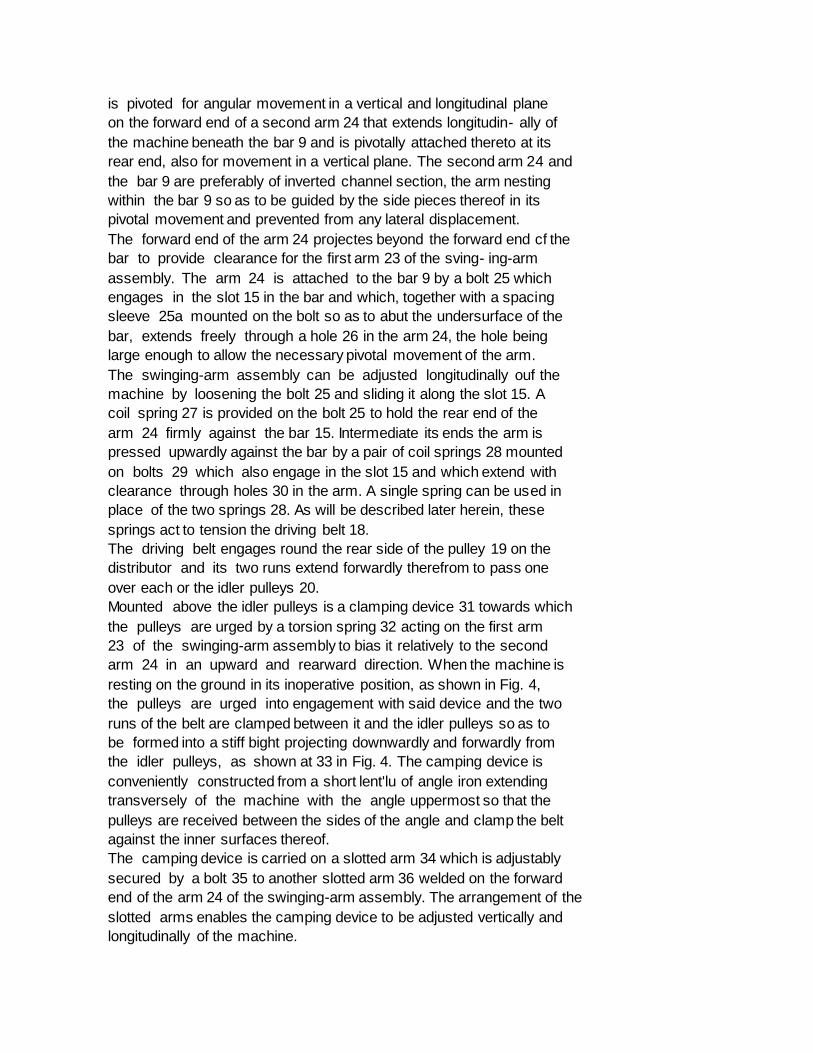
Fig. 3 is an enlarged fragmentary side view of the machine in its
operative position ; and
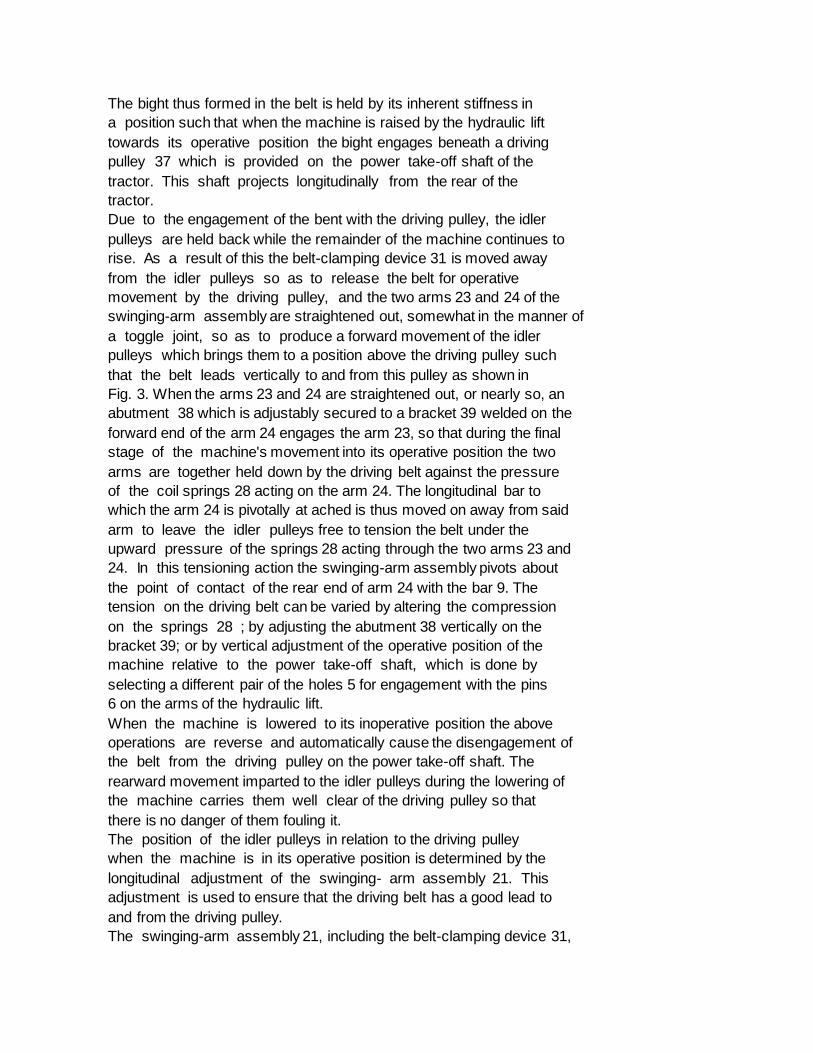
Fig. 4 is a view similar to Fig. 3, showing the machine resting on the
ground in its inoperative or loading position.
In the construction illustrated the machine has a frame on which a
hopper 1 is supported and which comprises two vertical legs 2 arranged
at the front of the hopper and to the sides thereof, and a pair of
arms 3 extending from the legs to the rear of the hopper. The legs are
adapted to be attached to the forked arms 4 of the hydraulic lift on
the rear of a tractor and are arranged to support the machine on the
ground when it is lowered by the hydraulic lift into its inoperative
or loading position, as shown in Fig. 4. For their attachment to the
arms 4 the legs 2 are each formed with a vertical series of holes 5 to
receive the horizontal pins, shown at 6, which are usually provided on
the forked arms of an hydraulic lift. The provision of a series of
holes per- mits vertically adjustment of the operative position of the
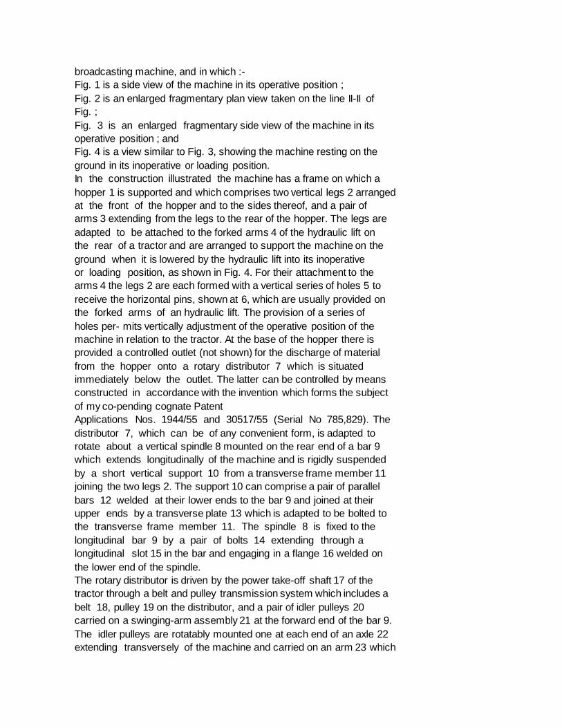
machine in relation to the tractor. At the base of the hopper there is
provided a controlled outlet (not shown) for the discharge of material
from the hopper onto a rotary distributor 7 which is situated
immediately below the outlet. The latter can be controlled by means
constructed in accordance with the invention which forms the subject
of my co-pending cognate Patent
Applications Nos. 1944/55 and 30517/55 (Serial No 785,829). The
distributor 7, which can be of any convenient form, is adapted to
rotate about a vertical spindle 8 mounted on the rear end of a bar 9
which extends longitudinally of the machine and is rigidly suspended
by a short vertical support 10 from a transverse frame member 11
joining the two legs 2. The support 10 can comprise a pair of parallel
bars 12 welded at their lower ends to the bar 9 and joined at their
upper ends by a transverse plate 13 which is adapted to be bolted to
the transverse frame member 11. The spindle 8 is fixed to the
longitudinal bar 9 by a pair of bolts 14 extending through a
longitudinal slot 15 in the bar and engaging in a flange 16 welded on
the lower end of the spindle.
The rotary distributor is driven by the power take-off shaft 17 of the
tractor through a belt and pulley transmission system which includes a
belt 18, pulley 19 on the distributor, and a pair of idler pulleys 20
carried on a swinging-arm assembly 21 at the forward end of the bar 9.
The idler pulleys are rotatably mounted one at each end of an axle 22
extending transversely of the machine and carried on an arm 23 which
is pivoted for angular movement in a vertical and longitudinal plane
on the forward end of a second arm 24 that extends longitudin- ally of
the machine beneath the bar 9 and is pivotally attached thereto at its
rear end, also for movement in a vertical plane. The second arm 24 and
the bar 9 are preferably of inverted channel section, the arm nesting
within the bar 9 so as to be guided by the side pieces thereof in its
pivotal movement and prevented from any lateral displacement.
The forward end of the arm 24 projectes beyond the forward end cf the
bar to provide clearance for the first arm 23 of the sving- ing-arm
assembly. The arm 24 is attached to the bar 9 by a bolt 25 which
engages in the slot 15 in the bar and which, together with a spacing
sleeve 25a mounted on the bolt so as to abut the undersurface of the
bar, extends freely through a hole 26 in the arm 24, the hole being
large enough to allow the necessary pivotal movement of the arm.
The swinging-arm assembly can be adjusted longitudinally ouf the
machine by loosening the bolt 25 and sliding it along the slot 15. A
coil spring 27 is provided on the bolt 25 to hold the rear end of the
arm 24 firmly against the bar 15. Intermediate its ends the arm is
pressed upwardly against the bar by a pair of coil springs 28 mounted
on bolts 29 which also engage in the slot 15 and which extend with
clearance through holes 30 in the arm. A single spring can be used in
place of the two springs 28. As will be described later herein, these
springs act to tension the driving belt 18.
The driving belt engages round the rear side of the pulley 19 on the
distributor and its two runs extend forwardly therefrom to pass one
over each or the idler pulleys 20.
Mounted above the idler pulleys is a clamping device 31 towards which
the pulleys are urged by a torsion spring 32 acting on the first arm
23 of the swinging-arm assembly to bias it relatively to the second
arm 24 in an upward and rearward direction. When the machine is
resting on the ground in its inoperative position, as shown in Fig. 4,
the pulleys are urged into engagement with said device and the two
runs of the belt are clamped between it and the idler pulleys so as to
be formed into a stiff bight projecting downwardly and forwardly from
the idler pulleys, as shown at 33 in Fig. 4. The camping device is
conveniently constructed from a short lent'lu of angle iron extending
transversely of the machine with the angle uppermost so that the
pulleys are received between the sides of the angle and clamp the belt
against the inner surfaces thereof.
The camping device is carried on a slotted arm 34 which is adjustably
secured by a bolt 35 to another slotted arm 36 welded on the forward
end of the arm 24 of the swinging-arm assembly. The arrangement of the
slotted arms enables the camping device to be adjusted vertically and
longitudinally of the machine.
The bight thus formed in the belt is held by its inherent stiffness in
a position such that when the machine is raised by the hydraulic lift
towards its operative position the bight engages beneath a driving
pulley 37 which is provided on the power take-off shaft of the
tractor. This shaft projects longitudinally from the rear of the
tractor.
Due to the engagement of the bent with the driving pulley, the idler
pulleys are held back while the remainder of the machine continues to
rise. As a result of this the belt-clamping device 31 is moved away
from the idler pulleys so as to release the belt for operative
movement by the driving pulley, and the two arms 23 and 24 of the
swinging-arm assembly are straightened out, somewhat in the manner of
a toggle joint, so as to produce a forward movement of the idler
pulleys which brings them to a position above the driving pulley such
that the belt leads vertically to and from this pulley as shown in
Fig. 3. When the arms 23 and 24 are straightened out, or nearly so, an
abutment 38 which is adjustably secured to a bracket 39 welded on the
forward end of the arm 24 engages the arm 23, so that during the final
stage of the machine's movement into its operative position the two
arms are together held down by the driving belt against the pressure
of the coil springs 28 acting on the arm 24. The longitudinal bar to
which the arm 24 is pivotally at ached is thus moved on away from said
arm to leave the idler pulleys free to tension the belt under the
upward pressure of the springs 28 acting through the two arms 23 and
24. In this tensioning action the swinging-arm assembly pivots about
the point of contact of the rear end of arm 24 with the bar 9. The
tension on the driving belt can be varied by altering the compression
on the springs 28 ; by adjusting the abutment 38 vertically on the
bracket 39; or by vertical adjustment of the operative position of the
machine relative to the power take-off shaft, which is done by
selecting a different pair of the holes 5 for engagement with the pins
6 on the arms of the hydraulic lift.
When the machine is lowered to its inoperative position the above
operations are reverse and automatically cause the disengagement of
the belt from the driving pulley on the power take-off shaft. The
rearward movement imparted to the idler pulleys during the lowering of
the machine carries them well clear of the driving pulley so that
there is no danger of them fouling it.
The position of the idler pulleys in relation to the driving pulley
when the machine is in its operative position is determined by the
longitudinal adjustment of the swinging- arm assembly 21. This
adjustment is used to ensure that the driving belt has a good lead to
and from the driving pulley.
The swinging-arm assembly 21, including the belt-clamping device 31,
can be readily applied to a machine for cutting weeds, grass, or like
vegetable ground growth, in which a rotary cutter is supported by a
frame for rotation about a vertical axis, the machine being carried on
the hydraulic lift of a tractor and being movable vertically thereby
between an inoperative position, in which it is clear of the ground,
and a cutting position adjacent the ground. In such application the
swing-arm assembly is inverted from the position shown in the drawings
and is supported on top of a fixed member, which can be the bar 9
similarly inverted. This arrangement operates in a manner similar to
that described above, except that the directions of the various
vertical movements in the different stages of the operation are
reversed. Thus, when the cutting machine is in its inoperative
position, a bight is formed in the belt for engagement with the top of
the driving pulley as the machine is lowered by the hydraulic lift
into its operative cutting position. When the machine is raised back
into its inoperative position the bight is again formed so that the
belt is disengaged from the driving pulley.
What I claim is :-
1. A machine of the kind referred to whicli is adapted to be carried
on an hydraulic lift on a tractor and be moved vertically thereby
between inoperative and operative positions, and which has a belt and
pulley system for transmitting drive from a power take-off on the
tractor to a rotary device on the machine, wherein the belt and pulley
system includes a driven pulley fast with said rotary device, a belt
passing round said driven pulley, and a pair of resiliently mounted
idler pulleys for guiding the belt round a driving pulley on the power
take-off shaft, and wherein means are provided which are adapted to
co-operate with said idler pulleys so as to form a bight in the belt
for engagement with said driving pulley when the machine is moved into
its operative position, and for causing the disengagement of the belt
from said driving pulley when the machine is moved into its
inoperative position.
2. A machine of the kind referred to which is adapted to be carried on
an hydraulic lift on a tractor and to be raised thereby into an
operative position and lowered thereby into an inoperative position,
and which has a rotary distributor and a belt and pulley system for
transmitting drive from a power take-off shaft on the tractor to a
rotary device on the machine, wherein the belt and pulley system
includes a driven pulley fast with said rotary device, a belt passing
round said driven pulley, and a pair of resiliently mounted idler
pulleys for guiding the belt round a driving pulley on the power
take-off shaft, and wherein means are provided which are adapted to
cooperate with said idler pulleys to form a bight in the belt for
engagement with said driving pulley when the machine is raised into
its operative position, and for causing the disengagement of the belt
from said driving pulley when the machine is lowered into its
inoperative position.
* Sitemap
* Accessibility
* Legal notice
* Terms of use
* Last updated: 08.04.2015
* Worldwide Database
* 5.8.23.4; 93p
* GB785831 (A)
Description: GB785831 (A) ? 1957-11-06
Profile grinding machine
Description of GB785831 (A)
PATENT SPECIFICATION
785,831 Date of Application and filing Complete Specification: January
26, 1955.
Application made in Switzerland on February 5, 1954 Complete
Specification Published: November 6, 1957
Index at acceptance:-Class 60, D 1 D( 3 X:4 X), D 2 A( 4:5:8:20).
International Classification:-B 24 b.
COMPLETE SPECIFICATION
Profile Grinding Machine We, DIAMETAL A G, a limited company duly
organised under the law of Switzerland, of Gurzelenstrasse 3, Biel
Switzerland, do hereby declare the invention, for which we pray that a
patent may be granted to us, and the method by which it is to be
performed, to be particularly described in and by the following
statement:-
The present invention relates to improvements in profile grinding
machines comprising a work holder and a tracer which is guidable along
a former plate, as described in the complete specification of our
copending application for letters Patent No 2275/55 (Serial No
785832), and the profile grinding machine as disclosed herein is
characterized by the provision of a control plate which is movable on
the stationary machine frame and to whch are secured 2 Q said former
plate and work holder.
The main objects of the present invention are to provide an
arrangement which permits to grind a prescribed profile very
accurately by relatively simple means, to make the overall height of
the machine small, and to keep the space above the grinding disc free
to permit, for example, of readily mounting an optical control means.
These and related objects are attained by the machine shown, in one
form of invention and by way of example, in the accompanying drawings,
in which:
Fig 1 is a top plan view, Fig 2 is a section through the upper machine
portion on the line II-II of Fig.
1, the parallel guiding means having been omitted, Fig 3 is a front
elevation on a smaller scale, Fig 4 is a side view also on a smaller
scale, Ftg 5 shows a top plan view of a twin pantograph, Fig 6 shows a
section on the line VI-VI lPrice 3 s 6 d l of Fig 5 on a larger scale,
Fig 7 is a top plan view of the work, and Fig 8 is a sideview, partly
in section, of the work 5 G The machine frame consists of a body 1
which at the same time serves as a column, and a cylindrical head 2
which is disposed laterally and slightly offset forwardly of the body
Within said frame, motor 4, suspen 55 ded from a horizontal shaft 3,
is adapted to impart drive to a grooved pulley 6 via a reduction gear
5 At the level of this suspended assembly, the body 1 is closed by a
removable cover la Reduction gear 5 is 60 of the continuously variable
speed type, and the degree of reduction may be adjusted by a handwheel
7 acting through belt 8 and a pulley 9 The rotation of pulley 6
transfers drive through a belt 10 to a fur 65 ther grooved pulley 11
which is journalled upon an arm 12 The pulley 11 is fast upon one end
of a spindle which extends through and is rotatable in the said arm,
and a crank 13 which is coupled to a connecting 7 G rod 14, is secured
upon the opposite spindle end The arm 12 is incorporated and forms a
part of a portion of the machine which is rotatable about stationary
centering pins and 16 and is journalled within and 75 relatively to
the frame about a main vertical axis by bearing members 17 and 18
located in the said main axis The said rotatable machine portion also
includes a U-shaped yoke 19 in one leg 19 a of which 80 the bearing
member 18 for the centreing pin 16 is accommodated The centreing pin
which is engaged by the bearing member 17 is secured in an arm 2 a
integral with head 2 whereas the said bearing member 85 17 is carried
within an ear which is integral with the arm 12.
The web 20 of the U-shaped yoke is formed in its outer face with
vertical Vways with which a vertical slide 21 engages 90 No 2274155 j
785,831 and along which the said slide is adapted to be reciprocated A
downwards extension 22 from the slide is formed with an elongated hole
23 through which a pin 24.
mounted in the connecting rod 14, projects, so that the latter and
thus slide 21 are vertically reciprocated by motor 4 The head of the
slide 21 is formed with horizontal V-ways with which a horizontal
slide 26 makes sliding engagement and is adapted for adjustment
lengthwise of the said ways by a screw 25 a The slide 26 has a head 27
and horizontal V-ways 28 which are located at right angles to the
V-ways in the head 25 are formed in the side of the head adjacent to
the main axis of the machine along which a tool holder 29 is
adjustable by a screw 30, said holder being also movable horizontally,
but at right angles to slide 26 Screws 30 a serve for clamping the
tool holder in its adjusted setting within the V-ways 28 In tool
holder 29 is rotatably mounted a spindle 31 which carries a grinding
disc 32 at the end adjacent the main axis, and a grooved pulley 33 at
the other end Grinding disc 32 may thus be moved in the horizontal
plane into any desired position by slide 26 and tool holder 29, and
vertically by slide 21, connecting rod 14 and eccenritc 13 In the
operating position, the grinding disc is set so that its vertical
tangent which is remote from tool holder 29, i e to the left in Fig 2,
coincides with the machine main axis, and the corresponding tangential
point is the point of contact (working point) with the work.
Thus, the machine portion which is rotatable about the main axis,
essentially comprises the arm 12, yoke 19, the bearing members 17 and
18, the tool holder 29; the means for producing and transferring the
vertical reciprocation to the tool holder, namely the grooved pulley
11, crank 13, connecting rod 14, slides 21 and 26, and grinding disc
32.
A second motor 35 is secured to a platform 34 of body 1, and a grooved
pulley 36 fast upon the motor shaft transfers the rotary movement of
the motor via a belt 37 on to a second grooved pulley 38 The latter
and a further grooved pulley 39 arc fixed to an axle 40 which is
rotatably mounted in a bearing 41 of body 1 A fur.
ther bearing member 42 is rotatable upon shaft 40 and comprises two
symmetrical arms 43 at the ends of which are journalled axles 44 at
right angles thereto, and each axle 44 again carries at its ends two
pulleys 45, 46 and 47, 48, respectively An endless belt 135 is trained
from pulley 39 over pulleys 46, 48, thence through an aperture of a
cover 49, over the driving pulley 33 of grinding disc 32, through said
aperture.
over pulleys 47 and 45 and back to pulley 39 Such arrangement ensures
operation of grinding disc 32 even when the latter, due to its
incorporation in the rotatable machine portion, is swung about the
machine main axis 70 The crown of the frame conssts of a fixed plate
50 of which an arm 50 a carries the centreing pin 16 A control plate
51 is set freely slidable on plate 50, and its relative sliding
movements are limited by its 75 edges 52 and 53 abutting respectively
against corresponding shoulders 54 and 55 of plate 50 On control plate
51 is provided a first V-way 56 (Figure 3) in which a slide 57 is
mounted movable by a screw 58 80 Slide 57 comprises a lug 59 on the
vertical outside face of which is provided a further V-way 60 in which
a slide 62 is mounted movable by a screw 61, said slide 62 being
movable at right angles to slide 57 Slide 85 62 carries a bracket 63
to which is secured a former-plate table 65 by means of a screw 64
Table 65 is provided with two grooves 66 (Fig 1) in which is secured a
former plate 68 by means of screws 67 9 g Opposite former-plate
profile 68 a is disposed a tracer 69 which is retained in d V-way 70
in vertically movable relation, the corresponding clamping screw being
designated by 71 The V-way 70 is pro g 5 vided with an extension 72
which points towards former plate 68 and is fixed to a lever 73 to
which, at 74 and 75, are pivoted two arms 76, 77 of a parallel guiding
means The latter further comprises, in con 100 ventional manner, rings
78 and 79 and further arms 80 to 83 The connection and disposition of
said rings and arms corresponds to the conventional arrangement of a
parallel guiding means The last arms 82 105 and 83 of the latter are
pivoted, at 84 and 85, to a plate 86 which is incorporated in and
forms the upper leg of the U-shaped yoke 19 Any and each rotary
movement of tracer 69 thus is transmitted, via the 110 lever 73 and
the parallel guiding means 76 to 83, on to the yoke 19 and, therefore,
on to the grinding disc 32 as a consequence of the rotatable portion
of the machine turning about the main axis Translatory move 115 ments
of the tracer, i e movements which do not provoke any angular movement
of ring 78, do not bias the movable machine portion, as far as the
transmission on to the parallel guiding means is concerned 120 The
arms 80 and 81 of the latter are interconnected by a strap 87 of which
the ends are pivoted to said arms at 88 and 89.
To strap 87 is rotatably secured a vertical pin 90 to the free end of
which are 125 pivoted two rollers 91 which run in a groove 92 of a
rail 93 The latter is connected to control plate 51 via a pedestal 94
and screws 95 The parallel guiding means thus is supported through
said 130 785,831 rollers on the control plate 51, without impairing
the mobility thereof.
To V-way 70 of tracer 69 is pivoted the long arm 96 of a first
individual panto.
graph which comprises, in a conventional manner, said long arm 96 and
other arms 97 to 99 which are interconnected in pivotable relation Leg
99 at 100 is rotatably mounted in a bearing 101 of control plate -0
51, whilst leg 98 is pivoted to the long arm 102 of a second

individual pantograph.
Bearing 101 is secured to control plate 51 by screws 101 a, elongated
holes 101 b being provided in the control plate so that the J 5
bearing and, thus, the point of articulation of pantograph 96 to 99 is
movable on the control plate relatively thereto and may oe
screw-locked thereto again Said second pantograph is fundamentally
constructed :20 similar to the first and comprises, besides leg 102,
two parallel legs 103, 104 and a leg 105 which is parallel to long leg
10 ?.
The two hingeably interconnected pantographs 96 to 99 and 102 to 105
together :25 form a twin pantograph Each of the legs 104, 105 (Fig 5)
has a slot 104 a and 105 a respectively, and in each of these slots is
movably mounted a sliding block 106 and 107 respectively The latter
may be fixed in their positions by screws 108 and 109 ac.
cording to the desired reduction ratio Each of the blocks 106, 107
comprises an underplate 110 which is secured in its position by screws
111, the edge of said plate securing the pivot pin 112 and 113
respectively The two pins 112, 113 stand at right angles to the plane
of the pantograph, pin 112 which is fixed to leg 105, pointing
upwardly and pin 113 which is fixed to leg -40 104, pointing
downwardly Pin 113 is rotatably held in an eye 114 of an arm 115 which
is secured to control plate 51 by means of screws 116 Pin 112 forms
the fixed point of the pantograph, is situated in the machine main
axis and is journalled in leg 19 b of the yoke 19 which as already
explained, belongs to the rotatable machine portion.
From the foregoing may be seen that -50 each single pantograph at one
point ( 100 and 113 respectively) is rotatably connectedto the control
plate 51, whilst the twin pantograph has a fixed point ( 112) situated
in the machine main axis.
Control plate 51 further comprises a bracket 118 (Fig 3) to the upper
side of which is attached a plate 119 On the latter is secured by
screws 120 a carriage 121 with respect to which the work slide 122 is
movable, at right angles to slide 57, so far laterally as is permitted
by a slot 123 of the work slide, said slot being traversed by a screw
124 for attachment to the carriage A guide pin 123 a serves for
rectilinearly guiding such displacing movement In work slide 122 is
mounted a work spindle 125 which is rotatable by meansj of a handwheel
126 The work 128 is clamped to spindle 125 by means of a screw 127 For
the sake of clarity, the 70 work slide in Fig 3 has been moved to the
right so that the work becomes visible next to grinding disc 32,
whereas in reality the latter and the work are situated in the same
vertical plane The work spindle 125 75 carries an indexing wheel 129
which coacts with two pawls 130 of which only the upper one is visible
in the drawing These pawls are pivoted at 131 (Fig 1) and are
disengageable from index wheel 129 by 80 means of a lever 132.
On the control plate 51 is provided a guide means 133 on which may be
mounted an optical control device 134 of known construction and which
is schematically 85 shown in Figs 3 and 4.
To perform a grinding operation in the machine after the work 128 has
been mounted upon the spindle 125 in the plane of the rotating and
vertically reciprocating 9 o grinding disc 32, and the former plate 68
has been clamped upon the control plate 51, the tracer is moved
linearly towards the former plate so as to take the work into contact
with the disc 95 The work is taken into contact with the disc because
the said movement of the tracer imparts a corresponding movement to
that end of the longer arm 96 of the first individual pantograph on
which the tracer 100 O is pivoted, thereby tending to impart a similar
movement to the said arm; since the arm is pivoted to the pantograph
arms 97, 99 which are also pivoted upon the control plate at 100 the
said longer arm 105 and the arm 98 are constrained to make combined
linear and swinging movements.
The combined movement of the arm 98 displaces the longer arm 102 of
the second individual pantograph in a manner which 110 tends to swing
the arm 104 of the second pantograph about the pivot pin 113 and
impart a combined longitudinal and swinging movement to the arm 105;
however since the arm 105 is pivoted about the pin 115 112 which is
held in the main axis of the machine, the said arm is prevented from
making any longitudinal movement with the result that the pivot pin
113 is moved and, since the pin is mounted on the con 120 trol plate,
the said plate is moved carrying with it the pivot 100 The arrangement
of the two individual pantographs is such that the movement imparted
therethrough from the tracer to the control plate causes the 125 plate
(and therefore the work) to move in the opposite direction to, but
through a smaller distance than, the tracer, the relative distances of
travel being determined by the location of the blocks 106 and 107 130
a' lengthwise of their respective slots 104 a and 105 a.
Having taken the work into contact with the periphery of the grinding
disc, the tracer is moved laterally relative to the former plate
whereupon the control plate and work are again displaced by the
pantographs in the opposite direction to, but through a smaller
distance than, the tracer so that the work is traversed across and in
contact with the disc periphery and is ground away until the tracer
comes into abutment with the profile 68 a of the former plate.
In the event that, in making each traversing movement across the
profile, the tracer is swung about its pivoted connection to the
longer arm 96 of the first individual pantograph, the lever 73, which
is fixed to the tracer, is swung in the same direction and through the
same angle so as to actuate the parallel guiding means 74 and 83
whereby the grinding disc is swung through an identical angle about
the main axis of the machine.
Since linear movements of the tracer into contact with and across the
profile 68 a are translated, on a reduced scale, to the work via the
twin panto-graphs and the control 3 Q plate, and angular movements of
the said tracer are translated to the grinding disc via the parallel
grinding means, the profile imparted to the work is identical but on a
reduced scale relatively to the profile of the former plate.
The progress of the grinding operation may be followed visually by the
operator of the machine since an enlarged image of the profile
imparted to the work is projected on to a screen of the optical device
134; consequently the carrying out of the grinding operation is
facilitated.
* Sitemap
* Accessibility
* Legal notice
* Terms of use
* Last updated: 08.04.2015
* Worldwide Database
* 5.8.23.4; 93p
* GB785832 (A)
Description: GB785832 (A) ? 1957-11-06
Profile grinding machine
Description of GB785832 (A)
PATENT SPECIFICATION
Date of Application and filing Complete Specification: January 26,
1955.
Application made in Switzerland on February 5, 1954 Complete
Specification Published: November 6, 1957
Index at acceptance:-Class 60, D 1 D( 3 D:4 X), D 2 A( 4:5:8:20).
International Classification:-B 24 b.
COMPLETE SPECIFICATION
Profile Grnding Machine We, DIAMETAL A G, a limited company duly
organised under the Law of Switzerland, of Gurzelenstrasse 3, Biel,
Switzerland, do hereby declare the invention, for which we pray that a
patent may be granted to us, and the method by which it is to be
performed, to be particularly described in and by the following
statement:-
The present invention relates to improvements in profile grinding
machines comprising a work holder and a tracer which is guidable along
a former plate, and the profile grinding machine as disclosed herein
is characterized by the provision of a control plate which is movable
on the stationary machine frame and to which are secured said former
plate and work holder, as described in our co-pending application for
letters patent No 2274/55 (Serial No.
785,831).
The main objects of the present invention are to provide an
arrangement which permits to grind a prescribed profile very
accurately by relatively simple means, to make the overall height of
the machine small, and to keep the space above the grinding disc free
to permit, for example, of readily mounting an optical control means.
Those and related objects are attained by the machine shown, in one
form of invention and by way of example, in the accompanying drawings,
in which:
Fig 1 is a top plan view, Fig 2 is a section through the upper machine
portion on the line II-II of Fig 1.
the parallel guiding means having been omitted, Fig 3 is a front
elevation on a smaller scale, Fig 4 is a side view also on a smaller
scale, Fig 5 shows a top plan view of a twin pantograph, Fig 6 shows a
section on the line VI-VI of Fig 5 on a larger scale, Fig 7 is a top
plan view of the work, and lPrice 3 s 6 d I Fig 8 is a side view,
partly in section, of the work.
The machine frame consists of a body 1 which at the-same time serves
as a column, and a cylindrical head 2 which is disposed 5 (X}
laterally and slightly offset forwardly of the body Within said frame,
a motor 4, suspended from a horizontal shaft 3, is adapted to impart
drive to a grooved pulley 6, via a reduction gear 5, at the level of
this sus 55 pended assembly the body 1 is closed by a removable cover
la Reduction gear 5 is of the continuously variable speed type, and
the degree of reduction may be adjusted by a handwheel 7 acting
through a belt 8 and 60 a pulley 9 The rotation of pulley 6 transfers
drive through a belt 10 to a further grooved pulley 11 which is
journalled upon an arm 12 The pulley 11 is fast upon one end of a
spindle which extends through and 65 is rotatable in the said arm, and
a crank 13 which is coupled to a connecting rod 14, is secured upon
the opposite spindle end The arm 12 is incorporated in and forms a
part of a portion of the machine which is rotat 70 able about
stationary centreing pins 15 and 16 and is journalled within and
relatively to the frame about a main vertical axis by bearing members
17 and 18 located in the said main axis The said rotatable machine 75
portion also includes a U-shaped yoke 19 in one leg 19 a of which the
bearing member 18 for the centreing pin 16 is accommodated.
The centreing pin which is engaged by the bearing member 17, is
secured in an arm 2 a 89 integral with head 2 Whereas the said bearing
member 17 is carried within an ear which is integral with the arm 12.
The web 20 of the U-shaped yoke is formed in its outer face with
vertical V-ways 85 with which a vertical slide 21 engages and along
which the said slide is adapted to be reciprocated A downwards
extension 22 from the slide is formed with an elongated hole 23
through which a pin 24, mounted 90 785,832 No 2275/55 785,832 in the
connecting rod 14, projects so that the latter and thus slide 21 are
vertically reciprocated by motor 4 The head 25 of slide 21 is formed
with horizontal V-ways with which a horizontal slide 26 makes sliding
engagement and is adapted for adjustment lengthwise of the said ways
by a screw a The slide 26 has a head 27 and horizontal V-ways 28 which
are located at right angles to the V-ways in the head 25 are formed in
the side of the head adjacent to the main axis of the machine, along
which a tool holder 29 is adjustable by a screw 30, said holder being
also movable horizontally, J 5 but at right angles to slide 26 Screws
30 a serve for clamping the tool holder in its adjusted setting within
the V-ways 28 In tool holder 29 is rotatably mounted a spindle 31
which carries a grinding disc 32 at the end adjacent the main axis,
and a grooved roller 33 at the other end Grinding disc 32 thus may be
moved in the horizontal plane into any desired position by slide 26
and tool holder 29, and verticaly by slide 21, connecting rod 14 and
eccentric 13 In the operating position, the grinding disc is set so
that its vertical tangent which is remote from tool holder 29, i e to
the left in Fig.
2, coincides with the machine main axis, and the corresponding
tangential point is the point of contact (working point) with the
work.
Thus, the movable machine portion which is rotatable about the main
axis, essentially comprises the arm 12, yoke 19, the bearing members
17 and 18, the tool holder 29, the means for producing and
transferring the vertical reciprocation to the tool holder, namely the
grooved pulley 11, crank 13, connecting rod 14, slides 21 and 26, and
grinding disc 32.
A second motor 35 is secured to a platform 34 of body 1, and a grooved
pulley 36 fast upon the motor shaft transfers the rotary movement of
the motor via a belt 37 to a second grooved pulley 38 The latter and a
further grooved pulley 39 are fixed to an axle 40 which is rotatably
mounted in a bearing 41 of body 1 A further bearing member 42 is
rotatably held in the axis of shaft 40 and comprises two symmetrical
arms 43 at the ends of which are journalled axles 44 at right angles
thereto, and each axle 44 again carries at its ends two pulleys 45, 46
and 47, 48 respectively An endless belt 135 is trained from pulley 39
over pulleys 46 and 48, thence through an aperture of a cover 49, over
the driving pulley 33 of grinding disc 32, through said aperture, over
pulleys 47 and 45 and back to pulley 39 Such arrangement ensures
operation of grinding disc 32 even when the latter, due to its
incorporation in the rotatable machine portion, is swung about the
machine main axis.
The crown of the frame consists of a fixed plate 50 of which an arm 50
a carries the centreing pin 16 A control plate 51 is set freely
slidable on plate 50, and its relative sliding movements are limited
by its edges 52 70 and 53 abutting respectively against corresponding
shoulders 54 and 55 of plate 50 In control plate 51 is provided a
first V-way 56 (Figure 3) in which a slide 57 is mounted and is
adjustable by a screw 58 Slide 57 75 comprises a lug 59 on the
vertical outside face of which is provided a further V-w vay in which
a slide 62 is mounted and is adjustable by a screw 61, said slide 62
being movable at right angles to slide 57 Slide 62 80 carries a
bracket 63 to which is secured a former-plate table 65 by means of a
screw 64 Table 65 is provided with two grooves 66 (Fig 1) in which is
secured a former plate 68 by means of screws 67 Opposite former 85
plate profile 68 a is disposed a tracer 69 which is retained in a
V-way 70 in vertically movable relation, the corresponding clamping
screw being designated by 71 The V-way 70 is provided with an
extension 72 which 90 points towards former plate 68 and is fixed to a
lever 73 to which, at 74 and 75, are pivoted two arms 76, 77 of a
parallel guiding means The latter further comprises, in a conventional
manner, rings 78 and 79 and 95 further arms 80 to 83 The connection
and disposition of said rings and arms corresponds to the conventional
arrangement of a parallel guiding means The last arms 82 and 83 of the
latter are pivoted, at 84 and 100 85, to a plate 86 which is
incorporated in and forms the upper leg of the V-shaped yoke 19 Any
and each rotary movement of tracer 69 thus is transmitted, via the
lever 73 and the parallel guiding means 76 105 to 83, on to the yoke
19 and, therefore, on to the grinding disc 32 as a consequence of the
rotatable portion of the machine turning about the main axis
Translatory movements of the tracer, i e movements which do 110 not
provoke any angular movement of ring 78, do not bias the movable
machine portion, as far as the transmission on to the parallel guiding
means is concerned The arms 80 and 81 of the latter are inter 1 15
connected by a strap 87 of which the ends are pivoted to said arms at
88 and 89.
To strap 87 is rotatably secured a vertical pin 90 to the free end of
which are pivoted two rollers 91 which run in a groove 120 92 of a
rail 93 The latter is connected to control plate 51 via a pedestal 94
and screws The parallel guiding means thus is supported through said
rollers on the control plate 51, without impairing the mobility 125
thereof.
To V-way 70 of tracer 69 is pivoted the long arm 96 of a first
individual pantograph which comprises, in conventional manner, said
long arm 96 and other arms 97 to 99 130 785,832 which are
interconnected in pivotable relation Leg 99 at 100 is rotatably
mounted in a bearing 101 of control plate 51, whilst leg 98 is pivoted
to the long arm 102 of a second individual pantograph Bearing 101 is
secured to control plate 51 by screws 101 a, elongated holes 101 b
being provided in the control plate so that the bearing and, thus, the
point of articulation of pantograph 96 to 99 is movable on the control
plate relatively thereto and may be screw-locked thereto again Said
second pantograph is fundamentally constructed similar to the first
and comprises, besides leg 102, two parallel legs 103, 104 and a leg
105 whch is parallel to long leg 102 The two hingeably interconnected
pantographs 96 to 99 and 102 to 105 together form a twn pantograph
Each of the legs 104, 105 (Fig 5) has a slot 104 a :0 and 105 a
respectively, and in each of these dlots is movably mounted a sliding
block 106 and 107 respectively The latter may be fixed in their
positions by screws 108 and 109 according to the desired reduction
ratio.
-25 Each of the blocks 106, 107 comprises an underplate 110 which is
secured in its position by screws 111, the edge of said plate securing
the pivot pin 112 and 113 respectively The two pins 112, 113 stand at
right :30 angles to the plane of the pantograph, pin 112 which is
fixed to leg 105, pointing upwardly and pin 113 which is fixed to leg
104, pointing downwardly Pin 113 is rotatably held in an eye 114 of an
arm 115 which -35 is secured to control plate 51 by means of screws
116 Pin 112 forms the fixed point of the pantograph, is situated in
the machine main axis and is journalled in leg 19 b of yoke 19 which,
as already explained, belongs to the rotatable machine portion.
From the foregoing may be seen that each single pantograph at one
point ( 100 and 113 respectively) is rotatably connected to the
control plate 51, whilst the twin pantograph has a fixed point ( 112)
situated in the machine main axis.
Control plate 51 further comprises a bracket 118 (Fig 3) to the upper
side of which is attached a plate 119 On the latter -50 is secured by
screws 120 a carriage 121 with respect to which the work slide 122 is
movable, at right angles to slide 57, so far laterally as is permitted
by a slot 123 of the work slide, said slot being traversed by a -55
screw 124 for attachment to the carriage.
A guide pin 123 a serves for rectilinearly guiding such displacing
movement In work slide 122 is mounted a work spindle 125 which is
rotatable by means of a handwheel 126 The work 128 is clamped to
spindle by means of a screw 127 For the sake of clarity, the work
slide in Fig 3 has been moved to the right so that the work becomes
visible next to grinding disc 32, whereas in -G 5 reality the latter
and the work are situated in the same vertical plane The work spindle
carries an indexing wheel 129 which coacts with two pawls 130 of which
only the upper one is visible in the drawing These pawls are pivoted
at 131 (Fig 1) and are 70 disengageable from index wheel 129 by means
of a lever 132.
On the control plate 51 is provided a guide means 133 on which may be
mounted an optical control device 134 of known con 75 struction and
which is schematically shown in Figs 3 and 4.
To perform a grinding operation in the machine after the work 128 has
been mounted upon the spindle 125 in the plane 80 of the rotating and
vertically reciprocating grinding disc 32, and the former plate 68 has
been clamped upon the control plate 51, the tracer is moved linearly
towards the former plate so as to take the work into 85 contact with
the disc.
The work is taken into contact with the disc because the said movement
of the tracer imparts a corresponding movement to that end of the
longer arm 96 of the first indi 90 vidual pantograph on which the
tracer is pivoted, thereby tending to impart a similar movement to the
said arm; since the arm is pivoted to the pantograph arms 97, 99 which
are also pivoted upon the control plate at 95 the said longer arm and
the arm 98 are constrained to make combined linear and swinging
movements The combined movement of the arm 98 displaces the longer arm
102 of the second individual pantograph 100 in a manner which tends to
swing the arm 104 of the second pantograph about the pivot pin 113 and
impart a combined longitudinal and swinging movement to the arm 105;
however since the arm 105 is pivoted 105 about the pin 112 which is
held in the main axis of the machine, the said arm is prevented from
making any longitudinal movement with the result that the pivot pin
113 is moved and, since the pin is mounted on 110 the control plate,
the said plate is moved carrying with it the pivot 100 The arrangement
of the two individual pantographs is such that the movement imparted
therethrough from the tracer to the control plate 115 causes the plate
(and therefore the work) to move in the opposite direction to, but
through a smaller distance than, the tracer, the relative distances of
travel being determined by the location of the blocks 106 and 120 107
lengthwise of their respective slots 104 a and 105 a.
Having taken the work into contact with the periphery of the grinding
disc, the tracer is moved laterally relative to the former 125 plate
whereupon the control plate and work are again displaced by the
pantographs in the opposite direction to, but through a smaller
distance than, the tracer so that the work is traversed across and in
contact with 13 Or 785,832 the disc periphery and is ground away until
the tracer comes into abutment with the profile 68 a of the former
plate.
In the event that, in making each traversing movement across the
profile, the tracer is swung about its pivoted connection to the
longer arm 96 of the first individual pantograph, the lever 73, which
is fixed to the tracer, is swung in the same direction and through the
same angle so as to actuate the parallel guiding means 74 and 83
whereby the grinding disc is swung through an identical angle about
the main axis of the machine.
J 5 Since linear movements of the tracer into contact with and across
the profile 68 a are translated, on a reduced scale, to the work via
the twin pantographs and the control plate, and angular movements of
the said tracer are translated to the grinding disc via the parallel
grinding means, the profile imparted to the work is identical but on a
reduced scale relatively to the profile of the former plate.
The progress of the grinding operation may be followed visually by the
operator of the machine since an enlarged image of the profile
imparted to the work is projected on to a screen of the optical device
134: consequently the carrying out of the grinding operation is
facilitated.
* Sitemap
* Accessibility
* Legal notice
* Terms of use
* Last updated: 08.04.2015
* Worldwide Database
* 5.8.23.4; 93p
* GB785833 (A)
Description: GB785833 (A) ? 1957-11-06
Improvements in or relating to a method and apparatus for effecting
transmissions oftelevision images
Description of GB785833 (A)
A high quality text as facsimile in your desired language may be available
amongst the following family members:
BE526230 (A) FR1019549 (A) US2786887 (A) FR64960 (E)
BE526230 (A) FR1019549 (A) US2786887 (A) FR64960 (E) less
Translate this text into Tooltip
[85][(1)__Select language]
Translate this text into
The EPO does not accept any responsibility for the accuracy of data
and information originating from other authorities than the EPO; in
particular, the EPO does not guarantee that they are complete,
up-to-date or fit for specific purposes.
PATENT SPECIFICATION
785,833 Date of Application and filing Complete Specification:
February 2, 1954.
Application made in France on Februarny 4 1953 Complete Specification
Published: Novemlber 6, 1957
No 3094/54 J Index at acceptance:-Class 40 ( 3), F( 2 F 3:2 X:3 A:6
K).
International Classification:-HO 4 n.
COMPLETE SPECIFICATION
Improvements in or relating to a Method and Apparatus for Eiecting
Transmissions of Television Images We, SOCIETE NOUVELLE DE L'OUTILLAGE
R.B V ET DE LA RADIO-INDUSTRIE, 45 Avenue K 16 ber, Paris 16 eme,
France, a Body Corporate organised according to the laws of France, do
hereby declare the invention, for which we pray that a patent may be
granted to us, and the method by which it is to be performed, to be
particularly described in and by the following statement:-
This invention is ain improvement in or modification of the invention
forming the subject matter of British Patent No 694,005 which
describes an apparatus for producing a transmission of television
pictures wherein from a video-signal of normal television standard
frequency a recording is produced occupying a narrower bandwidth the
said recording being transmitted and reconverted at the receiving
station to a video-signal of the original bandwidth whereby the
reduced frequency band is required for the transmission.
According to the said prior Patent No.
694,005 one method of producing the recording was to use a light
sensitive film which was then developed and scanned thus making it
possible to scan any one or more of the pictures so produced at the
desired bandwidth for transmission purposes At the receiving end the
procedure was reversed by again producing a permanent recording on a
light sensitive film which was developed and the frames thereon
scanned the requisite number of times to reconvert the narrow
bandwidth transmission to the standard frequency video-signal In the
second method described in the above Patent No 694,005 instead of
using a light sensitive film an electro-static process was employed
whereby the video-signal was used to impose on the target of a storage
tube electrostatic charges corresponding to the image of the
video-signal Such targets were then scanned at any desired lower speed
to produce a narrow bandwidth signal for transmissions.
lPrice 3 s 6 d l At the receiving end the low frequency signal was
again imposed on a number of targets in a bank of storage tubes the
number of targets being such that they could be scanned in succession
at the scanning fre 50 G quency of the original signal.
The method used in said prior Patent to effect a lower scanning
frequency recording for transmission over a reduced frequency band,
was to omit some of the frames, by 55 scanning at a lower frequency
The picture was then restored at the receiving end by scanning some of
the frames more than once at the original frequency.
In the present invention instead of omit 60 ting some of the frames,
all the frames are in fact transmitted over the narrow bandwidth
channel, but some of the lines in each frame are omitted, by scanning
at a lower frequency, the original picture line number 65 being
restored at the receiving end by scanning some of the lines more than
once to replace the omitted lines.
In the B B C high definition television service the picture is
composed of 405 horizon 70 Q tal lines and there are 25 complete
pictures per second A system of interlaced scanning is used in which
the odd numbered lines of the picture are scanned in 1/50th second and
the even numbered lines are scanned in 75 the succeeding 1/50th second
When this picture is transmitted over the narrow bandwidth cable, each
frame still lasts 1/50th second, but the number of lines contained in
each frame is reduced to a half or a third or 80 > some other
convenient sub multiple.
The frequency band occupied by a television signal is equal to the
frame scanning frequency times the line per picture number times the
dot per line number The horizon 85, tal definition rests on the number
of dots and the vertical definition on the number of lines and the
type of scanning (interlaced or plain) Numerous tests have confirmed
that when the number of lines of a television pic 9 g / 785,833 ture

are reduced, there results an impression of loss of vertical
definition even if interlaced scanning is maintained However if the
high number of lines is preserved, but with S one or even two
repetitions of the same lines, for some of them, or each of them, the
subjective vertical definition and accurateness in details of the
picture persists, provided the horizontal definition remains constant.
Actually, during the transmission through the narrow bandwidth
channel, the line frequency of the video-signal is lowered so that.
during a frame period, only part of the lines constituting the picture
are conveyed along said transmission channel with the same frequency
band as delivered by the pick-up equipment, that is to say that each
second (or third or so on), line is transmitted with full details
while the other lines are suppressed.
During one normal frame period, only some of the lines are therefore
transmitted along the channel, the remaining lines are transmitted
during the succeeding picture since the succeeding frame does not
include the same lines owing to the fact that interlaced scanning is
used At the end of the transmission channel, the signal is displayed
at the reduced scanning rate on a long after glow picture tube which
co-operates with a pick-up tube, the scanning frequencies being chosen
according to the required values to match the receiving sets at the
point of location of the end of the transmission channel.
These will not necessarily be the same as those used at the pick-up
end of the television chain.
According to the present invention we provide a method of generating a
television signal representing television pictures formed by a given
number of lines scanned at a first frequency which consists in
deriving a signal by scanning the said television picture at a second
frequency lower than said first frequency in such a way that all the
frames are scanned and some of the lines omitted, transmitting said
signal through a narrow bandwidth transmission channel, receiving said
signal and producing therefrom a television picture signal of the
original number of lines at a frequency equal to the first frequency
by repeating the signal of adjacent lines to replace the missing
lines; and we also provide an apparatus for carrying out the above
method comprising at the transmitting end a picture tube displaying
the television picture to be transmitted and optical means to project
said picture onto a pick-up tube the scanning assembly of which is
operated at said second frequency for producing the signal to be
transmitted, and at the receiving end a picture tube on which a
television picture is displayed by scanning at said second frequency,
optical means for projecting said picture on a pick-up tube and means
for scanning said picture at the first frequency some of the lines
being scanned more than once to build up the said picture signal
containing said first given number of 70 lines.
The invention will be well understood by referring to the following
description of the embodiment of the invention using intermediate
equipments including a pick-up and a 75 picture tube, in combination,
at both ends of the transmission channel It is well understood that
other equivalent means may be used to modify the line scanning
frequency such as for instance special cathode ray tubes 80 including
a storage target and one or two electron gun assemblies such, for
instance, as the tubes shown on Figures 3 and 4 of the parent Patent.
Figure 1 and Figure 2 of the accompany 85 ing drawings show such
intermediate equipment at both ends of the transmission channel shown
as coaxial cable 4 Cathode ray tube 1 of Figure 1 gives a picture of
the incoming video-signal using interlaced scan 90 ning rates in
accordance with the standard scanning rates used at the pick-up
equipment (that is 50 frames of 2021 lines per second) The picture
displayed is focussed by means of an optical system shown as 2 95 on
the photosensitive surface of pick-up tube 3 which feeds the input of
the narrow bandwidth transmission channel such as a cable 4, by means
of video amplifiers not shown on the Figure The scanning of target of
tube 100 3 is made at a slower rate than the corresponding scanning
speed on picture tube 1.
The decrease in speed is chosen so that the narrow bandwidth of cable
4 will be able to transmit the whole of the information in 105 cluded
in each point of the picture displayed by tube 1 at a repetition
frequency less than per second.
Figure 3 shows the line scanning voltages as applied to picture tube 1
and pick-up tube 110 3 Curve A shows the line scanning voltage applied
to tube 1 and curve B the line scanning voltage of camera tube 3 In
this case the speed of the line scanning on camera tube 3 is half the
speed on picture tube 1 Under 115 these conditions, vertical
deflecting voltages are applied at half the frame frequency to the
camera tube Interlaced scanning is maintained on camera tube 3 Picture
tube 1 is of the ordinary type used in television sets The 120 output
signal from tube 3 occupies a frequency band which has half the width
necessary to the signal applied to tube 1, to obtain the same
horizontal definition.
Curve C of Figure 3 shows the line scan 125 ning signal in the case
when the reduction of the line scanning speeds are 2 to 5 between
picture tube 1 and camera tube 3 In this case only two lines out of
every five are transmitted along cable 4 130 785,833 At the terminal
of cable 4 as shown on Figure 2, the video signal is applied, by means
of a video amplifier 5, to the modulating electrode of picture tube 6
The scanning voltages applied to picture tube 6 are identical with the
scanning voltages used in camera tube 3 which in this example is half
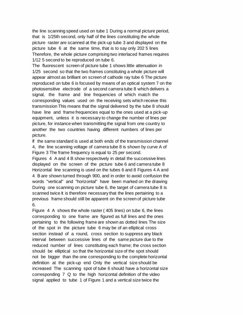
the line scanning speed used on tube 1 During a normal picture period,
that is 1/25th second, only half of the lines constituting the whole
picture raster are scanned at the pick-up tube 3 and displayed on the
picture tube 6 at the same time, that is to say only 202 5 lines
Therefore, the whole picture comprising two interlaced frames requires
1/12 5 second to be reproduced on tube 6.
The fluorescent screen of picture tube 1 shows little attenuation in
1/25 second so that the two frames constituting a whole picture will
appear almost as brilliant on screen of cathode ray tube 6 The picture
reproduced on tube 6 is focused by means of an optical system 7 on the
photosensitive electrode of a second camera tube 8 which delivers a
signal, the frame and line frequencies of which match the
corresponding values used on the receiving sets which receive this
transmission This means that the signal delivered by the tube 8 should
have line and frame frequencies equal to the ones used at a pick-up
equipment, unless it is necessary to change the number of lines per
picture, for instance when transmitting the signal from one country to
another the two countries having different numbers of lines per
picture.
If the same standard is used at both ends of the transmission channel
4, the line scanning voltage of camera tube 8 is shown by curve A of
Figure 3 The frame frequency is equal to 25 per second.
Figures 4 A and 4 B show respectively in detail the successive lines
displayed on the screen of the picture tube 6 and camera tube 8
Horizontal line scanning is used on the tubes 6 and 8 Figures 4 A and
4 B are shown turned through 900, and in order to avoid confusion the
words "vertical" and "horizontal" have been marked on the drawing
During one scanning on picture tube 6, the target of camera tube 8 is
scanned twice It is therefore necessary that the lines pertaining to a
previous frame should still be apparent on the screen of picture tube
6.
Figure 4 A shows the whole raster ( 405 lines) on tube 6, the lines
corresponding to one frame are figured as full lines and the ones
pertaining to the following frame are shown as dotted lines The size
of the spot in the picture tube 6 may be of an elliptical cross
section instead of a round, cross section to suppress any black
interval between successive lines of the same picture due to the
reduced number of lines constituting each frame; the cross section
should be elliptical so that the horizontal size of the spot should
not be bigger than the one corresponding to the complete horizontal
definition at the pick-up end Only the vertical size should be
increased The scanning spot of tube 6 should have a horizontal size
corresponding 7 Q to the high horizontal definition of the video
signal applied to tube 1 of Figure 1 and a vertical size twice the

size corresponding to the whole number of lines of the raster ( 405
for the area of the picture), that is a vertical 75 size larger than
d' and smaller than 2 d' (distance between two successive lines of the
same frame of scansion on the target of tube 8) Thereby, information
is picked-up during each line scanning of target of tube 8 The 8 j
raster on tube 8 is shown in Fig 4 B. If desired, the display of the
picture on intermediate picture tubes 1 and 6 may be made as a
negative picture of the scene being televised, as described in our
British Patent 85 No 776,764 Also allowance may be made for an
automatic gamma and shading correction when the pick-up equipment
comprises a supericonoscope type of tube.
As was said above, it is necessary that the 90 brilliancy of the
different parts of the picture displayed on picture tube 6 at
successive frame intervals be equal, so as to provide for the high
quality output signal from camera tube 8 95 Such a condition may be
obtained by controlling the gain of the video amplifier 5 or of the
picture tube 6 as is described in our British Application No 4249/54
(Serial No.
784,856 10
* Sitemap
* Accessibility
* Legal notice
* Terms of use
* Last updated: 08.04.2015
* Worldwide Database
* 5.8.23.4; 93p