5.3: Novel Design for Color Electrochromic Display · 5.3: Novel Design for Color Electrochromic...
4
5.3: Novel Design for Color Electrochromic Display Tohru Yashiro, Shigenobu Hirano, Yoshihisa Naijoh, Yoshinori Okada, Kazuaki Tsuji, Mikiko Abe, Akishige Murakami, Hiroyuki Takahashi, Koh Fujimura, Hitoshi Kondoh Ricoh Company, Ltd., Research and Development Group 16-1 Shinei-cho, Tsuzuki-ku Yokohama, Kanagawa, Japan Abstract We have developed a technology for a new full-color reflective electrochromic display (ECD) based on the subtractive color mixing model. This improves display brightness and color reproducibility. Additional advantage is simple production process. An active matrix driving of the full-color reflective ECD has been demonstrated successfully. 1. Introduction Electronic papers are increasing in commercial mainly using black and white reflective display. But bright full-color reflective displays are now still under development. Without its own light source it is difficult to achieve bright color. This is because light use efficiency is too low when using Red/Green/Blue color filter such as conventional liquid crystal displays (LCD). Therefore, several full-color display technologies without using color filter have been developed. The first is cholesteric liquid crystals (ChLCs) technology [1]. This device is based on stacked three kinds of ChLCs display units* (*display unit = display layer sandwiched by a pair of substrate with transparent electrode). The three kinds of ChLCs show each red, green, blue color by selective reflections. But the light use efficiency of this device is poor because it consists of six (or four) substrates and six electrodes. And colors are created by light interference control of ChLCD, so it have theoretical limit (50%) of reflectivity and viewing angle issue. Additionally the device cost is high by composition of stacked three display units. The second is In-plane electrophoretic technology [2]. This device can show colors by moving the several color particles. But in order to make full-color pictures it needs at least two display units. As a result of it is costly. The third is electrochromic technology. Electrochromic compounds turn into a coloration state from transparence reversibly by applied the voltage. Full- color performance was expected by stacked three display units* using cyan, magenta and yellow colors [3]. We have been developed a new full-color reflective display (multi layered electrochromic display = mECD) consisting of one display unit [4]. In this paper we will present a possibility of brightly full-color reflective display based on the mECD technologies and demonstrate an active matrix (AM) driving of the mECD. 2. Electrochromic compounds Electrochromic materials that change in color on application of a potential. (Fig. 1) Color changing can be operated efficiently by injecting charge current with using those electrochromic compounds adsorbed in nano-TiO2 film formed on a transparent electrode [5]. New electrochromic compounds which color can be reversibly changed from transparent to each cyan, magenta and yellow, are successfully synthesized. The electrochromic compounds were adsorbed on the surface of nanostructured titanium oxide on transparent electrodes, and they were colored Figure 1. Examples of electrochromic compound. by applying voltage. All of new electrochromic compounds were colored less than -2 volts (vs Ag/Ag+) voltage. The absorption spectra corresponding to the colored state of three electrochromic compounds are shown in Fig.2. Figure 2. Absorption spectra of the new organic electrochromic compounds (cyan, magenta, yellow). 3. Device structure The multi layered electrochromic display (mECD) is a display technology which is designed to mimic the appearance of ordinary ink on paper. In most color printing, the primary ink colors used are cyan, magenta, and yellow. Combinations of different amounts of the three inks can produce a wide range of colors. The structure of mECD is shown below (Fig. 3). The frontplane includes three transparent electrodes having an electrochromic layer thereon each and insulating layers are also formed between each electrode. The electrochromic layers are based on three kinds of organic electrochromic compounds; cyan, magenta or yellow dye. Furthermore a white reflecting layer is formed on the frontplane. The frontplane is assembled to the backplane having counter electrode(s) together with electrolyte. The electrolyte is 42 • SID 11 DIGEST ISSN 0097-966X/11/4201-0042-$1.00 © 2011 SID 5.3 / T.Yashiro
Transcript of 5.3: Novel Design for Color Electrochromic Display · 5.3: Novel Design for Color Electrochromic...

5.3: Novel Design for Color Electrochromic Display
Tohru Yashiro, Shigenobu Hirano, Yoshihisa Naijoh, Yoshinori Okada, Kazuaki Tsuji, Mikiko Abe, Akishige Murakami, Hiroyuki Takahashi, Koh Fujimura, Hitoshi Kondoh
Ricoh Company, Ltd., Research and Development Group 16-1 Shinei-cho, Tsuzuki-ku Yokohama, Kanagawa, Japan
Abstract We have developed a technology for a new full-color reflective electrochromic display (ECD) based on the subtractive color mixing model. This improves display brightness and color reproducibility. Additional advantage is simple production process. An active matrix driving of the full-color reflective ECD has been demonstrated successfully.
1. Introduction Electronic papers are increasing in commercial mainly using black and white reflective display. But bright full-color reflective displays are now still under development. Without its own light source it is difficult to achieve bright color. This is because light use efficiency is too low when using Red/Green/Blue color filter such as conventional liquid crystal displays (LCD). Therefore, several full-color display technologies without using color filter have been developed. The first is cholesteric liquid crystals (ChLCs) technology [1]. This device is based on stacked three kinds of ChLCs display units* (*display unit = display layer sandwiched by a pair of substrate with transparent electrode). The three kinds of ChLCs show each red, green, blue color by selective reflections. But the light use efficiency of this device is poor because it consists of six (or four) substrates and six electrodes. And colors are created by light interference control of ChLCD, so it have theoretical limit (50%) of reflectivity and viewing angle issue. Additionally the device cost is high by composition of stacked three display units. The second is In-plane electrophoretic technology [2]. This device can show colors by moving the several color particles. But in order to make full-color pictures it needs at least two display units. As a result of it is costly. The third is electrochromic technology. Electrochromic compounds turn into a coloration state from transparence reversibly by applied the voltage. Full-color performance was expected by stacked three display units* using cyan, magenta and yellow colors [3]. We have been developed a new full-color reflective display (multi layered electrochromic display = mECD) consisting of one display unit [4]. In this paper we will present a possibility of brightly full-color reflective display based on the mECD technologies and demonstrate an active matrix (AM) driving of the mECD.
2. Electrochromic compounds Electrochromic materials that change in color on application of a potential. (Fig. 1) Color changing can be operated efficiently by injecting charge current with using those electrochromic compounds adsorbed in nano-TiO2 film formed on a transparent electrode [5]. New electrochromic compounds which color can be reversibly changed from transparent to each cyan, magenta and yellow, are successfully synthesized. The electrochromic compounds were adsorbed on the surface of nanostructured titanium oxide on transparent electrodes, and they were colored
Figure 1. Examples of electrochromic compound.
by applying voltage. All of new electrochromic compounds were colored less than -2 volts (vs Ag/Ag+) voltage. The absorption spectra corresponding to the colored state of three electrochromic compounds are shown in Fig.2.
Figure 2. Absorption spectra of the new organic electrochromic compounds (cyan, magenta, yellow).
3. Device structure The multi layered electrochromic display (mECD) is a display technology which is designed to mimic the appearance of ordinary ink on paper. In most color printing, the primary ink colors used are cyan, magenta, and yellow. Combinations of different amounts of the three inks can produce a wide range of colors. The structure of mECD is shown below (Fig. 3). The frontplane includes three transparent electrodes having an electrochromic layer thereon each and insulating layers are also formed between each electrode. The electrochromic layers are based on three kinds of organic electrochromic compounds; cyan, magenta or yellow dye. Furthermore a white reflecting layer is formed on the frontplane. The frontplane is assembled to the backplane having counter electrode(s) together with electrolyte. The electrolyte is
42 • SID 11 DIGEST ISSN 0097-966X/11/4201-0042-$1.00 © 2011 SID
5.3 / T.Yashiro
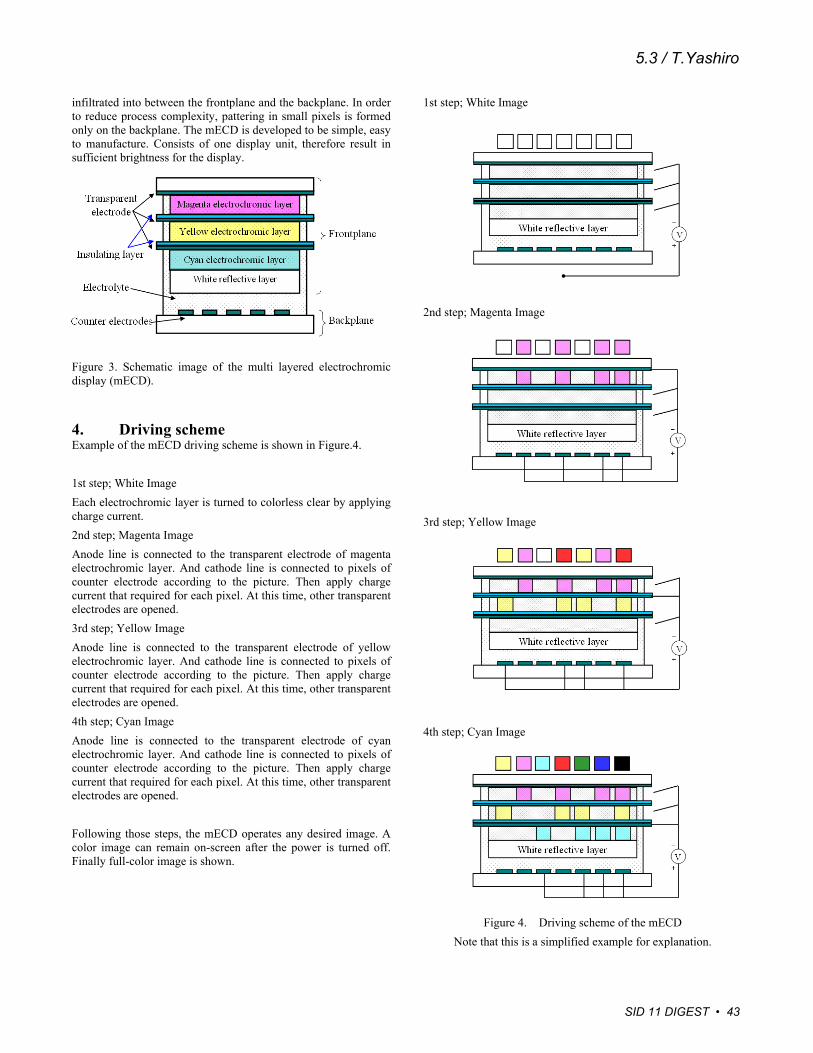
infiltrated into between the frontplane and the backplane. In order to reduce process complexity, pattering in small pixels is formed only on the backplane. The mECD is developed to be simple, easy to manufacture. Consists of one display unit, therefore result in sufficient brightness for the display.
Figure 3. Schematic image of the multi layered electrochromic display (mECD).
4. Driving scheme Example of the mECD driving scheme is shown in Figure.4. 1st step; White Image Each electrochromic layer is turned to colorless clear by applying charge current. 2nd step; Magenta Image Anode line is connected to the transparent electrode of magenta electrochromic layer. And cathode line is connected to pixels of counter electrode according to the picture. Then apply charge current that required for each pixel. At this time, other transparent electrodes are opened. 3rd step; Yellow Image Anode line is connected to the transparent electrode of yellow electrochromic layer. And cathode line is connected to pixels of counter electrode according to the picture. Then apply charge current that required for each pixel. At this time, other transparent electrodes are opened. 4th step; Cyan Image Anode line is connected to the transparent electrode of cyan electrochromic layer. And cathode line is connected to pixels of counter electrode according to the picture. Then apply charge current that required for each pixel. At this time, other transparent electrodes are opened. Following those steps, the mECD operates any desired image. A color image can remain on-screen after the power is turned off. Finally full-color image is shown.
1st step; White Image 2nd step; Magenta Image 3rd step; Yellow Image 4th step; Cyan Image
Figure 4. Driving scheme of the mECD Note that this is a simplified example for explanation.
SID 11 DIGEST • 43
5.3 / T.Yashiro
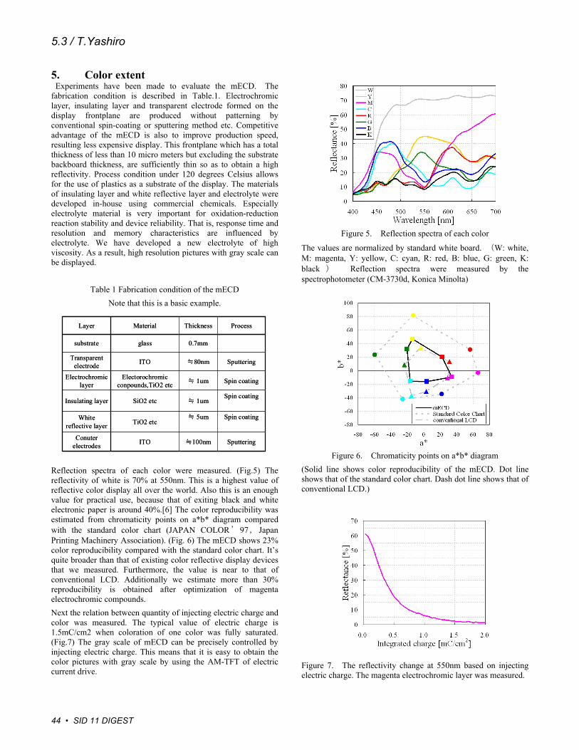
5. Color extent Experiments have been made to evaluate the mECD. The fabrication condition is described in Table.1. Electrochromic layer, insulating layer and transparent electrode formed on the display frontplane are produced without patterning by conventional spin-coating or sputtering method etc. Competitive advantage of the mECD is also to improve production speed, resulting less expensive display. This frontplane which has a total thickness of less than 10 micro meters but excluding the substrate backboard thickness, are sufficiently thin so as to obtain a high reflectivity. Process condition under 120 degrees Celsius allows for the use of plastics as a substrate of the display. The materials of insulating layer and white reflective layer and electrolyte were developed in-house using commercial chemicals. Especially electrolyte material is very important for oxidation-reduction reaction stability and device reliability. That is, response time and resolution and memory characteristics are influenced by electrolyte. We have developed a new electrolyte of high viscosity. As a result, high resolution pictures with gray scale can be displayed.
Table 1 Fabrication condition of the mECD Note that this is a basic example.
Reflection spectra of each color were measured. (Fig.5) The reflectivity of white is 70% at 550nm. This is a highest value of reflective color display all over the world. Also this is an enough value for practical use, because that of exiting black and white electronic paper is around 40%.[6] The color reproducibility was estimated from chromaticity points on a*b* diagram compared with the standard color chart (JAPAN COLOR’97,Japan Printing Machinery Association). (Fig. 6) The mECD shows 23% color reproducibility compared with the standard color chart. It’s quite broader than that of existing color reflective display devices that we measured. Furthermore, the value is near to that of conventional LCD. Additionally we estimate more than 30% reproducibility is obtained after optimization of magenta electrochromic compounds. Next the relation between quantity of injecting electric charge and color was measured. The typical value of electric charge is 1.5mC/cm2 when coloration of one color was fully saturated. (Fig.7) The gray scale of mECD can be precisely controlled by injecting electric charge. This means that it is easy to obtain the color pictures with gray scale by using the AM-TFT of electric current drive.
Figure 5. Reflection spectra of each color
The values are normalized by standard white board. (W: white, M: magenta, Y: yellow, C: cyan, R: red, B: blue, G: green, K: black ) Reflection spectra were measured by the spectrophotometer (CM-3730d, Konica Minolta)
Spin coating≒ 1umSiO2 etcInsulating layer
ITO
TiO2 etc
Electorochromicconpounds,TiO2 etc
ITO
glass
Material
Conuterelectrodes
White reflective layer
Electrochromic layer
Transparent electrode
substrate
Layer
Sputtering≒100nm
Spin coating≒ 5um
Spin coating≒ 1um
Sputtering≒80nm
0.7mm
ProcessThickness
Spin coating≒ 1umSiO2 etcInsulating layer
ITO
TiO2 etc
Electorochromicconpounds,TiO2 etc
ITO
glass
Material
Conuterelectrodes
White reflective layer
Electrochromic layer
Transparent electrode
substrate
Layer
Sputtering≒100nm
Spin coating≒ 5um
Spin coating≒ 1um
Sputtering≒80nm
0.7mm
ProcessThickness
Figure 6. Chromaticity points on a*b* diagram (Solid line shows color reproducibility of the mECD. Dot line shows that of the standard color chart. Dash dot line shows that of conventional LCD.) Figure 7. The reflectivity change at 550nm based on injecting electric charge. The magenta electrochromic layer was measured.
44 • SID 11 DIGEST
5.3 / T.Yashiro
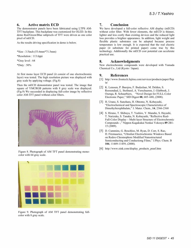
6. Active matrix ECD The demonstrator panels have been fabricated using LTPS AM-TFT backplane. This backplane was customized for OLED. In this demo Red/Green/Blue subpixels of TFT were driven as one color pixel of mECD. As the results driving specification in demo is below. *Size : 3.5inch (53.6mm*71.5mm) *Resolution : 113.6ppi *Gray level : 64 *Duty : 50% At first mono layer ECD panel (it consist of one electrochromic layer) was tested. The high resolution picture was displayed with gray scale by applying voltage. (Fig.8) Then the mECD demonstrator panel was tested. The image that square of YMCRGB patterns with 8 grey scale was displayed. (Fig.9) We succeeded in displaying full-color image by reflective color AM-TFT panel without color filters.
7. Conclusion We have developed a full-color reflective AM display (mECD) without color filter. With fewer elements, the mECD is thinner, lighter and less costly than existing devices and the reduced light loss provides a brighter appearance. In addition, light weight and flexible plastic substrates can be adopted because process temperature is low enough. It is expected that the real electric paper (it substitute for printed paper) come true by this technology. Additionally the mECD cost potential can accelerate practical use.
8. Acknowledgments New electrochromic compounds were developed with Yamada Chemical Co., Ltd (Kyoto / Japan).
9. References [1] http://www.frontech.fujitsu.com/services/products/paper/flep
ia/
[2] K. Lenssen, P. Baesjou, F. Budzelaar, M. Delden, S. Roosendaal, L. Stofmeel, A. Verschueren, J. Glabbeek, J. Osenga, R. Schuurbiers, “Novel Design for FULL-Color Electronic Paper,” SID Digest 08, 685–688, (2008).
[3] H. Urano, S. Sunohara, H. Ohtomo, N. Kobayashi, “Electrochemical and Spectroscopic Characteristics of Dimethylterephthalate,” J. Mater. Chem., 14, 2366-2368
[4] S. Hirano, T. Shibuya, T. Yashiro, Y. Manabe, S. Hayashi, T. Narizuka, S. Tanaka, N. Kobayashi, “Reflective Real-Full-Color Display – Multi-layer Structure of Electrochromic Compounds -,” Nippon Kagakukai Nenkai Yokosyu 89 2B1-15 (2009).
[5] D. Cummins, G. Boschloo, M. Ryan, D. Corr, S. Rao, D. Fitzmaurice, “Ultrafast Electrochromic Windows Based on Redox-Chromophore Modified Nanostructured Semiconducting and Conductiong Films,” J.Phys. Chem. B 104, 11449-11459, (2000).
[6] http://www.eink.com/display_products_pearl.htm Figure 8. Photograph of AM TFT panel demonstrating mono-color with 64 gray scale.
Figure 9. Photograph of AM TFT panel demonstrating full-color with 8 gray scale.
SID 11 DIGEST • 45
5.3 / T.Yashiro