52317 VM-405PBBD2 MM52.191.195.192/files/Manuals/VM405-PBBD2-52317.pdf · The contents of this...
51
VM-405 PBBD2 TK 52317-E-1-MM (Rev. 1, 2/09) Copyright © 2004 Thermo King Corp., Minneapolis, MN, U.S.A. Printed in U.S.A.
Transcript of 52317 VM-405PBBD2 MM52.191.195.192/files/Manuals/VM405-PBBD2-52317.pdf · The contents of this...

VM-405 PBBD2TK 52317-E-1-MM (Rev. 1, 2/09)
Copyright© 2004 Thermo King Corp., Minneapolis, MN, U.S.A.Printed in U.S.A.

The contents of this manual covers information related to the VM-405 PBBD2 unit.For further information, refer to…
VM-405 PBBD2 Operating Manual TK 52318-E-1-OP
The information in this manual is provided to assist owners, operators and service people in the proper upkeepand maintenance of Thermo King units.
This manual is published for informational purposes only and the information so provided should not be consideredas all-inclusive or covering all contingencies. If further information is required, Thermo King Corporation should beconsulted.
Sale of product shown in this manual is subject to Thermo King’s terms and conditions including, but not limited to,the Thermo King Limited Express Warranty. Such terms and conditions are available upon request.
Thermo King’s warranty will not apply to any equipment which has been “so repaired or altered outside the manu-facturer’s plants as, in the manufacturer’s judgment, to effect its stability.”
No warranties, express or implied, including warranties of fitness for a particular purpose or merchantabil-ity, or warranties arising from course of dealing or usage of trade, are made regarding the information, rec-ommendations, and descriptions contained herein. Manufacturer is not responsible and will not be heldliable in contract or in tort (including negligence) for any special, indirect or consequential damages,including injury or damage caused to vehicles, contents or persons, by reason of the installation of anyThermo King product or its mechanical failure.

Recover RefrigerantAt Thermo King, we recognize the need to preserve the environ-ment and limit the potential harm to the ozone layer that canresult from allowing refrigerant to escape into the atmosphere.
We strictly adhere to a policy that promotes the recovery andlimits the loss of refrigerant into the atmosphere.
In addition, service personnel must be aware of Federal regula-tions concerning the use of refrigerants and the certification oftechnicians. For additional information on regulations and tech-nician certification programs, contact your local THERMO KINGdealer.
WARNING: Use ONLY Polyol Ester based refrigeration compressor oil (TK P/N 203-513).
DO NOT use Polyol Ester based oil in standard Thermo King units.
DO NOT mix Polyol Ester and standard synthetic compressor oils.
Keep Polyol Ester compressor oil in tightly sealed containers. If Polyol Ester oil becomescontaminated with moisture or standard oils, dispose of properly—DO NOT USE!
WARNING: When servicing Thermo King R-404A units, use only those service toolscertified for and dedicated to R-404A refrigerant and Polyol Ester compressor oils.
Residual non-HFC refrigerants or oils will contaminate R-404A systems.
R-404A


Table of Contents
Safety Precautions . . . . . . . . . . . . . . . . . . . . . . . . . . . . . . . . . . . . . . . . . . . . . . . . . . . . . . . . . . . . . . . . . . . . . . . . . i
Specifications . . . . . . . . . . . . . . . . . . . . . . . . . . . . . . . . . . . . . . . . . . . . . . . . . . . . . . . . . . . . . . . . . . . . . . . . . . . . .1
Maintenance Inspection Schedule . . . . . . . . . . . . . . . . . . . . . . . . . . . . . . . . . . . . . . . . . . . . . . . . . . . . . . . . . . . . .3
Unit Description . . . . . . . . . . . . . . . . . . . . . . . . . . . . . . . . . . . . . . . . . . . . . . . . . . . . . . . . . . . . . . . . . . . . . . . . . . . .5Defrost Timer. . . . . . . . . . . . . . . . . . . . . . . . . . . . . . . . . . . . . . . . . . . . . . . . . . . . . . . . . . . . . . . . . . . . . . . . . . . . .5Protection Features . . . . . . . . . . . . . . . . . . . . . . . . . . . . . . . . . . . . . . . . . . . . . . . . . . . . . . . . . . . . . . . . . . . . . . . .5Operation. . . . . . . . . . . . . . . . . . . . . . . . . . . . . . . . . . . . . . . . . . . . . . . . . . . . . . . . . . . . . . . . . . . . . . . . . . . . . . . .5
Operating Instructions . . . . . . . . . . . . . . . . . . . . . . . . . . . . . . . . . . . . . . . . . . . . . . . . . . . . . . . . . . . . . . . . . . . . . .7Starting the Unit. . . . . . . . . . . . . . . . . . . . . . . . . . . . . . . . . . . . . . . . . . . . . . . . . . . . . . . . . . . . . . . . . . . . . . . . . . .7Electronic Controls . . . . . . . . . . . . . . . . . . . . . . . . . . . . . . . . . . . . . . . . . . . . . . . . . . . . . . . . . . . . . . . . . . . . . . . .8
Electrical Maintenance . . . . . . . . . . . . . . . . . . . . . . . . . . . . . . . . . . . . . . . . . . . . . . . . . . . . . . . . . . . . . . . . . . . . .13Electric Box . . . . . . . . . . . . . . . . . . . . . . . . . . . . . . . . . . . . . . . . . . . . . . . . . . . . . . . . . . . . . . . . . . . . . . . . . . . . .13P.C. Board. . . . . . . . . . . . . . . . . . . . . . . . . . . . . . . . . . . . . . . . . . . . . . . . . . . . . . . . . . . . . . . . . . . . . . . . . . . . . .14Connectors . . . . . . . . . . . . . . . . . . . . . . . . . . . . . . . . . . . . . . . . . . . . . . . . . . . . . . . . . . . . . . . . . . . . . . . . . . . . .14Fuses. . . . . . . . . . . . . . . . . . . . . . . . . . . . . . . . . . . . . . . . . . . . . . . . . . . . . . . . . . . . . . . . . . . . . . . . . . . . . . . . . .14Relays . . . . . . . . . . . . . . . . . . . . . . . . . . . . . . . . . . . . . . . . . . . . . . . . . . . . . . . . . . . . . . . . . . . . . . . . . . . . . . . . .15Troubleshooting Cab Control Box M13 . . . . . . . . . . . . . . . . . . . . . . . . . . . . . . . . . . . . . . . . . . . . . . . . . . . . . . . .16
Defrost Maintenance . . . . . . . . . . . . . . . . . . . . . . . . . . . . . . . . . . . . . . . . . . . . . . . . . . . . . . . . . . . . . . . . . . . . . . .19Defrost Description . . . . . . . . . . . . . . . . . . . . . . . . . . . . . . . . . . . . . . . . . . . . . . . . . . . . . . . . . . . . . . . . . . . . . . 19Defrost Components . . . . . . . . . . . . . . . . . . . . . . . . . . . . . . . . . . . . . . . . . . . . . . . . . . . . . . . . . . . . . . . . . . . . . .19Testing the Defrost System . . . . . . . . . . . . . . . . . . . . . . . . . . . . . . . . . . . . . . . . . . . . . . . . . . . . . . . . . . . . . . . . .20
Refrigeration Maintenance . . . . . . . . . . . . . . . . . . . . . . . . . . . . . . . . . . . . . . . . . . . . . . . . . . . . . . . . . . . . . . . . . .21Charging an Evacuated Unit by Weight . . . . . . . . . . . . . . . . . . . . . . . . . . . . . . . . . . . . . . . . . . . . . . . . . . . . . . .21High Pressure Cutout Switch . . . . . . . . . . . . . . . . . . . . . . . . . . . . . . . . . . . . . . . . . . . . . . . . . . . . . . . . . . . . . . .22
Refrigeration Service Operations. . . . . . . . . . . . . . . . . . . . . . . . . . . . . . . . . . . . . . . . . . . . . . . . . . . . . . . . . . . . .23Compressor. . . . . . . . . . . . . . . . . . . . . . . . . . . . . . . . . . . . . . . . . . . . . . . . . . . . . . . . . . . . . . . . . . . . . . . . . . . . .23Condenser Coil . . . . . . . . . . . . . . . . . . . . . . . . . . . . . . . . . . . . . . . . . . . . . . . . . . . . . . . . . . . . . . . . . . . . . . . . . .23Filter Drier . . . . . . . . . . . . . . . . . . . . . . . . . . . . . . . . . . . . . . . . . . . . . . . . . . . . . . . . . . . . . . . . . . . . . . . . . . . . . .23Evaporator Assy . . . . . . . . . . . . . . . . . . . . . . . . . . . . . . . . . . . . . . . . . . . . . . . . . . . . . . . . . . . . . . . . . . . . . . . . .24High Pressure Cutout (HPCS). . . . . . . . . . . . . . . . . . . . . . . . . . . . . . . . . . . . . . . . . . . . . . . . . . . . . . . . . . . . . . .24Low Pressure Cutout Switch . . . . . . . . . . . . . . . . . . . . . . . . . . . . . . . . . . . . . . . . . . . . . . . . . . . . . . . . . . . . . . . .24Hot Gas Solenoid Valve . . . . . . . . . . . . . . . . . . . . . . . . . . . . . . . . . . . . . . . . . . . . . . . . . . . . . . . . . . . . . . . . . . .25Low Side Pumpdown Procedure . . . . . . . . . . . . . . . . . . . . . . . . . . . . . . . . . . . . . . . . . . . . . . . . . . . . . . . . . . . . .25Compressor Pumpdown Procedures . . . . . . . . . . . . . . . . . . . . . . . . . . . . . . . . . . . . . . . . . . . . . . . . . . . . . . . . .25Installing and Purging a Gauge Manifold Equipped with Low Loss Fittings . . . . . . . . . . . . . . . . . . . . . . . . . . . .26Removing the Gauge Manifold . . . . . . . . . . . . . . . . . . . . . . . . . . . . . . . . . . . . . . . . . . . . . . . . . . . . . . . . . . . . . .26Setting The CPR Valve . . . . . . . . . . . . . . . . . . . . . . . . . . . . . . . . . . . . . . . . . . . . . . . . . . . . . . . . . . . . . . . . . . .26
Table of Contents (continued)
Structural Maintenance . . . . . . . . . . . . . . . . . . . . . . . . . . . . . . . . . . . . . . . . . . . . . . . . . . . . . . . . . . . . . . . . . . . . 29Unit Inspection . . . . . . . . . . . . . . . . . . . . . . . . . . . . . . . . . . . . . . . . . . . . . . . . . . . . . . . . . . . . . . . . . . . . . . . . . 29Evaporator Coil . . . . . . . . . . . . . . . . . . . . . . . . . . . . . . . . . . . . . . . . . . . . . . . . . . . . . . . . . . . . . . . . . . . . . . . . . 29Condenser Coil . . . . . . . . . . . . . . . . . . . . . . . . . . . . . . . . . . . . . . . . . . . . . . . . . . . . . . . . . . . . . . . . . . . . . . . . . 29Unit Mounting Bolts . . . . . . . . . . . . . . . . . . . . . . . . . . . . . . . . . . . . . . . . . . . . . . . . . . . . . . . . . . . . . . . . . . . . . . 29
Mechanical Diagnosis . . . . . . . . . . . . . . . . . . . . . . . . . . . . . . . . . . . . . . . . . . . . . . . . . . . . . . . . . . . . . . . . . . . . . 31
Electrical Mechanical Diagnosis . . . . . . . . . . . . . . . . . . . . . . . . . . . . . . . . . . . . . . . . . . . . . . . . . . . . . . . . . . . . 33
Refrigeration Diagnosis . . . . . . . . . . . . . . . . . . . . . . . . . . . . . . . . . . . . . . . . . . . . . . . . . . . . . . . . . . . . . . . . . . . 37
Wiring Diagrams and Schematic Index . . . . . . . . . . . . . . . . . . . . . . . . . . . . . . . . . . . . . . . . . . . . . . . . . . . . . . . 39

Safety Precautions
GENERAL PRACTICES
1. ALWAYS WEAR GOGGLES OR SAFETYGLASSES. Refrigerant liquid, refrigeration oil, andbattery acid can permanently damage the eyes (see FirstAid under Refrigeration Oil).
2. Never operate the unit with the compressor dischargevalve closed.
3. Keep your hands, clothing and tools clear of the fansand belts when the unit is running. This should also beconsidered when opening and closing the compressorservice valves.
4. Make sure gauge manifold hoses are in good condition.Never let them come in contact with a belt, fan motorpulley, or any hot surface.
5. Never apply heat to a sealed refrigeration system orcontainer.
6. Fluorocarbon refrigerants, in the presence of an openflame or electrical short, produce toxic gases that aresevere respiratory irritants capable of causing death.
7. Make sure all mounting bolts are tight and are of cor-rect length for their particular application.
8. Use extreme caution when drilling holes in the unit.The holes may weaken structural components, andholes drilled into electrical wiring can cause fire orexplosion.
9. Use caution when working around exposed coil fins.The fins can cause painful lacerations.
10. Use caution when working with a refrigerant or refrig-eration system in any closed or confined area with alimited air supply (for example, a truck box or garage).Refrigerant tends to displace air and can cause oxygendepletion resulting in suffocation and possible death.
11. EPA Section 608 Certification is needed to work onrefrigeration systems.
REFRIGERANT
Although fluorocarbon refrigerants are classified as saferefrigerants, certain precautions must be observed whenhandling them or servicing a unit in which they are used.When exposed to the atmosphere from the liquid state, fluo-rocarbon refrigerants evaporator rapidly, freezing anythingthey contact.
First Aid
In the event of frost bite, the objectives of First Aid are toprotect the frozen area from further injury, to warm theaffected area rapidly and to maintain respiration.
• EYES: For contact with liquid, immediately flush eyeswith large amounts of water and get prompt medicalattention.
• SKIN: Flush area with large amounts of lukewarmwater. Do not apply heat. Remove contaminated cloth-ing and shoes. Wrap burns with dry, sterile, bulkydressing to protect from infection/injury. Get medicalattention. Wash contaminated clothing before reuse.
• INHALATION: Move victim to fresh air and use CPRif necessary. Stay with victim until arrival of emer-gency medical personnel.
REFRIGERATION OIL
Avoid refrigeration oil contact with the eyes. Avoid pro-longed or repeated contact of refrigeration oil with skin orclothing. Wash thoroughly after handling refrigeration oil toprevent irritation.
First Aid
In case of eye contact, immediately flush with plenty ofwater for at least 15 minutes. Wash skin with soap andwater. CALL A PHYSICIAN.
i

Safety Precautions (Rev. 1, 2/09)
ELECTRICAL HAZARDS
High Voltage
When servicing or repairing a refrigeration unit, the possi-bility of serious or even fatal injury from electrical shockexists. Extreme care must be used when working with anoperating refrigeration unit. Lethal voltage potentials canexist on connections in the high voltage tray of the controlbox.
Precautions
1. When working on high voltage circuits on the refrigera-tion unit, do not make any rapid moves. If a tool drops,do not grab for it. People do not contact high voltagewires on purpose. It occurs from an unplanned move-ment.
2. Use tools with insulated handles that are in good condi-tion. Never hold metal tools in your hand if exposed,energized conductors are within reach.
3. Treat all wires and connections as high voltage until ameter and wiring diagram show otherwise.
4. Never work alone on high voltage circuits on the refrig-eration unit, another person should always be standingby in the event of an accident to shut off the refrigera-tion unit and to aid a victim.
5. Have electrically insulated gloves, cable cutters andsafety glasses available in the immediate vicinity in theevent of an accident.
ii
First Aid
IMMEDIATE action must be initiated after a person hasreceived an electrical shock. Obtain immediate medicalassistance if available.
The source of shock must be immediately removed byeither shutting down the power or removing the victim fromthe source. If it is not possible to shut off the power, the wireshould be cut with either an insulated instrument (e.g., awooden handled axe or cable cutters with heavy insulatedhandles) or by a rescuer wearing electrically insulatedgloves and safety glasses. Whichever method is used do notlook at the wire while it is being cut. The ensuing flash cancause burns and blindness.
If the victim has to be removed from a live circuit, pull thevictim off with a non-conductive material. Use the victim’scoat, a rope, wood, or loop your belt around the victim’s legor arm and pull the victim off. DO NOT TOUCH the victim.You can receive a shock from current flowing through thevictim’s body. After separating the victim from powersource, check immediately for the presence of a pulse andrespiration. If a pulse is not present, start CPR (Cardio Pul-monary Resuscitation) and call for emergency medicalassistance. If a pulse is present, respiration may be restoredby using mouth-to-mouth resuscitation, but call for emer-gency medical assistance.
Low Voltage
Control circuits used in the refrigeration unit are low volt-age (24 volts dc). This voltage potential is not considereddangerous, but the large amount of current available (over30 amperes) can cause severe burns if shorted or ground.
Do not wear jewelry, watch or rings. These items can shortout electrical circuits and cause severe burns to the wearer.

Specifications
Design Features• M13 Controller
• Digital Thermometer
• Electronic Thermostat, adjustablefrom -26 F to 86 F
• Defrost Timer
• Hot Gas Defrost
• Defrost Termination Switch
• Manual Defrost Switch
• Receiver Tank with Outlet Service Valve
• 2HP Semihermetic Compressor 50/60 Hz
• Compressor Thermal Protection
• Hourmeter
• 100W Lamp Plug
• Draining Heater Wire Resistances
• Electric Resistant Heaters (750 W)
Standby AC Motor
Refrigeration Specifications
CAUTION: When the oil is removed from the compressor, oil level should be noted so that the same level can be maintained in the replacement compressor.
CAUTION: Polyol Ester compressor oil should be used in standard Thermo King units, and PAG-type or mineral oils should not be added to systems using R404A.
Voltage Phase Frequency Horsepower Full Load Current
230/400 3 50/60 Hz 2 14.1/8.1A
Total System Oil Charge 1250 cc (42.2 oz.)Compressor Oil Type Polyol Ester P/N 203513Refrigerant Charge and Type 2.2 kg (4.8 lb) R-404ADefrost Method Hot GasDefrost Termination Switch: Opens
Closes8.9 ± 3C (48 ± 5.4 F)2.2 ± 3C (36 ± 5.4 F)
High Pressure Cutout Switch OpensCloses
450 ± 10 psi375 ± 10 psi
Low Pressure Cutout Switch OpensCloses
5 to 11 inch. Vacuum27.6 to 48.3 kPa (4 to 7 psi)
Defrost Timer: Initiation Interval From 1 minute to 10 hoursTermination Interval When Defrost Termination Switch opens
1

Specifications (Rev. 1, 2/09)
Condenser & Evaporator Fan Motors
Fuses
Hot Gas Solenoid Coils
Heaters
Voltage Number Power Ratingin W. Full Load RPM Full Load Current
Evaporator 26 V 2 100 2800 5.2 ACondensor 26 V 1 180 2800 8.9 A
VoltageEvaporator
fanFuse 1
Evaporator fan
Fuse 2
Condenser fan
Fuse 3
M-13Fuse 4
M-13Fuse 4/1
Transformer Fuse 5
24 V 10 A 10 A 15 A 3 A 3 A 5 A
VoltageExternal
lampFuse 6
External lamp
Fuse 7
24 V 1 A 1 A
Voltage Current Resistance
24 V 1.3 A 20 Ohms
Voltage AC Number Power in W. Full Load Current
220 V 2 750 3.5 A
2

Maintenance Inspection Schedule
First Week Inspection and MaintenanceAFTER FIRST WEEK OF OPERATION:• Tighten the unit and mount bracket mounting bolts
Bi-monthly Annually Inspect/Service These ItemsELECTRICAL
• • Check defrost initiation and termination.
• • Check thermostat cycle sequence.
• • Check operation of protection shutdown circuits.
• Check thermostat and thermometer calibration in 32 F (0 C) ice-water bath.
• Inspect wire harness for damaged wires or connections.REFRIGERATION
• • Check refrigerant level.
• Replace dehydrator.STRUCTURAL
• • Visually inspect unit and refrigerant hoses for fluid leaks.
• • Visually inspect unit for damaged, loose or broken parts.
• • Clean defrost drains.
• • Clean entire unit including evaporator coil and condenser coil.
• • Check all unit mounting bolts, brackets, lines, etc.
3

4

Unit Description
The Thermo King VM 405 PBBD2 refrigeration system is aone-piece nose mounted unit. It uses a semihermetic com-pressor in the condenser section for cooling operation.
The unit is designed for low and medium temperaturesmall-sized compartments. It can cool and defrost on elec-tric compressor operation to refrigerate one compartmentwith R404A. Heating is accomplished by connecting theheating resistances.
The control circuits operate on 24 Vdc rectified from an ACtransformer. Each refrigeration system is protected by highand low pressure cutout switches.
Unit operation is performed from a remote control box. Itincludes an On/Off switch, manual defrost switch, ther-mometer, thermostat, thermostat adjustment, and indicatorlights.
Compressor operation is controlled by the thermostat, ener-gizing the compressor contact during cooling operation.
Defrost: A hot gas solenoid valve provides local heat to theevaporator by means of hot gas from the discharge line. Anelectronic defrost timer can initiate defrost automatically.Defrost is normally terminated by the defrost terminationswitch mounted on the evaporator coil. The defrost cyclecan be terminated by pressing the On/Off switch.
DEFROST TIMER
The defrost timer automatically initiates the defrost cycle atpreset intervals.
The Defrost Timer is powered directly by the standby powersupply. This means that the Defrost Timer is counting when-ever the unit is connected to the main supply (while Klixonis closed), even when the unit is switched off.
PROTECTION FEATURES
• High Pressure Cutout Switch
The High Pressure Cutout Switch is a pressure-sensi-tive switch located in the discharge line. If the dis-charge pressure rises above 450 psi (3100 kPa), theswitch opens the circuit to the PR Relay to stop theunit. When the discharge pressure falls below 375 psi(2600 kPa), the switch closes.
• Low Pressure Cutout Switch
The Low Pressure Cutout Switch is a pressure-sensitiveswitch located in the suction line. If the pressure fallsbelow 5 to 11 inch vacuum, the switch opens the circuitto the PR Relay to stop unit operation. The switchcloses at 4 to 7 psi.
• Overload Relay Protection for Electric Motor
• Overload Relay Protection for heater resistance
• Fuses
• Power Cord LED
• Overload Relay LED
• Thermistor: Disconnects AC motor if its temperaturereaches a threshold value.
OPERATION
General
These units cycle among Heat, Cool and Null to maintainthe box temperature at the thermostat setpoint. The operat-ing modes are: Cool, Null, Heat and Defrost.
The thermostat controls the operation of the unit by energiz-ing and de-energizing the Power Relay PR.
When the Power Relay is energized, the condenser fans arepowered up (as well as the compressor motor).
5

Unit Description (Rev. 1, 2/09)
When the unit is connected to the main supply, the externallamp is powered up by 110 V.
Operating Modes
Cool
The thermostat energizes the Power Relay at box tempera-tures higher than setpoint. The thermostat keeps the PowerRelay energized while the box temperature is higher than4 F (2.2 C) above setpoint. The Power Relay energizes theevaporator and condenser fan relays, the drain heaters andthe compressor contactor. The fans and the compressor runand the unit cools.
Null
The thermostat shifts from Cool to Null at box temperatureslower than setpoint. The thermostat shifts the unit fromCool to Heat at 4 F (2.2 C) below the setpoint. The thermo-stat shifts the unit from Heat to Null at setpoint.
Heat
The thermostat shifts the unit to Heat at temperatures morethan 4 F (2.2 C) below the thermostat setpoint. The thermo-stat keeps the unit running in Heat until the temperaturereaches the thermostat setpoint.
When the unit is in Heat mode, the thermostat drives theheater contactor, the evaporator fans and the electric resis-tant heaters, and the unit heats.
Defrost
The Defrost cycle can be initiated any time the evaporatorcoil temperature is below 36 F. Defrost is initiated automati-cally by the defrost timer, or manually by pressing the man-ual defrost switch.
When the Power Relay is energized, the drain heaters areactivated and the defrost relay energizes the Solenoid ValvePS to route hot refrigerant gas to the evaporator. The defrostrelay also interrupts power to the fan relays to stop the evap-orator and condenser fans during defrost.
6
The Defrost cycle will continue until the evaporator coiltemperature rises to 48 F, causing the defrost terminationswitch to open. Defrost cycle can also be terminated bypressing the On/Off switch twice.
Operating Modes
1. Temperature Drop2. Setpoint3. 4 F4. Temperature Rise5. 4 F6. Cool7. Null8. Heat
1
2
3
4
5
6
7
8 ANA144

Operating Instructions
Leaks
Inspect for refrigerant leaks and worn refrigerant lines.
Electrical
Electrical connections should be securely fastened. Wiresand terminals should be free of corrosion, cracks or mois-ture.
Defrost Drain
Check the defrost drain hose and fittings to be sure that theyare open so condensation can run out during defrosting.Check the bottom end of the drain hose to be sure that it isnot plugged or crushed.
Structural
Visually check for physical damage.
Sightglass
Check for proper refrigerant charge level.
STARTING THE UNIT
Electric Operation
1. Connect the external power supply to the power recep-tacle. Make sure that the power supply voltage is cor-rect for the unit. The Power Cord LED must be ON.
2. Press the On/Off Switch in the Control Box. The On/Off LED must be ON.
3. Adjust the thermostat setting.
After Start Inspection
Thermostat
Dial the thermostat setting above and below the box temperature to check thermostat operation.
Pre-Cooling
With the thermostat set at the desired temperature, allow theunit to run for one-half to one hour before loading the con-tainer. Pre-cooling will remove residual body heat andmoisture from the box interior and provide a good test of therefrigeration system.
Defrost
When the unit has finished pre-cooling, the container interior (evaporator temperature dropped below 2.2 C/36 F), initiate a defrost cycle with the manual defrost switch. The defrost cycle should end automatically.
Loading Procedure
1. Be sure the unit is OFF before opening the door to min-imize frost accumulation on the evaporator coil andheat gain inside the box.
2. Spot check and record load temperature while loading.Especially note any off-temperature product.
3. Load product so that there is adequate space for air cir-culation completely around the load. DO NOT blockthe evaporator inlet or outlet.
4. Products should be pre-cooled before loading. ThermoKing units are designed to maintain loads at a consis-tent temperature, NOT to cool down hot loads.
7

Operating Instructions (Rev. 1, 2/09)
Post Load Procedure
To remove excess moisture before storage:
1. Be sure all doors are closed and locked.
2. Adjust the thermostat to the desired temperature set-point.
3. Start the unit.
4. Half an hour after loading, defrost the unit by momen-tarily pressing the Manual Defrost switch. If the coiltemperature drops below 36 F, the unit will defrost. Thedefrost cycle should stop automatically.
ELECTRONIC CONTROLS
Units are equipped with an M13 controller. The controllerregulates unit functions and displays operating informationquickly and accurately.
WARNING: Do not operate the unit until you arecompletely familiar with the display screen andfunction of each control key.
The M13 controller automatically displays the return airtemperature; provides temperature control from -26 to 86 F(-32 to 30 C) in 2 F (1 C) increments; and automaticallydefrosts every three hours.
NOTE: The defrost interval is set at the factory. The inter-val may be reset, if needed, by a certified Thermo Kingtechnician.
8

Operating Instructions (Rev. 1, 2/09)
Figure 1: M13 Controller
Table 1: M13
1. ON Indicator Light 5. Defrost Indicator Light
2. ON-OFF Key 6. Manual Defrost Key
3. Power Cord Indicator Light 7. Celsius Led Indicator
4. Unit Operation Indicator Light 8. Fahrenheit Led Indicator
5 6
2
1
3
4
9
Components
9. AC Overload Led 13 Thermostat Dial
10. Setpoint Led 14. Digital Display
11. Setpoint Key Indicator
12. Setpoint Key
7
138
9
11
12
AKB721014

Operating Instructions (Rev. 1, 2/09)
M13 Unit Controls
On-Off Key Press this key to turn the unit ON and OFF.When the unit has been stopped by the HEAT or COOLOverload Relay, press this key to restart the unit.
ON Indicator When this light is on, it indicates that the unitis turned ON. When this light is off, it indicates that the unitis turned OFF.
Power Cord Indicator When this light is on, it indicatesthat the unit is connected to an AC voltage power supply.
Unit Operation Indicator Light When this light is on, itindicates that the unit is operating. This light indicates bothcooling and heating modes. If the light is green, the unit iscooling. If the light is red, the unit is heating. When the unitis stopped by the thermostat, HPCO, or LPCO, the UnitOperation Indicator Light must be OFF and the ON Indica-tor must remain ON.
Manual Defrost Key Press this key to start a defrost cycle.The unit will not defrost unless the defrost terminationswitch is closed and the evaporator coil temperature isbelow 36 F (2 C).
Defrost Indicator When this light is on, it indicates that theunit is in defrost.
Digital Display This display is active only when the unit isturned on. The thermometer reading (return air sensor tem-perature) normally appears on the display.
Celsius Indicator When this light is on, it indicates that thetemperature is being displayed in degrees Celsius.
Fahrenheit Indicator When this light is on, it indicates thatthe temperature is being displayed in degrees Fahrenheit.
10
AC Overload Indicator When this light is on, it indicatesthat the overload relay has opened and the unit has beenstopped. This indicator must be reset by pressing the On-OffKey after allowing time for the overload relay to cool.
Setpoint Key Press this key to make the thermostat setpointappear on the digital display. The thermostat setpoint willremain on the display for 10 to 15 seconds after the key isreleased. This gives the operator time to adjust the thermo-stat setpoint.
Thermostat Dial Turn this dial to adjust the thermostat set-point.
NOTE: The Thermostat Dial will change the thermostatsetpoint without pressing the Setpoint Key.
M13 Display Information
With the unit or the controller OFF, the display screen willbe dark—nothing will appear on the display screen. Whenthe unit ON/OFF key is pressed ON, the Unit OperationIndicator Light will be lit.
The unit will display the return air temperature or the set-point temperature on the display screen, depending on thecurrent operating mode.
When the unit is switched OFF, the screen is blank and theUnit Operation Indicator Light goes OFF.
M13 Display Operating Data
During normal operation, the return air temperature remainson the display screen. To display the setpoint, press the set-point key.
NOTE: The setpoint will remain on the display screen for10 seconds after the setpoint key has been pressed.

Operating Instructions (Rev. 1, 2/09)
M13 Initiate Manual Defrost
You may initiate a manual defrost anytime the evaporatorcoil temperature is below 36 F (2 C).
1. Press the manual defrost key. The defrost will light,indicating that the unit is defrosting. The unit will auto-matically return to the proper operating mode when thedefrost cycle is finished. The unit will return to coolingmode automatically when the coil temperature reaches48 F (8.9 C).
2. To end the defrost cycle before automatic termination,press the ON/OFF key to OFF.
M13 Enter The Setpoint
The setpoint can be easily changed once you are familiarwith the controls.
1. Press the setpoint key and the setpoint temperature isdisplayed on the screen.
2. Observe the controller display and turn the thermostatdial to the desired setpoint temperature.
3. Release the setpoint key. The return air temperatureshould appear on the display screen after 10 seconds.
CAUTION: Do not accidentally move the thermo-stat dial. The setpoint temperature can be changedby moving the dial without pressing the setpointkey.
11

12

Electrical Maintenance
ELECTRIC BOX
P.C. Board P.E.-9
ANA145
13

Electrical Maintenance (Rev. 1, 2/09)
P.C. BOARD
All Printed Circuit Boards manufactured by Thermo Kingcan be easily identified by the P/N stamped on them.
CONNECTORS
All connector codes (C-1, C-2, C-3, and C-4) are stampedon the P.C. Board. Pins on connectors are numberedcounter-clockwise. (C-1 and C-2: 6 pin; C-3 and C-4: 8 pin).
Electric Box (with
14
P.C. Board P.E.-9)
FUSES
The fuses 1, 2, 3, and 4 are located on the P.C. Board.
Fuse 1: Protects evaporator fan (EF1) from overload.
Fuse 2: Protects evaporator fan (EF2) from overload.
Fuse 3: Protects condenser fan motor and defrost solenoidcoil (when defrost is energized) from overload.
Fuse 4: Protects Cab Control Box. It is located on the P.C.Board.
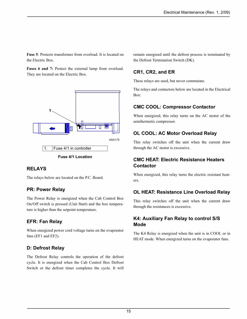
Fuse 4/1: Protects Cab Control box from overload. It islocated inside the Cab Control box. Remove the rear coverto access the fuse.
Electrical Maintenance (Rev. 1, 2/09)
Fuse 5: Protects transformer from overload. It is located onthe Electric Box.
Fuses 6 and 7: Protect the external lamp from overload.They are located on the Electric Box.
Fuse 4/1 Location
RELAYS
The relays below are located on the P.C. Board.
PR: Power Relay
The Power Relay is energized when the Cab Control BoxOn/Off switch is pressed (Unit Start) and the box tempera-ture is higher than the setpoint temperature.
EFR: Fan Relay
When energized power cord voltage turns on the evaporatorfans (EF1 and EF2).
D: Defrost Relay
The Defrost Relay controls the operation of the defrostcycle. It is energized when the Cab Control Box DefrostSwitch or the defrost timer completes the cycle. It will
1. Fuse 4/1 in controller
1
ASA175
15
remain energized until the defrost process is terminated bythe Defrost Termination Switch (DK).
CR1, CR2, and ER
These relays are used, but never commutate.
The relays and contactors below are located in the ElectricalBox:
CMC COOL: Compressor Contactor
When energized, this relay turns on the AC motor of thesemihermetic compressor.
OL COOL: AC Motor Overload Relay
This relay switches off the unit when the current drawthrough the AC motor is excessive.
CMC HEAT: Electric Resistance Heaters Contactor
When energized, this relay turns the electric resistant heat-ers.
OL HEAT: Resistance Line Overload Relay
This relay switches off the unit when the current drawthrough the resistances is excessive.
K4: Auxiliary Fan Relay to control S/S Mode
The K4 Relay is energized when the unit is in COOL or inHEAT mode. When energized turns on the evaporator fans.

Electrical Maintenance (Rev. 1, 2/09)
TROUBLESHOOTING THE M13 CONTROLLER
Before starting troubleshooting, verify that the 12/24V selector is placed in the 24V position and check the ground circuitthrough Pin 9 Connector C-9.
Block Diagram M13
IMPORTANT: This troubleshooting only covers M13 functions, and should not be considered as all-inclusive or meant tocover all other electric contingencies.
Symptoms Remedy
Blank display when the On/Off switch is pressed. Check voltage on Pin 2 C-9.Check Fuse 4 located inside the Cab Control Box.Replace Cab Control Box.
Unit is not cooling when the Box Temperature is higher thanthe Setpoint Temperature.
Check voltage on Pin 6 C-9.Replace Cab Control Box.
Unit operation LED if OFF when the unit is cooling. Check voltage on Pin 7 C-9.Replace Cab Control Box.
Defrost cycle is not initiated when the Manual Defrost switchis pressed.
Box temp. must be higher than Setpoint temp.Evap. Coil temp. must be lower than 36 F (Klixon closed).Press the Manual Defrost switch and check voltage on Pin 8C-9.Replace Cab Control Box.
ANA147
16

Electrical Maintenance (Rev. 1, 2/09)
PCRCpC
OCCCRCR
CCCC
PC
R
Defrost LED is OFF when the unit is in Defrost Mode.
Temperature displayed is out of range.
Unit is not working in Electric Mode.
Unit is stopped by the AC OL Relay, but the AC OverloadLED is OFF.Compressor does not run
Power at compressor terminals but does not runCompressor hums but does not run
Check transformerCheck rectifier
Symptoms
17
Check for open circuit on yellow wire, between Pin 4 C-9 andin 2 C-2.heck voltage on Pin 8 C-9.eplace Cab Control Box. heck that the Cab Control Box 12/24V selector is in the 24Vosition. heck the thermostat sensor.
Check the AC Overload Relay (AC Overload LED must beFF).heck the fuses on PCB.heck voltage on Pin 2 C-9.heck voltage on Pin 1 C-9.eplace Cab Control Box.heck voltage on Pin 5 C-9. eplace Cab Control Box.
Check for power at sourceheck for power at plugheck for power at compressor contactorheck for power at overload terminals (contactor closed)heck for power at motor terminals
Replace compressorower source for single phasingheck capacitors
Check for power outputCheck for rectifier output
emedy

18

Defrost Maintenance
DEFROST DESCRIPTION
A defrost cycle can be started by pressing the manualdefrost switch or automatically by the defrost timer, whenthe defrost termination switch is closed and the unit is incool mode.
The defrost cycle operates energizing the Defrost SolenoidCoil (PS) and de-energizing the fan relay, which stops theevaporator and condenser fans.
Energizing the Defrost Solenoid Valve diverts hot gas intothe evaporator coil, melting ice. A defrost terminationswitch de-energizes the defrost relay when evaporator coiltemperature rises above 48 F.
To initiate the defrost cycle, the evaporator coil temperaturemust be below 36 F.
DEFROST COMPONENTS
Defrost Timer Settings
The Defrost timer has two switches and a red, round selec-tor. The timer is set from factory at 4 hours. To change thesetting of the Defrost timer, proceed as follows:
Defrost Timer
The following table can be found on the printed circuitboard:
Choose a range from the timing table and set the A and Bselectors to the desired position.
Example: Setting the A and B selectors to the positions A:↓and B:↓ selects a range of time between 64 and 640 minutes(1 to 10 hours).
The red selector multiplies the minimum value of the cho-sen range by the value at which it is pointing.
If the selector points to position 2: 2 * 64 = 128 minutes(approximately 2 hours).
If the selector points to position 4: 4 * 64 = 256 minutes(approximately 4 hours).
Manual Defrost Switches
A Manual Defrost switch is located in the Cab Control Box.Pressing this switch initiates the defrost cycle if the defrosttermination switch is closed and the unit is in Cool mode.
Defrost Termination Switch (Klixon)
The Defrost Termination switch is mounted in the evapora-tor coil and controls the defrost cycle in response to theevaporator coil temperature. The switch is closed when theevaporator coil temperature is below 36 F, completing thedefrost circuit to ground and preparing the electrical systemfor the defrost cycle.
When the unit does shift into a defrost cycle, the evaporatorand condensor fan stop, and heat from the hot refrigerantgas melts the frost from the evaporator coil. The switchopens and terminates the defrost cycle when the evaporatorcoil temperature rises above 36 F.
AUA0051
Timing Table A B Scale0.25 - 2.5 ↓ ↑ 0.25 to 2.5 minutes1 - 10 ↑ ↓ 1 to 10 minutes8 - 80 ↑ ↑ 8 to 80 minutes64 - 640 ↓ ↓ 1 to 10 hours
19

Defrost Maintenance (Rev. 1, 2/09)
Defrost Relay
The Defrost relay controls operation of the defrost cycle.When the Defrost Timer or the Manual Defrost switch com-pletes the circuit through the defrost termination switch toground, the defrost relay is energized. This energizes theSolenoid Valve and de-energizes the condenser fan.
The defrost relay stays energized until the defrost cycle isterminated by the defrost termination switch or the On/Offswitch is pressed.
Defrost Solenoid Valve
The hot gas valve is an electrical valve that controls theflow of refrigerant through the refrigeration system.
When Solenoid Valve PS is energized, the hot gas valve isopened and it routes hot refrigerant gas to the evaporator.
TESTING THE DEFROST SYSTEM
To test the defrost system, run the unit on Cool until theevaporator coil temperature is below 36 ± 5.4 F and pressthe manual defrost switch.
If the unit doesn’t switch to defrost cycle, proceed to step 1(below).
1. Check the Evaporator Temperature.
Be sure that the evaporator coil temperature is actuallybelow 36 ± 5.4 F, or the unit will not defrost. Use a testthermometer to check the evaporator temperature.
2. Check the defrost termination switch.
If the unit fails to defrost, place a jumper wire betweenboth switch terminals. Press the Manual Defrost switch.
If the unit shifts to Defrost, the defrost terminationswitch is defective.
20
If the unit does not switch to Defrost, check for an opencircuit in the 12 wire. If the 12 wire is not opened, pro-ceed to step 3.
3. Check voltage on PCB terminal of GR (grey) wire.
If voltage is present, proceed to step 4.
4. Check for open circuit on wire GR that goes to CabControl Box (Pin 8 C-9).
If the wire GR is not open, proceed to step 5.
5. Keeping the Manual Defrost switch pressed, checkvoltage on Pin 8 C-9.
If voltage is present on Pin 8 C-9, and the rest of theabove mentioned points are correct, replace the PrintedCircuit Board.
If voltage is not present on Pin 8 C-9, follow Cab Con-trol Box troubleshooting directions.
Defrost Timer Test
The defrost timer initiates the defrost cycle.
1. Verify that the evaporator coil temperature is lowerthan 36 ± 5.4 F, otherwise jump up the Klixon termi-nals.
2. Set the Defrost Timer to approximately 1 minute: A: ↓,B: ↓, red round selector position 4.
3. After approximately 1 minute, the defrost must be initi-ated: Defrost LED, Defrost Relay, and Solenoid Valvemust be activated.

Refrigeration Maintenance
NOTE: The following procedures involve servicing the refrigeration system. Some of these service procedures are regu-lated by Federal, and in some cases, by State and Local laws.
All regulated refrigeration service procedures must be performed by an EPA certified technician, using approved equip-ment and complying with all Federal, State and Local laws.
The liquid line sight glass helps the operator to determine Adding Liquid in the Low Side to
the amount of charge under established operating condi-tions. These units can be damaged by an over-charge ofrefrigerant.The VM-405 PBBD2 compressor for R-404A is filled withPolyol Ester Oil P/N 203513. Refer to Refrigeration Speci-fications for more information.
CHARGING AN EVACUATED UNIT BY WEIGHT
1. Install a gauge manifold. Keep the unit off.
2. Recover the refrigerant and evacuate the system.
3. Place the refrigerant bottle on a scale and attach themanifold’s service line.
4. Purge air from the service line as required. Open thebottle to withdraw liquid.
5. Record total refrigerant and container weight.
6. Check the unit data plate or unit Maintenance Manualfor refrigerant weight required.
7. Midseat the compressor discharge service valve.
8. Open the discharge valve all the way on the gauge man-ifold and begin charging the unit. Refrigerant flow canbe felt as small pulsations on the manifold service line.
9. Watch the scale and close the hand valve at the refriger-ant bottle when the correct charge has been added. Ifrefrigerant flow stops before charging is complete, addliquid to complete charging.
Complete Charging
1. Backseat the discharge service valve. Midseat the suc-tion service valve.
2. Set the bottle to withdraw liquid. Close the manifold’shigh pressure hand valve.
3. Run the unit in cool and read suction pressure.
4. Open the manifold low pressure hand valve to allowliquid to enter and suction pressure to increase approxi-mately 25 psi.
5. When the correct weight has been added, close thehand valve at the refrigerant bottle.
6. Remove the gauge manifold using the correct proce-dure.
7. Use good caps and seals and secure service port capsand valve stem covers before returning the unit to ser-vice.
21

Refrigeration Maintenance (Rev. 1, 2/09)
Checking the Refrigerant Charge
If the unit has an insufficient charge of refrigerant, the evap-orator will be “starved” and the box temperature will riseeven though the unit is operating. Also, an insufficientcharge does not circulate enough oil to properly lubricatethe compressor. The charge may be determined by inspec-tion of the refrigerant through the sight glass with the fol-lowing conditions established:
1. Install gauge manifold set.
2. Run unit on Cool until the thermometer reads 0 F.
3. The discharge or head pressure gauge should read 270psi on the gauge manifold.
NOTE: The condenser coil may have to be partiallycovered in order to reach 270 psi in cool ambients. Inextreme ambient temperatures a head pressure ashigh as 350 psi is acceptable.
4. Under these conditions, the sight glass must indicate afull charge.
HIGH PRESSURE CUTOUT SWITCH
The high pressure cutout switch is located on the checkvalve assembly inside the condenser unit. If the dischargepressure rises above 450 psi on R-404A units, the switchopens the 7A (see unit diagram) circuit, de-energizing thePower Relay.
To test the switch, rework a gauge manifold:
1. Connect the gauge manifold to the compressor dis-charge service valve.
NOTE: Service manifold hoses must have Schradervalve (tube valve) depressors.
2. Set the thermostat well below the box temperature sothat the unit will be on Cool mode.
22
3. Raise the discharge pressure of the compressor byblocking the condenser coil air flow. When the dis-charge pressure gets up to 450 psi on R-404A units, theHigh Pressure Cutout will switch off the unit.
NOTE: The discharge pressure should never beallowed to exceed a pressure of 450 psi.
4. Failure of the high pressure cutout system to stop com-pressor operation should be investigated first by check-ing the control circuit operation and second by HighPressure Cutout switch replacement.
High Pressure Cutout Manifold
1. Relief valve (66-2202)2. O-Ring (33-1015)3. Adapter Tee Weather Head No. 552x3
1
2
3
ANA149

Refrigeration Service Operations
NOTE: It is generally good practice to replace the filter drier whenever the high side is opened or when the low side isopened for an extended period of time.
COMPRESSOR
Removal
1. Pump down the compressor. Front seat suction and dis-charge service valves.
2. Disconnect the discharge and suction hoses.
3. Keep the compressor ports and the suction and dis-charge lines for the compressor covered to prevent con-tamination of system components.
4. Remove the compressor mounting screws. Remove thecompressor.
Installation
NOTE: Any compressor installed in this system mustcontain the proper amount of compressor oil (see theSpecifications section). Always check to make sure thatthe compressor contains the proper amount of oil. Followthe system cleanup procedures to remove old oil from thesystem.
1. Place the compressor in position and install the mount-ing screws and the belt.
2. Connect suction line and discharge line.
3. Pressurize the system and test for leaks.
4. Evacuate the system and recharge.
CONDENSER COILRemoval
1. Recover the refrigerant charge.
2. Remove the condenser cover.
3. Remove the condenser fan.
4. Remove the inlet and liquid lines.
5. Remove mounting screws and nuts.
6. Remove the condenser oil.
Installation
1. Clean the tubes for soldering.
2. Place the coil in the unit and install the screws and nuts.
3. Solder the inlet and liquid line connections.
4. Pressurize the system and test for leaks.
5. Mount condenser fan.
6. Evacuate the system.
7. Recharge the unit.
8. Reinstall the cover.s
FILTER DRIER
Removal
1. Pump down the low side of the system and equalize thepressure to slightly positive.
2. Disconnect the nuts at the ends of the drier.
3. Loosen the mounting hardware and remove the drier.
Installation
1. Place new O-rings in the fittings on the ends of thedrier.
2. Install the new drier and tighten the mounting screwsand nuts.
3. Install and tighten the inlet nut. Hold the drier with aback-up wrench on the hex behind the fitting.
4. Release a small amount of refrigerant to purge the airthrough the drier, and then tighten the outlet nut.
5. Pressurize the system and inspect for leaks. If no leaksare found, open the refrigeration valves and place theunit in operation.
23

Refrigeration Service Operations (Rev. 1, 2/09)
EVAPORATOR ASSY
Removal
1. Pump down the low side and equalize the pressure toslightly positive.
2. Remove evaporator fan motor assy.
3. Disconnect the expansion valve from the distributorand remove the expansion valve.
4. Remove the defrost termination switch.
Installation
1. Install the evaporator fan motor assembly.
2. Install the expansion valve (see drawing below).
3. Install the Low Pressure Cutout.
4. Install the defrost termination switch.
5. Connect refrigeration lines.
6. Pressurize the system and test for leaks. If no leaks arefound, evacuate the system.
7. Connect the evaporator fan motor lead(s). Install theevaporator panel(s).
8. Open the refrigeration valves and place the unit in oper-ation. Check the refrigeration charge and compressoroil and add as required.
Bulb Location
HIGH PRESSURE CUTOUT (HPCS)
Removal
1. Recover the refrigerant charge.
2. Disconnect the wires and remove the switch.
Installation
1. Apply a refrigerant locktite to the threads of the switch.
2. Install and tighten the switch and reconnect the connec-tor.
3. Pressurize the refrigeration system and test for leaks.
4. If no leaks are found, charge the system.
LOW PRESSURE CUTOUT SWITCH
Removal
1. Pump down the low side and stop the unit.
2. Unplug the switch connector and remove the switch.
Installation
1. Apply a refrigerant oil to the threads of the switch.
2. Install and tighten the switch and reconnect the connec-tor.
3. Pressurize the refrigeration system and test for leaks.
4. If no leaks are found, evacuate the low side.
5. Open the receiver tank outlet valve, start the unit andcheck the refrigerant charge.
6. If no leaks are found, evacuate the system.
7. Recharge the unit with refrigerant and check compres-sor oil.
ANA150
24

Refrigeration Service Operations (Rev. 1, 2/09)
HOT GAS SOLENOID VALVE
Removal
1. Recover the refrigerant charge.
2. Disconnect the coil wires.
3. Unsolder the refrigeration lines from the solenoid.
4. Unbolt the solenoid and remove the mounting bracket.
Installation
1. Bolt the solenoid to the mounting bracket.
2. Solder the refrigeration lines and electrical wires to thesolenoid.
3. Pressurize the system and test for leaks.
4. Evacuate and recharge the system.
LOW SIDE PUMPDOWN PROCEDURE
1. Install a calibrated gauge manifold.
2. Run the unit in cool for 10 minutes or more.
3. Front seat the receiver tank outlet valve (RTOV).
4. Pump down the low side to a 25 inch vacuum. Stop theunit. Low side pressure should remain below a 15 inchvacuum for 2 minutes or more.
If Pressure Rises...
• To zero and stops: Low side leak to the atmosphere.
• Above zero: Refrigerant boiling out of the oil or inter-nal high pressure to low pressure area leaks.
Perform With the Low Side Pumped Down and a Slight Positive Pressure Established
• Add or remove refrigerant oil
• Clean expansion valve screen
• Change expansion valve
• Replace drier.
Removing the Compressor or Compressor Head
1. Pump down the low side to a 15 inch vacuum or more.
2. Stop the unit.
3. Immediately front seat the discharge service valve.
4. Balance pressures through the manifold. Add additionalpressure from the discharge service valve if necessaryto establish 1 to 2 psig.
5. Front seat the suction service valve.
WARNING: Do NOT start the unit with the dis-charge service valve front seated. Severe personalinjury may result.
COMPRESSOR PUMPDOWN PROCEDURES
1. Install a calibrated gauge manifold.
2. Run the unit in cool for 5 minutes or more.
3. Front seat the suction service valve and pump down thecompressor to a 25 inch vacuum.
4. Stop the unit. Crankcase pressure should remain belowzero psig for 15 seconds or more. If pressure rises,repeat pumpdown several more times.
If Pressure Still Rises...
• To zero and stops: Low pressure leak to the atmo-sphere.
• Above zero: Refrigerant boiling out of the oil or inter-nal high to low pressure area leak through the reedplate.
25
Refrigeration Service Operations (Rev. 1, 2/09)
Adding or Removing Compressor Oil
Pump down the compressor and adjust pressures slightlypositive (1 to 2 psig).
Removing the Compressor or Compressor Head
1. Pump down the compressor to a 15 inch vacuum.
2. Stop the unit.
3. Immediately front seat the discharge service valve.
4. Balance pressures through the gauge manifold to 1 or 2psig.
5. If 1 to 2 psig cannot be established, the refrigerant mustbe recovered or a low side pumpdown must be per-formed.
WARNING: Do NOT start the unit with the dis-charge service valve front seated. Severe personalinjury may result.
INSTALLING AND PURGING A GAUGE MANIFOLD EQUIPPED WITH LOW LOSS FITTINGS
1. Remove both the discharge and suction service valvestem caps. Save and reuse the caps and sealing washersor gaskets.
2. Make sure both service valves are back seated.
3. Remove the service port caps for both the suction anddischarge service valve. Save and reuse the caps andsealing washers or gaskets.
4. Attach the high pressure gauge line to the dischargeservice port finger tight.
5. Turn the discharge service valve stem 1/4 turn open tothe service port.
6. Open both manifold hand valves.
7. Slowly screw a 1/4 inch flare fitting into the serviceline low loss fitting to purge the service line. Removethe flare fitting after purging.
8. Slowly screw a 1/4 inch flare fitting into the manifoldlow pressure line low loss fitting to purge the line.Remove the flare fitting after purging.
9. Install the manifold low pressure line on the suctionservice valve service port.
10. Turn the suction service valve stem 1/4 turn open to theservice port.
11. Close both manifold hand valves.
REMOVING THE GAUGE MANIFOLD
1. Operate the unit in cool mode.
2. Back seat the discharge service valve stem.
3. Open both manifold hand valves.
4. Front seat the suction service valve and pump down thecompressor. Turn off the unit.
5. Establish compressor crankcase pressure between 1 and3 psig.
6. Remove the gauge lines and cap the service ports.
7. Back seat the suction service valve.
8. Install and tighten both stem caps.
9. Secure all manifold lines to the hose anchors when themanifold is not in use.
SETTING THE CPR VALVE
The CPR (Compressor Pressure Regulator) valve is alsocalled the suction pressure regulator valve. Use the follow-ing procedure to set the CPR valve set point.
1. Install a calibrated gauge manifold.
26
Refrigeration Service Operations (Rev. 1, 2/09)
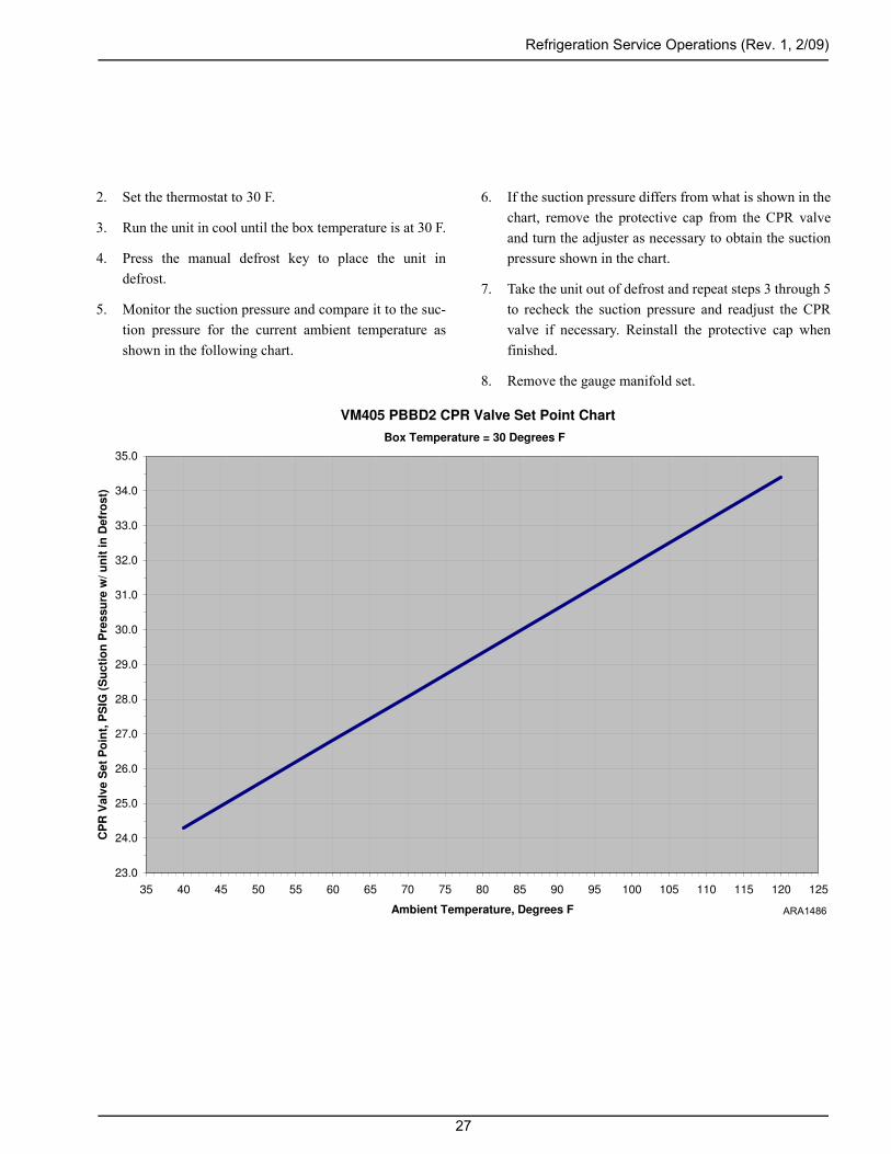
2. Set the thermostat to 30 F.
3. Run the unit in cool until the box temperature is at 30 F.
4. Press the manual defrost key to place the unit indefrost.
5. Monitor the suction pressure and compare it to the suc-tion pressure for the current ambient temperature asshown in the following chart.
6. If the suction pressure differs from what is shown in thechart, remove the protective cap from the CPR valveand turn the adjuster as necessary to obtain the suctionpressure shown in the chart.
7. Take the unit out of defrost and repeat steps 3 through 5to recheck the suction pressure and readjust the CPRvalve if necessary. Reinstall the protective cap whenfinished.
8. Remove the gauge manifold set.
VM405 PBBD2 CPR Valve Set Point Chart
23.0
24.0
25.0
26.0
27.0
28.0
29.0
30.0
31.0
32.0
33.0
34.0
35.0
35 40 45 50 55 60 65 70 75 80 85 90 95 100 105 110 115 120 125
Ambient Temperature, Degrees F
CP
R V
alv
e S
et
Po
int,
PS
IG (
Su
cti
on
Pre
ssu
re w
/ u
nit
in
Defr
ost)
Box Temperature = 30 Degrees F
ARA1486
27

28

Structural Maintenance
UNIT INSPECTION
Inspect the unit during the pre-trip inspection and duringscheduled maintenance inspections for loose or brokenwires or hardware, compressor oil leaks, or other physicaldamage which might affect the unit performance andrequire the repair or replacement of parts.
EVAPORATOR COIL
Clean the evaporator coil during scheduled maintenanceinspection by blowing compressed air through the coil inthe direction opposite the normal air flow. Inspect the coiland fins for damage and repair if necessary.
CAUTION: Air pressure should not be high enoughto damage the coil fins.
CONDENSER COIL
Clean the condenser coil during scheduled maintenanceinspections by blowing compressed air from the back sideof the coil out toward the front of the unit (the directionopposite normal air flow). Inspect the coil and fins for dam-age and repair if necessary.
UNIT MOUNTING BOLTS
Periodically check and torque the unit mounting bolts.
29

30

Mechanical Diagnosis
If the desired box temperature cannot be obtained, any ofthe following may be indicated:
EXCESSIVE HEAT LOAD. An excessive heat load onthe system will be caused by too many, or excessively long,door openings. Excessive heat loads will also be caused byloose doors, loose body panels, warm loads and poor insula-tion.
DIRT ON COILS. Dirt on the condenser or evaporatorcoils acts as an insulator reducing the capacity of the unit.
SHORTAGE OF REFRIGERANT. Shortage of refriger-ant reduces the capacity of the unit. Find and remedy thecause of the shortage and recharge the system. DO NOToperate the unit if there is an indication of low charge. DONOT operate below 30 F (-1 C) box temperature if therefrigerant is foaming in the sight glass on the liquid line.
EXCESSIVE OIL. Too much compressor oil in the systemmay result in lower than normal suction pressure as well aslowered capacity.
MOISTURE IN THE SYSTEM. Symptom: Expansionvalve freeze-up—will not refrigerate. Usually this can bechecked by warming the expansion valve with either a handor hot towels to see if the valve opens. Evacuate the systemin the same manner used during installation. Install a newdrier.
EXPANSION VALVE LOSES ITS CHARGE. If theexpansion valve loses its charge, the valve will close caus-ing the system to go into vacuum. Replace the valve.
AIR IN THE SYSTEM. Air is not condensable. Its pres-ence in the system increases head pressure. When the com-pressor is stopped, air will gather at the high point of thehigh side. Recover and evacuate the system.
TEMPERATURE OF THE LIQUID LINE. During nor-mal operation, the liquid line will be slightly warmer thanthe surrounding air. An extremely hot line indicates either ashortage of refrigerant or a lack of a liquid seal at thereceiver outlet. A cold line indicates a restriction, and someflashing takes place in the liquid line sight glass.
DIRTY OR WET DRIER. If the outlet line of the drier iscolder than the inlet line, the drier is either saturated withmoisture or is dirty and must be replaced.
DIRT IN THE EXPANSION VALVE SCREEN. Recoverthe refrigerant charge, remove the screen and clean. If themoisture is in the refrigeration system, it will collect at theexpansion valve and freeze. This is indicated by abnormallylow suction pressure. Clean the system, replace the drier,evacuate the system pressurize and check for leaks. If noleaks are found, charge the system.
ICE ON THE EVAPORATOR COIL. Run the unitthrough a defrost cycle to remove the ice.
COMPRESSOR LIFE. Operating without sufficient oil inthe system, or at low temperatures over the road at highcompressor speeds, can cause short compressor life.
AIR FLOW. Do not load product directly in front of the airreturn or discharge. Ensure that the fan is correctly posi-tioned in the orifice to achieve maximum air flow.
31

32

Electrical Mechanical Diagnosis
CONDITION POSSIBLE CAUSE REMEDYCompressor does not run Improperly wired Check wiring against diagram
Low line voltage Check line voltage—determine location of voltage drop
Relay contacts not closing Check and replace relay if defective
Open circuit in motor winding Check motor leads. If leads OK, replace motor
Power relay open Check relay, replace if defective
Compressor wiring defective Close power supply start or disconnect switch
Fuses blown Replace fuses
Thermostat stuck open Refer to M13 troubleshooting
High pressure cutout switch open Eliminate cause of excessive pressure
Compressor piston stuck Replace compressor
Low pressure cutout open Recharge, leak test
Shortage of refrigerant Check for leaks, repair as required, and recharge
Overload relay open Turn On-Off switch OFF and back ON
Unit short cycles Shortage of refrigerant (low pressure cutout)
Repair leak and recharge
Evaporator fan rotating in wrong direction
Check DC motor polarity
Restricted expansion valve (low pressure cutout)
Replace expansion valve
Refrigerant overcharge (high pressure cutout)
Remove excess charge
Cycling on high pressure cutout Check air flow and fan
Clogged condenser coil Clean coil
33

Electrical Mechanical Diagnosis (Rev. 1, 2/09)
Unit operates long or continuously
Shortage of refrigerant Repair leak and recharge
Discharge valve leaking Replace compressor
Dirty condenser Clean condenser
Air in system Evacuate the system
Compressor inefficient Replace compressor
Plugged expansion valve Clean or replace
Iced or plugged coil Defrost or clean
Defective truck body insulation Correct or replace
Too many door openings Keep doors closed
Load too warm Precool hot product
Excessive superheat at expansion valve
Replace expansion valve
Door seals worn Repair/replace
Box temperature too high Refrigerant shortage Repair leak and recharge
Thermostat set too high Reset control
Expansion valve or strainer plugged Clean or replace
Restricted lines Clean restriction. Tubing pinched shut
Hot load Precool hot product
Expansion valve superheat too high or too low
Replace expansion valve
Head pressure too high Refrigerant overcharge Remove excess
Air in system Evacuate system
Dirty condenser Clean
Restricted condenser Clean condenser
Condenser fan not running Check fan motor
Condenser fan rotating backwards Check fan motor polarity
CONDITION POSSIBLE CAUSE REMEDY
34

Electrical Mechanical Diagnosis (Rev. 1, 2/09)
Head pressure too low Refrigerant shortage Repair leak and recharge
Compressor suction or discharge valve inefficient
Replace compressor
Noisy unit Insufficient compressor oil Add oil to proper level
Mounting bolts loose Tighten
Refrigerant flooding back Adjust oil level or refrigerant charge. Check expansion valve for proper superheat
Compressor loses oil Shortage of refrigerant Repair leak and recharge
Plugged expansion valve or strainer Clean or replace
Wrong oil viscosity Use proper oil
Short cycling Refer to Unit Short Cycles
Superheat too high Replace expansion valve
Frosted or sweating suction line Expansion valve set too low, admitting excess refrigerant
Frosted evaporator coil
Dirty evaporator coil
Evaporator fans fail
Replace expansion valve
Defrost coil
Clean or remove debris
Repair fans
Hot liquid line Shortage of refrigerant Repair leak and recharge
Frosted liquid line Restricted dehydrator or strainer Replace restricted part
Condenser coils cool when unit is in cool
Refrigerant undercharge Repair leak and recharge
Compressor inefficient Replace compressor
Unit in vacuum. Frost on expansion valve only
Ice plugging expansion valve orifice Apply hot wet cloth to expansion valve. Moisture indicated by increase in suction pressure. Replace drier
Plugged expansion valve strainer Clean strainer
Sensor bulb lost charge Replace expansion valve
CONDITION POSSIBLE CAUSE REMEDY
35

36

Refrigeration Diagnosis
Rapid
cyc
ling
Uni
t coo
ls in
def
rost
cyc
leH
igh
head
pre
ssur
eLo
w h
ead
pres
sure
No
head
pre
ssur
eH
igh
suct
ion
pres
sure
Low
suc
tion
pres
sure
No
suct
ion
pres
sure
Uni
t ope
ratin
g in
a v
acuu
mS
ight
gla
ss e
mpt
yS
uctio
n lin
e fro
stin
g ba
ckN
oisy
com
pres
sor
Uni
t not
refri
gera
ting
Uni
t not
def
rost
ing
SYM
PTO
M
POSSIBLE CAUSES• • • • Overcharge of refrigerant
• • • • • • Shortage of refrigerant
• • • • • No refrigerant
• Air through condenser too hot (ambient)
• Air flow through condenser restricted
• • • Air through condenser too cold (ambient)
• • • Air in refrigerant system
• Condenser fan blades bent or broken
• Air short cycling around evaporator coil
• • Air through evaporator restricted
• • • • Evaporator needs defrosting
• Compressor discharge valves leaking
• Compressor suction valves leaking
• Too much compressor oil in system
• Compressor bearing loose or burned out
• • Broken valve plate in compressor
• • Expansion valve power element lost its charge
• • Expansion valve feeler bulb improperly mounted
• • • Expansion valve feeler bulb making poor contact
37

Refrigeration Diagnosis (Rev. 1, 2/09)
• • Expansion valve open too much
• • Expansion valve closed too much
• • Expansion valve needle eroded or leaking
• • • Expansion valve partially closed by ice, dirt or wax
• • Liquid refrigerant entering compressor
• • Restricted line on the low side
• • • • Restricted line on the high side
• • • Restricted dehydrator
• • Reverse fan rotation
• • • Faulty pilot solenoid
• • Loose or broken electrical connections
• Condenser fan motor not operating
• • • • • Evaporator fan motor not operating
Rap
id c
yclin
gU
nit c
ools
in d
efro
st c
ycle
Hig
h he
ad p
ress
ure
Low
hea
d pr
essu
reN
o he
ad p
ress
ure
Hig
h su
ctio
n pr
essu
reLo
w s
uctio
n pr
essu
reN
o su
ctio
n pr
essu
reU
nit o
pera
ting
in a
vac
uum
Sig
ht g
lass
em
pty
Suc
tion
line
frost
ing
back
Noi
sy c
ompr
esso
rU
nit n
ot re
frige
ratin
gU
nit n
ot d
efro
stin
g
SYM
PTO
MPOSSIBLE CAUSES
38

Wiring Diagrams and Schematic Index
Dwg No. Drawing Title Rev. Page
1E21449 Schematic Diagram C 41
1E21448 Wiring Diagram C 42
1E21507 Refrigeration Diagram A 43
39

40

41
Schematic Diagram

42
Wiring Diagram

43
Refrigeration Diagram


![VMware ESXi 5.1 Reference - vmgu.ru · # vmware-cmd /vmfs/volumes///.vmx resume [soft | hard ] Get ESXi Host Platform Information (vCLI only)](https://static.fdocuments.net/doc/165x107/5af665cc7f8b9a9e598f524f/vmware-esxi-51-reference-vmguru-vmware-cmd-vmfsvolumesvolume-namevmvmvmx.jpg)