
51360Q Soda Blast Retrofit Kit - Eastwood
7
Soda Blast Retrofit Kit ™ Part #51360 U.S. Patent Pending
Transcript of 51360Q Soda Blast Retrofit Kit - Eastwood

Soda Blast Retrofi t Kit™
Part #51360
U.S. Patent Pending

2 © Copyright 2007 Easthill Group, Inc. Printed in the United States of America
Before You BeginIMPORTANT NOTE:This unit is supplied with abrasive blasting apparatus installed. A conversion with included Soda Blasting Components is required before blasting with Soda can be done. The blaster will not work with Soda without the Soda Blasting Components Installed!This Conversion should only be performed by those with a good work-ing knowledge of pneumatic fi ttings. Failure to properly seal or over tightening the NPT fi ttings can lead to component failure which could result in sudden air pressure release and cause serious injury.
PLEASE OBSERVE THE FOLLOWING SAFETY PRECAUTIONS:• Always wear full eye, hearing, skin and respiratory protection when
operating the Soda Blasting Retrofi t Kit. Dust may irritate or damage eyes and respiratory system, noise emissions may damage hearing and abrasive material ejected at high pressure can cause injury.
Required safety equipment includes:• A NIOSH N95 or equivalent approved dust mask.• Safety goggles or blasting hood.• Hearing protection.• Canvas, heavy rubber or leather abrasive blasting long gloves.
IMPORTANT NOTE: Although the Bicarbonate of Soda blasting media itself is safe in most situations, appropriate care should be taken when using or disposing as some removed paints and coatings may contain some levels of hazard-ous materials such as lead, zinc chromate, etc. Additional protection may be required in the presence of these substances.
• Read, fully understand and refer to the main Instruction Manual supplied with your Abrasive Blasting Unit fully before beginning this conversion and operation.
• Keep people, pets and valuable property away from nozzle dis-charge to avoid injury or unwanted damage.
• Be sure to release all pressure and drain remaining media from Abrasive Blaster if present, before beginning conversion process. The media will fl ow from the threaded hole on the underside of the tank when the existing fi tting assembly is removed.
IncludedIncludedPartsParts
U.S. Patent Pending
EastwoodPressure Blaster
Air Inlet Valve
Throttling Valve
Flow Hose(red)
Purge Hose(clear)
Blast Hose(black)
Media Flow Valve
Purge Valve
To order parts and supplies, call 1-800-345-1178 or visit www.eastwood.com 3

4 For technical assistance e-mail: [email protected]
Disassembly For Conversion1. Disconnect air supply to unit and release tank pressure if any.2. Loosen hose clamp and remove Flow Air Hose by pulling hose free
from barbed fi tting on the Abrasive Outlet Manifold. Note: Clarke and some other units have a swivel connection at the top end of hose for ease of disassembly and a threaded 45° connection at the Abrasive Outlet Manifold.
3. Remove Blast Nozzle Hose from Abrasive Outlet Manifold by remov-ing hose clamp and pulling hose free from barbed fi tting.
4. Loosen and remove the Abrasive Outlet Manifold and Ball Valve assembly from bottom of tank. (Fig 1). Note: Some tanks including ALC brand units have a 3⁄4” MNPT x 1⁄2” FNPT reducer fi tting at the tank bottom. Leave this in place.
5. Remove all shreds of thread sealing tape and inspect fi ttings and threads for cracks or damage.
Figure 1Figure 1
Remove Remove abrasive abrasive outlet outlet manifoldmanifold
Remove Remove shards of shards of sealing tapesealing tape
To order parts and supplies, call 1-800-345-1178 or visit www.eastwood.com 5
Assembly For Conversion1. Remove protective plastic cap from male threads on top of Soda
Blast Conversion Assembly.2. Using thread sealing tape, thread the assembly into the bottom of
the tank and tighten with a suitable wrench. Note: barbed fi tting & Clear Purge Hose should face forward (Fig.2). Note: Failure to prop-erly seal or over tightening fi ttings can lead to component failure which could result in sudden air pressure release and cause serious injury.
3. Place the Flow Air Hose over the rear-facing Barbed Fitting and tight-en existing hose clamp. Note: On some Clarke units; the Flow Air Hose is directly threaded into the Abrasive Outlet Manifold on a 45° angle. A 3/8” FNPT x 3/8” MNPT 45° fi tting is included for this appli-cation and if so equipped; remove the rear-facing Barbed Fitting and using thread sealing tape, replace it with the above 45° fi tting.
4. Place the Black Blast Nozzle Hose over the forward facing Barbed Fitting and tighten existing hose clamp.
Your blaster is now completely retrofi tted and ready to be fi lled with Soda Blasting Media.
Figure 2Figure 2
Eastwood Soda Eastwood Soda Blaster Retrofi t Kit™ Blaster Retrofi t Kit™ InstalledInstalled
US Patents Pending
45° fi tting shown

To order parts and supplies, call 1-800-345-1178 or visit www.eastwood.com 76 For technical assistance e-mail: [email protected]
IMPORTANT NOTE:Soda Blasting Media is highly susceptible to moisture absorption which will cause clumping and erratic operation. To insure proper function, it is imperative to have an effective moisture fi lter and or desiccant sys-tem in the air supply immediately before the Air Inlet. Be sure to drain any moisture captured in the moisture fi lter before and after each use. Failure to do so may cause “caking” of media and complete blockage of equipment.
Operation1. Refer to the specifi c safety and operation information in the instruc-
tion manual included with your Pressure Blaster before continuing.2. Carefully fi ll the unit per Blaster Instructions using a screen sifter and
funnel. Note: a suitable screen sifter such as an Eastwood #22022 must be used to capture any clumps present in the bag of media.
3. Close all four valves and connect the air supply. DO NOT EXCEED 125 PSI. For best results, begin with a blaster inlet pressure of 80 to 90 PSI. To avoid media clumping or caking, be certain to have a clean, moisture free air supply that includes an effective moisture fi lter or desiccant system.
4. Open the Inlet Air Supply Valve slowly while checking for leakage.5. Slowly open the Throttling Valve (Fig. 3) to the 1⁄2 position while
checking for leakage. Note: This valve will require fi ne tuning to pro-vide optimal media fl ow based on media formulation, air pressure and desired volume.
6. Slowly open the Media Flow Valve to the full position while checking for leakage.
7. You may now direct the nozzle toward your work and depress the Nozzle Discharge Lever. Note: Some slow, pulsing discharges of media can be expected until the fl ow begins.
8. Once a steady fl ow of media is observed, begin by holding the nozzle 6” to 12” from the work surface at a 30° to 45° angle for best results.
9. Hold the stream against the work until it abrades through the coat-ing revealing an edge.
10. Use the stream as a “wedge” working at the edge to quickly remove the coating.
11. At this point you can vary the position of the Throttling Valve (Fig. 3) from the initial 1⁄2 open starting setting to achieve an optimum air/media ratio. Note: As there are many variables affecting the fl ow such as media formulation, hardness of coating, air volume, air pressure and atmospheric conditions, this process requires a bit of “trial and error” by experimenting with distance, angle and throttle position. You will quickly become profi cient at determining the ideal settings.
12. When refi lling the tank becomes necessary, fi rst shut off the Inlet Air Supply Valve, The Throttle Valve and The Flow Valve. For safety, disconnect the air supply. Next, open the Inlet Air Supply Valve to release all tank pressure. You may then open the Tank Filler Cap and refi ll per fi lling instructions in your users manual.
13. It is strongly advisable to drain all unused media when completing work as any moisture present in the tank will drain to the bottom of the tank and can create a solid “cake” with the media, requiring complete disassembly of the apparatus at the bottom of the tank.
14. To drain unused media from the tank, place the open end of The Clear Purge Hose into a suitable vessel such as a large bucket or box with closed seams and cover with a blanket. Using extreme care, slowly open the Purge Valve and direct the stream of media into the vessel.
Figure 3Figure 3
Air Inlet ValveAir Inlet Valve
Throttle Valve Throttle Valve (shown in halfway position)(shown in halfway position)
8 For technical assistance e-mail: [email protected]
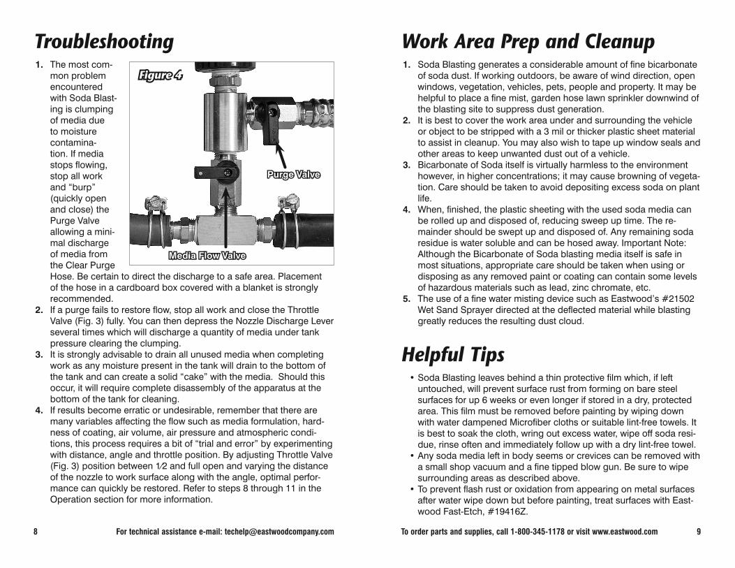
Troubleshooting1. The most com-
mon problem encountered with Soda Blast-ing is clumping of media due to moisture contamina-tion. If media stops fl owing, stop all work and “burp” (quickly open and close) the Purge Valve allowing a mini-mal discharge of media from the Clear Purge Hose. Be certain to direct the discharge to a safe area. Placement of the hose in a cardboard box covered with a blanket is strongly recommended.
2. If a purge fails to restore fl ow, stop all work and close the Throttle Valve (Fig. 3) fully. You can then depress the Nozzle Discharge Lever several times which will discharge a quantity of media under tank pressure clearing the clumping.
3. It is strongly advisable to drain all unused media when completing work as any moisture present in the tank will drain to the bottom of the tank and can create a solid “cake” with the media. Should this occur, it will require complete disassembly of the apparatus at the bottom of the tank for cleaning.
4. If results become erratic or undesirable, remember that there are many variables affecting the fl ow such as media formulation, hard-ness of coating, air volume, air pressure and atmospheric condi-tions, this process requires a bit of “trial and error” by experimenting with distance, angle and throttle position. By adjusting Throttle Valve (Fig. 3) position between 1⁄2 and full open and varying the distance of the nozzle to work surface along with the angle, optimal perfor-mance can quickly be restored. Refer to steps 8 through 11 in the Operation section for more information.
Purge ValvePurge Valve
Media Flow ValveMedia Flow Valve
Figure 4Figure 4
To order parts and supplies, call 1-800-345-1178 or visit www.eastwood.com 9
Work Area Prep and Cleanup1. Soda Blasting generates a considerable amount of fi ne bicarbonate
of soda dust. If working outdoors, be aware of wind direction, open windows, vegetation, vehicles, pets, people and property. It may be helpful to place a fi ne mist, garden hose lawn sprinkler downwind of the blasting site to suppress dust generation.
2. It is best to cover the work area under and surrounding the vehicle or object to be stripped with a 3 mil or thicker plastic sheet material to assist in cleanup. You may also wish to tape up window seals and other areas to keep unwanted dust out of a vehicle.
3. Bicarbonate of Soda itself is virtually harmless to the environment however, in higher concentrations; it may cause browning of vegeta-tion. Care should be taken to avoid depositing excess soda on plant life.
4. When, fi nished, the plastic sheeting with the used soda media can be rolled up and disposed of, reducing sweep up time. The re-mainder should be swept up and disposed of. Any remaining soda residue is water soluble and can be hosed away. Important Note: Although the Bicarbonate of Soda blasting media itself is safe in most situations, appropriate care should be taken when using or disposing as any removed paint or coating can contain some levels of hazardous materials such as lead, zinc chromate, etc.
5. The use of a fi ne water misting device such as Eastwood’s #21502 Wet Sand Sprayer directed at the defl ected material while blasting greatly reduces the resulting dust cloud.
Helpful Tips• Soda Blasting leaves behind a thin protective fi lm which, if left
untouched, will prevent surface rust from forming on bare steel surfaces for up 6 weeks or even longer if stored in a dry, protected area. This fi lm must be removed before painting by wiping down with water dampened Microfi ber cloths or suitable lint-free towels. It is best to soak the cloth, wring out excess water, wipe off soda resi-due, rinse often and immediately follow up with a dry lint-free towel.
• Any soda media left in body seems or crevices can be removed with a small shop vacuum and a fi ne tipped blow gun. Be sure to wipe surrounding areas as described above.
• To prevent fl ash rust or oxidation from appearing on metal surfaces after water wipe down but before painting, treat surfaces with East-wood Fast-Etch, #19416Z.

10 For technical assistance e-mail: [email protected]
Replacement Items• Soda Blast Media, Maintenance Formula, 50lb Bag #11806 (Smaller
crystal) • Soda Blast Media, Maintenance-XL Formula, 50lb Bag #11807
(Larger crystal)
Suggested Items• Soda Blasting Protection Kit, #50097 (Includes Dust Mask, Gloves,
Head Sock and Face Shield). Important Note: This Kit is suitable for soda dust protection. Additional protection may be required against hazardous materials present in coatings being removed such as lead, zinc chromate, etc.
• Eastwood Blast Media Screen Sifter #22022.• Considerable noise is generated during the blasting process. Suit-
able earphones or other hearing protection is strongly recommend-ed.
• Microfi ber Cloths (3 pack), #52210. High quality lint free cloths great for wiping down stripped surfaces prior to painting.
• Eastwood Fast-Etch Surface Rust Remover and Metal Prep, #19416Z.
• Access to a garden hose and water supply.• Eastwood’s #21502 Wet Sand Sprayer. Attach to work surface in
area being blasted to assist in dust containment. • Tefl on® thread sealing tape available at any home or automotive
supply store. • A roll or several packages of 3 mil or thicker plastic sheet material
for used media containment, vegetation protection and vehicle dust sealing.
To order parts and supplies, call 1-800-345-1178 or visit www.eastwood.com 11
Air Supply and Media ConsumptionIMPORTANT NOTE: This data is approximate and is presented for comparison use. This data is highly conservative and due to the many variables such as; com-pressor capacity, air line size, grade of media used, coating thickness and hardness, individual results will vary.
Nozzle Size
CFM @ 80 PSI
Approximate Media Usage
Area
3/32” 7 45 lbs/hr 200 sq. in./hr
1/8” 15 70 lbs/hr 325 sq. in./hr
5/32” 25 100 lbs/hr 390 sq. in./hr
3/16” 40 160 lbs/hr 440 sq. in./hr
1/4” 80 320 lbs/hr 560 sq. in./hr
5/16” 125 650 lbs/hr 900 sq. in./hr
Nozzle Size
CFM @ 80 PSI
Approximate Media Usage
Area
2mm 6 25 lbs/hr 135 sq. in./hr
2.5mm 12 35 lbs/hr 180 sq. in./hr
3mm 20 60 lbs/hr 250 sq. in./hr
3.5mm 25 75 lbs/hr 425 sq. in./hr
5mm 65 95 lbs/hr 1500 sq. in./hr

0 607174 006168
If you have any questions about the use of this product, please contactThe Eastwood Technical Assistance Service Department:
1-866-759-2131 email: [email protected]
The Eastwood Company263 Shoemaker Road, Pottstown, PA 19464, USA
US and Canada: 1-800-345-1178 Outside US: 610-718-8335fax: 610-323-6268 www.eastwood.com
Instruction Manual #51360Q - Rev. 11/09
Notes