510 Term Project - Portada | Alacero
35
Highway and Bridge Safety Barrier E. Shakirin, A. Omidvar 510 Term Project.docx page 1 of 35 CIVL 510 TERM PROJECT HIGHWAY AND BRIDGE SAFETY BARRIER EDRIS SHAKIRIN AND AMIR OMIDVAR UNIVERSITY OF BIRITISH COLUMBIA DEPARTMENT OF CIVIL ENGINEERING
Transcript of 510 Term Project - Portada | Alacero

Highway and Bridge Safety Barrier E. Shakirin, A. Omidvar
510 Term Project.docx page 1 of 35
CIVL 510
TERM PROJECT H I G H W AY A N D B R I D G E S A F E T Y B A R R I E R
EDRIS SHAKIRIN AND AMIR OMIDVAR
U N I V E R S I T Y O F B I R I T I S H C O L U M B I A D E P A R T M E N T O F C I V I L E N G I N E E R I N G

Highway and Bridge Safety Barrier E. Shakirin, A. Omidvar
510 Term Project.docx page 2 of 35
This report has been prepared by Edris Shakirin and Amir Omidvar
on instructive behalf of Prof. Dr. Stiemer
Published on 26 March 2010, Vancouver

Highway and Bridge Safety Barrier E. Shakirin, A. Omidvar
510 Term Project.docx page 3 of 35
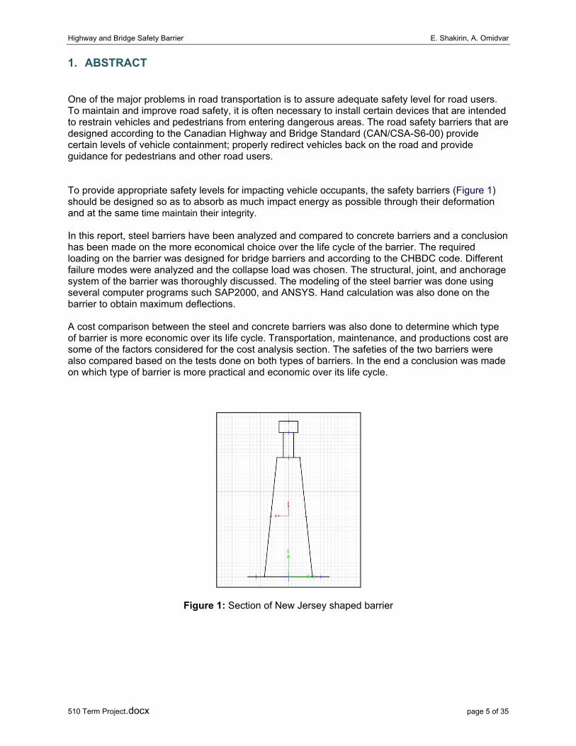
Contents 1. ABSTRACT .............................................................................................................................................. 5
2. INTRODUCTION ..................................................................................................................................... 6
3. METHODOLOGE .................................................................................................................................... 7
3.1. Safety on Highways and Bridges ................................................................................... 7
3.2. Crash test ...................................................................................................................... 8
3.3. Experimental Testing .................................................................................................... 9
4. LITERATURE RESEARCH OF BARRIER ................................................................................................... 10
4.1. General ........................................................................................................................ 10
4.2. Internet ....................................................................................................................... 10
5. STEEL BARRIERS REVIEW ..................................................................................................................... 11
5.1. General ........................................................................................................................ 11
5.2. Conventional Steel Barrier .......................................................................................... 11
5.3. Modern Steel Barrier .................................................................................................. 11
5.3.1. Permanent Barrier ...................................................................................................... 11
5.3.2. Temporary Barrier ....................................................................................................... 12
5.3.3. Available Products ....................................................................................................... 12
6. STEEL BARRIER DESIGN ....................................................................................................................... 13
6.1. Design Concept ........................................................................................................... 13
6.2. Designed Barrier .......................................................................................................... 14
7. STEEL BARRIER ANALYSIS .................................................................................................................... 15
7.1. Performance Level and Barrier Loadings .................................................................... 15
7.2. Failure Modes ............................................................................................................. 17
7.3. Analysis Model ............................................................................................................ 18
7.3.1. Hand Calculations........................................................................................................ 18
7.3.2. Computer Modeling ‐ SAP2000 ................................................................................... 19
7.3.3. Computer Modeling ‐ ANSYS ...................................................................................... 21
8. BARRIER CAPACITY .............................................................................................................................. 23
8.1. Structural System ........................................................................................................ 23
8.2. Joints ........................................................................................................................... 23
8.2.1. Force transfer of Bearing Type Bolts ........................................................................... 23
8.2.2. Shear Strength Design of Bearing Type Bolts .............................................................. 24
8.3. Anchorages .................................................................................................................. 26
Highway and Bridge Safety Barrier E. Shakirin, A. Omidvar
510 Term Project.docx page 4 of 35
9. STEEL AND CONCRETE BARRIER .......................................................................................................... 27
9.1. Safety Case .................................................................................................................. 27
9.2. Economic case ............................................................................................................. 27
9.2.1. Production ................................................................................................................... 27
9.2.2. Transportation ............................................................................................................ 27
9.2.3. Construction ................................................................................................................ 28
9.2.4. Maintenance ............................................................................................................... 28
9.2.5. Life Cycle Cost Model .................................................................................................. 28
9.3. Environmental case ..................................................................................................... 29
9.3.1. Air and Noise Pollution ............................................................................................... 29
10. CONCLUSIONS AND RECOMMENDATIONS ..................................................................................... 30
10.1. Design and Analysis summary ..................................................................................... 30
10.2. Further work ............................................................................................................... 30
REFERENCES ................................................................................................................................................ 31
APPENDICES ................................................................................................................................................ 32
APPENDIX A Crash test (NCHRP 350) ............................................................................................... 32
APPENDIX B Hand Calculation ......................................................................................................... 35
Highway and Bridge Safety Barrier E. Shakirin, A. Omidvar
510 Term Project.docx page 5 of 35
1. ABSTRACT
One of the major problems in road transportation is to assure adequate safety level for road users. To maintain and improve road safety, it is often necessary to install certain devices that are intended to restrain vehicles and pedestrians from entering dangerous areas. The road safety barriers that are designed according to the Canadian Highway and Bridge Standard (CAN/CSA-S6-00) provide certain levels of vehicle containment; properly redirect vehicles back on the road and provide guidance for pedestrians and other road users.
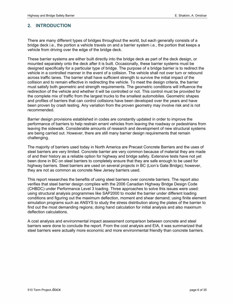
To provide appropriate safety levels for impacting vehicle occupants, the safety barriers (Figure 1) should be designed so as to absorb as much impact energy as possible through their deformation and at the same time maintain their integrity.
In this report, steel barriers have been analyzed and compared to concrete barriers and a conclusion has been made on the more economical choice over the life cycle of the barrier. The required loading on the barrier was designed for bridge barriers and according to the CHBDC code. Different failure modes were analyzed and the collapse load was chosen. The structural, joint, and anchorage system of the barrier was thoroughly discussed. The modeling of the steel barrier was done using several computer programs such SAP2000, and ANSYS. Hand calculation was also done on the barrier to obtain maximum deflections.
A cost comparison between the steel and concrete barriers was also done to determine which type of barrier is more economic over its life cycle. Transportation, maintenance, and productions cost are some of the factors considered for the cost analysis section. The safeties of the two barriers were also compared based on the tests done on both types of barriers. In the end a conclusion was made on which type of barrier is more practical and economic over its life cycle.
Figure 1: Section of New Jersey shaped barrier
Highway and Bridge Safety Barrier E. Shakirin, A. Omidvar
510 Term Project.docx page 6 of 35
2. INTRODUCTION
There are many different types of bridges throughout the world, but each generally consists of a bridge deck i.e., the portion a vehicle travels on and a barrier system i.e., the portion that keeps a vehicle from driving over the edge of the bridge deck.
These barrier systems are either built directly into the bridge deck as part of the deck design, or mounted separately onto the deck after it is built. Occasionally, these barrier systems must be designed specifically for a particular type of bridge. The purpose of a bridge barrier is to redirect the vehicle in a controlled manner in the event of a collision. The vehicle shall not over turn or rebound across traffic lanes. The barrier shall have sufficient strength to survive the initial impact of the collision and to remain effective in redirecting the vehicle. To meet the design criteria, the barrier must satisfy both geometric and strength requirements. The geometric conditions will influence the redirection of the vehicle and whether it will be controlled or not. This control must be provided for the complete mix of traffic from the largest trucks to the smallest automobiles. Geometric shapes and profiles of barriers that can control collisions have been developed over the years and have been proven by crash testing. Any variation from the proven geometry may involve risk and is not recommended.
Barrier design provisions established in codes are constantly updated in order to improve the performance of barriers to help restrain errant vehicles from leaving the roadway or pedestrians from leaving the sidewalk. Considerable amounts of research and development of new structural systems are being carried out. However, there are still many barrier design requirements that remain challenging.
The majority of barriers used today in North America are Precast Concrete Barriers and the uses of steel barriers are very limited. Concrete barrier are very common because of material they are made of and their history as a reliable option for highway and bridge safety. Extensive tests have not yet been done in BC on steel barriers to completely ensure that they are safe enough to be used for highway barriers. Steel barriers are used on several projects in BC (Lion’s Gate Bridge); however, they are not as common as concrete New Jersey barriers used.
This report researches the benefits of using steel barriers over concrete barriers. The report also verifies that steel barrier design complies with the 2006 Canadian Highway Bridge Design Code (CHBDC) under Performance Level 3 loading. Three approaches to solve this issues were used: using structural analysis programmes like SAP2000 to model the barrier under different loading conditions and figuring out the maximum deflection, moment and shear demand; using finite element simulation programs such as ANSYS to study the stress distribution along the plates of the barrier to find out the most demanding regions; doing hand calculation for initial analysis and also maximum deflection calculations.
A cost analysis and environmental impact assessment comparison between concrete and steel barriers were done to conclude the report. From the cost analysis and EIA, it was summarized that steel barriers were actually more economic and more environmental friendly than concrete barriers.
Highway and Bridge Safety Barrier E. Shakirin, A. Omidvar
510 Term Project.docx page 7 of 35
3. METHODOLOGE
3.1. Safety on Highways and Bridges
Roadside safety addresses an area outside of the roadway and is an important component of the total roadway design. Road design in the future will increasingly focus on the safety of all users. Upgrading existing roads to with higher safety standard coupled with greater drivers’ awareness will lead to significant savings in crash costs on roads. To achieve safer roads one has to consider three key areas:
• Safer people: Encourage safe behaviour by continuous education of drivers and public. • Safer vehicles: Continuing improvements in vehicle safety. • Safer roads: Build and maintain better and safer roads, improve safety barriers.
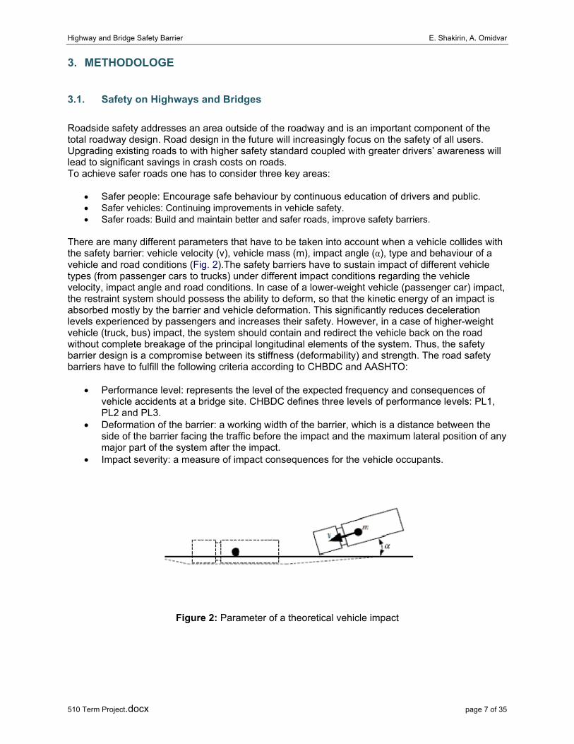
There are many different parameters that have to be taken into account when a vehicle collides with the safety barrier: vehicle velocity (v), vehicle mass (m), impact angle (α), type and behaviour of a vehicle and road conditions (Fig. 2).The safety barriers have to sustain impact of different vehicle types (from passenger cars to trucks) under different impact conditions regarding the vehicle velocity, impact angle and road conditions. In case of a lower-weight vehicle (passenger car) impact, the restraint system should possess the ability to deform, so that the kinetic energy of an impact is absorbed mostly by the barrier and vehicle deformation. This significantly reduces deceleration levels experienced by passengers and increases their safety. However, in a case of higher-weight vehicle (truck, bus) impact, the system should contain and redirect the vehicle back on the road without complete breakage of the principal longitudinal elements of the system. Thus, the safety barrier design is a compromise between its stiffness (deformability) and strength. The road safety barriers have to fulfill the following criteria according to CHBDC and AASHTO:
• Performance level: represents the level of the expected frequency and consequences of vehicle accidents at a bridge site. CHBDC defines three levels of performance levels: PL1, PL2 and PL3.
• Deformation of the barrier: a working width of the barrier, which is a distance between the side of the barrier facing the traffic before the impact and the maximum lateral position of any major part of the system after the impact.
• Impact severity: a measure of impact consequences for the vehicle occupants.
Figure 2: Parameter of a theoretical vehicle impact

Highway and Bridge Safety Barrier E. Shakirin, A. Omidvar
510 Term Project.docx page 8 of 35
Procedures for the Theoretical Head Impact Velocity (THIV), Post-Impact Head Deceleration (PHD), and the Acceleration Severity Index (ASI); and Figure 3 contains the level for evaluating of impact effects. These levels are well accepted by European and North American Countries.
Figure 3: Impact Severity Levels
The ASI value indicates the severity of the forces acting on the vehicle occupants during collision. For the value below 1.0, is the risk of injury to occupants is very low and for highway barriers the value shouldn’t be higher than 1.4. The theoretical impact velocity of the head is regarded as a measure of the impact severity of the vehicle on the restraint system. The head PHD delay after impact is then expressed in multiples of g (gravity).
3.2. Crash test
The road safety barriers installed on highways in Canada need to fulfil the Canadian Highway Bridge Design Code (CHBDC) CAN/CSA-S6-00 standard prepared by the Canadian Standards Association (CSA). The CHBDC standard prescribes criteria which the safety barrier has to fulfill under specific impact conditions.
Barrier have to be installed on Canadian Highways, a bridge barrier system must be successfully crash tested according CHBDC based on National Cooperative Highway Research Program Report 350 (NCHRP 350). Depending on the expected usage of the bridge, there are various test levels that determine the specific crash tests to be performed. According to the NCHRP350 criteria, PL3 longitudinal barriers under Test Level 4 (TL4) must be subjected to three full-scale vehicle crash tests (Appendix A2):
• A 820-kg small car impacting at a speed of 100 km/h and at an angle of 20° • A 2,000-kg pickup truck impacting at a speed of 100 km/h and at an angle of 25° • A 8,000-kg single-unit truck impacting at a speed of 80 km/h and at an angle of 15°
In addition, the AASHTO presents Manual for Assessing Safety Hardware (MASH), a uniform guideline for crash testing permanent and temporary highway safety features and recommends evaluation criteria to assess test results. MASH is an update to and supersedes NCHRP350.
Impact Severity Levels Values

Highway and Bridge Safety Barrier E. Shakirin, A. Omidvar
510 Term Project.docx page 9 of 35
Impact conditions as defined by the mass, speed, and angle of the impacting vehicle should bigger than Impact severity (IS) nominal values. For a longitudinal barrier, it is preferable that the actual IS be equal to or greater than the target value NCRHP 350-Table 3.6 (Appendix A).
IS=1/2M(V*Sin(α))2
Where IS is the impact severity in joules (J), M is the test inertial mass of the vehicle in kilograms (kg), V is the impact speed in meters/second (m/s), and 0 is the impact angle in degrees (degree). For our case the nominal Impact severity for a small car with two Passengers is 43.3 kJ,
IS= 43325 J or N.m
nominal Impact severity for a pickup truck with two Passengers is 147.5 kJ,
IS= 147460 J or N.m
and nominal Impact severity for a single-unit truck is 132.3 kJ.
IS=132320 J or N.m
For design of the Barrier we use impact energy of 43 kJ and 148 kJ. These energies will be dissipated respectively by plastic moments of barrier plate (based on Yield-line theory) and by plastic hinges of barrier element (based on Simple-beam system), failure mechanisms.
W External = W Internal
3.3. Experimental Testing
Experimental testing or static or dynamic analysis in the lab should be also considered as alternative to evaluate the barrier capacity. Dynamic effect of load impact on steel barrier is too small to consider it in design and analysis.
There are many tests performed on concrete road barriers. The Center for Transportation Research (CTR) at The University of Texas at Austin, performed the pendulum test and equivalent static test for the T203 and T501 barriers with mechanical anchors. They are also performed both crash test and static test with full-scale Jersey safety shaped barrier based on NCHRP 350 Test Level 4. It can be concluded:
• The static tests match well with crash tests (pendulum test). • The static tests provide an accurate ultimate capacity of barrier (slow loading, dynamic
effects are negligible). • A concrete barrier doesn’t achieve its maximum capacity by large displacements.
In addition the knowledge gained from static testing of the anchorage capacity of precast concrete bridge barrier by C. Ngan and Dr. S.F. Stiemer, Civil Engineering Department of UBC, confirm that results from static testing on barrier are advocated enough compared to crash test.

Highway and Bridge Safety Barrier E. Shakirin, A. Omidvar
510 Term Project.docx page 10 of 35
4. LITERATURE RESEARCH OF BARRIER
4.1. General
The literature review for this Project consist of considering applicable codes and standards for design and analysis of steel barrier, as well as comparison of common steel safety barriers with concrete barrier for highway.
• Review of CHBDC - CAN/CSA-S6-00, Canadian Highway Bridge Design Code. • Review of Supplement to CHBDC S6-06, BC Ministry of Transportation. • Review of AASHTO, LFRD Bridge Design Specification. • Review of NCHRP 350, crash test approach for barrier based on. • Literature review of conventional and modern steel barrier and barrier testing. • Review handbook of steel construction for design and analysis. • Review the dynamic effect of load impact on Barrier. • Literature review of anchorages type.
4.2. Internet
• Review of available product in United State and Europe. • Review of steel barrier usage survey and general attitude around the world. • Practise in other provinces and municipalities (Figure 4)
Figure 4: Traffic Control Devices; Alberta Transportation Standard Specification for Highway Construction, February 4, 2010)

Highway and Bridge Safety Barrier E. Shakirin, A. Omidvar
510 Term Project.docx page 11 of 35
5. STEEL BARRIERS REVIEW
5.1. General
A steel barrier system is intended to contain and/or redirect an impacting vehicle. Barrier systems are categorized on the basis of their design deflection characteristics:
• Flexible: Energy dissipation by deflection of the system, barrier elements act as a chain. Work zone on highways, because of high lateral deflection.
• Rigid: Energy dissipation by deflection of elements. Median or roadside on Bridges, because of low lateral deflection and light weight.
The design deflection is the distance that a barrier system is expected to move laterally under impact, measured from the face of the system. Rigid systems, as their name implies, do not deflect significantly. Flexible systems generally deflect 1.5 m or less. The design deflection of a barrier system is important, in that it determines the minimum separation between the barrier system and the hazard that is being protected. If the system is placed too close, the impacting vehicle may deflect the barrier system into the hazard, allowing the vehicle to strike the hazard, thereby defeating the purpose of the barrier system. Barrier systems, whether they are rigid or flexible, must be of sufficient length and be properly anchored to develop their full strength. For rigid systems, sufficient length and mass are necessary to prevent the system from being displaced upon impact. This study has adopted the performance requirements for steel barrier systems which are tested based on the NCHRP Report 350 ‐ Recommended Procedures for the Safety Performance Evaluation of Highway Features.
In addition, small vehicle and truck rollover accidents can be very costly, especially in urban areas and on bridges, because these accidents usually result in fatalities and injuries, vehicle and roadway damage, and traffic delays. Losses are even greater when trucks carrying combustible or hazardous cargo are involved. One way to prevent or at least reduce truck rollover accidents on curved routes or high performance highways and bridges would be the increasing of barrier’s height by installing of additional top steel railing on standard PL3 barrier. The CHBDC recommend increasing the height of barrier up to 1.37 m for high performance level.
5.2. Conventional Steel Barrier
Conventional steel barriers (or metal rails) such a as beam railing or W-beam post barrier are not sufficient to provide required safety, especially on high performance bridges and highways.
5.3. Modern Steel Barrier
5.3.1. Permanent Barrier
Permanent barriers are used in applications where it is desired that their deflection during vehicular impacts be limited. The permanent barriers can be installed as a median or side road on highway and bridges or during bridge construction. Temporary barriers placed close to the deck edge pose a major safety hazard to errant vehicles, as there is a significant risk for the barrier segments to be propelled off of the bridge. Thus, large dynamic deflections, in conjunction with the narrow gap behind the barriers may push the barriers off of the deck, along with the impacting vehicle. Therefore, a permanent steel barrier will be very suitable, particularly in design of bridge safety elements due light weight and sufficient strength.
Highway and Bridge Safety Barrier E. Shakirin, A. Omidvar
510 Term Project.docx page 12 of 35
5.3.2. Temporary Barrier
Construction or work zones are found along almost all provincial and local highways in the Canada. In most cases, these roadways often require the redirection of vehicular traffic around or through the construction zone. Typically, some form of temporary barrier is used to separate the flow of traffic within the construction area. In general, temporary barriers are segmented units that are attached end to end by a load-bearing connection. The segmentation of the barriers allows them to be easily installed, repositioned, and removed from the work-zone region. The barrier system is designed to protect equipment and workers in the work zone, to prevent errant vehicles from leaving the traveled way, and to safely redirect those vehicles impacting the barrier.
5.3.3. Available Products
Following products are recommended to use on Canadian highways and bridges. All this product are tested (TL4) according to NCHRP 350 or European EN 1317 and satisfy requirements of the CHDBC S6-06.
• Zone Guard; Springvale Business and Industrial Park • Barrier Guard 800; Barrier Systems Incorporated • Bridge Guard, with sliding plate system; Safe German Guardrail Technology (SGGT)

Highway and Bridge Safety Barrier E. Shakirin, A. Omidvar
510 Term Project.docx page 13 of 35
6. STEEL BARRIER DESIGN
6.1. Design Concept
Barrier systems should be designed with consideration for adjacent roadside features. The selection and design of a barrier system must include consideration of the roadway, shoulder, drainage facilities and the roadside environment of the surrounding area. Together, these elements are designed to maximizing the safety benefits of the highway as a system. Conversely, situations that reduce safety can develop when the interaction of roadside features (including barrier systems) is not given adequate consideration. The proper performance of barrier systems is heavily dependent on the correct design, installation, maintenance and post‐impact repair. Grading and anchorage requirements should also receive proper attention.
For tests examining performance of the length-of-need section, rails or barrier NCHRP 350 required that elements should be installed straight and level and anchored. As a general rule, length of the test section excluding terminals or end anchorage devices should be at least three times the length in which deformation is predicted but not less than 23 m for a rigid barrier. The rigid bridge Barrier length, strength, and geometry should be sufficient to approximate impact response expected of the in-service bridge rail. It is recommended that the length of the bridge barrier element be 5 m at a minimum. A minimum of 15 m of the more flexible barrier is recommended, exclusive of a properly anchored end. The above information from NCHRP 350 and Supplement to CHBDC (BSM Vol-1 Aug 2007) is used for the design of the steel bridge barrier (Figure 5).
Figure 5: Performance level PL-3, Cast-in-place concrete bridge parapet (1070 mm High), MOT/BC Supplement to CHBDC S6-06 Figure 12.4.6.1.d

Highway and Bridge Safety Barrier E. Shakirin, A. Omidvar
510 Term Project.docx page 14 of 35
6.2. Designed Barrier
In this study steel barrier designed to have failure mechanisms in following steps, failure of barrier plate, failure of barrier element and failure of anchors. The length of the barrier element is 6 m and the height equals 1.07 m. The barrier ends are longitudinally connected to each other by bolts and supported by stiffeners. The designed connection between two elements should provide enough strength to transfer part of impact loads to the next element. In addition failure mechanism of barrier element which suppose to happen after the plate failure. The New Jersey-shaped barrier is designed with dimensions of 6 m length; 1.07 m Barrier height and 1.37 m total height; 0.72 m base width and 0.20 m top width. All above dimension are recommended by CHBDC and there are selected and modified based on engineering judgments. The thickness of the barrier plate is 4 mm and preliminary calculated based on Yield-line theory. Figure 6 illustrate the designed barrier section is used in this analysis.
Base step of the barrier is designed to provide additional support for the barrier, since the weight of the car provides local support at the point of impact.The barriers are supported to ground by four anchors at a distance of 0.5 m from the barrier end. In addition the front and back steps are connected with a 20 mm width plate every 1 m. The numbers of anchors are selected four, because of construction and cost issues. This could be changed when further analysis is done or modification of the section barrier may require.
It should be mentioned to improve the barrier section strength, it is recommenced to use stiffener along the barrier section. The stiffeners improve section properties of barrier and allow barrier to act as a box. The barrier will have the properties like a hollow shaped section with increased the moment capacity and torsinal resistance.
Figure 6: Section and dimention of designed barrier
Highway and Bridge Safety Barrier E. Shakirin, A. Omidvar
510 Term Project.docx page 15 of 35
7. STEEL BARRIER ANALYSIS
7.1. Performance Level and Barrier Loadings
The primary purpose of a barrier system is to reduce the collision severity when the vehicle leaves the roadway and encounters hazards (fixed objects or terrain features) that are less forgiving than striking the barrier system. Traffic barrier requirements for bridges are based on the expected frequency and consequences of vehicle accidents at a bridge site. This procedure assumes the frequencies and consequences of vehicle accidents at bridge sites are a function of many variables, such as highway curvatures, grades, etc. The ranking system used in CHBDC to determine the site conditions of a bridge site is categorized into three levels:
• Performance Level 1 (PL-1): The performance level for traffic barriers on bridges where the expected frequency and consequences of vehicles leaving the roadway are similar to that expected on low traffic volume roads.
• Performance Level 2 (PL-2): The performance level for traffic barriers on bridges where the expected frequency and consequences of vehicles leaving the roadway are similar to that expected on high to moderate traffic volume highways.
• Performance Level 3 (PL-3): The performance level for traffic barriers on bridges where the expected frequency and consequences of vehicles leaving the roadway are similar to that expected on high traffic volume highways with high percentage of trucks.
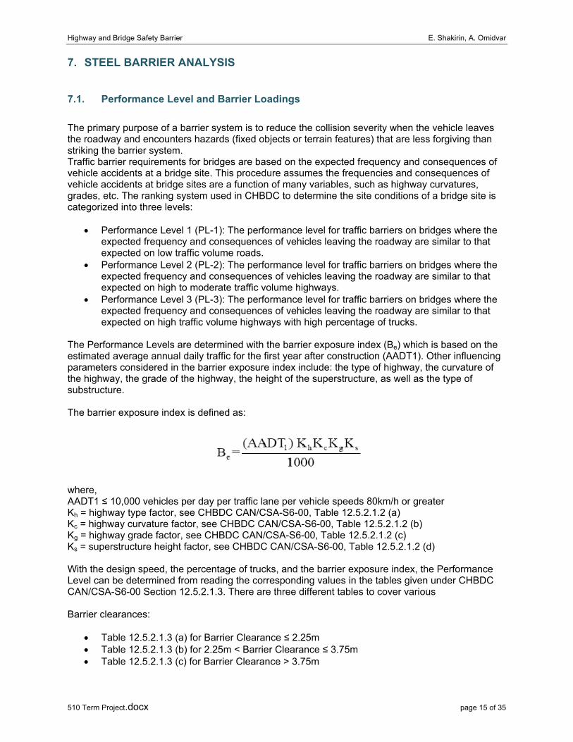
The Performance Levels are determined with the barrier exposure index (Be) which is based on the estimated average annual daily traffic for the first year after construction (AADT1). Other influencing parameters considered in the barrier exposure index include: the type of highway, the curvature of the highway, the grade of the highway, the height of the superstructure, as well as the type of substructure.
The barrier exposure index is defined as:
where, AADT1 ≤ 10,000 vehicles per day per traffic lane per vehicle speeds 80km/h or greater Kh = highway type factor, see CHBDC CAN/CSA-S6-00, Table 12.5.2.1.2 (a) Kc = highway curvature factor, see CHBDC CAN/CSA-S6-00, Table 12.5.2.1.2 (b) Kg = highway grade factor, see CHBDC CAN/CSA-S6-00, Table 12.5.2.1.2 (c) Ks = superstructure height factor, see CHBDC CAN/CSA-S6-00, Table 12.5.2.1.2 (d)
With the design speed, the percentage of trucks, and the barrier exposure index, the Performance Level can be determined from reading the corresponding values in the tables given under CHBDC CAN/CSA-S6-00 Section 12.5.2.1.3. There are three different tables to cover various
Barrier clearances:
• Table 12.5.2.1.3 (a) for Barrier Clearance ≤ 2.25m • Table 12.5.2.1.3 (b) for 2.25m < Barrier Clearance ≤ 3.75m • Table 12.5.2.1.3 (c) for Barrier Clearance > 3.75m

Highway and Bridge Safety Barrier E. Shakirin, A. Omidvar
510 Term Project.docx page 16 of 35
Based on the Performance Level, a minimum barrier height can be determined using Table 12.5.2.2. The minimum barrier heights for PL1, 2, and 3 traffic barriers are 0.68 m, 0.80 m, and 1.05 m respectively. Traffic barrier height requirements are intended to prevent impacting vehicles from vaulting or rolling over a barrier. The higher the center of gravity of the impacting vehicle, the greater the required traffic barrier height is needed to contain it. The geometry of the roadway face of a traffic barrier as well as the transition into the roadway face of the approach roadway traffic barrier shall have a smooth and continuous alignment, as laid out in Section 12.5.2.2 of CHBDC CAN/CSA-S6-00. Where a traffic barrier is located between the roadway and a sidewalk or bikeway, the sidewalk or bikeway face of the barrier should have a minimum height of 0.60 m measured from the surface of the sidewalk or bikeway.
Alternative Performance Levels, as mentioned in Section 12.5.2.1.1 in CHBDC CAN/CSA-S6-00, have to be approved by the Regularity Authority for the bridge and defined by specifying their crash test requirements. These levels shall be considered along with Performance Level 1, 2, or 3 when determining the optimum performance level. We have decided the to use PL-3 for our barrier design since we have designing our barrier for cases similar to Port Mann Bridge where they have used PL-3 for their designs.
We have complied with CHBDC code for our barrier design and analysis and according to the CHBDC code static analysis and testing of barrier is an economical and adequate method for realistic barrier capacity evaluation. A barrier satisfying Performance Level 3 needs to meet the specified loading requirements by CHBDC code. A summary of the loading requirements is shown at the table below:
Load Forces Height of Application Spread of Load
Transverse Load 240 kN 810 mm from base 1070 mm
Longitudinal Load 80 kN 810 mm from base 1070 mm
Vertical Load 90 kN Top of the barrier 5500 mm
Based on NCHRP 350-Appendix A13 all forces shall applied to the longitudinal rail elements. The distribution of longitudinal loads to posts shall be consistent with the continuity of rail elements. For TL4 test following loading length are specified: the length of 1070 mm for Lt and LL is the length of significant contact between the vehicle and railing that has been observed in films of crash tests. The length of 1070 mm for TL-4 is the rear-axle tire diameter of the truck (Figure 7 and Appendix A).
Figure 7: NCHRP350 Impact loads and length on barrier

Highway and Bridge Safety Barrier E. Shakirin, A. Omidvar
510 Term Project.docx page 17 of 35
7.2. Failure Modes
Several failure modes were analyzed for our barrier system under different loading conditions. The failure modes analyzed were obtained by implementation of the plastic analysis theory to our barrier. A review of plastic analysis theory is discussed below:
According to the CISC Handbook of Steel Construction, Clause 8.5, the forces and moments due to a loading combination on a structure may be determined by plastic analysis, provided that certain requirements are met:
• The steel used has fy ≤ 0.80*fu • The width to thickness ratio of the section conform to those of a Class 1 section as given in
Clause 11.2 • The members are braced laterally as required by Clause 13.7 • Web stiffeners are supplied at point load application locations • Slices are designed to transmit 1.1 times the maximum moment at the splice location, or
0.25*Mpl, whichever is greater • Members are not subjected to repeated load or fatigue • Inelastic deformation during collapse is taken into account.
In plastic analysis, a structure is assumed to be loaded until the plastic moment has been reached at enough locations in the system to produce a collapse mechanism or unstable system. The internal work in the system due to the deformed state during collapse is equal to the external work in the system.
The kinematic theorem states that “for a given frame structure subjected to a set of loads λP, the value of λ which corresponds to the assumed mechanism must be greater than or equal to the collapse load factor λc“(CIVL510 Lecture Notes).
For a structure, the number of possible independent collapse mechanisms is equal to the number of possible plastic hinge locations (where the plastic moment has been reached) minus the number of redundancies in the system. Possible plastic hinge locations include the location of the application of a concentrated load or the resultant of a distributed load, the location of a support, and the location of a change in geometry such as a corner of the structure.
By representing the loads on the structure as a function of λ and equating the internal and external work of the possible mechanisms, the mechanism which will produce the lowest λ can be identified. Since the λ associated with the collapse load must be less than or equal to the lowest λ found, and no other collapse mechanisms are possible, the lowest λ must be equal to λc, and the associated assumed mechanism will be the collapse mechanism. By following this procedure, the collapse mechanism and the collapse load of any structural system may be identified.
The steel barriers must be designed for the failure to happen in the following steps:
I. The failure of the plate under the impact load II. The failure of barrier element under impact load III. The failure of the connection between the plates and the anchorage system IV. The failure of the anchorage system which is best to be avoided. This failure is known to be
fatal since the car can fall out the road. In The failure steps above the car is still on the road.
By analyzing different loading conditions and checking the moment and shear demands, we can conclude that the there are two different loading conditions resulting in maximum deflection and maximum shear. If the transverse and longitudinal loads are applied at the middle of the two anchors, the barrier will experience maximum deflection, whereas, if the transverse and longitudinal loads are applied at the location of the connection, the barrier will experience maximum shear.

Highway and Bridge Safety Barrier E. Shakirin, A. Omidvar
510 Term Project.docx page 18 of 35
7.3. Analysis Model
All parts of the barrier system are made of the construction steel with yield strength of 350 Mpa. Material properties of analyzed barrier elements in terms of their Young’s modulus, yield stress, ultimate strength and corrosion protection requirements are according to CSA Standard CAN/CSA G40.20/G40.21 and G164. The plastic moment reduction due to axial force must be considered in the plastic analysis, especially when the axial force N exceeds 15% Npl. In this analysis, because of low effect of axial forces (Longitudinal Load) and complicity of calculation is not further considered.
Npl = fy*A = 350 kN*1070 mm *3mm = 1498 kN N = 80 kN N/Npl = 80/1498 = 5.3% ≤ 15%
Where, A is the front plate’s section area of barrier.
7.3.1. Hand Calculations
We also attempted to calculate the deformation, shear and flexural demands of the barrier using hand calculation. We used plastic analysis for our calculation, mainly using yield line theory for plates. We analyzed different modes of failure and performed the plastic analysis on each model. In our attempt to calculate the deflections of the plate we used the virtual work theory. We calculated the external work which was the impact severity of the collision:
IS = 1/2M(V*Sinα)2 [kJ]
The solution is obtained by equating the external work due to the applied loads to the internal work done by the resisting moments along the yield lines. It is based on the assumptions that:
Wext. = Wint.
Wext. = IS Wint. = ∑ (Mpl*θ*l)
• The yield line failure pattern occurs within the parapet only and does not extend into the deck • Sufficient longitudinal length of parapet exists to result in the yield line failure pattern • Negative and positive resisting moments in the barrier body are equal
Yield-line theory is used to calculate the thickness of barrier plate. As we mentioned in 6.2 the plate have to dissipate the energy of a small car and 43 kJ. Following approximate calculation is done:
Wint. = Mpl*38.72 kJ Wext. = 43 kJ Mpl = fy*Z = 1.11 kN.m/m Z = b*d2/4 d ~ 4 mm
In second step a simple beam model is used to approximately calculate the Plastic capacity of barrier element. The barrier has to dissipate the energy of a single unit truck and 148 kJ.
Wint. = Mpl*4*Δ/L kJ Δ=unity=1m Wint.= 284 kJ Wext. = 148 kJ Wext. ≤ Wint. Mpl = fy*Z = 1.11 kN.m/m Z = (200*43*10)+(1075*4*30)+(150*4*570/2)*2 = 608000 mm3

Highway and Bridge Safety Barrier E. Shakirin, A. Omidvar
510 Term Project.docx page 19 of 35
A Summary of hand calculation is included in appendix B of this report. However, in analysis of the shear and moment demand of the system the calculation became quite cumbersome and time consuming which lead us to use computer software and modeling for our shear and flexural demands.
7.3.2. Computer Modeling - SAP2000
To better understand the behaviour of the steel barrier under service loads, a computer model of the barrier was designed using SAP2000 program. SAP2000 is advanced analysis software, capable of using both static and dynamic analysis of the barrier. The code used by the SAP2000 program was the American code which is quite close to CSI code, the barrier was designed in the program according to the dimensions and the properties of steel were defined. The program determined the shear and moment demand on the anchors and bolts of the barrier as well as the maximum deflection according to the service loads.
We implemented three different models for our analysis of the barrier: the beam model, the pipe and plate model and the solids model.
The beam model of the barrier was done by simply assuming the barrier section to a beam with support in place of the bolts and anchors. The shape of the barrier was drawn in the section designer section of the program (Figure #) and the loads were applied to the beam at the specified locations.
Figure 8: A 3D view of the beam model is shown in figure below:

Highway and Bridge Safety Barrier E. Shakirin, A. Omidvar
510 Term Project.docx page 20 of 35
Figure 9: Beam model in SAP2000
This figure shows a 12 meter span of the barrier with the loads applied in the middle of the supports to result in maximum deflection. Other models were also formed for maximum shear and moment. The major problem with this model was the vertical location of the loads. According to our requirements, the transverse loads must be applied on the surface of the barrier at a height of 810 mm. In the beam model; however, the load is applied to the whole surface and a preferred height cannot be specified. This results in conservative numbers which are not accurate enough. The bending moment diagram, shear diagram and deflection curves were quite accurate and were used for further analysis.
In the pipe and plate model, the barrier was designed by designed separate plates and connecting them to each other by providing supports at the points of connection to ensure integrity of the whole system. A 3D view of the system is shown in figure below.
Figure 10: Pipe model in SAP2000

Highway and Bridge Safety Barrier E. Shakirin, A. Omidvar
510 Term Project.docx page 21 of 35
The blue section in the figure indicates the location of the applied forces (transverse and the longitudinal). Also the supports at the bottom represent the bolts and anchors whereas the supports at the top are positioned to connect the plates to each other making the system a whole. In the pipe and plate model the loads applied to the system were dealt with locally by the program which meant that only the plate where the load were applied deformed and the model did not work as a system. Therefore we moved on to our third and final model which was the solid prism model.
In the solid prism model, we designed our barriers as a prism block with the required dimensions and applied the supports at the specified locations. This model was the most promising model since both the system worked as a whole and also the vertical location of the loads could be specified. A SAP model of the beam is shown in the figure below:
Figure 11. Solid prism model in SAP2000
By using other features of SAP2000 program, we were able to draw the stress distribution along the plate due to different loading conditions to find out which regions were the most demanding regions in term of shear and flexural strength. Drawing the stress distribution also helped us find out if our designs were adequate under the PL3 loadings. A deflection diagram of the system was also depicted which showed how the plate deformed under different loading conditions. This was a good test to see if our model worked properly since we knew how our system would deform under the loading conditions. The only shortcoming of this model was assigning the property of material to the system. It was no possible to give the most accurate material property to this model since it was not hollow; therefore, we approximated the material property of the hollow section to the block section and the results were reasonable but not very accurate.
7.3.3. Computer Modeling - ANSYS
In our final attempt to calculate the deformation, shear and flexural demands of the barrier we used the ANSYS program for our analysis. This software is a general purpose finite element modeling package for numerically solving a wide variety of mechanical problems including static/dynamic structural analysis (both linear and non-linear). The three major modules of the program are pre-processing (geometry creation, meshing), solver, and post processing. The PCBB was modeled using SOLID95 elements. SOLID95 is a 3-D 20-Node structural solid having three degrees of freedom (DOF) per node. The software can consider plasticity, creep, stress stiffening, large deflection, and large strain capabilities and tolerate irregular shapes without as much loss of accuracy. An isometric view of our barrier is shown in the figure below:

Highway and Bridge Safety Barrier E. Shakirin, A. Omidvar
510 Term Project.docx page 22 of 35
Figure 12: Finite element model in ANSYS The numbers for deflection, shear and moment in the ANSYS model were quite reasonable and close the SAP2000 model. Therefore, we ended up using the results from the SAP2000 model.
Highway and Bridge Safety Barrier E. Shakirin, A. Omidvar
510 Term Project.docx page 23 of 35
8. BARRIER CAPACITY
8.1. Structural System
The structural system used in this barrier consisted of metal plates, bolted connections and anchorage system to the ground. Web stiffeners were considered to be used at first but later were omitted because the distance between the anchorage connections resulted in adequate torsional strength. The front and back plates were welded to each other by a top plate which was welded to both plates. The bottom of the plates was connected to each other by welding small rectangular steel plates(420mm x 200mm) at the points of connections. The connections were bolted connections to the anchorage systems which will be explained in later sections. The number and types of the bolts were designed to resist the shear demand of the system under maximum shear demand loading condition.
8.2. Joints
As mentioned above in the report, we have decided to use bolted connection joints in our design. High strength bolts, type A325 or A490 (CSI LFRD) are required in most structural applications, such as our system; they must be sufficiently tightened to achieve the minimum bolt tension values. Bolts may be loaded in tension, shear, or a combination of shear and tension. We have used bearing type bolted connections in our design.
8.2.1. Force transfer of Bearing Type Bolts
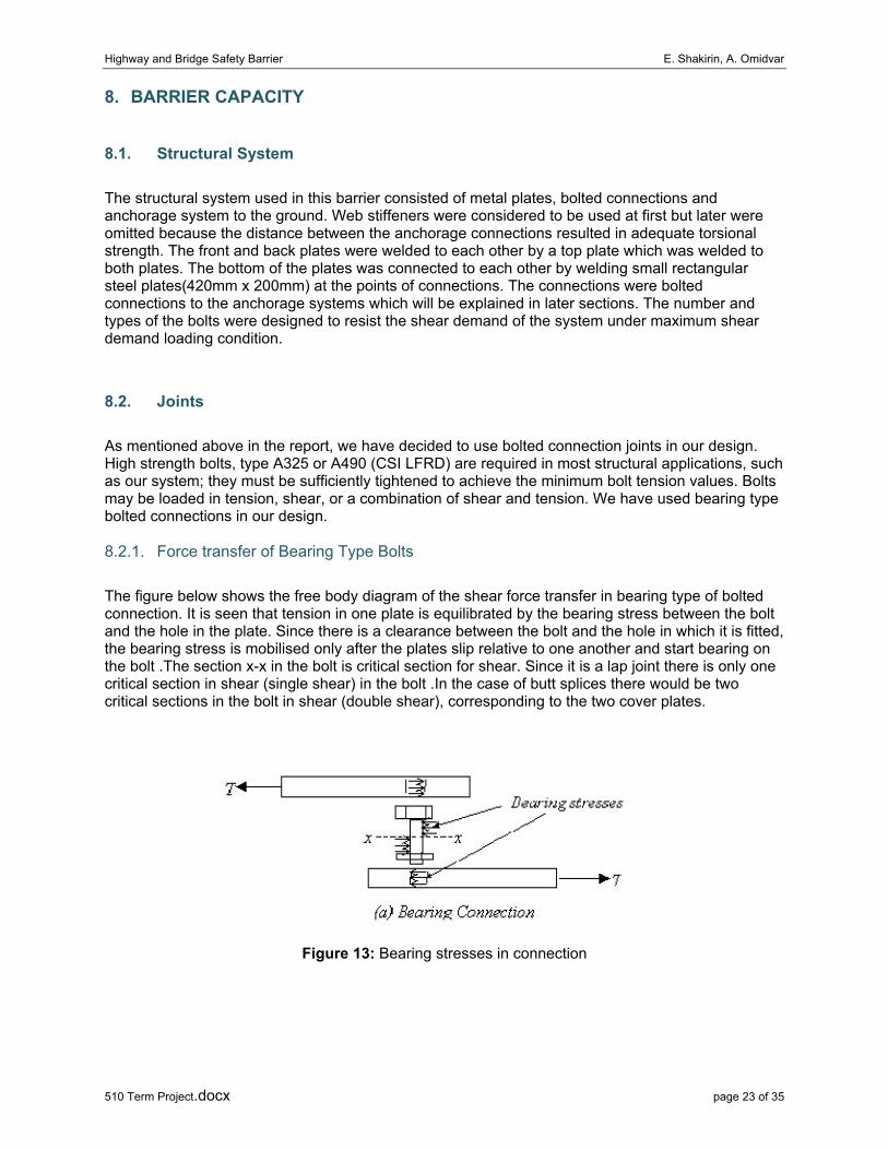
The figure below shows the free body diagram of the shear force transfer in bearing type of bolted connection. It is seen that tension in one plate is equilibrated by the bearing stress between the bolt and the hole in the plate. Since there is a clearance between the bolt and the hole in which it is fitted, the bearing stress is mobilised only after the plates slip relative to one another and start bearing on the bolt .The section x-x in the bolt is critical section for shear. Since it is a lap joint there is only one critical section in shear (single shear) in the bolt .In the case of butt splices there would be two critical sections in the bolt in shear (double shear), corresponding to the two cover plates.
Figure 13: Bearing stresses in connection
Highway and Bridge Safety Barrier E. Shakirin, A. Omidvar
510 Term Project.docx page 24 of 35
8.2.2. Shear Strength Design of Bearing Type Bolts
The failure of connections with bearing bolts in shear involves either bolt failure or the failure of the connected plates. In this section, the failure modes are described along with the code provisions for design and detailing shear connections.
In connections made with bearing type of bolts, the behavior is linear until
I. Yielding takes place at the net section of the plate under combined tension and flexure or II. Shearing takes place at the bolt shear plane or III. Failure of bolt takes place in bearing, IV. Failure of plate takes place in bearing and V. Block shear failure occurs.
Of these, I. and V. are discussed in the chapter on tension members. The remaining three are described below.
Shearing of bolts: The shearing of bolts can take place in the threaded portion of the bolt and so the area at the root of the threads, also called the tensile stress area At, is taken as the shear area As. Since threads can occur in the shear plane, the area Ae for resisting shear should normally be taken as the net tensile stress area, An, of the bolts. The shear area is specified in the code and is usually about 0.8 times the shank area. However, if it is ensured that the threads will not lie in the shear plane then the full area can be taken as the shear area.
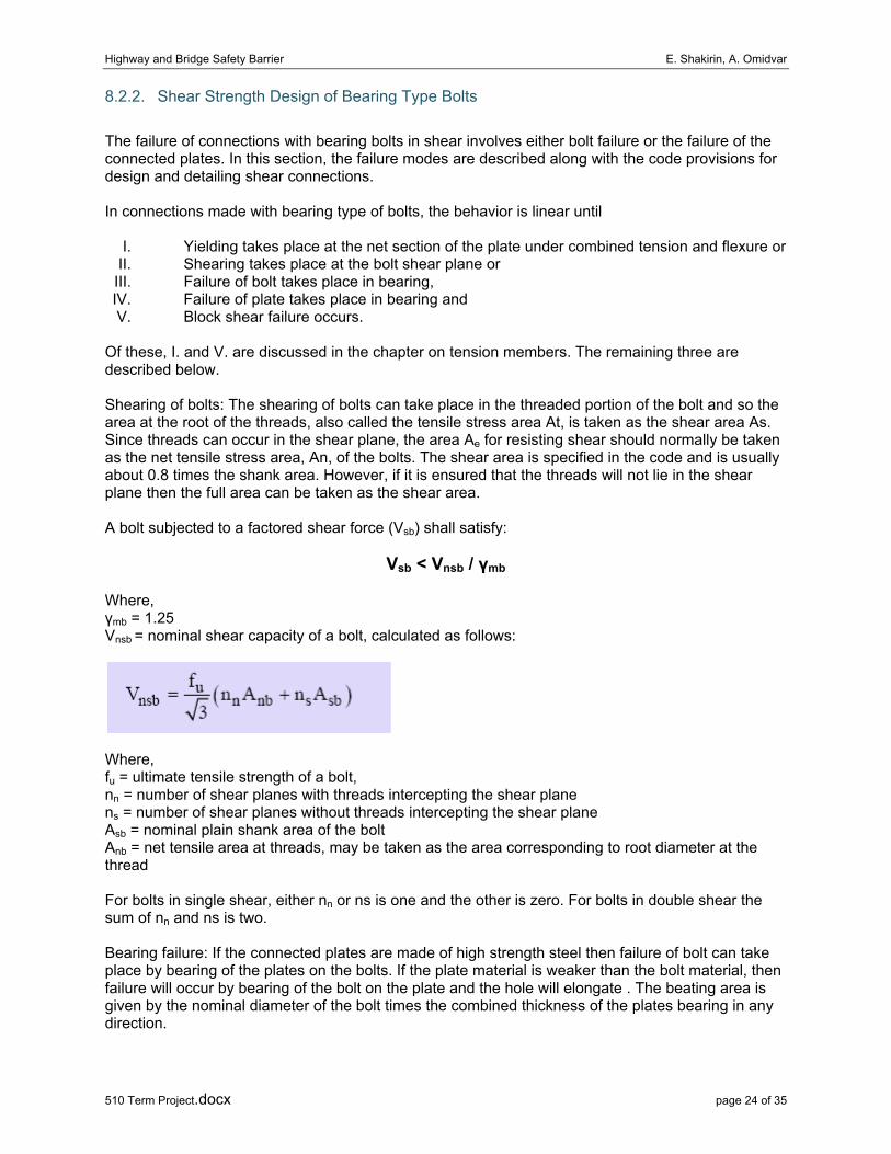
A bolt subjected to a factored shear force (Vsb) shall satisfy:
Vsb < Vnsb / γmb
Where, γmb = 1.25 Vnsb = nominal shear capacity of a bolt, calculated as follows:
Where, fu = ultimate tensile strength of a bolt, nn = number of shear planes with threads intercepting the shear plane ns = number of shear planes without threads intercepting the shear plane Asb = nominal plain shank area of the bolt Anb = net tensile area at threads, may be taken as the area corresponding to root diameter at the thread
For bolts in single shear, either nn or ns is one and the other is zero. For bolts in double shear the sum of nn and ns is two.
Bearing failure: If the connected plates are made of high strength steel then failure of bolt can take place by bearing of the plates on the bolts. If the plate material is weaker than the bolt material, then failure will occur by bearing of the bolt on the plate and the hole will elongate . The beating area is given by the nominal diameter of the bolt times the combined thickness of the plates bearing in any direction.

Highway and Bridge Safety Barrier E. Shakirin, A. Omidvar
510 Term Project.docx page 25 of 35
A bolt bearing on any plate subjected to a factored shear force (Vsb) shall satisfy:
Vsb < Vnpb / γmb
Where, γmb = 1.25 Vnpb = bearing strength of a bolt, calculated as Vnpb = 2.5*d*t*fu
and fu = smaller the ultimate tensile stress of the bolt and ultimate tensile stress of the plate d = nominal diameter of the bolt t = summation of the thicknesses of the connected plates experiencing bearing stress in the same direction.
Figure 14: Type of failures in a shear connection (a) Shearing of bolts (b) Bearing failure of plate (c) Bearing failure of bolt
The underlying assumption behind the design of bolted connections, namely that all bolts carry equal load is not true in some cases as mentioned below. In long joints, the bolts farther away from the centre of the joint will carry more load than the bolts located close to the centre. Therefore, for joints having more than two bolts on either side of the building connection with the distance between the first and the last bolt exceeding 15d in the direction of load, the nominal shear capacity Vns, shall be reduced by the factor, βlj, given by (Cl.10.3.2.1)
Where, d = nominal diameter of the bolt
Similarly, if the grip length exceeds five times the nominal diameter, the strength is reduced as specified in IS800. In multi-bolt connections, due to hole mismatch, all the bolts may not carry the same load. However, under ultimate load, due to high bearing ductility of the plates considerable redistribution of the load is possible and so the assumption that all bolts carry equal load may be considered valid.
Highway and Bridge Safety Barrier E. Shakirin, A. Omidvar
510 Term Project.docx page 26 of 35
8.3. Anchorages
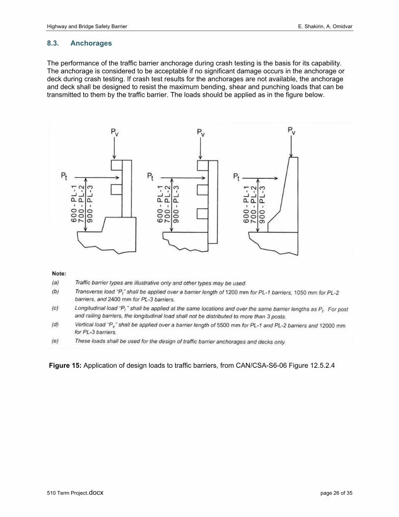
The performance of the traffic barrier anchorage during crash testing is the basis for its capability. The anchorage is considered to be acceptable if no significant damage occurs in the anchorage or deck during crash testing. If crash test results for the anchorages are not available, the anchorage and deck shall be designed to resist the maximum bending, shear and punching loads that can be transmitted to them by the traffic barrier. The loads should be applied as in the figure below.
Figure 15: Application of design loads to traffic barriers, from CAN/CSA-S6-06 Figure 12.5.2.4
Highway and Bridge Safety Barrier E. Shakirin, A. Omidvar
510 Term Project.docx page 27 of 35
9. STEEL AND CONCRETE BARRIER
9.1. Safety Case
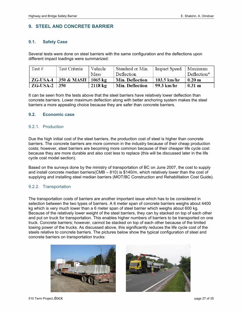
Several tests were done on steel barriers with the same configuration and the deflections upon different impact loadings were summarized:
It can be seen from the tests above that the steel barriers have relatively lower deflection than concrete barriers. Lower maximum deflection along with better anchoring system makes the steel barriers a more appealing choice because they are safer than concrete barriers.
9.2. Economic case
9.2.1. Production
Due the high initial cost of the steel barriers, the production cost of steel is higher than concrete barriers. The concrete barriers are more common in the industry because of their cheap production costs; however, steel barriers are becoming more common because of their cheaper life cycle cost because they are more durable and also cost less to replace (this will be discussed later in the life cycle cost model section).
Based on the surveys done by the ministry of transportation of BC on June 2007, the cost to supply and install concrete median barriers(CMB – 810) is $140/m, which relatively lower than the cost of supplying and installing steel median barriers (MOT/BC Construction and Rehabilitation Cost Guide).
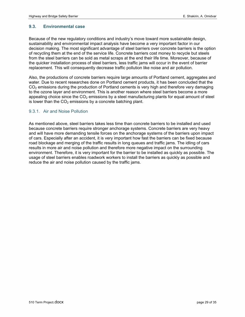
9.2.2. Transportation
The transportation costs of barriers are another important issue which has to be considered in selection between the two types of barriers. A 6 meter span of concrete barriers weighs about 4400 kg which is very much lower than a 6 meter span of steel barrier which weighs about 600 kg. Because of the relatively lower weight of the steel barriers, they can by stacked on top of each other and put on truck for transportation. This enables higher numbers of barriers to be transported on one truck. Concrete barriers; however, cannot be stacked on top of each other because of the limited towing power of the trucks. As discussed above, this significantly reduces the life cycle cost of the steels relative to concrete barriers. The pictures below show the typical configuration of steel and concrete barriers on transportation trucks:

Highway and Bridge Safety Barrier E. Shakirin, A. Omidvar
510 Term Project.docx page 28 of 35
9.2.3. Construction
Because of the weight of the concrete barriers, the anchorage system for the concrete barriers requires to be very strong to avoid anchorage failure of the barrier. Due to this issue, the construction and installation of concrete barriers take more time and costs more money relative to steel barriers. However, because of the large number of manufacturers of concrete barrier in North America, the construction cost of the barriers is very much cheaper than the steel barriers. Steel barriers are not very common in North America and there are not many manufacturing companies in North America to produce the barriers; therefore, the construction cost of the steel barriers is higher.
9.2.4. Maintenance
The maintenance cost of the barriers can be divided into two categories: the cost of Maintenance due to wear and tear and the cost of Maintenance after accidents. The Maintenance cost of the concrete barriers are lower due to the nature of the material; however, the installation time of the steel barriers after accidents are much lower which reduces the air and noise pollution which will be discussed later. The cost of Maintenance of the steel due to wear and tear is almost similar to concrete barriers over the life cycle of the barriers since the steel barriers are more durable, provided good corrosion protection, and therefore require less maintenance than concrete.
9.2.5. Life Cycle Cost Model
The following table compares the life cycle cost of the steel barriers and concrete barriers. It can be seen that the steel barriers cost less over their life time than concrete barriers.
Concrete Barriers Steel Barriers
Production Costs Cost less to produce Costs more than concrete due nature of the material
Installation Costs Cost more because takes more time
Cost less because of time saved on anchorage installation
Maintenance costs due to wear and tear Approximately equal to steel Approximately equal to concrete
Maintenance cost after accidents
Costs more because of more time
Costs less because of the reduction in pollution
Transportation costs Costs more because of higher mass
Costs less because it can be stacked on the truck
Recycling costs Need to pay at the end of life cycle to be recycled
Can be sold as metal scraps at the end of life cycle
Highway and Bridge Safety Barrier E. Shakirin, A. Omidvar
510 Term Project.docx page 29 of 35
9.3. Environmental case
Because of the new regulatory conditions and industry’s move toward more sustainable design, sustainability and environmental impact analysis have become a very important factor in our decision making. The most significant advantage of steel barriers over concrete barriers is the option of recycling them at the end of the service life. Concrete barriers cost money to recycle but steels from the steel barriers can be sold as metal scraps at the end their life time. Moreover, because of the quicker installation process of steel barriers, less traffic jams will occur in the event of barrier replacement. This will consequently decrease traffic pollution like noise and air pollution.
Also, the productions of concrete barriers require large amounts of Portland cement, aggregates and water. Due to recent researches done on Portland cement products, it has been concluded that the CO2 emissions during the production of Portland cements is very high and therefore very damaging to the ozone layer and environment. This is another reason where steel barriers become a more appealing choice since the CO2 emissions by a steel manufacturing plants for equal amount of steel is lower than the CO2 emissions by a concrete batching plant.
9.3.1. Air and Noise Pollution
As mentioned above, steel barriers takes less time than concrete barriers to be installed and used because concrete barriers require stronger anchorage systems. Concrete barriers are very heavy and will have more demanding tensile forces on the anchorage systems of the barriers upon impact of cars. Especially after an accident, it is very important how fast the barriers can be fixed because road blockage and merging of the traffic results in long queues and traffic jams. The idling of cars results in more air and noise pollution and therefore more negative impact on the surrounding environment. Therefore, it is very important for the barrier to be installed as quickly as possible. The usage of steel barriers enables roadwork workers to install the barriers as quickly as possible and reduce the air and noise pollution caused by the traffic jams.
Highway and Bridge Safety Barrier E. Shakirin, A. Omidvar
510 Term Project.docx page 30 of 35
10. CONCLUSIONS AND RECOMMENDATIONS
10.1. Design and Analysis summary
Analysis investigations were conducted in order to study the behavior and obtain the capacity of steel barriers currently used in Europe and some parts of North America. The steel barrier was designed in accordance with BC Ministry of Transportation’s standard. The loading specification for design was based on the Canadian Highway Bridge Design Code for Performance Level 3 Traffic Barrier. Then, a comparison between the steel barrier and Precast Concrete Barrier was done where economic and safeties were some of the factors. The major findings are as follows:
• The steel barriers under the similar loading conditions to concrete barriers results in lower deflections and better stress distribution. This results in safer barrier than concrete.
• The steel barriers are more flexible than concrete barrier and can be used around curves of highways and bridges. The flexibility of the steel barriers results in better constructability than concrete barriers.
• During the life cycle of the two barriers, we can conclude that the steel barrier is more economic
• The steel barrier designs comply with the CHBDC code. • The anchorage strength of the steel barrier does not require being as high as the concrete
barrier. • The steel barriers should be designed to result in the following failure steps: • The failure of the plate under the impact loading • The failure of the barrier element under the impact loading • The failure of the connection between the plate and the anchorage system • The failure of the anchorage system due to high tensile loadings • CHBDC code create highly conservative products • The design program can be easily modified to accommodate for other steel barrier types and
updates.
10.2. Further work
Finite element simulation, computer simulation techniques supported the analysis efforts. The code utilized in the computer modeling efforts is LS-DYNA. LS-DYNA is a general-purpose, explicit finite element code used to analyze the nonlinear dynamic response of three-dimensional inelastic structures. This code is capable of capturing the complex interactions that occur when a vehicle impacts a roadside safety structure. In recent years, LS-DYNA has been used extensively for crashworthiness simulations of automobiles and their components by automobile manufacturers and by researchers in the roadside safety community in the design and evaluation of roadside safety features.
Also ANSYS, which is another finite element simulation program, was used to predict the stress distribution along the plate for different loading conditions. This software is a general purpose finite element modeling package for numerically solving a wide variety of mechanical problems including static/dynamic structural analysis (both linear and non-linear). The three major modules of the program are pre-processing (geometry creation, meshing), solver, and post processing.
Highway and Bridge Safety Barrier E. Shakirin, A. Omidvar
510 Term Project.docx page 31 of 35
REFERENCES • Experimental Investigations of Anchorage Capacity of Precast Concrete Bridge Barrier for
Performance Level 2 by Caroline Lai and Yung Ngan, B.A.S.C., University of British Columbia, 2006
• Zone guard™, Standard and Minimum Deflection arrangements, NCHRP 350 Test Level 3 (TL-3) and TL-4, April 3, 2008
• Ministry of Transportation Construction and Rehabilitation Cost Guide, June 2007 • Alberta Infrastructure and Transportation Roadside Design Guide, November 2007 • Design of Steel Structures – Bolted Connections by Prof. S.R. Satish Kumar and Prof. A.R.
Santha Kumar • NCHRP Report 500 - INJURY RELATED BARRIER • CSI Steel Design Code S6-06 Code • Stiemer, S.F. CIVL 510 Behaviour of Steel Structures (Lecture Notes), The University of
British Columbia, 2003. • AASHTO (2005). LRFD Bridge Design Specifications, 3rd ed., American Association of State
Highway and Transportation Officials, Washington, DC. • CAN/CSA-S6-06. Canadian Highway Bridge Design Code (CHBDC) A National Standard of
Canada, November 2006, CSA International, Toronto, Ontario. • CAN/CSA-S6-06. Commentary to the Canadian Highway Bridge Design Code, November,
2006, CSA International, Toronto, Ontario. • Barker, R.M. and Puckett, J.A. Design of Highway Bridge: based on AASHTO LRFD Bridge
Design Specifications. New York: John Wiley& Sons Inc. 1997. • HOW SUSTAINABLE IS CONCRETE? - By Leslie Struble and Jonathan Godfrey, University
of Illinois at Urbana-Champaign, USA • BC Ministry of Transportation, Construction and Rehabilitation Cost Guide • Alberta Transportation Standard Specification for Highway Construction • 2006 STANDARD SPECIFICATIONS FOR HIGHWAY CONSTRUCTION, BC - MOT

Highway and Bridge Safety Barrier E. Shakirin, A. Omidvar
510 Term Project.docx page 32 of 35
APPENDICES
APPENDIX A Crash test (NCHRP 350)
Table A1: AASHTO LRFD Bridge Design Speciation (not include the two passenger weight).
Table A2: AASHTO LRFD Bridge Design Speciation

Highway and Bridge Safety Barrier E. Shakirin, A. Omidvar
510 Term Project.docx page 33 of 35

Highway and Bridge Safety Barrier E. Shakirin, A. Omidvar
510 Term Project.docx page 34 of 35

Highway and Bridge Safety Barrier E. Shakirin, A. Omidvar
510 Term Project.docx page 35 of 35
APPENDIX B Hand Calculation