50E47-843 TECHNICAL WIRING HELP - SupplyHouse.coms3.supplyhouse.com/product_files/White Rodgers -...
4
Terminal Wiring Cross Reference Original Control Replacement Control Honeywell Robertshaw Old White-Rodgers Terminal Function S89 / S890 Terminal HS780 Terminal 50E / F47 Terminal 50E47-843 Burner Ground Connection GND (BURNER) a TR (GND CLIP) b GND GND Transformer Secondary 24V (GND) a GND TR TR (unswitched leg) Main Valve Common VALVE (GND) a — c MV a (next to MV2 TR terminal) Transformer Secondary 24V a TH TH TH (switched leg) Main Valve Operator VALVE VALVE d MV d MV1 120 Vac Neutral Leg L2 120V NEUTRAL L2 — L2 e Power Supply 120 Vac Hot Leg L1 120V HOT L1 L f L1 120V HOT Power Supply Hot Surface Igniter Element HSI 120V IGN — HS2 Hot Surface Igniter Element HSI 120V IGN IGN g HSI Flame Sensor SEN h RS h FP i FP h a Remove quick-connect and replace with the included 1/4” quick-connect. b Use green adapter cable (provided) to connect terminal to chassis ground. c Do not use the MV2 terminal. MV2 and TR are interconnected in the appliance wiring. d Remove quick-connect and replace with the included 3/16” quick-connect. e Ground this terminal using green adapter cable if model being replaced does not have 120V neutral power supply connec- tion. f Use the red wire on the included adapter cable. g Use the blue wire on the included adapter cable. h On indirect sense models, remove jumper quick-connect from FP terminal, cut jumper wire at circuit board and discard. On direct sense models, jumper connected to FP terminal, see figure 4. i Remove jumper from FP terminal, cut jumper wire at circuit board and discard. M V 2 T R G N D T H M V 1 L 2 F P L 1 H S 1 THERMOSTAT OR CONTROLLER ALTERNATE LIMIT L1 (HOT) L2 LIMIT CONTROLLER FLAME PROBE RED ADAPTER BLUE HOT SURFACE IGNITER MV MV GAS VALVE BURNER GROUND H S 2 TRANSFORMER JUMPER (clip) M V 2 T R G N D T H L 2 F P THERMOSTAT OR CONTROLLER ALTERNATE LIMIT L1 (HOT) L2 LIMIT CONTROLLER MV MV GAS VALVE BURNER GROUND HOT SURFACE IGNITER H S 2 FLAME PROBE L 1 M V 1 H S 1 TRANSFORMER JUMPER (clip) Fig. 1 – Typical hookup for White-Rodgers replacement with indirect sense using flame probe Fig. 3 – Typical hookup for competitive replacement with indirect sense using flame probe Fig. 4 – Program Key installation/Jump- er for models with indirect sense clip jumper Program Keys M V 2 T R G N D T H L 2 F P THERMOSTAT OR CONTROLLER ALTERNATE LIMIT L1 (HOT) L2 LIMIT CONTROLLER MV MV GAS VALVE BURNER GROUND HOT SURFACE IGNITER H S 2 FLAME PROBE L 1 M V 1 H S 1 TRANSFORMER JUMPER Fig. 2 – Typical hookup for competitive replacement with direct flame sense through ignitor Jumper Select and insert the correct program key to match the application. TECHNICAL HELP 50E47-843 WIRING L2 must be grounded www.white-rodgers.com 204 TECHNICAL HELP
-
Upload
nguyenkhanh -
Category
Documents
-
view
221 -
download
1
Transcript of 50E47-843 TECHNICAL WIRING HELP - SupplyHouse.coms3.supplyhouse.com/product_files/White Rodgers -...
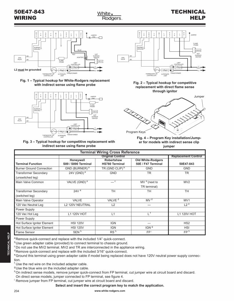
Terminal Wiring Cross Reference Original Control Replacement Control Honeywell Robertshaw Old White-Rodgers Terminal Function S89 / S890 Terminal HS780 Terminal 50E / F47 Terminal 50E47-843 Burner Ground Connection GND (BURNER) a TR (GND CLIP) b GND GND Transformer Secondary 24V (GND) a GND TR TR (unswitched leg) Main Valve Common VALVE (GND) a — c MV a (next to MV2 TR terminal) Transformer Secondary 24V a TH TH TH (switched leg) Main Valve Operator VALVE VALVE d MV d MV1 120VacNeutralLeg L2120VNEUTRAL L2 — L2e Power Supply 120 Vac Hot Leg L1 120V HOT L1 L f L1 120V HOT Power Supply HotSurfaceIgniterElement HSI120V IGN — HS2 Hot Surface Igniter Element HSI 120V IGN IGN g HSI Flame Sensor SEN h RS h FP i FP h
aRemovequick-connectandreplacewiththeincluded1/4”quick-connect. b Use green adapter cable (provided) to connect terminal to chassis ground. c Do not use the MV2 terminal. MV2 and TR are interconnected in the appliance wiring. dRemovequick-connectandreplacewiththeincluded3/16”quick-connect. e Ground this terminal using green adapter cable if model being replaced does not have 120V neutral power supply connec-tion. f Use the red wire on the included adapter cable. g Use the blue wire on the included adapter cable. hOnindirectsensemodels,removejumperquick-connectfromFPterminal,cutjumperwireatcircuitboardanddiscard. Ondirectsensemodels,jumperconnectedtoFPterminal,seefigure4. iRemovejumperfromFPterminal,cutjumperwireatcircuitboardanddiscard.
MV2
TR
GND
TH
MV1
L2
FP
L1
HS1
THERMOSTAT ORCONTROLLER
ALTERNATE LIMIT
L1(HOT)
L2
LIMITCONTROLLER
FLAME PROBE
RED
ADAPTER
BLUE
HOTSURFACEIGNITER
MV
MVGAS
VALVE
BURNERGROUND
HS2
TRANSFORMER
JUMPER(clip)
MV2
TR
GND
TH
L2
FP
THERMOSTAT ORCONTROLLER
ALTERNATE LIMIT
L1(HOT)
L2
LIMITCONTROLLER
MV
MVGAS
VALVE
BURNERGROUND
HOTSURFACEIGNITER
HS2
FLAME PROBE
L1
MV1
HS1
TRANSFORMER
JUMPER(clip)
Fig. 1 – Typical hookup for White-Rodgers replacement with indirect sense using flame probe
Fig. 3 – Typical hookup for competitive replacement with indirect sense using flame probe
Fig. 4 – Program Key installation/Jump-er for models with indirect sense clip
jumper
Program Keys
MV2
TR
GND
TH
L2
FP
THERMOSTAT ORCONTROLLER
ALTERNATE LIMIT
L1(HOT)
L2
LIMITCONTROLLER
MV
MVGAS
VALVE
BURNERGROUND
HOTSURFACEIGNITER
HS2
FLAME PROBE
L1
MV1
HS1
TRANSFORMER
JUMPER
Fig. 2 – Typical hookup for competitive replacement with direct flame sense
through ignitorJumper
Select and insert the correct program key to match the application.
TECHNICALHELP
50E47-843WIRING
L2 must be grounded
www.white-rodgers.com204
TEC
HN
ICA
L H
ELP
TECHNICALHELP
50E47-843 OPERATION& TROUBLESHOOTING
MV2
TR
GND
TH
MV1
L2
FP
L1
HS1
THERMOSTAT ORCONTROLLER
ALTERNATE LIMIT
L1(HOT)
L2
LIMITCONTROLLER
FLAME PROBE
RED
ADAPTER
BLUE
HOTSURFACEIGNITER
MV
MVGAS
VALVE
BURNERGROUND
HS2
TRANSFORMER
JUMPER(clip)
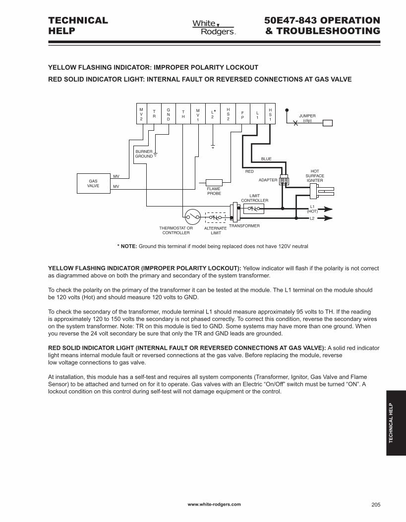
YELLOW FLASHING INDICATOR: IMPROPER POLARITY LOCKOUT
RED SOLID INDICATOR LIGHT: INTERNAL FAULT OR REVERSED CONNECTIONS AT GAS VALVE
YELLOW FLASHING INDICATOR (IMPROPER POLARITY LOCKOUT): Yellowindicatorwillflashifthepolarityisnotcorrectas diagrammed above on both the primary and secondary of the system transformer.
Tocheckthepolarityontheprimaryofthetransformeritcanbetestedatthemodule.TheL1terminalonthemoduleshouldbe 120 volts (Hot) and should measure 120 volts to GND.
Tocheckthesecondaryofthetransformer,moduleterminalL1shouldmeasureapproximately95voltstoTH.Ifthereadingis approximately 120 to 150 volts the secondary is not phased correctly. To correct this condition, reverse the secondary wires on the system transformer. Note: TR on this module is tied to GND. Some systems may have more than one ground. When you reverse the 24 volt secondary be sure that only the TR and GND leads are grounded.
RED SOLID INDICATOR LIGHT (INTERNAL FAULT OR REVERSED CONNECTIONS AT GAS VALVE): A solid red indicator light means internal module fault or reversed connections at the gas valve. Before replacing the module, reverse low voltage connections to gas valve.
Atinstallation,thismodulehasaself-testandrequiresallsystemcomponents(Transformer,Ignitor,GasValveandFlameSensor) to be attached and turned on for it to operate. Gas valves with an Electric “On/Off” switch must be turned “ON”. A lockoutconditiononthiscontrolduringself-testwillnotdamageequipmentorthecontrol.
* NOTE: Ground this terminal if model being replaced does not have 120V neutral
*
TEC
HN
ICA
L H
ELP
www.white-rodgers.com 205
TECHNICALHELP
50E47-843 OPERATION& TROUBLESHOOTING
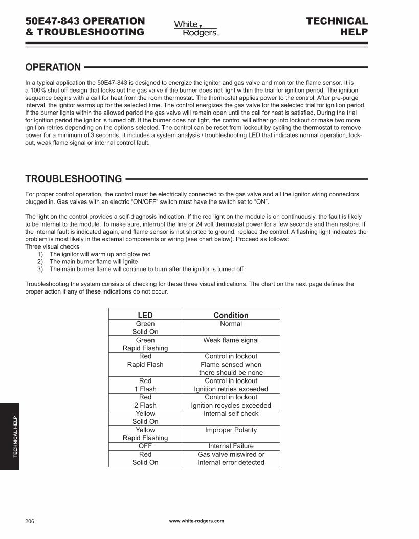
OPERATIONInatypicalapplicationthe50E47-843isdesignedtoenergizetheignitorandgasvalveandmonitortheflamesensor.Itisa100%shutoffdesignthatlocksoutthegasvalveiftheburnerdoesnotlightwithinthetrialforignitionperiod.Theignitionsequencebeginswithacallforheatfromtheroomthermostat.Thethermostatappliespowertothecontrol.Afterpre-purgeinterval, the ignitor warms up for the selected time. The control energizes the gas valve for the selected trial for ignition period. Iftheburnerlightswithintheallowedperiodthegasvalvewillremainopenuntilthecallforheatissatisfied.Duringthetrialforignitionperiodtheignitoristurnedoff.Iftheburnerdoesnotlight,thecontrolwilleithergointolockoutormaketwomoreignitionretriesdependingontheoptionsselected.Thecontrolcanberesetfromlockoutbycyclingthethermostattoremovepowerforaminimumof3seconds.Itincludesasystemanalysis/troubleshootingLEDthatindicatesnormaloperation,lock-out,weakflamesignalorinternalcontrolfault.
TROUBLESHOOTINGFor proper control operation, the control must be electrically connected to the gas valve and all the ignitor wiring connectors plugged in. Gas valves with an electric “ON/OFF” switch must have the switch set to “ON”.
Thelightonthecontrolprovidesaself-diagnosisindication.Iftheredlightonthemoduleisoncontinuously,thefaultislikelytobeinternaltothemodule.Tomakesure,interruptthelineor24voltthermostatpowerforafewsecondsandthenrestore.Iftheinternalfaultisindicatedagain,andflamesensorisnotshortedtoground,replacethecontrol.Aflashinglightindicatestheproblemismostlikelyintheexternalcomponentsorwiring(seechartbelow).Proceedasfollows:Threevisualchecks
1) The ignitor will warm up and glow red2) Themainburnerflamewillignite3) Themainburnerflamewillcontinuetoburnaftertheignitoristurnedoff
Troubleshootingthesystemconsistsofcheckingforthesethreevisualindications.Thechartonthenextpagedefinestheproper action if any of these indications do not occur.
LED Condition Green Normal Solid On Green Weakflamesignal Rapid Flashing Red Controlinlockout Rapid Flash Flame sensed when there should be none Red Controlinlockout 1 Flash Ignition retries exceeded Red Controlinlockout 2 Flash Ignition recycles exceeded Yellow Internalselfcheck Solid On Yellow Improper Polarity Rapid Flashing OFF Internal Failure Red Gas valve miswired or Solid On Internal error detected
www.white-rodgers.com206
TEC
HN
ICA
L H
ELP
TECHNICALHELP
50E47-843 OPERATION& TROUBLESHOOTING
yes
yes
yes
no
no
no
no
no
no
no
no
yes
yes
yes
yes
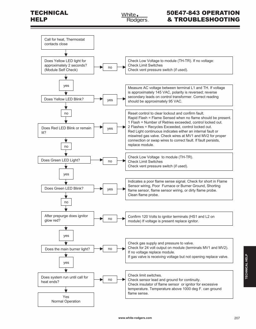
Reset control to clear lockout and confirm fault.Rapid Flash = Flame Sensed when no flame should be present. 1 Flash = Number of Retries exceeded, control locked out.2 Flashes = Recycles Exceeded, control locked out.Red Light continuous indicates either an internal fault or miswired gas valve. Check wires at MV1 and MV2 for proper connection or swap wires to correct fault. If fault persists, replace module.
Call for heat, Thermostat contacts close
Does Yellow LED light for approximately 2 seconds? (Module Self Check)
Does Yellow LED Blink?
Does Red LED Blink or remainlit?
Check Low Voltage to module (TH-TR). If no voltage:Check Limit SwitchesCheck vent pressure switch (if used).
Measure AC voltage between terminal L1 and TH. If voltage is approximately 145 VAC, polarity is reversed; reverse secondary leads on control transformer. Correct reading should be approximately 95 VAC.
Check Low Voltage to module (TH-TR).Check Limit SwitchesCheck vent pressure switch (if used).
Indicates a poor flame sense signal. Check for short in Flame Sensor wiring, Poor Furnace or Burner Ground, Shorting flame sensor, flame sensor wiring, or dirty flame probe.Clean flame probe.
Confirm 120 Volts to ignitor terminals (HS1 and L2 on module) If voltage is present replace ignitor.
Check gas supply and pressure to valve.Check for 24 volt output on module (terminals MV1 and MV2). If no voltage replace module. If gas valve is receiving voltage but not opening replace valve.
Check limit switches.Check sensor lead and ground for continuity.Check insulator of flame sensor or ignitor for excessive temperature. Temperature above 1000 deg F. can ground flame sense.
Does system run until call for heat ends?
Does the main burner light?
After prepurge does ignitor glow red?
Does Green LED Blink?
Does Green LED Light?
YesNormal Operation
TEC
HN
ICA
L H
ELP
www.white-rodgers.com 207