
5074 Background Note on Shale Gas
8
SHALE GAS BACKGROUND NOTE | Page This factsheet has been prepared for DECC by Dr C. Green of G Frac Technologies Ltd to assist understanding by non-specialists of the independent experts’ report about the induced seismicity during hydraulic fracturing at the Preese Hall site, Lancashire, NW England. What is a shale? Shale is a sedimentary rock that is predominantly comprised of very fine-grained clay particles deposited in a thinly laminated texture. These rocks were originally deposited as mud in low energy depositional environments, such as tidal flats and swamps, where the clay particles fall out of suspension. During the formation of these sediments, organic matter is also deposited, which is measured when quoting the Total Organic Content (TOC). Deep burial of this mud results in a layered rock called “Shale”, which actually describes the very fine grains and laminar nature of the sediment, not rock composition, which can therefore differ significantly between shales. What is different about shales and why are they hydraulically fracture stimulated? Matrix permeab ilities of typical shales (the ability of fluids to pass through them) are very low (often termed ultra low) compared to conventional low permeability oil and gas reservoirs (nanodarcy 10 -9 Darcy in shales versus millidarcy 10 - 2 in conventional sandstones) which means that hydrocarbons are effectively trapped and unable to flow under normal circumstances in shale, and usually only able to migrate out over geologic time. The slow migration of hydrocarbons from shales into shallower sandstone and carbonate reservoirs has been the source of most conventional oil and gas fields, hence shales have historically been thought of as source and seal rocks, rather than potential reservoirs, but much of the hydrocarbon still remains bound in the shale. What is shale gas? Shale gas is produced from organic-rich (>2% TOC according to USGS) shales. The very low permeability of shale means that it is classified as an unconventional reser voir for gas (or in some cases, oil) production for the following reasons: Conventional reservoirs – Convention al gas reser voirs contain ‘free’ gas in in terconne cted pore sp aces that can flow easily to the wellbore i.e. natural flow is possible. In convention al natural gas reservoirs, the gas is often sourced from organic-rich shales which has migrated to these nearby sandstone or carbonate reservoirs, over geologic time. Unconventional reservoirs – Unconven tional reser voirs prod uce from low pe rmeability ( tight and no w ultra tight) formations. The gas is often source d from the reservoir rock itself, adsorb ed onto the matrix. Due to the low permeability of these formations, it is necessary to stimulate the reservoir by creating a fracture network to give enough surface area to allow sufficient production from the additional ‘enhanced’ reservoir permeability. Are there other types of unconventional reservoirs? There are three main types of unconventional (UNCON) reservoirs presently being developed; while a fourth class, gas hydrates, is also being investigated for potential production. The permeabilities and associated gas type for UNCON’s are shown in Figure 1 (overleaf) and summarised below: 1. Tight Gas Sands (TGS) – Wells produce from low-porosity sandstones and carbonate reservoirs. The gas is sourced outside the reservoir and migrates into the reservoir over geological time. Some Tight Gas reservoirs have also been found to be sourced by underlying coal and shales source rocks, in the so- called Basin Centred Gas (BCG) accumulations. 2. Coal Bed Methane (CBM) – Wells produce from coal seams which act as source and reservoir to the produced gas. These wells often produce water in the initial production phase, as well as natural gas. Economic CBM reservoirs are normally shallow, as the coal matrix tends to have insufficient strength to maintain porosity at depth.
-
Upload
xaquin-rubido-muniz -
Category
Documents
-
view
221 -
download
0
Transcript of 5074 Background Note on Shale Gas
8/13/2019 5074 Background Note on Shale Gas
http://slidepdf.com/reader/full/5074-background-note-on-shale-gas 1/7
SHALE GAS BACKGROUND NOTE
| P a g e
This factsheet has been prepared for DECC by Dr C. Green of G Frac Technologies Ltd to assistunderstanding by non-specialists of the independent experts’ report about the induced seismicity during
hydraulic fracturing at the Preese Hall site, Lancashire, NW England.
What is a shale?
Shale is a sedimentary rock that is predominantly comprised of very fine-grained clay particles deposited in a thinlylaminated texture. These rocks were originally deposited as mud in low energy depositional environments, such astidal flats and swamps, where the clay particles fall out of suspension. During the formation of these sediments,organic matter is also deposited, which is measured when quoting the Total Organic Content (TOC). Deep burial ofthis mud results in a layered rock called “Shale”, which actually describes the very fine grains and laminar nature ofthe sediment, not rock composition, which can therefore differ significantly between shales.
What is different about shales and why are they hydraulically fracture stimulated?
Matrix permeabilities of typical shales (the ability of fluids to pass through them) are very low (often termed ultra low)compared to conventional low permeability oil and gas reservoirs (nanodarcy 10
-9 Darcy in shales versus millidarcy 10
-
2 in conventional sandstones) which means that hydrocarbons are effectively trapped and unable to flow under normal
circumstances in shale, and usually only able to migrate out over geologic time. The slow migration of hydrocarbonsfrom shales into shallower sandstone and carbonate reservoirs has been the source of most conventional oil and gasfields, hence shales have historically been thought of as source and seal rocks, rather than potential reservoirs, butmuch of the hydrocarbon still remains bound in the shale.
What is shale gas?
Shale gas is produced from organic-rich (>2% TOC according to USGS) shales. The very low permeability of shalemeans that it is classified as an unconventional reservoir for gas (or in some cases, oil) production for the followingreasons:
Conventional reservoirs – Conventional gas reservoirs contain ‘free’ gas in interconnected pore spaces thatcan flow easily to the wellbore i.e. natural flow is possible. In conventional natural gas reservoirs, the gas isoften sourced from organic-rich shales which has migrated to these nearby sandstone or carbonatereservoirs, over geologic time.
Unconventional reservoirs – Unconventional reservoirs produce from low permeability (tight and now ultratight) formations. The gas is often sourced from the reservoir rock itself, adsorbed onto the matrix. Due to thelow permeability of these formations, it is necessary to stimulate the reservoir by creating a fracture network togive enough surface area to allow sufficient production from the additional ‘enhanced’ reservoir permeability.
Are there other types of unconventional reservoirs?
There are three main types of unconventional (UNCON) reservoirs presently being developed; while a fourth class,gas hydrates, is also being investigated for potential production. The permeabilities and associated gas type forUNCON’s are shown in Figure 1 (overleaf) and summarised below:
1. Tight Gas Sands (TGS) – Wells produce from low-porosity sandstones and carbonate reservoirs. Thegas is sourced outside the reservoir and migrates into the reservoir over geological time. Some Tight Gasreservoirs have also been found to be sourced by underlying coal and shales source rocks, in the so-called Basin Centred Gas (BCG) accumulations.
2. Coal Bed Methane (CBM) – Wells produce from coal seams which act as source and reservoir to theproduced gas. These wells often produce water in the initial production phase, as well as natural gas.Economic CBM reservoirs are normally shallow, as the coal matrix tends to have insufficient strength tomaintain porosity at depth.
8/13/2019 5074 Background Note on Shale Gas
http://slidepdf.com/reader/full/5074-background-note-on-shale-gas 2/7
SHALE GAS BACKGROUND NOTE
| P a g e
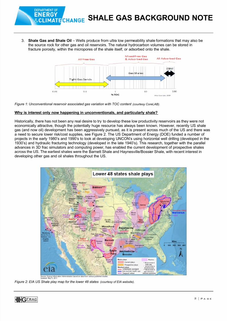
3. Shale Gas and Shale Oil – Wells produce from ultra low permeability shale formations that may also bethe source rock for other gas and oil reservoirs. The natural hydrocarbon volumes can be stored infracture porosity, within the micropores of the shale itself, or adsorbed onto the shale.
Figure 1: Unconventional reservoir associated gas variation with TOC content (courtesy CoreLAB).
Why is interest only now happening in unconventionals, and particularly shale?
Historically, there has not been any real desire to try to develop these low productivity reservoirs as they were noteconomically attractive, though the potentially huge resource has always been known. However, recently US shalegas (and now oil) development has been aggressively pursued, as it is present across much of the US and there wasa need to secure lower risk/cost supplies, see Figure 2. The US Department of Energy (DOE) funded a number ofprojects in the early 1980’s and 1990’s to look at developing UNCON’s using horizontal well drilling (developed in the1930’s) and hydraulic fracturing technology (developed in the late 1940’s). This research, together with the paralleladvances in 3D frac simulators and computing power, has enabled the current development of prospective shalesacross the US. The earliest shales were the Barnett Shale and Haynesville/Bossier Shale, with recent interest indeveloping other gas and oil shales throughout the US.
Figure 2: EIA US Shale play map for the lower 48 states (courtesy of EIA website).

8/13/2019 5074 Background Note on Shale Gas
http://slidepdf.com/reader/full/5074-background-note-on-shale-gas 3/7
SHALE GAS BACKGROUND NOTE
3 | P a g e
What is the history of shale?
Though shale gas has only recently started to attract attention as a potential reservoir, historically a shale gas wellwas the first commercial well in the US. A summary of Shale Gas history is outlined in Table 1.
Table 1: Shale Gas History Summary
How is shale development technology applied?
Each gas shale basin is different and each has a unique set of exploration criteria and operational challenges. Thetechnology was primarily developed in the Texas Barnett Shale and rolled out to other shale plays, often with a one-size-fits-all approach. However, there is now a realisation that Barnett shale technology needs to be adapted to otherplays in a structured and scientific manner. It has been stated that unconventional resources need unconventionaltechniques, but it is clear that the poorer the reservoir the better the technology and accuracy of data needed to be
able to fully characterize and develop each play. This means that typical shale plays are often a lot more expensiveand labour intensive than conventional plays to develop and the expertise needed to characterise reservoirs andoptimise stimulation treatments is highly specialized.
What is hydraulic fracturing?
Hydraulic fracturing involves the pumping of a (fracturing) fluid into a formation at a calculated, pre-determined rateand pressure to be able to crack the rock and create fractures in the target rock formation. Shale gas developmenttypically uses water or water-based fluids as the fracture fluids, mixed with a small amount of various additives (seelater). Sand is the usual “proppant” material pumped, and is needed to “prop” open the fractures once the pumping offluids has stopped and they have leaked off into the formation. Initially, fractures were considered to grow as halfpenny-shaped “wings” 180 degrees apart, as well as be identical in shape and size at any point in time. However, asresearch and technology have progressed we now know that created fracture growth is very complicated and innaturally-fractured reservoirs complex fracture growth results from a typical hydraulic fracture treatment.
What materials are used for fracturing?
There are two classes of materials injected during fracturing treatments, fracturing fluid, to carry the material to keepthe created fracture open and the solid proppant, to keep the created “fissure” open. The main environmentalconcerns relate to the additives used in the frac carrier fluid, as detailed below:
Fracturing Fluid: The fracturing fluid should have a number of properties that are optimised for each formation: becompatible with the formation rock, compatible with the formation fluid, generate sufficient pressure drop down thefracture to create a wide enough fracture, have sufficient lower viscosity to allow clean-up after the treatment, and becost effective. Water-based fluid are commonly used and “Slickwater” is the most common fluid used for shale gasfracturing, where the major chemical added is a surfactant polymer to reduce the surface tension or friction, so thatwater can be pumped at lower treating pressures. Other fluids that have been used are oil-based fluids, energisedfluids, foams and emulsions.
8/13/2019 5074 Background Note on Shale Gas
http://slidepdf.com/reader/full/5074-background-note-on-shale-gas 4/7
SHALE GAS BACKGROUND NOTE
4 | P a g e
Fracture Fluid Additives: Possible additives for frac fluids are listed below, but is should be stressed that not allchemicals are added for every job and in general as few additives as possible are added to avoid potential problemswith the reservoir and maximise production:
• Polymers – allow for an increase in the viscosity of the fluid, together with crosslinkers.• Crosslinkers – increase the viscosity of the linear polymer base gel.• Breakers – used to break the polymers and crosslink sites at formation temperature, for better clean-up.• Biocides – used to kill bacteria in the mix water.• Buffers – used to control the pH.• Fluid loss additives – used to control excessive fluid leak-off into the formation.• Stabilizers – used to keep the fluid viscous at higher temperature.
What techniques are used to analyse the location of the fractures created?
Fracture diagnostics are the techniques used to analyse the created fractures and involve analyzing data before (pre-frac), during (real time) and after (post-frac) hydraulic fracture treatments. Analysis is done to determine thedimensions of the created and also the effectively propped fracture. Fracture diagnostic techniques are divided intoseveral groups.
1) Direct Far Field Techniques: These comprise tiltmeter and microseismic fracture mapping techniques whichrequire delicate instrumentation to be placed in boreholes surrounding and near the well to be fracture treated.Microseismic fracture mapping typically relies on using a downhole receiver array of accelerometers, orgeophones, to locate ‘microearthquakes’ that are triggered by shear slippage in natural fractures surroundingthe hydraulic fracture. As with all monitoring and data collection techniques, however, the economics ofUNCONs means that typically they are considered marginal wells and the expense is often not justified untilthe resource has been proved. If the technology is used at the beginning of the development of a field,however, the data and knowledge gained have been shown to be cost effective in the long run oncedevelopment of the shale play begins in earnest.
2) Direct Near-Wellbore Techniques: These techniques are run in the well that is being fractured to locate theportion of fracture that is very near wellbore and consist of tracer logs, temperature logging, productionlogging, borehole image logging, downhole video logging, and calliper logging. In Shale gas plays, wheremultiple fractures are likely to exist, the reliability of these direct near-wellbore techniques can often be poor. As such, very few of these direct near-wellbore techniques are used on a routine basis to evaluate hydraulicfracture and if deployed they are used in conjunction with other techniques.
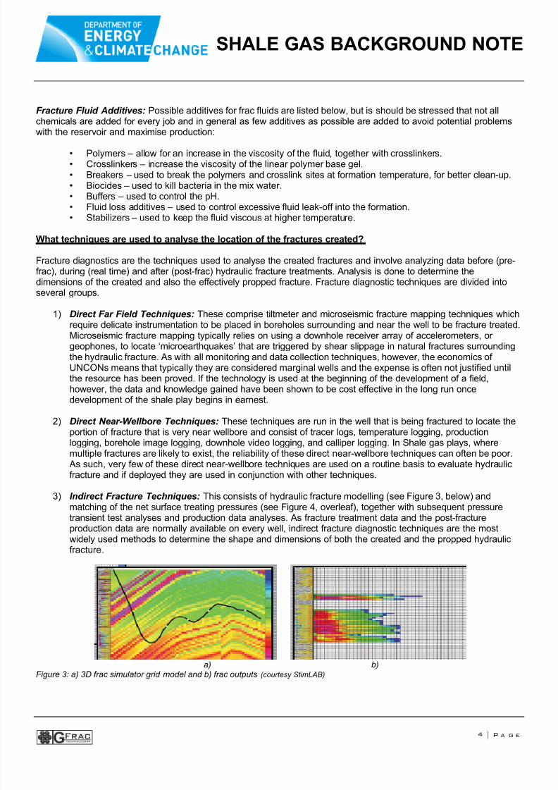
3) Indirect Fracture Techniques: This consists of hydraulic fracture modelling (see Figure 3, below) andmatching of the net surface treating pressures (see Figure 4, overleaf), together with subsequent pressuretransient test analyses and production data analyses. As fracture treatment data and the post-fractureproduction data are normally available on every well, indirect fracture diagnostic techniques are the mostwidely used methods to determine the shape and dimensions of both the created and the propped hydraulic
fracture.
a) b)Figure 3: a) 3D frac simulator grid model and b) frac outputs (courtesy StimLAB)
8/13/2019 5074 Background Note on Shale Gas
http://slidepdf.com/reader/full/5074-background-note-on-shale-gas 5/7
SHALE GAS BACKGROUND NOTE
5 | P a g e
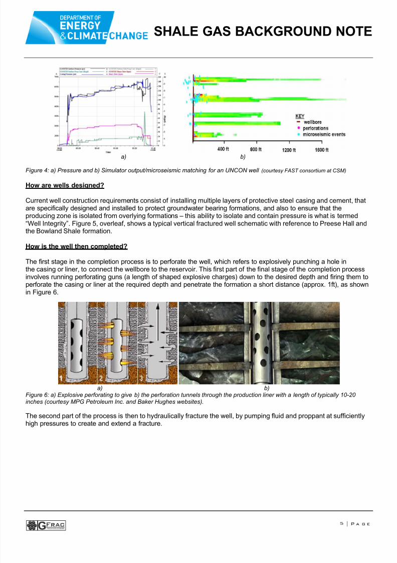
a) b)
Figure 4: a) Pressure and b) Simulator output/microseismic matching for an UNCON well (courtesy FAST consortium at CSM)
How are wells designed?
Current well construction requirements consist of installing multiple layers of protective steel casing and cement, thatare specifically designed and installed to protect groundwater bearing formations, and also to ensure that theproducing zone is isolated from overlying formations – this ability to isolate and contain pressure is what is termed“Well Integrity”. Figure 5, overleaf, shows a typical vertical fractured well schematic with reference to Preese Hall andthe Bowland Shale formation.
How is the well then completed?
The first stage in the completion process is to perforate the well, which refers to explosively punching a hole inthe casing or liner, to connect the wellbore to the reservoir. This first part of the final stage of the completion processinvolves running perforating guns (a length of shaped explosive charges) down to the desired depth and firing them toperforate the casing or liner at the required depth and penetrate the formation a short distance (approx. 1ft), as shownin Figure 6.
a) b)
Figure 6: a) Explosive perforating to give b) the perforation tunnels through the production liner with a length of typically 10-20inches (courtesy MPG Petroleum Inc. and Baker Hughes websites).
The second part of the process is then to hydraulically fracture the well, by pumping fluid and proppant at sufficientlyhigh pressures to create and extend a fracture.

8/13/2019 5074 Background Note on Shale Gas
http://slidepdf.com/reader/full/5074-background-note-on-shale-gas 6/7
SHALE GAS BACKGROUND NOTE
6 | P a g e
Figure 5: Typical vertical hydraulically fractured well schematic.
How are hydraulic fracture treatments carried out?
Initially, fluid is injected that does not contain any propping agent, called ‘pad’, which is injected to create a fracturethat usually grows up, out and down, see Figure 7a. The pad creates a fracture that is then wide enough to beginaccepting a propping agent material. The pad is then followed by the proppant “slurry”, a mix of the carrier fluid andproppant material. The purpose of the propping agent is to ‘prop open’ the created fracture, once the pumpingoperation ceases and the fracture closes. In deep reservoirs, man-made ceramic beads are sometimes used to propopen the fractures but in shallow reservoirs, sand can be used and remains the most common proppant. Once thefracture has initiated, fluid is continually pumped into the wellbore to extend the created fracture and develop afracture network. Each formation has different properties and in-situ stresses, so that each hydraulic fracture job isunique and different and is specifically designed for that well by a hydraulic frac specialist (see Figure 7b, overleaf).The process of designing hydraulic fracture treatments involves identifying properties of the target formation includingestimating fracture treating pressure, amount of material and the desired length for optimal economics.

8/13/2019 5074 Background Note on Shale Gas
http://slidepdf.com/reader/full/5074-background-note-on-shale-gas 7/7
SHALE GAS BACKGROUND NOTE
7 | P a g e
a) b) Figure 7: a) The hydraulic fracture process and b) resultant matched 3D simulator outputs.