503 WELLS MANUFACTURING - Parts Towndownload.partstown.com/is-bin/intershop.static/WFS/Reedy... ·...
52
WELLS MANUFACTURING 10 Sunnen Dr., St. Louis, MO 63143 telephone: 314-678-6314 fax: 314-781-2714 www.wellsbloomfield.com IMPORTANT: DO NOT DISCARD THIS MANUAL This manual is considered to be part of the appliance and is to be given to the OWNER or MANAGER of the restaurant, or to the person responsible for TRAINING OPERATORS of this appliance. Additional manuals are available from your WELLS DEALER. THIS MANUAL MUST BE READ AND UNDERSTOOD BY ALL PERSONS USING OR INSTALLING THIS APPLIANCE. Contact your WELLS DEALER if you have any questions concerning installation, operation or maintenance of this equipment. 503 p/n 2M-304989 Rev. L M503 150108 OWNERS MANUAL WVF886 SERIES DUAL FRYPOT AUTO-LIFT FRYER with UNIVERSAL HOOD MODELS: WVF886 WVF886RW WVF886RWT Includes INSTALLATION USE & CARE EXPLODED VIEW PARTS LIST WIRING DIAGRAM Model WVF886RW
Transcript of 503 WELLS MANUFACTURING - Parts Towndownload.partstown.com/is-bin/intershop.static/WFS/Reedy... ·...

WELLS MANUFACTURING10 Sunnen Dr., St. Louis, MO 63143
telephone: 314-678-6314fax: 314-781-2714
www.wellsbloomfield.com
IMPORTANT: DO NOT DISCARD THIS MANUALThis manual is considered to be part of the appliance and is to be given to the OWNER or MANAGER of the restaurant, or to the person responsible for TRAINING OPERATORS of this appliance. Additional manuals are available from your WELLS DEALER.
THIS MANUAL MUST BE READ AND UNDERSTOOD BY ALL PERSONS USING OR INSTALLING THIS APPLIANCE. Contact your WELLS DEALER if you have anyquestions concerning installation, operation or maintenance of this equipment.
503
p/n 2M-304989 Rev. L M503 150108
OWNERS MANUAL
WVF886 SERIES
DUAL FRYPOTAUTO-LIFT FRYER
withUNIVERSAL HOOD
MODELS:WVF886
WVF886RWWVF886RWT
IncludesINSTALLATIONUSE & CARE
EXPLODED VIEWPARTS LIST
WIRING DIAGRAM
Model WVF886RW
503
p/n
2M
-304
989
Ow
ners
Man
ual
WV
F-88
6 Ve
ntle
ss F
ryer
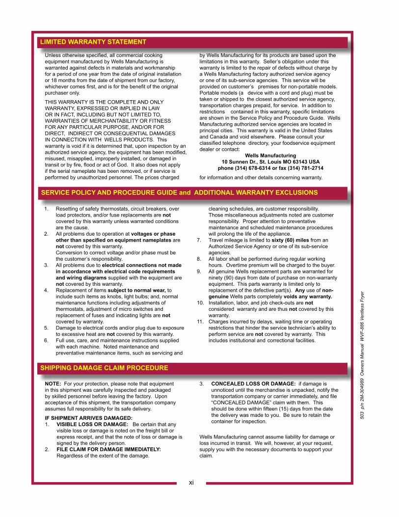
Unless otherwise specified, all commercial cooking equipment manufactured by Wells Manufacturing is warranted against defects in materials and workmanship for a period of one year from the date of original installation or 18 months from the date of shipment from our factory, whichever comes first, and is for the benefit of the original purchaser only.
THIS WARRANTY IS THE COMPLETE AND ONLY WARRANTY, EXPRESSED OR IMPLIED IN LAW OR IN FACT, INCLUDING BUT NOT LIMITED TO, WARRANTIES OF MERCHANTABILITY OR FITNESS FOR ANY PARTICULAR PURPOSE, AND/OR FOR DIRECT, INDIRECT OR CONSEQUENTIAL DAMAGES IN CONNECTION WITH WELLS PRODUCTS. This warranty is void if it is determined that, upon inspection by an authorized service agency, the equipment has been modified, misused, misapplied, improperly installed, or damaged in transit or by fire, flood or act of God. It also does not apply if the serial nameplate has been removed, or if service is performed by unauthorized personnel. The prices charged
by Wells Manufacturing for its products are based upon the limitations in this warranty. Seller’s obligation under this warranty is limited to the repair of defects without charge by a Wells Manufacturing factory authorized service agency or one of its sub-service agencies. This service will be provided on customer’s premises for non-portable models. Portable models (a device with a cord and plug) must be taken or shipped to the closest authorized service agency, transportation charges prepaid, for service. In addition to restrictions contained in this warranty, specific limitations are shown in the Service Policy and Procedure Guide. Wells Manufacturing authorized service agencies are located in principal cities. This warranty is valid in the United States and Canada and void elsewhere. Please consult your classified telephone directory, your foodservice equipment dealer or contact:
Wells Manufacturing10 Sunnen Dr., St. Louis MO 63143 USA
phone (314) 678-6314 or fax (314) 781-2714
for information and other details concerning warranty.
LIMITED WARRANTY STATEMENT
SERVICE POLICY AND PROCEDURE GUIDE and ADDITIONAL WARRANTY EXCLUSIONS
NOTE: For your protection, please note that equipment in this shipment was carefully inspected and packaged by skilled personnel before leaving the factory. Upon acceptance of this shipment, the transportation company assumes full responsibility for its safe delivery.
IF SHIPMENT ARRIVES DAMAGED:1. VISIBLE LOSS OR DAMAGE: Be certain that any
visible loss or damage is noted on the freight bill or express receipt, and that the note of loss or damage is signed by the delivery person.
2. FILE CLAIM FOR DAMAGE IMMEDIATELY: Regardless of the extent of the damage.
3. CONCEALED LOSS OR DAMAGE: if damage is unnoticed until the merchandise is unpacked, notify the
transportation company or carrier immediately, and file “CONCEALED DAMAGE” claim with them. This should be done within fifteen (15) days from the date the delivery was made to you. Be sure to retain the container for inspection.
Wells Manufacturing cannot assume liability for damage or loss incurred in transit. We will, however, at your request, supply you with the necessary documents to support your claim.
SHIPPING DAMAGE CLAIM PROCEDURE
xi
1. Resetting of safety thermostats, circuit breakers, over load protectors, and/or fuse replacements are not covered by this warranty unless warranted conditions are the cause.
2. All problems due to operation at voltages or phase other than specified on equipment nameplates are not covered by this warranty.
Conversion to correct voltage and/or phase must be the customer’s responsibility.
3. All problems due to electrical connections not made in accordance with electrical code requirements and wiring diagrams supplied with the equipment are not covered by this warranty.
4. Replacement of items subject to normal wear, to include such items as knobs, light bulbs; and, normal
maintenance functions including adjustments of thermostats, adjustment of micro switches and replacement of fuses and indicating lights are not covered by warranty.5. Damage to electrical cords and/or plug due to exposure
to excessive heat are not covered by this warranty.6. Full use, care, and maintenance instructions supplied
with each machine. Noted maintenance and preventative maintenance items, such as servicing and
cleaning schedules, are customer responsibility. Those miscellaneous adjustments noted are customer
responsibility. Proper attention to preventative maintenance and scheduled maintenance procedures
will prolong the life of the appliance.7. Travel mileage is limited to sixty (60) miles from an
Authorized Service Agency or one of its sub-service agencies.
8. All labor shall be performed during regular working hours. Overtime premium will be charged to the buyer.
9. All genuine Wells replacement parts are warranted for ninety (90) days from date of purchase on non-warranty equipment. This parts warranty is limited only to replacement of the defective part(s). Any use of non-genuine Wells parts completely voids any warranty.
10. Installation, labor, and job check-outs are not considered warranty and are thus not covered by this
warranty.11. Charges incurred by delays, waiting time or operating
restrictions that hinder the service technician’s ability to perform service are not covered by warranty. This includes institutional and correctional facilities.
503
p/n
2M
-304
989
Ow
ners
Man
ual
WV
F-88
6 Ve
ntle
ss F
ryer
WARRANTY .......................................................... xiSPECIFICATIONS ................................................. 1FEATURES & OPERATING CONTROLS ............. 2PRECAUTIONS & GENERAL INFORMATION ..... 6AGENCY LISTING INFORMATION ...................... 7INSTALLATION ..................................................... 8OPERATION ......................................................... 13CLEANING INSTRUCTIONS ................................ 17DISPOSAL OF USED OIL ..................................... 22MAINTENANCE (Periodic Cleaning) ..................... 23TROUBLESHOOTING SUGGESTIONS ............... 24 MAINTENANCE SCHEDULES ............................. 26MSDS (Ansulex Low pH) ....................................... 29ANSUL® COMPONENTS ..................................... 31EXPLODED VIEW & PARTS LIST ......................... 32—43WIRING DIAGRAM ............................................... 44 –46PARTS & SERVICE .............................................. 49CUSTOMER SERVICE DATA .............................. 49
Thank You for purchasing this Wells Manufacturing appliance.
Proper installation, professional operation and consistent maintenance of this appliance will ensure that it gives you the very best performance and a long, economical service life.
This manual contains the information needed to properly install this appliance, and to use and care for the appliance in a manner which will ensure its optimum performance.
TABLE OF CONTENTS
INTRODUCTION
1
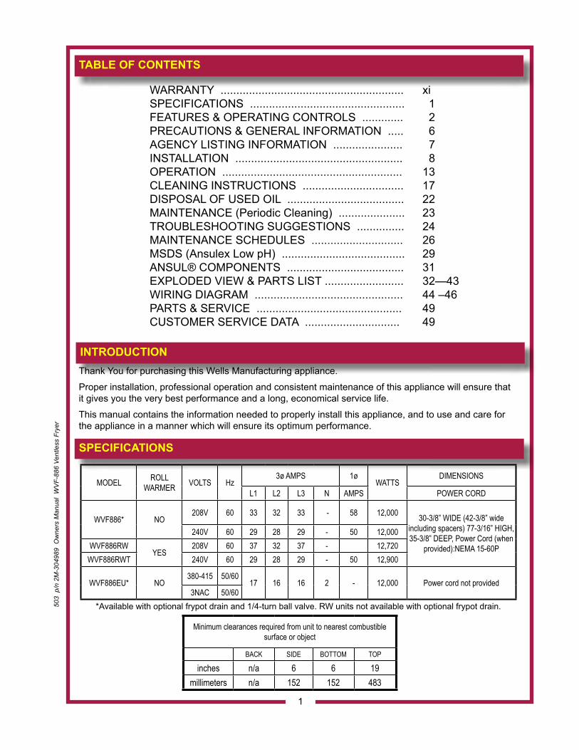
SPECIFICATIONS
Minimum clearances required from unit to nearest combustible surface or object
BACK SIDE BOTTOM TOP
inches n/a 6 6 19millimeters n/a 152 152 483
MODEL ROLL WARMER VOLTS Hz
3ø AMPS 1øWATTS
DIMENSIONS
L1 L2 L3 N AMPS POWER CORD
WVF886* NO208V 60 33 32 33 - 58 12,000 30-3/8” WIDE (42-3/8” wide
including spacers) 77-3/16” HIGH, 35-3/8” DEEP, Power Cord (when
provided):NEMA 15-60P
240V 60 29 28 29 - 50 12,000WVF886RW
YES 208V 60 37 32 37 - 12,720
WVF886RWT 240V 60 29 28 29 - 50 12,900
WVF886EU* NO380-415 50/60
17 16 16 2 - 12,000 Power cord not provided3NAC 50/60
*Available with optional frypot drain and 1/4-turn ball valve. RW units not available with optional frypot drain.
FEATURES & OPERATING CONTROLS
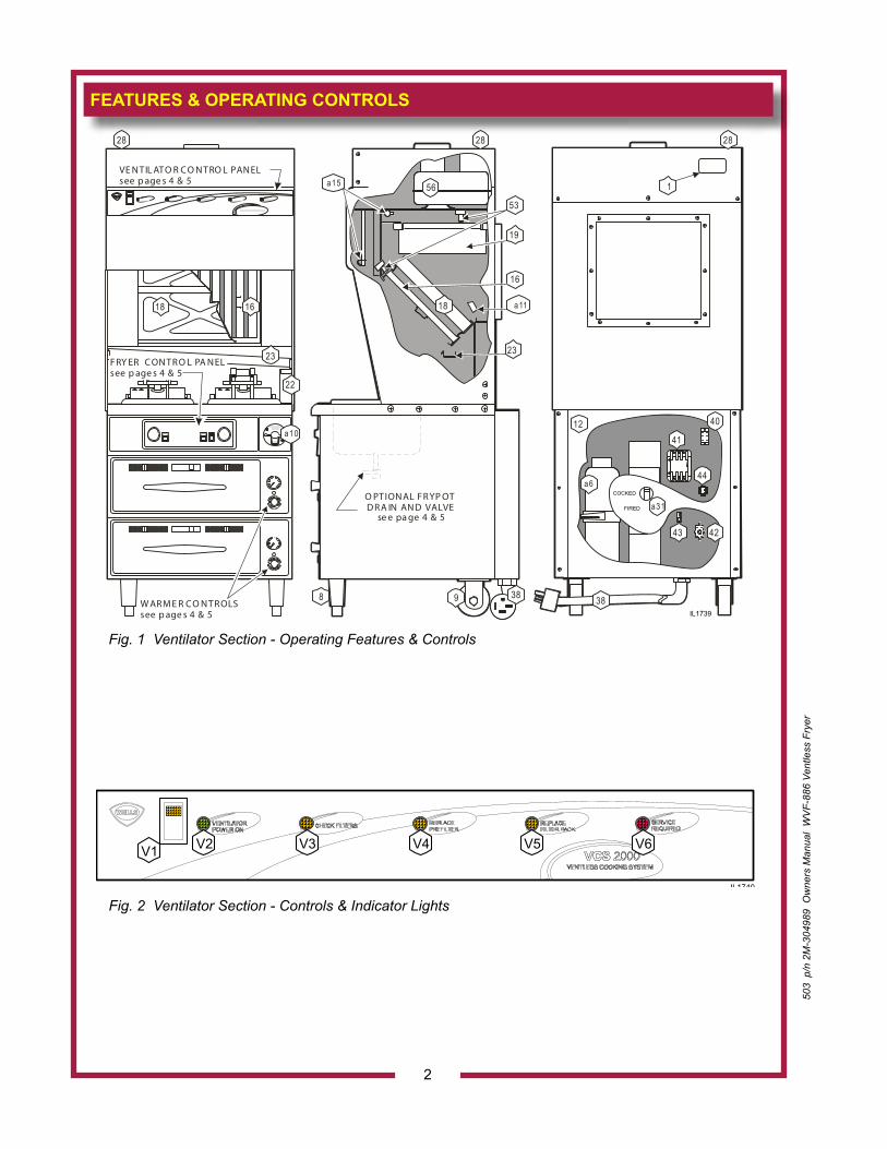
Fig. 1 Ventilator Section - Operating Features & Controls
2
Fig. 2 Ventilator Section - Controls & Indicator Lights
503
p/n
2M
-304
989
Ow
ners
Man
ual
WV
F-88
6 Ve
ntle
ss F
ryer
VENTILATORPOWER ON
REPLACEFILTER PACK
VCS 2000V1 V2 V3 V4 V5 V6
IL1740
1241
44
4243
40
a6
a31
18 16
22
23
VE N TIL ATO R C O N TRO L PAN ELsee p age s 4 & 5
W AR M E R C O N TR OLSsee p age s 4 & 5
FRY ER C ON TR O L PA N ELsee p age s 4 & 5
38
a10
56
28 28 28
19
16
18
23
1
8
a15
a11
53
389
O PTION AL FR YP OTD R A IN AN D VALVE
se e pa ge 4 & 5
IL1739
COCKED
FIRED
503
p/n
2M
-304
989
Ow
ners
Man
ual
WV
F-88
6 Ve
ntle
ss F
ryer
FEATURES & OPERATING CONTROLS (continued)
3* See PRECAUTIONS & GENERAL INFORMATION, pages 6 & 7 for special procedures regarding prefilters and filter packs.
ITEM DESCRIPTION COMMENTVENTILATOR SECTION
1 NAMEPLATELists Manufacturer, Model and Serial Number information.Also lists electrical specifications.
a6. FIRE SUPPRESSION AGENT TANK (1.5 gal.) Container for Ansulex™ Low-pH liquid fire suppression liquid.
8 ADJUSTABLE (FRONT) LEG Allows the unit to be leveled.9 RIGID (REAR) CASTER Allows the unit to be easily positioned by lifting the front of the unit slightly.
a10. MANUAL PULL STATION Provides a means of manual activation of the fire suppression system. PULL ONLY IN CASE OF FIRE!
a11. FUSIBLE LINKS Automatically activates fire suppression system in the event of fire in the fryer.
12 LOWER REAR ACCESS PANEL Allows access to Ansul® fire suppression agent tank (a6) and controls also access to main power contactor (41).
a15. DISCHARGE NOZZLE Fire suppression media discharges here (2 places).16 GREASE BAFFLE Extracts and drains most grease and moisture from the air flow.
18 PRE-FILTER ASSEMBLY Comprises the PRE-FILTER FRAME and a replaceable PRE-FILTER. Stops larger particles of grease from reaching the FILTER PACK for reduced maintenance costs.
19 HEPA/CHARCOAL FILTER PACK Stops most grease and smoke particles. Also assists in some cooking odor removal.
22 GREASE CUP Collects grease/moisture drained from grease trough (23).23 GREASE TROUGH Directs grease/moisture removed by grease baffle to grease cup.
28 VENTILATOR EXHAUST DUCTExit point for ventilator airflow - on top left rear of unit.DO NOT BLOCK
a31. STATUS INDICATOR Displays status of fire suppression system (COCKED - FIRED). If FIRED, a buzzer will sound continuously.
38 POWER CORD (WHEN PROVIDED) 6’ cord and cap. Plug for NEMA 15-60R (receptacle by user).
40 WARMER RELAY Provides power to roll warmer section. Energized at all times except during fire safety shut-down.
41 POWER CONTACTOR Energizes fryer only while ventilator section is sensed as operational.42 BUILDING FIRE ALARM RELAY Reports fire alarm condition to building fire management system.43 GROUND LUG Ground wire of power cord connects here.44 INTERLOCK TERMINAL Provides connection for shut-down control by building fire management system.
53 FILTER INTERLOCK SWITCHES Proper installation of grease baffle and filter pack close these switches in ventilator sensor circuit.
56 VENTILATOR FAN Provides air movement for ventilation.
VENTILATOR CONTROL AND INDICATOR PANEL
V1 POWER SWITCH Energizes blower motor. If, after 10 seconds, proper conditions are met, appliance is energized.
V2 POWER ON INDICATOR GREEN. Glows when POWER switch is ON.
V3 CHECK FILTERS ALARM INDICATOR AMBER. Glows if one or more filters are out of position. Check all filters and baffles for proper installation.
V4* REPLACE PREFILTER ALARM INDICATOR
AMBER. Glows when PREFILTER is approaching the end of its service life and must soon be replaced.
V5* REPLACE FILTER PACK ALARM INDICATOR
AMBER. Glows when FILTER PACK is approaching the end of its service life and must soon be replaced.
V6* SERVICE REQUIRED ALARM INDICATORRED. Glows when PREFILTER and/or FILTER PACK has reached the end of its service life and is too loaded to allow sufficient air flow. Filter MUST be replaced. Appliance is SHUT DOWN until expended filters are replaced.
IL2141
Electric Shock HazardDisconnect power beforeremoving fuses.
CAUTION:!
FUSE
FUSEHOLDER
ELEMENT HEAD(SHOWN LOWERED)
BASKET LIFT
HEATING ELEMENTS(ELEMENT HEADSHOWN RAISED)
ELEMENTLIFTINGHANDLE
FRYPOTHANDLES
FRYPOT
F.01F.02
F.04
F.05
F.06 F.07
F.08
ELEMENTHEADSUPPORTROD
FRYERBASKET
FRYPOT DRAIN(OPTIONAL)
ANSUL®PUSH PUSH
F.01 F.02F.02
W.06
W.06
W.05
W.07
W.04W.01
W.09
W.03
W.02
W.08
RWT-STYLE
RW-STYLE
DRAWERINSERT PAN
HUMITROLRACK
FEATURES & OPERATING CONTROLS (continued)
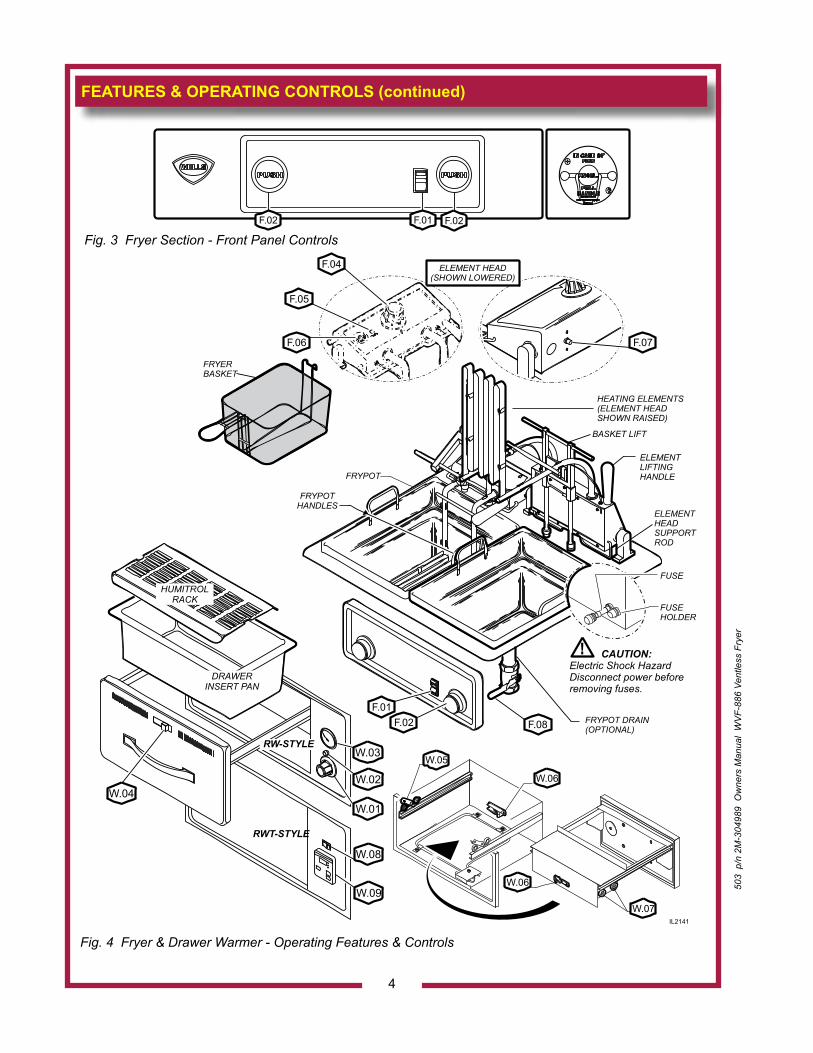
Fig. 4 Fryer & Drawer Warmer - Operating Features & Controls
Fig. 3 Fryer Section - Front Panel Controls
4
503
p/n
2M
-304
989
Ow
ners
Man
ual
WV
F-88
6 Ve
ntle
ss F
ryer
503
p/n
2M
-304
989
Ow
ners
Man
ual
WV
F-88
6 Ve
ntle
ss F
ryer
FEATURES & OPERATING CONTROLS (continued)
5
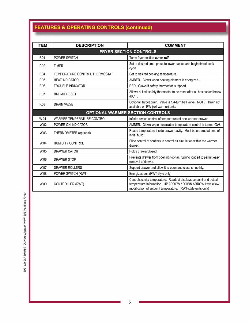
ITEM DESCRIPTION COMMENTFRYER SECTION CONTROLS
F.01 POWER SWITCH Turns fryer section on or off.
F.02 TIMER Set to desired time, press to lower basket and begin timed cook cycle.
F.04 TEMPERATURE CONTROL THERMOSTAT Set to desired cooking temperature.F.05 HEAT INDICATOR AMBER. Glows when heating element is energized.F.06 TROUBLE INDICATOR RED. Glows if safety thermostat is tripped.
F.07 HI-LIMIT RESET Allows hi-limit safety thermostat to be reset after oil has cooled below 400ºF.
F.08 DRAIN VALVE Optional frypot drain. Valve is 1/4-turn ball valve. NOTE: Drain not available on RW (roll warmer) units
OPTIONAL WARMER SECTION CONTROLS W.01 WARMER TEMPERATURE CONTROL Infinite switch control of temperature of one warmer drawer. W.02 POWER ON INDICATOR AMBER. Glows when associated temperature control is turned ON.
W.03 THERMOMETER (optional) Reads temperature inside drawer cavity. Must be ordered at time of initial build.
W.04 HUMIDITY CONTROL Slide control of shutters to control air circulation within the warmer drawer.
W.05 DRAWER CATCH Holds drawer closed.
W.06 DRAWER STOP Prevents drawer from opening too far. Spring loaded to permit easy removal of drawer.
W.07 DRAWER ROLLERS Support drawer and allow it to open and close smoothly. W.08 POWER SWITCH (RWT) Energizes unit (RWT-style only)
W.09 CONTROLLER (RWT)Controls cavity temperature. Readout displays setpoint and actual temperature information. UP ARROW / DOWN ARROW keys allow modification of setpoint temperature. (RWT-style units only)
NOTE: Fire suppression system and all associated components must only be serviced by an authorized Ansul® Distributor. All setup, charging, repair and/or adjustment of the fire suppression system must be performed by an Authorized Ansul® Distributor ONLY.IMPORTANT: If a remote pull station is installed, both rear casters (9) must be replaced with legs to deter moving the unit. MOVING AN APPLIANCE WITH A REMOTE PULL STATION WILL DISCHARGE THE FIRE SUPPRESSION SYSTEM.This appliance is for use in commercial establishments only.This appliance is intended to prepare food for human consumption. No other use is authorized by the manufacturer or its agents.Operators of this appliance must be familiar with the appliance use, limitations and associated restrictions. Operating instructions must be read and understood by all persons using or installing this appliance.Cleanliness of this appliance is essential to good sanitation. Read and follow all included cleaning instructions and schedules to ensure the safety of the food product.Disconnect this appliance from electrical power before performing any maintenance or servicing.Do not splash or pour water on, in or over any exposed element, control, control panel or wiring. The technical content of this manual, including any wiring diagrams, schematics, parts breakdown illustrations and/or adjustment procedures, is intended for use by qualified technical personnel.Any procedure which requires the use of tools must be performed by a qualified technician.This manual is considered to be a permanent part of the appliance. This manual and all supplied instructions, diagrams, schematics, parts breakdown illustrations, notices and labels must remain with the appliance if it is sold or moved to another location.This appliance is made in the USA. Unless otherwise noted, this appliance has American sizes on all hardware.
PRECAUTIONS AND GENERAL INFORMATION
CAUTION:RISK OFDAMAGE
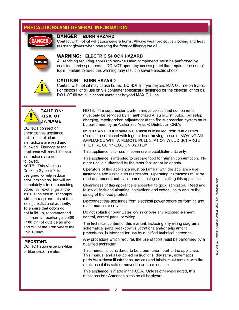
DO NOT connect orenergize this applianceuntil all installationinstructions are read and followed. Damage to theappliance will result if these instructions are notfollowed.NOTE: This Ventless Cooking System™ is designed to help reduce odor emissions, but will not completely eliminate cooking odors. Air exchange at the installation site must comply with the requirements of the local jurisdictional authority. To ensure that odors do not build-up, recommended minimum air exchange is 300 - 400 cfm of outside air into and out of the area where the unit is used.
IMPORTANT:DO NOT submerge pre-filter or filter pack in water.
6
DANGER: BURN HAZARDContact with hot oil will cause severe burns. Always wear protective clothing and heat resistant gloves when operating the fryer or filtering the oil.
WARNING: ELECTRIC SHOCK HAZARDAll servicing requiring access to non-insulated components must be performed by qualified service personnel. DO NOT open any access panel that requires the use of tools. Failure to heed this warning may result in severe electric shock.
CAUTION: BURN HAZARDContact with hot oil may cause burns. DO NOT fill fryer beyond MAX OIL line on frypot.For disposal of oil use only a container specifically designed for the disposal of hot oil. DO NOT fill hot oil disposal container beyond MAX OIL line.
503
p/n
2M
-304
989
Ow
ners
Man
ual
WV
F-88
6 Ve
ntle
ss F
ryer
503
p/n
2M
-304
989
Ow
ners
Man
ual
WV
F-88
6 Ve
ntle
ss F
ryer
AGENCY LISTING INFORMATION
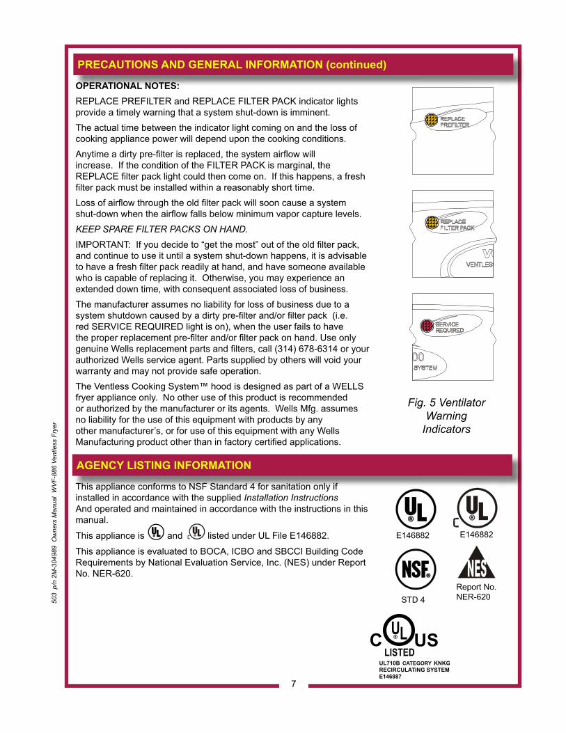
OPERATIONAL NOTES: REPLACE PREFILTER and REPLACE FILTER PACK indicator lights provide a timely warning that a system shut-down is imminent. The actual time between the indicator light coming on and the loss of cooking appliance power will depend upon the cooking conditions.Anytime a dirty pre-filter is replaced, the system airflow will increase. If the condition of the FILTER PACK is marginal, the REPLACE filter pack light could then come on. If this happens, a fresh filter pack must be installed within a reasonably short time. Loss of airflow through the old filter pack will soon cause a system shut-down when the airflow falls below minimum vapor capture levels. KEEP SPARE FILTER PACKS ON HAND.
IMPORTANT: If you decide to “get the most” out of the old filter pack, and continue to use it until a system shut-down happens, it is advisable to have a fresh filter pack readily at hand, and have someone available who is capable of replacing it. Otherwise, you may experience an extended down time, with consequent associated loss of business.The manufacturer assumes no liability for loss of business due to a system shutdown caused by a dirty pre-filter and/or filter pack (i.e. red SERVICE REQUIRED light is on), when the user fails to have the proper replacement pre-filter and/or filter pack on hand. Use only genuine Wells replacement parts and filters, call (314) 678-6314 or your authorized Wells service agent. Parts supplied by others will void your warranty and may not provide safe operation.The Ventless Cooking System™ hood is designed as part of a WELLS fryer appliance only. No other use of this product is recommended or authorized by the manufacturer or its agents. Wells Mfg. assumes no liability for the use of this equipment with products by any other manufacturer’s, or for use of this equipment with any Wells Manufacturing product other than in factory certified applications.
PRECAUTIONS AND GENERAL INFORMATION (continued)
Fig. 5 Ventilator Warning
Indicators
7
STD 4
E146882
This appliance conforms to NSF Standard 4 for sanitation only ifinstalled in accordance with the supplied Installation InstructionsAnd operated and maintained in accordance with the instructions in this manual.
This appliance is and listed under UL File E146882.
This appliance is evaluated to BOCA, ICBO and SBCCI Building Code Requirements by National Evaluation Service, Inc. (NES) under Report No. NER-620.
Report No. NER-620
E146882
INSTALLATIONNOTE: DO NOT discardthe carton or other packingmaterials until you haveinspected the appliance forhidden damage and tested it for proper operation.Refer to SHIPPING DAMAGE CLAIM PROCEDURE on the inside front cover of thismanual.
WARNING:RISK OF INJURY
Installation procedures must be performed by a qualified technician with full knowledge of all applicable electrical codes. Failure can result in personal injury and property damage.
UNPACKING & INSPECTIONCarefully remove the appliance from the carton. Remove all protective plastic film, packing materials and accessories from the Appliance before connecting electrical power or otherwise performing any installation procedure.Carefully read all instructions in this manual and the Installation Instruction Sheet packed with the appliance before starting any installation.Read and understand all labels and diagrams attached to the appliance.Carefully account for all components and accessories before discarding packing materials. Store these components in or near the appliance for later use. To prevent loss, these items should be installed as soon as possible.1 ea. FIRE SUPPRESSION AGENT (ANSULEX® Low pH, 1.5 GAL.)
See Material Safety Data Sheet, page 27.1 ea. FIRE SUPPRESSION MEDIA TANK1 ea. FIRE SUPPRESSION TANK CHARGING CARTRIDGE1 ea. GREASE BAFFLE1 ea. FILTER PACK ASSEMBLY1 ea. PRE-FILTER HOLDER with PRE-FILTER1 ea. GREASE CUP1 ea. GREASE TROUGH2 ea. 6” SIDE SPACERS1 ea. LITERATURE PACKAGE2 ea. FRYPOTS (with or without optional drain)2 ea. FRYER BASKETSAdditionally:2 ea. DRAWER INSERTS (if ordered with warmer drawers)2 ea. HUMITROL RACKS (if ordered with warmer drawers)2 ea. DRAIN VALVE ASSEMBLIES (for units with optional drain only)
SETUPSetup the appliance only on a firm level surface. Non-combustible material is recommended.Refer to the Installation Instruction Sheet for required clearances. Maintain required clearances between the appliance and adjacent combustible surfaces. Verify 6” left and right side clearances to combustible construction. This appliance requires a minimum of 8 ft (96”) (floor to overhead) to allow for adequate exhaust.Verify that the VENTILATOR HOOD ASSEMBLY is properly and securely assembled to the cooking appliance before beginning the installation procedure.If a remote manual pull station is to be installed, replace the rear casters with legs.Level the unit after it is in its final position. Using a spirit level, verify that the unit is level front-to-back and side-to-side.Avoid storing flammable or combustible materials near the appliance.
8
503
p/n
2M
-304
989
Ow
ners
Man
ual
WV
F-88
6 Ve
ntle
ss F
ryer
503
p/n
2M
-304
989
Ow
ners
Man
ual
WV
F-88
6 Ve
ntle
ss F
ryer
SERVICE TECHNICIAN INSTALLATION NOTESAn Ansul® technician must charge and arm the fire suppression system before the ventilator blower will operate. See page 10.Installation and start up must be performed by an Authorized Installation Company.Installer must complete the WARRANTY REGISTRATION form, and record appliance installation particulars on the CUSTOMER SERVICE DATA form in this manual. Certain codes require cooking equipment to be restrained with a RESTRAINT DEVICE. It is the RESPONSIBILITY OF THE INSTALLER to check with the authority having jurisdiction, in order to ascertain the applicability of this requirement to this specific EQUIPMENT installation. Any restraint device must allow access to the back and sides of the unit to provide for servicing and maintenance, and must not interfere with the operation of the FIRE SUPPRESSION SYSTEM.
ELECTRICAL INSTALLATIONRefer to the nameplate on the cooking appliance to verify the ELECTRICAL SERVICE POWER. Voltage and phase must match the nameplate specifications, and available electrical service amperage must meet or exceed the specifications listed on page 1. Incoming wiring must comply with National Electrical Code specifications. All 3ø fryer / universal hood appliances (except EU units) ship from the factory with a 3ø cordset.All 1ø fryer / universal hood appliances; and, all EU fryer / universal hood appliances must be wired directly to the electrical circuit. Most jurisdictions require an approved electrical disconnect to be installed in the branch circuit, in near proximity to the appliance.Field conversion of 3ø appliances to 1ø is neither recommended nor authorized by Wells Manufacturing Co.
IMPORTANT!Verify that this VENTILATOR and food cooking equipment installation is in compliance with the specifications listed in this manual, with local code requirements, and in accordance with N.F.P.A 96 (THE STANDARD FOR VENTILATION CONTROL AND FIRE PROTECTION OF COMMERCIAL COOKING OPERATIONS - current edition).
THIS IS THE RESPONSIBILITY
OF THE INSTALLER
DANGER ELECTRIC SHOCK HAZARD
ELECTRIC CONNECTIONS MUST BE MADE BY A LICENSED ELECTRICIANElectrical shock will cause death or serious injury.
NOTE: This appliance requires a dedicated electrical branch circuit with 50 Amp protection for 3ø; or, 80 Amp protection for 1ø.
IMPORTANT:Contact a licensed electrician to install and connect electrical power to the appliance.
IMPORTANT:Damage due to beingconnected to the wrong voltage or phase is NOT covered by warranty.
INSTALLATION (continued)
9
INSTALLATION (continued)
FIRE SUPPRESSION SYSTEM INSTALLATION1. Any REMOTE MANUAL PULL STATION must be installed by an
authorized ANSUL® distributor in accordance with the AUTHORITY HAVING JURISDICTION.
NOTE: If a REMOTE MANUAL PULL STATION is installed, moving the unit for servicing will cause the Ansul® system to discharge. In this case, the unit must only be installed with four fixed legs (i.e. remove rear casters and replace with legs). Additional legs may be ordered through an Authorized Wells Service Agency. See page 29.
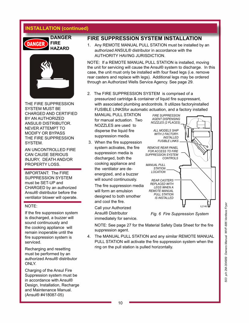
2. The FIRE SUPPRESSION SYSTEM is comprised of a pressurized cartridge & container of liquid fire suppressant, with associated plumbing andcontrols. It utilizes factoryinstalled FUSIBLE LINKSfor automatic actuation, and a factory installed MANUAL PULL STATION for manual actuation. Two NOZZLES are used to disperse the liquid fire suppression media.
3. When the fire suppression system activates, the fire suppression media is discharged, both the cooking appliance and the ventilator are de-energized, and a buzzer will sound continuously.
The fire suppression media will form an emulsion designed to both smother and cool the fire.
Call your Authorized Ansul® Distributor immediately for service.
NOTE: See page 27 for the Material Safety Data Sheet for the fire suppression agent.4. The MANUAL PULL STATION and any similar REMOTE MANUAL
PULL STATION will activate the fire suppression system when the ring on the pull station is pulled horizontally.
DANGER
FIRE HAZARD
THE FIRE SUPPRESSION SYSTEM MUST BE CHARGED AND CERTIFIED BY AN AUTHORIZED ANSUL® DISTRIBUTOR. NEVER ATTEMPT TO MODIFY OR BYPASS THE FIRE SUPPRESSION SYSTEM.AN UNCONTROLLED FIRE CAN CAUSE SERIOUS INJURY, DEATH AND/OR PROPERTY LOSS.
IMPORTANT: The FIRE SUPPRESSION SYSTEM must be SET-UP and CHARGED by an authorized Ansul® distributor before the ventilator blower will operate.
NOTE:If the fire suppression system is discharged, a buzzer will sound continuously and the cooking appliance will remain inoperable until the fire suppression system is serviced.Recharging and resetting must be performed by an authorized Ansul® distributor ONLY.Charging of the Ansul Fire Suppression system must be in accordance with Ansul® Design, Installation, Recharge and Maintenance Manual. (Ansul® #418087-05)
FIRE SUPPRESSIONAGENT DISPENSING
NOZZLES (2 PLACES)
ALL MODELS SHIPWITH 2 FACTORY-
INSTALLED FUSIBLE LINKS
MANUAL PULLSTATION
LOCATION
REAR CASTERSREPLACED WITH
LEGS WHEN AREMOTE MANUAL
PULL STATIONIS INSTALLED
REMOVE REAR PANELFOR ACCESS TO FIRE
SUPPRESSION SYSTEMCONTROLS
IL2146
Fig. 6 Fire Suppression System
10
503
p/n
2M
-304
989
Ow
ners
Man
ual
WV
F-88
6 Ve
ntle
ss F
ryer
503
p/n
2M
-304
989
Ow
ners
Man
ual
WV
F-88
6 Ve
ntle
ss F
ryer
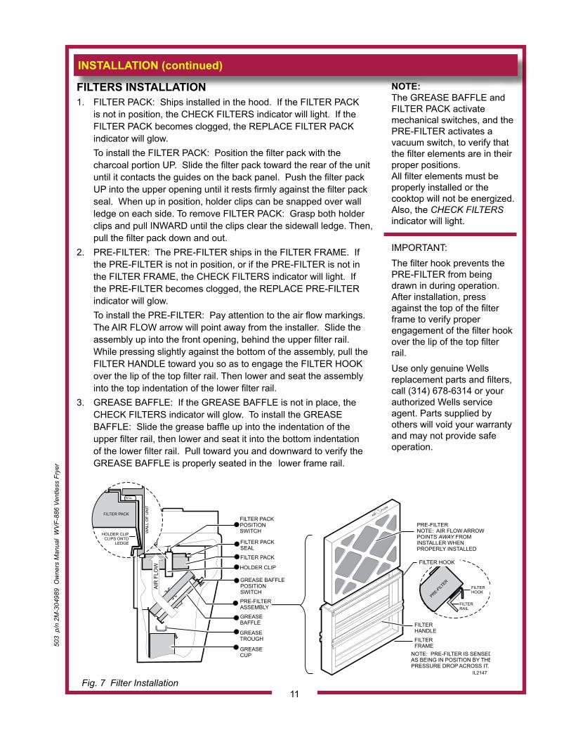
FILTERS INSTALLATION1. FILTER PACK: Ships installed in the hood. If the FILTER PACK
is not in position, the CHECK FILTERS indicator will light. If the FILTER PACK becomes clogged, the REPLACE FILTER PACK indicator will glow.
To install the FILTER PACK: Position the filter pack with the charcoal portion UP. Slide the filter pack toward the rear of the unit until it contacts the guides on the back panel. Push the filter pack UP into the upper opening until it rests firmly against the filter pack seal. When up in position, holder clips can be snapped over wall ledge on each side. To remove FILTER PACK: Grasp both holder clips and pull INWARD until the clips clear the sidewall ledge. Then, pull the filter pack down and out.
2. PRE-FILTER: The PRE-FILTER ships in the FILTER FRAME. If the PRE-FILTER is not in position, or if the PRE-FILTER is not in the FILTER FRAME, the CHECK FILTERS indicator will light. If the PRE-FILTER becomes clogged, the REPLACE PRE-FILTER indicator will glow.
To install the PRE-FILTER: Pay attention to the air flow markings. The AIR FLOW arrow will point away from the installer. Slide the assembly up into the front opening, behind the upper filter rail. While pressing slightly against the bottom of the assembly, pull the FILTER HANDLE toward you so as to engage the FILTER HOOK over the lip of the top filter rail. Then lower and seat the assembly into the top indentation of the lower filter rail.
3. GREASE BAFFLE: If the GREASE BAFFLE is not in place, the CHECK FILTERS indicator will glow. To install the GREASE BAFFLE: Slide the grease baffle up into the indentation of the upper filter rail, then lower and seat it into the bottom indentation of the lower filter rail. Pull toward you and downward to verify the GREASE BAFFLE is properly seated in the lower frame rail.
NOTE: The GREASE BAFFLE and FILTER PACK activatemechanical switches, and the PRE-FILTER activates avacuum switch, to verify that the filter elements are in their proper positions.All filter elements must be properly installed or the cooktop will not be energized. Also, the CHECK FILTERS indicator will light.
IMPORTANT: The filter hook prevents the PRE-FILTER from being drawn in during operation. After installation, press against the top of the filter frame to verify proper engagement of the filter hook over the lip of the top filter rail. Use only genuine Wells replacement parts and filters, call (314) 678-6314 or your authorized Wells service agent. Parts supplied by others will void your warranty and may not provide safe operation.
INSTALLATION (continued)
FILTERRAIL
FILTERHOOK
FILTER PACK
PRE-FILTERASSEMBLY
GREASEBAFFLE
GREASETROUGH
GREASECUP
AIR
FLO
W HOLDER CLIP
FILTER PACKPOSITIONSWITCH
GREASE BAFFLEPOSITIONSWITCH
FILTER PACKSEAL
PRE-FILTERNOTE: AIR FLOW ARROWPOINTS FROMINSTALLER WHEN PROPERLY INSTALLED
AWAY
FILTERFRAME
AIR F
LOW
NOTE: PRE-FILTER IS SENSEDAS BEING IN POSITION BY THEPRESSURE DROP ACROSS IT.
FILTER HOOK
FILTERHANDLE
FILTER PACK
SEAL
HOLDER CLIPCLIPS ONTO
LEDGE
WAL
L O
F U
NIT
PRE-FILT
ER
IL2147
Fig. 7 Filter Installation11
INSTALLATION (continued)
WARNING SLIP / FALL HAZARD SPILLED OIL
DO NOT OPERATE UNLESS THE GREASE CUP
AND TROUGH ARE INSTALLED.
Oil and moisture will drip onto the floor and falls may result. Death or serious injury may result from slipping and falling
On units with optional frypot drains, be sure drain valves are left in the closed position.
GREASE TROUGH AND GREASE CUP INSTALLATION1. Install the GREASE TROUGH into the brackets below the grease
baffle.2. Install the GREASE CUP on the right side of the unit, directly below
the grease trough.
FRYPOT INSTALLATION1. Using the lifting handle, raise the element head. The support rod is
spring loaded and will move into place to support the head.2. Install the frypot in the cutout beneath the element head.3. Lift the element head slightly, then move the element support rod
forward to allow the head to lower.4. Gently lower the element head into the frypot.
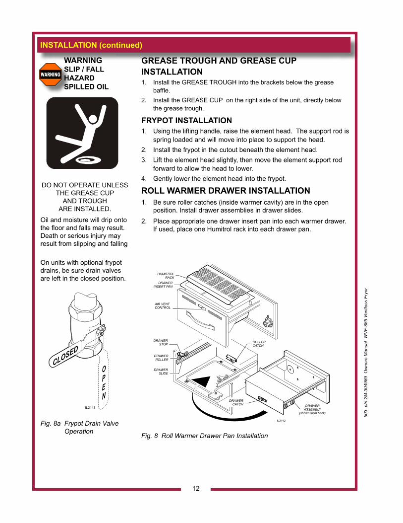
ROLL WARMER DRAWER INSTALLATION1. Be sure roller catches (inside warmer cavity) are in the open
position. Install drawer assemblies in drawer slides.2. Place appropriate one drawer insert pan into each warmer drawer. If used, place one Humitrol rack into each drawer pan.
Fig. 8 Roll Warmer Drawer Pan Installation
12
CLOSED
OPEN
IL2143
Fig. 8a Frypot Drain Valve Operation
IL2142
DRAWERSLIDE
DRAWERSTOP
DRAWERROLLER
ROLLERCATCH
HUMITROLRACK
DRAWERINSERT PAN
AIR VENTCONTROL
DRAWERCATCH DRAWER
ASSEMBLY(shown from back)
503
p/n
2M
-304
989
Ow
ners
Man
ual
WV
F-88
6 Ve
ntle
ss F
ryer
503
p/n
2M
-304
989
Ow
ners
Man
ual
WV
F-88
6 Ve
ntle
ss F
ryer
OPERATION
CAUTION: HOT SURFACE
Exposed surfaces can be hot to the touch and may cause burns.
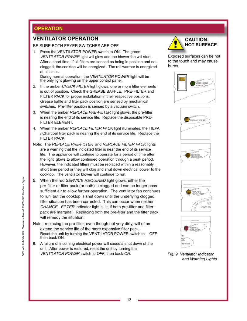
VENTILATOR OPERATIONBE SURE BOTH FRYER SWITCHES ARE OFF.1. Press the VENTILATOR POWER switch to ON. The green
VENTILATOR POWER light will glow and the blower fan will start. After a short time, if all filters are sensed as being in position and not clogged, the cooktop will be energized. The roll warmer is energized at all times.
During normal operation, the VENTILATOR POWER light will be the only light glowing on the upper control panel.
2. If the amber CHECK FILTER light glows, one or more filter elements is out of position. Check the GREASE BAFFLE, PRE-FILTER and FILTER PACK for proper installation in their respective positions. Grease baffle and filter pack position are sensed by mechanical switches. Pre-filter position is sensed by a vacuum switch.
3. When the amber REPLACE PRE-FILTER light glows, the pre-filter is nearing the end of its service life. Replace the disposable PRE-FILTER ELEMENT.
4. When the amber REPLACE FILTER PACK light illuminates, the HEPA / Charcoal filter pack is nearing the end of its service life. Replace the FILTER PACK.
Note: The REPLACE PRE-FILTER and REPLACE FILTER PACK lights are a warning that the indicated filter is near the end of its service life. The appliance will continue to operate for a period of time after the light glows to allow continued operation through a peak period. However, the indicated filters must be replaced within a reasonably short time period or they will clog and shut down electrical power to the cooktop. The ventilator blower will continue to run.
5. When the red SERVICE REQUIRED light glows, either the pre-filter or filter pack (or both) is clogged and can no longer pass sufficient air to allow further operation. The ventilator fan continues to run, but the cooktop is shut down until the underlying clogged filter situation has been corrected. This can occur when neither CHANGE...FILTER indicator light is lit, if both pre-filter and filter pack are marginal. Replacing both the pre-filter and the filter pack will remedy the situation.
Note: replacing the pre-filter, even though not very dirty, will often extend the service life of the more expensive filter pack.
Reset the unit by turning the VENTILATOR POWER switch to OFF, then back ON.
6. A failure of incoming electrical power will cause a shut down of the unit. After power is restored, reset the unit by turning the VENTILATOR POWER switch to OFF, then back ON. Fig. 9 Ventilator Indicator
and Warning Lights
13
OPERATION (continued)
14
FRYER OPERATIONNOTE: The two sections of the fryer are completely separate, and can be used and controlled individually.1. a. Be sure the TEMPERATURE CONTROL KNOB is turned to OFF. b. Lower the element head into the frypot by pulling back on the
ELEMENT LIFTING HANDLE, raising the ELEMENT HEAD SUPPORT ROD, then carefully lowering the elements into the frypot.
2.. IMPORTANT: On units equipped with frypot drains, be sure both drain valves are
closed. IMPORTANT: DO NOT overfill the frypot. Cold oil will expand as it heats. Adding
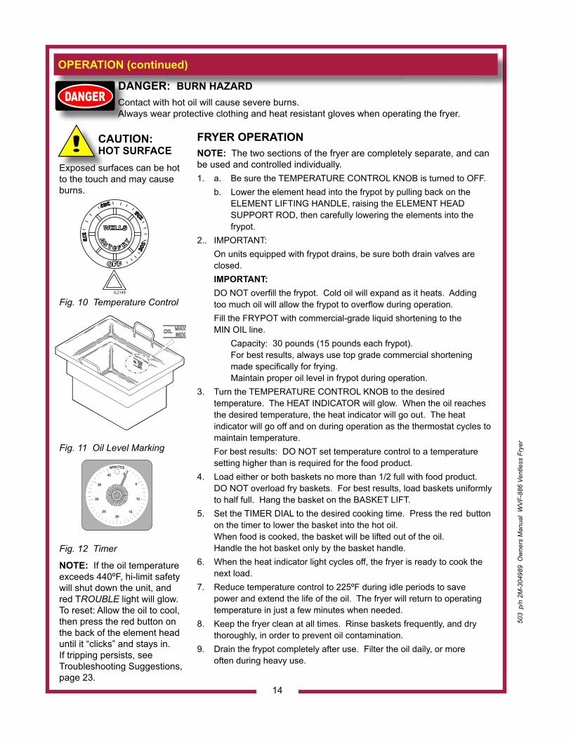
too much oil will allow the frypot to overflow during operation. Fill the FRYPOT with commercial-grade liquid shortening to the
MIN OIL line. Capacity: 30 pounds (15 pounds each frypot).
For best results, always use top grade commercial shortening made specifically for frying. Maintain proper oil level in frypot during operation.
3. Turn the TEMPERATURE CONTROL KNOB to the desired temperature. The HEAT INDICATOR will glow. When the oil reaches the desired temperature, the heat indicator will go out. The heat indicator will go off and on during operation as the thermostat cycles to maintain temperature.
For best results: DO NOT set temperature control to a temperature setting higher than is required for the food product.
4. Load either or both baskets no more than 1/2 full with food product. DO NOT overload fry baskets. For best results, load baskets uniformly to half full. Hang the basket on the BASKET LIFT.
5. Set the TIMER DIAL to the desired cooking time. Press the red button on the timer to lower the basket into the hot oil. When food is cooked, the basket will be lifted out of the oil. Handle the hot basket only by the basket handle.
6. When the heat indicator light cycles off, the fryer is ready to cook the next load.
7. Reduce temperature control to 225ºF during idle periods to save power and extend the life of the oil. The fryer will return to operating temperature in just a few minutes when needed.
8. Keep the fryer clean at all times. Rinse baskets frequently, and dry thoroughly, in order to prevent oil contamination.
9. Drain the frypot completely after use. Filter the oil daily, or more often during heavy use.
DANGER: BURN HAZARDContact with hot oil will cause severe burns.Always wear protective clothing and heat resistant gloves when operating the fryer.
CAUTION: HOT SURFACE
Exposed surfaces can be hot to the touch and may cause burns.
Fig. 10 Temperature Control
Fig. 11 Oil Level Marking
Fig. 12 Timer
NOTE: If the oil temperature exceeds 440ºF, hi-limit safety will shut down the unit, and red TROUBLE light will glow. To reset: Allow the oil to cool, then press the red button on the back of the element head until it “clicks” and stays in.If tripping persists, see Troubleshooting Suggestions, page 23.
OFF
WELLS375
350
325
300
IL2149
503
p/n
2M
-304
989
Ow
ners
Man
ual
WV
F-88
6 Ve
ntle
ss F
ryer
503
p/n
2M
-304
989
Ow
ners
Man
ual
WV
F-88
6 Ve
ntle
ss F
ryer
15
OPERATION (continued)
CAUTION: HOT SURFACE
Exposed surfaces can be hot to the touch and may cause burns.
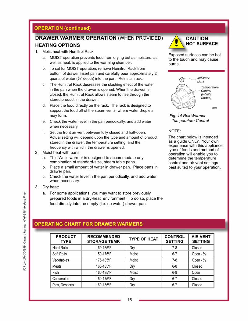
NOTE: The chart below is intended as a guide ONLY. Your own experience with this appliance, type of foods and method of operation will enable you to determine the temperature control and air vent settings best suited to your operation.
DRAWER WARMER OPERATION (WHEN PROVIDED)HEATING OPTIONS1. Moist heat with Humitrol Rack: a. MOIST operation prevents food from drying out as moisture, as
well as heat, is applied to the warming chamber. b. To set for MOIST operation, remove Humitrol Rack from
bottom of drawer insert pan and carefully pour approximately 2 quarts of water (½” depth) into the pan. Reinstall rack.
c. The Humitrol Rack decreases the sloshing effect of the water in the pan when the drawer is opened. When the drawer is closed, the Humitrol Rack allows steam to rise through the stored product in the drawer.
d. Place the food directly on the rack. The rack is designed to support the food off of the steam vents, where water droplets may form.
e. Check the water level in the pan periodically, and add water when necessary.
f. Set the front air vent between fully closed and half-open. Actual setting will depend upon the type and amount of product stored in the drawer, the temperature setting, and the frequency with which the drawer is opened.
2. Moist heat with pans: a. This Wells warmer is designed to accommodate any
combination of standard-size, steam table pans. b. Place a small amount of water in drawer pan. Place pans in
drawer pan. c. Check the water level in the pan periodically, and add water
when necessary.3. Dry heat: a. For some applications, you may want to store previously
prepared foods in a dry-heat environment. To do so, place the food directly into the empty (i.e. no water) drawer pan.
OPERATING CHART FOR DRAWER WARMERS
IndicatorLight
TemperatureControl(InfiniteSwitch)
IL2150
Fig. 14 Roll Warmer Temperature Control
PRODUCT TYPE
RECOMMENDED STORAGE TEMP. TYPE OF HEAT CONTROL
SETTINGAIR VENT SETTING
Hard Rolls 160-185ºF Dry 7-8 Closed Soft Rolls 150-175ºF Moist 6-7 Open - ½ Vegetables 175-185ºF Moist 7-8 Open - ½ Meats 165-185ºF Dry 6-8 Closed Fish 165-185ºF Moist 6-8 Open Casseroles 150-175ºF Dry 6-7 Closed Pies, Desserts 160-185ºF Dry 6-7 Closed
OPERATION (continued)
16
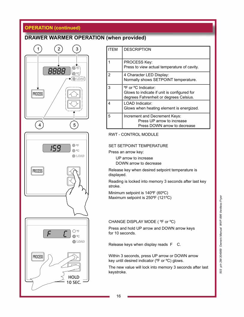
RWT - CONTROL MODULE
SET SETPOINT TEMPERATUREPress an arrow key: UP arrow to increase
DOWN arrow to decreaseRelease key when desired setpoint temperature is displayed.Reading is locked into memory 3 seconds after last key stroke.Minimum setpoint is 140ºF (60ºC) Maximum setpoint is 250ºF (121ºC)
CHANGE DISPLAY MODE ( ºF or ºC)Press and hold UP arrow and DOWN arrow keys for 10 seconds.
Release keys when display reads F C.
Within 3 seconds, press UP arrow or DOWN arrow key until desired indicator (ºF or ºC) glows.The new value will lock into memory 3 seconds after last keystroke.
ITEM DESCRIPTION
1 PROCESS Key:Press to view actual temperature of cavity.
2 4 Character LED Display:Normally shows SETPOINT temperature.
3 ºF or ºC Indicator:Glows to indicate if unit is configured fordegrees Fahrenheit or degrees Celsius.
4 LOAD Indicator:Glows when heating element is energized.
5 Increment and Decrement Keys: Press UP arrow to increase Press DOWN arrow to decrease
DRAWER WARMER OPERATION (when provided)
503
p/n
2M
-304
989
Ow
ners
Man
ual
WV
F-88
6 Ve
ntle
ss F
ryer
503
p/n
2M
-304
989
Ow
ners
Man
ual
WV
F-88
6 Ve
ntle
ss F
ryer
CLEANING INSTRUCTIONS
17
PREPARATION Disconnect appliance from electric power Allow to cool before cleaning
FREQUENCY Weekly
TOOLS Warm water and a mild detergent Soft clean cloth or sponge Bristle brush
ROLL WARMER SECTION1. Disconnect appliance from electric power Allow to cool before cleaning2. Remove roll warmer drawers, drawer inserts and Humitrol racks. 3. Brush crumbs from drawer slides and interior of warmer cavity with
a bristle brush.4. Wash and rinse the drawer inserts and Humitrol racks in a sink or
dishwasher using mild detergent and warm water. Allow to air dry.5. Reassemble and reinstall warmer drawers.
Procedure is complete
CAUTION: ELECTRIC SHOCK HAZARD
Disconnect appliance from electric power before cleaning.
CAUTION: HOT SURFACE
Exposed surfaces can be hot to the touch and may cause burns. Allow appliance to cool before cleaning.
IMPORTANT:DO NOT spill or pour water into controls, control panel, wiring. Damage to internal components will occur.Damage to internalcomponents from waterdamage is not covered bywarranty.
IMPORTANT:DO NOT use steel wool or metal implements to clean drawers or cabinet surfaces.
CLEANING INSTRUCTIONS (continued)
CAUTION: ELECTRIC SHOCK HAZARD
Disconnect appliance from electric power before cleaning.
CAUTION: HOT SURFACE
Exposed surfaces can be hot to the touch and may cause burns. Allow appliance to cool before cleaning.
IMPORTANT:Never allow PRE-FILTER or FILTER PACK to get wet. DO NOT wash either of these two filters. Washing these filters will ruin them and cause the appliance to shut-down.
IMPORTANT:DO NOT spill or pour water into controls, control panel, wiring or coil-type hotplate elements. Damage to internal components will occur.Damage to internalcomponents from waterdamage is not covered bywarranty.
IMPORTANT:DO NOT use steel wool or metal implements to clean cabinet surfaces.
VENTILATOR WEEKLY CLEANING
PREPARATION: Disconnect appliance from electric power Allow to cool before cleaning
FREQUENCY: Weekly
TOOLS: Warm water and a mild detergent Soft clean cloth or sponge Bristle brush Container for disposal of grease
1. Disconnect appliance from electric power Allow to cool before cleaning2. Remove the grease baffle, pre-filter assembly, grease trough and
grease cup. Empty the grease trough and grease cup.
3. IMPORTANT: Never allow PRE-FILTER or FILTER PACK to get wet. DO NOT wash either of these two filters. Washing these filters will
ruin them and cause the appliance to shut-down. Remove the pre-filter from the filter frame.
Wash and rinse the filter frame ONLY.4. Wash and rinse the grease baffle, grease trough and grease cup in
a sink or dishwasher using mild detergent and warm water. Allow to air dry.
5. Reinsert the pre-filter into the filter frame. Reinstall the pre-filter, grease baffle, grease trough and grease cup.
Procedure is complete
18
503
p/n
2M
-304
989
Ow
ners
Man
ual
WV
F-88
6 Ve
ntle
ss F
ryer
503
p/n
2M
-304
989
Ow
ners
Man
ual
WV
F-88
6 Ve
ntle
ss F
ryer
CLEANING INSTRUCTIONS (continued)
19
CAUTION:ELECTRIC SHOCK HAZARD
Disconnect appliance from electric power before cleaning.
CAUTION: HOT SURFACE
Exposed surfaces can be hot to the touch and may cause burns. Allow appliance to cool before cleaning.
IMPORTANT:Never allow PRE-FILTER or FILTER PACK to get wet. DO NOT wash either of these two filters. Washing these filters will ruin them and cause the appliance to shut-down.
IMPORTANT:DO NOT spill or pour water into controls, control panel, wiring or coil-type hotplate elements. Damage to internal components will occur.Damage to internal components from water damage is not covered by warranty.
IMPORTANT:DO NOT use steel wool or metal implements to clean cabinet surfaces.
VENTILATOR MONTHLY CLEANING
PREPARATION: Disconnect appliance from electric power Allow to cool before cleaning
FREQUENCY: Monthly
TOOLS: Warm water and a mild detergent Soft clean cloth or sponge Plastic scouring pad, plastic scraper Container for disposal of grease
EXTERIOR Wash exterior surfaces with a soft clean cloth or sponge dampened
with warm water, mild soap or detergent. Rinse with a soft clean cloth or sponge dampened with warm water. Allow to air dry.
INTERIOR: In addition to the weekly cleaning procedure, remove the filter
pack.
Cover the griddle section. Wash the interior surfaces of the ventilator with warm water, mild soap or detergent and a clean, soft cloth or sponge. Stubborn or burned-on food debris bay be removed with a plastic scouring pad or plastic scraper.
Dry thoroughly with a clean soft cloth.
Uncover the griddle and reassemble the ventilator.
Procedure is complete.
CLEANING INSTRUCTIONS
20
DANGER: BURN HAZARDContact with hot oil will cause severe burns. Allow the fryer to cool before cleaning.Always wear protective clothing and heat resistant gloves when cleaning the fryer.
PREPARATION Turn temperature control to OFF Allow fryer to cool completely before cleaning Disconnect fryer from electric power before
cleaning
FREQUENCY Daily, or as needed
TOOLS Mild Detergent, Non-abrasive cleanser Soft Cloth or Sponge, Plastic Scouring Pad Container for disposal of used oil.
FRYER SECTION - UNITS WITHOUT DRAIN
1. Turn temperature control to OFF. Disconnect from electric power.2. Remove fry baskets, then swing the element heads up and out of
the frypots. NOTE: The element support rod is spring-loaded. When the
element head is raised, the support rod will automatically swing into position to keep the element head raised.
3. Allow the oil to cool to a safe temperature (120ºF or less). Carefully remove the frypots: wearing heat-resistant gloves, lift the frypots by the handles. Drain the oil into a suitable container.
4. Frypots and baskets may be washed in a dishwasher, or with warm water and mild detergent. Rinse thoroughly and dry completely.
5. Wipe/brush all crumbs, breading and cooking debris from the elements. Pay particular attention to the area between the element and the thermobulbs. Be careful that the capillary tubes of the thermobulbs are not moved or damaged during cleaning.
6. Keep all exterior surfaces free from splashed grease by wiping with a clean cloth dampened with warm water and mild detergent. A non-abrasive detergent and plastic scouring pad may be used for stubborn deposits.
IMPORTANT: DO NOT use steel wool or abrasive cleansers as these will damage the surface finish.
IMPORTANT: DO NOT spill or pour water into controls, control panel or wiring. Damage to internal components will occur.
7. Be certain frypots are completely dry, then reinstall in fryer. a. Be sure the TEMPERATURE CONTROL KNOB is turned to
OFF, then plug unit into receptacle. b. Lower the element headS into the frypot by pushing back
on the ELEMENT LIFTING HANDLE, raising the SUPPORT ROD, then carefully lowering the elements.
c. Add new or filtered oil to the MIN OIL line in frypots.Procedure is complete.
CAUTION:ELECTRIC SHOCK HAZARD
Disconnect fryer from electric power before cleaning.
CAUTION: BURN HAZARD
Allow fryer to cool completely before cleaning.
IMPORTANT: Nickel plated frypot must be dried completely in order to prevent rusting, and to eliminate water contamination of the cooking oil.
To remove carbonization from elements and frypot, see PERIODIC CLEANING, page 23.
503
p/n
2M
-304
989
Ow
ners
Man
ual
WV
F-88
6 Ve
ntle
ss F
ryer
503
p/n
2M
-304
989
Ow
ners
Man
ual
WV
F-88
6 Ve
ntle
ss F
ryer
CLEANING INSTRUCTIONS (continued)
21
PREPARATION Turn temperature control to OFF Allow fryer to cool completely before cleaning Disconnect fryer from electric power before
cleaning
FREQUENCY Daily, or as needed
TOOLS Mild Detergent, Non-abrasive cleanser Soft Cloth or Sponge, Plastic Scouring Pad Container for disposal of used oil.
FRYER SECTION - UNITS WITH OPTIONAL DRAIN
1. Turn temperature control to OFF. Disconnect from electric power.2. Remove fry baskets, then swing the element heads up and out of
the frypots.NOTE: The element support rod is spring-loaded. When the element
head is raised, the support rod will automatically swing into position to keep the element head raised.
3. Allow the oil to cool to a safe temperature (120ºF or less). Place suitable container under the drain and open valve. Drain the oil into the container.
4. Frypots must be cleaned in place with warm water and mild detergent. Rinse thoroughly and dry completely.
5. Baskets may be washed in a dishwasher, or with warm water and mild detergent. Rinse thoroughly and dry completely.
6. Wipe/brush all crumbs, breading and cooking debris from then elements. Pay particular attention to the area between the element and the thermobulbs. Be careful that the capillary tubes of the thermobulbs are not moved or damaged during cleaning.
7. Keep all exterior surfaces free from splashed grease by wiping with a clean cloth dampened with warm water and mild detergent. A non-abrasive detergent and plastic scouring pad may be used for stubborn deposits.
IMPORTANT: DO NOT use steel wool or abrasive cleansers as these will damage the surface finish.
IMPORTANT: DO NOT spill or pour water into controls, control panel or wiring. Damage to internal components will occur.
8. Be certain frypot drain valves are closed. a. Be sure the TEMPERATURE CONTROL KNOB is turned to OFF,
then plug unit into receptacle. b. Lower the ELEMENT HEADS into the frypot by pushing back on
the ELEMENT LIFTING HANDLE, raising the SUPPORT ROD, then carefully lowering the elements.
c. Add new or filtered oil to the MIN OIL line in frypots.Procedure is complete.
DANGER: BURN HAZARDContact with hot oil will cause severe burns. Allow the fryer to cool before cleaning.Always wear protective clothing and heat resistant gloves when cleaning the fryer.
CAUTION:ELECTRIC SHOCK HAZARD
Disconnect fryer from electric power before cleaning.
CAUTION: BURN HAZARD
Allow fryer to cool completely before cleaning.
IMPORTANT: Nickel plated frypot must be dried completely in order to prevent rusting, and to eliminate water contamination of the cooking oil.
To remove carbonization from elements and frypot, see PERIODIC CLEANING, page 23.
22
DISPOSAL OF USED OIL
DANGER: BURN HAZARDContact with hot oil will cause severe burns. Allow the fryer to cool before cleaning.Always wear protective clothing and heat resistant gloves when handling hot oil.
PREPARATION Turn temperature control to OFF Allow fryer to cool completely before draining
FREQUENCY Daily, or as needed
TOOLS Container for disposal of used oil.
OIL DISPOSAL
1. Turn temperature control to OFF.
2. Allow the oil to cool to a safe temperature (120ºF or 50ºC). 3. UNITS WITHOUT DRAIN:
Carefully remove the frypots: wearing heat-resistant gloves, raise the element head and lift the frypot out of the fryer by the frypot handles. Drain the oil into a suitable container. Wipe the frypot and reinstall in the fryer
UNITS WITH OPTIONAL DRAIN: Place a suitable container under the drain valve. Wearing heat- resistant gloves, open the drain valve and drain the oil into the container. Close the drain valve after all oil is drained.
4. Dispose of the used oil in an approved oil disposal receptacle, or filter the oil for reuse.
Procedure is complete.
CAUTION: BURN HAZARD
Allow fryer to cool completely before draining.
CAUTION:SLIP / FALLHAZARD
Clean up oil spills immediately. Slipping in oil can cause injury.
CAUTION:HEALTHHAZARD
Clean up spills immediately. Oil provides an environment for the growth of bacteria, which presents a health hazard.
503
p/n
2M
-304
989
Ow
ners
Man
ual
WV
F-88
6 Ve
ntle
ss F
ryer
503
p/n
2M
-304
989
Ow
ners
Man
ual
WV
F-88
6 Ve
ntle
ss F
ryer
23
MAINTENANCE
CAUTIONBURN HAZARD
This procedure involves very hot liquids. Wear protective clothing and heat-resistant gloves.
Periodic cleaning is necessary to remove carbonization from the elements and frypot.
Frypot may be cleaned by the method described at right, or with a commercial frypot cleaner. Be sure to follow the manufacturer’s directions.
Before cleaning, ALWAYS: • Disconnect the fryer
from electric power and allow to cool.
• Drain the oil and wipe out the frypot.
PERIODIC CLEANING
1. Add 1/2 cup of granulated dishwasher detergent to frypot. Fill with water to the MAX OIL line.
2. Lower the element into the frypot and set the control knob to 225ºF
3. Boil the mixture for five minutes. Turn the control knob to OFF.
Allow the mixture to set in the frypot overnight.
4. After the soak period, raise the elements and remove any remaining carbonization with a stiff bristle brush.
IMPORTANT: Be careful that the capillary tubes of the thermobulbs are not moved or damaged during cleaning.
5. Drain the frypot and wash with warm water and mild detergent. Rinse with clean water.
6. Reinstall the frypot in the fryer (frypots without drain), or close drain valve (frypots with optional drain).
Add 1 quart of vinegar, then fill to the MAX OIL line with cold water.
Lower the elements into the vinegar solution.
Allow to set for 15 minutes.
7. Drain the frypot and rinse with clean water. Dry the frypot and elements thoroughly before returning the fryer to operation.
IMPORTANT: Nickel plated frypot must be dried completely in order to prevent rusting, and to eliminate water contamination of the cooking oil.
Procedure is complete.
DANGER: BURN HAZARDContact with hot oil will cause severe burns. Allow the fryer to cool draining oil.Always wear protective clothing and heat resistant gloves when handling hot oil.
TROUBLESHOOTING SUGGESTIONS
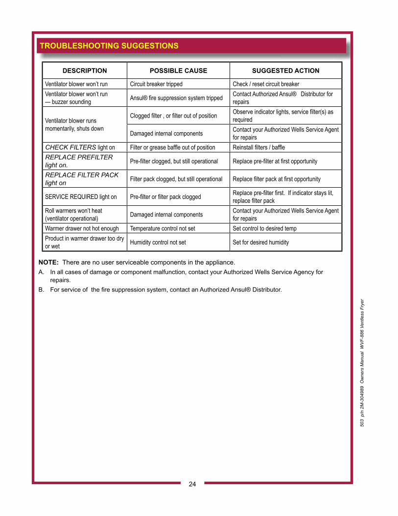
NOTE: There are no user serviceable components in the appliance.A. In all cases of damage or component malfunction, contact your Authorized Wells Service Agency for
repairs.B. For service of the fire suppression system, contact an Authorized Ansul® Distributor.
24
503
p/n
2M
-304
989
Ow
ners
Man
ual
WV
F-88
6 Ve
ntle
ss F
ryer
DESCRIPTION POSSIBLE CAUSE SUGGESTED ACTION
Ventilator blower won’t run Circuit breaker tripped Check / reset circuit breakerVentilator blower won’t run — buzzer sounding Ansul® fire suppression system tripped Contact Authorized Ansul® Distributor for
repairs
Ventilator blower runs momentarily, shuts down
Clogged filter , or filter out of position Observe indicator lights, service filter(s) as required
Damaged internal components Contact your Authorized Wells Service Agent for repairs
CHECK FILTERS light on Filter or grease baffle out of position Reinstall filters / baffleREPLACE PREFILTER light on. Pre-filter clogged, but still operational Replace pre-filter at first opportunity
REPLACE FILTER PACK light on Filter pack clogged, but still operational Replace filter pack at first opportunity
SERVICE REQUIRED light on Pre-filter or filter pack clogged Replace pre-filter first. If indicator stays lit, replace filter pack
Roll warmers won’t heat (ventilator operational) Damaged internal components Contact your Authorized Wells Service Agent
for repairsWarmer drawer not hot enough Temperature control not set Set control to desired tempProduct in warmer drawer too dry or wet Humidity control not set Set for desired humidity
503
p/n
2M
-304
989
Ow
ners
Man
ual
WV
F-88
6 Ve
ntle
ss F
ryer
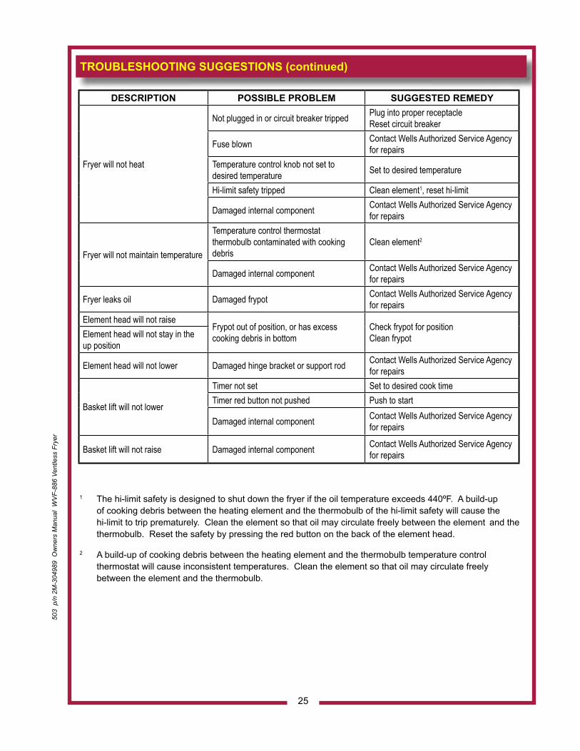
1 The hi-limit safety is designed to shut down the fryer if the oil temperature exceeds 440ºF. A build-up of cooking debris between the heating element and the thermobulb of the hi-limit safety will cause the hi-limit to trip prematurely. Clean the element so that oil may circulate freely between the element and the thermobulb. Reset the safety by pressing the red button on the back of the element head.
2 A build-up of cooking debris between the heating element and the thermobulb temperature control thermostat will cause inconsistent temperatures. Clean the element so that oil may circulate freely between the element and the thermobulb.
TROUBLESHOOTING SUGGESTIONS (continued)
25
DESCRIPTION POSSIBLE PROBLEM SUGGESTED REMEDY
Fryer will not heat
Not plugged in or circuit breaker tripped Plug into proper receptacle Reset circuit breaker
Fuse blown Contact Wells Authorized Service Agency for repairs
Temperature control knob not set to desired temperature Set to desired temperature
Hi-limit safety tripped Clean element1, reset hi-limit
Damaged internal component Contact Wells Authorized Service Agency for repairs
Fryer will not maintain temperature
Temperature control thermostat thermobulb contaminated with cooking debris
Clean element2
Damaged internal component Contact Wells Authorized Service Agency for repairs
Fryer leaks oil Damaged frypot Contact Wells Authorized Service Agency for repairs
Element head will not raiseFrypot out of position, or has excess cooking debris in bottom
Check frypot for position Clean frypotElement head will not stay in the
up position
Element head will not lower Damaged hinge bracket or support rod Contact Wells Authorized Service Agency for repairs
Basket lift will not lower
Timer not set Set to desired cook timeTimer red button not pushed Push to start
Damaged internal component Contact Wells Authorized Service Agency for repairs
Basket lift will not raise Damaged internal component Contact Wells Authorized Service Agency for repairs
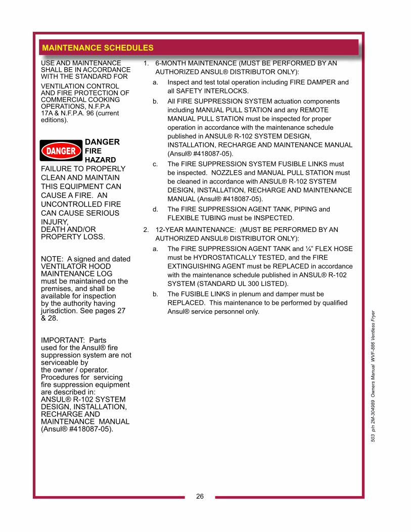
MAINTENANCE SCHEDULES
USE AND MAINTENANCE SHALL BE IN ACCORDANCE WITH THE STANDARD FOR VENTILATION CONTROL AND FIRE PROTECTION OF COMMERCIAL COOKING OPERATIONS, N.F.P.A 17A & N.F.P.A. 96 (current editions).
DANGER FIRE HAZARD
FAILURE TO PROPERLY CLEAN AND MAINTAIN THIS EQUIPMENT CANCAUSE A FIRE. AN UNCONTROLLED FIRE CAN CAUSE SERIOUS INJURY, DEATH AND/OR PROPERTY LOSS.
NOTE: A signed and dated VENTILATOR HOOD MAINTENANCE LOG must be maintained on the premises, and shall be available for inspection by the authority having jurisdiction. See pages 27 & 28.
IMPORTANT: Parts used for the Ansul® fire suppression system are not serviceable by the owner / operator. Procedures for servicing fire suppression equipment are described in:ANSUL® R-102 SYSTEM DESIGN, INSTALLATION, RECHARGE AND MAINTENANCE MANUAL (Ansul® #418087-05).
1. 6-MONTH MAINTENANCE (MUST BE PERFORMED BY AN AUTHORIZED ANSUL® DISTRIBUTOR ONLY):
a. Inspect and test total operation including FIRE DAMPER and all SAFETY INTERLOCKS.
b. All FIRE SUPPRESSION SYSTEM actuation components including MANUAL PULL STATION and any REMOTE MANUAL PULL STATION must be inspected for proper operation in accordance with the maintenance schedule published in ANSUL® R-102 SYSTEM DESIGN, INSTALLATION, RECHARGE AND MAINTENANCE MANUAL (Ansul® #418087-05).
c. The FIRE SUPPRESSION SYSTEM FUSIBLE LINKS must be inspected. NOZZLES and MANUAL PULL STATION must be cleaned in accordance with ANSUL® R-102 SYSTEM DESIGN, INSTALLATION, RECHARGE AND MAINTENANCE MANUAL (Ansul® #418087-05).
d. The FIRE SUPPRESSION AGENT TANK, PIPING and FLEXIBLE TUBING must be INSPECTED.
2. 12-YEAR MAINTENANCE: (MUST BE PERFORMED BY AN AUTHORIZED ANSUL® DISTRIBUTOR ONLY):
a. The FIRE SUPPRESSION AGENT TANK and ¼” FLEX HOSE must be HYDROSTATICALLY TESTED, and the FIRE EXTINGUISHING AGENT must be REPLACED in accordance with the maintenance schedule published in ANSUL® R-102 SYSTEM (STANDARD UL 300 LISTED).
b. The FUSIBLE LINKS in plenum and damper must be REPLACED. This maintenance to be performed by qualified Ansul® service personnel only.
26
503
p/n
2M
-304
989
Ow
ners
Man
ual
WV
F-88
6 Ve
ntle
ss F
ryer
503
p/n
2M
-304
989
Ow
ners
Man
ual
WV
F-88
6 Ve
ntle
ss F
ryer
27
WEL
LS B
LOO
MFI
ELD
, LLC IL
2144
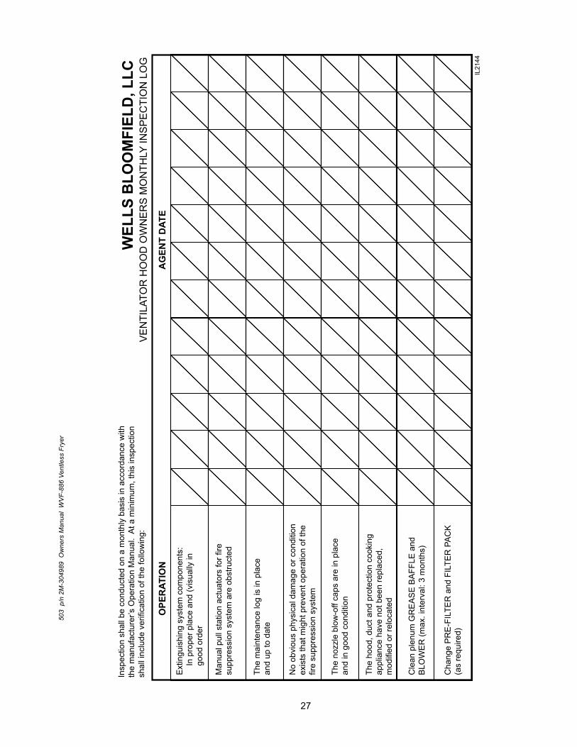
Insp
ectio
n sh
all b
e co
nduc
ted
on a
mon
thly
bas
is in
acc
orda
nce
with
the
man
ufac
ture
r’s O
pera
tion
Man
ual.
At a
min
imum
, thi
s in
spec
tion
shal
l inc
lude
ver
ifica
tion
of th
e fo
llow
ing:
OPE
RAT
ION
AG
ENT
DAT
E
Ext
ingu
ishi
ng s
yste
m c
ompo
nent
s:
In p
rope
r pla
ce a
nd (v
isua
lly in
g
ood
orde
r
Man
ual p
ull s
tatio
n ac
tuat
ors
for f
iresu
ppre
ssio
n sy
stem
are
obs
truct
ed
The
mai
nten
ance
log
is in
pla
cean
d up
to d
ate
The
nozz
le b
low
-off
caps
are
in p
lace
and
in g
ood
cond
ition
The
hood
, duc
t and
pro
tect
ion
cook
ing
appl
ianc
e ha
ve n
ot b
een
repl
aced
,m
odifi
ed o
r rel
ocat
ed
Cle
an p
lenu
m G
RE
AS
E B
AFF
LE a
ndB
LOW
ER
(max
. int
erva
l: 3
mon
ths)
Cha
nge
PR
E-F
ILTE
R a
nd F
ILTE
R P
AC
K
(as
requ
ired)
No
obvi
ous
phys
ical
dam
age
or c
ondi
tion
exis
ts th
at m
ight
pre
vent
ope
ratio
n of
the
fire
supp
ress
ion
syst
em
VE
NTI
LATO
R H
OO
D O
WN
ER
S M
ON
THLY
INS
PE
CTI
ON
LO
G
28
503
p/n
2M
-304
989
Ow
ners
Man
ual
WV
F-88
6 Ve
ntle
ss F
ryer
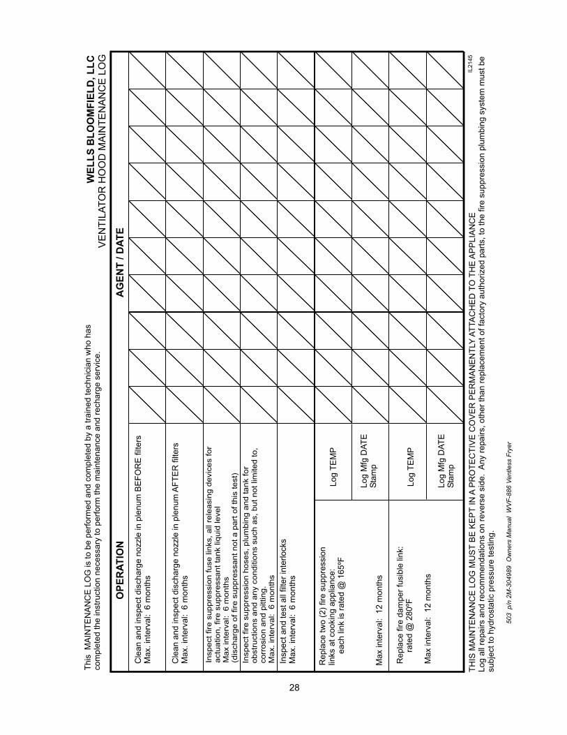
Rep
lace
two
(2) f
ire s
uppr
essi
onlin
ks a
t coo
king
app
lianc
e:
eac
h lin
k is
rate
d @
165
ºF
WEL
LS B
LOO
MFI
ELD
, LLC
Rep
lace
fire
dam
per f
usib
le li
nk:
r
ated
@ 2
80ºF
Max
inte
rval
: 12
mon
ths
IL21
45
29
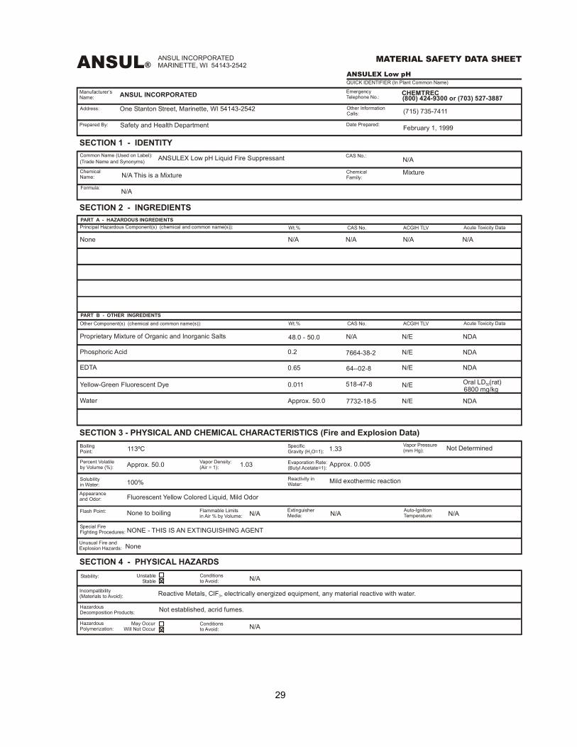
ANSUL®ANSUL INCORPORATEDMARINETTE, WI 54143-2542
MATERIAL SAFETY DATA SHEET
ANSULEX Low pHQUICK IDENTIFIER (In Plant Common Name)
Manufacturer’sName:
EmergencyTelephone No.:ANSUL INCORPORATED CHEMTREC
(800) 424-9300 or (703) 527-3887
Prepared By:
Address: One Stanton Street, Marinette, WI 54143-2542
Safety and Health Department
Other InformationCalls: (715) 735-7411
Date Prepared: February 1, 1999
SECTION 1 - IDENTITY
SECTION 2 - INGREDIENTS
SECTION 3 - PHYSICAL AND CHEMICAL CHARACTERISTICS (Fire and Explosion Data)
SECTION 4 - PHYSICAL HAZARDS
Common Name (Used on Label):(Trade Name and Synonyms) ANSULEX Low pH Liquid Fire Suppressant CAS No.:
N/A
N/A N/A N/A N/A
N/A
N/A
N/A
N/A
N/A N/A
N/E
N/E
N/E
N/E
N/E
NDA
NDA
NDA
NDA
N/A
ChemicalName: N/A This is a Mixture Chemical
Family:Mixture
Formula:
PART A - HAZARDOUS INGREDIENTS
PART B - OTHER INGREDIENTS
Principal Hazardous Component(s) (chemical and common name(s)):
Other Component(s) (chemical and common name(s)):
Wt.%
Wt.%
CAS No.
CAS No.
ACGIH TLV
ACGIH TLV
Acute Toxicity Data
Acute Toxicity Data
None
Proprietary Mixture of Organic and Inorganic Salts 48.0 - 50.0
Phosphoric Acid 0.2 7664-38-2
Yellow-Green Fluorescent Dye 0.011 518-47-8 Oral LD (rat)50
6800 mg/kg
EDTA 0.65 64--02-8
Water Approx. 50.0 7732-18-5
BoilingPoint:
Percent Volatileby Volume (%):
Solubilityin Water:
Appearanceand Odor:
Flash Point:
Special FireFighting Procedures:
Unusual Fire andExplosion Hazards:
113ºC
Approx. 50.0
100%
Fluorescent Yellow Colored Liquid, Mild Odor
None to boiling
NONE - THIS IS AN EXTINGUISHING AGENT
None
Vapor Density:(Air = 1):
Flammable Limitsin Air % by Volume:
1.03
SpecificGravity (H O=1):2
Vapor Pressure(mm Hg):1.33 Not Determined
Evaporation Rate:(Butyl Acetate=1): Approx. 0.005
Reactivity inWater: Mild exothermic reaction
ExtinguisherMedia:
Auto-IgnitionTemperature:
Stability:
Incompatibility(Materials to Avoid):
HazardousDecomposition Products:
HazardousPolymerization:
UnstableStable
Conditionsto Avoid:
Conditionsto Avoid:
Reactive Metals, ClF , electrically energized equipment, any material reactive with water.3
Not established, acrid fumes.
May OccurWill Not Occur
30
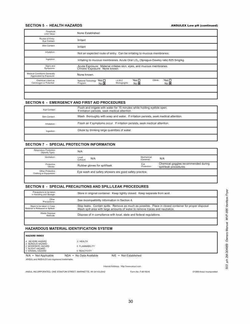
SECTION 5 - HEALTH HAZARDS
SECTION 6 - EMERGENCY AND FIRST AID PROCEDURES
SECTION 7 - SPECIAL PROTECTION INFORMATION
SECTION 8 - SPECIAL PRECAUTIONS AND SPILL/LEAK PROCEDURES
HAZARDOUS MATERIAL IDENTIFICATION SYSTEM
ANSULEX Low pH (continued)
ThresholdLimit Value: None Established
Routes of Entry:Eye Contact: Irritant
IrritantSkin Contact:
Skin Contact:
Inhalation:
Inhalation:
Not an expected route of entry. Can be irritating to mucous membranes.
Irritating to mucous membranes. Acute Oral LD (Sprague-Dawley rats) 825.5mg/kg.50Ingestion:
Ingestion:
Signs andSymptoms:
Acute Exposure: Material irritates skin, eyes, and mucous membranes.Chronic Exposure: None known.
Medical Conditions GenerallyAggravated by Exposure: None known.
Chemical Listed asCarcinogen or Potential:
YesNo
YesNo
YesNo
National ToxicologyProgram:
I.A.R.CMonographs:
OSHA
Eye Contact:Flush and irrigate with water for 15 minutes while holding eyelids open.If irritation persists, seek medical attention.
Wash thoroughly with soap and water. If irritation persists, seek medical attention.
Fresh air if symptoms occur. If irritation persists, seek medical attention.
Dilute by drinking large quantities of water.
Respiratory Protection(Specify Type): N/A
N/A N/AVentilation: LocalExhaust:
Mechanical(General):
ProtectiveGloves: Rubber gloves for spill/leak Eye
Protection:Chemical goggles recommended duringspill/leak procedures.
Other ProtectiveClothing or Equipment: Eye wash and safety showers are good safety practice.
Precautions to be takenin Handling and Storage:
OtherPrecautions:
Steps to be taken in CaseMaterial is Released or Spilled:
Waste DisposalMethods:
Store in original container. Keep tightly closed. Keep separate from acid.
See incompatibility information in Section 4.
Stop leaks. Contain spills. Remove as much as possible. Place in closed container for proper disposalWash spill area with large amounts of water to remove traces and neutralize.
Dispose of in compliance with local, state and federal regulations.
HAZARD INDEX
4 SEVERE HAZARD 0 HEALTH3 SERIOUS HAZARD2 MODERATE HAZARD 0 FLAMMABILITY1 SLIGHT HAZARD0 MINIMAL HAZARD 0 REACTIVITY
N/A = Not Applicable NDA = No Data Available N/E = Not EstablishedANSUL and ANSULEX are registered trademarks.
Internet Address: http://www.ansul.com
ANSUL INCORPORATED, ONE STANTON STREET, MARINETTE, WI 54143-2542 Form No. F-90160-6 ©1999 Ansul Incorporated
503
p/n
2M
-304
989
Ow
ners
Man
ual
WV
F-88
6 Ve
ntle
ss F
ryer
31
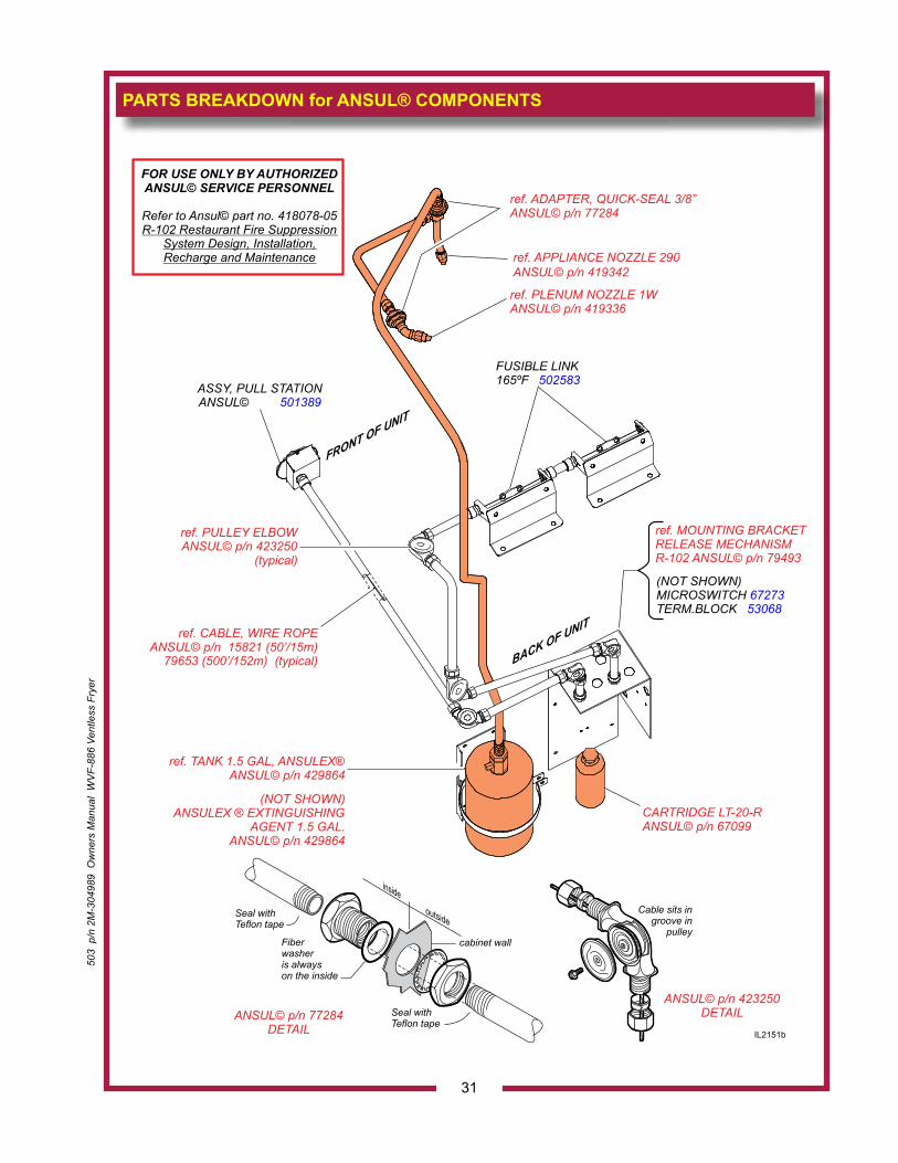
PARTS BREAKDOWN for ANSUL® COMPONENTS
ANSUL© p/n 77284DETAIL
inside
outside
cabinet wall
Seal withTeflon tape
Seal withTeflon tape
Fiberwasheris alwayson the inside
ANSUL© p/n 423250DETAIL
Cable sits ingroove in
pulley
ref. PLENUM NOZZLE 1WANSUL© p/n 419336
ref. APPLIANCE NOZZLE 290ANSUL© p/n 419342
ref. ADAPTER, QUICK-SEAL 3/8”ANSUL© p/n 77284
FUSIBLE LINK165ºF 502583
ref. PULLEY ELBOWANSUL© p/n 423250
(typical)
ref. MOUNTING BRACKETRELEASE MECHANISMR-102 ANSUL© p/n 79493
ASSY, PULL STATIONANSUL© 501389
CARTRIDGE LT-20-RANSUL© p/n 67099
ref. CABLE, WIRE ROPEANSUL© p/n 15821 (50’/15m)
79653 (500’/152m) (typical)
ref. TANK 1.5 GAL, ANSULEX®ANSUL© p/n 429864
(NOT SHOWN)ANSULEX ® EXTINGUISHING
AGENT 1.5 GAL.ANSUL© p/n 429864
(NOT SHOWN)MICROSWITCH 67273TERM.BLOCK 53068
FRONT OF UNIT
BACK OF UNIT
FOR USE ONLY BY AUTHORIZEDANSUL© SERVICE PERSONNEL
Refer to Ansul© part no. 418078-05R-102 Restaurant Fire Suppression
System Design, Installation,Recharge and Maintenance
IL2151b
503
p/n
2M
-304
989
Ow
ners
Man
ual
WV
F-88
6 Ve
ntle
ss F
ryer
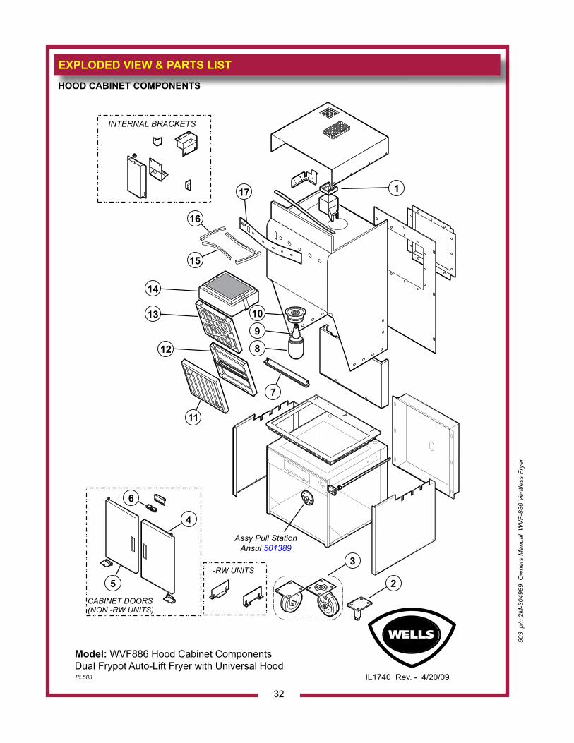
EXPLODED VIEW & PARTS LIST
32
503
p/n
2M
-304
989
Ow
ners
Man
ual
WV
F-88
6 Ve
ntle
ss F
ryer
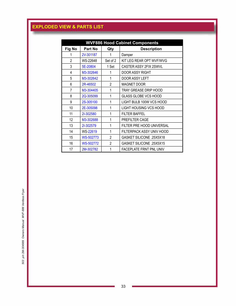
HOOD CABINET COMPONENTS
Model: WVF886 Hood Cabinet Components Dual Frypot Auto-Lift Fryer with Universal HoodPL503 IL1740 Rev. - 4/20/09
INTERNAL BRACKETS
CABINET DOORS(NON -RW UNITS)
-RW UNITS
1
2
3
4
6
5
7
11
Assy Pull StationAnsul 501389
12
13
14
15
16
17
8
9
10
503
p/n
2M
-304
989
Ow
ners
Man
ual
WV
F-88
6 Ve
ntle
ss F
ryer
EXPLODED VIEW & PARTS LIST
33
WVF886 Hood Cabinet ComponentsFig No Part No Qty Description
1 2V-301187 1 Damper2 WS-22648 Set of 2 KIT LEG REAR OPT WVF/WVG3 5E-20804 1 Set CASTER ASSY 2FIX 2SWVL4 M3-302646 1 DOOR ASSY RIGHT5 M3-302642 1 DOOR ASSY LEFT6 2R-46502 2 MAGNET DOOR7 M3-304405 1 TRAY GREASE DRIP HOOD8 2Q-305099 1 GLASS GLOBE VCS HOOD9 2S-305100 1 LIGHT BULB 100W VCS HOOD10 2E-305098 1 LIGHT HOUSING VCS HOOD11 2I-302580 1 FILTER BAFFEL12 M3-302688 1 PREFILTER CAGE13 2I-302579 1 FILTER PRE HOOD UNIVERSAL14 WS-22619 1 FILTERPACK ASSY UNIV HOOD15 WS-502773 2 GASKET SILICONE .25X5X1816 WS-502772 2 GASKET SILICONE .25X5X1517 2M-302782 1 FACEPLATE FRNT PNL UNIV
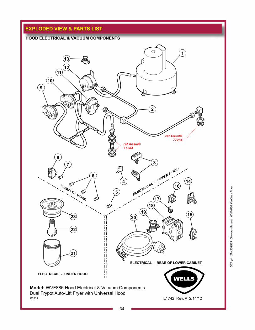
EXPLODED VIEW & PARTS LIST
34
HOOD ELECTRICAL & VACUUM COMPONENTS
Model: WVF886 Hood Electrical & Vacuum Components Dual Frypot Auto-Lift Fryer with Universal HoodPL503 IL1742 Rev. A 2/14/12
FRONT OF HOODELECTRICAL -
UPPER HOOD
ELECTRICAL - UNDER HOOD
ELECTRICAL - REAR OF LOWER CABINET
ref Ansul®77284
ref Ansul®77284
1
2
4
5
21
22
23
14
15
16
1718
1920
78
910
1112
13
3
6
503
p/n
2M
-304
989
Ow
ners
Man
ual
WV
F-88
6 Ve
ntle
ss F
ryer

503
p/n
2M
-304
989
Ow
ners
Man
ual
WV
F-88
6 Ve
ntle
ss F
ryer
EXPLODED VIEW & PARTS LIST
35
WVF886 Hood Electrical & Vaccum ComponentsFig No Part No Qty Description Application
1 2U-302584 1 BLOWER ASSY UNIVERSAL HD2 WS-502588 1 TUBING ASSY VACUUM UNIV3 2E-300407 2 SWITCH MANUAL ADVANCE ROT4 2J-44834 1 BUZZER 220V ROHS5 2J-31157 1 LIGHT SIGNAL RED6 2J-30516 3 LIGHT SIGNAL AMBER7 2J-35697 1 LIGHT PILOT GREEN 250V8 2E-70395 1 SWITCH ROCKER 240V 20A9 2E-302592 1 SWITCH VACUUM #3
10 2E-302590 1 SWITCH VACUUM #111 2E-302591 1 SWITCH VACUUM #212 2E-302593 1 SWITCH VACUUM #413 2K-37748X 1 FTG CONDUIT STRAIGHT 3/814 2E-34005 1 JUMPER FLAME SENSOR TERM15 2E-44514 1 RELAY 208-240 COIL16 2E-43880 1 RELAY 208/240 DPDT (RW & RWT ONLY)17 2C-307288 1 LUG GROUND SOLDERLESS18 2E-Z15704 1 CONTACTOR 75A 3POLE19 2K-304420 1 STRAIN RELIEF 1 1/4NPT 3 Phase20 M3-303130 1 CORD SET 60AMP 3 PHASE W/PLUG 3 Phase21 2Q-305099 1 GLASS GLOBE WCS HOOD22 2S-305100 1 LIGHT BULB 100W VCS HOOD23 2E-305098 1 LIGHT HOUSING VCS HOOD
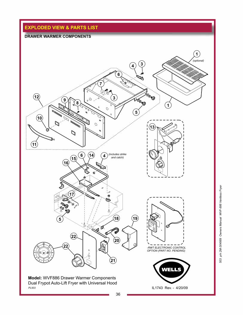
EXPLODED VIEW & PARTS LIST
36
503
p/n
2M
-304
989
Ow
ners
Man
ual
WV
F-88
6 Ve
ntle
ss F
ryer
DRAWER WARMER COMPONENTS
Model: WVF886 Drawer Warmer ComponentsDual Frypot Auto-Lift Fryer with Universal HoodPL503 IL1743 Rev. - 4/20/09
CLOSED OPEN
(optional)
OFF0
LO
HI
WELLS23
45
6
78
-RWT ELECTRONIC CONTROLOPTION (PART NO. PENDING)
(includes strike and catch)
1
13
3
7
89
12
10
4
4
17
14
19
20
21
22
18
615
16
5
5
3
11
6
1
22
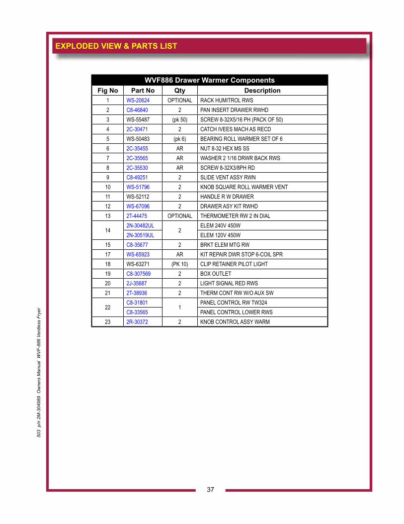
503
p/n
2M
-304
989
Ow
ners
Man
ual
WV
F-88
6 Ve
ntle
ss F
ryer
EXPLODED VIEW & PARTS LIST
37
WVF886 Drawer Warmer ComponentsFig No Part No Qty Description
1 WS-20624 OPTIONAL RACK HUMITROL RWS2 C8-46840 2 PAN INSERT DRAWER RWHD3 WS-55487 (pk 50) SCREW 8-32X5/16 PH (PACK OF 50)4 2C-30471 2 CATCH IVEES MACH AS RECD5 WS-50483 (pk 6) BEARING ROLL WARMER SET OF 66 2C-35455 AR NUT 8-32 HEX MS SS7 2C-35565 AR WASHER 2 1/16 DRWR BACK RWS8 2C-35530 AR SCREW 8-32X3/8PH RD9 C8-49251 2 SLIDE VENT ASSY RWN
10 WS-51796 2 KNOB SQUARE ROLL WARMER VENT11 WS-52112 2 HANDLE R W DRAWER12 WS-67096 2 DRAWER ASY KIT RWHD13 2T-44475 OPTIONAL THERMOMETER RW 2 IN DIAL
142N-30482UL
2ELEM 240V 450W
2N-30519UL ELEM 120V 450W15 C8-35677 2 BRKT ELEM MTG RW17 WS-65923 AR KIT REPAIR DWR STOP 6-COIL SPR18 WS-63271 (PK 10) CLIP RETAINER PILOT LIGHT19 C8-307569 2 BOX OUTLET20 2J-35687 2 LIGHT SIGNAL RED RWS21 2T-38936 2 THERM CONT RW W/O AUX SW
22C8-31801
1PANEL CONTROL RW TW324
C8-33565 PANEL CONTROL LOWER RWS23 2R-30372 2 KNOB CONTROL ASSY WARM
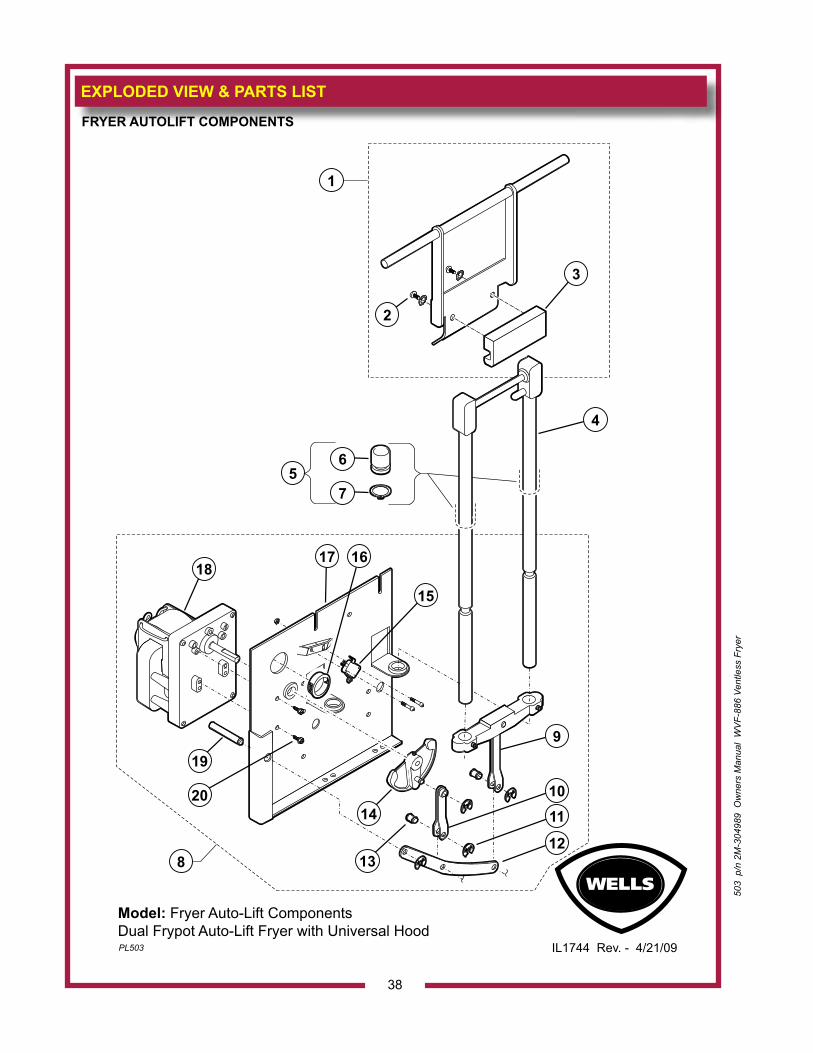
EXPLODED VIEW & PARTS LIST
38
FRYER AUTOLIFT COMPONENTS
Model: Fryer Auto-Lift ComponentsDual Frypot Auto-Lift Fryer with Universal HoodPL503 IL1744 Rev. - 4/21/09
15
161718
9
1110
1213
14
19
20
4
6
75
8
3
2
1
503
p/n
2M
-304
989
Ow
ners
Man
ual
WV
F-88
6 Ve
ntle
ss F
ryer
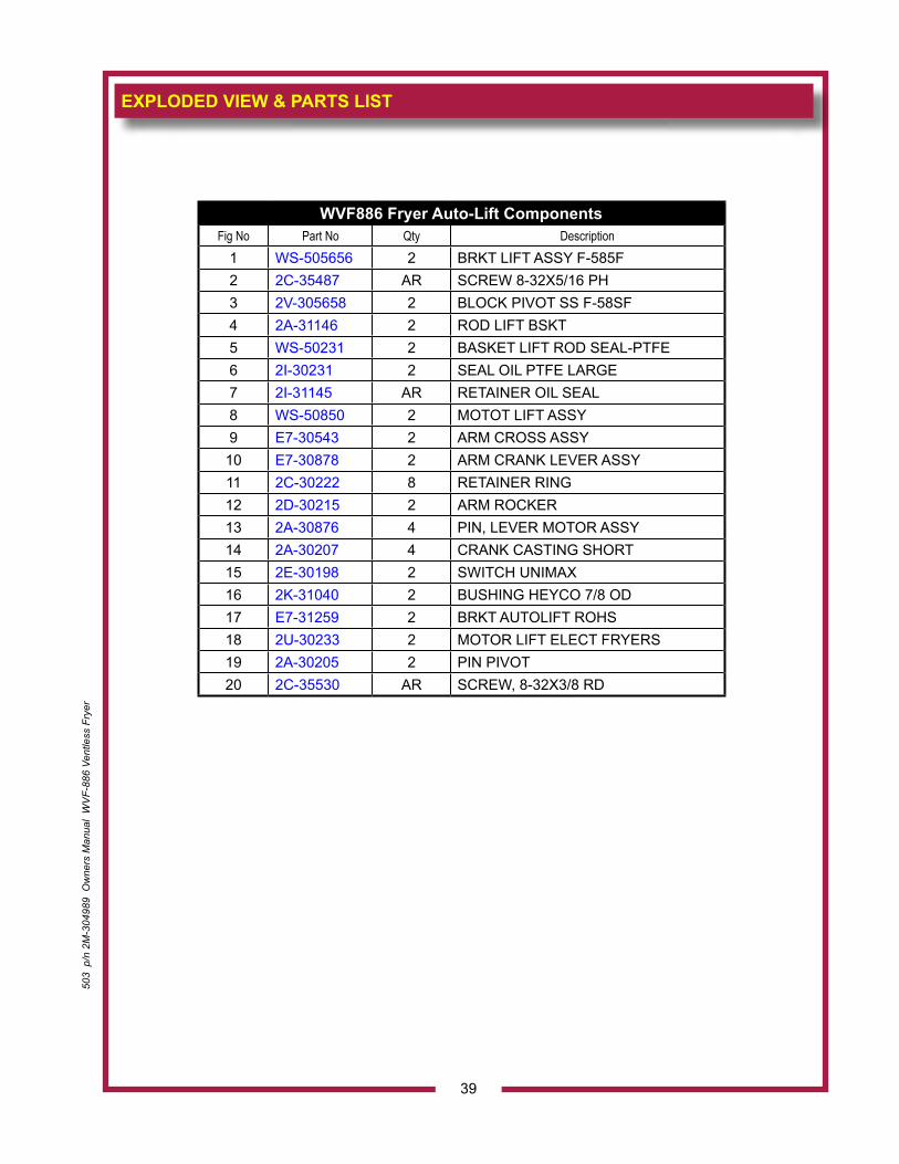
503
p/n
2M
-304
989
Ow
ners
Man
ual
WV
F-88
6 Ve
ntle
ss F
ryer
EXPLODED VIEW & PARTS LIST
39
WVF886 Fryer Auto-Lift ComponentsFig No Part No Qty Description
1 WS-505656 2 BRKT LIFT ASSY F-585F2 2C-35487 AR SCREW 8-32X5/16 PH3 2V-305658 2 BLOCK PIVOT SS F-58SF4 2A-31146 2 ROD LIFT BSKT5 WS-50231 2 BASKET LIFT ROD SEAL-PTFE6 2I-30231 2 SEAL OIL PTFE LARGE7 2I-31145 AR RETAINER OIL SEAL8 WS-50850 2 MOTOT LIFT ASSY9 E7-30543 2 ARM CROSS ASSY10 E7-30878 2 ARM CRANK LEVER ASSY11 2C-30222 8 RETAINER RING12 2D-30215 2 ARM ROCKER13 2A-30876 4 PIN, LEVER MOTOR ASSY14 2A-30207 4 CRANK CASTING SHORT15 2E-30198 2 SWITCH UNIMAX16 2K-31040 2 BUSHING HEYCO 7/8 OD17 E7-31259 2 BRKT AUTOLIFT ROHS18 2U-30233 2 MOTOR LIFT ELECT FRYERS19 2A-30205 2 PIN PIVOT20 2C-35530 AR SCREW, 8-32X3/8 RD
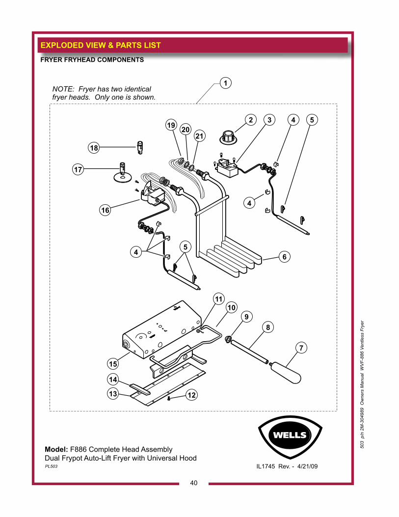
EXPLODED VIEW & PARTS LIST
40
503
p/n
2M
-304
989
Ow
ners
Man
ual
WV
F-88
6 Ve
ntle
ss F
ryer
FRYER FRYHEAD COMPONENTS
Model: F886 Complete Head AssemblyDual Frypot Auto-Lift Fryer with Universal HoodPL503 IL1745 Rev. - 4/21/09
RESET
NOTE: Fryer has two identicalfryer heads. Only one is shown.
2
1
4
6
16
17
18
19 2021
1213
14
15
7
8
1011
9
45
3 4 5
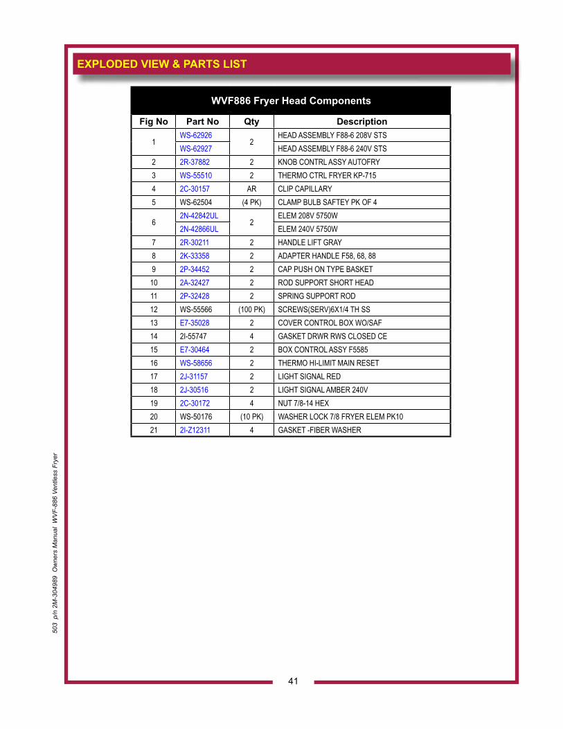
503
p/n
2M
-304
989
Ow
ners
Man
ual
WV
F-88
6 Ve
ntle
ss F
ryer
EXPLODED VIEW & PARTS LIST
41
WVF886 Fryer Head Components
Fig No Part No Qty Description
1WS-62926
2HEAD ASSEMBLY F88-6 208V STS
WS-62927 HEAD ASSEMBLY F88-6 240V STS2 2R-37882 2 KNOB CONTRL ASSY AUTOFRY3 WS-55510 2 THERMO CTRL FRYER KP-7154 2C-30157 AR CLIP CAPILLARY5 WS-62504 (4 PK) CLAMP BULB SAFTEY PK OF 4
62N-42842UL
2ELEM 208V 5750W
2N-42866UL ELEM 240V 5750W7 2R-30211 2 HANDLE LIFT GRAY8 2K-33358 2 ADAPTER HANDLE F58, 68, 889 2P-34452 2 CAP PUSH ON TYPE BASKET10 2A-32427 2 ROD SUPPORT SHORT HEAD11 2P-32428 2 SPRING SUPPORT ROD12 WS-55566 (100 PK) SCREWS(SERV)6X1/4 TH SS13 E7-35028 2 COVER CONTROL BOX WO/SAF14 2I-55747 4 GASKET DRWR RWS CLOSED CE15 E7-30464 2 BOX CONTROL ASSY F558516 WS-58656 2 THERMO HI-LIMIT MAIN RESET17 2J-31157 2 LIGHT SIGNAL RED18 2J-30516 2 LIGHT SIGNAL AMBER 240V19 2C-30172 4 NUT 7/8-14 HEX20 WS-50176 (10 PK) WASHER LOCK 7/8 FRYER ELEM PK1021 2I-Z12311 4 GASKET -FIBER WASHER
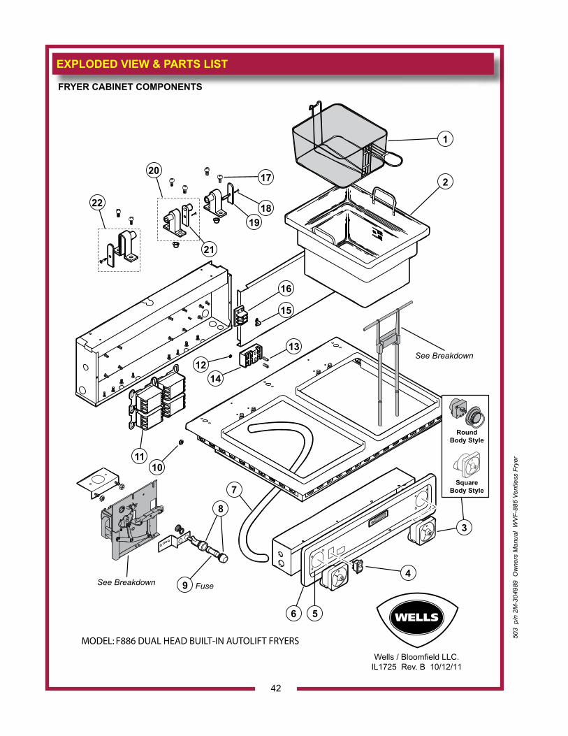
EXPLODED VIEW & PARTS LIST
42
FRYER CABINET COMPONENTS
MODEL: F886 DUAL HEAD BUILT-IN AUTOLIFT FRYERS
Wells / Bloomfield LLC.IL1725 Rev. B 10/12/11
WE LLS
1
2
3
SquareBody Style
RoundBody Style
4
56
9 FuseSee Breakdown
8
7
1011
1214
13
15
16
19
20
22
21
18
17
See Breakdown
503
p/n
2M
-304
989
Ow
ners
Man
ual
WV
F-88
6 Ve
ntle
ss F
ryer
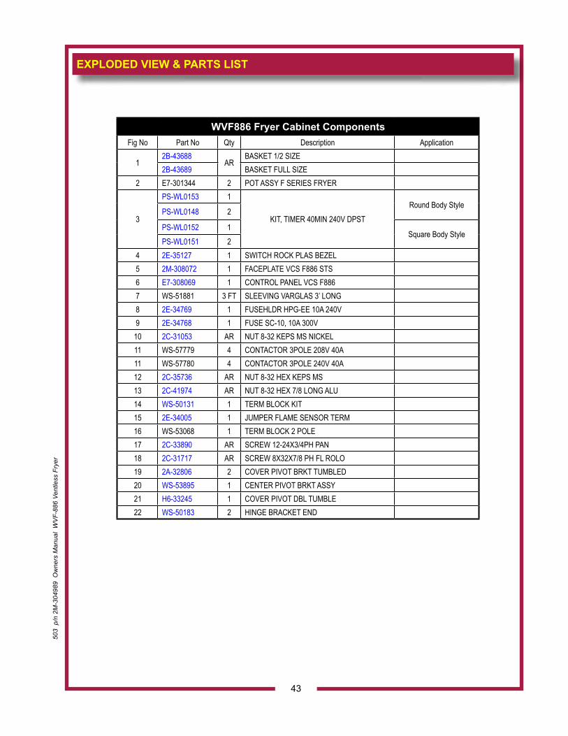
EXPLODED VIEW & PARTS LIST
43
503
p/n
2M
-304
989
Ow
ners
Man
ual
WV
F-88
6 Ve
ntle
ss F
ryer
WVF886 Fryer Cabinet ComponentsFig No Part No Qty Description Application
12B-43688
ARBASKET 1/2 SIZE
2B-43689 BASKET FULL SIZE2 E7-301344 2 POT ASSY F SERIES FRYER
3
PS-WL0153 1
KIT, TIMER 40MIN 240V DPSTRound Body Style
PS-WL0148 2
PS-WL0152 1Square Body Style
PS-WL0151 24 2E-35127 1 SWITCH ROCK PLAS BEZEL 5 2M-308072 1 FACEPLATE VCS F886 STS6 E7-308069 1 CONTROL PANEL VCS F8867 WS-51881 3 FT SLEEVING VARGLAS 3’ LONG8 2E-34769 1 FUSEHLDR HPG-EE 10A 240V9 2E-34768 1 FUSE SC-10, 10A 300V
10 2C-31053 AR NUT 8-32 KEPS MS NICKEL11 WS-57779 4 CONTACTOR 3POLE 208V 40A11 WS-57780 4 CONTACTOR 3POLE 240V 40A12 2C-35736 AR NUT 8-32 HEX KEPS MS13 2C-41974 AR NUT 8-32 HEX 7/8 LONG ALU14 WS-50131 1 TERM BLOCK KIT15 2E-34005 1 JUMPER FLAME SENSOR TERM16 WS-53068 1 TERM BLOCK 2 POLE17 2C-33890 AR SCREW 12-24X3/4PH PAN18 2C-31717 AR SCREW 8X32X7/8 PH FL ROLO19 2A-32806 2 COVER PIVOT BRKT TUMBLED20 WS-53895 1 CENTER PIVOT BRKT ASSY21 H6-33245 1 COVER PIVOT DBL TUMBLE 22 WS-50183 2 HINGE BRACKET END
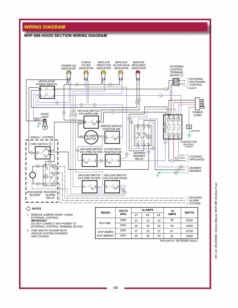
WIRING DIAGRAM
44
503
p/n
2M
-304
989
Ow
ners
Man
ual
WV
F-88
6 Ve
ntle
ss F
ryer
WVF-886 HOOD SECTION WIRING DIAGRAM
VACUUM SWITCHVS4 (AIRFLOW)
VACUUM SWITCHVS1 (PRE-FILTER)
VACUUM SWITCHVS2 (FILTER PACK)
VACUUM SWITCHVS3 (PRE-FILTER)
C
C
C
CONTACTOR208/240VAC
75 AMPS
GROUND
EXTERNALCONTROLTERMINALBLOCK
L1
T1
L2
T2
L3
T3
VENTILATORPOWER SWITCH
31
2
POWERCORD
COOKINGAPPLIANCE
BUILDINGALARMSYSTEM
EXTERNALSHUTDOWNCONTROL
DRAWERWARMER
NC
NO
C
FIRE SWITCH
23
24
15
16 13
6
7
10
NO
NO
NONO
NO NO
POWER ONINDICATOR
CHECKFILTER
INDICATOR
REPLACEPREFILTERINDICATOR
REPLACEFILTER PACKINDICATOR
SERVICEREQUIREDINDICATOR
HOODLIGHTBLACK
BLACKRED
WHITE
GREASE BAFFLEPOSITION SW
FILTER PACKPOSITION SW
1
2
19
18
17
5
9
DRAWERWARMER
RELAY
1
1
2
2
3
3
4
4
5
5
6
DISCHARGEBUZZER
BUILDINGALARMRELAY
ANSUL SYSTEM®
1. REMOVE JUMPER WHEN USING EXTERNAL CONTROL. DO NOT CONNECT ANY POWER TO EXTERNAL CONTROL TERMINAL BLOCK!
IMPORTANT:
2. FIRE SWITCH SHOWN WITH ANSUL® SYSTEM CHARGED AND COCKED
NOTES
JUMPER
BLOWERMOTOR
14
124
2122
25
34
37
3132
33
35
36
12
3
27
118
26
from part no. 2M-302802 issue J
MODEL
VOLTS 60Hz
3ø AMPS 1ø AMPS WATTS
L1 L2 L3
208V
240V
208V
240V
WVF-886 12000 33 32 33 58
12000 29 28 29 50
WVF-886RWWVF-886RWT
12720 37 32 37 61
12900 29 28 29 54
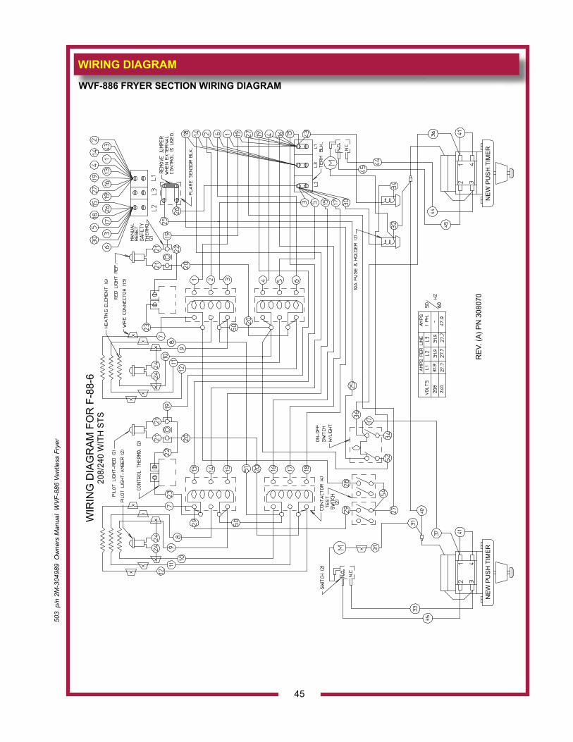
503
p/n
2M
-304
989
Ow
ners
Man
ual
WV
F-88
6 Ve
ntle
ss F
ryer
WIRING DIAGRAM
45
WVF-886 FRYER SECTION WIRING DIAGRAMW
IRIN
G D
IAG
RA
M F
OR
F-8
8-6
208/
240
WIT
H S
TS
RE
V. (A
) PN
308
070
NE
W P
US
H T
IME
RN
EW
PU
SH
TIM
ER
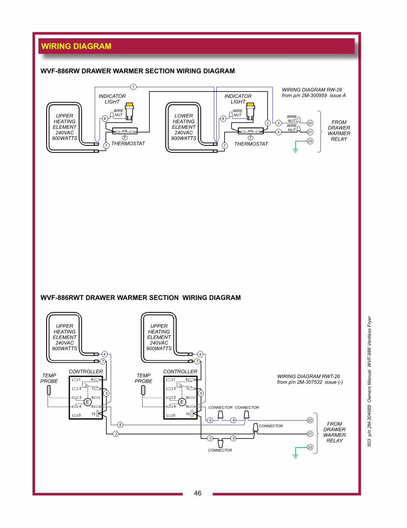
WIRING DIAGRAM
46
503
p/n
2M
-304
989
Ow
ners
Man
ual
WV
F-88
6 Ve
ntle
ss F
ryer
WVF-886RW DRAWER WARMER SECTION WIRING DIAGRAM
UPPERHEATINGELEMENT240VAC
900WATTS T T
FROMDRAWERWARMER
RELAY
INDICATORLIGHT
INDICATORLIGHT
WIRENUT
WIRENUT WIRE
NUTWIRENUT
THERMOSTAT THERMOSTAT
LOWERHEATINGELEMENT240VAC
900WATTS
3232
77
88
1
314
33
WIRING DIAGRAM RW-26from p/n 2M-300959 issue A
UPPERHEATINGELEMENT240VAC
900WATTS
UPPERHEATINGELEMENT240VAC
900WATTS
FROMDRAWERWARMER
RELAY
32
31
33
WIRING DIAGRAM RWT-26from p/n 2M-307532 issue (-)1 1
2 2
3 3
4 4
5 5
6 6
7 7
8 8
9 9
10 10
E E
CONTROLLER CONTROLLERTEMP
PROBETEMP
PROBE
CONNECTOR CONNECTOR
CONNECTOR
CONNECTOR
9
8
6
33
55
77
6
44
WVF-886RWT DRAWER WARMER SECTION WIRING DIAGRAM
503
p/n
2M
-304
989
Ow
ners
Man
ual
WV
F-88
6 Ve
ntle
ss F
ryer
NOTES
47

NOTES
48
503
p/n
2M
-304
989
Ow
ners
Man
ual
WV
F-88
6 Ve
ntle
ss F
ryer
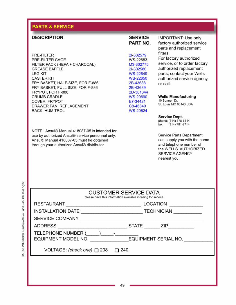
DESCRIPTION SERVICE PART NO.
PRE-FILTER 2I-302579 PRE-FILTER CAGE WS-22683 FILTER PACK (HEPA + CHARCOAL) M3-302775 GREASE BAFFLE 2I-302580LEG KIT WS-22649CASTER KIT WS-22650FRY BASKET, HALF-SIZE, FOR F-886 2B-43688FRY BASKET, FULL SIZE, FOR F-886 2B-43689FRYPOT, FOR F-886 2D-301344CRUMB CRADLE WS-20690COVER, FRYPOT E7-34421 DRAWER PAN, REPLACEMENT C8-46840RACK, HUMITROL WS-20624
NOTE: Ansul® Manual 418087-05 is intended for use by authorized Ansul® service personnel only. Ansul® Manual 418087-05 must be obtained through your authorized Ansul® distributor.
PARTS & SERVICE
CUSTOMER SERVICE DATAplease have this information available if calling for service
RESTAURANT _____________________________ LOCATION _____________INSTALLATION DATE ________________________ TECHNICIAN ___________SERVICE COMPANY ________________________________________________ADDRESS ___________________________ STATE ______ ZIP__________TELEPHONE NUMBER (_____)_____-_________ EQUIPMENT MODEL NO. _______________EQUIPMENT SERIAL NO. ___________
VOLTAGE: (check one) 208 240
49
IMPORTANT: Use only factory authorized service parts and replacement filters.For factory authorizedservice, or to order factory authorized replacement parts, contact your Wells authorized service agency, or call: Wells Manufacturing10 Sunnen Dr.St. Louis MO 63143 USA
Service Dept.phone: (314) 678-6314fax: (314) 781-2714
Service Parts Department can supply you with the name and telephone number of the WELLS AUTHORIZED SERVICE AGENCY nearest you.
503
p/n
2M
-304
989
Ow
ners
Man
ual
WV
F-88
6 Ve
ntle
ss F
ryer
WELLS MANUFACTURING10 Sunnen Dr., St. Louis, MO 63143
telephone: 314-678-6314fax: 314-781-2714
www.wellsbloomfield.com